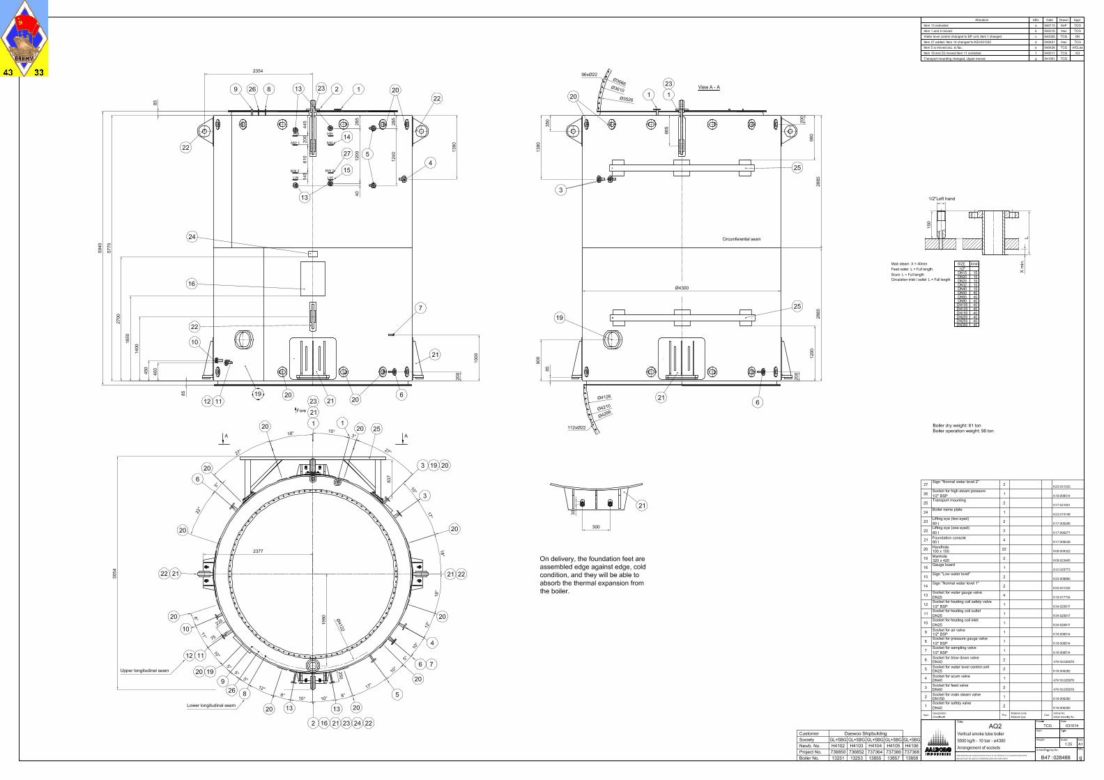
Boiler types: 1 x AQ-2 5500 kg/h Project Nos.: 736850, 736852, 737364, 737366, 737368 Hull Nos.: H 4102, H4103, H4104, H4105, H4106 Customer: Daewoo Shipbuilding & Marine Engineering Co., Ltd. AQ-2 boiler / system concept Chapter No.: Chapter name: 1 Technical data 2 Flow diagrams AQ-2 boiler / accessories 3 Descriptions 4 Operation and maintenance 5 Feed and boiler water 6 Water level gauge 7 Safety valves 8 Feed water system 9 Regulating feed water valve 10 Chemical dosing unit 11 Drawings 12 Data sheets Control system / electrical equipment 13 Alarm annunciator, type M1000 14 Electric drawings for control panel 15 Set point diagrams 16 Data sheets Spare parts 17 Spare parts
Instruction manual for boiler plant file:///D:/00_MY%20PDF/10_ORIG%20BAZA%20PDF%20s%20O...
Стр. 1 из 1 21.10.2010 14:00
CHEMICAL DOSING PUMP OM5540#06.0
Language UK Page 12/12
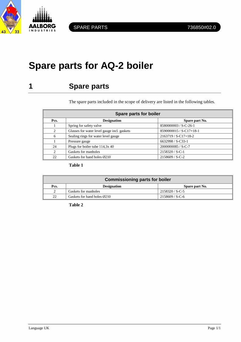
8 Trouble shooting
The trouble shooting list is based on a proper set-up of the chemical dosing pump during commissioning and/or service. The list can be seen in Table 1. Please note that the trouble shooting list is general for chemical dosing pumps and has not been made for any particular plant, but is based on several years of experience. Therefore, the cause of the specific problem may not be mentioned and vice versa. You are always welcome, however, to contact our service department for advice or service assistance.
Fault finding chart
Fault Possible cause Remedy Pump does not prime despite full stroke and bleed function.
Crystalline deposits on the ball seat because valves have dried out.
Remove suction sleeve from chemical supply and rinse out liquid end throughly. If still unsuccessful, dismantle valves and clean.
Fluid is leaking from the back plate.
The liquid end is not sealed against the pump diaphragm.
Tighten screws in the liquid end. If unsuccessful, replace the diaphragm.
Green LED indicator (operating display) is not lit.
Incorrect or no mains voltage. Fuse defective.
Use the recommended mains voltage as given in the voltage specification on the name plate. Contact Aalborg Industries.
Yellow LED display is lit. Liquid level in the chemical storage tank has reached "liquid level low, stage 1", (if provided).
Fill the chemical storage tank.
Red LED display is flashing. Pump operating mode is undefined. Select the required operating mode. Red LED display is lit. Fluid level in the chemical storage tank has reached
"liquid level low, stage 2", (if provided). Fill the chemical storage tank.
Table 1
9 Decommissioning
When dismantling a pump, clean thoroughly, paying particular attention to the liquid end in order to remove all traces of chemicals and dirt. When disposing of a pump it must be broken down into separate material types. All parts must be sent for recycling or for correct disposal according to currently legal waste disposal requirements.
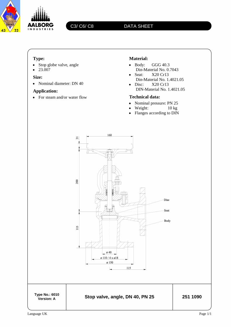
sandwiched between welding neck flanges or slip-on flanges, with horizontal flow or vertical flow upwards. The disc is eccentrically placed in relation to the body to obtain a self-centring effect at installation
Size: • Nominal diameter: DN 150
Connection requirements: • Min. inline diameter of connection
pipe/flange: 159.3 mm • Length of required min. inline diameter:
Technical data: • Operating pressure max: 25 bar • Max. cold hydraulic test pressure: 37.5
bar
• Opening pressure at horizontal flow (60°
open): 13 mbar • Opening pressure at vertical flow
upwards: 16 mbar • Standard Kv value: 840 m3
• Operating temperature max.: 250°C /h
• Operating temperature min.: -10°C • Weight: 4.6 kg
Installation: • The check valve can be installed
sandwiched between welding neck flanges or slip-on flanges
• Determine the correct installation situation and the direction of flow. It must be installed either in a horizontal flow or where the flow is vertically upwards
• The valve is self-centring. However, it must always be ensured that it is completely centred in relation to the connection pipe/flange. Use the body rim (external) diameter for this purpose
• The check valve can be installed directly on a valve, but a distance of 2-3 times the pipe diameter is preferable.
• In case of a steam system with vertical installed check valve a steam trap should be installed for drainage of condensate
• Plug type: Parabolic shaft guided • Flanges according to DIN
Technical data, actuator: • Spring range: 0.4 – 1.2 bar • Diaphragm area: 250 cm² • Filling volume: 2.3 l • Max air pressure: 6 bar • Action: Normally closed valve on air
failure
Technical data, I/P positioner: • Air connection: G ¼” • Inlet air supply: 1.4 to 7 bar, instrument
air • Air inlet consumption in stable state:
< 3.6 x 10-
• Cable inlet: M20 x 1.5 ² Nm³/h
• Input signal: 4-20 mA
• Ambient temperature: -30°C to +80°C • Protection: IP 65
Technical data unit: • Design closing pressure: 16.7 bar • Weight: 19 kg
Technical data: • Nominal pressure: PN 160 • Inlet: G ½" male DIN
19207, form R • Outlet: For steel tube ø 12 • Weight: 0.8 kg
C18 DATA SHEET
Language UK Page 1/1
Water level gauge with illuminator, right
Model 39, DN 25, PN 40
7010 000265 Type No.: 7010
Version: A
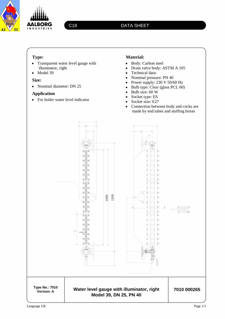
Type: • Transparent water level gauge with
illuminator, right • Model 39
Size: • Nominal diameter: DN 25
Application • For boiler water level indicator
Material: • Body: Carbon steel • Drain valve body: ASTM A 105 • Technical data: • Nominal pressure: PN 40 • Power supply: 230 V 50/60 Hz • Bulb type: Clear (glass PCL 60) • Bulb size: 60 W • Socket type: ES • Socket size: E27 • Connection between body and cocks are
made by end tubes and stuffing boxes
A A
262
85
80 115195
123
60
0
Vis
ible
len
gh
t 1
02
8
34
0
11
3
16
0
85
A - A
10
65
12
00
Electricalconnection 3/4”
C17 DATA SHEET
Language UK Page 1/1
Water level gauge with illuminator, left
Model 39, DN 25, PN 40
7010 000266 Type No.: 7010
Version: A
Type: • Transparent water level gauge with
illuminator, left • Model 39
Size: • Nominal diameter: DN 25
Application • For boiler water level indicator
Material: • Body: Carbon steel • Drain valve body: ASTM A 105 • Technical data: • Nominal pressure: PN 40 • Power supply: 230 V 50/60 Hz • Bulb type: Clear (glass PCL 60) • Bulb size: 60 W • Socket type: ES • Socket size: E27 • Connection between body and cocks are
made by end tubes and stuffing boxes
A A
262
Drain connectionш 19 x 2.5 mild steel
Electricalconnection 3/4”
123
600
113
85
A - A
85
80115
195
Vis
ible
len
ght
10
28
340
16
0
10
65
120
0
2H2/ 2W32 DATA SHEET
Language UK Page 1/2
LED indicator / limit switch 8000 000034 Type No.: 8000
Version: A
Type • LED indicator / limit switch • 5514 A2
Application: • The 5514 with 2 relay outputs is
designed for digital readout of current / voltage or temperature signals.
Relay outputs: • Are selected as either a make or a break
function. The relays can be used as a trip amplifier.
• Two yellow front LEDs indicate the relay status. The relays can be set up with either delayed on or off. Active relay can be selected for either an increasing or decreasing signal. The arrow keys can be used for fast change of the set point.
Technical data: • Panel cut out: 44.5 x 91.5 mm • Weight: 330 g
Electrical specifications:
Common specifications: • Supply voltage:
Max. voltage: 24 VDC
• Auxiliary voltages: 2-wire supply: ≥ 20 V
± 20% Internal consumption: < 3.5 W Max. consumption: 4 W
1 mbar to 20 mbar1 mbar to 30 bar2.5 mbar to 30 bar
• Lower measuring limit
- Measuring cell with silicone oil filling -100 % of max. span or 30 mbar (absolute)
- Measuring cell with inert filling liquid
For process temperature -20 °C < ϑ ≤ 60 °C 30 mbar (absolute)
For process temperature+60 °C < ϑ ≤ 100 °C (max. +85 °C for 30-bar measuring cell)
30 mbar (abs.) + 20 mbar (abs.) · (ϑ - 60 °C)/°C
• Upper measuring limit 100 % of max. span (max. 160 bar with oxygen measurement and inert filling liquid)
• Start-of-scale (continuously adjust.)
• Lower limit (continuously adjustable) 3.55 mA, factory-set to 3.84 mA• Upper limit (continuously adjustable) 23.0 mA, factory-set to 20.5 mA or optional 22.0 mA• Ripple (without HART communication) Ipp ≤ 0.5 % of max. output current• Electric damping- Adjustable time constant (T63) 0 to 100 s in steps of 0.1 s, factory-set to 0.1 s
• Current transmitter Adjustable from 3.55 to 23 mA
• Signal on alarm Adjustable from 3.55 to 23 mALoad• Without HART communication R B ≤ (UH - 10.5 V) / 0.023 A in Ω, UH: power supply in VCharacteristic Linear rising or falling or square-rooted
AccuracyReference conditions Increasing characteristic, start-of-scale value 0 bar, stainless steel seal diaphragm (with level:
mounting flange without tube), silicone oil filling and room temperature (25 °C)r = max. span/set span = span ratio
Error in measurement with fixed-pointsetting (including hysteresis and repeatability)
- Linear characteristicr ≤ 10 ≤ 0.1 %10 < r ≤ 30 ≤ 0.2 %30 < r ≤ 100 ≤ (0.005 · r + 0.05 %)
- Square-root characteristic
Flow > 50 % ≤ 0.1 % at r ≤ 10≤ 0.2 % at 10 < r ≤ 30
Flow 25 to 50 % ≤ 0.2 % at r ≤ 10≤ 0.4 % at 10 < r ≤ 30
• Repeatability Included in error in measurement• Hysteresis Included in error in measurement
Technical data for differential pressure transmitter, type 7MF4433
Piezo-resistive
InputMeasured variable Differential pressure and flow
Between the measuring limits
OutputOutput signal 4 to 20 mA
Response time (T63, without electric damping)
Approx. 0.2 s, approx. 0.3 s with 20- and 60 mbar measuring cells
Ambient temperature effect• At -10 to +60 °C ≤ (0.1 · r + 0.2) %1)
• At -40 to -10 °C and +60 to +85 °C ≤ (0.1 · r + 0.15) % / 10 K1)
Aalborg Industries Data sheet No. 8020 000001 1/3
- 20-mbar measuring cell ≤ 0.2 % per 32 bar
Installation conditions• Installation instructions Any mounting position
Ambient conditions• Ambient temperature(observe temperature class inpotentially explosive atmospheres)- Measuring cell with silicone oil filling -40 to +85 °C30-bar measuring cell -20 to +85 °C- Measuring cell with inert filling liquid -20 to +85 °C- Digital display -30 to +85 °C
• Ambient temperature limits See ambient temperature• Storage temperature -50 to +85 °C
• Climate class- Condensation Permissible
• Degree of protection (to EN 60 529) IP 65• Electromagnetic compatibility- Emitted interference To EN 50 081-1- Noise immunity To EN 50 082-2 and NAMUR NE 21
Technical data for differential pressure transmitter, type 7MF4433Influence of static pressure
• On start-of-scale ≤ (0.15 · r) % per 100 bar
- 20-mbar measuring cell ≤ (0.15 · r) % per 100 bar
Influence of mounting position ≤ 0.7 mbar per 10° inclination
• On span ≤ 0.2 % per 100 bar
Influence of power supply 0.005 % per 1 V change in voltage
Rated operating conditions
Medium conditions• Process temperature- Measuring cell with silicone oil filling -40 to +100 °C30-bar measuring cell -40 to +85 °C (-20 to +85 °C for 7MF4533)- Measuring cell with inert filling liquid -20 to +100 °C30-bar measuring cell -20 to +85 °C
• Process temperature limits See process temperature• Process pressure limits Nominal pressure (PN)
DesignWeight (without options) Approx. 4.5 kgDimensions See drawing
Material• Wetted parts materials- Seal diaphragm Stainless steel, mat. No. 1.4404, Hastelloy C276, mat. No. 2.4819,
- O-ring FPM (Viton) or as option: PTFE, FEP, FEPM and NBR• Non-wetted parts materials- Electronics housing Die-cast aluminium, low in copper, GD-ALSi 12, or stainless steel precision casting,
- Process flange screws Steel, galvanized and yellow-passivized, or stainless steel- Mounting bracket (option) Steel, galvanized and yellow-passivized, or stainless steel
Measuring cell filling Silicone oil or inert filling liquid (max. 160 bar with oxygen measurement)
Process connection Female thread ¼ - 18 NPT and flange connection to DIN 19 213 with mounting thread M10 (M12 for PN 420) or 7/16-20 UNF
Electrical connection Screw terminals, cable inlet via screwed gland Pg 13.5 (adapter), M20 x 1.5 or ½ - 14 NPT, or Han 7D/Han 8U plug
Displays and controlsInput keys 3 for local programming directly on transmitterDigital display Built-in, cover with window (option)
Power supply (U H)Terminal voltage on transmitter DC 10.5 to 45 V and DC 10.5 to 30 V in intrinsically-safe modeRipple Upp ≤ 0.2 V (47 to 125 Hz)
Noise Urms ≤ 1.2 mV (0.5 to 10 kHz)
Aalborg Industries Data sheet No. 8020 000001 2/3
Certificates and approvals Exclusively decisive are the data in the official EU prototype test certificateand the respectively valid supplements
CENELEC To DIN EN 50 014: 1997, EN 50 020: 1994 and EN 50 284: 1999• Intrinsic safety II1/2 G EEx ia IIC T4 / T5 / T6- EU prototype test certificate TÜV 99 ATEX 1494- Max. ambient temperature +85 °C temperature class T4
+70 °C temperature class T5+60 °C temperature class T6
- Connection to certified intrinsically-safe circuits with maximum values
U i = 30 V, Ii = 100 mA,P i = 750 mW, Ri = 300 Ω
- Effective internal inductance L i = 0.25 mH
- Effective internal capacitance C i = 6 nF• Explosion-proof II1/2 G EEx d IIC T4 / T6
- Conformity certificate PTB 99 ATEX 1160- Max. ambient temperature +85 °C temperature class T4
+60 °C temperature class T6
Technical data for differential pressure transmitter, type 7MF4433
$
$
! )!$
)
!$
!
&!
.
!1)
! %
!$ &)'
!.%$/(! 0$
1a Process connection of low-pressure side ¼ – 18 NPT1b Process connection of high-pressure side ¼ – 18 NPT2 Mounting thread M10, M12 or 7/16 – 20 UNF3 Blanking plug 4 Electrical connection:
screwed gland Pg 13.5 (adapter), M20 x 1.5 or ½ – 14 NPT or Han 7D/Han 8U plug
5 Terminal side6 Electronics side, digital display7 Protective cover over keys8 Sealing screw with valve9 Vent on side for liquid measurements
10 Vent on side for gas measurement (suffix H02)11 Mounting bracket (option)
Technical data: • Max. outlet pressure: 16 bar • Max. inlet pressure: 8 bar • Capacity at 16 bar: 1.1 l/h • Stroke at 16 bar: 0.10 ml • Capacity at 8 bar: 1.5 l/h • Stroke at 8 bar: 0.14 ml • Max. frequency: 180 stroke/min • Suction lift: 6 m WG • Max. working temperature at
at max. counter pressure: 50°C • Medium power drain: 20 W • Peak power drain: 1.9 A • Fuse (placed behind
the control panel): 0.8 AT • Enclosure rating: IP 65 • Insulation class: F • Motor: 1 phase AC • Control supply: 115/230 V 50/60 Hz • Weight: 8 kg
96
18
Customer connection 1/2”
Dosing valve
ш 3
0
35
165
590
Ø 410
Feed line to boiler
Relief valve, item 6000 000036
ø 6/ø 4 x 5000 mm PE Hose, item 8615 000022
Air escape valveDosing pump, item 5540 000068
Manual stirrer, item 8500 000339
60 l chemical tank, item 8500 000338
Dosing valve, spring loaded, item 6000 000034
Non return valve, item 6000 000035
2M23 DATA SHEET
Language UK Page 2/2
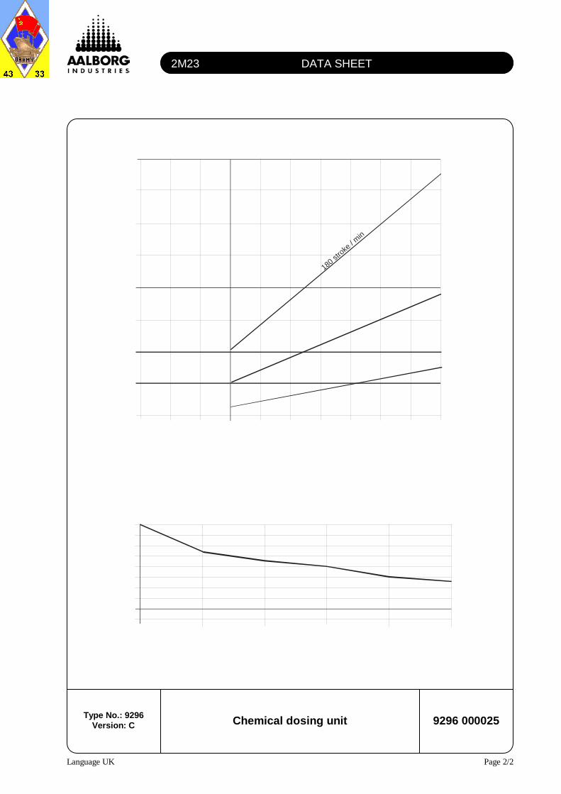
Chemical dosing unit 9296 000025 Type No.: 9296
Version: C
1.5 3 5 8 12 16
0.2
0
0.40.60.81.01.2
1.4
1.61.8
back pressure
0% 10% 20% 30% 40% 50% 60% 70% 80% 90% 100%
0.2
0
0.4
0.6
0.8
1.0
1.2
1.4
1.6
l/h (with medium pressure)
Length of stroke adjustment
180 stro
ke / m
in
90 stroke / min
36 stroke / min
ALARM ANNUNCIATOR, TYPE M1000 OM8220#02.0
Language UK Page 1/6
Alarm annunciator, type M1000
1 General description
The M1000 alarm annunciator provides alarm and light indication for alarms and/or operation indications. It is a compact ten channel programmable unit with a number of features. An input signal originating from a potential free contact, normally open or normally closed, will cause the appropriate alarm LEDs to flash and simultaneously the related output to activate. The internal siren relay will be activated together with the detection of every new alarm. Figure 1 and Figure 2 show the front and rear of the alarm annunciator respectively.
Front view of the alarm annunciator
Figure 1 M1000_a.cdr
ALARM ANNUNCIATOR, TYPE M1000 OM8220#02.0
Language UK Page 2/6
Rear view of the alarm annunciator
Figure 2 M1000_b.cdr
2 Terminals and switches
The position of the terminals, switches, etc. appears from Figure 2. INPUTS - terminal 1-10 Alarm inputs for connection of potential free contacts, normally open or normally closed with positive reference. Negative reference is possible. TEST- terminal 11 Will activate all LEDs to perform a lamp test. Active when connected to + (terminal 28). RESET- terminal 12 Resets the siren relay and the "ALARM-OUT" signal. Flashing light in LEDs will change to steady light if the input signal is still active. Active when connected to + (terminal 28). BLOCK - terminal 13 Will block for incoming alarms. Active when connected to positive supply. ALARM-IN - terminal 14 Provides indication of first incoming alarm on multiple unit installations.
ALARM ANNUNCIATOR, TYPE M1000 OM8220#02.0
Language UK Page 3/6
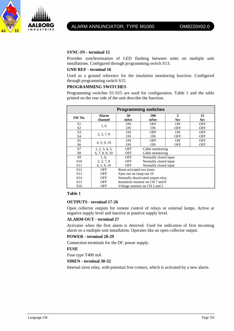
SYNC-IN - terminal 15 Provides synchronisation of LED flashing between units on multiple unit installations. Configured through programming switch S13. GND REF - terminal 16 Used as a ground reference for the insulation monitoring function. Configured through programming switch S15. PROGRAMMING SWITCHES Programming switches S1-S15 are used for configuration. Table 1 and the table printed on the rear side of the unit describe the function.
Reset activated two times Sync-out on lamp-out 10 Normally deactivated output relay Insulation monitor on CH 7 and 8 Voltage monitor on CH 2 and 3
Table 1
OUTPUTS - terminal 17-26 Open collector outputs for remote control of relays or external lamps. Active at negative supply level and inactive at positive supply level. ALARM-OUT - terminal 27 Activates when the first alarm is detected. Used for indication of first incoming alarm on a multiple unit installation. Operates like an open collector output. POWER - terminal 28-29 Connection terminals for the DC power supply. FUSE Fuse type T400 mA SIREN - terminal 30-32 Internal siren relay, with potential free contact, which is activated by a new alarm.
ALARM ANNUNCIATOR, TYPE M1000 OM8220#02.0
Language UK Page 4/6
3 Functions
3.1.1 General function
The function described in this section assumes that the M1000 unit has been configured for default operation - all programming switches are closed. A potential free contact connected to one of the ten input terminals will cause the appropriate alarm channel to activate. The activation of an alarm is indicated by a flashing light in the related LEDs and the activation of the related open collector output. The first incoming alarm is indicated with a quickly flashing light following alarms are indicated with slowly flashing light. The LEDs will keep flashing until the alarms are acknowledged, even though the signals have been disconnected from the input terminals. Pressing the "RESET" push button will acknowledge all new alarms, and all LEDs will change to steady light, provided that the related input signals are still present upon acknowledgement. Pressing the "RESET" button will also cause the siren relay to deactivate. Each open collector output will stay active as long as the related LEDs are lit.
3.1.2 Input and output terminals All input terminals are located on the left side of the unit, and all output terminals are located on the right side (facing the rear plate). The input is considered active when connected to positive supply and inactive when disconnected. Please note that the alarm input can be configured to operate on normally closed contacts. The output is "open collector" output. An open collector output will be at negative supply level when active and at positive supply level when inactive. No current originates from an open collector output, it should only be considered as an electronic contact to minus supply level. External voltage, equal to the unit supply voltage, must always be provided to drive the relay or lamp controlled by an open collector output. Maximum drive capacity of an output is 150 mA.
3.1.3 Input delays
Each input can be configured with an input delay. Programming switches S1 to S6 are used to select a predefined delay for a combination of input. Input delays are convenient where alarms are dependant upon the time of activation. Alarm condition would occur only if the alarm is active for more than e.g., 15 seconds. The delay values are found in the programming table.
3.1.4 Cable monitoring This feature is not in use. Programming switches S7 and S8.
3.1.5 Normally open or normally closed contacts Programming switches S9 to S11 determine the state and operation of the potential free contact connected to an input terminal. A normally open (NO) contact is disconnected when no alarm is present. A normally closed (NC) contact provides a signal when no alarm is present. Normally closed relay contacts are often used as they provide the safety of alarm annunciation in case the supply is lost.
ALARM ANNUNCIATOR, TYPE M1000 OM8220#02.0
Language UK Page 5/6
3.1.6 Reset push button activated two times After reset with programming switch S12 open, the steady light is maintained until the reset push button is again activated, provided that the fault has been cleared.
3.1.7 Sync-out output 10 The sync-out function provides the possibility of synchronised LED flashing between units in a multiple unit installation. The selection of this function through programming switch S13 on one arbitrary unit disables the default output function of terminal 26. Sync-out has no functional importance other than providing visual continuity. The wiring connection for this function is found in the diagram shown in Figure 3.
Wiring for synchronised flashing
Figure 3 M1000_d.cdr
3.1.8 Normally deactivated siren The default operation of the siren relay will cause terminal 30 and 31 to be shorted during alarm or supply failure. Setting programming switch S14 to its open position will invert the function so that the connection between terminal 31 and 32 exists only during alarm condition.
3.1.9 Dimming It is possible to adjust the brightness of the front plate LEDs by pressing the "TEST" push button, or terminal 11 (TEST), to + (terminal 28) more than six seconds. Dimming is done in four consecutive levels. The default brightness is re-obtained by activation of the "TEST" signal. The "TEST" push button connects terminal 11 for two seconds.
3.1.10 Insulation monitoring This feature is not in use. Programming switch S15.
3.1.11 Voltage monitoring This feature is not in use. Programming switch S16.
3.1.12 First incoming alarm on multiple units The M1000 includes a special indication of the first incoming alarm. This function can be extended to cover multiple units, thus it will be possible to indicate the first of e.g., 50 alarms. In order to obtain this function, a single wire must be interconnected between all the M1000 units. The wire must have a connection to (terminal 14) "ALARM-IN" and (terminal 27) "ALARM-OUT" on each unit as shown in Figure 4.
Sync-in Sync-in Sync-in Sync-in
M1000 M1000 M1000 M1000
Sync-out
15 15 15 15
26
ALARM ANNUNCIATOR, TYPE M1000 OM8220#02.0
Language UK Page 6/6
Wiring for first incoming alarm on multiple units
Figure 4 M1000_e.cdr
3.1.13 Test function The "TEST" push button and the "TEST" terminal (terminal 11) provide illumination of all LEDs. An extended test function is available through the simultaneous activation of both the "TEST" and "RESET" push buttons. Press and hold the two push buttons. LEDs will illuminate, after three seconds the siren relay will activate, and after six seconds the output will activate.
4 Wiring example
Figure 5 shows the default connection of the input and output terminals of the M1000 unit. The Input is connected to the positive supply through potential free contacts. Lamps connected to the outputs are supplied from the same supply source as the unit. External switches are provided for "TEST", "BLOCK", and "RESET".
Wiring diagram (default connection)
Figure 5 M1000_f.cdr
Alarm-in Alarm-in Alarm-in Alarm-in
M1000 M1000 M1000 M1000
Alarm-out Alarm-out Alarm-out Alarm-out
14 14 14 14
27 27 27 27
1 IN1
2 IN2
3 IN3
4 IN4
5 IN5
6 IN6
7 IN7
8 IN8
9 IN9
10 IN10
11 TEST
12 RESET
13 BLOCK
OUT10 26
OUT9 25
OUT8 24
OUT7 23
OUT6 22
OUT5 21
OUT4 20
OUT3 19
OUT2 18
OUT1 17
Supply
28
+
-
29
30
31
32
Siren
M1000
List of Indicators and Set Points
Item Units Range Set Point Type Indicator ITEM NO IN DRAWING Element Alarm Bnr Physical Remarks(Proposal) ID-NO 1) List of mountings: X01: 026813 Terminal output Trip Location
in wiring 2) Boiler gauge board: No. in terminal indiagram 3) Burner drawing: 91X02: 029753 wiring wiring
Safety Valve BAR 10,0 25.912High Steam Pressure Switch BAR 1-10 9,6 RT30 82A2C C30 26B11C X1: 15-16 X1: 218-219 X BoilerSteam Pressure Transmitter BAR 0-10 MBS 5100 C30 71A4D X6: 12-13 BoilerStart/Stop Pressure BAR 1-10 6,5/7,5 PR2231 81A2C 71A7B X6: 12-13 Boiler
Load Controller: Sipart 6DR 2105 71A2B 71A2B X6: 12-13 Panel Regarding more detailedSet Point - W BAR 0-10 7,0 information about the loadProportional Band - XP % 2-200 100 controller please see theIntergral Time - IN Min. 0,7-10 0,7 burner instruction manual.Derivative Time - IV Min. 0-5 0Neutral Zone - XSH % 0,5-0,6 0,5
Fuel oil temperature Controller: Sipart 6DR 2105 25A1B 25A1B X6: 8-9 Panel Regarding more detailedSet Point - W °C 0-150 90 information about the loadProportional Band - XP % 2-200 100 controller please see the
Oil Ringline Pressure D.O. BAR 1-5 1,2 45-6 22Y10F X1: 13-14 Oil LineOil Ringline Pressure H.F.O. BAR 1-5 1,9 45-6 22Y10F X1: 13-14 Oil LineLow Oil Pressure Switch BAR 0-3,5 0,5 KPS 33 84A2C 72 62S3C X1: 34-35 X1: 248-249 X BurnerLow Com. Air Pressure Switch mBAR 2,5-50 20 GW 50 A4 82A2C 9 63S1C X1: 38-39 X1: 208-209 X BurnerLow Prim. Air Pressure Switch mBAR 2,5-50 30 GW 50 AV 82A2C 32 63S3C X1: 36-37 X1: 206-207 X BurnerFire in wind box
Water Level Monitoring Regarding more detailedWater Level Transmitter mA 4-20 NRG 26-1 24P6D 24A1D X6: 0-1-2-3 Boiler information about the water(Calibration) mA 4-20 level monitoring systemWater Level Controller: % 100-0 50,5 (NW) Sipart 6DR 2105 24A9B 24A9B X6: 6-7 Panel please see the boiler Set Point - W mA 4-20 11,9 instruction manualProportional Band - XP % 1,5 100Intergral Time - IN Min. 0,7-10 1Derivative Time - IV Min. Fixed 0Set Point For Water Level Switches(Float Type), Are With Ref. ToNormal Water Level - NW = 0
21.10.2010 1D__SETPOINTLIST 736849-52.XLS Page 1
List of Indicators and Set Points
Item Units Range Set Point Type Indicator ITEM NO IN DRAWING Element Alarm Bnr Physical Remarks(Proposal) ID-NO 1) List of mountings: X01: 026813 Terminal output Trip Location
in wiring 2) Boiler gauge board: No. in terminal indiagram 3) Burner drawing: 91X02: 029753 wiring wiring
Too high water level mm WG PR2231 82A2C 24A3B X1: 254-255 XHigh Water Level mm WG PR2231 82A2C 24A3B X1: 222-223 BoilerNormal Water Level mm WG 0Low Water Level mm WG PR2231 82A2C 24A6B X1: 224-225 BoilerToo Low Water Level 1 mm WG NRG 16 82A2C 26A2B X1: 226-229 X BoilerToo Low Water Level 2 mm WG NRG 16 82A2C 25A8B X1: 226-229 X Boiler
High temperature in up takeoC 400 20-500 JUMO 84A2C K5 35B5E X1: 19-20 X1: 256-257 X Up take
Stand by oil pump start BAR 1,5 0-3,5 KPS 33 83A2C 75B11B X1: 20-21 X1: 230-231 Oil line
Power Failure 80H1F X1: 232-233 X PanelBurner Swing Out Limit Sw. 84A2C 1F 32S5C X1: 32-33 X1: 214-215 X PanelFlame Failure Auto RAR7/LOK 18 67B13C X1: 73-74 X1: 200-201 X Bnr. + PanelFlame Failure man 1 RAR7/LAE10 18 64B13C X1: 40-41 Bnr. + Panel Cut Off Oil SupplyFlame Failure man 2 RAR7/LAE10 18 60B6B X1: 42-43 Bnr. + Panel Cut Off Oil Supply
Motor Load Indicators:Burner Motor A 0-10 EQ72-PV 10P6C 10P6CCombustion Air Fan A 0-25 EQ72-PV 10P4C R1 10P4C
Motor space heating:Fuel Oil Service Pump 1 W 26 72R6E X1: 280-281 G5Fuel Oil Service Pump 2 W 26 72R8E X1: 282-283 G12
Thermal Overload Relays:Burner Motor A 5.5-8 6.3 LR2-D1512 83A2C 10M5D X1: 204-205 X PanelCombustion Air Fan A 25-32 28 LR2-D3553 83A2C 1R 10M3D X1: 202-203 X PanelIgnition Oil Pump A 0.63-1.0 0.6 GV2-P05 83A2C G145 10Q7B PanelOil transfer pump 1 A 1-1.6 1.4 GV2-P06 G147 10Q9B PanelOil transfer pump 2 A 1-1.6 1,4 GV2-P06 G147 10Q11B PanelHigh Salinity uS/cm 0-400 10 Gestra LRS1-5b 32A10A X1: 256-257 PanelHigh Oil Content MCU 2000 X1: 91-94 X1: 250-251 F.W. line
21.10.2010 1D__SETPOINTLIST 736849-52.XLS Page 2
List of Indicators and Set Points
Item Units Range Set Point Type Indicator ITEM NO IN DRAWING Element Alarm Bnr Physical Remarks(Proposal) ID-NO 1) List of mountings: X01: 026813 Terminal output Trip Location
in wiring 2) Boiler gauge board: No. in terminal indiagram 3) Burner drawing: 91X02: 029753 wiring wiring
Timers:Delay Too Low Water Level 1 Sec. 3-60 15 NRG 16-1 26A2B PanelDelay Too Low Water Level 2 Sec. 3-60 15 NRG 16-1 25A8B PanelDelay Low Combustion Air Press. Sec. 3-60 10 SIEMENS 66K12F PanelDelay Low Atomizing Air Press. Sec. 3-60 10 SIEMENS 66K13F PanelDelay After Running Time For Rot. Sec. SIEMENS 67K5F PanelDelay St.By Oil Transfer Pump Sec. SIEMENS 76K14F Panel
Burner Servo Motor Limit Switches: See sheet 68 in wiringMax. Position Degr. 0-90 90 DFT-KPII Burner diagram and burner Min. Position Degr. 0-90 0 DFT-KPII Burner instruction manualCompound Reg. Limit Switches: Final Adj. During CommissionMax. Position Degr. 0-90 85 DFT-ZCK BurnerMin. Position Degr. 0-90 3 DFT-ZCK Burner
21.10.2010 1D__SETPOINTLIST 736849-52.XLS Page 3
List of Indicators and Set Points
Item Units Range Set Point Type Indicator ITEM NO IN DRAWING Element Alarm Bnr Physical Remarks(Proposal) ID-NO 1) List of mountings: X01: 026813 Terminal output Trip Location
in wiring 2) Boiler gauge board: No. in terminal indiagram 3) Burner drawing: 91X02: 029753 wiring wiring
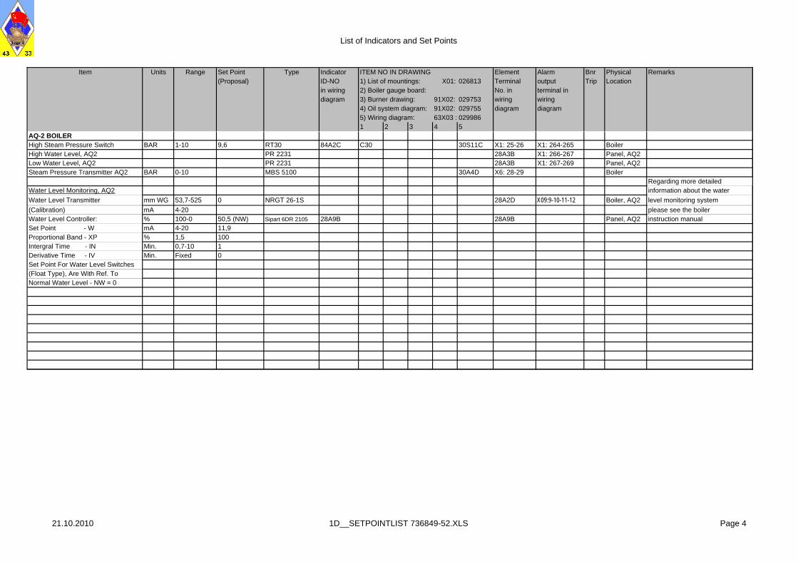
Regarding more detailedWater Level Monitoring, AQ2 information about the water
Water Level Transmitter mm WG 53,7-525 0 NRGT 26-1S 28A2D X09:9-10-11-12 Boiler, AQ2 level monitoring system
(Calibration) mA 4-20 please see the boiler Water Level Controller: % 100-0 50,5 (NW) Sipart 6DR 2105 28A9B 28A9B Panel, AQ2 instruction manualSet Point - W mA 4-20 11,9Proportional Band - XP % 1,5 100Intergral Time - IN Min. 0,7-10 1Derivative Time - IV Min. Fixed 0Set Point For Water Level Switches(Float Type), Are With Ref. ToNormal Water Level - NW = 0
21.10.2010 1D__SETPOINTLIST 736849-52.XLS Page 4
DATA SHEET
Language UK Page 1/2
Alarm panel, M1000-24-10B 8220 000011 Type No.: 8220
Version: A
Type: • Alarm annunciator unit • M1000-24-10B
Application: • 10 channel programmable unit for alarm
/ operation indication.
Technical data: • Voltage supply: 24V DC -70% / +30% • Max power comsumption: 180 mA • Fuse type: T400mA • Output relay: Max. 220V AC/2A 30V
DC 2A 30W • Output: Max. 150 mA per channel • LED flash frequency:


![pc pc 2012 - examenbac.com · NS28 / (aq) (s) (s) (aq) 10 —2 + = ] (aq) i 4(aq) mol. L; 1 + = ' (aq) i (aq) 4(aq) 7m +Cu2+ + 4....*àA.Z = 5.1036 F = 9, 65.104 C.mol- —2](https://static.documents.pub/doc/80x56/5b9bedcb09d3f29b498bc24a/pc-pc-2012-ns28-aq-s-s-aq-10-2-aq-i-4aq-mol-l-1-.jpg)


![Aula #23 · AgCl (s) Ag+ (aq) + Cl-(aq) Ksp = [Ag +][Cl K sp is the solubility product constant MgF 2 (s) Mg2+ (aq) + 2F-(aq) Ksp = [Mg 2+][F]2 Ag 2 CO 3 (s) 2Ag+ (aq) + CO3 2-(aq)](https://static.documents.pub/doc/80x56/5f08237a7e708231d42087a7/aula-23-agcl-s-ag-aq-cl-aq-ksp-ag-cl-k-sp-is-the-solubility-product.jpg)

![Section 7.6: Solubility Equilibria and the Solubility Product ...Write the solubility product constant equation. K sp=[Ag +(aq)][I!(aq)] [Ag+(aq)]=[I!(aq)] K sp=[Ag +(aq)]2 Step 3.](https://static.documents.pub/doc/80x56/6123f8ac1375fc2ea57b63da/section-76-solubility-equilibria-and-the-solubility-product-write-the-solubility.jpg)

