+ All Categories
Home > Documents > AR ABOVE RAIL UNIT COOLER 156 MODELS

AR ABOVE RAIL UNIT COOLER 156 MODELS

Date post: 22-Mar-2022
Category:
Upload: others
View: 6 times
Download: 0 times
Share this document with a friend
12
Bulletin 3500 AR – Above Rail Unit Cooler AR ABOVE RAIL UNIT COOLER 156 MODELS Ammonia, Halocarbon, and Glycol Refrigerants 1 to 12 Tons Refrigeration (3.5 to 42 kW) 3100 to 27,200 CFM (1463 to 12,836 L/s) • Air Defrost • Hot Gas Defrost • Water Defrost • Medium and High Temperature “The Heat Transfer Experts”
Transcript

Bulletin 3500 AR – Above Rail Unit Cooler

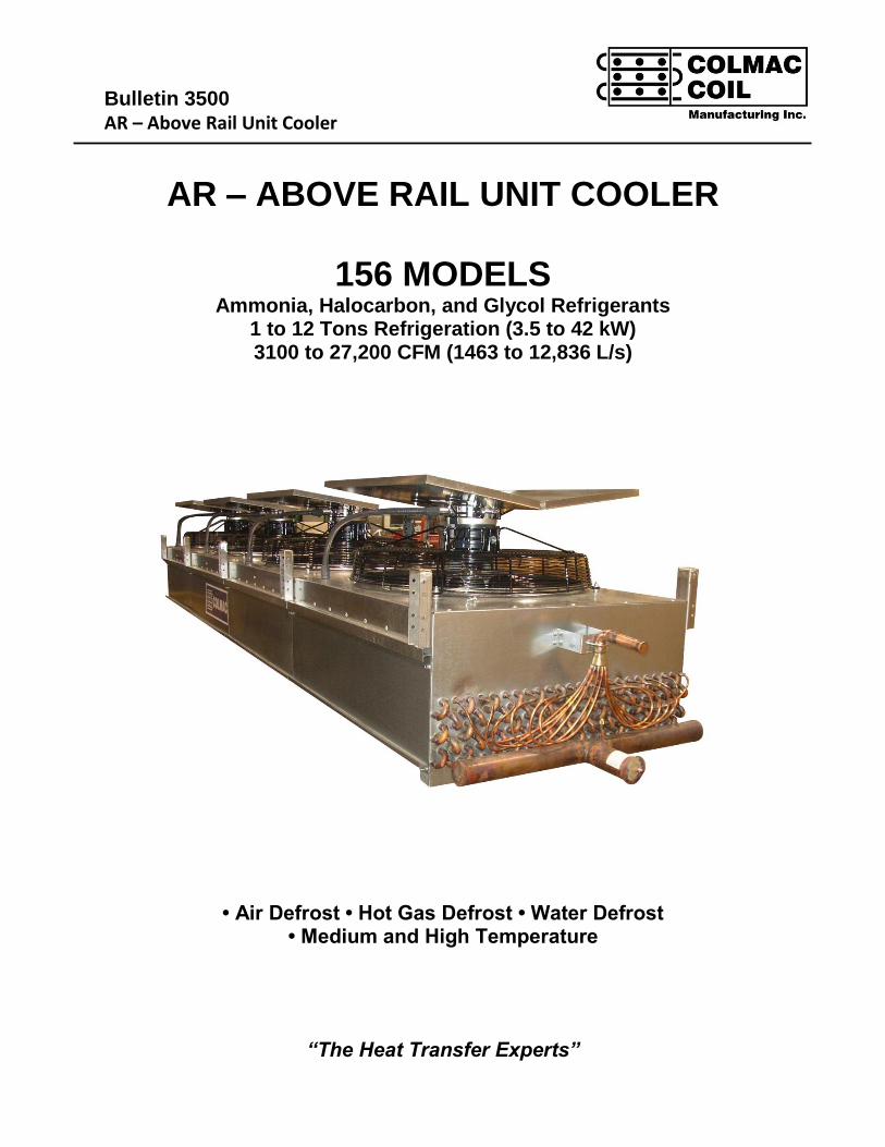
AR – ABOVE RAIL UNIT COOLER

156 MODELS Ammonia, Halocarbon, and Glycol Refrigerants

1 to 12 Tons Refrigeration (3.5 to 42 kW) 3100 to 27,200 CFM (1463 to 12,836 L/s)

• Air Defrost • Hot Gas Defrost • Water Defrost • Medium and High Temperature

“The Heat Transfer Experts”

Page 2

TABLE OF CONTENTS

MODEL NOMENCLATURE ............................................................................................................. ..........................2

ENGINEERING SPECIFICATIONS ...........................................................................................................................3

OPTIONAL FEATURES .............................................................................................................. ...............................4

APPLICATION GUIDELINES ......................................................................................................... ...........................5

RATINGS, ENGLISH ..................................................................................................................................................6

RATINGS, SI .................................................................................................................... ......................................7

REFRIGERANT CONNECTION SIZES .....................................................................................................................8

DEFROST AND DRAINPAN CONNECTIONS ............................................................................................... ...........8

SPECIFICATIONS, ENGLISH & SI UNITS............................................................................................. ...................9

ELECTRICAL SPECIFICATIONS ...................................................................................................... ........................11

UNIT DIMENSIONS ....................................................................................................................................................11

MODEL NOMENCLATURE"AR" Above the Rail Unit Cooler

AR 9 - 4 2 4 X - G - 24 1/2 - FLA - H - B

FACE AREASq. Ft. / Fan 6,9,11

FPI: 4

HOUSING:G - GALVA - ALUMS - SST

FANS: 1 THRU 5

ROWS: 4,6,8

TUBE SIZEL - 5/8"X - 1"

FAN DIA, IN: 20,24,30

FAN HP: 1/3, 1/2, 3/4

VOLTAGE CODE:B - 208-230/60/3D - 460/60/3H - 200/50/3 I - 400/50/3

DEFROST:A - AIRH - HOT GASW - WATER

CIRCUITING:FLA - Flooded AmmoniaRTA - Recirc Top Feed NH3RBA - Recirc Bottom Feed NH3DXA - DX NH3DXH - DX HalocarbonRTH - Recirc Top Feed HalocarbonRBH - Recirc Bottom Feed Halocarbon PG - Propylene Glycol EG - Ethylene Glycol

Page 3

ENGINEERING SPECIFICATIONS

I. EVAPORATORS GENERAL

• Coil - Ammonia - FL and RB: To be constructed with 1" OD x .065" wall seamless drawn Aluminum tubing. Ammonia - RT and DX: To be constructed with 5/8" OD x .049" seamless drawn Aluminum tubing.Halocarbon - FL and RB: To be constructed of 1" x .035" wall seamless, Copper tubing.Halocarbon - RT and DX: To be constructed with 5/8" x .025" seamless, Copper tubing.**Glycol: To be constructed with 5/8" x .025" seamless, Copper tubing.**Consult Factory for Performance Ratings.

• Fins - Shall be aluminum 1100 alloy. Fins shall be continuous flat plate type with full length, self-spacing collars.Tubes to be staggered in direction of airflow, expanded into fin collars to form a tight mechanical bond betweentube and fin.

• Headers - Ammonia: Shall be made of schedule 40 (minimum) Aluminum pipe. All joints TIG welded. Halocarbon: Shall be made of Type "L" Copper. All joints brazed with 5% Silver Solder.

• Coil Connections - Ammonia - Shall be aluminum flange unions. (Dielectric bushing and washers which willelectrically isolate aluminum coil flanges from the supplied mating steel socket weld flanges, are optional.)Halocarbon - Copper "sweat.".

• Ammonia Coils - Shall be tested for leaks after welding at 500 psig (35 bar) with dry air under water.Halocarbon coils - Shall be tested for leaks after welding at 350 psig (25 bar) with dry air under water.

• Fans & Motors - Propeller fans constructed of Aluminum blades on steel spiders. 20" (508mm) and 24" (610mm)diameter fans driven at 1140/950 RPM @ 60/50 Hz. 30" (762mm) diameter fans driven at 850/950 RPM @ 60/50 Hz. Fan motors to be TEAO severe duty. Motors have ball bearings and internal thermal protection, SinglePhase and Three Phase.

• Cabinet - Standard construction is of 16 Ga. Galvanized Steel, with Aluminum drainpans and access panels.(Special materials are also available. See Optional Features)

• Drainpans - Drainpan shall be insulated and protected by a galvanized steel cover. Note: Insulated Drain Pans are required by the USDA in meat processing facilities.

II. CIRCUITING

• Liquid Overfeed Circuiting - RB (Recirc. Bottom Feed) coils are circuited parallel-flow to optimize circuit feedingand coil performance at all load conditions. RT (Recirc. Top Feed) coils must be circuited counter-flow becauseof vertical-up airflow. Liquid overfeed orifices shall be used at each circuit entrance, sized for 5 psi pressure dropto insure good liquid distribution.

• Flooded Circuiting - FL (Gravity Flooded) coils are circuited parallel flow to optimize circuit feeding and coilperformance at all load conditions.

• Direct Expansion Circuiting - DX coils are circuited counterflow to produce superheated refrigerant on last pass.(Required for thermostatic expansion valve operation).

Page 4

III. DEFROST

• Hot Gas Defrost - Coils arranged for hot gas defrosting shall be "coil only" defrost. (Heated drainpan is available asan option - see Optional Features).

• Water Defrost - Coil to be arranged for water defrosting. Water shall be distributed evenly over the entire coil surface(excluding return bends and headers) by a spray tree, mounted above the fins. Piping is external for easy access tonozzles.

IV. APPROVED VENDOR

• Approved Vendor - Colmac Coil Manufacturing, Inc. Model: AR_______________________

V. ORDERING INFORMATION

• Please Specify

1. Complete model number.

2. Saturated suction temperature.

3. Room temperature.

4. Overfeed ratio (if pump recirculatedd).

5. Options or special features.

OPTIONAL FEATURES

(Consult Factory for more information)

• Dual circuiting for capacity control. • Stainless steel or all Aluminum cabinet.

• Corrosion resistant fin coatings. • Dielectric steel flanges & bolts.

• Variable fin spacing for heavy frost • Electric Defrost.

conditions. First row on 4 row coils • Heated Drainpan, Hot Gas Defrost.

and first 2 rows on 6 and 8 row coils • Fan Speed Controls, Single and three

are 2 FPI, remaining rows of coil are 4 FPI. phase

Page 5

APPLICATION GUIDELINES

AR Unit Coolers are suitable for produce storage areas, populated cold-storage work areas, and other applications wherea low profile and low air-velocities are required.

Fan Motor Heat - Is not included in the ratings and should be added to the room cooling load as follows:

Low Coil Face Velocity - 600 FPM, or less - Allows AR units to operate with a wet surface without moisture carry-over.

High TD's are recommended when dirty air has the potential for coating the fins with debris (loading docks, etc.), and whenlow humidity is desired.

• Frosted fins are "cleaned" during defrost cycle.• High TD's ensure better performance with dirty fins in no-frost conditions.• Colder fins condense more moisture.

Low TD's - Approx. 10°F (6°C) - are recommended for high humidity applications such as Carcass Chillers and WetProduce storage.

• Carcass Chilling requires a higher initial refrigeration capacity. Removing body heat raises initial TD duringpulldown. Size liquid lines for the maximum load anticipated.

Units should be located so that the air discharges parallel to beams whenever possible.

Recommended Coil Circuiting for Ammonia

RB - Pump Recirculated, Bottom Feed - Is recommended for all hot gas defrost systems. The coil should always have hotgas fed at the top (suction) to ensure good liquid and oil drainage during defrost.

RT - Pump Recirculated, Top Feed - Is recommended for all air and water defrost systems. Although not recommended,top Feed can also be used in hot gas defrost systems provided hot gas is fed into the liquid header at the top of the coil.Gas flowing through the liquid feed orifices will experience some pressure drop which may penalize defrost performance.

FL - Gravity Flooded, Bottom Feed - Is typically cost effective for small systems (4 evaporators or less), and isrecommended when a variable load exists. May be used with Hot Gas or Water Defrost, provided the coil has hot gas fedinto the suction header to ensure good liquid and oil drainage during defrost.

DX - Direct Expansion Feed - Should not be used when saturated suction temperature is 0°F (-18°C) or less. For bestresults, DX coils should be used with a minimum TD of 12 to 15°F (7 to 9°C)

• Liquid Overfeed Systems - Must provide liquid at 5 psi (35 kPa) above suction pressure and at a temperature notexceeding 30°F (17°C) above saturated suction temperature.

• Water Defrost - Defrost water must be provided to AR units at 5 psig pressure at rated flow rate.

Recommended Circuiting / Defrost Combinations

Circuiting Hot Gas Water Air ElectricFLA / FLH ✓ ✓ ✓ N/RRBA / RBH ✓ ✓ ✓ N/RRTA / RTH N/R ✓ ✓ ✓DXA / DXH ✓ ✓ ✓ ✓

Defrost Configuration

English SI HP Btu / (HP*hr) kW Watts / kW

1/8 to 1/2 4250 0.1 to 0.4 1670

3/4 to 3 3700 0.6 to 2.2 1454

5 to 20 2950 3.7 to 14.9 1159

Page 6

Table 1

AMMONIA & R-22 RATINGS, ENGLISH UNITS

English Capacities of Colmac AR Series Refrigeration Equipment(Generated at 30° EADB, 0.90 Sens. Heat Ratio)

No. Fan Horsepower AFace

Model FPI Fans Rows Dia 60 Hz 50 Hz ft2 CFM FPM CFM FPM Wet Frosted Wet Frosted Wet Frosted

AR6-414 4 1 4 20" 1/3 1/3 6 3500 583 3400 567 1804 1640 1766 1606 1571 1428

AR6-416 4 1 6 20" 1/3 1/3 6 3300 550 3175 529 2362 2147 2294 2085 1889 1717AR6-418 4 1 8 20" 1/3 1/3 6 3100 517 2950 492 2627 2388 2530 2299 2155 1959AR9-414 4 1 4 24" 1/2 3/4 9.375 5400 576 5300 565 2793 2539 2755 2504 2450 2227AR9-416 4 1 6 24" 1/2 3/4 9.375 5250 560 5150 549 3741 3400 3687 3351 3040 2763AR9-418 4 1 8 24" 1/2 3/4 9.375 5100 544 5000 533 4270 3882 4206 3823 3597 3270AR11-414 4 1 4 30" 1/2 3/4 11.25 6800 604 6600 587 3473 3157 3397 3088 3025 2749AR11-416 4 1 6 30" 1/2 3/4 11.25 6500 578 6200 551 4596 4178 4435 4031 3657 3325AR11-418 4 1 8 30" 1/2 3/4 11.25 6200 551 5800 516 5175 4704 4918 4471 4200 3818AR6-424 4 2 4 20" 1/3 1/3 12 7000 583 6800 567 3609 3280 3533 3211 3142 2856AR6-426 4 2 6 20" 1/3 1/3 12 6600 550 6350 529 4723 4294 4587 4170 3778 3434AR6-428 4 2 8 20" 1/3 1/3 12 6200 517 5900 492 5255 4777 5059 4599 4310 3918AR9-424 4 2 4 24" 1/2 3/4 18.75 10800 576 10600 565 5586 5078 5510 5009 4900 4454AR9-426 4 2 6 24" 1/2 3/4 18.75 10500 560 10300 549 7482 6801 7374 6703 6080 5527AR9-428 4 2 8 24" 1/2 3/4 18.75 10200 544 10000 533 8541 7763 8412 7647 7195 6540AR11-424 4 2 4 30" 1/2 3/4 22.5 13600 604 13200 587 6946 6314 6795 6177 6049 5499AR11-426 4 2 6 30" 1/2 3/4 22.5 13000 578 12400 551 9193 8356 8870 8063 7315 6649AR11-428 4 2 8 30" 1/2 3/4 22.5 12400 551 11600 516 10351 9409 9837 8942 8400 7636AR6-434 4 3 4 20" 1/3 1/3 18 10500 583 10200 567 5413 4921 5299 4817 4713 4284AR6-436 4 3 6 20" 1/3 1/3 18 9900 550 9525 529 7085 6440 6881 6255 5667 5151AR6-438 4 3 8 20" 1/3 1/3 18 9300 517 8850 492 7882 7165 7589 6898 6466 5877AR9-434 4 3 4 24" 1/2 3/4 28.125 16200 576 15900 565 8380 7617 8265 7513 7350 6681AR9-436 4 3 6 24" 1/2 3/4 28.125 15750 560 15450 549 11223 10201 11060 10054 9120 8290AR9-438 4 3 8 24" 1/2 3/4 28.125 15300 544 15000 533 12811 11645 12619 11470 10792 9810AR11-434 4 3 4 30" 1/2 3/4 33.75 20400 604 19800 587 10419 9471 10192 9265 9074 8248AR11-436 4 3 6 30" 1/2 3/4 33.75 19500 578 18600 551 13789 12534 13305 12094 10972 9974AR11-438 4 3 8 30" 1/2 3/4 33.75 18600 551 17400 516 15526 14113 14755 13412 12600 11453AR6-444 4 4 4 20" 1/3 1/3 24 14000 583 13600 567 7218 6561 7065 6422 6283 5712AR6-446 4 4 6 20" 1/3 1/3 24 13200 550 12700 529 9447 8587 9175 8340 7556 6868AR6-448 4 4 8 20" 1/3 1/3 24 12400 517 11800 492 10510 9553 10118 9198 8621 7836AR9-444 4 4 4 24" 1/2 3/4 37.5 21600 576 21200 565 11173 10156 11020 10017 9800 8908AR9-446 4 4 6 24" 1/2 3/4 37.5 21000 560 20600 549 14963 13602 14747 13405 12160 11054AR9-448 4 4 8 24" 1/2 3/4 37.5 20400 544 20000 533 17081 15527 16825 15294 14389 13080AR11-444 4 4 4 30" 1/2 3/4 45 27200 604 26400 587 13892 12628 13590 12353 12099 10998AR11-446 4 4 6 30" 1/2 3/4 45 26000 578 24800 551 18386 16713 17740 16126 14630 13298AR11-448 4 4 8 30" 1/2 3/4 45 24800 551 23200 516 20701 18818 19673 17883 16800 15271AR6-454 4 5 4 20" 1/3 1/3 30 17500 583 17000 567 9022 8201 8832 8028 7854 7140AR6-456 4 5 6 20" 1/3 1/3 30 16500 550 15875 529 11809 10734 11468 10425 9444 8585AR6-458 4 5 8 20" 1/3 1/3 30 15500 517 14750 492 13137 11942 12648 11497 10776 9795

Air Flow & Velocities Capacity / °TD, (Btuh / °F)

FL / RB DX / RT FL / RB RT DX

Fin No. Fan Dia. kWatts AFace

Model Pitch (mm) Fans Rows (mm) 60 Hz 50 Hz (m2) L / s m/s L / s m/s Wet Frosted Wet Frosted Wet Frosted

AR6-414 6.4 1 4 508 0.25 0.25 0.56 1652 2.96 1604 2.88 952 865 932 847 829 753

AR6-416 6.4 1 6 508 0.25 0.25 0.56 1557 2.79 1498 2.69 1246 1132 1210 1100 996 906AR6-418 6.4 1 8 508 0.25 0.25 0.56 1463 2.62 1392 2.50 1386 1260 1334 1213 1137 1033AR9-414 6.4 1 4 610 0.37 0.56 0.87 2548 2.93 2501 2.87 1473 1339 1453 1321 1292 1175AR9-416 6.4 1 6 610 0.37 0.56 0.87 2477 2.84 2430 2.79 1973 1794 1945 1768 1604 1458AR9-418 6.4 1 8 610 0.37 0.56 0.87 2407 2.76 2360 2.71 2253 2048 2219 2017 1898 1725AR11-414 6.4 1 4 762 0.37 0.56 1.05 3209 3.07 3115 2.98 1832 1665 1792 1629 1596 1450AR11-416 6.4 1 6 762 0.37 0.56 1.05 3067 2.94 2926 2.80 2425 2204 2339 2127 1929 1754AR11-418 6.4 1 8 762 0.37 0.56 1.05 2926 2.80 2737 2.62 2730 2482 2594 2358 2215 2014AR6-424 6.4 2 4 508 0.25 0.25 1.11 3303 2.96 3209 2.88 1904 1730 1863 1694 1657 1506AR6-426 6.4 2 6 508 0.25 0.25 1.11 3115 2.79 2997 2.69 2492 2265 2420 2200 1993 1811AR6-428 6.4 2 8 508 0.25 0.25 1.11 2926 2.62 2784 2.50 2772 2520 2669 2426 2274 2067AR9-424 6.4 2 4 610 0.37 0.56 1.74 5097 2.93 5002 2.87 2947 2679 2907 2642 2585 2350AR9-426 6.4 2 6 610 0.37 0.56 1.74 4955 2.84 4861 2.79 3947 3587 3890 3536 3207 2915AR9-428 6.4 2 8 610 0.37 0.56 1.74 4813 2.76 4719 2.71 4505 4095 4438 4034 3795 3450AR11-424 6.4 2 4 762 0.37 0.56 2.09 6418 3.07 6229 2.98 3664 3331 3584 3258 3191 2901AR11-426 6.4 2 6 762 0.37 0.56 2.09 6135 2.94 5852 2.80 4849 4408 4679 4253 3859 3507AR11-428 6.4 2 8 762 0.37 0.56 2.09 5852 2.80 5474 2.62 5460 4963 5189 4717 4431 4028AR6-434 6.4 3 4 508 0.25 0.25 1.67 4955 2.96 4813 2.88 2855 2596 2795 2541 2486 2260AR6-436 6.4 3 6 508 0.25 0.25 1.67 4672 2.79 4495 2.69 3737 3397 3630 3299 2989 2717AR6-438 6.4 3 8 508 0.25 0.25 1.67 4389 2.62 4176 2.50 4158 3780 4003 3639 3411 3100AR9-434 6.4 3 4 610 0.37 0.56 2.61 7645 2.93 7503 2.87 4420 4018 4360 3963 3877 3524AR9-436 6.4 3 6 610 0.37 0.56 2.61 7432 2.84 7291 2.79 5920 5381 5834 5303 4811 4373AR9-438 6.4 3 8 610 0.37 0.56 2.61 7220 2.76 7079 2.71 6758 6143 6656 6051 5693 5175AR11-434 6.4 3 4 762 0.37 0.56 3.14 9627 3.07 9344 2.98 5496 4996 5376 4887 4787 4351AR11-436 6.4 3 6 762 0.37 0.56 3.14 9202 2.94 8777 2.80 7274 6612 7018 6380 5788 5261AR11-438 6.4 3 8 762 0.37 0.56 3.14 8777 2.80 8211 2.62 8190 7445 7783 7075 6646 6042AR6-444 6.4 4 4 508 0.25 0.25 2.23 6607 2.96 6418 2.88 3807 3461 3727 3388 3315 3013AR6-446 6.4 4 6 508 0.25 0.25 2.23 6229 2.79 5993 2.69 4983 4530 4840 4399 3986 3623AR6-448 6.4 4 8 508 0.25 0.25 2.23 5852 2.62 5568 2.50 5544 5039 5337 4852 4547 4134AR9-444 6.4 4 4 610 0.37 0.56 3.48 10193 2.93 10004 2.87 5894 5357 5813 5284 5170 4699AR9-446 6.4 4 6 610 0.37 0.56 3.48 9910 2.84 9721 2.79 7893 7175 7779 7071 6415 5831AR9-448 6.4 4 8 610 0.37 0.56 3.48 9627 2.76 9438 2.71 9010 8190 8875 8067 7590 6900AR11-444 6.4 4 4 762 0.37 0.56 4.18 12836 3.07 12458 2.98 7328 6661 7169 6516 6382 5801AR11-446 6.4 4 6 762 0.37 0.56 4.18 12269 2.94 11703 2.80 9698 8816 9358 8506 7717 7015AR11-448 6.4 4 8 762 0.37 0.56 4.18 11703 2.80 10948 2.62 10920 9926 10378 9433 8862 8055AR6-454 6.4 5 4 508 0.25 0.25 2.79 8258 2.96 8022 2.88 4759 4326 4659 4235 4143 3766AR6-456 6.4 5 6 508 0.25 0.25 2.79 7786 2.79 7491 2.69 6229 5662 6050 5499 4982 4529AR6-458 6.4 5 8 508 0.25 0.25 2.79 7314 2.62 6961 2.50 6930 6299 6672 6065 5684 5167

Air Flow & Velocities Capacity / °TD, (W / °K)

FL / RB DX / RT FL / RB RT DX

Table 2

AMMONIA & R-22 RATINGS, SI UNITS

SI Capacities of Colmac AR Series Refrigeration Equipment(Generated at -1°C EADB, 0.90 Sens. Heat Ratio)

Page 7

Page 8

MPT Connections, IPS, (Qty.) / Size MPT Connections, IPS, (Qty.) / Size MPT Connections, IPS, (Qty.) / Size

Model Inlet Drain Drain Model Inlet Drain Drain Model Inlet Drain Drain

Water Defrost Air/HG Defrost Water Defrost Water Defrost Air/HG Defrost Water Defrost Water Defrost Air/HG Defrost Water Defrost414 (2) / 1 (1) / 1 (1) / 2 414 (2) / 1 (1) / 1 (1) / 2 414 (2) / 1 (1) / 1 1/2 (1) / 3

416 (2) / 1 (1) / 1 (1) / 2 416 (2) / 1 (1) / 1 (1) / 2 416 (2) / 1 (1) / 1 1/2 (1) / 3

418 (2) / 1 (1) / 1 (1) / 2 418 (2) / 1 (1) / 1 (1) / 2 418 (2) / 1 (1) / 1 1/2 (1) / 3

424 (2) / 1 (1) / 1 (1) / 2 424 (2) / 1 (1) / 1 (1) / 2 424 (2) / 1 (1) / 1 1/2 (1) / 3

426 (2) / 1 (1) / 1 (1) / 2 426 (2) / 1 (1) / 1 (1) / 2 426 (2) / 1 (1) / 1 1/2 (1) / 3

428 (2) / 1 (1) / 1 (1) / 2 428 (2) / 1 (1) / 1 (1) / 2 428 (2) / 1 (1) / 1 1/2 (1) / 3

434 (2) / 1 (1) / 1 1/2 (1) / 3 434 (2) / 1 (1) / 1 1/2 (1) / 3 434 (2) / 1 (1) / 2 (1) / 4

436 (2) / 1 (1) / 1 1/2 (1) / 3 436 (2) / 1 (1) / 1 1/2 (1) / 3 436 (2) / 1 (1) / 2 (1) / 4

438 (2) / 1 (1) / 1 1/2 (1) / 3 438 (2) / 1 (1) / 1 1/2 (1) / 3 438 (2) / 1 (1) / 2 (1) / 4

444 (2) / 1 (1) / 1 1/2 (1) / 3 444 (2) / 1 (1) / 1 1/2 (1) / 3 444 (2) / 1 (1) / 2 (1) / 4

446 (2) / 1 (1) / 1 1/2 (1) / 3 446 (2) / 1 (1) / 1 1/2 (1) / 3 446 (2) / 1 (1) / 2 (1) / 4

448 (2) / 1 (1) / 1 1/2 (1) / 3 448 (2) / 1 (1) / 1 1/2 (1) / 3 448 (2) / 1 (1) / 2 (1) / 4

454 (2) / 1 (1) / 1 1/2 (1) / 3

456 (2) / 1 (1) / 1 1/2 (1) / 3

458 (2) / 1 (1) / 1 1/2 (1) / 3

AR6 AR9 AR11

Table 4 Water Connection Sizes

Table 3, Refrigerant Connection Sizes (IPS, inches)

Ammonia Liquid Line Sizes Suction Sizes - Flooded and Liquid Overfeed Su ction Sizes - DXCapacity Lb/min, 4:1 4:1 Saturated Suction Temp, °F (°C) SST, °F / °C

Tons (kW) (Note 1 & 2) Recirc. Flooded DX 30° (-1°) 20° (-7°) 0° (-18°) -20° (-29°) -30° (-34°) -40° (-40°) 30° (-1°) 20° (-7°) 0° (-18°)1 (3.5) 1.76 1/2 1 Note 3 1 1/4 1 1/4 1 1/4 1 1/4 1 1/2 1 1/2 1 1 12 (7) 3.52 1/2 1 “ 1 1/4 1 1/4 1 1/4 1 1/2 2 2 1 1 15 (17.6) 8.8 3/4 1 1/2 “ 1 1/4 1 1/2 1 1/2 2 2 1/2 2 1/2 1 1 1/4 1 1/47 (24.6) 12.32 3/4 1 1/2 “ 1 1/2 1 1/2 2 2 1/2 2 1/2 3 1 1/4 1 1/4 1 1/2

10 (35.2) 17.6 3/4 2 “ 1 1/2 2 2 1/2 2 1/2 3 3 1 1/4 1 1/2 215 (52.8) 26.4 3/4 2 1/2 “ 2 2 1/2 2 1/2 3 4 4 1 1/2 2 220 (70.3) 35.2 1 3 “ 2 1/2 2 1/2 3 4 4 5 2 2 2 1/225 (87.9) 44 1 3 “ 2 1/2 2 1/2 3 4 5 5 2 2 2 1/230 (105.5) 52.8 1 3 “ 2 1/2 3 4 4 5 5 2 2 1/2 340 (140.7) 70.4 1 1/4 4 “ 3 3 4 5 5 6 2 1/2 2 1/2 350 (175.9) 88 1 1/4 4 “ 3 4 5 5 5 6 2 1/2 3 460 (211) 105.6 1 1/4 4 “ 4 4 5 5 6 6 3 3 470 (246.2) 123.2 1 1/4 4 “ 4 4 5 6 6 8 3 3 480 (281.4) 140.8 1 1/2 4 “ 4 5 5 6 6 8 3 4 490 (316.5) 158.4 1 1/2 4 “ 4 5 5 6 6 8 3 4 4100 (351.7) 176 1 1/2 5 “ 5 5 5 6 8 8 4 4 4

Notes: 1. Lb/min x .00756 = kg/s 4. Suction Sizes based on .5°F / 100ft (0.9°C / 100m)

2. At 95°F (35°C) Liquid Temp, -30°F (-34°C) Suction Temp. 5. Tons Refrigeration x 3.517 = kW.

3. DX Liquid size to be determined at Factory. 6. * * Use Steel, SCH 40, IPS inches.

Refrigerant Connection Sizes (ODS, inches)

R-22 3:1 Liquid Overfeed Direct ExpansionCapacity Lb/min, 3:1 Suction Size, Type ‘L’ Cu @ SST ( °F/°C) Suction Size, Type ‘L’ Cu @ SST ( °F/°C)

Tons (kW) (Note 1 & 2) Liquid 30° (-1°) 20° (-7°) 0° (-18°) -20° (-29°) -30° (-34°) -40° (-40°) Liquid 30° (-1°) 20° (-7°) 0° (-18°) -20° (-29°) -30° (-34°) -40° (-40°)1 (3.5) 9.4 1/2 1 1/8 1 3/8 1 3/8 1 5/8 1 5/8 2 1/8 1/2 7/8 1 1/8 1 1/8 1 3/8 1 3/8 1 5/8

2 (7) 18.8 5/8 1 3/8 1 5/8 1 5/8 2 1/8 2 5/8 2 5/8 1/2 1 1/8 1 3/8 1 3/8 1 5/8 2 1/8 2 1/8

5 (17.6) 47.1 7/8 2 5/8 2 1/8 2 5/8 3 1/8 3 1/8 3 1/8 5/8 1 5/8 1 5/8 2 1/8 2 5/8 2 5/8 2 5/8

7 (24.6) 65.9 1 1/8 2 5/8 2 5/8 2 5/8 3 1/8 3 5/8 3 5/8 7/8 2 1/8 2 1/8 2 1/8 2 5/8 3 1/8 3 1/8

10 (35.2) 94.2 1 1/8 2 5/8 2 5/8 3 1/8 3 5/8 3.5/8 4 1/8 7/8 2 1/8 2 1/8 2 5/8 3 1/8 3 1/8 3 5/8

15 (52.8) 141.3 1 3/8 3 1/8 3 1/8 3 5/8 4 1/8 4 1/8 **5 7/8 2 5/8 2 5/8 3 1/8 3 5/8 3 5/8 4 1/8

20 (70.3) 188.4 1 3/8 3 1/8 3 1/8 3 5/8 4 1/8 **5 **6 1 1/8 2 5/8 2 5/8 3 1/8 3 5/8 4 1/8 **5

25 (87.9) 235.5 1 5/8 3 5/8 4 1/8 4 1/8 **5 **6 **6 1 1/8 3 1/8 3 1/8 3 5/8 4 1/8 **5 **5

30 (105.5) 282.6 1 5/8 3 5/8 4 1/8 4 1/8 **6 **6 **8 1 1/8 3 1/8 3 1/8 3 5/8 **5 **5 **6

40 (140.7) 376.8 2 1/8 4 1/8 4 1/8 **5 **6 **8 **8 1 1/8 3 5/8 3 5/8 4 1/8 **5 **6 **6

50 (175.9) 471 2 1/8 4 1/8 **5 **6 **8 **8 **10 1 3/8 3 5/8 4 1/8 **5 **6 **6 **8

60 (211) 565.2 2 1/8 **5 **5 **6 **8 **8 **10 1 3/8 4 1/8 4 1/8 **5 **6 **6 **8

70 (246.2) 659.4 2 1/8 **5 **6 **6 **8 **10 **10 1 3/8 4 1/8 **5 **5 **6 **8 **8

80 (281.4) 753.6 2 1/8 **5 **6 **8 **10 **10 **10 1 5/8 4 1/8 **5 **6 **8 **8 **8

2 1/8

2 1/22

33

333

Page 9

AR6 Direct Expansion & Recirc. Top Flooded & Recirc. Bottom Water Defrost Dry Weight Internal Volume Dry Weight Internal Volume

Face Area GPM L/s R-22 NH3 R-22 NH3 R-22 NH3 R-22 NH3Model ft2 m2 @ 5 PSI @ 34 kPa lb kg lb kg ft3 L ft3 L lb kg lb kg ft3 L ft3 L

414 6 0.56 15.00 0.95 187 85 188 85 0.41 11.61 0.33 9.35 229 104 204 93 0.5 14.16 0.47 13.31

416 6 0.56 15.00 0.95 210 95 207 94 0.62 17.56 0.5 14.16 278 126 247 112 0.76 21.44 0.71 20.11

418 6 0.56 15.00 0.95 232 105 225 102 0.83 23.51 0.67 18.97 326 148 289 131 1.01 28.72 0.95 26.90

424 12 1.11 30.00 1.89 341 155 336 152 0.81 22.94 0.65 18.41 414 188 371 168 0.95 27.02 0.89 25.20

426 12 1.11 30.00 1.89 384 174 372 169 1.22 34.55 0.98 27.75 503 228 444 201 1.44 40.75 1.34 37.95

428 12 1.11 30.00 1.89 426 193 409 186 1.62 45.88 1.31 37.10 591 268 518 235 1.92 54.46 1.79 50.69

434 18 1.67 45.00 2.84 495 225 485 220 1.2 33.98 0.97 27.47 599 272 538 244 1.41 39.90 1.31 37.0:

436 18 1.67 45.00 2.84 558 253 538 244 1.81 51.26 1.46 41.35 728 330 642 291 2.12 60.07 1.98 56.07

438 18 1.67 45.00 2.84 621 282 592 269 2.41 68.25 1.95 55.22 857 389 747 339 2.83 80.23 2.64 74.76

444 24 2.23 60.00 2.65 649 294 633 287 1.6 45.31 1.29 36.53 784 356 704 319 1.86 52.79 1.74 49.28

446 24 2.23 60.00 2.65 732 332 704 319 2.4 67.97 1.94 54.94 953 432 840 381 2.80 79.38 2.61 73.92

448 24 2.23 60.00 2.65 815 370 776 352 3.2 90.62 2.59 73.35 1122 509 976 443 3.74 106.00 2.49 70.52

454 30 2.79 75.00 4.73 803 364 781 354 1.99 56.36 1.61 45.60 969 440 871 395 2.32 65.67 2.16 61.17

456 30 2.79 75.00 4.73 906 411 870 395 2.99 84.68 2.42 68.53 1178 534 1038 471 3.49 98.72 3.25 92.04

458 30 2.79 75.00 4.73 1009 458 959 435 3.99 113.00 3.23 91.47 1387 629 1205 547 4.65 131.74 4.34 122.91

AR11 Direct Expansion & Recirc. Top Flooded & Recirc. Bottom Water Defrost Dry Weight Internal Volume Dry Weight Internal Volume

Face Area GPM L/s R-22 NH3 R-22 NH3 R-22 NH3 R-22 NH3Model ft2 m2 @ 5 PSI @ 34 kPa lb kg lb kg ft3 L ft3 L lb kg lb kg ft3 L ft3 L

414 11.25 1.05 15.00 0.95 282 128 272 123 0.77 21.81 0.62 17.56 341 155 310 141 0.92 26.05 0.86 24.36

416 11.25 1.05 15.00 0.95 318 144 308 140 1.6 32.85 0.94 26.62 427 194 374 170 1.39 39.39 1.3 36.82

418 11.25 1.05 15.00 0.95 353 160 343 156 1.55 43.90 1.25 35.40 513 233 438 199 1.86 52.73 1.74 49.28

424 22.5 2.09 30.00 1.89 496 225 476 216 1.51 42.76 1.22 34.55 613 278 548 249 1.77 50.21 1.65 46.73

426 22.5 2.09 30.00 1.89 570 259 544 247 2.27 64.29 1.83 51.83 772 350 668 303 2.67 75.61 2.49 70.52

428 22.5 2.09 30.00 1.89 643 292 613 278 3.03 85.81 2.45 69.38 931 422 788 357 3.57 101.02 3.33 94.31

434 33.75 3.14 45.00 2.84 711 323 680 308 2.25 63.72 1.82 51.54 886 402 787 357 2.63 74.34 2.45 69.38

436 33.75 3.14 45.00 2.84 822 373 781 354 3.38 95.72 2.73 77.31 1118 507 963 437 3.95 111.84 3.68 104.22

438 33.75 3.14 45.00 2.84 934 424 882 400 4.51 127.72 3.64 103.08 1350 612 1139 517 5.27 149.33 4.92 139.33

444 45 4.18 60.00 3.79 925 420 884 401 2.99 84.68 2.42 68.53 1158 525 1025 465 3.48 98.50 3.24 91.76

446 45 4.18 60.00 3.79 1075 488 1018 462 4.49 127.16 3.63 102.80 1463 664 1257 570 5.23 148.06 4.88 138.20

448 45 4.18 60.00 3.79 1224 555 1152 523 5.99 169.64 4.84 137.07 1768 802 1489 675 6.98 197.62 6.51 184.36

AR9 Direct Expansion & Recirc. Top Flooded & Recirc. Bottom Water Defrost Dry Weight Internal Volume Dry Weight Internal Volume

Face Area GPM L/s R-22 NH3 R-22 NH3 R-22 NH3 R-22 NH3Model ft2 m2 @ 5 PSI @ 34 kPa lb kg lb kg ft3 L ft3 L lb kg lb kg ft3 L ft3 L

414 9.38 0.87 15.00 0.95 243 110 242 110 0.64 18.12 0.52 14.73 303 137 279 127 0.77 21.69 0.71 20.11

416 9.38 0.87 15.00 0.95 278 126 272 123 0.97 27.47 0.78 22.09 375 170 333 151 1.16 32.82 1.08 30.59

418 9.38 0.87 15.00 0.95 313 142 302 137 1.29 36.53 1.04 29.45 447 203 387 176 1.55 43.95 1.45 41.06

424 18.75 1.74 30.00 1.89 442 200 432 196 1.26 35.68 1.02 28.89 550 249 498 226 1.48 41.83 1.38 39.08

426 18.75 1.74 30.00 1.89 509 231 491 223 1.89 53.52 1.53 43.33 684 310 599 272 2.22 63.01 2.07 58.62

428 18.75 1.74 30.00 1.89 575 261 549 249 2.52 71.37 2.04 57.77 817 371 700 318 2.97 84.20 2.77 78.45

434 28.13 2.61 45.00 2.84 641 291 623 283 1.87 52.96 1.52 43.05 798 362 717 325 2.19 61.96 2.04 57.77

436 28.13 2.61 45.00 2.84 739 335 710 322 2.82 79.86 2.28 64.57 992 450 865 392 3.29 93.20 3.07 86.94

438 28.13 2.61 45.00 2.84 838 380 797 362 3.76 106.48 3.04 86.09 1187 538 1013 459 4.39 124.44 4.1 116.11

444 37.50 3.48 60.00 3.79 840 381 813 369 2.49 70.52 2.01 56.92 1045 474 936 425 2.90 82.07 2.7 76.46

446 37.50 3.48 60.00 3.79 970 440 929 422 3.7 105.9 3 85.53 1301 590 1131 513 4.36 123.4 4.1 115

448 37.50 3.48 60.00 3.79 1100 499 1044 474 4.99 141.32 4.03 114.13 1557 706 1326 601 5.82 164.68 5.42 153.49

Table 5, Specifications, English & SI Units

Page 10

Figure 4Unit Dimensions

A B

E5 (127)

CD

H1

W1W2

W3

B

4 (102)

H3

H2

COLMAC

9/16 (14mm)MTG.

CONN.MPT DRAIN

AIR DEFLECTOR (OPTIONAL)

HEADER END, RB AND FL CIRCUITINGHEADER END, RB AND FL CIRCUITING

HEADER END, RT CIRCUITING

HEADER END, DX CIRCUITING

HEADER END, RT CIRCUITING

HEADER END, DX CIRCUITING

SUCTION

DISTRIBUTORCOLMAC

COLMAC

SUCTION

LIQUID

LIQUID

SUCTION COLMAC

CL

LC

LC

CONN.MPT DRAIN

MPT DRAINCONN.

MPT DRAINCONN.

CONN.

MPT DRAINLC

CONN.

SUCTION

LIQUID

COLMAC

MPT DRAIN

MPT DRAINLC

LC

LIQUID

SUCTION

COLMAC

SUCTION

DISTRIBUTORCOLMAC

HALOCARBONAMMONIA

Page 11

Model A B C D E Direct Expansion & Recirc. Top (5/8" Tubes)

AR6-41_ 34 (864) —- —- 34 (864) 52 (1321) Model Rows No. Fans H1 H2 H3

-42_ 35 (889) —- 35 (889) 70 (1778) 86 (2184) AR6 4, 6, 8 1, 2 27 1/2 (700) Note 1 39 1/2 (1003)

-43_ 35 (889) 36 (914) 35 (889) 106 (2692) 121 (3073) 4, 6, 8 3, 4, 5 28 1/4 (720) “ 40 1/4 (1020)

-44_ 35 (889) 36 (914) 35 (889) 142 (3607) 156 (3962) AR9 4, 6, 8 1, 2 27 1/2 (700) “ 39 1/2 (1003)

-45_ 35 (889) 36 (914) 35 (889) 178 (4521) 191 (4851) 4, 6, 8 3, 4 28 1/4 (720) “ 40 1/4 (1020)

AR9-41_ 43 (1092) —- —- 43 (1092) 62 (1575) AR11 4, 6, 8 1, 2 27 1/2 (700) “ 39 1/2 (1003)

-42_ 44 (1118) —- 44 (1118) 88 (2235) 106 (2692) 4, 6, 8 3, 4 28 1/4 (720) “ 40 1/4 (1020)

-43_ 44 (1118) 45 (1143) 44 (1118) 133 (3378) 151 (3835)

-44_ 44 (1118) 45 (1143) 44 (1118) 178 (4521) 196 (4978) Flooded & Recirc. Bottom (1" Tubes)

AR11-41_ 43 (1092) —- —- 43 (1092) 62 (1575) Model Rows No. Fans H1 H2 H3

-42_ 44 (1118) —- 44 (1118) 88 (2235) 106 (2692) AR6 4 1, 2 28 1/4 (720) Note 1 40 (1015)

-43_ 44 (1118) 45 (1143) 44 (1118) 133 (3378) 151 (3835) 3, 4, 5 29 (735) 41 (1040)

-44_ 44 (1118) 45 (1143) 44 (1118) 178 (4521) 196 (4978) 6 1, 2 33 1/4 (845) “ 45 1/4 (1150)

3, 4, 5 34 1/4 (870) 46 (1170)

Model W1 W2 W3 8 1, 2 38 1/2 (975) “ 50 1/2 (1280)

AR6 27 3/8 (695) 25 7/8 (657) 28 1/2 (724) 3, 4, 5 39 1/2 (1003) 51 1/4 (1300)

AR9 33 3/8 (848) 31 7/8 (810) 34 1/2 (876) AR9 4 1, 2 28 1/4 (720) “ 40 (1015)

AR11 39 3/8 (1000) 37 7/8 (962) 40 1/2 (1029) 3, 4 29 (735) 41 (1040)

6 1, 2 33 1/4 (845) “ 45 1/4 (1150)

3, 4 34 1/4 (870) 46 (1170)

8 1, 2 38 1/2 (975) “ 50 1/2 (1280)

3, 4 39 1/2 (1003) 51 1/4 (1300)

AR11 4 1, 2 28 1/4 (720) “ 40 (1015)

3, 4 29 (735) 41 (1040)

6 1, 2 33 1/4 (845) “ 45 1/4 (1150)

3, 4 34 1/4 (870) 46 (1170)

8 1, 2 38 1/2 (975) “ 50 1/2 (1280)

3, 4 39 1/2 (1003) 51 1/4 (1300)

Unit Dimensions, Inches (mm)(See Figure 4)

Model W1 W2 W3

AR6 27 3/8 (695) 25 7/8 (657) 28 1/2 (724)

AR9 33 3/8 (848) 31 7/8 (810) 34 1/2 (876)

AR11 39 3/8 (1000) 37 7/8 (962) 40 1/2 (1029)

Notes: 1. Minimum distance from ceiling:

Distance without deflector = Fan Diameter.

Distance with deflector = 10" (254mm).

2.Ammonia Header Connections are Aluminum Flange.

Halocarbon Header Connections are Copper ODS “sweat”.

Notes: 1. Minimum distance from ceiling: Distance without deflector = Fan Diameter Distance with deflector = 13 (330mm)2. Ammonia Header Connections are Aluminum Flange. Halocarbon Header Connections are Copper ODS “sweat”

Electrical Specifications

60 Hz Single Phase 208 - 230V Three Phase 208-230/460VModel HP RPM FLA LRA FLA LRAAR6 1/3 1140 2.0 - 1.8 7.0 1.7-1.6 / 0.8 7.5-7.2/3.6AR9 1/2 1140 2.4 - 2.3 10.0 2.3-2.2 / 1.1 10.4-10.0/5AR11 1/2 850 2.5 - 2.4 7.5 2.4-2.4 / 1.2 7.5/3.8

50 Hz Single Phase 220 - 240V Three Phase 200 / 400VModel HP (Watts) RPM FLA LRA FLA LRAAR6 0.45 (338) 950 2.8 - 2.7 8.0 1.8 / 0.9 8.1/4.0AR9 0.67 (500) 950 3.6 - 3.4 12.7 3.2 / 1.6 12.8/6.4AR11 0.67 (500) 950 3.6 - 3.4 12.7 3.2 / 1.6 12.8/6.4

Notes: 1. Totally Enclosed, Air-Over (TEAO) Motors2. Motors supplied with internal thermal overload protection.

Table 10Electrical Specifications

Single Phase 208-230V Three Phase 208-230V/460V

Single Phase 220-240V Three Phase 200 / 400V

Other Quality Products From Colmac Coil

Midwest US ManufacturingColmac Coil Midwest350 Baltimore Dr. | Paxton, IL 60957 | USA

North American HeadquartersColmac Coil Manufacturing, Inc.370 N. Lincoln St. | P.O. Box 571Colville, WA 99114 | USA+1.509.684.2595 | +1.800.845.6778

CE(PED) Certification, ASME Sec. VIII, Canadian Registration Number, UL508, Canadian Standards Association

CRN CSA

©2012 Colmac Coil "The Heat Transfer Experts"

Heat Pipes for Heat Recovery

Custom Evaporators & Baudelot Coolers

Heating and Cooling Coils Air Cooled CondensersDry Coolers for Glycol or Gas Cooling

Visit www.colmaccoil.com for more information and resources:

Product Information

Product Literature

Sales Rep Locator

Sales Rep e-Library

Product Videos


Recommended