JBL Consumer Products Inc. 250 Crossways Park Drive Woodbury, N.Y. 11797 1-800-336-4JBL in the USA A Harman International Company Rev A 10/2000 ARC SUB10/DS-10 Powered Subwoofer SERVICE MANUAL
Transcript
JBL Consumer Products Inc.
250 Crossways Park Drive
Woodbury, N.Y. 11797
1-800-336-4JBL in the USA
A Harman International Company
Rev A 10/2000
ARC SUB10/DS-10Powered Subwoofer
SERVICE MANUAL
SAFETY INFORMATION
Warning
Any person performing service of this unit will be exposed tohazardous voltages and the risk of electric shock. It isassumed that any person who removes the amplifier fromthis cabinet has been properly trained in protecting againstavoidable injury and shock. Therefore, any serviceprocedures are to be performed by qualified servicepersonnel ONLY!
Caution
This unit does not have a power switch. Hazardousvoltages are present within the unit whenever it isplugged in.
Before the amplifier is plugged in, be sure its rated voltagecorresponds to the voltage of the AC power source to beused. Incorrect voltage could cause damage to theamplifier when the AC power cord is plugged in. Do notexceed rated voltage by more than 10%: operation below90% of rated voltage will cause poor performance or mayshut the unit off.
Leakage/Resistance Check
Before returning the unit to the customer, perform a leakageor resistance test as follows:
Leakage Current. Note there is no power switch on this unit.When the power plug is plugged in, the unit is live. Connectthe unit to its rated power source. Using an ammeter,measure the current between the neutral side of the ACsupply and chassis ground of the unit under test. if leakagecurrent exceeds 0.5mA, the unit is defective. Reverse thepolarity of the AC supply and repeat.
Resistance. Measure the resistance from either side of theline cord to chassis ground. If it is less than 500k ohms, theunit is defective.
WARNING! DO NOT return the unit to the customer if it failsone of these tests until the problem is located and corrected.
Critical Components
All components identified with the IEC symbolin the parts list and the schematic diagramdesignate components in which safety can beof special significance when replacing acomponent identified with . Use only the
replacement parts designated in the parts list or parts withthe same rating of resistance, wattage or voltage.
List of Safety Components Requiring
Exact Replacements
F1 Fuse SLO BLO 0.63A 250V T type.UL approved
PWRCORD SPT-2 or better with polarized plug, ULapproved wired with the hot side to fusedside. Use with factory replacement panelstrain relief only.
TRX Transformer. Use only factory replacement.
DBR Bridge diode. Use only factory replacement.
C1, 2 3300uF, 50V electrolytic filter caps. Be surereplacement part is at least the sameworking voltage and capacitance rating.Also the lead spacing is important.Incorrect spacing may cause prematurefailure due to internal cabinet pressure andvibration.
C6 10uF 50V �20% Elect. Radial NP Safety Part
See Page 15 Service Bulletin
R29 470� 0.25W �5% METAL OXIDE Safety Part
S53AMI Power Amp module. Use only factoryreplacement
CMC1 mc4438 Safety Part
L1 mc4436 Safety Part
2
Amplifier/Subwoofer ARC SUB10/DS-10
3
Amplifier/Subwoofer ARC SUB10/DS-10
TABLE OF CONTENTS
SAFETY INFORMATION ...............................................2
TABLE OF CONTENTS.................................................3
GENERAL SPECIFICATIONS .......................................3
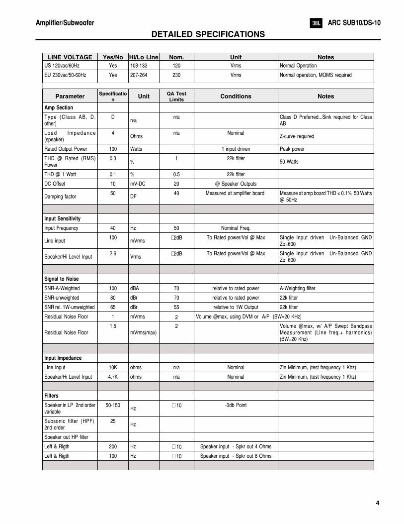
Left & Rigth 200 Hz � 10 Speaker input - Spkr out 4 Ohms
Left & Rigth 100 Hz � 10 Speaker input - Spkr out 8 Ohms
4
Amplifier/Subwoofer ARC SUB10/DS-10
Limiter
THD at Max. OutputPower
n/a n/a functionalMaximum Output Power
Maximum THD as a result of limiting.
Features —
V o l u m e p o t T a p e r(lin/log)
LOG— functional
HP Speaker out functional Refer to filter section
Input Configuration
Line In & LFE YES — functional LR dual RCA jack
Spkr/Hi Level In YES — functional Spring type connector
Signal Sensing (ATO)
Auto-Turn-On YES functional Auto - on selection switch in Auto Bicolor LED (Green=signal/ red= No signal)
ATO Input test frequency 40 Hz functional “
ATO Line level in 5 mV functional "
ATO Level Speaker in 50 mV functional "
ATO Turn-on time5
ms functionalAmp connected and AC on, then input signalapplied
Auto Mute/ Turn-OFFTime
15minutes
17 T before muting, after signal is removed Auto turn of time (T) must be 3 > T < 15Minutes
Power on Delay time 0.1 sec. 5 AC Power Applied
Transients/Pops
ATO Transient 5 mV-peak 50
Turn-on Transient 2 Vpk-pk 2 @ Speaker Outputs AC Line cycled from OFF to ON
Turn-off Transient 2 Vpk-pk 2 @ Speaker Outputs AC Line cycled from ON to OFF
Efficiency
Efficiency 65 % 64 Nominal Line voltage 120 VAC / 230 VAC
Stand-by Input Power15
Watts18 @ nom. line voltage Auto turn of time (T) must be 3 > T < 15
Minutes
Power Cons. @ ratedpower
76Watts
80 @ nom. line voltage75 Watts @ 4 Ohms nominal line voltage
Protection
Short Circuit ProtectionYES
functionalDirect short at output Amplifier should resume operation after short
circuit condition removal
Thermal Protection
YES
functional
@1/8 max unclipped Power IEC Noiseusing driver load
Temperature rise in accessible metal partsshould not exceed 35K rise for 120v versionor 30K rise for European versions (refer torequirements sheet).
Line Fuse Rating
US (120v) version Amps 0.6 Type-T or Slo Blo-250 V Internal fuse
EU Amps TBD Type-T or Slo Blo-250 V External fuse with UL/SEMKO rated holder
5
Amplifier/Subwoofer ARC SUB10/DS-10
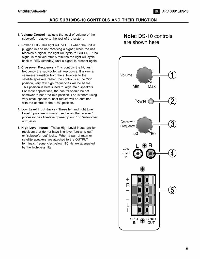
1. Volume Control - adjusts the level of volume of the
subwoofer relative to the rest of the system.
2. Power LED - This light will be RED when the unit is
plugged in and not receiving a signal; when the unit
receives a signal, the light will cycle to GREEN. If no
signal is received after 5 minutes the light will cycle
back to RED (standby) until a signal is present again.
3. Crossover Frequency - This controls the highest
frequency the subwoofer will reproduce. It allows a
seamless transition from the subwoofer to the
satellite speakers. When the control is at the “50”
position, very few high frequencies will be heard.
This position is best suited to large main speakers.
For most applications, the control should be set
somewhere near the mid position. For listeners using
very small speakers, best results will be obtained
with the control at the “150” position.
4. Low Level Input Jacks - These left and right Line
Level Inputs are normally used when the receiver/
processor has line-level “pre-amp out ” or “subwoofer
out” jacks.
5. High Level Inputs - These High Level Inputs are for
receivers that do not have line-level “pre-amp out”
or “subwoofer out” jacks. When a pair of main or
satellite speakers are attached to the OUTPUT
terminals, frequencies below 180 Hz are attenuated
by the high-pass filter.
6
Amplifier/Subwoofer ARC SUB10/DS-10
Min
50
Max
150
Volume
CrossoverFrequency
R
R
L
L
Power
SPKRIN
SPKROUT
LowLevel
In4
3
1
2
5
Note: DS-10 controlsare shown here
ARC SUB10/DS-10 CONTROLS AND THEIR FUNCTION
1. TROUBLE SHOOTING BEFORE OPENINGCheck connections, control settings, driver and other possible
external problems. If there is Output, determine if all controls
and Inputs function properly. Rotate Pots over full range while
applying lateral and vertical oscillating forces to locate possible
intermittent function. High Level Inputs should be tested
individually both differentially (signal from "-" to "+" with normal
output) and in common mode (signal from low level ground to
both "+" and "-" shorted together, giving virtually no output).
While passing a signal, corner drop the enclosure a few inches
to expose possible intermittent problems. Check woofer for
rubbing of voice coil or tears in cone or surround. Check
cabinet for loose extraneous articles which may have been
pushed into port.
2. REMOVING THE AMPLIFIER.
There are voltages and hot components at many points inthe amplifier which can, if contacted, cause personal injury.Be extremely careful. Any adjustments or serviceprocedures that require operation of the amplifier out of itsenclosure should be performed only by trained servicepersonnel. Refer to PCB drawings for locations of hazardsand familiarize yourself with their locations before starting.
A. Remove the subwoofer grille.
B. Remove the (4) 1” Black PPH screws attaching the
woofer to the cabinet.
C. Remove the woofer, unplug the two connecting wires.
D. Remove the (8) ¾” screws black pph screws
attaching the ampifier assembly to the cabinet.
E. Remove the ampifier assembly.
F. For access to the input panel, first remove the three
outer screws. Remove knob and nuts from
potentiometers. Cut away the sealant securing the
cover to the faceplate. The input PCB should now
pull out completely.
3. TROUBLE SHOOTING AFTER REMOVAL
Verify AC plug is disconnected. See WARNINGS in section2.
To prevent loose hardware from reducing safety spacings, itis essential that all hardware be replaced in the samemanner as it was removed, with lock washers under all nuts,proper torque on screws and thread locking sealer on thetransformer nuts.
If line core or strain relief are replaced, it is necessary toseal them completely to panel with an approved conformalcoating to prevent air "whistling" through any openings fromwoofer pressure.
To reduce the risk or electric shock and/or fire,replace items as marked on schematic with thesafety marking only with the exact replacementslisted in the safety component list, page 2. Ifexact replacements are not available, order them from thefactory or an authorized service center.
A. Check fuse F1. If blown visually check transformer for
discoloration, and large capacitors (C1, C2) for bulges
or venting. Check for shorts with an Ohmmeter,
(see schematic).
B. With ohmmeter, verify voice coil of woofer is 3.9
ohms, and windings of transformer are continuous.
C. Examine board and wiring for obvious damage,
broken or poorly soldered connections, or
discoloration.
D. Repair or replace items identified above.
E. For live power testing, attach a 4 ohm 100 watt
resistor to the output wires.
F. If the LED is not on, check for fuse continuity and
then for cold solder joints on CMC1 and bridge diode.
G. With a signal present at the input, the output to the
power amp is at pin #8 of U1. If the signal is not
present at pin 8, there is a problem with preamp
section. Most likely, a cold solder joint will be the
7
Amplifier/Subwoofer ARC SUB10/DS-10
CAUTIONS AND WARNINGS
BEFORE THIS AMPLIFIER IS PLUGGED IN, make sure its rated voltage corresponds to the voltage of the AC powersource to be employed. Failure to use the correct voltage could cause damage to the amplifier when the AC powercable is plugged in. Do not exceed the rated voltage by more than 10%; operation below 90% will degradeperformance or cause the unit to shut off.
problem. Track back the signal path to locate
problem.
H. If signal present at pin 8, but still no sound, check
for cold solder joints on all power resistors, R4a and
R4b and the the power amp module. If C24 is
blown, C6 is not soldered or is defective. Check the
signal at R2. On the down signal side, the voltage
signal should be very small. If signal is similar on
both sides of R2, the amp module is likely defective.
I. If you hear a mechanical clicking noise from the amp
module, this indicates that the short circuit protection
has been engaged. Check that Q3, Q4 and Q5 are
soldered correctly. Also check that Q3 is not shorted
to power amp case.
J. If you have to replace the power module, be very,
very patient with the solder removal from this single
sided PCB. COMPLETELY REMOVE SOLDER
BEFORE TRYING TO REMOVE THE MODULE!
(See page 23)
K. Assembly notes. Top side soldering as below:
J5: solder both ends
J3: solder both ends
J1: solder both ends
R48: solder GND end
At junction of C7a/C7b: Pin to GND
Crossover pot Gnd wire from PDB pad to POT
barrel. (Only physical contact required between
pot body and faceplate).
After repair, inspect for possible safety hazards, includingloose hardware, missing lock washers, correct fuse andlead dress of primary wires (these must be held in positionwith cable ties so that they cannot touch secondarycomponents). With ohmmeter, check that panel isconnected to signal ground.
It is essential that the following safety insulation test beperformed prior to returning the Power SubWoofer to thecustomer, using one of the following methods.
A) Insulation Resistance Test
With a 500VDC Insulation Tester, Checkinsulation from the outer metal contact of the
RCA jack (chassis) to the line neutral of AC
cord. Resistance should be >100M� .
B) Hi-Pot Test
If a UL approved Hi-Pot tester is available, testline & neutral of AC cord to outer shell of RCAjack (chassis) at 1100VAC for 2 seconds.Observe all of instrument manufacturer'sinstructions and safety warnings in performingthis test.
Connect subwoofer system to a music source. Play at highlevel while checking for air leaks around panel edge, driver,panel jacks and controls, and voice coil problems such asrubbing or loose turns. With the crossover "frequency" setto 50Hz, very little of the voice content should be heard.
4. REASSEMBLYFollow all disassembly instructions in reverse order. If theinput plate has been removed, it must be re-sealed with asmall bead of silicon seal or air leaks may result.
8
Amplifier/Subwoofer ARC SUB10/DS-10
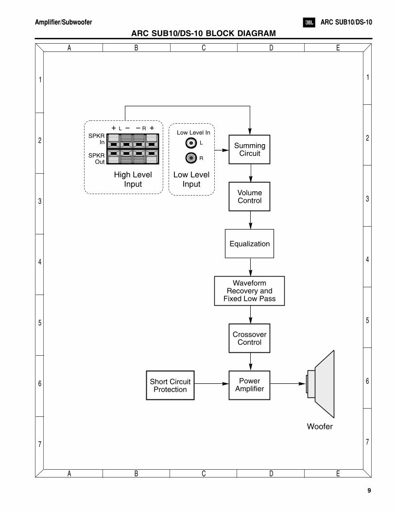
ARC SUB10/DS-10 BLOCK DIAGRAM
9
Amplifier/Subwoofer ARC SUB10/DS-10
SummingCircuit
VolumeControl
Equalization
WaveformRecovery and
Fixed Low Pass
CrossoverControl
PowerAmplifier
Short CircuitProtection
Woofer
L R
SPKRIn
SPKROut
High LevelInput
Low Level In
R
L
Low LevelInput
E
E
D
D
C
C
B
B
A
A
7 7
6 6
5 5
4 4
3 3
2 2
1 1
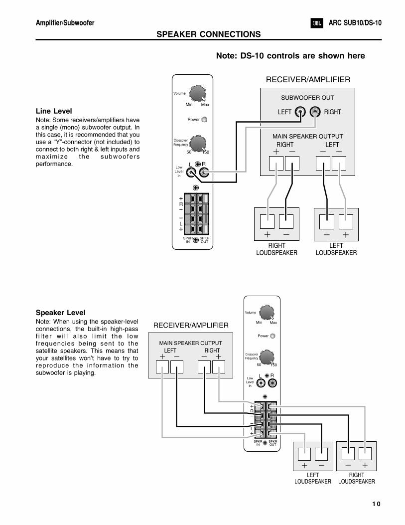
SPEAKER CONNECTIONS
Line LevelNote: Some receivers/amplifiers havea single (mono) subwoofer output. Inthis case, it is recommended that youuse a “Y”-connector (not included) toconnect to both right & left inputs andmax imize the subwoofersperformance.
Speaker LevelNote: When using the speaker-levelconnections, the built-in high-passf i l te r w i l l a lso l im i t the lowfrequencies being sent to thesatellite speakers. This means thatyour satellites won't have to try toreproduce the information thesubwoofer is playing.
1 0
Amplifier/Subwoofer ARC SUB10/DS-10
Min
50
Max
150
Volume
CrossoverFrequency
R
R
L
L
Power
SPKRIN
SPKROUT
LowLevel
In
RIGHTLOUDSPEAKER
LEFTLOUDSPEAKER
MAIN SPEAKER OUTPUT
SUBWOOFER OUT
LEFT
LEFT
RIGHT
RIGHT
RECEIVER/AMPLIFIER
Min
50
Max
150
Volume
CrossoverFrequency
R
R
L
L
Power
SPKRIN
SPKROUT
LowLevel
In
RIGHTLOUDSPEAKER
LEFTLOUDSPEAKER
MAIN SPEAKER OUTPUT
LEFT RIGHT
RECEIVER/AMPLIFIER
Note: DS-10 controls are shown here
TROUBLESHOOTING
If you used the high-level (speaker) inputs and
there is no sound from any of the speakers, check
the following:
� Receiver/amplifier is on and a source is playing.
� Powered subwoofer is plugged in.
� Check all wires and connections between
receiver/amplifier and speakers. Make sure all wires
are connected. Make sure none of the speaker
wires are frayed, cut or punctured.
� Review proper operation of your receiver/amplifier.
If there is low bass output, check the following:
� Make sure the connections to the left and right
“Speaker Inputs” have the correct polarity (+ and –).
� Make sure that the subwoofer is plugged into an
active electrical outlet.
� Adjust the crossover point.
� If you are using a Dolby* Digital/DTS� receiver or
processor, make sure that the subwoofer
adjustments on the receiver/processor are set up
correctly.
� Slowly turn the level Control clockwise until you
begin to hear the desired amount of bass.
If you used the line-level inputs and there is no
sound from the subwoofer, check the following:
� Receiver/amplifier is on and a source is playing.
� Powered subwoofer is plugged in.
� Check all wires and connections between receiver/
amplifier and subwoofer. Make sure all wires are
connected. Make sure none of the wires are frayed,
cut or punctured.
� Review proper operation of your receiver/amplifier.
1 1
Amplifier/Subwoofer ARC SUB10/DS-10
General Function
UUT = Unit Under Test
1. Connect both right and left line level inputs (RCA) to signal generator and UUT. Use Y-cable if necessary frommono source. VOLUME control should be full counterclockwise.
2. Turn on generator, adjust to 50mV, 50 Hz.
3. Plug in UUT; red LED should be ON. Turn VOLUME control full clockwise.
4. LED should turn Green; immediate bass response should be heard and felt from port tube opening.
5. Turn off generator, turn VOLUME control fully counterclockwise, disconnect RCA cables.
6. Connect one pair of speaker cables to either high level input terminal on UUT. Cables should be connected toan integrated amplifier fed by the signal generator.
7. Turn on generator and adjust so that speaker level output is 2.0V, 50 Hz. Turn VOLUME control full clockwise.
8. Green LED should light, immediate bass response should be heard and felt from the port tube opening.
Sweep Function
1. Follow steps 1-4 above, using a sweep generator as a signal source.
2. Sweep generator from 20Hz to 300Hz. Listen to the cabinet and drivers for any rattles, clicks, buzzes or anyother noises. If any unusual noises are heard, remove driver and test.
Driver Function
1. Remove driver from cabinet; detach + and - wire clips.
2. Check DC resistance of driver; it should be 3.2 to 3.9 ohms.
3. Connect a pair of speaker cables to driver terminals. Cables should be connected to an integrated amplifier fed bya signal generator and adjust so that speaker level output is 5.0V.
4. Sweep generator from 20Hz to 1kHz. Listen to driver for any rubbing, buzzing, or other unusual noises.
1 2
Amplifier/Subwoofer ARC SUB10/DS-10
ARC SUB10 / DS-10 TEST SET UP AND PROCEDURE
AMPLIFIER
CD PLAYER
PRE AMP
AC VOLT METER ( 6V )
ARC SUB10 / DS-10UNDER TESTLINE LEVEL
SPEAKER LEVEL
Min
50
Max
150
Volume
CrossoverFrequency
R
R
L
L
Power
SPKRIN
SPKROUT
LowLevel
In
FROM LINE-LEVELSOURCE
SPEAKER OUTPUTFROM AMPLIFIER
1 3
Amplifier/Subwoofer ARC SUB10/DS-10
ARC SUB10 / DS-10 POWER AMP MODULE TESTING FLOW CHART
No
Yes
No
Yes
No
Yes
No
Yes
No
No Yes
Yes
H No
Yes No
Yes
START
Check V+,V-, +/-15V voltage to
module
Check fusetransformer,
CMC,rectifier, C1,
C2
Checkswitchingfrequency100KHz +/-10%~1Vpp
Check I/P ofmodule to
GND 0V D.C.
Power up withno signal I/PLED RED
OK
OK
OK
OK
OK
OK
OK
OK
Check C12and Pre-AMP Check O/P to
module for80Vpp square
wavemeasure to
GND
Check L1,L2, C6, C24
Check 6V tomodule
measure to V-
ReplaceModule
Power AMPOK
END
Check D1,R1, Q3, Q4,Q5 and SCP
Checktransformer,
CMC,rectifier, C1,C2, D9, D10,
R16, R17
Check S/Dvoltage tomodule (5V)measure to V-
Check D6,R9, R46
Resistancecheckbetween V+V- and O/PO/P to GNDshould > 5K
SERVICE BULLETIN JBL9903 - APRIL 1999
To all JBL Service Centers This considered a Minor repairModel: ARC SUB10 / DS-10
Subject: Check Solder Joints in Event of Failure
Some performance related complaints in the ARC SUB10 / DS-10 powered subwoofer may be caused by coldSolder connections between the 28 pins of the Power Amp Module and the main circuit board. Whentroubleshooting, failure to check these joints can result in erroneous conclusions or wasted time.
In the event you receive a ARC SUB10 / DS-10 Subwoofer with the complaints “Dead, or No Output, or
Motorboating (Oscillation)”, perform the steps listed below first before any further troubleshooting takes
place:
1) Unplug all cables, lay the subwoofer on a padded surface.
2) Remove all Philips screws around the outer perimeter of the amplifier faceplate.
3) Remove amplifier assembly; you should be able to remove the amplifier far enough out of the cabinet toservice it without removing the woofer wires.
4) Locate the Power Amp Module; it is the large gray component with a metal case. On the Solder side of thecircuit board are the 28 Solder connections to the Module.
5) Regardless of whether you can visibly see breaks in any of the connections or not, carefully re-Solder all 28pin connections, adding 60/40 rosin core Solder. Take care not “bridge” any connections on the board withSolder.
6) Inspect the Solder joints to the main filter capacitors C1 and C2 on the main PCB and re-Solder if needed.
7) Replace the amplifier assembly back into the cabinet; replace the screws.
8) Test the unit by applying a signal from a music source, adjust the volume to a moderate level and confirm theoriginal problem has been corrected.
1 4
Amplifier/Subwoofer ARC SUB10/DS-10
SERVICE BULLETIN JBL2000-01 - JANUARY 2000
To all JBL Service Centers Warranty labor rate: MINOR repairModel: ARC SUB10 / DS-10
Subject: Failure of C6
In the event you receive a JBL subwoofer corresponding to one of the above models with the complaint “no output” andcapacitor C6 (10uf 50v NPE) is damaged in the amplifier, replace with the following part: JBL part# 30712 (10uf 100v NPE)
General reference for location only; not all parts or designators may conform to these drawings
It is also recommended following the repair that the instructions included in bulletin #JBL9903 are followed.
Models Serial number 120/230V Status Action
ARC SUB10 / DS-10 All serial numbers affected Replace if damaged Replace C6 with JBL part# 30712
1 5
Amplifier/Subwoofer ARC SUB10/DS-10
TROUBLESHOOTING TIPS AND SOLUTIONS TO COMMON SERVICE PROBLEMS
For models: ARC SUB 8, ARC SUB 10 TIP# JBLTT2000-01
Complaint:
How do you replace or service any of the front panel components on the Subwoofer faceplate for model ARCSUB 10 ?
Probable Cause:
The High level Input terminals, potentiometers, RCA jack, and switch(es) are behind a sealed cover to protect theair-tight integrity of the cabinet enclosure.
Solution:
1) Unplug all external cables from the subwoofer; place the cabinet on a padded surface.
2) Remove any subwoofer grille; remove the woofer from the cabinet. Detach the two connections from thewoofer terminals.
3) Remove all Phillips screws holding the amplifier to the cabinet; remove the amplifier.
4) Remove all knobs, nuts, and Philips screws from the outer control section of the amplifier faceplate.
5) Locate the sealed cover on the inside of the amplifier faceplate (see illustration); the bead of adherent mustbe broken to remove the main PCB with front panel components from the plastic faceplate. This is mosteasily accomplished by CAREFULLY using a box cutter, exacto knife, or similar sharp instrument. First scrapeall excess material from the three surfaces; then force the blade into the groove between the rear cover andthe faceplate. DO NOT attempt to remove the rear cover from the main PCB.
6) When enough material is removed, the main PCB with cover can be pulled away from the faceplate,exposing the components.
7) After servicing, a bead of “silicon seal” or similar adherent must be applied to all surfaces where it wasremoved. Reassemble the rest of the components in reverse order.
1 6
Amplifier/Subwoofer ARC SUB10/DS-10
1 7
Amplifier/Subwoofer ARC SUB10/DS-10
CABINET EXPLODED VIEWS
ARC SUB10 CABINETEXPLODED VIEW
DS-10 CABINETEXPLODED VIEW
SCREWS (4X)
SCREWS (4X)
SCREWS (4X)
WOOFER TRIMRING #201060
10" WOOFER#200500
10" WOOFER#201000
KICKPLATEwith LOGO#201070
GRILLE#200110
GRILLE#201010
GRILLERETAINERCUPS (4)#201080
GRILLERETAINER
CUPS (4)#201080
CABINET(NOT FOR SALE)
CABINET(NOT FOR SALE)
AMP ASSEMBLY(NOT FOR SALE)
AMP ASSEMBLY(NOT FOR SALE)
SCREWS (8X)ARCSUB10 LABEL#200160
DS-10 LABEL#201150
SCREWS (8X)
TO
REDUCETHERISKOFELECTRIC
SHOCK.DO
NOT
EXPOSETHISEQUIPMENTTO
RAIN
OR
MOISTURE
CAUTION
RISKOFELECTRIC
SHOCK
DO
NOTOPEN
TO
REDUCETHERISKOFELECTRIC
SHOCK.DO
NOT
EXPOSETHISEQUIPMENTTO
RAIN
OR
MOISTURE
CAUTION
RISKOFELECTRIC
SHOCK
DO
NOTOPEN
~120VAC
60Hz
110W
~120VAC
60Hz
110W
DiscreteDigitalAMPLIFICATION
DiscreteDigitalAMPLIFICATION
ARC
SUB
8
ARC
SUB
8
ARC
SUB
8
ARC
SUB
8
SerialNo.
XXXXXX-XXXXX
SerialNo.
XXXXXX-XXXXX
JBL
CO
NSUM
ER
PRO
DUCTS,INC.
NO
RTHRIDG
E,CA
M
ADE
IN
CANADA
JBL
CO
NSUM
ER
PRO
DUCTS,INC.
NO
RTHRIDG
E,CA
M
ADE
IN
CANADA
Low
LevelIn
Low
LevelIn
R
R
L
L
L
L
R
R
Power
Power
SPKR
In
SPKR
In
SPKR
Out
SPKR
Out
50
50
Min
Min
150
150
Max
Max
Volume
Volume
CrossoverFrequency
CrossoverFrequency
NRTL
NRTL
LR
110113
LR
110113
1 8
Amplifier/Subwoofer ARC SUB10/DS-10
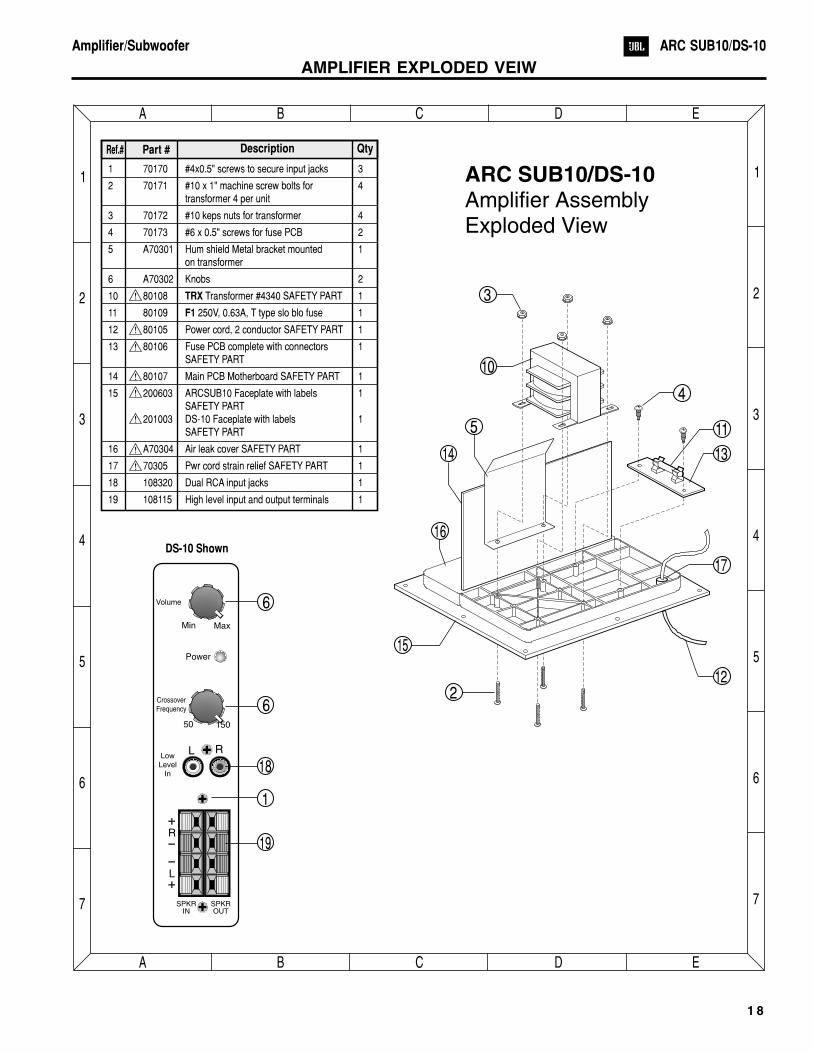
AMPLIFIER EXPLODED VEIW
E
E
D
D
C
C
B
B
A
A
7 7
6 6
5 5
4 4
3 3
2 2
1 1
Min
50
Max
150
Volume
CrossoverFrequency
R
R
L
L
Power
SPKRIN
SPKROUT
LowLevel
In
Ref.# Part # Description Qty
1 70170 #4x0.5" screws to secure input jacks 3
2 70171 #10 x 1" machine screw bolts for 4transformer 4 per unit
3 70172 #10 keps nuts for transformer 4
4 70173 #6 x 0.5" screws for fuse PCB 2
5 A70301 Metal bracket mounted 1on transformer
6 A70302 2
10 80108 Transformer #4340 SAFETY PART 1
11 80109 250V, 0.63A, T type slo blo fuse 1
12 80105 Power cord, 2 conductor SAFETY PART 1
13 80106 Fuse PCB complete with connectors 1SAFETY PART
14 80107 Motherboard SAFETY PART 1
15 200603 ARCSUB10 Faceplate with labels 1SAFETY PART
201003 DS-10
16 A70304 Air leak cover SAFETY PART 1
17 70305 Pwr cord strain relief SAFETY PART 1
18 108320 Dual RCA input jacks 1
19 High level input and output terminals 1
TRX
F1
Hum shield
Knobs
Main PCB
Faceplate with labels 1SAFETY PART
108115
ARC SUB10/DS-10Amplifier AssemblyExploded View
2
18
6
6
1
19
15
16
14
5
10
3
4
13
11
17
12
DS-10 Shown
1 9
Amplifier/Subwoofer ARC SUB10/DS-10
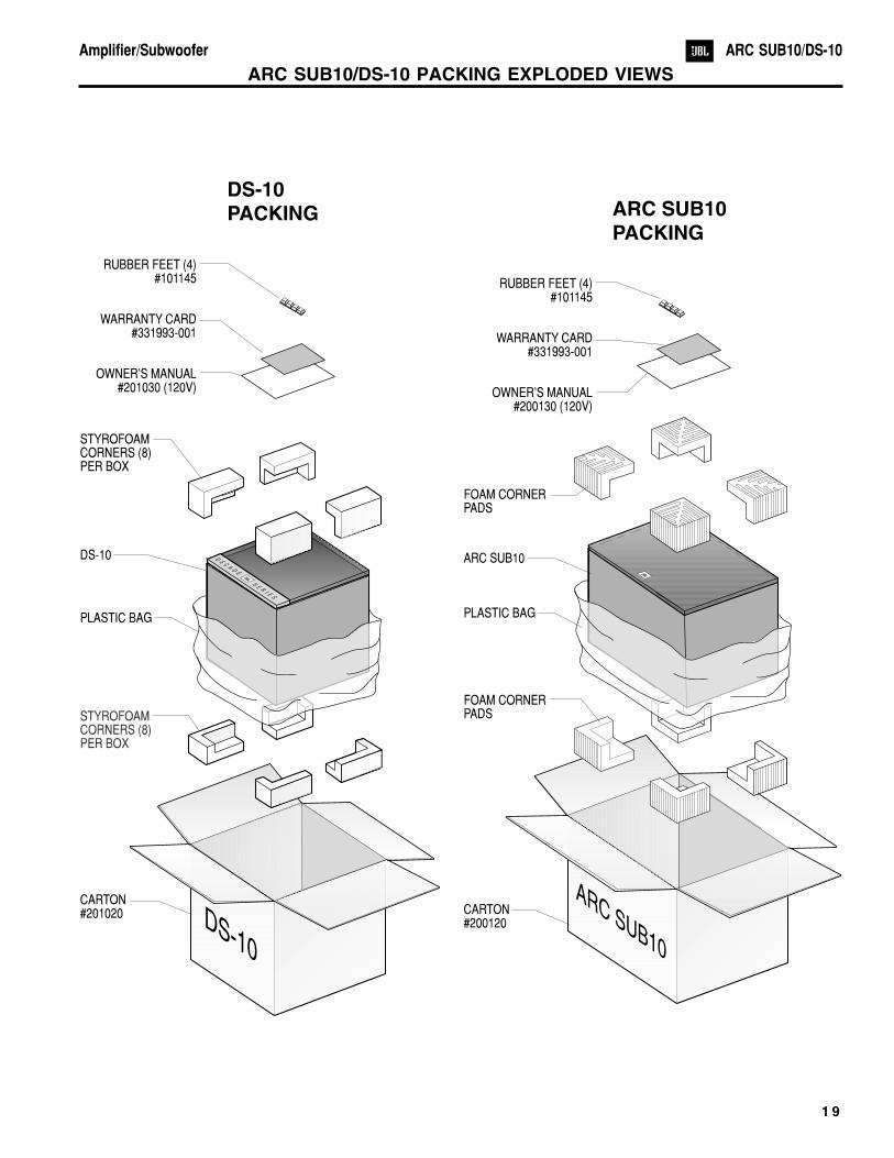
ARC SUB10/DS-10 PACKING EXPLODED VIEWS
ARC SUB10
DE
CA
DE
SE
RI E
S
DS-10PACKING ARC SUB10
PACKING
DS-10
RUBBER FEET (4)#101145
WARRANTY CARD
OWNER'S MANUAL#201030 (120V)
#331993-001
RUBBER FEET (4)#101145
WARRANTY CARD
OWNER'S MANUAL#200130 (120V)
#331993-001
FOAM CORNERPADS
FOAM CORNERPADS
ARC SUB10
CARTON#200120
CARTON#201020
PLASTIC BAG
STYROFOAMCORNERS (8)PER BOX
DS-10
STYROFOAMCORNERS (8)PER BOX
PLASTIC BAG
2 0
Amplifier/Subwoofer ARC SUB10/DS-10
ARC SUB10 Version 5 PCB
E
E
D
D
C
C
B
B
A
A
7 7
6 6
5 5
4 4
3 3
2 2
1 1PLAIN 5 - Component Side Trace
PLAIN 5 - Solder Side Trace Layer as viewed through the board
The PLAIN 5 PCB was used in ARCSUB10
2 1
Amplifier/Subwoofer ARC SUB10/DS-10
ARC SUB10/DS-10 Version 5.1 PCB
PLAIN 5.1 - Component Side Trace
PLAIN 5.1 - Solder Side Trace Layer as viewed through the board
E
E
D
D
C
C
B
B
A
A
7 7
6 6
5 5
4 4
3 3
2 2
1 1
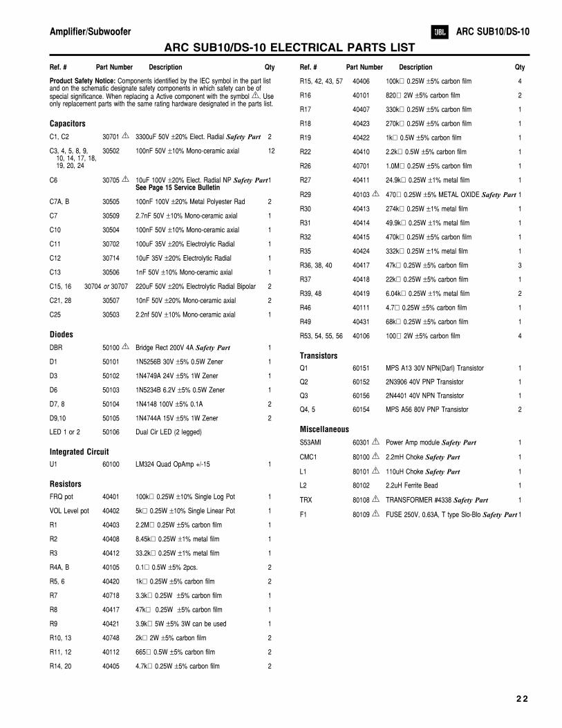
ARC SUB10/DS-10 ELECTRICAL PARTS LIST
Product Safety Notice: Components identified by the IEC symbol in the part listand on the schematic designate safety components in which safety can be ofspecial significance. When replacing a Active component with the symbol . Useonly replacement parts with the same rating hardware designated in the parts list.
R29 40103 470� 0.25W �5% METAL OXIDE Safety Part 1
R30 40413 274k� 0.25W �1% metal film 1
R31 40414 49.9k� 0.25W �1% metal film 1
R32 40415 470k� 0.25W �5% carbon film 1
R35 40424 332k� 0.25W �1% metal film 1
R36, 38, 40 40417 47k� 0.25W �5% carbon film 3
R37 40418 22k� 0.25W �5% carbon film 1
R39, 48 40419 6.04k� 0.25W �1% metal film 2
R46 40111 4.7� 0.25W �5% carbon film 1
R49 40431 68k� 0.25W �5% carbon film 1
R53, 54, 55, 56 40106 100� 2W �5% carbon film 4
Transistors
Q1 60151 MPS A13 30V NPN(Darl) Transistor 1
Q2 60152 2N3906 40V PNP Transistor 1
Q3 60156 2N4401 40V NPN Transistor 1
Q4, 5 60154 MPS A56 80V PNP Transistor 2
Miscellaneous
S53AMI 60301 Power Amp module Safety Part 1
CMC1 80100 2.2mH Choke Safety Part 1
L1 80101 110uH Choke Safety Part 1
L2 80102 2.2uH Ferrite Bead 1
TRX 80108 TRANSFORMER #4338 Safety Part 1
F1 80109 FUSE 250V, 0.63A, T type Slo-Blo Safety Part 1
2 2
Amplifier/Subwoofer ARC SUB10/DS-10
Ref. # Part Number Description Qty Ref. # Part Number Description Qty
2 3
Amplifier/Subwoofer ARC SUB10/DS-10
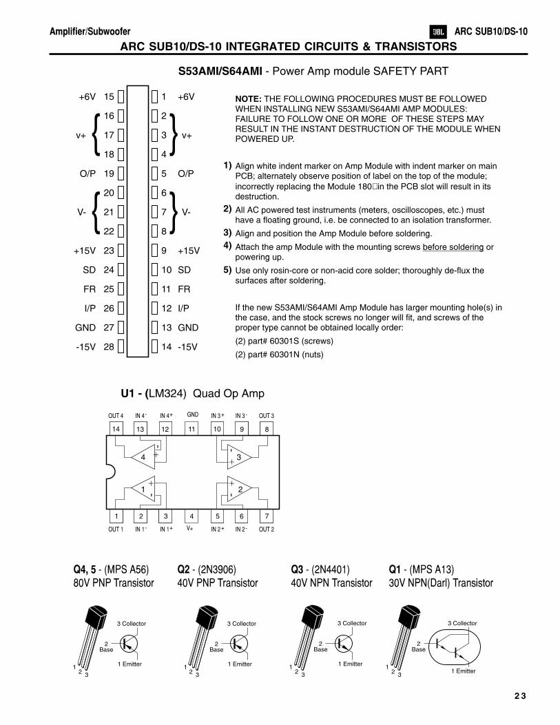
ARC SUB10/DS-10 INTEGRATED CIRCUITS & TRANSISTORS
U1 - (LM324) Quad Op Amp
1 52 63 74
14 1013 912 811
1 2
4 3
- -
- -
+ +
+ +
OUT 4
OUT 1
IN 4-
IN 1-
IN 4+
IN 1+
GND
V+
IN 3 +
IN 2 +
IN 3-
IN 2-
OUT 3
OUT 2
2Base
2Base
3 Collector 3 Collector
1 Emitter 1 Emitter1 1
2 23 3
Q4, 5 - (MPS A56)80V PNP Transistor
Q2 - (2N3906)40V PNP Transistor
2Base
2Base
3 Collector 3 Collector
1 Emitter1 Emitter
1 12 2
3 3
Q3 - (2N4401)40V NPN Transistor
Q1 - (MPS A13)30V NPN(Darl) Transistor
S53AMI/S64AMI - Power Amp module SAFETY PART
15
16
17
18
19
20
21
22
23
24
25
26
27
28
1
2
3
4
5
6
7
8
9
10
11
12
13
14
+6V
v+
O/P
V-
+15V
SD
FR
I/P
GND
-15V
+6V
v+
O/P
V-
+15V
SD
FR
I/P
GND
-15V
NOTE: THE FOLLOWING PROCEDURES MUST BE FOLLOWEDWHEN INSTALLING NEW S53AMI/S64AMI AMP MODULES:FAILURE TO FOLLOW ONE OR MORE OF THESE STEPS MAYRESULT IN THE INSTANT DESTRUCTION OF THE MODULE WHENPOWERED UP.
Align white indent marker on Amp Module with indent marker on mainPCB; alternately observe position of label on the top of the module;
incorrectly replacing the Module 180 in the PCB slot will result in itsdestruction.
All AC powered test instruments (meters, oscilloscopes, etc.) musthave a floating ground, i.e. be connected to an isolation transformer.
Align and position the Amp Module before soldering.
Attach the amp Module with the mounting screws orpowering up.
Use only rosin-core or non-acid core solder; thoroughly de-flux thesurfaces after soldering.
If the new S53AMI/S64AMI Amp Module has larger mounting hole(s) inthe case, and the stock screws no longer will fit, and screws of theproper type cannot be obtained locally order: