52
Aerowave Processes Description R TIG (GTAW) Welding Stick (SMAW) Welding Arc Welding Power Source OM-319 154754H September 2000 Visit our website at www.MillerWelds.com

Aerowave
Processes
Description
�
TIG (GTAW) Welding
Stick (SMAW) Welding
Arc Welding Power Source
OM-319 154754H
September 2000
Visit our website at
www.MillerWelds.com

Miller Electric manufactures a full lineof welders and welding related equipment.For information on other quality Millerproducts, contact your local Miller distributorto receive the latest full line catalog orindividual catalog sheets. To locate your nearestdistributor or service agency call 1-800-4-A-Miller,or visit us at www.MillerWelds.com on the web.
Thank you and congratulations on choosing Miller. Nowyou can get the job done and get it done right. We knowyou don’t have time to do it any other way.
That’s why when Niels Miller first started building arcwelders in 1929, he made sure his products offeredlong-lasting value and superior quality. Like you, hiscustomers couldn’t afford anything less. Miller productshad to be more than the best they could be. They had tobe the best you could buy.
Today, the people that build and sell Miller products continue thetradition. They’re just as committed to providing equipment and servicethat meets the high standards of quality and value established in 1929.
This Owner’s Manual is designed to help you get the most out of yourMiller products. Please take time to read the Safety precautions. They willhelp you protect yourself against potential hazards on the worksite. We’ve
made installation and operation quick and easy.With Miller you can count on years of reliableservice with proper maintenance. And if forsome reason the unit needs repair, there’s aTroubleshooting section that will help youfigure out what the problem is. The parts listwill then help you to decide which exact partyou may need to fix the problem. Warranty andservice information for your particular modelare also provided.
Miller is the first weldingequipment manufacturer inthe U.S.A. to be registered tothe ISO 9001 Quality SystemStandard.
Working as hard as you do– every power source fromMiller is backed by the mosthassle-free warranty in thebusiness.
From Miller to You
Miller offers a TechnicalManual which providesmore detailed service andparts information for yourunit. To obtain a TechnicalManual, contact your localdistributor. Your distributorcan also supply you withWelding Process Manualssuch as SMAW, GTAW,GMAW, and GMAW-P.

The following terms areused interchangeablythroughout this manual:TIG = GTAWStick = SMAW
TABLE OF CONTENTS
SECTION 1 – SAFETY PRECAUTIONS - READ BEFORE USING 1. . . . . . . . . . . . . . . . . . . . . . . . . . . . 1-1. Symbol Usage 1. . . . . . . . . . . . . . . . . . . . . . . . . . . . . . . . . . . . . . . . . . . . . . . . . . . . . . . . . . . . . . . . 1-2. Arc Welding Hazards 1. . . . . . . . . . . . . . . . . . . . . . . . . . . . . . . . . . . . . . . . . . . . . . . . . . . . . . . . . . 1-3. Additional Symbols for Installation, Operation, and Maintenance 3. . . . . . . . . . . . . . . . . . . . . . 1-4. Principal Safety Standards 3. . . . . . . . . . . . . . . . . . . . . . . . . . . . . . . . . . . . . . . . . . . . . . . . . . . . . 1-5. EMF Information 4. . . . . . . . . . . . . . . . . . . . . . . . . . . . . . . . . . . . . . . . . . . . . . . . . . . . . . . . . . . . . .
SECTION 1 – CONSIGNES DE SECURITE – LIRE AVANT UTILISATION 5. . . . . . . . . . . . . . . . . . . . . 1-1. Signification des symboles 5. . . . . . . . . . . . . . . . . . . . . . . . . . . . . . . . . . . . . . . . . . . . . . . . . . . . . 1-2. Dangers relatifs au soudage à l’arc 5. . . . . . . . . . . . . . . . . . . . . . . . . . . . . . . . . . . . . . . . . . . . . . 1-3. Dangers supplémentaires en relation avec l’installation, le fonctionnement
et la maintenance 7. . . . . . . . . . . . . . . . . . . . . . . . . . . . . . . . . . . . . . . . . . . . . . . . . . . . . . . . . . . . . 1-4. Principales normes de sécurité 8. . . . . . . . . . . . . . . . . . . . . . . . . . . . . . . . . . . . . . . . . . . . . . . . . . 1-5. Information sur les champs électromagnétiques 8. . . . . . . . . . . . . . . . . . . . . . . . . . . . . . . . . . . .
SECTION 2 – INSTALLATION 9. . . . . . . . . . . . . . . . . . . . . . . . . . . . . . . . . . . . . . . . . . . . . . . . . . . . . . . . . . . 2-1. Specifications 9. . . . . . . . . . . . . . . . . . . . . . . . . . . . . . . . . . . . . . . . . . . . . . . . . . . . . . . . . . . . . . . . 2-2. Dimensions And Weights 9. . . . . . . . . . . . . . . . . . . . . . . . . . . . . . . . . . . . . . . . . . . . . . . . . . . . . . . 2-3. Duty Cycle And Overheating 10. . . . . . . . . . . . . . . . . . . . . . . . . . . . . . . . . . . . . . . . . . . . . . . . . . . . 2-4. Volt-Ampere Curves 10. . . . . . . . . . . . . . . . . . . . . . . . . . . . . . . . . . . . . . . . . . . . . . . . . . . . . . . . . . . 2-5. Selecting A Location 11. . . . . . . . . . . . . . . . . . . . . . . . . . . . . . . . . . . . . . . . . . . . . . . . . . . . . . . . . . . 2-6. 115 VAC Receptacle, Circuit Breaker, And Shielding Gas Connections 12. . . . . . . . . . . . . . . . . 2-7. Weld Output Terminals And Selecting Cable Sizes 12. . . . . . . . . . . . . . . . . . . . . . . . . . . . . . . . . . 2-8. Remote 14 Receptacle Information 13. . . . . . . . . . . . . . . . . . . . . . . . . . . . . . . . . . . . . . . . . . . . . . . 2-9. Electrical Service Guide 13. . . . . . . . . . . . . . . . . . . . . . . . . . . . . . . . . . . . . . . . . . . . . . . . . . . . . . . . 2-10. Placing Jumper Links 14. . . . . . . . . . . . . . . . . . . . . . . . . . . . . . . . . . . . . . . . . . . . . . . . . . . . . . . . . . 2-11. Connecting Input Power 15. . . . . . . . . . . . . . . . . . . . . . . . . . . . . . . . . . . . . . . . . . . . . . . . . . . . . . . . 2-12. Connecting To Automation Connector Receptacle RC12 16. . . . . . . . . . . . . . . . . . . . . . . . . . . . .
SECTION 3 – OPERATION 17. . . . . . . . . . . . . . . . . . . . . . . . . . . . . . . . . . . . . . . . . . . . . . . . . . . . . . . . . . . . . 3-1. Controls 17. . . . . . . . . . . . . . . . . . . . . . . . . . . . . . . . . . . . . . . . . . . . . . . . . . . . . . . . . . . . . . . . . . . . . 3-2. Polarity Switch And Pilot Lights 17. . . . . . . . . . . . . . . . . . . . . . . . . . . . . . . . . . . . . . . . . . . . . . . . . . 3-3. Mode Switch 18. . . . . . . . . . . . . . . . . . . . . . . . . . . . . . . . . . . . . . . . . . . . . . . . . . . . . . . . . . . . . . . . . 3-4. Amperage/Preset Meter And Voltmeter 18. . . . . . . . . . . . . . . . . . . . . . . . . . . . . . . . . . . . . . . . . . . 3-5. Output Switch And Pilot Light 18. . . . . . . . . . . . . . . . . . . . . . . . . . . . . . . . . . . . . . . . . . . . . . . . . . . 3-6. Amperage Adjustment Controls 19. . . . . . . . . . . . . . . . . . . . . . . . . . . . . . . . . . . . . . . . . . . . . . . . . 3-7. Examples Of Combination Remote Amperage Control 20. . . . . . . . . . . . . . . . . . . . . . . . . . . . . . . 3-8. AC Balance Control 21. . . . . . . . . . . . . . . . . . . . . . . . . . . . . . . . . . . . . . . . . . . . . . . . . . . . . . . . . . . 3-9. AC Frequency Controls 21. . . . . . . . . . . . . . . . . . . . . . . . . . . . . . . . . . . . . . . . . . . . . . . . . . . . . . . . 3-10. Postflow Time Control 22. . . . . . . . . . . . . . . . . . . . . . . . . . . . . . . . . . . . . . . . . . . . . . . . . . . . . . . . . 3-11. Start Switch 22. . . . . . . . . . . . . . . . . . . . . . . . . . . . . . . . . . . . . . . . . . . . . . . . . . . . . . . . . . . . . . . . . . 3-12. Power Switch 22. . . . . . . . . . . . . . . . . . . . . . . . . . . . . . . . . . . . . . . . . . . . . . . . . . . . . . . . . . . . . . . . 3-13. Optional Controls 23. . . . . . . . . . . . . . . . . . . . . . . . . . . . . . . . . . . . . . . . . . . . . . . . . . . . . . . . . . . . . 3-14. GTAW Trigger Hold Switch (Optional) 23. . . . . . . . . . . . . . . . . . . . . . . . . . . . . . . . . . . . . . . . . . . . 3-15. Spot Time Controls (Optional) 24. . . . . . . . . . . . . . . . . . . . . . . . . . . . . . . . . . . . . . . . . . . . . . . . . . . 3-16. Preflow Time Controls (Optional) 24. . . . . . . . . . . . . . . . . . . . . . . . . . . . . . . . . . . . . . . . . . . . . . . . 3-17. Initial Sequence Controls (Optional) 24. . . . . . . . . . . . . . . . . . . . . . . . . . . . . . . . . . . . . . . . . . . . . . 3-18. Pulser Controls (Optional) 25. . . . . . . . . . . . . . . . . . . . . . . . . . . . . . . . . . . . . . . . . . . . . . . . . . . . . . 3-19. Final Sequence Controls (Optional) 25. . . . . . . . . . . . . . . . . . . . . . . . . . . . . . . . . . . . . . . . . . . . . . 3-20. Pulsed Weld Waveforms 26. . . . . . . . . . . . . . . . . . . . . . . . . . . . . . . . . . . . . . . . . . . . . . . . . . . . . . .
SECTION 4 – MAINTENANCE & TROUBLESHOOTING 27. . . . . . . . . . . . . . . . . . . . . . . . . . . . . . . . . . . . 4-1. Routine Maintenance 27. . . . . . . . . . . . . . . . . . . . . . . . . . . . . . . . . . . . . . . . . . . . . . . . . . . . . . . . . . 4-2. Overload Protection And Adjusting Spark Gap 28. . . . . . . . . . . . . . . . . . . . . . . . . . . . . . . . . . . . . 4-3. Troubleshooting 29. . . . . . . . . . . . . . . . . . . . . . . . . . . . . . . . . . . . . . . . . . . . . . . . . . . . . . . . . . . . . . 3-16. Preflow Time Controls (Optional) 23. . . . . . . . . . . . . . . . . . . . . . . . . . . . . . . . . . . . . . . . . . . . . . . .
SECTION 5 – ELECTRICAL DIAGRAM 30. . . . . . . . . . . . . . . . . . . . . . . . . . . . . . . . . . . . . . . . . . . . . . . . . . . SECTION 6 – HIGH FREQUENCY (HF) 32. . . . . . . . . . . . . . . . . . . . . . . . . . . . . . . . . . . . . . . . . . . . . . . . . . .
6-1. Welding Processes Using HF 32. . . . . . . . . . . . . . . . . . . . . . . . . . . . . . . . . . . . . . . . . . . . . . . . . . . 6-2. Sources Of HF Radiation From Incorrect Installation 32. . . . . . . . . . . . . . . . . . . . . . . . . . . . . . . . 6-3. Correct Installation 33. . . . . . . . . . . . . . . . . . . . . . . . . . . . . . . . . . . . . . . . . . . . . . . . . . . . . . . . . . . .
SECTION 7 – PARTS LIST 34. . . . . . . . . . . . . . . . . . . . . . . . . . . . . . . . . . . . . . . . . . . . . . . . . . . . . . . . . . . . . . OPTIONS AND ACCESSORIESWARRANTY
OM-319H
WARNINGThis product, when usedfor welding or cutting,produces fumes orgases which containchemicals known to theState of California tocause birth defects and,in some cases, cancer.(California Health &Safety Code Section25249.5 et seq.)

OM-319 Page 1
SECTION 1 – SAFETY PRECAUTIONS - READ BEFORE USINGsom _nd_5/97
1-1. Symbol Usage
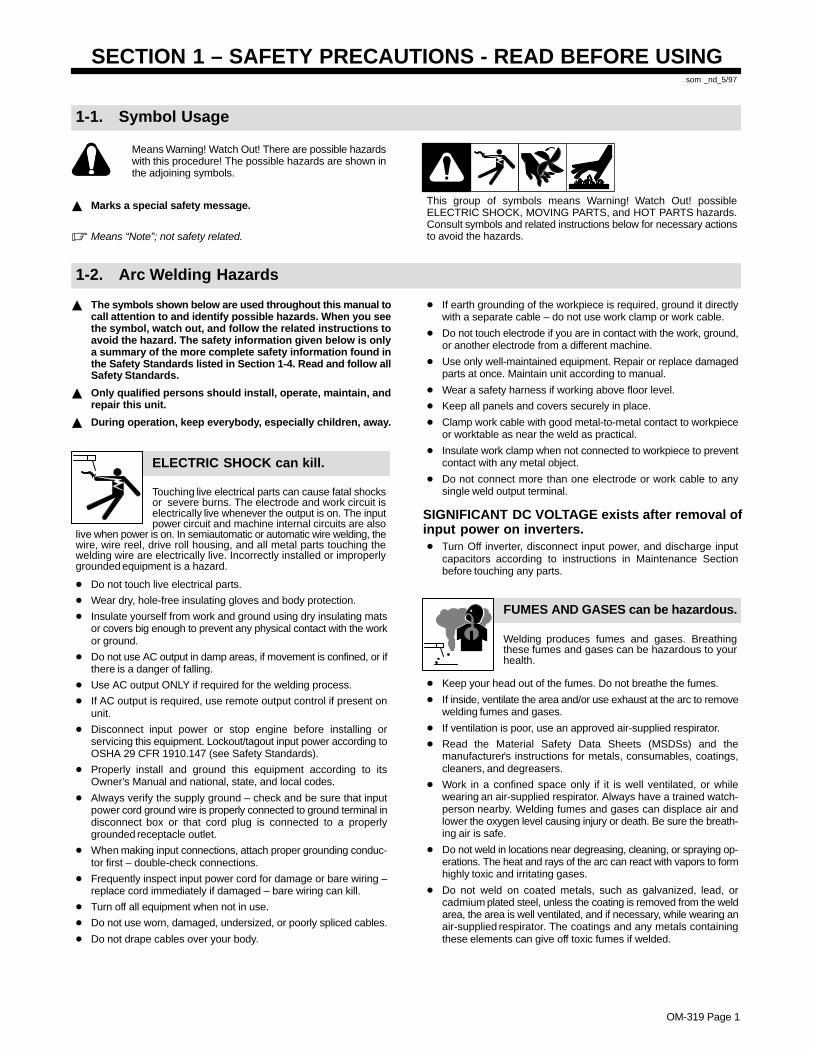
Means Warning! Watch Out! There are possible hazardswith this procedure! The possible hazards are shown inthe adjoining symbols.
� Marks a special safety message.
� Means “Note”; not safety related.
This group of symbols means Warning! Watch Out! possibleELECTRIC SHOCK, MOVING PARTS, and HOT PARTS hazards.Consult symbols and related instructions below for necessary actionsto avoid the hazards.
1-2. Arc Welding Hazards
� The symbols shown below are used throughout this manual tocall attention to and identify possible hazards. When you seethe symbol, watch out, and follow the related instructions toavoid the hazard. The safety information given below is onlya summary of the more complete safety information found inthe Safety Standards listed in Section 1-4. Read and follow allSafety Standards.
� Only qualified persons should install, operate, maintain, andrepair this unit.
� During operation, keep everybody, especially children, away.
ELECTRIC SHOCK can kill.
Touching live electrical parts can cause fatal shocksor severe burns. The electrode and work circuit iselectrically live whenever the output is on. The inputpower circuit and machine internal circuits are also
live when power is on. In semiautomatic or automatic wire welding, thewire, wire reel, drive roll housing, and all metal parts touching thewelding wire are electrically live. Incorrectly installed or improperlygrounded equipment is a hazard.
� Do not touch live electrical parts.
� Wear dry, hole-free insulating gloves and body protection.
� Insulate yourself from work and ground using dry insulating matsor covers big enough to prevent any physical contact with the workor ground.
� Do not use AC output in damp areas, if movement is confined, or ifthere is a danger of falling.
� Use AC output ONLY if required for the welding process.
� If AC output is required, use remote output control if present onunit.
� Disconnect input power or stop engine before installing orservicing this equipment. Lockout/tagout input power according toOSHA 29 CFR 1910.147 (see Safety Standards).
� Properly install and ground this equipment according to itsOwner’s Manual and national, state, and local codes.
� Always verify the supply ground – check and be sure that inputpower cord ground wire is properly connected to ground terminal indisconnect box or that cord plug is connected to a properlygrounded receptacle outlet.
� When making input connections, attach proper grounding conduc-tor first – double-check connections.
� Frequently inspect input power cord for damage or bare wiring –replace cord immediately if damaged – bare wiring can kill.
� Turn off all equipment when not in use.
� Do not use worn, damaged, undersized, or poorly spliced cables.
� Do not drape cables over your body.
� If earth grounding of the workpiece is required, ground it directlywith a separate cable – do not use work clamp or work cable.
� Do not touch electrode if you are in contact with the work, ground,or another electrode from a different machine.
� Use only well-maintained equipment. Repair or replace damagedparts at once. Maintain unit according to manual.
� Wear a safety harness if working above floor level.
� Keep all panels and covers securely in place.
� Clamp work cable with good metal-to-metal contact to workpieceor worktable as near the weld as practical.
� Insulate work clamp when not connected to workpiece to preventcontact with any metal object.
� Do not connect more than one electrode or work cable to anysingle weld output terminal.
SIGNIFICANT DC VOLTAGE exists after removal ofinput power on inverters.� Turn Off inverter, disconnect input power, and discharge input
capacitors according to instructions in Maintenance Sectionbefore touching any parts.
Welding produces fumes and gases. Breathingthese fumes and gases can be hazardous to yourhealth.
FUMES AND GASES can be hazardous.
� Keep your head out of the fumes. Do not breathe the fumes.
� If inside, ventilate the area and/or use exhaust at the arc to removewelding fumes and gases.
� If ventilation is poor, use an approved air-supplied respirator.
� Read the Material Safety Data Sheets (MSDSs) and themanufacturer’s instructions for metals, consumables, coatings,cleaners, and degreasers.
� Work in a confined space only if it is well ventilated, or whilewearing an air-supplied respirator. Always have a trained watch-person nearby. Welding fumes and gases can displace air andlower the oxygen level causing injury or death. Be sure the breath-ing air is safe.
� Do not weld in locations near degreasing, cleaning, or spraying op-erations. The heat and rays of the arc can react with vapors to formhighly toxic and irritating gases.
� Do not weld on coated metals, such as galvanized, lead, orcadmium plated steel, unless the coating is removed from the weldarea, the area is well ventilated, and if necessary, while wearing anair-supplied respirator. The coatings and any metals containingthese elements can give off toxic fumes if welded.
OM-319 Page 2
Arc rays from the welding process produce intensevisible and invisible (ultraviolet and infrared) raysthat can burn eyes and skin. Sparks fly off from theweld.
ARC RAYS can burn eyes and skin.
� Wear a welding helmet fitted with a proper shade of filter to protectyour face and eyes when welding or watching (see ANSI Z49.1and Z87.1 listed in Safety Standards).
� Wear approved safety glasses with side shields under yourhelmet.
� Use protective screens or barriers to protect others from flash andglare; warn others not to watch the arc.
� Wear protective clothing made from durable, flame-resistant mate-rial (leather and wool) and foot protection.
Welding on closed containers, such as tanks,drums, or pipes, can cause them to blow up. Sparkscan fly off from the welding arc. The flying sparks, hotworkpiece, and hot equipment can cause fires and
burns. Accidental contact of electrode to metal objects can causesparks, explosion, overheating, or fire. Check and be sure the area issafe before doing any welding.
WELDING can cause fire or explo-sion.
� Protect yourself and others from flying sparks and hot metal.
� Do not weld where flying sparks can strike flammable material.
� Remove all flammables within 35 ft (10.7 m) of the welding arc. Ifthis is not possible, tightly cover them with approved covers.
� Be alert that welding sparks and hot materials from welding caneasily go through small cracks and openings to adjacent areas.
� Watch for fire, and keep a fire extinguisher nearby.
� Be aware that welding on a ceiling, floor, bulkhead, or partition cancause fire on the hidden side.
� Do not weld on closed containers such as tanks, drums, or pipes,unless they are properly prepared according to AWS F4.1 (seeSafety Standards).
� Connect work cable to the work as close to the welding area aspractical to prevent welding current from traveling long, possiblyunknown paths and causing electric shock and fire hazards.
� Do not use welder to thaw frozen pipes.
� Remove stick electrode from holder or cut off welding wire atcontact tip when not in use.
� Wear oil-free protective garments such as leather gloves, heavyshirt, cuffless trousers, high shoes, and a cap.
� Remove any combustibles, such as a butane lighter or matches,from your person before doing any welding.
FLYING METAL can injure eyes.
� Welding, chipping, wire brushing, and grindingcause sparks and flying metal. As welds cool,they can throw off slag.
� Wear approved safety glasses with sideshields even under your welding helmet.
BUILDUP OF GAS can injure or kill.
� Shut off shielding gas supply when not in use.� Always ventilate confined spaces or use
approved air-supplied respirator.
HOT PARTS can cause severe burns.
� Do not touch hot parts bare handed.� Allow cooling period before working on gun or
torch.
MAGNETIC FIELDS can affect pacemak-ers.
� Pacemaker wearers keep away.� Wearers should consult their doctor before
going near arc welding, gouging, or spotwelding operations.
NOISE can damage hearing.
Noise from some processes or equipment candamage hearing.
� Wear approved ear protection if noise level ishigh.
Shielding gas cylinders contain gas under highpressure. If damaged, a cylinder can explode. Sincegas cylinders are normally part of the weldingprocess, be sure to treat them carefully.
CYLINDERS can explode if damaged.
� Protect compressed gas cylinders from excessive heat, mechani-cal shocks, slag, open flames, sparks, and arcs.
� Install cylinders in an upright position by securing to a stationarysupport or cylinder rack to prevent falling or tipping.
� Keep cylinders away from any welding or other electrical circuits.
� Never drape a welding torch over a gas cylinder.
� Never allow a welding electrode to touch any cylinder.
� Never weld on a pressurized cylinder – explosion will result.
� Use only correct shielding gas cylinders, regulators, hoses, and fit-tings designed for the specific application; maintain them andassociated parts in good condition.
� Turn face away from valve outlet when opening cylinder valve.
� Keep protective cap in place over valve except when cylinder is inuse or connected for use.
� Read and follow instructions on compressed gas cylinders,associated equipment, and CGA publication P-1 listed in SafetyStandards.

OM-319 Page 3
1-3. Additional Symbols For Installation, Operation, And Maintenance
FIRE OR EXPLOSION hazard.
� Do not install or place unit on, over, or nearcombustible surfaces.
� Do not install unit near flammables.
� Do not overload building wiring – be sure power supply system isproperly sized, rated, and protected to handle this unit.
FALLING UNIT can cause injury.
� Use lifting eye to lift unit only, NOT runninggear, gas cylinders, or any other accessories.
� Use equipment of adequate capacity to lift andsupport unit.
� If using lift forks to move unit, be sure forks arelong enough to extend beyond opposite side ofunit.
OVERUSE can cause OVERHEATING
� Allow cooling period; follow rated duty cycle.� Reduce current or reduce duty cycle before
starting to weld again.� Do not block or filter airflow to unit.
STATIC (ESD) can damage PC boards.
� Put on grounded wrist strap BEFORE handlingboards or parts.
� Use proper static-proof bags and boxes tostore, move, or ship PC boards.
MOVING PARTS can cause injury.
� Keep away from moving parts.� Keep away from pinch points such as drive
rolls.
WELDING WIRE can cause injury.
� Do not press gun trigger until instructed to doso.
� Do not point gun toward any part of the body,other people, or any metal when threadingwelding wire.
MOVING PARTS can cause injury.
� Keep away from moving parts such as fans.� Keep all doors, panels, covers, and guards
closed and securely in place.
H.F. RADIATION can cause interference.
� High-frequency (H.F.) can interfere with radionavigation, safety services, computers, andcommunications equipment.
� Have only qualified persons familiar withelectronic equipment perform this installation.
� The user is responsible for having a qualified electrician prompt-ly correct any interference problem resulting from the installa-tion.
� If notified by the FCC about interference, stop using theequipment at once.
� Have the installation regularly checked and maintained.
� Keep high-frequency source doors and panels tightly shut, keepspark gaps at correct setting, and use grounding and shielding tominimize the possibility of interference.
ARC WELDING can cause interference.
� Electromagnetic energy can interfere withsensitive electronic equipment such ascomputers and computer-driven equipmentsuch as robots.
� Be sure all equipment in the welding area iselectromagnetically compatible.
� To reduce possible interference, keep weld cables as short aspossible, close together, and down low, such as on the floor.
� Locate welding operation 100 meters from any sensitive elec-tronic equipment.
� Be sure this welding machine is installed and groundedaccording to this manual.
� If interference still occurs, the user must take extra measuressuch as moving the welding machine, using shielded cables,using line filters, or shielding the work area.
1-4. Principal Safety Standards
Safety in Welding and Cutting, ANSI Standard Z49.1, from AmericanWelding Society, 550 N.W. LeJeune Rd, Miami FL 33126Safety and Health Standards, OSHA 29 CFR 1910, from Superinten-dent of Documents, U.S. Government Printing Office, Washington, D.C.20402.Recommended Safe Practices for the Preparation for Welding and Cut-ting of Containers That Have Held Hazardous Substances, AmericanWelding Society Standard AWS F4.1, from American Welding Society,550 N.W. LeJeune Rd, Miami, FL 33126National Electrical Code, NFPA Standard 70, from National Fire Protec-tion Association, Batterymarch Park, Quincy, MA 02269.
Safe Handling of Compressed Gases in Cylinders, CGA Pamphlet P-1,from Compressed Gas Association, 1235 Jefferson Davis Highway,Suite 501, Arlington, VA 22202.Code for Safety in Welding and Cutting, CSA Standard W117.2, fromCanadian Standards Association, Standards Sales, 178 RexdaleBoulevard, Rexdale, Ontario, Canada M9W 1R3.Safe Practices For Occupation And Educational Eye And FaceProtection, ANSI Standard Z87.1, from American National StandardsInstitute, 1430 Broadway, New York, NY 10018.Cutting And Welding Processes, NFPA Standard 51B, from NationalFire Protection Association, Batterymarch Park, Quincy, MA 02269.

OM-319 Page 4
1-5. EMF Information
Considerations About Welding And The Effects Of Low FrequencyElectric And Magnetic FieldsWelding current, as it flows through welding cables, will cause electro-magnetic fields. There has been and still is some concern about suchfields. However, after examining more than 500 studies spanning 17years of research, a special blue ribbon committee of the NationalResearch Council concluded that: “The body of evidence, in thecommittee’s judgment, has not demonstrated that exposure to power-frequency electric and magnetic fields is a human-health hazard.”However, studies are still going forth and evidence continues to beexamined. Until the final conclusions of the research are reached, youmay wish to minimize your exposure to electromagnetic fields whenwelding or cutting.To reduce magnetic fields in the workplace, use the followingprocedures:
1. Keep cables close together by twisting or taping them.
2. Arrange cables to one side and away from the operator.
3. Do not coil or drape cables around your body.
4. Keep welding power source and cables as far away from opera-tor as practical.
5. Connect work clamp to workpiece as close to the weld as possi-ble.
About Pacemakers:Pacemaker wearers consult your doctor first. If cleared by your doctor,then following the above procedures is recommended.

OM-319 Page 5
SECTION 1 – CONSIGNES DE SECURITE – LIRE AVANTUTILISATION
som _nd_fre 5/97
1-1. Signification des symboles
Signifie Mise en garde ! Soyez vigilant ! Cette procédureprésente des risques de danger ! Ceux-ci sont identifiéspar des symboles adjacents aux directives.
� Identifie un message de sécurité particulier.
� Signifie NOTA ; n’est pas relatif à la sécurité.
Ce groupe de symboles signifie Mise en garde ! Soyez vigilant ! Il y a desrisques de danger reliés aux CHOCS ÉLECTRIQUES, aux PIÈCES ENMOUVEMENT et aux PIÈCES CHAUDES. Reportez-vous aux symboleset aux directives ci-dessous afin de connaître les mesures à prendre pouréviter tout danger.
1-2. Dangers relatifs au soudage à l’arc
� Les symboles présentés ci-après sont utilisés tout au long duprésent manuel pour attirer votre attention et identifier les risquesde danger. Lorsque vous voyez un symbole, soyez vigilant etsuivez les directives mentionnées afin d’éviter tout danger. Lesconsignes de sécurité présentées ci-après ne font que résumerl’information contenue dans les normes de sécurité énuméréesà la section 1-4. Veuillez lire et respecter toutes ces normes desécurité.
� L’installation, l’utilisation, l’entretien et les réparations ne doi-vent être confiés qu’à des personnes qualifiées.
� Au cours de l’utilisation, tenir toute personne à l’écart et plus par-ticulièrement les enfants.
UN CHOC ÉLECTRIQUE peut tuer.
Un simple contact avec des pièces électriques peutprovoquer une électrocution ou des blessures graves.L’électrode et le circuit de soudage sont sous tensiondès que l’appareil est sur ON. Le circuit d’entrée et lescircuits internes de l’appareil sont également sous
tension à ce moment-là. En soudage semi-automatique ou automatique,le fil, le dévidoir, le logement des galets d’entraînement et les piècesmétalliques en contact avec le fil de soudage sont sous tension. Desmatériels mal installés ou mal mis à la terre présentent un danger.
� Ne jamais toucher les pièces électriques sous tension.� Porter des gants et des vêtements de protection secs ne comportant
pas de trous.� S’isoler de la pièce et de la terre au moyen de tapis ou d’autres
moyens isolants suffisamment grands pour empêcher le contact phy-sique éventuel avec la pièce ou la terre.
� Ne pas se servir de source électrique àcourant électrique dans les zoneshumides, dans les endroits confinés ou là où on risque de tomber.
� Se servir d’une source électrique àcourant électrique UNIQUEMENT si leprocédé de soudage le demande.
� Si l’utilisation d’une source électrique àcourant électrique s’avère néces-saire, se servir de la fonction de télécommande si l’appareil en est équipé.
� Couper l’alimentation ou arrêter le moteur avant de procéder à l’instal-lation, à la réparation ou à l’entretien de l’appareil. Déverrouillerl’alimentation selon la norme OSHA 29 CFR 1910.147 (voir normes desécurité).
� Installer et mettre à la terre correctement cet appareil conformément àson manuel d’utilisation et aux codes nationaux, provinciaux etmunicipaux.
� Toujours vérifier la terre du cordon d’alimentation – Vérifier et s’assu-rer que le fil de terre du cordon d’alimentation est bien raccordé à laborne de terre du sectionneur ou que la fiche du cordon est raccordéeà une prise correctement mise à la terre.
� En effectuant les raccordements d’entrée fixer d’abord le conducteurde mise à la terre approprié et contre-vérifier les connexions.
� Vérifier fréquemment le cordon d’alimentation pour voir s’il n’est pasendommagé ou dénudé – remplacer le cordon immédiatement s’il estendommagé – un câble dénudé peut provoquer une électrocution.
� Mettre l’appareil hors tension quand on ne l’utilise pas.� Ne pas utiliser des câbles usés, endommagés, de grosseur insuffi-
sante ou mal épissés.� Ne pas enrouler les câbles autour du corps.� Si la pièce soudée doit être mise à la terre, le faire directement avec un
câble distinct – ne pas utiliser le connecteur de pièce ou le câble deretour.
� Ne pas toucher l’électrode quand on est en contact avec la pièce, laterre ou une électrode provenant d’une autre machine.
� N’utiliser qu’un matériel en bon état. Réparer ou remplacer sur-le-champ les pièces endommagées. Entretenir l’appareil conformémentà ce manuel.
� Porter un harnais de sécurité quand on travaille en hauteur.
� Maintenir solidement en place tous les panneaux et capots.
� Fixer le câble de retour de façon à obtenir un bon contact métal-métalavec la pièce à souder ou la table de travail, le plus près possible de lasoudure.
� Isoler la pince de masse quand pas mis à la pièce pour éviter le contactavec tout objet métallique.
Il y a DU COURANT CONTINU IMPORTANT dans lesconvertisseurs après la suppression de l’alimenta-tion électrique.� Arrêter les convertisseurs, débrancher le courant électrique, et dé-
charger les condensateurs d’alimentation selon les instructionsindiquées dans la partie entretien avant de toucher les pièces.
Le soudage génère des fumées et des gaz. Leurinhalation peut être dangereux pour votre santé.
� Eloigner votre tête des fumées. Ne pas respirerles fumées.
� A l’intérieur, ventiler la zone et/ou utiliser un échappement au niveaude l’arc pour l’évacuation des fumées et des gaz de soudage.
� Si la ventilation est insuffisante, utiliser un respirateur à alimenta-tion d’air homologué.
� Lire les spécifications de sécurité des matériaux (MSDSs) et lesinstructions du fabricant concernant les métaux, les consomma-bles, les revêtements, les nettoyants et les dégraisseurs.
� Travailler dans un espace fermé seulement s’il est bien ventilé ou enportant un respirateur à alimentation d’air. Demander toujours à unsurveillant dûment formé de se tenir à proximité. Des fumées et desgaz de soudage peuvent déplacer l’air et abaisser le niveau d’oxy-gène provoquant des blessures ou des accidents mortels. S’assu-rer que l’air de respiration ne présente aucun danger.
� Ne pas souder dans des endroits situés à proximité d’opérations dedégraissage, de nettoyage ou de pulvérisation. La chaleur et lesrayons de l’arc peuvent réagir en présence de vapeurs et former desgaz hautement toxiques et irritants.
� Ne pas souder des métaux munis d’un revêtement, tels que l’aciergalvanisé, plaqué en plomb ou au cadmium à moins que le revête-ment n’ait été enlevé dans la zone de soudure, que l’endroit soit bienventilé, et si nécessaire, en portant un respirateur à alimentationd’air. Les revêtements et tous les métaux renfermant ces élémentspeuvent dégager des fumées toxiques en cas de soudage.
LES FUMÉES ET LES GAZ peuventêtre dangereux.

OM-319 Page 6
Le rayonnement de l’arc du procédé de soudagegénère des rayons visibles et invisibles intenses(ultraviolets et infrarouges) susceptibles de provoquer
des brûlures dans les yeux et sur la peau. Des étincelles sont projetéespendant le soudage.
LES RAYONS DE L’ARC peuvent pro-voquer des brûlures dans les yeux etsur la peau.
� Porter un casque de soudage muni d’un écran de filtre approprié pourprotéger votre visage et vos yeux pendant le soudage ou pour regar-der (voir ANSI Z49.1 et Z87.1 énuméré dans les normes de sécurité).
� Porter des protections approuvés pour les oreilles si le niveau sondre esttrop élevé.
� Utiliser des écrans ou des barrières pour protéger des tiers de l’éclairet de l’éblouissement; demander aux autres personnes de ne pas re-garder l’arc.
� Porter des vêtements de protection constitué dans une matière dura-ble, résistant au feu (cuir ou laine) et une protection des pieds.
Le soudage effectué sur des conteneurs fermés telsque des réservoirs, tambours ou des conduites peutprovoquer leur éclatement. Des étincelles peuvent êtreprojetées de l’arc de soudure. La projection d’étincel-
les, des pièces chaudes et des équipements chauds peut provoquer desincendies et des brûlures. Le contact accidentel de l’électrode avec desobjets métalliques peut provoquer des étincelles, une explosion, unsurchauffement ou un incendie. Avant de commencer le soudage, vérifieret s’assurer que l’endroit ne présente pas de danger.
LE SOUDAGE peut provoquer unincendie ou une explosion.
� Se protéger et d’autres personnes de la projection d’étincelles et demétal chaud.
� Ne pas souder dans un endroit là où des étincelles peuvent tomber surdes substances inflammables.
� Déplacer toutes les substances inflammables à une distance de 10,7m de l’arc de soudage. En cas d’impossibilité les recouvrir soigneuse-ment avec des protections homologués.
� Des étincelles et des matériaux chauds du soudage peuvent facile-ment passer dans d’autres zones en traversant de petites fissures etdes ouvertures.
� Surveiller tout déclenchement d’incendie et tenir un extincteur à proxi-mité.
� Le soudage effectué sur un plafond, plancher, paroi ou séparationpeut déclencher un incendie de l’autre côté.
� Ne pas effectuer le soudage sur des conteneurs fermés tels que desréservoirs, tambours, ou conduites, à moins qu’ils n’aient été prépa-rés correctement conformément à AWS F4.1 (voir les normes desécurité).
� Brancher le câble sur la pièce le plus près possible de la zone de sou-dage pour éviter le transport du courant sur une longue distance pardes chemins inconnus éventuels en provoquant des risques d’élec-trocution et d’incendie.
� Ne pas utiliser le poste de soudage pour dégeler des conduites ge-lées.
� En cas de non utilisation, enlever la baguette d’électrode du porte-électrode ou couper le fil à la pointe de contact.
� Porter des vêtements de protection dépourvus d’huile tels que desgants en cuir, une chemise en matériau lourd, des pantalons sans re-vers, des chaussures hautes et un couvre chef.
� Avant de souder, retirer toute substance combustible de vos pochestelles qu’un allumeur au butane ou des allumettes.
DES PARTICULES VOLANTESpeuvent blesser les yeux.
� Le soudage, l’écaillement, le passage de la pièceà la brosse en fil de fer, et le meulage génèrentdes étincelles et des particules métalliques vo-
lantes. Pendant la période de refroidissement des soudures, elles ris-quent de projeter du laitier.� Porter des lunettes de sécurité avec écrans latéraux ou un écran facial.
LES ACCUMULATIONS DE GAZ ris-quent de provoquer des blessures oumême la mort.
� Fermer l’alimentation du gaz protecteur en cas denon utilisation.
� Veiller toujours à bien aérer les espaces confinés ou se servir d’un respi-rateur d’adduction d’air homologué.
DES PIÈCES CHAUDES peuvent pro-voquer des brûlures graves.
� Ne pas toucher des parties chaudes à mains nues� Prévoir une période de refroidissement avant
d’utiliser le pistolet ou la torche.
LES CHAMPS MAGNÉTIQUES peuventaffecter les stimulateurs cardiaques.
� Porteurs de stimulateur cardiaque, restez à distance.� Les porteurs d’un stimulateur cardiaque doivent
d’abord consulter leur médecin avant de s’approcherdes opérations de soudage à l’arc, de gougeage oude soudage par points.
LE BRUIT peut affecter l’ouïe.
Le bruit des processus et des équipements peut affecterl’ouïe.
� Porter des protections approuvés pour les oreilles sile niveau sondre est trop élevé.
Des bouteilles de gaz protecteur contiennent du gazsous haute pression. Si une bouteille est endomma-gée, elle peut exploser. Du fait que les bouteilles de gazfont normalement partie du procédé de soudage, les
manipuler avec précaution.
� Protéger les bouteilles de gaz comprimé d’une chaleur excessive,des chocs mécaniques, du laitier, des flammes ouvertes, des étin-celles et des arcs.
� Placer les bouteilles debout en les fixant dans un support stationnai-re ou dans un porte-bouteilles pour les empêcher de tomber ou dese renverser.
� Tenir les bouteilles éloignées des circuits de soudage ou autres cir-cuits électriques.
� Ne jamais placer une torche de soudage sur une bouteille à gaz.� Une électrode de soudage ne doit jamais entrer en contact avec une
bouteille.� Ne jamais souder une bouteille pressurisée – risque d’explosion.� Utiliser seulement des bouteilles de gaz protecteur, régulateurs,
tuyaux et raccords convenables pour cette application spécifique;les maintenir ainsi que les éléments associés en bon état.
� Ne pas tenir la tête en face de la sortie en ouvrant la soupape de labouteille.
� Maintenir le chapeau de protection sur la soupape, sauf en cas d’uti-lisation ou de branchement de la bouteille.
� Lire et suivre les instructions concernant les bouteilles de gaz com-primé, les équipements associés et les publications P-1 CGA énu-mérées dans les normes de sécurité.
Si des BOUTEILLES sont endomma-gées, elles pourront exploser.

OM-319 Page 7
1-3. Dangers supplémentaires en relation avec l’installation, le fonctionnementet la maintenance
Risque D’INCENDIE OUD’EXPLOSION.
� Ne pas placer l’appareil sur, au-dessus ou à proxi-mité de surfaces infllammables.
� Ne pas installer l’appareil à proximité de produits inflammables� Ne pas surcharger l’installation électrique – s”assurer que l’alimen-
tation est correctement dimensionné et protégé avant de mettrel’appareil en service.
LA CHUTE DE L’APPAREIL peutblesser.
� Utiliser l’anneau de levage uniquement pour sou-lever l’appareil, NON PAS les chariot, les bouteil-les de gaz ou tout autre accessoire.
� Utiliser un engin d’une capacité appropriée poursoulever l’appareil.
� En utilisant des fourches de levage pour déplacer l’unité, s’assurerque les fourches sont suffisamment longues pour dépasser du côtéopposé de l’appareil.
L’EMPLOI EXCESSIF peutSURCHAUFFER L’ÉQUIPEMENT.
� Prévoir une période de refroidissement, respec-ter le cycle opératoire nominal.
� Réduire le courant ou le cycle opératoire avant derecommancer le soudage.
� Ne pas obstruer les passages d’air du poste.
LES CHARGES ÉLECTROSTATI-QUES peuvent endommager les cir-cuits imprimés.
� Établir la connexion avec la barrette de terreavant de manipuler des cartes ou des pièces.
� Utiliser des pochettes et des boîtes antistatiquespour stocker, déplacer ou expédier des cartes decircuits imprimes.
DES ORGANES MOBILES peuventprovoquer des blessures.
� Ne pas s’approcher des organes mobiles.� Ne pas s’approcher des points de coincement
tels que des rouleaux de commande.
LES FILS DE SOUDAGE peuvent pro-voquer des blessures.
� Ne pas appuyer sur la gachette avant d’en avoirreçu l’instruction.
� Ne pas diriger le pistolet vers soi, d’autres person-nes ou toute pièce mécanique en engageant le filde soudage.
DES ORGANES MOBILES peuventprovoquer des blessures.
� Rester à l’écart des organes mobiles comme leventilateur.
� Maintenir fermés et fixement en place les portes,panneaux, recouvrements et dispositifs deprotection.
LE RAYONNEMENT HAUTE FRÉ-QUENCE (H.F.) risque de provoquerdes interférences.
� Le rayonnement haute frequence peut provoquerdes interférences avec les équipements de ra-dio–navigation et de communication, les servicesde sécurité et les ordinateurs.
� Demander seulement à des personnes qualifiées familiariséesavec des équipements électroniques de faire fonctionner l’installa-tion.
� L’utilisateur est tenu de faire corriger rapidement par un électricienqualifié les interférences résultant de l’installation.
� Si le FCC signale des interférences, arrêter immédiatement l’appa-reil.
� Effectuer régulièrement le contrôle et l’entretien de l’installation.� Maintenir soigneusement fermés les portes et les panneaux des
sources de haute fréquence, maintenir les éclateurs à une distancecorrecte et utiliser une terre et et un blindage pour réduire les interfé-rences éventuelles.
LE SOUDAGE À L’ARC risque deprovoquer des interférences.
� L’énergie électromagnétique risque de provoquerdes interférences pour l’équipement électroniquesensible tel que les ordinateurs et l’équipementcommandé par ordinateur tel que les robots.
� Veiller à ce que tout l’équipement de la zone de soudage soit com-patible électromagnétiquement.
� Pour réduire la possibilité d’interférence, maintenir les câbles desoudage aussi courts que possible, les grouper, et les poser aussibas que possible (ex. par terre).
� Veiller à souder à une distance de 100 mètres de tout équipementélectronique sensible.
� Veiller à ce que ce poste de soudage soit posé et mis à la terreconformément à ce mode d’emploi.
� En cas d’interférences après avoir pris les mesures précédentes, ilincombe à l’utilisateur de prendre des mesures supplémentaires tel-les que le déplacement du poste, l’utilisation de câbles blindés, l’uti-lisation de filtres de ligne ou la pose de protecteurs dans la zone detravail.
LES CHAMPS MAGNÉTIQUES peuventaffecter les stimulateurs cardiaques.
� Porteurs de stimulateur cardiaque, restez à dis-tance.
� Les porteurs d’un stimulateur cardiaque doiventd’abord consulter leur médecin avant de s’appro-cher des opérations de soudage à l’arc, de gou-geage ou de soudage par points.

OM-319 Page 8
1-4. Principales normes de sécurité
Safety in Welding and Cutting, norme ANSI Z49.1, de l’American Wel-ding Society, 550 N.W. Lejeune Rd, Miami FL 33126
Safety and Health Sandards, OSHA 29 CFR 1910, du Superintendentof Documents, U.S. Government Printing Office, Washington, D.C.20402.
Recommended Safe Practice for the Preparation for Welding and Cut-ting of Containers That Have Held Hazardous Substances, norme AWSF4.1, de l’American Welding Society, 550 N.W. Lejeune Rd, Miami FL33126
National Electrical Code, NFPA Standard 70, de la National Fire Protec-tion Association, Batterymarch Park, Quincy, MA 02269.
Safe Handling of Compressed Gases in Cylinders, CGA Pamphlet P-1,de la Compressed Gas Association, 1235 Jefferson Davis Highway,Suite 501, Arlington, VA 22202.
Règles de sécurité en soudage, coupage et procédés connexes, normeCSA W117.2, de l’Association canadienne de normalisation, vente denormes, 178 Rexdale Boulevard, Rexdale (Ontario) Canada M9W 1R3.
Safe Practices For Occupation And Educational Eye And Face Protec-tion, norme ANSI Z87.1, de l’American National Standards Institute,1430 Broadway, New York, NY 10018.
Cutting and Welding Processes, norme NFPA 51B, de la National FireProtection Association, Batterymarch Park, Quincy, MA 02269.
1-5. Information sur les champs électromagnétiques
Données sur le soudage électrique et sur les effets, pour l’organisme,des champs magnétiques basse fréquence
Le courant de soudage, pendant son passage dans les câbles de sou-dage, causera des champs électromagnétiques. Il y a eu et il y a encoreun certain souci à propos de tels champs. Cependant, après avoir ex-aminé plus de 500 études qui ont été faites pendant une période derecherche de 17 ans, un comité spécial ruban bleu du National Re-search Council a conclu: “L’accumulation de preuves, suivant lejugement du comité, n’a pas démontré que l’exposition aux champsmagnétiques et champs électriques à haute fréquence représente unrisque à la santé humaine”. Toutefois, des études sont toujours en courset les preuves continuent à être examinées. En attendant que les con-clusions finales de la recherche soient établies, il vous seraitsouhaitable de réduire votre exposition aux champs électromagnéti-ques pendant le soudage ou le coupage.
Afin de réduire les champs électromagnétiques dans l’environnementde travail, respecter les consignes suivantes :
1 Garder les câbles ensembles en les torsadant ou en lesattachant avec du ruban adhésif.
2 Mettre tous les câbles du côté opposé de l’opérateur.
3 Ne pas courber pas et ne pas entourer pas les câbles autour devotre corps.
4 Garder le poste de soudage et les câbles le plus loin possible devous.
5 Relier la pince de masse le plus près possible de la zone desoudure.
Consignes relatives aux stimulateurs cardiaques :
Les personnes qui portent un stimulateur cardiaque doivent avant toutconsulter leur docteur. Si vous êtes déclaré apte par votre docteur, il estalors recommandé de respecter les consignes ci–dessus.
OM-319 Page 9
SECTION 2 – INSTALLATION
2-1. Specifications
Amperes Input at AC Balanced RatedLoad Output; 60 Hz,
Single-Phase/Three-PhaseRated
Welding Output 200 V 230 V 460 V 575 V KVA KWAmperage
RangeMaxOCV
Three-Phase: NEMAClass I (60) – 300Amperes, 32 Volts
AC/DC, 60% Duty Cycle
42 37 18 15 14.8 14
Single-Phase: NEMAClass I (60) – 200Amperes, 28 Volts
AC/DC, 60% Duty Cycle
51 44 22 18 10.2 9
1–375 A 90
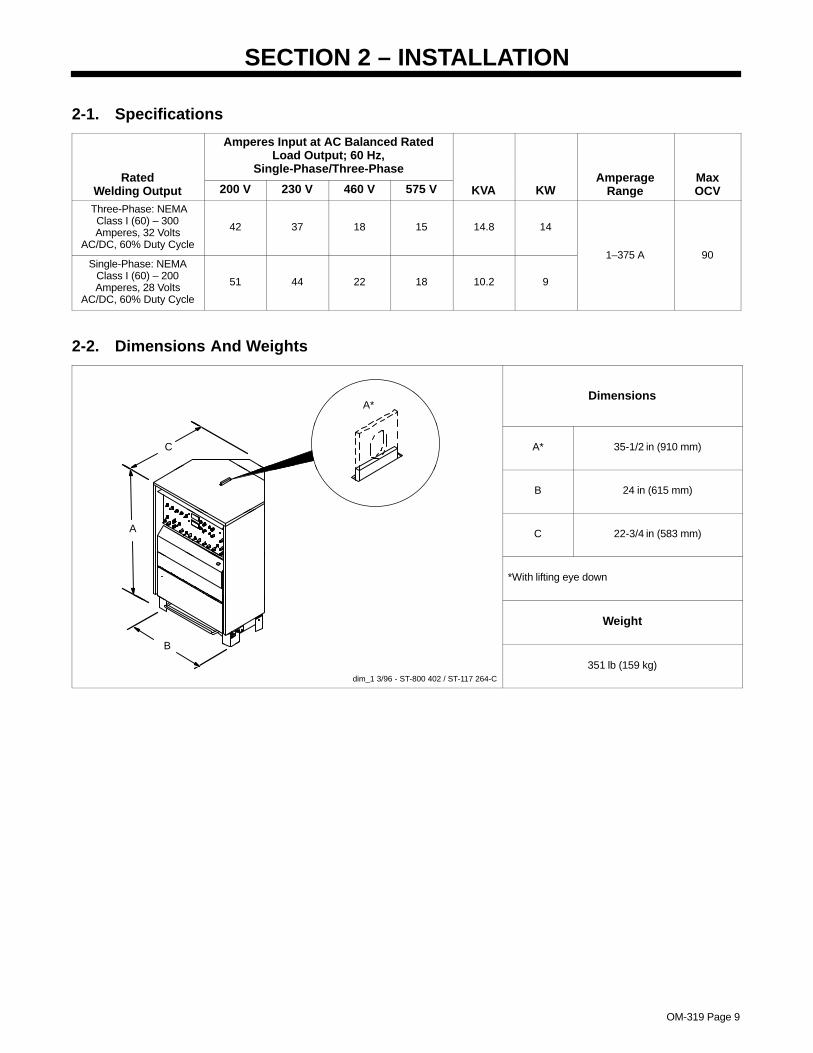
2-2. Dimensions And Weights
A*Dimensions
C A* 35-1/2 in (910 mm)
B 24 in (615 mm)
A C 22-3/4 in (583 mm)
*With lifting eye down
Weight
B
dim_1 3/96 - ST-800 402 / ST-117 264-C
351 lb (159 kg)

OM-319 Page 10
6 Minutes Welding 4 Minutes Resting
2-3. Duty Cycle And Overheating
Duty Cycle is percentage of 10 min-utes that unit can weld at rated loadwithout overheating.
If unit overheats, thermostat(s)opens, output stops, and coolingfan runs. Wait fifteen minutes forunit to cool. Reduce amperage orvoltage, or duty cycle beforewelding.
� Exceeding duty cycle candamage unit and void war-ranty.
60% Duty Cycle:At 200 Amperes With Single-Phase Input PowerAt 300 Amperes With Three-Phase Input Power
Overheating
0
15
A or V
ORReduce Duty CycleMinutes
sduty1 5/95 / ST-136 510-B
B. AC Mode
ssb1.1 10/91 – ST-168 007 / ST-168 006
The volt-ampere curves show theminimum and maximum voltageand amperage output capabilities ofthe welding power source. Curvesof other settings fall between thecurves shown.
A. DC Mode
2-4. Volt-Ampere Curves

OM-319 Page 11
2-5. Selecting A Location
1 Rating Label
Use rating label to determine inputpower needs.
2 Line Disconnect Device
Locate unit near correct inputpower supply.
� Special installation may berequired where gasoline orvolatile liquids are present –see NEC Article 511 or CECSection 20.
Movement
� Do not move or operate unitwhere it could tip.
Tipping
loc_1 3/96 Ref. ST-800 311-B
1
Location And Airflow
18 in
2
(460 mm)
18 in(460 mm)

OM-319 Page 12
2-6. 115 VAC Receptacle, Circuit Breaker, And Shielding Gas Connections
Ref. ST-800 312-A / Ref. ST-158 697-A
1 115 V 15 A AC ReceptacleRC2
2 Circuit Breaker CB1
Receptacle is protected from over-load by CB1.
Press button to reset breaker.
3 Gas Fittings
Fittings have 5/8-18 right-handthreads.
4 Cylinder Valve
Open valve slightly so gas flowblows dirt from valve. Close valve.
5 Regulator/Flowmeter
6 Flow Adjust
Typical flow rate is 15 cfh (cubic feetper hour).
2
1
3
Route Cables andhoses under bar.
5 46
5/8, 1-1/8 in
2-7. Weld Output Terminals And Selecting Cable Sizes
� ARC WELDING can cause Electromagnetic Interference.
To reduce possible interference, keep weld cables as short as possible, close together, and down low, such as on the floor.Locate welding operation 100 meters from any sensitive electronic equipment. Be sure this welding machine is installedand grounded according to this manual. If interference still occurs, the user must take extra measures such as movingthe welding machine, using shielded cables, using line filters, or shielding the work area.
Total Cable (Copper) Length In Weld Circuit Not Exceeding
100 ft (30 m) Or Less 150 ft(45 m)
200 ft(60 m)
250 ft(70 m)
300 ft(90 m)
350 ft(105 m)
400 ft(120 m)
Weld OutputTerminals
WeldingAmperes
10 – 60%DutyCycle
60 – 100%DutyCycle
10 – 100% Duty Cycle
100 4 4 4 3 2 1 1/0 1/0
150 3 3 2 1 1/0 2/0 3/0 3/0
200 3 2 1 1/0 2/0 3/0 4/0 4/0
250 2 1 1/0 2/0 3/0 4/0 2-2/0 2-2/0
300 1 1/0 2/0 3/0 4/0 2-2/0 2-3/0 2-3/0
350 1/0 2/0 3/0 4/0 2-2/0 2-3/0 2-3/0 2-4/0
400 1/0 2/0 3/0 4/0 2-2/0 2-3/0 2-4/0 2-4/0
Ref. ST-800 312-A500 2/0 3/0 4/0 2-2/0 2-3/0 2-4/0 3-3/0 3-3/0
*Weld cable size (AWG) is based on either a 4 volts or less drop or a current density of at least 300 circular mils per ampere. Contact yourdistributor for the mm2 equivalent weld cable sizes. S-0007-E

OM-319 Page 13
2-8. Remote 14 Receptacle Information
Socket* Information
A 24 volts ac.
B Contact closure to A completes 24 voltsac contactor control circuit.
C Command reference; 0 to +10 volts dcoutput to remote control.
D Remote control circuit common.
A JB K I
L N H
A AMPERAGEE 0 to +10 volts dc input command signal
from remote control.
C L N HD M G
E FRef. ST-800 312-A
K Circuit Common.
*The remaining sockets are not used.
2-9. Electrical Service Guide
Single-Phase Three-Phase
Input Voltage 200 230 460 575 200 230 460 575
Input Amperes At Rated Output 51 44 22 18 42 37 18 15
Max Recommended Standard Fuse Or CircuitBreaker Rating In Amperes
80 70 35 25 60 60 30 20
Min Input Conductor Size In AWG/Kcmil 8 8 12 14 8 10 14 14
Max Recommended Input Conductor LengthIn Feet (Meters)
82(25)
108(33)
173(53)
176(54)
93(28)
80(24)
126(38)
196(60)
Min Grounding Conductor Size In AWG/Kcmil 8 8 12 14 10 10 14 14
Reference: 1996 National Electrical Code (NEC). S-0092J

OM-319 Page 14
2-10. Placing Jumper Links
Ref. ST-800 314
Check input voltage available atsite.
1 Jumper Link Label
Move jumper links to match inputvoltage, and label on unit.
Proceed to Section 2-11.
2 Primary Terminal Board
230 VOLTS
S-164 976
L1 L2 L3
460 VOLTS
L1 L2 L3
575 VOLTS
L1 L2 L3
1
2
200 VOLTS
S-072 135-B
L1 L2 L3
230 VOLTS
L1 L2 L3
460 VOLTS
L1 L2 L3
Do not overtighten.
3/8 in

OM-319 Page 15
2-11. Connecting Input Power
input_3 3/96 - Ref. ST-800 314
1 Input Power Connection Label
2 Input And GroundingConductors
See Section 2-9.
3 Line Disconnect Device
See Section 2-9.
Reinstall rear cover.
L1
L2
L3
L1
L2
L3
Single-Phase
S-155 124
Three-PhaseInput
IMPORTANTInput Power Connections
1 3
Green OrGreen With
Yellow Stripe(s)
TerminalBoard
GND/PE
GND/PE
Always Connect InputGrounding Conductor To
GROUND Stud On Frame First.
3
1
1
L2 2
3
L2
3/8, 1/2, 7/16 in
� Always connectgrounding conductor first.
= GND/PE
� Always connectgrounding conductor first.
= GND/PE
2
L3
L1
L1
Three-Phase Connections
Single-Phase Connections

OM-319 Page 16
2-12. Connecting To Automation Connector Receptacle RC12
Ref. ST-801 509 / ST-801 719
1 Main Control Board PC1
2 Automation ConnectorReceptacle RC12
3 Terminals 1–6
See chart for terminal functions.
4 Terminal Screws
Loosen terminal screws, insertwires into terminals, tightenscrews.
Tools Needed:
1
2
Electronic Box With UpperFront Panel Open
6
54
3
2
13
4
Terminal Function
6
5
Electrode negative amplitude (0–10 volts)
Ground (circuit common)
4 Electrode Positive amplitude (0–10 volts)
3 Pulse train (0 or 15 volts, controls frequency and balance)
2
1
Gas valve (0 off – +15 volts on)
Output contactor (0 off – +15 volts on)

OM-319 Page 17
SECTION 3 – OPERATION
3-1. Controls
ST-800 312-A
1 2 3 4 5 6 7 8 9 1110
12
1 Mode Switch(See Section 3-3)
2 Amperage Switch(See Section 3-6)
3 Output Switch And Light(See Section 3-5)
4 Start Switch(See Section 3-11)
5 Polarity Switch And Lights(See Section 3-2)
6 Amperage/Preset Meter(See Section 3-4)
7 Voltmeter(See Section 3-4)
8 Amperage AdjustmentControls (See Section 3-6)
9 AC Frequency Controls(See Section 3-9)
10 High Temperature ShutdownLight
11 Over Voltage Shutdown LightSee Section 4-2)
12 Postflow Time Control(See Section 3-10)
13 AC Balance Controls(See Section 3-8)
14 Power On/Off Switch(See Section 3-12)
� Wear approved ear muffs orear plugs if noise exposureexceeds OSHA limits.
13
14
3-2. Polarity Switch And Pilot Lights
Ref. ST-151 180-B
� Do not use AC output indamp areas, if movement isconfined, or if there is a dan-ger of falling. Use AC outputONLY if required for thewelding process, and thenuse a remote output control.
1 Polarity Switch
Use switch to select weld output.
2 Electrode Positive Pilot Light
3 Electrode Negative Pilot Light
Both lights go on when switch is inAC position.
1
2
3

OM-319 Page 18
3-3. Mode Switch
1 Mode Switch
Use switch to select SMAW oreither GTAW welding process.
Selecting either GTAW positionenables the Start switch and gasvalve; both are disabled when theSMAW position is selected.
GTAW Trigger Hold functions asfollows:
Press torch switch to start arc.Switch can be released and arc re-mains on. Press switch to stop arc.
1
3-4. Amperage/Preset Meter And Voltmeter
1 Amperage/Preset Meter
Use meter to preset amperage, acfrequency, and ac balance. Meterdisplays average weld amperageoutput of unit to nearest amperewhen welding.
2 Voltmeter
Voltmeter displays average voltage(to the nearest 0.1 V) at the weldoutput terminals.
1
2
3-5. Output Switch And Pilot Light
� Weld output terminals areenergized when switch is Onand power is On. Do nottouch torch or electrode andwork clamp at the same time.
1 Output Switch2 Pilot Light
Use switch to select way of control-ling unit output.
For weld output, place switch in Onposition.
For remote output control, placeswitch in Remote 14 position (seeSection 2-8).
Pilot light stays on continuously inOn position, but only when contac-tor is energized in Remote 14position.
1
2

OM-319 Page 19
3-6. Amperage Adjustment Controls
Ref. ST-151 180-B / Ref. S-0865
1 Amperage Control Switch
Use switch to select way of control-ling amperage adjustment.
For front panel control, place switchin Panel position.
For remote control, place switch inRemote 14 position.
2 Electrode Positive AmperageAdjustment Control AndPushbutton
Set Polarity switch to AC, presspushbutton and use control andAmperage/Preset meter to adjustweld amperage for positive half ofac square wave.
When Polarity switch is in ElectrodePositive position, pushbutton doesnot need to be pressed to adjustcontrol.
3 Electrode Negative AmperageAdjustment Control AndPushbutton
Set Polarity switch to AC, presspushbutton and use control andAmperage/Preset meter to adjustweld amperage for negative half ofac square wave.
When Polarity switch is in ElectrodeNegative position, pushbutton doesnot need to be pressed to adjustcontrol.
The controls require 3 turns to gofrom minimum to maximum, andmay be adjusted while welding.
Set Electrode Negative Amperage Level
3
Example: Setting Amperage For AC Output:
AMPERAGE/PRESET
Set Electrode Positive Amperage Level
2
AMPERAGE/PRESET
Output =
+150 A Electrode Positve
1
–250 A Electrode Negative
If Polarity switch is set incorrectly, the Amper-age/Preset meter goes blank when the push-button is pressed.
OM-319 Page 20
3-7. Examples Of Combination Remote Amperage Control
Ref. ST-151 180-B / S-0621-C / S-0774 / ST-159 059
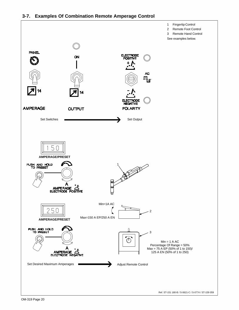
1 Fingertip Control
2 Remote Foot Control
3 Remote Hand Control
See examples below.
1
2
3
Min = 1 A ACPercentage Of Range = 50%
Max = 75 A EP (50% of 1 to 150)/125 A EN (50% of 1 to 250)
AMPERAGE/PRESET
AMPERAGE/PRESET
Set Switches Set Output
Min=1A AC
Max=150 A EP/250 A EN
Set Desired Maximum Amperages Adjust Remote Control

OM-319 Page 21
3-8. AC Balance Control
Ref. ST-151 180-B / S-0865
1 AC Balance Control AndPushbutton
Set Polarity switch to AC. Usepushbutton, control, and Amper-age/Preset meter to change the acoutput square wave. The control re-quires 3 turns to go from minimumto maximum.
Set balance towards 30.0 to obtainmore cleaning action of the work-piece, or towards 90.0 to obtaindeeper penetration of the work-piece. 50.0 (balanced), providesequal penetration and cleaningaction.
1
1
50% Electrode
90% ElectrodeNegative
50% ElectrodeNegative
10% ElectrodePositive
70% ElectrodePositive
30% ElectrodeNegative
Positive
Balance Control Waveform Examples
More Penetration
Balanced
More Cleaning
If Polarity switch is not in AC, the Amper-age/Preset meter goes blank when thepushbutton is pressed.
3-9. AC Frequency Controls
1 AC Frequency Control AndPushbutton
Set Polarity switch to AC. Presspushbutton and use control andAmperage/Preset meter to set acfrequency. Range is 40 to 400hertz. The control requires 3 turnsto go from minimum to maximum.
For most applications, increasingfrequency improves arc stability.
1
If Polarity switch is not in AC, the Amper-age/Preset meter goes blank when thepushbutton is pressed.

OM-319 Page 22
3-10. Postflow Time Control
1 Postflow Time Control
Use control to set the length of timein seconds gas flows after weldingstops.
1
3-11. Start Switch
Ref. S-156 279
1 Start Switch
2 GTAW Electrode
3 Workpiece
With HF on, start arc as follows:
High frequency turns on to helpstart arc when contactor is ener-gized. High frequency turns offwhen arc is started, and turns onwhenever arc is broken to helprestart arc.
With Touch start on, set Polarityswitch to AC or Electrode Negative,and start arc as follows:
Energize contactor, touch tungstenelectrode to workpiece at weld startpoint, hold electrode to work-piece for 1-2 seconds, and slowlylift electrode.
Open-circuit voltage is not presentbefore tungsten electrode touchesworkpiece; only a low sensing volt-age is present. The output contac-tor energizes only after tungstenelectrode is touching workpiece.
2 3
1
Torch Start Example
“Touch” 1–2Seconds
Do NOT Strike Like A Match
3-12. Power Switch
Ref. ST-157 885
1 Power Switch
Use switch to turn unit On and Off.
1
OM-319 Page 23
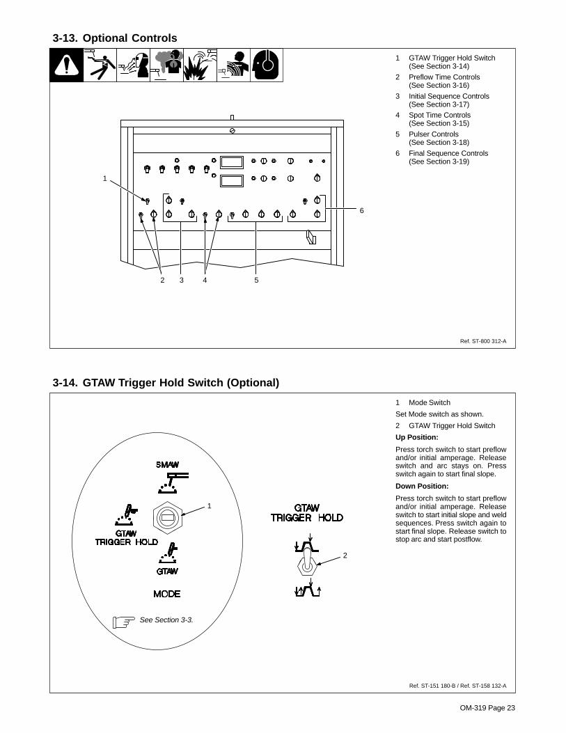
3-13. Optional Controls
Ref. ST-800 312-A
1 GTAW Trigger Hold Switch(See Section 3-14)
2 Preflow Time Controls(See Section 3-16)
3 Initial Sequence Controls(See Section 3-17)
4 Spot Time Controls(See Section 3-15)
5 Pulser Controls(See Section 3-18)
6 Final Sequence Controls(See Section 3-19)
6
3 4 5
1
2
3-14. GTAW Trigger Hold Switch (Optional)
Ref. ST-151 180-B / Ref. ST-158 132-A
1 Mode Switch
Set Mode switch as shown.
2 GTAW Trigger Hold Switch
Up Position:
Press torch switch to start preflowand/or initial amperage. Releaseswitch and arc stays on. Pressswitch again to start final slope.
Down Position:
Press torch switch to start preflowand/or initial amperage. Releaseswitch to start initial slope and weldsequences. Press switch again tostart final slope. Release switch tostop arc and start postflow.
2
1
See Section 3-3.

OM-319 Page 24
3-15. Spot Time Controls (Optional)
Ref. ST-158 132-A
1 Spot Time Switch
On – provides spot time;Off – provides no spot timeOff – for SMAW.
2 Spot Time Control
Use control to set time for GTAWspot welds. Spot time begins at arcinitiation. If arc is broken during spottime cycle, timer stops but does notreset. When spot time has ended,weld output stops. Postflow startswhen remote contactor is opened.Spot timer resets after contactoropens.
1
2
3-16. Preflow Time Controls (Optional)
1 Preflow Time Switch
On – provides preflow time;Off – provides no preflow;Off – for SMAW.
2 Preflow Time Control
Use control to set length of time gasflows before an arc is started.
1
2
3-17. Initial Sequence Controls (Optional)
1 Initial Sequence Switch
On – Initial Sequence control;Off – No Initial Sequence control;Off – for SMAW.
2 Initial Time Control
Use control to set length of time atinitial amperage output beforegoing to Amperage adjustmentcontrols settings output.
3 Initial Amperage Control
Use control to select amperage lev-el for arc starting that is differentthan Amperage adjustment con-trols settings.
4 Initial Slope Time
Use control to set time it takesamperage level to go from initialamperage level at end of initial timeto weld sequence level set byAmperage adjustment controls.
1
2
3
4

OM-319 Page 25
3-18. Pulser Controls (Optional)
1 Pulser Switch
Off – no pulsing;Slow – pulsing, use inside scale ofPulses Per Second control; Fast – pulsing, use outside scale ofPulses Per Second control.Off – for SMAW.
2 Background AmperageControl
Use control to select backgroundamperage during pulsed welding.Background amperage is a per-centage (0 – 100%) of peak amper-age. Peak amperage is setting ofthe Amperage adjustment controls(see Section 3-6).
3 Pulses Per Second Control
Use control to select frequency(number of pulses per second).
4 % On Time Control
Use control to select pulse width,the percentage of a total pulseperiod that is at peak amperage.
See Section 3-20 for an explanationof pulse waveforms.
1 2 3 4
3-19. Final Sequence Controls (Optional)
1 Final Sequence Switch
On – Final Sequence control;Off – no Final Sequence controlOff – for SMAW.
2 Final Amperage Control
Use control to select final sequenceamperage level.
The numbers are a percentage ofthe Amperage adjustment controlsettings (see Section 3-6), and notan actual value.
3 Final Slope Time
Use control to set time to taper weldoutput from level of the Amperageadjustment controls settings to theFinal Amperage level.
4 Final Time Control
Use control to set length of time atfinal amperage before arc turns off.
When using the final sequencecircuit, set Postflow time control(see Section 3-10) for a longer timethan the Final Time control.
1
3
4
2

OM-319 Page 26
3-20. Pulsed Weld Waveforms
S-0259 / Ref. ST-158 132-A
1 Peak Amperage
Peak amperage is the high pulse ofwelding current that heats the weldpuddle.
2 Background Amperage
Background amperage is the lowpulse of welding current that coolsthe weld puddle.
3 Pulse Width (Peak AmperagePeriod)
4 % On Time
The examples show three differentcontrol settings. The stiffness orwetness of the weld puddle iscontrolled by pulse width.
5 One Pulse Period
6 Pulses Per Second
All three examples show a controlsetting of three pulses per second.
7 Background Amperage Period
1
2
53
7
6
4
Example A(50%)
Example B(80%)
Example C(20%)

OM-319 Page 27
SECTION 4 – MAINTENANCE & TROUBLESHOOTING
4-1. Routine Maintenance
� Disconnect power before maintaining.
� Maintain more oftenduring severe conditions.
3 Months
ReplaceDamaged OrUnreadable
Labels
CleanAnd
TightenWeld
Terminals
Replace DamagedGas Hose
Repair Or ReplaceCracked Cables
And Cords
6 Months
Blow Out OrVacuum Inside
OM-319 Page 28
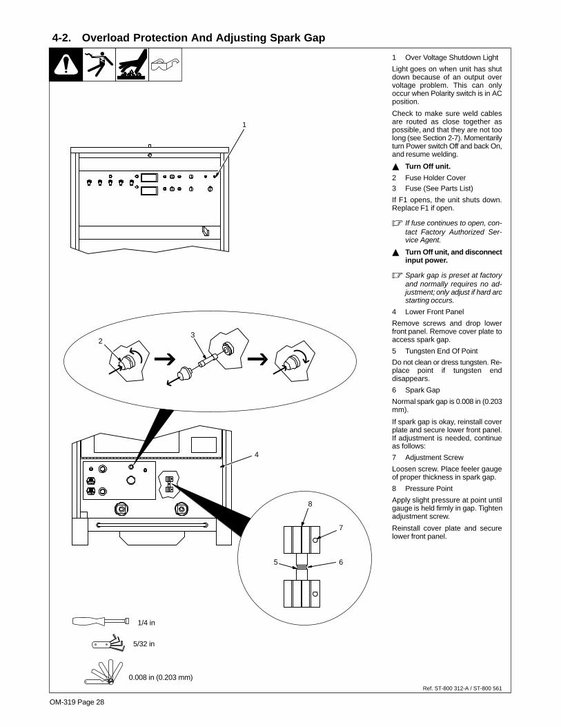
4-2. Overload Protection And Adjusting Spark Gap
Ref. ST-800 312-A / ST-800 561
1 Over Voltage Shutdown Light
Light goes on when unit has shutdown because of an output overvoltage problem. This can onlyoccur when Polarity switch is in ACposition.
Check to make sure weld cablesare routed as close together aspossible, and that they are not toolong (see Section 2-7). Momentarilyturn Power switch Off and back On,and resume welding.
� Turn Off unit.
2 Fuse Holder Cover3 Fuse (See Parts List)
If F1 opens, the unit shuts down.Replace F1 if open.
� If fuse continues to open, con-tact Factory Authorized Ser-vice Agent.
� Turn Off unit, and disconnectinput power.
� Spark gap is preset at factoryand normally requires no ad-justment; only adjust if hard arcstarting occurs.
4 Lower Front Panel
Remove screws and drop lowerfront panel. Remove cover plate toaccess spark gap.
5 Tungsten End Of Point
Do not clean or dress tungsten. Re-place point if tungsten enddisappears.
6 Spark Gap
Normal spark gap is 0.008 in (0.203mm).
If spark gap is okay, reinstall coverplate and secure lower front panel.If adjustment is needed, continueas follows:
7 Adjustment Screw
Loosen screw. Place feeler gaugeof proper thickness in spark gap.
8 Pressure Point
Apply slight pressure at point untilgauge is held firmly in gap. Tightenadjustment screw.
Reinstall cover plate and securelower front panel.
4
8
7
65
1/4 in
5/32 in
0.008 in (0.203 mm)
32
1

OM-319 Page 29
4-3. Troubleshooting
Trouble Remedy
No weld output; unit completelyinoperative.
Place Power switch in On position (see Section 3-12).
Place line disconnect switch in the On position (see Section 2-11).
Check and replace line fuse(s) or reset circuit breaker (see Section 2-11).
Check for proper input connections (see Section 2-11).
Check for proper jumper link positions (see Section 2-10).
Check fuse F1 and replace if necessary (see Section 4-2).
No weld output; fan on. Place Output switch in On position, or place switch in Remote 14 position and connect remote contactorto Remote 14 receptacle (see Sections 3-1 and 2-8).
Check, repair, or replace remote control.
No weld output; fan on; High Tempera-ture light on.
Unit overheated. Allow unit to cool with fans on (see Section 2-3).
No weld output; Over Voltage light on. Over voltage shutdown. Check weld cables, and turn Power switch Off and back On again (see Section4-2).
Erratic or improper weld output. Use proper size and type of weld cable (see Section 2-7).
Clean and tighten all weld connections.
Be sure Polarity switch is in proper position for welding process (see Section 3-2).
No control of weld output. Place Output switch in On position, or place switch in Remote 14 position and connect remote contactorto Remote 14 receptacle (see Sections 3-1 and 2-8).
No output from duplex receptacle RC2. Check, and reset circuit breaker CB1 if necessary (see Section 2-6).
Amperage/Preset meter goes blankwhen presetting Amperage, ACBalance, or AC Frequency.
Be sure Polarity switch is in AC position (see Section 3-2).
No high frequency; difficulty in establish-ing GTAW arc.
Check position of Start switch (see Section 3-11).
Select proper size tungsten.
Be sure that electrode holder cable is not close to any grounded metal.
Check cables and torch for cracked insulation or bad connections. Repair or replace necessary parts.
Check spark gaps and adjust if necessary (see Section 4-2).
Wandering arc – poor control of directionof arc.
Reduce gas flow rate.
Select proper size tungsten.
Properly prepare tungsten.
Tungsten electrode oxidizing and not re-maining bright after conclusion of weld.
Shield weld zone from drafts.
Increase postflow time (see Section 3-10).
Check and tighten all gas fittings.
Properly prepare tungsten.
Replace torch parts if water has leaked into torch.

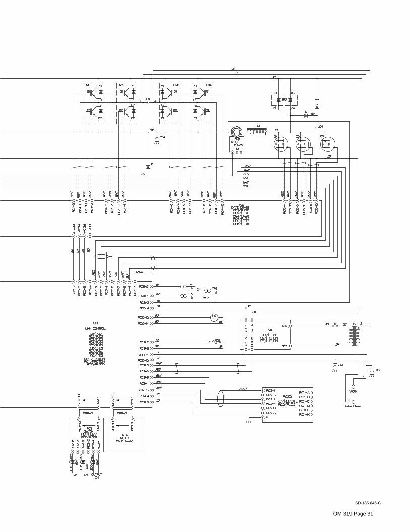
Figure 5-1. Circuit DiagramOM-319 Page 30
SECTION 5 – ELECTRICAL DIAGRAM
OM-319 Page 31
SD-185 645-C

OM-319 Page 32
SECTION 6 – HIGH FREQUENCY
6-1. Welding Processes Requiring High Frequency
high_freq 12/96 – S-0693
1 High-Frequency Voltage
TIG – helps arc jump air gapbetween torch and workpiece and/or stabilize the arc.1
TIG
Work
6-2. Incorrect Installation
50 ft(15 m)
S-0694
Sources of Direct High-FrequencyRadiation1 High-Frequency Source (welding
power source with built-in HF orseparate HF unit)
2 Weld Cables3 Torch4 Work Clamp5 Workpiece6 Work Table
Sources of Conduction of HighFrequency7 Input Power Cable8 Line Disconnect Device9 Input Supply Wiring
Sources of Reradiation of HighFrequency10 Ungrounded Metal Objects11 Lighting12 Wiring13 Water Pipes and Fixtures14 External Phone and Power Lines
Weld Zone
13
9
8
7
1
2
4 5 6
3
10
11, 12
14
OM-319Page 33
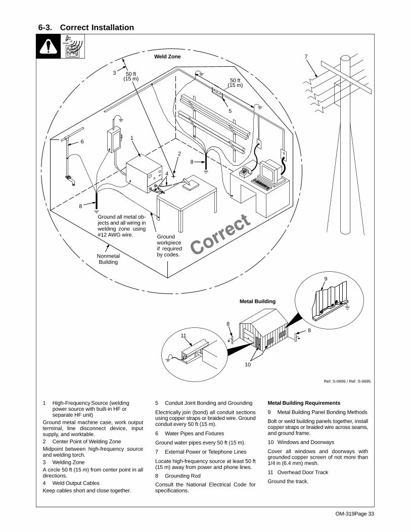
6-3. Correct Installation
1 High-Frequency Source (weldingpower source with built-in HF orseparate HF unit)
Ground metal machine case, work outputterminal, line disconnect device, inputsupply, and worktable.2 Center Point of Welding ZoneMidpoint between high-frequency sourceand welding torch.3 Welding ZoneA circle 50 ft (15 m) from center point in alldirections.4 Weld Output CablesKeep cables short and close together.
5 Conduit Joint Bonding and Grounding
Electrically join (bond) all conduit sectionsusing copper straps or braided wire. Groundconduit every 50 ft (15 m).
6 Water Pipes and Fixtures
Ground water pipes every 50 ft (15 m).
7 External Power or Telephone Lines
Locate high-frequency source at least 50 ft(15 m) away from power and phone lines.
8 Grounding Rod
Consult the National Electrical Code forspecifications.
Metal Building Requirements
9 Metal Building Panel Bonding Methods
Bolt or weld building panels together, installcopper straps or braided wire across seams,and ground frame.
10 Windows and Doorways
Cover all windows and doorways withgrounded copper screen of not more than1/4 in (6.4 mm) mesh.
11 Overhead Door Track
Ground the track.
Ref. S-0695 / Ref. S-0695
1
2
3 50 ft(15 m)
Weld Zone
4
7
50 ft(15 m)
8
5
8
6
Groundworkpieceif requiredby codes.
Ground all metal ob-jects and all wiring inwelding zone using#12 AWG wire.
NonmetalBuilding
9
11
10
Metal Building
88

OM
-319 Page 34
SE
CT
ION
7 – PAR
TS
LIS
T
Fig
ure 7-1. M
ain A
ssemb
lyS
T-800 626-B
�H
ardware is com
mon and
not available unless listed.
56
FIG 7–2 – 55
54
53
5251
50
47 46 4544
4342
41
40
39
37 – FIG 7–3
35
34
33
32
31
30
29
28
27
7
2625
2322
21
20
19
171615
1413
12
11
10
98
765
4
3
FIG 7–4 – 2
1
18
24
36 – FIG 7–5
38
48

OM-319 Page 35
DescriptionPartNo.
Dia.Mkgs.
ItemNo.
Figure 7-1. Main Assembly
Quantity
1 182 126 COVER, top 1. . . . . . . . . . . . . . . . . . . . . . . . . . . . . . . . . . . . . . . . . . . . . . . . . . . . . . . . . . . . . . . . . . . . . . . 2 Fig 7-4 HEAT SINK & BAFFLE ASSEMBLY 1. . . . . . . . . . . . . . . . . . . . . . . . . . . . . . . . . . . . . . . . . . . . . . . . . . . 3 006 426 CLAMP, capacitor 2.000dia 1. . . . . . . . . . . . . . . . . . . . . . . . . . . . . . . . . . . . . . . . . . . . . . . . . . . . . . . . . . 4 168 976 INSULATOR, capacitor 1. . . . . . . . . . . . . . . . . . . . . . . . . . . . . . . . . . . . . . . . . . . . . . . . . . . . . . . . . . . . . 5 C6 093 259 CAPACITOR, elctlt 1000uf 400VDC 1. . . . . . . . . . . . . . . . . . . . . . . . . . . . . . . . . . . . . . . . . . . . . . 6 R5,6 157 981 RESISTOR, WW fxd 375W 161-161 ohm dual 1. . . . . . . . . . . . . . . . . . . . . . . . . . . . . . . . . . . 7 151 179 SUPPORT, lift eye 1. . . . . . . . . . . . . . . . . . . . . . . . . . . . . . . . . . . . . . . . . . . . . . . . . . . . . . . . . . . . . . . . . 8 155 903 BUSHING, lift eye 2. . . . . . . . . . . . . . . . . . . . . . . . . . . . . . . . . . . . . . . . . . . . . . . . . . . . . . . . . . . . . . . . . . 9 026 627 GASKET, lift eye 1. . . . . . . . . . . . . . . . . . . . . . . . . . . . . . . . . . . . . . . . . . . . . . . . . . . . . . . . . . . . . . . . . . .
10 155 905 LIFT EYE 1. . . . . . . . . . . . . . . . . . . . . . . . . . . . . . . . . . . . . . . . . . . . . . . . . . . . . . . . . . . . . . . . . . . . . . . . . 11 086 863 SCREW, .375-16 x 1.000hexwhd 2. . . . . . . . . . . . . . . . . . . . . . . . . . . . . . . . . . . . . . . . . . . . . . . . . . . . 12 PC7 199 825 KIT, circuit card secondary inverter clamp PC7 and cover 1. . . . . . . . . . . . . . . . . . . . . . . . . .
PLG15 148 439 CONNECTOR & SOCKET 1. . . . . . . . . . . . . . . . . . . . . . . . . . . . . . . . . . . . . . . . . . . . . . . . . . . . . 14 110 375 STAND-OFF SUPPORT, PC card No. 6 screw 4. . . . . . . . . . . . . . . . . . . . . . . . . . . . . . . . . . . . . . . . . 15 +151 158 BRACE, rear 1. . . . . . . . . . . . . . . . . . . . . . . . . . . . . . . . . . . . . . . . . . . . . . . . . . . . . . . . . . . . . . . . . . . . . 16 152 582 BRACKET, mtg panel rear 1. . . . . . . . . . . . . . . . . . . . . . . . . . . . . . . . . . . . . . . . . . . . . . . . . . . . . . . . . . 17 126 026 LABEL, warning electric shock can kill 1. . . . . . . . . . . . . . . . . . . . . . . . . . . . . . . . . . . . . . . . . . . . . . . . 18 010 493 BUSHING, snap-in nyl .625 ID x .875mtg hole 1. . . . . . . . . . . . . . . . . . . . . . . . . . . . . . . . . . . . . . . . . 19 025 248 STAND-OFF, insul .250-20 x 1.250 lg x .437thk 2. . . . . . . . . . . . . . . . . . . . . . . . . . . . . . . . . . . . . . . . 20 TE1 038 138 TERMINAL ASSEMBLY, pri 3ph triple voltage (60Hz) (Fig 7-6) 1. . . . . . . . . . . . . . . . . . . . . . 20 TE1 153 017 TERMINAL ASSEMBLY, pri 3ph dual voltage (50Hz) (Fig 7-6) 1. . . . . . . . . . . . . . . . . . . . . . 21 109 035 LABEL, warning electric shock can kill 1. . . . . . . . . . . . . . . . . . . . . . . . . . . . . . . . . . . . . . . . . . . . . . . . 22 +157 875 COVER, channel rear 1. . . . . . . . . . . . . . . . . . . . . . . . . . . . . . . . . . . . . . . . . . . . . . . . . . . . . . . . . . . . . 23 144 758 BRACKET, mtg panel rear 1. . . . . . . . . . . . . . . . . . . . . . . . . . . . . . . . . . . . . . . . . . . . . . . . . . . . . . . . . . 24 CM1 158 197 MODULE, capacitor 1. . . . . . . . . . . . . . . . . . . . . . . . . . . . . . . . . . . . . . . . . . . . . . . . . . . . . . . . . . 25 148 253 BLANK, snap-in nyl 1.750mtg hole 1. . . . . . . . . . . . . . . . . . . . . . . . . . . . . . . . . . . . . . . . . . . . . . . . . . . 26 157 320 SCREW, .375-16 x .750hexwhd 2. . . . . . . . . . . . . . . . . . . . . . . . . . . . . . . . . . . . . . . . . . . . . . . . . . . . . . 27 2T 038 861 BLOCK, term 20A 3P 1. . . . . . . . . . . . . . . . . . . . . . . . . . . . . . . . . . . . . . . . . . . . . . . . . . . . . . . . . . . 28 187 807 BRACKET, mtg motor fan 2. . . . . . . . . . . . . . . . . . . . . . . . . . . . . . . . . . . . . . . . . . . . . . . . . . . . . . . . . . . 29 FM1,2 148 808 MOTOR, fan 230V 50/60Hz 1550RPM .312dia shaft 2. . . . . . . . . . . . . . . . . . . . . . . . . . . . . 30 150 783 BLADE, fan 9 in 5wg 39deg .312 bore CW 2. . . . . . . . . . . . . . . . . . . . . . . . . . . . . . . . . . . . . . . . . . . . 31 088 731 BUSHING, snap-in nyl .375 ID x .500mtg hole 1. . . . . . . . . . . . . . . . . . . . . . . . . . . . . . . . . . . . . . . . . 32 601 872 NUT, .375-16 stl 2. . . . . . . . . . . . . . . . . . . . . . . . . . . . . . . . . . . . . . . . . . . . . . . . . . . . . . . . . . . . . . . . . . . 33 602 213 WASHER, lock .380 ID stl split 2. . . . . . . . . . . . . . . . . . . . . . . . . . . . . . . . . . . . . . . . . . . . . . . . . . . . . . . 34 SR1 142 504 RECTIFIER, si 3ph 300A 400PIV 1. . . . . . . . . . . . . . . . . . . . . . . . . . . . . . . . . . . . . . . . . . . . . . . 35 T1 157 967 TRANSFORMER, pwr main 200/230/460 (60Hz) 1. . . . . . . . . . . . . . . . . . . . . . . . . . . . . . . . . . . 35 T1 164 950 TRANSFORMER, pwr main 230/460/575 (60Hz) 1. . . . . . . . . . . . . . . . . . . . . . . . . . . . . . . . . . . 35 T1 164 954 TRANSFORMER, pwr main 380/415 (50Hz) 1. . . . . . . . . . . . . . . . . . . . . . . . . . . . . . . . . . . . . . .
TP3 119 581 THERMOSTAT, NC 1. . . . . . . . . . . . . . . . . . . . . . . . . . . . . . . . . . . . . . . . . . . . . . . . . . . . . . . . . . . . . . 36 Fig 7-5 PANEL, mtg components 1. . . . . . . . . . . . . . . . . . . . . . . . . . . . . . . . . . . . . . . . . . . . . . . . . . . . . . . . . . . . 37 Fig 7-3 HF PANEL ASSEMBLY 1. . . . . . . . . . . . . . . . . . . . . . . . . . . . . . . . . . . . . . . . . . . . . . . . . . . . . . . . . . . . . . 38 145 784 TAPE, adh dual lock type 400 1.000 wide (order by ft) 1ft. . . . . . . . . . . . . . . . . . . . . . . . . . . . . . . . . . 39 144 762 FOOT, base rear 1. . . . . . . . . . . . . . . . . . . . . . . . . . . . . . . . . . . . . . . . . . . . . . . . . . . . . . . . . . . . . . . . . . . 40 151 161 PANEL, side RH 1. . . . . . . . . . . . . . . . . . . . . . . . . . . . . . . . . . . . . . . . . . . . . . . . . . . . . . . . . . . . . . . . . . . 41 020 279 CLAMP, stl cush .750dia x .281mtg hole 3. . . . . . . . . . . . . . . . . . . . . . . . . . . . . . . . . . . . . . . . . . . . . . 42 157 867 BASE 1. . . . . . . . . . . . . . . . . . . . . . . . . . . . . . . . . . . . . . . . . . . . . . . . . . . . . . . . . . . . . . . . . . . . . . . . . . . . 43 010 141 CLAMP, nyl .250 clamp dia 1. . . . . . . . . . . . . . . . . . . . . . . . . . . . . . . . . . . . . . . . . . . . . . . . . . . . . . . . . . 44 163 108 UPRIGHT, front 1. . . . . . . . . . . . . . . . . . . . . . . . . . . . . . . . . . . . . . . . . . . . . . . . . . . . . . . . . . . . . . . . . . . . 45 010 357 NUT, No. 12 speed x 1.000 lg stl 1. . . . . . . . . . . . . . . . . . . . . . . . . . . . . . . . . . . . . . . . . . . . . . . . . . . . . 46 S1 128 756 SWITCH, tgl 3PST 40A 600VAC 1. . . . . . . . . . . . . . . . . . . . . . . . . . . . . . . . . . . . . . . . . . . . . . . . . 47 146 684 INSULATOR, switch pwr 1. . . . . . . . . . . . . . . . . . . . . . . . . . . . . . . . . . . . . . . . . . . . . . . . . . . . . . . . . . . . 48 127 363 LABEL, warning electric shock can kill 1. . . . . . . . . . . . . . . . . . . . . . . . . . . . . . . . . . . . . . . . . . . . . . . . 49 +164 348 INSULATOR, output stud 1. . . . . . . . . . . . . . . . . . . . . . . . . . . . . . . . . . . . . . . . . . . . . . . . . . . . . . . . . . 50 145 783 TAPE, adh dual lock type 170 1.000 wide (order by ft) 1ft. . . . . . . . . . . . . . . . . . . . . . . . . . . . . . . . . . 51 +144 753 DOOR, HF control 1. . . . . . . . . . . . . . . . . . . . . . . . . . . . . . . . . . . . . . . . . . . . . . . . . . . . . . . . . . . . . . . . 52 134 327 LABEL, warning general precautionary 1. . . . . . . . . . . . . . . . . . . . . . . . . . . . . . . . . . . . . . . . . . . . . . . . 53 151 162 PANEL, door switch 1. . . . . . . . . . . . . . . . . . . . . . . . . . . . . . . . . . . . . . . . . . . . . . . . . . . . . . . . . . . . . . . .

OM-319 Page 36
DescriptionPartNo.
Dia.Mkgs.
ItemNo.
Figure 7-1. Main Assembly (Continued)
Quantity
54 NAMEPLATE, (order by model and serial number) 1. . . . . . . . . . . . . . . . . . . . . . . . . . . . . . . . . . . . . . . . . . . . . . 55 Fig 7-2 MODULE, electronics box 1. . . . . . . . . . . . . . . . . . . . . . . . . . . . . . . . . . . . . . . . . . . . . . . . . . . . . . . . . . . . 56 151 160 PANEL, side LH 1. . . . . . . . . . . . . . . . . . . . . . . . . . . . . . . . . . . . . . . . . . . . . . . . . . . . . . . . . . . . . . . . . . .
+When ordering a component originally displaying a precautionary label, the label should also be ordered.To maintain the factory original performance of your equipment, use only Manufacturer’s SuggestedReplacement Parts. Model and serial number required when ordering parts from your local distributor.
ST-800 553-A
1 23
4
5
6 7
8
9 10
11
12
13 14 15
1316
1718
19
20
21
22
23
24
25
262728
29
30
31323332
34353637
3839
40
� Hardware is common andnot available unless listed.
Figure 7-2. Module, Electronics Box

OM-319 Page 37
DescriptionPartNo.
Dia.Mkgs.
ItemNo.
Figure 7-2. Module, Electronics Box (Fig 7-1 Item 55)
Quantity
1 107 551 STRAIN RELIEF, cover 2. . . . . . . . . . . . . . . . . . . . . . . . . . . . . . . . . . . . . . . . . . . . . . . . . . . . . . . . . . . . . 2 158 190 DOOR, electronics box 1. . . . . . . . . . . . . . . . . . . . . . . . . . . . . . . . . . . . . . . . . . . . . . . . . . . . . . . . . . . . . 3 010 853 FASTENER, screw sltd hd No. 12 1. . . . . . . . . . . . . . . . . . . . . . . . . . . . . . . . . . . . . . . . . . . . . . . . . . . . 4 010 855 RETAINER, screw No. 12 1. . . . . . . . . . . . . . . . . . . . . . . . . . . . . . . . . . . . . . . . . . . . . . . . . . . . . . . . . . . 5 PLG2,17 164 738 CABLE, ribbon 10posn 1. . . . . . . . . . . . . . . . . . . . . . . . . . . . . . . . . . . . . . . . . . . . . . . . . . . . 6 PC3 164 775 CIRCUIT CARD, switch 1. . . . . . . . . . . . . . . . . . . . . . . . . . . . . . . . . . . . . . . . . . . . . . . . . . . . . . . .
PLG39 153 501 CONNECTOR & SOCKETS 1. . . . . . . . . . . . . . . . . . . . . . . . . . . . . . . . . . . . . . . . . . . . . . . . . . . . 7 110 375 STAND-OFF SUPPORT, PC card No. 6 screw 4. . . . . . . . . . . . . . . . . . . . . . . . . . . . . . . . . . . . . . . . . 8 PLG3,29 155 511 CABLE, ribbon 10posn 16.000 lg 1. . . . . . . . . . . . . . . . . . . . . . . . . . . . . . . . . . . . . . . . . . . . 9 PC4 164 606 CIRCUIT CARD, meter 1. . . . . . . . . . . . . . . . . . . . . . . . . . . . . . . . . . . . . . . . . . . . . . . . . . . . . . . .
10 PC6 164 771 CIRCUIT CARD, potentiometer top 1. . . . . . . . . . . . . . . . . . . . . . . . . . . . . . . . . . . . . . . . . . . . . . PLG24 164 899 CONNECTOR & SOCKETS 1. . . . . . . . . . . . . . . . . . . . . . . . . . . . . . . . . . . . . . . . . . . . . . . . . . . .
11 PC1 186 073 CIRCUIT CARD, control 1. . . . . . . . . . . . . . . . . . . . . . . . . . . . . . . . . . . . . . . . . . . . . . . . . . . . . . . PLG5 148 439 CONNECTOR & SOCKETS 1. . . . . . . . . . . . . . . . . . . . . . . . . . . . . . . . . . . . . . . . . . . . . . . . . . . . . PLG7 168 847 CONNECTOR & SOCKETS 1. . . . . . . . . . . . . . . . . . . . . . . . . . . . . . . . . . . . . . . . . . . . . . . . . . . . .
12 183 656 ELECTRONICS BOX 1. . . . . . . . . . . . . . . . . . . . . . . . . . . . . . . . . . . . . . . . . . . . . . . . . . . . . . . . . . . . . . . 13 168 262 STAND-OFF SUPPORT, PC card .312/.375 17. . . . . . . . . . . . . . . . . . . . . . . . . . . . . . . . . . . . . . . . . . . 14 010 146 CLAMP, nyl .625 clamp dia 2. . . . . . . . . . . . . . . . . . . . . . . . . . . . . . . . . . . . . . . . . . . . . . . . . . . . . . . . . . 15 PC2 189 399 CIRCUIT CARD, driver 1. . . . . . . . . . . . . . . . . . . . . . . . . . . . . . . . . . . . . . . . . . . . . . . . . . . . . . . .
PLG10,11 164 899 CONNECTOR & SOCKETS 1. . . . . . . . . . . . . . . . . . . . . . . . . . . . . . . . . . . . . . . . . . . . . . . . . . PLG12 131 052 CONNECTOR & SOCKETS 1. . . . . . . . . . . . . . . . . . . . . . . . . . . . . . . . . . . . . . . . . . . . . . . . . . . . PLG13 130 203 CONNECTOR & SOCKETS 1. . . . . . . . . . . . . . . . . . . . . . . . . . . . . . . . . . . . . . . . . . . . . . . . . . . .
PLG14,16 153 501 CONNECTOR & SOCKETS 1. . . . . . . . . . . . . . . . . . . . . . . . . . . . . . . . . . . . . . . . . . . . . . . . . . 16 010 494 BUSHING, snap-in nyl 1.000 ID x 1.125mtg hole 2. . . . . . . . . . . . . . . . . . . . . . . . . . . . . . . . . . . . . . . 17 PC22 ♦164 514 CIRCUIT CARD, option panel 1. . . . . . . . . . . . . . . . . . . . . . . . . . . . . . . . . . . . . . . . . . . . . . . 18 PLG33,46 ♦158 349 CABLE, ribbon 24posn 4.000 in 1. . . . . . . . . . . . . . . . . . . . . . . . . . . . . . . . . . . . . . . . . . 19 PLG4,22,23 164 739 CABLE, ribbon 14posn 1. . . . . . . . . . . . . . . . . . . . . . . . . . . . . . . . . . . . . . . . . . . . . . . . . 20 PC5 164 767 CIRCUIT CARD, potentiometer bottom 1. . . . . . . . . . . . . . . . . . . . . . . . . . . . . . . . . . . . . . . . . . 21 158 191 STRIP, electronics box 1. . . . . . . . . . . . . . . . . . . . . . . . . . . . . . . . . . . . . . . . . . . . . . . . . . . . . . . . . . . . . . 22 PLG40,44,45 ♦158 347 CABLE, ribbon 24posn 20.000 in 1. . . . . . . . . . . . . . . . . . . . . . . . . . . . . . . . . . . . . 23 PC24 ♦158 050 CIRCUIT CARD, switch/potentiometer 1. . . . . . . . . . . . . . . . . . . . . . . . . . . . . . . . . . . . . . . . 24 PLG41-43 ♦158 348 CABLE, ribbon 24posn 14.000 in 1. . . . . . . . . . . . . . . . . . . . . . . . . . . . . . . . . . . . . . . . 25 PC23 ♦158 047 CIRCUIT CARD, switch/potentiometer 1. . . . . . . . . . . . . . . . . . . . . . . . . . . . . . . . . . . . . . . . 26 158 324 PLATE, panel control 1. . . . . . . . . . . . . . . . . . . . . . . . . . . . . . . . . . . . . . . . . . . . . . . . . . . . . . . . . . . . . . . 26 ♦158 132 PLATE, sequencer 1. . . . . . . . . . . . . . . . . . . . . . . . . . . . . . . . . . . . . . . . . . . . . . . . . . . . . . . . . . . . . . . 27 ♦115 360 KNOB, arrow 11. . . . . . . . . . . . . . . . . . . . . . . . . . . . . . . . . . . . . . . . . . . . . . . . . . . . . . . . . . . . . . . . . . . . 28 ♦115 359 CAP, peaked 11. . . . . . . . . . . . . . . . . . . . . . . . . . . . . . . . . . . . . . . . . . . . . . . . . . . . . . . . . . . . . . . . . . . . 29 PC25 ♦158 056 CIRCUIT CARD, switch/potentiometer 1. . . . . . . . . . . . . . . . . . . . . . . . . . . . . . . . . . . . . . . . 30 PC26 ♦158 053 CIRCUIT CARD, switch/potentiometer 1. . . . . . . . . . . . . . . . . . . . . . . . . . . . . . . . . . . . . . . . 31 154 339 KNOB, arrow 1. . . . . . . . . . . . . . . . . . . . . . . . . . . . . . . . . . . . . . . . . . . . . . . . . . . . . . . . . . . . . . . . . . . . . . 32 115 359 CAP, peaked 5. . . . . . . . . . . . . . . . . . . . . . . . . . . . . . . . . . . . . . . . . . . . . . . . . . . . . . . . . . . . . . . . . . . . . . 33 LED1,2 170 928 LED, yellow 10mA 5V 2. . . . . . . . . . . . . . . . . . . . . . . . . . . . . . . . . . . . . . . . . . . . . . . . . . . . . . 34 164 689 KNOB, plastic 4. . . . . . . . . . . . . . . . . . . . . . . . . . . . . . . . . . . . . . . . . . . . . . . . . . . . . . . . . . . . . . . . . . . . . 35 153 195 NUT, .250-40 4. . . . . . . . . . . . . . . . . . . . . . . . . . . . . . . . . . . . . . . . . . . . . . . . . . . . . . . . . . . . . . . . . . . . . . 36 150 981 BUTTON, switch black 4. . . . . . . . . . . . . . . . . . . . . . . . . . . . . . . . . . . . . . . . . . . . . . . . . . . . . . . . . . . . . . 37 071 230 BEZEL/FILTER, black bezel/red filter 2.000 viewing 2. . . . . . . . . . . . . . . . . . . . . . . . . . . . . . . . . . . . 38 LED3,4 170 927 LED, green 10mA 5V 2. . . . . . . . . . . . . . . . . . . . . . . . . . . . . . . . . . . . . . . . . . . . . . . . . . . . . . . 39 151 180 PLATE, ident control 1. . . . . . . . . . . . . . . . . . . . . . . . . . . . . . . . . . . . . . . . . . . . . . . . . . . . . . . . . . . . . . . 40 LED5 170 926 LED, blue 45mA 3.4V 1. . . . . . . . . . . . . . . . . . . . . . . . . . . . . . . . . . . . . . . . . . . . . . . . . . . . . . . .
♦Part of 042 888 Optional Aerowave Full Feature Module.To maintain the factory original performance of your equipment, use only Manufacturer’s SuggestedReplacement Parts. Model and serial number required when ordering parts from your local distributor.

OM-319 Page 38
ST-800 685-B
1 2 3
4
5
6
78
9
11 12
13
14
15
15
17
18
13
10
16
� Hardware is common andnot available unless listed.
Figure 7-3. HF Panel Assembly

OM-319 Page 39
DescriptionPartNo.
Dia.Mkgs.
ItemNo.
Figure 7-3. HF Panel Assembly (Fig 7-1 Item 37)
Quantity
1 CB1 093 995 CIRCUIT BREAKER, man reset 1P 15A 250VAC 1. . . . . . . . . . . . . . . . . . . . . . . . . . . . . . . . . 2 C7 135 664 CAPACITOR, cer disc .01uf 500VAC 1. . . . . . . . . . . . . . . . . . . . . . . . . . . . . . . . . . . . . . . . . . . . . 3 RC2 604 176 RECEPTACLE, str dx grd 2P3W 15A 125V 1. . . . . . . . . . . . . . . . . . . . . . . . . . . . . . . . . . . . . . 4 GS1 174 890 VALVE ASSEMBLY, 24VAC 2 way 1/4 IPS 1/8 orf 1. . . . . . . . . . . . . . . . . . . . . . . . . . . . . . . . 5 PC10,RC2 157 959 CIRCUIT CARD ASSEMBLY, connector/receptacle 1. . . . . . . . . . . . . . . . . . . . . . . . . . 6 185 684 PANEL, HF 1. . . . . . . . . . . . . . . . . . . . . . . . . . . . . . . . . . . . . . . . . . . . . . . . . . . . . . . . . . . . . . . . . . . . . . . 7 103 947 TUBING, stl .312 OD x 17ga wall x .937 lg 2. . . . . . . . . . . . . . . . . . . . . . . . . . . . . . . . . . . . . . . . . . . . 8 G 181 464 SPARK GAP ASSEMBLY 2. . . . . . . . . . . . . . . . . . . . . . . . . . . . . . . . . . . . . . . . . . . . . . . . . . . . . . . . 9 151 173 COVER, HF 1. . . . . . . . . . . . . . . . . . . . . . . . . . . . . . . . . . . . . . . . . . . . . . . . . . . . . . . . . . . . . . . . . . . . . . .
10 C12 185 640 CAPACITOR ASSEMBLY 1. . . . . . . . . . . . . . . . . . . . . . . . . . . . . . . . . . . . . . . . . . . . . . . . . . . . . . 11 T3 155 792 ARC STARTER, pulsed HF 1. . . . . . . . . . . . . . . . . . . . . . . . . . . . . . . . . . . . . . . . . . . . . . . . . . . . . 12 PC8 158 137 CIRCUIT CARD, arc starter 1. . . . . . . . . . . . . . . . . . . . . . . . . . . . . . . . . . . . . . . . . . . . . . . . . . . .
PLG38 153 501 CONNECTOR & SOCKETS 1. . . . . . . . . . . . . . . . . . . . . . . . . . . . . . . . . . . . . . . . . . . . . . . . . . . . 13 151 169 PANEL, front HF control box 1. . . . . . . . . . . . . . . . . . . . . . . . . . . . . . . . . . . . . . . . . . . . . . . . . . . . . . . . . 14 134 201 STAND-OFF SUPPORT, PC card .312/.375 6. . . . . . . . . . . . . . . . . . . . . . . . . . . . . . . . . . . . . . . . . . . 15 039 047 TERMINAL, pwr output red (consisting of) 3. . . . . . . . . . . . . . . . . . . . . . . . . . . . . . . . . . . . . . . . . . . . .
601 879 NUT, .500-13 x .44 high stl 1. . . . . . . . . . . . . . . . . . . . . . . . . . . . . . . . . . . . . . . . . . . . . . . . . . . . . . . . . . . . . 601 880 NUT, .500-13 x .31 high stl 1. . . . . . . . . . . . . . . . . . . . . . . . . . . . . . . . . . . . . . . . . . . . . . . . . . . . . . . . . . . . .
16 C13 132 433 CAPACITOR ASSEMBLY 1. . . . . . . . . . . . . . . . . . . . . . . . . . . . . . . . . . . . . . . . . . . . . . . . . . . . . . 17 046 432 HOLDER, fuse mintr .250 x 1.250 1. . . . . . . . . . . . . . . . . . . . . . . . . . . . . . . . . . . . . . . . . . . . . . . . . . . . 18 F1 *012 643 FUSE, mintr gl slo-blo 1A 250V 1. . . . . . . . . . . . . . . . . . . . . . . . . . . . . . . . . . . . . . . . . . . . . . . . .
PLG30 152 249 CONNECTOR & SOCKETS 1. . . . . . . . . . . . . . . . . . . . . . . . . . . . . . . . . . . . . . . . . . . . . . . . . . . . PLG31 168 846 CONNECTOR & PINS 1. . . . . . . . . . . . . . . . . . . . . . . . . . . . . . . . . . . . . . . . . . . . . . . . . . . . . . . . .
*Recommended Spare Parts.To maintain the factory original performance of your equipment, use only Manufacturer’s SuggestedReplacement Parts. Model and serial number required when ordering parts from your local distributor.

OM-319 Page 40
1 2
3 5
6
7
54
1
891011
12
13
14
15
1617
14
18
19
20
ST-800 683
� Hardware is common andnot available unless listed.
Figure 7-4. Heat Sink & Baffle Assembly
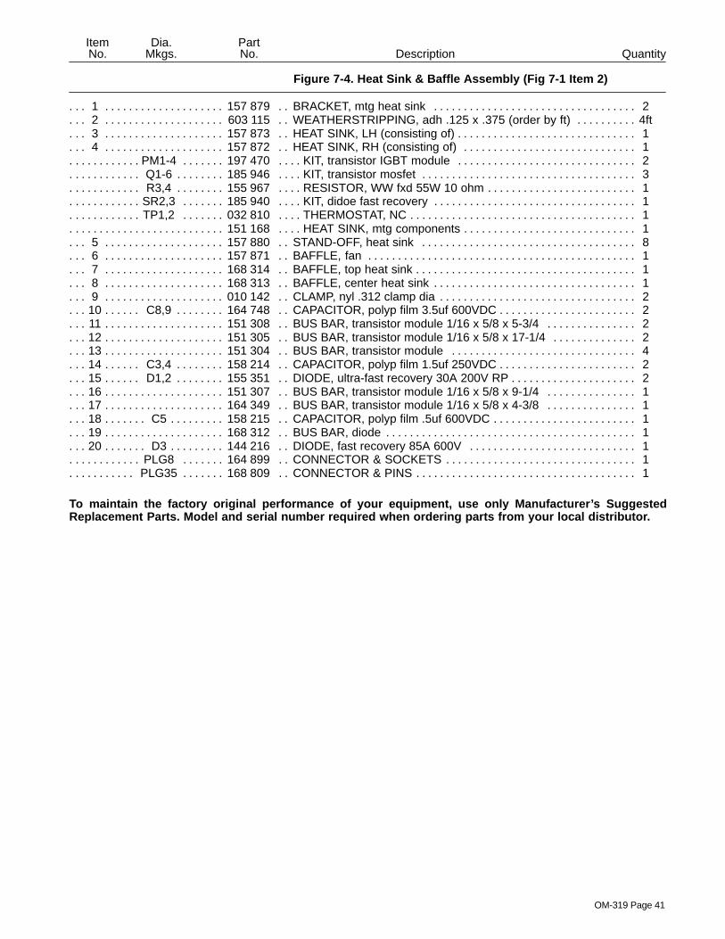
OM-319 Page 41
Figure 7-4. Heat Sink & Baffle Assembly (Fig 7-1 Item 2)
DescriptionPartNo.
Dia.Mkgs.
ItemNo. Quantity
1 157 879 BRACKET, mtg heat sink 2. . . . . . . . . . . . . . . . . . . . . . . . . . . . . . . . . . . . . . . . . . . . . . . . . . . . . . . . . . . 2 603 115 WEATHERSTRIPPING, adh .125 x .375 (order by ft) 4ft. . . . . . . . . . . . . . . . . . . . . . . . . . . . . . . . . . . 3 157 873 HEAT SINK, LH (consisting of) 1. . . . . . . . . . . . . . . . . . . . . . . . . . . . . . . . . . . . . . . . . . . . . . . . . . . . . . . 4 157 872 HEAT SINK, RH (consisting of) 1. . . . . . . . . . . . . . . . . . . . . . . . . . . . . . . . . . . . . . . . . . . . . . . . . . . . . .
PM1-4 197 470 KIT, transistor IGBT module 2. . . . . . . . . . . . . . . . . . . . . . . . . . . . . . . . . . . . . . . . . . . . . . . . . . . . . Q1-6 185 946 KIT, transistor mosfet 3. . . . . . . . . . . . . . . . . . . . . . . . . . . . . . . . . . . . . . . . . . . . . . . . . . . . . . . . . . . . R3,4 155 967 RESISTOR, WW fxd 55W 10 ohm 1. . . . . . . . . . . . . . . . . . . . . . . . . . . . . . . . . . . . . . . . . . . . . . . . .
SR2,3 185 940 KIT, didoe fast recovery 1. . . . . . . . . . . . . . . . . . . . . . . . . . . . . . . . . . . . . . . . . . . . . . . . . . . . . . . . . TP1,2 032 810 THERMOSTAT, NC 1. . . . . . . . . . . . . . . . . . . . . . . . . . . . . . . . . . . . . . . . . . . . . . . . . . . . . . . . . . . . .
151 168 HEAT SINK, mtg components 1. . . . . . . . . . . . . . . . . . . . . . . . . . . . . . . . . . . . . . . . . . . . . . . . . . . . . . . . . . . 5 157 880 STAND-OFF, heat sink 8. . . . . . . . . . . . . . . . . . . . . . . . . . . . . . . . . . . . . . . . . . . . . . . . . . . . . . . . . . . . . 6 157 871 BAFFLE, fan 1. . . . . . . . . . . . . . . . . . . . . . . . . . . . . . . . . . . . . . . . . . . . . . . . . . . . . . . . . . . . . . . . . . . . . . 7 168 314 BAFFLE, top heat sink 1. . . . . . . . . . . . . . . . . . . . . . . . . . . . . . . . . . . . . . . . . . . . . . . . . . . . . . . . . . . . . . 8 168 313 BAFFLE, center heat sink 1. . . . . . . . . . . . . . . . . . . . . . . . . . . . . . . . . . . . . . . . . . . . . . . . . . . . . . . . . . . 9 010 142 CLAMP, nyl .312 clamp dia 2. . . . . . . . . . . . . . . . . . . . . . . . . . . . . . . . . . . . . . . . . . . . . . . . . . . . . . . . . .
10 C8,9 164 748 CAPACITOR, polyp film 3.5uf 600VDC 2. . . . . . . . . . . . . . . . . . . . . . . . . . . . . . . . . . . . . . . . . . 11 151 308 BUS BAR, transistor module 1/16 x 5/8 x 5-3/4 2. . . . . . . . . . . . . . . . . . . . . . . . . . . . . . . . . . . . . . . . 12 151 305 BUS BAR, transistor module 1/16 x 5/8 x 17-1/4 2. . . . . . . . . . . . . . . . . . . . . . . . . . . . . . . . . . . . . . . 13 151 304 BUS BAR, transistor module 4. . . . . . . . . . . . . . . . . . . . . . . . . . . . . . . . . . . . . . . . . . . . . . . . . . . . . . . . 14 C3,4 158 214 CAPACITOR, polyp film 1.5uf 250VDC 2. . . . . . . . . . . . . . . . . . . . . . . . . . . . . . . . . . . . . . . . . . 15 D1,2 155 351 DIODE, ultra-fast recovery 30A 200V RP 2. . . . . . . . . . . . . . . . . . . . . . . . . . . . . . . . . . . . . . . . 16 151 307 BUS BAR, transistor module 1/16 x 5/8 x 9-1/4 1. . . . . . . . . . . . . . . . . . . . . . . . . . . . . . . . . . . . . . . . 17 164 349 BUS BAR, transistor module 1/16 x 5/8 x 4-3/8 1. . . . . . . . . . . . . . . . . . . . . . . . . . . . . . . . . . . . . . . . 18 C5 158 215 CAPACITOR, polyp film .5uf 600VDC 1. . . . . . . . . . . . . . . . . . . . . . . . . . . . . . . . . . . . . . . . . . . . . 19 168 312 BUS BAR, diode 1. . . . . . . . . . . . . . . . . . . . . . . . . . . . . . . . . . . . . . . . . . . . . . . . . . . . . . . . . . . . . . . . . . . 20 D3 144 216 DIODE, fast recovery 85A 600V 1. . . . . . . . . . . . . . . . . . . . . . . . . . . . . . . . . . . . . . . . . . . . . . . . .
PLG8 164 899 CONNECTOR & SOCKETS 1. . . . . . . . . . . . . . . . . . . . . . . . . . . . . . . . . . . . . . . . . . . . . . . . . . . . . PLG35 168 809 CONNECTOR & PINS 1. . . . . . . . . . . . . . . . . . . . . . . . . . . . . . . . . . . . . . . . . . . . . . . . . . . . . . . . .
To maintain the factory original performance of your equipment, use only Manufacturer’s SuggestedReplacement Parts. Model and serial number required when ordering parts from your local distributor.
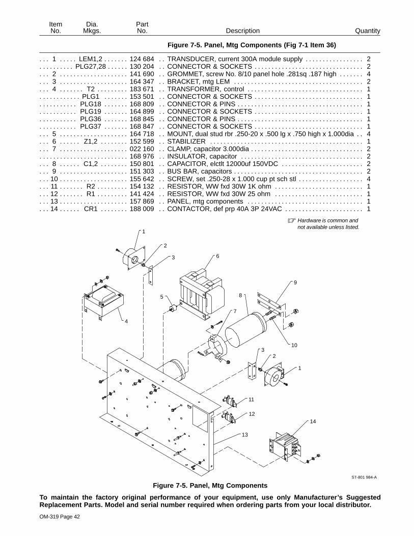
OM-319 Page 42
Figure 7-5. Panel, Mtg Components (Fig 7-1 Item 36)
DescriptionPartNo.
Dia.Mkgs.
ItemNo. Quantity
1 LEM1,2 124 684 TRANSDUCER, current 300A module supply 2. . . . . . . . . . . . . . . . . . . . . . . . . . . . . . . . . . PLG27,28 130 204 CONNECTOR & SOCKETS 2. . . . . . . . . . . . . . . . . . . . . . . . . . . . . . . . . . . . . . . . . . . . . . . . . .
2 141 690 GROMMET, screw No. 8/10 panel hole .281sq .187 high 4. . . . . . . . . . . . . . . . . . . . . . . . . . . . . . . . 3 164 347 BRACKET, mtg LEM 2. . . . . . . . . . . . . . . . . . . . . . . . . . . . . . . . . . . . . . . . . . . . . . . . . . . . . . . . . . . . . . . 4 T2 183 671 TRANSFORMER, control 1. . . . . . . . . . . . . . . . . . . . . . . . . . . . . . . . . . . . . . . . . . . . . . . . . . . . . . .
PLG1 153 501 CONNECTOR & SOCKETS 1. . . . . . . . . . . . . . . . . . . . . . . . . . . . . . . . . . . . . . . . . . . . . . . . . . . . . PLG18 168 809 CONNECTOR & PINS 1. . . . . . . . . . . . . . . . . . . . . . . . . . . . . . . . . . . . . . . . . . . . . . . . . . . . . . . . . PLG19 164 899 CONNECTOR & SOCKETS 1. . . . . . . . . . . . . . . . . . . . . . . . . . . . . . . . . . . . . . . . . . . . . . . . . . . . PLG36 168 845 CONNECTOR & PINS 1. . . . . . . . . . . . . . . . . . . . . . . . . . . . . . . . . . . . . . . . . . . . . . . . . . . . . . . . . PLG37 168 847 CONNECTOR & SOCKETS 1. . . . . . . . . . . . . . . . . . . . . . . . . . . . . . . . . . . . . . . . . . . . . . . . . . . .
5 164 718 MOUNT, dual stud rbr .250-20 x .500 lg x .750 high x 1.000dia 4. . . . . . . . . . . . . . . . . . . . . . . . . . . 6 Z1,2 152 599 STABILIZER 1. . . . . . . . . . . . . . . . . . . . . . . . . . . . . . . . . . . . . . . . . . . . . . . . . . . . . . . . . . . . . . . . 7 022 160 CLAMP, capacitor 3.000dia 2. . . . . . . . . . . . . . . . . . . . . . . . . . . . . . . . . . . . . . . . . . . . . . . . . . . . . . . . . .
168 976 INSULATOR, capacitor 2. . . . . . . . . . . . . . . . . . . . . . . . . . . . . . . . . . . . . . . . . . . . . . . . . . . . . . . . . . . . . . . . 8 C1,2 150 801 CAPACITOR, elctlt 12000uf 150VDC 2. . . . . . . . . . . . . . . . . . . . . . . . . . . . . . . . . . . . . . . . . . . 9 151 303 BUS BAR, capacitors 2. . . . . . . . . . . . . . . . . . . . . . . . . . . . . . . . . . . . . . . . . . . . . . . . . . . . . . . . . . . . . . .
10 155 642 SCREW, set .250-28 x 1.000 cup pt sch stl 4. . . . . . . . . . . . . . . . . . . . . . . . . . . . . . . . . . . . . . . . . . . . 11 R2 154 132 RESISTOR, WW fxd 30W 1K ohm 1. . . . . . . . . . . . . . . . . . . . . . . . . . . . . . . . . . . . . . . . . . . . . . . 12 R1 141 424 RESISTOR, WW fxd 30W 25 ohm 1. . . . . . . . . . . . . . . . . . . . . . . . . . . . . . . . . . . . . . . . . . . . . . . 13 157 869 PANEL, mtg components 1. . . . . . . . . . . . . . . . . . . . . . . . . . . . . . . . . . . . . . . . . . . . . . . . . . . . . . . . . . . 14 CR1 188 009 CONTACTOR, def prp 40A 3P 24VAC 1. . . . . . . . . . . . . . . . . . . . . . . . . . . . . . . . . . . . . . . . . .
ST-801 984-A
� Hardware is common andnot available unless listed.
1
2
3
4
5
6
7
8
9
103
2
1
11
12
13
14
Figure 7-5. Panel, Mtg Components
To maintain the factory original performance of your equipment, use only Manufacturer’s SuggestedReplacement Parts. Model and serial number required when ordering parts from your local distributor.

OM-319 Page 43
QuantityDescriptionPartNo.
ItemNo.
Figure 7-6. Terminal Assembly, Primary (Fig 7-1 Item 20) 038 138 153 017
1 601 835 NUT,10-32 brs 36 24. . . . . . . . . . . . . . . . . . . . . . . . . . . . . . . . . . . . . . . . . . . . . . . . . . . . . . . . . . . . . . . . . . 2 038 058 TERMINAL BOARD, primary 1 1. . . . . . . . . . . . . . . . . . . . . . . . . . . . . . . . . . . . . . . . . . . . . . . . . . . . . . . 3 038 887 STUD, pri bd brs 10-32 x 1.375 18 12. . . . . . . . . . . . . . . . . . . . . . . . . . . . . . . . . . . . . . . . . . . . . . . . . . . 4 010 913 WASHER, flat .218 ID brs 18 12. . . . . . . . . . . . . . . . . . . . . . . . . . . . . . . . . . . . . . . . . . . . . . . . . . . . . . . . 5 038 618 LINK, jumper term bd pri 6 6. . . . . . . . . . . . . . . . . . . . . . . . . . . . . . . . . . . . . . . . . . . . . . . . . . . . . . . . . . . 6 601 836 NUT, .250-20 brs 6 6. . . . . . . . . . . . . . . . . . . . . . . . . . . . . . . . . . . . . . . . . . . . . . . . . . . . . . . . . . . . . . . . . . 7 010 915 WASHER, flat .250 ID brs 6 6. . . . . . . . . . . . . . . . . . . . . . . . . . . . . . . . . . . . . . . . . . . . . . . . . . . . . . . . . . 8 038 888 STUD, pri bd brs .250-20 x 1.500 3 3. . . . . . . . . . . . . . . . . . . . . . . . . . . . . . . . . . . . . . . . . . . . . . . . . . .
1
3
45
6
78
2
67
SA-138 574
� Hardware is common andnot available unless listed.
Figure 7-6. Terminal Assembly, Primary
To maintain the factory original performance of your equipment, use only Manufacturer’s SuggestedReplacement Parts. Model and serial number required when ordering parts from your local distributor.

OM-319 Page 44
Notes


Warranty Questions?
Call1-800-4-A-MILLERfor your localMiller distributor.
miller_warr 7/00
Your distributor also givesyou ...
ServiceYou always get the fast,reliable response youneed. Most replacementparts can be in yourhands in 24 hours.
SupportNeed fast answers to thetough welding questions?Contact your distributor.The expertise of thedistributor and Miller isthere to help you, everystep of the way.
Effective January 1, 2000(Equipment with a serial number preface of “LA” or newer)This limited warranty supersedes all previous Miller warranties and is exclusive with no other
guarantees or warranties expressed or implied.
LIMITED WARRANTY – Subject to the terms and conditionsbelow, Miller Electric Mfg. Co., Appleton, Wisconsin, warrantsto its original retail purchaser that new Miller equipment soldafter the effective date of this limited warranty is free of defectsin material and workmanship at the time it is shipped by Miller.THIS WARRANTY IS EXPRESSLY IN LIEU OF ALL OTHERWARRANTIES, EXPRESS OR IMPLIED, INCLUDING THEWARRANTIES OF MERCHANTABILITY AND FITNESS.
Within the warranty periods listed below, Miller will repair orreplace any warranted parts or components that fail due tosuch defects in material or workmanship. Miller must benotified in writing within thirty (30) days of such defect orfailure, at which time Miller will provide instructions on thewarranty claim procedures to be followed.
Miller shall honor warranty claims on warranted equipmentlisted below in the event of such a failure within the warrantytime periods. All warranty time periods start on the date thatthe equipment was delivered to the original retail purchaser, orone year after the equipment is sent to a North Americandistributor or eighteen months after the equipment is sent to anInternational distributor.
1. 5 Years Parts – 3 Years Labor
* Original main power rectifiers* Inverters (input and output rectifiers only)
2. 3 Years — Parts and Labor
* Transformer/Rectifier Power Sources* Plasma Arc Cutting Power Sources* Semi-Automatic and Automatic Wire Feeders* Inverter Power Supplies* Intellitig* Engine Driven Welding Generators
(NOTE: Engines are warranted separately bythe engine manufacturer.)
3. 1 Year — Parts and Labor
* DS-2 Wire Feeder* Motor Driven Guns (w/exception of Spoolmate
185 & Spoolmate 250)* Process Controllers* Positioners and Controllers* Automatic Motion Devices* RFCS Foot Controls* Induction Heating Power Sources* Water Coolant Systems* HF Units* Grids* Maxstar 140* Spot Welders* Load Banks* Miller Cyclomatic Equipment* Running Gear/Trailers* Plasma Cutting Torches (except APT & SAF
Models)* Field Options
(NOTE: Field options are covered under TrueBlue for the remaining warranty period of theproduct they are installed in, or for a minimum ofone year — whichever is greater.)
4. 6 Months — Batteries
5. 90 Days — Parts
* MIG Guns/TIG Torches* Induction Heating Coils and Blankets
* APT, ZIPCUT & PLAZCUT Model Plasma CuttingTorches
* Remote Controls
* Accessory Kits
* Replacement Parts (No labor)
* Spoolmate 185 & Spoolmate 250
* Canvas Covers
Miller’s True Blue Limited Warranty shall not apply to:
1. Consumable components; such as contact tips,cutting nozzles, contactors, brushes, slip rings,relays or parts that fail due to normal wear.
2. Items furnished by Miller, but manufactured by others,such as engines or trade accessories. These items arecovered by the manufacturer’s warranty, if any.
3. Equipment that has been modified by any party otherthan Miller, or equipment that has been improperlyinstalled, improperly operated or misused based uponindustry standards, or equipment which has not hadreasonable and necessary maintenance, or equipmentwhich has been used for operation outside of thespecifications for the equipment.
MILLER PRODUCTS ARE INTENDED FOR PURCHASEAND USE BY COMMERCIAL/INDUSTRIAL USERS ANDPERSONS TRAINED AND EXPERIENCED IN THE USEAND MAINTENANCE OF WELDING EQUIPMENT.
In the event of a warranty claim covered by this warranty, theexclusive remedies shall be, at Miller’s option: (1) repair; or (2)replacement; or, where authorized in writing by Miller inappropriate cases, (3) the reasonable cost of repair orreplacement at an authorized Miller service station; or (4)payment of or credit for the purchase price (less reasonabledepreciation based upon actual use) upon return of the goodsat customer’s risk and expense. Miller’s option of repair orreplacement will be F.O.B., Factory at Appleton, Wisconsin, orF.O.B. at a Miller authorized service facility as determined byMiller. Therefore no compensation or reimbursement fortransportation costs of any kind will be allowed.
TO THE EXTENT PERMITTED BY LAW, THE REMEDIESPROVIDED HEREIN ARE THE SOLE AND EXCLUSIVEREMEDIES. IN NO EVENT SHALL MILLER BE LIABLE FORDIRECT, INDIRECT, SPECIAL, INCIDENTAL ORCONSEQUENTIAL DAMAGES (INCLUDING LOSS OFPROFIT), WHETHER BASED ON CONTRACT, TORT ORANY OTHER LEGAL THEORY.
ANY EXPRESS WARRANTY NOT PROVIDED HEREINAND ANY IMPLIED WARRANTY, GUARANTY ORREPRESENTATION AS TO PERFORMANCE, AND ANYREMEDY FOR BREACH OF CONTRACT TORT OR ANYOTHER LEGAL THEORY WHICH, BUT FOR THISPROVISION, MIGHT ARISE BY IMPLICATION,OPERATION OF LAW, CUSTOM OF TRADE OR COURSEOF DEALING, INCLUDING ANY IMPLIED WARRANTY OFMERCHANTABILITY OR FITNESS FOR PARTICULARPURPOSE, WITH RESPECT TO ANY AND ALLEQUIPMENT FURNISHED BY MILLER IS EXCLUDED ANDDISCLAIMED BY MILLER.
Some states in the U.S.A. do not allow limitations of how longan implied warranty lasts, or the exclusion of incidental,indirect, special or consequential damages, so the abovelimitation or exclusion may not apply to you. This warrantyprovides specific legal rights, and other rights may beavailable, but may vary from state to state.
In Canada, legislation in some provinces provides for certainadditional warranties or remedies other than as stated herein,and to the extent that they may not be waived, the limitationsand exclusions set out above may not apply. This LimitedWarranty provides specific legal rights, and other rights maybe available, but may vary from province to province.

PRINTED IN USA 2000 Miller Electric Mfg. Co. 6/00
Miller Electric Mfg. Co.An Illinois Tool Works Company1635 West Spencer StreetAppleton, WI 54914 USA
International Headquarters–USAUSA Phone: 920-735-4505 Auto-AttendedUSA & Canada FAX: 920-735-4134International FAX: 920-735-4125
European Headquarters –United KingdomPhone: 44 (0) 1204-593493FAX: 44 (0) 1204-598066
www.MillerWelds.com
Model Name Serial/Style Number
Purchase Date (Date which equipment was delivered to original customer.)
Distributor
Address
City
State Zip
Please complete and retain with your personal records.
Always provide Model Name and Serial/Style Number.
Call 1-800-4-A-Miller or see our website at www.MillerWelds.comto locate a DISTRIBUTOR or SERVICE AGENCY near you.
Welding Supplies and Consumables
Options and Accessories
Personal Safety Equipment
Service and Repair
Replacement Parts
Training (Schools, Videos, Books)
Technical Manuals (Servicing Informationand Parts)
Circuit Diagrams
Welding Process Handbooks
Contact the Delivering Carrier for:
For assistance in filing or settling claims,contact your distributor and/or equipmentmanufacturer’s Transportation Department.
For Service
Owner’s Record
File a claim for loss or damage duringshipment.
Contact your Distributor for:


