40
ArchiGlazing User Guide

ArchiGlazing User Guide

GRAPHISOFT®Visit the GRAPHISOFT website at www.graphisoft.com for local distributor and product availability
information.
ArchiGlazing User GuideCopyright © 2017 by GRAPHISOFT, all rights reserved. Reproduction, paraphrasing or translation
without express prior written permission is strictly prohibited.
TrademarksARCHICAD® is a registered trademark of GRAPHISOFT.
All other trademarks are the property of their respective holders.

Contents
ContentsIntroduction ________________________________________________________ 5Installing ArchiGlazing ________________________________________________ 6Using the ArchiGlazing Tools ___________________________________________ 7Vertical Glass Structures _______________________________________________ 8Vertical Glass Structures on Lines . . . . . . . . . . . . . . . . . . . . . . . . . . . . . . . . . . . . . . . . . . . . . . . . . . . . 8
Saving a New Glass Structure . . . . . . . . . . . . . . . . . . . . . . . . . . . . . . . . . . . . . . . . . . . . . . . . . . . . . . . 9Vertical Glass Structures on Line Combinations . . . . . . . . . . . . . . . . . . . . . . . . . . . . . . . . . . . . . . . 10Vertical Glass Structures on Closed Contours . . . . . . . . . . . . . . . . . . . . . . . . . . . . . . . . . . . . . . . . . 11Vertical Glass Structures Connected to Walls . . . . . . . . . . . . . . . . . . . . . . . . . . . . . . . . . . . . . . . . . 11Modification of a Vertical Glass Structure . . . . . . . . . . . . . . . . . . . . . . . . . . . . . . . . . . . . . . . . . . . . 12
Slanted Glass Structures ______________________________________________ 13Slanted Glass Structure on a Line . . . . . . . . . . . . . . . . . . . . . . . . . . . . . . . . . . . . . . . . . . . . . . . . . . . 13
Saving a New Slanted Glass Structure . . . . . . . . . . . . . . . . . . . . . . . . . . . . . . . . . . . . . . . . . . . . . . . 13Slanted Glass Structures on Line Combinations . . . . . . . . . . . . . . . . . . . . . . . . . . . . . . . . . . . . . . . 14Conic Slanted Glass Structures . . . . . . . . . . . . . . . . . . . . . . . . . . . . . . . . . . . . . . . . . . . . . . . . . . . . . 15Slanted Glass Structures on Rising Walls . . . . . . . . . . . . . . . . . . . . . . . . . . . . . . . . . . . . . . . . . . . . . 15
Formation of End Profiles . . . . . . . . . . . . . . . . . . . . . . . . . . . . . . . . . . . . . . . . . . . . . . . . . . . . . . . . . 16Controlling the Floor Plan Display . . . . . . . . . . . . . . . . . . . . . . . . . . . . . . . . . . . . . . . . . . . . . . . . . . 16
Slanted Glass Structures with Wall Section . . . . . . . . . . . . . . . . . . . . . . . . . . . . . . . . . . . . . . . . . . . 17Slanted Glass Structures with Own Angle of Inclination . . . . . . . . . . . . . . . . . . . . . . . . . . . . . . . . . 17
Wall Adaptations with own Angle of Inclination . . . . . . . . . . . . . . . . . . . . . . . . . . . . . . . . . . . . . . . 18Slanted Glass Structures from Closed Contours, Centered Design . . . . . . . . . . . . . . . . . . . . . . . . . 18Slanted Glass Structures from Closed Contours, Eccentric Design . . . . . . . . . . . . . . . . . . . . . . . . . 19Modification of a Slanted Glass Structure . . . . . . . . . . . . . . . . . . . . . . . . . . . . . . . . . . . . . . . . . . . . 20Slanted Glass Structures in Roof Apertures . . . . . . . . . . . . . . . . . . . . . . . . . . . . . . . . . . . . . . . . . . . 20
Sketch Window _____________________________________________________ 21Creating Window Sketches . . . . . . . . . . . . . . . . . . . . . . . . . . . . . . . . . . . . . . . . . . . . . . . . . . . . . . . . 21
Door and Window Frames, Sills and Ledges . . . . . . . . . . . . . . . . . . . . . . . . . . . . . . . . . . . . . . . . . . 22Window Sketch Examples . . . . . . . . . . . . . . . . . . . . . . . . . . . . . . . . . . . . . . . . . . . . . . . . . . . . . . . . . 23
Combinations of Lines, Polylines and Bézier Curves . . . . . . . . . . . . . . . . . . . . . . . . . . . . . . . . . . . . 23Window Sketches from Circles and Ellipses . . . . . . . . . . . . . . . . . . . . . . . . . . . . . . . . . . . . . . . . . . . 24Window Sketch from Splines . . . . . . . . . . . . . . . . . . . . . . . . . . . . . . . . . . . . . . . . . . . . . . . . . . . . . . 25Empty Wall Openings . . . . . . . . . . . . . . . . . . . . . . . . . . . . . . . . . . . . . . . . . . . . . . . . . . . . . . . . . . . . 25Corner Glass Structures from Window Sketches . . . . . . . . . . . . . . . . . . . . . . . . . . . . . . . . . . . . . . . 25Frame Additions Connected to Grooves . . . . . . . . . . . . . . . . . . . . . . . . . . . . . . . . . . . . . . . . . . . . . 26Subsequent Changes to Sketch Windows . . . . . . . . . . . . . . . . . . . . . . . . . . . . . . . . . . . . . . . . . . . . 27Saving a Sketch Window as a Door . . . . . . . . . . . . . . . . . . . . . . . . . . . . . . . . . . . . . . . . . . . . . . . . . . 27Saving a Sketch Window as an Object . . . . . . . . . . . . . . . . . . . . . . . . . . . . . . . . . . . . . . . . . . . . . . . 27
ArchiGlazing User Guide 3

Contents
Conic Glass Structures ________________________________________________ 28Conic Glass Structures on Arcs and Circles . . . . . . . . . . . . . . . . . . . . . . . . . . . . . . . . . . . . . . . . . . . . 28Conic Glass Structure over a Ceiling Aperture . . . . . . . . . . . . . . . . . . . . . . . . . . . . . . . . . . . . . . . . . 29Conic Glass Structure over a Circular Wall or Wall Arc . . . . . . . . . . . . . . . . . . . . . . . . . . . . . . . . . . 29Modifying Placed Conic Glass Structures . . . . . . . . . . . . . . . . . . . . . . . . . . . . . . . . . . . . . . . . . . . . . 30
Shed Glass Structures ________________________________________________ 31Shed Glass Structures on Lines . . . . . . . . . . . . . . . . . . . . . . . . . . . . . . . . . . . . . . . . . . . . . . . . . . . . . 31Shed Glass Structure over a Ceiling Aperture . . . . . . . . . . . . . . . . . . . . . . . . . . . . . . . . . . . . . . . . . 32Shed Glass Structure over Rectangular Walls . . . . . . . . . . . . . . . . . . . . . . . . . . . . . . . . . . . . . . . . . 32Shed Glass Structures with Differing Gable Types . . . . . . . . . . . . . . . . . . . . . . . . . . . . . . . . . . . . . . 32Shed Roof Types . . . . . . . . . . . . . . . . . . . . . . . . . . . . . . . . . . . . . . . . . . . . . . . . . . . . . . . . . . . . . . . . . 33Modifying Placed Shed Glass Structures . . . . . . . . . . . . . . . . . . . . . . . . . . . . . . . . . . . . . . . . . . . . . 34
Winter Gardens _____________________________________________________ 35Winter Garden from Three Lines . . . . . . . . . . . . . . . . . . . . . . . . . . . . . . . . . . . . . . . . . . . . . . . . . . . 35Winter Garden from Two Lines . . . . . . . . . . . . . . . . . . . . . . . . . . . . . . . . . . . . . . . . . . . . . . . . . . . . . 36Winter Garden from a (Front) Line . . . . . . . . . . . . . . . . . . . . . . . . . . . . . . . . . . . . . . . . . . . . . . . . . . 36Winter Garden from Lines and Walls . . . . . . . . . . . . . . . . . . . . . . . . . . . . . . . . . . . . . . . . . . . . . . . . 37
Changing the Roof Pitch of a Winter Garden . . . . . . . . . . . . . . . . . . . . . . . . . . . . . . . . . . . . . . . . . 39Winter Garden with Individual Vertical Transom Division . . . . . . . . . . . . . . . . . . . . . . . . . . . . . . . 39
Controlling the Roof Profile of a Winter Garden . . . . . . . . . . . . . . . . . . . . . . . . . . . . . . . . . . . . . . . 40Modifying placed Winter Gardens . . . . . . . . . . . . . . . . . . . . . . . . . . . . . . . . . . . . . . . . . . . . . . . . . . 40
ArchiGlazing User Guide 4

Introduction
IntroductionARCHICAD's Window tool meets the needs of the architect when selecting and placing traditional window styles. The parametric quality of the window objects supplied with the standard ARCHICAD library also allows the definition of a large range of individual types of glass structures.ArchiGlazing was developed to fulfill special needs, for instance when it is impossible to create the desired glass structure using the Window tool due to complicated geometry. It offers tools for upright, tilted, opening, façade and greenhouse glazing, and for creating sketches.ArchiGlazing is an Add-On for ARCHICAD. Therefore, it can only run if ARCHICAD has been properly installed on your computer.ArchiGlazing is available for both Mac and Windows and is compatible with ARCHICAD.
Note: The elements created or used as templates by ArchiGlazing are Windows, Doors or Objects, depending on the structure.
ArchiGlazing User Guide 5

Installing ArchiGlazing
Installing ArchiGlazingBefore you install ArchiGlazing, make sure that you have a working copy of ARCHICAD installed.If your computer is connected to a network, switch off all network connections before starting installation. If ARCHICAD is running, quit out of it before installing ArchiGlazing.Place the ArchiGlazing CD-ROM into your computer's CD drive and follow the instructions provided by the Installer program.The Installer will place the ArchiGlazing add-on into the Extras folder inside the Add-Ons folder of your ARCHICAD folder.When the installation is finished, launch ARCHICAD. Choose the ArchiGlazing command from ARCHICAD's Design > Design Extras menu. The following screen appears:
You can click on any of the six large pictures representing ArchiGlazing's tools and read its accompanying help text. An overview of the tool's functionality is provided for each. Click the Back or Cancel button to exit ArchiGlazing.
ArchiGlazing User Guide 6

Using the ArchiGlazing Tools
Using the ArchiGlazing ToolsTo begin constructing a glass structure, first draw some elements on the Floor Plan and select them, then choose the ArchiGlazing command from ARCHICAD's Design menu.Choosing the command displays the pictures of the six basic tools for creating various glass structure types. Depending on what you have selected, some of the tools may not be available. Carefully read the description of the different tools before deciding on the appropriate one.Once you've selected a structure type, a settings dialog box is displayed, allowing you to fine-tune parameters.All structure types are described in detail later. The following is a short summary of the available tools.Vertical glass structure tool: creates vertical glass structures along lines, line combinations or closed contours.
Slanted glass structure tool: creates slanted glass structures along lines, line combinations, closed contours and in roof panes.
Sketch window tool: creates windows, doors or freestanding glass structures from draft sketches; positions corner glass structures automatically.
Conic glass structure tool: creates conical glass structures along arcs, circles, on circular ceiling apertures and walls.
Shed glass structure tool: creates shed glass structures on rectangular line contours, walls or ceiling apertures.
ArchiGlazing User Guide 7

Vertical Glass Structures
Winter Garden tool: creates winter gardens using lines and line wall combinations.
Vertical Glass StructuresVertical Glass Structures on LinesIn the floor plan, draw a draft straight line using ARCHICAD's Line tool and then select the line.
Choose ArchiGlazing from the Design menu and select the tool for vertical glass structures.
In the appearing dialog box, specify the remaining parameters for the desired glass structure.
ArchiGlazing User Guide 8

Vertical Glass Structures
Saving a New Glass StructureUse the Choose folder button to specify where the new glass structure will be stored.
Select an existing folder or create a new one in the dialog box that appears. Note: If you want to create a new folder, you must make it active by choosing File > Libraries and Objects > Library Manager and selecting the new folder before clicking the Reload button. Otherwise, your elements will be missing when next opening the project.
The selected folder will be displayed in the dialog box.Name your new glass structure. It is advisable to give the glass structure a name that indicates its intended use, e.g., “Glass structure inner courtyard”. If you select the automatic numbering function, all subsequently created glass structures will be numbered in sequence.When you have selected all the parameters for your new vertical glass structure along with the folder in which it is to be saved, confirm your choices with OK. The glass structure will automatically be positioned in the floor plan along the specified baseline.
Result in the floor plan Result in 3D
ArchiGlazing User Guide 9

Vertical Glass Structures
Note: The saved structure is an ARCHICAD Library Part of Object type and will behave as such. It does not create an opening in a wall, it will be listed as an object (and not as a window) in calculations, and can only be opened with the Object tool.
Vertical Glass Structures on Line CombinationsOn the floor plan, you can combine all kinds of lines into a common path using ARCHICAD's line type tools (Line, Arc/Circle, Polyline, Spline).
Example 1: Line-spline-line
Example 2: Line- arc
Note: Make sure that the number of horizontal fields (glass surfaces) selected in the vertical glass structure dialog box are equally distributed over the entire path. Where necessary, create the glass structure separately for individual lines in order to maintain corner profiles at points of direction change.
Selection in the floor plan Result in the floor plan Result in 3D
Selection in the floor plan Result in the floor plan Result in 3D
ArchiGlazing User Guide 10

Vertical Glass Structures
Vertical Glass Structures on Closed ContoursIf you select a closed contour in the floor plan, a closed glass structure will be created. ArchiGlazing recognizes when a closed contour is being used and will only create one closing vertical profile.Example: Ellipse as baseline contour
Note: If the lines of an open path or a closed contour are in proportion to the selected number of horizontal fields, a vertical profile will then be positioned at the point of direction change.
Vertical Glass Structures Connected to WallsIf laterally adjacent walls are selected in the floor plan in addition to the lines, the vertical end profile for the glass structure will be adapted to fit the wall course.
Selection in the floor plan Result in the floor plan Result in 3D
Result in not proportional Result in proportional relation
Selection in the floor plan Result in the floor plan Formation of the profile
ArchiGlazing User Guide 11

Vertical Glass Structures
Modification of a Vertical Glass StructureSelect the glass structure in your project and open ArchiGlazing from the Design > Design Extras menu. Change the material settings for the profiles and glass surfaces and click OK. ArchiGlazing recognizes the path through which the glass structure has been created and makes the changes automatically, according to the construction path you have formerly defined.
If you pass your project as an archive document to another ARCHICAD user without an ArchiGlazing, the glass structure can be opened with ARCHICAD’s Object tool. Although the glass structure appears only as a binary structure, do not alter its dimension settings as this can lead to distortions. You can now change the material settings for the profiles and glass surfaces.
ArchiGlazing User Guide 12

Slanted Glass Structures
Slanted Glass StructuresSlanted Glass Structure on a LineUsing the ARCHICAD Line tool, draw both the baseline and a contour gradient for the desired glass structure. To differentiate the baseline from the contour gradient, ArchiGlazing needs the addition of a point of reference (hotspot) to the end of the contour gradient. The hotspot also marks the glass structure spot height. Select all the elements specifying the glass structure.
Select ArchiGlazing in the Design > Design Extras menu and choose the tool for slanted glass structures. The dialog box for slanted glass structures will appear.
In the Slanted Glass Structure dialog box, specify the remaining parameters for the desired glass structure.
Saving a New Slanted Glass StructureUse the Choose Folder button to specify where the new glass structure is to be stored.
Also give the new glass structure a name, preferably one that indicates its intended use, e.g., “Glass structure sculpture hall”. If you select the Numbering function, all subsequently created glass structures will be numbered in sequence.
ArchiGlazing User Guide 13

Slanted Glass Structures
On completing your entries, confirm them with OK.The glass structure will automatically be positioned in the floor plan along the specified baseline.
Note: The saved structure is an ARCHICAD Library Part of Object type and will behave as such. It does not create an opening in a wall, will be listed as an object (and not as a window) in calculations and can only be opened with the Object tool.
Slanted Glass Structures on Line CombinationsOn the floor plan you can combine all kinds of lines into a common path to define the slanted glass structure baseline using ARCHICAD's line type tools (Line, Arc/Circle, Polyline, Spline).Example 1: Several lines form a baseline path
Example 2: Line and arc form a baseline path
Example 3: Baseline path using spline tool
Result in the floor plan Result in 3D
Selection in the floor plan Result in the floor plan Result in 3D
Selection in the floor plan Result in the floor plan Result in 3D
Selection in the floor plan Result in the floor plan Result in 3D
Hotspot
Contour gradient
Baseline path
ArchiGlazing User Guide 14

Slanted Glass Structures
Note: Make sure that the number of horizontal fields (glass surfaces) selected in the Slanted Glass Structure dialog box are equally distributed over the entire path. Where necessary, create the glass structure separately for individual lines in order to maintain corner profiles at points of direction change.
Conic Slanted Glass StructuresConic glass structures can be created by specifying two contour gradients. Both contour gradients must be given a hotspot. The hotspot point at the end of the contour gradient specifies the slanted glass structure spot height.Example: Baseline path with two contour gradients
Slanted Glass Structures on Rising WallsWalls laterally adjacent to the baseline path can be selected instead of contour gradients. Here, only one height hotspot needs to be specified on one wall.Example: Baseline with adjacent wall
If the hotspot is outside the baseline contour, ArchiGlazing will create a glass structure that widens at the top. If the hotspot is inside the baseline contour, ArchiGlazing will create a glass structure that narrows at the top. Example 1: Baseline as arc on a wall with spot height hotspot outside
Selection in the floor plan Result in the floor plan Result in 3D
Selection in the floor plan Result in the floor plan Result in 3D
Selection in the floor plan Result in the floor plan Result in 3D
ArchiGlazing User Guide 15

Slanted Glass Structures
Example 2: Baseline as spline on a wall with spot height hotspot inside
Example 3: Baseline with two adjacent walls
Formation of End ProfilesThe end profiles for slanted glass structures are automatically adapted to the contour gradients or to the wall course.
Controlling the Floor Plan Display
Under Floor Plan Attributes, select the desired section height for the floor plan symbol. Switch off the Show Upper Part option if the floor plan symbol is only to be shown as far as the section height.
Selection in the floor plan Result in the floor plan Result in 3D
Selection in the floor plan Result in the floor plan Result in 3D
Created slanted glass structure in the floor plan Formation of the profile
Complete display of the floor plan Display of the floor plan to the section height
ArchiGlazing User Guide 16

Slanted Glass Structures
Slanted Glass Structures with Wall Section
In the Slanted Glass Structure dialog box, select Trim Walls selected on the Floor Plan, in order to fit the selected walls to the slanted glass structures.Click the Options button to choose individual settings for wall intersection in the Wall Trim Options dialog box.Example 1: Arc as baseline with wall adaptation
Example 2: Spline as baseline with wall adaptation
Slanted Glass Structures with Own Angle of InclinationDepending on the story's overhead, the architect often defines the glass structure inclination by the position of the upper edge of the glass structure in order to then calculate the resulting angle of inclination of the glass structure.ArchiGlazing works according to the same principle in its default setting: the angle of inclination to be expected from the positions of the baseline and the spot height hotspot is calculated and displayed in the Slanted Glass Structure dialog box.
If you wish to create the slanted glass structure with a particular angle of inclination (1-90°), you can overwrite the value given by ArchiGlazing. The position of the spot height hotspot will then be ignored and the position of the upper edge of the glass structure will be calculated again according to the angle entered.
Selection in the floor plan Result in the floor plan Result in 3D
Selection in the floor plan Result in the floor plan Result in 3D
ArchiGlazing User Guide 17

Slanted Glass Structures
Example: Slanted glass structure with own angle of inclination
Note: it is still necessary to select a spot height hotspot when creating glass structures with their own angle of inclination.
Wall Adaptations with own Angle of InclinationIn the Wall Trim Options dialog box, deselect Automatic Trim Angle (active by default) to define your own cutting angle (1-90°).
Result with individual section angle
Slanted Glass Structures from Closed Contours, Centered DesignArchiGlazing can create closed slanted glass structures from regular, closed contours (circle or ellipse).On the floor plan specify the baseline contour and, in scaled dimensions, the slab line contour for the desired glass structure. Give the slab line contour a spot height hotspot.In the Slanted Glass Structure dialog box, you can use the number of horizontal fields to control whether the slanted glass structure should follow the curve of an ellipse or circle, or form an n-angled structure.
Definition in the floor plan Completed glass structure in the floor plan
ArchiGlazing User Guide 18

Slanted Glass Structures
Example 1: Closed slanted glass structure with four horizontal fields(Spot height hotspot on the inner contour)
Example 2: Closed slanted glass structure with 12 horizontal fields(Spot height hotspot on the inner contour)
Example 3: Closed slanted glass structure with 12 horizontal fields(Spot height hotspot on the outside contour)
Slanted Glass Structures from Closed Contours, Eccentric DesignIf the baseline contour and slab line contour are not positioned centrally to each other, ArchiGlazing will then create a closed, eccentric slanted glass structure.
Note: Eccentric glass structures can only be created from circles or ellipses. When creating eccentric glass structures, the slab line contour MUST be a scaled copy of the baseline contour.
Example: Eccentric glass structure from two circles
Selection in the floor plan Result in the floor plan Result in 3D
Selection in the floor plan Result in the floor plan Result in 3D
Selection in the floor plan Result in the floor plan Result in 3D
Selection in the floor plan Result in the floor plan Result in 3D
ArchiGlazing User Guide 19

Slanted Glass Structures
Modification of a Slanted Glass StructureSelect the glass structure in your project and open ArchiGlazing from the Design > Design Extras menu. Change the material settings for the profiles and glass surfaces and click OK. ArchiGlazing recognizes the path through which the glass structure has been created and makes the changes automatically, according to the construction path you have formerly defined. If you pass your project as an archive document to another ARCHICAD user without an ArchiGlazing, the glass structure can be opened with ARCHICAD’s Object tool. Although the glass structure appears only as a binary structure, do not alter its dimension settings as this can lead to distortions. You can now change the material settings for the profiles and glass surfaces.
Slanted Glass Structures in Roof AperturesSelect a rectangular roof aperture defined with the ARCHICAD Roof tool. Then, choose the ArchiGlazing command in the Design > Design Extrasmenu and click on the Slanted glass structure tool. After the desired division/distribution has been set and then confirmed with OK, the slanted glass structure will automatically be positioned in the roof surface.
Note: Make sure to select ONLY the hole, not the whole roof to use this function.
Selection in the floor plan Result in the floor plan Result in 3D
ArchiGlazing User Guide 20
Sketch Window
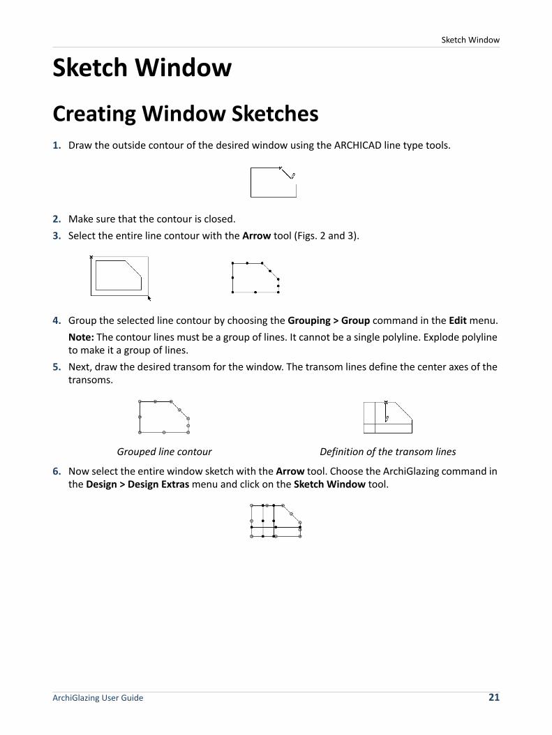
Sketch Window Creating Window Sketches1. Draw the outside contour of the desired window using the ARCHICAD line type tools.
2. Make sure that the contour is closed.3. Select the entire line contour with the Arrow tool (Figs. 2 and 3).
4. Group the selected line contour by choosing the Grouping > Group command in the Edit menu.Note: The contour lines must be a group of lines. It cannot be a single polyline. Explode polyline to make it a group of lines.
5. Next, draw the desired transom for the window. The transom lines define the center axes of the transoms.
6. Now select the entire window sketch with the Arrow tool. Choose the ArchiGlazing command in the Design > Design Extras menu and click on the Sketch Window tool.
Grouped line contour Definition of the transom lines
ArchiGlazing User Guide 21

Sketch Window
7. In the Sketch Window dialog box, specify the remaining parameters for the desired window.
8. Under Save as, select the ARCHICAD object type (Object, Window or Door) and the folder location and choose a name for the new window.
9. On completion of your entries, confirm them with OK.
10. From the ARCHICAD toolbar, select the object type created (Object, Window or Door), and click to position the new window.Note: The choice you make here affects the behavior of the structure. Window and Door type elements can only be placed into walls and will create an opening there. Object type elements can be placed independently, they do not create an opening in a wall, will be listed as objects (and not as windows or doors) in calculations and can only be opened with the Object tool.
Door and Window Frames, Sills and Ledges
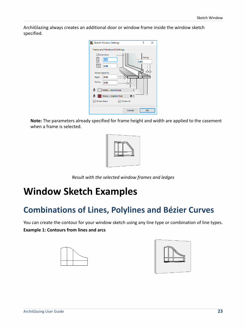
Under Options, specify the parameters for an additional door or window frame or window sill or ledge. Your settings will, however, only be used if Use Extra Frame and Windowsill Settings is selected. Window sills can only be generated for windows with a bottom edge.
Positioning Result in the floor plan Result in 3D
ArchiGlazing User Guide 22
Sketch Window
ArchiGlazing always creates an additional door or window frame inside the window sketch specified.
Note: The parameters already specified for frame height and width are applied to the casement when a frame is selected.
Result with the selected window frames and ledges
Window Sketch ExamplesCombinations of Lines, Polylines and Bézier CurvesYou can create the contour for your window sketch using any line type or combination of line types.Example 1: Contours from lines and arcs
ArchiGlazing User Guide 23

Sketch Window
The transom lines for the window sketches can also have any form or direction.Example 2: Slanted transom lines and a spline
Window Sketches from Circles and Ellipses ArchiGlazing cannot automatically recognize sketch contours created from geometrically closed contours (circle or ellipse). Specify a closed circular or elliptical window by using two semi-circles or semi-ellipses, and then group the elements. Example:
Window sketch Result in 3D
Window sketch Result in 3D
Window sketch Result in 3D
Window sketch Result in 3D
ArchiGlazing User Guide 24

Sketch Window
Window Sketch from SplinesIf you wish to use a spline to create a contour for an unusual window design, you must use two, grouped splines. Alternatively, you can use a single spline, then cut it into two parts and group them.Example:
Empty Wall OpeningsIf you select Empty Wall Opening, only an empty wall aperture will be created. If your window sketch contains transom lines, these will be ignored. Remember that the contour must be grouped before creating the structure.
Example:
Corner Glass Structures from Window SketchesIf you add a hotspot to a vertical transom line in your window sketch, ArchiGlazing will interpret the marked line as a corner post.Select the window sketch (including hotspot) and both walls in which you want to have a corner window. Choose ArchiGlazing and click the Sketch Window tool. In the appearing dialog box, specify the remaining parameters for the window in the usual way and confirm your entries with OK.
Window sketch Result in 3D
Window sketch Result in 3D
ArchiGlazing User Guide 25

Sketch Window
The corner glass structure will automatically be positioned at the corner of the wall.
Example: Mirrored line drawing as initial sketch
Frame Additions Connected to GroovesIf you wish to position the window in the floor plan with reveals, you can increase the size of the window frame at the side by the width of the reveal. With this you ensure that the overall size of the aperture of the window created corresponds to the line contour specified by you.
In the Reveal Setup dialog box you can define whether the reveal should increase the window frame width or should reduce the aperture of the window.
Note: Side frame additions are only possible with rectangular windows.
Selection of the window sketch incl. hotspot and corner of the wall Result in 3D
ArchiGlazing User Guide 26

Sketch Window
Subsequent Changes to Sketch WindowsSelect the glass structure in your project and open ArchiGlazing from the Design > Design Extras menu. Change the material settings for the profiles and glass surfaces and then click OK. The window will be updated automatically.If you pass your project as an archive document to another ARCHICAD user without an ArchiGlazing, the window can be opened and modified using ARCHICAD’s Window tool.
Note: The contour and transom layout cannot be subsequently modified in this dialog box. If you need to change them, you will have to create a new sketch window.
Saving a Sketch Window as a DoorIf you selected the Door object type in the Sketch Window Settings dialog box when saving your new structure, you will need to activate ARCHICAD's Door tool before positioning the door.ArchiGlazing will not automatically show a door leaf in the floor plan.You can, however, select the glass structure created in the floor plan and choose the Open object command from the File > Libraries and Objects menu. The Door Settings dialog box will then appear and you will be able to edit the 2D Symbol.
See also: the relevant section of the ARCHICAD Reference Guide.
Saving a Sketch Window as an ObjectIf you selected the Object type in the Sketch Window Settings dialog box when saving your new structure, you will need to activate ARCHICAD's Object tool before positioning the window.When a corner glass structure is saved as an object, the glass structure is not automatically positioned in the floor plan: ArchiGlazing creates two objects that you can position one after the other using ARCHICAD's Object tool.Select the Object tool and position the first half of the glass structure in the floor plan. Then open the Object Settings dialog box, select the second half of the glass structure and position this likewise in the floor plan.
ArchiGlazing User Guide 27

Conic Glass Structures
Conic Glass StructuresIn contrast to some of the other ArchiGlazing tools, no new library parts are created when dealing with conic glass structures. Instead, an object already stored in the library (“AG cone.GSM”) is automatically edited and positioned by ArchiGlazing according to its floor plan and division specifications.
Note: This structure is an ARCHICAD Library Part of Object type and will behave as such. It does not create an opening in a wall, will be listed as an object (and not as a window) in calculations and can only be opened with the Object tool.
Conic Glass Structures on Arcs and CirclesDraw a circle or arc in the ARCHICAD floor plan and select it. Choose the ArchiGlazing command in the Design > Design Extras menu and click the tool for conic glass structures. The Cone Glass Structure Settings dialog box will appear.
Specify the remaining parameters for the glass structure in the dialog box and confirm your choices with OK. The conic glass structure will automatically be positioned in the floor plan over the circle or arc.Example: Conic glass structure on an arc
Selection in the floor plan Result in the floor plan Result in 3D
ArchiGlazing User Guide 28

Conic Glass Structures
Conic Glass Structure over a Ceiling ApertureSelect a circular ceiling aperture in your ARCHICAD project and choose the ArchiGlazing command in the Design > Design Extras menu. Specify the remaining parameters for the glass structure in the Conic Glass Structure Settings dialog box and confirm your choices with OK. The corner glass structure will automatically be positioned over the ceiling aperture. In this way, the ceiling aperture corresponds to the overall (inner) diameter of the conic glass structure.
Note: Make sure to select ONLY the hole, not the whole slab to use this function.Example: Conic glass structure over a ceiling aperture
Conic Glass Structure over a Circular Wall or Wall ArcAfter selecting a circular or curved wall and specifying the conic glass structure parameters, ArchiGlazing positions the glass structure automatically to correspond to the wall course. The inner radius of the curved wall corresponds to the overall (inner) radius of the conic glass structure.Example: Conic glass structure over a wall arc
Selection in the floor plan Result in the floor plan Result in 3D
Selection in the floor plan Result in the floor plan Result in 3D
ArchiGlazing User Guide 29

Conic Glass Structures
Modifying Placed Conic Glass StructuresSelect the glass structure already positioned in your project. Click the Object tool in the ARCHICAD toolbar. In the Object Settings dialog box, you can change any of the parameters for the conic glass structure.
Note: Since the “AG cone.GSM” conic glass structure is a freestanding, fully parametrizable object, you can also open it without ArchiGlazing in ARCHICAD's Object Settings dialog box and position it manually in your project.
ArchiGlazing User Guide 30

Shed Glass Structures
Shed Glass StructuresIn contrast to some of the other ArchiGlazing tools, no new library parts are created when dealing with shed glass structures. Instead, an object already stored in the library (“AG shed.GSM”) is automatically edited and positioned by ArchiGlazing according to its floor plan and division specifications.
Note: This structure is an ARCHICAD Library Part of Object type and will behave as such. It does not create an opening in a wall, it will be listed as an object (and not as a window) in calculations, and can only be opened with the Object tool.
Shed Glass Structures on LinesDraw a rectangular closed line contour in the ARCHICAD floor plan and select it.Choose the ArchiGlazing command in the Design menu and click the tool for shed glass structures. The Shed Window Settings dialog box will appear.
Specify the remaining parameters for the glass structure in the dialog box and confirm your choices with OK. The shed glass structure will automatically be positioned over the rectangular contour in the floor plan.Example: Shed glass structure over a rectangular contour
Selection in the floor plan Result in the floor plan Result in 3D
ArchiGlazing User Guide 31

Shed Glass Structures
Shed Glass Structure over a Ceiling ApertureSelect a rectangular ceiling aperture in your ARCHICAD project and choose the ArchiGlazing command in the Design menu. Specify the remaining parameters for the glass structure in the Shed Glass Structure Settings dialog box and confirm your choices with OK. The shed glass structure will automatically be positioned over the ceiling aperture. In this way, the ceiling aperture corresponds to the overall (inner) diameter of the shed glass structure.
Note: Make sure to select ONLY the hole, not the whole slab to use this function.Example: Shed glass structure over a ceiling aperture
Shed Glass Structure over Rectangular Walls After selecting four rectangular walls and specifying the shed glass structure parameters, ArchiGlazing will automatically position the glass structure on the walls. The inner contour of the walls corresponds to the overall (inner) aperture of the shed glass structure.Example: Shed glass structure over a rectangular wall position
Shed Glass Structures with Differing Gable Types
In ArchiGlazing's Shed Window Settings dialog box, you can choose from among six types for the glass structure gable surfaces. The chosen type is always used on both gables.
Selection in the floor plan Result in the floor plan Result in 3D
Selection in the floor plan Result in the floor plan Result in 3D
ArchiGlazing User Guide 32

Shed Glass Structures
Example: Different gables for type: saddle/barreled
Note: When choosing the gable type, bear in mind that you will get unwanted results if the transoms are set too wide.
Shed Roof TypesUsing the Shed type button in the Shed Window Settings dialog box, you can control whether you wish to design a saddle or barrel shape.While the height of the saddle shed can be controlled by either the roof inclination or the given height, the height of the barrel shed is only defined by the crown height.
If you switch from the saddle type to the barrel type, all the settings made so far for division, materials, transom cross sections, line type, etc., will be transferred to the new shed type.The number of vertical fields are applied separately to both sides of the roof in the case of the saddle type, whereas with the barrel type they are distributed over the entire cross section.
Simple Vertical transoms
1 vertical transom Closed
Star transoms Open
ArchiGlazing User Guide 33

Shed Glass Structures
Example: Specification of four vertical fields
Modifying Placed Shed Glass StructuresNote: Since the “AG shed.GSM” shed glass structure is a freestanding, fully parametrizable object, you can also open it without ArchiGlazing in ARCHICAD's Object Settings dialog box and position it manually in your project.
Result with saddle type shed Result with barrel type shed
ArchiGlazing User Guide 34

Winter Gardens
Winter GardensIn contrast to some of the other ArchiGlazing tools, no new library parts are created when dealing with winter gardens. Instead, an object already stored in the library (“AG Winter Garden.GSM”) is automatically edited and positioned by ArchiGlazing according to its floor plan and division/distribution specifications.
Note: This structure is an ARCHICAD Library Part of Object type and will behave as such. It does not create an opening in a wall, it will be listed as an object (and not as a window) in calculations, and can only be opened with the Object tool.
Winter Garden from Three LinesDraw the outside contour of the winter garden in the ARCHICAD floor plan using the Line tool: one front line and, at a right angle to this, two side lines of equal length.Choose the ArchiGlazing command in the Design menu and click the tool for winter gardens. The Winter Garden Settings dialog box will appear.
Note: If the two side lines are of different length, the length of the line which was first drawn will be taken into consideration.
Specify the remaining parameters for the glass structure in the dialog box and confirm your choices with OK. The winter garden will automatically be positioned within the line contour.
p
ArchiGlazing User Guide 35

Winter Gardens
Example: Winter Garden from three lines in floor plan
Winter Garden from Two LinesArchiGlazing will only create the glass facades for the winter garden along your lines. Consequently, you have the option to create two- or three-sided open winter gardens by omitting side lines. If less than three baselines are specified, you must then inform ArchiGlazing where you wish the top ridge (highest point) of the winter garden to be by means of a hotspot.Example 1: Winter Garden from two lines with (spot height) hotspot
Example 2: The same line specifications but with a displaced hotspot
Winter Garden from a (Front) LineIf you specify only one line in the floor plan, ArchiGlazing will always interpret this as the front line of the winter garden. To mark the position of the top ridge - and therefore also the (building) depth - of the winter garden, add another hotspot in the free area.
Selection in the floor plan Result in the floor plan Result in 3D
Selection in the floor plan Result in the floor plan Result in 3D
Selection in the floor plan Result in the floor plan Result in 3D
ArchiGlazing User Guide 36

Winter Gardens
Example: Winter Garden from line and hotspot
Note: If the Hotspot is not placed at the end of the line chain, the front side of the wintergarten will adjust to the line that was drawn first. The other line gives the sidewall, and the position of the hotspot is not taken into consideration.
Winter Garden from Lines and WallsFor easier creation of winter gardens attached to walls, adjacent walls can also be included in the selection.Example: Winter Garden from lines and wall
If only one wall is selected that is parallel to one line, ArchiGlazing interprets the line as the front of the winter garden. The distance between the line and the wall defines the building depth.Example: Winter Garden from one line and a wall
If you wish to create a winter garden glass structure between two parallel walls, in addition to the front line, you must mark the position of the top ridge (building depth) with a hotspot.
Selection in the floor plan Result in the floor plan Result in 3D
Selection in the floor plan Result in the floor plan Result in 3D
Selection in the floor Result in the floor plan Result in 3D
ArchiGlazing User Guide 37

Winter Gardens
Example: Winter Garden between two walls
Note: It is a basic rule that in winter garden designs, lines and walls must be parallel or perpendicular to one another.
If you wish to create a winter garden glass structure in a wall recess, you do not need to mark the position of the top ridge with a hotspot. ArchiGlazing will automatically position the top ridge on the wall running parallel to the front line.Example: Winter Garden in a wall recess
With a winter garden glass structure in wall corners, the position of the hotspot determines the orientation of the winter garden.Example 1: Winter Garden in a wall corner
Example 2: Winter Garden in a wall corner with a displaced hotspot
Selection in the floor Result in the floor plan Result in 3D
Selection in the floor Result in the floor plan Result in 3D
Selection in the floor Result in the floor plan Result in 3D
Selection in the floor Result in the floor plan Result in 3D
Hotspot
ArchiGlazing User Guide 38
Winter Gardens
Changing the Roof Pitch of a Winter GardenArchiGlazing calculates the top ridge height of the winter garden using the building depth specified by you along with the default settings for eaves (1.80 m) and roof pitch (30°). The top ridge height calculated is displayed in the Winter Garden settings dialog.If you change the winter garden settings, the following will happen to the parameters:• Change top ridge height: The roof pitch will be automatically corrected, the eaves height will
remain unchanged.• Change eaves height: The roof pitch will automatically be corrected, the top ridge height will
remain unchanged.• Change roof pitch: The top ridge height will be automatically corrected, the eaves height will
remain unchanged.
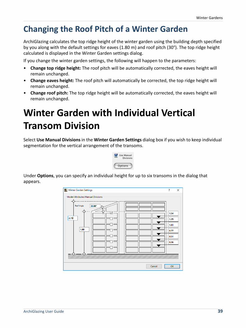
Winter Garden with Individual Vertical Transom DivisionSelect Use Manual Divisions in the Winter Garden Settings dialog box if you wish to keep individual segmentation for the vertical arrangement of the transoms.
Under Options, you can specify an individual height for up to six transoms in the dialog that appears.
ArchiGlazing User Guide 39

Winter Gardens
Controlling the Roof Profile of a Winter GardenArchiGlazing always adopts the number of horizontal fields the user specified from the front and side surfaces and integrates it into the roof area of the winter garden. It even does so when no side areas have been created. Set the number of horizontal side fields to one if you want a roof area without vertical partitioning.
Modifying placed Winter GardensNote: Since the “AG Winter Garden.GSM” winter garden is a freestanding, fully parametrizable object, you can also open it without ArchiGlazing in ARCHICAD's Object Settings dialog box and position it manually in your project.
ArchiGlazing User Guide 40


