54
Architecting & Designing Air Transportation Systems Prof. John-Paul Clarke Massachusetts Institute of Technology 16.899 March 4, 2004
Architecting & Designing Air Transportation Systems
Prof. John-Paul ClarkeMassachusetts Institute of Technology
16.899March 4, 2004
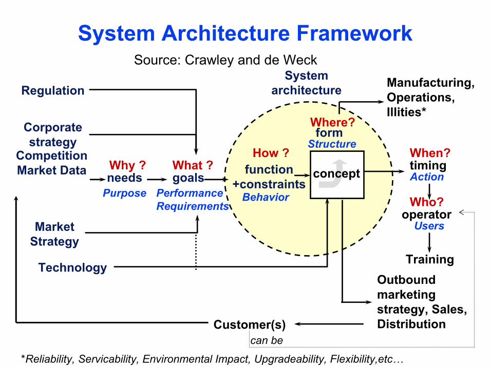
Regulation
Corporatestrategy
CompetitionMarket Data
MarketStrategy
Technology
Systemarchitecture
needs goals function+constraints
form
timing
operator
TrainingOutbound marketing strategy, Sales, Distribution
Manufacturing, Operations,Illities*
Why ?
Purpose
What ?
PerformanceRequirements
How ?
Behavior
Where?Structure
When?
Action
Who?
Users
Customer(s)can be
concept
System Architecture FrameworkSource: Crawley and de Weck
*Reliability, Servicability, Environmental Impact, Upgradeability, Flexibility,etc…
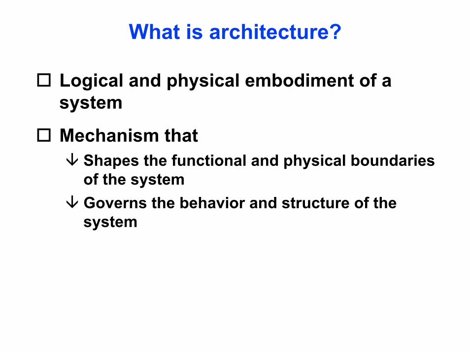
What is architecture?
Logical and physical embodiment of a system
Mechanism that Shapes the functional and physical boundaries of the systemGoverns the behavior and structure of the system
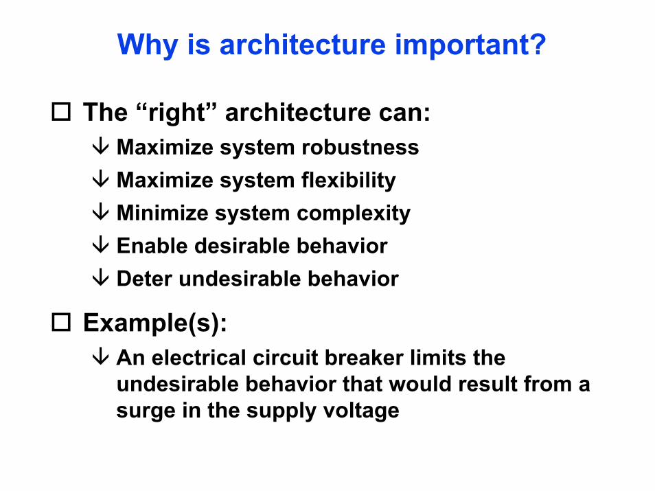
Why is architecture important?
The “right” architecture can:Maximize system robustnessMaximize system flexibilityMinimize system complexityEnable desirable behaviorDeter undesirable behavior
Example(s): An electrical circuit breaker limits the undesirable behavior that would result from a surge in the supply voltage
How do we determine architecture?
Synthesis
Discovery
Chance
Synthesis
Combining existing systems to satisfy stated needs
Requires logic and complete (or near complete) knowledge of existing systems
Example(s): Designing a mechanism to support a person who wants to cross “over” a river or stream
Key question(s) for synthesis?
What functions do I need to get the job done?
Is there a way to combine existing systems to do the desired functions without having too many extra functions and too much extra form?
What rules do I have to apply to do this?
Discovery
Using knowledge of existing architecture to “discover” new architecture
Requires knowledge of existing systems and pattern recognition, analysis and abstraction skills
Example(s):Man learning how to flyDisease and drug pathways
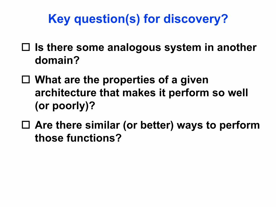
Key question(s) for discovery?
Is there some analogous system in another domain?
What are the properties of a given architecture that makes it perform so well (or poorly)?
Are there similar (or better) ways to perform those functions?
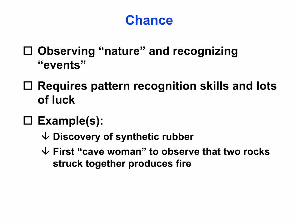
Chance
Observing “nature” and recognizing “events”
Requires pattern recognition skills and lots of luck
Example(s):Discovery of synthetic rubberFirst “cave woman” to observe that two rocks struck together produces fire
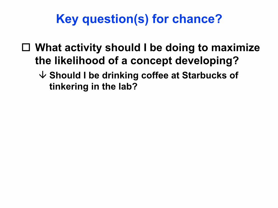
Key question(s) for chance?
What activity should I be doing to maximize the likelihood of a concept developing?
Should I be drinking coffee at Starbucks of tinkering in the lab?
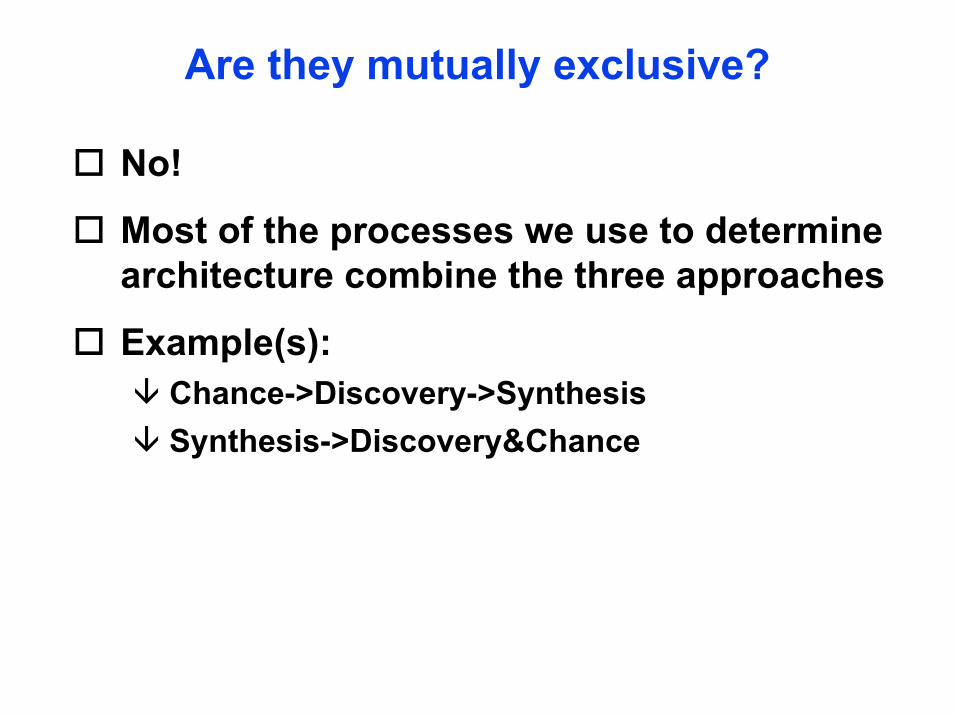
Are they mutually exclusive?
No!
Most of the processes we use to determine architecture combine the three approaches
Example(s):Chance->Discovery->SynthesisSynthesis->Discovery&Chance

How do I know the best architecture?
Selection processNatural selectionArtificial selection
Goals and metrics

Robustness
Ability of a system to “perform” under various operating conditions
Robustness can be measuredRange of operating conditions (both internal and external) over which the performance of a system is within an acceptable “distance” of its peak performanceEx: Frequency response of a control system
Flexibility
Flexibility is the means though which we achieve robustness
Flexibility can be measuredNumber of different modes or states in which system can be successfully operatedEase with which the operating mode or state can be changed
Ex: Humans
Flexibility leads to complexity
Complexity
Complexity is the degree to which the set of possible states of a system exceeds the set of desired states
Complexity can be measuredInformation required to describe all the components, their interconnections and their interactionsNumber of homogeneous/dissimilar elements, homogeneous/dissimilar interconnections, and ways components are organized
Complexity
Complexity is subjectiveInfluenced by user perception and presentation schemeEx: cruise control system in automobiles
• Low apparent complexity as presented to drivers: knobs, buttons
• High apparent complexity if you include physical parts such as electromechanical components or logics such as control laws
Complexity
Complexity can be decomposedEssential complexity: minimum level of complexity that is essential to deliver system functionGratuitous complexity: additional complexity beyond essential complexity
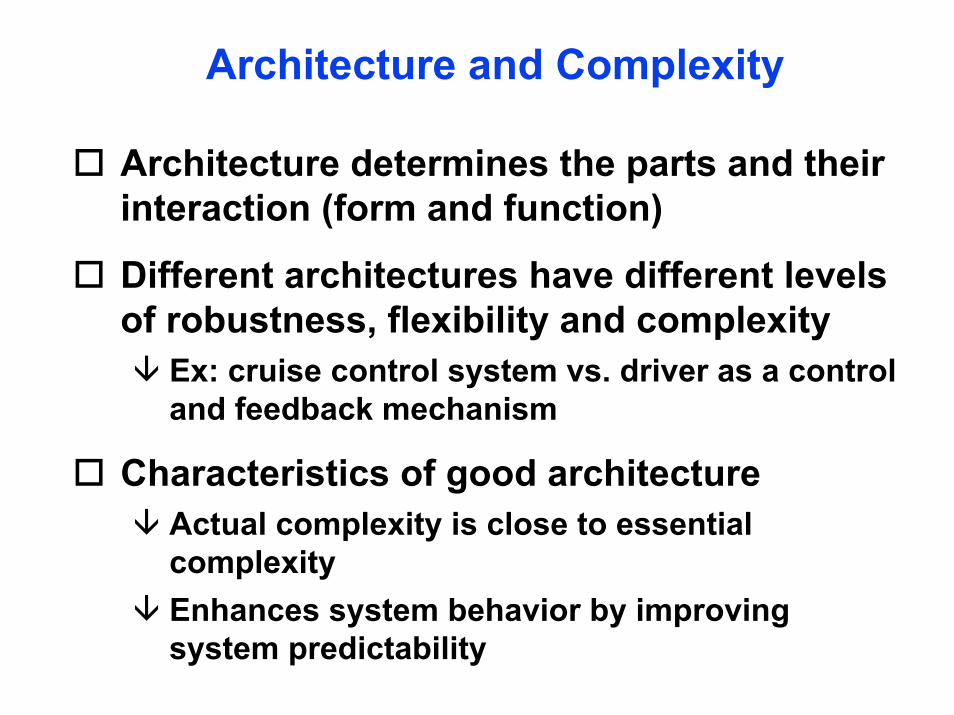
Architecture and Complexity
Architecture determines the parts and their interaction (form and function)
Different architectures have different levels of robustness, flexibility and complexity
Ex: cruise control system vs. driver as a control and feedback mechanism
Characteristics of good architectureActual complexity is close to essential complexityEnhances system behavior by improving system predictability
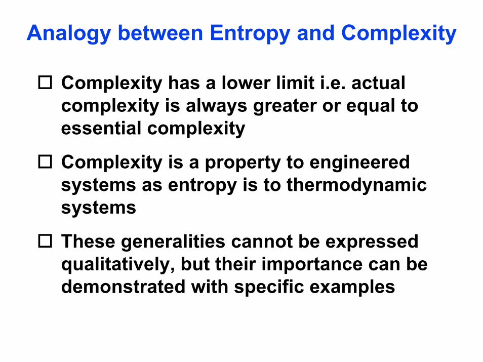
Analogy between Entropy and Complexity
Complexity has a lower limit i.e. actual complexity is always greater or equal to essential complexity
Complexity is a property to engineered systems as entropy is to thermodynamic systems
These generalities cannot be expressed qualitatively, but their importance can be demonstrated with specific examples
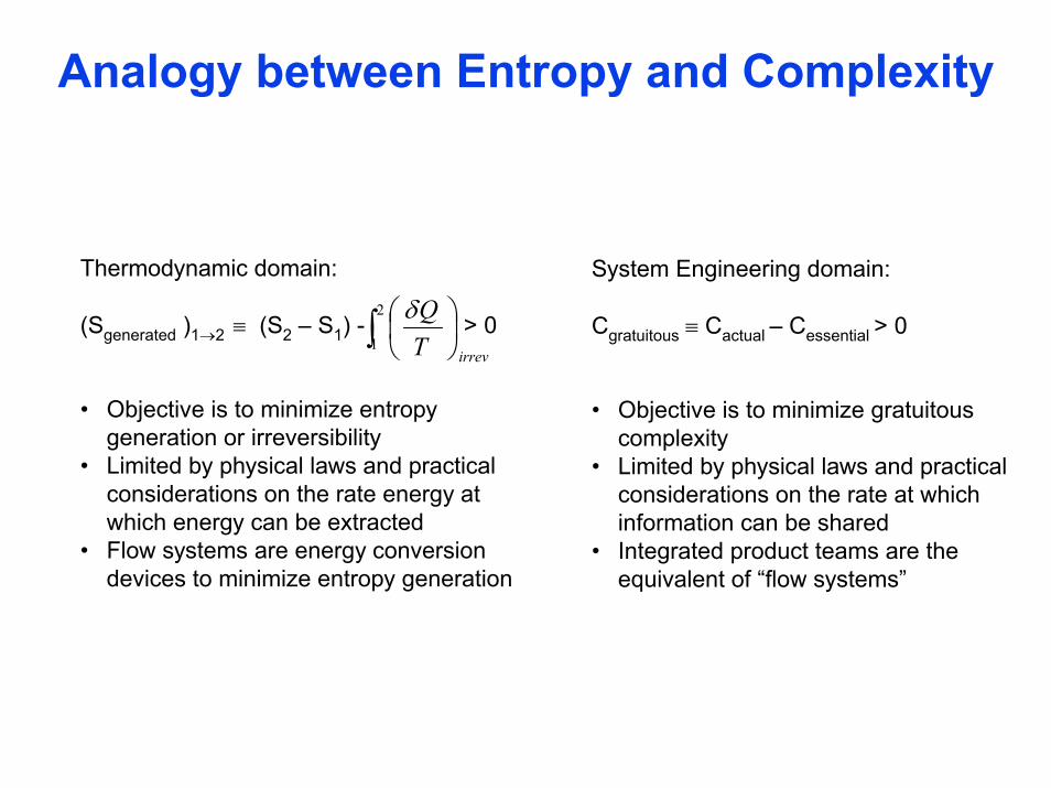
Analogy between Entropy and Complexity
Thermodynamic domain:
(Sgenerated )1→2 ≡ (S2 – S1) - > 0
• Objective is to minimize entropy generation or irreversibility
• Limited by physical laws and practical considerations on the rate energy at which energy can be extracted
• Flow systems are energy conversion devices to minimize entropy generation
System Engineering domain:
Cgratuitous ≡ Cactual – Cessential > 0
• Objective is to minimize gratuitous complexity
• Limited by physical laws and practical considerations on the rate at which information can be shared
• Integrated product teams are the equivalent of “flow systems”
∫ ⎟⎠⎞
⎜⎝⎛2
1irrevT
Qδ
Examples Problem
How can we reduce the noise impact of aircraft (during approach) on communities near airports without losing capacity?
Motivation
Noise is an important factor in the siting and operation of airports
Negative reaction by community to noise from aircraftCommunity agreement required for increase in number of operations, airport expansion or airspace changesLengthy environmental studies required for approval and federal mitigation fundingSignificant reduction in number of new runways built

Motivation (2)
120
110
100
90
CV990ACV880-22720
707-100
B-52
BAC-111
Normalized to 100,000 Ib thrustNoise level are for airplane/engine configurations at time of initial service
DC9-10
DC8-20
DC8-61 737-100
727-200
747-300A310-300767-200
757-200737-300
767-300
L-1011
Year of Initial Service
Noi
se L
evel
(EPN
dB)
(150
0 ft
Side
line)
747-400737-500
A321
A330
A340737-700
777
A320-100
MD-11
(est.)
727-100
707-300B
747-100
747-200A300B2-101
737-200
1950 1960 1970 1980 1990 1995
Second Generation TurbofanMD-80
737-400
MD90-30BAe-146-200
DC10-10
Caravelle
Comet 4
DC10-30
First Generation Turbofan
Turbojet
Motivation (4)
Operational procedures can provide significant additional noise reductions
Thrust management strategies redistribute noise impact during departure and reduce impact during approach Lateral deviations direct aircraft away from populated areas during departure and approachApplied only at airports with severe noise restrictionsLimited in applications because of flight guidance technology limitations
Motivation (4)
Advanced flight guidance technologies may be used to improve the applicability and effectiveness of noise abatement procedures
GPS will be the base of the future primary navigation system in the United States [FAA, 1996]Flight procedures are being re-examined as part of the transition to satellite navigationArea Navigation (RNAV) using position information from the Global Positioning System (GPS) enables flexible trajectories
Background
Noise impact determined by 3 componentsSource Characteristics
• Intensity, frequency content, & directivityPath Characteristics
• Attenuation, diffractionReceiver Characteristics
• Population distribution, time of day
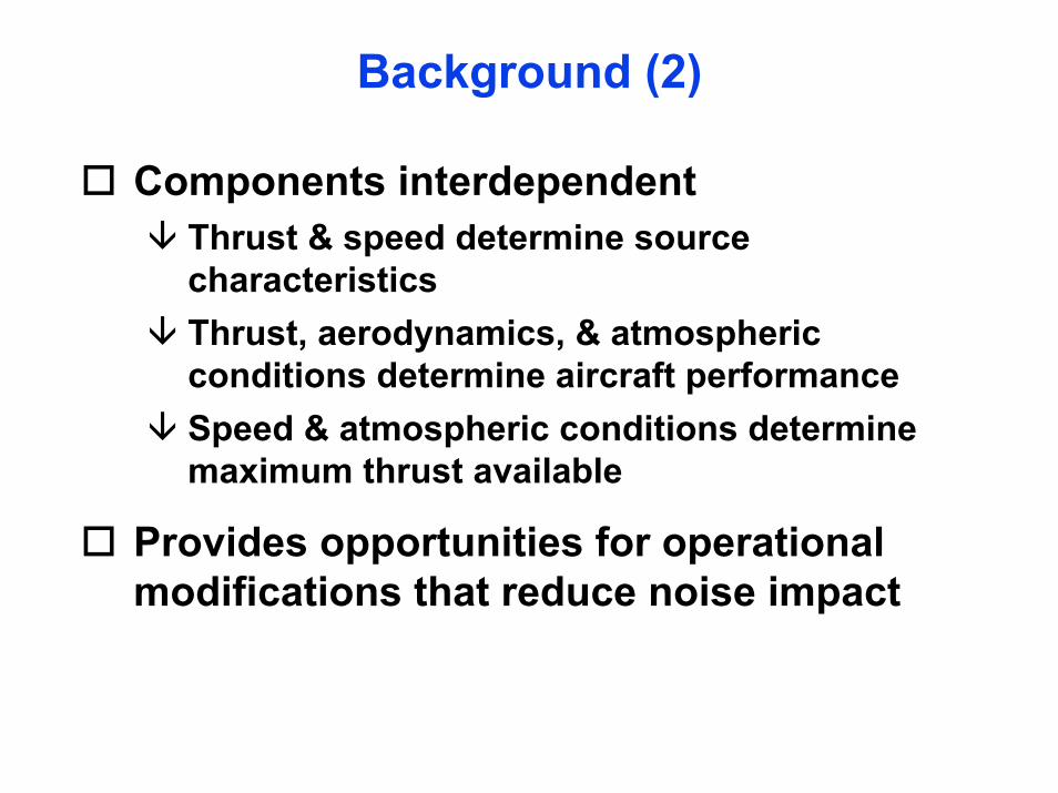
Background (2)
Components interdependentThrust & speed determine source characteristicsThrust, aerodynamics, & atmospheric conditions determine aircraft performanceSpeed & atmospheric conditions determine maximum thrust available
Provides opportunities for operational modifications that reduce noise impact

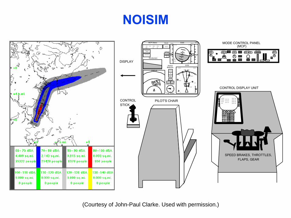
NOISIM
Methodology for developing noise abatement procedures
Combines Flight Simulator, Noise Model, and Geographic Information System (GIS)
Simulates realistic aircraft operation (737-200 & 767-300)
Evaluates critical components simultaneously
Rapid prototyping and evaluation of noise abatement procedures
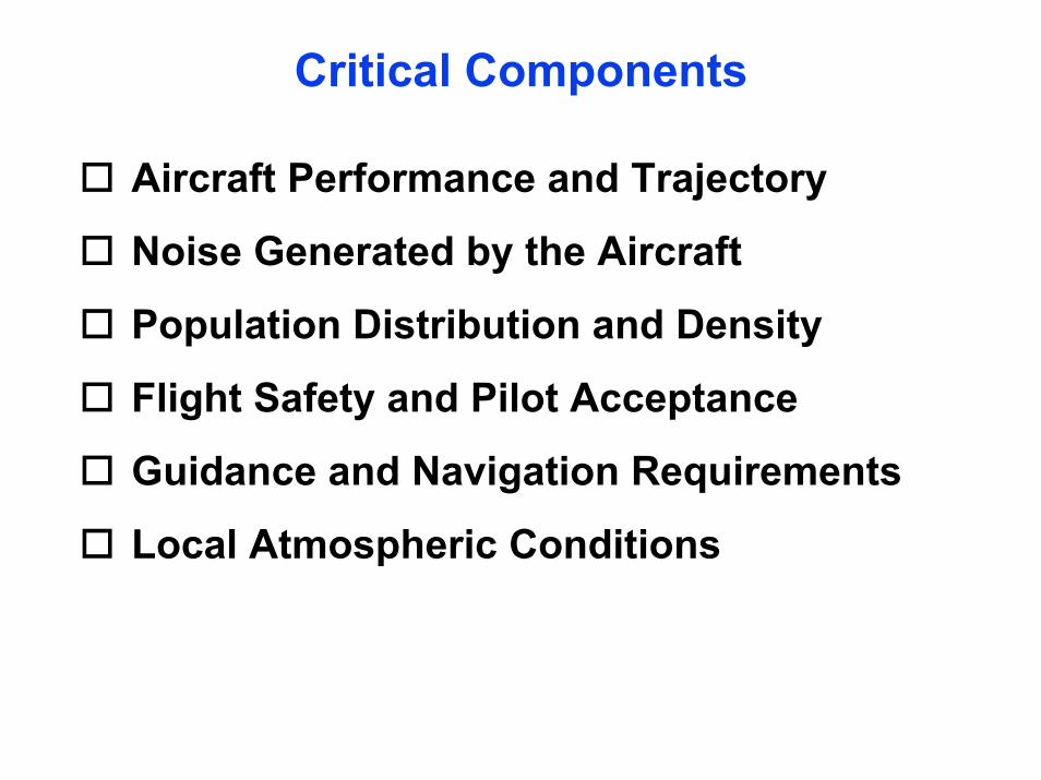
Critical Components
Aircraft Performance and Trajectory
Noise Generated by the Aircraft
Population Distribution and Density
Flight Safety and Pilot Acceptance
Guidance and Navigation Requirements
Local Atmospheric Conditions
NOISIMMODE CONTROL PANEL
(MCP)COURSE IAS/MACH HEADING VERT SPEED COURSE ALTITUDE
3
6
10
17
FCS
TRK M
8.9 NM 0623.7z
KCOS
CAGER
WENNY
FLOTS
EHSI
0619.6z
ClockMCP Status
ALT V/S HDG SPD
5000 016 180
NOSE
LEFT RIGHT
Gear Status
Flap Status
UP
15
15
20
2530
Marker Beacons
EADISpeed Altitude
PULL UP
GND
PROX
MID
INNER
OUTER 030
36
GPWS
Windscreen
5300185
A/T IDLE VNAV
CMD
LNAV
GS 193 2470
-200
Vertical Speed
PRECIP
WINDSHEAR
WINDSHEARAHEAD
CONTROL DISPLAY UNIT
CAGER WENNY WATKI EKR
036 / 16.9 060 / 23.5 076 / 17.4
35000 / 350 30000 / 300 25000 / 250 20000 / 250
SPEED BRAKES, THROTTLES, FLAPS, GEAR
PILOT'S CHAIRCONTROL STICK
DISPLAY
(Courtesy of John-Paul Clarke. Used with permission.)
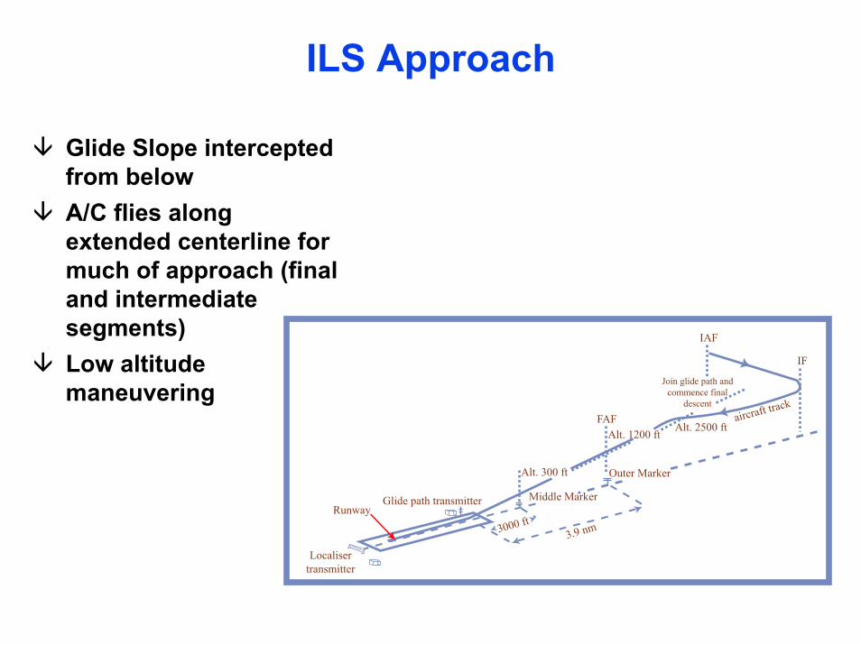
ILS Approach
Glide Slope intercepted from belowA/C flies along extended centerline for much of approach (final and intermediate segments)Low altitude maneuvering
Localisertransmitter
Runway
Alt. 300 ft
Alt. 1200 ft
Join glide path andcommence final
descent
Outer Marker
Middle Marker
3.9 nm3000 ft
Alt. 2500 ft
IF
IAF
FAF aircraft track
Glide path transmitter

ILS Approach (JFK 13L)Approach Chart Noise Impact
(Image removed due to copyright considerations.)
(Courtesy of John-Paul Clarke. Used with permission.)
3° Decelerating Approach
Single segmentAircraft intercepts segment at high alt. & speedAircraft decelerates during descent at idle thrustAchieves approach speed at 500-1,000 ft AGLDoes not require additional displays
(Image removed due to copyright considerations.)
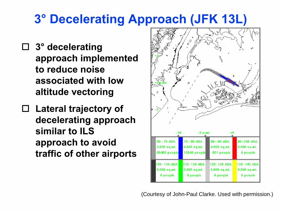
3° Decelerating Approach (JFK 13L)
3° decelerating approach implemented to reduce noise associated with low altitude vectoring
Lateral trajectory of decelerating approach similar to ILS approach to avoid traffic of other airports
(Courtesy of John-Paul Clarke. Used with permission.)
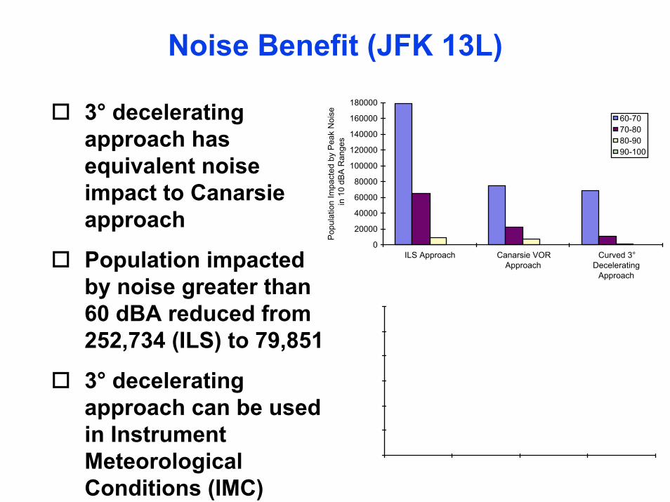
Noise Benefit (JFK 13L)
3° decelerating approach has equivalent noise impact to Canarsie approach
Population impacted by noise greater than 60 dBA reduced from 252,734 (ILS) to 79,851
3° decelerating approach can be used in Instrument Meteorological Conditions (IMC)
0
20000
40000
60000
80000
100000
120000
140000
160000
180000
ILS Approach Canarsie VORApproach
Curved 3°Decelerating
Approach
Pop
ulat
ion
Impa
cted
by
Pea
k N
oise
in 1
0 dB
A R
ange
s
60-7070-8080-9090-100
0
50000
100000
150000
200000
250000
300000
60 70 80 90 100
Peak Noise (dBA)
ILS Approach
Canarsie VORApproachCurved 3° DeceleratingApproach
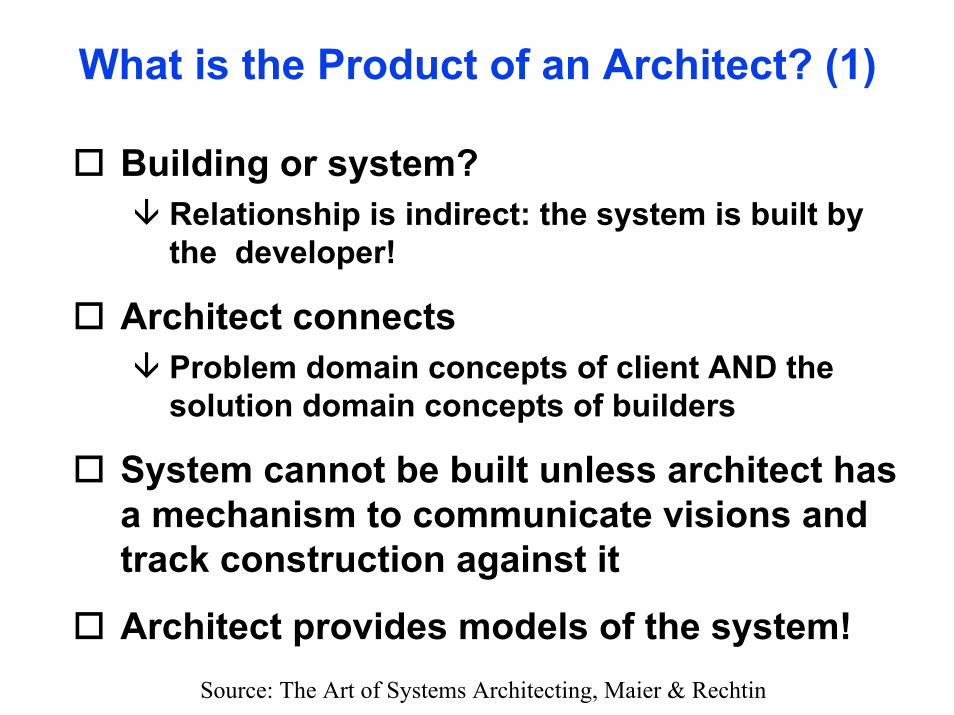
What is the Product of an Architect? (1)
Building or system?Relationship is indirect: the system is built by the developer!
Architect connectsProblem domain concepts of client AND the solution domain concepts of builders
System cannot be built unless architect has a mechanism to communicate visions and track construction against it
Architect provides models of the system!Source: The Art of Systems Architecting, Maier & Rechtin
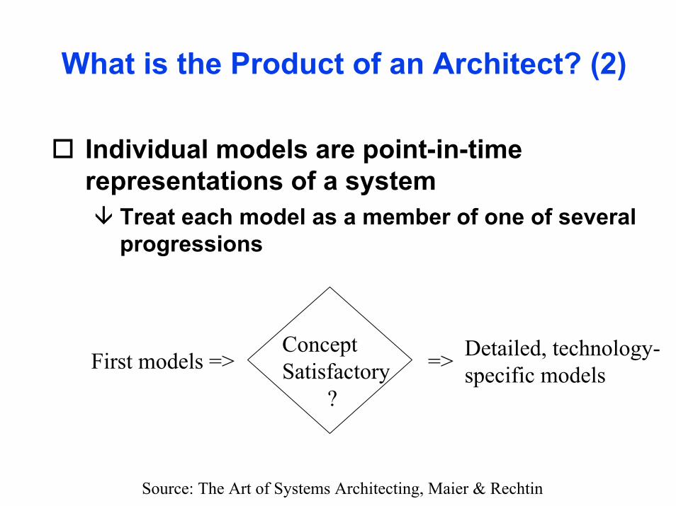
What is the Product of an Architect? (2)
Individual models are point-in-time representations of a system
Treat each model as a member of one of several progressions
ConceptSatisfactory
?
Detailed, technology-specific models=>First models =>
Source: The Art of Systems Architecting, Maier & Rechtin
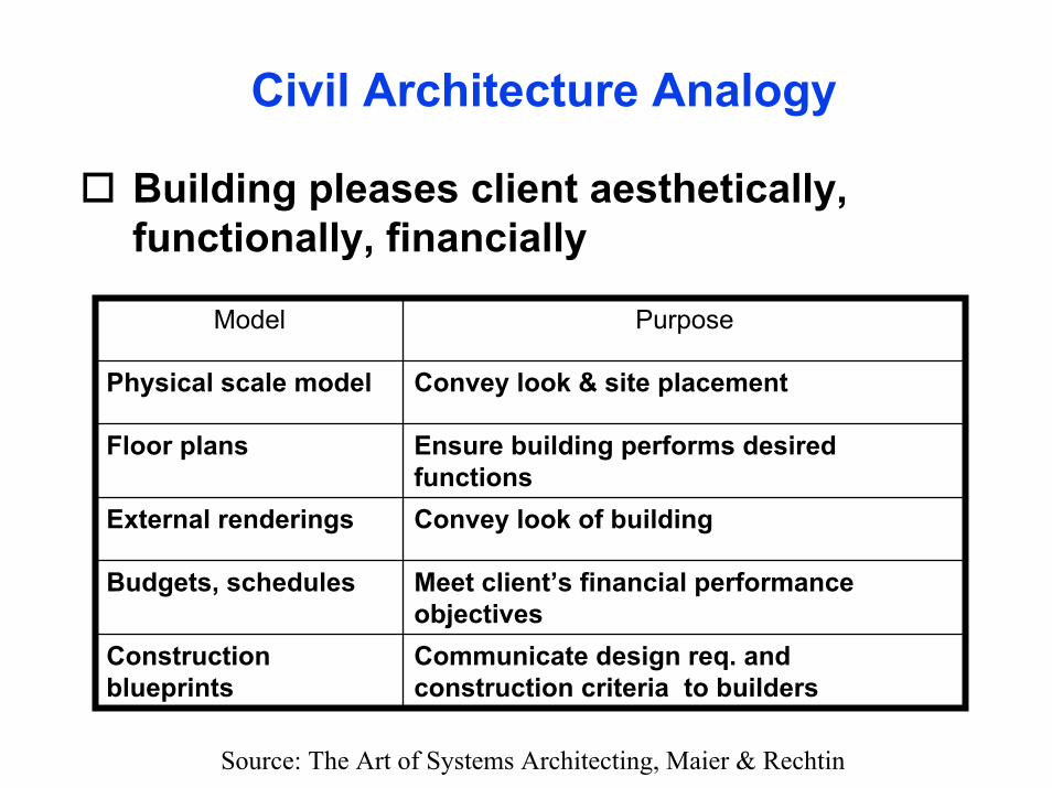
Civil Architecture Analogy
Building pleases client aesthetically, functionally, financially
Model Purpose
Physical scale model Convey look & site placement
Floor plans Ensure building performs desired functions
External renderings Convey look of building
Budgets, schedules Meet client’s financial performance objectives
Construction blueprints
Communicate design req. and construction criteria to builders
Source: The Art of Systems Architecting, Maier & Rechtin
Models
ModelsMeans of communication with clients, builders, and usersLanguage of architectImportant for constructing system and describing and diagnosing its operationCan be classified by their roles or content
Source: The Art of Systems Architecting, Maier & Rechtin

Models (2)
Terminology (IEEE standard):Model: approximation, representation, or idealization of … a real-world system.View: representation of a system from the perspective of related concerns or issuesViewpoint: template, pattern, or specification for constructing a view
Source: The Art of Systems Architecting, Maier & Rechtin
Models (3)
In other words:A Model is a representation of somethingA View is a collection of models that share the property that they are relevant to the same concerns for a system stakeholder.A Viewpoint is an abstraction of view across many systems.
Source: The Art of Systems Architecting, Maier & Rechtin
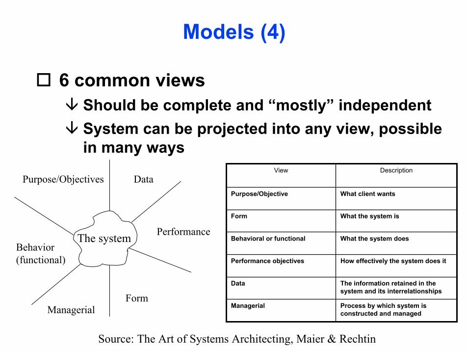
Models (4)
6 common viewsShould be complete and “mostly” independentSystem can be projected into any view, possible in many ways
PerformanceThe system
Purpose/Objectives Data
FormManagerial
Behavior(functional)
View Description
Purpose/Objective What client wants
Form What the system is
Behavioral or functional What the system does
Performance objectives How effectively the system does it
Data The information retained in the system and its interrelationships
Managerial Process by which system is constructed and managed
Source: The Art of Systems Architecting, Maier & Rechtin
Models (5)
Integrated modeling methodA system of representation that links multiple viewsConsists of a set of models for a subset of views and a set of rules or additional models to link the core viewsMost are domain specific
Source: The Art of Systems Architecting, Maier & Rechtin

Integrated Modeling Methodologies
Method Domain
Hatley/Pirbhai(H/P) Computer-based reactive or event-driven systems
Quantitative quality function deployment (Q2FD)
Systems with extensive quantitative performance objectives and understood performance models
Object modeling technique (OMT) Large-scale, date-intensive software systems, especially those implemented in modern object languages
ADARTS Large-scale, real-time software systems
Manufacturing system analysis (MSA) Intelligent manufacturing systems
Source: The Art of Systems Architecting, Maier & Rechtin

Integrated Modeling MethodologiesQuantitative QFD
Performance objectives are most important to the clientPerformance-centered approach to system specification, decomposition, and synthesisJapanese-originated method for visually organizing the decomposition of customer objectives
Source: The Art of Systems Architecting, Maier & Rechtin

Integrated Modeling Methodologies
Quantitative QFD-based approach:1. Identify a set of performance objectives of
interest to the client. Determine appropriate values or ranges for meeting these objectives through competitive analysis.
2. Identify the set of system-level design parameters that determine the performance for each objective. Determine satisfaction models that relate the parameters and objectives.
Source: The Art of Systems Architecting, Maier & Rechtin
Integrated Modeling Methodologies
Quantitative QFD-based approach:3. Determine the relationships of the parameters
and objectives, and the interrelationships among the parameters. Which affect which?
4. Set one or more values for each parameter. Multiple values may be set, for example, minimum, nominal, and target. Additional slots provide tracking form detailed design activities.
Source: The Art of Systems Architecting, Maier & Rechtin
Integrated Modeling Methodologies
Quantitative QFD-based approach:5. Repeat the process iteratively using the system
design parameters as objectives. At each stage the parameters at the next level up become the objectives at the next level down.
6. Continue the process of decomposition on as many level as desired. As detailed designs are developed, their parameter value can flow up the hierarchy to track estimated performance for customer objectives.
Source: The Art of Systems Architecting, Maier & Rechtin
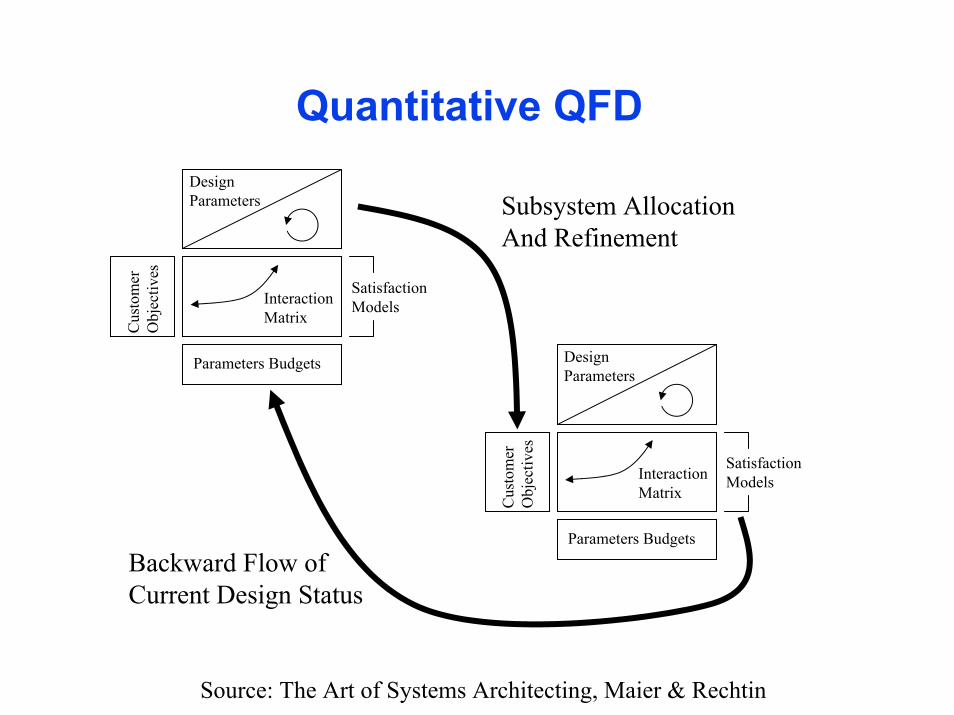
Quantitative QFDDesign Parameters
Interaction Matrix
Parameters Budgets
Cus
tom
er
Obj
ectiv
es
SatisfactionModels
Design Parameters
Interaction Matrix
Parameters Budgets
Cus
tom
er
Obj
ectiv
es
SatisfactionModels
Subsystem Allocation And Refinement
Backward Flow ofCurrent Design Status
Source: The Art of Systems Architecting, Maier & Rechtin
CDIO
Concept ViewCombination of Purpose and Form ViewsQuestion(s)
• What functions does the customer want? (now & in the future)
• What functions does the customer need? (now & in the future)

CDIO
Design ViewCombination of Behavior and Performance ViewsQuestion(s)
• What vehicles and systems do you think will fulfill these wants and needs?
• How would these vehicles and systems fit together?
• How well would the system perform?

CDIO
Implementation ViewCombination of Data and Management ViewsQuestion(s)
• How would you build the system?• What physical resources are required?• What financial resources are required?• What socio-political resources are required?
CDIO
Operations ViewCombination of Management View and the Business CaseQuestion(s)
• How would you operate the system?• What physical resources are required?• What financial resources are required?• What sociopolitical resources are required?• Will all stakeholders profit from this deal?


