Architectural Structures For Large Systems Design Position Paper for Workshop ‘Exploring Large Systems Issues’ at OOPSLA’97, Octo- ber 5 – 9, Atlanta, USA by Walter Kriha, Daniel Kesch, Stephan Pluess, and
Transcript
Architectural Structures For LargeSystems Design
Position Paper for Workshop ‘ExploringLarge Systems Issues’ at OOPSLA’97, Octo-
ber 5 – 9, Atlanta, USA
by Walter Kriha, Daniel Kesch, Stephan Pluess, and
Architectural Structures For Large Systems Design: Position Pa-per for Workshop ‘Exploring Large Systems Issues’ at OOP-SLA’97, October 5 – 9, Atlanta, USAby Walter Kriha, Daniel Kesch, Stephan Pluess, and
Published 23.09.97
Table of Contents..............................................................................................................................................1. Introduction .........................................................................................................................2. The Architectural Structures of A Large System .........................................................................
Architectural Structures: An Overview ................................................................................. 2Are the Architectural Structures Real? .................................................................................. 2Visualizing Architectural Structures and Their Dependencies ................................................... 3
Understanding the Diagram ........................................................................................ 3The Architectural Structures Dependency Diagram ......................................................... 3Example: How large-scale System Topics Depend On Connected Structures ....................... 5
3. Architectural Structures and The Software Development Process ...................................................4. Quantifying Design Quality Based on Architectural Structures ......................................................
Requirements ..................................................................................................................8The rating process ............................................................................................................ 8The formula .................................................................................................................... 9AnExample .................................................................................................................... 10
5.Conclusion ..........................................................................................................................6.Authors ...............................................................................................................................7. Appendix A: An Architectural Structures Catalog .......................................................................8. Appendix B: A Metrics Example .............................................................................................9. Appendix C: List of References ...............................................................................................
The design for a large software system must realize an architecture that is 1) sophisticated and compre-hensive, and 2) covers all aspects relating to its design, implementation, and evolvability. We argue that abetter understanding of the properties of OO system design is obtained by structuring its architecture.This can be done along several criterias: its logical abstractions; its physical inheritance relationships; itscompile-, link- and run-time dependencies; its generation and maintenance; its extendibility; and the or-ganization of its source code. These structures in part conflict with each other, for example, a logical in-heritance hierarchy can lead to long generation times and maintenance problems due to the resultingphysical couplings. In order to improve OO design quality, we seek to make transparent these softwarestructures, to explain their need to be considered early-on and continuously in the development process,to describe their impacts and upon each other, and to use these structures to rate an OO system design.The paper presents these software structures as a set of architectural structures to be considered when de-signing, implementing, and evolving a large system’s architecture in order to improve and challenge itsdesign.
vi
Chapter 1. IntroductionA large software project can span many developers, several layers of management, and sometimes even multiplegeographic sites and source code bases. The architecture of such a system will not only be reflected in the logi-cal structure of the application, but also be expressed in other underlying software structures that most often arein conflict with each other. A reason for the failure of a lot of software projects – even or especially object-ori-ented applications - lies in the disregard of these software structures and their interactions with each other.
More often than not, an application is specified after an initial analysis and design cycle, and then implementedaccordingly in a programming language such as C++. However, the development team usually realizes upon ex-ecution of the software that:
1. the resulting application is totally inflexible
2. it has excessively long compile-, link- and build-times
3. extensions usually result in a complete re-installation of the software
4. everything sort of depends on everything else, even though it might have been programmed object-oriented
5. the software is totally platform dependent
What does this mean? The logic of such an application may be right, but the software’s underlying architecturedid not realize the properties of a large system that one would consider appropriate:
1. plug-n-play-like functionality enhancements
2. logical (symbolic) interdependencies rather than physical ones
3. well-structured, well-defined "uses" hierarchies, where lower levels have no knowledge of higher ones
4. encapsulation of platform dependencies
Thus good architectural design has a major impact on the success of a software system. On the other hand, asoftware architecture is invisible, implicit, and often hard to visualize. As an emerging discipline, there is agrowing body of work addressing the codification of architectural expertise. For example, Kruchten’s 4+1 Viewarchitecture model [1] seeks to describe a software architecture as a model composed of up to four views or di-mensions.
We motivate the intention behind the set of architectural structures presented in this paper as 1) a pragmatic en-hancement to the existing body of work in the field of software architecture, 2) as a hands-on approach for prac-titioners when designing the architecture of a large system and 3) as a simple instrument to assess a projects de-sign quality.
Chapter 2 of this paper presents an overview of these architectural structures and describes their impacts and de-pendencies upon each other. Chapter 3 links the architectural structures to the software development process.Chapter 4 introduces a metric to rate a software design based on these architectural structures. Chapter 5 pro-vides a conclusion and offers an example of what could be a product of the consideration of these architecturalstructures. A catalog of the mentioned architectural structures - including their motivations, responsibilities, col-laborations, consequences and properties - is given in the appendix.
Additionally, current and future work will define potential implementations, rules of thumb and techniques foreach architectural structure.
1
Chapter 2. The Architectural Structures ofA Large SystemArchitectural Structures: An Overview
We claim that a large system can be decomposed into several categories of software structures. The most impor-tant structures of a system’s architecture are the:
1. Analytic Structure: Its main purposes are two-fold: 1) the decomposition of a large system into a set ofkey abstractions, and 2) the consideration and weighing of all other architectural structures and the conse-quences of their impacts upon each other.
2. Logical Structure: It addresses the factorization of the problem domain without regard for physical com-ponents. The logical structure defines the identification of generic constructs within the system’s architec-ture.
3. Physical Structure: It addresses the issues surrounding the physical entities of the system and their rela-tionships with each other. It serves to define the decoupling and componentizing of physical entities withina multi-developer environment (for example, a multi-module application versus a monolithical applica-tion).
4. Social Structure: It defines how the development team is to be organized, how the roles within the teamare to be distributed with regard to know-how and experience and how efficient division of labor isachieved.
5. Reflective Structure: It captures the self-describing aspects of the system in terms of meta-data, teamknow-how, or an interface and implementation repository.
6. Extension Structure: It encompasses everything that is needed for the system’s customization and exten-sion.
7. Source Code Structure: It governs how the development team’s entire code base is managed and adminis-tered.
8. Generation Structure: It defines the automatic construction of the system, its parts, and its configuration.
9. Usage Structure: It determines how the developers use what and when and how reuse is to be imple-mented.
10. Run-Time Structure: It defines how the system is to be set running and how it is to behave over a periodof time.
Are the Architectural Structures Real?Speaking from our own experiences, architectural structures are:
1. invisible
2. difficult to explain and to visualize
3. dangerous for a project if they are ignored (aside from their invisible quality)
Nevertheless, the described structures inherently exist within a large system design. They should constantly bediscussed and taught since they are the only overall structures that provide a system overview. In the context ofmotivating a system’s architecture, we use the following working definition to position the described architec-tural structures: an inherent ordering of the parts of a whole into an organized arrangement.
2
At least under this definition, the consequences of an organized arrangement of a software system into architec-tural structures are real. These structures give us four problems to solve within a system’s architecture:
1. How do we find these structures and explain their consequences?
2. How do we make them explicit, i.e. programmatically and visually?
3. How do we render their relationships also explicit and programmatically and visually determinable?
4. How do we determine and improve the system’s design quality based on these structures?
The next section presents an attempt of visualizing the set of architectural structures in the context of a multi-dimensional dependency diagram, and explains the relationships between these structures.
Visualizing Architectural Structures and Their Dependencies
Understanding the Diagram
"Oh my god, another obscure diagram." This is a very likely and understandable reaction when one looks at thediagram in the next section depicting all the architectural structures and their dependencies upon each other. Solet us first explain what makes this diagram a bit different than others and perhaps a bit easier to understand inthe long run. This diagram is a multi-dimensional decomposition (a definition coined by Ludevic Bergmans,University of Trente). It means that we look at a thing that is equally a complex structure as well as a complexprocess from different point of views in the domain of large systems design.
This diagram does not have any secret or hidden order behind it: all the mentioned architectural structures areequally important in large systems design. You won’t be able to abstract them away through some secret "pro-cess" that brings them into a nice and convenient order. Quite contrary, the interconnections between thesestructures will be with you throughout a large system development.
Moreover, we sure like to divide things into nice boxes. This gives our mind something to hold onto. Unfortu-nately, after a while we start to believe in the "boxed mode" of reality. Having divided a complex project into"boxes" we think we can deal with them one at a time. There is another reason why we like the "boxed view ofthe world": it maps nicely to the division of labor that is so common nowadays. The architecture team, the de-sign team, the implementation team, the QA team, and the build team. What we usually end up with is softwarethat does not scale and perform, is hard to maintain and full of bugs. At least part of it results from the "boxedview of the world." That is why we have included the social structure (in itself another complex diagram) in thefollowing diagram. Different ways of structuring a system will need different ways of organizing the work.
So we should treat the structures in the diagram as useful "views" of the same thing: a large-scale softwareproject. Do not be surprised if you use the diagram for a real-world problem and you find out that your problemtouches several of the architectural structures at the same time. The structures are not meant to create fixedboxes; they are no final division of a large system’s architecture. Essentially, they should remind you about as-pects that have been important in developing large systems. So do not waste too much time arguing about if cer-tain aspects belong to this or the other architectural structure. Rather, uncover their consequences to other piecesof the system and make sure you do not forget them during development.
The Architectural Structures Dependency Diagram
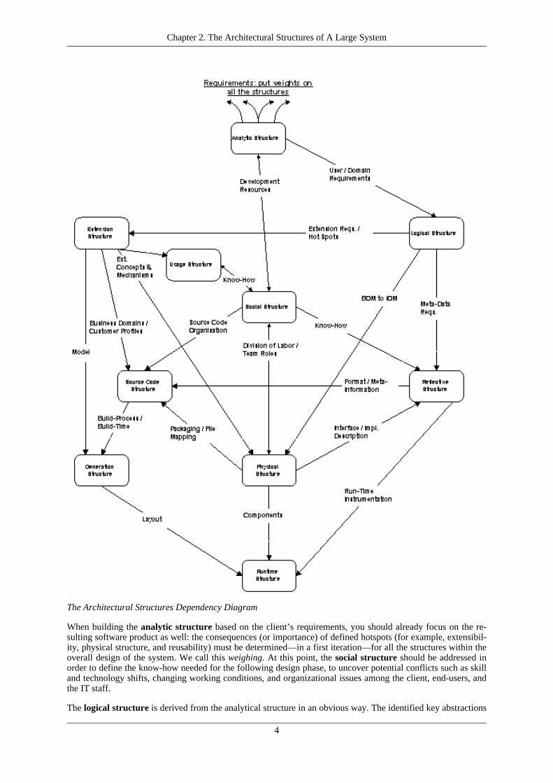
The following diagram depicts the set of architectural structures and their dependencies upon each other. Downarrows symbolize the impact of an architectural structure upon another; mutual dependencies are indicated witha single arrow on each end of the dependency. The annotations on the diagram’s edges describe the key aspectsof a structural dependency upon another.
Chapter 2. The Architectural Structures of A Large System
3
The Architectural Structures Dependency Diagram
When building the analytic structure based on the client’s requirements, you should already focus on the re-sulting software product as well: the consequences (or importance) of defined hotspots (for example, extensibil-ity, physical structure, and reusability) must be determined—in a first iteration—for all the structures within theoverall design of the system. We call this weighing. At this point, the social structure should be addressed inorder to define the know-how needed for the following design phase, to uncover potential conflicts such as skilland technology shifts, changing working conditions, and organizational issues among the client, end-users, andthe IT staff.
The logical structure is derived from the analytical structure in an obvious way. The identified key abstractions
Chapter 2. The Architectural Structures of A Large System
4
and generic constructs will be used to specify the extension structure. Also, the business part of the reflectivestructure should be available at this point. In addition, the logical structure influences the physical structure,since you cannot transform the resulting business object model (BOM) into an implementation object model(IOM) in a trivial way most of the time.
The design of the physical structure requires detailed know-how and experience of the target and implementa-tion environment. Input must be provided from the social structure, for example, in terms of considering thenumber of developers involved and decreasing the resulting dependencies in order to minimize build-time; theextension structure, for example, in terms of modeling extension concepts and mechanisms. Since the physicalstructure determines the components, their collaborations, and the chosen implementation technique, the run-time structure (in terms of which components will be used when, where, and how), the source code structure(in terms of managing the component source code), as well as the reflective structure (in terms of providingrun-time component information) will all be influenced.
Example: How large-scale System Topics Depend On Connected Struc-tures
We will try to explain some more aspects of the dependency diagram above by mapping some hot topics likereuse, extendibility and reliability onto the architectural structures and the connections between them. Under-standing them will be a prerequisite for the second step: building a catalog of technologies that can be used inthe structures to achieve the specific goals.
Reuse
Reuse in large-scale development is both at the same time extremely necessary as well as very hard to achieve.Many structures are involved in creating reusable „things" (classes, modules, descriptions etc.). The most impor-tant of them being the usage structure –it defines ways and levels of reuse like white box versus black box reuse,the social structure (it must make sure that the necessary skills and procedures are in place to enable reuse) andthe physical structure that must provide mechanism that enable convenient and reliable forms of reuse (like dy-namic class loading, packaging etc.) No doubt that the physical mechanisms for reuse need a logical representa-tion (APIs, factories, orbs, naming services). The reusable „things" themselves might need to be collected inrepositories (interface and implementation rep.) or need a meta – information (reflection) structure because ofthe generic way they work. With reuse problems one works at the same time on high level concepts as well asdeep down in the trenches of C++ limitations due to link-time dependencies etc. The forces involved will manytimes compete against each other. While having „modules" combine certain functionality into packages thathide the internals from others, one might want to (re-) use many of these internals in other places. A fine grainedreuse structure needs a specially architected social structure in place due to its high communication and organi-zation requirements. This is quite different to a coarse grain module based approach with its divide and conquerattitude.
Extendibility
Why isn‘t there an „accidental" flexibility in a large-scale system? Why can‘t we have an „extension module"?Because, like reuse, flexibility touches too many structures concurrently. The extension structure defines targets(hot spots) and mechanisms to reach flexibility. This causes the logical structure to respects those by represent-ing the concepts (object bus, registrations policies etc.) and the physical structure by providing more mecha-nisms to achieve this flexibility. This can range from a compile – based extension approach all the way up to asystem that can dynamically change or add services (hot swap, replication) possibly with an integrated develop-ment system.
Reliability
Even more than reuse and extendibility, reliability touches almost all structures in a system. It might even payoff to define it as an extra structure to raise the level of attention. One of the first places where reliability issuesshow up in large system is the development and build process. With a large team involved, interactive develop-ment environments tend to break down because they are not team enabled and cannot be used in an automatedmode. The source code structure will control access and organization of the source code itself. The generationstructure will set up the symbolic environment for all development and generate a programming environment aswell as the complete or partial versions of the system. This cannot require manual interaction. But the genera-tion structure will do even more. It will insert administrative values into the source code during build time orcreate repositories from the build time information. The source code structure will have to provide the necessarymacros for this to be possible. And the runtime structure will use these values to check for interface (perhaps
Chapter 2. The Architectural Structures of A Large System
5
even implementation) compatibility and perform logging, error handling and health checking. Due to the inter-action between these structures, the system will be able to inspect itself and give information about itself duringbuild and runtime.
There are many more issues to reliability with consequences for all the structures in the system and their con-nections. Issues from the extension structure or the usage structure require in many cases a loosening of statictyping. The resulting loss in reliability must be regained by using a reflection structure that controls the nowsymbolic definitions. This can lead to the integration of a whole sub-framework dealing with nothing else butthe „information architecture" of a system, e.g. an SGML-based validation engine.
Chapter 2. The Architectural Structures of A Large System
6
Chapter 3. Architectural Structures andThe Software Development Process
We argue that during any comprehensive software development process, it becomes vitally important to con-sider the set of architectural structures and their impacts upon each other early on and continuously during thedevelopment process. The following principles guide us in linking the set of architectural structures with thesoftware development process:
1. Simultaneousness / Parallelity: Domain analysis and software design have strong impacts on each other.Therefore, the consideration of the architectural structures within the development process needs to happenin parallel and not in a chronological, sequential fashion. Moreover, this should happen early on, ideallyduring the analysis phase, or at least during the logical design phase.
2. Completeness: Not all the architectural structures have to be implemented within a system’s architecture,but they should all be considered within the development process early on.
3. Weighing: With respect to user requirements, a weight should be assigned to the importance of a particulararchitectural structure within the context of the system’s architecture. This enables us to instantiate thestructure diagram and use it as target diagram.
4. Constant Tracking: As the development process progresses, the state and the importance of the architec-tural structures for the system’s architecture should be tracked constantly. This will enable the developmentteam to derive a system design rating – a measure of the quality, completeness and the tractability of theirefforts.
5. Definition of Mechanisms: For each architectural structure under consideration, the development teamshould be able to define mechanisms that render transparent the implementation of this structure. Theircombination leads to a concise description for the underlying architecture and the development process.
7
Chapter 4. Quantifying Design QualityBased on Architectural Structures
The previous chapters introduced architectural structures and their link to the development process as an aid toachieve and preserve design quality through a sophisticated, comprehensive and functional architecture. Since alot of people prefer to quantify quality in order to discuss and rate a systems design, we will now set up a designquality metric based on the architectural structures defined above.
RequirementsOur requirements for such a metric are: Simplicity, strength, relativity to requirements, objectivity and trans-parency. Poor designs shall be rated with 0, professional ones with 1. We do not want to present here the finalmagic formula rather than suggest an initial direction.
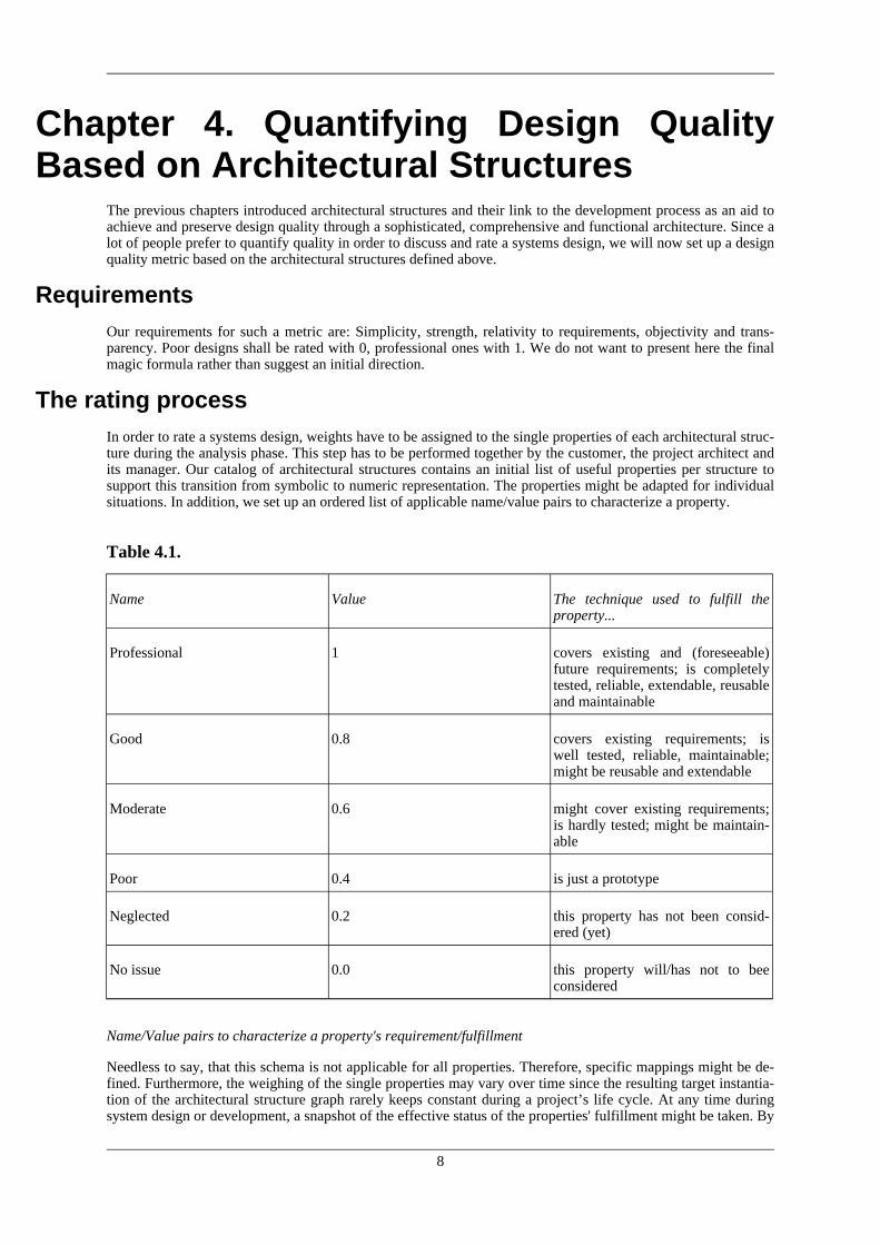
The rating processIn order to rate a systems design, weights have to be assigned to the single properties of each architectural struc-ture during the analysis phase. This step has to be performed together by the customer, the project architect andits manager. Our catalog of architectural structures contains an initial list of useful properties per structure tosupport this transition from symbolic to numeric representation. The properties might be adapted for individualsituations. In addition, we set up an ordered list of applicable name/value pairs to characterize a property.
Table 4.1.
Name Value The technique used to fulfill theproperty...
Professional 1 covers existing and (foreseeable)future requirements; is completelytested, reliable, extendable, reusableand maintainable
Good 0.8 covers existing requirements; iswell tested, reliable, maintainable;might be reusable and extendable
Neglected 0.2 this property has not been consid-ered (yet)
No issue 0.0 this property will/has not to beeconsidered
Name/Value pairs to characterize a property's requirement/fulfillment
Needless to say, that this schema is not applicable for all properties. Therefore, specific mappings might be de-fined. Furthermore, the weighing of the single properties may vary over time since the resulting target instantia-tion of the architectural structure graph rarely keeps constant during a project’s life cycle. At any time duringsystem design or development, a snapshot of the effective status of the properties' fulfillment might be taken. By
8
comparing the targeted and the effective status of the properties' values a rating of the systems quality can be de-rived relative to it’s requirements.
The formulaAnd here is the magic metric, straightforward:
: A metric for rating a systems design
Although the formula may scare some readers first, it is quite simple to explain and implement as spreadsheet:First we compute and sum the differences of the targeted and the effective fulfillment of the properties of an ar-chitectural structure within our design (term T1):
The resulting figure is then normalized with the number of the target properties (which is equal the number ofeffective properties) of an architectural structure (term T2):
Since we expect the target to be achieved, the difference per architectural structure is term T3: 1 – T2. Finally,we sum these differences T3 of every architectural structure and normalize it with the number of architecturalstructures involved (term T4):
This metric allows us to detect positive or negative deviations of the systems design requirements, to identifyweaknesses on property as well as on architectural structure level and hence to quantify a systems relative de-sign quality in an easy way.
Chapter 4. Quantifying Design Quality Based on Architec-tural Structures
9
Obviously, every other formula computing a figure from 0 to 1 by comparing target and effective design thatfollows the requirements listed above would be appropriate. Also sophisticated extensions would be easily pos-sible – e.g. by marking important properties and/or structures with weights, to punish property value differencesrelative to the target property value, aso. The difficulty herein is not the composition of a fancy formula but:First the identification of the architectural structure’s properties and second the comparison of the targeted andthe effective fulfillment of a property.
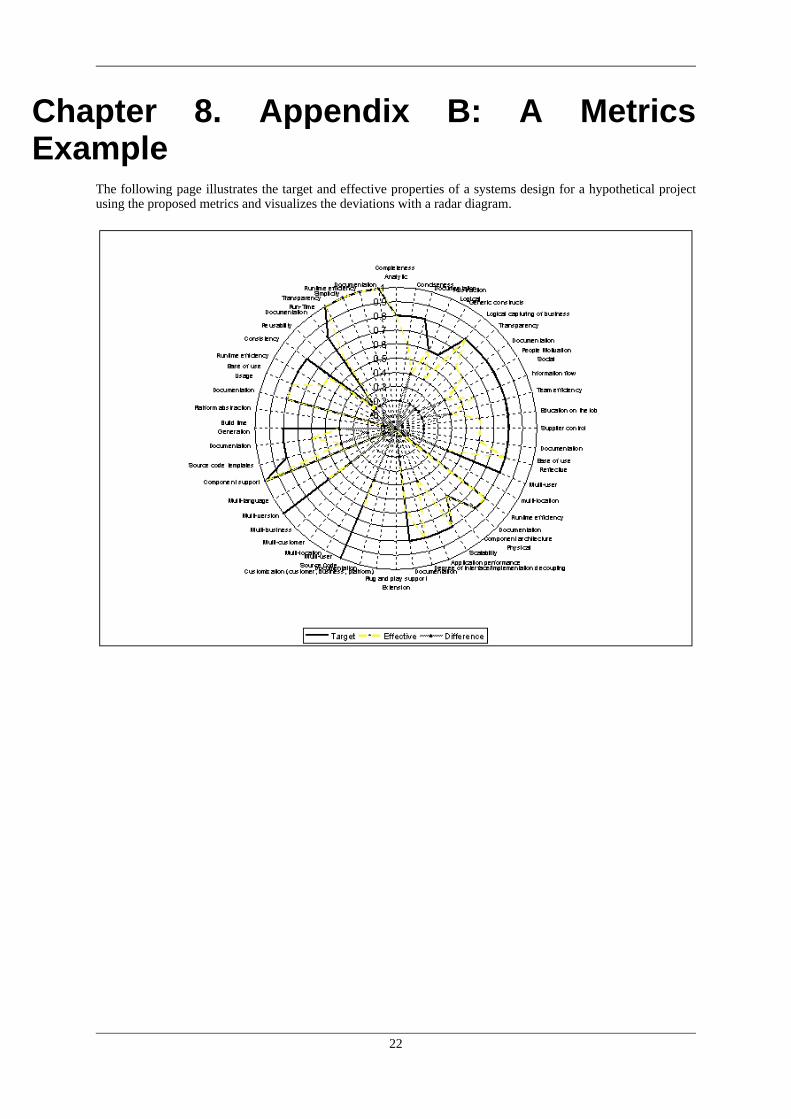
An ExampleFor illustration, we compared the target and effective properties of a systems design for a hypothetical projectusing the metric above and visualized the deviations with a radar diagram (see Appendix B).
Chapter 4. Quantifying Design Quality Based on Architec-tural Structures
10
Chapter 5. ConclusionThe consideration of the set of architectural structures defined in this paper augment the software developmentprocess by making transparent properties within the architecture of a large system that are usually invisible, dif-ficult to explain, and hard to visualize. In this sense, architectural structures are not design patterns [2]; rather,they are structures of a larger granularity in whose implementation design patterns could be used. The architec-tural structures enable designers and implementers of large systems to decompose the system’s requirementsinto several categories of structures, and consequently to derive a system architecture that is sophisticated andcomprehensive
The important conclusion for us is that the structures have to be made explicit, well defined, constantly adoptedand discussed. All engineers have to be aware of them to ensure the overall architectural integrity of a system.
Ideally, the by-product of this meshing of the architectural structures, the software development process, and theuser requirements could be a handbook for the development of the software system. It will tell the developmentteam, for example, how the source code should be structured; how the software is to be extended; how the workof each developer can be decoupled from the work of the other.
11
Chapter 6. AuthorsWalter Kriha, Daniel Kesch, and Stephan Pluess are all project architects for SYSTOR Corporation in Switzer-land. They have been developing applications and architectures for large banking projects.
12
Chapter 7. Appendix A: An ArchitecturalStructures Catalog
The following pages present the architectural structures that we have identified in a catalog format. Along thelines of the Gang of Four book on Design Patterns, we have tried describe the architectural structures in a cer-tain format.
In this catalog, an architectural structure has six essential elements:
1. The architectural structure name that we can use to identify certain aspects during the design of a large sys-tem.
2. The motivation behind the architectural structure.
3. The responsibilities the architectural structure is to carry out.
4. The properties of this architectural structure.
5. The collaboration(s) of this architectural structure with other architectural structures.
6. The consequences of this architectural structure in terms of trade-offs in its use.
Analytical Structure
Motivation
The analytic structure must consider not only the user and domain requirements first and foremost, but also thetarget software product itself. This can be accomplished by putting weights on all the other involved architec-tural structures and by specifying their desired properties. This important basic step determines the software’sfoundation for successfully designing, building, running and maintaining the system.
Responsibilities
• Requirement analysis: What the customer precisely does or does not expect from the system with respect tobusiness, technical and operational points of view.
• Decomposition into key abstractions: What are the basic constructs the requirements do consist of?
• Hotspot Analysis: Which implementations of the key abstractions have to be designed with special regard toabstraction, encapsulation, extension, exchangeability, reuse and/or maintenance?
• Internal product characterization: Which architectural structures are of inherent importance – reflected bytheir desired properties and weights – for the success of the project?
Properties
• Completeness
• Conciseness
• Documentation
Collaborations
13
• Defines importance and desired properties of all other architectural structures
The logical structure addresses the factorization of the problem domain without regard for physical components.
Responsibilities
The elements of the logical structure define, among others:
• the architecture’s central abstractions; for example, the used document model
• the object model (root classes, helper classes, concrete classes)
• the derivation tree (base classes, default implementations, application-specific derivations)
• the design patterns used
• the usage rules with respect to, for example, memory management, object creation, and reference counting
• logical aspects of the separation between interfaces and implementation
• logical aspects of sharing object between applications
• the separation between the architecture’s layers (GUI, BOM, Data Access)
• the impact support other application-specific requirements:
• transaction management
• user security
• Undo/Redo functionality
• national language support
Properties
• Abstraction
• Generic constructs
• Logical capturing of business entities and processes
• Transparency
• Documentation
Collaborations
Chapter 7. Appendix A: An Architectural Structures Catalog
14
• The identified hot spots define the requirements of the extension structure
• The mapping of the business object model to the implementation object model influences the physical struc-ture
• Business meta data, that must be programatically available, specifies a part of the reflective structure
Consequences
The separation between the logical structure and the physical structure is an intellectual one—both structureshave impacts on each other.
Social Structure
Motivation
The social structure defines how the development team, information flow and external contacts are to be orga-nized and how the roles within the team are to be distributed among the project team members with regard toknow-how and experience: The foundation for successful and efficient development.
Responsibilities
• Team organization: Administrative issues, meeting structure, management of skill and/or technology shifts.
• Labor division: Business versus technical labor assignment with people backup concept.
• Information flow: Know-how and news distribution.
• Contacts: Fix points for business and technical questions of external as well as internal persons and customercare.
• Roles: Clear assignment of roles and responsibilities.
Properties
• People motivation
• Information flow
• Team efficiency
• Education on the job
• Supplier control
• Documentation
Collaborations
• Usage structure (negative): Due to skill/technology shift or lack of know-how, the acceptance of a compo-nent’s interface might be revoked.
• Reflective structure: For a large project team and/or complex business covered, the core design and imple-mentation concepts have to be programatically available.
• Physical structure: The more people are working on a project, the more important are not only concise inter-faces but also their decoupling of the implementation.
Chapter 7. Appendix A: An Architectural Structures Catalog
15
• Source code structure: A large project team requires a professional component-based source code manage-ment.
Consequences
• Bad development team performance
Reflective Structure
Motivation
The reflective structure captures the self-describing, programatically available aspects of the system in terms ofmeta-data of both, the business domain as well as the software product itself.
Responsibilities
• Runtime instrumentation of hot spots: Support of configuration data or plug-and-play components.
• Runtime object and/or service repository.
• Meta data repositories such as architecture, object and/or database descriptions.
• Automatic source code documentation.
• Ease of use
• Multi-user
• Multi-location
• Runtime efficiency
• Documentation
Collaborations
• Source code structure: Depending on the tool used, the source code has to be organized in an appropriateway.
• Runtime structure: The reflective structure determines the components used at runtime.
Consequences
• Insufficient flexibility through cold spots.
• Redundancy due to missing central repository.
• Lack of source code overview.
Physical Structure
Chapter 7. Appendix A: An Architectural Structures Catalog
16
Motivation
The physical structure addresses the issues surrounding the physical entities of the system and their relationshipswith each other
Responsibilities
The elements of the physical structure define:
• the compile- and link-time dependencies of object modules
• the separation of interfaces and implementation
• the division of repositories and other configuration information into physical entities
• the packaging of object modules into components (or packages) and the definition of the contained function-ality
• the compile- and link-time dependencies among the components
• the form of component delivery: DLLs, libraries, executables
• the consideration of performance aspects; for example, the degeneration of the application’s implementationwith regard to the number or size of objects
• the scaling structure: where does the architecture contain cold spots that physically do not scale when the ar-chitecture is extended?
• the mechanisms behind object creation or object factories
• Component architecture requires information available from the reflective structure at runtime
Consequences
For the physical structure to be an efficient one, it depends on the mechanisms defined within the logical struc-ture (classes, object model, rules).
Another important physical structure aspect is the consideration of the characteristics of the underlying pro-
Chapter 7. Appendix A: An Architectural Structures Catalog
17
gramming language. For example, for C++ this means extensive developer know-how of:
• the meaning, structure, and usage of a C++ class’s VTABLE construct when dealing with single or multipleinheritance
• the handling of compiler-generated methods (where and why are they generated?)
• the compiler-dependent object layout
• the consequences of source changes on the binary layout
• the name mangling and dynamic loading of modules
• the problems with static initialization
• the consequences of using inlines, templates, and default parameters
Extension Structure
Motivation
The extension structure addresses all the aspects necessary for the customization and the extension of the sys-tem, respectively.
Responsibilities
The elements of the extension structure define:
• concepts and mechanisms for extending the system
• defined processes
Properties
• Plug and play support
• Customization in terms of business, company, platform extendibility
• Documentation
Collaborations
• Extension concepts and mechanisms are reflected by the physical structure
• Customizations influence the source code structure and the generation structure in order to create business,company or platform specific versions
Consequences
The extension structure must make transparent the implications of an in itself vast spectrum of possibilities:from a highly dynamic and flexible extension structure to a completely static build- and reinstall extensionstructure.
Chapter 7. Appendix A: An Architectural Structures Catalog
18
Source Code Structure
Motivation
The source code structure addresses the management of the system’s source code within a development team.
Responsibilities
The elements of the source code structure define:
• how new source code is created
• where the source code is to be placed
• what conventions govern the creation and use of the source code
• how the source code is administered
Properties
• Multi-user
• Multi-location
• Multi-customer
• Multi-business
• Multi-version
• Multi-language
• Component support
• Source code templates
• Documentation
Collaborations
• Depending on the source code structure, the generation structure has to be defined
Consequences
The bigger and the more complex the system’s source code base is, the more things should be automated andteam-enabled.
Generation Structure
Motivation
The generation structure defines the dependable and automatic construction of the system (i.e. its parts and itsconfiguration).
Responsibilities
The elements of the generation structure define:
Chapter 7. Appendix A: An Architectural Structures Catalog
19
• the build process
Properties
• Build time
• Platform abstraction
• Documentation
Collaborations
• Depending on what kind of and how many components will be generated, the runtime structure looks differ-ent
Consequences
Automate as much as possible. This can be accomplished through support in the source code structure. Keep thedescription of the system’s build structure in an abstract, logical notation. Map this description in each case tothe required physical form (i.e. Make file for Unix, NT, etc.)
Usage Structure
Motivation
The usage structure defines how developers use what and when and how reuse is to be implemented. By choos-ing a consistent model throughout the architecture, people may easily switch between different roles and hencesave time.
Responsibilities
• White versus black-box reuse
• Interface/implementation decoupling
• Object navigation
• API documentation
Properties
• Ease of use
• Runtime efficiency
• Consistency
• Reusability
• Documentation
Collaborations
Chapter 7. Appendix A: An Architectural Structures Catalog
20
• Social structure: A skill/technology shift due to a usage model requires changes in people management.
Consequences
• Developer acceptance might be revoked due to inappropriate usage structure
Run-Time Structure
Motivation
The run-time structure defines how the system is to be set running and how it is to behave over a period of time.
Responsibilities
• Define the system’s preconditions regarding 3rd party hard- and software
• Enumerate required components and services with their versions
• Specify the component’s/service’s accessibility
• Describe the boot process, resource allocation, as well as logging, tracing and error handling mechanisms
Chapter 7. Appendix A: An Architectural Structures Catalog
21
Chapter 8. Appendix B: A MetricsExample
The following page illustrates the target and effective properties of a systems design for a hypothetical projectusing the proposed metrics and visualizes the deviations with a radar diagram.
22
Chapter 9. Appendix C: List of References[1] Kruchten, P., Software Architecture & Iterative Development, RATIONAL, Rev. 9, July 27, 1994, Vancou-ver B.C. V6P 5H2
[2] Gamma, E., et. al., Design Patterns: Elements of Reusable Object-Oriented Software,