+ All Categories
Home > Documents > Architectural Testingdealerschoiceaz.com/dc_technical_info/nfrc_6000_vinyl... · 2012. 11. 29. ·...

Architectural Testingdealerschoiceaz.com/dc_technical_info/nfrc_6000_vinyl... · 2012. 11. 29. ·...

Date post: 03-Mar-2021
Category:
Upload: others
View: 2 times
Download: 0 times
Share this document with a friend
27
NFRC U-FACTOR, SHGC, VT, & CONDENSATION RESISTANCE COMPUTER SIMULATION REPORT Rendered to: PARAMOUNT WINDOWS CORPORATION SERIES/MODEL: ECO-View 6100/7100 Report Number: Report Date: Expiration Date: B6000.01-301-45 02/20/12 01/27/16 Architectural Testing 130 Derry Court York, PA 17406-8405 phone: 717-764-7700 fax: 717-764-4129 www.archtest.com
Transcript

NFRC U-FACTOR, SHGC, VT, &

CONDENSATION RESISTANCE

COMPUTER SIMULATION REPORT

Rendered to:

PARAMOUNT WINDOWS CORPORATION

SERIES/MODEL:

ECO-View 6100/7100

Report Number:

Report Date:

Expiration Date:

B6000.01-301-45

02/20/12

01/27/16

Architectural Testing

130 Derry Court York, PA 17406-8405 phone: 717-764-7700 fax: 717-764-4129 www.archtest.com

NFRC U-FACTOR, SHGC, VT, & CONDENSATION RESISTANCE

COMPUTER SIMULATION REPORT

Rendered to:

PARAMOUNT WINDOWS CORPORATION

550 West Southern Ave

Tempe, Arizona 85282

Report Number:

Simulation Date:

Report Date:

Expiration Date:

Project Summary:

Standards:

Software:

Simulations Specimen Description:

Series/Model: ECO-View 6100/7100

Type: Vertical Slider , Single Hung 

Frame Material: VY Vinyl 

Sash Material: VI Vinyl w/ Reinforcement - Interlock 

Standard Size: 1200mm x 1500mm

B6000.01-301-45

01/27/12

02/20/12

01/27/16

Architectural Testing, Inc. was contracted to perform U-Factor, Solar Heat Gain Coefficient,

Visible Transmittance, and Condensation Resistance* computer simulations in accordance with

the National Fenestration Rating Council (NFRC). The products were evaluated in full

compliance with NFRC requirements to the standards listed below.

*NFRC's Condensation Resistance rating is NOT equivalent to a Condensation Resistance

Factor (CRF) determined in accordance with AAMA 1503.

NFRC 100-2010: Procedure for Determining Fenestration Product U-Factors

NFRC 200-2010: Procedure for Determining Fenestration Product Solar Heat Gain

Coefficient and Visible Transmittance at Normal Incidence

NFRC 500-2010: Procedure for Determining Fenestration Product Condensation

Resistance Values

Frame and Edge Modeling: THERM 6.3.19

Center-of-Glass Modeling: WINDOW 6.3.9

Total Product Calculations: WINDOW 6.3.9

Spectral Data Library: 21.0

Architectural Testing

130 Derry Court York, PA 17406-8405 phone: 717-764-7700 fax: 717-764-4129 www.archtest.com

B6000.01-301-45

Page 2 of 9

Modeling Assumptions/Technical Interpretations:

1) To prevent air infiltration, tape was applied to all interior sash crack locations.

2) Center-of-glass grouping of SS and DS options per NFRC 100-2010, Section 4.2.4.1.

SS options are the group leaders.

3) Frame R1006 and R1744 are groupable per NFRC 100-2010, Section4.2.4.3.

Frame R1744 is the group leader.

Specialty Products Table:

SHGC = SHGC0 + SHGCc (SHGC1 - SHGC0)

VT = VT0 + VTc (VT1 - VT0)

Validation Matrix:

The specialty products method allow the manufacturer to determine the overall product SHGC

and VT for any glazing option. The center of glass SHGC and/or VT must be determined using

WINDOW 6.3.9. The method gives overall product SHGC and VT indexed on center of glass

properties. All values used in the calculations are truncated to six decimal place precision.

No Dividers Dividers < 1 Dividers > 1

SHGC0 0.004837 0.007640 0.010285

SHGC1 0.815070 0.731657 0.652924

VT0 0.000000 0.000000 0.000000

VT1 0.810233 0.724017 0.642639

The following products are part of a validation matrix. Only one is required for validation

testing.

Product Line Report Number

ECO-View 6200/7200 Horizontal Sliding

Window

B5998.01-301-45

ECO-View 6100/7100 Single Hung Window B6000.01-301-45

Architectural Testing

B6000.01-301-45

Page 3 of 9

Spacer Option Description

Grid Option Description

Reinforcement Option Description

Gas Filling Technique Description

Edge-of-Glass Construction

Weatherstripping

Frame/Sash Materials Finish

Sealant

Spacer Type Primary Secondary Code

Truseal Duralite Spacer Butyl Rubber P1-S

Truseal Duraseal Spacer Butyl Rubber A8-S

Grid Size Grid Type Grid Pattern

0.118" x 0.813" Aluminum Rectangular Grid - Painted NFRC Standard

Location Material

Lockstile Galvanized

Impost Aluminum

Fill Type Method

90% Argon Single Probe - Timed

Interior Condition Glazing tape betweeen glass and frame

Exterior Condition Glazing Bead against glass

Type Quantity Location

Mohair 2 Rows Interlock

Mohair 1 Row Bottom Rail & Stiles

Interior Vinyl

Exterior Vinyl

Architectural Testing

NFRC 100/200/500 Summary Sheet

ECO-View 6100/7100

Ga

p F

ill

Lo

w-e

(S

urf

ace

#)

Tin

t

Sp

ace

rID

Pa

ne

Th

ick

nes

s 1

Ga

p W

idth

1

Pa

ne

Th

ick

nes

s 2

Ga

p W

idth

2

Pa

ne

Th

ick

nes

s 3

Gri

d T

yp

e

U-FactorSolar Heat Gain Coefficient (SHGC)

Grids (None / <1 / >=1)

Visible Transmittance (VT)

Grids (None / <1 / >=1)

Condensation

Resistance

Ga

p W

idth

3

Pa

ne

Th

ick

nes

s 4

1 Clr / Air / Clr - 3/4 - (SS-SS)

0.090 0.563 0.090 AIR CL A8-S N,G

U-Factor 0.48 SHGC (N / >1) 0.65 / 0.52 VT (N / >1) 0.67 / 0.53 CR 43

Page 4 of 9

B6000.01-301-45

Clr / Air / Clr - 3/4 - (DS-DS)

0.117 0.500 0.117 AIR CL A8-S N,G

U-Factor 0.48 SHGC (N / >1) 0.64 / 0.51 VT (N / >1) 0.67 / 0.53 CR 43

2 RLE 5527 / Air / Clr - 3/4 - (SS-SS)

0.090 0.563 0.090 AIR

U-Factor 0.34 SHGC (N / >1) 0.23 / 0.19 VT (N / >1) 0.45 / 0.35

0.024(#2) CL A8-S N,G

A8-S N,G

CR 54

3 RLE 5527 / Air / RLE 5527 - 3/4 - (SS-SS)

0.090 0.563 0.090

VT (N / >1) 0.30 / 0.24

AIR 0.024(#2) / 0.024(#3) CL

U-Factor 0.33 SHGC (N / >1) 0.20 / 0.17

A8-S N,G

CR 54

RLE 5527 / Air / Clr - 3/4 - (DS-DS)

0.117 0.500 0.117

VT (N / >1) 0.44 / 0.35

AIR 0.024(#2) CL

U-Factor 0.33 SHGC (N / >1) 0.23 / 0.19

A8-S N,G

CR 54

RLE 5527 / Air / RLE 5527 - 3/4 - (DS-DS)

0.117 0.500 0.117

VT (N / >1) 0.30 / 0.23

AIR 0.024(#2) / 0.024(#3) CL

U-Factor 0.33 SHGC (N / >1) 0.20 / 0.17

A8-S N,G

CR 54

4 RLE 5527 / Arg / Clr - 3/4 - (SS-SS)

0.090 0.563 0.090

VT (N / >1) 0.45 / 0.35

ARG90 0.024(#2) CL

U-Factor 0.30 SHGC (N / >1) 0.23 / 0.19

A8-S N,G

CR 57

5 RLE 5527 / Arg / RLE 5527 - 3/4 - (SS-SS)

0.090 0.563 0.090

VT (N / >1) 0.30 / 0.24

ARG90 0.024(#2) / 0.024(#3) CL

U-Factor 0.30 SHGC (N / >1) 0.20 / 0.16

A8-S N,G

CR 57

RLE 5527 / Arg / Clr - 3/4 - (DS-DS)

0.117 0.500 0.117

VT (N / >1) 0.44 / 0.35

ARG90 0.024(#2) CL

U-Factor 0.30 SHGC (N / >1) 0.23 / 0.19

A8-S N,G

CR 57

RLE 5527 / Arg / RLE 5527 - 3/4 - (DS-DS)

0.117 0.500 0.117

VT (N / >1) 0.30 / 0.23

ARG90 0.024(#2) / 0.024(#3) CL

CR 57U-Factor 0.30 SHGC (N / >1) 0.20 / 0.16

Architectural Testing

B6000.01-301-45

Page 5 of 9

NFRC 100/200/500 Summary Sheet

ECO-View 6100/7100

Ga

p F

ill

Lo

w-e

(S

urf

ace

#)

Tin

t

Sp

ace

rID

Pa

ne

Th

ick

nes

s 1

Ga

p W

idth

1

Pa

ne

Th

ick

nes

s 2

Ga

p W

idth

2

Pa

ne

Th

ick

nes

s 3

Gri

d T

yp

e

U-FactorSolar Heat Gain Coefficient (SHGC) Visible Transmittance (VT) Condensation

Grids (None / <1 / >=1) Grids (None / <1 / >=1) Resistance

Ga

p W

idth

3

Pa

ne

Th

ick

nes

s 4

6 Clr / Air / Clr - 3/4 - (4mm-4mm)

0.151 0.438 0.151 AIR

U-Factor 0.48 SHGC (N / >1) 0.63 / 0.50 VT (N / >1) 0.66 / 0.52

CL A8-S N,G

A8-S N,G

CR 42

7 RLE 5527 / Air / Clr - 3/4 - (4mm-4mm)

0.151 0.438 0.151

VT (N / >1) 0.44 / 0.35

AIR 0.024(#2) CL

U-Factor 0.34 SHGC (N / >1) 0.23 / 0.19

A8-S N,G

CR 52

8 RLE 5527 / Air / RLE 5527 - 3/4 - (4mm-4mm)

0.151 0.438 0.151

VT (N / >1) 0.29 / 0.23

AIR 0.024(#2) / 0.024(#3) CL

U-Factor 0.33 SHGC (N / >1) 0.20 / 0.17

A8-S N,G

CR 52

9 RLE 5527 / Arg / Clr - 3/4 - (4mm-4mm)

0.151 0.438 0.151

VT (N / >1) 0.44 / 0.35

ARG90 0.024(#2) CL

U-Factor 0.30 SHGC (N / >1) 0.23 / 0.19

A8-S N,G

CR 54

RLE 5527 / Arg / RLE 5527 - 3/4 - (4mm-4mm)

0.151 0.438 0.151

VT (N / >1) 0.29 / 0.23

ARG90 0.024(#2) / 0.024(#3) CL

U-Factor 0.30 SHGC (N / >1) 0.20 / 0.17

A8-S N

CR 54

10 Clr / Air / Clr - 3/4 - (5mm-5mm)

0.182 0.375 0.182

VT (N) 0.66

AIR CL

U-Factor 0.50 SHGC (N) 0.61

A8-S G

CR 41

11 Clr / Air / Clr - 3/4 - (5mm-5mm)

0.182 0.375 0.182

VT (>1) 0.52

AIR CL

U-Factor 0.50 SHGC (>1) 0.49

A8-S N

CR 41

12 RLE 5527 / Air / Clr - 3/4 - (5mm-5mm)

0.182 0.375 0.182

VT (N) 0.44

AIR 0.024(#2) CL

U-Factor 0.36 SHGC (N) 0.24

A8-S G

CR 51

13 RLE 5527 / Air / Clr - 3/4 - (5mm-5mm)

0.182 0.375 0.182

VT (>1) 0.35

AIR 0.024(#2) CL

U-Factor 0.37 SHGC (>1) 0.19

A8-S N

CR 51

14 RLE 5527 / Air / RLE 5527 - 3/4 - (5mm-5mm)

0.182 0.375 0.182

VT (N) 0.29

AIR 0.024(#2) / 0.024(#3) CL

CR 51U-Factor 0.35 SHGC (N) 0.20

Architectural Testing

B6000.01-301-45

Page 6 of 9

NFRC 100/200/500 Summary Sheet

ECO-View 6100/7100

Ga

p F

ill

Lo

w-e

(S

urf

ace

#)

Tin

t

Sp

ace

rID

Pa

ne

Th

ick

nes

s 1

Ga

p W

idth

1

Pa

ne

Th

ick

nes

s 2

Ga

p W

idth

2

Pa

ne

Th

ick

nes

s 3

Gri

d T

yp

e

U-FactorSolar Heat Gain Coefficient (SHGC) Visible Transmittance (VT) Condensation

Grids (None / <1 / >=1) Grids (None / <1 / >=1) Resistance

Ga

p W

idth

3

Pa

ne

Th

ick

nes

s 4

15 RLE 5527 / Air / RLE 5527 - 3/4 - (5mm-5mm)

0.182 0.375 0.182 AIR

U-Factor 0.37 SHGC (>1) 0.17 VT (>1) 0.23

0.024(#2) / 0.024(#3) CL A8-S G

A8-S N

CR 51

16 RLE 5527 / Arg / Clr - 3/4 - (5mm-5mm)

0.182 0.375 0.182

VT (N) 0.44

ARG90 0.024(#2) CL

U-Factor 0.31 SHGC (N) 0.23

A8-S N

CR 54

RLE 5527 / Arg / RLE 5527 - 3/4 - (5mm-5mm)

0.182 0.375 0.182

VT (N) 0.29

ARG90 0.024(#2) / 0.024(#3) CL

U-Factor 0.31 SHGC (N) 0.20

A8-S G

CR 54

17 RLE 5527 / Arg / Clr - 3/4 - (5mm-5mm)

0.182 0.375 0.182

VT (>1) 0.35

ARG90 0.024(#2) CL

U-Factor 0.32 SHGC (>1) 0.19

A8-S G

CR 54

RLE 5527 / Arg / RLE 5527 - 3/4 - (5mm-5mm)

0.182 0.375 0.182

VT (>1) 0.23

ARG90 0.024(#2) / 0.024(#3) CL

U-Factor 0.32 SHGC (>1) 0.17

P1-S N,G

CR 54

18 RLE 5527 / Arg / Clr - 3/4 - (SS-SS)

0.090 0.563 0.090

VT (N / >1) 0.45 / 0.35

ARG90 0.024(#2) CL

U-Factor 0.28 SHGC (N / >1) 0.23 / 0.19

P1-S N,G

CR 61

19 RLE 5527 / Arg / RLE 5527 - 3/4 - (SS-SS)

0.090 0.563 0.090

VT (N / >1) 0.30 / 0.24

ARG90 0.024(#2) / 0.024(#3) CL

U-Factor 0.28 SHGC (N / >1) 0.20 / 0.16

P1-S N,G

CR 61

RLE 5527 / Arg / Clr - 3/4 - (DS-DS)

0.117 0.500 0.117

VT (N / >1) 0.44 / 0.35

ARG90 0.024(#2) CL

U-Factor 0.28 SHGC (N / >1) 0.23 / 0.19

P1-S N,G

CR 61

RLE 5527 / Arg / RLE 5527 - 3/4 - (DS-DS)

0.117 0.500 0.117

VT (N / >1) 0.30 / 0.23

ARG90 0.024(#2) / 0.024(#3) CL

U-Factor 0.28 SHGC (N / >1) 0.20 / 0.16

P1-S N,G

CR 61

20 RLE 5527 / Arg / Clr - 3/4 - (4mm-4mm)

0.151 0.438 0.151

VT (N / >1) 0.44 / 0.35

ARG90 0.024(#2) CL

CR 60U-Factor 0.28 SHGC (N / >1) 0.23 / 0.19

Architectural Testing

B6000.01-301-45

Page 7 of 9

NFRC 100/200/500 Summary Sheet

ECO-View 6100/7100

Ga

p F

ill

Lo

w-e

(S

urf

ace

#)

Tin

t

Sp

ace

rID

Pa

ne

Th

ick

nes

s 1

Ga

p W

idth

1

Pa

ne

Th

ick

nes

s 2

Ga

p W

idth

2

Pa

ne

Th

ick

nes

s 3

Gri

d T

yp

e

U-FactorSolar Heat Gain Coefficient (SHGC) Visible Transmittance (VT) Condensation

Grids (None / <1 / >=1) Grids (None / <1 / >=1) Resistance

Ga

p W

idth

3

Pa

ne

Th

ick

nes

s 4

RLE 5527 / Arg / RLE 5527 - 3/4 - (4mm-4mm)

0.151 0.438 0.151 ARG90 0.024(#2) / 0.024(#3) CL P1-S N,G

U-Factor 0.28 SHGC (N / >1) 0.20 / 0.17 VT (N / >1) 0.29 / 0.23 CR 60

21 RLE 5527 / Arg / Clr - 3/4 - (5mm-5mm)

0.182 0.375 0.182 ARG90 0.024(#2) CL P1-S N

U-Factor 0.30 SHGC (N) 0.23 VT (N) 0.44 CR 58

RLE 5527 / Arg / RLE 5527 - 3/4 - (5mm-5mm)

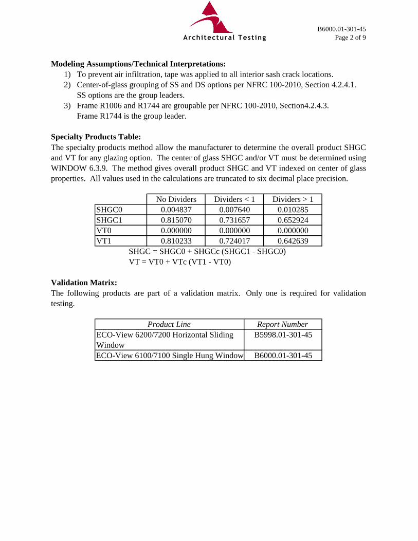
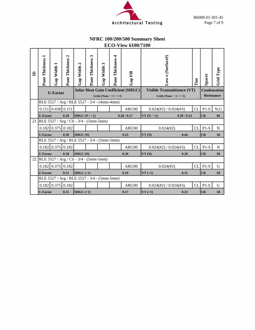
0.182 0.375 0.182 ARG90 0.024(#2) / 0.024(#3) CL P1-S N

U-Factor 0.30 SHGC (N) 0.20 VT (N) 0.29 CR 58

22 RLE 5527 / Arg / Clr - 3/4 - (5mm-5mm)

0.182 0.375 0.182 ARG90 0.024(#2) CL P1-S G

U-Factor 0.31 SHGC (>1) 0.19 VT (>1) 0.35 CR 58

RLE 5527 / Arg / RLE 5527 - 3/4 - (5mm-5mm)

0.182 0.375 0.182 ARG90 0.024(#2) / 0.024(#3) CL P1-S G

CR 58U-Factor 0.31 SHGC (>1) 0.17 VT (>1) 0.23

Architectural Testing

B6000.01-301-45

Page 8 of 9

SIMULATED BY: REVIEWED BY:

Elizabeth A. Moser Michael J. Thoman

Simulation Technician Director - Simulations and Thermal Testing

Simulator-In-Responsible-Charge

EAM:eam

B6000.01-301-45

Attachments (pages): This report is complete only when all attachments listed are included.

Appendix A: Drawings and Bills of Material (16)

For ARCHITECTURAL TESTING, INC.:

The Condensation Resistance results obtained from this procedure are for controlled laboratory

conditions and do not include the effects of air movement through the specimen, solar radiation,

and the thermal bridging that may occur due to the specific design and construction of the

fenestration system opening.

Ratings values included in this report are for submittals to an NFRC-licensed IA and are not

meant to be used directly for labeling purposes. Only those values identified on a valid

Certification Authorization Report (CAR) by an NFRC accredited Inspection Agency (IA) are

to be used for labeling purposes. The ratings values were rounded in accordance to NFRC 601,

NFRC Unit and Measurement Policy.

Architectural Testing, Inc. is an NFRC accredited simulation laboratory and all simulations

were conducted in full compliance with NFRC approved procedures and specifications. The

NFRC procedure requires that the computational results be verified through actual test results.

Detailed drawings, simulation data files, a copy of this report, or other pertinent project

documentation will be retained by Architectural Testing, Inc. for a period of four years from the

original test date. At the end of this retention period, such materials shall be discarded without

notice and the service life of this report will expire. Results obtained are simulated values and

were secured by using the designated test methods. This report does not constitute certification

of this product nor an opinion or endorsement by this laboratory. It is the exclusive property of

the client so named herein and relates only to the product simulated. This report may not be

reproduced, except in full, without the written approval of Architectural Testing, Inc.

Architectural Testing

B6000.01-301-45

Page 9 of 9

Revision Log

Rev. # Date Page(s) Revision(s)

This report produced from controlled document template ATI 00037, Revised 08/31/2009.

.01R0 02/20/12 All Original Report Issue. Work Requested by

Mr. Howard Hiebert of Paramount

Architectural Testing

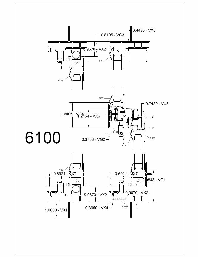
All drawings and Bills of Material used to simulate this product are enclosed in this Appendix

Appendix AB6000.01-301-45
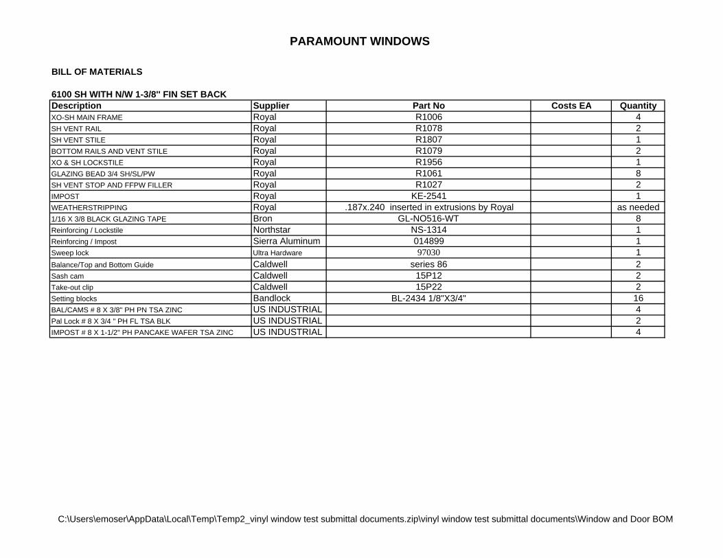
PARAMOUNT WINDOWS

BILL OF MATERIALS

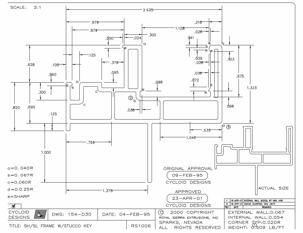
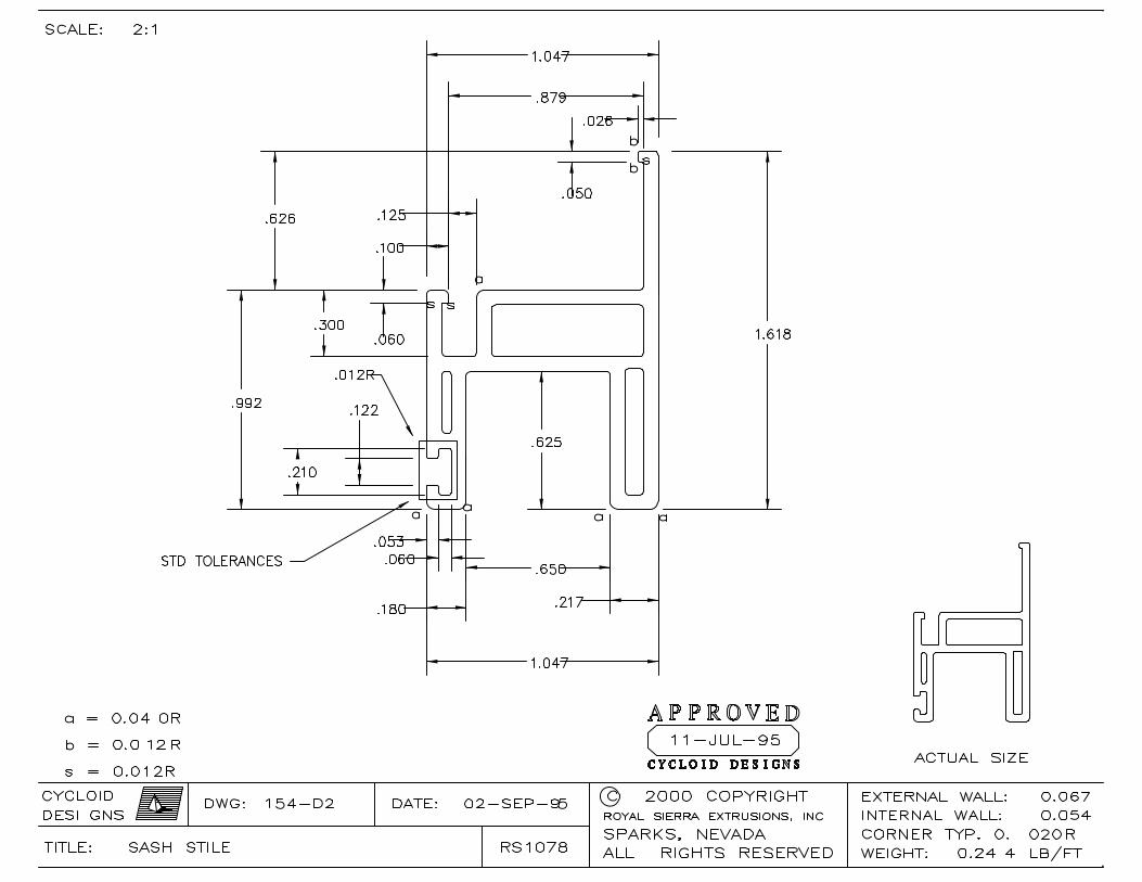
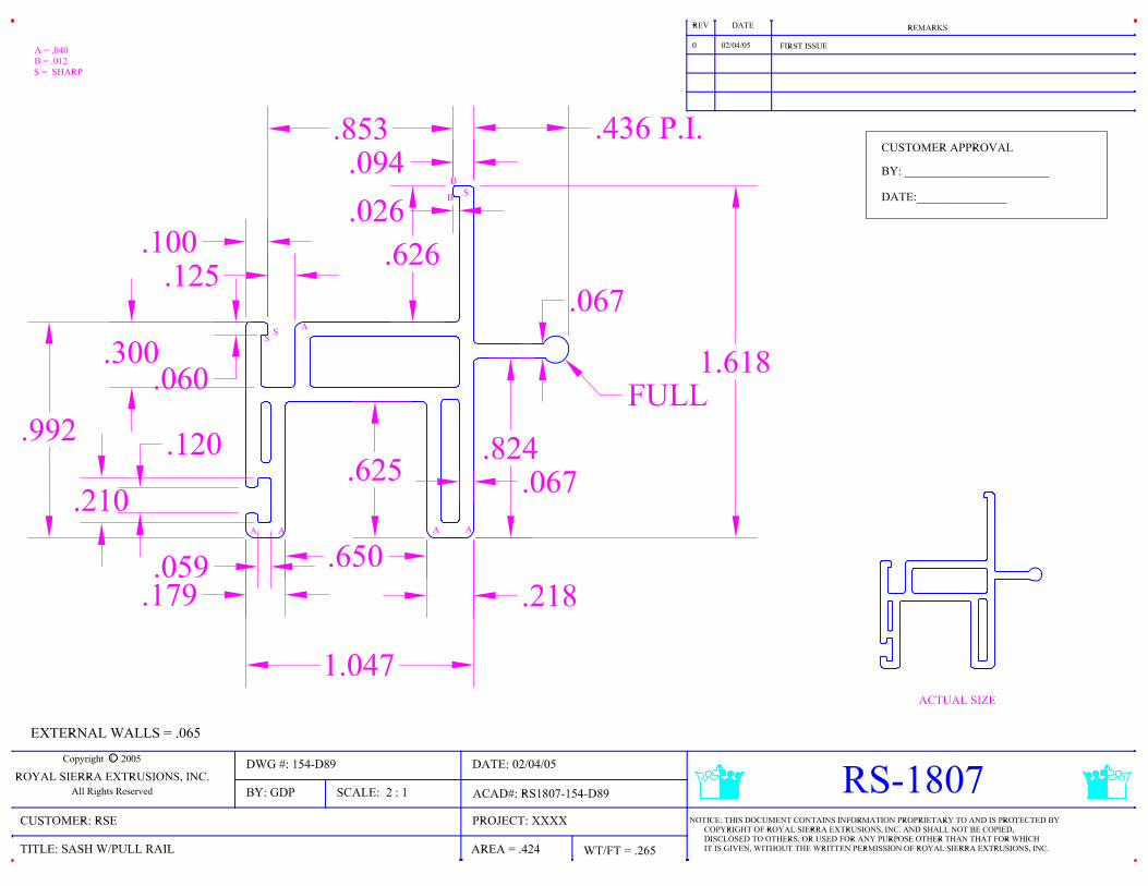
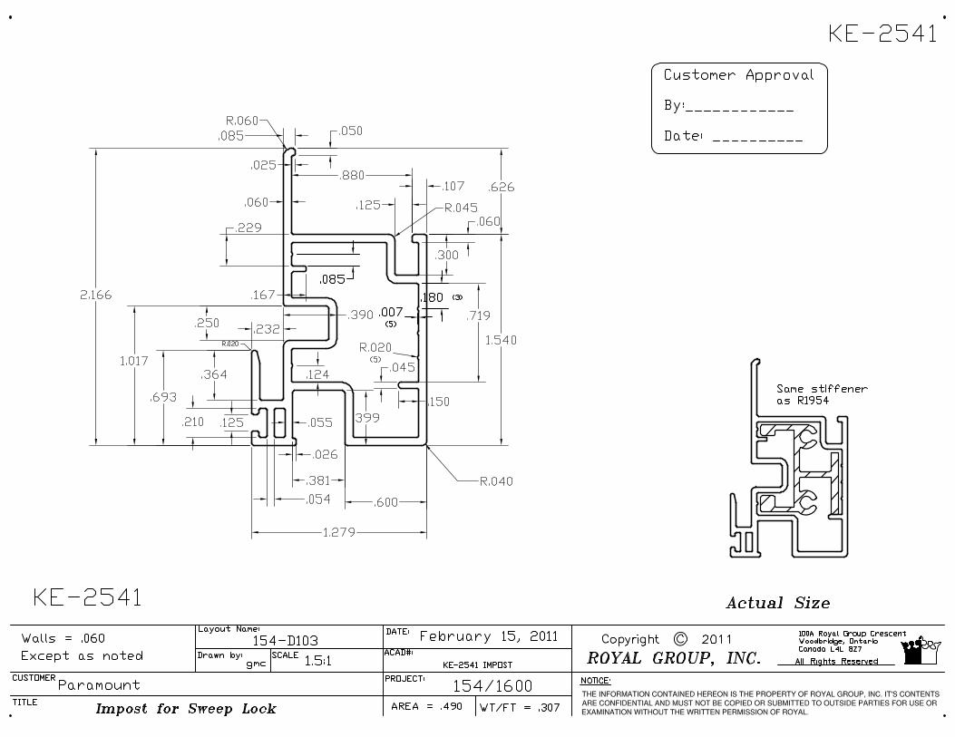
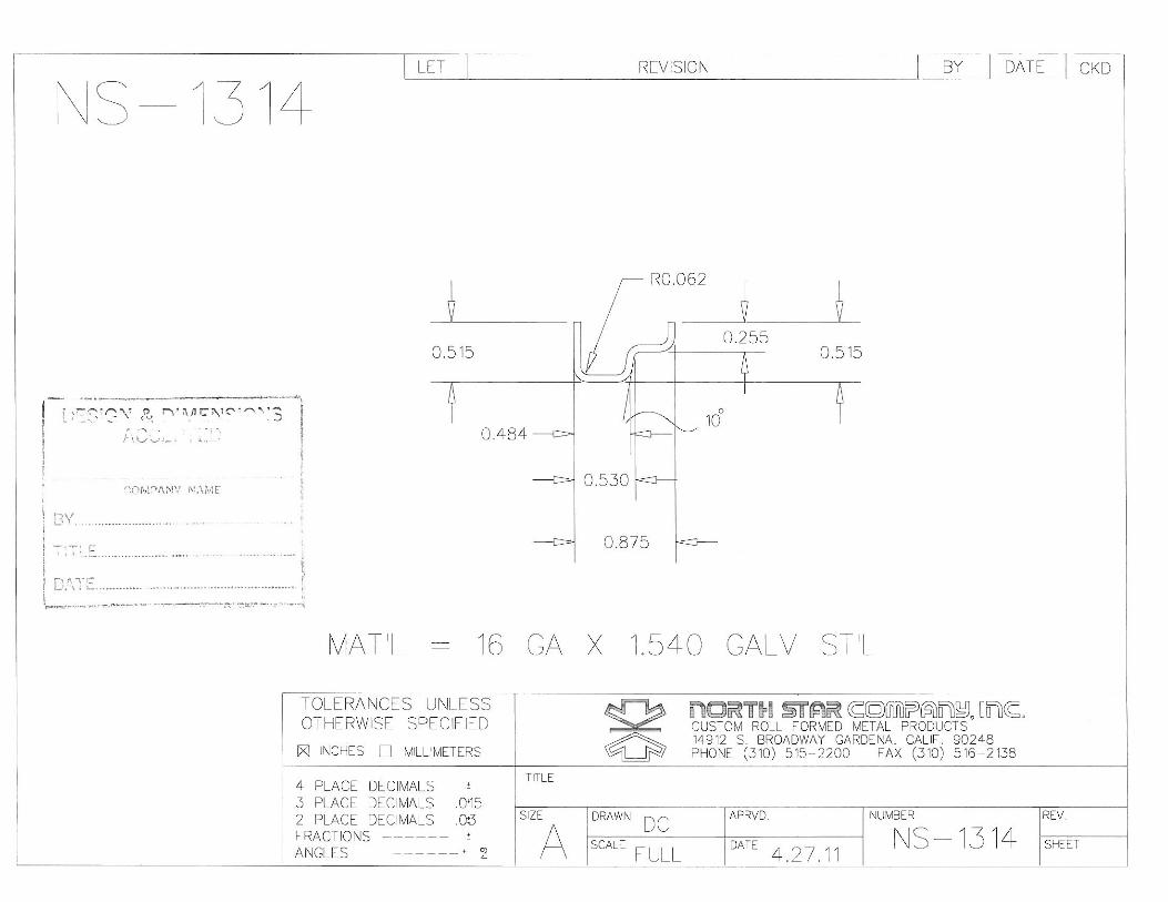
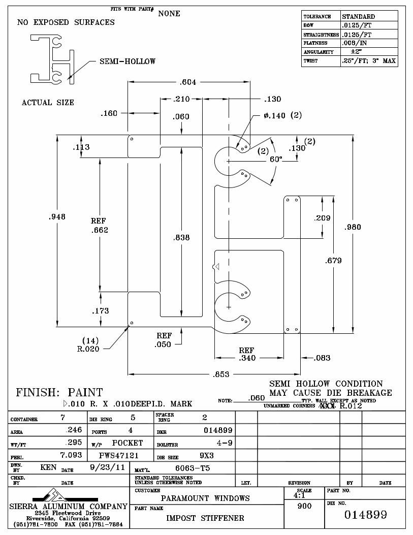
6100 SH WITH N/W 1-3/8'' FIN SET BACKDescription Supplier Part No Costs EA QuantityXO-SH MAIN FRAME Royal R1006 4SH VENT RAIL Royal R1078 2SH VENT STILE Royal R1807 1BOTTOM RAILS AND VENT STILE Royal R1079 2XO & SH LOCKSTILE Royal R1956 1GLAZING BEAD 3/4 SH/SL/PW Royal R1061 8SH VENT STOP AND FFPW FILLER Royal R1027 2IMPOST Royal KE-2541 1WEATHERSTRIPPING Royal .187x.240 inserted in extrusions by Royal as needed1/16 X 3/8 BLACK GLAZING TAPE Bron GL-NO516-WT 8Reinforcing / Lockstile Northstar NS-1314 1Reinforcing / Impost Sierra Aluminum 014899 1Sweep lock Ultra Hardware 97030 1Balance/Top and Bottom Guide Caldwell series 86 2Sash cam Caldwell 15P12 2Take-out clip Caldwell 15P22 2Setting blocks Bandlock BL-2434 1/8"X3/4" 16BAL/CAMS # 8 X 3/8" PH PN TSA ZINC US INDUSTRIAL 4Pal Lock # 8 X 3/4 " PH FL TSA BLK US INDUSTRIAL 2IMPOST # 8 X 1-1/2" PH PANCAKE WAFER TSA ZINC US INDUSTRIAL 4

C:\Users\emoser\AppData\Local\Temp\Temp2_vinyl window test submittal documents.zip\vinyl window test submittal documents\Window and Door BOM

emoser
Accepted
emoser
Accepted
emoser
Accepted
emoser
Line
emoser
Accepted
emoser
Accepted
emoser
Line
emoser
Accepted
emoser
Accepted
emoser
Accepted
emoser
B6000 Stamp
emoser
Line
emoser
Line
emoser
Line
emoser
Line
emoser
Line
emoser
Line
emoser
Line
emoser
Line
emoser
Line
emoser
Line
emoser
Line
emoser
Line
emoser
Line
emoser
Line
emoser
Line
emoser
Line
emoser
B6000 Stamp

PARAMOUNT WINDOWS

BILL OF MATERIALS

7100 SH WITH FLUSH FIN FOR RETRO FIT APPLICATIONDescription Supplier Part No Costs EA QuantityFLUSH FIN MAIN FRAME Royal R1744 4SH VENT RAIL Royal R1078 2SH VENT STILE Royal R1807 1BOTTOM RAILS AND VENT STILE Royal R1079 2XO & SH LOCKSTILE Royal R1956 1GLAZING BEAD 3/4 SH/SL/PW Royal R1061 8SH VENT STOP AND FFPW FILLER Royal R1027 2IMPOST Royal KE-2541 1WEATHERSTRIPPING Royal .187x.240 inserted in extrusions by Royal as needed1/16 X 3/8 BLACK GLAZING TAPE Bron GL-NO516-WT 8Reinforcing / Lockstile Northstar NS-1314 1Reinforcing / Impost Sierra Aluminum 014899 1Sweep lock Ultra Hardware 97030 1Balance/Top and Bottom Guide Caldwell series 86 2Sash cam Caldwell 15P12 2Take-out clip Caldwell 15P22 2Setting blocks Bandlock BL-2434 1/8"X3/4" 16BAL/CAMS # 8 X 3/8" PH PN TSA ZINC US INDUSTRIAL 4Pal Lock # 8 X 3/4 " PH FL TSA BLK US INDUSTRIAL 2IMPOST # 8 X 1-1/2" PH PANCAKE WAFER TSA ZINC US INDUSTRIAL 4

C:\Users\emoser\AppData\Local\Temp\Temp2_vinyl window test submittal documents.zip\vinyl window test submittal documents\Window and Door BOM

emoser
Accepted
emoser
Accepted
emoser
Accepted
emoser
Line
emoser
Accepted
emoser
Accepted
emoser
Line
emoser
Accepted
emoser
Accepted
emoser
Accepted
emoser
B6000 Stamp
emoser
Line
emoser
Line
emoser
Line
emoser
Line
emoser
Line
emoser
Line
emoser
Line
emoser
Line
emoser
Line
emoser
Line
emoser
Line
emoser
Line
emoser
Line
emoser
Line
emoser
Line
emoser
Line
emoser
Line
emoser
Line
emoser
Line
emoser
Line
emoser
Line
emoser
Line
emoser
B6000 Stamp
emoser
Accepted
emoser
B6000 Stamp
emoser
Accepted
emoser
B6000 Stamp
emoser
Accepted
emoser
B6000 Stamp
emoser
Accepted
emoser
B6000 Stamp
emoser
Accepted
emoser
B6000 Stamp
emoser
Accepted
emoser
B6000 Stamp
emoser
Accepted
emoser
B6000 Stamp
emoser
Accepted
emoser
B6000 Stamp
emoser
Accepted
emoser
B6000 Stamp
emoser
B6000 Stamp
emoser
B6000 Stamp

D–2

Muntin BarAluminum: Painted, Mill Finish, Clear & Color-InTM Anodized

Note: Available in pre-cut lengths and pre-notched; tutone and post-painted. Custom colors also available.

Please see terms & conditions of sale.Copyright © 2008 Allmetal, Inc.

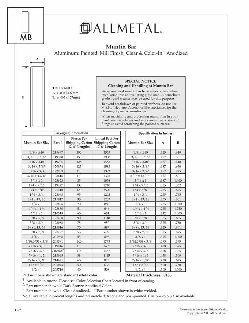
Part numbers shown are standard white color.† Available in tutone. Please see Color Selection Chart located in front of catalog.∆ Part number shown is Dark Bronze Anodized Color.* Part number shown is Clear Anodized. **Part number shown is white welded.

A

B

TOLERANCEA, ± .005 (.127mm)B, ± .005 (.127mm)

SPECIAL NOTICECleaning and Handling of Muntin Bar

We recommend muntin bar to be wiped clean before installation into an insulating glass unit. A household grade liquid cleaner may be used for this purpose.To avoid breakdown of painted surfaces, do not use M.E.K., Triethane, Alcohol or like substances for the cleaning of painted muntin bar.When machining and processing muntin bar in yourplant, keep saw tables and work areas free of saw cutfilings to avoid scratching the painted surfaces.

1/8 x .610 219697 200 25333/16 x 9/16† 119320 150 19003/16 x .610† 119705 125 15833/16 x 5/8† 120874 125 15833/16 x 3/4 122909 110 1393

3/16 x 13/16 123618 110 13933/16 x 1 123823 85 1076

1/4 x 9/16 119427 135 17101/4 x 5/8† 121410 120 15201/4 x 3/4 123063 95 1203

1/4 x 13/16 215017 95 12031/4 x 1 123836 70 887

1/4 x 1 1/4 123856 51 6465/16 x 1 210318 60 684

3/8 x 5/8 121468 90 11403/8 x 3/4 123088 75 950

3/8 x 13/16 215016 70 8873/8 x 7/8 123797 55 697

3/8 x 1 201968 55 6963/8(.375) x 3/8 205591 140 1773

7/16 x 3/8 119016 115 14577/16 x 3/8 216500** 115 14577/16 x 1/2 213045 88 11157/16 x 5/8 ∆ 214621 65 8231/2 x 3/4* 201043 50 633

1/2 x 1 203710 40 506

Packaging Information

Muntin Bar Size Part #Pieces Per

Shipping Carton12' 8" Lengths

Lineal Feet PerShipping Carton

12' 8" Lengths

Specification In Inches

Muntin Bar Size A B

1/8 x .610 .125 .6103/16 x 9/16† .187 .5513/16 x .610† .187 .6103/16 x 5/8† .187 .6303/16 x 3/4† .187 .775

3/16 x 13/16† .187 .8013/16 x 1 .187 1.000

1/4 x 9/16 .235 .5621/4 x 5/8 † .235 .6251/4 x 3/4 .235 .765

1/4 x 13/16 .235 .8011/4 x 1 .235 1.000

1/4 x 1 1/4 .235 1.2505/16 x 1 .312 1.000

3/8 x 5/8 † .325 .6253/8 x 3/4 .325 .750

3/8 x 13/16 .325 .8013/8 x 7/8 .325 .875

3/8 x 1 .325 1.0003/8(.375) x 3/8 .375 .375

7/16 x 3/8 .438 .3757/16 x 3/8 .438 .3757/16 x 1/2 .438 .5007/16 x 5/8 ∆ .438 .6251/2 x 3/4* .500 .750

1/2 x 1 .500 1.000Material thickness: .0185

D 1-22 Muntin Bar_pg order.qxp 11/18/08 11:03 AM Page D–2

emoser
Rectangle
emoser
B6000 Stamp

Recommended