382
GENERAL MATERIALS AND WORKMANSHIP SPECIFICATION VOLUME 2 ARCHITECTURAL WORKS ISSUE NO. 5b (FOR 3RS PROJECT ONLY) JULY 2019

GENERAL MATERIALS AND WORKMANSHIP
SPECIFICATION
VOLUME 2
ARCHITECTURAL WORKS
ISSUE NO. 5b (FOR 3RS PROJECT ONLY)
JULY 2019

[this page not used]

General Materials & Workmanship Specification - i - July 2019 Issue No. 5b – Table of Contents
GENERAL MATERIALS AND WORKMANSHIP SPECIFICATION
TABLE OF CONTENTS
VOLUME 1 CIVIL AND STRUCTURAL WORKS
Section 1 General – Civil and Structural Works
2 Temporary Works
3 Site Clearance and Demolition
4 Landscaping Works
5 Fencing
6 Drainage Works
7 Earthworks
8 Geotechnical Works
9 Carriageways: Sub-base Material and Bituminous Materials
10 Concrete Carriageways
11 Miscellaneous Roadworks
12 Traffic Signs, Road Markings and Road Studs
13 Work for Electrical and Mechanical Installations
14 Water Supply Pipeworks
15 Not Used
16 Not Used
17 Piling Works
18 Formwork and Finishes to Concrete
19 Steel Reinforcement
20 Concrete and Joints in Concrete
21 Prestressing
22 Steelwork
23 Bridgeworks
24 Water Retaining Structures
VOLUME 2 ARCHITECTURAL WORKS
Section 25 General – Architectural Works
26 Masonry and Blockwork
27 Waterproofing and Tanking
28 Roofing and Wall Cladding
29 Curtain Walling
30 Internal Cladding Systems
31 Carpentry and Joinery

General Materials & Workmanship Specification - ii - July 2019 Issue No. 5b – Table of Contents
VOLUME 2 ARCHITECTURAL WORKS (CONTINUED)
Section 32 Glazing, Glazed Screens, Balustrade and Handrails
33 Linings, Sheathings, Drywall Partitions and Toilet Cubicles
34 Suspended Ceilings
35 Architectural Metalwork (Including Metal Doors and Shutters)
36 Ironmongery
37 Hard Floor Finishes
38 Flexible Floor Finishes
39 Wall Finishes
40 Painting and Decoration
41 Fire Protection and Fire Stopping Systems
42 Signage
43 Blind System for Windows
43 A Single Girder Overhead Crane
44 Fall Arrest System
VOLUME 3 ELECTRICAL AND MECHANICAL WORKS
Section 44 Abbreviations, Standards and General – Electrical and Mechanical
45 Electrical Power Supply
46 Low Voltage Switchboards
47 Sub-Mains Electrical Distribution Equipment
48 Wiring and Cables
49 Cable Management Systems
50 Wiring Accessories and Miscellaneous Electrical Equipment
51 General Lighting Systems
52 Uninterruptible Power Supply System (UPS)
53 Motors
54 High Voltage Electrical Services
55 Not Used
56 Not Used
57 Earthing and Bonding System
58 Lightning Protection System
59 Electromagnetic Compatibility
60 Inspection, Testing and Commissioning - Electrical Services
61 Air Handling Units
62 Fan Coil Units
63 Fans

General Materials & Workmanship Specification - iii - July 2019 Issue No. 5b – Table of Contents
VOLUME 3 ELECTRICAL AND MECHANICAL WORKS (CONTINUED)
Section 64 Split Type Air Conditioning Unit
65 Window Type Air Conditioning Unit
66 Air Cooling Coils
67 Dampers and Air Volume Control Devices
68 Registers, Diffusers and Grilles
69 Air Filters
70 Ductwork and Fittings
71 Water Handling Equipment
72 Pipeworks, Fittings and Valves
73 Thermal Insulation
74 Sound Attenuator
75 Noise and Vibration Control
76 Electrical Equipment and Installation
77 Automatic Controls
78 Instruments
79 Testing, Inspection and Commissioning – Mechanical Services
80 Automatic Sprinkler System
81 Hydrant and Hose Reel System
82 Gaseous Fire Extinguishing System (FM200)
83 Fire Alarm and Detection System
84 Portable Hand Held Equipment
85 Visual Fire Alarm
86 Exist Sign and Directional Sign
87 Pipework, Valves and Fittings
88 Pumps and Tanks
89 Electrical Equipment and Installation
90 Inspection, Testing and Commissioning – Fire Services
91 Foul Water Disposal
92 Storm Water Disposal
93 Water Supply
94 Hot Water Supply System
95 Pipework, Fittings and Valves
96 Town Gas Reticulation
97 Pumps and Tank Level Controls
98 Electrical Equipment and Installation
99 Inspection, Testing and Commissioning – Hydraulic Services

General Materials & Workmanship Specification - iv - July 2019 Issue No. 5b – Table of Contents
VOLUME 3 ELECTRICAL AND MECHANICAL WORKS (CONTINUED)
Section 100 General Building Management System
101 Mechanical Building Management System
102 Voice and Data Cabling
103 Public Address System
104 Access Control System
105 Trunked Mobile Radio System
106 Closed Circuit Television System
107 Master Antenna Television (MATV)
108 Inspection, Testing and Commissioning Systems
109 Water Leakage Detection System
110 Not Used
111 Not Used
112 Not Used
113 Not Used
114 Not Used
115 Not Used
116 Not Used
117 Not Used
118 Not Used
119 Not Used
VOLUME 4 AIRFIELD WORKS
Section 120 General - Airfield Works
121 Airfield Ground Lighting System
122 Airport Lightning Warning System
123 Fixed Ground Power System
124 High Mast Lighting system
125 Pre-conditioned Air Supply Units
126 Aircraft Parking Aid System
127 Airfield Supervisory Control and Data Acquisition System
128 Aircraft Loading Bridges
129 Perimeter Fence Lighting System
130 Jet Blast Screens
131 Aviation Fuel Hydrant System
132 Airfield Pavement
133 Airfield Landscaping Works

General Materials & Workmanship Specification Issue No. 5b, Volume 2 – Architectural Works Table of Contents 1/5 July 2019
GENERAL MATERIALS AND WORKMANSHIP SPECIFICATION VOLUME 2 – ARCHITECTURAL WORKS SECTION 25 GENERAL – ARCHITECTURAL WORKS 25.1 Definition 25.2 Relevant Codes and Standards 25.3 Asset Numbering SECTION 26 MANSONRY AND BLOCKWORK 26.1 General 26.2 Not Used 26.3 Relevant Codes and Standards 26.4 Design and Performance Criteria 26.5 Materials 26.6 Submissions 26.7 Workmanship 26.8 Inspection, Testing and Commissioning SECTION 27 WATERPROOFING AND TANKING 27.1 General 27.2 Not Used 27.3 Relevant Codes and Standards 27.4 Design and Performance Criteria 27.5 Materials 27.6 Submissions 27.7 Workmanship 27.8 Inspection, Testing and Commissioning 27.9 Operations and Maintenance SECTION 28 ROOFING AND WALL CLADDING 28.1 General 28.2 Not Used 28.3 Relevant Codes and Standards 28.4 Design and Performance Criteria 28.5 Materials 28.6 Submissions 28.7 Workmanship 28.8 Inspection, Testing and Commissioning 28.9 Operations and Maintenance
General Materials & Workmanship Specification Issue No. 5b, Volume 2 – Architectural Works Table of Contents 2/5 July 2019
SECTION 29 CURTAIN WALLING 29.1 General 29.2 Not Used 29.3 Relevant Codes and Standards 29.4 Design and Performance Criteria 29.5 Materials 29.6 Submissions 29.7 Workmanship 29.8 Inspection, Testing and Commissioning 29.9 Operations and Maintenance SECTION 30 INTERNAL CLADDING SYSTEMS 30.1 General 30.2 Not Used 30.3 Relevant Codes and Standards 30.4 Design and Performance Criteria 30.5 Materials 30.6 Submissions 30.7 Workmanship 30.8 Inspection, Testing and Commissioning 30.9 Operations and Maintenance SECTION 31 CARPENTRY AND JOINERY 31.1 General 31.2 Not Used 31.3 Relevant Codes and Standards 31.4 Not Used 31.5 Materials 31.6 Submissions 31.7 Workmanship 31.8 Inspection, Testing and Commissioning SECTION 32 GLAZING, GLAZED SCREENS, BALUSTRADE AND HANDRAILS 32.1 General 32.2 Not Used 32.3 Relevant Codes and Standards 32.4 Design and Performance Criteria 32.5 Materials 32.6 Submissions 32.7 Workmanship 32.8 Inspection, Testing and Commissioning 32.9 Operations and Maintenance

General Materials & Workmanship Specification Issue No. 5b, Volume 2 – Architectural Works Table of Contents 3/5 July 2019
SECTION 33 LININGS, SHEATHINGS, DRYWALL PARTITIONS AND TOILET CUBICLES
33.1 General 33.2 Not Used 33.3 Relevant Codes and Standards 33.4 Design and Performance Criteria 33.5 Materials 33.6 Submissions 33.7 Workmanship 33.8 Inspection, Testing and Commissioning 33.9 Operations and Maintenance SECTION 34 SUSPENDED CEILINGS 34.1 General 34.2 Not Used 34.3 Relevant Codes and Standards 34.4 Design and Performance Criteria 34.5 Materials 34.6 Submissions 34.7 Workmanship 34.8 Inspection, Testing and Commissioning 34.9 Operations and Maintenance SECTION 35 ARCHITECTURAL METALWORK (INCLUDING METAL DOORS
AND SHUTTERS) 35.1 General 35.2 Not Used 35.3 Relevant Codes and Standards 35.4 Design and Performance Criteria 35.5 Materials 35.6 Submissions 35.7 Workmanship 35.8 Inspection, Testing and Commissioning 35.9 Operations and Maintenance SECTION 36 IRONMONGERY 36.1 General 36.2 Not Used 36.3 Relevant Codes and Standards 36.4 Design and Performance Criteria 36.5 Materials 36.6 Submissions 36.7 Workmanship 36.8 Inspection, Testing and Commissioning 36.9 Operations and Maintenance

General Materials & Workmanship Specification Issue No. 5b, Volume 2 – Architectural Works Table of Contents 4/5 July 2019
SECTION 37 HARD FLOOR FINISHES 37.1 General 37.2 Not Used 37.3 Relevant Codes and Standards 37.4 Design and Performance Criteria 37.5 Materials 37.6 Submissions 37.7 Workmanship 37.8 Inspection, Testing and Commissioning 37.9 Operations and Maintenance 37.10 Not Used SECTION 38 FLEXIBLE FLOOR FINISHES 38.1 General 38.2 Not Used 38.3 Relevant Codes and Standards 38.4 Design and Performance Criteria 38.5 Materials 38.6 Submissions 38.7 Workmanship 38.8 Inspection, Testing and Commissioning 38.9 Operations and Maintenance 38.10 Not Used SECTION 39 WALL FINISHES 39.1 General 39.2 Not Used 39.3 Relevant Codes and Standards 39.4 Design and Performance Criteria 39.5 Materials 39.6 Submissions 39.7 Workmanship 39.8 Inspection, Testing and Commissioning 39.9 Operations and Maintenance
SECTION 40 PAINTING AND DECORATION 40.1 General 40.2 Not Used 40.3 Relevant Codes and Standards 40.4 Design and Performance Criteria 40.5 Materials 40.6 Submissions 40.7 Workmanship 40.8 Inspection, Testing and Commissioning 40.9 Operations and Maintenance

General Materials & Workmanship Specification Issue No. 5b, Volume 2 – Architectural Works Table of Contents 5/5 July 2019
SECTION 41 FIRE PROTECTION AND FIRE STOPPING SYSTEMS 41.1 General 41.2 Not Used 41.3 Relevant Codes and Standards 41.4 Design and Performance Criteria 41.5 Materials 41.6 Submissions 41.7 Workmanship 41.8 Inspection, Testing and Commissioning
SECTION 42 SIGNAGE 42.1 General 42.2 Not Used 42.3 Relevant Codes and Standards 42.4 Design and Performance Criteria 42.5 Materials 42.6 Submissions 42.7 Workmanship 42.8 Inspection, Testing and Commissioning 42.9 Operations and Maintenance SECTION 43 BLIND SYSTEM FOR WINDOWS 43.1 Relevant Codes and Standards 43.2 Design and Performance Criteria 43.3 Submissions SECTION 43A SINGLE GIRDER OVERHEAD CRANE 43.1 Relevant Codes and Standards 43.2 Design and Performance Criteria 43.3 Submissions SECTION 44 FALL ARREST SYSTEM 44.1 Relevant Codes and Standards 44.2 Scope of Works 43.3 For Fixing to Concrete Structure

[this page not used]

General Materials & Workmanship Specification 1/4 July 2019 Issue No. 5b, Volume 2 – Architectural Works Section 25 – General – Architectural Works
SECTION 25 GENERAL – ARCHITECTURAL WORKS 25.1 DEFINITIONS & ABBREVIATIONS 25.1.1 Definitions
Words and expressions, to which meanings have been assigned in the General Conditions and General Specification, shall have the same meanings in this volume.
25.1.2 Abbreviations
Abbreviations in this volume shall have the following meanings:
AAMA American Architectural Manufacturer’s Association
ACI American Concrete Institution Standard
AISC American Institute of Steel Construction
ANSI American National Standards Institute
AS Australian Standard
ASTM American Society for Testing and Materials
BRE UK Building Research Establishment
BS British Standard
BSI British Standard Institution
CP British Standard Code of Practice
CS Construction Standard
DIN German Standard
DN Nominal size
EN European Standard
FGL Finished ground level, or finished level of permanent works
FSD Fire Services Department of Hong Kong
GEO Geotechnical Engineering Office, Civil Engineering Department
(Hong Kong Government)
HOKLAS Hong Kong Laboratory Accreditation Scheme
HSFG High strength friction grip
MR Moisture Resistant
NEN Nederlands Normalisatie-instituut
ISO International Organization for Standardization
OPC Ordinary Portland Cement
OSHA Occupational Safety and Health Administration
PD British Standard Public Document
PFA Pulverized fuel ash
PNAP Practice Note for Authorized Persons (current edition)
PPFA Portland pulverized fuel ash

General Materials & Workmanship Specification 2/4 July 2019 Issue No. 5b, Volume 2 – Architectural Works Section 25 – General – Architectural Works
RAL Colour Standard
RHPC Rapid hardening Portland cement
SIS Swedish Standard
SRPC Sulphate resisting Portland cement
25.2 RELEVANT CODES AND STANDARDS The Standards and Codes of Practice specified in this volume are for information only. The Contractor shall comply with the edition of the Standard or Code of Practice listed in the text when stated, or the latest edition when no edition is listed.
25.3 ASSET NUMBERING 25.3.1 Asset Code
(a) An asset can be a product, system, equipment, finish, etc. Each asset to be installed under the Contract shall be allocated a unique Asset Code. The Asset Code shall be adopted for easy identification in connection with the Works and recorded in asset data sheets to uniquely locate each asset and its parent system. Asset data for each asset or asset group to be submitted in the Operation and Maintenance Manual to the Project Manager for review without objection shall be identified with the unique Asset Code.
(b) The Asset Code shall be prepared by the Contractor and submitted to the
Project Manager for review without objection during the course of the Works. In the event of any ambiguity in the make up of the Asset Code, the Contractor shall request the specification/direction from the Project Manager.
(c) The Asset Code is made up of the following two parts, Asset Number and Location Code:
Asset Number
System / Sub-system / Component / Sub-component
The Asset Number defines what the system the asset belongs to and where in the hierarchy the asset belongs to. The hierarchy has a maximum of four levels and shall NOT contain location information unless agreed by the Project Manager. All four levels must be included and a “0” (zero) shall be used if any level is not used.
Location Code
Building / Level / Zone / Postcode or Facility
The Location Code describes the location of an asset. Various systems may use different location code types depending on whether the concerning system is internal or external. The hierarchy has a maximum of four levels and all four levels must be included and a “0” (zero) shall be used if any level is not used.

General Materials & Workmanship Specification 3/4 July 2019 Issue No. 5b, Volume 2 – Architectural Works Section 25 – General – Architectural Works
25.3.2 Facility Identification Labels
(a) The Contractor shall provide a label for assets. It shall be made of stainless steel or equivalent material, subject to review without objection by the Project Manager, capable of withstanding the environment in which the facility is located and retaining legibility for a minimum of ten years.
(b) Each label shall be attached to the facility at mounting positions, reviewed
without objection by the Project Manager. No adhesives shall be permitted.
(c) The Contractor shall submit a list of labels for assets to the Project Manager for review without objection.
(d) For Assets without the Colour Code, each label shall be as follows:
(i) Each label shall be engraved with the appropriate Asset Code and shall
be of adequate size, generally not less than 100mm long by 50mm high with a plate thickness of 2.5mm, to permit adequate spacing between characters and fixings to ensure legibility (Figure 25.5.1 refers);
(ii) All lettering used on labels shall be "Helvetica Bold" capitals and 10mm
high, unless otherwise specified;
(iii) Each label shall be attached to the facility as follows:
by M4 stainless steel self-tapping screws or similar fixings reviewed without objection by the Project Manager; or
by welding for metal facilities or similar fixings reviewed without objection by the Project Manager.
No adhesives shall be permitted.
(e) For Assets using the Colour Code, each label shall be as follows:
(i) Each label shall be engraved with the appropriate Asset Code below the
specified abbreviations in Chinese and English. It shall be of adequate size, generally not less than 90mm long by 50mm high with a plate thickness of 2.5mm, to permit adequate spacing between characters, letterings and fixings to ensure legibility (Figure 25.5.2 refers);
(ii) The abbreviations shall be placed above the Asset Code. The Chinese
abbreviation shall be placed to the left of the English abbreviation as shown in Figure 25.5.2;
(iii) All characters used for Chinese abbreviation on labels shall be of
appropriate font, subject to review without objection by the Project Manager, and 20mm high unless otherwise specified, using the colour code of BS5252F;
(iv) All lettering used for the English abbreviation on labels shall be
"Helvetica Bold" capitals and 10mm high, unless otherwise specified, using the colour code of BS5252F; and

General Materials & Workmanship Specification 4/4 July 2019 Issue No. 5b, Volume 2 – Architectural Works Section 25 – General – Architectural Works
(v) All lettering used for the Asset Code on labels shall be "Helvetica Bold" capitals and 10mm high, unless otherwise specified, using the colour code of BS5252F.
No adhesives shall be permitted.
(f) The Contractor shall submit one sample of each proposed label to the Project
Manager for review without objection.
(g) In the event the Works include replacing a facility, the Contractor shall fix to the replacement item a label bearing the new Asset Code, unless instructed otherwise by the Project Manager.
Figure 25.5.1 Sample of Label for Assets without Colour Code
Figure 25.5.2 Sample of Label for Assets with Colour Code
25.3.3 Asset Data Sheets
(a) The Contractor shall submit asset data for each asset or asset group with an Asset Code to the Project Manager for review as part of the O&M Manuals.
25.3.4 Practice of Labelling
Details of the exact descriptions of the label shall be agreed with the Project Manager prior to manufacture.
25.3.5 As-Constructed and BIM Submissions
The Contractor shall include asset codes in the As-Constructed Drawings and final BIM and submit the same to the Project Manager for review without objection.
Component Sub-
component
System Sub-system
General Materials & Workmanship Specification 1/20 July 2019 Issue No. 5b, Volume 2 – Architectural Works Section 26 – Masonry and Blockwork
SECTION 26 MASONRY AND BLOCKWORK 26.1 GENERAL
This section covers the use of stone, brickwork, blockwork and pre-cast concrete elements used in wall construction and the associated accessories needed. The materials specified below shall comply with the sections stated below, unless otherwise stated in this section:
(a) metalwork accessories refer to section 35;
(b) wall finishes refer to section 39;
(c) painting and decoration refer to section 40;
(d) cement refer to concrete section 20;
(e) water refer to concrete section 20; and
(f) steelwork supports refer to steelwork section 22.
26.2 NOT USED 26.3 RELEVANT CODES AND STANDARDS
The Standards and Codes of Practice specified in this section are listed below for information only. The Contractor shall comply with the edition of the Standard or Code of Practice listed in the text when stated, or the latest edition when no edition is listed. Where British Standards have been replaced by the new BS EN documents, the old BS number is retained in the text with the new BS EN number listed below.
BS 12 (replaced by BS EN 197-1)
Cement. Composition, specifications and conformity criteria for common cements
BS 476 Fire tests on building materials and structures
BS 812 Part 1 (replaced by BS EN 932)
Testing of Aggregates
BS 890 (replaced by BS EN 459-1)
Building lime. Definitions, specifications and conformity criteria
BS 1199 and 1200 (replaced by BS EN 13139)
Aggregates for mortar
BS 1217 Cast Stone
BS 1243 (replaced by BS EN 845-1+A1)
Specification for ancillary components for masonry. Wall ties, tension straps, hangers and brackets
General Materials & Workmanship Specification 2/20 July 2019 Issue No. 5b, Volume 2 – Architectural Works Section 26 – Masonry and Blockwork
BS 3921 (replaced by BS EN 771-1:2011+A1)
Specification for masonry units. Clay masonry units
BS 4551 (replaced by BS 4551+A2 & BS EN 1015)
Mortar. Methods of test for mortar and screed. Chemical analysis and physical testing
BS 4887 (replaced by BS EN 934-3+A1)
Admixtures for concrete, mortar and grout. Admixtures for masonry mortar. Definitions, requirements, conformity and marking and labelling
BS 5390 (replaced by BS EN 1996)
Eurocode 6. Design of masonry structures
BS 5492 (replaced by BS EN 13914-2 & BS 8481)
Design, preparation and application of external rendering and internal plastering. Internal plastering & Design, preparation and application of internal gypsum, cement, cement and lime plastering systems
BS 5628:Part 1 (replaced by BS EN 1996)
Eurocode 6. Design of masonry structures
BS 5977 Specification for Prefabricated Lintels
BS 6073 Part 1 (replaced by BS EN 771 + A1)
Specification for masonry units
BS 6398 Specification for Bitumen Damp Proof Courses for Masonry
BS 8000 Workmanship on Sites
BS 8215 Code of practice for design and installation of damp-proof courses
BS EN 845-1 + A1 Specification for ancillary components for masonry. Wall ties, tension straps, hangers and brackets
CP 111 and CP 121:Part 1 (withdrawn and substituted by BS EN 1996)
Eurocode 6. Design of masonry structures

General Materials & Workmanship Specification 3/20 July 2019 Issue No. 5b, Volume 2 – Architectural Works Section 26 – Masonry and Blockwork
26.4 DESIGN AND PERFORMANCE CRITERIA 26.4.1 Construction tolerances
The Contractor shall ensure that construction tolerances for masonry and blockwork are in accordance with BS 5628 Part 1.
26.4.2 Contractor’s design
(a) In the event that either or both of the following items are included in the Permanent Works:
(i) special pre-cast concrete features; and/or
(ii) stone cladding and special stone features,
(b) the Contractor shall design the features or cladding.
(c) The Contractor shall design the masonry and blockwork walls, including all
mullions, fixings, lintels, reinforcement, openings, holes, joints, movement joints and other features to complete the walls. The thickness of the walls shall not exceed the nominal sizes shown on the Employer’s Drawings. The design shall consider all load conditions. Mullions shall be designed so that the completed width, including any fire protection, is not greater than the blockwork or masonry width. Lintels shall be provided wherever the opening width exceeds the length of one brick or block.
(d) The Contractor shall ensure that its design takes fully into account and reflects all requirements for penetrations through blockwork or brickwork necessary to accommodate building services and systems, ducts, pipes, cables, containment and all related such equipment. The contractor shall ensure that requirements in this respect are full coordinated with the final resolved services and systems installation arrangements prepared by the services / systems installer(s) once the latter has been submitted and reviewed without objection by the Project Manager.
(e) The Contractor shall take into account all movements that may occur in the structure upon which the walls in question are founded and to which they abut and define explicitly upon its design / construction drawings the anticipated scale of movement allowed and the means of accomodating such allowances.
(f) The Contractor shall submit full details of the walling along with explicit / complete calculations defining all loading conditions and demonstrating that stability requirements are fully satisfied. The calculations shall be endorsed by an Independent Checking Engineer (ICE).
(g) The design of the works shall be in accordance with the recommendations of BS 5628 (Code of practice for the use of masonry) and for low-rise buildings in accordance with the recommendations of BS 8103 (Structural design of low-rise buildings).

General Materials & Workmanship Specification 4/20 July 2019 Issue No. 5b, Volume 2 – Architectural Works Section 26 – Masonry and Blockwork
(h) The works shall be detailed and installed to allow for and withstand all deflections and tolerances of the main structural elements under all design loads or combination of loads without damage or any reduction in the performance of the works.
(i) All fixings shall be capable of providing the correct degree of movement
required for the circumstances involved, to suit deflections specified and to provide adequate stability for the works.
(j) Movement joints shall be provided to accommodate all movements of the building structure and shall comply with BS 5628 (Code of practice for the use of masonry).
(k) Control joints shall be located at all junctions with adjoining work as indicated
on the Employer’s Drawings and in accordance with the recommendations of BS 5628 (Code of practice for the use of masonry).
(l) All block walls shall be built up with concrete or concrete solid block of not
less than 100mm thick unless reviewed without objection by the Project Manager for specific locations. No brick or hollow block wall shall be used as external wall to the building.
26.5 MATERIALS 26.5.1 Concrete Blockwork
(a) Concrete bricks and blocks: shall be manufactured to BS 6073 Part 1 and shall be supplied by a manufacturer previously reviewed without objection by the Project Manager. The average crushing strength of a randomly selected sample of 10 bricks or blocks shall be not less than 7 N/mm2 and a density not greater than 1,700 kg/m3. Blocks shall be either paint quality if they are to receive paint directly applied or standard quality for any other finish.
(b) Concrete bricks shall be of the same size as clay bricks. Concrete blocks shall be dense concrete of nominal size 190 mm x 390 mm (height x length); thicknesses shall be as shown on the Employer’s Drawings. Blocks shall be manufactured in accordance with BS 5628 Part 1: Normal category. Concrete bricks or blocks for fair face work shall be selected with regard to evenness, texture and sharpness of arises.
(c) Concrete hollow blocks: shall be manufactured to BS 6073 Part 1 and 2 and
shall be supplied by a manufacturer previously reviewed without objection by the Project Manager. Average crushing strength of a randomly selected sample of 10 blocks shall be not less than 7.0 N/mm2 calculated using the gross area. Blocks shall be either paint quality if they are to receive paint directly applied or standard quality for any other finish.

General Materials & Workmanship Specification 5/20 July 2019 Issue No. 5b, Volume 2 – Architectural Works Section 26 – Masonry and Blockwork
(d) Lightweight concrete blocks: shall be manufactured to BS 6073 Part 1 and 2 and shall be supplied by a manufacturer previously reviewed without objection by the Project Manager. The average crushing strength and blocks of a randomly selected sample of 10 blocks shall have a compressive strength of not less than 7 N/mm2 and a density not greater than 1,450 kg/m3. Blocks shall be either paint quality if they are to receive paint directly applied or standard quality for any other finish.
(e) Pre-cast concrete cills, lintels over door, window and duct openings, copings
and features: shall comply with the provisions of this section and Concrete section 20.
26.5.2 Natural or Cast Stone
(a) Stone shall be of consistent colour and free from defects and ferrous materials that will adversely affect strength or appearance. Stone shall comply with BS 5390.
(b) Cast stone shall also be manufactured in accordance with BS 1217:1997 and
shall have a compressive strength of not less than 25 N/mm2 and a typical density of 2,100 kg/m3 .
(c) This section covers all types of natural or cast stone including ashlar or
rubble walling laid dry or on a full even bed of cement mortar. 26.5.3 Glass Blocks
(a) Glass blocks shall be partially evacuated hollow units or solid glass units made of clear colourless glass with a polyvinyl butyral edge coating.
(b) Sizes and fire ratings shall be as specified with integral joint reinforcement.
(c) Glass block panels shall not be designed to support structural loads.
26.5.4 Reinforcement
(a) Brickwork and Blockwork walling shall be provided with bed joint reinforcement where and to the extent indicated on the Employer’s Drawings or, where the walling is to be designed by the Contractor, where such design dictates. In all such cases the reinforcement employed shall be of proprietary wire ladder type of the gauge indicated.
(b) As a minimum the reinforcement shall be provided in every sixth course of 75
mm gauge brickwork and ever second course in the case of 225 mm gauge blockwork.
(c) The reinforcement shall be manufactured from austenitic stainless steel in
both internal and external wall situations and in lengths not less than 2,500 mm. The width of the ladder reinforcement shall be o/a 40 mm less than the walling into which it is incorporated.

General Materials & Workmanship Specification 6/20 July 2019 Issue No. 5b, Volume 2 – Architectural Works Section 26 – Masonry and Blockwork
(d) The ladder reinforcement shall comprise two strands of wire running longitudinally each with a diameter of not less than 3 mm each and joined together with welded cross wires. Cross wires between the strands shall be at not greater than 450 mm c/s and of 3 mm diameter. If thicker wire is used for strands or cross wires it shall be flattened as part of the manufacturing process such that vertical thickness in the bed joints is not greater than 3 mm.
(e) Adjacent lengths of ladder reinforcement shall be lapped not less than 225
mm. Laps shall be staggered throughout the masonry. Laps shall be laid side by side and not stacked. The ladder reinforcement shall be cut and bent at corners and arranged to overlap.
26.5.5 Damp Proof Courses
(a) Damp proof courses shall be constructed of either:
(i) Bitumen damp proof courses complying with BS 6398; or
(ii) Polyethylene damp proof courses complying with BS 6515.
(b) The Contractor shall not use hessian-based types of bitumen damp proof courses.
26.5.6 Wall Ties (blockwork)
Ties for cavity walls shall be formed from 20 mmx3.2 mm flat, stainless steel flat section and shall be “vertical twist type” in compliance with BS 1243 and BSEN 845-1, except that the overall length of the ties shall be at least 100 mm longer than the width of the specified cavity. Ties between ends of walls and concrete shall be either: (a) lateral restraint ties for movement joints in internal skins of blockwork
consisting of austenitic stainless steel grade 316 flat ties at each alternate course, with one half of each length being de-bonded by wrapping with polythene sheet prior to building-in;
(b) 20 mm x 3 mm flat stainless steel by 350 mm long, flanged at both ends;
(c) strips of brickwork reinforcement 350 mm long of the following widths:
(i) For 100-105 mm walls, 60 mm;
(ii) For 200-225 mm walls, 110 mm; or
(d) lateral restraint ties at all junctions with concrete or structural steelwork, in
the vertical plane, with stainless steel fish tail type ties 2.5 mm thick, 25 mm wide, and 150 mm long (nominal dimensions) fixed to the structure at 400 mm centres (nominal) i.e. alternate block courses (this requirement does not apply to movement joints).
General Materials & Workmanship Specification 7/20 July 2019 Issue No. 5b, Volume 2 – Architectural Works Section 26 – Masonry and Blockwork
26.5.7 Wall Ties (Masonry)
(a) Ties between walls and concrete shall be galvanised mild steel in compliance with BS EN 845-1 + A1.
(b) Ties shall be not less than 40 mm wide, 3 mm thick and 150 mm long and
shall be flanged at both ends.
26.5.8 Sand
(a) Sand shall be clean, hard, durable crushed rock or clean sand complying with BS 1200, unless specified otherwise.
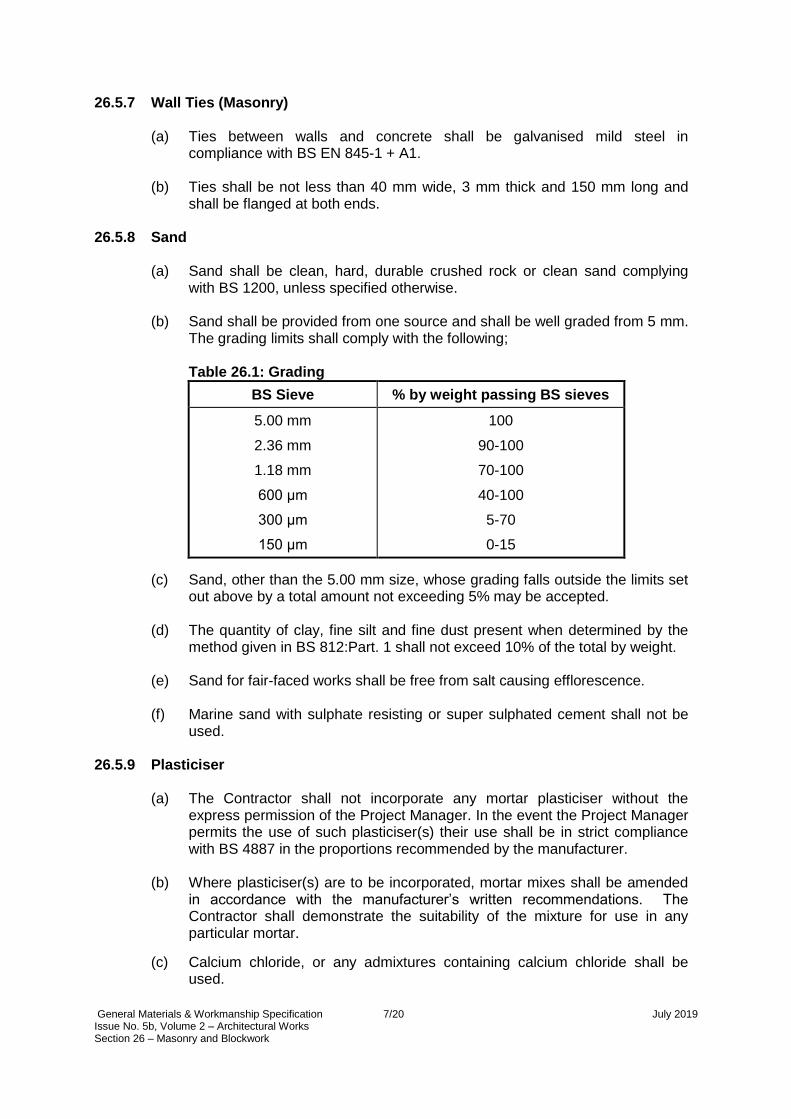
(b) Sand shall be provided from one source and shall be well graded from 5 mm.
The grading limits shall comply with the following; Table 26.1: Grading
BS Sieve % by weight passing BS sieves
5.00 mm
2.36 mm
1.18 mm
600 μm
300 μm
150 μm
100
90-100
70-100
40-100
5-70
0-15
(c) Sand, other than the 5.00 mm size, whose grading falls outside the limits set out above by a total amount not exceeding 5% may be accepted.
(d) The quantity of clay, fine silt and fine dust present when determined by the
method given in BS 812:Part. 1 shall not exceed 10% of the total by weight.
(e) Sand for fair-faced works shall be free from salt causing efflorescence.
(f) Marine sand with sulphate resisting or super sulphated cement shall not be used.
26.5.9 Plasticiser
(a) The Contractor shall not incorporate any mortar plasticiser without the express permission of the Project Manager. In the event the Project Manager permits the use of such plasticiser(s) their use shall be in strict compliance with BS 4887 in the proportions recommended by the manufacturer.
(b) Where plasticiser(s) are to be incorporated, mortar mixes shall be amended
in accordance with the manufacturer’s written recommendations. The Contractor shall demonstrate the suitability of the mixture for use in any particular mortar.
(c) Calcium chloride, or any admixtures containing calcium chloride shall be used.

General Materials & Workmanship Specification 8/20 July 2019 Issue No. 5b, Volume 2 – Architectural Works Section 26 – Masonry and Blockwork
26.5.10 Portland Cements
(a) The Contractor shall only use Portland cement, unless otherwise specified.
(b) All Portland cements shall conform to BS 12.
(c) Cement shall be delivered to Site in the original sealed bags of the manufacturer or in bulk containers which have been reviewed without objection by the Project Manager.
26.5.11 Lime
Lime shall conform to BS 890 and shall be hydrated lime of either Type (i), or (ii) or (iii).
26.5.12 Precast Concrete Lintels
Precast concrete lintels shall: (a) conform with the requirements of BS 5977: Part 1;
(b) incorporate continuous reinforcement running the length of the lintel;
(c) provide a minimum concrete cover to reinforcement of 25 mm; and
(d) have a minimum bearing of 150 mm at each end..
26.5.13 Movement Joints
The Contractor shall construct movement joints in a flexible, cellular polyethylene, cellular polyurethane or foam rubber joint filler that has been reviewed without objection by the Project Manager, as the blockwork proceeds, completely filling the joint for the width of the concrete blockwork.

General Materials & Workmanship Specification 9/20 July 2019 Issue No. 5b, Volume 2 – Architectural Works Section 26 – Masonry and Blockwork
26.6 SUBMISSIONS 26.6.1 Particulars of Masonry and Blockwork
The following particulars of the proposed masonry and blockwork shall be submitted to the Project Manager for review: (a) drawings showing the positions of all movement ,expansion,and control joints;
(b) drawings of all blockwork and masonry walls showing services openings and
holes which are to be designed by the contractor;
(c) blockwork and masonry drawings shall include any fire rated elements;
(d) details of the source, type and properties of all masonry and blockwork materials;
(e) details including test certificates and manufacturer’s compliance certfication
that confirm the blockwork and masonry achieves the fire resistance ratings specified in the Contract; and
(f) details including calculations of how tolerances will be achieved. 26.6.2 Samples
The following samples of the proposed materials shall be submitted to the Project Manager together with the particulars referred to above:
(a) each type of block, brick (4 no. of each type) and stone proposed and obtain
review without objection before placing orders with suppliers;
(b) 1 no. bag of lime, cement and sand;
(c) prepare sample panels of approximately 3 m2 of faced brickwork and fair faced brickwork or blockwork, including colour, finish, mortar type, pointing, and obtain review without objection before proceeding; and
(d) reinforcement, damp proof course materials, wall ties, plasticiser and any
other accessories specified. 26.6.3 Benchmarks and Samples
(a) The Contractor shall, following receipt of no objection from the Project Manager of relevant samples and prior to commencement of blockwork and masonry, construct an area of each type of blockwork and masonry work as a benchmark. The area shall be agreed with the Project Manager and shall, eventually, be incorporated into the Works. Upon a notice of no objection the benchmarks shall become the agreed standard to which all subsequent blockwork and masonry shall conform.
(b) In the event the Project Manager does not issue a notice of no objection for a
proposed benchmark, the Contractor shall demolish, remove and construct a new proposed benchmark before proceeding with any blockwork or masonry works.

General Materials & Workmanship Specification 10/20 July 2019 Issue No. 5b, Volume 2 – Architectural Works Section 26 – Masonry and Blockwork
26.7 WORKMANSHIP 26.7.1 Tolerances (Blockwork)
(a) The Contractor shall construct blockwork walls such that the dimension between any two points on the blockwork walls as built or between any point on the blockwork walls and any reference point agree, within the following tolerances, with the required dimension, whether shown on or calculable from the Employer’s Drawings.
Table 26.2: Maximum permitted/acceptable deviation of blockwork in
mm from required dimension
Up to 300 mm Over 300 mm to 2 m Over 2 m and above
3 5 10
Note that the figures given in the table above apply to such variables as:
(i) position relative to the nearest gridline;
(ii) plumb; including movement, construction and expansion joints;
(iii) cross section and other linear dimensions of the wall;
(iv) clear dimension between walls;
(v) distance of any corner from a plane containing the other three corners;
(vi) squareness of corners (the longer of two adjacent sides shall be
taken as the base line). Deviations from square calculated from length of the shorter side;
(vii) level, straightness and horizontal alignment.

General Materials & Workmanship Specification 11/20 July 2019 Issue No. 5b, Volume 2 – Architectural Works Section 26 – Masonry and Blockwork
26.7.2 Tolerances (Masonry)
All masonry shall comply with the following requirements: Table 26.3: Masonry Tolerances (mm)
Rubble
Walling
Ashlar
Walling
Position on plan 25 14
Length 25 15
Height 25 10
Level of bed joints (in any 5 m) 25 10
Straightness (in any 5 m) 25 15
Verticality (in any 3 m) 20 15
26.7.3 Accuracy
The Contractor shall: (a) lay bricks or blocks on a full bed of mortar with the joints filled solid to a
consistent thickness of 10 mm; (b) keep courses level and perpends vertically in line. Plumb quoins and other
angles as the work proceeds; and verify, that surfaces to receive the masonry and blockwork are within the tolerances as specified in this section and the Particular Technical Specification. Where an existing structure is found to be outside such tolerances, the Contractor shall take such measures to provide a suitable level bedding for the construction of blockwork.
26.7.4 Transportation and Handling
The Contractor shall: (a) transport stone with the minimum of handling; stack carefully in a vehicle with
packing pieces to prevent damage; (b) provide adequate lifting plant to unload and handle stones into position; (c) unload and handle masonry and blocks without soiling, chipping or
subjecting to other damage; and (d) not use damaged blocks.

General Materials & Workmanship Specification 12/20 July 2019 Issue No. 5b, Volume 2 – Architectural Works Section 26 – Masonry and Blockwork
26.7.5 Storing
The Contractor shall: (a) stack masonry and blocks on level hard-standings that provide protection
from damage and contamination; and (b) store stone in stacks on battens, and protect from rain.
26.7.6 Gauge Boxes
The Contractor shall measure mortar constituents by volume, using clean gauge boxes made to sizes to suit volumes required.
26.7.7 Mortar Proportions
(a) The Contractor shall mix constituents to the following proportions:
(i) cement/ mortar cement and sand 1: 3; and
(ii) cement/lime mortar cement, lime putty and sand 1:1:6 nominal to BS 5628 Part 3 designation iii.
(b) Proportions given shall be for dry sand. The Contractor shall allow for bulking.
26.7.8 Mixing
(a) The Contractor shall mix mortar by mechanical mixer or, where permitted by the Project Manager, by hand on a clean, close boarded platform.
(b) Mortar shall be mixed thoroughly but the Contractor shall ensure that mortar
containing plasticisers is not over mixed.
26.7.9 Mortars
The Contractor shall: (a) propose cement mortar for the following:
(i) work below damp proof course, including basement walls;
(ii) concrete blockwork not exceeding 150 mm;
(iii) load-bearing walls; and
(iv) pointing where directed and where bedding is of cement mortar; (b) propose cement/lime mortar for blockwork generally, except as specified; (c) use mortar within two hours of mixing at normal temperatures. Mortar may
be re-tempered to restore workability, but only within these time limits; (d) determine the required amount of water to achieve a workable mix;

General Materials & Workmanship Specification 13/20 July 2019 Issue No. 5b, Volume 2 – Architectural Works Section 26 – Masonry and Blockwork
(e) if pre-mixed mortars are proposed, submit the characteristics, product data, and testing criteria to the Project Manager for review; and
(f) submit details of the mortar consistency, water retention and air content for
this application to the Project Manager and obtain a notice of no objection prior to proceeding with the laying of blockwork.
26.7.10 Prevention of Drying Out of Mortar
During dry weather, wet bricks and blocks as necessary to prevent premature drying out of the mortar.
26.7.11 Wet weather
The Contractor shall, during wet weather, protect freshly laid masonry and blockwork at the completion of each day’s work or in heavy rain.
26.7.12 Protection
The Contractor shall: (a) protect newly erected stonework against inclement weather; (b) cover arrises projections and the like with adequate protection, firmly fixed;
and (c) clean off, rub down and leave stonework perfect immediately before
handover.
26.7.13 Uniformity
The Contractor shall distribute facing blocks and masonry for fair-faced work of varying colour evenly throughout the work so that no patches appear.
26.7.14 Blockwork Base Substrate
The Contractor shall lay blockwork only on structural slab or reinforced concrete plinths. Where a screed exists, the Contractor shall remove the screed locally down to structural slab level before constructing the blockwork.
26.7.15 Work Above Another
The Contractor shall carry up work with no portion more than 900 mm above another at any time, racking back between levels.
26.7.16 Quoins and Jambs
Quoins and jambs shall be plumbed as the blockwork proceeds. The head of all walls shall be laid level.
General Materials & Workmanship Specification 14/20 July 2019 Issue No. 5b, Volume 2 – Architectural Works Section 26 – Masonry and Blockwork
26.7.17 Blockwork Panels
(a) The Contractor shall divide blockwork walls into panels separated by control joints. The control joints shall be located such that the length of each blockwork panel is neither greater than 6m nor greater than twice the panel height.
(b) Control joints shall coincide with structural support work where possible and
shall utilise stainless steel proprietary sleeved tie anchors.
26.7.18 Control Joints
The Contractor shall construct control joints with a continuous nominal width of 12 mm filled with weak mortar, raked out to a depth of not less than 20 mm, and finished with fire resistant mastic.
26.7.19 Expansion Joints
The Contractor shall construct expansion joints at location as indicated on the Employer’s Drawings. The expansion joints shall be incombustible, flexible fire barriers in compliance with BS 476 Part: 20 1987, compressible to accommodate all structural tolerances and which achieves the same fire rating as the wall.
26.7.20 Cavity Walling
The Contractor shall: (a) build cavity walls with cavities of the widths and walling of the thickness as
specified. (b) bond the two thickness of walling together with ties spaced 900 mm apart
horizontally and 320 mm vertically, staggered, and with additional ties at reveals and opening; carefully position ties so that they fall toward the outer thickness of the wall;
(c) keep cavity clean by means of lifting battens; and (d) leave openings at the base of the cavity to facilitate clearing out on
completion and subsequently close up to match the surrounding work.
26.7.21 Bonding
The Contractor shall: (a) lay blockwork in stretcher bond, unless otherwise specified; (b) lay blocks throughout the work with the perpends in any course not less than
a quarter of a block from those in the course below; and (c) lay fair-faced blockwork with joints to an even and regular pattern.

General Materials & Workmanship Specification 15/20 July 2019 Issue No. 5b, Volume 2 – Architectural Works Section 26 – Masonry and Blockwork
26.7.22 Finishing of Joints
The Contractor shall: (a) strike off joints not visible in the finished work as the work proceeds; fill joints
in fair-faced work as the work proceeds to provide a smooth surface flush with the brick or block face;
(b) finish joints in faced brickwork with either a trowelled weathered joint as the
work proceeds, or rake out to a depth of 10 mm as the work proceeds and point with a weathered joint on completion; rake out joints to a depth of 10 mm in brickwork to provide key for plaster or other wet applied finishes.
26.7.23 Damp Proof Course
The Contractor shall: (a) flush up blockwork to form a level and even bed with mortar used in the
general brickwork to receive the horizontal damp proof course; (b) lay damp proof course in continuous strip with 150 mm laps at end of length
and at returns, and complete mortar joint to normal thickness;and (c) lay damp proof courses in accordance with BS 8215.
26.7.24 Wedging and Pinning
The Contractor shall pin up and wedge masonry and blockwork to structural soffits, and fill solid with mortar.
26.7.25 Building In The Contractor shall build in lintels and bed solid door and window frames and the like with mortar similar to that of adjacent walls.
26.7.26 Holes and Chases
The Contractor shall: (a) leave, form or cut chases, holes, recesses and reveals in walls to receive
frames, rainwater or other pipes, conduits, electric cables, sleeves and the like as required; and
(b) subsequently make good with mortar similar to that of adjacent walls.
26.7.27 Cutting of Blocks
(a) Where blocks are cut, the Contractor shall make the gaps between concrete
and blockwork as indicated on the Employer’s Drawings. Blocks shall be cut only by power driven masonry saw, wet hosed down to remove any slurry and have excess moisture removed prior to laying. No cut faces shall be exposed in the Works unless agreed with the Project Manager.

General Materials & Workmanship Specification 16/20 July 2019 Issue No. 5b, Volume 2 – Architectural Works Section 26 – Masonry and Blockwork
(b) The Contractor shall leave, form or cut chases and reveals in walls to receive frames, rainwater or other pipes and electrical conduits such that these can be concealed from view beneath wall finishes unless the Employers drawings explicitly state, for any particular area, that such services may run exposed upon the wall surface. Chasing in walls shall be undertaken with precision to ensure that width and depth are the minimum required to allow the services to be accommodated but without adversely affecting the structural stability of the walls in which they are located.
(c) After services are installed the Contractor shall return to the walling and
make good flush to the wall face using cement mortar of similar composition to that used for wall construction. Such making good shall be allowed to thoroughly dry out before application of any subsequent wall finishing
26.7.28 Raking Out and Pointing Flashings (Blockwork)
The Contractor shall rake out joints to a depth of 25 mm for turn-in of flashings or skirting; point flashings and skirting in mortar similar to that in adjacent walls.
26.7.29 Acoustic Performance Requirements
The Contractor shall: (a) ensure that all blockwork walls achieve as a minimum the sound reduction
index to which they have been designed (weighted sound reduction); and (b) ensure that all mortar joints are filled with mortar to full depth, except where
indicated on Employer’s Drawings. 26.7.30 Service Openings
The Contractor shall: (a) where areas of blockwork incorporate service openings, treat the reveal
edges as fair-faced; and (b) after the installation of all services, maintain the total performance and
integrity of the walls and partitions. 26.7.31 Pointing masonry
The Contractor shall: (a) rake out joints to a depth of 15 mm as the work proceeds; and (b) point in cement mortar with a flush, weathered or recessed joint as required
on completion.

General Materials & Workmanship Specification 17/20 July 2019 Issue No. 5b, Volume 2 – Architectural Works Section 26 – Masonry and Blockwork
26.7.32 Preparation of Stone The Contractor shall: (a) work the exposed and joint faces of each stone to a square and true plane
surfaces, free from hollow or rough areas;
(b) Finish exposed faces to a finely squared dressed surface. Stones shall be not less than 300 mm high; and
(c) mark each stone clearly to indicate its position into finished work.
26.7.33 Laying and Jointing Stonework
The Contractor shall: (a) lay stones on a full, even bed of mortar composed of cement and fine
crushed stone 1:3, with all joints filled of consistent width and between 15 and 5 mm wide depending on the walling type;
(b) lay stones to bond together throughout the wall, and to backing using
projecting bonding stones.
26.7.34 Stonework Built Against Concrete The Contractor shall: (a) for stone walling, cast in or build in for a depth of 100 mm at least 5 wall ties
per square metre to project 75 mm into the stone walling. Bed facing against backing in mortar;
(b) at junctions of stone walling with concrete or blockwork, cast in or build ties
at 450 mm (minimum) centres vertically, to project 250 mm into stone walling. 26.7.35 Glass Block Panels
The Contractor shall:
(a) paint all sides of structural opening to receive glass block panels with two
coats of bituminous paint; (b) lay blocks in cement/lime mortar and point both sides; provide 12 mm
clearance at jambs and head of panels; fill gap with movement joint filler and seal both sides;
(c) build in strips of blockwork reinforcement 64 mm wide at every fourth course;
carry ends of strips across the clearance gap and build into or secure to jambs of opening; use proprietary fixing components supplied by glass block manufacturer and follow all fixing details recommended by the manufacturer.

General Materials & Workmanship Specification 18/20 July 2019 Issue No. 5b, Volume 2 – Architectural Works Section 26 – Masonry and Blockwork
26.7.36 Alterations to Existing Masonry and Blockwork The Contractor shall: (a) arrange all new courses to line up with existing work; (b) bond all new walls to existing by cutting pockets not less than 100mm deep,
the full thickness of the new wall and every block/ masonry course; bond new walling into pockets with all voids filled solid;
(c) except where a straight vertical joint is specified, tooth bond every course for
new and existing facework in the same plane to give a continuous appearance;
(d) where new lintels or walling are used to support existing structure,
completely fill the top joint with semi-dry mortar, hard packed and well rammed, to ensure full load transfer after removal of temporary supports;
(e) cut out and replace cracked blocks or masonry in existing facework with
matching materials and bedded in the specified mortar; (f) re-pointing: carefully rake out existing joints by hand to form a square recess
of 15-20 mm depth; and (g) remove dust, lightly wet and neatly point in the specified mortar and profile in
a continuous operation. 26.7.37 Steelwork Supports to Blockwork and Masonry Walling
All seelwork supports to walling shall comply with Section 22 (steelwork), lateral restraints tying the supports in to the walling shall be provided in accordance with 26.5.6 of this Section.
26.7.38 Walls Below Slabs and Beams
The Contractor shall detail the mullions and blockwork or masonry to allow for the deflection of slabs and beams above walls. The joint between the slab or beam and the top of the wall shall be a minimum of 20 mm and shall be filled with a suitable flexible sealant or flexible fire rated sealant.

General Materials & Workmanship Specification 19/20 July 2019 Issue No. 5b, Volume 2 – Architectural Works Section 26 – Masonry and Blockwork
26.8 INSPECTION, TESTING AND COMMISSIONING 26.8.1 Mortar Testing
The Contractor shall: (a) carry out all tests on wet or hardened mortar samples in accordance with BS
4551; (b) take samples at the point of mixing or use. The frequency of sampling shall
not be less than that specified in Appendix A.1 of BS 5628:Part 1; (c) perform additional tests and sampling if the mortar does not comply with this
Specification. Subject to the test results, adjust and test the specified nominal mix proportions;
(d) test half of the samples at 7 days, the remainder at 28 days. The 28 days
crushing strength of the cubes shall not be less than 3.6 N/mm2 for the preliminary test and 2.5 N/mm2 for the work test;
(e) test the consistency of mortar for conformance with the Contractor’s
recommendations which have received a notice of no objection from the Project Manager using the test procedure described in clause 10 of BS 4551;
(f) test the water retention of mortar for conformance with the Contractor’s
recommendations which have received a notice of no objection from the Project Manager using the test procedure described in clause 11 of BS 4551;
(g) test the air control of mortar for conformance with the Contractor’s
recommendations which have received a notice of no objection from the Project Manager using the test procedure described in clause 13 of BS 4551.
26.8.2 Blockwork Testing
(a) The Contractor shall submit his selected sources of blockwork to the Project Manager for review without objection together with certificates of recent tests carried out in accordance with the relevant British Standards for all sources giving the following information:
(i) compressive strength;
(ii) absorption percentage;
(iii) soluble salt content;
(iv) drying shrinkage or moisture expansion; and
(v) density and tolerance in dimensions.
(b) The Contractor shall take a sample of 4 blocks per 1,000 for assessment of
drying shrinkage in accordance with BS 6073 Part 1. These sample blocks
shall be taken from the centre of the stacks. The drying shrinkage shall be 0.06%.

General Materials & Workmanship Specification 20/20 July 2019 Issue No. 5b, Volume 2 – Architectural Works Section 26 – Masonry and Blockwork
26.8.3 Testing Lintels
The Contractor shall test pre-cast concrete lintels using the procedure described in BS 5977 part 2 appendix B;
26.8.4 Fire resistance integrity
The Contractor shall construct blockwork walls in accordance with the Specifications and achieve the fire resistance as specified on the Employer’s Drawings.

General Materials & Workmanship Specification Issue No. 5b, Volume 2 – Architectural Works 1/7 July 2019 Section 27 – Waterproofing and Tanking
SECTION 27 WATERPROOFING AND TANKING
27.1 GENERAL
The materials specified below shall comply with the sections stated, unless otherwise stated in this section: (a) concrete and joints in concrete refer to section 20;
(b) water retaining structures refer to section 24; and
(c) roofing refer to section 28.
27.2 NOT USED
27.3 RELEVANT CODES AND STANDARDS
The Standards and Codes of Practice specified in this section are listed below for information only. The Contractor shall comply with the edition of the Standard or Code of Practice listed in the text when stated, or the latest edition when no edition is listed. Where British Standards have been replaced by the new BS EN documents, the old BS number is retained in the text with the new BS EN number listed below.
BS 410 (replaced by BS ISO 3310)
Test sieves
BS 5284 Sampling and testing mastic asphalt and pitch mastic used in building
BS 6925 Mastic asphalt for building
BS 1199 and 1200 (replaced by BS EN 13139)
Aggregates for mortar
BS 8000:Part 4 Code of practice for waterproofing
BS 8102 Code of Practice for Protection of Below Ground Structures Against Water from the Ground
27.4 DESIGN AND PERFORMANCE CRITERIA
(a) The Contractor shall design tanking in compliance with BS 8102 - protection of
structures against water from the ground.
(b) For sheet membrane tanking, the work shall be executed by the manufacturer’s approved specialist contractor.
(c) Before commencing the Works, the Contractor must demonstrate on Site that
all adhesives and materials are fully compatible

General Materials & Workmanship Specification Issue No. 5b, Volume 2 – Architectural Works 2/7 July 2019 Section 27 – Waterproofing and Tanking
27.5 MATERIALS
27.5.1 Mastic Asphalt
Mastic asphalt for tanking shall comply with type T 1097 to BS 6925 (lime stone aggregate) or type T1418 to BS 6577 (natural rock asphalt aggregate). All mastic asphalt blocks delivered to Site shall bear legible markings including: (a) the name or trade mark of the manufacturer;
(b) the number and date of British Standard; and
(c) the type of number, e.g. TI097 to BS 6925: 1985. 27.5.2 Flexible Sheet Membrane
(a) Proprietary flexible sheet membrane shall be capable of accommodating unanticipated cracks of up to 0.6 mm wide without losing its waterproofing properties.
(b) The properties of the membrane in lap shear and lap peel shall not be less
than 110 KN/m2 and 3.3 KN/m respectively when installed on site.
(c) Surface treatments of liquid membrane of any kind are not acceptable. This sub-section covers single ply polyester plasticized plastic membranes which shall be strictly in accordance with the manufacturer’s recommendations.
(d) Certificates together with complete test reports to substantiate that the
materials supplied meet the requirements specified shall be submitted when the material is delivered to Site.
27.5.3 Other Proprietary Concrete Sealers
(a) This section covers the use of proprietary deep penetrating concrete sealers.
They shall not be surface treatments and shall be supplied and applied strictly in accordance with the manufacturer’s recommendations.
(b) The Contractor shall submit certificates together with complete test reports to substantiate compliances of the materials to the Project Manager when the material is delivered to Site.
27.6 SUBMISSIONS
27.6.1 Particulars of Waterproofing and Tanking Systems
The following particulars of the proposed waterproofing and tanking systems shall be submitted to the Project Manager for review without objection: (a) Contractor’s Drawings showing construction details including those at angles,
internal and external corners, construction joints, pipe intrusions and outlets;
(b) details of the source, type and properties of the materials proposed;
(c) certificates together with complete test reports to substantiate that the materials supplied comply with the Specification shall be submitted to the Project Manager when the material is delivered to Site.

General Materials & Workmanship Specification Issue No. 5b, Volume 2 – Architectural Works 3/7 July 2019 Section 27 – Waterproofing and Tanking
27.7 WORKMANSHIP
27.7.1 Workmanship for All Waterproofing and Tanking
The Works shall be carried out in accordance with BS 8102 and BS 8000: Part 4. Particular attention is drawn to the followings before installation: (a) A competent representative from the Contractor shall supervise the Works.
Inspections shall be carried out and written approval given by this representative for each and every stage of the work from the surface preparation to the completion of the protective coating. Such written approvals and completed stages shall be presented at the completion of each stage to the Project Manager for review without objection prior to the Contractor commencing the next stage.
(b) The Works shall only be carried out after the concrete has been curing for at
least 28 days. 27.7.2 Surface Preparation
(a) Surfaces to which tanking is to be applied shall be level and free from irregularities such as ridges, dips, fins and concrete or mortar droppings. The horizontal surfaces of the concrete shall be given a wood-floated finish and be laid flat and true to allow the specified thickness of mastic asphalt to be applied uniformly.
(b) Surfaces to which sheet membrane is to be applied shall be smooth, level and
free from all irregularities such as ridges, dips, fins and concrete or mortar droppings. The horizontal surfaces of the concrete shall be given a steel-floated finish and be laid flat and true to allow the membrane to be applied uniformly.
(c) Where vertical concrete is very smooth and in order to provide a satisfactory
key for the mastic asphalt or a sheet membrane, the Contractor shall remove the surface laitance by wire brushing and apply an approved proprietary high bond primer. Excessive mould oil in the vertical form shall not be used.

General Materials & Workmanship Specification Issue No. 5b, Volume 2 – Architectural Works 4/7 July 2019 Section 27 – Waterproofing and Tanking
27.7.3 Remelting Mastic Asphalt on Site
The Contractor shall:
(a) break the blocks into pieces of suitable size, carefully stack in an cauldron or mechanical mixer, previously reviewed without objection by the Project Manager, and gradually heat to a temperature at no time exceeding 230oC;
(b) whilst heating, agitate the asphalt continuously to prevent local over-heating;
(c) remove the asphalt from the cauldron or mixer by means of buckets, which
have been coated with a fine inert dust or cement. Ashes or oil shall not be used for this purpose;
(d) check continuously with suitable thermometers to ensure that the asphalt is
heated to the correct temperature; and
(e) take samples during the remelting process and perform the composition and the hardness number tests as stated in the Inspection Testing and Commissioning section of this Specification.
27.7.4 Laying of Mastic Asphalt
(a) On horizontal surfaces, mastic asphalt shall be laid in three coats to a total thickness of 30 mm.
(b) On vertical surfaces, mastic asphalt shall be applied in three coats to a total
thickness of not less than 20 mm taken to a height of at least 150 mm above ground level.
(c) An angle fillet not less than 50 mm wide shall be applied in two coats at the
junction of two planes forming an internal angle.
(d) Joints in successive coats of mastic asphalt shall be staggered at least 150 mm for horizontal work and 75 mm for vertical work. The top of vertical mastic asphalt shall be tucked into a chase not less than 25 mm x 25 mm unless the mastic asphalt is being continued horizontally.
27.7.5 Laying of Membrane
(a) Proprietary flexible sheet membrane shall be primed, laid, lapped and finished in strict compliance with the manufacturer's recommendation.
(b) No work shall be undertaken when the surface moisture exceeds the
permissible content recommended by manufacturer, as tested by the moisture testing equipment on Site.
(c) Adhesive shall be spread in a progressive manner to accord with laying the
membrane. Adhesive that sets prior to laying the membrane shall be forbidden.
(d) The Contractor shall keep a daily record of the adhesive used and check
against the agreed spreading rate of membrane. Bubbles formed in the membrane must be made good in accordance with the manufacturer’s technical literature.

General Materials & Workmanship Specification Issue No. 5b, Volume 2 – Architectural Works 5/7 July 2019 Section 27 – Waterproofing and Tanking
27.7.6 Protection The Contractor shall:
(a) Notwithstanding the Contractor’s obligations under GCC Section 20 (Care of
the Works), apply protection within 2 working days on completion of each section of the Works;
(b) protect horizontal work with a screed of cement and sand mortar 50 mm in
thickness. For ease of placing, this horizontal protection coating shall be very workable. Slump of less than 100 mm is not recommended. Temporary protection for the lapping area at the end of a working day shall be strictly in accordance with the manufacturer's recommendation;
(c) protect vertical work against damage by the erection of a masonry wall or
protective boarding constructed of ribbed polypropylene or bitumen impregnated wood chip rigid panels;
(d) in cases where it is not possible to provide the protection described in (b) and (c) above, provide a proprietary protection system recommended by the waterproofing manufacturer and compatible with the following finishes. The protection system shall be submitted to the Project Manager for review without objection prior to use, and shall be installed strictly in accordance with the manufacturer’s recommendations.
General Materials & Workmanship Specification Issue No. 5b, Volume 2 – Architectural Works 6/7 July 2019 Section 27 – Waterproofing and Tanking
27.8 INSPECTION TESTING AND COMMISIONING
27.8.1 Testing of Mastic Asphalt
(a) Sampling and testing of mastic asphalt for composition and hardness number shall be carried out in accordance with BS 5284.
(b) The Contractor shall prepare a bulk sample as stated below selected at
random from not less than 8 blocks, breaking them and taking portions from the inner part of each block and deliver samples to the HK Government Laboratory for testing. The test results shall comply with table 27.1 below.
27.8.2 Sampling During Laying of Mastic Asphalt
(a) During laying, at least one sample shall be taken from the cauldron or mixer per day for control test.
(b) Sample prepared for test shall not be less than 6 kg by taking three
increments, from the discharge of the mixer or from the middle of the cauldrons when approximately half of the charge remains. In the case of hand stirred cauldrons the molten material shall be thoroughly stirred immediately prior to the samples being taken. Thoroughly mix the three increments together in a clean wide-mouthed galvanized-iron bucket of approximate size 250 mm diameter x 150 mm.
(c) The Contractor shall prepare two specimens for hardness number tests from
the thoroughly mixed bulk sample as follows:
(d) pour the mastic into two hardness moulds to a level slightly higher than the edge of the moulds;
(e) tap with a spatula on the edge of the moulds for about 3 minutes to level the
mastic and drive out entrapped air from the specimen; and
(f) level off the surface with the spatula.
(g) The moulds and spatula should be warmed before use.
(h) The Contractor shall pour bulk sample for testing composition into a wooden mould size 300 mm x 300 mm x 25 mm deep.
(i) The composition and hardness number of the samples shall comply with
Tables 27.1 and 27.2 below. If the sample fails to comply, the work on Site represented by the sample should be completely removed and redone.

General Materials & Workmanship Specification Issue No. 5b, Volume 2 – Architectural Works 7/7 July 2019 Section 27 – Waterproofing and Tanking
Table 27.1: Composition by Analysis of Mastic Asphalt: Type T1097 and T1418
Property % by mass of mastic asphalt
T1097 T1418
Grading of mineral aggregate using BS410 test sieves
Min. Max. Min. Max.
Retained on 3.35 mm mesh 0 2 0 0
Passing 3.35 mm mesh, retained on 600 μm mesh
4 17 0 10
Passing 600μm mesh, retained on 212 μm mesh 8 26 5 20
Passing 212 μm mesh, retained on75 μm mesh 8 26 5 20
Passing 75 μm mesh 28 50 45 65
Soluble bitumen 12 15 17* 20*
* 13% min and 16% max for Swiss natural rock asphalt Table 27.2: Hardness Number for Mastic Asphalt at 25 deg. C
Property T1097 T1418
Re melted on site/laboratory
Not less than 40 Not less than 90 Not more than 150
At the time of laying Not less than 40 Not less than 60 Not more than 150
27.8.3 Testing of Sheet Membrane
Sampling and testing of sheet membrane shall be agreed with the Project Manager and the results shall comply with the properties given in section 27.5.2.
27.8.4 Testing of All Waterproofing and Tanking (a) All surfaces of waterproofing and tanking shall be 100% visually inspected.
(b) All tanked volumes and all horizontal waterproofing surfaces shall be flood
tested for a minimum of 24 hours. The water level of the test shall to be the full height of the tanking, and for waterproofing a minimum of 75mm above the surface being tested. Any temporary bunds to contain the test shall be positioned so that joints in waterproofing are completely within the tested area.
(c) On completion of the flood test, the Contractor shall immediately carry out an
infrared thermographic survey, or other method agreed with the Project Manager, to demonstrate that there has been no leakage.
27.9 OPERATIONS AND MAINTENANCE
27.9.1 Operation and Maintenance Manual
The Contractor shall provide an Operation and Maintenance Manual including, but not limited to, particulars of waterproofing systems, material manufacturers, movement joints, repair methods and maintenance requirements.

[this page not used]

General Materials & Workmanship Specification Issue No. 5b, Volume 2 – Architectural Works 1/14 July 2019 Section 28 – Roofing & Wall Cladding
SECTION 28 ROOFING AND WALL CLADDING 28.1 GENERAL
The materials specified below shall comply with the sections stated, unless otherwise stated in this section:
(a) steelwork shall refer to section 22;
(b) waterproofing and tanking refer to section 27; and
(c) curtain walling refer to section 29.
28.2 NOT USED
28.3 RELEVANT CODES AND STANDARDS
The Standards and Codes of Practice specified in this section are listed below for information only. The Contractor shall comply with the edition of the Standard or Code of Practice listed in the text when stated, or the latest edition when no edition is listed. Where British Standards have been replaced by the new BS EN documents, the old BS number is retained in the text with the new BS EN number listed below.
BS 476: Parts 3 and 7 Fire tests on building materials and structures
BS 747 (replaced by BS EN 13707)
Flexible sheets for waterproofing. Reinforced bitumen sheets for roof waterproofing. Definitions and characteristics
BS 1178 (replaced by BS EN 12588)
Lead and lead alloys. Rolled lead sheet for building purposes
BS 1470 (replaced by BS EN 515 & BS EN 485 & BS EN 573)
Aluminium and aluminium alloys
BS 2870 (replaced by BS EN 1652 & BS EN 1653 & BS EN 1654 & BS EN 1172)
Copper and copper alloys
BS 3083 Hot dipped zinc coated corrugated steel sheets or general purposes
BS 3382 (replaced by BS 7371-12)
Coatings on metal fasteners. Requirements for imperial fasteners
BS 3532 Method of specifying unsaturated polyester resin system
BS 3690 (replaced by BS EN 12591 & BS EN 13924-1)
Bitumen and bituminous binders
BS 4868 Profiled aluminium sheet for building

General Materials & Workmanship Specification Issue No. 5b, Volume 2 – Architectural Works 2/14 July 2019 Section 28 – Roofing & Wall Cladding
BS 5427 + A1 Code of practice for performance and loading criteria for profiled sheeting in building
CP 143 Sheet roof and all coverings
CP 144:Part 3 (replaced by BS 8217)
Reinforced bitumen membranes for roofing. Code of practice
BS EN 505 Roofing products from metal sheets-steel sheet
BS EN 507 Roofing products from metal sheets-aluminium sheets
BS EN 508 Specification for self-supporting products of steel, aluminium or stainless steel
28.4 DESIGN AND PERFORMANCE CRITERIA
28.4.1 Proprietary Roofing Systems
(a) Proprietary roofing systems shall be designed and laid by specialist contractors listed on the HK SAR Government list of Acceptable Specialist Roofing Material/Applicators at the Date of the Letter of Acceptance; and
(b) all works shall be carried out as per the shop drawings reviewed without objection by the Project Manager.
28.4.2 Design Pressures and Loads
(a) Design and performance criteria for all Roofing and Wall Cladding shall be in accordance with the Design and Performance Criteria for Curtain Walling – refer to Clause 29.4.3.

General Materials & Workmanship Specification Issue No. 5b, Volume 2 – Architectural Works 3/14 July 2019 Section 28 – Roofing & Wall Cladding
28.5 MATERIALS 28.5.1 Steel Sheet Roofing and Cladding
(a) Steel corrugated/profiled sheets shall be hot-dipped galvanised corrugated sheets to BS 3083 and shall be at least 0.75mm thick, with factory finish and corrugations/profiles dimensioned as shown on the Employer’s Drawings unless otherwise reviewed without objection by the Project Manager.
(b) Profiled steel sheets in compliance with BS 5427 shall be obtained from
manufacturer previously reviewed without objection by the Project Manager of profile, thickness, finish and colour as specified.
(c) Accessories for steel sheets shall be made from 0.6 mm (minimum) thick
galvanised steel sheet or proprietary fittings previously reviewed without objection by the Project Manager. Accessories for colour coated sheets shall be obtained from the manufacturer previously reviewed without objection by the Project Manager.
(d) Hook bolts and nuts, drive screws, washers, self-tapping screws, roofing
bolts, nuts and clips, roofing screws and sheeting clips shall be galvanised steel in compliance with BS 1494: Part 1 or electro-plated in compliance with BS 3382 and of the sizes and finishes specified.
(e) Recommended specialist fixings from the manufacturer of the roofing
sheets previously reviewed without objection by the Project Manager.
(f) Bolts and screws shall be fitted with large washers compatible with sheets and shall be capable of withstanding up-lift under typhoon conditions.
(g) Where coloured roofing sheets are used, fixing heads shall be covered
with plastic caps to match the colour of the sheets.
(h) Rivet fixings shall only be used with the consent of the Project Manager and only for vertical flashings.
(i) The Contractor shall fix steel sheeting in accordance with CP 143: Part 12.

General Materials & Workmanship Specification Issue No. 5b, Volume 2 – Architectural Works 4/14 July 2019 Section 28 – Roofing & Wall Cladding
28.5.2 Aluminium Sheet Roofing and Cladding
(a) Aluminium corrugated and profiled sheets shall comply with BS 4868. Corrugated sheets shall be at least 0.6 mm thick with corrugations 76 mm wide and 19 mm deep. Profile sheets shall be of the profile, thickness, finish and colour as specified.
(b) Accessories for profiled aluminium sheets shall be made from aluminium
flat sheet at least 0.6 mm thick and have similar finish and colour to the profiled sheets or shall be reviewed without objection proprietary fittings. Accessories for colour-coated sheets shall be obtained from the manufacturer of the sheets previously reviewed without objection by the Project Manager.
(c) Fixings for aluminium profiled sheets shall comply with section 28.5.1.
(d) All aluminium panels shall be 100% solid aluminium.
(e) Aluminium cladding shall be a hook on type with concealed rain screen gaskets, square cut edges and open joints.
(f) All aluminium panels shall be properly designed in custom sized panels as shown on the Employer’s Drawings, with extruded aluminium stiffeners both horizontal and vertical on the back of panels. Edge stiffening shall be provided where necessary. Stiffeners shall be attached by both stud method and structural silicone.
(g) Unless otherwise indicated on the Employer’s Drawings, the thickness of sheet aluminium for external cladding shall be not less than 3mm, +/-0.1mm tolerance and shall be tension levelled (stretcher level).
(h) Sheet cut from coil will not be accepted.
(i) Composite sheet products shall not be substituted for aluminium sheet unless otherwise reviewed without objection by the Project Manager.
(j) Panels, which are to be anodised, shall be:
(i) Aluminium alloy 1100 - H14;
(ii) not less than 4mm thick, +/-0.1mm tolerance; and
(iii) 25 micron clear anodised.
(k) To obtain a uniform anodised finish the following shall be required:
(i) All sheet shall come from the same batch of ingots, produced at the same time.
(ii) The panels shall be cut with grain on the surface matching an orientation as agreed with the Project Manager.
(iii) Care shall be taken to avoid turning the panels over (the same side of the roll is to be used on all panels).
(l) Panels, which are to be painted, shall be:
(i) Aluminium alloy 3003 - H14 or, 5005 - H14; and
(ii) 3mm minimum thick.

General Materials & Workmanship Specification Issue No. 5b, Volume 2 – Architectural Works 5/14 July 2019 Section 28 – Roofing & Wall Cladding
28.5.3 Proprietary Roofing Systems
(a) All waterproof roofing covering materials shall be provided by the specialist previously reviewed without objection by the Project Manager and is supplying the roofing system.
(b) Roofing covering materials are subdivided into four groups as follows:
(i) Type 'AI' Roofing Sheet Material requiring Protection;
(ii) Type 'AII' Roofing Sheet Materials with self finishes;
(iii) Type 'BI' Liquid Applied Roofing Materials requiring Protection; and
(iv) Type 'BII' Liquid Applied Roofing Materials with self finishes.
(c) The Contractor shall submit samples of the roofing materials to be
installed and copies of the manufacturer's technical data and instructions to the Project Manager for review without objection.
(d) Before commencing installation work, the Contractor shall demonstrate
through the Benchmarks prepared under section 28.6.3 on Site that all adhesives and materials are fully compatible.
(e) The Materials/Colour shall be:
(i) Pre-painted aluminium alloy 5754;
(ii) Pre-painted galvanised steel; and
(iii) Custom colour to the satisfaction of the Project Manager. 28.5.4 Flashings
(a) Sheet lead shall be to BS 1178, 1.8 mm thick Code No. 4, Colour Blue.
(b) Sheet copper shall be to BS 2870.
(c) Sheet aluminium shall be to BS 1470, 0.9 mm thick grade S199.19.
(d) Sheet steel shall be to BS EN505 and 508 and a minimum of 0.9 mm thick. 28.5.5 Aluminium Powder Coating
(a) Where required, metal with a powder coating system shall be supplied by a manufacturer reviewed without objection by the Project Manager, applied by an operative reviewed without objection by the Project Manager in accordance the relevant standards to fully match samples that have been reviewed without objection by the Project Manager prior to the work commencing. The Contractor shall submit details, including details of preparation and pre-treatment to the Project Manager for review without objection prior to the work commencing.
(b) The powder coating shall be thermosetting polyester resin, applied
electrostatically and oven cured in accordance with the manufacturer’s recommendations.

General Materials & Workmanship Specification Issue No. 5b, Volume 2 – Architectural Works 6/14 July 2019 Section 28 – Roofing & Wall Cladding
(c) Powder organic coatings shall be used for application and stoving to hot-dip galvanized hot rolled steel sections and preformed steel sheet for windows and associated external architectural purposes, and the finish on galvanized steel sections and preformed sheet coated with powder organic coatings shall comply with BS 6497.
(d) The Contractor shall provide two sets of three range samples 600mm x 600mm in each set representing both the degree of specula gloss and the lightest, median and darkest shades of that colour to be used (one set is to be used by the Contractor and the other by the Project Manager for checking). All powder coated aluminium shall be within the variance limits of the range samples that have been reviewed without objection by the Project Manager.
(e) Surfaces to be finished shall be free from imperfections, scratches, scrapes and dents. After the finish is applied, all coatings, when cured, shall be visibly free of spots, stains and streaks.
(f) The Project Manager shall reject any panels or extrusions which do not conform to the specification or which are considered visually unacceptable.
(g) Unless otherwise required, the grade and average thickness shall be:
(i) The dry film thickness (DFT) shall be 70-100 microns;
(ii) The dry film thickness shall be in accordance with ASTM D1400;
(iii) The paint finish shall comply with AAMA 6050.2-1990; and
(iv) Chalking shall not exceed No. 8 rating in accordance with ASTM D659-44.
(h) The Contractor shall submit the manufacturer's production and test
records prior to shipping the materials to the Site.
(i) Each batch of materials shall be tested for film thickness and the batch number referenced to the delivery documentation for traceability. A testing laboratory that has been reviewed without objection by the Project Manager shall perform the testing. Colour testing shall be carried out an all batches using a Gardiner XL-S Colour meter.
(j) Site touch up of damaged surfaces shall not be permitted unless otherwise agreed with the Project Manager. Where touching up is not permitted, damaged material shall be replaced. If touch up is proposed, a method statement is to be submitted for approval prior to commencement of work.
(k) The Contractor shall provide a warranty for aluminium powder coating for roofing and wall cladding for a minimum period of ten (10) years after Completion Date in the form appearing in Schedule 5 to the Scope.

General Materials & Workmanship Specification Issue No. 5b, Volume 2 – Architectural Works 7/14 July 2019 Section 28 – Roofing & Wall Cladding
28.5.6 Aluminium Fabrication
(a) Tolerances at joints and junctions shall take precedence over tolerances for components or assemblies.
(b) The Contractor shall submit a schedule of fabrication tolerances for all major cladding system components to the Project Manager for review without objection. The extremes of allowable base-structure tolerances shall be specified on fabrication drawings that shall be submitted with the schedules in Employer’s Drawings.
(c) Holes and connections shall be provided for site assembly and to accommodate work of others, as required. Holes shall be drilled, or punched and reamed, perpendicular to the surface. Clearance holes shall not be more than the screw manufacturer’s recommended sizes. The details of all holes and connections shall be submitted to the Project Manager for review without objection.
(d) Suitable clear markings shall be provided to enable the correct setting out and installation works. Marking shall be of a type that can be removed with water or solvents after assembly. Markings shall be positioned on unexposed surfaces, where possible.
(e) Where two or more sections of aluminium are used in built-up members, contact surfaces shall be smooth, true and even, and secured so that the joints are tight without the use of filling materials.
(f) Steel reinforcement of aluminium members shall be completely enclosed and separated from the aluminium by methods that have been reviewed without objection by the Project Manager. The details of all steel reinforcement of aluminium support members shall be submitted to the Project Manager for review without objection.
(g) Glazing rebates shall be of adequate size to hold the weight and size of glass required, with necessary clearances and tolerances, and to withstand the specified wind loadings.
(h) Where required, snap-on cover-strips shall be provided to secure glass. Meeting corners of cover-strips shall be mitred. Cover-strips shall exclude water in driving rain conditions.
(i) Moving parts shall operate freely and smoothly, without binding or sticking, at correct tensions or operating forces, lubricated where appropriate.
(j) Protection shall be provided to all exposed aluminium surfaces to prevent damage during transportation, storage, installation, and until the completion of all works.
(k) A factory applied protective film, tape or coating which will not bond to the aluminium surfaces when exposed to sunlight or weather shall be provided.
General Materials & Workmanship Specification Issue No. 5b, Volume 2 – Architectural Works 8/14 July 2019 Section 28 – Roofing & Wall Cladding
28.5.7 Aluminium Frame Assembly
(a) Fabricated aluminium shall be in accordance with fabrication drawings and prototypes that have been reviewed without objection by the Project Manager
(b) Cut edges, drilled holes, riveted joints and flat sheets shall be clean, neat, and free from burrs and indentations. All sharp edges shall be removed without excessive radiusing.
(c) All visible joints shall be fixed by concealed means, unless otherwise indicated on the Employer’s Drawings or reviewed without objection by the Project Manager.
(d) Exposed joints shall be fitted accurately to provide close continuous contact to a fine hairline. Continuity of finish colour and texture shall be provided without surface variations at joints.
(e) Junctions with concealed mechanical connectors shall be completed so that no fixings, pins, screws, pressure indentations and the like are visible on exposed faces.
(f) Sections shall be sized to eliminate edge projection or misalignment at joints.
(g) Where required, joints shall be watertight and weather tight.
(h) Other than for concealed stud welding, aluminium extrusions shall not be welded except where reviewed without objection by the Project Manager and, if agreed, only on concealed surfaces. Aluminium that is visible or is to be anodised shall not be welded.
(i) Joints between fabricated assemblies may be concealed with suitable aluminium extruded covers or clip-ons.
(j) Fixings to aluminium or aluminium alloys shall be non-magnetic grade 304 or 316 stainless steel in concealed locations or grade 316 in exposed locations unless otherwise indicated on the Employer’s Drawings. Cadmium-plated steel or aluminium fixings shall not be used. Self-tapping screws shall be stainless steel. Non-visible screws may be pan-head type.
(k) Visible fixings, where required and/or reviewed without objection by the Project Manager, shall be indicated on the fabrication drawings. Visible fixings shall be finished to match adjacent substrate. Unless otherwise indicated on the Employer’s Drawings, visible screws shall be countersunk stainless steel with ”Phillips” or "Pozidrive" heads, evenly and neatly located.

General Materials & Workmanship Specification Issue No. 5b, Volume 2 – Architectural Works 9/14 July 2019 Section 28 – Roofing & Wall Cladding
(l) Self-tapping screws between aluminium and stainless steel or steel shall satisfy the following tests without discolouration or reduction in structural integrity:
(i) Salt Spray Test to ASTM B117 (800 hours);
(ii) Kesternich test to DIN 50018 (20 cycles);
(iii) HV / Humidity Test to ASTM G53 (5000 hours); and
(iv) Hydrogen Embattlement test.
(m) Grade 410 screws of martensitic characteristics shall not be used.
(n) Screws shall be designed for a factor of safety of 3.
28.6 SUBMISSIONS 28.6.1 Particulars of All Roofing Systems.
The following particulars of the proposed roofing shall be submitted to the Project Manager for review without objection:
(a) Contractor’s Drawings showing construction details of each roofing system including those at angles, corners, construction joints, pipe intrusions etc.; and
(b) details of the source, type and properties of the materials proposed. 28.6.2 Samples
The following samples of proposed materials with relevant written trade literature which shall include but not limited to the following shall be submitted to the Project Manager for review without objection together with the particulars referred above:
(a) 300 mm x 300 mm sample of each roofing system and coatings as specified and extruded sections in 600mm length 4 no. each;
(b) all proposed flashing, gasket and sealing types in materials and colours
specified. All samples to include at least one joint and be in 600 mm lengths –2 no. each;
(c) 4 no. each type of fixing;
(d) all fire stopping materials - 2 no. each; and
(e) each type of ironmongery.

General Materials & Workmanship Specification Issue No. 5b, Volume 2 – Architectural Works 10/14 July 2019 Section 28 – Roofing & Wall Cladding
28.6.3 Benchmarks
The Contractor shall:
(a) following receipt of no objection from the Project Manager of relevant samples and prior to commencement of roofing, construct and establish one complete roofing bay of each type of roofing system that is part of the Works on Site as benchmarks. After the Project Manager has reviewed these areas with no objection, the benchmark shall become the standard to which all subsequent roofing shall conform;
(b) In the event the Project Manager does not issue a notice of no objection
for a proposed benchmark, remove and construct a new proposed benchmark before proceeding with any roofing works.
28.7 WORKMANSHIP 28.7.1 Steel sheet roofing and cladding
The Contractor shall:
(a) fix steel sheeting in accordance with CP 143: Part 12;
(b) drill fixing holes in the crown of corrugations for roofing and in the trough of corrugations for cladding. Drill holes 2 mm larger than bolts or screw, and not less than 40 mm from edges of sheets;
(c) remove all drilled cast material from around holes, leaving holes flat and
smooth prior to any bolt or other fixing. Make good damage to zinc coatings and galvanising, treat cut ends of galvanized sections with two coats of metallic zinc-rich priming paint;
(d) lay sloping sheets with minimum end laps of 150 mm. Vertical sheets shall
be fixed with minimum laps of 75 mm. All laps shall be located over a supporting member. Lay sheets with side laps of one and a half corrugations. Where specified, seal laps with lap sealant previously reviewed without objection by the Project Manager;
(e) fix to steelworks with stainless steel self-tapping screws designed for fixing
to steel. Fixings for two rows around the perimeter of the roof, to any projecting areas, verges or open areas and at all end laps shall be at 300 mm (maximum) centres;
(f) cut, fit and dress steel sheet accessories to fit corrugations or profiles and
fix with fixings previously reviewed without objection by the Project Manager in accordance with the manufacturer’s recommendations;
(g) provide movement joints in all lengths of roofing or cladding over 45 m,
with one joint for lengths up to 75 m and one for every additional 30 m. Cover with a movement joint cover fixed to sheets at one side only;

General Materials & Workmanship Specification Issue No. 5b, Volume 2 – Architectural Works 11/14 July 2019 Section 28 – Roofing & Wall Cladding
(h) fix sheets in accordance with the manufacturer's recommendations. Sheets shall be sheared and not cut with circular saws or abrasive wheels; make good any damage; and
(i) bend sheet to a radius for use on curved roofs by means of a proper
profiling or crimping machine.
28.7.2 Aluminium Sheet Roofing and Cladding
(a) Fixing of aluminium sheet shall be similar to that for steel sheeting. Refer to sections 28.7.2b.
(b) Direct contact with other metals (particularly copper) shall be avoided to
prevent electro-chemical corrosion. Fixings shall be of, or compatible with aluminium. Where unavoidable contact surfaces shall be coated with bituminous paint, protective tape or other means that have been reviewed without objection by the Project Manager.
28.7.3 Proprietary Roofing Systems
(a) The Contractor shall lay the roofing system comprising the roofing material, insulation and roof finishes onto the roof, including priming, sealing, crack filling and other preparation all in accordance with the Specification and the manufacturer's recommendations; details and sequence of which have been reviewed without objection by the Project Manager.
(b) Particular care shall be taken to ensure that all junctions, joints around
pipes, rainwater outlets and the like are properly executed.
(c) If bubbles form in the membrane, the affected area shall be cut open and made good in accordance with the manufacturer's technical specification. Otherwise, the whole area shall be stripped, cleared and the surface shall be prepared again and the work shall be re-executed.
(d) Records of tins of adhesive, liquid membrane or amount of sheeted
membrane material shall be kept upon their arrival on Site. The number consumed per day and the number cleared away shall be evaluated to check the actual spreading rate of the proprietary material against the manufacturer's technical data. Tins and packages may be marked on arrival and again when consumed.
(e) When specified, the roofing system shall be designed to allow for increased wear due to frequent foot traffic or shall be protected by precast concrete tiles, (laid on cement and sand mortar) or other materials reviewed without objection by the Project Manager.
(f) The Contractor shall not allow traffic on roof until 4 days after completion
of tiling and subsequently permit only limited foot traffic from personnel required to inspect and maintain protection for a further 10 days.
28.7.4 Adhesives
Adhesive, if required, shall be applied strictly in accordance with the manufacturer's recommendations. All manufacturers’ data about the shelf life of adhesives shall be noted, and no attempt shall be made to use materials, which are no longer fit for use.

General Materials & Workmanship Specification Issue No. 5b, Volume 2 – Architectural Works 12/14 July 2019 Section 28 – Roofing & Wall Cladding
28.7.5 Flashings The Contractor shall:
(a) fix sheet lead in accordance with CP 143: Pt. 11. Flashing shall be let into walls a minimum of 25 mm, secured with lead wedges and pointed in cement mortar. Flashing shall be lapped at minimum of 100 mm and the lower edge secured with lead tacks at 750 mm centers;
(b) fix sheet copper in accordance with CP 143: Part 12;
(c) fix sheet aluminium in accordance with CP 143: Part. 15. Flashings shall
be let into walls a minimum of 25 mm, provided with a turn back, secured with folded aluminium wedges and pointed in cement mortar. Flashings shall be lapped and single lock welted and the lower edge folded under for additional stiffness. Aluminium in contact with mortar shall be coated with bituminous paint after bending; and
(d) fix sheet and corrugated steel in accordance with CP 143: Part 10.
28.7.6 Dissimilar Metals
The Contractor shall avoid contact in the Works between the following metals:
(a) aluminium alloys and copper alloys, nickel, lead or stainless steel;
(b) iron or steel and copper alloys; and
(c) zinc (including galvanising) and copper alloys or nickel.
Where unavoidable contact surfaces shall be coated with bituminous paint, protective tape or other means previously reviewed without objection by the Project Manager.
28.7.7 Workmanship Generally
(a) When specified, the Contractor shall apply a light-reflective paint or similar finish applicable to the particular roofing system.
(b) When specified, position and fix approved proprietary roof vents in
accordance with the manufacturer's recommendations and ensure that the roofing contractor or specialist makes good the roof covering up to and around them.
(c) Insulation shall either have integrally bonded hard surfaces on both sides
or be protected by inert hard sheeting or reinforced screed.

General Materials & Workmanship Specification Issue No. 5b, Volume 2 – Architectural Works 13/14 July 2019 Section 28 – Roofing & Wall Cladding
28.7.8 Repair of Existing Roofing and Protection
(a) Prior to laying of the roofing system, the Contractor shall inspect and repair as required to provide proper surfaces to receive waterproofing.
(b) No work shall be carried out when there is surface moisture.
(c) The whole roof shall be left watertight during the course of the works when
no work is in hand.
(d) Where coverings have been removed and not yet replaced, the Contractor shall provide covering (and ropes and hold-fasts to hold down the coverings) by means of tarpaulin or other sheeting to cover all areas of roofs. Overlaps shall be sealed with tape and sheets effectively dressed into outlets.
(e) Other methods of protection previously reviewed without objection by the
Project Manager may be employed.
(f) All existing roofing outlets shall be protected to prevent debris falling into rainwater pipes. The outlets shall be opened and cleared at the end of each working day and the roof swept clean to ensure effective drainage.
28.8 INSPECTION, TESTING AND COMMISSIONING 28.8.1 Testing Generally
The Contractor shall comply with the testing requirements stated in this Specification and any additional requirements stated in the Particular Specification.
28.8.2 Moisture Testing
The Contractor shall:
(a) provide moisture testing equipment on Site to monitor the moisture content of the roof structure and the various elements of the roof system;
(b) ensure that no work is carried out when there is moisture present outside
the range permissible in the relevant Code of Practice and Standards stated in this specification; and
(c) take all necessary precaution to ensure the full integrity of the roofing
system. 28.8.3 Inspections
The Contractor shall inform the Project Manager upon the completion of each layer of the roofing system for inspection before the execution of next layer.
General Materials & Workmanship Specification Issue No. 5b, Volume 2 – Architectural Works 14/14 July 2019 Section 28 – Roofing & Wall Cladding
28.8.4 Flooding Test
(a) The test shall include where practical sealing all outlets and if necessary constructing dams to compartmentalize large roofs;
(b) flooding the roof for 24 hours. After flooding, all outlet blockages and dams
shall be removed to drain the roof. No debris shall be permitted to enter into drainage pipework.
(c) For membrane roofing, at a period between 24 and 48 hours from release
of the water, an infra-red scan shall be carried out by an independent specialist contractor to establish if there has been penetration through the membrane. The report, compiled by the infra-red scanning contractor, shall be submitted to the Project Manager for review.
(d) Where flooding tests are not practical such as on wall cladding and
pitched roof cladding, a spray/hose pipe test shall be conducted where all joints and flashings are subjected to a continuous spray of water (minimum flow- 1 litre/second) for a period of 1 hour.
28.9 OPERATIONS AND MAINTENANCE 28.9.1 Operation and Maintenance Manual
The Contractor shall provide an Operation and Maintenance Manual including, but not limited to:
(a) Details of all roofing systems and wall claddings used; (b) Drawings showing the extent of each type of roof and wall cladding system; (c) Particulars of materials manufacturers; (d) Common causes of typical damage with instructions for temporary
patching and permanent repairs; and (e) Means of safe access to the roof and wall cladding; (f) Procedures for replacing panels and other typical components; and
(g) Recommendations for cleaning and maintenance.

General Materials & Workmanship Specification 1/56 July 2019 Issue No. 5b, Volume 2 – Architectural Works Section 29 – Curtain Walling
SECTION 29 CURTAIN WALLING 29.1 GENERAL
This section provides detailed technical requirements in respect of curtain walling including, but not limited to: (a) aluminium/stainless steel framing member;
(b) galvanized mild steel sections as reinforcement;
(c) fixings, connections and provision of anchorages;
(d) glass and glazing materials including glass spacers, gaskets, sealants etc;
(e) spandrels, dressings to roofs/abutments, integral louvers and screens to A/C
intakes/exhausts and operable windows;
(f) stone panels and their support systems;
(g) ironmongery and fittings;
(h) sills, copings, water bars, flashings, seals and other attachments;
(i) insulation against fire between storeys and designated compartments;
(j) isolation of dissimilar metals and moving parts;
(k) all preparatory work to the adjoining structure ;
(l) sealants within work of this section and at boundaries with work of other sections;
(m) thermal insulation at non-vision areas;
(n) test mock-up;
(o) field tests for resistance to water leakage;
(p) material tests;
(q) final cleaning; and
(r) lightning protection;
The materials specified below shall comply with the sections stated, unless otherwise stated in this section: (s) reinforced concrete structure, and anchorages etc. refer to section 20;
(t) steelwork refer to section 22;
(u) aluminium and Aluminium alloy refer to section 35.
General Materials & Workmanship Specification 2/56 July 2019 Issue No. 5b, Volume 2 – Architectural Works Section 29 – Curtain Walling
(v) internal finishes refer to sections 37,38, 39 and 40.
(w) external paving and asphalt work refer to sections 11 and 27;
(x) mechanical air-handling installation refer to section 61;
(y) ceiling installation refer to section 34; and
(z) granite cladding refer to section 26.
29.2 NOT USED
29.3 RELEVANT CODES AND STANDARDS
Hong Kong
Standards Code of Practice on Wind Effects Hong Kong.
Code of Practice for Overall Thermal Transfer Value in Building
Code of Practice for Fire Resisting Construction Building (Construction) Regulations. Building (Planning) Regulations Building Ordinance (Chapter 123) Building (Energy Efficiency) Regulation PNAP APP-16 Cladding PNAP APP-37 Curtain Wall Systems PNAP APP-67 Energy Efficiency of Buildings
Building (Energy Efficiency) Regulation British Standards All British Standards referenced herein, current editions. American
Standards AAMA 501 – Methods of Test for Metal Curtain Wall.
AAMA 501.1-83 Dynamic, Water Infiltration Test. AAMA 501.2-83 Method for Field Checking Water Leakage ANSI Z97.1-84 - Performance Specifications and Methods
of Test for Safety Glazing Material Used in Buildings All ASTM Standards referenced herein, current editions. Health and
Safety OSHA Instruction STD 1-3.3 as amended November 12, 1985 regarding scaffold tie-backs

General Materials & Workmanship Specification 3/56 July 2019 Issue No. 5b, Volume 2 – Architectural Works Section 29 – Curtain Walling
29.4 DESIGN AND PERFORMANCE CRITERIA
29.4.1 Contractor’s Design
The Employer’s Drawings and Specification define design intent and performance requirements only. The Contractor shall be responsible for the final design.
29.4.2 Contractor’s Design Responsibilities The Contractor shall: (a) ensure that the appearance of the exposed elements, including width and
depth, is consistent throughout the curtain walling works, unless otherwise specified;
(b) ensure that the overall thickness of each glass type, and the component
thickness of each multiple layer glass type, is consistent throughout the curtain walling works, unless otherwise specified;
(c) provide anchor adjustment capability for the full range of specified tolerances;
(d) provide movable joints to accommodate the full range of manufacturing
tolerances, field tolerances, thermal movements, floor sag, beam sag, and column settlement;
(e) provide corrosion protection between dissimilar materials;
(f) provide a water-tightness/’pressure equalization and rain screen’ curtain wall;
and
(g) provide a completed external envelope which is accessible and maintainable internally.
29.4.3 Design Pressures and Loads
(a) Pressures and loads used for design shall be calculated in accordance with the requirements of the Code of Practice on Wind Effects Hong Kong but shall not be less than the minimum values specified below.
(b) Wind pressures act perpendicular to flat surfaces, regardless of surface
orientation, and wind pressures act perpendicular to tangents of curved surfaces at corners and other changes in plane, shall be assumed to experience their inward design pressures and their outward design pressures simultaneously. Design for simultaneous occurrence of inward design pressure on one surface and outward design pressure on the adjoining surface is not required.
(c) The minimum outward (negative) wind pressure shall be 3.1 kPa. The
minimum inward (positive) wind pressure shall be 2.2 kPa.

General Materials & Workmanship Specification 4/56 July 2019 Issue No. 5b, Volume 2 – Architectural Works Section 29 – Curtain Walling
29.4.4 Criteria for Framing Members and Anchors at Glass and Stone
Performance criteria at design pressures and loads for glass, metal panels, stone and their support system shall be as follows: (a) Deflection limits and performance requirements at pressures and loads from
zero to 150 percent of design values:
(i) framing member residual deflection after pressure or load is removed shall not exceed 1/1,000 times distance between supports or 2/1,000 times cantilever length;
(ii) at anchors, framing member deflection relative to building structure shall
not exceed 5.0 mm, nor 3.0 mm after pressure or load is removed;
(iii) upon reversal of pressure or load direction, relative movement between two components that are fastened or clamped together shall not exceed 5.0 mm; and
(iv) there shall be no disengagement, failure or gross permanent distortion of
any component, including glass and gaskets.
(b) At 50 percent of design pressures, glass centre deflection relative to glass edges shall not exceed 25 mm. Glass deflection at 1.5 times design pressures shall be limited to prevent glass disengagement from frame.
(c) At 100 percent of design pressures and loads:
(i) perpendicular to the plane of the wall, net deflection of framing members
shall not exceed
1/180 times distance between supports or 20 mm, whichever is the lesser; or
2/180 times cantilever length or 10 mm, whichever is the lesser;
(ii) net deflection perpendicular to enclosure surface for framing members
supporting stone shall not exceed:
1/360 times distance between supports, not to exceed 13.0 mm;
2/360 times cantilever length, not to exceed 6.0 mm;
lesser values which may be required to limit stress in stone;
(iii) net defection of framing members parallel to enclosure surface shall not
exceed the smallest of either:
3.0 mm due to dead load only;
3.0 mm change in opening size at any point; or
1/360 times distance between supports, not to exceed 10.0 mm;

General Materials & Workmanship Specification 5/56 July 2019 Issue No. 5b, Volume 2 – Architectural Works Section 29 – Curtain Walling
(iv) net deflection parallel and perpendicular to enclosure surface for framing
members at perimeter sealant joints shall not exceed the smallest of either: values specified above; 50 percent of joint width; or a value corresponding to the movement capability of the sealant; and
(v) maximum deflection of metal panels and metal faced panels shall not
exceed 0.01 times the shorter dimension (width or height) of the panel. This deflection limit also applies to any stiffeners (but not the perimeter framing members), which are attached to panels.
(d) Design rules for framing members at design pressures and loads:
(i) stresses shall not exceed the allowable values established by the
Standards and Code of Parctice listed under section 29.3. An allowable stress increase of 1/3 shall not be permitted for:
metal plates or legs up to (12.0 mm) thick bent about the weak axis;
fasteners in drilled holes in concrete and concrete masonry units;
fillet welds; partial penetration groove welds; and
stresses resulting from dead loads;
(ii) glass, sealants and interior finishes shall not be assumed to contribute to
framing member strength, stiffness or lateral stability;
(iii) compression flanges of flexural members may be assumed to receive effective lateral bracing only from
anchors to the building structure; and
horizontal glazing rails or interior trim which are in actual contact with the compression flange. Points of contra-flexure shall not be regarded as lateral braces or as the end points of an unbraced length; unbraced length shall be the actual distance between effective lateral braces as defined above;
(iv) where a framing member reaction is resisted by a continuous element,
the maximum assumed effective length of the resisting element shall be four times the bearing length, but not more than 300 mm;
(v) splice joints which permit thermal and/or other movements by slippage
within the joint shall be assumed to have zero moment capacity; and
(vi) where a framing member runs continuously past a deflection support, combined deflection of member and support shall not exceed specified limits.

General Materials & Workmanship Specification 6/56 July 2019 Issue No. 5b, Volume 2 – Architectural Works Section 29 – Curtain Walling
29.4.5 Criteria for Fasteners
Performance criteria for fasteners at design pressures and loads shall be as follows:
(a) General requirements:
(i) Actual tension shall be taken as the sum of direct tension plus tension due to prying.
(ii) The penetrations of a shim stack with total thickness "t" by a fastener
with nominal diameter "d" shall require reductions in allowable tension force and allowable shear force. The minimum reduction shall be zero percent for t=d, varying linearly to 100 percent or t=2d. Such reduction shall be in addition to any other reductions, which may be applicable. An acceptable alternative method is to assume that the shims provide no resistance to fastener bending, compute fastener bending stress with cross sectional properties based on root diameter, add bending stress to tension stress and evaluate tension/shear interaction.
(iii) Unless otherwise specified, combined tension and shear shall be
evaluated according to an interaction formula in which each term equals the square of the actual force divided by the square of the allowable force. The sum of the terms shall not exceed 1.0.
(iv) Unless otherwise specified, allowable values for stresses produced by wind loading may be increased by one fourth, but not in combination with any reduction of combined loads.
(b) Requirements for carbon steel machine bolts and sheet metal screws:
(i) for all fasteners less than 12 mm, compute actual tensile stress and
actual shear stress based on the tensile stress area. Tensile stress shall not exceed 0.44 times ultimate tensile stress. Shear stress shall not exceed 0.22 times ultimate tensile stress; and
(ii) for nominal diameter equal to or greater than 12 mm, evaluate tension,
shear and combined stress according to AISC Steel Construction Manual.
(c) Requirements for 300 series stainless machine bolts and sheet metal screws:
(i) for nominal diameter equal to or greater than 6 mm, the computed
tensile stress based on the tensile stress area shall not exceed 0.541 times tensile yield stress. Shear stress based on gross area shall not exceed 20 percent of the ultimate tensile stress where threads are not included in the shear plane, and 14 percent of the ultimate tensile stress where threads are included in the shear plane;
(ii) for nominal diameter less than 6.0 mm tensile, stress based on the
tensile stress area shall not exceed 0.541 times tensile yield stress. Shear stress based on tensile stress area shall not exceed 20 percent of the ultimate tensile stress; and
(iii) unless manufacturer's written certification of greater strength is
submitted with design calculations, provide fasteners with minimum yield stress of 207 MPa and minimum ultimate tensile stress of 518 MPa.

General Materials & Workmanship Specification 7/56 July 2019 Issue No. 5b, Volume 2 – Architectural Works Section 29 – Curtain Walling
(d) Requirements for fasteners in drilled holes in concrete and concrete block:
(i) tension shall not exceed 25 percent of ultimate tensile strength. Shear shall not exceed 25 percent of ultimate shear strength. Combined load shall be evaluated by an interaction formula, the terms of which shall be actual load divided by allowable load; the sum of the terms shall not exceed 1.0. Allowable loads shall not be increased by one fourth or any other factor. Comply with manufacturer design rules if more stringent than specified herein. Apply reductions for spacing and edge distance; and
(ii) self drilling, self-threading fasteners are not acceptable. Screws in plugs
and powder actuated fasteners are not acceptable.
(e) For self-drilling steel fasteners in aluminium and steel, tension and shear shall not exceed 50 percent of their respective ultimate strengths.
29.4.6 Criteria for Hong Kong Government Buildings Ordinance Office Cyclic Test
Performance criteria for Hong Kong Government Buildings Ordinance Office cyclic structural test shall be as specified in “Building Ordinance Office-Practice Note for Authorized Persons and Registered Structural Engineers – Part B – Application of the Buildings Ordinance and Regulations – APP-37”.

General Materials & Workmanship Specification 8/56 July 2019 Issue No. 5b, Volume 2 – Architectural Works Section 29 – Curtain Walling
29.4.7 Criteria for Structural Silicone
Structural silicone and related structural components shall comply with the following performance requirements:
(a) Wind pressure shall be supported in tension or shear, but not tension and
shear simultaneously.
(b) Allowable tension stress or shear stress (but not combined tension and shear stress) shall not exceed 138 kPa at design pressures and loads. The allowable stress is subject to specified material tests, which may result in a value of less than 138 kPa.
(c) The allowable stress shall not be increased by 1/4 or any other factor for wind
load.
(d) Structural silicone shall not be used to support dead weight of glass, panels or any cladding material.
(e) Structural silicone shall demonstrate by test an ultimate stress of at least three
times the stress caused by design conditions. The force per unit length corresponding to the ultimate silicone stress (three times design) shall be transmitted without failure by metal finish (including paint films), glass coatings, insulating glass edge, laminated glass edge and all other components in the line of stress.
(f) Where a test mock-up is subjected to 1.5 times design pressures and loads,
the structural silicone and related structural components shall withstand such loading without failure.
(g) On the building, structural silicone shall not experience adhesive or cohesive
failure.
(h) Structural silicone shall not be applied to edges of insulating glass units, or to edges of laminated glass units.
29.4.8 Criteria for Glass
Glass shall comply with the following performance requirements: (a) For the purpose of glass selection, design wind pressure shall be assumed to
have one-minute duration. Minimum roof live load shall be assumed to have one-week duration.
(b) Upon first application of design wind and live load pressures, probability of
breakage shall not exceed 8/1,000 for vertical glass, and 1/1,000 for sloped and horizontal glass.
(c) The Contractor shall provide heat strengthened glass where annealed glass
would be vulnerable to thermal breakage.
(d) Glass provided for a test mock-up shall be identical (including strength) to the glass provided for the corresponding zone on the actual building. Mock-up glass that breaks shall be replaced with the same type glass, and the tests continued. Repeated glass breakage shall constitute failure.

General Materials & Workmanship Specification 9/56 July 2019 Issue No. 5b, Volume 2 – Architectural Works Section 29 – Curtain Walling
(e) Insulating glass shall not experience fogging, wetting or staining within the sealed space, spacer corrosion, spacer migration, adhesive or cohesive failure of primary or secondary edge seal. This requirement applies to insulating glass used in vision and spandrel areas.
(f) Insulating glass shall not experience decrease in the air space dimension due
to chemical reaction of desiccant with entrapped air.
(g) Glass lamination shall not delaminate, stain or discolour.
(h) Glass reflective coating shall not crack, peel, stain or discolour.
(i) Spandrel glass opacifier shall not crack, peel, wrinkle, delaminate, stain or discolour.
(j) Spandrel glass safety backing and/or opacifier shall be capable of retaining
cracked glass in place.
(k) Glass in mock-up is required to withstand up to 1.5 times design pressures without breakage. It is recognized that any one-glass plate can break at any pressure. Therefore a limited amount of breakage of test mock-up glass is acceptable, provided that replacement glass with the same nominal strength eventually passes all tests. Repeated glass breakage of mock-up glass constitutes failure.
(l) Where the glass is supported by structural silicone, the glass edge
construction (including insulating glass primary and secondary seal, glass lamination, reflective coating, ceramic frit, opacifiers) shall demonstrate by test the ability to transmit without failure a force per unit length equal to three times design conditions. For insulating glass edge construction, it shall be assumed that the entire outward design pressure is supported solely by the outdoor glass.
(m) Glass shall not experience spontaneous breakage.
(n) Glass centre deflection relative to glass edges at 50 percent of specified
design pressures shall not exceed 25.0 mm. Glass deflection at 1.5 times design pressures shall be limited to prevent disengagement from frame.
(o) Glazing systems, glass and glazing accessories that comply with all performance requirements and that have been reviewed without objection by the Project Manager shall only be used. Where differences occur between relevant standards, the requirements of the most stringent standard shall apply and shall be reviewed without objection by the Project Manager prior to works commencing.
(p) Fabrication drawings of all conditions and interfaces shall be submitted to the
Project Manager for his review without objection prior to works commencing. (q) Products shall be reputable proprietary products, factory manufactured under
ISO 9001. Quality assurance documentation for all products, including bought-in products, including ISO 9001certification, and evidence of satisfactory long-term performance in similar commercial conditions shall be submitted.
All glass products must be reviewed without objection by the Project Manager prior to works commencing. Samples of all glass products shall be submitted to the Project Manager for his review without objection prior to works commencing.
General Materials & Workmanship Specification 10/56 July 2019 Issue No. 5b, Volume 2 – Architectural Works Section 29 – Curtain Walling
(r) Glass types and thickness shall be not less than those indicated on the Employer’s Drawings.
(s) Glass thickness shall be determined in accordance with relevant Standards,
functional requirements including design wind loads, deflections and safety, acoustic performance requirements, and manufacturer's recommendations. Compliance shall be proved by computations and drawings.
(t) Visual distortion of the glass will not be acceptable. The glass thickness shall
be increased, as necessary, to prevent visible distortion from occurring. (u) All glass in the same visual plane shall be the same thickness unless
otherwise reviewed without objection by the Project Manager. (v) Computations demonstrating the elimination of thermal stress breakage risk,
methods of overcoming thermal stress problems, and all assumptions shall be submitted to the Project Manager for review without objection prior to works commencing. The Contractor shall consider all potential risk locations including, but not limited to, the following: (i) Heat build-up at any unvented spaces/zones; (ii) Make provision for internal curtains or blinds, which may temporarily
create unvented spaces prone to heat build-up adjacent to the vision section of the curtain wall system; and
(iii) Shadowing effects.
(w) The probability of breakage of glass due to anticipated thermal stress in glass shall not exceed 8/1000 for vertical glass and 1/1000 for sloped glass.
(x) The Contractor shall submit details of replacement procedures, including glass
size limitations, and equipment required. These shall include the estimated maximum lead-time required by the glass manufacturer to supply replacement units for each type of glass unit.
(y) The glass characteristics shall achieve the following unless indicated
otherwise: (i) The visible light transmission shall be a minimum of 75% as measured
by ASTM E903-96, ASTM F1316-90 or ASTM D1003-00; (ii) Maximum 1.64 U-value [W/m2K]; and (iii) Maximum 0.65 Shading Coefficient.

General Materials & Workmanship Specification 11/56 July 2019 Issue No. 5b, Volume 2 – Architectural Works Section 29 – Curtain Walling
29.4.9 Criteria for Stone
(a) Flexural strength of stone shall be determined by test, and the smallest average value shall be computed. The smallest average value shall be reduced by the design factor to obtain an allowable stress at design pressures. The allowable stress shall not be increased by 1/4 or any other factor. In the absence of specified test data, the assumed allowable stress for preliminary design shall not exceed 1.7 MPa for granite, 1.1 MPa for marble and travertine, 0.92 MPa for limestone. Final design shall be based on specified test results, not assumed values.
(b) Ultimate strength of stone at its anchors shall be determined by test, and the
average value for each group shall be computed. The average values shall be reduced by design factors to obtain allowable loads or stresses at design pressures. The allowable loads or stresses shall not be increased by 1/4 or any other factor.
(c) The minimum ratio of flexural strength to actual bending stress in stone is the design factor and is related to the spread of data within each subgroup of specimens used to determine flexural strength. Within each subgroup an average value is computed and the high and low values are expressed, as a percentage of the average. The design factor shall be computed for the subgroups.
(i) If within all subgroups, the high and low values deviate 10 percent or
less from the average, the design factor is 3.0 for granite, 4.0 for marble and travertine, and 5.0 for limestone.
(ii) If within one or more subgroups, the high and/or low value deviates
more than 10 percent but not more than 20 percent from the average, the design factor is 4.0 for granite, 5.0 for marble and travertine, and 6.0 for limestone.
(iii) If within one or more subgroups the high and/or low value deviates more
than 20 percent from the average, the design factor is 6.0 for granite, 7.0 for marble and travertine, and 8.0 for limestone.
(d) The minimum ratio of stone ultimate strength at its anchors to actual load or
stress is the design factor and is related to the spread of data within each group of anchor test samples. Within each group, an average value is computed and the high and low values are expressed as a percentage of the average.
(i) If within a group, the high and low values deviate 10 percent or less from
the average, the design factor is 4.5 for granite, 6.0 for marble and travertine, and 7.5 for limestone.
(ii) If within a group, the high and/or low value deviates more than 10
percent but not more than 20 percent from the average, the design factor is 6.0 for granite, 7.5 for marble and travertine and 9.0 for limestone.
(iii) If within a group, the high and/or low value deviates more than 20
percent from the average, the design factor is 8.0 for granite, 10.0 for marble and travertine, and 12.0 for limestone.

General Materials & Workmanship Specification 12/56 July 2019 Issue No. 5b, Volume 2 – Architectural Works Section 29 – Curtain Walling
(e) Each piece of stone shall have its own dead weight anchors. Stacking of multiple pieces over a shared dead weight anchor is not permitted. Wind load anchors and dead load anchors which rely solely on adhesive bond are not permitted.
(f) Calculation of actual stone stress shall be based upon minimum stone
thickness (nominal thickness minus thickness tolerance).
(g) Stone shall be supported by continuous stainless steel or anodised aluminium kerf clips engaging continuous sawn grooves at two opposite edges. The clip shall nominally overlap the stone on both sides of the groove by at least 13.0 mm. The theoretical overlap based on the worst combination of specified building and wall movements shall not be less than 10.0 mm. Actual overlap as measured in the field shall not be less than 10.0 mm or a greater dimension if required by design criteria. Clip and stone design shall be based on transfer of force at the mid-point of the overlap dimension.
(h) Stone shall not be designed to act as part of a composite flexural member.
29.4.10 Criteria for Track and Tieback
Continuous scaffold track and discrete tiebacks for cable restraint shall be capable of withstanding an ultimate concentrated force of 9.6 KN acting in any direction, at any point on the track, without failure or gross permanent distortion of the track, tieback or any other component of the exterior wall. Allowable working stress for tracks, tiebacks and wall components shall not exceed a force of 2.4 KN acting in any direction. Tiebacks shall conform to OSHA Instruction STD 1-3.3 as amended on November 12, 1985.
29.4.11 Criteria for Weather Seals
Sealants used as weather seals shall not experience adhesive or cohesive failure. Sealants shall withstand movements up to the limits prescribed by the manufacturer. Exposed sealant surface shall not crack or bubble. Sealants and primers shall not stain adjacent materials. Sealants shall be used only if the manufacturers' adhesion, compatibility and stain tests yield favourable results. Sealants shall not be adhered to, or placed against, the edge of a laminated glass unit inter-layer.
29.4.12 Floor Sag and Other Movements
Movable joints shall be provided to accommodate the full range of manufacturing tolerance, field tolerance, thermal movement, lateral movement, floor sag, beam sag and column settlement. Joints shall accommodate the worst possible combination of effects so as to prevent internal stress, failure, deterioration or failure of weather seals. In no case shall the computed and as-built glass bite relative to metal frame be less than 10.0 mm. In no case shall the computed and as-built glass edge clearance to nearest metal be less than 6.0 mm. The design differential movements shall be as specified. Expansion joints in ribbon window heads and sills shall not be located such that thermal movement exerts shear stress on structural silicone.
29.4.13 Criteria for Thermal Movement
(a) Thermal component of joint movement shall be based upon a minimum material temperature increase of 55oC and decrease of 55 oC relative to nominal condition. Design for these assumed temperature changes shall be regardless of surface areas exposed to exterior and interior. Uniform temperature shall be assumed for the entire cross section.

General Materials & Workmanship Specification 13/56 July 2019 Issue No. 5b, Volume 2 – Architectural Works Section 29 – Curtain Walling
(b) For thermal design other than joint movement, the design winter surface temperature shall be 0 oC. The design summer surface temperature shall be at least 71 oC. The internal ambient temperature shall range from 15 oC to 25 oC. All components including adhesives and sealants shall be capable of withstanding without failure design winter temperature to design summer temperature with simultaneous specified loads.
29.4.14 Water Leakage Control
(a) Internal gutters and weep system shall be provided to collect and drain water leakage and condensation to the exterior.
(b) Stick built curtain walls and punched windows shall have an isolated gutter
cavity at each glass perimeter so that any leakage is confined to and wept from the opening of leakage origin.
(c) Unitized curtain walls shall have continuous spliced gutters at the horizontal
stack joints, with sealed end caps at termination conditions.
(d) Sloped walls shall convey leakage to the lowest point and drain to the exterior. Horizontal ribbon windows shall have a continuous gutter and weep holes at the glass sill and a continuous gutter at the glass head which either drains directly to the exterior or directs any leakage from the spandrel above it to the glass sill via internal cavities.
(e) The Contractor shall coordinate with other trades to achieve watertight
interface and/or overlap of gutter and weep systems. 29.4.15 Condensation Gutters
Sloped and horizontal walls shall have continuous condensation gutters of the same material (aluminium/stainless steel) at all framing members. Condensation shall be wept to the exterior.
29.4.16 Glass Replacement
Glazing details shall permit glass replacement after initial construction, reuse of original gaskets and glass replacement of the same original nominal size without cutting of framing members or removal of interior finishes. Vision glass in conventional frames shall be replaceable from the interior. Spandrel glass shall be replaceable from the exterior. Silicone supported vision glass shall be replaceable from the exterior and/or interior.
29.4.17 Gasket Disengagement not Permitted
Gaskets and weather strips shall not be disengaged for pressures up to 1.5 times design pressures, for specified movements, or for specified thermal changes.
29.4.18 Criteria for Internal Trim
Interior window sill trim shall not deflect more than 3.2 mm when subjected to a concentrated force of 111 N at any point. Residual deflection after removal of force shall not exceed 1.6 mm.
29.4.19 Criteria for Snap-On Components

General Materials & Workmanship Specification 14/56 July 2019 Issue No. 5b, Volume 2 – Architectural Works Section 29 – Curtain Walling
(a) Snap engaged trim shall not be disengaged when subject to a concentrated force of 50 N at any point or during uniform pressure structural tests at pressures less than or equal to 1.5 times design pressures.
(b) Exterior snap engaged trim shall provide secondary means of securement.
Snap engaged trim shall be secured against migration.
(c) Snap engaged components shall not serve any primary structural function, such as retention of glass or panels. Snap engaged plastic components shall not be permitted, except as non-structural thermal improvement for interior trim.
(d) Joints in continuous snap covers and other continuous trim shall have splice
sleeves of the same material and finish as the cover or trim. Mechanically fasten splice sleeves to trim.
29.4.20 Criteria for Painted Finishes
Painted finishes on aluminium shall: (a) comply with BS 4842 and/or BS 6496; and
(b) have a durability of 25 years and shall not crack or peel during this period.
29.4.21 Requirements Applicable to Mock-Up, Samples and Building
(a) Performance requirements specified for test mock-ups and specimens shall also apply to the actual building, and vice versa.
(b) Variations in criteria over the surface of the building, such as wind pressure,
are taken into account in testing of mock-ups and samples.
(c) Where certain performance is required for specific test conditions of mock-ups and samples, that same performance is also required of the actual building, for natural conditions equivalent to or less severe than the test conditions.
29.4.22 Criteria for Operating Windows
Operable windows shall comply with the following performance requirements: (a) Operable windows shall comply with the General Specification. In addition,
and as a minimum, operable windows shall also comply with BS 4873 and BS 6375.
(b) Prior to any other mock-up tests, operable windows shall be unlocked, fully
opened, closed and locked for a minimum of 50 cycles. If any repairs or adjustments are performed after cycling, the minimum 50 cycles shall be repeated. Mock-up specimens shall be tested for water leakage.
(c) As part of any mock-up tests, separate window vents shall be provided in fixed
frames to the laboratory for tests in compliance with BS 6375: Part 2.
(d) Operable windows shall be completed with ironmongery and accessories and only operable by special keys.
(e) Hinges and fastening mechanisms shall withstand positive and negative
pressures due to specified wind conditions when the windows are in both opened and closed positions.

General Materials & Workmanship Specification 15/56 July 2019 Issue No. 5b, Volume 2 – Architectural Works Section 29 – Curtain Walling
29.4.23 Closure Panels and Sills
(a) Ceiling and bottom/floor closure panels, strips or sills shall comprise aluminium minimum 3.0 mm thick or stainless steel minimum 1.2 mm thick.
(b) The surface of the aluminium shall match the colour of the framing.
(c) Ceiling closure strips shall be capable of supporting venetian blinds of any
type and weight and if indicated on the Drawings shall be recessed for the same.
29.4.24 Criteria for Honeycomb Panels
Aluminium honeycomb panels shall comply with the following performance requirements: (a) Panels shall comply with the overall performance requirements for the curtain
wall.
(b) At design pressures, centre deflection of panels shall not exceed 0.01 times the smaller panel dimension.
(c) Panel edges shall not compress or crush due to clamping pressures exerted
by the frame and gaskets.
(d) Face sheets and back sheets shall not totally or partially delaminate from cores for specified temperature variation and building movement, in combination with wind pressures up to 1.5 times design pressures. Delamination is unacceptable regardless of the measured deviation from flatness which results.
(e) Panels in place shall not warp or bow such that deviation from flatness
exceeds 3.0 mm along any straight line which extends from a panel edge to any other edge. Where the edge is concealed, the nearest exposed point to the edge shall be used.
(f) Structural calculation submittal shall include computations for deflection, face
stress, core shear stress, face dimpling and face wrinkling. At design pressures, the ratios of face yield stress, core shear strength, critical dimpling stress and critical wrinkling stress to actual respective stresses shall be at least 2.0. Allowable stress shall not be increased by 1/4 or any other factor for wind loading.
(g) Structural calculation submittal shall include data for the honeycomb core with
a certification from the core manufacturer, or a test report from an independent laboratory for tests conducted within 30 days of submittal date. Data shall include stabilized compressive strength, stabilized compressive elastic modulus, crush strength, shear strength and elastic modulus in "L" and "W" directions.

General Materials & Workmanship Specification 16/56 July 2019 Issue No. 5b, Volume 2 – Architectural Works Section 29 – Curtain Walling
(h) Structural calculation submittal shall include a test report from an independent laboratory for tests conducted within 30 days of submittal for the adhesive used to bond face and back sheets to core. Tests shall be conducted on samples using the production facings, core and adhesive. Data shall include tensile and shear strength of bond line at -18, 4, 27, 49, 71oC. Each strength value shall correspond to a constant load (not constant deformation) maintained for a minimum of 10 seconds. Actual stresses shall be computed at the adhesive plane. The ratio of strength (based on the lowest test value, not the average) to actual stress shall be a minimum of 2.0. Combined stress shall be evaluated by a linear interaction formula. The allowable stress shall not be increased by one fourth or any other value. The applied load shall not be reduced by any factor.
29.4.25 Fire Resistance
(a) The top and bottom gaps between the structural floor slabs and related beams and the panels of the curtain wall shall be completely sealed up with fire resistant material to maintain a 2 hour fire resistant period.
(b) Anchorages between the curtain wall and the structure shall be similarly
protected with fireproof material to give a total resistant period of 2 hours. The fire resistant material in the gaps between the curtain wall and the structural floor and related beams shall be rigidly fixed to the structure continuously such that it shall remain in position when subjected to the prolonged action of heat and fire.
(c) Asbestos products shall not be used.
(d) The resistant period for stability and integrity shall be tested in accordance
with BS 476: Part 8. 29.4.26 Lightning Protection
(a) The design shall provide an efficient continuous electrical conductivity both with negligible resistance vertically and horizontally along the entire surface of the metal framework of the curtain wall in compliance with the BS 6651. Continuity tests shall be carried out by a qualified electrical engineer and with test records submitted to the Project Manager for review without objection. Additional conductors, wiring connections etc. in the curtain wall shall be incorporated if deemed necessary by the Project Manager.
(b) The electrical earthing and lightning protection system for the entire building
shall bond the highest point of the curtain wall framework to air terminations and the lowest point of the curtain wall framework to earth. The necessary connection terminals to permit such bonding shall be provided.
29.4.27 Prototypes
The Contractor shall: (a) fabricate and erect after review without objection by the Project Manager of
Contractor’s Drawings showing detailed design suitable for manufacture, the following prototypes for the Project Manager’s review without objection prior to fabrication of the curtain walling;
(b) provide prototypes that accurately represent contract conditions including
joints, sealants, glass, glazing, stone panels, anchors and finishes;

General Materials & Workmanship Specification 17/56 July 2019 Issue No. 5b, Volume 2 – Architectural Works Section 29 – Curtain Walling
(c) install sufficient fire-safing insulation to demonstrate details of installation;
(d) install sufficient thermal insulation to demonstrate details of installation; delay installation of fire-safing and thermal insulation until completion of air, water and structural tests;
(e) glaze each prototype with one consistent set of gaskets. The use of multiple
gasket profiles and/or thickness shall not be permitted;
(f) prior to test, remove and re-glaze selected glass units, using the details and procedures intended for glass replacement on the actual building. Re-glazed units shall satisfy test criteria;
(g) provide at least one extra light of glass for each type and size on prototypes.
Glass which breaks during testing shall be replaced with new glass and the tests continued. Repeated glass breakage shall constitute failure;
(h) construct prototypes in strict accordance with reviewed prototype drawings.
Deviations from or additions to details shown on drawings shall be submitted to the Project Manager for review without objection.
(i) construct prototype with the exterior side facing outward;
(j) employ a testing laboratory to conduct and report upon the tests, and shall
state in the report whether or not the test specimen is as specified, and shall specifically note deviations there from;
(k) if failures occur, revise and retest prototypes until satisfactory test results are
achieved. Modifications shall be realistic in terms of job conditions, shall maintain standards of quality and durability, and shall be submitted to the Project Manager for review without objection prior to implementation and subsequent retest;
(l) All construction and testing procedures of the prototype shall be witnessed by
the Project Manager. The Contractor shall give a minimum of two weeks notice before construction of the prototype.
(m) ensure prototype testing is undertaken at an independent laboratory that has
the capability to conduct dynamic testing as specified. Submit detailed information on laboratory facilities and test equipment to the Project Manager for review without objection;
(n) The testing laboratory shall not:
(i) act as consultant to the Contractor for the Works;
(ii) modify performance requirements;
(iii) modify prototype configuration or
(iv) dismantle prototypes until notified that no further testing is required;
(o) not carry out undocumented tests. All test results and all remedial work shall
be documented in the laboratory report; and
(p) ensure the prototype design pressures and maximum test pressures shall be as specified.

General Materials & Workmanship Specification 18/56 July 2019 Issue No. 5b, Volume 2 – Architectural Works Section 29 – Curtain Walling
(r) Visual Prototypes identified in Clause 29.4.27 (q) i. may be substituted by
Performance Testing Prototypes listed in Clause 29.4.27 (q) ii., provided the size, description and extent is the same and there is no adverse impact to programme.
(s) For the avoidance of doubt, all Visual Prototypes and Performance Testing Prototypes shall be constructed and inspected in location(s) to be agreed with the Project Manager, and are to be separate from the main works and shall not be incorporated in the main works.
29.5 MATERIALS
29.5.1 Materials Generally
(a) Materials shall be structurally sound, able to withstand local pollutants and marine conditions, as well as the varying relative humidity as may be experienced in the vicinity of the project. In addition, the materials shall be free from defects and blemishes and shall conform to the relevant specified standards.
(b) Materials of common type shall be obtained from the same manufacturer.
(c) All materials or components shall be fully compatible with each other. Submit
test certificates to prove compatibility of any materials or component as requested by the Project Manager.
29.5.2 Steel
(a) Stainless steel shall be to BS1449: Pt. 2 grade 316 with minimum thickness of 1 mm and with all exposed edges rolled round. Manufacturer’s test certificates shall be provided with each consignment to the Site to show that the material has been tested and found to comply with the relevant requirements of BS 1449: Part. 2.
(b) Structural steel shall comply with section 22, and shall be galvanized and
tested in accordance with section 22. 29.5.3 Aluminium
(a) Aluminium and Aluminium alloy shall comply with the requirements of Section 35.
(b) The following alloy and temper combinations are acceptable for extrusions
subject to fabrication, finish and structural requirements: 6063-T5; 6063-T6; 6061-T6. Other alloys of the 6xxx series and other tempers shall be submitted to Project Manager for review without objection. Nominal wall thickness of 3.0 mm or greater is acceptable for structural extrusions. Wall thickness less than 3.0 mm shall be submitted to Project Manager for review without objection. Minimum nominal wall thickness for non-structural trim shall be 1.5 mm.

General Materials & Workmanship Specification 19/56 July 2019 Issue No. 5b, Volume 2 – Architectural Works Section 29 – Curtain Walling
(c) The following alloy and temper combinations are acceptable for sheet and plate subject to fabrication, finish and structural requirements: 3003-H14; 5005-H14. Other alloys of the 3xxx, 5xxx and 6xxx series and other tempers shall be submitted to Project Manager for review without objection l. Minimum nominal thickness shall be 3.0 mm.
29.5.4 Glass
(a) Glass shall conform, as a minimum, to the following standards:
(i) BS 952;
(ii) heat-treated flat glass shall conform to ASTM C 1048, except that surface compression of heat strengthened glass shall be in the range of 24,000 to 45,000 kPa; and
(iii) tempered and laminated glass shall conform to ANSI Z97.1-1984.
(b) The Contractor shall provide tempered and/ or laminated glass at the following
locations:
(i) door;
(ii) fixed and operable glazing with a vertical edge within 300 mm of a door in the closed position and with the bottom edge less than 1,500 mm above the walking surface;
(iii) fixed glazing with area exceeding one square meter, and with the lowest
edge less than 450 mm above a walking surface, which is within 900 mm of such glazing. Tempered and/or laminated glass is not required if there is a horizontal member with minimum 40 mm width located between 600 and 900 mm above the walking surface.
(c) The Contractor shall provide heat strengthened glass where required by
design wind pressures, anticipated thermal stress, and in a spandrel area. The Contractor shall provide fully tempered and/or laminated glass only where required by Hong Kong regulations or where design pressures are beyond the capacity of heat strengthened glass.
(d) Glass reflective metallic coatings shall conform to the following criteria:
(i) pinholes with diameter exceeding 1 mm are not acceptable and shall be
permitted only within 75 mm of an edge;
(ii) clusters of pinholes are not acceptable;
(iii) scratches shall not have length exceeding 75 mm and shall be permitted only within 75 mm of an edge; and
(iv) no objectionable mottle or streaking shall be visible when glass is
viewed at angles of 45 degrees through 90 degrees from a distance of 4 m or more.

General Materials & Workmanship Specification 20/56 July 2019 Issue No. 5b, Volume 2 – Architectural Works Section 29 – Curtain Walling
(e) Reflective glass shall have the following properties:
(i) shade coefficient shall not exceed 0.30;
(ii) summer heat gain ‘U’ shall not exceed 5.5 W/M2/OC ('U'= thermal conductance value.);
(iii) visible daylight transmittance shall not less than 8%;
(f) Edge quality criteria for annealed and heat strengthened glass shall be as
follows:
(i) shark teeth shall not penetrate more than half of glass thickness;
(ii) serration hackle shall only occur within 150 mm of corners;
(iii) flare shall not exceed 1.0 mm as measured perpendicular to glass surface across the edge. Flare shall not occur at setting blocks;
(iv) bevel shall not exceed 1.6 mm;
(v) flake chips shall only occur within 200 mm of corners; depth shall not
exceed 0.8 mm and length or diameter shall not exceed 6.0 mm; and
(vi) rough chips shall be not be permitted. Rough chips are those, which exceed any of the dimensional limits for flake chips.
(g) Insulating glass shall have double edge seals. Primary seal shall be extruded
polyisobutylene continuously bonded to glass surfaces and desiccant filled metal spacer, including corners. Minimum width of primary seal shall be 3.0 mm. Secondary seal shall be a 2-part neutral cure structural silicone. Secondary seal shall completely cover spacer with no gaps or voids, and shall be continuously bonded to both plates of glass.
(h) Laminated glass shall consist of two layers of heat-strengthened glass with
equal thickness and an interlayer with 1.5 mm nominal thickness.
(i) Monolithic heat strengthened and tempered glass shall conform to BS 952 and ATMC 1048 and the following flatness tolerances:
(i) bow and warp have the same meaning as deviation of a glass surface
from a true plane, with the glass free-standing or installed in a frame and positioned in a vertical plane;
(ii) localized bow refers to any straight-line segment with a length of 300
mm on a glass surface;
(iii) overall bow refers to any straight line segment on a glass surface, which extends between opposite edges across the smaller glass dimension and is perpendicular to at least one edge. The length of the line segment is the gage length;
(iv) localized bow shall not exceed 1.6 mm;
(v) overall bow shall not exceed: 1.0 mm per 300 mm for gage length in the
range zero to 1 m; 0.75 mm per 300 mm for gage length in the range 1 m to 2.40 m; one half of the values listed in ASTMC 1048, Table 2 for gage lengths exceeding 2.40 m;

General Materials & Workmanship Specification 21/56 July 2019 Issue No. 5b, Volume 2 – Architectural Works Section 29 – Curtain Walling
(vi) where heat treating results in essentially parallel ripples or waves, the
maximum peak-to-valley deviation shall not exceed 0.127 mm. Requirements for localized bow and overall bow shall also be satisfied. Direction of ripples shall be consistent throughout the building and reviewed without objection by the Project Manager; and
(vii) the specified bow and ripple tolerances are intended as manufacturing
quality control limits.
(j) Tempered glass shall be subject to quality control measures, including heat soaking, to minimize inclusions which could result in spontaneous breakage. Such inclusions are defined as a material defect by this specification. Installed tempered glass which experiences spontaneous breakage within 12 years of completion of the Works shall be replaced.
(k) Plastic films used to opacify glass shall conform to the following requirements:
(i) minimum nominal thickness of polyethylene shall be 0.1 mm. Colour
shall be black;
(ii) minimum nominal thickness of polyester shall be 0.08 mm. Film shall be pigmented and have a black colour;
(iii) the bonding surface shall be completely coated with a solvent based
adhesive; and
(iv) monolithic opacified glass shall have a safety backing for fallout resistance;
(l) Vision glass shall be as specified.
(m) Spandrel glass shall be as specified
(n) Float Glass The requirements for float glass shall be as follows:
(i) Float glass shall be in accordance with ASTM C1036, Table 4, Type
"Q3". The details of float glass shall be submitted to the Project Manager for review without objection;
(ii) All glass shall be free from cracks, scratches, bubbles, blisters, all inclusions of deleterious matter including nickel sulphide and other defects, which detract from appearance or interfere with performance;
(iii) All glass shall have clean, wheel cut edges with minimum feather, free from vents, notches or shells. The locations and types of glass are shown on the Employer’s Drawings;
(iv) Dimensional tolerances of glass shall generally comply with ASTM C1036. Safety glass shall comply with AS 2208, Section 3. (maximum roller wave shall not exceed 0.15 mm);
(v) Production and test records in accordance with ASTM 1036, Table 4, proportionally adjusted to the proposed glass thickness shall be submitted. These shall indicate test procedures, acceptance criteria and pass and/or fail rate;

General Materials & Workmanship Specification 22/56 July 2019 Issue No. 5b, Volume 2 – Architectural Works Section 29 – Curtain Walling
(vi) Edge quality criteria for annealed and heat strengthened glass shall be
as follows:
Shark teeth shall not penetrate more than half of glass thickness;
Serration hackle may occur only within 150 mm of corners;
Flare shall not exceed 1 mm, measured perpendicular to the glass surface across the edge. Flare shall not occur at setting blocks;
Bevel shall not exceed 1.5 mm;
Flake chips may occur only within 200 mm of corners. The depth shall not exceed 1 mm and length or diameter shall not exceed 6 mm; and
Rough chips, which exceed any of the dimensional limits for flake chips, shall not be permitted.
(vii) Manufacturer's data related to nickel sulphide control shall be submitted.
(o) Heat Strengthened and Fully Tempered Glass
The requirements for heat strengthened and fully tempered glass shall be as follows:
(i) Heat strengthened glass and fully tempered glass shall be manufactured
using the "roller hearth", or an equivalent process in accordance with AS 2208, ASTM C1048 and/or ANSI Z97.1. The base material shall be selected quality float glass. The details of heat strengthened glass and fully tempered glass shall be submitted to the Project Manager for review without objection;
(ii) Toughened glass shall have belt arrised edges. Heat strengthened glass shall have clean-cut edges;
(iii) Heat strengthened glass and fully tempered glass shall not be cut, worked, or permanently marked after toughening. Installation methods shall be used that prevent the heat strengthened glass and fully tempered glass from making direct contact with metals or other non-resilient materials;
(iv) The surface compression stress of toughened glass shall be not less than 96.8 mPa (14,000 psi) in accordance with ASTM 1048;
(v) Production and test records in accordance with AS 2208 and/or ASTM 1048 shall be submitted. These shall indicate test procedures, acceptance criteria and pass and/or fail rate;
(vi) The Contractor shall provide a warranty for heat strengthened and fully tempered glass, including all toughened glass in single pane applications for a minimum period of ten (10) years after Completion Date in the form appearing in Schedule 5 to the Scope;

General Materials & Workmanship Specification 23/56 July 2019 Issue No. 5b, Volume 2 – Architectural Works Section 29 – Curtain Walling
(vii) Roller wave distortion shall not exceed the requirements for toughened glass, or the following:
BS 6262 - Code of practice for glazing for buildings; and
AAMA 101 - Voluntary specifications for aluminium prime windows and sliding glass doors.
(viii) Roller wave distortion in the installed work shall be horizontal unless
otherwise reviewed without objection by the Project Manager. The maximum roller wave shall not exceed 0.15 mm in any 300mm length of glass. The glass shall be installed such that all roller waves shall be in one direction;
(ix) ‘Bow’ and ‘warp’ shall have the same meaning. The overall bow across the shorter glass dimension (‘the gauge length’) shall not exceed 0.00342 times the gauge length for gauge length less than 900mm, and 0.00258 times the gauge length for gauge length greater than 900mm;
(x) 100% heat soak testing will be required for all fully tempered glass. The details of the heat soak method, temperature and duration shall be submitted to the Project Manager for review without objection, prior to commencement of testing. The minimum requirement for testing shall be 8 hours heat soaking to DIN 18516 and EN14179-1. The Project Manager shall be invited to witness all heat soak testing.
(p) Laminated Glass
The requirements for laminated glass shall be as follows:
(i) Laminated glass shall be in accordance with AS 2208 and the GANA
Glazing Manual. The base material shall be a selected quality float glass. The details of laminated glass shall be submitted to the Project Manager for review without objection;
(ii) Glass for laminating shall be cut into individual panels prior to the laminating process;
(iii) Laminated glass shall have a polyvinylbutyral (PVB) interlayer. Details of the interlayer, including test results for adhesion, durability and compatibility with proposed sealants, shall be submitted to the Project Manager for review without objection;
(iv) Edges of laminated glass shall be protected to prevent delamination, contamination or other defects, caused by moisture, sealant contact or other external/internal source. The Contractor shall propose a protection method to prevent delamination for review without objection by the Project Manager;
(v) All laminated glass shall have clean-cut edges, or polished edges, if required, to eliminate thermal stress breakage risk. All exposed laminated glass edges shall be protected from blushing by hot rolling the interlayer back into the glass edge, or by use of an edge seal material;

General Materials & Workmanship Specification 24/56 July 2019 Issue No. 5b, Volume 2 – Architectural Works Section 29 – Curtain Walling
(vi) Production and test records to AS 2208, ANSI Z97.1 and/or ASTM 1048 shall be submitted. These shall indicate test procedures, acceptance criteria and pass and/or fail rate and include records for the interlayer. Daily records of maximum factory temperature and humidity and weekly records of water quality used for washing glass shall be submitted. In the event that the interlayer application requirements are not satisfied, batches of non-complying glass shall be rejected;
(vii) The Contractor shall provide a warranty for laminated glass, including all laminated glass in single pane applications for a minimum period of ten (10) years after Completion Date in the form appearing in Schedule 5 to the Scope;
(viii) Glazing materials that do not cause deterioration or discolouration of the interlayer shall be used.
(ix) Test results in accordance with test programme that has been reviewed without objection by the Project Manager shall be submitted to confirm the compatibility of the laminated glass with adjacent glazing materials; and
(x) Under no circumstances should laminated glass be cut. All glass that is to be used for laminating must be cut to the final size prior to laminating.
(q) Insulating Glass Units
The requirements for insulating glass units shall be as follows:
(i) Insulating glass units (IGUs) (also known as double glazed units) shall
be in accordance with ASTM E2190, AS 2208 and the recommendations of SIGMA. Complete details, including all construction details, primary and secondary seals, gas filling, corner treatment, nature of spacers, evacuation and assembly process shall be submitted to the Project Manager for review without objection;
(ii) Seal performance-IGUs shall incorporate polyisobutylene primary (vapour) seals continuously bonded to glass and two-part silicone secondary (structural) seals that have been reviewed without objection by the Project Manager. The primary seal shall be not less than 3 mm deep. The secondary seal shall completely cover spacers with no gaps or voids and be continuously bonded to glass. Spacer bars shall be a proprietary aluminium type, desiccant filled, anodised in colour compatible with seals that has been reviewed without objection by the Project Manager. Concealed spacer bars shall be provided within the depth of the glazing gasket line to ensure a smooth sight line. Full details and colour samples of seal performance-IGUs shall be submitted to the Project Manager for review without objection;
(iii) Computations for the distance between the outer edge of the glass and the innermost edge of the aluminium spacer indicating the minimum bite of the secondary (structural) seal and the spacer bar depth shall be submitted to the Project Manager. They shall include the sealant manufacturer's recommendations and load tables;
(iv) External heat strengthened lites of IGUs shall have clean-cut edges. Internal toughened lites of IGUs shall have belt arrised edges;
General Materials & Workmanship Specification 25/56 July 2019 Issue No. 5b, Volume 2 – Architectural Works Section 29 – Curtain Walling
(v) Production and test records for IGUs shall be submitted. These shall Indicate test procedures, acceptance criteria and pass/fail rate to AS 2208 or equivalent Standards; and
(vi) The Contractor shall provide a warranty for IGUs for a minimum period of ten (10) years after Completion Date in the form appearing in Schedule 5 to the Scope. All IGUs shall be free from evidence of manufacturing defects and shall be free from:
Intrusion of moisture or dirt;
Internal condensation at temperatures above -10°C; and
Other visual evidence of seal failure or performance failure.
(r) Low-E Coated Glass
The requirements for low-E coated glass shall be as follows:
(i) Low-emissivity (low-E) coating(s) shall be neutral in transmitted and
reflected colour and otherwise exhibit the visual and performance characteristics of the products specified. The coating(s) shall be reviewed without objection by the Project Manager;
(ii) The visual quality control acceptance criteria of low-E coating(s) shall be consistent with the relevant standards and shall be reviewed without objection by the Project Manager;
(iii) Pinholes with diameters in excess of 1.5 mm shall not be acceptable;
(iv) Clusters of pinholes shall not be acceptable;
(v) Scratches no longer than 75 mm in length shall be acceptable provided that they occur within 75mm of an edge;
(vi) Edge deletion of low-E coating(s) shall be provided at all insulating glass and structural glazing unless the manufacturer submits test data to the satisfaction of the Project Manager indicating that edge deletion is not required;
(vii) The Contractor shall provide a warranty for low-E coated glass, including low-E coating(s) shall not peel, crack, fade or deteriorate for a minimum period of ten (10) years after Completion Date in the form appearing in Schedule 5 to the Scope. The Contractor shall warrant that any glass that is not edge deleted will not develop loss of adhesion with insulating glass or structural glazing sealants for a period of not less than the warranty period;
(viii) The Contractor shall provide a warranty for opacifiers for low-E coated glass for a minimum period of ten (10) years after Completion Date in the form appearing in Schedule 5 to the Scope;
(ix) Manufacturer's certification that applied films and coatings will not be detrimental to the glass or limit in any way the glass product warranty shall be submitted.

General Materials & Workmanship Specification 26/56 July 2019 Issue No. 5b, Volume 2 – Architectural Works Section 29 – Curtain Walling
(x) Opacifying films of polythene or polyester to restrict vision to spandrel areas shall be provided. They shall be pigment black or other dark colour to match the visual prototypes. They shall be fully bonded to the glass with solvent-based adhesive. Safety-backing restraint for fallout resistance shall be provided. Details of the opacifying films shall be submitted to the Project Manager for review without objection.
(s) U-Shape Glass Channel Glazing System (Channel Glass)
The requirements for the U-Shape glass channel glazing system shall be as follows:
(i) The glass requirements and performance shall be as follows (double
shell fitting):
The glass shall be an alkali glass in U-shape, produced according to DN 1249 / EN 572, Part 7 (D);
The glass U-Shape shall have a flange height of 60mm and a glass thickness of 7mm; and
The glass U-Shape channel shall be installed vertically as a double glazing (double shell fitting) with a suitable framing system, and with proper silicone sealants.
(ii) The U-Shape glass channel system and performance shall achieve the following (double shell fitting):
The visible light transmission shall be a minimum of 74% as measured by ASTM E903-96, ASTM F1316-90 or ASTM D1003-00;
Maximum 2.70 U-value [W/m2K];
Maximum 68% g-value; and
41dB Sound Insulation Index (Rw).
(iii) The glass colours and ornamentation shall be as follows:
The glass shall have a frosted appearance by pre-defined factory-made sandblasted treatment to the inner surface of the profiled glass.
(iv) The framing and sealant system requirements shall be as follows:
Aluminium perimeter frames shall be extruded from window grade alloy 6063 complying with the requirements of ASTM B221;
Frames shall consist of a basic channel system with a PVC insert for the glass. The PVC insert shall locate the glass within the aluminium frame, preventing glass-to-metal contact. The PVC insert and complete assembly shall be impact and weather resistant.

General Materials & Workmanship Specification 27/56 July 2019 Issue No. 5b, Volume 2 – Architectural Works Section 29 – Curtain Walling
The sealant shall be a high quality translucent silicone, which picks up the natural tint of the glass. The sealant shall be applied to all glass-to-glass, glass-to-aluminium and aluminium-to-structure joints, providing a completely weather-tight seal to the U-Shape channel glazing system. The silicone shall be a one-part moisture curing sealant with high durability and resistant to chemical and atmospheric deterioration; and
The frame finish shall be a Polyester Powder Coating in a custom colour to that has been reviewed without objection by the Project Manager.
(t) Sliding Glass Units
The requirements for sliding glass units shall be as follows:
(i) Insulating glass units (IGUs) (also known as double glazed units) in
accordance with Clauses 29.5.4 (q) and (r). Complete details, including all construction details, primary and secondary seals, gas filling, corner treatment, nature of spacers, evacuation and assembly process shall be submitted to the Project Manager for review without objection;
(ii) Window units shall be comprised of two panels and provided with manual locking mechanism from inside. Both panels shall be manually removable from the inside.
29.5.5 Stone
(a) Stone nominal thickness shall be determined by the specified tests and design rules but in all cases shall not be less than as specified.
(b) Actual stone thickness shall not be less than nominal less 2.0 mm.
(c) Stone shall be free of damage to front face, back face and edges.
(d) Stone type shall be as specified.
(e) Stone finish shall be as specified.

General Materials & Workmanship Specification 28/56 July 2019 Issue No. 5b, Volume 2 – Architectural Works Section 29 – Curtain Walling
29.5.6 Anchors in stone
(a) Stone shall be supported by continuous kerf clips in sawn grooves at two opposite edges of each piece of stone. Kerf clips shall be set in a continuous bed of neutral cure silicone sealant, which has been shown by specified test requirements not to stain the stone.
(b) Kerf clips shall be stainless steel or anodised aluminium extrusions.
(c) Anchors in stone other than kerf clips for use in limited areas shall be
submitted for review without objection by the Project Manager. Such anchors shall be stainless steel and may be supplemented by an epoxy adhesive. However anchors rely solely on adhesive are not acceptable.
(d) The following types of anchors shall not be used:
(i) wires;
(ii) anchors whose only means of attachment to stone or building is a bed of
grout or mortar;
(iii) anchors, which are secured in a hole with lead wool packing;
(iv) anchors which transfer load from one piece of stone to another, rather than to the building structure;
(e) Anchors in stone shall provide for differential thermal movement of stone and
the support system. 29.5.7 Glazing Materials
(a) Gaskets and weather-strips except at structural silicone glazing shall conform as a minimum to BS 6262 except:
(i) sponge gaskets shall be extruded black neoprene with a hardness of 40
+/-5 durometer. Shore A and conforming to ASTM C 509. Design sponge gaskets to provide 20% to 35% compression;
(ii) dense gaskets shall be black extrusions with a Shore A hardness of
75+/-5 for follow profiles and 60+/-5 for solid profiles, and conforming to ASTM C 864. Outdoor gaskets shall be neoprene or Santoprene. Indoor gaskets shall be neoprene, Santoprene or EPDM. Where indoor and outdoor gaskets are reversible for reglazing, EPDM shall not be used for either gasket;
(iii) injection mold all corners of gaskets where compatible with installation
procedures; and
(iv) interior and exterior gasket profiles shall be designed to produce a glass edge pressure of not less than 0.70 N/mm, nor more than 1.75 N/mm.
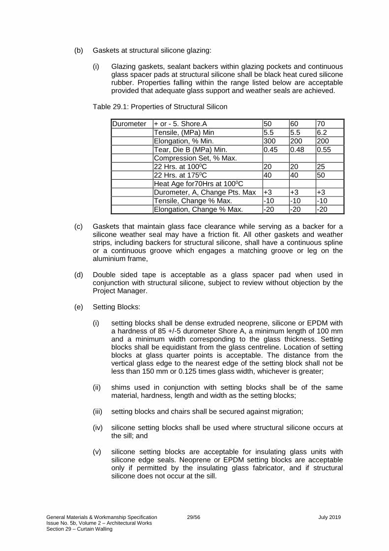
General Materials & Workmanship Specification 29/56 July 2019 Issue No. 5b, Volume 2 – Architectural Works Section 29 – Curtain Walling
(b) Gaskets at structural silicone glazing:
(i) Glazing gaskets, sealant backers within glazing pockets and continuous glass spacer pads at structural silicone shall be black heat cured silicone rubber. Properties falling within the range listed below are acceptable provided that adequate glass support and weather seals are achieved.
Table 29.1: Properties of Structural Silicon
Durometer + or - 5. Shore.A 50 60 70
Tensile, (MPa) Min 5.5 5.5 6.2
Elongation, % Min. 300 200 200
Tear, Die B (MPa) Min. 0.45 0.48 0.55
Compression Set, % Max.
22 Hrs. at 1000C 20 20 25
22 Hrs. at 1750C 40 40 50
Heat Age for70Hrs at 1000C
Durometer, A, Change Pts. Max +3 +3 +3
Tensile, Change % Max. -10 -10 -10
Elongation, Change % Max. -20 -20 -20
(c) Gaskets that maintain glass face clearance while serving as a backer for a
silicone weather seal may have a friction fit. All other gaskets and weather strips, including backers for structural silicone, shall have a continuous spline or a continuous groove which engages a matching groove or leg on the aluminium frame,
(d) Double sided tape is acceptable as a glass spacer pad when used in
conjunction with structural silicone, subject to review without objection by the Project Manager.
(e) Setting Blocks:
(i) setting blocks shall be dense extruded neoprene, silicone or EPDM with
a hardness of 85 +/-5 durometer Shore A, a minimum length of 100 mm and a minimum width corresponding to the glass thickness. Setting blocks shall be equidistant from the glass centreline. Location of setting blocks at glass quarter points is acceptable. The distance from the vertical glass edge to the nearest edge of the setting block shall not be less than 150 mm or 0.125 times glass width, whichever is greater;
(ii) shims used in conjunction with setting blocks shall be of the same
material, hardness, length and width as the setting blocks;
(iii) setting blocks and chairs shall be secured against migration;
(iv) silicone setting blocks shall be used where structural silicone occurs at the sill; and
(v) silicone setting blocks are acceptable for insulating glass units with
silicone edge seals. Neoprene or EPDM setting blocks are acceptable only if permitted by the insulating glass fabricator, and if structural silicone does not occur at the sill.

General Materials & Workmanship Specification 30/56 July 2019 Issue No. 5b, Volume 2 – Architectural Works Section 29 – Curtain Walling
(f) Side/Centring Blocks:
(i) side blocks shall be provided at both jambs, between the mid-height and top corner of the glass. Blocks shall be 55 +/- 5 durometer. Shore A dense neoprene, silicone or EPDM. Install block with clearance between block and bearing- surface. Blocks shall be positively secured in position;
(ii) side blocks are not required where glass is supported along the vertical
edges with structural silicone; and
(iii) extruded silicone side blocks are acceptable for insulating glass units with silicone edge seals. Neoprene or EPDM side blocks are acceptable only if permitted by the insulating glass fabricator.
(g) Structural Gaskets:
(i) structural gaskets shall be composed of rubber-based material having
proven compatibility with silicone sealants when used in a 'wet' system;
(ii) 'Dry' system gaskets shall be extruded with integral locking strips or ‘zipper' type insertions producing a compression grip on the frame structure and the glass. Gaskets shall be continuously placed around the glazing. The dimensional tolerance and the resulting edge bite shall be as recommended by the manufacturer; and
(iii) colour of the gaskets shall be reviewed without objection by the Project
Manager. 29.5.8 Anchors in Concrete and Masonry
(a) Anchors embedded in concrete and masonry shall be hot-dip galvanized rolled steel, or hot-dip galvanized cold-formed steel in compliance with BS 729. Galvanize steel parts of anchors. After field welding, the Contractor shall remove weld slag and touch up galvanized surface.
(b) Strength of embedded anchors shall be developed by integral projections or by welded deformed bars or headed studs.
(c) Through bolts are acceptable at masonry, provided that bearing plates are
used at both masonry surfaces. Expansion bolts shall only used with the permission of the Project Manager.
(d) All bolts shall be cast-in-situ at concrete. Expansion bolts shall only used with
the permission of the Project Manager.
(e) Self drilling, self threading screws are not acceptable. Screws in plugs and powder-actuated fasteners shall not be used.

General Materials & Workmanship Specification 31/56 July 2019 Issue No. 5b, Volume 2 – Architectural Works Section 29 – Curtain Walling
29.5.9 Fasteners
(a) Fastener requirements listed below shall be applicable to screws, bolts, nuts, washers, rivets and pins.
(b) Fasteners outboard of or within a glazing pocket, gutter, and flashed cavity or
other potentially wet location (after completion of construction) shall be stainless steel type 302 or 304. Fasteners inboard of potentially wet locations shall be stainless steel type 302 or 304, cadmium plated carbon steel or zinc plated carbon steel.
(c) Stainless steel fasteners shall comply with BS 3111: Part 2 and BS 6105.
Stainless steel washers shall comply with BS 4320 and BS 4464 as far as sizes and tolerances are concerned.
(d) Bolts, screws, nuts and washers shall comply with section 22 (Steelwork).
(e) The Contractor shall provide lock washer or other locking device at all bolted
connections.
(f) Powder actuated fasteners shall not be used.
(g) Aluminium fasteners shall comply with BS 1473.
(h) Actions subsequent to any failure of material or test specimens shall be in accordance with the requirements of section 22 (Steelwork).
29.5.10 Shims
(a) At connections subject to thermal movement or other movement, the Contractor shall separate all pairs of moving surfaces with friction reducing pads. Pads shall have minimum 3 mm thickness, sufficiently reduce fiction to wear, and be positively retained in position (open ended slots are not acceptable). Pads shall not be subjected to heat damage from welding or cutting, or to excessive pressure from over-tightening of bolts.
(b) Shims which transfer shear forces (tending to slide one shim against another) shall be steel plates, set in a staggered pattern and fillet welded, to each other and to the adjacent steel surfaces. The shims and welds shall be structurally designed to support the applied loads.
(c) Plastic shims are acceptable at static connections for which the shims transfer
only compressive forces.
(d) Wood shims shall not be used.
29.5.11 Weep Hole Filters
Weep hole filters shall be 8 to 18 pore per centimetre PVC coated open cell urethane foam, compressed 30 to 50 percent.
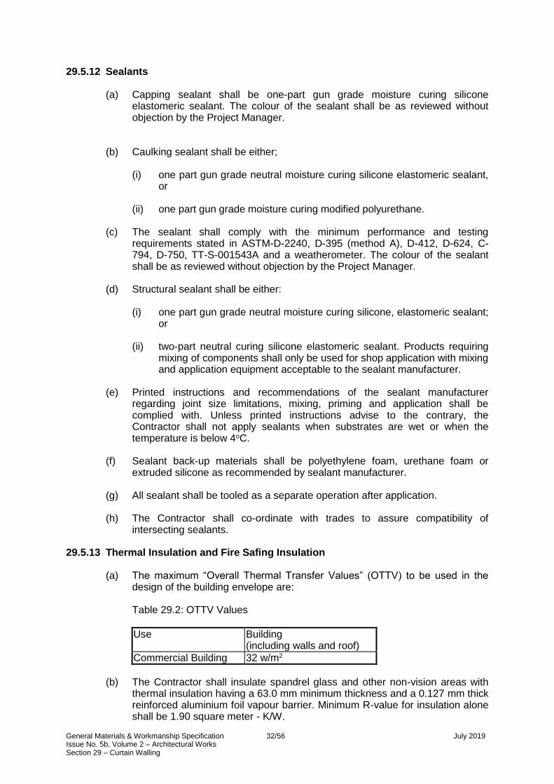
General Materials & Workmanship Specification 32/56 July 2019 Issue No. 5b, Volume 2 – Architectural Works Section 29 – Curtain Walling
29.5.12 Sealants
(a) Capping sealant shall be one-part gun grade moisture curing silicone elastomeric sealant. The colour of the sealant shall be as reviewed without objection by the Project Manager.
(b) Caulking sealant shall be either;
(i) one part gun grade neutral moisture curing silicone elastomeric sealant, or
(ii) one part gun grade moisture curing modified polyurethane.
(c) The sealant shall comply with the minimum performance and testing
requirements stated in ASTM-D-2240, D-395 (method A), D-412, D-624, C-794, D-750, TT-S-001543A and a weatherometer. The colour of the sealant shall be as reviewed without objection by the Project Manager.
(d) Structural sealant shall be either:
(i) one part gun grade neutral moisture curing silicone, elastomeric sealant;
or
(ii) two-part neutral curing silicone elastomeric sealant. Products requiring mixing of components shall only be used for shop application with mixing and application equipment acceptable to the sealant manufacturer.
(e) Printed instructions and recommendations of the sealant manufacturer
regarding joint size limitations, mixing, priming and application shall be complied with. Unless printed instructions advise to the contrary, the Contractor shall not apply sealants when substrates are wet or when the temperature is below 4oC.
(f) Sealant back-up materials shall be polyethylene foam, urethane foam or
extruded silicone as recommended by sealant manufacturer.
(g) All sealant shall be tooled as a separate operation after application.
(h) The Contractor shall co-ordinate with trades to assure compatibility of intersecting sealants.
29.5.13 Thermal Insulation and Fire Safing Insulation
(a) The maximum “Overall Thermal Transfer Values” (OTTV) to be used in the design of the building envelope are:
Table 29.2: OTTV Values
Use Building (including walls and roof)
Commercial Building 32 w/m2
(b) The Contractor shall insulate spandrel glass and other non-vision areas with
thermal insulation having a 63.0 mm minimum thickness and a 0.127 mm thick reinforced aluminium foil vapour barrier. Minimum R-value for insulation alone shall be 1.90 square meter - K/W.

General Materials & Workmanship Specification 33/56 July 2019 Issue No. 5b, Volume 2 – Architectural Works Section 29 – Curtain Walling
(c) Insulation shall be retained by aluminium or galvanized steel clips or straps, or integral pockets within the window frames. Maximum spacing of clips and straps shall be 600 mm. Welded or glued impaling pins shall not be permitted. Maintain 25 mm nominal air space between insulation and glass.
(d) The Contractor shall support insulation where it contacts fire-safing to prevent
bow of insulation from pressure exerted by fire-safing.
(e) The Contractor shall completely fill void at floor and roof edges with fireproof material with thickness as required to provide a 2-hour fire rating.
(f) The Contractor shall support fire-safing insulation on galvanized steel support
clips spaced at a maximum of 450 mm centres. 29.5.14 Operable Windows
Except as otherwise specified herein, operating windows shall also comply with (as a minimum) BS 4873 and BS 6375:
(a) Weather-strips, glazing gaskets and glazing blocks shall be extruded
neoprene. The Contractor shall provide gaskets on both sides of the vent glass.
(b) The required test specimen size shall be the maximum size operable window
for the Works.
(c) Locks and strikes shall be white bronze or type 302 or 304 stainless steel. The Contractor shall provide a minimum of two locks and two strikes per vent.
(d) Fixed frames and vent frames shall be extruded aluminium. Vent frames shall
consist of a tubular profile.
(e) Weather-strips shall have a continuous splice engaged in a continuous groove in the aluminium sash and/or fixed frame. Two continuous lines of weather-strip are required at vent perimeters.
(f) Balance arms shall be four-bar stainless steel type 302 or 304 with adjustable
friction shoe. Provide two balance arms per vent.
(g) The Contractor shall provide two limit stops per operable window. Material shall be type 302 or 304 stainless steel. Stops shall restrict clear opening to 100 mm. Effective ventilating area shall be based on the maximum clear opening, not on the gross window area.
(h) Special keys shall be required to open the operable windows.
(i) Hinges and fastening mechanisms shall withstand positive and negative
pressures due to specified wind conditions when the windows are in the open or closed positions.

General Materials & Workmanship Specification 34/56 July 2019 Issue No. 5b, Volume 2 – Architectural Works Section 29 – Curtain Walling
29.5.15 Aluminium Honeycomb Panels
(a) Overall nominal thickness shall be 25.0 mm.
(b) Face and back sheets shall be aluminium with nominal thickness of 1.0 mm. Alloy shall be of the 3xxx, 5xxx or 6xxx series and shall satisfy structural and finish requirements. Formed edge returns and seal edges shall be provided with silicone sealant. Bonding surfaces shall be chemically pre-treated to assure effective and durable bond.
(c) Core shall be hexagonal cell aluminium foil with minimum nominal thickness of
0.0762 mm. Cell size shall not exceed 6.0 mm measured across flats. Foil shall have an organic corrosion resistant coating. Alloy shall be 3003, 5052, or 2024.
(d) Adhesive shall be a thermal setting modified epoxy with a minimum set
temperature of 121oC. The adhesive shall form a fillet at the perimeter of each cell, and shall continuously bond each cell to the face and back sheets.
(e) The face, sheet back sheet, and core of each panel shall be cut from single
piece of material.
(f) For panels in place, deviation from flatness of exterior face shall not exceed 3.0 mm along any straight line which extends from a panel edge to any other edge. Where the edge is concealed, the nearest exposed point to the edge shall be used.
(g) Panel exterior face shall be free of visual discontinuities such as ripples,
creases, dents, bubbles and blisters, regardless of the measured deviation from flatness at such discontinuities.

General Materials & Workmanship Specification 35/56 July 2019 Issue No. 5b, Volume 2 – Architectural Works Section 29 – Curtain Walling
29.5.16 Louvres
(a) Louvres shall consist of extruded aluminium perimeter frames and blades.
(b) Frame corners and blade ends shall be welded or fastened with 300 series stainless steel screws.
(c) Blades shall be provided with concealed extruded aluminium stiffeners, such
that vector sum of blade deflections parallel to blade principal axes does not exceed 1/175 times span at design pressure. Assume that pressure acts perpendicular to the plane formed by the corners of the perimeter frame, and that the tributary area for one blade equals its projected area on the same plane.
(d) Where required, the free area of louvres shall comply with mechanical
requirements.
(e) Inactive louvres shall be closed by aluminium sheet with minimum 3.0 mm nominal thickness, fastened and sealed to the indoor louvre surfaces.
(f) The Contractor shall provide aluminium bird screen mesh at active louvres.
Mesh wire shall have 1.6 mm minimum nominal thickness. Openings within mesh shall be 13.0 mm.
(g) Finish for louvres and screens shall be the same as for other aluminium
members. 29.5.17 Copings
Copings shall comply with the following: (a) Copings shall comprise aluminium minimum 3.0 mm thick or stainless steel
minimum 2.0 mm thick as shown on the Employer’s Drawings. The surface of aluminium shall have finish to match colour of framing.
(b) Copings shall be rigid, reinforced with a metal frame if required and shall be
fixed rigidly to the structure. Copings shall be strong enough to resist forces due to typhoon and casual impact.
(c) Ends of coping panels and joints to curtain wall frame shall be tightly sealed
up and an effective drainage system shall be provided to drain out any water that may penetrate through the joints.

General Materials & Workmanship Specification 36/56 July 2019 Issue No. 5b, Volume 2 – Architectural Works Section 29 – Curtain Walling
29.5.18 Concealed and Exposed Flashings
(a) Acceptable materials for flashings are PVC sheet, neoprene sheet, stainless steel sheet and mill finish aluminium sheet. Minimum thicknesses are 1.6 mm for PVC and neoprene, 0.25 mm for stainless steel, and 1.0 mm for aluminium. Aluminium shall have a bituminous coating against dissimilar materials.
(b) Sealed lap joints, end dams and transitions shall be provided to gutters,
dressings to roofs/abutments, louvres and screens to A/C intakes and exhausts.
(c) PVC sheet and neoprene sheet shall not be used as primary gutters, which
shall be metal with suitable corrosion protection.
(d) Exposed flashing shall be strong enough to resist forces due to typhoon and casual impact.
29.5.19 Finishes Generally
(a) Exposed metal surfaces shall be finished to match the appearance, colour and
texture of the samples as reviewed without objection by the Project Manager.
(b) Finishes to metals shall comply with the following:
(i) clear or coloured anodic finish to aluminium in compliance with BS 3987;
(ii) no. 8 bright polished finish to exposed faces of stainless steel;
(iii) no. 7 polished finish to stainless steel or chromium-plated ironmongery; and
(iv) organic coatings in compliance with BS 4842 and/or BS 6496.
29.5.20 Protective Treatments
(a) Protective treatment to concealed steel parts of the curtain wall system such as fixings, connectors, etc., shall be hot-dip galvanizing in compliance with BS 729.
(b) All welding and provision of holes shall be completed before galvanizing.
(c) No in-situ welding is allowed unless previously reviewed without objection by
the Project Manager. 29.5.21 Anodic Coating to Aluminium
The thickness of anodic coating shall be minimum 0.025 mm. Coloured anodic coatings and testing shall be as reviewed without objection by the Project Manager.

General Materials & Workmanship Specification 37/56 July 2019 Issue No. 5b, Volume 2 – Architectural Works Section 29 – Curtain Walling
29.5.22 Organic Coating Finish to Aluminium
(a) Organic coating finish shall comply with the following requirements:
(i) all coatings, when cured, shall be visibly free of flowlines, streaks, sags, blisters or other surface imperfections;
(ii) all finishes shall match in gloss, and fall within the colour range of the
samples previously reviewed without objection by the Project Manager; and
(iii) dry film thickness of coating on exposed surface, when measured in
accordance with BS 4842 shall not be less than 45 microns, except in channel recesses and internal corners, which shall be visually covered.
(b) The Contractor shall paint all surfaces of metal cladding.
(c) The Contractor shall prepare and submit colour samples to the Project
Manager for review without objection. After selection by the Project Manager, the Contractor shall prepare 6 sets each of two samples which shall define the colour and gloss range and submit to the Project Manager for review without objection. Samples shall be identified and attached with a full laboratory report in compliance with BS 4842 and BS 6496.
(d) Painted aluminium finish shall be factory oven cured with a minimum two-coat
finish of fluoropolymer resin supplied by a licensed formulator. The licensed formulator shall identify the finish which he supplies to meet the minimal requirements for formulation as set forth in the licensing agreement
(e) Application of the finish shall be carried out in accordance with the
specifications issued by the licensed formulator and by an applicator specifically approved by one (or more) of the formulators. The applicator shall provide written notification of approval by a formulator prior to application of the finish. The formulation shall contain at least 70% fluoropolymer resin in the residual solids.
(f) The Contractor shall pre-treat metal surfaces in accordance with the
procedure recommended by the manufacturer to provide proper surfaces for coating.
(g) Pigmented organic coatings for extrusions, structural shapes, sheet or plate,
spray applied in the factory, shall comply with BS 4842 and BS 6496.
(h) Field touch-up of painted aluminium shall only be permitted with the written permission of the Project Manager. Unless touch-up is authorized, the Contractor shall replace damaged material with new material.

General Materials & Workmanship Specification 38/56 July 2019 Issue No. 5b, Volume 2 – Architectural Works Section 29 – Curtain Walling
29.5.23 Aluminium Finish at Structural Silicone
(a) Mill finish shall not be permitted at structural silicone bonding surfaces.
(b) Aluminium surface to which structural silicone will be adhered shall have a finish which demonstrates by test the ability to satisfy specified requirements. Subject to testing, acceptable finishes shall be as follows:
(i) factory applied two-coat oven cured fluoropolymer paint conforming to
BS 4842 and/or BS 6491;
(ii) architectural Class 1 anodising conforming to BS 3987;and
(iii) alodine conversion coating.
29.6 SUBMISSIONS
29.6.1 Particulars of the Curtain Walling System
The following particulars of the proposed curtain walling system shall be submitted to the Project Manager for review without objection. Contractor’s Drawings shall be certified by a chartered structural engineer, showing materials in place. Contractor’s Drawings shall include elevations, floor plans, sections and full size details. Drawings shall include the following information:
(a) assembly and waterproofing of curtain wall;
(b) glass and metal thickness;
(c) metal alloy, temper and finish;
(d) glass strength, tint, coating, opacifier, frit and safety backing;
(e) fastener alloy, strength, plating, diameter, length and spacing;
(f) glazing materials identification;
(g) sealants identification by product name;
(h) relative layout of walls, beams, column and slabs with dimensions noted;
(i) dimensioned position of glass edge relative to metal surface;
(j) provisions for thermal movements and building movements;
(k) locations of, and details for, any embedded anchors;
(l) identification of, and details for, thermal insulation;
(m) weld information and weld symbols conforming to BS 499;
(n) glazing details applicable to replacement glass, with outline of procedure for
glass replacement;
(o) provisions for adjustment of anchors relative to tolerances of building structure;

General Materials & Workmanship Specification 39/56 July 2019 Issue No. 5b, Volume 2 – Architectural Works Section 29 – Curtain Walling
(p) details of spandrels, copings, louvers and operable window;
(q) details of ceiling and bottom/floor closure panels or strips if applicable;
(r) details of fire barriers between perimeters of floors and curtain wall; and
(s) details of lightning protection. 29.6.2 Structural Calculations
The Contractor shall submit Contractor’s Drawings including fully co-ordinated structural calculations, certified by a chartered structural engineer. Calculations shall be legible and shall incorporate sufficient cross-references to the detailed drawings submitted as part of the same design package, to make the calculations readily understandable. Test reports shall not substitute calculations. Calculations shall include the following information:
(a) analysis for applicable loads on framing members;
(b) analysis for all applicable loads on anchors, including anchors embedded in
concrete;
(c) section property computations for framing members;
(d) analysis of stress in structural silicone applications at vision or spandrel glass lights; and
(e) certification of a chartered structural engineer.
29.6.3 Prototypes
Drawings and structural calculations shall be submitted for prototypes. The requirements for prototypes shall be the same for the actual Works, with particular reference to conditions under which the prototypes will be tested.
29.6.4 Additional Submittal Requirements
The Contractor shall: (a) prior to or at the same time as the first submittal of structural calculations for
review by the Project Manager, provide dimensioned die drawings for all aluminium extrusions. In the event that extrusion profiles are not finalized, provide die drawings for the profiles contemplated at that time. If profiles are revised, provide revised die drawings with the first calculation or shop drawing submittal, which follows the revision. Die drawings shall show all profile dimension, metal thickness, alloy and temper;
(b) prior to manufacture, provide die drawings of gaskets and weather-strips. Die
drawings shall show all profile dimensions and shall identify materials;
(c) prior to manufacture, provide glass manufacturer's wind pressure analysis and thermal stress analysis, as well as glass manufacturer's review of Contractor’s Drawings stating that details are suitable for the proposed glass products.
(d) prior to manufacture, provide sealant manufacturer's test reports confirming
sealant adhesion compatibility and absence of staining for all relevant substrates.

General Materials & Workmanship Specification 40/56 July 2019 Issue No. 5b, Volume 2 – Architectural Works Section 29 – Curtain Walling
(e) prior to manufacture, provide certification that insulating glass –conforms to BS 5713.
(f) prior to submitting any documents for review, submit laboratory test reports for
structural silicone assembly, as required under section 29.8;
(g) submit samples; refer to section 29.6.5; and
(h) submit structural adequacy tests of anchorages; refer to section 29.8. 29.6.5 Samples
(a) The following samples of proposed materials together with fully glazed samples of principal junctions and assemblies shall be submitted to the Project Manager for review without objection.
(b) Submission shall consist of three samples of each material and principal
junction or assembly, two to be retained by the Project Manager and the other to be returned after review without objection by the Project Manager which shall be marked by the Project Manager. Samples of materials required shall be as follows;
Table 29.3: Curtain Wall Material Samples
Aluminium/Stainless steel sections 300 mm length of each.
Galvanized mild steel 300 mm length of each section.
Sheet, plate, mesh 300 x 300 mm piece of each type.
Glass 600 x 600 mm piece per type and/or edge finish.
Fastening devices each type.
Sealants 150 mm cured sample each type.
Gaskets 300 mm length of each type.
Flashings 300 x 300 mm piece of each type.
Stone 300 x 300 mm piece of each type.
(c) Samples shall show the complete range of colour, texture and other
characteristic changes through the manufacture, fabrication, assembly, installation and cleaning processes. The Contractor shall submit finished samples of every extrusion or section to be used and of every other material of the thickness and weight as required by the Project Manager. Aluminium samples shall include samples of high and low colour range of anodic and organic coating finish and shall be labelled accordingly.

General Materials & Workmanship Specification 41/56 July 2019 Issue No. 5b, Volume 2 – Architectural Works Section 29 – Curtain Walling
29.7 WORKMANSHIP
29.7.1 Workmanship generally
(a) Material, components and systems shall be used in compliance with the standards and procedures of the appropriate manufacturers. All work shall satisfy the requirements of the Specification. Practice shall conform to the relevant part and in the priority of:
(i) CP-8118 Part 1 & 2- Structural Use of Aluminium;
(ii) BS 6262 - Code of Practice for Glazing of Buildings;
(iii) BS 8200 - Design of Non-Load Bearing External Vertical Enclosures of
Buildings;
(iv) BS 5889 - Specification for One-Part Gun Grade Silicone Based Sealants;
(v) Recommended Glazing Guidelines for Reflective Insulating Glass by
AAMA;
(vi) Aluminium Curtain Wall Design Guide Manual by AAMA;
(vii) Metal Curtain Wall Manual by AAMA.
(b) No temporary stress or force shall be applied at any time to the assembly, units, individual components or fixing devices which have not been designed to withstand. Temporary supplementary frame stiffeners for curtain wall units shall be provided for handling purposes when required.
(c) The Contractor shall conform strictly to the material finishes, shapes, sizes,
thickness, and joint locations required by the agreed shop drawings and the Specification.
(d) The Contractor shall match all materials to produce continuity of line, colour
and texture.
(e) The Contractor shall store glass on the Site in a dry well-ventilated sheltered location.
(f) Handling glass shall be kept to a minimum.
(g) The Contractor shall carry out all final fitting and assembly work on the Site in
a workshop established and equipped for that purpose.
(h) All components exposed in the finished work shall be free from warping, oil-canning effects and the telegraphing of welds, studs and other fasteners.
(i) The Contractor shall provide specified finishes on all exposed surfaces and
provide specified galvanizing on concealed steel.
(j) Systems with glass supported at all edges by structural silicone shall be unitised and shall be fully assembled, including silicone and glass, in the shop.
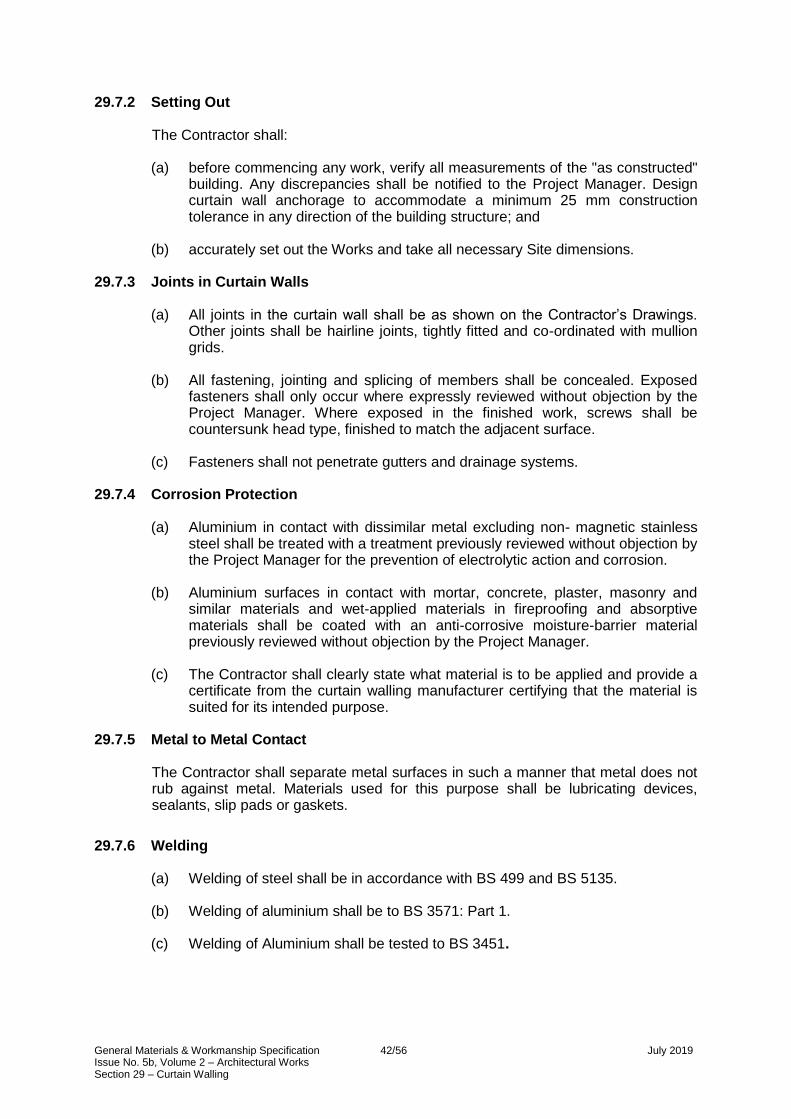
General Materials & Workmanship Specification 42/56 July 2019 Issue No. 5b, Volume 2 – Architectural Works Section 29 – Curtain Walling
29.7.2 Setting Out The Contractor shall: (a) before commencing any work, verify all measurements of the "as constructed"
building. Any discrepancies shall be notified to the Project Manager. Design curtain wall anchorage to accommodate a minimum 25 mm construction tolerance in any direction of the building structure; and
(b) accurately set out the Works and take all necessary Site dimensions.
29.7.3 Joints in Curtain Walls
(a) All joints in the curtain wall shall be as shown on the Contractor’s Drawings. Other joints shall be hairline joints, tightly fitted and co-ordinated with mullion grids.
(b) All fastening, jointing and splicing of members shall be concealed. Exposed
fasteners shall only occur where expressly reviewed without objection by the Project Manager. Where exposed in the finished work, screws shall be countersunk head type, finished to match the adjacent surface.
(c) Fasteners shall not penetrate gutters and drainage systems.
29.7.4 Corrosion Protection
(a) Aluminium in contact with dissimilar metal excluding non- magnetic stainless steel shall be treated with a treatment previously reviewed without objection by the Project Manager for the prevention of electrolytic action and corrosion.
(b) Aluminium surfaces in contact with mortar, concrete, plaster, masonry and
similar materials and wet-applied materials in fireproofing and absorptive materials shall be coated with an anti-corrosive moisture-barrier material previously reviewed without objection by the Project Manager.
(c) The Contractor shall clearly state what material is to be applied and provide a
certificate from the curtain walling manufacturer certifying that the material is suited for its intended purpose.
29.7.5 Metal to Metal Contact
The Contractor shall separate metal surfaces in such a manner that metal does not rub against metal. Materials used for this purpose shall be lubricating devices, sealants, slip pads or gaskets.
29.7.6 Welding
(a) Welding of steel shall be in accordance with BS 499 and BS 5135.
(b) Welding of aluminium shall be to BS 3571: Part 1.
(c) Welding of Aluminium shall be tested to BS 3451.

General Materials & Workmanship Specification 43/56 July 2019 Issue No. 5b, Volume 2 – Architectural Works Section 29 – Curtain Walling
(d) The type, size and spacing of welds shall be as shown on the Contractor’s Drawings previously reviewed without objection by the Project Manager. Welding materials and methods shall not cause distortion, discolouration, or result in any other adverse effect on the required profiles and finishes of the exposed curtain wall.
(e) Weld spatter and welding oxides on exposed surfaces shall be removed and
prime painted with zinc rich coating.
(f) Unless otherwise shown or specified, weld beads on exposed surfaces shall be ground and finished to match and blend with finish on adjacent metal. Grinding and polishing of nonferrous metal shall be done only with clean wheels and compounds free from iron and iron compounds. No soldering and/or brazing shall be allowed.
29.7.7 Application of Sealants and Gaskets
(a) Sealant application shall be in compliance with BS 5889. Sealant and gaskets shall be as shown on the Contractor’s Drawings previously reviewed without objection by the Project Manager.
(b) The design of all sealed joints shall be in accordance with the
recommendation of the sealant and/or gasket manufacturer.
(c) The Contractor shall protect all adjoining surfaces to sealants and gaskets against staining.
(d) Joints, joint surfaces and glazing rebates shall be clean, dry, and free of any
material that may have an adverse effect on the bonding or sealing of the sealant and gasket materials or on the proper drainage of the glazing rebates.
(e) The Contractor shall apply sealants and gaskets under the conditions and in the manner recommended by the manufacturer. No sealant that has started to set in its container or has exceeded its shelf life shall be used. No sealant shall be applied externally during raining period.
(f) The sealant manufacturer shall provide written notification if the relevant
substrates in contact with sealants will or will not require priming. The recommendations shall be based on tests conducted by the sealant manufacturer using samples of the relevant substrates for the project. Unless printed instructions state to the contrary sealant shall not be applied when substrates are wet or when the temperature is below 4.5 oC.
(g) The Contractor shall fill all joints continuously and completely with sealant,
forming a neat, uniform, concave or flat bead finish flush with adjoining surfaces unless otherwise shown on the drawings. All sealant surfaces shall be tooled smooth.
(h) Exposed sealants shall be installed so that top surfaces of the horizontal
sealant beads are sloped to drain water away.
(i) Glazing gaskets shall be of the profile, dimension and durometer hardness required to support the glass and resist water penetrations. Exterior glazing gaskets shall have factory made pre-moulded corners.

General Materials & Workmanship Specification 44/56 July 2019 Issue No. 5b, Volume 2 – Architectural Works Section 29 – Curtain Walling
29.7.8 Render Stops
Incorrect placement, levelling or lining-through of angles to in-situ finishing and the like fixed by others shall be immediately reported in writing to the Project Manager.
29.7.9 Sequence of Installation
The Contractor shall co-ordinate and carry out the installation of the curtain wall in sequence with related work operations to be executed by others to achieve a weather-tight and satisfactory visual relationship between the various components and the structure, finishes and weather seals.
29.7.10 Erection
(a) The Contractor shall install materials in accordance with Contractor’s Drawings previously reviewed without objection by the Project Manager; align and anchor materials to building structure; and seal joints within the Works of this section and at joints with adjacent construction.
(b) Tolerances:
(i) The Contractor shall provide anchor adjustment capability for the full range of specified tolerances for the building structure and to accommodate, construction tolerances and short term building movements (i.e. concrete column settlement).
(ii) Deviation from plumb, level or dimensioned angle shall not exceed 3.0
mm per 3,600 mm of length of any member, 6.0 mm in any total run in any line.
(iii) Deviation from theoretical position in plan or elevation, including
deviation from plumb, level or dimensioned angle, shall not exceed 10.0 mm total at any location. Change in deviation shall not exceed 3.0 mm per 3,600 mm run in any direction.
(iv) Maximum offset from alignment between two consecutive members
placed end to end shall not exceed 1.5 mm.
(v) Maximum offset between glass framing members at corners of glazing pocket shall not exceed 0.8 mm.
(c) Anchorage:
(i) The Contractor shall anchor component parts securely in place by
bolting. Welding may be used if prior review without objection by the Project Manager. Slip pads shall be installed between moving parts.
(ii) The Contractor shall provide non-corrosive separators between
dissimilar materials.
(iii) The Contractor shall remove weld slag and apply prime paint over welds. Hot-dip galvanizing that is damaged by welding or other causes shall be touched up.

General Materials & Workmanship Specification 45/56 July 2019 Issue No. 5b, Volume 2 – Architectural Works Section 29 – Curtain Walling
(iv) Where slots or oversize holes are provided for adjustment only, the Contractor shall secure the connection after final adjustment. Interlocking serrations in extruded aluminium brackets and washers are acceptable. Steel weld washers with 6.0 mm minimum thickness are acceptable with steel brackets. Special washers or nuts which rely on friction and/or surface indentation of the fastened part shall not be permitted.
(v) Bolts shall be double nutted, have an acceptable spring washer or be
painted/coated with a lock-tight liquid to prevent bolts from loosening.
(vi) All fixings shall be concealed when the work is completed.
(d) The Contractor shall clean surfaces to be sealed, and install backers, bond breakers, primers and sealants in accordance with Contractor’s Drawings, test results and manufacturer recommendations. The Contractor shall tool sealants as a separate operation after application and immediately remove any masking.
(e) The Contractor shall install thermal insulation, vapour barrier and fire-safing
insulation with specified supports.
(f) Adjustment:
(i) The Contractor shall adjust operating windows and doors for proper fit within fixed frame.
(ii) The Contractor shall adjust weather-strips for continuous contact and
seal in closed position.
(iii) The Contractor shall adjust hardware for proper operation from closed and locked position to fully open position.
29.7.11 Glazing
(a) Glazing shall comply with BS 6262 and in accordance with the manufacturer's recommendations. Glass and glazing materials shall be compatible with each other and the glass shall be protected from damage and staining of any kind.
(b) The weather seal at glass perimeters shall be a combination of sponge and
dense gaskets. Gaskets shall be hot melt injection moulded at corners where compatible with installation procedure. Where gasket joints occur, the Contractor shall tightly butt ends and seal with a compatible sealant. Gasket joints shall not occur at locations other than corners.
(c) Glass shall be new. Glass shall be of the specified type and quality with cleanly cut edges and sharp corners. Inspect glass before installation. Defective glass shall not be installed.
(d) Before setting glass, the Contractor shall inspect frame for proper dimensions
and squareness. Frame and/or glass size shall be adjusted as required to meet specified requirements for glass bite dimensions and glass edge clearance.

General Materials & Workmanship Specification 46/56 July 2019 Issue No. 5b, Volume 2 – Architectural Works Section 29 – Curtain Walling
(e) Except otherwise specified, glass bite shall comply with BS 6262. The Contractor shall provide a minimum nominal glass bite of 13 mm. Where joint movement will result in variable glass bite, nominal bite shall be increased to provide 10.0 mm minimum bite and 6.0mm minimum edge clearance. In no case shall the front and back clearances be less than 5.0 mm.
(f) The Contractor shall thoroughly clean glazing pocket before setting glass.
Solvents shall be compatible with finished aluminium, glass and glazing materials. Setting blocks shall be equidistant from the glass centreline. Location of setting blocks at glass quarter points is acceptable. The distance from the vertical glass edge to the nearest edge of the setting block shall not be less than 150 mm, or 0.125 times glass width, whichever is greater. Side blocks shall be located between the mid-height and top corner of the glass. Side blocks, setting blocks and chairs shall be positively retained in position.
(g) Fasteners shall not penetrate glazing pockets.
(h) The Contractor shall remove and replace stops and apply sealants as required
to complete glass installation.
(i) The Contractor shall defer glazing of openings which are obstructed during construction. Glazing of such opening shall be carried out when obstructions are removed.
(j) The Contractor shall leave glass in crates until just prior to installation. Any
glass which breaks or sustains edge damage, surface damage or damage to reflective coating shall be replaced.
(k) The Contractor shall clean, prime and mask at structural silicone joints within 8
hours before applying the silicone.
(l) The Contractor shall temporarily clamp glass during cure of structural silicone. After sufficient cure, the Contractor shall remove clamps and fill any gaps in silicone.
(m) The Contractor shall mask glass and aluminium during application of structural
silicone, and remove masking immediately after tooling sealant.
(n) Structural silicone shall not be applied to edges of insulating glass units, or to edges of laminated glass units. Sealants used as weather seals shall not be adhered to, or placed against, the edge of a laminated glass unit inter-layer

General Materials & Workmanship Specification 47/56 July 2019 Issue No. 5b, Volume 2 – Architectural Works Section 29 – Curtain Walling
29.7.12 Stone Fabrication
(a) Fabrication tolerances for exposed surface of individual pieces of stone shall be as follows:
(i) length and height (or width): 1.0 mm;
(ii) depth of a saw cut: 2.0 mm;
(iii) depth of a drilled hole: 3.0 mm;
(iv) deviation from flat plane in 1200 mm, any direction: 2.0 mm;
(v) deviation from square: 2.0 mm difference in diagonals;
(vi) deviation from nominal thickness: 2.0 mm; and
(vii) position of kerfs cut relative to outdoor face: ± 1.0 mm.
(b) Fabrication tolerances for exposed surface of one stone system assembly with
stone anchored to a support system shall be as follows:
(i) sealant joint width between pieces of stone +/- 25% of nominal (Joints which absorb thermal and building movements shall require stricter tolerance.);
(ii) overall length and height (or width), stone edge to stone edge: 3.0 mm;
(iii) offset (in/out) between adjacent stone edges 1.5 mm maximum;
(iv) deviation from flat plane for overall length 5.0 mm;
(v) deviation from flat plane for overall height (or width): 3.0 mm;
(vi) difference in overall diagonals measured to outside corners of stone: 5.0
mm maximum;
(vii) deviation from straight line along entire length of vertical edge: 2.5 mm maximum;
(viii) deviation from straight line along entire length of horizontal edge: 2.5
mm maximum;
(ix) offset (in plane) between adjacent granite corners: 3.0 mm maximum (distance between parallel horizontal or vertical lines through corners);
(x) window opening dimension: 6.0 mm; and
(xi) where more than one tolerance applies, the stricter tolerance shall
govern.

General Materials & Workmanship Specification 48/56 July 2019 Issue No. 5b, Volume 2 – Architectural Works Section 29 – Curtain Walling
29.7.13 Repairs to Anodic Coating
(a) Repairs of damage to finished surfaces by mechanical means (other than those specified) or by painting are strictly forbidden unless reviewed without objection by the Project Manager.
(b) Surfaces to be finished shall be free from mechanical imperfections such as
scratches, scrapes and dents. Finished surfaces shall be free from finished imperfections such as spots, stains and streaks.
(c) Materials may be finished more than once provided that all specified
requirements are satisfied. 29.7.14 Protection and Cleaning
The Contractor shall: (a) provide protective sheeting or tape to aluminium or stainless steel members
and ancillaries;
(b) pack and store materials to prevent surface damage or contamination, distortion breakage or structural weakening;
(c) remove sheeting or tape as soon as practical so as not to stain and/or leave
an adhesive residue on the relevant substrates;
(d) protect glass against damage, discolouration or staining and replace damaged or broken glass, regardless of the cause.
29.7.15 Labels
No labels shall be adhered to glass other than those of the glass manufacturer which shall be adhered with a non-alkaline adhesive. The Contractor shall remove all labels from glass after glazing.
29.7.16 Cleaning
(a) The Contractor shall thoroughly wash and clean the work immediately prior to requesting a Completion Certificate for the Works.
(b) No alkali washes or other patent cleaning solutions shall be used which may
stain, mark or otherwise harm the installation.
(c) The Contractor shall periodically remove from the site debris, excess materials and unused tools and equipment resulting from the Works.
29.7.17 Ironmongery All hinges, locks, opening devices etc., shall be properly adjusted and in perfect working order. The Contractor shall hand over two sets of keys for each lock to the Project Manager on completion.

General Materials & Workmanship Specification 49/56 July 2019 Issue No. 5b, Volume 2 – Architectural Works Section 29 – Curtain Walling
29.8 INSPECTION, TESTING AND COMMISSIONING
29.8.1 Testing of Anodic Coating to Aluminium
(a) The thickness of anodic coating shall be minimum 0.025 mm. Samples of finished aluminium from production lots shall be tested in accordance with BS 3987.
(b) Complete certified inspection records for quality of finish and complete finish
process records shall be maintained and made available to the Project Manager on request.
29.8.2 Laboratory Tests and Full Scale Prototypes
(a) Testing sequence shall be:
(i) unlock, fully open, close and lock all operating windows for a minimum of 50 cycles. If any repairs are performed after cycling, the minimum 50 cycles shall be repeated after repairs;
(ii) preload at 50 percent of inward design pressure for 10 seconds;
(iii) air infiltration and exfiltration;
(iv) water infiltration under static pressure;
(v) water infiltration under dynamic pressure;
(vi) structural test at 50 percent and 100 percent of inward design pressure.
Pressure shall be held for 10 seconds;
(vii) structural test at 50 percent and 100 percent of outward design pressure. Pressure shall be held for 10 seconds;
(viii) racking test;
(ix) water infiltration under static pressure;
(x) Building Ordinance Office, Practice Note APP 37, structural cyclic test,
and latest edition related to the subject;
(xi) structural test at 150 percent of outward design pressure. Pressure shall be held for 10 seconds;
(xii) structural test at 75 percent of inward design pressure. Pressure shall be
held for 10 seconds;
(xiii) structural test at 150 percent of inward design pressure. Pressure shall be held for 10 seconds;
(xiv) concentrated load test of track/tieback; and
(xv) concentrated load tests of operating window as per BS 6375: Part 2.

General Materials & Workmanship Specification 50/56 July 2019 Issue No. 5b, Volume 2 – Architectural Works Section 29 – Curtain Walling
(b) Air leakage testing shall conform to ASTM E 283, modified to include measurement of exfiltration. Differential static test pressure shall be 300 Pa. Chamber leakage shall be accurately determined, not estimated. Air infiltration and exfiltration of fixed wall area shall not exceed 1.6 m3/hr/m2 of projected exterior surface, exclusive of any operating window areas. Air infiltration and exfiltration of operating windows shall not exceed 2.0 m3/hr/m of crack length. Fixed panels of sliding windows shall be included in fixed wall area, and shall not to be included in operator crack perimeter.
(c) The occurrence of condensation during water infiltration tests is acceptable.
The accumulation of water in sliding window sill tracks is acceptable; overflow, percolation or leakage of water from sill tracks shall not be permitted. Other water leakage is acceptable only if all of the following conditions are satisfied:
(i) the water is contained and drained to the exterior;
(ii) there is no wetting of a surface that shall be visible to building occupants;
(iii) there shall be no staining or other damage to any part of the completed
building or its furnishings. This definition of water leakage shall govern over other definitions which may appear in referenced documents.
(d) Static water infiltration test shall conform to ASTM E 331. Differential test
pressure shall be 20% of the maximum inward design wind load but not less than 0.77 kPa. There shall be no unacceptable water leakage as defined herein. The sources of all water leakage during testing shall be identified. The test shall be performed with water flow rate of 3.4 litres/min/ m2, for 15 minutes.
(e) Dynamic water infiltration test shall conform to AAMA 501.1-83 unless
otherwise specified herein. Differential test pressure shall be 20% of the maximum inward design wind load but not less than 0.77 kPa. There shall be no unacceptable water leakage as defined herein. The sources of all water leakage during testing shall be identified. The test shall be performed with a water flow rate of 3.4 litres/min/m2 for 15 minutes.
(f) Structural tests shall conform to ASTM E 330. Deflection gages or transducers
shall be set to zero prior to each application of pressure at 50, 75, 100 and 150 percent of design pressures. Deflection readings shall be recorded after each application of pressure. Deflection measurements are not required for the initial pre-load. Specified deflection and set limitations are intended to apply to one application of pressure. Limits shall not apply to the cumulative effects of two or more loadings. The results of these test loads shall comply with sections 29.4.4, 29.4.8, 29.4.17 and 29.4.19.
(g) Concentrated load test on track/tieback shall be as follows:
(i) apply 3.6 KN, (2.4 KN x 1.5 SF), outward for at least 10 seconds; and
(ii) apply 3.6 KN, (2.4 KN x 1.5 SF), side load in both directions for at least
10 seconds. There shall be no failure or gross permanent distortion of the track or any part of the exterior wall.

General Materials & Workmanship Specification 51/56 July 2019 Issue No. 5b, Volume 2 – Architectural Works Section 29 – Curtain Walling
(h) Racking test:
(i) The mock-up test chamber shall be constructed so that the simulated floor structure at approximate mid-height of he mock-up is moveable in a horizontal sense parallel to the glass plane(s).
(ii) The magnitude of movement shall be 1/500 storey height or 10 mm per
storey whichever is the greater.
(iii) Displace moveable structure first in one direction, then in the other direction. Repeat for a total of at least 20 two-stroke cycles.
(iv) There shall be no failure or gross permanent distortion of anchors,
frames, glass or panels; structural silicone shall not experience adhesive and/or cohesive failure; glazing gaskets shall not disengage; weather seals shall not fail.
29.8.3 Site Tests
(a) Method for field check for water leakage, but not interpretation of results, shall conform to AAMA 501.2-83, except as modified herein. Operable windows shall be tested in the same manner as fixed wall areas. There shall be no unacceptable water leakage as defined herein. The Contractor shall provide powered scaffold, hose, water supply and manpower to perform at least two successful tests, plus any unsuccessful tests. Water testing shall be conducted early in the construction schedule. Construction sequence shall include provisions for timely completion of test areas. Remedial measures shall maintain standards of quality and durability and are subject to review without objection by the Project Manager.
(b) The Contractor shall periodically test sealants in place for adhesion, using
methods recommended by sealant manufacturer. The Contractor shall promptly replace any sealant which does not adhere or fails to cure.
(c) For structural silicone, the Contractor shall perform a peel test, using methods
recommended by the sealant manufacturer, on at least 10 percent of the glass openings. An acceptable alternative for shop applied structural silicone is to perform a uniform pressure test at outward design pressure for at least 10 percent of the glass openings. The Contractor shall maintain records describing type of test, date of test, person conducting test, results and identification marking of unit tested. Each unit shall be marked so that structural silicone batch numbers and date of application can be traced. The Contractor shall submit records upon request.
(d) The Contractor shall verify during construction that water leakage and
condensation are effectively collected and drained to the exterior; test internal gutters by temporarily plugging weep holes and filling with water. After a minimum of fifteen minutes, the Contractor shall inspect for water leakage, correct deficiencies, re-test until successful tests are achieved and remove weep hole plugs after testing.
(e) For structural adequacy of anchorages, the Contractor shall carry out test to
twice the loading of section 29.4.3 without failure. The Contractor shall submit proposals for the carrying out of such tests to the Project Manager for review without objection. The number of tests shall be as specified.

General Materials & Workmanship Specification 52/56 July 2019 Issue No. 5b, Volume 2 – Architectural Works Section 29 – Curtain Walling
29.8.4 Laboratory Tests of Structural Silicone Assembly
(a) The Contractor shall provide minimum two-week advance notice to the Project Manager before assembly of specimens and testing of specimens.
(b) The Contractor shall assemble specimens using: aluminium members with
proposed production finish; proposed structural silicone (with proposed mix ratio if more than one component); proposed silicone joint size; proposed silicon backer; proposed glass (including insulating glass edge construction and reflective coating) or proposed panel. The Contractor shall fully cure specimens and then immerse in water for 7 days.
(c) A minimum of 3 specimens each shall be tested by tensile loading with glass
surface temperature at: 24 +/-3 oC and 71 +/- 3 oC. The Contractor shall apply a tensile load in such a manner that the force per unit length corresponding to three times design pressure is transferred through all elements in the sandwich. The load shall be applied in one minute or less (but without impact) and maintained for at least one minute.
(d) All specimens tested shall withstand the specified loading with no failure of
any element. Failure of any element(s) on one or more specimens requires a new set of revised specimens to be tested.
29.8.5 Manufacturer’s Tests of Sealants The Contractor shall: (a) provide to sealant manufacturers samples of all substrates, which are in
contact with sealant, regardless of whether adhesion is required.
(b) For substrates which shall support adhesion, submit for record only sealant manufacturers' reports of adhesion tests. An acceptable test method is defined by ASTM C 794. Other test methods shall be submitted for review without objection by the Project Manager prior to the test being performed;
(c) for substrates to which sealant adhersion is not required, but which are in
contact with sealant, submit for record only sealant manufacturers, reports of compatibility tests. An acceptable test method is to place the substrate on uncoated glass and apply sealant to the glass against the substrate. If the intended sealant colour is dark, the dark colour and a light colour of the same product shall be used for the test. Specimen shall be subjected to continuous exposure of 2,000 microwatts per square centimetre minimum ultraviolet radiation for a minimum of 21 days. Specimens showing discolouration of the sealant but no adhesion loss after 21 days shall be subjected to an additional 120 days minimum of the same exposure. Discoloured specimens shall be rated as compatible only if there is no adhesion loss after the initial and extended exposure. Extensive discolouration of the intended sealant colour, even without adhesion loss, shall be rated as incompatibility. Other test methods shall be submitted to the Project Manager for review without objection prior to the tests being performed.

General Materials & Workmanship Specification 53/56 July 2019 Issue No. 5b, Volume 2 – Architectural Works Section 29 – Curtain Walling
29.8.6 Laboratory Tests of Stone
(a) The Contractor shall submit reports by an independent testing laboratory for tests conducted within 30 days of submittal date. The Contractor shall submit written certifications that test specimens are representative of production material for the Works. The Contractor shall provide a minimum 2-week advance notice to Project Manager before conducting stone tests.
(b) As used in this Specification, the term "rift" means the plane of easiest
splitting. In stratified stones, rift is assumed to coincide with the bedding or stratification. Rift shall be identified by the quarryman on all test samples, and the identification shall be marked on all test specimens by the party preparing the specimens. As used in this Specification, the term "specimen" means a single piece of stone or an anchor-in-stone assembly having specific shape, size and surface finishes.
(c) The Contractor shall perform tests for the following properties:
(i) flexural strength per ASTM C 880;
(ii) stone strength at anchors as defined herein;
(iii) water porosity as defined herein; and
(iv) density per ASTM C 97.
(d) Specimens tested in accordance with ASTM C 880 shall have the following
surface finishes:
(i) the outdoor surface shall have its production finish and shall be the tension side;
(ii) the indoor surface shall have its production finish and shall be the
compression side;
(iii) edges shall have a finely sawn finish; and
(iv) separate groups of specimens shall be required for each outdoor finish to be provided.
(e) Specimens tested in accordance with ASTM C 880 shall have the following
nominal dimensions:
(i) depth equal to proposed thickness;
(ii) width equal to 1.5 times depth or 150 mm whichever is greater;
(iii) span equal to 10 times depth or 18 inches (457 mm), whichever is greater; and
(iv) overall length equal to span plus 50 mm.
(f) Results shall be reported for all specimens tested. No result shall be
disregarded in computing average values.

General Materials & Workmanship Specification 54/56 July 2019 Issue No. 5b, Volume 2 – Architectural Works Section 29 – Curtain Walling
(g) The Contractor shall test at least 20 specimens each, representing at least 5 different quarry blocks in accordance with C 880. Separate sets of 20 or more specimens shall be tested for each outdoor finish for C 880 tests. Each group of 20 or more specimens shall consist of 4 subgroups of 5 or more specimens, representing all possible combinations of quarry block, wet or dry conditioning, and loading parallel or perpendicular to rift. Each specimen shall be identified by quarry block, wet or dry conditioning and loading direction.
(h) Bending strength used to compute allowable stress shall be the smallest of the
average values computed for each subgroup of 5 or more specimens tested in accordance with C 880.
(i) For each type of proposed stone anchor, at least ten specimens shall be
tested, two from each of five different quarry blocks. The Contractor shall test at least five specimens, each from a different block, with inward load, and at least five specimens with outward load. Crosshead movement shall not exceed 0.63 mm per minute. Wet or dry condition of stone shall correspond to the weaker condition as determined by flexural strength. Orientation of rift plane shall correspond to orientation on the building. Stone thicknesses shall be minimum (nominal thickness minus tolerance) for anchor test specimens. Continuous kerf type anchors which exceed 300 mm in length shall be tested as 300 mm long specimens and the results interpreted as stress in the stone at the bottom of the kerf cut. Results shall be reported for all specimens tested. No result shall be disregarded. Strength of stone at an anchor used to compute allowable values shall be the average value for each group of 5 or more specimens.
(j) For each proposed stone type and finish, a water porosity test shall be
performed and carried out in accordance with the following procedure:
(i) A minimum of three specimens shall be tested, each having correct outdoor finish, indoor finish and thickness.
(ii) Each specimen shall be taken from a different quarry block. Minimum
specimen size shall be 300 mm by 300 mm.
(iii) Specimens shall be placed in a horizontal position, outdoor surface facing upward, such that the indoor surface is clearly visible and is not in contact with any other surface, other than small supports.
(iv) Air temperature shall be in the range 18 to 29 oC.
(v) The Contractor shall seal to the outdoor stone surface a circular or
square sleeve having an internal cross sectional area of at least 180 cm2. The sleeve shall be at least 50 mm from stone edges. The Contractor shall fill sleeve with cold tap water to a depth of 250 +/- 6 mm and maintain test conditions for 7 days.
(vi) The Contractor shall record the times at which dampness (if any) is first
visible on the indoor stone surface; water droplets (if any) are first visible on the indoor stone surface; dripping of water (if any) from the indoor stone surface begins. If dripping occurs, the Contractor shall during each 24-hour period collect the water for one hour and record the volume collected. The formation of water droplets on the indoor stone surface (with or without dripping) constitutes failure. All specimens tested shall pass.

General Materials & Workmanship Specification 55/56 July 2019 Issue No. 5b, Volume 2 – Architectural Works Section 29 – Curtain Walling
(k) Based on the above test requirements, minimum quantities of test specimens shall be as follows. To assure adequate quantities for testing, it is recommended that at least twice the minimum number of specimens shall be prepared.
(i) C 880; total of (20) specimens, (4) specimens taken from each of (5)
quarry blocks.
(ii) Separate sets of (20) or more specimens are required for each outdoor finish for C 880 tests.
(iii) Each anchor type in stone; (10) specimens, (2) from each of (5) quarry
blocks.
(iv) Water porosity test; (3) specimens for each outdoor finish; each specimen from a different quarry block.
(v) C 97 (density); total of (6) specimens, (3) specimens taken from each of
(2) quarry blocks.
(l) In addition to the testing programme described above, quality control testing shall be carried out. For each type of stone, flexural specimens shall be wire sawn from a minimum of five percent of the total number of quarry blocks. Size of specimens shall be as specified herein.
(i) For each of the sampled blocks, flexural strength shall be determined in
accordance with ASTM C 880 for two specimens.
(ii) If at least one of the two specimens for each sampled block has flexural strength equal to or greater than 80 percent of the design bending strength as specified herein, no further testing or reduction in working stress is required.
(iii) If for one or more sampled blocks, both specimens have flexural
strength less than 80 percent of the design bending strength, additional testing or a reduction in working stress is required.
(iv) The additional testing option consists of applying the two-specimen test
and 80 percent rule to each quarry block. For any block which fails, the two-specimen test and 80 percent rule shall be used for each slab cut from the block.
(v) Any slab which fails shall be rejected. Any block which fails shall be
rejected unless its slabs are checked individually. The reduction in working stress option consists of reducing the allowable bending stress in stone, and the allowable load exerted on stone by an anchor. Both of which are derived from the results of other tests specified herein. The reduction factor shall be the average of specimens from blocks which failed the 80 percent rule (both specimens included in average) divided by the original bending strength. Quality control test results shall not be used to increase allowable bending stress or allowable load exerted on stone by an anchor.

General Materials & Workmanship Specification 56/56 July 2019 Issue No. 5b, Volume 2 – Architectural Works Section 29 – Curtain Walling
29.8.7 Test Reports The Contractor shall: (a) submit a certified laboratory test report in accordance with BS 5368: Part 4;
include the following for the tests carried out under section 29.8.2:
(i) test results together with comparison with permitted parameters;
(ii) remarks and conclusions by the testing professionals.
(b) submit photographic records of the test arrangement, set-up and of the performance of the mock-ups, and constituent components of the same, during fabrication, assembly and under test;
(c) submit two copies of Contractor’s Drawings mark-ed up by the testing
laboratory showing all changes, revisions, modifications, etc., made as a result of testing;
(d) subsequently and before any installation work commences on the Site submit
to the Project Manager for reviewed without objection revised Contractor’s Drawings incorporating the modifications made.
29.9 OPERATIONS AND MAINTENANCE
29.9.1 Operation and Maintenance Manual
The Contractor shall provide an Operation and Maintenance Manual including, but not limited to:
(a) Details of all curtain wall systems used;
(b) Drawings showing the extent of each type of curtain wall system;
(c) Particulars of materials manufacturers;
(d) Means of safe access for cleaning and maintenance;
(e) Procedures for changing panels and other typical components; and
(f) Recommendations for cleaning and maintenance.
29.9.2 Maintenance/ Replacement Standby Materials
(a) Upon completion of construction, the Contractor shall deliver to a designated storage area replacement standby materials for maintenance and repair. Materials shall conform to the same requirements as materials used for construction.
(b) The replacement standby materials shall be stored in clearly labelled
protective boxing and/or crates and positioned on support frames and/or storage racks which are placed in appropriate locations to ensure the material will not be damaged or deteriorate.

General Materials & Workmanship Specification 1/25 July 2019 Issue No. 5b, Volume 2 – Architectural Works Section 30 – Internal Cladding Systems
SECTION 30 INTERNAL CLADDING SYSTEMS 30.1 GENERAL
This section provides detailed technical requirements in respect of the following internal wall cladding systems, which generally comprise: (a) finished, demountable metal wall panels, (acoustic and non-acoustic rated),
skirtings, bulkheads and parapets;
(b) glass walls, roof, aluminium skirtings;
(c) all supporting steelwork and framing;
(d) all fixings;
(e) linear air grilles and louvers. The materials specified below shall comply with the sections stated, unless otherwise stated in this section: (f) steelwork refer to section 22;
(g) curtain walling refer to section 29;
(h) carpentry and joinery refer to section 21;
(i) glazing, glazed screens, balustrades and handrails refer to section 32;
(j) linings, sheathings, dry wall partitions and toilet cubicles refer to section 33;
(k) suspended ceilings refer to section 34;
(l) architectural metal work refer to section 35;
(m) ironmongery refer to section 36; and
(n) fire protection and fire stopping systems refer to section 42.
30.2 NOT USED

General Materials & Workmanship Specification 2/25 July 2019 Issue No. 5b, Volume 2 – Architectural Works Section 30 – Internal Cladding Systems
30.3 RELEVANT CODES AND STANDARDS
The Standards and Codes of Practice specified in this section are listed below for information only. The Contractor shall comply with the edition of the Standard or Code of Practice listed in the text when stated, or the latest edition when no edition is listed. Where British Standards have been replaced by the new BS EN documents, the old BS number is retained in the text with the new BS EN number listed below.
CP 118 (replaced by BS EN 1999)
Eurocode 9. Design of aluminium structures
CP 143 Code of practice for sheet roof and wall coverings
BS 476 Fire tests on building materials and structures
BS 729 (replaced by BS EN ISO 1461)
Hot dip galvanized coatings on fabricated iron and steel articles. Specifications and test methods
BS 857 Specification for safety glass for land transport
BS 950 Specification for artificial daylight for the assessment of colour
BS 952 Glass for glazing
BS 970 (replaced by BS EN 10095 & BS EN 10250-4 & PD 970 & BS EN 10087 & BS EN 10083-1 & BS EN 10084 & BS EN 10085:2001)
General inspection and testing procedures and specific requirements for carbon, carbon manganese, alloy and stainless steels
BS 1178 (replaced by BS EN 12588)
Lead and lead alloys. Rolled lead sheet for building purposes
BS 1245 Specification for metal door frames (steel)
BS 1344 Methods of testing vitreous enamel finishes
BS 1449 (replaced by BS EN ISO 18286 & BS EN ISO 9445-1 & BS EN 10048 & BS EN 10095 & BS EN 10051 & BS EN 10029 & BS EN ISO 9445-2)
Steel plate, sheet and strip. Specification for stainless and heat-resisting steel plate, sheet and strip
BS 1470 (replaced by BS EN 515 & BS EN 485 & BS EN 573)
Aluminium and aluminium alloys
BS 1474 (replaced by BS EN 573-3 & BS EN 755-2 & BS EN 755-3-4,6-9 & BS EN 12020-2)
Specification for wrought aluminium and aluminium alloys for general engineering purposes : bars, extruded round tubes and sections
BS 1615 (replaced by BS EN ISO 7599)
Method for specifying anodic oxidation coatings on aluminium and its alloys
BS 2870 (replaced by BS EN 1652 & BS EN 1653 & BS EN 1654 & BS EN 1172)
Copper and copper alloys

General Materials & Workmanship Specification 3/25 July 2019 Issue No. 5b, Volume 2 – Architectural Works Section 30 – Internal Cladding Systems
BS 2875 (replaced by BS EN 1652 & BS EN 1653 & BS EN 1654 & BS EN 1172)
Copper and copper alloys
BS 2901 (replaced by BS EN ISO 636 & BS EN ISO 14341)
Filler rods and wires for gas-shielded arc welding. Ferritic steels
BS 3111 (replaced by BS EN 10263)
Steel rod, bars and wire for cold heading and cold extrusion
BS 3692
Specification for ISO metric precision hexagon bolts, screws and nuts. Metric units
BS 3900 (replaced by BS EN ISO 4624 & BS 3900-E10)
Mechanical tests on paint films – Pull-off test for adhesion
BS 3745 Method for the evaluation of results of accelerated corrosion tests on metallic coatings
BS 3830 (replaced by BS EN ISO 28722)
Vitreous and porcelain enamels. Characteristics of enamel coatings applied to steel panels intended for architecture
BS 3987 Specification for anodic oxidation coatings on wrought aluminium for external architectural applications
BS 4255 Rubber used in preformed gaskets for weather exclusion from buildings
BS 4479 Design of articles that are to be coated
BS 4842 Specification for liquid organic coatings for application to aluminium alloy extrusions, sheet and preformed sections for external architectural purposes, and for the finish on aluminium alloy extrusions, sheet and preformed sections coated with liquid organic coatings
BS 5135 (replaced by BS EN 1011)
Specification for arc welding of carbon and carbon manganese steels
BS 5140 (replaced by BS EN 611-1)
Tin and tin alloys. Pewter and pewterware. Pewter
BS 5368 (replaced by BS EN 1026 & BS EN 1027 & BS EN 12211)
Windows and doors. Test methods
BS 5411 (replaced by BS EN ISO 3497)
Metallic coatings. Measurement of coating thickness. X-ray spectrometric methods
BS 5427 + A1 Code of practice for the use of profiled sheet for roof and wall cladding on buildings
BS 5466 (replaced by BS EN ISO 9227)
Corrosion tests in artificial atmospheres. Salt spray tests
BS 5493 (replaced by BS EN ISO 12944 & BS EN ISO 14713)
Code of practice for protective coating of iron and steel structures against corrosion
BS 5606 Guide to accuracy in building

General Materials & Workmanship Specification 4/25 July 2019 Issue No. 5b, Volume 2 – Architectural Works Section 30 – Internal Cladding Systems
BS 5750 (replaced by BS EN ISO 9001)
Quality management systems
BS 5821 (replaced by BS EN ISO 717)
Acoustics. Rating of sound insulation in buildings and of building elements
BS 5889 (replaced by BS EN ISO 11600+A1)
Building construction. Jointing products. Classification and requirements for sealants
BS 5950 (replaced by BS EN 1993 & BS EN 1090 & BS EN 1994)
Structural use of steelwork in building
BS 6161 (replaced by BS EN ISO 2106 & BS EN ISO 2128 & BS EN ISO 3210 & BS EN ISO 2143 & BS EN ISO 2135 & BS EN ISO 2931 & BS EN ISO 6581 & BS EN ISO 8251 & BS EN ISO 7668 & BS EN ISO 10215 & BS EN ISO 2376 & BS EN ISO 8993 & BS EN ISO 8994)
Anodizing of aluminium and its alloys
BS 6180 Code of practice for barriers in and about buildings
BS 6206 Specification for impact performance requirements for flat safety glass and safety plastics for use in buildings
BS 6262 Glazing for buildings
BS 6496 (replaced by BS EN 12206-1)
Paints and varnishes. Coating of aluminium and aluminium alloys for architectural purposes. Coatings prepared from coating powder
BS 6497 (replaced by BS EN 13438)
Paints and varnishes. Powder organic coatings for hot dip galvanised or sherardised steel products for construction purposes
BS 6561 (replaced by BS EN 988)
Zinc and zinc alloys. Specification for rolled flat products for building
BS 6582 Specification for continuously hot dip lead alloy (terne) coated cold reduced carbon steel flat rolled products
BS 7346 (replaced by BS EN 12101 & BS 8519 & BS 7346)
Smoke and heat control systems
BS 7773 (replaced by BS ISO 27831)
Metallic and other inorganic coatings. Cleaning and preparation of metal surfaces
BS EN ISO 140-5 (replaced by BS EN ISO 16283-3)
Acoustics. Field measurement of sound insulation in buildings and of building elements. Façade sound insulation
BS EN 485 Specification for aluminium and aluminium alloys. Sheet strip and plate
BS EN 499 (replaced by BS EN ISO 2560)
Welding consumables. Covered electrodes for manual metal arc welding of non-alloy and fine grain steels. Classification

General Materials & Workmanship Specification 5/25 July 2019 Issue No. 5b, Volume 2 – Architectural Works Section 30 – Internal Cladding Systems
BS EN 515 Aluminium and aluminium alloys. Wrought products. Temper designations
BS EN 10143 Specification for continuously hot dip zinc coated and iron zinc alloy coated steel: wide strip, sheet/plate and slit wide strip
NEN 2711 (withdrawn and substituted by BS EN ISO 19496)
Vitreous or porcelain enamels - Terminology
PD 6484 Commentary on corrosion at bimetallic contacts and its alleviation
Hong Kong Standards
Code of Practice on Wind Effects - Hong Kong 2004, published by Building Authority, Hong Kong
30.4 DESIGN AND PERFORMANCE CRITERIA 30.4.1 Specific Design and Performance Criteria
The Contractor shall: (a) adopt the design/visual criteria shown on the Employer’s Drawings while
maintaining the performance requirements of the Specification;
(b) select suitable materials, (sizes, thicknesses, type, fixings and sealants), all in compliance with the design and visual intent shown on the Employer’s Drawings;
(c) submit structural calculations, signed and approved by a registered structural
engineer, for review without objection by the Project Manager;
(d) prepare structural calculations, together with Contractor’s Drawings showing sufficient detail for manufacture and installation, for submission to the Buildings Department. The Contractor shall make such changes and amendments as necessary to obtain Buildings Department approval and consent, subject to review without objection by the Project Manager. When calculating loads and movements, which the system has to accommodate, refer to the Design Loads and Movement Report;
(e) design all necessary expansion and movement joints to accommodate the maximum movements that are derived from the specified design loads and movements. Under maximum movements, the joints shall meet all the performance requirements of the Specification; and
(f) design and carry out performance tests in accordance with Buildings
Department regulations
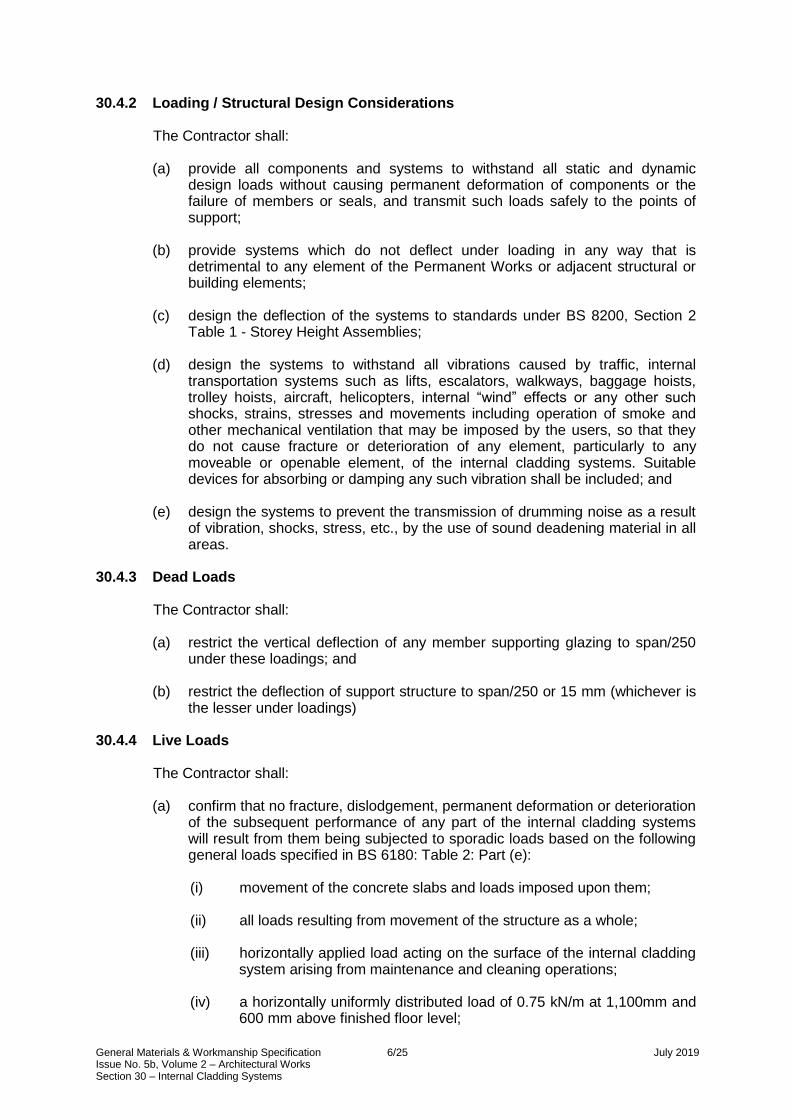
General Materials & Workmanship Specification 6/25 July 2019 Issue No. 5b, Volume 2 – Architectural Works Section 30 – Internal Cladding Systems
30.4.2 Loading / Structural Design Considerations
The Contractor shall: (a) provide all components and systems to withstand all static and dynamic
design loads without causing permanent deformation of components or the failure of members or seals, and transmit such loads safely to the points of support;
(b) provide systems which do not deflect under loading in any way that is
detrimental to any element of the Permanent Works or adjacent structural or building elements;
(c) design the deflection of the systems to standards under BS 8200, Section 2
Table 1 - Storey Height Assemblies;
(d) design the systems to withstand all vibrations caused by traffic, internal transportation systems such as lifts, escalators, walkways, baggage hoists, trolley hoists, aircraft, helicopters, internal “wind” effects or any other such shocks, strains, stresses and movements including operation of smoke and other mechanical ventilation that may be imposed by the users, so that they do not cause fracture or deterioration of any element, particularly to any moveable or openable element, of the internal cladding systems. Suitable devices for absorbing or damping any such vibration shall be included; and
(e) design the systems to prevent the transmission of drumming noise as a result
of vibration, shocks, stress, etc., by the use of sound deadening material in all areas.
30.4.3 Dead Loads
The Contractor shall: (a) restrict the vertical deflection of any member supporting glazing to span/250
under these loadings; and
(b) restrict the deflection of support structure to span/250 or 15 mm (whichever is the lesser under loadings)
30.4.4 Live Loads
The Contractor shall: (a) confirm that no fracture, dislodgement, permanent deformation or deterioration
of the subsequent performance of any part of the internal cladding systems will result from them being subjected to sporadic loads based on the following general loads specified in BS 6180: Table 2: Part (e):
(i) movement of the concrete slabs and loads imposed upon them;
(ii) all loads resulting from movement of the structure as a whole;
(iii) horizontally applied load acting on the surface of the internal cladding
system arising from maintenance and cleaning operations;
(iv) a horizontally uniformly distributed load of 0.75 kN/m at 1,100mm and 600 mm above finished floor level;

General Materials & Workmanship Specification 7/25 July 2019 Issue No. 5b, Volume 2 – Architectural Works Section 30 – Internal Cladding Systems
(v) a uniformly distributed load applied to the cladding panel of 1.0 kN/m²;
(vi) a point load of 0.50 kN applied to any part of the cladding panel;
(vii) an impact of 250 kg applied at a speed of 1.0 m/s to the buffer rail; and
(viii) other impact loads, or transferred loads, that occur during its service
life, without sustaining repairable damage;
Loads (iv), (v) and (vi) shall be separately applied.
(b) design all internal cladding to accommodate the following loadings which are different from those specified in sub-clause (a) (iv), (v) and (vi) without any reduction in performance and without permanent deformation to any component:
(i) a horizontally uniformly distributed load of 3.0 kN/m at 1,125 mm
above finished floor level, where there are protection rails;
(ii) a uniformly distributed load applied to all glazed infill panels of 1.5 kN/m²;
(iii) a point load of 1.5 kN applied to any part of the glazed infill panels;
(iv) a static load of 500 N applied horizontally through a square 100 mm
sides on any part of the framing;
Loads (i), (ii) and (iii) shall be separately applied.
All other live loads specified above in (a) shall also apply.
(c) restrict the stresses in all parts of the internal cladding systems produced by this combination of loads to the permissible stresses given in the British Standards;
(d) restrict the stresses for elements made of aluminium alloys to the permissible
stresses given in clause 4.3.1 of CP. 118;
(e) design all internal cladding systems to withstand operational forces to standards under BS 8200: Section 2 as a minimum;
(f) design and construct the internal cladding systems such that they remain rigid
and stable, and that no permanent deformation will be caused by maintenance loads, impact loads and the normal use to which they are subjected;
(g) design glass thicknesses with a safety factor of 2.5; and
(h) provide internal cladding systems’ surfaces which resist heavy impacts
generated by pedestrian traffic without noticeable change to the surface appearance, as defined by BS 8200: Section 2, Part 7.

General Materials & Workmanship Specification 8/25 July 2019 Issue No. 5b, Volume 2 – Architectural Works Section 30 – Internal Cladding Systems
30.4.5 Sound Reduction Considerations (a) Where the internal cladding totally encloses an area (with walls continuous
with ceiling and isolates the area from adjacent public area), the internal cladding systems shall achieve a sound insulation performance of no less than Rw 52, when measured on Site in accordance with BS EN ISO 140-5.
(b) The Contractor shall provide internal acoustic linings, where necessary, to
achieve such noise reduction indices;
(c) The Contractor shall submit sealants and gaskets for review without objection by the Project Manager and use them in the installation of the partitions with no noise leakage around the perimeter of the partition or at joints between individual partitions;
(d) The Contractor shall install cladding free from rattling and buzzing.
30.4.6 Impact and Abrasion Resistance
(a) The internal cladding systems shall be sufficiently hard (including glass coatings as stated in section 32.5.7) to resist heavy impacts from hand held objects and from adjacent passenger or pedestrian movements without any noticeable change to the surface appearance, as defined in BS 8200 Category B, and BS 3900 Methods of test for paints: Parts E1-12.
(b) The Internal Cladding Systems shall also resist abrasion from cleaning
methods and maintenance systems identified in the maintenance manual without any noticeable change in surface appearance.
30.5 MATERIALS 30.5.1 Materials Generally
(a) Flat, non-perforated, fully demountable, painted steel panels of varying heights and modules as indicated on the Employer’s Drawings.
(b) Flat, perforated, acoustically insulated, painted steel panels of varying
modules as indicated on the Employer’s Drawings.
(c) Special shaped, non-perforated, painted steel panels.
(d) Aluminium acoustically rated louvre panels. 30.5.2 Glass and Glazing
Refer to section 32.5.1: Glass materials generally. 30.5.3 Coatings/Treatment to Glazing System
Coatings to the glazing system shall be in accordance with section 32.5.7 (Glazing, Glazed Screens, Balustrades and Handrails).

General Materials & Workmanship Specification 9/25 July 2019 Issue No. 5b, Volume 2 – Architectural Works Section 30 – Internal Cladding Systems
30.5.4 Solid Panel Support Systems
The Contractor shall: (a) take account of the fixing zones indicated on the Employer’s Drawings, when
designing the system;
(b) provide the internal cladding systems with a supporting structure that is base fixed, with a sliding head connection to the primary structure of concrete or steel;
(c) accommodate in the Contractor’s design of the support structure as described
in the Specification, the specified construction tolerances and deflection criteria for:
(i) concrete; and
(ii) steelwork;
(d) use a modular system of components to the support structure to standardize
the relationship and details between panels, panel sub-frames and the support posts or supporting walls;
(e) prevent chemical and/or electrolytic action where dissimilar metals and/or
materials are used together. Refer to PD 6484 ‘Commentary on corrosion at bi-metallic contacts and its alleviation’. This is of particular importance where stainless steel, aluminium, and aluminium alloys are used. The Contractor shall provide the necessary insulation wherever dissimilar metals occur at interfaces with works that precede the internal cladding systems; and
(f) Hot-dip galvanize all inaccessible steel in accordance with BS 729.
30.5.5 Fixings of Internal Cladding Systems
The Contractor shall: (a) use bolts, screws, nuts and anchors of adequate strength for their designed
purpose;
(b) supply all necessary and appropriate fasteners and fixings for the internal cladding systems, associated flashings, and closures;
(c) use fixings which conform with all statutory requirements in respect of strength
and type;
(d) take adequate measures to prevent bi-metallic corrosion between dissimilar metals and to this end attention is drawn to publication PD 6484 ‘Commentary on corrosion at bi-metallic contacts and its alleviation’;
(e) use fixings within the aluminium framing which are not visible unless indicated
on the Employer’s Drawings. Restrict visible fixings to the assembly of the aluminium elements to the support steelwork using fixing types described on the Employer’s Drawings; and

General Materials & Workmanship Specification 10/25 July 2019 Issue No. 5b, Volume 2 – Architectural Works Section 30 – Internal Cladding Systems
(f) unless otherwise specified in the Specification or on the Employer’s Drawings, observe the following basic requirements:
(i) use fixings which are suited to the likely stresses, movements and
vibrations in use without allowing any wobble, creaks or deflection of any fixtures or fittings;
(ii) all panels shall be readily demountable (for easy replacement if
damaged) without compromising the integrity of the system or disturbing adjacent panels; and
(iii) make access panels removable with screw fixings and retention clips,
independently of any other panels. 30.5.6 Internal Wall Solid Panel Construction
Internal wall cladding systems solid panels shall be manufactured from steel with a minimal thickness of 1.2 mm, treated with suitable finish to provide a durable finish as specified. The back panel shall be mineral fibre acoustic material or medium density fibre board dependant on the acoustic insulation required:
(a) cladding panels shall be geometrically arranged as shown on the Employer’s
Drawings;
(b) cladding panels shall be of metal pan type construction and consist of sheet metal brake pressed folded at all four edges with a minimum return edge of 50 mm, and a radius not exceeding 3 mm. All corner folded edges shall be welded and ground smooth, prior to finishing, to form a shallow tray;
(c) all steel panels shall be fabricated from CR4 mild steel in compliance with BS
1449;
(d) glue used to bond the backing material to the metal pan shall be a single component moisture curing polyurethane adhesive;
(e) vertical joints between cladding panels shall be sealed with a serrated
compressible neoprene strip;
(f) vertical joint widths between adjacent panels shall not greater than 7 mm and not less than 5 mm wide;
(g) neoprene strips shall be straight and recessed a nominal 6 mm from the face
of the cladding panel;
(h) cladding panels shall have various cut outs at interfaces with building services installations. Size and location of cut outs shall be either shown on the Employer’s Drawings or as agreed by the Project Manager;
(i) cladding panels shall be protected against corrosion after fabrication and prior
to application of finishes;
(j) all cutting and drilling of cladding panels, and associated internal cladding systems shall take place before the application of painted finishes. Site cutting or drilling shall not be permitted except with the express permission of the Project Manager; and
(k) all exposed faces of metal shall be finished in such a way that no exposed cut
ends are left unfinished.
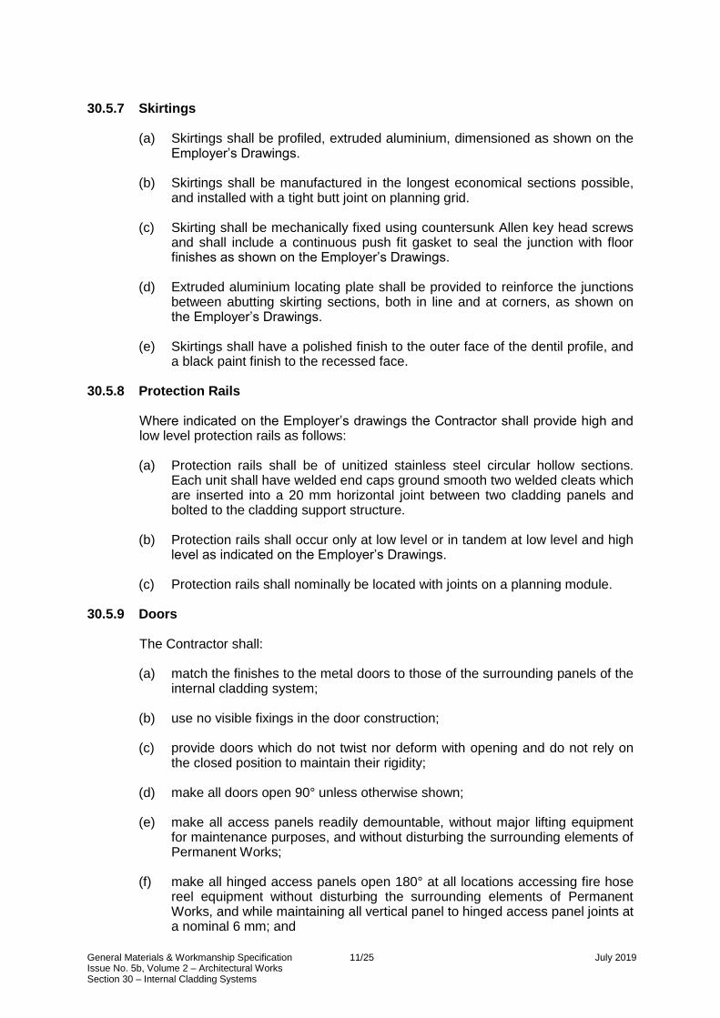
General Materials & Workmanship Specification 11/25 July 2019 Issue No. 5b, Volume 2 – Architectural Works Section 30 – Internal Cladding Systems
30.5.7 Skirtings
(a) Skirtings shall be profiled, extruded aluminium, dimensioned as shown on the Employer’s Drawings.
(b) Skirtings shall be manufactured in the longest economical sections possible,
and installed with a tight butt joint on planning grid.
(c) Skirting shall be mechanically fixed using countersunk Allen key head screws and shall include a continuous push fit gasket to seal the junction with floor finishes as shown on the Employer’s Drawings.
(d) Extruded aluminium locating plate shall be provided to reinforce the junctions
between abutting skirting sections, both in line and at corners, as shown on the Employer’s Drawings.
(e) Skirtings shall have a polished finish to the outer face of the dentil profile, and
a black paint finish to the recessed face. 30.5.8 Protection Rails
Where indicated on the Employer’s drawings the Contractor shall provide high and low level protection rails as follows: (a) Protection rails shall be of unitized stainless steel circular hollow sections.
Each unit shall have welded end caps ground smooth two welded cleats which are inserted into a 20 mm horizontal joint between two cladding panels and bolted to the cladding support structure.
(b) Protection rails shall occur only at low level or in tandem at low level and high
level as indicated on the Employer’s Drawings.
(c) Protection rails shall nominally be located with joints on a planning module. 30.5.9 Doors
The Contractor shall: (a) match the finishes to the metal doors to those of the surrounding panels of the
internal cladding system;
(b) use no visible fixings in the door construction;
(c) provide doors which do not twist nor deform with opening and do not rely on the closed position to maintain their rigidity;
(d) make all doors open 90° unless otherwise shown;
(e) make all access panels readily demountable, without major lifting equipment
for maintenance purposes, and without disturbing the surrounding elements of Permanent Works;
(f) make all hinged access panels open 180° at all locations accessing fire hose
reel equipment without disturbing the surrounding elements of Permanent Works, and while maintaining all vertical panel to hinged access panel joints at a nominal 6 mm; and

General Materials & Workmanship Specification 12/25 July 2019 Issue No. 5b, Volume 2 – Architectural Works Section 30 – Internal Cladding Systems
(g) provide door frames where shown on the Employer’s Drawings which consist of steel profiles (minimum 1.6 mm section) manufactured to comply with BS 1245 and fire check flush doors comply with BS 476 Part 31 (where shown on the Employer’s Drawings); door reveals shall be continuous with surrounding panels of same construction and finish.
30.5.10 Acoustic and Fire Rated Material
(a) The Contractor shall provide acoustic material which is inert, non-hygroscopic, rot and vermin proof, does not support fungi or bacteria and in compliance with the fire requirements specified.
(b) The mineral fibres shall be at least 3 m in diameter and not less than 200 m in length. The fibres shall be stabilised to ensure that there is no fibre migration.
(c) The material shall not shrink, slump or otherwise consolidate when installed.
30.5.11 Movement Joints
The Contractor shall: (a) provide movement and expansion joints as indicated on the Employer’s
Drawings; and
(b) design movement joints in accordance with the design intent shown on the Employer’s Drawings. The internal cladding systems shall accommodate all movement of the joint in a manner which does not compromise the panel’s integrity or appearance.
30.5.12 Gaskets
The Contractor shall: (a) butt joint all gasket-to-gasket joints. The bonding of gaskets using other
methods shall not be acceptable. The gaskets shall perform and appear as a single continuous material.
(b) Gaskets shall be either neoprene or silicone and fabricated off-Site in the
largest possible lengths leaving only the minimum fabrication on Site;
(c) where the gasket system comprises both extruded and moulded elements, make such elements perform and appear as a single element;
(d) design and select all gaskets to comply with the stipulations of BS 4255,
appropriate to the extrusion design and ensure that they do not permanently distort over the working life of the internal cladding systems;
(e) use gaskets which are free from contact with materials that have stain
characteristics, and are compatible with all substrate, sealants, and all other materials used in the internal cladding systems;
(f) provide written confirmation from the gasket manufacturer that the gasket
material and designs are suitable for their specific use in any part of the internal cladding systems, and are compatible with all other materials and sealants used within the installation;
(g) use gaskets of black colour unless otherwise specified;

General Materials & Workmanship Specification 13/25 July 2019 Issue No. 5b, Volume 2 – Architectural Works Section 30 – Internal Cladding Systems
(h) use gaskets which do not shrink, warp or deteriorate within the replacement
period specified;
(i) pre-form and factory fabricate gasket corners in ladders;
(j) select gaskets and seals to accommodate the range of dimensional tolerances and movements associated with the design, fabrication and installation of the internal cladding systems. Gasket shall be formed from materials capable of maintaining their elastic qualities and dimensions, resistant to physical and chemical attack, sufficient to maintain the acoustic performance of the internal cladding systems during its design life; and
(k) vulcanizing of gaskets shall only required where specified on the Employers
Drawings. 30.5.13 Sealants
The Contractor shall: (a) use wet applied sealants on Site only in the locations shown on the
Employer’s Drawings;
(b) use one-part silicone sealants in compliance with BS 5889;
(c) apply sealant in accordance with the supplier’s/manufacturer’s written preparatory and application procedures and the Code of Practice prepared by the United Kingdom Sealant Manufacturers’ Confederation;
(d) submit written confirmation from the sealant manufacturer confirming the
suitability of the sealant for the application intended to the Project Manager for review without objection. The period shall be stated during which the silicone shall not change in appearance or colour. Any discoloration of silicone during this time shall not be acceptable;
(e) submit proposals to the Project Manager for review without objection of the
type and colour of silicone prior to ordering;
(f) remove excess silicone and clean all joints;
(g) apply silicone evenly without bubbles and with joints not less than 6 mm x 6 mm;
(h) use sealants which are compatible with the joint surfaces and to each other,
as stated in the manufacturer’s published data or as certified by the manufacturer for each application;
(i) determine the proper hardness, compressibility or consistency of sealants in
consultation with the manufacturer, considering the joint movement and exposure for the size of joint;
(j) ensure that the silicone joints can accommodate and are compatible with any
movements to which they may be subjected;
(k) use sealant that can withstand the applicable degree of exposure to wear, abrasion and vandalism. Any sealant exposed to traffic shall have the strength and modulus to resist damage indentation;

General Materials & Workmanship Specification 14/25 July 2019 Issue No. 5b, Volume 2 – Architectural Works Section 30 – Internal Cladding Systems
(l) provide adequate protection to the silicone joints during the curing process to avoid contamination by dust and other debris; and
(m) use closed cell type backing rods which are compatible with the silicone used.
30.5.14 Louvres / Air Grilles
The Contractor shall: (a) supply and install all louvres and linear air grilles associated with and located
within internal cladding walls;
(b) install linear air grilles of extruded aluminium. They shall comprise a core within a frame, as indicated on the Employer’s Drawings. The core section shall be easily removable for access to mechanical equipment. The frame section shall be fixed back to the cladding panel support post on planning grid; and
(c) use linear air grilles for supplying air as part of the mechanical services air
conditioning system. The performance of the mechanical services shall be unaffected by the general arrangement of the proposed cladding system or by other individual components.
30.5.15 Mild Steel
The Contractor shall: (a) design all mild steel work in compliance with BS 5950: Part 1 unless otherwise
specified;
(b) use welding procedures that minimize distortion and eliminate local distortion in the final fabrication, if rectification is necessary, propose and rectify with a method reviewed without objection by the Project Manager;
(c) make no welds other than those shown on the Contractor’s Drawings that
have been reviewed and received a notice of no objection from the Project Manager, including temporary attachments or repairs. If welded temporary connections are agreed upon, their welding and removal shall be in accordance with clauses 19 and 29 of BS 5135;
(d) carry out surface preparation as follows:
(i) remove all rust, scale and surface contamination and leave a surface
equivalent in cleanliness to SA 2.5 quality of Swedish standard SIS 05-59-00 (BS 7079: Table A1);
(ii) use acid pickling for surface cleaning.
(iii) provide galvanizing in accordance with BS 729 giving a minimum
coating weight of 610 g/m²; and
(iv) post-treat steel after galvanizing if necessary, to achieve the thickness of galvanizing on the steelwork as specified.

General Materials & Workmanship Specification 15/25 July 2019 Issue No. 5b, Volume 2 – Architectural Works Section 30 – Internal Cladding Systems
30.5.16 Stainless Steel
(a) All stainless steel shall be austenitic, non-magnetic grade A151 316 S13 to BS 1449: Part 2.
(b) Material for stainless steel bolts shall be grade A151 316 S13 stainless steel
and complies with the dimensional requirements as stated in BS 3692. Bolt strength shall be equivalent to grade 4.6 bolts. Washers for stainless steel bolts shall be formed from grade 316 stainless steel.
(c) Weld metal shall be deposited by an automatic or semi-automatic process
which has mechanical properties not less than the minima specified for the weld metal deposited by electrodes complying with BS EN 499.
(d) Electrodes for metal arc welding shall be classified, coded and marked in
accordance with BS EN 499. Electrodes for manual metal arc welding shall comply with BS 2926.
(e) All visible stainless steel shall comply with BS 1449: Part 2 Table 1, type 4
and shall be satin 240 grit finished. The finish shall be established on the basis of reference samples submitted to the Project Manager for review without objection.
30.5.17 Aluminium
The Contractor shall: (a) fabricate all aluminium framing members in compliance with BS 1474;
(b) use aluminium sheeting minimum of 3mm thick and in compliance with BS
1470, BS EN 485 or BS EN 515;
(c) use only appropriate grades, strengths, and thicknesses of aluminium to meet all structural and finishing requirements. The wall thicknesses of aluminium extrusions shall be sufficient to maintain their rigidity in the lengths required in the final installation;
(d) manufacture all aluminium fixing brackets and cleats from the appropriate
grade of alloy in compliance with BS 1474. If visible, they shall be finished to match the metal panels and framing members; and
(e) protect all exposed aluminium with low tack adhesive film, which shall be
removed and disposed of by the Contractor upon Practical Completion.
General Materials & Workmanship Specification 16/25 July 2019 Issue No. 5b, Volume 2 – Architectural Works Section 30 – Internal Cladding Systems
30.5.18 Finishes: Polyester Powder Coat
(a) Where specified as a finish to metal panels and structure, polyester powder coating shall comply with BS 6496 and BS 6497, and shall be applied on an
automatic continuous paint line to a minimum thickness of 80 m and maximum thickness to match hard coating process. Colours shall be as shown on the Employer’s Drawings. One application company and one polyester powder coating supplier shall be used for the internal cladding systems.
(b) The polyester powder coating thickness between similar adjacent components
shall not vary by more than 10 m.
(c) The finish to the systems shall be in accordance with Appendix E No.6 of Table E3 of BS 5427.
(d) All powder coated panels shall receive a clear protective top coat sealant, 70
m thick.
(e) Any primer and surface treatment applied to panels and structure prior to application of decorative coatings shall have a minimum dry film thickness of
25 m and shall be compatible with the decorative coatings. Workmanship for surface preparation and paint application shall comply with BS 5493.
(f) Over-application of coatings of elements shall be avoided.
(g) All finished surfaces shall be smooth, free from blemishes, pinholes, tears,
orange peel effect and other coating defects when evenly illuminated by diffuse light and viewed using normal corrected vision from a distance of 1 m.
(h) Limits for acceptable production colour variations shall be established
between the Project Manager and the Contractor by reference to samples/ benchmarks.
30.5.19 Finishes: Aluminium Anodizing
(a) Aluminium anodizing shall comply with BS 1615 unless specified otherwise. The Contractor shall submit certification from the anodizing contractor that anodizing has been carried out in compliance with the Specification.
(b) Where aluminium is used in the internal cladding systems and the final finish
is dependent upon the base metal, the Contractor shall provide aluminium from a single batch to ensure identical chemical composition.
(c) If the quantity involved for the whole internal cladding systems is in excess of
a single batch, the Contractor shall inform and agree with the Project Manager options for the grouping of elements and components from each batch.
(d) The Contractor shall select all aluminium alloys to provide components with a
uniform finished visual appearance. The alloys shall be 6063 for extrusions and J57S for sheets.
(e) There shall be no apparent variation of final surface finish of any panels or
components when compared with each other. Panels or components, which in the opinion of the Project Manager fail to achieve a uniform final surface finish, shall be replaced.

General Materials & Workmanship Specification 17/25 July 2019 Issue No. 5b, Volume 2 – Architectural Works Section 30 – Internal Cladding Systems
(f) Where the finish is natural anodized, the Contractor shall submit samples to the Project Manager for review without objection.
(g) The thickness should be determined in accordance with BS 6161: Part 1 or
Part 2 non-destructive or BS 5411: Part 3 or Part 5 destructive. 30.5.20 Finishes: Vitreous Enamel
The Contractor shall: (a) provide vitreous enamel facing sheets in compliance with BS 3830 and BS
1344 Part 8 designated AA. Mild steel used for manufacture of vitreous enamel facing sheets shall be decarbonised “zero carbon” of flattened mild steel sheet, suitable for deep drawing application;
(b) confirm that the minimum bond strength obtained by the ground coat system
or the ground coat and cover coat system is fair to excellent as defined by the Appendix to the publication “Atlas to Enamel Defects” published by the Institute of Vitreous Enamellers 1982. “Poor” or “Bad” shall not be acceptable;
(c) provide the ground coat at the rear of the vitreous enamel facing sheet with a
bond strength in lap shear of 4 N/mm² between the ground coat and the facing sheet;
(d) spray all surfaces of the metal facing sheet with one ground coat and at least
two finishing coats of vitreous enamel;
(e) individually fire each coat of vitreous enamel and ensure uniform thickness.
The total thickness of all coats shall be between 300 and 350 m but not more
than 400 m. Units shall not be rejected if minor areas of the coat exceed 400
m, providing this does not result in the occurrence of orange peel effect, hair lining or a proneness to spalling;
(f) provide coatings to the front and rear of the sheet with a similar thickness and
a permitted tolerance of 20% in the coatings to the rear of the panel only;
(g) provide the finished vitreous enamelled units with a degree of gloss 75-85% in accordance with ASTM Test Method 34625. Gloss retention on samples taken from the production run shall not be affected when tested in accordance with BS 1344: Part 8 - Resistance to Boiling Citric Acid;
(h) provide vitreous enamel with colour achieving a stability index not less than
98.2 average colour when tested in accordance with ASTM C 538 - 64 T to colour retention with cupric sulphate;
(i) achieve a minimum acceptable image clarity of AA or A designation. Image
clarity shall be tested on samples accepted by the Project Manager by means of a distinctness of image test with a PEI - GARDNER glossmeter or similar reflectometer.

General Materials & Workmanship Specification 18/25 July 2019 Issue No. 5b, Volume 2 – Architectural Works Section 30 – Internal Cladding Systems
(j) reject vitreous enamelling if it contains any bisque damage, burn-off, carbon
boil, contamination, copperheads, crawling and tearing, crocodiling, drain lines, fish-scaling, grease marks, heat craze, lamination, excessive orange peel (in excess of agreed standards), shore lines, spilling, star marks, water lines, pop-off, sagging, as described in N.E.N. 2711. The rare occurrence of single blisters may be accepted providing the blisters do not penetrate more than a single coat of vitreous enamel. Blister penetrations shall be treated in accordance with N.E.N. 2711.
30.5.21 Colour
The Contractor shall finish colour, unless otherwise specified in the Employer’s Drawings or Specification, to the RAL reference. Exact shade shall be determined by colour match samples with a specular gloss factor of 30 % ±3 % when measured in accordance with BS 3900: Part D5, using the 60 ° geometry method.
30.6 SUBMISSIONS 30.6.1 Particulars of the Internal Cladding System
The Contractor shall submit the following particulars of the proposed internal cladding system to the Project Manager for review without objection: (a) details of the source, type and properties of the materials proposed;
(b) elevations, floor plans, sections and full size details. Details shall be fully
drawn (not outlined). Drawings shall include the following:
(i) assembly of each panel system including angles, corners, construction joints, pipe intrusions etc.;
(ii) glass and metal thickness;
(iii) metal alloy, temper and finish;
(iv) glazing materials identification;
(v) sealants and gasket identification by product name;
(vi) relative layout of walls, beams, column and slabs with dimensions
noted;
(vii) provisions for thermal movements and building movements; and
(viii) glazing details applicable to replacement glass, with outline of procedure for glass replacement.

General Materials & Workmanship Specification 19/25 July 2019 Issue No. 5b, Volume 2 – Architectural Works Section 30 – Internal Cladding Systems
30.6.2 Samples The Contractor shall provide the samples, with relevant written trade literature and specifications to the Project Manager for review without objection, which shall include but not be limited to the following: (a) 300 mm x 300 mm sample of coatings as specified to flat sheets (including
perforated panels) and extruded sections in 600 mm length (including louvre extrusion, linear air grille extrusion) - 4 no. each;
(b) all proposed gasket types in materials and colours specified. All samples shall
include at least one joint in 600 mm length - 2 no. each;
(c) all specified types of glass, samples 600 mm x 600 mm - 4 no. each;
(d) stainless steel samples 600 mm x 600 mm - 4 no. each;
(e) fixing - 4 no. each type;
(f) all fire stopping materials - 2 no. each;
(g) natural anodized aluminium skirting extrusion in 600 mm length - 2 no. each;
(h) each type of ironmongery;
(i) 300 mm x300 mm sample of vitreous enamel as specified to flat sheets - 2 no. each; and
(j) 1,000 mm section of all aluminium mullions and transoms - 2 no. each.
30.6.3 Prototypes
(a) The Contractor shall provide, maintain and/or clear away prototypes, of each internal cladding type as indicated on the Employer’s Drawings. Each prototype shall include all visible components of the various constructions, non-visible support systems and fixings.
(b) The prototypes shall utilize the specified materials and finishes of this section
and the Specification, but not necessarily the final production techniques.
(c) The prototypes shall be tested and examined in terms of quality, materials, interfacing details for accessibility by other trades, and workmanship by the Project Manager.
(d) The Contractor shall have the Project Manager witness the installation and
dismantling of the prototypes and record any variations to the agreed details on the Contractor’s Drawings.

General Materials & Workmanship Specification 20/25 July 2019 Issue No. 5b, Volume 2 – Architectural Works Section 30 – Internal Cladding Systems
30.6.4 Benchmarks
(a) The Contractor shall, following receipt of no objection from the Project Manager of relevant samples and prior to commencement of internal cladding, construct and establish one complete bay of each cladding module, as indicated on the Employer’s Drawings as benchmarks. After the Project Manager has reviewed with no objection, the benchmark shall become the standard to which all subsequent internal cladding works shall conform.
(b) In the event the Project Manager does not issue a notice of no objection for a
proposed benchmark, the Contractor shall remove and construct a new proposed benchmark before proceeding with any internal cladding works.
30.7 WORKMANSHIP 30.7.1 Tolerances
The Contractor shall:
(a) provide a high degree of accuracy in the fabrication and installation of the internal cladding systems and its support structure.
(b) at the time of completion, achieve the visual requirements of the internal
cladding systems. The allowable tolerances within any planning grid section shall be equally distributed to achieve the following requirements:
(i) wall cladding is vertical;
(ii) vertical and horizontal joints are of equal size and at equal centres;
(iii) internal cladding systems have straight lines and flat planes; and
(iv) horizontal joints are of equal size and in line between adjacent panels.
(c) perform sufficient analysis of the intended erection sequence and the overall
method statement to meet the installation tolerances stated in the Specification; and
(d) show on the Contractor’s Drawings the dimensional and detailed provisions
intended to accommodate the construction tolerances of the surrounding elements to ensure that all aspects of the internal cladding systems relate satisfactorily to the Works as a whole.
30.7.2 Tolerances for Manufacture
(a) Deviations in panel length, width and diagonal dimensions shall be restricted
to ±1 mm;
(b) The cladding panels shall appear smooth and flat in accordance with the reviewed benchmark. The required flatness criterion shall be 1:1,000; and
(c) All return edges of steel panels shall have a minimum external bending radius
of 1.5 mm and a maximum of 3 mm. The Contractor shall confirm the radius, which shall be consistent throughout the internal cladding systems.

General Materials & Workmanship Specification 21/25 July 2019 Issue No. 5b, Volume 2 – Architectural Works Section 30 – Internal Cladding Systems
30.7.3 Installation Tolerances
The Contractor shall: (a) erect the internal cladding systems in proper alignment in relation to
established lines and grades as shown on the Employer’s Drawings and take account of the installation tolerance requirements of the internal cladding system such that units are accurately located, relative to grid lines;
(b) restrict the average width deviation of any joint from the nominal width to ±1
mm. Any variation shall be equally distributed with no sudden changes or steps;
(c) restrict the maximum variation in plan location from the planning grid of any
part of the cladding system to ±2.0 mm;
(d) restrict the maximum variation in height of any part of the internal cladding system from given datum to ±2.0 mm;
(e) restrict the maximum offset in plan, level or section between any two adjacent panels to ±1.0 mm; and
(f) make cut outs for interfacing works to the dimensions shown on the
Employer’s Drawings or agreed on Site to ±1 mm. 30.7.4 Glass Tolerances
(a) Manufactured glass sizes shall be ± 1 mm on each straight length.
(b) Lipping of laminated glass edges shall be 1 mm.
(c) After final processing the deviation in flatness at any peak shall be restricted to 0.13 mm and the difference between adjacent peaks to 0.08 mm. Where bow tolerance and wave tolerance differ, the stricter requirements shall prevail. Direction of ripples shall be consistent.
(d) The Contractor shall submit a detailed list of tolerances to which the internal
cladding Systems are fabricated and installed for review without objection by the Project Manager. As a minimum, this shall include the following:
(i) position on plan;
(ii) level;
(iii) alignment;
(iv) joints between panels;
(v) diagonal;
(vi) eccentricity; and
(vii) inclination.

General Materials & Workmanship Specification 22/25 July 2019 Issue No. 5b, Volume 2 – Architectural Works Section 30 – Internal Cladding Systems
30.7.5 Louvres and Linear Air Grilles The Contractor shall: (a) make linear air grilles continuous with 2 mm joints at centres to match
cladding modules;
(b) provide suitable fasteners to align separate sections of linear air grille. When installed, linear air grilles shall present a continuous straight appearance without misalignment or distortion;
(c) mitre and factory fabricate all linear air grille corners; and
(d) fit sections of linear air grilles not connected to plenums or ductwork with a
non-visible air boot, blanking plate or similar in natural silver anodized aluminium.
30.8 INSPECTION, TESTING AND COMMISSIONING 30.8.1 Durability Tests
The Contractor shall: (a) test corrosion resistance in accordance with BS 5466: Part 3, for a period of 8
hours with results evaluated in accordance with BS 3745. The rating shall be a minimum of 8;
(b) test light resistance in accordance with BS 6161: Part 7. The rating shall be a
minimum of 9;
(c) test ultra violet resistance in accordance with BS 6161: Part 8;
(d) test heat resistance in accordance with BS 1615: Clause 9.3;
(e) test abrasive resistance in accordance with BS 6161: Part 9 and 10; and
(f) carry out each of the above tests at the rate of one test per 2,000 m² of panel. 30.8.2 Impact Tests
The Contractor shall: (a) test the impact resistance of the protection rail by subjecting it to the impact
force of 250 kg at a speed of 0.9 m/s at mid-span. The buffer rail shall withstand such impact without permanent deformation or permanent indentation. The test shall be carried out at 200 m intervals;
(b) test the impact resistance of the panel surfaces to verify that they can
withstand heavy impacts generated from pedestrian traffic without any permanent scuffing, deformation or indentation in excess of 1 mm in depth. The impact resistance test for the panel surfaces shall comply with BS 8200 Appendix G assuming performance category B as described in Table 2. The test shall be carried out on one panel per two hundred, randomly selected from the largest panels;

General Materials & Workmanship Specification 23/25 July 2019 Issue No. 5b, Volume 2 – Architectural Works Section 30 – Internal Cladding Systems
(c) test the scratch resistance of the panel coating in accordance with BS 3900 part E2. There shall be no penetration to the substrate under a load of 0.5 kg. The test shall be carried out on one panel per two hundred, randomly selected from the largest panels;
(d) test the impact resistance of the panels in accordance with BS 3500: Part E3.
The maximum permissible indentation shall be 1.0 mm. The test shall be carried out on one panel per two hundred, randomly selected from the largest panels;
(e) test the resistance to separation from the substrate of the panel coating in
accordance with BS 3900 part E6 using a single blade tool. The coating shall comply with Classification 0 of Table 1 of BS 3900 part E6. One such panel in every two hundred shall be tested using this method; and
(f) provide details of tests to demonstrate the performance of materials and
finishes in resisting impact from pedestrian traffic (hands, rings, luggage, trolleys, cloth, shoes, etc.) and any other impacts resulting from adjacent traffic movements.
30.8.3 Acoustic Tests
The Contractor shall: (a) test samples of the internal cladding systems (glazed and non-glazed) to
verify fulfillment of the acoustic performance requirements specified. The samples shall represent the materials used in the systems and include at least one horizontal joint and one vertical joint;
(b) commence the acoustic tests at times agreed with the Project Manager with
results being submitted in writing to the Project Manager within three weeks of completion of the tests;
(c) calculate the acoustic ratings specified from BS 5821: Part 1: 1984 from test
measurements of sound reduction index in accordance with BS 2750: Part 3: 1980. Such tests shall be obtained from an independent acoustic laboratory, whose qualifications and abilities have been previously reviewed without objection by the Project Manager and shall represent full height section of the internal cladding systems including panel, junction joints and, where appropriate, doors; and
(d) obtain acoustic ratings and measurements in accordance with ISO or DIN or
other recognized standards equivalent to British Standards to the satisfaction of the Project Manager.

General Materials & Workmanship Specification 24/25 July 2019 Issue No. 5b, Volume 2 – Architectural Works Section 30 – Internal Cladding Systems
30.8.4 Tests for Finishes to Aluminium
The Contractor shall test finished aluminium panels and extrusions to the following in addition to those specified above. Test specimens shall be at least 150 mm long and 75 mm wide with a flat-coated surface on which to conduct instrument measurements. The Contractor shall label the test specimens to indicate exposed surfaces. Tests shall comply with AAMA 605.2-1980 as outlined by the following: (a) Hardness - Pencil: The finish shall achieve a minimum rating of F in
accordance with AAMA 605.7.3;
(b) Film Adhesion: The finish shall achieve excellent ‘Knife’ adhesion;
(c) Impact Resistance: There shall be no removal using a Gardener Variable Impact Tester as AAMA 605.7.5;
(d) Abrasion Resistance: The finish shall achieve an abrasion coefficient value of
20 minimum according to AAMA 605.7.6;
(e) Acid Resistance: Using the Muriatic Acid Spot Test the finish shall not show any signs of attack after 15 minutes as AAMA 605.7.7.1;
(f) Resistance to Acid Pollutants: The finish shall not achieve more than 5E Units
(NBS) as stipulated in AAMA 605.7.7.3;
(g) Pollutants: Colour change shall be calculated in accordance with ASTM-D-2244;
(h) Detergent Resistance (3%) immersion at 100°F: The finish shall not show any
signs of attack after 72 hours in accordance with AAMA 605.7.7.4;
(i) Humidity Resistance 100% Relative Humidity at 100°F: The finish shall have fewer than eight blisters after 3000 hours of exposure in accordance with AAMA 605.7.8.1;
(j) Salt Spray Resistance 5% salt at 100°F: The finish shall have 1.5mm
maximum undercutting after 3000 hours of exposure in accordance with AAMA 605.7.8.2;
(k) Colour Retention (ASTM-D-2244): The finish shall have a maximum of 5E
Units (NBS) colour change after 5 years of exposure in accordance with AAMA 605.7.9.1.2;
(l) Chalk Resistance: The finish shall not have any more chalking than that
represented by a No.8 rating for colours and a No.6 rating for whites after 5 years of exposure in accordance with AAMA 605.7.9.1.3;
(m) Sealant Compatibility: No deleterious effects to the coating shall occur in
accordance with AAMA 605.7.10;
(n) Alkali Resistance (Mortar Pat): The finish shall not show any signs of attack after 24 hours in accordance with AAMA 605.7.7.2; and
(o) Erosion: The finish shall not suffer a loss greater than 20% after 5 years of
exposure in accordance with AAMA 605.7.9.1.5.

General Materials & Workmanship Specification 25/25 July 2019 Issue No. 5b, Volume 2 – Architectural Works Section 30 – Internal Cladding Systems
30.9 OPERATIONS AND MAINTENANCE 30.9.1 Demountability
The Contractor shall ensure that all visible elements of the internal cladding systems are interchangeable and removable for purposes including maintenance.
30.9.2 Maintenance and Repair: Primary Components
The Contractor shall ensure that primary components have a predicted service life not less than 12 years without the need for maintenance and other than regular cleaning. The following components shall be primary components:
(a) all framing and structural support components;
(b) glass;
(c) panels; and
(d) fixings.
30.9.3 Maintenance and Repair: Secondary Components
(a) The following are secondary components which shall have a service life of not less than 8 years:
(i) gaskets and compression seals; and
(ii) sealants.
(b) The Contractor shall state the predicted service life of all secondary components and provide guidance on the required maintenance, replacement periods, and methods of replacement. Secondary components shall be capable of easy replacement without compromising the structural or visual integrity of the internal cladding systems. Components shall be capable of replacement without progressive dismantling of the internal cladding systems.
30.9.4 Operation and Maintenance Manual
The Contractor shall provide an Operation and Maintenance Manual including, but not limited to:
(a) Details of all cladding systems used;
(b) Drawings showing the extent of each type of cladding system;
(c) Particulars of materials manufacturers;
(d) Means of safe access for cleaning and maintenance;
(e) Procedures for changing panels and other typical components; and
(f) Recommendations for cleaning and maintenance.

[this page not used]

General Materials & Workmanship Specification 1/14 July 2019 Issue No. 5b, Volume 2 – Architectural Works Section 31 – Carpentry & Joinery
SECTION 31 CARPENTRY AND JOINERY 31.1 GENERAL
This section provides detailed technical requirements in respect of carpentry and joinery which generally comprise:
(a) hardwood and softwood timber;
(b) plywood and veneered plywood;
(c) block board;
(d) hardboard;
(e) chipboard;
(f) medium density fibre board (MDF);
(g) high density fibreboard (HDF);
(h) laminates;
(i) fixings;
(j) adhesives; and
(k) preservatives
The materials specified below shall comply with the sections stated, unless otherwise stated in this section: (l) linings, sheathings, dry wall partitions and toilet cubicles refer to section 33;
(m) suspended ceilings refer to section 34;
(n) ironmongery refer to section 36; and
(o) painting and decorating refer to section 40.
31.2 NOT USED

General Materials & Workmanship Specification 2/14 July 2019 Issue No. 5b, Volume 2 – Architectural Works Section 31 – Carpentry & Joinery
31.3 RELEVANT CODES AND STANDARDS
The Standards and Codes of Practice specified in this section are listed below for information only. The Contractor shall comply with the edition of the Standard or Code of Practice listed in the text when stated, or the latest edition when no edition is listed. Where British Standards have been replaced by the new BS EN documents, the old BS number is retained in the text with the new BS EN number listed below.
BS 144 Specification for coal tar creosote for wood preservation
BS 476 Fire tests on building materials and structures
BS 1088: Part 1 Marine plywood. Requirements
BS 1088: Part 2 Marine plywood. Determination of bonding quality using the knife test
BS 1186: Parts 1 and 2 (replaced by BS EN 942 7 & BS 1186-2)
Timber in joinery
BS 1202: Part 1 Steel nails
BS 1203 Hot-setting phenolic and aminoplastic wood adhesives. Classification and test method
BS 1204 Parts 1 and 2 (replaced by BS EN 301 & BS EN 302)
Adhesives, phenolic and aminoplastic, for load-bearing timber structures
BS 1282 (replaced by BS 8417+A1)
Preservation of wood. Code of practice
BS 5669: Parts 1 and 2 (replaced by BS EN 309 & BS EN 311 & BS EN 317 & BS EN 323 & BS EN 324 & BS EN 312 & BS EN ISO 12460)
Particleboards and wood-based panels
BS 6206 Impact performance for safety glass
BS 6566 (replaced by BS EN 636+A1 & DD CEN/TS 1099)
Plywood
BS EN 438 Decorative laminate sheets
BS EN 622-1 Fibreboards. Specifications. General requirements
BS EN 622-2 Fibreboards. Specifications. Requirements for hardboards
BS EN 622-3 Fibreboards. Specifications. Requirements for medium boards
BS EN 622-4 Fibreboards. Specifications. Requirements for softboards
BS EN 622-5 Fibreboards. Specifications. Requirements for dry process boards (MDF)

General Materials & Workmanship Specification 3/14 July 2019 Issue No. 5b, Volume 2 – Architectural Works Section 31 – Carpentry & Joinery
BS EN 1382 Timber Structures. Test methods. Withdrawal capacity of timber fasteners.
BS EN 1383 Timber structures. Test methods. Pull through resistance of timber fasteners.
PNAP ADV-5 Tropical Hardwood Timber – Practice Notes for Authorized Persons, Registered Structural Engineers and Registered Geotechnical Engineers – Part C Advisory
31.4 NOT USED
31.5 MATERIALS 31.5.1 Timber Generally
(a) Timber shall generally comply with BS 1186: Part 1 and shall be of mature growth, properly seasoned and sawn square.
(b) Timber shall be free from wood wasp holes, large loose or dead knots, splits
or other defects that will reduce its strength.
(c) Pin holes and worm holes shall be permitted subject to the review without objection by the Project Manager provided that there is no active infestation of the timber, the strength of the member is not impaired and they do not appear on the finished faces of joinery work.
31.5.2 Timber for External Use
(a) Timber shall be either hardwood or softwood suitable for external use.
(b) Softwood shall be Radiata Pine from New Zealand, and Red or White Pine from Canada.
(c) Temperate Hardwoods shall be Beech or China Oak. Species shall be
submitted to the Project Manager for review without objection.
(d) The Contractor shall obtain timber either softwood or hardwood from a sustainable forest or plantation.
(e) The Contractor shall submit an authenticated certificate form Forest
Stewardship Council (FSC) or other approved authority.
(f) Moisture content shall be in accordance with section 31.8.1 and the specified moisture content of timber shall be maintained until preservative treatment described below is applied.
(g) Clear colourless copper chrome arsenic in compliance with B2 4072 or other
preservative previously reviewed without objection by the Project Manager shall be used.
(h) Tropical hardwood including Meranti, Iroko Sapele, Angre. Mahongony, Teak
and Ramin, shall not be used unless obtained from the Forest Stewardship Council (FSC) certified forests.

General Materials & Workmanship Specification 4/14 July 2019 Issue No. 5b, Volume 2 – Architectural Works Section 31 – Carpentry & Joinery
31.5.3 Softwood
(a) Softwood for carpentry shall be Pine, Cedar, Spruce or China fir or other species reviewed without objection by the Project Manager.
(b) All timber shall be appropriately stamped or marked to identify origin and
grade.
(c) All timber shall be kiln dried and vacuum impregnated to New Zealand Standard H3, or equivalent, with copper chrome arsenate, or as directed otherwise by the Project Manager.
(d) All softwood shall be from a verifiable sustainable forest and shall be
accredited with a certificate from the Forest Stewardship Council (FSC). 31.5.4 Hardwood
(a) Hardwood shall only be used in special circumstances under the direction of the Project Manager, and shall be certified as originating from a sustained resource or managed plantation as certified by the Forest Stewardship Council (FSC) or other approved authority. Consideration must be given to the provisions of PNAP ADV-5and further Practice notes for Authorized Persons restricting the use of Hardwoods.
(b) Density of hardwood shall be 720 kg/m3 (minimum) at 15% moisture content.
(c) The Contractor shall submit the following information to the Project Manager
for review:
(i) the species and country of origin;
(ii) the name of the concessions or plantations form which these timbers originate;
(iii) copies of the forestry policies implemented by these concessions or
plantations which confirm that the management of the timber resource is sustainable;
(iv) shipping documents which confirm that the supplier in Hong Kong has
obtained the timber form the stated concessions or plantations;
(v) certificate form the Forest Stewardship Council (FSC) or other approved authority,
(d) Hardwood of unknown species or from unidentified sources shall not be used.

General Materials & Workmanship Specification 5/14 July 2019 Issue No. 5b, Volume 2 – Architectural Works Section 31 – Carpentry & Joinery
31.5.5 Plywood
(a) Plywood shall comply with BS 6566 and of the following grades, as specified:
(i) "Grade 1 veneer" - hardwood faced, as specified, for natural finish.
(ii) "Grade 2 veneer" - luan faced for painting.
(b) Bonding adhesive between veneers shall be resin adhesive classified as moisture and weather resistant (M.R.) in BS 1203.
(c) Nominal standard thicknesses of plywood shall be 3, 4, 5, 6, 9, 12, 15, 18 and
25 mm.
(d) Plywood containing hardwoods of unknown species or from unidentified sources shall not be used. Only plywood made from softwood or temperate hardwoods that originate form the Forest Stewardship Council (FSC) certified forests or other approved authority (e.g. Douglas Fir or Birch).
31.5.6 Marine Plywood
Marine plywood shall comply with BS 1088 and 4079 bonded with Type weatherproof and boil-proof (W.B.P.) adhesive between plys.
31.5.7 Blockboard
Blockboard shall be Grade 2 veneer for painting, and bonded with Type M.R. adhesive as in section 31.5.4.
31.5.8 Hardboard
Hardboard shall comply with BS EN 622 Part 2: 1997: "Standard" (Types SHA, SHB and SHC) or "tempered" (Type THE and THN) as specified.
31.5.9 Insulating Board
Insulating board (Soft board) shall comply with BS EN 622 Part 4: 1997. 31.5.10 Wood Chipboard
(a) Wood chipboard shall be unsanded or sanded board in compliance with BS 5669: Part. 1 & 2. Veneered chipboard shall be a proprietary brand reviewed without objection by the Project Manager. Melamine-faced chipboard shall comply with BS 7331: 1990.
(b) All wood chipboards shall be low formaldehyde emission chipboard (Class El)
unless otherwise permitted by the Project Manager, or polyurethane - based chipboard with zero formaldehyde emission. Any boarding to be used in wet areas such as kitchens shall be high moisture resistant board in compliance with BS EN 622: 1997.

General Materials & Workmanship Specification 6/14 July 2019 Issue No. 5b, Volume 2 – Architectural Works Section 31 – Carpentry & Joinery
31.5.11 Glass Fibre Insulating Quilt
Glass fibre insulating quilt shall be lightweight-bonded mat weighing 12 kg/m2
uncompressed.
31.5.12 Semi-rigid Glass Fibre Slab
Glass fibre insulating board shall be semi-rigid resin-bonded glass fibre weighing 45-48 kg/m3.
31.5.13 Medium Density Fibreboard (MDF)
Medium Density Fibreboard shall be moisture resistant grade (MDFMR) with density in excess of 600 kg/m3 in compliance with BS EN 622 Part 5: 1997.
31.5.14 Laminated Plastic
Laminated plastic sheet shall be BSEN 438 Class HG (Horizontal- General Purpose) or VG (Medical-General Purpose) or FR grade (0.8 mm complying with class 0/1 spread of fame) as specified.
31.5.15 Nails
(a) Nails shall be steel nails in compliance with BS 1202: Part 1, with "bright" finish, unless otherwise specified.
(b) Nail lengths shall be not more than the total thickness of sections to be joined
less 5 mm, or not less than twice the thickness of section through which nails are driven.
(c) Where the thickness of the outer section through which nails are being driven
is less than half of the section to which nailing is being done, the depth of penetration of the nails into the latter shall be not less than 10 diameters of the nails being used.
31.5.16 Screws
(a) Wood screws shall be brass, stainless steel, alloy or other non-corroding metal in compliance with BS 1210 with countersunk heads, unless otherwise specified. Steel screws shall only be used for Temporary Works. Screws shall be used for all particleboard fixing.
(b) Screw lengths shall be not more than the total thickness of sections to be
joined, less 5 mm, or not less than one and a half times the thickness of section through which screws are driven.
(c) Where the thickness of the outer section being screwed is less than half that
of the section to which screwing is being done, the depth of penetration of the screwing into the latter shall be not less than the thickness of the outer section.
(d) Screw cups shall be brass cups or stainless steel.

General Materials & Workmanship Specification 7/14 July 2019 Issue No. 5b, Volume 2 – Architectural Works Section 31 – Carpentry & Joinery
31.5.17 Masonry Nails
The Contractor shall not use masonry nails or drive pins without the express permission of the Project Manager.
31.5.18 Explosive Cartridges
(a) The Contractor shall obtain a notice of no objection from the Project Manager before using explosive cartridge operated fixings. All fixings shall be in accordance with the Factories and Industrial Undertakings (Cartridge-Operated fixing tools) Regulations.
(b) The Contractor shall use tools, normally of the indirect acting type, plus pins
and cartridges in accordance with the manufacturer's recommendations.
(c) A tool shall only be used by a person holding a certificate of competency, specifying the maker and model of the tool on which he has been successfully trained.
31.5.19 Plugs
(a) Plugs for fixing to hard materials shall be proprietary plugs of plastic, soft metal, fibre or similar.
(b) Fixing to friable materials, plasterboard and the like shall be proprietary fixings
specially designed for that situation and reviewed without objection by the Project Manager.
(c) The use of wood plugs shall not be permitted.
31.5.20 Adhesive
(a) Adhesive for wood shall be as follows:
(i) for internal use - synthetic resin adhesive classified as moisture resistant and moderately weather-resistant (M.R.) in BS 1204: Part. 1;
(ii) for external use or internal use under very damp conditions - synthetic
resin adhesive classified as weatherproof and boil-proof (W.B.P.) in BS 1204: Part. 1.
(b) Adhesive for fixing laminated plastic sheet shall be synthetic resin adhesive
classified as weather-proof and boil-proof (W.B.P.) in BS 1204: Parts 1 and 2.
(c) Where the temperature exceeds 25 oC, a "warm-setting" grade of adhesive shall be used.
(d) The use of animal glues shall not be permitted.
31.5.21 Resin for MDF Panels
All urea formaldehyde bonded MDF panels and MUF mouldings shall be manufactured with low emission resins conforming to European E1 emission standard 9 mg/100 g (minimum).

General Materials & Workmanship Specification 8/14 July 2019 Issue No. 5b, Volume 2 – Architectural Works Section 31 – Carpentry & Joinery
31.5.22 Wood Preservative
Wood preservative shall be a proprietary brand of exterior grade.
31.5.23 Wood Preservative for External Timber:
(a) Timber shall be free from dirt and surface moisture.
(b) The Contractor shall apply preservative by pressure impregnation in accordance with BS 1282:1997.
(c) The Contractor shall apply preservative in a manner that is not hazardous to
health and adhere strictly to the manufacture’s instructions.
(d) The Contractor shall complete all cutting, planning, borings, drilling, notching or any other machining or manual operation prior to preservative treatment.
(e) For certain timbers such as Douglas Fir, which are difficult to impregnate, the Contractor shall make 20 mm deep incisions coverage of 650 per m2 in the direction of the grain in accordance with BS 144:1997. This method shall only be used in timber sections exceeding 80mm thickness.
(f) For timber where impregnation is not suitable and a paint finish is not required,
the Contractor shall apply 2 coats of creosote previously reviewed without objection by the Project Manager in accordance with the manufacturer’s instructions
31.6 SUBMISSIONS 31.6.1 Particulars of Carpentry and Joinery
The following particulars of the proposed carpentry and joinery shall be submitted to the Project Manager for review without objection: (a) Contractor’s Drawings showing the fabrication details of all custom made
joinery;
(b) certification confirming that all timber proposed originates from a sustained renewable resource or managed plantation and that the timber complies with the requirements stated in the Specification and including results of tests for;
(i) density, and
(ii) moisture content; and
(c) manufacturer’s literature of all proprietary carpentry and joinery.

General Materials & Workmanship Specification 9/14 July 2019 Issue No. 5b, Volume 2 – Architectural Works Section 31 – Carpentry & Joinery
31.6.2 Samples and Prototypes
The following samples of proposed materials together with the particulars referred to above shall be submitted to the Project Manager for review without objection: (a) samples of all types of timber for joinery where the grain is to be left exposed
or where the surfaces are to be varnished or similarly treated;
(b) a sample taken from each batch of timber in accordance with section 31.8.2; and
(c) prototypes of each type of repetitive custom joinery before starting fabrication.
31.6.3 Benchmarks
(a) The Contractor shall, following receipt of no objection from the Project Manager of relevant samples and prior to commencement of carpentry and joinery construct one complete module of each type of carpentry and joinery as benchmarks. Upon a notice of no objection, the benchmarks shall become the agreed standard to which all subsequent carpentry and joinery shall conform.
(b) In the event the Project Manager does not issue a notice of no objection for a
proposed benchmark, the Contractor shall remove and construct a new proposed benchmark before proceeding with any carpentry and joinery works.
31.7 WORKMANSHIP 31.7.1 Storage
The Contractor shall store timber in a dry, well ventilated place and protect from the weather.
31.7.2 Workmanship Generally
(a) Workmanship generally shall be in compliance with BS 1186: Part 2.
(b) The Contractor shall plug and screw or secure timber sections to the backing by means previously reviewed without objection by the Project Manager.
(c) The Contractor shall check location of buried services before fixing to walls
and other surfaces. 31.7.3 Timber
The Contractor shall cut timber to required sizes and lengths as soon as practicable after commencement of installation and store the timber in a dry, well-ventilated and under cover area.
31.7.4 Dimensions
(a) Dimensions of sections shown on the Employer’s Drawings are finished sizes. The Contractor shall allow for planing and sanding faces to finished sizes.
(b) The Contractor shall verify Site dimensions before prefabricating joinery
fittings.

General Materials & Workmanship Specification 10/14 July 2019 Issue No. 5b, Volume 2 – Architectural Works Section 31 – Carpentry & Joinery
31.7.5 Planed Timber
The Contractor shall plane timber for joinery on all faces; finish exposed faces to a fine glass papered surfaces and round arises to 1 mm radius.
31.7.6 Framed Joinery Generally
(a) Faces of framed joints shall be square and driven together to give a close, accurate fit.
(b) The Contractor shall prepare and frame up joinery work with dry joints and
store until required for fixing.
(c) Before fixing joints, the Contractor shall put together with white glue and wedge up. Replace any sections that have warped or developed shakes or other defects.
31.7.7 Running Bonded Joints
Running bonded joints shall be cross-tongued. For work over 40 mm thick, double tongues shall be used.
31.7.8 Joinery with Clear Finish
Joinery with clear finish shall be protected from damage or discolouration. The Contractor shall submit proposals for protection to the Project Manager for review without objection.
31.7.9 Nailing The Contractor shall: (a) nail timber sections securely to the backing without splitting the timber;
remove and replace any split timbers;
(b) punch nail heads below timber surfaces visible in completed work; and
(c) nail weather boarding to wood farming with not less than two corrosion proofed nails in the width of each board at each framing member.
31.7.10 Screwing
The Contractor shall: (a) when specified, screw timber sections to the backing including drilling pilot
holes and countersinking heads flush with timber surfaces;
(b) insert screws in full depth with a screwdriver and not hammered;
(c) leave countersink screw heads 5 mm (minimum) below timber surfaces with natural finish; and
(d) glue in pellets cut from timber with matching colour and grain; finish off flush
with face.

General Materials & Workmanship Specification 11/14 July 2019 Issue No. 5b, Volume 2 – Architectural Works Section 31 – Carpentry & Joinery
31.7.11 Wood Preservative
The Contractor shall apply wood preservative to all concealed surfaces of timber including framing, fillets, backs of frames, skirtings etc.
31.7.12 Moisture Content
The Contractor shall not fix laminated plastic sheet to timber with a moisture content of more than 16%.
31.7.13 Doors and Frames Generally Templates or formers shall be used for door opening construction. Proprietary doors sets shall not be used as former. Door frames shall not be used as formers except with the express permission of the Project Manager.
31.7.14 Flush Doors
(a) Stiles and rails generally shall be 75 mm wide. For doors exceeding 900 mm wide or 2,000 mm high, stiles shall be 100 mm wide.
(b) Infill for hollow core doors shall be 20 mm horizontal battens at 150 mm centres. The Contractor shall install stiffener for lock fixing, door closers, or other ironmongery as specified, or composition board core reviewed without objection by the Project Manager.
(c) Infill for solid core doors shall be 25 mm vertical battens tightly cramped
together with the covering fully bonded on both sides.
(d) Cover both sides of the door with one of the following as shown on the Employer’s Drawing:
(i) 5 mm plywood for painting;
(ii) 5 mm selected hardwood faced plywood for clear finish;
(iii) Class HG laminated plastic bonded to 5 mm plywood; or
(iv) other board finish reviewed without objection by the Project Manager.
(e) The Contractor shall provide 12 mm selected hardwood lipping pinned and
glued to all edges.
(f) Lipping to meeting edges of folding doors and meeting edges and heels of swinging doors shall be 25 mm thick rebated or rounded.
(g) When specified, the Contractor shall fit the bottom edge of doors with a 12 mm
selected hardwood removable carpet/finishes strip screwed to the lipping.

General Materials & Workmanship Specification 12/14 July 2019 Issue No. 5b, Volume 2 – Architectural Works Section 31 – Carpentry & Joinery
31.7.15 Cupboards/ Custom Joinery The Contractor shall:
(a) construct cupboard doors as follows, unless otherwise stated:
(i) plywood or blockboard lipped on all edges with selected hardwood faced
with laminated plastic sheet or prepared for painting; or
(ii) hollow core doors; and
(iii) melamine faced on both sides and lipped chipboard.
(b) construct drawers with 20 mm thick front, 15 mm thick back and sides, dovetailed and framed together and 5 mm thick bottom housed on three sides;
(c) set drawers to slide on proprietary runners; and
(d) submit ironmongery for review without objection by the Project Manager.
31.7.16 Openings in Flush Doors
The Contractor shall frame openings with 12 mm (minimum) selected hardwood lipping and rebate lipping for glazing, if required.
31.7.17 Glazing Beads
The Contractor shall provide glazing beads to match surrounding timber; mitre at angles; fix with screws and cups, where specified. Glazing beads shall not be less than 12 mm thick.
31.7.18 Half hour Fire Resisting Doors
(a) Half-hour fire doors shall be 50 mm solid core flush door, and shall be certified as having been tested in accordance with BS 476.
(b) Vision panels shall be fire resisting safety glass complying with BS 476 part 22
and BS 6206
(c) Hinges with nylon bearings shall not be used in fire-resisting door assemblies. 31.7.19 One hour Fire Resisting Doors
(a) One hour fire doors shall be proprietary fire doors previously reviewed without objection by the Project Manager and tested in accordance with BS 476: Part. 20-23.
31.7.20 Smoke and Intumescent Seals
Fire rated doors shall incorporate proprietary smoke seals and intumescent strips in compliance with BS 476: Part. 20-23.

General Materials & Workmanship Specification 13/14 July 2019 Issue No. 5b, Volume 2 – Architectural Works Section 31 – Carpentry & Joinery
31.7.21 Acoustic Doors
Acoustic doors shall be solid core doors with air-tight seals at junctions with the door frames and threshold. The overall door configuration shall achieve a sound insulation performance no less than STC 51 when tested under laboratory conditions in accordance with ASTM E90 and determined according to ASTM E413.
31.7.22 Fixing of Frames The Contractor shall:
(a) construct door frames with properly framed joints and fix, using cramps or
bolts and secure the bottom of door frames with dowels as specified in section 36; and
(b) bed frames in cement mortar, leaving no gaps;
(c) for external doors, rake out external face 10 mm deep, and point with a
sealant previously reviewed without objection by the Project Manager. 31.7.23 Architraves
Architraves shall be one length between angles. The Contractor shall mitre architraves at angle joints.

General Materials & Workmanship Specification 14/14 July 2019 Issue No. 5b, Volume 2 – Architectural Works Section 31 – Carpentry & Joinery
31.8 INSPECTION, TESTING AND COMMISSIONING 31.8.1 Moisture Content of Timber
The Contractor shall calculate moisture content at the time of fabrication by the following formula:
Wet (or supplied) Mass – Dry Mass x100 = Moisture Content (percentage) Dry Mass
(a) The dry mass shall be determined by drying in an oven at a temperature of
103 oC ± 2 oC until the weight is constant.
(b) The maximum permissible moisture content in timbers to be incorporated into the Works shall be as follows: -
(i) internal timber for use in air conditioned space 12%;
(ii) internal timber generally 16%;
(iii) timbers with one face to the exterior of the building and one face to the
interior 18%;
(iv) external timbers (e.g. fencing etc.) 20%.
31.8.2 Testing Timber
(a) Each sample of timber shall be tested to determine the moisture content at the time of fabrication.
(b) The moisture content at the time of fabrication shall be calculated from the
above equation.
(c) A batch of timber is any quantity of timber of the same type and grade, from the same source, covered by the same certificates and delivered to the Site at any one time.
(d) 1 sample of timber shall be provided from each batch of timber.
(e) The size of each sample shall be 1000 mm x 50 mm x 50 mm.

General Materials & Workmanship Specification 1/15 July 2019 Issue No. 5b, Volume 2 – Architectural Works Section 32 – Glazing, Glazed Screens, Balustrades & Handrails
SECTION 32 GLAZING, GLAZED SCREENS, BALUSTRADES AND HANDRAILS 32.1 GENERAL
This section provides detailed technical requirements in respect of the glazing, glazed screens, balustrades and handrails which generally comprise: (a) glass generally for internal use;
(b) internal glazed screens;
(c) glass balustrades and associated metal balustrades (when forming part of an
overall system);
(d) toughened glass balustrades to edges of voids;
(e) cantilevered structural glazed balustrades;
(f) Other metal balustrades are specified in section 35 (Architectural Metalwork)
The materials specified below shall comply with the sections stated, unless otherwise stated in this section:
(g) curtain walling refer to section 29;
(h) internal cladding refer to section 30;
(i) carpentry and joinery refer to section 31;
(j) linings, sheathings, drywall partitions and toilet cubicles refer to section 33;
(k) architectural metalwork refer to section 35; and
(l) ironmongery refer to section 36.
32.2 NOT USED

General Materials & Workmanship Specification 2/15 July 2019 Issue No. 5b, Volume 2 – Architectural Works Section 32 – Glazing, Glazed Screens, Balustrades & Handrails
32.3 RELEVANT CODES AND STANDARDS
The Standards and Codes of Practice specified in this section are listed below for information only. The Contractor shall comply with the edition of the Standard or Code of Practice listed in the text when stated, or the latest edition when no edition is listed. Where British Standards have been replaced by the new BS EN documents, the old BS number is retained in the text with the new BS EN number listed below.
BS 476 Fire tests on building materials and structures
BS 729 (replaced by BS EN ISO 1461)
Hot dip galvanized coatings on fabricated iron and steel articles. Specifications and test methods
BS 952 Glass for glazing
BS 1449 (replaced by BS EN ISO 18286 & BS EN ISO 9445-1 & BS EN 10048 & BS EN 10095 & BS EN 10051 & BS EN 10029 & BS EN ISO 9445-2)
Steel plate, sheet and strip. Specification for stainless and heat-resisting steel plate, sheet and strip
BS 1470 (replaced by BS EN 515 & BS EN 485 & BS EN 573)
Aluminium and aluminium alloys
BS 1474 (replaced by BS EN 573-3 & BS EN 755-2 & BS EN 755-3-4,6-9 & BS EN 12020-2)
Specification for wrought aluminium and aluminium alloys for general engineering purposes : bars, extruded round tubes and sections
BS 1615 (replaced by BS EN ISO 7599)
Method for specifying anodic oxidation coatings on aluminium and its alloys
BS 1723 (replaced by BS EN 14324 & BS EN ISO 13585 & BS EN 12799 & BS EN 12797)
Brazing
BS 3692
Specification for ISO metric precision hexagon bolts, screws and nuts. Metric units
BS 3745 Method for the evaluation of results of accelerated corrosion tests on metallic coatings
BS 3900 (replaced by BS EN ISO 4624 & BS 3900-E10)
Mechanical tests on paint films – Pull-off test for adhesion
BS 4255 Rubber used in preformed gaskets for weather exclusion from buildings.
BS 5135 (replaced by BS EN 1011)
Specification for arc welding of carbon and carbon manganese steels.
BS 5357 Code of Practice: Installation of security glazing
BS 5368 (replaced by BS EN 1026 & BS EN 1027 & BS EN 12211)
Windows and doors. Test methods
BS 5395 (replaced by BS EN ISO 14122 & BS 4592+A1 & BS 4211+A1)
Stairs, ladders and walkways
BS 5411 (replaced by BS EN Metallic coatings. Measurement of coating

General Materials & Workmanship Specification 3/15 July 2019 Issue No. 5b, Volume 2 – Architectural Works Section 32 – Glazing, Glazed Screens, Balustrades & Handrails
ISO 3497) thickness. X-ray spectrometric methods
BS 5427 + A1 Code of practice for the use of profiled sheet for roof and wall cladding on buildings
BS 5466 (replaced by BS EN ISO 9227)
Corrosion tests in artificial atmospheres. Salt spray tests
BS 5493 (replaced by BS EN ISO 12944 & BS EN ISO 14713)
Code of practice for protective coating of iron and steel structures against corrosion
BS 5889 (replaced by BS EN ISO 11600+A1)
Building construction. Jointing products. Classification and requirements for sealants
BS 5950 (replaced by BS EN 1993 & BS EN 1090 & BS EN 1994)
Structural use of steelwork in building
BS 6161 (replaced by BS EN ISO 2106 & BS EN ISO 2128 & BS EN ISO 3210 & BS EN ISO 2143 & BS EN ISO 2135 & BS EN ISO 2931 & BS EN ISO 6581 & BS EN ISO 8251 & BS EN ISO 7668 & BS EN ISO 10215 & BS EN ISO 2376 & BS EN ISO 8993 & BS EN ISO 8994)
Anodizing of aluminium and its alloys
BS 6180 Code of practice for barriers in and about buildings
BS 6206 Specification for impact performance requirements for flat safety glass and safety plastics for use in buildings
BS 6262 Glazing for buildings
BS 6399 (replaced by BS EN 1991)
Eurocode 1. Actions on structures
BS 6496 (replaced by BS EN 12206-1)
Paints and varnishes. Coating of aluminium and aluminium alloys for architectural purposes. Coatings prepared from coating powder
BS 6497 (replaced by BS EN 13438)
Paints and varnishes. Powder organic coatings for hot dip galvanised or sherardised steel products for construction purposes
PD 6484 Commentary on corrosion at bimetallic contacts and its alleviation
BS EN 485 Specification for aluminium and aluminium alloys. Sheet strip and plate
BS EN 499 (replaced by BS EN ISO 2560)
Welding consumables. Covered electrodes for manual metal arc welding of non-alloy and fine grain steels. Classification
BCR Hong Kong Building (Construction) Regulations
CP 118 (replaced by BS EN 1999)
Eurocode 9. Design of aluminium structures

General Materials & Workmanship Specification 4/15 July 2019 Issue No. 5b, Volume 2 – Architectural Works Section 32 – Glazing, Glazed Screens, Balustrades & Handrails
32.4 DESIGN AND PERFORMANCE CRITERIA 32.4.1 Glazed Screens, Glazing, Balustrades and Handrail Systems
The Contractor shall: (a) adopt the design and visual criteria shown on the Employer's Drawings; and
(b) design and select suitable materials, (sizes, thicknesses, types, fixings and
sealants), in compliance with the Specification and visual intent shown on the Employer's Drawings.
32.4.2 Support Systems for Glazed Screens, Balustrades and Handrails
The Contractor shall: (a) design the fixings where the fixing details are shown as indicative;
(b) take account of the fixing zones indicated on the Employer's Drawings, when
designing the system;
(c) accommodate within the design the specified construction tolerances and deflection criteria for the support structure;
(d) use a modular system of components for the support structure and standardize the relationship and detail between panels, panel sub-frames and their support posts or supporting walls;
(e) take adequate measures to prevent bi-metallic corrosion between dissimilar
metals and to this end attention is drawn to publication PD 6484 'Commentary on corrosion at bi-metallic contacts and its alleviation'; and
(f) hot-dip galvanize all inaccessible steel in accordance with BS 729.

General Materials & Workmanship Specification 5/15 July 2019 Issue No. 5b, Volume 2 – Architectural Works Section 32 – Glazing, Glazed Screens, Balustrades & Handrails
32.4.3 Structural Design Responsibilities for Glazed Screens, Balustrades and Handrails
The Contractor shall: (a) submit structural calculations for review without objection by the Project
Manager;
(b) design all necessary expansion and movement joints to accommodate the maximum movements derived from the specified design loads and movements. Under maximum movements the joints shall meet all the performance requirements of the Specification;
(c) provide all components and systems to withstand all static and dynamic
design loads specified in the Particular Technical Specification, without causing permanent deformation of components or the failure of members or seals, and transmit such loads safely to the points of support;
(d) provide systems which do not deflect under loading in any way that is
detrimental to any element of the Permanent Works or adjacent structural or building elements;
(e) design and install all components and couplings in such a manner as to be
capable of accommodating all deflection and specified tolerance without distortion, deformation, or failure;
(f) design the deflection of the systems in accordance with BS 8200, Section 2
Table 1 - Storey Height Assemblies;
(g) design the systems to withstand all vibrations caused by traffic, aircraft, helicopters, internal "wind" effects or any other such shocks, strains, stresses and movements including operation of smoke and other mechanical ventilation that may be imposed by the Authority, so that they do not cause fracture or deterioration of any element, particularly to any moveable or openable element, of the internal systems. Suitable devices for absorbing or damping any such vibration shall be included; and
(h) design the systems to prevent the transmission of drumming noise as a result
of vibration, shocks, stress, etc., by the use of sound deadening material in all areas.
32.5 MATERIALS 32.5.1 Glass Materials Generally
The Contractor shall: (a) use laminated and toughened or float glass of suitable thickness suitably
treated to provide a durable finish;
(b) determine the thickness and safety design of the glass, having due regard to the performance requirements of the Specification and the location within the building;

General Materials & Workmanship Specification 6/15 July 2019 Issue No. 5b, Volume 2 – Architectural Works Section 32 – Glazing, Glazed Screens, Balustrades & Handrails
(c) heat soak all toughened glass in order to minimize the occurrence of nickel sulphide stones;
(d) cut glass to provide clean-cut, finely arrised, undamaged edges (shark teeth,
serration hackle, sharp flare, flake chips, rough chips, feathered edges, shells, or other imperfections shall not be acceptable). Glass delivered to Site shall be of the required size. No cutting or nipping of glass shall be allowed on Site. Variations in manufacture and performance of the glass shall not affect its colour or appearance, while all glass shall be visually identical in appearance and colour;
(e) provide glass of the quality specified in BS 952: Part 1: and carry out the
glazing in accordance with the manufacturer's written recommendations, taking into account the recommendations of the Glass and Glazing Federation, and the requirements of BS 6262;
(f) design all glass panels to be replaceable. The Contractor shall provide a
method statement showing the methods of removing damaged glass and any associated metal framework and installing new components;
(g) provide all glass from a single manufacturer unless agreed otherwise by the
Project Manager;
(h) provide glass which does not contain impurities which would detract in any way from the performance or visual intent of the glazing system;
(i) use PVC setting and location blocks of a thickness equal to the specified
space between either the glass and rebate or bead and depth, to provide 5 mm (minimum) cover of sealant;
(j) seal laminated glass edges with materials compatible with the interlayer.
Delamination of the laminated glass shall not occurred; and
(k) provide glass that is free from bubbles, smoke vanes, air holes, scratches or any other defects.
32.5.2 Heat Strengthened Glass
Heat strengthened glass shall be glass that has been heat treated to approximately double the strength and impact resistance of untreated glass but not to the requirements of tempered glass.
32.5.3 Fully Tempered Glass
Fully tempered glass shall be glass that has been heat treated to approximately four times the strength and impact resistance of untreated glass and upon fracture would break into small fragments.
32.5.4 Tinted Glass
Tinted glass shall comply with BS 952 and shall be body tinted of the colour and intensity specified.

General Materials & Workmanship Specification 7/15 July 2019 Issue No. 5b, Volume 2 – Architectural Works Section 32 – Glazing, Glazed Screens, Balustrades & Handrails
32.5.5 Reflective Glass
Reflective glass shall comply with BS 952 and shall be a proprietary product, previously reviewed without objection by the Project Manager, with a reflective coating on the designated surface to the colour and performance specified.
32.5.6 Laminated Glass
Laminated glass shall comply with BS 952 and shall be a proprietary product, previously reviewed without objection by the Project Manager, comprising two or more sheets bonded together and incorporating a plastic interlayer to ensure the performance specified.
32.5.7 Coatings/Treatment to Glazing
The Contractor shall provide: (a) coatings which are either one of the following as shown on the Employer’s
Drawings:
(i) fused into the inner surface of the glass thus providing a permanent layer; or
(ii) fused onto a polyester, (or other material reviewed without objection by
the Project Manager), layer fixed between the polyvinyl butyral (PVB) interlayer.
(b) coatings/treatments/inter layers which do not crack, disintegrate or corrode in
any way under the extremes of conditions outlined in the General Specification;
(c) ceramic frit, which is fused into the surface of the glass so that it is a
permanent surface, and is on the inside face of the glass. Silk screening of the ceramic frit onto the surface of the glass without fusing into the glass shall not be permitted;
(d) ceramic frit which does not crack or disintegrate in any way under the
extremes of conditions outlined in the General Specification;
(e) ceramic frit glass surfaces which are the same colour and have surface finishes of similar sheen, chromaticity and luminosity to give non-distributor colour difference when viewed by eye and illuminated by a standard light source.
32.5.8 Aluminium Framing
The Contractor shall: (a) fabricate aluminium supports to glazing in accordance with section 35
(Architectural Metalwork) and the following:
(b) fabricate all aluminium framing members in compliance with BS 1474;
(c) provide aluminium sheeting a minimum of 3 mm thick in compliance with BS EN 485;

General Materials & Workmanship Specification 8/15 July 2019 Issue No. 5b, Volume 2 – Architectural Works Section 32 – Glazing, Glazed Screens, Balustrades & Handrails
(d) use only appropriate grades, strengths, and thickness of aluminium to comply with all structural and finishing requirements. The wall thicknesses of aluminium extrusions shall be sufficient for their rigidity in the lengths required in the final installation;
(e) manufacture all aluminium fixing brackets and cleats from the appropriate
grade of alloy in compliance with BS 1474. If visible, they shall be finished to match the metal panels and framing members; and
(f) protect all exposed aluminium with low tack adhesive film, which shall be removed and disposed of in accordance with the Programme or when directed by the Project Manager.
32.5.9 Mild Steel
The Contractor shall fabricate and design all mild steel work in accordance with sections 30 (Internal Cladding Systems) and 35 (Architectural Metalwork) and in compliance with BS 5950: Part 1 where applicable, unless stated otherwise.
32.5.10 Stainless Steel
The Contractor shall fabricate and design all stainless steel work in accordance with sections 30 (Internal Cladding Systems) and 35 (Architectural Metalwork) and use stainless steel which is austenitic, non-magnetic grade A151 316 S13 to BS 1449:Part 2:1975.
32.5.11 Welding
The Contractor shall fabricate and design all welds in accordance with section 35 (Architectural Metalwork)
32.5.12 Gaskets
The Contractor shall provide gaskets in accordance with sections 30 (Internal Cladding Systems).
32.5.13 Sealants
The Contractor shall provide sealants in accordance with sections 30 (Internal Cladding Systems)
32.5.14 Polyester Powder Coating
(a) Where specified as a finish, polyester powder coating shall comply with BS 6496 and BS 6497, and shall be applied on an automatic continuous paint line
to a minimum thickness of 80 m and maximum thickness to match hard coating process.
(b) Colours shall be as shown on the Employer’s Drawings. One application
company and one polyester powder coating supplier shall be used for the Internal Cladding Systems.
(c) The polyester powder coating thickness between similar adjacent components
shall not vary by more than 10 m.

General Materials & Workmanship Specification 9/15 July 2019 Issue No. 5b, Volume 2 – Architectural Works Section 32 – Glazing, Glazed Screens, Balustrades & Handrails
(d) The finish to the systems shall be in accordance with BS 5427 Appendix E No.6 of Table E3.
(e) All powder coated panels shall receive a clear protective top coat sealant, 70
m thick.
(f) Any primer and surface treatment applied to panels and structure prior to application of decorative coatings shall have a minimum dry film thickness of
25 m and shall be compatible with the decorative coatings. Workmanship for surface preparation and paint application shall conform to BS 5493.
(g) The over-application of coatings of elements shall be avoided.
(h) All finished surfaces shall be smooth, free from blemishes, pinholes, tears, orange peel effect and other coating defects when evenly illuminated by diffuse light and viewed using normal corrected vision from a distance of 1 m.
(i) Limits for acceptable production colour variations shall be established
between the Project Manager and the Contractor by reference to samples/ benchmarks.
32.5.15 Aluminium Anodizing
(a) The Contractor shall ensure that aluminium anodizing complies with BS 1615 unless specified otherwise. The Contractor shall submit certification from the anodizing contractor that anodizing has been carried out in compliance with the Specification.
(b) Where aluminium is used in the internal cladding systems and the final finish
is dependent upon the base metal, it shall be provided from a single batch to ensure identical chemical composition.
(c) If the quantity involved for the whole of the internal cladding systems is in
excess of that can be made in a single batch, the Contractor shall inform and agree with the Project Manager options for the grouping of elements and components from each batch.
(d) All aluminium alloys shall be selected to provide components with a uniform
finished visual appearance. The alloys shall be 6063 for extrusions and J57S for sheets.
(e) There shall be no apparent variation of final surface finish of any panels or
components when compared with each other. The Contractor shall replace panels or components which in the opinion of the Project Manager fail to achieve a uniform final surface finish.
(f) Where the finish is natural anodized, samples shall be submitted to the
Project Manager for review without objection.
(g) The thickness should be determined in accordance with BS 6161: Part 1 or Part 2 non-destructive or BS 5411: Part 3 or Part 5 destructive.

General Materials & Workmanship Specification 10/15 July 2019 Issue No. 5b, Volume 2 – Architectural Works Section 32 – Glazing, Glazed Screens, Balustrades & Handrails
32.5.16 Colour
The Contractor shall, unless otherwise specified in the Employer's Drawings or Particular Technical Specification, use colours finished to the RAL reference, exact shade shall be determined by colour match samples with a specular gloss factor of 30% ±3% when measured in accordance with BS 3900: Part D5 using the 60° geometry method.
32.5.17 Special Coatings
(a) The Contactor shall use painting materials in accordance with section 40 and use materials, workmanship, quality control to comply with BS 5943.
(b) Where indicated on the Employer’s Drawings protective “Micaceous Iron
Oxide” coating (MIO) treatment shall be applied to structural support systems. 32.6 SUBMISSIONS 32.6.1 Particulars of Glazing, Glazed screens, Balustrades and Handrails.
The following particulars shall be submitted to the Project Manager for review without objection: (a) Contractor’s Drawings showing the fabrication and installation details, and
surrounding elements, to demonstrate that all aspects of the glazed screens, balustrades and handrails comply with the Specification and the Employer’s Drawings;
(b) details of the source, type and properties of all materials.
32.6.2 Samples
The following samples of proposed materials, as applicable to the Works, together with relevant trade literature shall be submitted to the Project Manager for review without objection: (a) samples 600 mm (minimum) square of all types of glass and coatings before
ordering;
(b) polyester powder coatings as specified to flat sheets and extruded sections;
(c) all proposed gasket types in materials and colours specified. All samples shall include at least one joint;
(d) natural silver anodized aluminium as specified flat sheets and extruded
sections;
(e) proposed joints of glazed screens, balustrades and handrails;
(f) each type of fixing, corrosion protection and finishes; and
(g) 600 mm sample of each type of handrail and buffer rail.

General Materials & Workmanship Specification 11/15 July 2019 Issue No. 5b, Volume 2 – Architectural Works Section 32 – Glazing, Glazed Screens, Balustrades & Handrails
32.6.3 Prototypes
(a) The Contractor shall where applicable to the Works, provide, maintain and/or clear away the following prototypes.
(b) The Contractor shall erect at a location directed by the Project Manager, full
scale prototypes including glazed screens, balustrades and handrails, two full height panels, corners, skirtings and fascias plus one movement joint for inspection of each type, prior to production of materials, utilizing materials in accordance with the Specification, but not necessarily final production techniques.
(c) The prototype shall be tested and reviewed in terms of quality, materials,
interfacing details for accessibility by other trades, and workmanship by the Project Manager.
(d) The Contractor shall have the Project Manager witness the installation and
dismantling of the prototypes and record any variation to the agreed details on a marked set of Contractor’s Drawings.
32.6.4 Benchmarks
(a) Following the fixing of the first glazed screen, balustrade or handrail at a location agreed with the Project Manager. The element shall be inspected by the Project Manager and shall, upon receipt of a notice of no objection, be used as a benchmark for installation, to monitor the quality of subsequent installation.
(b) In the event the Project Manager does not issue a notice of no objection for a
proposed benchmark, the Contractor shall remove and construct a new proposed benchmark before proceeding with any glazing, glazed screens, balustrades and handrails works.
32.6.5 Tolerances of Designed Elements
(a) The Contractor shall submit a detailed list of tolerances to which the glazed screens, balustrades and handrails shall be fabricated and installed for review without objection by the Project Manager. As a minimum this shall respect the requirements of sections 32.7.1 and 32.7.2 below and include the following:
(i) position on plan;
(ii) level;
(iii) alignment;
(iv) joints between panels;
(v) diagonal;
(vi) eccentricity; and
(vii) inclination.

General Materials & Workmanship Specification 12/15 July 2019 Issue No. 5b, Volume 2 – Architectural Works Section 32 – Glazing, Glazed Screens, Balustrades & Handrails
(b) The Contractor shall carry out sufficient analysis of the overall method statement and erection sequence performed of each element to the satisfaction of the Project Manager that the installation tolerances stated above are met.
32.7 WORKMANSHIP 32.7.1 Tolerances
(a) Glazed screens, balustrades, handrails and their support structure shall be manufactured in accordance with the specified tolerances.
(b) Once installed, the visual requirements of the glazed screens, balustrades
and handrails shall be such that, within any planning grid area, the allowable tolerances are equally distributed to ensure that:
(i) the balustrades are vertical;
(ii) the vertical joints are of equal size and at equal centers and are always
vertical even where the balustrade is sloping for example at ramps and the like;
(iii) the support mullions are vertical and at even centers;
(iv) the supports have straight lines and flat planes;
(v) the horizontal joints are of equal size and in line between adjacent
panels;
(vi) the gap between the panels and structure posts is constant;
(vii) deviations in panel length, width and diagonal dimension tolerances do not exceed ±1 mm; and
(viii) twist and warping do not cause any point of the glazed panel to be more
than 0.5 mm out of plane. The twist and warping shall not cause any point of the structural frame to be more than 2 mm out of plane.
32.7.2 Installation Tolerances
The average width of any joint between panels and supports shall not deviate from the nominal width by more than ±1 mm. Any variation shall be equally distributed with no sudden changes or steps and: (a) the maximum variation in plan location from the planning grid of any part of
the system is ±2.0 mm;
(b) the maximum variation in height of any part of the system from given datum is ±2.0 mm;
(c) the maximum offset in plan, level or section between any two adjacent panels
is ±1.0 mm; and
(d) the base plates and floor sockets are fixed to an accuracy of ±1 mm on line and level.

General Materials & Workmanship Specification 13/15 July 2019 Issue No. 5b, Volume 2 – Architectural Works Section 32 – Glazing, Glazed Screens, Balustrades & Handrails
32.7.3 Protection and Delivery
The Contractor shall keep glass and plastic dry and clean during delivery and store vertically in a well-vented location carefully protected from condensation and other moisture.
32.7.4 Workmanship Generally
(a) Glazing shall comply with BS 6262.
(b) Glass edge clearance shall be equal all round each pane, and 3 mm (minimum).
(c) Edge cover provided by sealant shall be as the table below:
Table 32.1: Edge Cover
Glass area (m2) Edge cover (mm)
Up to 0.5
0.5 to 1.5
1.5 to 4.0
Over 4.0
5
9
12
As recommended by sealant manufacturer
(d) The Contractor shall use setting and location blocks for all panes exceeding
0.2m2; locate as recommended by window manufacturer, or as BS 6262 Figure 22, but not less than 30 mm from corner of surround to end of block nearest corner.
32.7.5 Joints
The Contractor shall provide and design movement and expansion joints as shown on the Employer's Drawings. The glazing, glazed screen systems, balustrades, and handrails shall accommodate all movement of the joints in a manner which does not compromise the panel’s integrity or appearance.
32.7.6 Preparation of Surrounds
The Contractor shall: (a) ensure that rebates are clean, dry and unobstructed at time of priming and
glazing;
(b) for metal surrounds, follow recommendations of compound manufacturer and surround manufacturer in:
(i) apply a suitable primer, if required;
(ii) prepare surround and beads.

General Materials & Workmanship Specification 14/15 July 2019 Issue No. 5b, Volume 2 – Architectural Works Section 32 – Glazing, Glazed Screens, Balustrades & Handrails
32.7.7 Bedding
The Contractor shall: (a) ensure that no voids or spaces are left in backing or bedding compounds and
that there is no metal or wood to glass contact;
(b) strip surplus backing or bedding compound as follows:
(i) to top and side edges-flush with top of rebate or bead; and
(ii) to bottom edges at 450 degree angle. 32.7.8 Pre-formed Tapes and Gaskets
The Contractor shall use preformed tapes, shims and compression gaskets for glazing in accordance with the manufacturer's recommendations which has been reviewed without objection by the Project Manager.
32.7.9 Fixing of Glazed Screens, Balustrades and Handrails
The Contractor shall: (a) use fixings that comply with the “Design and Performance Criteria” stated in
this section. The Project Manager may require revised positioning of the system in the future and the selection of fixings shall ensure that this flexibility is available;
(b) use bolts, screws, nuts and anchors which are of adequate strength for their
designed purpose and shall be manufactured from the specified grade of stainless steel;
(c) provide all necessary fasteners and fixings for the systems and associated
flashings and closures; and
(d) use fixings, within the aluminium framing components, which are not visible unless indicated on the Employer's Drawings.
32.8 INSPECTION, TESTING AND COMMISSIONING 32.8.1 Cleaning
The Contractor shall: (a) remove all smears and excess glazing compound;
(b) remove mortar, plaster or concrete spillage and paint drips whilst wet; and
(c) leave clean inside and out and free from scratches.
32.8.2 Making Good
The Contractor shall replace and redecorate glass or fixing materials broken or damaged before completion.

General Materials & Workmanship Specification 15/15 July 2019 Issue No. 5b, Volume 2 – Architectural Works Section 32 – Glazing, Glazed Screens, Balustrades & Handrails
32.8.3 General Testing Requirements
The Contractor shall also comply with the durability tests, impact tests, and tests for finishes required in section 30 (Internal Cladding Systems).
32.9 OPERATIONS AND MAINTENANCE 32.9.1 Demountability
The Contractor shall ensure that elements of the glazed screens, balustrades and handrails are interchangeable and removable for purposes including maintenance.
32.9.2 Operation and Maintenance Manual The Contractor shall provide an Operation and Maintenance Manual including, but not limited to:
(a) Details of all glazed screens, glazing, balustrades and handrail systems used;
(b) Drawings showing the extent of each type of system;
(c) Particulars of materials manufacturers;
(d) Means of safe access for cleaning and maintenance;
(e) Procedures for changing typical components; and
(f) Recommendations for cleaning and maintenance.

[this page not used]

General Materials & Workmanship Specification 1/15 July 2019 Issue No. 5b, Volume 2 – Architectural Works Section 33 – Linings, Sheathings, Drywall Partitions & Toilet Cubicles
SECTION 33 LININGS, SHEATHINGS, DRYWALL PARTITIONS AND TOILET CUBICLES
33.1 GENERAL
This section provides detailed technical requirements in respect of the linings, sheathings, drywall partitions, and toilet cubicles which generally comprise: (a) drywall partitions;
(b) drywall lining systems; and
(c) toilet cubicles
The materials specified below shall comply with the sections stated, unless otherwise stated in this section: (d) internal cladding systems refer to section 30;
(e) carpentry and joinery refer to section 31;
(f) glazing, glazed screens, balustrades and handrails refer to section 32;
(g) suspended ceilings refer to section 34;
(h) architectural metalwork refer to section 35;
(i) ironmongery refer section to 36; and
(j) sanitary fittings refer to section 95.
33.2 NOT USED
33.3 RELEVANT CODES AND STANDARDS The Standards and Codes of Practice specified in this section are listed below for information only. The Contractor shall comply with the edition of the Standard or Code of Practice listed in the text when stated, or the latest edition when no edition is listed. Where British Standards have been replaced by the new BS EN documents, the old BS number is retained in the text with the new BS EN number listed below.
BS 4 Structural steel sections
BS 476 Parts 6 and 7 Fire tests on building materials and structures
BS 729 (replaced by BS EN ISO 1461)
Hot dip galvanized coatings on fabricated iron and steel articles. Specifications and test methods
BS 952 Glass for glazing
BS 1140 Specification for resistance spot welding of uncoated and coated low carbon steel
BS 1203 Specification for synthetic resin adhesives (phenolic

General Materials & Workmanship Specification 2/15 July 2019 Issue No. 5b, Volume 2 – Architectural Works Section 33 – Linings, Sheathings, Drywall Partitions & Toilet Cubicles
and aminoplastic) for plywood
BS 1204 Parts 1 and 2 (replaced by BS EN 301 & BS EN 302)
Adhesives, phenolic and aminoplastic, for load-bearing timber structures
BS 1230 (replaced by BS EN 520+A1)
Gypsum plasterboards. Definitions, requirements and test methods
BS 1387 (replaced by BS EN 10255)
Specification for screwed and socketed steel tubes and tubulars and for plain end steel tubes suitable for welding or for screwing to BS 21 pipe threads
BS 1449 (replaced by BS EN ISO 18286 & BS EN ISO 9445-1 & BS EN 10048 & BS EN 10095 & BS EN 10051 & BS EN 10029 & BS EN ISO 9445-2)
Steel plate, sheet and strip. Specification for stainless and heat-resisting steel plate, sheet and strip
BS 1470 (replaced by BS EN 515 & BS EN 485 & BS EN 573)
Aluminium and aluminium alloys
BS 1471 (replaced by BS EN 573 & BS EN 754)
Specification for wrought aluminium and aluminium alloys for general engineering purposes - drawn tube
BS 1474 (replaced by BS EN 573-3 & BS EN 755-2 & BS EN 755-3-4,6-9 & BS EN 12020-2)
Specification for wrought aluminium and aluminium alloys for general engineering purposes : bars, extruded round tubes and sections
BS 2750 (replaced by BS EN ISO 10140 & BS EN ISO 12999 & BS EN ISO 16283)
Acoustics. Measurement of sound insulation in buildings and of building elements
BS 2989 (replaced by BS EN 10143 & BS EN 10346)
Specification for continuously hot-dip zinc coated and iron-zinc alloy coated steel
BS 2994 (replaced by BS EN 10162)
Cold rolled steel sections. Technical delivery conditions. Dimensional and cross-sectional tolerances
BS 3958 Thermal insulating materials
BS 4255 Rubber used in preformed gaskets for weather exclusion from buildings
BS 4965 Specification for decorative laminated plastics sheet veneered boards and panels
BS 5135 (replaced by BS EN 1011)
Specification for arc welding of carbon and carbon manganese steels
BS 5325 Code of practice for installation of textile floor coverings
BS 5338 Code of practice for zinc alloy pressure die casting for engineering
BS 5493 (replaced by BS EN ISO 12944 & BS EN ISO 14713)
Code of practice for protective coating of iron and steel structures against corrosion
BS 5606 Guide to accuracy in building
BS 5669: Parts 1 and 2 (replaced by BS EN 309 & BS EN 311 & BS EN 317 & BS EN
Particleboards and wood-based panels

General Materials & Workmanship Specification 3/15 July 2019 Issue No. 5b, Volume 2 – Architectural Works Section 33 – Linings, Sheathings, Drywall Partitions & Toilet Cubicles
323 & BS EN 324 & BS EN 312 & BS EN ISO 12460)
BS 5750 (replaced by BS EN ISO 9001)
Quality management systems
BS 5821 (replaced by BS EN ISO 717)
Acoustics. Rating of sound insulation in buildings and of building elements
BS 5889 (replaced by BS EN ISO 11600+A1)
Building construction. Jointing products. Classification and requirements for sealants
PD 6484 Commentary on corrosion at bimetallic contacts and its alleviation
BS 6566 (replaced by BS EN 636+A1 & DD CEN/TS 1099)
Plywood
BS EN 438 Decorative laminate sheets
BS EN 485 Specification for aluminium and its alloys. Sheet strip and plate
BS EN 515 Aluminium and aluminium alloys . Wrought products. Temper designations
BRE CP7/77 Guide to Fire stops
33.4 DESIGN AND PERFORMANCE CRITERIA 33.4.1 Contractor’s Responsibilities
The Contractor shall: (a) be responsible for the fabrication, installation, and fire certification on
completion of lining sheathings and drywall partitions, including co-ordination of services penetrations and fire stopping at all elements interfaces;
(b) design the final toilet cubicle systems adopting the design/visual criteria
shown on the Employer's Drawings and the requirements of the Specification. All elements of the cubicle systems shall be fully interchangeable and removable for all purposes including maintenance.

General Materials & Workmanship Specification 4/15 July 2019 Issue No. 5b, Volume 2 – Architectural Works Section 33 – Linings, Sheathings, Drywall Partitions & Toilet Cubicles
33.5 MATERIALS 33.5.1 Partitions and Linings Generally
(a) The following partition types shall be provided:
(i) fire rated wall partition with nominal thickness of 100-200 mm manufactured, comprising a single or multi-layer of 12.5 mm thick fire rated board, fire rated on both sides of the metal stud frame and in filled with insulation material. Maximum height of partition shall be 4,000 mm; and
(ii) non-fire rated partition with nominal thickness of 100 mm comprising of
2 layers of 12.5 mm thick board on both sides of a 50 mm metal stud frame.
(b) The Contractor shall provide all holes and penetrations for services including
all necessary ancillary supporting steelwork as required.
(c) The Contractor shall provide all fire and acoustic sealing of penetrations to the dry wall after installation of the services.
(d) All systems shall be installed with fixings, seals, gaskets, cleats, brackets,
ironmongery, spacers, shims, washers, volt arrangements assessments, bedding, hives, pivots, springs, catches, stays, locks, cylinders, control clear, handles, screws and all other ancillary elements supplied by the same manufacturer or in accordance with the manufacturer’s recommendations.
(e) All dry lining shall be of moisture resistant grade.
(f) The Contractor shall provide, install and carry out final design of toilet
cubicles/partitions/doors, with associated ironmongery and fittings, to toilet areas as indicated on the Employer's Drawings.

General Materials & Workmanship Specification 5/15 July 2019 Issue No. 5b, Volume 2 – Architectural Works Section 33 – Linings, Sheathings, Drywall Partitions & Toilet Cubicles
33.5.2 Joints The Contractor shall: (a) provide lining sheathings and dry wall systems that accommodate all
movement of or expansion joint in a manner that does not compromise the element’s integrity or appearance;
(b) not provide horizontal joints in surfaces exposed to view except where the
height of wall exceeds the maximum available length of board;
(c) propose positions of joints where they are not specified in the Particular Technical Specification or shown on the Employer's Drawings;
(d) offset horizontal joints in two layer boarding by at least 600 mm;
(e) provide noggins positioned to support horizontal joints in outer layer of
boarding in accordance with manufacturer's recommendations;
(f) install openings for doors and windows in such a way that the risk of joint cracks at vertical joints is minimised;
(g) use plasterboard edge beads at abutments with dissimilar materials and at
points of stress in accordance with the dry wall manufacturer's recommendations and as shown on the Employer's Drawings;
(h) provide control joints in long runs of partitions and linings as recommended by
the manufacturer to relieve stresses in partitions from expansion and contraction;
(i) provide head deflection joints to tops of partitions at beams and underside of
floor slabs to accommodate deflection of the structure to ±20 mm. These shall be cut to fit around beams, fire stopped and sealed to maintain fire and sound integrity in accordance with manufacturer's recommendations;
(j) provide speed tape mechanical jointing at all board joints that have internal
angles reinforced with joint tape; and
(k) protect external angles by drywall angles beads with plasterboard edge bead at visible unjointed abutments (25 mm leg on face of board; filled and finished). When jointing is complete and dry, one coat drywall primer shall be applied to the entire wallboard surface ready for finishing coats. All beads shall be flush.

General Materials & Workmanship Specification 6/15 July 2019 Issue No. 5b, Volume 2 – Architectural Works Section 33 – Linings, Sheathings, Drywall Partitions & Toilet Cubicles
33.5.3 Fire Stopping
The Contractor shall: (a) provide all fire stopping around partitions, linings and at junctions with non-
rated partitions in accordance with manufacturer's recommendations, to maintain the fire integrity of the fire compartmentation / fire zoning as shown on the Employer’s Drawings;
(b) provide all fire stopping at movement joint locations as indicated on the
Employer’s Drawings;
(c) Refer to section 41 (Fire Protection & Fire Stopping Systems) for further requirements of fire stopping systems.
33.5.4 Cavity Barriers
The Contractor shall provide adequate support to edge of boards and around pipes, ducts, etc. and shall seal any gaps with a proprietary material tightly packed to prevent penetration of smoke and flame.
33.5.5 Sealants The Contractor shall: (a) use wet applied sealant on Site only in the locations shown on the Employer's
Drawings;
(b) use sealant in compliance with BS 5889 and as recommended by the manufacturer;
(c) obtain written confirmation from the sealant manufacturer and submit to the
Project Manager for review regarding the suitability of the sealant for the application intended. The manufacturer shall state the period during which the silicone shall not change in appearance or colour. Any discoloration of silicone during this time shall not be acceptable;
(d) submit to the Project Manager for review without objection the type and colour
of silicone prior to ordering;
(e) demonstrate to the satisfaction of the Project Manager that the silicone joints can accommodate and are compatible with any movements to which they may be subjected;
(f) use sealants which can withstand the applicable degree of exposure to wear,
abrasion and vandalism. Any sealant exposed to traffic shall have strength and modulus to resist indentation damage;
(g) use sealants which have the lowest modulus of elasticity consistent with the
degree of exposure to wear, abrasion and vandalism;
(h) use silicone with the colour as specified on Employer's Drawings; and
(i) use closed cell type backing rods which are compatible with the silicone used.

General Materials & Workmanship Specification 7/15 July 2019 Issue No. 5b, Volume 2 – Architectural Works Section 33 – Linings, Sheathings, Drywall Partitions & Toilet Cubicles
33.5.6 Timber Skirtings
(a) Unless specified otherwise on the Employer’s Drawings, all partitions shall have timber skirting fixed to them.
(b) Timber shall comply with BS 1186: Part 3 Class 1 and section 31 (Carpentry
and Joinery). 33.5.7 Fire Rating Material
The Contractor shall: (a) provide fire compartment walls with the minimum fire resisting period as
specified in accordance with BS476: Part 8, and Buildings Regulations for stability, integrity and insulation; fire and smoke sealed at all junctions;
(b) install all elements of the fire rated drywall and lining systems to comply with BS 476: Part 6 and Part 7 Class 1 Surface Spread of Flame Rating. The Contractor shall submit fire test certificates to verify compliance of the materials;
(c) where indicated on the Employer's Drawings, install dry wall and lining with a
fire resistance to match the surrounding walls for structural integrity and insulation; and
(d) ensure all interfaces with any building movement joint is fire rated to match
the fire resisting period of the surrounding walls. All interfaces shall be smoke sealed with a suitable sealant to maintain the fire resisting period of the compartment.
33.5.8 Toilet Cubicles
(a) Cubicle systems shall consist of panels with high-pressure matt finish melamine surfaces fused to core of solid phenolic material in compliance with BS EN 438. The panels shall be resistance to water, heat, cigarette burn and chemical, easily cleaned and with a durable finish.
(b) Panels doors and pilasters of cubicle system shall be:
(i) high-pressure matt finish melamine surfaces fused to core of solid
phenolic material. Face laminate shall overlap edge laminate to assure water run-off and enhance adhesive bonding; and
(ii) solid laminate for all components shall be minimium 12 mm thick.
(c) Doors shall not slam on closing. As a minimum requirement, doors or reveals
shall have a continuous adhesive neoprene strip lining securely fixed to prevent the slamming of door. The strip shall be submitted to the Project Manager for review without objection and shall be fixed in accordance with the manufacturer’s recommendations.
(d) Panels shall be fixed together by satin stainless steel angle, brackets and
screws with plastic end capping as shown on the Employer’s Drawings. The panels systems shall be cantilevered from wall brackets above floor level. With the exception of support legs, no part of the panel system shall touch the ground.
General Materials & Workmanship Specification 8/15 July 2019 Issue No. 5b, Volume 2 – Architectural Works Section 33 – Linings, Sheathings, Drywall Partitions & Toilet Cubicles
(e) Panels between shall be fixed to satin stainless steel U-channel bracket by
stainless steel screw with plastic end capping. The channel shall be semi-recessed and securely fixed to the supporting steel post embedded in the rear wall.
(f) Edges of pilaster shall be fixed to wall with stainless steel U-channel brackets
or channels recessed into the side walls.
(g) Base of pilaster shall be screw fixed to stainless steel adjustable legs connected to the ground pug.
(h) Proprietary labelling on the toilet cubicle partition system indicating the brand
name of the system shall not be permitted.
33.5.9 Toilet Cubicle Ironmongery and Hardware
(a) All partition ironmongery, hardware and accessories shall be die-cast aluminium finished with polyester powder coating, resistant to breakage, moisture, chemical and organic solvents, durable and easy maintenance.
(b) Door hinges shall be fixed by stainless steel screws with plastic end capping.
Hinges shall provide noise free operation after installation.
(c) Door locking devices shall have emergency release mechanism. Doorstop/coat hook shall be fixed to the back of the door.
(d) Accessories to the toilet cubicle system shall include but not limited to;
(i) Door locking lever with red/white indicator;
(ii) Door handle set;
(iii) Aluminium top rail with polyester powder coating.

General Materials & Workmanship Specification 9/15 July 2019 Issue No. 5b, Volume 2 – Architectural Works Section 33 – Linings, Sheathings, Drywall Partitions & Toilet Cubicles
33.6 SUBMISSIONS 33.6.1 Particulars of Linings Sheathings, Drywall Partitions and Toilet Cubicles
The Contractor shall submit the following particulars to the Project Manager for review without objection: (a) Contractor’s Drawings detailing setting out dimensions, wall thicknesses,
composition and detail of joints and interfaces with other elements;
(b) details of the source, type and properties of materials;
(c) proprietary system details at junctions;
(d) fire stopping material; and
(e) details of toilet cubicle. 33.6.2 Samples
The Contractor shall submit the following samples of proposed materials to the Project Manager for review without objection together with the particulars referred above: (a) 2 no. samples of all fixings and support frames materials;
(b) 2 no. 600 mm x 600 mm sample of each finished lining, sheathing partition or
drywall condition;
(c) 2 no. samples of all fire stopping materials and cavity sound absorption;
(d) 2 no. samples of 300 mm long piece of each type of trims and beads;
(e) 2 no. samples of the solid core toilet partition/door panelling;
(f) corner section sample of toilet cubicle door;
(g) toilet cubicle floor / ceiling anchors;
(h) 2 no. accessories for toilet cubicles including combined towel and waste bin, door stop and coat hook, toilet paper holder, and toilet seat cover dispenser unit.

General Materials & Workmanship Specification 10/15 July 2019 Issue No. 5b, Volume 2 – Architectural Works Section 33 – Linings, Sheathings, Drywall Partitions & Toilet Cubicles
33.6.3 Benchmarks
(a) Where applicable, the Contractor shall construct a benchmark at the location directed by the Project Manager consisting of a 6 metre length of drywall and lining system including internal and external corner returns. Particular attention shall be paid to the following items which shall be included in the benchmark:
(i) seals at steelwork and floor slab;
(ii) plumbness of walls;
(iii) movement joints between steel and wall, and at wall elements on the
building expansion joint line; and
(iv) typical service penetrations and surrounds.
(b) Where applicable, the Contractor shall provide a benchmark in the form of the first completed staff toilet cubicle and door module in a location reviewed without objection by the Project Manager. The installation shall be fully operational and shall include all fixings, fittings, ironmongery and seals.
(c) The Contractor shall undertake a complete cubicle and door installation at a
location directed by the Project Manager as benchmark.
(d) After the Project Manager has reviewed these areas with no objection, the benchmarks shall become the standard to which all subsequent toilet cubicles, drywall and lining system shall conform.
(e) In the event the Project Manager does not issue a notice of no objection for the proposed benchmarks, the Contractor shall remove and construct a new proposed benchmark before proceeding with any toilet cubicles or drywall and lining system works.

General Materials & Workmanship Specification 11/15 July 2019 Issue No. 5b, Volume 2 – Architectural Works Section 33 – Linings, Sheathings, Drywall Partitions & Toilet Cubicles
33.7 WORKMANSHIP 33.7.1 Tolerances
(a) The dry wall and dry lining system shall achieve the visual requirements, such that within any planning grid area the allowable tolerances are equally distributed and:
(i) the partitions are vertical; and
(ii) the dry wall and dry lining system shall have straight lines and flat
planes.
(b) Tolerances for manufacture shall be as below:
(i) restrict deviations in panel length, width and diagonal dimensions to ±1 mm;
(ii) make the dry wall smooth and flat. The required flatness criterion is 1:
1,000; and
(iii) tolerance of board shall not exceed ±3 mm.
(c) Installation tolerances shall be as below:
(i) account for installation tolerance requirements such that repetitive units are accurately located, relative to grid lines;
(ii) erect the dry wall and lining systems in alignment and in relation to
established lines and grades as shown on the Employer’s Drawings;
(iii) unless otherwise specified, restrict the maximum variation in plan location of any part of the system to ±2.0 mm from dimensions shown on the Employer’s Drawings;
(iv) restrict the maximum variation in height of any part of the system from
given datum as shown on the Employer’s Drawings to ±2.0 mm;
(v) restrict the maximum offset in plan, level or section between any 2 adjacent panels to ±1.0 mm;
(vi) make cut outs for interfacing works to the dimensions shown on the
Employer's Drawings to ±1 mm; and
(vii) maintain tolerances for setting out of doors and windows from reference points to ±10 mm.
(d) The Contractor shall show the dimensional and detailed provisions intended to accommodate the construction tolerances of surrounding elements on the Contractor's Drawings in order to ensure that all aspects of the dry wall and lining system relate satisfactorily to the Works as a whole.

General Materials & Workmanship Specification 12/15 July 2019 Issue No. 5b, Volume 2 – Architectural Works Section 33 – Linings, Sheathings, Drywall Partitions & Toilet Cubicles
33.7.2 Acoustic Integrity of Partitions
The Contractor shall: (a) install the Works so that there is no noise leakage paths at element interfaces,
for example at the head; foot and ends of dry wall and dry lining system and around door frames and service penetrations;
(b) When directed by the Project Manager, perform site sound transmissions loss
tests in accordance with BS 2750, and provide a test report demonstrating that the installed partition meets the performance required and an average transmission loss (arithmetic mean of the (16) ISO and 1/3 octave bands from 100 Hz inclusive) of not less than Rw 45.
(c) stagger joints in successive layers of the dry wall and dry lining system and
finally tape and seal all joints in the top layer;
(d) install cavity absorption within dry walls to the areas indicated on the Employer's Drawings and the total uncompressed thickness shall equal to the overall plan thickness of the partition;
(e) provide sound insulation in accordance with table below;
Table 33.1: Sound Insulation Performance
Partition Sound insulation
thickness (mm) Laboratory (Rw) Site (Rw)
100 45 43
200 50 47
(f) achieve site sound insulation rating for the partition including all services
penetrations and interfaces with other elements.
(g) make all interfaces between walls and other adjacent elements in such a way that the sound insulation performance of walls is not degraded, and that the sound insulation requirements are met; and
(h) incorporate flexible airtight sealing using a non-hardening sealant or other
sealant reviewed without objection by the Project Manager for all connections to adjacent elements.
33.7.3 Sealants
The Contractor shall: (a) apply sealant in accordance with the supplier's/manufacturer's written
preparatory and application procedures and the Code of Practice prepared by the United Kingdom Sealant Manufacturers' Confederation;
(b) seal all ceilings / wall joints of each plasterboard layer using a continuous
bead of sealant;
(c) seal all perimeter channels to the structure using a continuous bead of sealant before fixing plasterboard;

General Materials & Workmanship Specification 13/15 July 2019 Issue No. 5b, Volume 2 – Architectural Works Section 33 – Linings, Sheathings, Drywall Partitions & Toilet Cubicles
(d) seal all top plasterboard layers to the perimeter structure using a continuous bead of sealant.
(e) remove excess silicone and leave all joints neat and clean;
(f) apply silicone evenly without bubbles to joints not less than 6mm x 6mm;
(g) use sealants which are compatible with the joint surfaces and to each other as
stated in the manufacturer's published data or as certified by the manufacturer for each application; and
(h) protect silicone joints during the curing process to avoid contamination by dust
and other debris. 33.7.4 Partition Support System
The Contractor shall: (a) install the dry wall and lining systems with the proprietary support framing
system in accordance with the manufacturer’s written recommendations and instruction;
(b) check framing for accurate spacing and alignment;
(c) verify that spacing of installed framing does not exceed the manufacturer’s
recommendations;
(d) use maximum allowable framing members for the specified thickness of plasterboard;
(e) repair protrusions of framing, twisted framing members, or unaligned
members before installation of plasterboard; and
(f) allow inspection of the completed supporting framing system by the Project Manager before installation of the drywall lining. Deficiencies shall be corrected and surfaces to receive plasterboard shall be reviewed without objection by the Project Manager before proceeding with lining board installation.
33.7.5 Corrosion Protection of Steel Supports
The Contractor shall: (a) install components which shall be resistant to any corrosion or any deleterious
effects caused by manufacturing, finishing, transportation, storage and installation, paying particular attention to surface damage caused by bolting or securing components;
(b) repair the corrosion protection system where it is damaged by Site cutting of
components. Particular attention shall be paid to boundary conditions;

General Materials & Workmanship Specification 14/15 July 2019 Issue No. 5b, Volume 2 – Architectural Works Section 33 – Linings, Sheathings, Drywall Partitions & Toilet Cubicles
(c) coat all surfaces to a minimum of 80 microns with surface preparation as follows:
(i) surface preparation shall remove all rust, scale and surface
contamination to leave a surface equivalent in cleanliness to SA 2.5 quality of Swedish standard SIS 05-59-00; and
(ii) surface preparation shall be achieved by acid pickling, except for cases
where the presence of paint, oil, grease, welding slag etc. render this ineffective.
33.7.6 Fixing of Linings and Drywall Systems
The Contractor shall: (a) provide bolts, screws, nuts and anchors manufactured by the same
manufacturer as the dry wall and lining system;
(b) take account of the bi-metallic corrosion between dissimilar metals when install the dry wall and dry lining system. Refer to publication PD 6484 'Commentary on corrosion at bi-metallic contacts and its alleviation;
(c) use fixings within the framing components which are not visible, unless indicated on the Employer's Drawings; and
(d) isolate aluminium components from cementitious surfaces.
33.7.7 Workmanship for Toilet Partitions
The contractor shall: (a) check areas for toilet partitions before installing compartments/doors, for
correct dimensions, plumbness of walls and soundness of surfaces that would affect installation of mounting brackets;
(b) verify spacing of sanitary appliances/fittings to assure compatibility with
installation of compartments;
(c) not install compartments until conditions are satisfactory;
(d) install compartments rigidly, straight, plumb and level in accordance with the manufacturer's installation instructions;
(e) adopt installation methods in accordance with manufacturer's
recommendations for backing and proper support;
(f) not allow drilling, cutting and fitting to room finish side to be visible;
(g) maintain uniform clearance at vertical edges of doors.
(h) install top edges of doors and panels flush; doors shall be installed with a nominal 150 mm floor clearance;
(i) adjust hardware for proper operation after installation.
(j) clean exposed surfaces of partitions, hardware and fittings after installation.

General Materials & Workmanship Specification 15/15 July 2019 Issue No. 5b, Volume 2 – Architectural Works Section 33 – Linings, Sheathings, Drywall Partitions & Toilet Cubicles
33.8 INSPECTION TESTING AND COMMISSIONING 33.8.1 Acoustic Tests
When directed by the Project Manager, the Contractor shall perform Site sound transmissions loss tests in accordance with BS 2750, and provide a test report demonstrating that the installed lining, sheathing folding / sliding and drywall partition system comply with the acoustic performance requirements specified in section 33.7.2 of this Specification and any further requirements of the Particular Technical Specification.
33.9 OPERATIONS AND MAINTENANCE 33.9.1 Operation and Maintenance Manual
The Contractor shall provide an Operation and Maintenance Manual for toilet cubicles including, but not limited to, particulars of materials manufacturers, typical details, procedures for changing typical components and recommendations for cleaning and maintenance.

[this page not used]

General Materials & Workmanship Specification 1/20 July 2019 Issue No.5b, Volume 2 – Architectural Works Section 34 – Suspended Ceilings
SECTION 34 SUSPENDED CEILINGS 34.1 GENERAL
This section provides detailed technical requirements in respect of the suspended ceilings which generally comprise: (a) suspended ceiling systems these include but not limited to solid metal panels
(steel or aluminum), perforated metal, mineral fibre or glass wool, metal open grid or suspended plasterboard ;
(b) associated accessories and fittings; and
(c) smoke curtains associated with ceilings.
The materials specified below shall comply with the sections stated, unless otherwise stated in this section:
(d) internal cladding systems refer to section 30;
(e) carpentry and joinery refer to section 31;
(f) glazing, glazed screens, balustrades and handrails refer to section 32;
(g) linings, sheathings, drywall partitions and toilet cubicles refer to section 33;
(h) architectural metalworks refer to section 35;
(i) ironmongery refer to section 36;
(j) mechanical services refer to section 61-79; and
(k) electrical services refer to section 46-60.
34.2 NOT USED

General Materials & Workmanship Specification 2/20 July 2019 Issue No.5b, Volume 2 – Architectural Works Section 34 – Suspended Ceilings
34.3 RELEVANT CODES AND STANDARDS
The Standards and Codes of Practice specified in this section are listed below for information only. The Contractor shall comply with the edition of the Standard or Code of Practice listed in the text when stated, or the latest edition when no edition is listed. Where British Standards have been replaced by the new BS EN documents, the old BS number is retained in the text with the new BS EN number listed below.
BS 476 Fire tests on building materials and structures
BS 729 (replaced by BS EN ISO 1461)
Hot dip galvanized coatings on fabricated iron and steel articles. Specifications and test methods
BS 1449 (replaced by BS EN ISO 18286 & BS EN ISO 9445-1 & BS EN 10048 & BS EN 10095 & BS EN 10051 & BS EN 10029 & BS EN ISO 9445-2)
Steel plate, sheet and strip. Specification for stainless and heat-resisting steel plate, sheet and strip
BS 1470 (replaced by BS EN 515 & BS EN 485 & BS EN 573)
Aluminium and aluminium alloys
BS 1474 (replaced by BS EN 573-3 & BS EN 755-2 & BS EN 755-3-4,6-9 & BS EN 12020-2)
Specification for wrought aluminium and aluminium alloys for general engineering purposes : bars, extruded round tubes and sections
BS 1615 (replaced by BS EN ISO 7599)
Method for specifying anodic oxidation coatings on aluminium and its alloys
BS 2750 (replaced by BS EN ISO 10140 & BS EN ISO 12999 & BS EN ISO 16283)
Acoustics. Measurement of sound insulation in buildings and of building elements
BS 3745 Method for the evaluation of results of accelerated corrosion tests on metallic coatings
BS 3900 (replaced by BS EN ISO 4624 & BS 3900-E10)
Mechanical tests on paint films – Pull-off test for adhesion
BS 5135 (replaced by BS EN 1011)
Specification for arc welding of carbon and carbon manganese steels
BS 5411 (replaced by BS EN ISO 3497)
Metallic coatings. Measurement of coating thickness. X-ray spectrometric methods
BS 5427 Code of practice for the use of profiled sheet for roof and wall cladding on buildings
BS 5466 (replaced by BS EN ISO 9227)
Corrosion tests in artificial atmospheres. Salt spray tests
BS 5493 (replaced by BS EN ISO 12944 & BS EN ISO 14713)
Code of practice for protective coating of iron and steel structures against corrosion
BS 5821 (replaced by BS EN ISO 717)
Acoustics. Rating of sound insulation in buildings and of building elements

General Materials & Workmanship Specification 3/20 July 2019 Issue No.5b, Volume 2 – Architectural Works Section 34 – Suspended Ceilings
BS 5950 (replaced by BS EN 1993 & BS EN 1090 & BS EN 1994)
Structural use of steelwork in building
BS 6161 (replaced by BS EN ISO 2106 & BS EN ISO 2128 & BS EN ISO 3210 & BS EN ISO 2143 & BS EN ISO 2135 & BS EN ISO 2931 & BS EN ISO 6581 & BS EN ISO 8251 & BS EN ISO 7668 & BS EN ISO 10215 & BS EN ISO 2376 & BS EN ISO 8993 & BS EN ISO 8994)
Anodizing of aluminium and its alloys
BS 6496 (replaced by BS EN 12206-1)
Paints and varnishes. Coating of aluminium and aluminium alloys for architectural purposes. Coatings prepared from coating powder
BS 6497 (replaced by BS EN 13438)
Paints and varnishes. Powder organic coatings for hot dip galvanised or sherardised steel products for construction purposes
BS 8290: Part 1 (replaced by BS EN 13964)
Suspended ceilings. Requirements and test methods
BS EN 485 Aluminium and aluminium alloys. Sheet, strip and plate
BS EN 20354 (replaced by BS EN 13964)
Method of measurement of sound absorption in a reverberation room
PD 6484 Commentary on corrosion at bimetallic contacts and its alleviation
Property Services Agency (PSA): "Suspended Ceilings" UK (Standard). Suspended Ceilings Association (SCA): "Good Practice" UK (Standard).
General Materials & Workmanship Specification 4/20 July 2019 Issue No.5b, Volume 2 – Architectural Works Section 34 – Suspended Ceilings
34.4 DESIGN AND PERFORMANCE CRITERIA 34.4.1 Generally
The Contractor shall: (a) handle, store and fix suspended ceiling materials in accordance with the
manufacturer's recommendations and Guide No.1 'Good Practice for the Installation of Suspended Ceilings' published by the British Suspended Ceiling Association, ensuring compliance with design and performance requirements of this Specification; and
(b) design movement joints junctions and details that are shown as design intent on
the Employer's Drawings. The Suspended Ceilings shall accommodate all movement in a manner, which does not compromise the panel integrity or appearance.
34.4.2 Ceiling Panel Geometry
The Contractor shall: (a) develop the design of the ceiling system on a modular basis;
(b) restrict the planning grids and vertical datums within the building when
designing the ceiling system; and
(c) follow the planning grids and datums as shown on the Employer's Drawings. 34.4.3 Access Requirements
Each ceiling panel shall be readily demountable allowing access to concealed services. When repositioned the ceiling panels shall give no sign of visible misalignment or damage.
34.4.4 External Conditions All exposed ceilings in external conditions shall have extra strength and corrosion resistance finish properties.
34.4.5 Support Performance Criteria The Contractor shall provide support framework and ceiling panels capable of resisting the following conditions without permanent deformation, corrosion, discolouration, abrasion, cracking or any other change in surface appearance: (a) extreme temperatures and thermal movement;
(b) pollution, particularly from traffic below;
(c) humidity;
(d) wind loads (see 'The Design Loads and Movements Report');

General Materials & Workmanship Specification 5/20 July 2019 Issue No.5b, Volume 2 – Architectural Works Section 34 – Suspended Ceilings
(e) cleaning and maintenance;
(f) traffic throwing stones; and
(g) solar gain on surface. 34.4.6 Structural and Movement Considerations
The Contractor shall: (a) submit structural calculations for review without objection by the Project
Manager;
(b) refer to the appropriate structural reports provided by the Project Manager when calculating loads and movements;
(c) design all necessary expansion and movement joints to accommodate the
maximum movements that are derived from the specified design loads and movements. Under maximum movements the joints shall meet all the performance requirements of the Specification;
(d) provide all components and systems to withstand all static and dynamic design
loads specified in the Specification, without causing permanent deformation of components or the failure of members or seals, and transmit such loads safely to the points of support;
(e) provide systems which do not deflect under loading in any way that is
detrimental to any element of the Permanent Works or adjacent structural or building elements;
(f) design and install all components, couplings in such a manner capable of
accommodating all deflection and specified tolerance without distortion, deformation, or failure; refer to the Concrete Movements Report for fixings;
(g) design the deflection of the systems in compliance with BS 8200, 1985 Section
2 Table 1 - Storey Height Assemblies;
(h) design the systems to withstand all vibrations caused by traffic, trains, aircraft, helicopters, wind loads and effects or any other such shocks, strains, stresses and movements including operation of smoke and other mechanical ventilation that may be imposed by the users without causing fracture or deterioration of any element, particularly to any moveable or openable element of the internal systems; include suitable devices for absorbing or damping any such vibration; and
(i) design the systems to prevent the transmission of drumming noise as a result of
vibration, shocks, stress, etc., by the use of sound deadening material in all areas.

General Materials & Workmanship Specification 6/20 July 2019 Issue No.5b, Volume 2 – Architectural Works Section 34 – Suspended Ceilings
34.4.7 Air Flow Criteria
(a) The ceiling panels shall allow air flow to both sides of the suspended ceilings.
(b) The internal suspended ceilings shall be capable of withstanding a nominal wind loading of 0.25 kPa with a maximum deflection of span/400.
(c) The external suspended ceilings shall be capable of withstanding a nominal wind loading of 3.00 kPa with a maximum deflection of span/400.
34.4.8 Co-ordination with Mechanical Services
The Contractor shall confirm to the Project Manager that the design of the suspended ceiling system, including linear air grilles and the overall general arrangement is co-ordinated with the requirements of the mechanical services works. (refer to section 68.6)
34.4.9 Acoustic Performance Requirements
The Contractor shall: (a) line each panel, where specified as sound absorptive, with a sound absorbent
blanket encased in a flame-proof membrane and supported on wire grid spacers (except mineral fibre tiles);
(b) construct the ceiling system in compliance with the following sound absorption
requirements:
The random incidence sound absorption coefficient of the typical ceiling panel, (measured in accordance with BS 3638:1987, measurements of sound absorption in a reverberation room) provided by the installed suspended ceiling panels as shown on the Employer's Drawings shall not be less than the following: Table 34.1: Minimum Ceiling Sound Absorption
Ceiling type Octave band centre Frequency (Hz)
125 250 500 1k 2k 4k
Mineral Fibre 0.35 0.50 0.65 0.80 0.90 0.85
Internal Metal 0.25 0.40 0.60 0.76 0.85 0.75
(c) provide suspended ceilings which do not "buzz", "ring" or make other
extraneous noise arising from fittings in the ceiling construction and caused by internal vibration or other movements. Extraneous noise arising from local response of the ceiling, loose fit resonant elements and scope for friction and noise shall be avoided by means of careful quality control in assembly and installation; and
(d) provide suspended ceilings which have completely acoustically sealed junctions
with interfacing elements where shown on the Employer's Drawings.

General Materials & Workmanship Specification 7/20 July 2019 Issue No.5b, Volume 2 – Architectural Works Section 34 – Suspended Ceilings
34.4.10 Smoke Curtains
(a) The Contractor shall supply and install Fire Services Department (FSD) approved proprietary smoke curtains for each of the locations shown on the Employer's Drawings, and provide test certificates and calculations as required by the FSD.
(b) The Works shall include but not be limited to:
(i) complete design and engineering of the smoke curtains/systems;
(ii) supply and installation of the smoke curtain assemblies;
(iii) supply and installation of all smoke curtain control panels and all
associated wiring to smoke curtains;
(iv) interface with control signals for activation of smoke curtain upon receipt of signal from the fire alarm and detection system;
(v) provision of all anchors, attachments, angles, steel section and the like
required for fixing and support of the installations;
(vi) provision of all electrically operated motor and drive assemblies;
(vii) provision of extruded aluminium housings;
(viii) provision of emergency back-up power supplies for all smoke curtains; and
(ix) the Contractor shall be responsible for obtaining approvals from the
relevant authorities.
(c) The Contractor shall be responsible for the structural stability of all smoke curtain components.
(d) The complete installation shall comply with the requirements of BS 7346 Parts
1-5 1990. Certification for all relevant aspects of BS 7346 and FSD requirements shall be provided.
34.5 MATERIALS 34.5.1 Mild Steel
The Contractor shall fabricate and design all mild steel work in accordance with section 30 (Internal Cladding Systems), section 35 (Architectural Metalwork) and the requirements of BS 5950: Part 1, unless otherwise specified.
34.5.2 Aluminium
The Contractor shall:
(a) fabricate all aluminium framing members in compliance with BS 1474;

General Materials & Workmanship Specification 8/20 July 2019 Issue No.5b, Volume 2 – Architectural Works Section 34 – Suspended Ceilings
(b) use aluminium sheeting with a minimum of 3 mm thick in compliance with BS EN 485;
(c) use only appropriate grades, strengths, and thicknesses of aluminium to meet
all structural and finishing requirements. The wall thicknesses of aluminium extrusions shall be sufficient for the rigidity in the lengths required in the final installation;
(d) manufacture all aluminium fixing brackets and cleats from the appropriate grade
of alloy in compliance with BS 1474. If visible, they shall be finished to match the metal panels and framing members;
(e) protect all exposed aluminium with low tack adhesive film, which shall be
removed and disposed of by the Contractor prior to applying for a Completion Certificate for the Works;
(f) where aluminium is used in the suspended ceilings and the final finish is dependent upon the base metal, provide it from a single batch to ensure identical chemical composition;
(g) if the quantity involved for the whole of the suspended ceilings is in excess of
that can be obtained in a single batch, inform and agree with the Project Manager options for the grouping of elements and components from each batch prior to delivery of aluminium; and
(h) select all aluminium alloys to ensure that the finished visual appearance of all
components is uniform. The alloys shall be 6063 for extrusions and J57S for sheets. The Contractor shall submit a chemical specification for the alloy proposed.
34.5.3 Support Systems
The Contractor shall: (a) conceal the support system for the suspended ceilings with a manufacturer's
recommended system, with appropriate fixings to the substrate soffit ensuring compliance with the requirements of the Specification;
(b) undertake the detailed design of all fixing details shown indicatively on the
Employer’s Drawings;
(c) take account of the fixing zones indicated on the Employer's Drawings when designing the system;
(d) use a modular system of components for the support structure to standardize
the relationship and detail between panels, panels and panel sub-frames, panel sub-frames and their support posts or supporting walls;
(e) prevent chemical or electrolytic action from taking place where dissimilar metals
and/or materials are used together. Refer to publication PD 6484 'Commentary on corrosion at bi-metallic contacts and its alleviation'. This is of particular importance where stainless steel, aluminium, and aluminium alloys are used; provide the necessary insulation wherever dissimilar metals occur at interfaces with the Works that precede metal, mineral fibre and glass wool ceilings;

General Materials & Workmanship Specification 9/20 July 2019 Issue No.5b, Volume 2 – Architectural Works Section 34 – Suspended Ceilings
(f) hot-dip galvanize all inaccessible steel in accordance with BS 729;
(g) finish all alloys similarly to the samples, previously reviewed without objection by the Project Manager, which are obtained from the identified source and comply with the requirements of the relevant British Standards;
(h) provide a chemical specification for the alloy proposed to the Project Manager
for review without objection; and
(i) isolate aluminium components from cementitious surfaces. 34.5.4 Metal Panel Construction
The Contractor shall:
(a) select the thickness of metal panel and its backing material having due regard to the performance requirements of this Specification, the location within the building, type of ceiling and effect of any perforation on the panel;
(b) arrange the ceiling panels geometrically as shown on the Employer's Drawings;
(c) construct metal pan type panel consisting sheet metal brake, pressed, folded at
all four edges with a return of 25 mm minimum on the folding edge and a radius not less than 1.5 mm, nor greater than 3 mm. All edges shall be welded and ground smooth, prior to finishing as specified to form a shallow tray;
(d) fabricate steel panels from CR4 mild steel in compliance with BS 1449;
(e) seal the joints between ceiling panels with a serrated compressible neoprene
strip;
(f) ensure that the neoprene strip, after installation, is straight and recessed a nominal 3 mm from the face of the ceiling panel;
(g) provide the panels with various cut outs, upturned edges at interfaces with
building services installations, as illustrated on the Employer's Drawings or as agreed on Site with the Project Manager;
(h) apply corrosion protection to the panels after fabrication and prior to application
of finishes;
(i) carry out cutting and drilling of ceiling panels and associated members before the application of painted finishes. Site cutting or drilling shall not be permitted except where specified on the Employer's Drawings or expressly permitted by the Project Manager;
(j) finish exposed faces of metal in such a way that no exposed cut ends are left
unfinished; and
(k) polyester powder coat all metal panels, brackets, channels and other elements used in the construction of the internal ceiling system that are visible either wholly or in part in accordance with BS 6497.

General Materials & Workmanship Specification 10/20 July 2019 Issue No.5b, Volume 2 – Architectural Works Section 34 – Suspended Ceilings
34.5.5 Mineral Fibre or Glass Wool Panel Construction
The Contractor shall: (a) geometrically arrange the ceiling panels as shown on the Employer's Drawings;
(b) carry out all cutting and drilling of ceiling panels and associated members
before the application of painted finishes. Site cutting or drilling shall not be permitted except where specified on the Employer's Drawings or expressly permitted by the Project Manager;
(c) provide the mineral fibre or glass wool panels with bevelled edges not more
than 2.5 mm (measured on plan); and
(d) powder coat all brackets, channels and other elements used in the construction of the internal ceiling system that are visible either wholly or in part in accordance with BS 6497.

General Materials & Workmanship Specification 11/20 July 2019 Issue No.5b, Volume 2 – Architectural Works Section 34 – Suspended Ceilings
34.5.6 Linear Air Grilles (a) Where linear air grilles are specified for supplying air as part of the mechanical
services air conditioning system, the Contractor shall ensure that the performance requirements of the mechanical services are unaffected by the general arrangement of the proposed suspended ceiling system or by other individual components.
(b) Items subject to review without objection by the Project Manager shall include
but not limited to:
(i) make and model of linear air grille;
(ii) aerodynamic and acoustic performance under all mechanical services design conditions;
(iii) connection details and clearances for ductwork;
(iv) access provision for balancing facilities and fire dampers associated with
mechanical services; and
(v) general installation arrangement to suit mechanical services performance.
34.5.7 Smoke Curtains
(a) The control system of smoke curtains shall be 'fail-to-safety' such that in the event of power failure, cabling, wiring or electrical system failure, the smoke curtains shall fall by gravity to their operational position, in a controlled fashion.
(b) The system shall be capable of operating in the following modes:
(i) powered descent;
(ii) powered ascent; and
(iii) gravity descent/controlled rate of fall (fail-to-safety mode)
(c) Operating speeds shall be Site adjustable between 70 mm per second and 100
mm per second, to synchronize curtain descent.
(d) Powered ascent mode shall be activated manually at the smoke curtains control panel, by means of hold-on and timer switches, in addition to an automatic reset facility linked to the fire alarm system.
(e) Smoke curtain assemblies shall include but not be limited to the following major
components;
(i) in-line steel rollers;
(ii) curtain fabric and bottom bar;
(iii) tubular geared motor with internal limit switches; and
(iv) extruded aluminium housing with linear ceiling slot.

General Materials & Workmanship Specification 12/20 July 2019 Issue No.5b, Volume 2 – Architectural Works Section 34 – Suspended Ceilings
(f) Controls and all matters relating to the installation shall follow the smoke
extraction principles and FSD requirements.
(g) The manufacturer of the proprietary smoke curtains shall be a firm of assessed capability according to BS 5750 Part 1 for the design, manufacture, installation and commission of automatic smoke blinds / curtains as per BS 7346 Part 3 1990.
(h) The manufacturer shall provide evidence of compliance with BS 7346 Part 3
1990 with certification from a recognized test laboratory.
(i) Curtain fabrics shall comply with BS 7346 Parts 6 and 7, and have class 1 surface spread of flame. Fabric shall have a 1 hour fire resistance period in compliance with BS 476 Part 20 1987, and 30 minutes minimum integrity at 1,000°C and over.
34.5.8 Polyester Powder Coating
(a) The Contractor shall ensure that where specified as a finish to metal panels and structure, polyester powder coating shall comply with BS 6496 and BS 6497, and be applied on an automatic continuous paint line to a minimum thickness of 80 µm and maximum thickness to match the hard coating process.
(b) Colours shall be as shown on the Employer's Drawings. One application
company and one polyester powder coating supplier shall be used for the suspended ceilings.
34.5.9 Aluminium Anodizing
The Contractor shall: (a) carry out aluminium anodising in accordance with sections 30 (Internal Cladding
Systems) and 35 (Architectural Metalwork); .
(b) ensure that aluminium anodising complies with BS 1615 unless specified otherwise; and
(c) provide a written certificate to confirm that anodising has been carried out as
specified. 34.5.10 PVF2 Polyvinylidene Fluoride Coatings
The Contractor shall ensure that all PVF2 coatings achieve colour uniformity and comply with the following: (a) Specular gloss value: 20-30 plus or minus 5 reflectivity at 60 degrees according
to ASTM D 523-67;
(b) Dry film hardness: Pencil hardness - F minimum in accordance with AAMA 605.7.7.3;
(c) Film adhesion: The finish shall achieve excellent 'Knife' adhesion;

General Materials & Workmanship Specification 13/20 July 2019 Issue No.5b, Volume 2 – Architectural Works Section 34 – Suspended Ceilings
(d) Impact resistance: No removal using a Gardener Variable Impact Tester in accordance with AAMA 605.7.7.5;
(e) Abrasion resistance: Falling sand test method, ASTM D 968-51 (1972);
(f) Muriatic acid resistance: Using the Muriatic Acid spot test, the finish shall show
no signs of attack after 15 minutes in accordance with AAMA 605.7.7.7;
(g) Resistance to acid: Not more than 5E Units (NBS);
(h) Pollutants: Colour change calculated in accordance with ASTM D 2244-68;
(i) Detergent resistance: No loss of adhesion of film to metal, and no visible change in appearance when examined by unaided eye. No signs of attack after 72 hours in accordance with AAMA 605.7.7.4;
(j) Humidity resistance: Less than 8 blisters after 3,000 hours at 100°F and 100%
RH with cabinet operated in accordance with ASTM D 2247-68;
(k) Salt spray resistance: 3,000 hours according to ASTM B 117-73 using a 5% salt solution;
(l) Colour retention: Maximum of 5E Units (NBS) colour change as calculated in
accordance with ASTM D 2244-68, after 5 years of 45° North exposure;
(m) Sealant comparability: No deleterious effects to the coating in accordance with AAMA 605.7.10;
(n) Alkali resistance (Mortar Pat): The finish shall show no signs of attack after 24
hours in accordance with AAMA 605.7.7.2; and
(o) Erosion: The finish shall not suffer loss greater than 20% after 5 years at 45° North exposure in accordance with AAMA 605.7.9.1.5.
34.6 SUBMISSIONS 34.6.1 Particulars of Suspended Ceilings
The following particulars of the proposed ceiling systems shall be submitted to the Project Manager for review without objection: (a) Contractor’s Drawings showing the fabrication details;
(b) Contractor’s Drawings showing the dimensional and detailed provisions
intended to accommodate the construction tolerances of surrounding elements to ensure that all aspects of the suspended ceilings relate satisfactorily to the Works as a whole; and
(c) details of the source, type and properties of materials.

General Materials & Workmanship Specification 14/20 July 2019 Issue No.5b, Volume 2 – Architectural Works Section 34 – Suspended Ceilings
34.6.2 Samples
The Contractor shall submit samples with relevant trade literature and specifications to the Project Manager for review without objection in accordance with the Specification, including but not limited to the following: (a) 300 mm x 300 mm Polyester powder coatings as specified to ceiling panels;
(b) minimum 600 mm length of ceiling system aluminium extrusions and support
system framework;
(c) samples of each type of ceiling panel, louvres and grilles;
(d) all fixings; and
(e) all insulation materials in final sizes. 34.6.3 Prototypes
(a) The Contractor shall provide, maintain and/or clear away full size prototypes of each ceiling panel system.
(b) The arrangement for prototypes shall be as shown on the Employer’s Drawings
including all visible components of the various constructions, the non-visible support systems and fixings.
(c) The prototypes shall utilize the specified materials and finishes but not
necessarily the final production techniques.
(d) The prototypes shall be tested and examined by the Project Manager in terms of quality, materials, interfacing details for accessibility by other trades and workmanship.
(e) All ceiling prototypes shall be mounted in such a manner to facilitate viewing
from the same height and angle when standing on the appropriate floor level.
(f) The Contractor shall ensure that the Project Manager witnesses the installation and dismantling of the prototypes and records any variations to the agreed details on a set of Contractor Drawings.
34.6.4 Benchmarks
(a) The Contractor shall, following receipt of no objection from the Project Manager of relevant samples and prior to commencement of suspended ceiling system, construct and establish one complete section of each type of suspended ceiling system in a location previously agreed with the Project Manager as benchmarks. Upon a notice of no objection the benchmarks shall become the agreed standard to which all subsequent suspended ceiling system shall conform.
(b) In the event the Project Manager does not issue a notice of no objection for a
proposed benchmark, the Contractor shall remove and construct a new proposed benchmark before proceeding with any suspended ceiling system works.

General Materials & Workmanship Specification 15/20 July 2019 Issue No.5b, Volume 2 – Architectural Works Section 34 – Suspended Ceilings
34.7 WORKMANSHIP 34.7.1 Tolerances Generally
The Contractor shall ensure that at the time of handover the visual requirements of the suspended ceilings are such that within any planning grid section the allowable tolerances are equally distributed: (a) the joints are of equal size and at equal centers;
(b) the suspended ceilings have straight lines and flat planes; and
(c) the joints are of equal size and in line between adjacent panels.
34.7.2 Tolerances for Manufacture
(a) Deviations in panel length, width and diagonal dimensions shall be restricted to ±1 mm.
(b) Ceiling panels shall appear smooth and flat in accordance with the benchmark
previously reviewed without objection by the Project Manager. The required flatness criterion shall be 1:1,000.
34.7.3 Installation Tolerances
(a) The Contractor shall erect the suspended ceilings in proper alignment in relation to established lines and grades as shown on the Employer’s Drawings; submit sufficient analysis of the erection sequence and the overall method statement to the Project Manager to demonstrate that the installation tolerances stated below are met.
(b) Joints between panels: The actual width of any joint shall not deviate from the
nominal width by more than ±1 mm or 10% of normal width whichever is the lesser. Any variation shall be equally distributed with no sudden changes or steps. The misalignment between joints shall not exceed 2 mm.
(c) The maximum variation in plan location from given datum, of any part of the
ceiling, shall be less than 1:1,000 over any length subject to a maximum of ±1.5 mm.
(d) The maximum variation on level shall be 1:400 over any length for any
component subject to a maximum of ±4 mm.
(e) The maximum offset in plan level or section between any two adjacent panels shall be ±0.5 mm.
(f) Cut outs for interfacing works shall be the dimensions shown on the Employer’s
Drawings ±1 mm.
(g) The grid creep across the system shall not exceed ±1.5 mm in any total length.

General Materials & Workmanship Specification 16/20 July 2019 Issue No.5b, Volume 2 – Architectural Works Section 34 – Suspended Ceilings
34.7.4 Workmanship Generally
The Contractor shall: (a) adequately protect suspended ceilings from damage and dirt; handle membrane
materials carefully and kept clean if subsequently removed for access to services for inspection or for remedial work;
(b) fix securely with additional bracing and stiffening as necessary to give a rigid
system resistant to the specified wind uplift; and
(c) ensure that light fittings, grilles, fire barriers, etc. are in the correct positions relative to ceiling grid with common setting out points before starting the ceiling works.
34.7.5 Fixing of the Ceiling System
The Contractor shall: (a) select fixings in compliance with the performance requirements of the
Specification;
(b) use bolts, screws, nuts and anchors with adequate strength for their designed purpose;
(c) supply all necessary and appropriate fasteners and fixings for the suspended
ceilings, associated flashings and closures;
(d) use fixings which conform to all relevant requirements in respect of strength and type;
(e) use fixings within the aluminium framing components which are not visible
unless indicated on the Employer's Drawings;
(f) restrict visible fixings to the assembly of the aluminium elements to the support steelwork using a proprietary system; and
(g) allow no exposed fixings unless reviewed without objection by the Project
Manager. 34.7.6 Service Requirements
The Contractor shall: (a) co-ordinate the spacing of the elements comprising the support framework to
the ceilings;
(b) accommodate all service requirements, i.e.: lights, detectors, sprinklers, PA speakers, ventilation grilles and diffusers, etc.; and
(c) bond all extraneous conductive parts of the suspended ceilings to earth in
accordance with the electrical section 57.3.4 Equipotential Bonding Conductor.

General Materials & Workmanship Specification 17/20 July 2019 Issue No.5b, Volume 2 – Architectural Works Section 34 – Suspended Ceilings
34.7.7 Smoke Curtains Workmanship and Finishing
(a) The underside of the bottom bar shall match the surrounding ceiling system and in its retracted position shall be flush with the underside of the ceiling slot.
(b) Where smoke curtains abut at an angle, each housing shall be mitred or joined
to provide a continuous sealed housing.
(c) Where smoke curtains abut walls or columns, the maximum edge gap shall be 20 mm;
(d) The maximum distance between smoke curtain edges shall be 25 mm.
(e) Curtains shall descend to 2 m above finished floor level below, except where
specified otherwise on the Employer’s Drawings.
(f) Adjacent bottom bars shall be joined to provide a continuous element.
(g) Unless specified otherwise on the Employer's Drawings, all fixings for the smoke curtain shall be concealed.
34.7.8 Colour
(a) The Contractor shall finish to the colour as specified. Exact shade shall be determined by colour match samples.
(b) The paint finish on the panels shall have a minimum light reflectance of 80%
when measured in the visible light spectrum 440-700 nm in accordance with BS 3900:D5. Assuming, for example, a perforated area of 22% of the total area, the completed panel shall have a minimum light reflectance of 64%.
34.7.9 Fire Rating/Fire Separation- Surface Spread of Flame
The Contractor shall ensure that the surface spread of flame for all suspended ceilings is Class 0 in accordance with BS 476: Parts 6 and 7.
34.8 INSPECTION, TESTING AND COMMISSIONING 34.8.1 Testing Generally
The Contactor shall carry out the following test for all ceiling panels: (a) Durability Tests:
(i) Corrosion resistance shall be tested in accordance with BS 5466: Part 3,
for a period of 8 hours with results evaluated in accordance with BS 3745. The rating shall be a minimum of 8;
(ii) Light resistance shall be tested in accordance with BS 6161: Part 7. The
rating shall be a minimum of 9;
(iii) Ultra-violet resistance shall be tested in accordance with BS 6161: Part 8;

General Materials & Workmanship Specification 18/20 July 2019 Issue No.5b, Volume 2 – Architectural Works Section 34 – Suspended Ceilings
(iv) Heat resistance shall be tested in accordance with BS 1615: Clause 9.3; and
(v) Abrasive resistance shall be tested in accordance with BS 6161: Parts 9
and 10.
(b) Impact Tests:
(i) The panel surfaces shall be tested to verify that they can resist impacts generated from maintenance access without any noticeable change to the surface appearance as defined in BS 8200 Category B and BS 3900 Parts E1-12: 1970 and BS 8200 Section 2 Part 7 and Appendix G for testing methods.
(ii) The panels, subject to the above impact tests, shall have no visible
indentation marks, damage, and deterioration to the performance or risk of hazard to occupants.
34.8.2 Testing of PVF2 Coatings
(a) Test sections shall consist of finished panels or extrusions representative of product-coated aluminium. Test specimens shall be at least 150 mm long and 75 mm wide with flat-coated surface on which to conduct instrument measurements. The coating applicator shall submit drawings or other information on test specimens to indicate exposed surfaces.
(b) Tests shall be performed on exposed areas as indicated and shall meet the
requirement of AAMA 605.2.
(c) Test reports shall be maintained and shall include:
(i) date when tests were performed and date of issue of report;
(ii) identification of organic coating and/or coating system tested;
(iii) statement indicating that organic coating and/or coating system tested passed all tests or failed one or more;
(iv) in case of failure, which test(s) and description of failure(s);
(v) statement that all tests were conducted in accordance with this
Specification;
(vi) name and address of laboratory that conducted tests and issued reports. 34.8.3 Acoustic Tests
(a) Samples of each suspended ceiling system shall be tested to verify fulfillment of the acoustic performance requirements specified in section 34.4.9. The samples shall represent the materials used in the system and include at least one horizontal joint.
(b) The acoustic tests shall commence at times agreed with the Project Manager
with results being submitted in writing to the Project Manager within three weeks of completion of the tests.

General Materials & Workmanship Specification 19/20 July 2019 Issue No.5b, Volume 2 – Architectural Works Section 34 – Suspended Ceilings
(c) The specified acoustic ratings shall be calculated in accordance with BS 5821:
Part 1:1984 and test measurements of sound reduction index in accordance with BS 2750: Part 3: 1980.
(d) Tests shall be obtained at an independent acoustic laboratory, whose
qualifications and abilities have been previously reviewed without objection by the Project Manager and shall represent section of the ceiling system.
(e) acoustic ratings and measurements shall be obtained in accordance with ISO or
DIN or other recognized standards equivalent to British Standards and submit for reviewed without objection by the Project Manager.
34.8.4 Tests for Finishes to Aluminium
(a) The Contractor shall test finishes to aluminium to meet the requirements of AAMA 605.2-1980 and sections 30 (Internal Cladding Systems) and 35 (Architectural Metalwork).
(b) Test specimens shall be at least 150 mm long and 75 mm wide with flat-coated
surface on which to conduct instrument measurements.
(c) The Contractor shall label the test specimens to indicate exposed surfaces.
34.9 OPERATIONS AND MAINTENANCE 34.9.1 Durability
All components shall have a predicted service life of not less than 12 years.
34.9.2 Demountability
(a) The Contractor shall ensure that elements of the suspended ceilings are
interchangeable and removable for purposes including maintenance.
(b) All ceiling panels and support systems shall be demountable within the supporting framework with hinges for access to the services void above.
(c) Secondary components shall be capable of easy replacement without
compromising the structural or visual integrity of the suspended ceilings. Components shall be capable of replacement without progressive dismantling of the suspended ceilings.

General Materials & Workmanship Specification 20/20 July 2019 Issue No.5b, Volume 2 – Architectural Works Section 34 – Suspended Ceilings
34.9.3 Operation and Maintenance Manual
The Contractor shall provide an Operation and Maintenance Manual including, but not limited to:
(a) Details of all ceiling systems used;
(b) Drawings showing the extent of each type of ceiling system;
(c) Particulars of materials manufacturers;
(d) Means of safe access for cleaning;
(e) Procedures for changing panels and other typical components; and
(f) Recommendations for cleaning and maintenance.

General Materials & Workmanship Specification 1/34 July 2019 Issue No. 5b, Volume 2 – Architectural Works Section 35 – Architectural Metalwork (Including Metal Doors & Shutters)
SECTION 35 ARCHITECTURAL METALWORK (INCLUDING METAL DOORS AND SHUTTERS)
35.1 GENERAL
This section provides detailed technical requirements in respect of architectural metalwork which generally comprises : (a) project specific metalwork including but not limited to column guards grilles
and trench covers and support brackets for signage and monitors;
(b) roller fire shutters and security shutters;
(c) hand railing including fire escape stair balustrades, demountable safety rails, fixed wall mounted handrails, and open safety rails;
(d) ladders;
(e) stairs; and
(f) raised flooring The materials specified below shall comply with the sections stated, unless otherwise stated in this section: (g) fencing refer to section 5;
(h) pedestrian guardrailing refer to section 11;
(i) materials for grout refer to section 16;
(j) steelwork, including protective treatment, refer to section 22;
(k) vehicular parapets refer to section 20;
(l) internal cladding systems refer to section 30;
(m) carpentry and joinery refer to section 31;
(n) glazing, glazed screens, balustrades and handrails refer to section 32;
(o) linings, sheathings, drywall partitions and toilet cubicles refer to section 33;
(p) suspended ceilings refer to section 34;
(q) ironmongery refer to section 36; and
(r) painting and decorating refer to section 40.

General Materials & Workmanship Specification 2/34 July 2019 Issue No. 5b, Volume 2 – Architectural Works Section 35 – Architectural Metalwork (Including Metal Doors & Shutters)
35.2 NOT USED
35.3 RELEVANT CODES AND STANDARDS The Standards and Codes of Practice specified in this section are listed below for information only. The Contractor shall comply with the edition of the Standard or Code of Practice listed in the text when stated, or the latest edition when no edition is listed. Where British Standards have been replaced by the new BS EN documents, the old BS number is retained in the text with the new BS EN number listed below.
BS 476 Fire tests on building materials and structures
BS 639 (replaced by BS EN ISO 2560)
Welding consumables. Covered electrodes for manual metal arc welding of non-alloy and fine grain steels. Classification
BS 729 (replaced by BS EN ISO 1461)
Hot dip galvanized coatings on fabricated iron and steel articles. Specifications and test methods
BS 1224 (replaced by BS EN ISO 1456)
Metallic and other inorganic coatings. Electrodeposited coatings of nickel, nickel plus chromium, copper plus nickel and of copper plus nickel plus chromium
BS 1245 Specification for metal door frames (steel)
BS 1449 (replaced by BS EN ISO 18286 & BS EN ISO 9445-1 & BS EN 10048 & BS EN 10095 & BS EN 10051 & BS EN 10029 & BS EN ISO 9445-2)
Steel plate, sheet and strip. Specification for stainless and heat-resisting steel plate, sheet and strip
BS 1470 (replaced by BS EN 515 & BS EN 485 & BS EN 573)
Aluminium and aluminium alloys
BS 1474 (replaced by BS EN 573-3 & BS EN 755-2 & BS EN 755-3-4,6-9 & BS EN 12020-2)
Specification for wrought aluminium and aluminium alloys for general engineering purposes : bars, extruded round tubes and sections
BS 1615 (replaced by BS EN ISO 7599)
Method for specifying anodic oxidation coatings on aluminium and its alloys
BS 1706 (replaced by BS EN ISO 2081 7 BS EN ISO 2082)
Method for specifying electroplated coatings of zinc and cadmium on iron and steel
BS 1723 (replaced by BS EN 14324 & BS EN ISO 13585 & BS EN 12799 & BS EN 12797)
Brazing
BS 2750 (replaced by BS EN ISO 10140 & BS EN ISO 12999 & BS EN ISO 16283)
Acoustics. Measurement of sound insulation in buildings and of building elements
BS 2870 (replaced by BS EN 1652 & BS EN 1653 & BS EN 1654 & BS EN 1172)
Copper and copper alloys

General Materials & Workmanship Specification 3/34 July 2019 Issue No. 5b, Volume 2 – Architectural Works Section 35 – Architectural Metalwork (Including Metal Doors & Shutters)
BS 3500 (replaced by BS EN ISO 204 & BS EN 10319)
Metallic materials. Creep and stress testing
BS 3692
Specification for ISO metric precision hexagon bolts, nuts
and screws. Metric units
BS 3745 Method for the evaluation of results of accelerated corrosion tests on metallic coatings
BS 3900 (replaced by BS EN ISO 4624 & BS 3900-E10)
Mechanical tests on paint films – Pull-off test for adhesion
BS 3987 Anodic coatings
BS 4255 Rubber used in preformed gaskets for weather exclusion from buildings
BS 4479 Design of articles that are to be coated
BS 5000 Rotating electrical machines of particular types or for particular applications
BS 5135 (replaced by BS EN 1011)
Welding. Recommendations for welding of metallic materials.
BS 5277 Doors. Measurement of defects of general flatness of door leaves
BS 5278 (replaced by BS EN 951)
Door leaves. Method for measurement of height, width, thickness and squareness
BS 5427 + A1 Code of practice for the use of profiled sheet for roof and wall cladding on buildings
BS 5466 (replaced by BS EN ISO 9227)
Corrosion tests in artificial atmospheres. Salt spray tests
BS 5493 (replaced by BS EN ISO 12944 & BS EN ISO 14713)
Code of practice for protective coating of iron and steel structures against corrosion
BS 5588: Parts 1-10 (replaced by BS 9999)
Fire safety in the design, management and use of buildings. Code of practice
BS 5821 (replaced by BS EN ISO 717)
Acoustics. Rating of sound insulation in buildings and of building elements
BS 5839 Fire detection and fire alarm systems for buildings
BS 5950 (replaced by BS EN 1993 & BS EN 1090 & BS EN 1994)
Structural use of steelwork in building
BS 6100 Glossary of building and civil engineering terms
BS 6161 (replaced by BS EN ISO 2106 & BS EN ISO 2128 & BS EN ISO 3210 & BS EN ISO 2143 & BS EN ISO 2135 & BS EN ISO 2931 & BS EN ISO 6581 & BS EN ISO 8251 & BS EN ISO 7668 & BS EN ISO 10215 & BS EN ISO 2376 & BS EN ISO 8993 & BS EN ISO 8994)
Anodizing of aluminium and its alloys

General Materials & Workmanship Specification 4/34 July 2019 Issue No. 5b, Volume 2 – Architectural Works Section 35 – Architectural Metalwork (Including Metal Doors & Shutters)
BS 6206 Specification for impact performance requirements for flat safety glass and safety plastics for use in buildings
BS 6459: Part 1 (replaced by BS EN 1154:1997)
Building hardware. Controlled door closing devices. Requirements and test methods
BS 6497 (replaced by BS EN 13438)
Paints and varnishes. Powder organic coatings for hot dip galvanised or sherardised steel products for construction purposes
BS 6510 Specification for steel windows, sills, window boards and
doors
BS 7079 Preparation of steel substrate before application of paints
and related products
BS 7671 Regulations for Electrical Installations
BS 8214 Code of practice for fire door assemblies with non metallic leaves
BS 8220:Part 1, 2 & 3 Security of buildings against crime
BS EN 485 Specification for aluminium and its alloys. Sheet strip and
plate
BS EN 499 (replaced by BS EN ISO 2560)
Welding consumables. Covered electrodes for manual metal arc welding of non-alloy and fine grain steels. Classification
BS EN 515 Aluminium and aluminium alloys. Wrought products. Temper designations
BS EN 1600:1997 Welding consumables. Covered electrodes for manual metal arc welding of stainless and heat resisting steels. Classification
BS EN ISO 3506:1998 Mechanical properties of corrosion-resistant stainless-steel fasteners. (Parts 1 & 2)
BS EN 10143 Specification for continuously hot dip zinc coated and iron
PD 6484 Commentary on corrosion at bimetallic contacts and its alleviation
BS 499 Welding terms and symbols. Glossary for welding, brazing and thermal cutting
BS 1473 Specification for wrought aluminium and aluminium alloys for general engineering purposes – rivet, bolt and screw stock
BS 3100 (replaced by BS EN 10293)
Steel castings. Steel castings for general engineering uses
BS 3146; Part 2 Specification for investment castings in metal. Corrosion and heat resisting steels, nickel and cobalt base alloys

General Materials & Workmanship Specification 5/34 July 2019 Issue No. 5b, Volume 2 – Architectural Works Section 35 – Architectural Metalwork (Including Metal Doors & Shutters)
BS 3382 (replaced by BS 7371)
Coatings on metal fasteners. Requirements for imperial fasteners
BS 4190 ISO metric black hexagon bolts, screws and nuts. Specification
BS 4320 Specification for metal washers for general engineering purposes
BS 4868 Specification for profiled aluminium sheet for building
BS 4933 Specification for ISO metric black cup and countersunk head bolts and screws with hexagon nuts
BS EN 573 Aluminium and aluminium alloys – chemical composition and form of wrought products
BS EN 754; Parts 3-5 Aluminium and aluminium alloys – cold drawn rod/bar and tube
BS EN 755; Parts 1-9 Aluminium and aluminium alloys – extruded rod/bar, tube and profiles
BS EN 1011 Welding – recommendation for welding of metallic materials
BS EN 10029 Hot-rolled steel plates 3 mm thick or above. Tolerances on dimensions and shape
BS EN 10048 Hot rolled narrow steel strip – tolerances on dimensions and shape
BS EN 10051 Specification for continuously hot-rolled uncoated plate, sheet and strip of non-alloy and alloy steels. Tolerances on dimensions and shape
BS EN 10084 (replaced by BS EN ISO 683-3)
Heat-treatable steels, alloy steels and free-cutting steels. Case-hardening steels
BS EN 10088 Stainless steels
BS EN 10095 Heat resisting steels and nickel alloys
BS EN 10258 Cold rolled stainless steel and narrow strip and cut lengths – tolerances on dimensions and shape
BS EN 10259 Cold rolled stainless steel wide strip and plate / sheet – tolerances on dimensions and shape
BS EN 10263; Part5 Steel rod, bars and wire for cold heading and cold extrusion
BS EN 10283 Corrosion resistant steel castings
BS EN ISO 1461 Hot dip galvanized coatings on fabricated iron and steel articles – specifications and test methods
BS EN ISO 3506 Mechanical properties of corrosion-resistant stainless-steel fasteners
ASTM A36 Standard specification for carbon structural steel
ASTM C1028-96 Standard test method for determining the static coefficient of friction of ceramic tile and other like surfaces by the horizontal dynamometer pull-meter method

General Materials & Workmanship Specification 6/34 July 2019 Issue No. 5b, Volume 2 – Architectural Works Section 35 – Architectural Metalwork (Including Metal Doors & Shutters)
SCRATA A2 Carbon steel castings for general purposes
SIS 05-59-00 Pictorial surface preparation standards for painting steel surfaces
Code of Practice for Installation of Electrically Operated Sliding Gates, Sliding Glass Doors and Rolling Shutters
35.4 DESIGN AND PERFORMANCE CRITERIA
The Contractor shall: (a) design the roller shutters, including boxes, hoods, guides, and all other parts
to meet the visual intent and dimensions shown in the Employer’s Drawings and ensure that the specified performance criteria are met;
(b) obtain total quantity of each material or component from the same supplier or
manufacturer unless otherwise agreed with the Project Manager;
(c) protect all inaccessible metalwork against corrosion for the design life of the Works;
(d) install all support systems with adequate thickness and strength to eliminate
any risk of distortion in the finished surfaces;
(e) base on the visual appearance of doors, louvres and associated frames shown on the Employer’s Drawings, design the detailed construction of all support systems with adequate thickness and strength to eliminate any risk of distortion in the finished surfaces;
(f) based on the visual appearance of handrailing, ladders, stairs and flooring
shown on the Employer’s Drawings, detailed design to comply with the following requirements:
(i) handrailing shall be capable of withstanding a horizontal loading of
750 N/m. The deflection of handrailing shall not exceed 1 in 200 at mid-span;
(ii) stairs shall be designed for a live loading of 5 kPa; and
(iii) flooring shall be designed for a live loading of 5 kPa. The deflection of
flooring shall not exceed 1/200 of the span.
(g) be responsible for the fabrication and installation of the visible elements of the works following the Employer’s Drawings and the requirements of the Specifications;
(h) submit alternative design proposal with justification for Project Manager for review if any detail from the Employer’s Drawings needs to be modified; and
(i) determine the appropriate thickness to comply with the specified performance requirements whereas the dimension of certain elements is not stated in the Employer’s Drawings or the Specifications.

General Materials & Workmanship Specification 7/34 July 2019 Issue No. 5b, Volume 2 – Architectural Works Section 35 – Architectural Metalwork (Including Metal Doors & Shutters)
35.5 MATERIALS 35.5.1 Mild Steel
(a) All mild steel shall be designed in compliance with BS 5950: Part 1 where applicable, unless otherwise specified.
(b) All fabrication of steelwork shall comply with the Specification.
(c) Before and after making permanent connections in frames and other structural
elements which are assembled before delivery to the Site, the Contractor shall check the fitness and accuracy.
(d) No welds, including temporary attachments or repairs, shall be carried out
without express permission of Project Manager. If welded temporary connections are agreed with the Project Manager, their welding and removal shall be in accordance with clauses 19 and 29 of BS 5135.
(e) Welding procedures shall be such that distortion is reduced to a minimum and
local distortion rendered negligible in the final fabrication. If rectification is necessary, the Contractor shall rectify weld using a method previously reviewed without objection by the Project Manager.
(f) Vent holes in hollow sections shall be sealed to prevent the ingress of
moisture. The Contractor shall submit proposed method for review without objection by the Project Manager.
(g) Surface Preparation:
(i) The Contractor shall remove all rust, scale and surface contamination to
leave a surface in compliance with SA 2.5 quality of Swedish standard SIS 05-59-00(BS 7079).
(ii) The above shall be achieved by using acid pickling except where the
presence of paint, oil, grease, welding slag etc. render this ineffective.
(iii) Galvanizing shall be in compliance with BS 729 giving a minimum coating weight of 610 g/m2.
(iv) Steel shall be post-treated after galvanizing if necessary, to ensure that
the thickness of galvanizing on the steelwork is as specified above.
(h) Steel for handrailing, ladders, stairs and flooring shall comply with the following:
Steel tubes and tubulars suitable for screwing to BS 21 pipe threads: BS 1387 Hot rolled sections: BS 4:Part 1 Hot rolled structural steel sections - equal and unequal angles: BS 4848:Part 4 - hollow sections: BS 4848:Part 2 Weldable structural steels: BS 4360

General Materials & Workmanship Specification 8/34 July 2019 Issue No. 5b, Volume 2 – Architectural Works Section 35 – Architectural Metalwork (Including Metal Doors & Shutters)
35.5.2 Stainless Steel
(a) All stainless steel shall be austenitic, non-magnetic grade AISI 316 S13 to BS 1449:Part 2:1975.
(b) Stainless steel bolts shall be grade AISI 316 S13 and comply with the
dimensional requirements of BS 3692. Bolt strength shall be equivalent to grade 4.6 bolts. Washers for stainless steel bolts shall be grade 316.
(c) (d) Weld metal deposited by an automatic or semi-automatic process shall has
mechanical properties not less than the minima specified for the weld metal deposited by electrodes complying with BS 639.
(e) Electrodes for metal arc welding shall be classified, coded and marked in
accordance with BS 639. Electrodes for manual metal arc welding shall comply with BS 2926.
(f) All visible stainless steel shall be satin 240 grit finished. The finish shall be
established on the basis of reference samples previously submitted to the Project Manager for review without objection.
(g) Stainless steel for handrailing, ladders, stairs and flooring shall be
grade 316 S 31 complying with BS 970:Part 1. Stainless steel tubes shall be longitudinally welded tubes complying with BS 6323:Part 8, designation LW 23 GZF(S). Tubes for handrails shall be polished.
35.5.3 Aluminium
The Contractor shall: (a) fabricate all aluminium framing members in compliance with of BS 1474;
(b) use aluminium sheeting at least 3 mm thick and in compliance with BS 1470;
(c) use appropriate grades, strengths, and thicknesses of aluminium to comply
with all structural and finishing requirements. The wall thicknesses of aluminium extrusions shall be sufficient for their rigidity in the lengths required in the final installation;
(d) manufacture all aluminium fixing brackets and cleats from the appropriate
grade of alloy in compliance with BS 1474. If visible, they shall be finished to match the metal panels and framing members;
(e) protect all exposed aluminium with low tack adhesive film which shall be
removed prior to applying for a Completion Certificate;
(f) use type H 30 TF aluminium for handrailing, ladders, stairs and flooring complying with the following:
(i) Wrought aluminium and aluminium alloys for general engineering
purposes shall comply with the following;
- plate, sheet and strip : BS 1470 - drawn tube : BS 1471 - bars, extruded round tubes and sections : BS 1474
(ii) Aluminium shall be anodized to Grade AA 25 in accordance with
BS 1615.

General Materials & Workmanship Specification 9/34 July 2019 Issue No. 5b, Volume 2 – Architectural Works Section 35 – Architectural Metalwork (Including Metal Doors & Shutters)
35.5.4 Fixings
(a) The Contractor shall provide fixings in compliance with the Specification. The fixings shall have the flexibility to be repositioned in the future.
(b) Bolts, screws, nuts and anchors shall be of adequate strength for their
designed purpose.
(c) The Contractor shall supply all necessary and appropriate fasteners and fixings for the support framework.
(d) Fixings shall comply with all statutory requirements in respect of strength and
type.
(e) The Contractor shall take adequate measures to prevent bi-metallic corrosion between dissimilar metals. (Attention is drawn to publication PD 6484 'Commentary on corrosion at bi-metallic contacts and its alleviation').
(f) Fixings within the aluminium framing components shall not be visible unless
indicated on the Employer's Drawings.
(g) The Contractor shall restrict visible fixings of the assembly of aluminium elements using round-headed bolts.
(h) Bolts, nuts, screws, washers and rivets shall comply with the following:
(i) ISO metric black hexagon bolts, screws and nuts : BS 4190
(ii) ISO metric black cup and countersunk headbolts and screws with hexagon nuts : BS 4933
(iii) metal washers for general engineering purposes : BS 4320
(iv) rivets for general engineering purposes : BS 4620
(v) wrought aluminium and aluminium alloys for general engineering purposes -rivet, bolt and screw stock : BS 1473
(vi) stainless steel fasteners : BS 6105
(i) The length of bolts shall be such that the threaded portion of each bolt projects
through the nut by at least one thread but not more than four threads.
(j) Rag, indented bolts, expansion bolts and resin bonded bolts shall be a proprietary type reviewed without objection by the Project Manager and shall be capable of withstanding the design working load.
(k) Galvanized bolts, nuts, screws, washers and rivets shall be used with
galvanized handrailing, ladders, stairs and flooring.
(l) Aluminium bolts, nuts, screws, washers and rivets shall be used with aluminium handrailing, ladders, stairs and flooring.

General Materials & Workmanship Specification 10/34 July 2019 Issue No. 5b, Volume 2 – Architectural Works Section 35 – Architectural Metalwork (Including Metal Doors & Shutters)
(m) Stainless steel bolts, nuts, screws, washers and rivets shall be used with other types of handrailing, ladders, stairs and flooring.
(n) Bolts, nuts, screws and washers of ferrous materials including coated ferrous
materials shall be insulated from aluminium by non-metallic washers and sleeves.
35.5.5 Cement Mortar
(a) Mortar for grouting fixing bolts shall consist of 1 part of cement to 3 parts of sand together with the minimum amount of water necessary to achieve a consistency suitable for completely filling the bolt holes. The mix shall contain a non-shrink admixture.
(b) Resin grout shall be a proprietary type reviewed without objection by the
Project Manager and shall contain a non-shrink admixture.
(c) Mortar for building in curbs for metal flooring shall consist of 1 part of cement to 3 parts of sand together with the minimum amount of water necessary to achieve a consistency suitable for the work. The mix shall contain a non-shrink admixture.
35.5.6 Welding
The Contractor shall:
(a) thoroughly clean surfaces to be joined and fit accurately using clamps and jigs
where practicable; tack welds shall only be used for temporary attachment;
(b) make joints with parent and filler metal fully bonded throughout with no inclusions, holes, porosity or cracks: prevent weld spatter falling on surfaces of materials which are self-finished and visible in the completed work; remove all traces of flux residue, slag and weld spatter;
(c) carry out metal arc welding in accordance with BS 5135. Other methods shall
be previously reviewed without objection by the Project Manager;
(d) carry out brazing in accordance with BS 1723;
(e) make butt joints that are visible in the completed Permanent Work appear smooth and flush with adjacent surfaces; executed neatly and ground smooth all visible fillet joints in completed work where specified;
(f) apply coatings only after fabrication is complete and all fixing holes have been
drilled, unless otherwise specified; remove all paint, grease, flux, rust, burrs and sharp arises Before applying coating; and
(g) make good all defects which would be visible after application of coating and
the surface shall be finished smooth.

General Materials & Workmanship Specification 11/34 July 2019 Issue No. 5b, Volume 2 – Architectural Works Section 35 – Architectural Metalwork (Including Metal Doors & Shutters)
35.5.7 Metal Doors and Louvres
The Contractor shall: (a) design and construct the final thickness and construction of the metal doors
/louvres and associated frames to comply with the requirements of the Specification;
(b) use best quality pre-galvanized steel or stainless steel (of appropriate
thickness as shown on the Employer’s Drawings, to both sides, internal steel channel sub-frame and filled with an appropriate insulation material;
(c) use steel in compliance with BS 729 and BS EN 10143 for galvanized doors
and BS 1449: Part 2 for stainless steel doors, windows and louvres;
(d) leave no visible fixings in the door/window/louvre construction;
(e) make metal doors/windows/louvres and ironmongery easily removable for replacement if damaged, without affecting adjacent works; and
(f) make duct access panels hinged or lift off.
35.5.8 Door sets
(a) The single or double metal doors includes doors, frames, ironmongery and any other fixing accessories shall be in accordance with the manufacturer’s fixing recommendations; and
(b) Doors shall be fitted with ironmongery which has been reviewed without
objection by the Project Manager as shown on the Employer's Door Schedule. 35.5.9 Metal Door Frames
The Contractor shall: (a) use steel profile door frames complying with BS 1245: 1975 and the conditions
for fire check flush metal doors specified in BS 459 Part 3: 1971;
(b) fix door stops within the structural steel supports;
(c) securely hold and seal door frames, and make the top of door align with the panel sub-frame;
(d) provide frames to the profiles shown, fabricated from 1.6 mm zinc annealed
steel;
(e) reinforce the door frames at hinges, fixings, strikes, and door closer locations;
(f) provide all cut-outs required for the installation of the security items;
(g) provide suitable cut-outs in the frames for all mortise ironmongery; and insert metal reinforcements for attaching all ironmongery hardware.

General Materials & Workmanship Specification 12/34 July 2019 Issue No. 5b, Volume 2 – Architectural Works Section 35 – Architectural Metalwork (Including Metal Doors & Shutters)
35.5.10 Acoustic Doors and Frames The Contractor shall: (a) provide sound-rated metal doors /louvres with sound rated frames; seal the
frames into the partition opening without noise leakage around the frame;
(b) supply sound-rated metal doors/louvres complete with perimeter (including threshold) seals and ironmongery to ensure that the seals operate effectively. No light shall be visible on either side of the door set when viewed in darkness, with a light source on the other side; and
(c) supply sound-rated metal doors/windows/louvres which are free from open
key holes or other openings. 35.5.11 Door Sills and Thresholds
The Contractor shall fabricate sills and thresholds that are separated from the door frame from stainless steel to the profiles shown on the Employer's Drawings.
35.5.12 Door Gaskets/ Seals
(a) The colour of gaskets shall be black.
(b) Gaskets shall not shrink or warp and shall not deteriorate.
(c) Gaskets shall be neoprene. 35.5.13 Silicone and Sealants
(a) The Contractor shall select silicone carefully after consultations with manufacturers. Backing rods shall be closed cell type, and shall be compatible with the silicone used.
(b) The Contractor shall propose the type of silicone used, which shall be clear
unless otherwise specified.
(c) Silicone shall not change in appearance throughout its life.
(d) Sealants and joint fillers shall be compatible with the joint surfaces and to each other, as stated in the manufacturer's published data or as certified by the manufacturer for each application.
(e) The Contractor shall demonstrate to the satisfaction of the Project Manager
that the silicone joint can accommodate and is compatible with the building movements.
(f) Sealants shall have the lowest modulus of elasticity that is consistent with the
degree of exposure to wear, abrasion and vandalism. Any sealant exposed to traffic shall have strength and modulus sufficient to resist damage by traffic, including indentation.
(g) Joint sealers shall be non-sag joint sealers and shall be resilient to mildew and
fungi attack.

General Materials & Workmanship Specification 13/34 July 2019 Issue No. 5b, Volume 2 – Architectural Works Section 35 – Architectural Metalwork (Including Metal Doors & Shutters)
35.5.14 Door Seals The Contractor shall: (a) provide smoke seals and test in accordance with BS 476 Part 31.1 to suit the
final door and frame design;
(b) use compression type seals which do not distort after use; and
(c) permanently fix the seals to the frames at jambs, threshold and head of each door strictly in accordance with the manufacturer's written recommendations.
35.5.15 Roller Shutters Generally
(a) Roller shutter shall be stainless or galvanised steel with slats that interlock through their entire length to form a continuous hinge.
(b) The shutters shall be designed to withstand a wind load calculated in
accordance with the “Code of Practice on Wind Effects, Hong Kong” with a minimum pressure of 3 kPa on the entire surface area of the shutter, unless otherwise specified.
(c) Electrically operated shutters shall comply with the “Code of Practice for
Installation of Electrically Operated Sliding Gates, Sliding Glass Doors and Rolling Shutters” published by the HK Electrical and Mechanical Services Department. The shutters shall be installed with electrical motors, associated overload protection, drive mechanism, limit switches, emergency stop, control buttons and other control devices as required by the shutter manufacturer. The electrical installation of the shutter shall comply with BS 7671: Regulations for Electrical Installations and the General Specification for Electrical Installations in Government Buildings of the Hong Kong Special Administrative Region Architectural Services Department and Cod of Practice for the Electricity (wiring) Regulations, Electrical and Mechanical Services Department.
(d) Shutters shall have a locking device. Malleable iron shoot bolts, previously
reviewed without objection by the Project Manager, shall be provided and fitted to the bottom bar at each end of all shutters to assist holding the shutter under high wind conditions.
(e) The horizontal steel barrel carrying the shutter curtain shall be of suitable
diameter and strength to resist deflection, rust proofed and have adequate counter balance springs to achieve the correct balance of the shutter in all positions.
(f) The shutter and its barrel shall be supported on brackets with adequate
bearings. The brackets shall be provided with suitable fixings for attaching to the soffit, face or side of opening.
(g) The vertical channel guides shall be stainless steel with adequate size and
depth to hold the shutter curtain under high wind conditions. They shall be provided with adequate fixings for attaching to the soffit, face, jamb or side of openings or at base and apex in the case of movable mullions.

General Materials & Workmanship Specification 14/34 July 2019 Issue No. 5b, Volume 2 – Architectural Works Section 35 – Architectural Metalwork (Including Metal Doors & Shutters)
(h) Hoods and casings shall be stainless steel with adequate gauge fully supported and braced to prevent any sagging or distortion. Access doors or plates shall be provided at the appropriate places to enable routine inspection and servicing to be carried out.
(i) Screws, bolts and fixing lugs shall be supplied as necessary for the
assembling and fixing of the steel roller shutters. 35.5.16 Fire Rated Roller Shutters
(a) Fire resisting roller shutters shall comply with the requirements of the Code of Practice for Fire Resisting Construction, Buildings Department.
(b) The operation of the fire shutter shall be tested according to the requirements
of the Code of Practice for Minimium Fire Services Installations and Equipment and Inspection, Testing and Maintenance of Installations and Equipment, Fire Services Department and the Building Services Branch Testing and Commissioning Procedure No.3 for Fire Service Installation in Government Buildings, Architectural Services Department.
(c) The fire rated period resisting shutters shall comply with the criterion of
integrity relating to the method of exposure on each side separately when tested in accordance with BS 476: Part 20-24.
(d) The Contractor shall provide a test report prepared by a laboratory accredited
by the Hong Kong Laboratory Accreditation Scheme (HOKLAS) or Buildings Department to certify that the fire resisting shutter is capable of resisting the action of fire for the specified period to the Project Manager for review without objection.
(e) The fire resisting shutters shall be self-closing activated by smoke detector(s)
and manual control device(s) on both side of the wall openings for automatic and manual operation respectively. The detectors installed shall comply with the requirements of the General Specification for Fire Service Installation in Government Buildings, Architectural Services Department.
(f) The Contractor shall construct the fire rated roller shutter curtains, connecting
components and fixings from hot dipped galvanized mild steel in compliance with BS 729 and 4479;
(g) The Contractor shall provide all control panels including interface with fire
alarm activating devices;
(h) The Contractor shall design the system to provide the following upon activation of any smoke detection system:
(i) the associated fire roller shutters operates; and
(ii) alarm bells and indicating lights activate.
35.5.17 Operational Requirements of Roller Shutters
(a) Roller shutters shall be the type as specified in the Employer’s Drawings
(b) Self-closing shutters shall be operated manually through an internal self-coiling mechanism by lifting handles or a pole and hook. The mechanism shall be adjustable to control the effort required to raise or lower the door.

General Materials & Workmanship Specification 15/34 July 2019 Issue No. 5b, Volume 2 – Architectural Works Section 35 – Architectural Metalwork (Including Metal Doors & Shutters)
(c) Shutters operated by means of an endless chain shall be fitted with a spur or worm reduction gear such that the shutter will not fall or rise without manual operation of the chain.
(d) For electrically operated shutters, auxiliary manually operated gear shall be
provided. The changeover shall be easily activated without climbing up to the gearing drive mechanism to engage the gears for manual operation or disengage the manual operating gear for electrical operation.
(e) An interlock switch shall be provided to prevent the locked roller shutters from
operating electrically and shall be fitted on a stationary part (such as the guide rails) but not on the moving part of the roller shatters.
(f) The Contractor shall provide manual control push button switches on both
sides of each fire roller shutter with the following controls which are clearly labelled;
(i) Open;
(ii) Close; and
(iii) Emergency Stop.
(g) The Contractor shall install manual control push button switches in lockable
recessed stainless steel boxes approximately 150 mm above floor level, or as shown on the Employer's Drawings.
(h) The operation of electrical controls and links to smoke detection systems to
fire shutters shall be as follows:
(i) Motor operation:
Shutter for compartmentation purpose shall be provided with smoke detectors and manual control devices on both sides of the wall openings for automatic and manual operation respectively.
Upon actuation of anyone of the detectors, the shutter shall start to close. The visual and audible alarm installed adjacent to the shutter shall be raised simultaneously.
Shall the ‘STOP’ and ‘OPEN’ button switches be activated while the shutter is closing or already closed, the shutter shall stop and re-open immediately. The shutter shall then resume the closing motion when reaching to its rest position.
(ii) electrothermal link (ETL) operation:
shutter for compartmentation purpose shall be provided with smoke detectors and manual control devices on both sides of the wall openings for automatic and manual operation respectively.
Upon actuation of anyone of the detectors, a DC-24V powered signal shall be sent form AFA control panel for melting the ETL to release the shutter.
The visual and audible alarm installed adjacent to the shutter shall be raised simultaneously.

General Materials & Workmanship Specification 16/34 July 2019 Issue No. 5b, Volume 2 – Architectural Works Section 35 – Architectural Metalwork (Including Metal Doors & Shutters)
35.5.18 Roller Shutter Drives Generally The Contractor shall: (a) provide motors, associated control and protective devices suitable for
operating on local electricity supply. Use totally enclosed three-phase induction motors unless otherwise specified. The motors, driving gears, limit switches, and control mechanism shall be accessible for inspection and servicing;
(b) provide an isolating switch with adequate electrical power supply to isolate the
electricity supply during inspection and servicing.
(c) supply and install flame proof motors for driving all electrically operated shutters; use flameproof totally enclosed fan cooled button motors that are certified for the appropriate group 2 casing in accordance with British Standards or equivalent;
(d) use motors suitable for the required duty; provide a margin of not less than
10% between the continuous rating of the motor (without overloading) and the maximum power arduous operating condition, taking account of the characteristics of the driven machine;
(e) use motors that are suitable for use in the temperature and air conditions in
which they are to be installed; continuously rate all motors in accordance with BS 5000 Part 99; insulate all windings of motors with Class B materials as a minimium;
(f) for motors up to 5.5kW, use the squirrel cage type suitable for direct-on-line
starting. Starting current shall not exceed 6 times full load current;
(g) use commercially silent type motors having sleeve or roller bearings. The enclosures shall be splash/drip proof, totally enclosed pattern. If from practical considerations, a motor is required to have thrust bearing, the effect of shaft expansion shall be reduced to a minimum. Motors shall be suitable for operation in the vertical or horizontal position;
(h) incorporate a governor unit in all roller shutters for safe closing speed of the
shutters; and
(i) use electric-thermal actuating device for the fire shutter of thermal link design capable of withstanding the pulling force imposed upon the shutter assembly as confirmed by the shutter manufacturer.
35.5.19 Polyester Powder Coatings
(a) Where specified as a finish, polyester powder coating shall comply with BS 6496 and BS 6497, and shall be applied on an automatic continuous paint line
to a minimum thickness of 80 m and maximum thickness to match hard coating process. Colours shall be as shown on the Employer’s Drawings. One application company and one polyester powder coating supplier shall be used.
(b) The polyester powder coating thickness between similar adjacent components
shall not vary by more than 10 m.
(c) The finish to the systems shall be in accordance with BS 5427 Appendix E No.6 of Table E3.

General Materials & Workmanship Specification 17/34 July 2019 Issue No. 5b, Volume 2 – Architectural Works Section 35 – Architectural Metalwork (Including Metal Doors & Shutters)
(d) All polyester powder coated surface shall receive a clear protective top coat
sealant 70 m thick.
(e) Any primer and surface treatment applied prior to application of decorative
coatings shall have a minimum dry film thickness of 25 m and shall be compatible with the decorative coatings. Workmanship for surface preparation and paint application shall conform to BS 5493.
(f) The Contractor shall avoid over-application of coatings of elements.
(g) The Contractor shall finish surfaces smooth, free from blemishes, pinholes,
tears, orange peel effect and other coating defects when evenly illuminated by diffuse light and viewed using normal corrected vision from a distance of 1 m.
(h) The Contractor shall establish limits for acceptable production colour
variations with the Project Manager by reference to samples/ benchmarks.
35.5.20 Protective Coating Micaceous Iron Oxide (MIO) Treatment The Contractor shall: (a) provide painting materials, workmanship, quality control and inspection in
compliance with BS 5493;
(b) adopt the paint manufacturer's recommendations in respect of the supply, storage, use and application of the paint system and cleanliness of painted surfaces and
(c) use paint supplied by a manufacturer previously reviewed without objection by
the Project Manager; and
(d) paint steel with a zinc phosphate metal primer not more than 2 hours after blasting; apply the primer to ensure a dry film thickness of 50 µm upon completion and after 24 hours the steelwork shall be painted with two-pack epoxy micaceous iron oxide applied to ensure a dry film thickness of 100 µm upon completion.
35.5.21 Finish Colour
The Contractor shall provide colours finished to the required RAL reference. The exact shade shall be determined by colour match samples with a secular gloss factor of 30% ± 3% when measured in accordance with BS 3900: Part D5 using the 60° geometry method.
35.5.22 Finish
(a) All finishes shall be stable, fade resistant, and not affected by ultra-violet or natural day and sunlight.
(b) All finishes shall be durable, of uniform texture and colour, and shall be
resilient to environmental and pollution effects.
(c) Minor scratches and blemishes shall be repairable in accordance with coating manufacturer's recommended procedure and system, matching the original finish for colour, texture and gloss. Repaired coatings shall adhere to and match the original finish. Method statement for repair shall be submitted and reviewed by the Project Manager without objection prior to repair.

General Materials & Workmanship Specification 18/34 July 2019 Issue No. 5b, Volume 2 – Architectural Works Section 35 – Architectural Metalwork (Including Metal Doors & Shutters)
(d) All finishes shall be within the limits of the agreed samples and without irregularities or distortions. Welds, fixings, and stiffeners, etc. which are not intended to be visible shall be treated so that there is no discontinuity of the finished surface appearance.
(e) No fixings shall be visible unless shown on the Employer's Drawings. If
visibility is unavoidable they shall be treated so that there is no discontinuity in the finished surface appearance.
35.5.23 Impact and Abrasion Resistance
All exposed surfaces shall be sufficiently hard and scratch resistant to resist impacts due to normal maintenance operations without any noticeable change to the surface appearance.
35.5.24 Corrosion and Other Protection
(a) All fixings shall be fully protected to prevent electrolytic corrosion.
(b) Materials used in the manufacture of the architectural metalwork, shall not be liable to infestation attack by micro-organisms, fungi, insects or other vermin nor provide harbourage for same.
35.5.25 Automatic Sliding Door
(a) The requirements for the operation of the automatic sliding door shall be as follows:
(i) The automatic sliding door operator and accessories shall be a contour design and driven by the magnetic and contactless shear wave of a linear DC motor, have an opening force within 10N in case of power failure, have a soft motion technology, be complete with concealed wall mounting (1x80kg), have a low-energy-mode, have a low noise application and have movement ranges from 800mm to 1125mm; and
(ii) The components shall include (as a minimum): one operator, one door
kit for wooden door panel, one floor guide rail for timber door panels, one recessed door grip for timber doors, one power cable and one internal switch.
(b) The code requirements for the sliding door at the accessible toilet (taken from
Barrier Free Access 2008) shall be as follows:
(i) The automatic sliding door shall comply with the following requirements for a power-operated door:
Push pad type control buttons having a minimum dimension of 20mm shall be used to open or lock the door;
After the door is open, the door shall be automatically closed after a minimum 10-second time lapse. An audible signal shall be provided to signify the door opening and closing action;
A detection device shall be provided to re-open the door in the event of hitting any obstacle. The device shall be positioned at a height between 300mm to 400mm above the finished floor level;

General Materials & Workmanship Specification 19/34 July 2019 Issue No. 5b, Volume 2 – Architectural Works Section 35 – Architectural Metalwork (Including Metal Doors & Shutters)
A lock button shall be provided inside the toilet. The locking device shall be able to be released from the outside manually upon activation of an emergency break glass unit installed between 1800mm to 2000mm above the finished floor level outside the toilet;
In case the lock button is pressed before the door-closing action is complete, the door shall still be able to be locked;
An audible message shall be provided in English, Cantonese and Putonghua to inform the user after the door is locked;
An indicator activated by the locking device signifying the toilet is being occupied shall be provided both inside and outside the toilet;
The door shall be provided with vertical grab rails fixed on both sides of the door at the height of 800mm from the finished floor level (measuring from the bottom of the grab rails) and with a grip space of not less than 30mm clear of the door. Grab rails shall not be less than 32mm and not more than 40mm in external diameter and not less than 600mm in length;
The door including control buttons shall have a minimum luminous contrast of 30% with the door frame and their surrounding finishes;
The control buttons shall be installed at the wall adjacent to the door opening such that the user will not be affected by the door movement;
The control buttons shall be located at not less than 900mm and not more than 1200mm above the finished floor level;
Separate door open and lock buttons shall be provided inside the toilet and placed together; and
User instructions in Chinese, English and Braille on how to open and lock the door shall be provided adjacent to the control buttons inside the toilet.
35.5.26 Security Shutter (Typhoon Resistant)
(a) Introduction
(i) The scope of work for the security shutters shall include the design, manufacture, works testing, supply, installation, site testing and commissioning.
(b) General
(i) The security shutters shall be made of natural anodised aluminium or
brushed stainless steel double-skinned with PU rigid foam core and wind lock/ pull-out protection.
(ii) The bottom bar shall include an optical closing edge safety device.

General Materials & Workmanship Specification 20/34 July 2019 Issue No. 5b, Volume 2 – Architectural Works Section 35 – Architectural Metalwork (Including Metal Doors & Shutters)
(iii) The side guides shall be prefabricated for assembly and ensure quite
travel through runners and integrated brush seals.
(iv) The side guides shall be equipped with a guide channel to securely guide the security shutter.
(v) The security shutters shall be operated by a direct drive motor with self-closing worm gear mechanism, integral catch safety device and thermal overload protection.
(vi) The operating voltage shall be 380 V/ 3 phase/ 50 Hz.
(vii) The control panel of the security shutters shall have a unique key switch to operate and the protection category shall be at least IP56 or above.
(viii) The security shutters shall open and close at 0.2 meter per second, which is the maximum speed which is governed by the EMSD COP.
(c) Standards, Regulations and Guides
(i) The security shutters shall be tested and comply, as appropriate, with
the latest and most up to date edition of the following standards, regulations and guides:
COP for Installation of Electrically Operated Sliding Gates, Sliding
Glass Doors and Roller Shutters, Electrical and Mechanical Services Department.
Code of Practice for the Electricity (Wiring) Regulations, Electrical and Mechanical Services Department.
General Specification for Electrical Installations in Government Buildings of the Hong Kong Special Administrative Region, Architectural Services Department.
Code of Practice on Wind Effects in Hong Kong
BS 7671 Regulations for Electrical Installations.
BS EN 12424 Industrial, commercial and garage doors and gates. Resistance to wind load. Classification.
(d) Operational Requirements
(i) Security shutters operated by means of an endless chain shall be fitted
with a spur or worm reduction gear such that it will not fall or rise without manual operation of the chain.
(ii) Auxiliary manually operated gear shall be provided. The changeover shall be easily activated without climbing up to the gearing drive mechanism to engage the gears for manual operation or disengage the manual operating gear for electrical operation.
(iii) Manual control push button switches shall be installed in lockable recessed stainless steel boxes with unique key locks.

General Materials & Workmanship Specification 21/34 July 2019 Issue No. 5b, Volume 2 – Architectural Works Section 35 – Architectural Metalwork (Including Metal Doors & Shutters)
(iv) An interlock switch shall be provided to prevent the locked security shutters from operating electrically and shall be fitted on a stationary part (such as the guide rails), but not on the moving part of the roller shutters.
(v) The security shutters shall include motors, associated control and protective devices suitable for operating on local electricity supply. Automatic closing upon dry contact receiving signal (provided by others). Totally enclosed three-phase induction motors shall be used unless otherwise specified. The motors, driving gears, limit switches, and control mechanism shall be accessible for inspection and servicing.
(vi) Driving motors shall provide a margin of not less than 10 % between the continuous rating of the motor (without overloading) and the maximum power arduous operating condition, taking account of the characteristics of the drive machine.
(vii) Security shutters shall be equipped with silent type motors having sleeve or roller bearings. The enclosures shall be splash/drip proof, totally enclosed pattern. If from practical considerations, a motor is required having a thrust bearing, the effect of shaft expansion shall be reduced to a minimum. Motors shall be suitable for operation in the vertical or horizontal position.
(e) Workmanship
(i) Tolerances for Manufacture:
The Contractor shall restrict element length, width and diagonal tolerance to ±1mm.
(ii) Tolerances for Installation:
The Contractor shall restrict the maximum variation in plan location from the planning grid of any part to ±2mm.
The Contractor shall restrict the maximum variation in height from the given datum to ±2mm.
The Contractor shall restrict the maximum variation from plumb to
±1mm.
The Contractor shall restrict the maximum offset in plan level or section between two adjacent components to ±1mm.
The location tolerance for cut outs for interfacing works to the dimensions shall be ±1mm.
(iii) The Contractor shall design and prepare all framing and anchorages for
assembly at Site. Framings and anchorages shall suit each location and the specified conditions.
(iv) The Contractor shall thoroughly and evenly coat galvanized components with zinc and ensure surfaces are free from stains, bare spots and other defects. Any cutting or drilling after galvanizing shall be treated with a suitable anti-rust base paint.

General Materials & Workmanship Specification 22/34 July 2019 Issue No. 5b, Volume 2 – Architectural Works Section 35 – Architectural Metalwork (Including Metal Doors & Shutters)
(v) The Contractor shall supply and install all power cables and control wiring for the operation of security shutters.
(vi) The Contractor shall be responsible for the integration with control signals for the activation of repeated panels upon receipt of signal from the FCC room.
(f) Testing Requirements
(i) The test corrosion resistance shall be in accordance with BS 5466: Part 3 for a period of 8 hours with results evaluated in accordance with BS 3745. The rating shall be a minimum of 8.
(ii) The Contractor shall provide details of tests to demonstrate the performance of the materials and finishes in resisting impact from pedestrian traffic (hands, rings, luggage, trolleys, cloth, shoes, etc.) and any other impacts resulting from adjacent traffic movements.
35.5.27 Roof Access Hatch
(a) Roof access hatches shall be manufactured single leaf roof access hatches with numbers and sizes as shown on the Employer’s Drawings. A fully integrated retractable ‘zip’ type access ladder shall be provided where indicated on the Employer’s Drawings, with a length to suit the location and floor height, together with extended skirt liner and ceiling drop down door.
(b) Roof access hatches shall be provided with compression spring operators to provide smooth, easy, one-hand operation. They shall have an automatic hold-open arm to lock the cover in the open position to ensure safe egress.
(c) Roof access hatches shall be constructed from 2.3 mm aluminium and shall
have a heavy gauge construction and positive latching mechanism. They shall have polyester paint coated (PPC) finish, in custom colour as indicated.
(d) Roof access hatch covers shall have a brake-formed hollow-metal design with
25 mm concealed fiberglass insulation, 76 mm beaded, overlapping flange, fully welded at corners and internally reinforced 195 kg/m2 live load.
(e) Roof access hatch curbs shall be at least 300 mm in height with integral cap flashing, 25 mm fibreboard insulation, fully welded at corners, and 89 mm mounting flange with 11 mm holes provided for securing the frame to the structure.
(f) Roof access hatch gaskets shall be made from extruded EPDM rubber with the gasket permanently adhered to the cover.
(g) Roof access hatch hinges shall be heavy-duty pintle hinges with 9 mm Type 316 stainless steel hinge pins.
(h) Roof access hatch latches shall be slam latches with interior and exterior turn
handles and padlock hasps.
(i) Roof access hatches shall have compression spring operators enclosed in telescopic tubes and automatic hold-open arms with grip handle release. They shall have composite compression spring tubes with steel compression springs packed in grease.

General Materials & Workmanship Specification 23/34 July 2019 Issue No. 5b, Volume 2 – Architectural Works Section 35 – Architectural Metalwork (Including Metal Doors & Shutters)
(j) Roof access hatches shall have telescoping extension arms at roof level to enable safe transition from the access ladder to the roof.
(k) Roof access hatches shall have an integrated roof protection railing approx.
1.1m high above the roof, with gate access to the surrounding roof. Railing to be polyester paint coated (PPC) finish, in custom colour to match the access hatch as indicated.
35.6 SUBMISSIONS 35.6.1 Particulars of Architectural Metalwork
(a) The Contractor shall submit the following particulars of the proposed architectural metalwork to the Project Manager for review without objection:
(i) Contractor’s Drawings showing the fabrication details;
(ii) Contractor’s Drawings showing that the dimensional and detailed
provisions intended to accommodate the construction tolerances of surrounding elements to ensure that all aspects of the architectural metalwork relate satisfactorily to the Works as a whole;
(iii) drawings showing layout and details of handrailing, including positions of
the different type of standards;
(iv) drawings showing details of ladders, stairs, toe plates and safety chains;
(v) drawings showing layout and details of flooring, including positions and sizes of panels and supports,
(vi) details of methods of fixing and of rag, indented, expansion and resin
bonded bolts, including manufacturer's literature;
(vii) details of the source, type and properties of materials;
(viii) details of manufacturer's name and place of manufacture, and
(ix) a certificate showing that the materials comply with the requirements stated in the Specification,
(b) For all elements of architectural metalwork, the Contractor shall submit
Method Statements and Contractor’s Drawings showing materials in place including elevations, floor plans, sections and full size details; and obtain review without objection from the Project Manager prior to commencement of manufacture and/or fabrication.

General Materials & Workmanship Specification 24/34 July 2019 Issue No. 5b, Volume 2 – Architectural Works Section 35 – Architectural Metalwork (Including Metal Doors & Shutters)
35.6.2 Samples
The Contractor shall submit samples to the Project Manager with relevant trade literature in accordance with the Specification. Samples shall include but not limited to the following: (a) 600 mm unit length or 600 mmx600 mm length of each element such as
finished frames, roller shutter slats, louvre blades handrails, ladders including rungs, toe plates, flooring and curbs, safety chains;
(b) fixings and accessories for the above items including rag, indented, expansion,
resin bonded bolts; and
(c) quarter section of each type of metal door set with ironmongery, fully finished. 35.6.3 Prototypes
(a) The Contractor shall provide, maintain and/or clear away full size prototypes of each element of architectural metalwork.
(b) The arrangements for prototypes shall be as shown on the Employer’s
Drawings, including all visible components of the various constructions, and the non-visible support systems and fixings.
(c) The prototypes shall utilize the specified materials and finishes but not
necessarily the final production techniques.
(d) The prototypes shall be tested and examined by the Project Manager in terms of quality, materials, interfacing details for accessibility by other trades and workmanship.
(e) The Contractor shall have the Project Manager witness the installation and
dismantling of the prototypes and record any variations to the agreed details on a set of the prototype assembly drawings prepared by the Contractor.
35.6.4 Benchmarks
(a) The Contractor shall complete a section of each type of architectural metalwork as benchmark in a location previously agreed by the Project Manager before proceeding. Upon receipt of a 'notice of no objection' from the Project Manager, the benchmark shall become the standard to which all subsequent architectural metalwork shall conform. The extent of each benchmark shall be as follows:
(i) 3 m length of each element described including all accessories; or
(ii) 1 complete element such as a roller shutter, door, louvre or stainless
steel column guard.
(b) In the event the Project Manager does not issue a notice of no objection for a proposed benchmark, the Contractor shall remove and construct a new proposed benchmark before proceeding with any architectural metalwork.

General Materials & Workmanship Specification 25/34 July 2019 Issue No. 5b, Volume 2 – Architectural Works Section 35 – Architectural Metalwork (Including Metal Doors & Shutters)
35.7 WORKMANSHIP 35.7.1 Tolerances
(a) The Contractor shall confirm that the visual requirements of all architectural metalwork have been achieved and allowable tolerances within individual grid lines are equally distributed:
(i) the vertical joints are of equal size and at equal centers;
(ii) metal doors/windows/louvres and ironmongery are with straight lines
and flat panes;
(iii) horizontal joints are of equal size and in line between adjacent elements; and
(iv) the gap between panels /doors and framing is constant.
(b) Tolerances for manufacture:
(i) restrict element length, width and diagonal tolerances to ±1 mm;
(ii) each element of architectural metalwork shall be smooth and flat. The
required flatness criteria shall be 1:1,000; and
(iii) all return edges to steel panels shall be formed to a minimum external bending radius of 1.5 mm and a maximum of 3 mm. The Contractor shall confirm the actual radius intended for fabrication.
(c) Installation tolerances:
(i) restrict the maximum variation in plan location from the planning grid of
any part of the architectural metalwork to ±2.0 mm;
(ii) restrict the maximum variation in height from given datum to ±2.0 mm; (iii) restrict the maximum variation from plumb to ±1.0 mm;
(iv) restrict the maximum offset in plan level or section between any 2
adjacent components to ±1.0 mm;
(v) cut outs for interfacing works to the dimensions shown on the Contractor's Drawings shall be ±1 mm;
(vi) the position and height of handrailing shall be within 10 mm of the
specified position and height;
(vii) the level of the top rung of ladders and the top tread of stairs shall be within 75 mm of the specified level; and
(viii) the level of flooring and curbs shall be within 3 mm of the specified level.
35.7.2 Thermal Movement
The Contractor shall construct all architectural metalwork to accommodate changes in dimension and shape of its components resulting from differential service temperatures without any reduction in the specified performance.

General Materials & Workmanship Specification 26/34 July 2019 Issue No. 5b, Volume 2 – Architectural Works Section 35 – Architectural Metalwork (Including Metal Doors & Shutters)
35.7.3 Moisture Movement
The Contractor shall construct all architectural metalwork without permanent deformation or reduction in the specified performance, or components resulting from variations in the moisture content.
35.7.4 Acoustic Performance of Doors
The Contractor shall: (a) construct the metal doors/louvres within partitions surrounding areas
containing noise-producing building services plant such that noise and vibration, transmitted through the combination of the metal doors/louvres and the partition, does not result in noise levels on the occupied side exceeding the following noise rating (NR) values:
Table 35.1: Noise Reduction of Metal Doors / Louvres
Area (s) NR
Offices 35
Toilets, entrance hall, circulation spaces 40
Note that the above values are 5NR less than the overall building services
noise limits for occupied areas, e.g. the overall limit for office areas is NR40;
(b) obtain information on the predicted plant area noise levels and partition construction to meet the requirements above. The Contractor shall provide calculations, supported by sound insulation testing in accordance with BS 2750, to show that the required performance is met; and
(c) provide metal doors/louvres which close in a controlled, quiet manner without
'slamming noise'. The maximum sound level caused by door operation shall be 68dB (Audible), as measured at 1m from both faces of the door with a sound level meter set to 'F' (fast) response.

General Materials & Workmanship Specification 27/34 July 2019 Issue No. 5b, Volume 2 – Architectural Works Section 35 – Architectural Metalwork (Including Metal Doors & Shutters)
35.7.5 Air Permeability of Doors and Louvres
The Contractor shall: (a) provide metal doors/louvres to stair shafts that do not allow smoke to enter the
escape route; provide sealing strips to limit the transfer of air across the complete door set. The combined sealing details shall not permit a leakage rate in excess of 13 litre per second per meter length of gap with a differential pressure of 15 N/m²; and
(b) provide access metal doors/louvres into risers and service enclosures with
sealing strips to limit the transfer of conditioned air from the office space into the unconditioned risers and service enclosures. The combined sealing details shall not permit a leakage rate in excess of 75 litre per second for complete door system and frame with a differential pressure of 25 N/m².
35.7.6 Fixing of Metal Doors / Louvres
The Contractor shall: (a) take adequate measures to prevent bi-metallic corrosion between dissimilar
metals, and to this end attention is drawn to publication PD 6484 'Commentary on corrosion at bi-metallic contacts and its alleviation';
(b) isolate aluminium components from cementitious surfaces;
(c) provide fixings which are suited to the likely stresses, movements and
vibrations in use, without allowing any wobble, creaks or deflection of any fixtures or fittings;
(d) fix items which require accessibility or removal with screws, bolts and hinges;
(e) construct access panels which are removable with screw fixings and retention
clips, independently of any other panels;
(f) pay particular attention to the interface between the door frames and reinforced concrete and concrete blockwork walls when preparing detailed Contractor’s Drawings and during installation;
(g) maintain the shadow gap shown on the Employer's Drawings at the head and
jamb conditions.
(h) flush the outside edge/surface of the door frame with the face of the reinforced concrete and concrete blockwork walls;
(i) seal the interstices between door frames and the reinforced concrete and
concrete blockwork walls with materials or firestops having the same fire- resisting period as the walls.
(j) check the dimensions, squareness and flatness of every door leaf in
accordance with BS 5278 and 5277 to verify compliance with the tolerances stated in 35.7.1.

General Materials & Workmanship Specification 28/34 July 2019 Issue No. 5b, Volume 2 – Architectural Works Section 35 – Architectural Metalwork (Including Metal Doors & Shutters)
35.7.7 Fire Rating of Doors
Where metal doors/windows/louvres are specified to be fire rated, the Contractor shall: (a) provide metal doors/windows/louvres in compliance with BS 6510, BS 5277
and BS 5278;
(b) check all fire rated metal doors/windows/louvres for smoke penetration in accordance with BS 476: Part 31; and
(c) ensure that the metal doors/louvres and associated ironmongery comply with
the fire rating stated in the Employer's Drawings from both sides and provide test certificates from an HOKLAS laboratory.
35.7.8 Construction and Installation of Roller shutters
The Contractor shall: (a) check the actual sizes of all openings before fabrication and installation. The
sizes of all openings specified are the net openings and are given for guidance only;
(b) factory prepare all framing for Site assembly; design the assembly and
anchorage to suit each location and specified conditions;
(c) thoroughly and evenly coat galvanized articles with zinc and ensure surfaces are free from stains, bare spots and other defects. Any cutting, drilling or welding after galvanizing shall be treated with a suitable anti-rust base paint;
(d) assemble, secure and anchor all components in a manner not restricting
thermal movements of the components;
(e) make a shutter curtain of sufficient length to extend from the floor of the opening to the top of the barrel and then round at least a quarter of the circumference before fixing to the barrel; furnish both jambs with channel guides;
(f) provide stainless steel bottom rails of suitable dimensions extending the full
width of the opening. The horizontal steel barrel carrying the shutter curtain shall be of suitable diameter and strength to reduce deflections to a minimum. The steel barrel shall be rust proofed;
(g) support the shutter and its barrel on brackets with adequate bearings; provide
brackets with suitable fixings for attaching to the soffit, face or side of opening; allow provision for adjustment after the curtain is in position;
(h) construct the vertical channel guides of stainless steel fixed and built into
recesses in both sides of the wall opening;
(i) build the channel guides at each jamb into the wall and extend continuously to the full height of the opening from the floor to within the false ceiling; secure the channel guides by rag or expanding bolts grouted in position;
(j) supply and install all wiring, controls etc., for operation of motorized shutters;
wire the fire roller shutter to the isolator adjacent to each shutter control system; and

General Materials & Workmanship Specification 29/34 July 2019 Issue No. 5b, Volume 2 – Architectural Works Section 35 – Architectural Metalwork (Including Metal Doors & Shutters)
(k) allow for gypsum, or similar approved, plasterboard panels, providing a minimum of 2 hours fire protection, to the ends of roller shutter supports where a 200 mm thick reinforced concrete or blockwall detail cannot be provided.
35.7.9 Application of Silicone Sealants
The Contractor shall: (a) apply silicone evenly without bubbles, and in joints not less than 6 mm x 6 mm;
remove excess silicone and all joints shall be neat and clean.
(b) apply silicone joints as small as possible to satisfy all the relevant criterion but no more than 12 mm in width;
(c) adequately protect silicone joints during the curing process to avoid
contamination by dust and other debris;
(d) Ensure that surfaces are smooth, undamaged and joint dimensions are within limits specified for the sealant; carry out preparatory work before assembly of the joint;
(e) clean surfaces to which sealant are adhere using methods and materials
recommended by sealant manufacturer; remove all temporary coatings, tapes, loosely adhering material, dust, oil, grease and other contaminants that may affect bond; keep joints clean and protected from damage until sealant is applied;
(f) ensure that backing strip, bond breaker and primer are of types recommended
for the purpose by sealant manufacturer; insert backing strips and/or bond breaker tape into joint leaving no gaps;
(g) cover adjacent surfaces with masking tape to prevent staining and protect
surfaces that would be difficult to clean if smeared with primer or sealant;
(h) ensure that operatives observe manufacturers and statutory requirements for storage and safe usage of sealants;
(i) use equipment and methods recommended by sealant manufacturer and
apply within the recommended application life of primer and sealant, and the recommended air and substrate temperature ranges.
(j) not apply sealant to damp surfaces (unless recommended otherwise) or
during inclement weather. Do not heat joints to dry them or raise the temperature;
(k) fill joints completely, leaving no gaps, excluding all air and ensuring firm
adhesion of sealant to the joint surfaces; tool the sealant to a neat; slightly concave profile unless specified otherwise.
(l) protect silicone joints until cured.
35.7.10 Fabrication of Steelwork Steelwork for handrailing, ladders, stairs and flooring shall be fabricated in
accordance with BS 5950:Part 2.

General Materials & Workmanship Specification 30/34 July 2019 Issue No. 5b, Volume 2 – Architectural Works Section 35 – Architectural Metalwork (Including Metal Doors & Shutters)
35.7.11 Galvanizing to Steel
(a) Steel which is to be galvanized shall be hot-dip galvanized in accordance with BS 729 to a coating thickness of at least 500 g/m2.
(b) Galvanizing to steel shall be applied after welding, drilling and cutting are
completed. 35.7.12 Welding Steel
(a) Welds to steel for handrailing, ladders, stairs and flooring shall be full depth fillet welds. The welded surface shall be clean and flush before application of the protective coating.
(b) Steel shall not be welded after galvanizing unless permitted by the Project
Manager. If permitted, the welded areas shall be free from scale and slag and shall be treated with an appropriate coating system, reviewed without objection by the Project Manager, and compatible with the protective system of the parent metal.
35.7.13 Fabrication of Handrailing
Handrailing shall be discontinued at movement joints in structures. The spacing between standards shall be regular and shall not exceed 1.6 m. Curved handrailing shall not be made up of a series of straights.
35.7.14 Fabrication of Ladders
(a) Ladders shall comply with BS 4211.
(b) Steel ladders shall be hot-dip galvanized.
(c) Aluminium ladders shall be Grade 6082 aluminium.
(d) Rungs, extended stringers, safety cages and brackets shall be welded to the stringers of ladders.
(e) Rungs on aluminium ladders shall have longitudinal grooves and pressed
aluminium alloy caps shall be fixed to open ends. 35.7.15 Fabrication of Stairs Stairs shall comply with BS 5395:Part 1. 35.7.16 Fabrication of Flooring
(a) The shape of each panel of flooring shall be such that the panel can be easily removed. The mass of each panel shall not exceed 40 kg. Where intermediate supports are provided to support flooring they shall be capable of being removed to provide the specified clear opening.
(b) Curbs shall be provided in concrete surfaces for flooring.
(c) Cut-outs in flooring shall be neatly shaped and shall be provided with toe
plates. Cut-outs in open mesh flooring shall be trimmed with edge bars welded to the bearing bars. The clearance between the edge of cut-outs and the component passing through the cut-out shall not exceed 30 mm.

General Materials & Workmanship Specification 31/34 July 2019 Issue No. 5b, Volume 2 – Architectural Works Section 35 – Architectural Metalwork (Including Metal Doors & Shutters)
(d) The bearing bars in open mesh flooring shall be welded to the nosing bars. The transverse bars shall be riveted or welded to the bearing bars. Panels of open mesh flooring shall be secured with adjustable fixing clips.
(e) Chequer plate flooring shall have a non-slip pattern of a type reviewed without
objection by the Project Manager and shall be provided with lifting holes. The flooring shall be secured to curbs by countersunk screws.
35.7.17 Fabrication of Toe Plates
Toe plates shall be fixed to handrail standards by brackets and shall be bolted or welded to stairs and flooring.
35.7.18 Fabrication of Safety Chains
(a) Safety chains shall comply with BS 4942 and shall be capable of withstanding a breaking force of 30 kN and a proof force of 15 kN.
(b) Steel safety chains shall be 8 mm nominal size, Grade M4 non-calibrated
chain Type 1 and shall be hot-dip galvanized.
(c) The links of stainless steel safety chains shall be welded and shall have an internal length exceeding 45 mm and an internal width of between 12 mm and 18 mm. Fins caused by welding shall be removed.
(d) Hooks on chains shall be fitted with a sprung securing device.
35.7.19 Installation of Handrailing, Ladders and Stairs
(a) Handrailing shall be installed to a smooth alignment.
(b) Handrail standards, flanges, ladders and stairs shall be bolted to metalwork and shall be fixed to concrete using rag, indented, expansion or resin bonded bolts. The bolts shall be fitted into pockets left in the concrete and the pockets shall be filled with cement mortar or resin grout.
35.7.20 Installation of Flooring
(a) Flooring and curbs shall be flush with the adjoining surfaces.
(b) Curbs shall be fitted into rebates left in the concrete and the rebates shall be filled with cement mortar.
(c) Flooring shall be closely butted and the gap between panels and curbs,
adjacent panels and other surfaces shall not exceed 10 mm. 35.7.21 Safety
(a) All exposed edges and corners of metalwork, assemblies and fabrications shall be eased. All sharp arises shall be removed.

General Materials & Workmanship Specification 32/34 July 2019 Issue No. 5b, Volume 2 – Architectural Works Section 35 – Architectural Metalwork (Including Metal Doors & Shutters)
35.7.22 Delivery, Storage and Handling
(a) Where elements of framework and associated beads and strips are stored on Site, the Contractor shall protect them from damage, distortion, or uneven weathering.
(b) The Contractor shall ensure that all finished components are packed in stillages or crates such that they are suitably separated and protected to prevent scratching, scuffing, or other surface damage.
35.7.23 Cleaning and Protection
(a) The Contractor shall remove temporary protective coverings and strippable films as sheet metal flashing and trim are installed unless otherwise indicated in manufacturer's written installation instructions. On completion of installation, the Contractor shall remove unused materials and clean finished surfaces.
(b) The Contractor shall replace sheet metal flashing and trim that have been
damaged or that have deteriorated beyond successful repair by finish touch up or similar minor repair procedures.
(c) The Contractor shall protect all exposed aluminium with low tack adhesive film which shall be removed upon completion.
35.8 INSPECTION TESTING AND COMMISSIONING 35.8.1 General Testing Requirements
(a) Durability Tests:
(i) Test corrosion resistance in accordance with BS 5466: Part 3, for a period of 8 hours with results evaluated in accordance with BS 3745. The rating shall be a minimum of 8;
(ii) Test light resistance in accordance with BS 6161: Part 7. The rating shall be a minimum of 9;
(iii) Test ultra violet resistance to BS 6161: Part 8;
(iv) Test heat resistance in accordance with BS 1615: Clause 9.3; and
(v) Test abrasive resistance in accordance with BS 6161: Parts 9 and 10.

General Materials & Workmanship Specification 33/34 July 2019 Issue No. 5b, Volume 2 – Architectural Works Section 35 – Architectural Metalwork (Including Metal Doors & Shutters)
(b) Impact Tests:
(i) Subject rails to the impact resistance test with a force of 250 kg at 0.9
m/s mid span.
(ii) Test exposed metalwork panel surfaces to verify that they resist heavy impacts generated from pedestrian traffic (e.g.: baggage trolleys) without any noticeable change to the surface appearance as defined in BS 8200 Category B, BS 3900 Parts E1-12: 1970, BS 8200 Section 2 Part 7 and Appendix G for testing methods.
(iii) The panels, subject to the above impact tests, shall have no visible
indentation marks, damage, deterioration to performance or risk of hazard to occupants.
(iv) The Contractor shall provide details of tests to demonstrate the
performance of materials and finishes in resisting impact from pedestrian traffic (hands, rings, luggage, trolleys, cloth, shoes, etc.) and any other impacts resulting from adjacent traffic movements.
35.8.2 Fire Tests for Doors
The Contractor shall test all components of the fire resisting metal doors/windows/louvres and ironmongery and certify to BS 476 under the following parts: (a) BS 476 Part 4 (Non-combustibility test for materials);
(b) BS 476 Part 5:1979 together with AMD 3478 published 28.11.80 (Methods of
test for ignitability) designation 'P';
(c) BS 476 Part 6: Index of performance 910 not exceeding 12 and sub-index (ii) not exceeding 6;
(d) BS 476 Part 7: (Surface Spread of Flame Tests for Materials) Class 1; and
(e) BS 476 Parts 20, 21 22 to 24 (Test Methods and criteria for the fire resistance
of elements of building construction). 35.8.3 Acoustic Tests for Doors
(a) the Contractor shall carry out Site sound transmission loss tests in accordance with BS 2750, and provide a test report demonstrating that the installed partition and door meets the performance required. To satisfy the above this requires an average transmission loss (arithmetic mean of the (16) ISO 1/3 octave bands from 100 Hz to 3150 Hz inclusive) of not less than Rw40; and
(b) The Contractor shall take account of the acoustic rating requirements
specified in the Door Schedules of the Employer's Drawings.

General Materials & Workmanship Specification 34/34 July 2019 Issue No. 5b, Volume 2 – Architectural Works Section 35 – Architectural Metalwork (Including Metal Doors & Shutters)
35.9 OPERATIONS AND MAINTENANCE 35.9.1 Durability
The Contractor shall state the predicted service life of all architectural metalwork components and provide guidance on the required maintenance, replacement periods, and methods of replacement. Components shall be capable of easy replacement without compromising the structural or weatherproof integrity of each item of architectural metalwork.
35.9.2 Primary Components
The Contractor shall ensure that the primary components are all components with a predicted service life of not less than 12 years without the need for maintenance other than regular cleaning. The following items shall be primary components but not limited to: (a) column guards, grilles and trench covers and support brackets for signage and
monitors;
(b) metal doors/ louvres;
(c) roller shutters; and
(d) metal ladders and steps. 35.9.3 Operation Manual
The Contractor shall provide Operation and Maintenance Manuals for: (a) roller fire shutters and security shutters, including mechanical and electrical
details; and
(b) raised flooring.

General Materials & Workmanship Specification 1/17 July 2019 Issue No. 5b, Volume 2 – Architectural Works Section 36 - Ironmongery
SECTION 36 IRONMONGERY 36.1 GENERAL
This section provides detailed technical requirements for ironmongery. The materials specified below shall comply with the sections stated, unless otherwise stated in this section: (a) carpentry and joinery refer to section 31;
(b) glazing, glazed screens, balustrades and handrails refer to section 32;
(c) linings, sheathings, drywall partitions and toilet cubicles refer to section 33;
(d) architectural metalwork refer to section 35; and
(e) painting and decorating refer to section 40
36.2 NOT USED
36.3 RELEVANT CODES AND STANDARDS The Standards and Codes of Practice specified in this section are listed below for information only. The Contractor shall comply with the edition of the Standard or Code of Practice listed in the text when stated, or the latest edition when no edition is listed. Where British Standards have been replaced by the new BS EN documents, the old BS number is retained in the text with the new BS EN number listed below.
BS 476 Fire tests on building materials and structures
BS 1224 (replaced by BS EN ISO 1456)
Metallic and other inorganic coatings. Electrodeposited coatings of nickel, nickel plus chromium, copper plus nickel and of copper plus nickel plus chromium
BS 1449 Part 2 (replaced by BS EN ISO 18286 & BS EN ISO 9445 & BS EN 10048 & BS EN 10095 & BS EN 10051 & BS EN 10029 & BS EN ISO 9445)
Steel plate, sheet and strip. Specification for stainless and heat-resisting steel plate, sheet and strip
BS1470-7 (replaced by BS EN 485 & BS EN 515 & BS EN 573)
Specification for wrought aluminium and aluminium alloys for general engineering purposes : plate, sheet and strip
BS 1615 (replaced by BS EN ISO 7599)
Anodizing of aluminium and its alloys. Method for specifying decorative and protective anodic oxidation coatings on aluminium
BS 3621 Specification for thief resistant locks
BS 4951 (replaced by BS EN 1906)
Building hardware. Lever handles and knob furniture. Requirements and test methods

General Materials & Workmanship Specification 2/17 July 2019 Issue No. 5b, Volume 2 – Architectural Works Section 36 - Ironmongery
BS 5499 Part 1 (replaced by BS ISO 3864-1)
Graphical symbols. Safety colours and safety signs. Design principles for safety signs and safety markings
BS 5725: Part 1 (replaced by BS EN 1125)
Building hardware. Panic exit devices operated by a horizontal bar, for use on escape routes. Requirements and test methods
BS 5872 (replaced by BS EN 12209)
Building hardware. Mechanically operated locks and locking plates. Requirements and test methods
BS 6459 (replaced by BS EN 1154)
Building hardware. Controlled door closing devices. Requirements and test methods
BS 7352 (replaced by BS EN 1935)
Building hardware. Single-axis hinges. Requirements and test methods
BS 8214 Code of practice for fire door assemblies with non metallic leaves
BSEN 58J Stainless steel
BSEN 1125 Emergency exit devices
BSEN 1154 Door closers
BSEN 1670 Corrosion resistance
PD 6484 Commentary on corrosion at bi-metallic contacts and its alleviation.
BS 1202; Part 1 Specification for nails. Steel nails
BS 7036 Power operated pedestrian doorsets. Safety in use. Code of practice for risk assessment and risk reduction
BS EN 179 Building hardware. Emergency exit devices operated by a lever handle or push pad, for use on escape routes. Requirements and test methods
BS EN 1125 Building hardware. Panic exit devices operated by a horizontal bar. Requirements and test methods
BS EN 1154 Building hardware. Controlled door closing devices. Requirements and test methods
BS EN 1155 Building hardware. Electrically powered hold-open devices for swing doors. Requirements and test methods
BS EN 1303 Building hardware. Cylinders for locks. Requirements and test methods
BS EN 1634-1 Fire resistance and smoke control tests for door, shutter and, openable window assemblies and elements of building hardware. Fire resistance tests for doors, shutters and openable windows
BS EN 1670 Building hardware. Corrosion resistance. Requirements and test methods
BS EN 1906 Building hardware - lever handles and knob furniture – requirements and test methods
BS EN 1935 Building hardware - single axis hinges – requirements and test methods
BS EN 10029 Hot-rolled steel plates 3 mm thick or above. Tolerances on dimensions and shape

General Materials & Workmanship Specification 3/17 July 2019 Issue No. 5b, Volume 2 – Architectural Works Section 36 - Ironmongery
BS EN 10048 Hot rolled narrow steel strip – tolerances on dimensions and shape
BS EN 10051 Specification for continuously hot-rolled uncoated plate, sheet and strip of non-alloy and alloy steels. Tolerances on dimensions and shape
BS EN 10088 Stainless steels
BS EN 10095 Heat resisting steels and nickel alloys
BS EN 10258 Cold rolled stainless steel and narrow strip and cut lengths – tolerances on dimensions and shape
BS EN 10259 Cold rolled stainless steel wide strip and plate / sheet – tolerances on dimensions and shape
BS EN 12209 Locks and latches – mechanically operated locks, latches and locking plates. Requirements and test methods
36.4 DESIGN AND PERFORMANCE CRITERIA 36.4.1 General Criteria
The Contractor shall:
(a) All ironmongery items shall be suitable for the door leaf thickness and construction;
(b) Ironmongery fittings with extended length shall be used where possible on
extra thick doors. The door cladding shall be provided with additional concealed reinforcement where required at fixing or stress points;
(c) Where it is not practical to provide extended ironmongery, localized niches
shall be incorporated in the metal door cladding. Niches shall be in the same material and finish as the door cladding, with brake press folded edges, and be seam welded and ground smooth at the corners to form tray-type construction.
36.4.2 Design Responsibility
(a) The Contractor’s particular attention is drawn to the extent of Contractor’s design responsibility for all ironmongery.
(b) For all ironmongery, the Contractor shall strictly follow the specified proprietary brand name and model as shown on the Employer’s Drawings.
(c) The Contractor may propose equal alternative to the specified proprietary brand name and model as shown on the Employer’s Drawings. Where that is the case, the Contractor shall demonstrate that the alternative model is appropriate for the required application. All alternatives shall be submitted to the Project Manager for review without objection.
(d) The Contractor shall propose appropriate installation method for the ironmongery such that their specified performance criteria can be fulfilled.

General Materials & Workmanship Specification 4/17 July 2019 Issue No. 5b, Volume 2 – Architectural Works Section 36 - Ironmongery
(e) The Contractor shall be responsible for the ‘installation’ of all ironmongery based upon the Employer’s Drawings and the requirements of the Specification. For this purpose, the ‘installation’ shall include delivery, storage, unpacking, handling, application, installation, protection and cleaning of all ironmongery.
(f) The Contractor shall prepare and submit to the Project Manager for review without objection a detailed method statement following concept designs shown on the Employer’s Drawings for the ‘installation’.
(g) The Contractor shall strictly follow the setting-out of ironmongery on each relevant door as shown on the Employer’s Drawings.
(h) Where additional fixings or accessories to the specified proprietary brand name and model are necessary for the ‘installation’ of all ironmongery, the Contractor shall be responsible for the design and installation of these additional fixings or accessories.
(i) The Contractor shall consider and coordinate the design with all interfacing elements and incorporate into the Fabrication Drawings accordingly.
(j) The Contractor shall construct completed benchmarks for each door type, which shall be reviewed by the Project Manager prior to proceeding with the remaining installation of those same door types. Benchmarks shall include as a minimum each type of electro-mechanical lock with ACS integration and to include all associated MEP / System components.
36.4.3 Acoustic Requirement for Ironmongery
(a) The selection and incorporation of all ironmongery shall comply with and in no way diminish the specified acoustic requirements of the relevant door to which that particular ironmongery is fixed onto.
36.4.4 Particular Fire Ratings
(a) All ironmongery items shall be classified as ‘materials of limited combustibility’ as defined in the BS 476: Parts 6 and 7.
(b) Ironmongery to fire rated and/or smoke control assemblies must satisfy the requirements of relevant statutory and regulatory bodies. The fire rating of door sets shall not be compromised by the installation of any items of ironmongery.
(c) All ironmongery fixed to fire rated doors shall comply with BS 476: Part 22 and BS EN 1634-1 to achieve the fire rating specified for the attached fire rated doors.
(d) Fire testing shall be executed to BS EN 1634-1 or equivalent standards approved by the relevant statutory and regulatory bodies. Fire tests shall be based on full-sized assemblies. In view of the extent of the expansion of metal doors and frames in a fire, only test data or assessments based on positive pressure type fire testing, such as BS EN 1634-1, shall be considered acceptable for such assemblies.
General Materials & Workmanship Specification 5/17 July 2019 Issue No. 5b, Volume 2 – Architectural Works Section 36 - Ironmongery
(e) The door leaf manufacturer shall supply fire and/or smoke control test data and/or assessments for assemblies, in latched and/or unlatched configurations as appropriate, and provide intumescent and/or cold smoke seals, as required to achieve specified ratings.
(f) The Contractor shall supply test data in accordance with BS EN 1634-1 for relevant items, to enable the door manufacturer to obtain necessary assessments and certify the performance of the complete assemblies. Data shall be for constructions similar to those used in the Works and data for other constructions, or entailing special facings, are unacceptable.
(g) Hinges shall withstand temperatures in excess of 800 degrees Celsius.
(h) Hinges with ferrous steel bearing shall not be used in fire-resisting door assemblies.
36.5 MATERIALS 36.5.1 Ironmongery Generally
Ironmongery shall be properly matched and obtained from one source. 36.5.2 Materials Generally
Materials and finishes shall comply with section 35 (Architectural Metalwork) and the following standards: (a) Stainless steel shall comply with BS 1449: Part 2.
(b) Electroplated coatings of nickel and chromium shall comply with BS 1224.
(c) Anodic oxidation coating on aluminium shall comply with BS 1615 Grade AA
10.
(d) Electroplated coatings of cadmium and zinc on iron or steel shall comply with BS 1706.
(e) All concealed components including lock bodies shall be protected by the
manufacturer's standard finish in compliance with the above standards.
(f) Screws shall be stainless steel, brass or aluminium in compliance with BS 1210 with countersunk heads unless otherwise specified to match the ironmongery being fixed.
(g) Unless otherwise specified, materials shall be:
(i) aluminium: BS1470-7 HE9-TF alloy; or
(ii) stainless steel: BSEN58J Grade 316 (18/10/3 molybdenum bearing
grade)

General Materials & Workmanship Specification 6/17 July 2019 Issue No. 5b, Volume 2 – Architectural Works Section 36 - Ironmongery
36.5.3 Types of Hinges
The Contractor shall install hinges and pivot sets appropriate for the door construction, location and function and of appropriate classes in compliance with BS7352 for the door size, weight and duty, allowing for the additional factors specified in Table 11 and Clause C.2 of BS7352. They shall be supplied with suitable screws of identical material, finish and of sizes not less than those required by relevant performance tests. Generally hinges shall be one of the following:
(a) Class A1 - Extra heavy duty hinges shall be 3.30 mm satin stainless steel,
18/9 qualities, with four sets of anti-friction bearings and non-removable stainless steel pin.
(b) Class A - Heavy duty hinges shall be 2.50 mm satin stainless steel, 18/9
quality, with a minimium two sets of anti-friction bearings and non-removable stainless steel pin.
(c) Class B - Standard duty hinges shall be as follows:
(i) 2.0 mm satin finish stainless steel, 18/9 qualities with four nylon-bushed
bearings; or
(ii) special hinges i.e. falling or rising butts, parliament or other hinges shall be from the supplier's range manufactured in stainless steel or anodised aluminium with hardened bearing surfaces finished as specified.
(d) Class C- light duty hinges shall be as follows:
(i) 1.6 mm satin finish stainless steel, 18/9 qualities; or
(ii) special hinges i.e. back flap hinges, continuous or other hinges shall be
from the supplier's product range manufactured in stainless steel finished as specified.
(e) Hinges shall have a corrosion resistance of at least Grade 3 to BSEN1670.
36.5.4 Floor Springs
(a) Single and double action floor springs shall be hydraulic check spring mechanism sealed into an oil or hydraulic fluid box complete with a loose protected steel box for fixing within a concrete floor and a detachable cover plate with waterproof seal.
(b) Adjustment within the box shall provide full horizontal movement for door
alignment, final positioning and height adjustment. The position of the floor spring within the loose box shall be adjustable after installation.
(c) The non-adjustable bottom strap shall be designed to suit the type, size and
weight of the door but shall not be less than 160 mm long with holes for four screws. The top centre for double action floor springs shall be adjustable. If specified, a hydraulic back check shall be incorporated effective for the opening angle of the floor spring.
(d) On single action floor springs the bottom strap and top centre shall be offset.

General Materials & Workmanship Specification 7/17 July 2019 Issue No. 5b, Volume 2 – Architectural Works Section 36 - Ironmongery
(e) Where floor springs are to be fitted to a fire door, the floor spring shall have been tested in conjunction with an appropriate fire door and past the integral fire door test in accordance with BS 476: Part 22.
(f) If the spring is to be fitted to metal doors, the specification shall be the same
except that a non-ferrous strap shall be provided to suit the profile of the bottom rail of the door and the top centre shall suit the top rail of the door.
(g) Class A. - Floor springs shall be certified as tested to 500,000 cycles.
(h) Class B - Floor springs shall be certified as tested to 300,000 cycles.
(i) Sizes of floor springs shall relate to the minimum closing moment expressed in
the following table: Table 36.1: Min. Closing Moments for Floor Springs & Door Closers
Nominal Closer Size Minimum closing moment (Nm)
15-75 mm 90 degree
2
3
4
5
6
10
17
27
37
48
2.5
5
9
13
17
Exposed parts shall be finished to the same standard as the rest of the ironmongery of the set unless specified otherwise. The top plate shall be satin finish stainless steel, 18/10/3 quality unless specified otherwise.
36.5.5 Overhead Door Closers
(a) The Contractor shall provide closers for fire rated doors in compliance with BSEN1154 Category of Use 4, opening up to 180 degrees; ABHM Code of Practice “Hardware for Timber Fire and Escape Doors”. Closer used on a fire rated door shall be more than Size 3.
(b) The Contractor shall provide and fix closers for fire rated, un-insulated, hollow
metal doors that incorporate non-flammable hydraulic fluid.
(c) Unless otherwise specified, the Contractor shall install surface mounted closers that will suit doors of either hand and be visually pleasing. The door closer shall have 50 mm maximum projection, plain, rectangular appearance, with solid aluminium, brass or stainless steel (not cast iron) bodies. All visible surfaces, including arms, shall be finished identically to other items on the door, with no permanent visible markings (except as required by relevant standards).
(d) Overhead door closers shall, in compliance with BSEN1154 Class 4-8-5/2-1-1-
3, power adjustable for doors from 300 mm to 1,250 mm wide and 20 kg to 100 kg mass, or equivalent grade to Table 2 for doors of greater width/mass.
(e) Pull-to fittings shall be installed where space limitations could hinder standard
operation.

General Materials & Workmanship Specification 8/17 July 2019 Issue No. 5b, Volume 2 – Architectural Works Section 36 - Ironmongery
(f) Where the door closer is to be fitted to a fire door, the closer shall be tested together with door, door frame and ironmongery in accordance with BS 476: Part 22.
(g) All closers shall be of the horizontal pattern from the manufacturers' standard
range and shall be fitted with a regular arm for face fixing with all parts and fixings of closer arms in stainless steel, unless specified otherwise.
(h) The Contractor shall submit Testing Certification for door closers undertaken
in accordance with BS 6459 to Project Manager for review without objection. If testing has been undertaken in accordance with different standards, then it shall be submitted in English with material samples for review without objection by the Project Manager.
36.5.6 Finish to Overhead Door Closers
Closers shall be finished as follows:
(a) The body and arm of door closer shall be finished to the same standard as the rest of the door ironmongery. Where closers are supplied with a separate cover, the cover shall be protected with steel against rust, plated and finished to the same standard as the rest of the door ironmongery. Where closer are supplied with cover, the body shall be manufacturer's standard finish.
(b) Closer arm using manufacturer's standard finish shall be submitted for review
without objection by the Project Manager.
36.5.7 Keys and Cylinders
(a) The Contractor shall provide a minimum of six keys for each lock, each fitted with a stainless steel split ring and a 25 mm diameter x 1.5 mm thick plastic disc engraved with the number of the lock or room in figures 5 mm minimum high.
(b) Keyways, thumb turns and operating handles shall be positioned at operating
height as shown on the Employer’s Drawings.
(c) Cylinders shall be easily removable when the door is open, without dismantling trim but non-removable when closed. Cylinder fixing screws shall be concealed behind lock faceplates.
36.5.8 Master Key System
(a) The Contractor shall provide master key system and submit for review without objection by the Project Manager before ordering of cylinders. The master key system shall be compatible with the existing system.
(b) Unless otherwise stated, keyed locks shall be construction keyed and master keyed to match the current systems or a modified version in compliance with the Specification. The insertion of the reset key in any cylinder lock shall prevent subsequent access by the construction keys.
(c) Except for construction masters, master keys, changes keys and reset keys shall be shipped with the shipment(s) of ironmongery and shall be delivered by the manufacturer directly to the Project Manager in proper sealed envelopes. Under no circumstances shall the keys be delivered to the Contractor. Locking of doors on Site by the Contractors shall be via the use of construction keys.

General Materials & Workmanship Specification 9/17 July 2019 Issue No. 5b, Volume 2 – Architectural Works Section 36 - Ironmongery
36.5.9 Security Locks
(a) Security locks shall have a minimum of five levers. Pin or disc mechanisms shall have a minimum of six pin or disc tumblers or more than one row of pins and rollers. Rows shall not be in the same plane.
(b) Forends shall have double thickness and each lock shall be capable of being
fitted to fully rebated doors with 12.5 mm or 25 mm deep rebate by the addition of a rebating set.
(c) Keys shall be registered in the name of the Airport Authority Hong Kong and
duplicates shall only be obtainable through the manufacturer. Prior to ordering, the Contractor shall agree with the Project Manager the method of ordering, supplying and fixing to ensure the maintenance of security. Master keying shall not be permitted for security locks.
(d) Class A - Security locks shall comply with BS 3621.
(e) Class B - Locks manufactured in compliance with BS 3621. Other features in
addition to the security bolt within the scope of BS 5872 shall comply with the relevant performance requirements of Category B of BS 5872. Note: - the addition of a Turn on the inside invalidates certification BS 3621 which shall only be used for ease of escape in case of fire.
(f) Exposed pads shall be satin finish stainless steel 18/10/3 quality. Rebating set
shall be nickel-plated brass to match. 36.5.10 Locks and Latches
(a) Locks and latches shall comply with BS 5872 category B.
(b) The Contractor shall provide replaceable forends, strike plates and rebate components for rebated meeting edges. Materials shall match door furniture with no exposed sharp edges or corners. The Contractor shall provide facility for full reversal of handing, without opening the case.
(c) Lever locks shall have a minimum of 3 levers and 2,000 differ. Cylinder locks
shall have at least standard section 5 pin cylinders.
(d) Locks shall be capable of being fitted to fully rebated doors with 12.5 or 25 mm deep rebates by the addition of a rebating set.
(e) Locks shall be stamped with the lock number as agreed with the Project
Manager.
(f) Locks and latches requiring lever or knob furniture shall be comply with BS 4951, category 1, (See lock & latch fittings).
(g) If the springing system within the lock is incapable of sustaining the
requirements of BS 4951, the handles shall be spring-loaded. If the handles require bolting through the lock in compliance with BS 4951, the lock shall be holed at 38 mm horizontal or vertical centres to accommodate these bolts.
(h) Where specified locks shall be master keyed.

General Materials & Workmanship Specification 10/17 July 2019 Issue No. 5b, Volume 2 – Architectural Works Section 36 - Ironmongery
(i) Class A - Locks and latches shall comply with BS 5872, Category B, meeting the performance specifications up to 500,000 operations for locks and 1,000,000 operations in conjunction with lever handles.
(j) Class B - Locks and latches shall comply with BS 5872 Category A, and shall
meet the performance specification of 300,000 operations for locks, latches, bored locks or latch sets and 150,000 operations for cylinder rim night latches. They shall comply the dimensional standards set out in BS 5872.
(k) Forend and strike plate shall be satin stainless steel 18/10/3 quality. Rebating
set shall be satin stainless steel and finished to the same standard as the rest of the ironmongery.
36.5.11 Lever Handles
(a) Lock and Latch fittings shall be lever handles with rose or back plate in
compliance with BS 4951.
(b) The Contractor shall provide special, heavy springing against progressive lever droop (levers with sprung roses or back plates are unacceptable due to potential for damage and corrosion).
(c) Lever handles shall be round in section, minimum 19 mm diameter, with
double security fixings incorporating captive screw thread, fixings onto the roses or back plates and positive self-tapping screw fixings onto the spindle.
(d) Lever handles shall rotate freely on a ball race bearing contained in a 25 mm diameter cup welded to the rose or back plate to give minimal wear and friction. The ball bearing cup shall be countersunk into the door face using the drill provided to ensure a stabilised seating for the handle into the door.
(e) The Contractor shall provide all roses and back plates with a minimum 3 mm
thickness, bored and countersunk with star drilling to accept countersunk back to back fittings. The roses shall have captive thread screw onto the appropriate lever handle. Nylon washers, circlips or star washer fixings, etc. shall not be used.

General Materials & Workmanship Specification 11/17 July 2019 Issue No. 5b, Volume 2 – Architectural Works Section 36 - Ironmongery
36.5.12 Lock and Latch Fittings
(a) Centers for keyholes and spindle shall be 57 mm. The spindle shall be 7.6 mm or 8 mm square and shall project a minimum of 12 mm into each lever or knob.
(b) Unless the spindle system is able to transmit loads in compliance with BS
4951, the fitting shall be bolted through the door and lock at 38 mm centres.
(c) Lever handles fixed to fire rated doors, minimum half hour fire rating, shall be fitted with aluminium or similar low-melting alloy inserts for fixing or spindle housings to prevent the spread of fire by melting of the insert, preventing the door being opened accidentally.
(d) Class A - Lock and latch furniture in compliance with BS 4951, Category 1,
suitable for heavy duty use and shall be successfully tested to a minimum of one million operations.
(e) Knob or lever handles shall be finished as follows:
(i) stainless steel 18/10/3 quality; or (ii) satin anodised aluminium; or (iii) other finishes specified and/or to the requirements of the Project
Manager. 36.5.13 Panic Fittings
(a) Panic fittings shall match the door hardware.
(b) All panic fittings shall be low projection, to BSEN 1125 Grade 3-7-6-0-1-3-2-2-B, and comply with BS 5725: Part 1. Activating bar shall be fitted horizontally across the inside face of the door which shall be operated when pushed anywhere along its effective length in the direction of the exit and/or moved in downwards arc.
(c) Panic fittings with vertical shoots shall have an automatic catch, holding the
bolts in a withdrawn position when the doors are opened and automatically releasing the bolts on closing of the door.
(d) Panic fittings shall be capable of being opened from the other side of the door
when locked. The locking operation shall not interfere with exit from the inside.
(e) Panic fittings shall be complete with anti-thrust devices to prevent operation by means other than those described above.
(f) Panic bars should not allow escape to be compromised by padlocking a chain
around crossbars or other components and shall incorporate secret "hold unlocked“ facility.
(g) Class A - For use on fire rated doors certified by the manufacturer as suitable
for use on fire doors.
(h) Class B - For use on other doors.
(i) Panic Fittings shall be satin stainless steel finished, 18/10/3 quality or satin anodised or stoved silver finish.

General Materials & Workmanship Specification 12/17 July 2019 Issue No. 5b, Volume 2 – Architectural Works Section 36 - Ironmongery
36.5.14 Ancillary Fittings
(a) Ancillary fittings and trim hardware shall match the door hardware.
(b) Pull handles and push plates shall be secured as follows:
(i) face fixed with a minimum of four screws per handle;
(ii) bolted through by 6 mm diameter (minimum) bolts and stabilised by a face fixing or semi-recessed washer on one side of the door; and
(iii) fixed in pairs by bolting through the door.
(c) Flush or surface bolts:
(i) Flush or surface bolts shall be BSEN 12051 Class 3-4-0-1-1-3-3
supplied with either a holed shoot, plate or keeper at the head and dust excluding socket at the floor.
(ii) In wet areas easy clean floor sockets shall be used.
(iii) Surface bolts shall be straight barrel bolts.
(iv) Flush bolts shall be lever action.
(v) Bolts shall have a 9.5 mm (minimum) diameter shoot.
(d) Push plates, kick plates shall be manufactured to allow not more than 4 mm
gaps to the edge of the door or doorframe. Satin stainless steel plates shall not be less than 1.6 mm thick. Satin anodised aluminium plates shall not be less than 3 mm thick. Plates shall be drilled and countersunk at not less than 225 mm centres for 8 gauge screws for kick plates and 6 gauge screws for push plates. Plates shall have round corners and all sharp arises removed.
(e) Door stops shall be floor mounted and shall have more than one fixing or plug
within the floor to prevent rotation or bending. Wall mounted door stops shall be concealed fixing and project sufficiently to prevent damage to doors and ironmongery. Door stops shall not be provided for doors with back check closers which can be opened through greater than 100 degrees, before encountering a wall or item of furniture or other obstruction, or for small riser doors.
(f) Door holders shall be floor mounted. The design and installation shall allow
access for cleaning and replacement of spring mechanism as required.
(g) Cabin hooks shall have the staples properly welded or brazed to backplates.
(h) Limit stays and friction stays shall be capable of limiting the opening of the door and retaining it in the open position.
(i) The size of door selector shall suit the depth of rebate and width of door
leaves. On external doors opened outward, the door selector shall be screwed under the frame pattern.

General Materials & Workmanship Specification 13/17 July 2019 Issue No. 5b, Volume 2 – Architectural Works Section 36 - Ironmongery
(j) Indicating sign plates shall have the same finish as push plates. Satin anodised aluminium plates shall not be less than 1.6 mm thick. Self-luminous exit signs shall comply with BS 5499: Part 2.
(k) Fire safety signs, notices and graphic symbols shall have the same finish as
push plates manufactured in compliance with BS 5499: Part 1. 36.5.15 Fittings to Cupboards and Drawers
(a) Fittings to drawers, cupboards and other joinery fittings shall have quality matching the door hardware.
(b) Hinges shall be stainless steel or chromium plated brass as stated in sub-
section 36.5.3 d) Class C.
(c) Standard drawer locks shall be cast zinc with a brass, or chromium plated brass cap approximately 22 mm diameter with a four-tumbler cylinder and a 4 mm thick brass bolt.
(d) Flush or surface bolts shall have a minimum of a 6 mm diameter shoot.
(e) Bales catches shall have a 9.5 mm diameter ball mounted in a faceplate
matching striking plate.
(f) Magnetic door catches shall have a plastic casing with overall length not less than 45 mm.
(g) Flush pulls shall be 100 x 50 x 18 mm deep fixed with four countersunk
screws.
(h) Drawer pulls shall be 7.5 mm diameter rod bent twice to form handle 100 x 25 mm overall, Each leg shall be fitted with 3 mm threaded rod with one end drilled and tapped at least 15 mm into the leg and the other end fitted with two flat washers and a nut.
(i) Fittings shall be finished as follows:
(i) stainless steel; or
(ii) satin anodised aluminium; or
(iii) chromium plated brass as specified on the Employer’s Drawings.

General Materials & Workmanship Specification 14/17 July 2019 Issue No. 5b, Volume 2 – Architectural Works Section 36 - Ironmongery
36.6 SUBMISSIONS 36.6.1 Particulars of Ironmongery
The Contractor shall submit the following particulars of the proposed ironmongery to the Project Manager for review without objection:
(a) fully detailed catalogues, wiring diagrams, certificates of compliance or other documentary evidence that the ironmongery complies with the Specification;
(b) details of the source, type and properties of materials;
(c) door ironmongery schedule including all other separate ironmongery items
when samples have been reviewed without objection by the Project Manager. All components shall be identified by manufacturers' name, reference number, country of origin, the requirements of smoke stop, fire rated doors, detail door thicknesses, handing, and master key system.
(d) Upon receipt of a notice of no objection from the Project Manager,
ironmongery schedule shall form the basis for which all ironmongery shall conform. No alteration to this schedule shall be permitted without the express permission of the Project Manager.
36.6.2 Samples
In addition to the requirement stated in section 35 (architectural metalwork), the Contractor shall provide one sample for each type of ironmongery for review without objection by the Project Manager prior to placing order. The sample shall become a standard to which all specified ironmongery shall conform.
36.6.3 Benchmark
Refer to section 35 (architectural metalwork).

General Materials & Workmanship Specification 15/17 July 2019 Issue No. 5b, Volume 2 – Architectural Works Section 36 - Ironmongery
36.7 WORKMANSHIP 36.7.1 Workmanship Generally
(a) The Contractor shall provide and fix all items of ironmongery with screws to the type and length recommended by the manufacturer, suitable for fixing to wood or metal as appropriate and to suit the door leaf and frame.
(b) All items of door ironmongery shall be provided with clear fixing instructions
and all mortised items and door closing devices shall be supplied with fixing templates.
36.7.2 Preparation for Ironmongery
The Contractor shall: (a) check that doors, frames and the like are true and plumb before commencing
installation;
(b) not fix any item until heavy work, background finishes and decorations in the area are completed, to a suitable condition to receive the installation and the environmental conditions are suitable for installation of the Works. If a lock must be fitted before completion of such work, install temporary construction levers;
(c) leave in place inner wrappings, or re-wrap items after installation, for
protection until applying for a Completion Certificate for the Works. No masking tape or the like shall come into contact with finished surfaces;
(d) check mechanical items for correct operation, both before and after installation;
(e) set out and install all items in the location according to the Employer’s
Drawings, schedules provided and product markings, to the correct hand and with the correct face showing on each side;
(f) install each item to the supplier’s recommendations with proper tools,
including drilling lead holes, etc.;
(g) provide suitable fixings, protect and make good finishes, and handle carefully to avoid damage;
(h) ensure that each unit is installed to the door for which it is provided; and
(i) mount each universal arm type, surface mounted overhead closer body on the door face where it is least visible.
36.7.3 Fixing Ironmongery
(a) The Contractor shall form mortise and holes for lock cases, furniture and the like using proper routers, jigs and templates, removing a minimum of material but in no case shall the fire, acoustic, security and other performance requirements be comprised.

General Materials & Workmanship Specification 16/17 July 2019 Issue No. 5b, Volume 2 – Architectural Works Section 36 - Ironmongery
(b) All mortising of doors and frames shall be carefully carried out especially items mortised into half-hour fire rated doors and frames such that their fire-rated performance shall not be invalidated. Items mortised into one-hour fire rated doors and frames shall be protected by intumescent materials. For locks and latches this protection shall comprise a layer of intumescent sheet on each side of the lock or latch case. Any other mortised items shall be painted with intumescent paint before installation.
(c) Screws shall be properly inserted to drilled pilot holes by a screwdriver with a
correct size. Screws shall not be hammered in.
(d) Lever handles shall be fitted to roses by screw thread fixing and by countersunk screws to the spindle. The roses or back plates shall be fitted back to back with countersunk head back to back through fixings. All other visible fixings shall have countersunk heads.
(e) Screws shall be replaced when burred during installation. Where required,
screw or bolt threads shall be plugged to suit the construction.
(f) The Contractor shall adjust, clean and lubricate all items after installation to supplier recommendations and the requirements of the Specification; replace items or fixings damaged during installation; protect surfaces after installation from dirt and damage.
36.7.4 Restrictions on the Fitting of Ironmongery
The Contractor shall not: (a) alter, or permit to be altered, any item without the manufacturer’s written
approval, particularly any component which might affect fire, smoke or acoustic control ratings, including planing or trimming of any door edge, or damage any intumescent or other seals or any glass item.
(b) remove any permanent marking affixed to a component to indicate fire, smoke
or acoustic performance;
(c) apply masking tape, or the like to finished surfaces but remove ironmongery and accessories before executing any subsequent background finishing or repair process; and
(d) use harsh brushes, abrasives or chemicals on finished surfaces but maintain
as follows:
(i) timber finishes: wipe with mild detergent and dry, using soft cloths.
(ii) anodised aluminium: wipe with medium strength detergent, on soft cloths.
(iii) stainless steel: wipe with medium strength detergent or white spirit, on
soft cloths. The Contractor shall not use chlorine-based cleaners, or treat nearby finishes with acids or other chemicals to avoid tarnishing.
General Materials & Workmanship Specification 17/17 July 2019 Issue No. 5b, Volume 2 – Architectural Works Section 36 - Ironmongery
36.7.5 Magnetic Door Locks
(a) Where specified, the Contractor shall fit all security doors with magnetic door locks and wiring to the access control system.
(b) Magnetic locks shall be of a concealed type or surface mounted type.
(c) The Contractor shall check that door setting out tolerances does not affect
efficiency of the magnetic lock system. Magnetic locks shall also comply with the provisions of GMWS Section 104 – Access Control System.
36.7.6 Packing
(a) The Contractor shall supply ironmongery suitably boxed and delivered in sets where appropriate and marked in a manner to suit site installation requirements.
(b) When ironmongery is delivered in sets, each set shall be bagged and labelled
with the door number to which it is to be fixed.
(c) The Contractor shall supply all items with appropriate fixing screws of a length and pattern to suit the construction. Screws shall be cross-headed and packaged with their components.
36.8 INSPECTION, TESTING AND COMMISSIONING
Refer to section 35 architectural metalwork.
36.9 OPERATIONS AND MAINTENANCE
36.9.1 Operations and Maintenance Manual
The Contractor shall provide an Operation and Maintenance Manual for ironmongery including, but not limited to, one complete set of manufacturer's fixing details for all components, wiring diagrams and maintenance instructions.

[this page not used]
General Materials & Workmanship Specification 1/30 July 2019 Issue No. 5b, Volume 2 – Architectural Works Section 37 – Hard Floor Finishes
SECTION 37 HARD FLOOR FINISHES 37.1 GENERAL
This section provides detailed technical requirements in respect of hard floor finishes which generally comprise: (a) granite paving:
(b) resin bonded floor tiling;
(c) screeds;
(d) quarry floor tiling ;
(e) epoxy wearing surface;
(f) ceramic floor tiling ; and
(g) hard flooring accessories.
The materials specified below shall comply with the sections stated, unless otherwise stated in this section: (h) internal cladding systems refer to section 30;
(i) glazing, glazed screens, balustrades and handrails refer to section 32;
(j) linings, sheathings, drywall partitions and toilet cubicles refer to section 33;
(k) architectural metalwork refer to section 35
(l) flexible floor finishes refer to section 38
(m) wall finishes refer to section 39; and
(n) sanitary fittings refer to section 95.
37.2 NOT USED

General Materials & Workmanship Specification 2/30 July 2019 Issue No. 5b, Volume 2 – Architectural Works Section 37 – Hard Floor Finishes
37.3 RELEVANT CODES AND STANDARDS
The Standards and Codes of Practice specified in this section are listed below for information only. The Contractor shall comply with the edition of the Standard or Code of Practice listed in the text when stated, or the latest edition when no edition is listed. Where British Standards have been replaced by the new BS EN documents, the old BS number is retained in the text with the new BS EN number listed below.
Buildings Department Design Manual Barrier Free Access 2008
BS 12 (replaced by BS EN 197-1)
Cement. Composition, specifications and conformity criteria for common cements
BS 146 (replaced by BS EN 197-1)
Cement. Composition, specifications and conformity criteria for common cements
BS 410 (replaced by BS ISO 3310)
Test sieves
BS 476 Fire tests on building materials and structures
BS 882 (replaced by BS EN 12620+A1)
Specification for aggregates from natural sources for concrete
BS 890 (replaced by BS EN 459-1)
Building lime. Definitions, specifications and conformity criteria
BS 1199 and 1200 (replaced by BS EN 13139)
Aggregates for mortar
BS 3148 (replaced by BS EN 1008)
Methods of test for water for making concrete (including notes on the suitability of the water)
BS 4131 (replaced by BS EN 13748)
Terrazzo tiles.
BS 4483 Specification for steel fabric for the reinforcement of concrete
BS 4721 (replaced by BS EN 998)
Specification for mortar for masonry
BS 4887 (replaced by BS EN 934-3+A1)
Admixtures for concrete, mortar and grout. Admixtures for masonry mortar. Definitions, requirements, conformity and marking and labelling
BS 5224 (replaced by BS EN 413-1)
Masonry cement. Composition, specifications and conformity criteria
BS 5262 (replaced by BS EN 13914-1)
Design, preparation and application of external rendering and internal plastering. External rendering
BS 5385 Code of practice for the design and installation of terrazzo tile and slab, natural stone, and composition block floorings
BS 5492 (replaced by BS EN 13914-2 & BS 8481)
Design, preparation and application of external rendering and internal plastering. Internal plastering & Design, preparation and application of internal gypsum, cement, cement and lime

General Materials & Workmanship Specification 3/30 July 2019 Issue No. 5b, Volume 2 – Architectural Works Section 37 – Hard Floor Finishes
plastering systems
BS 6319 Testing of resin and polymer/cement compositions for use in construction
BS 6431 (replaced by BS EN 14411)
Ceramic tiles. Definition, classification, characteristics, assessment and verification of constancy of performance and marking
BS 6717: Parts 1 and 3 (replaced by BS EN 1338 & BS 7533-3+A1)
Concrete paving blocks. Requirements and test methods & Pavements constructed with clay, natural stone or concrete pavers. Code of practice for laying precast concrete paving blocks and clay pavers for flexible pavements
BS 8000 Workmanship on building sites
BS 8203 Code of practice for installation of sheet and tile flooring
BS 8204 Screeds, bases and in situ floorings
BS EN 176 (replaced by BS EN 14411)
Ceramic tiles — Definition, classification, characteristics, assessment and verification of constancy of performance and marking
CP 118 (replaced by BS EN 1999)
Eurocode 9. Design of aluminium structures
37.4 DESIGN AND PERFORMANCE CRITERIA 37.4.1 Design Input from the Contractor
The Contractor shall: (a) install the hard floor finishes as specified on the Employer’s Drawings and
shall provide a written method statement showing his intended use of materials and workmanship to satisfy the performance criteria of the Specification;
(b) select suitable materials, (thickness, type, fixings and sealants), in compliance
with the design and visual intent shown on the Employer's Drawings; (c) design all beds and determine all movements and tolerances of the granite
paving relating to the primary structure, accommodating all performance requirements as specified;
(d) provide a very high quality of workmanship on these elements to ensure that
the final appearance is of a high uniform quality; (e) provide well finished junctions between the new paving and existing floor
finishes as shown on the Employer’s Drawings; (f) ensure that the hard floor finishes achieve the slip resistance specified in the
Particular Technical Specification and the relevant codes and standards for the particular hard floor finish; and
(g) design all movement joints, waterproofing to movement joints and interfaces
with movement joints. All movement joints shall have a bridging membrane to

General Materials & Workmanship Specification 4/30 July 2019 Issue No. 5b, Volume 2 – Architectural Works Section 37 – Hard Floor Finishes
ensure that any liquid entering the joint cannot discharge anywhere except at specifically provided drain outlets
37.4.2 Performance Criteria for Granite Paving
(a) The Contractor shall ensure that the finished floor is within ±5 mm of the finished floor level datum.
(b) Unless shown otherwise, the dimensional composition of granite paving
finishes shall be:
(i) nominal 100 mm overall,
(ii) comprising 30 mm granite floor tile and 70 mm screed. (c) The granite paving finish shall accommodate the following in floor services:
(i) small power distribution in screed in 25 mm diameter conduits laid on structural slab;
(ii) pipework;
(iii) 300 mm x 32 mm trunking; and
(iv) access and outlet boxes.
37.4.3 Performance Criteria for Resin Bonded Tiling
Unless specified otherwise, the floor finish zone for resin bonded tiles above the concrete structure shall be as follows: (a) waterproofing membrane; (b) nominal 88 mm screed; (c) adhesive; and (d) 12 mm resin bonded floor tiles.
37.4.4 Performance Criteria for Ceramic Tiles and Quarry Tiles
Unless specified otherwise, the finish zone for quarry tile floor finish above the concrete slab base shall be as follows: (a) waterproof membrane; (b) 50 mm mortar bed; and (c) 25 mm quarry tile.

General Materials & Workmanship Specification 5/30 July 2019 Issue No. 5b, Volume 2 – Architectural Works Section 37 – Hard Floor Finishes
37.4.5 Design Parameters for Epoxy Wearing Surface
The Contractor shall design the epoxy wearing surface with regard to: (a) appropriate flooring thickness (with a minimum of 2 mm); (b) use of proprietary floorings suitable for use in airport conditions, (c) concrete base preparation requirements; (d) flooring/concrete adhesion requirements; (e) any requirements for reinforcement of flooring; (f) structural movement joints/control/construction details; (g) method of laying; (h) skid resistance of surface for the location's end uses indicated herein; (i) capacity to withstand hydrostatic pressure; and (j) all interfaces.
37.4.6 Structural Movement
The Contractor shall: (a) address performance criteria with regard to movements occurring during
installation which include, but not limited to:
(i) dimensional composition of floor finishes;
(ii) floor services;
(iii) designed construction tolerances;
(iv) movement joints; and
(v) structural slab finish.
(b) be responsible for the installation and performance of all floor interfaces and is
required to seek confirmation of movement and loading requirements; (c) site structural movement joints immediately over or cantilevered in relation to
the structural joints in the slab.

General Materials & Workmanship Specification 6/30 July 2019 Issue No. 5b, Volume 2 – Architectural Works Section 37 – Hard Floor Finishes
37.4.7 Design Loadings
The Contractor shall ensure that the paving accommodates the following structural slab design loads: (a) imposed live loads:5 kN/m²
+ 1 kN/m² (partitions); (b) dead loads: 3 kN/m² (2.4kN/m² floor finishes including screed, 0.6kN/m² ceiling
finish); and (c) point loads: 9 kN.
37.5 MATERIALS 37.5.1 Granite Paving
The granite paving works shall include the following: (a) the provision of natural granite floor tiles to floor slabs, ramps, stair treads
nosings and risers; (b) the provision of natural granite skirting tiles; (c) all bedding screeds including reinforcement mesh where required; (d) all movement joints, stress relief joints and demarcation floor joints; (e) edge profiles and screed angles; (f) special applications to highlight guide paths for the blind and disabled; (g) sundry items, including:
(i) metal cover plates and housing to electrical access and outlet boxes;
(ii) threshold matting and floor grating system;
(iii) miscellaneous metal cover plates at floor interfaces; and
(iv) isolation membranes.
37.5.2 Types of Granite
(a) Type 1:Grey granite, honed or flamed finish shall match Employer’s sample provided.
(b) Type 2:Black granite, polished finish shall match the Employer’s sample
provided. (c) Type 3:Homogeneous dark grey granite, honed finish shall match the
Employer’s sample provided. (d) Type 4:Grey granite, flame textured finish shall match the Employer’s sample
provided.

General Materials & Workmanship Specification 7/30 July 2019 Issue No. 5b, Volume 2 – Architectural Works Section 37 – Hard Floor Finishes
(e) Type 5:Black granite, flamed finish shall match the Employer’s sample provided.
(f) The control samples shall visually match or be similar to the types described
above and comply with all performance criteria as specified in the Specification. Areas of application shall be as shown on the Employer's Drawings.
37.5.3 Granite Slabs
The Contractor shall: (a) supply and lay granite slabs to areas indicated on the Employer’s Drawings in
500 mm x 500 mm x 30 mm granite slabs. Other size tiles at interfaces (for example with external cladding, escalators, moving walkways, lifts, etc.) shall be as shown on the Employer’s Drawings;
(b) construct the granite stair treads and risers to the profiles shown on the
Employer's Drawings; (c) obtain a notice of no objection from the Project Manager for the Contractor's
proposed granite slab manufacturer; (d) use the same type of stone in one enclosed area supplied by the same quarry
in quality assured batches; and (e) cut and pre-finish the upper surface of the slabs prior to delivery.
37.5.4 Movement Joints
(a) All movement joint covers shall have a total horizontal movement capability of at least 95 mm (+ 60 mm, - 35 mm) unless otherwise specified.
(b) All movement joint covers shall have a total lateral movement capability of 20
mm in each direction unless otherwise specified. (c) The loading capacity of the joint shall be sufficient to support repeated load
from vehicles exerting a total force of 35 kN - this force being applied across four hard rimmed tyres having a contact area of 20 cm x 20 cm. The loading capacity of the joint shall comply with the loading criteria specified.
(d) All movement joints covers shall be manufactured from 6063 T6 grade
extruded aluminium or equivalent with a 25µm natural satin anodised finish; and
(e) All joints shall be supplied mitred cut and welded with welds ground flush and
polished to match surrounding metal on exposed faces.
(f) All movement joint covers shall be proprietary types from one manufacturer, unless otherwise specified on the Employer's Drawings. The Contractor shall obtain a notice of no objection from the Project Manager before materials are ordered.

General Materials & Workmanship Specification 8/30 July 2019 Issue No. 5b, Volume 2 – Architectural Works Section 37 – Hard Floor Finishes
(g) All movement joints shall have a waterproof membrane bridging the joint bonded to the waterproofing either side of the movement joint or, where there is no waterproofing, bonded to the structural slab either side. The bridging waterproof membrane shall be provided with proprietary drain outlets, minimum one per movement joint or one per 20 m length of movement joint, whichever is greater. The drain outlets shall be connected to the drainage system as shown on the Employer’s Drawings.
37.5.5 Bedding Screed for Stone Paving
(a) The Contractor shall lay the stone tiles onto a semi-dry bedding screed in such a manner that future access to electrical conduits or other structural fixings to the reinforced concrete slab is achieved without breakage. Typical tiles shall be lifted without breakage, except for the first tile:
(b) Granite paving slabs shall be bedded by the semi-dry mix method. The
bedding mix consists of 1 part of cement to 3.5 to 4 parts of concreting sand by volume. The sand shall comply with BS 882 1983, Table 5, Grade M, and shall have less than 10% of fine material passing a 150 µm BS 410 test sieve. The water/cement ratio shall not exceed 0.55, and the water addition shall be gauged to produce a mix satisfying the following tests:
(i) when a sample of mortar is squeezed in the hand, the sample retains its
shape and does not crumble, the hand being left slightly moist; and
(ii) when a sample is compacted on the base, no film of water forms on the surface.
(c) Bedding material shall be ready mixed and 3 no. cubes per week shall be
taken for testing purposes.
37.5.6 Types of Resin Bonded Tiling
(a) The Contractor shall utilise the proprietary materials specified, ensuring that the resin bonded floor tiles of comply with the specified standards stated in the Particular Technical Specification. The floor tiles supplied and installed shall be visually similar to the control sample. Areas of installation shall be as shown on the Employer’s Drawings.
(b) Dimensional composition of the resin bonded floor tile finishes:
(i) nominal 600 x 600 floor tile grid where full tiles are used.
(ii) nominal 600 x 300 and 300 x 300 tile grids where half tile and quarter tile are used.
(c) use epoxy resin based adhesive and grout. The grout shall be pigmented to
match the colour of the resin bonded floor tiles as per sample reviewed without objection by the Project Manager.

General Materials & Workmanship Specification 9/30 July 2019 Issue No. 5b, Volume 2 – Architectural Works Section 37 – Hard Floor Finishes
37.5.7 Types of screeds
(a) The Contractor shall supply and lay screeds as indicated on the Employer’s Drawings which include:
(i) floor screeds and reinforcement (where required); (ii) granolithic screed;
(iii) waterproofing additives;
(iv) acid resistant hardener;
(v) chemical resistance additives;
(vi) epoxy insulation coatings;
(vii) protection and covering materials;
(viii) sundry items i.e. - edge angles, metal tread nosings; and
(ix) movement joint covers.
(b) Screeds occur in the following typical locations;
(i) under homogeneous, ceramic, quarry and carpet tiles;
(ii) as granolithic screed on all enclosed concrete staircases and in switch and plant rooms; and
(iii) as exposed screed externally (granolithic screed).
37.5.8 Screeds Generally
The Contractor shall: (a) confirm that all proprietary screeds or proprietary components of screeds have
current Agrément Certificates as issued by the British Board of Agrément or similar body which has been reviewed without objection by the Project Manager;
(b) take account of high relative humidity levels that may be encountered on Site
and adjust the curing procedures in accordance with the manufacturer’s recommendations;
(c) develop screeding details to provide a base which supports the finishes
without subsequent cracking or loss of grout; and (d) provide a finish to screeds in areas to be carpeted which shall remain free
from cracks and not in any way adversely affect carpet finishes or carpet bonding.

General Materials & Workmanship Specification 10/30 July 2019 Issue No. 5b, Volume 2 – Architectural Works Section 37 – Hard Floor Finishes
37.5.9 Granolithic Screeds
(a) The Contractor shall lay high strength granolithic screed as indicated on the Employer's Drawings. The floor screed shall be in accordance with BS 8204 Part 2 Table 2 and be capable of high wear and abrasion.
(b) The Contractor shall confirm the mix and materials to be used which shall be as follows:
(i) Cement: ordinary Portland to BS 12 or Portland blast furnace in
compliance with BS 146.
(ii) Fine aggregate: natural sand of uniform colour in compliance with BS 882 grading limit M.
(iii) Coarse aggregate: 10 mm single sized with mechanical properties in
compliance with BS 882, clause 4.4.
(iv) The mix proportions of the above shall be 1:1:2. The finish surface shall be as specified in section 37.5.10 (d) or (e).
37.5.10 Screed Finishes
(a) Wood Floated Finish (as substrate to mortar bed etc.)- The Contractor shall use a wood float to give an even, but slightly coarse, texture with no ridges or steps.
(b) Smooth Floated Finish (self finished screed)- The Contractor shall use hand
float, skip float or power float to give an even surface with no ridges or steps. (c) Trowelled Finish to Receive Applied Floor Finishes (i.e. carpet, vinyl etc.)
The Contractor shall:
(i) float the screed to an even surface with no ridges or steps;
(ii) hand or power trowel the screed to give a uniform smooth appearance, but not polished surface, free from trowel marks and other blemishes, and suitable to receive the specified flooring material; and
(iii) adequately protect the surface from construction traffic.
(d) Trowelled Finish for Wearing Surfaces (granolithic screed, general areas)
The Contractor shall:
(i) float the screed to an even surface with no ridge or steps;
(ii) as soon as the surface is hard, steel trowel by hand or machine; retrowel at least twice at intervals until a hard closed finish is obtained and there is little or no effect from further trowelling; and
(iii) leave the finished surfaces uniform, smooth and free from trowel marks
and other blemishes.

General Materials & Workmanship Specification 11/30 July 2019 Issue No. 5b, Volume 2 – Architectural Works Section 37 – Hard Floor Finishes
(e) Non-slip Trowelled Finish for Wearing Surfaces (granolithic screed, areas requiring safety measures)
The Contractor shall:
(i) float screed to an even surface with no ridges or steps;
(ii) as soon as the surface is hard, steel trowel by hand or machine; retrowel at least twice at intervals until a hard closed finish is obtained and there is little or no effect from further trowelling;
(iii) leave the finished surfaces uniform, smooth and free from trowel marks
and other blemishes; and
(iv) apply silicon carbide or aluminium oxide, graded between BS 410 sieves 1.7 mm and 500 µm, sprinkling evenly at the rate of 1 kg/m2 and trowelled into the surface while the concrete is still plastic.
37.5.11 Quarry Floor Tiling
(a) The Contractor shall install the quarry tile flooring based upon the Employer's Drawings. The Contractor shall select materials within the range of the prescribed texture pattern and colour, sizes, thickness, types and locations of fixings, joints and sealants. Quarry floor tiling works shall include the following elements:
(i) quarry tiles 194 mm x 194 mm x 25 mm;
(ii) mortar beds and/or sub screeds;
(iii) waterproofing to floor;
(iv) stress relief joints;
(v) retaining angles, screed angles;
(vi) sundry items ; and
(vii) quarry skirting tiles 194 mm x 112.5 mm x 12.5 mm.
(b) Quarry tiles shall conform to BS 6431: Parts 1 and 3, with coving to match with
joint locations as per Employer's Drawings. (c) The Contractor shall base the floor tile setting out on the planning grid, align
with wall tiles and not vary more than ±1.0 mm in all dimensions. (d) The Contractor shall use tiles that are flat across the surface and straight
along the edges. (e) The Contractor shall use tiles from a standard range with plain non-slip finish. (f) All quarry tiles shall be supplied from one manufacturer and applied according
to manufacturer’s written recommendations.

General Materials & Workmanship Specification 12/30 July 2019 Issue No. 5b, Volume 2 – Architectural Works Section 37 – Hard Floor Finishes
37.5.12 Ceramic Floor Tiling
The Contractor shall: (a) construct all ceramic tiles in compliance with BS 6431:Parts 1 and 3, with
coving to match with joint locations as shown on Employer's Drawings. The ceramic floor tiling works shall include the following:
(i) the provision of ceramic floor tiling, skirtings and anti-slip stair nosing
tiles;
(ii) all concrete preparations including installation of waterproofing where required;
(iii) all movement joints/stress relief and demarcation floor joints;
(iv) metal accessories;
(v) all metal angle edge profiles;
(vi) metal frame drain covers;
(vii) protection; and
(viii) testing.
(b) provide ceramic floor tiles with matching calibre with the wall tiles (i.e.: work
size) and shall not vary more than ±0.75 mm in all dimensions; (c) use tiles that are flat across the surface and straight along the edges; (d) select tiles from a proprietary range for review without objection by the Project
Manager; and (e) use ceramic tiles supplied from one manufacturer, combine and use the
materials according to manufacturer’s written recommendations.
37.5.13 Ceramic Tile and Quarry Tile Adhesive
The Contractor shall use the tile adhesive recommended by the manufacturer and applied strictly in accordance with the manufacturer’s printed recommendations.
37.5.14 Epoxy wearing surface The Contractor shall: (a) construct the epoxy wearing surface works based upon the Employer's
Drawings; lay two-part epoxy resin bonded wearing course onto the screeding; and
(b) provide uniformity of texture and colour throughout the epoxy wearing surface.
The colour shall be reviewed without objection by the Project Manager.

General Materials & Workmanship Specification 13/30 July 2019 Issue No. 5b, Volume 2 – Architectural Works Section 37 – Hard Floor Finishes
37.5.15 Edge Profiles- Screed Angles
(a) The Contractor shall retain the floor finish at all edge conditions by means of 5 mm thick aluminium angle in compliance with CP 118 as indicated on the Employer's Drawings. The angles shall be fixed to the structural slab by means of M8 zinc plated bolts fixed to socket anchors in accordance with the manufacturer's recommendations.
(b) Joints of 2 mm wide shall be filled with a two part polyurethane self-levelling
sealant. The sealant shall be compatible, including colour, with all contacting surfaces i.e. floor slabs, other jointing materials and angles.
(c) The Contractor shall effectively isolate the aluminium angle and any other
associated aluminium components from the cementitious screed. 37.5.16 Metal Framed Access and Outlet Covers
The Contractor shall: (a) at the locations shown on the Employer's Drawings, supply and fix recessed
aluminium or stainless steel access or outlet covers. These shall consist of outer frames and cover frames of extruded aluminium alloy or stainless steel sections as specified in the Employer’s Drawings;
(b) use the bolts and anchors of a proprietary type; (c) fill the access cover with slabs and finishes to match the surrounding floor
areas as shown on the Employer's Drawings; and (d) match the pattern and the colour of the finish to the surrounding floor area.
37.5.17 Electrical Service Penetrations
The Contractor shall grout and seal the electrical outlet boxes in position. The grout shall be as specified herein.
37.5.18 Tactile Tiles
(a) The tactile floor tiles shall be purpose made in accordance with the Australian Standard, AS 1428.4, with minimal adaptation and shall match the paving modules.
(b) The tactile tiles shall be bedded in accordance with the Specification and the
setting bed shall be adequately compacted to avoid "Lipping" of adjacent tiles. (c) The Contractor shall install tactile tiles with high level of slip resistance. (d) The Contractor shall install the tactile tiles with the performance criteria for
compressive strength, modulus of rupture, density, absorption, abrasion resistance and flexural strength in accordance with the Specification.
(e) The Contract shall install tactile tiles as shown on the Employer’s Drawings
and in compliance with the Design Manual - Barrier Free Access 2008.

General Materials & Workmanship Specification 14/30 July 2019 Issue No. 5b, Volume 2 – Architectural Works Section 37 – Hard Floor Finishes
37.6 SUBMISSIONS 37.6.1 Particulars of Hard Floor Finishes
The following particulars of the proposed hard floor finishes shall be submitted to the Project Manager for review without objection before proceeding: (a) Contractor’s Drawings showing the layout, fabrication and details of each floor
finish; (b) copies of the manufacturer's latest published technical literature for the
materials specified; (c) details of the source, type and properties of material;
(d) details indicating the movement capability and load capacity of all movement
joint cover assemblies; and (e) the suitability of materials used in exterior seals subject to UV exposure.
37.6.2 Stone Samples
The Contractor shall provide samples of each stone type defining the limits of natural variation in colour, tone, markings, and impurities within the Works as follows: (a) 3 no. slabs 500 mm x 500 mm of the extreme lightest colour of each
prescribed type; (b) 3 no. slabs 500 mm x 500 mm of the average colour of each prescribed type; (c) 3 no. slabs 500 mm x 500 mm of the extreme darkest colour of each
prescribed type; (d) 3 no. samples of each stone type containing the longest acceptable impurity,
not being bigger than a Hong Kong 50 cent coin or as acceptable to the Project Manager;
(e) 3 no. samples of the proposed tactile tiles to enable selection of colour and to
verify reflectance values and calculate luminance contrast; (f) one sample 500 mm long of a stair tread to the profile as shown on the
Employer's Drawings; (g) one sample 500 mm x 500 mm of a T-junction of the movement joint in the
specified finish; (h) one sample 500 mm long of aluminium angle to the following dimension: 90
mm x 90 mm x 6 mm; (i) one sample of each bolt type as specified; (j) one sample of each anchor type as specified;

General Materials & Workmanship Specification 15/30 July 2019 Issue No. 5b, Volume 2 – Architectural Works Section 37 – Hard Floor Finishes
(k) one sample each type of metal framed access cover; (l) representative sample of typical control joint; and (m) samples of all grouts, mastics, sealants and non-slip inserts used.
37.6.3 Screed Samples
The following samples of proposed materials with relevant written trade literature which shall include but not limited to the following shall be submitted to the Project Manager for review without objection: (a) 500 mm x 500 mm sample of non-slip granolithic floor finish, and each type of
screed specified; (b) a 600 mm length of movement joint cover; and (c) a 600 mm length of aluminium screed angle.
37.6.4 Ceramic Floor Tile, Resin Bonded Tiles and Quarry Tile Samples
The following samples of proposed materials with relevant written trade literature shall be submitted to the Project Manager for review without objection. Sample shall include but not limited to the following: (a) 3 no. of samples for each type of tile (nominal size); and (b) 600 mm long sample of grout.
37.6.5 Epoxy Wearing Surface Samples
The following samples of proposed materials with relevant written trade literature shall be submitted to the Project Manager for review without objection. Sample shall include but not limited to the following: (a) 500 mm x 500 mm sample of floor finish; and (b) 600 mm long sample of relief and grout joint.
37.6.6 Prototypes
The Contractor shall provide 3 no. on-Site areas of each type of finished hard floor, starting with the bedding screed, each 5,625 mm x 6,000 mm in extent incorporating bay joints. The prototypes shall be reviewed without objection by the Project Manage to assess the colour, visual quality and consistency of the floor finish.

General Materials & Workmanship Specification 16/30 July 2019 Issue No. 5b, Volume 2 – Architectural Works Section 37 – Hard Floor Finishes
37.6.7 Benchmarks for Stone
(a) The Contractor shall provide, at locations to be determined by the Project Manager, one benchmark area of finished floor incorporating granite slabs. The extent of the areas shall be 15 m x 15 m each and shall commence at slab preparation and incorporate all bay joints, edge profiles, trench access covers movement joint covers etc.
(b) These benchmark areas shall be reviewed without objection by the Project
Manager. No laying of the remaining granite paving shall be commenced until a notice of no objection is issued by the Project Manager.
37.6.8 Benchmarks for Screeds and Epoxy Wearing Surfaces
(a) The Contractor shall provide, at locations to be determined by the Project Manager, one 3,000mm x 3,000mm bay of each type of screed and epoxy wearing surface finish as indicated on the Employer's Drawings. The benchmark area shall incorporate a structural movement joint and cover, and a typical screed angle edge.
(b) These benchmark areas shall be reviewed without objection by the Project
Manager. No laying of the remaining epoxy wearing surfaces shall be commenced until a notice of no objection is issued by the Project Manager.
37.6.9 Benchmarks for Ceramic Floor Tiling and Quarry Tiling
(a) The Contractor shall provide, at locations to be determined by the Project Manager, 3.0 m x 3.0 m area of each ceramic floor tile and quarry tiling type as indicated on the Employer's Drawings.
(b) These benchmark areas shall be reviewed by the Project Manager. No laying
of the remaining ceramic floor tiling and /or quarry tiling shall be commenced until a notice of no objection is issued by the Project Manager.
37.7 WORKMANSHIP 37.7.1 Design and Construction Tolerances for Granite Paving
The overall thickness of bedding and granite shall not vary from the nominal thickness shown on the Employer’s Drawings by more than 5mm.
37.7.2 Condition of Structural Slab
Prior to commencement of the hard floor finishes, the Contractor shall confirm to the Project Manager that the existing surfaces are sufficiently flat to obtain the specified flatness of finished surfaces, considering the permissible minimum and maximum thickness of the bedding material.
37.7.3 Levelling the Base The Contractor shall supply and lay a levelling screed where required.

General Materials & Workmanship Specification 17/30 July 2019 Issue No. 5b, Volume 2 – Architectural Works Section 37 – Hard Floor Finishes
37.7.4 Laying Movement Joints
(a) The Contractor shall fix structural movement joint covers in accordance with the detailed Employer's Drawings and floor plans, following the manufacturer's recommendations and installation guidelines.
(b) All visible joints shall be accurately aligned relative to grid lines and co-
ordinated with the grid of the floor tiles. (c) Joint covers shall be either invisibly spliced or joint sections staggered such
that the joint is continuously linked. (d) The Contractor shall set the horizontal width of the movement joint at the time
of installation taking account of thermal expansion at time of installation. (e) Movement joint covers shall be affixed to the base (and upstands) by means
of expanding bolt anchors at centres recommended by the movement joint manufacturer. All anchor bolts shall be zinc plated.
(f) Movement joint covers shall be fixed such that the upper surface of the joint
shall finish flush with the top of adjacent floor finishes. 37.7.5 Laying Granite Slabs and Bedding
The Contractor shall: (a) lay the granite tiles in bays; check control dimensions are aligned with the
planning grid as shown on the Employer’s drawings; (b) follow the direction of grain indicated on the Employer’s Drawings and
maintain this grain direction when the stone is laid throughout the Works; (c) thoroughly brush clean and soak with clean water the base concrete surfaces
twenty-four hours prior to laying slabs. Pools of surplus water shall be removed prior to applying slurry:
(i) Immediately prior to laying the bedding, a neat cement/water slurry of a
creamy consistency shall be thoroughly scrubbed into the damp concrete substrate.
(ii) The finished floor level shall be established with dots and rules. The first
layer of bedding shall be laid within twenty minutes of slurrying and compacted with a wooden screeders float to provide an acceptable base for the second bed. The first bed shall be a nominal 40 mm thickness.
(iii) The second layer of bedding shall then be laid to a surcharge to give a
compacted nominal thickness of 30 mm. No more than 2 hours shall elapse between the two layers of bedding. The degree of surcharge of the second shall be determined by initial trials.
(d) immediately after laying the second bed, coat the back face of the granite
paving slabs with a brush; applied neat latex modified cement/water slurry of a thick creamy consistency; place slab onto the bedding, care being taken to avoid depression of bedding at the corners, and are driven to level with a rubber mallet;

General Materials & Workmanship Specification 18/30 July 2019 Issue No. 5b, Volume 2 – Architectural Works Section 37 – Hard Floor Finishes
(e) constantly supervise screeded bed compaction to obtain consistency in compaction of the bed, particularly with reference to the hand float compaction of the lower layer and provision of correct surcharge of the upper layer; and
(f) not carry out Site cutting without the express permission of the Project
Manager. Site cutting shall be by means of electric diamond saws; allow for flat edge grinding for small dimensional fit. All Site cut edges of the granite tiles shall be straight and devoid of chips and spallings on the finished side.
37.7.6 Grouting and Finishing of Granite Slabs
The Contractor shall: (a) use latex modified grout. The grout shall be pigmented to match the colour of
the granite slabs as per sample reviewed without objection by the Project Manager;
(b) firmly set the paving slabs level and bed onto the bedding screed forming 2
mm (0.5 mm) joints to adjoining slabs; (c) extrude excess bedding material at the edge not abutting adjacent slabs when
the granite slabs are driven to their final elevation; (d) rake and fill the joints solid with grout after bedding the slabs; (e) recess the top surface of the joint by 1 mm; (f) ensure that the vertical displacement ("lipping") of adjacent paving slab edges
is not greater than 1 mm; (g) ensure that void within the bedding does not exceed 5% of the area of the slab,
does not lie within 20 mm of the edge of the slab, nor within 20 mm of other voids and that the sum of the longest and shortest dimension of any void shall not exceed 60 mm;
(h) cover the floor surface with polythene batten protected at edges, remaining
completely untrafficked for 48 hours save for passage of floor layers on foot and finishing operations and shall not expose the floor surface to the maximum loadings for 28 days;
(i) ensure that the floor is protected prior to issue of the associated Completion
Certificate; (j) on application for the Completion Certificate, ensure that the finished level of
the floor is to a datum 2 mm at all interfaces and to datum 3 mm between interfaces; and
(k) no gaps greater than 2 mm shall be permitted beneath a 3 m metal straight
edge placed firmly anywhere on the finished floor.

General Materials & Workmanship Specification 19/30 July 2019 Issue No. 5b, Volume 2 – Architectural Works Section 37 – Hard Floor Finishes
37.7.7 Granite Tile Finish The Contractor shall: (a) construct the finishes of tiles to the grades shown on sample tiles which have
received a notice of no objection from the Project Manager; (b) provide honed finish tiles to all general circulation areas; (c) provide black tiles with a polished finish to all accent paving to the general
circulation areas;
(d) where non-slip functions are required, provide flamed finish tiles to the design pattern as shown on the Employer's Drawings; and
(e) grout stair nosings with carborundum inserts. The colour of the carborundum
strips shall be matt black. 37.7.8 Staircase Treads and Risers
The Contractor shall: (a) bed the slabs directly on to concrete or steel staircase structure by means of
un-reinforced ordinary Portland cement/sand screed. All laitance shall be removed to expose coarse aggregate before applying a styrene butylene rubber bonding slurry prior to screeding. Where indicated on the Employer's Drawings stainless steel mechanical fixings shall be used for fixings of the treads; and
(b) incorporate the stair non-slip tread inserts, bonded into pre-cut grooves to
manufacturer's recommendations, located in tread profile as shown on the Employer’s Drawings.
37.7.9 Laying Resin Bonded Floor Tiling
The Contractor shall: (a) lay the resin bonded floor tiles onto a solid, level and at acceptable level of
moisture content bedding screed. From the laying of the screed a period of time (approx. 1 week per cm of thickness) must elapse before proceeding to installation of tiles;
(b) install the tile by adhesive strictly in accordance with the tile manufacturer’s
recommended methods, which has been submitted for review without objection by the Project Manager;
(c) apply the adhesive strictly in accordance with the manufacturer’s
recommended methods; (d) form flexible bay joints base on the tiling grid as shown on the Employer's
Drawings;
(e) make the bay joint nominally 5 mm wide 1 mm and fill with a nominal 4 mm thick sheet of separating material reviewed without objection by the Project Manager;

General Materials & Workmanship Specification 20/30 July 2019 Issue No. 5b, Volume 2 – Architectural Works Section 37 – Hard Floor Finishes
(f) ensure that the depth of the separating sheet material (compressible spacer) is as shown on the Employer's Drawings and shall reach at least to the top of the structural slab to avoid bridging of the bedding screed to the adjacent bay;
(g) use rectangular strips of closed cell polyethylene foam backing materials as a
backing strip for the mastic sealant; (h) ensure that a full depth open joint of 3 mm is left at the floor perimeter and
interfaces with the skirting tile or the concrete columns. The joint shall be finished similar to a bay joints;
(i) point the joints with an epoxy resin based sealant which is compatible with the
resin bonded floor tiles. The colour of the bay joints shall be grey to match the tile as per samples previously reviewed without objection by the Project Manager;
(j) construct joints with the nominal depth of 10 mm; (k) apply the mastic by gun; (l) prior to the application of the mastic, prime the faces of the tiles to the
manufacturer's recommendations; (m) tape edges of the tiles on either side of joints before application of joint sealant; (n) recess the top surface of the flexible bay joint filler by 1 mm; (o) finish the mastic joint flush with the surrounding tile; (p) install the through coloured mastic to match the colour of the resin bonded
floor tiles and avoid colour variation, mottling or unevenness of finish; (q) ensure that the same type of tile in one enclosed area is supplied by the same
manufacturer in quality assured batches; ascertain and satisfy the Project Manager that the resin bonded floor tiles supply source achieves the quantity of paving in the above areas; and
(r) if the tiles have an inherent manufactured pattern lay all tiles with the pattern orientating in the same direction consistently throughout the works.
37.7.10 Screed Workmanship Generally
The Contractor shall: (a) provide a standard of workmanship which complies with BS 8000: Part 9
(Code of Practice for cement/sand floor screeds and concrete floor toppings); (b) not alter the screed to accommodate other trades unless such work is clearly
specified on the Employer's Drawings or subsequently receives a notice of no objection from the Project Manager; and
(c) carry out all finishing operations at optimum times in relation to the setting and
hardening of the material and shall not wet surfaces to assist surface working or sprinkle cement onto the surface.

General Materials & Workmanship Specification 21/30 July 2019 Issue No. 5b, Volume 2 – Architectural Works Section 37 – Hard Floor Finishes
37.7.11 Level, Flatness and Tolerance for Floor Screeds (a) The Contractor shall restrict the permissible deviation in level of surface of
screeds (allowing for thickness of coverings) and toppings from datum to 3 mm; avoid sudden irregularities in level.
(b) When measured with a slip gauge in accordance with BS 8204: Part 1, Figure
3 or equivalent, the variation in gap under a straightedge (with feet) placed anywhere on the surface shall be not more than the following:
(i) screeds to receive dust sealer:
5 mm under a 3 m straightedge;
(ii) screeds to receive sheet or tile finishes bedded in adhesive:
5 mm under a 3 m straightedge; and 2 mm under a 1 m straightedge.
(iii) enclosed staircases:
2 mm under a 1 m straightedge.
(iv) screeds to receive carpet finish:
2 mm under a 3 m straightedge.
37.7.12 Batching of Screed Mixes
The Contractor shall specify the proportions of mixes made with dense aggregates by weight. Volume batching shall only be permitted on the basis of the previously established weight: volume relationship(s) of the particular materials using accurate gauge boxes.
37.7.13 Mixing Screeds
The Contractor shall: (a) use only admixtures which do not contain calcium chloride; (b) use only the minimum necessary water content of mixes to achieve full
compaction, low enough to prevent excessive water being brought to the surface during compaction;
(c) thoroughly mix materials to a uniform consistency. Mixes other than no-fines
shall be mixed in a suitable forced action mechanical mixer. A free fall type (drum) mixer shall not be permitted and hand mixing shall not be permitted; and
(d) use material that is sufficiently plastic for full compaction.

General Materials & Workmanship Specification 22/30 July 2019 Issue No. 5b, Volume 2 – Architectural Works Section 37 – Hard Floor Finishes
37.7.14 Screed Additives The Contractor shall: (a) where shown on the Employer's Drawings, incorporate a proprietary
waterproof compound within the screed mix, all in accordance with the manufacturer's recommendations, to provide a completely waterproof surface to the screed;
(b) incorporate chemical/acid resistant additives into the screed mix, as
recommended by the manufacturer for the applications indicated on the Employer's Drawings;
(c) ensure that all additives are suitable for their intended purpose and are at all
times compatible with all constituent, adjacent materials and finishes.
37.7.15 Suitability of Bases to Receive Screeds
The Contractor shall: (a) before commencement of work, verify that bases are flat enough to permit
specified levels and flatness of finished surfaces, considering the permissible minimum and maximum thickness of the screed/topping.
(b) clean bases of plaster, dirt, dust and oil; and (c) verify that bases are dry enough for applying the screed to achieve the
specified requirements.
37.7.16 Bonded Screed Construction The Contractor shall: (a) shortly before laying the screed, completely remove mortar matrix from the
surface of the concrete to expose the coarse aggregate over the entire area of the hardened base slab using abrasive blasting or, pneumatic scabbling(for in-situ slabs only). All dust and debris shall be removed;
(b) keep the base slab well wetted for several hours before laying the screed;
remove free water and then brush in the recommended bonding agent cement slurry;
(c) lay the screed while the slurry is still wet to ensure a good bond; and (d) comply with the requirements of BS 8204.

General Materials & Workmanship Specification 23/30 July 2019 Issue No. 5b, Volume 2 – Architectural Works Section 37 – Hard Floor Finishes
37.7.17 Laying and Joints in Screeds The Contractor shall: (a) unless otherwise specified, cast screeds continuously as far as possible
without defined joints using 'wet screeds' between strips or bays; co-ordinate and confirm the positions of bay joints as shown on the Employer’s Drawings;
(b) where the location of bay joints is not shown on the Employer’s Drawings,
confirm bay joint locations with the Project Manager before commencing work; (c) where applicable, form square edged with surfaces securely fixed; compact
thoroughly at edges to give level, closely abutted joints with no lipping. 37.7.18 Conduits into Screed
The Contractor shall: (a) form-up haunches in cement and sand in a ratio of 1:4 on both sides of
conduits before laying the screeds. A minimum cover of 20 mm over the conduit shall be provided. The conduit shall be solidly bedded in mortar and fixed securely to the concrete slab; and
(b) overlay conduits which are cast into screeds with a 500 mm wide strip of steel
fabric in compliance BS 4483, reference D49. The reinforcement shall be placed at mid depth between the top of the conduit and the screed surface.
37.7.19 Level, Flatness and Tolerance for Ceramic Tiles and Quarry Tiles
(a) permissible deviation in level from datum for all floors shall be a maximum of ±10 mm over 3 m. The Contractor shall provide adequate falls to drainage outlets in wet areas as shown on Employer’s drawing.
(b) The Contractor shall ensure that sudden irregularities do not occur. The
variation in gap under a 2 m straight edge (with feet) placed anywhere on the surface shall not be more than ±3 mm when measured with a slip gauge in accordance with BS 8204: Part 1, Figure 3 or equivalent.
37.7.20 Preparation of Bases for Ceramic Tiles and Quarry Tiling
The Contractor shall: (a) wash and brush the concrete floor slab and leave it free from pools of water,
oil, curing agents, loose particles, laitance, dust etc.;
(b) apply a slurry bond coat of neat cement/water to the prepared slab with a depth of no less than 1.5 mm;
(c) not allow the slurry bond coat to skin over before a semi-dry, well compacted,
3:1 sand/cement screed is applied. The screed shall be cured for 28 days minimum; and
(d) fix the tiles using a proprietary adhesive mortar incorporating epoxy resin and
hardener previously reviewed without objection by the Project Manager.
General Materials & Workmanship Specification 24/30 July 2019 Issue No. 5b, Volume 2 – Architectural Works Section 37 – Hard Floor Finishes
37.7.21 Joint Widths for Quarry Tiles
The Contractor shall provide nominal 6 mm wide joints between tiles that are controlled by using spacer pegs.
37.7.22 Joint Widths for Ceramic Tiles The Contractor shall provide nominal 3 mm wide joints between tiles controlled by using spacer pegs.
37.7.23 Setting Out and Joints for Ceramic Tiles and Quarry Tiles The Contractor shall: (a) survey the areas for tile flooring to establish the setting out point for the floor
and wall tiles. All floor and wall tiles shall be set out on a modular grid reflecting the tile module and both surfaces shall be co-ordinated onto this grid as indicated on the Employer's Drawings;
(b) make joints to line, continuous and without steps; (c) make joints in floors parallel to the main axis of the space or specified features; (d) keep cut tiles/slabs to a minimum; (e) keep joints in walls and floors in alignment; (f) provide nominal 6 mm wide joints between tiles controlled by using spacer
pegs; (g) provide relief joints every 4 m. Such joints shall be neoprene extrusions with
extruded aluminium edges; and (h) provide a 10 mm mastic joint around the perimeter of all rooms.
37.7.24 Fixing Ceramic Tiles and Quarry Tiles Generally
The Contractor shall: (a) avoid unintended colour/shade variations within the tiles for use in each
area/room by thoroughly mixing variegated tiles; (b) use an adhesive which is compatible with the background/base; (c) fix tiles so that there is adhesion over the whole of the background/base and
tile backs; (d) provide edge details as indicated on the Employer's Drawings; (e) construct the finished floor flat and at a consistent level as indicated on
Employer's Drawings 3 mm with a maximum difference of 2 mm over any 3 metre length. There shall be no lips between adjacent tiles;
(f) ensure that, where floor finishes abut other floor finishes, the junction is level
with all joints aligned, as detailed and specified on the Employer's Drawings;

General Materials & Workmanship Specification 25/30 July 2019 Issue No. 5b, Volume 2 – Architectural Works Section 37 – Hard Floor Finishes
(g) cut the perimeter of the floor or around openings, obstacles, etc. and trim in accordance with details shown on the Employer's Drawings. The tiles shall be set out from the centre of the room. All cuts shall be made with a diamond tipped wet saw, and all exposed cut edges shall match uncut tiles;
(h) set out the gullies at the joint of four tiles as shown on the Employer's
Drawings; (i) before the bedding material sets, make adjustments necessary to give a
regular appearance to tiles and joints when viewed under final lighting conditions;
(j) clean surplus bedding material from the joints and face of tiles without disturbing the tiles;
(k) Within the maintenance duct zones, treat the floor slabs using water resistant
coating, laid in accordance with the manufacturer’s instructions; (l) provide adhesion over the whole tile area; and (m) when joints are hard, clean and protect the whole tile flooring.
37.7.25 Grout for Ceramic Tiles and Quarry Tiles
The Contractor shall: (a) use acid resistant epoxy grout, waterproof, sanitized and matching the tiles.
The grout shall not be applied until the bedding material has hardened. The joints shall be a minimum of 5 mm deep and free from dust and debris. All joints shall be completely filled, tooled to a profile reviewed by the Project Manager without objection and wiped down to leave a surface free from blemishes;
(b) grout the tiles as soon as set firm using a grout previously reviewed without
objection by the Project Manager, colour shall be as reviewed samples; (c) grout all joints to the full depth of the tile; remove all debris from the tile joints
prior to grouting. The width of the grouting joint shall vary from the specified joint width by more that +/-1 mm and any deviations shall be non-accumulative;
(d) ensure that the grout joint is a 'washed' joint. The grouting shall be washed out
to the bottom line of the arrise; and (e) install a waterproof membrane where indicated on the Employer's Drawings.
Waterproofing shall be applied liquid (painted) as manufacturer's printed recommendations.

General Materials & Workmanship Specification 26/30 July 2019 Issue No. 5b, Volume 2 – Architectural Works Section 37 – Hard Floor Finishes
37.7.26 Level, Flatness and Tolerance for the Epoxy Wearing Surface The Contractor shall: (a) restrict the permissible deviation from datum for all floors to a maximum of ±5
mm over 3 m; (b) avoid sudden irregularities. The variation in gap under a straightedge (with
feet) placed anywhere on the surface when measured with a slip gauge in accordance with BS 8204: Part 1, Figure 3 or equivalent shall not be more than the following:
Wearing Course: 5 mm under a 3 m straightedge 2 mm under a 1 m straightedge
37.7.27 Preparation for the Epoxy Wearing Surface The Contractor shall: (a) before the application of the epoxy wearing surface, confirm to the Project
Manager that the existing surfaces are suitable for the application of the epoxy wearing surfaces;
(b) prepare the bases by dust free grit blasting (vacuum blasting) to remove all
traces of surface laitance, dirt, dust and oil. Allow surface to dry; and (c) apply primer in accordance with the manufacturer's written instructions to all
surfaces and remove all loose material before application. The primer shall be a solvent free epoxy resin ground coat or a trowelling ground coat to ensure full coverage.
37.7.28 Application of the Epoxy Wearing Surface
The Contractor shall apply the epoxy wearing surface coating strictly in accordance with the manufacturer's written instructions and shall: (a) seed with natural crushed and fire dried emery grain; (b) sweep off and seal with epoxy sealer, after hardening; (c) confirm that the finished coating has the following properties:
(i) adhesion to concrete minimum 1.5 N/mm²;
(ii) compressive strength greater than 50 N/mm²;
(iii) flexural strength greater than 25 N/mm²;
(iv) modulus of elasticity less than 10,000 N/mm²; and
(v) flammability: self extinguishing; (d) restrict the use of day joints to a minimum, but where required, form them at
changes of direction, abutments or movement joints;

General Materials & Workmanship Specification 27/30 July 2019 Issue No. 5b, Volume 2 – Architectural Works Section 37 – Hard Floor Finishes
(e) not apply coatings in wet weather or when the temperature is below 5°C; avoid the application of coatings in direct sunlight and protect coatings from rain for at least 24 hours after application;
(f) ensure that surfaces appear smooth with no ridges or surface imperfections;
and (g) unless otherwise specified by the manufacturer, protect the surface from wind,
draughts and strong sunlight immediately after laying; and avoid trafficking of the area until the material is fully cured.
37.8 INSPECTION, TESTING AND COMMISSIONING 37.8.1 Testing Stone Paving
The Contractor shall: (a) confirm that the source of each material chosen can provide the quantity and
consistent quality of material required at the required rates of production; (b) confirm that the source of each material chosen complies with the following
technical criteria of the American Society for Testing and Materials (ASTM):
(i) C97 Density of material > 2,560 kg/m³;
(ii) C97 Co-efficient of water absorption < 0.4%;
(iii) C99 Modulus of rupture> 10.34 Mpa;
(iv) C170 Compressive strength > 131 Mpa; and
(v) C880 Flexural strength > 131 Mpa; and (c) provide evidence of the quarrying and manufacturing capability including:
(i) quarry /manufacturing process;
(ii) availability of stone;
(iii) output of quarry;
(iv) output of processing plant;
(v) batching and numbering;
(vi) methods of transportation and storage;
(vii) future availability of stone; and
(viii) previous experience.
General Materials & Workmanship Specification 28/30 July 2019 Issue No. 5b, Volume 2 – Architectural Works Section 37 – Hard Floor Finishes
37.8.2 Testing Screeds The Contractor shall: (a) test the level and surface irregularity of the screeds to verify that they are
within the tolerances stated in the Specification using the method described in Appendix A of BS 8204 Part 2. The Contractor shall conduct this test at the frequency of one test per 100 m² of screed;
(b) test the adhesion between the screed and the substrate by tapping the surface
with a hammer. A hollow sound indicates poor adhesion and the Contractor shall carefully cut out the defective area paying particular attention to services within the screed and relay the screed. The re-laid area will be tested again for adhesion;
(c) conduct (d) the adhesion test at edges and corners of bays, and (e) verify the soundness of the screed to be category A as defined by BS 8203
Table 1 by using the BRE Screed tester described in Appendix C. 37.8.3 Testing Quarry Tiling
The Contractor shall: (a) provide documentary evidence to the Project Manager that the quarry tiles
recommended for use by the Contractor have been subjected to the following tests and have achieved satisfactory results:
(i) determine the dimensions of the quarry tiles in accordance with BS 6431
Part 10;
(ii) determine the surface quality of the quarry tiles in accordance with BS 6431 Part 10;
(iii) determine the water absorption of the quarry tiles in accordance with BS
6431 Part 11;
(iv) determine the modulus of rupture of the quarry tiles in accordance with BS 6431 Part 12;
(v) determine the scratch hardness of the quarry tiles in accordance with BS
6431 Part 13;
(vi) determine the resistance to deep abrasion of the quarry tiles in accordance with BS 6431 Part 14;
(vii) determine the co-efficient of linear thermal expansion of the quarry tiles
in accordance with BS 6431 Part 15;
(viii) determine the resistance to thermal shock of the quarry tiles in accordance with BS 6431 Part 16;
(ix) determine the chemical resistance of the quarry tiles in accordance with
BS 6431 Part 18; and

General Materials & Workmanship Specification 29/30 July 2019 Issue No. 5b, Volume 2 – Architectural Works Section 37 – Hard Floor Finishes
(x) determine the moisture expansion of the quarry tiles in accordance with
BS 6431 Part 21; (b) check the flatness of the finished floor in accordance with BS 5385 Part 3
clause 23.4; and (c) check the deviation in tile surfaces at either side of tile joints to verify that it is
within the limits set down in BS 5385: Part 3 clause 23.4. 37.8.4 Testing Ceramic Tiles
The Contractor shall: (a) provide documentary evidence to the Project Manager that the ceramic floor
tiles recommended for use by the Contractor have been subjected to the following tests and have achieved satisfactory results;
(i) determine the dimensions of the ceramic floor tiles in accordance with
BS 6431 part 10;
(ii) determine the surface quality of the ceramic floor tiles in accordance with BS 6431 part 10;
(iii) determine the water absorption of the ceramic floor tiles in accordance
with BS 6431 part II;
(iv) determine the modulus of rupture of the ceramic floor tiles in accordance with BS 6431 part 12;
(v) determine the scratch hardness of the ceramic floor tiles in accordance
with BS 6431 part 13;
(vi) determine the co-efficient of linear thermal expansion of the ceramic floor tiles in accordance with BS 6431 part 15;
(vii) determine the resistance to thermal shock of the ceramic floor tiles in
accordance with BS 6431 part 16;
(viii) determine the chemical resistance of the ceramic floor tiles in accordance with BS 6431 part 19;
(ix) determine the crazing resistance of the ceramic floor tiles in accordance
with BS 6431 part 17; and
(x) determine the resistance to surface abrasion of the ceramic floor tiles in accordance with BS 6431 part 20;
(b) check the flatness of the finished floor in accordance with BS 5385 to verify
that it is within the limits defined in clause 2.8.6.232; and (c) check the deviation in the surfaces at either side of the joints to verify that it is
within the limits set down in BS 5385 part 3 clause 23.4.

General Materials & Workmanship Specification 30/30 July 2019 Issue No. 5b, Volume 2 – Architectural Works Section 37 – Hard Floor Finishes
37.8.5 Testing Epoxy Wearing Surface
The Contractor shall:
(a) conduct one pull-off test per 100m² to verify that adhesion to the substrate is a minimum of 1.5 N/mm² and log according to ISO9000;
(b) test the compressive strength of the coating in accordance with BS 6319 Part
2 to verify that it exceeds 50N/mm². The Contractor shall conduct three of these tests for each batch of material;
(c) test the flexural strength of the coating in accordance with BS 6319 Part 3 to verify that it exceeds 25 N/mm². The Contractor shall conduct three of these tests for each batch of material; and
(d) test the modulus of elasticity of the coating in accordance with BS 6319 Part 3
to verify that it is less than 10,000 N/mm². 37.8.6 Testing of Movement Joint Covers
The Contractor shall submit independent Test Certificates and reports from a independent testing laboratory, previously reviewed without objection by the Project Manager, indicating and interpreting test results relative to the compliance of the movement joint specified in the Specification.
37.9 OPERATIONS AND MAINTENANCE 37.9.1 Protection
The Contractor shall provide protection to the entire installed hard floor tile area (i.e. 100% coverage of the installed area) which shall be maintained until Substantial Completion of the Project. The protection system shall include without limitation the following:
(a) chipboard density 600 – 650 kg/cm ( 15 mm thick x 2,440 x 1,220mm) (b) softboard density average 300 kg/cm ( 12 mm thick x 2,440 x 1,220mm); and (c) polythene sheeting, multifold to give sheet width of 4 Lm ( 1,000 gauge (250
micron) x 25 m roll length).
37.9.2 Operation and Maintenance Manual
The Contractor shall provide an Operation and Maintenance Manual for hard floor finishes including, but not limited to, particulars of material manufacturers, quarry source of stone, material finishes, hard floor finish composition, movement joints, expansion joints, access panels, adhesives, sealers, grouts and cleaning requirements.
37.10 NOT USED

General Materials & Workmanship Specification 1/22 July 2019 Issue No. 5b, Volume 2 – Architectural Works Section 38 – Flexible Floor Finishes
SECTION 38 FLEXIBLE FLOOR FINISHES 38.1 GENERAL
This section provides detailed technical requirements in respect of flexible floor finishes which generally comprise: (a) vinyl tiles;
(b) vinyl sheets (including cushioned vinyl);
(c) carpeting;
(d) carpet tiles;
(e) raised access flooring; and
(f) accessories
The materials specified below shall comply with the sections stated, unless otherwise stated in this section:
(g) internal cladding systems refer to section 30;
(h) glazing, glazed screens, balustrades and handrails refer to section 32;
(i) linings, sheathings, drywall partitions and toilet cubicles refer to section 33;
(j) architectural metalwork refer to section 35;
(k) hard floor finishes refer to section 37;
(l) wall finishes refer to section 39; and
(m) sanitary fittings refer to section 95.
38.2 NOT USED

General Materials & Workmanship Specification 2/22 July 2019 Issue No. 5b, Volume 2 – Architectural Works Section 38 – Flexible Floor Finishes
38.3 RELEVANT CODES AND STANDARDS The Standards and Codes of Practice specified in this section are listed below for information only. The Contractor shall comply with the edition of the Standard or Code of Practice listed in the text when stated, or the latest edition when no edition is listed. Where British Standards have been replaced by the new BS EN documents, the old BS number is retained in the text with the new BS EN number listed below.
BS 476 Fire tests on building materials and structures
BS 1006 (replaced by BS EN ISO 105)
Textiles. Tests for colour fastness
BS 1982 Fungal resistance of panel products
BS 2677 Testing of pile yarn
BS 3260 (replaced by BS EN ISO 10595)
Resilient floor coverings. Semi-flexible/vinyl composition (VCT) poly(vinyl chloride) floor tiles. Specification
BS 3261 (replaced by BS EN ISO 10581)
Resilient floor coverings. Homogeneous poly(vinyl chloride) floor covering. Specifications
BS 3661/20 Testing of organic solvents
BS 4052 (replaced by BS ISO 2094)
Textile floor coverings. Determination of thickness loss under dynamic loading
BS 4098 Testing of pile thickness recovery
BS 4682 Carpet dimensional stability
BS 4790 Flammability
BS 5085 Part 2 and 3 (replaced by BS EN 651 & BS EN 651)
Resilient floor coverings
BS 5325 Code of practice for installation of textile floor
coverings
BS 5588: Parts 1-10 (replaced by BS 9999)
Fire safety in the design, management and use of buildings. Code of practice
BS 5808 Underlays for textile floor coverings
BS 6266 Code of practice for the fire protection of electronic data processing installations
38.4 DESIGN AND PERFORMANCE CRITERIA 38.4.1 Design Input by the Contactor
The Contractor shall install the flexible floor finishes based upon the Employer's Drawings and the requirements of the Specification. The Contractor shall select materials within the range of the prescribed texture pattern and colour, sizes, thicknesses, types and locations of fixings, support system, joints and sealants all in accordance with the Specification.

General Materials & Workmanship Specification 3/22 July 2019 Issue No. 5b, Volume 2 – Architectural Works Section 38 – Flexible Floor Finishes
38.4.2 Structural Requirements of Raised Access Floors
Raised Access Floor shall comply with the following requirements:
(a) Uniformly distributed load - 12.0 KN/m2.
(b) Concentrated load - 4 KN over 25 mm2.
(c) Deflection shall not be more than 1/250 of the shortest span or 225 mm whichever is less, up or down from the unloaded plane when subjected to the loadings mentioned above, for a period of 24 hours.
(d) The system shall sustain for 5 minutes, 3 times the specified static loadings without collapse, at any position in the panel.
(e) Base area of the pedestal shall not be less than 10,000 mm2 and shall be fixed
to the floors by mechanical means in addition to adhesives.
(f) Pedestals shall not be permanently deformed by more than 1.00 mm per 100 mm in height when subjected to a steady horizontal moment of 90 mm up to a maximum applied load of 50 Kg, applied to the uppermost part for 5 minutes.
(g) Pedestals shall sustain a vertical load of 4 x 18 KN over an area of 50 x 50
mm for a period of 5 minutes without collapse and 3 x 13.5 KN applied through a panel over one quadrant of the head.
(h) Free movement in an unloaded pedestal at the maximum and minimum
adjustable position shall not exceed 1.00 mm per 100 mm height. The free movement shall be induced by the application of a horizontal force of 5 N.
(i) The adjustable device on the pedestal shall be locked and not become loose
due to vibration during the life of the system. It shall be possible to release the locking by means of a tool if re-adjustment is necessary.
(j) The length of threading for the upper part of the pedestal shall not be less than
60 mm.
(k) Where a supplementary support structure is required to accommodate variations greater than construction tolerances, i.e. to bridge service ducts etc., such bridging shall comply with all the relevant requirements of the specifications.
38.4.3 Design of the Support System for Raised Floor System
The Contractor shall: (a) note that the details shown on the Employer's Drawings are indicative and the
Contractor shall be responsibility for the final design;
(b) note the fixing zones indicated on the Employer's Drawings when designing the system;
(c) incorporate into the raised floors a supporting structure that is base fixed to
the concrete slab;
(d) develop a modular kit of parts approach to the support structure to standardise the relationship and detail between panels, panel sub-frames and support posts or supporting walls.

General Materials & Workmanship Specification 4/22 July 2019 Issue No. 5b, Volume 2 – Architectural Works Section 38 – Flexible Floor Finishes
38.5 MATERIALS 38.5.1 Vinyl tile or Sheet Finishes
(a) Sizes and thicknesses of the flexible tile and sheet finishes shall be as specified hereafter unless instructed otherwise by the Project Manager. The Works shall be executed by a specialist contractor previously reviewed by the Project Manager.
(b) Semi-flexible PVC tiles shall comply with BS 3260, size 225 x 225 or 300 x
300 and 2.5 mm thick.
(c) Un-backed flexible PVC (vinyl) tiles shall comply with BS 3261: Type B, size 225 x 225 or 300 x 300 and 2 mm thick.
(d) Foam backed PVC (vinyl) sheet shall comply with BS 5085: Part 2 and 3 mm
thick overall. The wearing layer of the PVC (vinyl) sheet shall comply with BS 3261: Type A 1.5 mm thick.
(e) Adhesive shall be recommended by the tile or sheeting manufacturer and
reviewed without objection by the Project Manager.
(f) Polish shall be emulsion polish of a type recommended by the tile or sheeting manufacturer and reviewed without objection by the Project Manager.
38.5.2 Carpet
(a) Carpet shall be of a type and colour and in accordance with the Specification, and of a brand reviewed without objection by the Project Manager.
(b) Carpet shall be laid on screed, treated with a sealant reviewed without
objection by the Project Manager to reduce dust and pollution.
(c) Carpet shall be either of the following qualities as specified as shown on the Employer’s Drawing:
(i) "General contract quality carpet" for use in single occupant offices,
committee and conference rooms, small libraries, staff quarters, light wear corridors and other areas as specified; or
(ii) "Heavy contract quality carpet" for use in public rooms, general offices,
reception areas, busy corridors and other areas as specified.
(d) Carpet shall be manufactured by one of the following methods as shown on the Employer’s Drawing:
(i) single or face-to-face traditional loom;
(ii) needle insertion loom;
(iii) needle punch, fibre bonded, flocked or knitted; or
(iv) other weaving machinery producing the quality of carpet in compliance
with the Specification.

General Materials & Workmanship Specification 5/22 July 2019 Issue No. 5b, Volume 2 – Architectural Works Section 38 – Flexible Floor Finishes
(e) The composition of the pile yam shall be fibres of one of the following:
(i) wool or wool blended with up to 20% nylon;
(ii) nylon with antistatic properties for general use;
(iii) polypropylene;
(iv) blend of fibres with antistatic properties for general use; or
(v) blend of fibres formulated to provide full antistatic properties to meet the requirements specified by International Business Machine (I.B.M.) or International Computer Company (I.C.L.) for computer floor coverings.
(f) The warp and weft, where applicable, shall be cotton, jute or polypropylene.
(g) The back coating shall be evenly spread with no build-up at the selvedge of
the carpet and which gives fray-resistant finish to cut edges.
(h) The quality and application of the back coating shall be such that:
(i) its penetration shall assist tuft anchorage without wicking into the surface pile;
(ii) the finish carpet shall be seamed without gumming the needle and sewing thread, due to softening of the compound; and
(iii) folding of the carpet shall not cause permanent creasing.
(i) The backing coating shall:
(i) not deteriorate substantially with age or low temperature;
(ii) not become sticky with temperatures and humidifies experienced when
laid in Hong Kong, or in transit thereto; and
(iii) be capable of spot cleaning using dry cleaning solvents without serious deterioration.
(j) Carpets shall be dyed by a process employed strictly in accordance with the
dyestuffs manufacturer's instructions to produce full and even penetration of the fibres with minimum degradation of the yam.
(k) Foam backed carpets shall not be permitted.

General Materials & Workmanship Specification 6/22 July 2019 Issue No. 5b, Volume 2 – Architectural Works Section 38 – Flexible Floor Finishes
38.5.3 Colour Fastness of Carpet
Colour fastness of carpet to meet the requirements of the following table: Table 38.1: Colour Fastness of Carpet
Colour fastness
Related to
Minimum Acceptable
Grade
Method of Test
Light 5 BS 1006
Wet and dry rubbing 4 Pile yarn assembled and tested in accordance with BS
2677
Shampooing 4 Test on finished carpet in accordance with the
recommendations of the Society of Dyers and
Colourists
Organic Solvents 4 BS 3661/20
38.5.4 Physical Properties of Carpet
Physical properties of the finished carpet to be in accordance with the following table; Table 38.2: Physical Properties of Finished Carpet
Properties Requirements Methods of Test
Total mass Requirement as to mass shall depend upon construction of
finished carpet and the amount of back coating applied to achieve the required tuft
anchorage
BS 4223
(method 12)
Number of tufts per 100 sq. cm
Minimum 1000 BS 4223
(method 8)
Thickness loss under dynamic loading
Thickness loss after 1000 impacts not more than 25%
BS 4052
Using dynamic loading machine on
original pile thickness
Thickness loss Thickness loss after BS 4052
Thickness; compression and recovery
Percentage compression recovery not less than 60%
BS 4098
On original pile thickness
Dimensional stability; extension due to
mechanical action
Mean non-recoverable not to Wrap 1 %, Weft 1%
BS 4682: Part 1
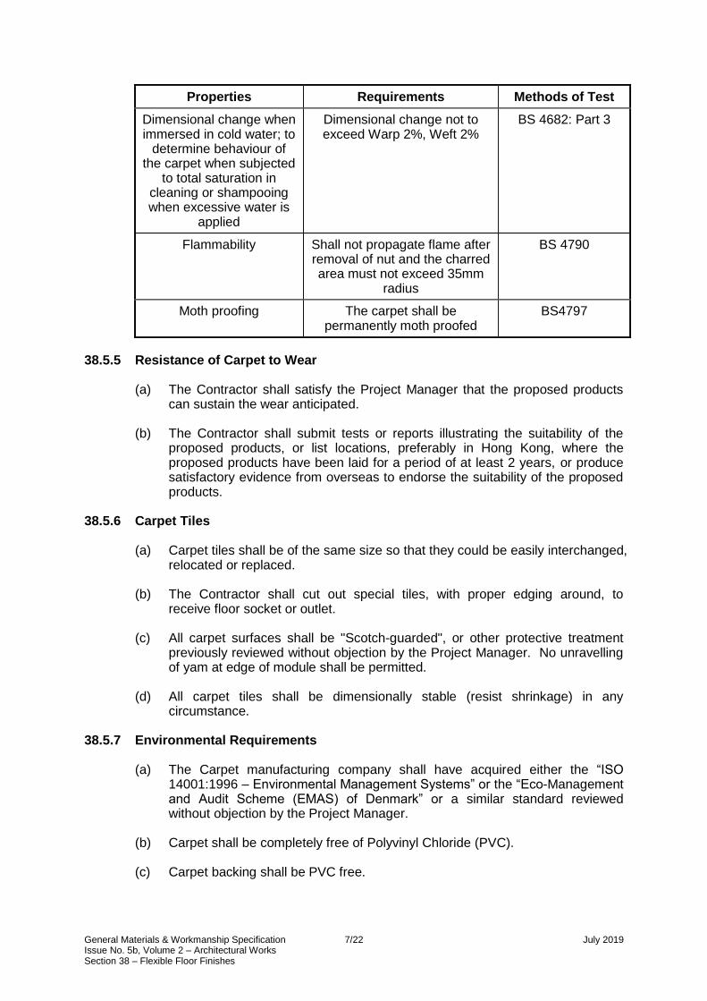
General Materials & Workmanship Specification 7/22 July 2019 Issue No. 5b, Volume 2 – Architectural Works Section 38 – Flexible Floor Finishes
Properties Requirements Methods of Test
Dimensional change when immersed in cold water; to
determine behaviour of the carpet when subjected
to total saturation in cleaning or shampooing when excessive water is
applied
Dimensional change not to exceed Warp 2%, Weft 2%
BS 4682: Part 3
Flammability Shall not propagate flame after removal of nut and the charred area must not exceed 35mm
radius
BS 4790
Moth proofing The carpet shall be permanently moth proofed
BS4797
38.5.5 Resistance of Carpet to Wear
(a) The Contractor shall satisfy the Project Manager that the proposed products can sustain the wear anticipated.
(b) The Contractor shall submit tests or reports illustrating the suitability of the proposed products, or list locations, preferably in Hong Kong, where the proposed products have been laid for a period of at least 2 years, or produce satisfactory evidence from overseas to endorse the suitability of the proposed products.
38.5.6 Carpet Tiles
(a) Carpet tiles shall be of the same size so that they could be easily interchanged, relocated or replaced.
(b) The Contractor shall cut out special tiles, with proper edging around, to
receive floor socket or outlet.
(c) All carpet surfaces shall be "Scotch-guarded", or other protective treatment previously reviewed without objection by the Project Manager. No unravelling of yam at edge of module shall be permitted.
(d) All carpet tiles shall be dimensionally stable (resist shrinkage) in any
circumstance. 38.5.7 Environmental Requirements
(a) The Carpet manufacturing company shall have acquired either the “ISO 14001:1996 – Environmental Management Systems” or the “Eco-Management and Audit Scheme (EMAS) of Denmark” or a similar standard reviewed without objection by the Project Manager.
(b) Carpet shall be completely free of Polyvinyl Chloride (PVC).
(c) Carpet backing shall be PVC free.

General Materials & Workmanship Specification 8/22 July 2019 Issue No. 5b, Volume 2 – Architectural Works Section 38 – Flexible Floor Finishes
(d) Adhesives shall be free of synthetic latex and have no volatile organic compound emissions. Water-based adhesives or adhesive-free installation shall be used.
(e) Metal complex dyes and acid dyes shall not be used for dyeing.
(f) Carpets shall be long lasting, having a service life of not less than 10 years.
(g) Carpets shall not contain harmful substances or have any odour. They shall
pass the testing and labelling program run by the “Carpet and Rug Institute’s Indoor Air Quality Carpet Testing Programme” (USA) or the “Danish Indoor Climate Labelling” (Demark) or “GUT” (European association for environmentally friendly carpets) or similar standard reviewed without objection by the Project Manager.
(h) Carpets shall not contain any harmful substances that prevent them from
being reused, recycled or accepted by a landfill for final disposal. 38.5.8 Carpet Underlays
The Contractor shall provide underlay, which shall be one of the following types in compliance with BS 5808:
(a) felt;
(b) cellular;
(c) rubber crumb; or
(d) composite underlay.
38.5.9 Carpet Grippers
(a) Carpet grippers shall have two rows of small angled pins at not less than 50 mm centres projecting 4 mm from a preformed strip.
(b) The Contractor shall submit samples of carpet grippers for review without
objection by the Project Manager. 38.5.10 Adhesive for Carpet
Adhesive for fixing carpet shall be as recommended by the carpet manufacturers and be compatible with the sub-base. Storage and use shall be in accordance with the manufacturer’s recommendations, e.g. the British Adhesive Manufacturers Association booklet "Safe Handling of Adhesives in Industry".
38.5.11 Carpet Release Bond Agent
Release bond agent shall be reviewed without objection by the Project Manager and comprise either a proprietary release coating or other system. The release coating system shall be used strictly in accordance with the manufacturer's recommendations.

General Materials & Workmanship Specification 9/22 July 2019 Issue No. 5b, Volume 2 – Architectural Works Section 38 – Flexible Floor Finishes
38.5.12 Anti Static Resistance
(a) Where specified, the carpet tiles shall be constructed using anti-static treatments in either or both the pile yarn and backing.
(b) The static control level shall be a maximum of 3.0 kV, measured under the
standard conditions of 23 °C ±1 °C and 25 % ±2 % relative humidity.
(c) The Contractor shall submit proposals for complying with the Specification to the Project Manager for review without objection.
38.5.13 Raised Access Flooring
(a) The raised floor deck shall be installed with fully removable load bearing panels, interchangeable, and supported on adjustable pedestals.
(b) The floor system shall be sturdy, rigid, and firm, constructed from moisture
resistant and rot proof material. The design of the system shall prevent vibration, rattles, rocking squeaks and other noises. Floor panels that are cut shall be supported by additional pedestals and shall have framing modified accordingly.
(c) The Contractor shall provide panel location system to securely locate each
panel and prevent rocking. The system shall not rely on the perimeter wall for lateral stability and shall provide resistance to rolling loads (as AFA Rolling Load Guide Notes Series 1 No.2 1988). The floor system shall remain stable when groups of panels are removed for access or maintenance or any other reason; and
(d) The Contractor shall provide 3 sets of lifting apparatus to facilitate access to
sub-floor for maintenance and alteration. 38.5.14 The aluminium Components for Raised Floor System
The Contractor shall: (a) detail design the extrusions and material thicknesses while maintaining
dimensions shown on the Employer's Drawings;
(b) obtain the total quantity of each material or component from the same supplier or manufacturer unless otherwise agreed with the Project Manager;
(c) fabricate all metal framing members from extruded aluminium in compliance
with BS 1474;
(d) provide aluminium sheeting of minimium 3mm thick with framing a minimium of 1.6mm in compliance with BS 1470; BS EN 485 and BS EN 515;
(e) use the most appropriate grades, strengths, and thicknesses of aluminium to
meet all structural and finishing requirements. The wall thicknesses of aluminium extrusions shall be sufficient for the rigidity in the lengths required in the final installation; and
(f) provide all aluminium fixing brackets and cleats manufactured from the most
appropriate grade of alloy in accordance with BS 1474. They shall be finished to match the metal panels and framing members if visible.

General Materials & Workmanship Specification 10/22 July 2019 Issue No. 5b, Volume 2 – Architectural Works Section 38 – Flexible Floor Finishes
38.5.15 The Support System for Raised Floor System
The Contractor shall: (a) take every precaution to ensure that no chemical or electrolytic action takes
place where dissimilar metals and/or materials are used together. To this end attention is drawn to publication PD 6484 'Commentary on corrosion at bi-metallic contacts and its alleviation'. This is of particular importance where aluminium and aluminium alloys are one of the surfaces. The Contractor shall provide the necessary insulation wherever dissimilar metals occur at interfaces with works that precede the Works;
(b) take every precaution to isolate aluminium components from cementitious
surfaces;
(c) hot-dip galvanise all inaccessible steel in accordance with BS 729;
(d) obtain all alloys of similar finish from an identified source reviewed without objection by the Project Manager and in compliance with the requirements of the relevant British Standard; provide a chemical or other manufacturer’s written specification for the alloy proposed.
38.5.16 Access Floor Accessories
All necessary accessories such as ramps, stairs, railings, air grilles, skirting trims, vertical edging panels, all shall be of a similar standard or quality to the main floor system.
38.5.17 Provision for Service Outlets and Cut Panels
The Contractor shall: (a) provide and install perforated panels (full panel size) for air supply. Location of
the service panels and details of perforation size and pattern are shown on the Employer's Drawings;
(b) provide cut outs for services in the raised floor panels for electrical and other
outlets as located on the Employer's Drawings;
(c) ensure that performance of the panel is in no way impaired due to the integration of such cut outs and panels; and
(d) ensure that any cutting of panels does not affect the water or moisture
resistance of the panels. 38.5.18 Floor Grilles in Computer Rooms
(a) The Contractor shall supply and install perforated raised floor tiles in computer room style raised floors including associated air balancing dampers.
(b) The perforated panels shall be used for supplying air as part of the mechanical
services air conditioning. The performance requirements of the mechanical services shall not be affected by the Contractor's selection of perforated panel.
(c) Perforated panels shall provide a minimum 20 % free area.
(d) Perforated panels shall be easily removable to enable access to air balancing
facilities and shall be suitable for heavy pedestrian traffic.

General Materials & Workmanship Specification 11/22 July 2019 Issue No. 5b, Volume 2 – Architectural Works Section 38 – Flexible Floor Finishes
(e) The maximum pressure drop across a perforated panel at a 2.5 m/s face
velocity shall be 20 Pa.
38.5.19 Floor Panels
All panels shall be of the following dimensional requirements:
(a) removable and fully transferable in position and direction;
(b) closely fit to all perimeters with gap no greater than 15 mm and the edge panels shall be located to prevent movement;
(c) before application of load, the platform floor surface shall be levelled to +/- 1.5
mm over any 5 m2 or +/- 6 mm over the entire floor;
(d) under no load condition, the concavity or convexity of the panel shall not exceed 0.75 mm when measured horizontally parallel to any edge or along the diagonal, and the deviation due to twist shall not exceed 1 mm;
(e) panel deviation from square or work size shall not exceed +/- 0.5 mm;
(f) edge strips if utilised, shall be firmly fixed and shall not peel or become
detached or break. The edging shall resist a pull off strength of 5 N for 5 minutes;
(g) edges of panels shall be chamfered at an angle of 5 degrees for easy removal of panels.
(h) site-cut edges of panels shall be treated to resist fire, moisture, and attack by
vermin etc.;
(i) the dead load of the raised access floor system shall not exceed 1 KN/ m2.
38.5.20 Hydrothermal Requirements of Floor System
(a) The platform floor system, including the pedestals, panels, floor covering and fixings shall withstand the following conditions, without any delamination or other forms of deterioration:
(i) temperature 5 deg. C, relative humidity (RH) 90% on both sides of the
floor panels;
(ii) temperature 5 deg. C and 95% RH in the floor void side of the panels, temperature 25 deg. C and 25% RH on the room side of the panels;
(iii) temperature 8 deg. C and 99% RH in the floor void side of the panels,
temperature 23 deg. C and 55% RH on the room side of the panels;
(iv) temperature 30 deg. C and 30% RH in the floor void side of the panels, temperature 19 deg. C and 60% RH on the room side of the panels; and
(v) temperature variation from 0 deg. C to 60 deg. C with RH 95% on both
sides of the floor panels.
(b) The material shall, under the conditions stated in a), comply with the structural and loading requirements stated in sub-sections 38.4.2 and 38.5.19. The material content of the floor panels shall not be capable of absorbing moisture.

General Materials & Workmanship Specification 12/22 July 2019 Issue No. 5b, Volume 2 – Architectural Works Section 38 – Flexible Floor Finishes
38.5.21 Fire and Safety Requirement of the Raised Floor System
(a) The raised floor system shall be non-combustible.
(b) The raised floor system shall comply with BS 6266 clause 4.4 and BS 5588: Part 3 clauses 11.3.1 and 11.3.2.
(c) The raised floor system shall achieve, within the cavity, Class 1 classifications
when tested in accordance with BS 476: Part 7; an index of Performance (1) not exceeding 12 and a sub index (i) not exceeding 6 when tested in accordance with BS 476: Part 6.
(d) All supporting structure shall be incombustible and shall have a melting point
of not less than 600 oC.
(e) All supporting structure shall have a thermal property such that mean temperature of the upper panel surface shall not increase by more than 140 oC, when subject to the 1 Kg crib fire test.
(f) Materials shall be non-combustible and approved by the Fire Services
Department. It shall be compatible with all other materials used in the raised floor system.
(g) The conductivity for insulation shall not be more than 0.036 w/m deg. C at 24
oC. 38.5.22 Electrical Properties of the Raised Floor System
(a) The system shall have the electrostatic properties such that the resistance between the surface of the floor covering and the main building earth continuity conductor shall be between 5x10⁵ and 2x10 10 ohms at RH 50%.
(b) All metallic components of the floor system shall be capable of being
electrically bonded in compliance with section 38.7.9.
38.5.23 Durability and Other Properties Required of the Raised Floor System
(a) All materials shall be resistant to the growth of fungi, micro-organisms and the attack by insects.
(b) The materials shall be in compliance with BS 1982 method of test for fungal
resistance and manufactured building materials made of or containing materials of organic origin.
(c) The materials used in the system shall not give off any unpleasant odours to
the occupants of the building.
(d) The system supporting components and the floor panels shall have a minimum life of 25 years.

General Materials & Workmanship Specification 13/22 July 2019 Issue No. 5b, Volume 2 – Architectural Works Section 38 – Flexible Floor Finishes
38.6 SUBMISSIONS 38.6.1 Particulars of the Flexible Floor Finishes
The following particulars of the proposed flexible floor finishes shall be submitted to the Project Manager for review without objection:
(a) Contractor’s Drawings showing the fabrication, setting out, joints and details of
all flexible flooring systems;
(b) details of the source, type and properties of all materials;
(c) relevant and current manufacturer’s literature; and
(d) test certificates for carpet to demonstrate that it complies with the requirements of the specification.
38.6.2 Samples
The following samples of proposed materials shall be submitted to the Project Manager together with the particulars referred above: (a) 600 mm x 600 mm samples of each vinyl proposed;
(b) 600 mm x 600 mm samples of each carpet and underlay proposed;
(c) 3 vinyl tiles;
(d) 3 carpet tiles;
(e) 5 sample floor panels;
(f) trims;
(g) thresholds;
(h) nosings; and
(i) 5 no. pedestals
38.6.3 Prototypes
The Contractor shall provide one complete raised access floor assembly comprising 4 panels mounted on the pedestal system (on a substrate the same as the building), and including power points, access systems, etc.

General Materials & Workmanship Specification 14/22 July 2019 Issue No. 5b, Volume 2 – Architectural Works Section 38 – Flexible Floor Finishes
38.6.4 Benchmarks
(a) The Contractor shall, prior to commencement of the raised floor system, construct and establish flexible floor, as detailed below, at location agreed by the Project Manager as benchmarks. Upon receipt of the Project Manager's notice of no objection, the benchmarks shall become the standard to which all subsequent flexible floor system shall conform;
(i) vinyl finish area 3 m x 3 m including joints and edges to other finish;
(ii) carpet floor area 8 m x 8 m including joints and edges to other finish;
and
(iii) raised Floor area with floor finish size 3 m x 3 m.
(b) In the event the Project Manager does not issue a notice of no objection for the proposed benchmarks, the Contractor shall remove and construct a new proposed benchmark before proceeding with any flexible floor works.
38.7 WORKMANSHIP 38.7.1 Tolerances for Raised Access Flooring
(a) Raised access floor pedestals shall be adjustable to provide a finished floor level within ±1.5 mm over 5 m in any direction. Tolerances shall be non-accumulative;
(b) Raised access floor panel levels:
The difference in height between adjacent finished panels shall not exceed 0.5 mm after the application of the specified load and shall not exceed 3.25 mm between the edge of any panel being subjected to any combination of the loadings specified and the nearest edge of any adjacent unloaded panel;
(c) Panel flatness:
(i) the concavity or convexity of any panel under no load conditions shall
not exceed 0.75 mm when measured across a 600 mm module and parallel to any edge or diagonally across the module; and
(ii) the deviation due to twisting under no load conditions of any corner in relation to the other three shall not exceed 1.0 mm over a 600 mm module. This standard shall be maintained when the panel is subjected to the environmental conditions and also after the removal of any concentrated or distributed loads;
(d) Panel Squareness:
The panel deviation from square shall not exceed 0.5 mm on the diagonal length;
(e) Panel Dimensions:
The deviation from the specified size of the panel shall not exceed ±0.5 mm;

General Materials & Workmanship Specification 15/22 July 2019 Issue No. 5b, Volume 2 – Architectural Works Section 38 – Flexible Floor Finishes
38.7.2 Workmanship for Vinyl Tile or Sheet
The Contractor shall: (a) store rolls after delivery, but before laying, in accordance with the
manufacturer’s recommendations. Deformed rolls shall not be used;
(b) not use tiles or sheet which have deteriorated in stock or which have a tendency to curl at the edges and corners;
(c) thoroughly clean the screed or backing from grease, oil, wax, paint, dirt or dust
and fill all cracks, minor holes and services penetration with a filler recommended by the tile or sheeting manufacturer and reviewed without objection by the Project Manager;
(d) lay all tiles, floor and wall sheeting strictly in accordance with the
manufacturer's recommendations. Preheating single tiles shall not be permitted;
(e) apply adhesive in a thin film and spread evenly with a notched or plain trowel
as recommended by the manufacturer. If a notched trowel is used the notches shall be of the size recommended and shall be renewed periodically to ensure the correct spread of adhesive;
(f) closely butt joints and cut accurately at right angles to the tiles or sheet
surface to an agreed design and with only the minimum necessary jointing;
(g) weld joints of PVC sheet to form a continuous surface with PVC welding rods coloured to match the sheeting;
(h) relay any areas insufficiently bonded or showing an uneven surface. The full
width of vinyl sheet, and a minimum length at least equal to twice the width, shall be re-laid. There shall be no patch repairs within the width of a sheet;
(i) after laying thoroughly clean, the tiling or sheeting with water and a detergent
recommended by the manufacturer; apply two coats of non-slip, matt emulsion polish;
(j) protect the floors with covering reviewed without objection by the Project
Manager.

General Materials & Workmanship Specification 16/22 July 2019 Issue No. 5b, Volume 2 – Architectural Works Section 38 – Flexible Floor Finishes
38.7.3 Workmanship for Carpet
(a) The Contractor shall install carpet and underlays in compliance with BS 5325.
(b) The Contractor shall install carpets so that they are flat and of even tension. Carpet shall not be displaced by movement of people or objects on the surface to the point where permanent slackness, rocking or rippling is caused.
(c) The Contractor shall closely fit edges to skirting cover fillets or other
perimeters; joint carpet at doorway within the thickness of the closed door; secure doorway terminations of carpet by sealing, whipping or binding before seaming or covering with cover strips where they abut dissimilar materials.
(d) No carpet jointing shall be permitted at right angles to a door location within 2
m of any door centre line without the express permission of the Project Manager.
(e) No fitting-out of areas with small pieces or off-cuts shall be permitted.
(f) Carpet tiles on raised floor panels shall either be stuck down with double-sided
tape or alternatively with a bonding agent, which shall be integral with the backing of the tile previously reviewed without objection by the Project Manager.
38.7.4 Laying Carpet Underlays
The Contractor shall: (a) provide underlays in all cases except as follows:
(i) where foam or felt backing is an integral part of the carpet proposed;
(ii) where the carpet is to be fully adhered in accordance with the
manufacturer's recommendations;
(iii) where the manufacturer recommends that no underlay is required;
(b) ensure the base is smooth, clean, and dry and compatible with the underlay and carpeting. Adhesive shall be compatible with the base, underlay and carpet;
(c) lightly smooth the underlay by hand to ensure that it lies flat with no bubbles or
wrinkles visible on the surface; secure the underlay sufficiently to preclude movement when the carpet is laid over it.
38.7.5 Seaming and Jointing Carpets
The Contractor shall: (a) plan the layout of the carpet to keep seams to the minimum practicable.
Seams should be unobstructive and positioned such that:
(i) they run the length of the area;
(ii) traffic runs along the length rather than across the seams; and
(iii) seams are not placed in areas subjected to heavier or twisting wear or in doorways or narrow accesses.

General Materials & Workmanship Specification 17/22 July 2019 Issue No. 5b, Volume 2 – Architectural Works Section 38 – Flexible Floor Finishes
(b) seam or joint carpet by one of the following methods:
(i) machine or hand sewing: sew seams to the full length and properly lock off; stitch to an even tension and ensure the seam lies flat after laying; protect the raw edge of the pile where necessary, to prevent loss of pile along the seam;
(ii) reinforced tape and adhesive (cold applied): ensure that the adhesive is
dry before stretching;
(iii) heat bonded tapes: ensure that adequate penetration of adhesive by applying sufficient heat and pressure simultaneously; or
(iv) seaming cement: joint foam backed or unitary-backed carpets with a
continuous bead of seaming cement to the full length of the primary backing and joint under compression.
38.7.6 Installation of Carpets
The Contractor shall secure carpets by using one of the following methods: (a) Carpet gripper method (suitable for woven, tufted, and secondary backed
bonded carpet):
(i) plug and screw or nail carpet gripper strip around the perimeter 6-8mm from the skirting;
(ii) use recommended adhesives between screws and nail centres;
(iii) stretch carpet over the gripper using knee kickers,
(iv) trim the edge of the carpet;
(v) ensure that it is securely trapped in the gap between the gripper and the
skirting; and
(vi) use power stretchers for installations over 7 m long or wide and use a double row of carpet grippers.
(b) Fully adhering method (suitable for all types of carpet):
(i) ensure that the floor is properly dry, free from dust, and contaminants,
which may affect the adhesion;
(ii) spread adhesive evenly and only applied to an area that can be properly bonded and laid at one time;
(iii) obtain maximum adhesive contact by brushing or rolling in accordance
with the manufacturer's recommendations;
(iv) cut edges straight and square before adhesion in accordance with the manufacturer's recommendations;
(v) trim the carpet to the perimeter before the adhesive dries;
(vi) do not permit traffic installation of furniture on adhered areas for at least
24 hours.

General Materials & Workmanship Specification 18/22 July 2019 Issue No. 5b, Volume 2 – Architectural Works Section 38 – Flexible Floor Finishes
(c) Release bonded method (suitable for all types of carpet):
(i) apply the release agent before adhering generally in accordance with the sub-section b) above.
38.7.7 Carpet Protection and Cleaning
The Contractor shall: (a) clear all carpet areas of tools and waste;
(b) remove all pieces of partly loose warp or face yam with napping scissors;
(c) rectify any lumps, surface irregularities and areas of inadequate or uneven
tension that are apparent; and
(d) employ a specialist carpet cleaner to clean the installed carpet immediately prior to handover using a method reviewed without objection by the Project Manager.
38.7.8 Workmanship of the Raised Access Floor
The Contractor shall: (a) before commencement of the work, ensure that the substrate is adequate to
accept the raised floor system and adequate for the fixings to be fully effective; ensure that any mechanical fixings are clear of the reinforcement in the structural slab;
(b) seal and clean the sub-floor before the raised floors installation is commenced;
continue cleaning during installation to prevent entrapment of dirt or rubbish in the floor cavity;
(c) fix the raised floors in accordance with the manufacturer's recommendations
ensuring compliance with design and performance requirements;
(d) set out accurately the raised floors to give level floor free from undulations, steps, ridges, bumps, ripples, and lipping. Rocking panels shall not be accepted. The floor shall not exhibit noise in use, and shall be able to resist all rolling loads without creep and shall feel solid and substantial underfoot;
(e) design and fit bay divisions and movement joints in the raised floors where
necessary fitted to co-ordinate with wall joints and other elements as shown on the drawings;
(f) whenever such alteration is required, agreed the visual criteria with the Project
Manager prior to such alterations being carried out. 38.7.9 Earth Bonding of the Raised Access Floor
The Contractor shall bond to earth all extraneous and exposed conductive parts of the raised access floor system as defined by the latest IEE Regulations and the Code of Practice for the Electricity (Wiring) Regulations of EMSD.

General Materials & Workmanship Specification 19/22 July 2019 Issue No. 5b, Volume 2 – Architectural Works Section 38 – Flexible Floor Finishes
38.8 INSPECTION, TESTING AND COMMISSIONING 38.8.1 Tests of Carpet Tiles Construction
The Contractor shall carry out the following tests on the carpet tiles construction at the rate of one of each test for every one thousand tiles supplied: (a) Fibre content and carpet tiles dimensions shall be tested in accordance with
BS 3655.
(b) Total carpet tiles weight, total pile weight, pile weight above backing, pile height and weft density shall be ascertained in accordance with BS 4233.
(c) Change in surface structure shall be ascertained in accordance with BS 6659.
38.8.2 Tests of Carpet Tiles Performance
The Contractor shall carry out the following tests of carpet tiles performance at the rate of one of each test for every 1,000 tiles supplied:
(a) Insect resistance shall be tested in accordance with BS 4797.
(b) Mildew resistance shall be tested in accordance with BS 6085.
(c) Tuft withdrawal shall be tested in accordance with BS 5229.
(d) Changes in surface texture and colour shall be tested in accordance with BS
6659 (hexapod drum test).
(e) Thickness loss under dynamic loading shall be ascertained in accordance with BS 4052.
(f) Thickness loss under static loading shall be ascertained in accordance with
BS 4939.
(g) Changes in surface structure and colour shall be ascertained in accordance with BS 6659.
(h) Light fastness, shampoo fastness and rubbing fastness shall be tested in
accordance with BS 1006.
(i) Residual oil content shall be ascertained in accordance with BS 3582.
(j) Static electrical propensity and electrical resistance shall be tested in accordance with BS 6654.
(k) The effects of a small source of ignition shall be tested in accordance with BS
4790 (hot metal nut test) and with BS 6307 (methanamine tablet test).
(l) DCM soluble matter shall be determined in accordance with BS 3582.
(m) Abrasion resistance shall be tested in accordance with Wool Industry Research Association Handbook II.
(n) Durability factor and fibre integrity shall be tested in accordance with
International Wool Secretariat TM 283.

General Materials & Workmanship Specification 20/22 July 2019 Issue No. 5b, Volume 2 – Architectural Works Section 38 – Flexible Floor Finishes
(o) NBS flooring radiant panel test shall be carried out in accordance with DIS 9239 and ASTM E 648.
(p) Toxic gas emission shall be tested in accordance with ASTM E 662, F814-83
and F814-84.
(q) Fray resistance shall be tested in accordance with ISO 10833.
(r) The effect of chair castors shall be tested in accordance with ISO DTR 4918; and
(s) The dimensional stability of the carpet tiles shall be tested using the
"Aachener Test" as developed by The Deutsches Teppich - Forschunginstitut
of Aachen, Germany. The permissible maximum change shall be 0.1% from the initial to the final measurement.
38.8.3 Testing for raised floor
(a) Load Tests:
The Contractor shall:
(i) carry out area and point load tests to a minimum of two times the specified load;
(ii) load test single panels representative of the 600 mm x 600 mm panel
size to demonstrate their capability of supporting the specified load areas, partition loads, contained area loads, and point loads;
(iii) carry out load tests utilising a single system panel supported on 750 mm
x 750 mm floor on its support system; place panels on these supports to provide bearing areas equal to an actual installation;
(iv) apply loads through a load application apparatus which simulates the
actual contact areas and land/panel interfacing for that particular type of loading;
(v) apply loads to the panel in increments and deflections of the panel shall
be measured at each load increment;
(vi) load to design load in a minimum of four loading increments, then unload, then reload to design load in four increments, then continue loading in increments to failure or to twice design load (whichever occurs first);
(vii) where a loading type (i.e. a point load through a 200 mm diameter pad)
can be located anywhere on a panel, load test the panel by locating the loading at the most critical location on the panel;
(viii) carry out load testing of single panels, with and without the service holes,
as described above. If the physical make-up of a panel with or without service holes is essentially the same, load tests of panels with the holes present may be used to demonstrate adequacy of the panels without holes;

General Materials & Workmanship Specification 21/22 July 2019 Issue No. 5b, Volume 2 – Architectural Works Section 38 – Flexible Floor Finishes
(ix) test 10% of pedestals on Site with a 3 kg soft body weight rotated through an arc of 90° at a radius of 1m to strike the head of the pedestal. No deformation or failure of fixing shall occur. The test shall not commence until 48 hours have elapsed from the time any adhesive has been used to install the pedestal; and
(x) where the Contractor can demonstrate by structural analysis that one
specified loading condition and/or load location is more severe or more critical than others, use load tests of panels under that more severe or critical condition to demonstrate adequacy of the panel for other loading conditions or locations.
38.9 OPERATIONS AND MAINTENANCE 38.9.1 Operation and Maintenance Manual
The Contractor shall provide an Operation and Maintenance Manual to the Project Manager including, but not limited to, the following: (a) details of the manufacturers of all types of flexible floor finishes;
(b) details relating to the necessary intervals between cleaning cycles and provide
guidance to the Project Manager on vacuuming of primary and secondary trafficked areas. Particular reference should be made to the use of twin motor upright cleaners and their frequency of use;
(c) methods for cosmetic cleaning of stains including guidance on treatments for
water and oil based stains;
(d) wet cleaning and powder cleaning methods and guidance on procedures and the relative advantages and disadvantages of each method considering areas, special machines, cost, time and convenience;
(e) repair and replacement of small areas of the finishes;
(f) protection methods for flexible floor finishes during cleaning of adjacent hard
floor finishes; and
(g) all other maintenance requirements deemed necessary for the proper performance of the flexible floor finishes.

General Materials & Workmanship Specification 22/22 July 2019 Issue No. 5b, Volume 2 – Architectural Works Section 38 – Flexible Floor Finishes
38.9.2 Durability for Raised Floors
(a) The Contractor shall provide primary components which have a predicted service life of not less than 12 years without the need for maintenance, other than regular cleaning. The following components shall be primary components:
(i) all framing and structural support components;
(ii) panels; and
(iii) fixings.
(b) All other components shall have a predicted service life of not less than 8
years.
(c) The Contractor shall state the predicted service life of all components and provide guidance on the required maintenance, replacement periods and methods of replacement.
(d) Secondary components shall be capable of easy replacement without
compromising the structural or visual integrity of the raised floor. Components shall be capable of replacement without progressive dismantling of the raised floor.
38.10 NOT USED

General Material & Workmanship Specification 1/21 July 2019 Issue No. 5b, Volume 2 – Architectural Works Section 39 – Wall Finishes
SECTION 39 WALL FINISHES 39.1 GENERAL
This section provides detailed technical requirements in respect of wall finishes that generally comprise: (a) render;
(b) plaster;
(c) ceramic wall tiling;
(d) stone wall tiling;
(e) resin bonded wall tiling; and
(f) accessories. The materials specified below shall comply with the sections stated, unless otherwise stated in this section: (g) internal cladding systems refer to section 30;
(h) glazing, glazed screens, balustrades and handrails refer to section 32;
(i) linings, sheathings, drywall partitions and toilet cubicles refer to section 33;
(j) architectural metalwork refer to section 35;
(k) hard floor finishes refer to section 37;
(l) flexible floor finishes refer to section 38; and
(m) sanitary fittings refer to section 95.
39.2 NOT USED

General Material & Workmanship Specification 2/21 July 2019 Issue No. 5b, Volume 2 – Architectural Works Section 39 – Wall Finishes
39.3 RELEVANT CODES AND STANDARDS The Standards and Codes of Practice specified in this section are listed below for information only. The Contractor shall comply with the edition of the Standard or Code of Practice listed in the text when stated, or the latest edition when no edition is listed. Where British Standards have been replaced by the new BS EN documents, the old BS number is retained in the text with the new BS EN number listed below.
BS 12 (replaced by BS EN 197-1)
Cement. Composition, specifications and conformity criteria for common cements
BS 146 (replaced by BS EN 197-1)
Cement. Composition, specifications and conformity criteria for common cements
BS 476 Fire tests on building materials and structures
BS 882 (replaced by BS EN 12620+A1)
Specification for aggregates from natural sources for concrete
BS 890 (replaced by BS EN 459-1)
Building lime. Definitions, specifications and conformity criteria
BS 1191 (replaced by BS EN 13279)
Gypsum binders and gypsum plasters
BS 1199 & 1200 (replaced by BS EN 13139)
Aggregates for mortar
BS 1449 (replaced by BS EN ISO 18286 & BS EN ISO 9445-1 & BS EN 10048 & BS EN 10095 & BS EN 10051 & BS EN 10029 & BS EN ISO 9445-2)
Steel plate, sheet and strip. Specification for stainless and heat-resisting steel plate, sheet and strip
BS 3148 (replaced by BS EN 1008)
Methods of test for water for making concrete (including notes on the suitability of the water)
BS 4254 (replaced by BS EN ISO 11600+A1)
Building construction. Jointing products. Classification and requirements for sealants
BS 4551 (replaced by BS 4551+A2 & BS EN 1015)
Mortar. Methods of test for mortar and screed. Chemical analysis and physical testing
BS 4721 (replaced by BS EN 998)
Specification for mortar for masonry
BS 4887 (replaced by BS EN 934-3+A1)
Admixtures for concrete, mortar and grout. Admixtures for masonry mortar. Definitions, requirements, conformity and marking and labelling
BS 5224 (replaced by BS EN 413-1)
Masonry cement. Composition, specifications and conformity criteria
BS 5262 (replaced by BS EN 13914-1)
Design, preparation and application of external rendering and internal plastering. External rendering
BS 5270 Bonding agents for use with gypsum plasters and cement

General Material & Workmanship Specification 3/21 July 2019 Issue No. 5b, Volume 2 – Architectural Works Section 39 – Wall Finishes
BS 5492 (replaced by BS EN 13914-2 & BS 8481)
Design, preparation and application of external rendering and internal plastering. Internal plastering & Design, preparation and application of internal gypsum, cement, cement and lime plastering systems
BS 5385 Wall and floor tiling
BS 6431 (replaced by BS EN 14411)
Ceramic tiles. Definition, classification, characteristics, assessment and verification of constancy of performance and marking
BS 6452 Part 1 (replaced by BS EN 13658)
Metal lath and beads
BS 8000 Part 10 Workmanship on building sites. Code of practice for plastering and rendering
BS 8204 Screeds, bases and in situ floorings
39.4 DESIGN AND PERFORMANCE CRITERIA 39.4.1 Contractor’s Responsibilities
The Contractor shall: (a) Install the wall finishes based upon the Employer's Drawings and the
requirements of the Specification.
(b) For all wall tiling:
(i) design the fixing method for wall tiles including any bedding, render, adhesive or mechanical fixings;
(ii) submit the design and Contractor’s Drawings, showing sufficient details
for installation, for review without objection by the Project Manager;
(iii) provide and install tiles using the method as recommended by the tile manufacturer, including the preparation of the wall substrate, laying, joint grouting, protection and cleaning before applying for a Completion Certificate;
(iv) adopt the design/visual criteria shown on the Employer’s Drawings;
(v) unless shown otherwise, align wall tile joints with floor tile joints and
prevent dimensional creep; and
(vi) set out floor and wall tiles from the setting out points where shown on the Employer’s Drawings.

General Material & Workmanship Specification 4/21 July 2019 Issue No. 5b, Volume 2 – Architectural Works Section 39 – Wall Finishes
39.5 MATERIALS 39.5.1 Rendering
(a) Ordinary Portland cement shall comply with BS 12.
(b) Water shall comply with section 20 (Concrete) and tested in accordance with BS 3148.
(c) Sand for mixes not incorporating lime shall be from either clean hard durable
crushed rock or clean sand free from salt and shall conform to the grading limits set out below;
Table 39.1: Grading of Sand for Renders
B.S. Sieve Percentage by weight passing B.S. Sieve
5.00 mm 100
2.36 m 90 – 100
1.18 mm 70 – 100
0.60 mm 40 – 80
0.30 mm 5 – 40
0.15 mm 0 – 10
(d) Sand for mixes incorporating lime shall be clean natural sand free from salt to
conform to the grading limits set out below; Table 39.2: Grading of Sand for Render Mixes with Lime
B.S. Sieve Percentage by weight passing B.S. Sieve
2.36 mm 100
1.18 mm 90 – 100
0.60 mm 55 – 100
0.30 mm 5 – 50
0.15 mm 0 – 10
(e) Lime shall comply with BS 890 and section 26 (Masonry and Blockwork).
(f) Admixtures and additives shall comply with BS 4887 and section 26 (Masonry
and Blockwork).
(g) Bonding agents shall be compatible with the substrate and finish and shall be proprietary products previously reviewed without objection by the Project Manager. They shall be used strictly in accordance with the manufacturer’s recommendations and shall be supplied in containers clearly marked in the factory with the expiry date. Expired material shall not be used.

General Material & Workmanship Specification 5/21 July 2019 Issue No. 5b, Volume 2 – Architectural Works Section 39 – Wall Finishes
39.5.2 Plastering
(a) Steel lathing, shall comply with BS 1369: Part 1 from a manufacturer previously reviewed without objection by the Project Manager, and shall be either:
(i) plain expanded type of 6mm short way mesh coated with tight coat
galvanizing and weighing not less than 1.6 kg/m2; or
(ii) ribbed expanded type similarly coated and weighing not less than 2.25 kg/m2.
(b) Galvanized steel corner beads, plaster stops and movement joint beads shall
have expanded metal wings and the details reviewed without objection by the Project Manager.
(c) Wire netting shall comply with BS 1485, of 0.9 mm galvanized wire and 50 mm
mesh.
(d) Staples shall be galvanized steel wire staples.
(e) Tying wire shall be 1.25 mm annealed steel wire, galvanized in compliance with BS 433.
(f) Gypsum plaster shall be retarded hemihydrates gypsum plaster in compliance
with BS 1191: Part 1, Class B of the following types:
(i) Undercoat Plaster
Type a – 1 Browning plaster 2 Metal lathing plaster
(ii) Final Coat Plaster
Type b – 1 Finish plaster 2 Board finish plaster
(g) Gypsum plaster shall be delivered to Site in sealed containers and stored in weather tight structures with a raised floor. The Contractor shall store different types of consignments separately and use in the order of their delivery.
(h) Plasterboard shall comply with BS 1230: Part 1 “gypsum lath" or "gypsum
baseboard".
(i) Nails for "lath" or "baseboard" shall be 30 x 2.6 mm plasterboard galvanized steel nails, jagged shank type in compliance with BS 1202: Part 1:
(i) 30 x 2.65 mm for plasterboard not exceeding 12.7 mm thick; and
(ii) 40 x 2.65 mm for plasterboard 19 mm thick.
(j) Reinforcement for joints in plasterboard shall be jute scrim cloth not less than
90 mm wide.

General Material & Workmanship Specification 6/21 July 2019 Issue No. 5b, Volume 2 – Architectural Works Section 39 – Wall Finishes
39.5.3 Premixed plaster
(a) Premixed plaster shall be factory produced by weighted combination of plaster raw materials and chemicals and supplied to Site in bags. Mixing with clean water shall be required before application.
(b) Premixed plaster shall be either cement based or gypsum based.
(c) Cement based plaster shall contain mineral filler material as aggregate and
Portland cement as main binder, with additives for improved compressive strength and reduced shrinkage.
(d) Gypsum based plaster shall be used in internal weather protected areas only,
and shall contain pre-mixed minerals, gypsum based rendering materials and additives which could be applied in one single thick application without cracking and separation from the substrate.
(e) The premixed plaster shall comply with BS 5262, BS 5492 and BS 1191. The
premixed plaster manufacturing company shall have acquired ISO certification in their manufacturing process of the premixed plaster product.
39.5.4 Specialist and Proprietary Plaster / Renders
(a) Acoustic plaster shall be a proprietary plaster, previously reviewed without objection by the Project Manager, free from asbestos, mixed and applied in accordance with the manufacturer's recommendations.
(b) Stone chippings for exposed aggregate rendering or Shanghai plaster shall be
granite, white stone or marble chippings, graded from 3 to 5 mm, and free from dust.
(c) Resin, epoxy, urethane and acrylic based decorative finishes shall be
proprietary products applied by specialist contractors previously reviewed without objection by the Project Manager.
39.5.5 Ceramic Wall Tiling
Glazed ceramic wall tiles shall comply with BS 6431, Group A IIa or B IIa with water absorption not exceeding 6% and to the sizes stated on the Employer’s Drawings. Tiles shall be glazed, white or coloured as required with flat cushion edge or inclusive spacer lugs as required.
39.5.6 Resin Bonded Wall Tiling
Tiles shall be from a manufacturer previously reviewed without objection by the Project Manager and comply with the standards as specified in the Specification. The tiles shall have 1 mm x1 mm chamfer along all exposed edges unless otherwise specified. The Contractor shall submit samples for review without objection by the Project Manager.
39.5.7 Stone Wall Tiling
(a) Stone (granite) wall tiles shall be produced by a manufacturer reviewed without objection by the Project Manager.
(b) The surface of the tiles shall be cut and pre-finished at the point of
manufacture prior to delivery.

General Material & Workmanship Specification 7/21 July 2019 Issue No. 5b, Volume 2 – Architectural Works Section 39 – Wall Finishes
(c) The Contractor shall ensure that the wall tiles conform or are similar in size, thickness, texture and colour to the tiles in adjacent areas and that the same type of stone is supplied by the same quarry in quality assured batches. The Contractor shall ascertain and satisfy the Project Manager that the elected supply source shall achieve the quality and quantity of tiling in areas to match with existing.
(d) Following the cutting of the tiles along a certain grain, this grain direction shall
be maintained when the stone is laid. 39.5.8 Mosaic Tiles
Unless otherwise specified, mosaic tiles shall be from a manufacturer previously reviewed without objection by the Project Manager and as follows: (a) glass mosaic tiles shall be fully vitrified glass tile size 20x20 mm and 4 mm
thick, regular in shape, free from cracks or sharp edges and uniform in colour and texture;
(b) glazed ceramic mosaic tiles shall be similar to glazed wall tiles but size 18x18
mm or 25x25 mm and 5 mm thick and with square edges; and
(c) unglazed vitreous mosaic tiles shall be size 18x18 mm or 18 x38 mm or 38x38 mm and 4 or 5 mm thick with matching coved tiles and from the colour range specified.
39.5.9 Adhesives
Adhesive for tiles or mosaics shall be a proprietary brand that has been reviewed without objection by the Project Manager.
39.5.10 External Render System for Concrete
(a) The external render system for concrete shall be a water-based outdoor paint with a base of acrylic-siloxanic resins in aqueous dispersion and filler aggregates, to protect outdoor wall surfaces over an acrylic-siloxanic water-based highly washable outdoor filler paint with anti-mold anti-algae qualities. It shall be applied directly to concrete or masonry.
(b) The external render system for concrete shall be suitable for a marine environment and an airport environment with proximity to runway and aircraft.
(c) Colours / Texture
(i) Custom colour to match material schedule and to the satisfaction of the Project Manager
(ii) Custom texture to match material schedule and to the satisfaction of the Project Manager

General Material & Workmanship Specification 8/21 July 2019 Issue No. 5b, Volume 2 – Architectural Works Section 39 – Wall Finishes
39.6 SUBMISSIONS 39.6.1 Particulars of Wall Finishes
The following particulars of the proposed wall finishes shall be submitted to the Project Manager for review without objection prior to the installation of finishes: (a) Contractor’s Drawings which shall illustrate setting out, interfaces, internal and
external corners and skirting details;
(b) details of the source, type and properties of materials; and
(c) current technical literature. 39.6.2 Samples
(a) The Contractor shall submit the following samples of proposed materials to the Project Manager, together with the particulars referred above, for review without objection:
(i) 3 samples of each type of tile;
(ii) 3 additional samples of the extreme lightest colour of each type of resin
bonded tile and stone tile;
(iii) 3 additional samples the extreme darkest colour of each type of resin bonded tile and stone tile;
(iv) samples of stone tile anchors;
(v) samples of all grouts, mastics and sealants; and
(vi) representative samples of typical control joints.
(b) The Contractor shall submit sample panels of 3 m x 3 m for all wall, tile or slab
finishes including joints, edge details, pointing etc. and obtain a notice of no objection from the Project Manager.
39.6.3 Benchmarks
(a) The Contractor shall, following receipt of no objection from the Project Manager of relevant samples and prior to commencement of wall finish works, construct and establish benchmarks as part of the wall finish works at locations to be determined by the Project Manager.
(b) The benchmark area shall include each wall finish material, incorporating at
least one external corner and one internal corner. The extent of the each area shall be minimum 3 m wide and 3 m high from floor, skirting to ceiling.
(c) After the Project Manager has reviewed these areas with no objection, the
benchmark shall become the standard to which all subsequent wall finish works shall conform.
(d) In the event the Project Manager does not issue a notice of no objection for a
proposed benchmark, the Contractor shall remove and construct a new proposed benchmark before proceeding with any wall finish works.

General Material & Workmanship Specification 9/21 July 2019 Issue No. 5b, Volume 2 – Architectural Works Section 39 – Wall Finishes
39.7 WORKMANSHIP 39.7.1 Tolerances
Finished surfaces shall have no sudden irregularities. The tolerances for ceramic wall tiles shall be in accordance with BS 6431.
39.7.2 Rendering Workmanship
The Contractor shall: (a) mix mortar or plaster in compliance with section 26 (Masonry and Blockwork);
(b) protect existing work with boards, dust sheets, and the like. Droppings on
finished work shall be cleaned off immediately;
(c) keep plant and tools clear and free of traces from previous mixes;
(d) not use mechanical coating methods of application without permission of the Project Manager;
(e) hack off extraneous concrete projections and fins;
(f) remove efflorescence, laitance, oil, grease, all traces of release agents, dirt,
and loose material by dry brushing or scraping;
(g) protect surfaces from weather and ensure that they are completely compatible with the finish to be applied before commencement of work;
(h) at junctions between dissimilar solid backgrounds in the same plane which are
to receive the same applied finish, fix a strip of steel galvanized lathing extending 150 mm (minimum) in width each side of the junction, nailed with 40mm nails or stapled to plugs at 100 mm centres on both edges;
(i) clean all laitance, dust, oil or any other such substances from the concrete
surface;
(j) mix splatterdash to consist of (1:2) cement : coarse sand or granite fines with a bonding agent such as a styrene-butadiene rubber (SBR) latex, an ethyl vinyl acetate (EVA) emulsion or an acrylic emulsion previously reviewed without objection by the Project Manager;
(k) apply splatterdash to concrete vertical surfaces and soffits immediately after
striking formwork. The mixture shall be applied by dashing it on the wall to give a complete coverage with a rough texture not exceeding 5 mm thickness. The surface shall be maintained moist for 24 hours;
(l) allow splatterdash to cure and harden for at least two days before applying
rendering/bedding screed;

General Material & Workmanship Specification 10/21 July 2019 Issue No. 5b, Volume 2 – Architectural Works Section 39 – Wall Finishes
(m) Where finish or screed is to be bonded to hardened or existing concrete wall or base:
(i) thoroughly hack concrete to remove laitance and expose coarse
aggregate shortly before applying finish or screed;
(ii) thoroughly clean and wet surface 24 hours before applying finish or screed and remove surplus water; and
(iii) brush neat cement slurry into damp surface immediately before applying
finish or screed, or
(n) apply proprietary bonding agent previously reviewed without objection by the Project Manager in accordance with the manufacturer's recommendations;
(o) construct movement joints at maximum 4m centres in each direction equally
spaced or as shown on the Employer’s Drawings or as directed by the Project Manager to comply with dimensioned requirements.
39.7.3 Rendering Finishing
(a) Surface finishes shall be either:
(i) smooth finish: - finish with a steel trowel or power float to a smooth surface, free from blemishes;
(ii) wood float finish: - finish with a dry wood float to give an even overall
surface;
(iii) textured finish: - finish by stippling, scraping or other means to produce a textured surface reviewed without objection by the Project Manager;
(iv) rough cast finish: - throw onto the undercoat a wet mix of aggregate and
cementitious material; or
(v) machine applied textured finish: apply in accordance with the manufacturer's recommendations.
(b) Wall and ceiling finishes shall be smooth, flat and to correct line and level.
Maximum deviation permitted in surfaces shall be 3 mm from a 1,800 mm straight edge. Angles and corners shall be right angles, unless otherwise required, with walls and reveals plumb and square.
(c) The Contractor shall prevent excessively rapid or localized drying out of wall
and ceiling finishes by a means previously reviewed without objection by the Project Manager.
(d) Immediately after laying, the Contractor shall protect surface of renders or in-
situ finishes from wind, sunlight, wear, discolouration or other damages until completion.

General Material & Workmanship Specification 11/21 July 2019 Issue No. 5b, Volume 2 – Architectural Works Section 39 – Wall Finishes
39.7.4 Plasterboard workmanship The Contractor shall: (a) carry plasterboard on edge, and stack plasterboard flat on level surface,
properly supported to prevent sagging or bending. Plasterboard shall be stacked off the ground inside a building;
(b) keep plasterboard dry, prevent mould growth, and programme deliveries to
minimize storage periods on Site during periods of high humidity;
(c) fix plasterboard with fixing in compliance with BS 8212;
(d) fix plasterboard to wood bearers as follows:
(i) nail boards at each support at 150 mm centres, setting out from the centres of the board and 15 mm (minimum) from edges; and
(ii) provide gap of 3 to 5 mm between edges;
(e) treat joints, etc. in plasterboard as follows:
(i) fill all joints, nail holes and other imperfections with board finish plaster;
and (ii) press strips of joint reinforcement into the plaster, trowel flat and allow
the plaster to set, but not dry out before commencement of general plastering.
39.7.5 Plastering Workmanship
The Contractor shall: (a) use plastering and rendering in compliance with BS 5492 and BS 5262;
(b) dub out if necessary to correct any inaccuracies, in layers 10 mm (maximum)
thick in same mix as the first coat;
(c) allow drying out before the next coat is applied. Total thickness of dubbing out shall not exceed 25 mm;
(d) cross scratch each coat to provide key;
(e) fix steel lathing as follows:
(i) fix taut with the largest dimension of mesh running perpendicular to
direction of supports;
(ii) apply one coat of bituminous paint to cut ends;
(iii) fix at 100 mm centres to wood with staples, to brickwork or concrete in accordance with section 39.7.2.h) and to steelwork with tying wire at 75 mm centres; and
(iv) lap 25 mm (minimum) generally, and 50 mm where end laps occur
between supports. Secure laps with tying wire at 75 mm centres;
(f) allow 3 days for undercoats to dry out thoroughly before applying next coat, and cross scratch undercoats to provide key for next coat;

General Material & Workmanship Specification 12/21 July 2019 Issue No. 5b, Volume 2 – Architectural Works Section 39 – Wall Finishes
(g) apply cement rendering consisting of cement and sand or granite fines 1:3 with surface finish required as follows:
(i) rendering not exceeding 10mm thick in one coat; and
(ii) rendering exceeding 10mm thick in two coats, with finishing coat 5 mm
thick;
(h) apply external rendering to splatterdashed surfaces consisting of cement, lime and sand in two coats as follows:
(i) undercoat 10 mm(minimum) thick-mix l:3;
(ii) finishing coat 10 mm (maximum) thick - mix 1:3, with textured finish;
(iii) total thickness of splatterdash & external rendering shall not exceed 20
mm;
(iv) undercoat shall be thoroughly dry before application of the finishing coat; and
(v) Pulverized Fly Ash (PFA) shall not be used for the external rendering
/plastering;
(i) apply internal lime plaster consisting of cement, lime and sand in two coats on solid backgrounds as follows:
(i) undercoat shall be 1:3 cement : sand mix
(ii) finish coat shall be lime plaster gauged (cement : lime : sand 1:2:6) with
not more than 25 % by volume of lime putty. Addition of paper-pulp is not allowed;
(iii) thickness of undercoat shall not exceed 10 mm to walls and 5 mm to
soffits;
(iv) thickness of finishing coat to walls and soffits shall be at least 3 mm;
(v) the drying out time for undercoats before the application of finishing coats shall comply with sub-section 39.7.5. (f);
(vi) metal plaster corner beads and stops shall be provided where specified
and in accordance with n) below;
(vii) total thickness of plaster not exceed 15 mm to walls and 10 mm to soffits;
(viii) Pulverized Fly Ash (PFA) shall not be used for the internal plastering.
(j) apply gypsum plaster generally in two coats as follows:
(i) first coat consisting of Browning plaster and sand 1:2 or cement and sand 1:3;
(ii) finishing coat of neat finish plaster, or finish plaster with up to 25% of
lime putty added, with smooth finish 5 mm maximum;
(iii) total thickness of plaster shall not exceed 15 mm;

General Material & Workmanship Specification 13/21 July 2019 Issue No. 5b, Volume 2 – Architectural Works Section 39 – Wall Finishes
(iv) proprietary gypsum plaster previously reviewed without objection by the Project Manager shall be used in strict accordance with the manufacturer’s technical specifications and recommendations.
(v) where specified, bonding agents for use with gypsum plaster shall
comply with BS 5270: Part 1;
(k) apply gypsum plaster in three coats on steel lathing as follows:
(i) first coat consisting of metal lathing plaster and sand 1:1.5;
(ii) second and finishing coats – same as two-coat system above; and
(iii) total thickness of plaster shall not exceed 13 mm measured from the outer face of the lathing;
(l) apply gypsum plaster as one finishing coat 5 mm (maximum) thick on
plasterboard towelled to a smooth surface using as minimum water as possible;
(m) construct arises square or pencil rounded as required;
(n) use metal beads for internal plastering and dry lining in compliance with BS
6452: Part 1;
(o) provide and fix metal corner beads, plaster stops and movement joints when specified, including nailing, stapling or fixing with plaster dabs and trowel the finishing coat flush with the bead;
(p) provide metal lathing to bridge across mullions where expansion or movement is not required, including nailing, fixing or stapling the lathing to the walls adjacent to the mullions and to the mullion;
(q) mix and apply acoustic plaster by special spray equipment in accordance with
the manufacturer's recommendations to the thickness and number of coats specified.

General Material & Workmanship Specification 14/21 July 2019 Issue No. 5b, Volume 2 – Architectural Works Section 39 – Wall Finishes
39.7.6 Shanghai Plaster
The Contractor shall apply exposed aggregate rendering or "Shanghai" plaster in two coats as follows:
(a) first coat 10 mm thick, consisting of cement and sand 1:3;
(b) finishing coat 10 mm thick, consisting of cement and stone chippings 1:1, with
the chippings mixed in one of the proportions shown in the table 39.3 below. Before the finishing coat has set, scrub off the surface to expose the aggregate.
Table 39.3: Shanghai Plaster Chipping Mixes
Colour
Cement
Stone Chippings
Dark Grey/ Light Grey/White
Marble Chippings Black/White
Dark Medium White
Ordinary White White
70%
60%
-
-
20%
-
20%
20%
-
10%
-
-
-
20%
100%
General Material & Workmanship Specification 15/21 July 2019 Issue No. 5b, Volume 2 – Architectural Works Section 39 – Wall Finishes
39.7.7 Premixed plaster
The Contractor shall: (a) mix premixed plaster and clean water on Site with portable electrical mixer or
other equipment according to manufacturer’s recommendations; use accurate amount of water to ensure effective mixing and consistent quality;
(b) store bagged premix mortar separately by types, off the ground in dry, well-
ventilated and covered space; use material within manufacturer recommended time limit;
(c) prepare substrate with tolerance of evenness +5 mm for internal concrete wall,
block wall and beams and +3 mm for internal ceiling soffit;
(d) prepare substrate to be clean, free from dust, contamination, paint, oil and loose scale; dampen dry substrate before plastering;
(e) treat substrate with splatterdash or key substrate before application if required
by manufacturer’s recommendations;
(f) not use mixes after initial set has taken place and not re-temper or reconstitute mixes unless permitted by the manufacturer’s instructions;
(g) use experienced applicator to carry out the premixed plaster work. Employ
workers and supervisory staff fully instructed and trained on the method of preparation and application in accordance with the manufacturer’s recommendations;
(h) apply cement based premixed plaster with trowel or spraying machine in
several coats. Application methods, thickness, number of coats and drying time between coats shall be strictly in accordance with manufacturer’s recommendations;
(i) apply gypsum based premixed plaster with trowel or spraying machine in
single coat of thickness in accordance with manufacturer’s recommendations;
(j) level half-set plaster with featheredge; scrape off surplus material and work from bottom to top of wall;
(k) allow drying time of 30-60 minutes in accordance with manufacturer’s
recommendations; sprinkle surface with clean water and smooth with hard sponge float to remove trowel and featheredge marks in circular motion.

General Material & Workmanship Specification 16/21 July 2019 Issue No. 5b, Volume 2 – Architectural Works Section 39 – Wall Finishes
39.7.8 Preparation for Tiling The Contractor shall: (a) scrub the rendered masonry wall with water containing detergent to remove
completely all mould, oil, surface retarder and other materials incompatible with the bedding; rinse with clean water and allow to dry unless specified otherwise;
(b) survey the specified area for tiling when necessary to obtain a setting out point
for the tiles;
(c) set out all ceramic tiled wall and floor tiles on a grid reflecting the tile module and both surfaces shall be co-ordinated onto this grid, except where indicated on the Employer's Drawings;
(d) make joints true to line, continuous and without steps;
(e) make joints in walls that are parallel to the main axes of the space or specified
features;
(f) keep cut tiles to a minimum; cut tiles shall be as large as possible and placed in unobtrusive locations;
(g) where positions of movement joints are not specified, agree their position with
the Project Manager;
(h) take particular care in setting out the finished tiled wall surface alignment to achieve the dimensional requirements in accordance with the Employer’s Drawings prior to the construction of the background; and
(i) set out all critical tiling lines in situ before commencement of tiling works. The
setting out lines shall demonstrate the Contractor’s understanding of the design intent for achieving tiling accuracy throughout the floor and walls. The setting out line shall be reviewed without objection by the Project Manager.

General Material & Workmanship Specification 17/21 July 2019 Issue No. 5b, Volume 2 – Architectural Works Section 39 – Wall Finishes
39.7.9 Fixing Ceramic Wall Tiles
Wall tiling shall comply with BS 5385: Part 1 for internal wall tiling and BS 5385: Part 2 for external wall tiling. Tiles shall be fixed to render as follows: (a) Thick bed method:
The Contractor shall:
(i) soak tiles, mixed from six boxes, in clean water for 30 minutes (minimum); stack to drain and fix as soon as the surface water has drained off;
(ii) damp the wall screed with clean water sufficiently to prevent it absorbing
water from the bedding mortar;
(iii) butter the back of each tile with cement and sand (1:3) or granite fines (1:3) and tap firmly into position so that the bed is solid throughout. Thickness of finished bed shall be 5 to 15 mm;
(iv) make joints minimum 2 mm wide and maximum 3.5 mm wide unless
specified otherwise, and maintain one joint width for each type of tile;
(v) make any adjustment to tiles within 10 minutes of fixing;
(vi) clean tiles and joints before bedding hardens;
(vii) grout up joints 24 hours (minimum) after fixing tiles; clean off surplus grout as work proceeds; and
(viii) clean tiles prior to applying for a Completion Certificate.
(b) Thin bed method:
The Contractor shall:
(i) fix wall tiles, mixed from six boxes, using a bed of adhesive in accordance with the manufacturer's recommendations; and
(ii) grout up joints using a proprietary grout as specified.

General Material & Workmanship Specification 18/21 July 2019 Issue No. 5b, Volume 2 – Architectural Works Section 39 – Wall Finishes
39.7.10 Fixing External Tiles to Concrete Splatterdashed Surfaces
(a) Thick bed method:
The Contractor shall:
(i) apply wall screed of (1:3) cement: sand to maximum thickness of 10 mm. Allow the wall screed to dry off thoroughly;
(ii) soak tiles in clean water for 30 minutes, stack to drain and fix as soon as
the surface water has drained off;
(iii) apply mortar slurry of (1:3) cement and sand with water/cement ratio of 0.5 by weight to thickness of 10mm on the wall screed;
(iv) pre-fill the bedding surface of the tiles with mortar slurry before fixing to the wall screed;
(v) affix the tile by trowel knock procedures; knock the centre of tile using
the handle of a trowel first and knock all the edges of a tile till the mortar slurry flows out from the tile edges;
(vi) make joints minimum 2 mm wide and maximum 3.5 mm wide unless
specified otherwise, and maintain one joint width for each type of tile;
(vii) make any adjustment to tiles within 10 minutes of fixing;
(viii) clean tiles and joints before the slurry hardens;
(ix) grout tiles minimum 24 hours after fixing tiles; clean off surplus grout as work proceeds; and
(x) clean tiles prior to applying for a Completion Certificate.
(b) Thin bed method:
The Contractor shall:
(i) apply wall screed of cement and sand 1:3 to maximum thickness of 10 mm; allow the wall screed to dry off thoroughly;
(ii) fix wall tiles to the wall screed using an adhesive reviewed without
objection by the Project Manager in accordance with the manufacturer’s recommendations; and
(iii) grout joints using an grout reviewed without objection by the Project
Manager.

General Material & Workmanship Specification 19/21 July 2019 Issue No. 5b, Volume 2 – Architectural Works Section 39 – Wall Finishes
39.7.11 Fixing Mosaic Tiles
(a) Thick bed method direct to concrete base:
The Contractor shall:
(i) lay semi-dry mix cement and sand 1:4 bed thoroughly compacted to the required thickness (20 mm minimum) finished to the required levels and falls;
(ii) pour cement and sand slurry over the bedding and spread and trowel 3
mm thick;
(iii) coat back of sheets of mosaic tiles with cement slurry immediately before fixing. Slurry shall be same colour as the final grout;
(iv) fix sheets of mosaic tiles and tamp firmly into bed, maintaining straight
and regular joints; make joints between sheets equal to tile joints; and
(v) remove backing paper, complete final straightening and rub surface coloured grout as specified; fill joints and clean surplus grout from face of tiles as work proceeds.
(b) Thick bed method to wall render:
The Contractor shall:
(i) damp the wall screed with clean water sufficiently to prevent it absorbing
water from the bedding mortar;
(ii) apply bedding coat of mortar 10 mm (maximum) thick consisting of cement and granite fines 1:3;
(iii) coat surface of wall screed and back of sheets of mosaic tiles with slurry
immediately before fixing. Slurry shall be of same colour as the final grout;
(iv) fix sheets of mosaic tiles and tamp firmly into position maintaining
straight and regular joint, make joints between sheets equal to joints between tiles; and
(v) remove backing paper, complete final straightening and rub surface with
grout from face of tiles as work proceeds.
(c) Thin bed method:
The Contractor shall:
(i) fix mosaic tiles using a bed of adhesive reviewed without objection by the Project Manager and in accordance with the manufacturer's recommendations;
(ii) grout up joints using a proprietary grout with colour as specified or
reviewed without objection by the Project Manager.

General Material & Workmanship Specification 20/21 July 2019 Issue No. 5b, Volume 2 – Architectural Works Section 39 – Wall Finishes
39.7.12 Stone Wall Tiles
The Contractor shall: (a) fix stone wall tiles in accordance with section 29 (Curtain Walling) for heights
greater than 1.2 metre above any structural floor level;
(b) fix stone using grade 316 stainless steel for all brackets and shims;
(c) use proprietary anchor bolts and studs, reviewed without objection by the Project Manager, for all connections to the substrate;
(d) select bolts and all other materials to avoid bi-metallic corrosion, providing insulating washers and bushes where necessary; and
(e) install fixings into granite with an epoxy adhesive, reviewed without objection
by the Project Manager.
39.8 INSPECTION, TESTING AND COMMISSIONING 39.8.1 Hammer Test
The Contractor shall: (a) test the adhesion between the wall finish and the substrate by tapping the
surface with a hammer for all rendered and tiled areas, including edges and corners of bays; and
(b) where a hollow sound indicates poor adhesion, carefully cut out the defective
area, taking care to avoid damage to the substrate, and relay the area. Test the re-laid area again for adhesion.
39.8.2 Infrared Test
The Contractor shall: (a) carry out infrared thermographic scanning by a specialist previously reviewed
without objection by the Project Manager for all external render and tiled areas after installation; and
(b) submit test report within 4 months upon completion of external tiling.

General Material & Workmanship Specification 21/21 July 2019 Issue No. 5b, Volume 2 – Architectural Works Section 39 – Wall Finishes
39.8.3 Testing Stone and Resin Bond Tiles The Contractor shall: (a) confirm that the source of each stone and resin bond wall tile selected can
provide the quantity and consistent quality of material at the required rates of production.
(b) confirm that source of each stone and resin bond tile complies with the
following technical criteria of the American Society for Testing and Materials (ASTM):
C97 Density of material > 2,560 kg/m³ C97 Co-efficient of water absorption < 0.4% C99 Modulus of rupture> 10.34 MPa C170 Compressive strength > 131 MPa C880 Flexural strength > 131 MPa;
(c) provide evidence of the quarrying and manufacturing capability including:
(i) quarry /manufacturing process;
(ii) availability of stone;
(iii) output of quarry;
(iv) output of processing plant;
(v) batching and numbering;
(vi) methods of storage;
(vii) future availability of stone; and
(viii) previous experience.
39.8.4 Fire Rating
The Contractor shall use wall tiles with the surface spread of flame Class 1 in accordance with BS 476: Parts 6 and 7.
39.9 OPERATIONS AND MAINTENANCE 39.9.1 Operation and Maintenance Manual
The Contractor shall provide an Operation and Maintenance Manual for wall finishes including, but not limited to, particulars of material manufacturers, quarry source of stone, material finishes, wall finish composition, movement joints, expansion joints, adhesives, sealers, grouts and cleaning requirements.

[this page not used]

General Materials & Workmanship Specification 1/18 July 2019 Issue No. 5b, Volume 2 – Architectural Works Section 40 – Painting and Decoration
SECTION 40 PAINTING AND DECORATION
40.1 GENERAL
This section provides detailed technical requirements in respect of painting and decoration which generally comprise: (a) emulsion paint on plaster board /plaster; (b) emulsion paint on render; (c) masonry paint; (d) textured acrylic paint; (e) dust proof sealer to screed floors; (f) epoxy paint to steelwork; (g) micaceous Iron Oxide paint; (h) Polyester Powder Coatings (i) aluminium primer; (j) zinc chromate primer; (k) bituminous paint; (l) knotting; (m) stopping; (n) rust inhibitor; (o) sealers; (p) wood preservative; (q) polyurethane paint; (r) gloss paint; and (s) road marking paint. The materials specified below shall comply with the sections stated, unless otherwise stated in this section: (t) structural steelwork refer to section 22; (u) internal cladding systems refer to section 30; (v) glazing, glazed screens, balustrades and handrails refer to section 32; (w) linings, sheathings, drywall partitions and toilet cubicles refer to section 33;

General Materials & Workmanship Specification 2/18 July 2019 Issue No. 5b, Volume 2 – Architectural Works Section 40 – Painting and Decoration
(x) architectural metalwork refer to section 35; (y) hard floor finishes refer to section 37; (z) flexible floor finishes refer to section 38; (aa) wall finishes refer to section 39; (ab) sanitary fittings refer to section 95; (ac) coatings to service pipes refer to section 44.10.
40.2 NOT USED
40.3 RELEVANT CODES AND STANDARDS
The Standards and Codes of Practice specified in this section are listed below for information only. The Contractor shall comply with the edition of the Standard or Code of Practice listed in the text when stated, or the latest edition when no edition is listed. Where British Standards have been replaced by the new BS EN documents, the old BS number is retained in the text with the new BS EN number listed below.
BS 245 White spirit
BS 476 Fire tests on building materials and structures
BS 1070 Black paint (tar-based)
BS 1336 Knotting
BS 3262 Hot-applied thermoplastic road marking materials
BS 3416 Black bitumen coating solutions for cold application
BS 3900 (replaced by BS EN ISO 4624 & BS 3900-E10)
Mechanical tests on paint films – Pull-off test for adhesion
BS 4652 Specification for zinc-rich priming paint (organic media)
BS 4800 Schedule of paint colours for building purposes
BS 6150 + A1 Painting of buildings. Code of practice
BS 6900 (replaced by BS EN ISO 150)
Raw, refined and boiled linseed oil for paints and varnishes. Specifications and methods of test
BS 7079 Preparation of steel substrates before application of paints and related products
BS 8000:Part 12 Workmanship on building sites

General Materials & Workmanship Specification 3/18 July 2019 Issue No. 5b, Volume 2 – Architectural Works Section 40 – Painting and Decoration
40.4 DESIGN AND PERFORMANCE CRITERIA
The Contractor shall: (a) carry out the painting and decoration based upon the Employer's Drawings
and the requirements of the Specification. The Contractor is responsible for final selection of materials within the range of the prescribed types, colours and appropriate numbers of coatings;
(b) obtain painting and decoration materials from sources which have received
notice of no objection from the Project Manager. All materials used shall be recommended by their manufacturers for the particular surface, conditions of exposure, and are compatible with each other.
40.5 MATERIALS
40.5.1 Painting Materials Generally
The Contractor shall: (a) supply all proprietary brand materials in sealed containers each containing the
manufacturer's brand label and printed instructions; destroy the tins immediately after use of the contents;
(b) where possible, obtain all the materials in any coating system from the same
manufacturer; (c) store materials on Site or in the Contractors' workshops, etc. in cool, well
ventilated, covered storage space.; (d) label tins of paints for "External use" and for "Internal Use", "Undercoating"
and "Finishing" respectively; and (e) where flammable paints or solvents are used, no smoking shall be permitted.
Appropriate signs shall be displayed.
40.5.2 Priming Paints Priming paints shall be as follows: (a) For synthetic finishing paints on internal and external woodwork, use
aluminium primer to BS 4756, Type 1. (b) For synthetic finishing paints on internal and external metalwork, use zinc
phosphate primer, metallic zinc-rich primer in compliance with BS 4652 Type 2 as specified.
(c) For synthetic or non-toxic paints on galvanized metal surfaces, use etching
primer with a zinc-chromate base previously reviewed without objection by the Project Manager.
(d) For polyurethane paint on internal and external metalworks, use polyurethane
red lead primer.

General Materials & Workmanship Specification 4/18 July 2019 Issue No. 5b, Volume 2 – Architectural Works Section 40 – Painting and Decoration
(e) For painting on structural steelwork use primers in compliance with section 40.7 and section 22 (Steelwork).
(f) Sealers for concrete, plaster, masonry and the like shall be in accordance with
the manufacturer's recommendations, non-toxic, non-combustible, non-flammable and not harmful to lungs or skin. Clear dust sealer shall be used.
(g) Anti-mould liquid shall be fungicidal solution reviewed without objection by the
Project Manager. (h) Water repellent liquid shall be silicone or other water repellent reviewed
without objection by the Project Manager.
40.5.3 Types of paints (a) Emulsion paint shall be plastic, vinyl or latex emulsions of brands previously
reviewed without objection by the Project Manager. (b) Alkyd resin based emulsion paints shall not be used without permission of the
Project Manager. (c) Textured emulsion paint shall be acrylic based emulsion paint textured with a
finely dispersed aggregate. (d) Micaceous iron oxide (MIO) treatment shall be applied in compliance with BS
5493 and Table 40.2. The paint manufacturer's recommendations in respect of the supply, storage, use and application generally of the paint system and in respect of the cleanliness of painted surfaces shall be adopted.
(e) Anti-mould emulsion paint shall be acrylic based emulsion incorporating a
fungus resistant chemical previously reviewed without objection by the Project Manager.
(f) Multi-colour paint shall comprise a base and hardwearing top coat
incorporating a pigmented splatter coat used as recommended by the manufacturer and previously reviewed without objection by the Project Manager.
(g) External textured paint shall be heavy-duty masonry paint incorporating fine
aggregate filler and previously reviewed without objection by the Project Manager.
(h) Fire retardant paints shall, when used alone or in conjunction with other paints
applied to combustible substrates in accordance with the manufacturer's tested system, achieve Class 1 spread of flame rating in compliance with BS 476: Part 7.
(i) Unless expressly specified otherwise, all paint for internal and external use
shall be synthetic paint of alkyd resin base combined with drying oils and pigments. Undercoats and finishing coat shall be of properly matching type and the finishing coat shall give a hard gloss finish or as otherwise specified.
(j) Cold cure epoxy paint shall be Two Pack Type previously reviewed without
objection by the Project Manager. (k) Polyurethane paint shall be of the Two Pack Type and part of a system
previously reviewed without objection by the Project Manager.

General Materials & Workmanship Specification 5/18 July 2019 Issue No. 5b, Volume 2 – Architectural Works Section 40 – Painting and Decoration
(l) Black bitumastic paint shall be tar base paint complying with BS 1070, Type B (quick drying). Black bitumastic coating solution shall comply with BS 3416, Type 1 for general purposes.
(m) Reflecting paint shall consist of white synthetic paint with a high gloss finish
and a surface coating of fine grain reflective aggregate, applied at the rate of not less than 0.6 kg/m2 while finishing coat is still wet.
(n) Heat resisting paint shall be a heat resisting enamel paint previously reviewed
without objection by the Project Manager. Priming coat and undercoats used in conjunction with the enamel finishing coat shall be similarly heat resisting.
(o) Chemical resisting paint and thinner shall be resistant to attack by all
commonly used commercial paint acids and alkalis and previously reviewed without objection by the Project Manager.
(p) Wood preservative shall offer complete protection against wood boring insects,
fungi, wood rot and decay. It shall be of a proprietary brand of exterior grade previously reviewed without objection by the Project Manager. Where completely concealed or not decorated, it shall be colourless; where likely to be exposed or be in contact with a painted finish, it shall be coloured or suitable for over painting.
(q) Knotting for metal pipes coated with bitumen shall be a proprietary brand of
patent knotting intended for this purpose and previously reviewed without objection by the Project Manager. Knotting for woodwork shall comply with BS 1336.
(r) Stopping for internal woodwork, plywood, hardwood and fibreboard shall be
linseed oil putty in compliance with BS 544 and tinted if required. Stopping for external woodwork shall be white lead paste and gold size, well mixed.
(s) White spirit shall comply with BS 245. (t) Linseed oil shall comply with BS 6900. (u) Stain for woodwork shall be water or spirit stain previously reviewed without
objection by the Project Manager and suitable for use under varnish or wax polish.
(v) Self-finished stains shall be a proprietary make previously reviewed without
objection by the Project Manager. (w) Varnish shall be either:
(i) Copal Varnish of No. 1 Extra Pale quality for internal use only;
(ii) Synthetic Varnish of the Long Linseed Oil Alkyd type for internal or external use; and/or
(iii) Polyurethane Varnish for internal or external uses either moisture Cure Oil Modified One Pack Type, or Isocyanate Cure Two Pack Type.

General Materials & Workmanship Specification 6/18 July 2019 Issue No. 5b, Volume 2 – Architectural Works Section 40 – Painting and Decoration
40.5.4 Polyester Powder Coatings Where specified as a finish to metal panels and structure, polyester powder coating shall comply with BS 6496 and BS 6497, and be applied on an automatic continuous paint line to a minimum thickness of 80 µm and maximum thickness to match hard coating process. Colours shall be as shown on Employer's Drawings. One application company and one polyester powder coating supplier shall be used.
40.5.5 Road marking paint Road marking materials to be hot applied thermoplastic materials with either plasticised synthetic hydrocarbon resin or alkyd resin as the binder as specified. (a) Type ’A’ - Standard hot applied thermoplastic material
(i) The material shall comply with BS 3262: 1989 except for the following modifications to the material properties:
softening point measured in accordance with Appendix E BS 3262: Part1 1989 shall be not less than 85 oC, and
flow resistance shall be such that a cone made and tested in accordance with Appendix H to BS 3262: Part 1 1989 does not slump by more than 25 % after 48 hours at 40oC ±2 oC.
(ii) The material shall be Class B material as designated in paragraph 3 of BS 3262: Part 2 1989.
(b) Type 'B' - Alkyd resin hot applied thermoplastic material
(i) The material shall comply with BS 3262: 1989 except for the following modifications to the material properties:
softening point measured in accordance with Appendix E BS 3262: Part1 1989 shall not less than 85 oC, and
flow resistance shall be such that a cone made and tested in accordance with Appendix H BS 3262: Part1 1989 does not slump by more than 25 % after 48 hours at 40 oC ±2 oC.
(ii) The binder for alkyd resin thermoplastic road marking materials shall consist of maleic-modified glycerol ester of wood resin. The binder shall not contain petroleum based hydrocarbon resins, tall oil resins, blends of tall oil and wood resin or similar derivatives.
(iii) The material shall be Class B material as designated in paragraph 3 of BS 3262: Part 2 1989.
(iv) The skid resistance of the road marking materials shall be not less than 45 measured in accordance with the method prescribed in Appendix J of BS 3262: Part 1 1989.
General Materials & Workmanship Specification 7/18 July 2019 Issue No. 5b, Volume 2 – Architectural Works Section 40 – Painting and Decoration
40.5.6 Finish colour The Contractors shall provide colours finished in accordance with BS 4800 or equivalent RAL reference. The exact shade shall be determined by colour match samples with a specular gloss factor of 30 % ±3 % when measured in accordance with BS 3900: Part D5 using the 60° geometry method.
40.6 SUBMISSIONS
40.6.1 Particulars of Painting and Decoration Works
(a) The following particulars of the proposed paint application shall be submitted
to the Project Manager for review without objection:
(i) colour swatches;
(ii) samples prepared on the surfaces on which they are specified to be used; and
(iii) details of the source, type and properties of materials.
(b) The Contractor shall obtain a notice of no objection from the Project Manager
prior to commencement of the applications for all painting and decorating materials.
40.6.2 Benchmarks
(a) The Contractor shall complete a section of each painting and decoration
application including all preparation and base coats in a location previously agreed with the Project Manager as benchmarks. The Contractor shall obtain a notice of no objection from the Project Manager before proceeding with the full application. The extent of each benchmark shall be as follows:
(i) 3 m x 3 m area or 3 m length of each application described and specified.
(b) In the event the Project Manager does not issue a notice of no objection for a
proposed benchmark, the Contractor shall remove and construct a new proposed benchmark before proceeding with any painting and decoration works.
General Materials & Workmanship Specification 8/18 July 2019 Issue No. 5b, Volume 2 – Architectural Works Section 40 – Painting and Decoration
40.7 WORKMANSHIP
40.7.1 Painting in General
The Contractor shall: (a) carry out painting in compliance with BS 6150 and BS 8000: Part 12; (b) not carry out work in wet humid or foggy weather, direct sunlight, or on
surfaces which are not thoroughly dry, or if there is excess dust in the air; (c) make good all holes, cracks and other defects in surfaces prior to painting; (d) well brush each coat into the surface so that every part, including joints,
junctions, angles, etc., is adequately covered but avoid excessive or uneven thickness of paint film, particularly at edges, angles and junction;
(e) before applying coatings, check that the moisture content of the substrate
which shall not adversely affect the completed work;
(f) apply coatings only to clean, dry surfaces after any previous coatings have hardened, rub down smooth with fine glass paper before the subsequent coat is applied;
(g) apply successive coats of paint in slightly differing tints, and the intercoating
time shall not exceed the limits recommended by the paint manufacturers; (h) apply coatings with bristle brushes of suitable size previously reviewed without
objection by the Project Manager. Flat wall brushes shall be not less than 150 mm wide;
(i) apply similar coatings in a consistent manner so that there is no visible
difference in the texture or brush stroke direction; (j) not use mechanical spraying machines unless specified or reviewed without
objection by the Project Manager. When mechanical spray painting is permitted, the priming coat (or first undercoat, if no priming coat) shall be applied by brush;
(k) where required, prime and paint prior to fixing surfaces which would become
inaccessible; (l) remove all ironmongery, hardware, etc. before painting and replace with
matching screws (and plugs, if required,) of suitable size after completion.

General Materials & Workmanship Specification 9/18 July 2019 Issue No. 5b, Volume 2 – Architectural Works Section 40 – Painting and Decoration
40.7.2 Protection and Cleaning The Contractor shall: (a) protect surfaces, fittings, furniture, and the like by suitable means reviewed
without objection by the Project Manager; (b) protect freshly applied surface coatings from damage; (c) exhibit "Wet Paint", in English and Chinese signs and provide protective
barriers where necessary; (d) protect surfaces adjacent to those being coated; (e) keep surfaces clean and free from dust during coating and drying; (f) remove and clean off all splashes whilst work is in progress, make good any
damage, leave work clean and perfect on completion.
40.7.3 Preparatory Work in General Unless specifically stated to the contrary, the descriptions of “Painting” work shall include all preparatory work required to produce a finish of the highest quality, free from all blemishes, brush marks, blisters, weeping, cracking, peeling, pitting, and crevices, etc.

General Materials & Workmanship Specification 10/18 July 2019 Issue No. 5b, Volume 2 – Architectural Works Section 40 – Painting and Decoration
40.7.4 Preparation of New Surfaces The Contractor shall: (a) remove all dust, dirt, stains, efflorescence, grease and loose material and,
unless otherwise specified, prepare new surfaces for decoration as follows.
(i) plaster, cement render, and similar surfaces- Wash down, stop and rub down.
(ii) concrete, brick, block, stone roof tiling and similar surfaces - Broom down.
(iii) structural steelwork shall be prepared in accordance with section 22 (Steelwork).
(iv) Metalwork:
chip off and remove all scale and rust, wire brush to leave non-galvanised ion or steel bare;
clean and apply rust inhibitor at least twelve hours prior to painting with zinc chromate or other specified primer;
clean down and apply calcium plumbate primer to zinc-sprayed or galvanised iron or steel;
clean down and knot coated pipes;
where exposed copper is specified to be painted, wash with soap and warm water, rub down with coarse emery cloth and apply one coat of a solution of 1 part acetone to 2 parts benzole prior to priming.
(v) Woodwork:
knot, prime, stop and rub down surfaces to be painted with synthetic paint;
broom down surfaces to be treated with wood preservative or pesticidal coating;
rub smooth and brush clean surfaces to be treated with linseed oil;
rub down and fill surfaces to be stained, varnished, wax polished or lacquered;
wash down surfaces to be painted with chalkboard paint;
(vi) soft or hard fibreboard, insulating board, acoustic tile and similar surfaces - broom down, punch nail heads, stop all nail and screw holes, rub down and leave with texture to match surrounding surfaces;

General Materials & Workmanship Specification 11/18 July 2019 Issue No. 5b, Volume 2 – Architectural Works Section 40 – Painting and Decoration
(vii) keep dust down by spraying with water and encourage workers to wear half mask (orinasal) dust respirators;
(viii) fill surfaces to be painted with polyurethane paint or cold cure epoxy paint with epoxy filler reviewed without objection by the Project Manager.
40.7.5 Complete Stripping of Existing Decoration
The Contractor shall: (a) where indicated on the Employer’s Drawings, strip existing decoration which is
in poor condition, or which is to be replaced by a different type of decoration; (b) after stripping the decoration, prepare surfaces as required for the type of
decoration to be applied; and (c) if during the course of the preparatory work, any surfaces or substrates are
found to be unsound, report and obtain instructions from the Project Manager.

General Materials & Workmanship Specification 12/18 July 2019 Issue No. 5b, Volume 2 – Architectural Works Section 40 – Painting and Decoration
40.7.6 Application of Paints in General The Contractor shall: (a) mix and apply paints in accordance with the manufacturer's recommendations; (b) thin paints in accordance with the manufacturer's recommendations and
reviewed without objection by the Project Manage; (c) apply the coating carefully so that the finished surface is free from
imperfection or brush marks; (d) cut in neatly and clearly; do not splash or mark adjacent surfaces; (e) ensure that the thickness of individual coats of paint and total thickness of
paint systems are within the standard thickness recommended by the manufacturers unless otherwise specified;
(f) ensure that there is adequate ventilation for all painting processes; (g) work primer into surface, joints, angles and end grain; (h) ensure that priming coats are of adequate thickness and suit the surface
porosity; (i) apply priming coats on new work before the articles are fixed in position; (j) apply primer to metal surfaces on the same day after they have been cleared; (k) allow 'wash' or 'etch' priming coats to harden before applying subsequent
priming coats; (l) apply undercoats in an even film over all surfaces; avoid uneven thickness at
edges and angles; (m) apply finishing coats in an even film over all surfaces; avoid brush marks, sags,
runs and other defects; (n) apply second coat within 48 hours of first coat where two hard gloss-finishing
coats are specified,;
(o) rub down with medium/ fine glass paper between coats to provide key; (p) on surfaces subject to mould or similar growth, wash down with one coat of
anti-mould liquid before preparation of surface for decoration; ensure that surfaces are entirely clean of old mould growth and spores;
(q) before applying cement paint to absorbent surfaces, thoroughly damp the
surfaces to provide even suction; use cement paints within one hour of mixing; and
(r) allow a minimum drying time of 24 hours between coats.

General Materials & Workmanship Specification 13/18 July 2019 Issue No. 5b, Volume 2 – Architectural Works Section 40 – Painting and Decoration
40.7.7 Health and Safety The Contractor shall: (a) wear respirators which supply clean air during paint spraying; and (b) take precautions to avoid skin and eye contact with paints and their solvents;
follow all precautionary measures as recommended by the paint manufacturers.
40.7.8 Type and Number of Coats
Unless otherwise specified, the Contractor shall prepare and apply the type and number of coats and use primers, sealers, etc. as the following tables. Unless otherwise stated, the treatment of internal and external surfaces shall be the same. Table 40.1: Number of Paint Costs for Plaster, Render, Blockwork, Tarmacadam and Concrete
Type of treatment Number of coats
On new surfaces Redecoration of existing surfaces
Emulsion paint One coat alkali-resistant wall sealer, 20-30 microns dry film thickness. Two coats vinyl silk, 30-35 microns dry film thickness each.
Two coats vinyl silk, 30-35 microns dry film thickness each.
Emulsion paint to plasterboard ceilings
One coat polyurethane sealer, 20-30 microns dry film thickness. Two coats polyurethane finish, 30-35 microns dry film thickness.
Two coats polyurethane finish, 30-35 microns dry film thickness.
Anti-mould acrylic emulsion paint
One coat thinned with water in accordance with the manufacturer's recommendations and two full (un-thinned) coats.
Two full (unthinned) coats.
Masonry paint to Concrete
Treated with a liberal application of stabilizing solution until the surface is stabilized. Once sufficiently stabilized proceed with the finish coat of two full-bodied coats of smooth masonry paint in accordance with the manufacturer's instructions.
Treated with a liberal application of stabilizing solution until the surface is stabilized. Once sufficiently stabilized proceed with the finish coat of two full bodied coats of smooth masonry paint in accordance with the manufacturer's instructions
Waterproof Finish to Concrete
One coat DP bitumen/rubber latex emulsion.
One coat DP bitumen/rubber latex emulsion.
Multi-colour paint One coat recommended primer by brush. One binder coat and one finishing coat by spray.
One binder coat and one finishing coat by spray.
Synthetic paint One coat alkali resisting primer, one undercoat and one finishing coat
One finishing coat, or one undercoat and one finishing coat, as specified
External textured paint
Two coats. One or two coats, as specified.

General Materials & Workmanship Specification 14/18 July 2019 Issue No. 5b, Volume 2 – Architectural Works Section 40 – Painting and Decoration
Type of treatment Number of coats
On new surfaces Redecoration of existing surfaces
Cold cure epoxy paint
One undercoat and one finishing coat
One finishing coat, or one undercoat and one finishing coat as specified. (Note: If existing finish is not cold cure epoxy paint, completely strip and prepare as for new surfaces).
Pesticidal coating One coat. One coat.
Marking paint Two thick coats. One or two coats, as specified.
Reflecting paint One coat alkali resisting primer, one undercoat of white synthetic paint, and one finishing coat of white synthetic paint finished gloss with fine grain reflective aggregate.
One undercoat as described for new surfaces, if specified, and one finishing coat of white synthetic paint finished gloss with fine grain reflective aggregate.
Table 40.2: Number of Paint Casts on Metal Surfaces
Type of treatment On new surfaces Redecoration of existing surfaces
Finishes to exposed structural steelwork including trusses, columns purlins etc.
Clean Mild Urethane Polyurethane Resin Turpen-based Coating System for metal and steel surface comprising one coat of primer, and 2 coats of clean mild urethane turpen-based polyurethane resin protective topcoat.
One finishing coat, or one undercoat and one finishing coat, as specified. (Note: - If existing finish is not Polyurethane Resin Turpen-based, paint completely strip and prepare as for new surfaces).
Synthetic paint One coat recommended primer two undercoats and one finishing coat.
One finishing coat, or one undercoat and one finishing coat.
Micaceous Iron Oxide paint (MIO)
Spray steel with a two-pack epoxy zinc chromate primer not more than 2 hours after blasting; the primer is applied so as to ensure upon completion a dry film thickness of 25µm and after 24 hours the steelwork is painted with two-pack epoxy micaceous iron oxide applied so as to ensure upon completion a dry film thickness of 100µm.
One finishing coat. (Note: - If existing finish is not MIO paint, completely strip and prepare as for new surfaces).
Heat resisting paint One coat recommended primer two undercoats and one finishing coat.
One finishing coat or one undercoat and one finishing coat, or two undercoats and one finishing coat, as specified.

General Materials & Workmanship Specification 15/18 July 2019 Issue No. 5b, Volume 2 – Architectural Works Section 40 – Painting and Decoration
Type of treatment On new surfaces Redecoration of existing surfaces
Chemical resisting paint
One coat recommended primer, two undercoats and one finishing coat.
One finishing coat, or one undercoat and one finishing coat, or two undercoats and one finishing coat, as specified.
Polyurethane paint One coat polyurethane red lead primer, one undercoat and one finishing coat.
One finishing coat, or one undercoat and one finishing coat, as specified. (Note: - If existing finish is not polyurethane, completely strip and prepare as for new surfaces).
Cold cure epoxy paint
One coat epoxy red oxide chromate primer, one undercoat and one finishing coat.
One finishing coat, or one undercoat and one finishing coat, as specified. (Note: - If existing finish is not cold cure epoxy paint, completely strip and prepare as for new surfaces).
Black bitumastic One or two coats, as specified.
One or two coats, as specified.
Notes: 1. For coatings to structural steelwork also refer to section 22 (Steelwork); 2. For coatings to service pipes refer to section 44.10 (Painting and Finishing)

General Materials & Workmanship Specification 16/18 July 2019 Issue No. 5b, Volume 2 – Architectural Works Section 40 – Painting and Decoration
Table 40.3: Number of Paint Costs on Wood Surfaces
Type of treatment On new surfaces Redecoration of existing surfaces
Synthetic paint Internally: One coat recommended primer, one undercoat and one finishing coat. Externally: One coat recommended primer, two undercoats and one finishing coat.
Internally or externally: One finishing coat, or one undercoat and one finishing coat, as specified.
Polyurethane paint One undercoat and one finishing cod.
One finishing coat, or one undercoat and one finishing coats, or two finishing coats externally as specified (Note: If existing finish is not polyurethane paint, completely strip and prepare as for new surfaces).
Pesticidal coating One coat. One coat.
Wood preservative One or two coats, as specified.
One or two coats, as specified.
Stain Two or more coats, as specified, to obtain approved colour.
Two or more coats, as specified, to obtain approved colour.
Varnish Two or three coats, as specified.
One or two coats, as specified.

General Materials & Workmanship Specification 17/18 July 2019 Issue No. 5b, Volume 2 – Architectural Works Section 40 – Painting and Decoration
40.8 INSPECTION, TESTING AND COMMISSIONING
The Contractor shall: (a) determine the film thickness in accordance with BS 3900 Part C5; (b) compose the paint colour with the project samples in accordance with BS
3900 Part D1; (c) verify the specular gloss of the finish using the method described in BS 3900
Part D5; (d) verify that the contrast ratio of the finish matches that of the project samples
using the method described in BS 3900 Part D6; (e) verify that there is no colour difference between the test sample and the
project sample using the method described in BS 3700 Part 8, 9 and 10; (f) conduct the scratch test described in BS 3900 Part E2 to verify that the paint
systems perform as the samples previously reviewed without objection by the Project Manager;
(g) conduct the falling weight test described in BS 3900 Part E3 to verify that the
paint systems perform as the samples previously reviewed without objection by the Project Manager;
(h) conduct the cross-cut test in accordance with BS 3900 Part E6 to verify that
the paint system complies with the requirements of classification O of the test; (i) conduct the falling ball test in accordance with BS 3900 Part E7 to verify that
the paint system performs as samples previously reviewed without objection by the Project Manager;
(j) determine the resistance to humidity of the paint finish in accordance with BS
3900 part F2 and verify that the paint performs as the samples previously reviewed without objection by the Project Manager;
(k) verify that the resistance to artificial weathering when tested in accordance
with BS 3900 part F3 is equal to that of the samples previously reviewed without objection by the Project Manager;
(l) determine the light fastness of the paint system in accordance with BS 3900
Part F5 and verify that it is equal to the samples previously reviewed without objection by the Project Manager;
(m) assess the resistance to fungal growth of the paint systems using the method
described in BS 3900 Part 6. There shall be no fungal growth; (n) verify that the resistance to heat when tested in accordance with BS 3900 Part
6 is equal to that of the samples previously reviewed without objection by the Project Manager;
(o) evaluate the degree of blistering in accordance with the method described in
B5 3900 Part H2. There shall be no blistering of the paint finishes; (p) evaluate the degree of rusting of paint finish to ferrous metals in accordance
with BS 3900 Part H3. There shall be no rusting of the paint finishes;

General Materials & Workmanship Specification 18/18 July 2019 Issue No. 5b, Volume 2 – Architectural Works Section 40 – Painting and Decoration
(q) evaluate the degree of cracking of the paint finishes in accordance with BS 3900 Part H4. The designation of size of cracks shall be class O;
(r) evaluate the degree of flaking of the paint finishes in accordance with BS 3900
Part H5. The quantity of flaking shall be in accordance with classification O of Table 1; and
(s) evaluate the degree of chalking of the paint finishes in accordance with BS
3900 Part H6. The degree of chalking shall not exceed classification O.
40.9 OPERATIONS AND MAINTENANCE
40.9.1 Operation and Maintenance Manual
The Contractor shall provide an Operation and Maintenance Manual including, but not limited to:
(a) Particulars of materials manufacturers for all visible finishes;
(b) Methods for preparation and application;
(c) Methods for carrying out repairs to typical minor damage that may occur; and (d) Recommendations for cleaning and maintenance.

General Materials & Workmanship Specification 1/7 July 2019 Issue No. 5b, Volume 2 – Architectural Works Section 41 – Fire Protection & Fire Stopping Systems
SECTION 41 FIRE PROTECTION AND FIRE STOPPING SYSTEMS
41.1 GENERAL
This section provides detailed technical requirements in respect of fire protection and fire stopping systems which generally comprise:
(a) fire protection to all structural members;
(b) fire separation material to maintain fire protection integrity;
(c) fire stopping systems for all junctions and services penetrations in fire rated
walls and floors; and
(d) cavity barriers.
The materials specified below shall comply with the sections stated, unless otherwise stated in this section:
(e) structural steelwork refer to section 22;
(f) internal cladding systems refer to section 30;
(g) glazing, glazed screens, balustrades and handrails refer to section 32;
(h) linings, sheathings, drywall partitions and toilet cubicles refer to section 33;
(i) architectural metalwork refer to section 35; and
(j) service pipes refer to section 87
41.2 NOT USED

General Materials & Workmanship Specification 2/7 July 2019 Issue No. 5b, Volume 2 – Architectural Works Section 41 – Fire Protection & Fire Stopping Systems
41.3 RELEVANT CODES AND STANDARDS
The Standards and Codes of Practice specified in this section are listed below for information only. The Contractor shall comply with the edition of the Standard or Code of Practice listed in the text when stated, or the latest edition when no edition is listed. Where British Standards have been replaced by the new BS EN documents, the old BS number is retained in the text with the new BS EN number listed below.
BS 476 Fire tests on building materials and structures
BS 5588 (replaced by BS 9999)
Fire safety in the design, management and use of buildings. Code of practice
BS 5606 Guide to accuracy in building
BS 5821 Methods for rating the sound insulation in buildings and of building elements
BS 5889 (replaced by BS EN ISO 11600+A1)
Building construction. Jointing products. Classification and requirements for sealants
BS 8202 Coatings for fire protection of building elements
BRE CP7/77 Guide to Fire stops
Hong Kong Code of Practice for Fire Resisting Construction 1996
Hong Kong Fire Services Department requirements Naval Engineering Standard 713
PNAP Practice Notes for Authorized Persons
41.4 DESIGN AND PERFORMANCE CRITERIA
41.4.1 Contractor’s General Responsibilities The Contractor shall:
(a) be responsible for the provision and installation of the fire protection and fire stopping systems based upon the requirements of the Specification:
(b) select appropriate materials, sizes, thickness, types and location of fixings of
the fire protection and fire stopping systems:
(c) submit all materials, proprietary fire protection and fire stopping methods to the Project Manager for review without objection; and
(d) provide documentary evidence to confirm that the proposals for fire rating
comply with the requirements of the relevant authorities.

General Materials & Workmanship Specification 3/7 July 2019 Issue No. 5b, Volume 2 – Architectural Works Section 41 – Fire Protection & Fire Stopping Systems
41.5 MATERIALS
41.5.1 Materials Generally The Contractor shall:
(a) provide fire protection to all structural steel members as shown on the Employer's Drawings. The complete fire protection system shall be based upon the specific requirements all in accordance with the manufacturer’s recommended methodology;
(b) provide an intumescent coating system or other proprietary coating system
reviewed without objection by the Project Manager. The system shall include the top finishing coat in a colour as specified on the Employer’s Drawings;
(c) provide additional fire separation where indicated on the Employer's Drawings,
comprising a single sheet material, requiring a steel framework for support;
(d) provide a fire stopping system where pipes, cables, cable trunking or trays, ducts, fire dampers or other electrical and mechanical works pass through fire rated elements, including fire rated walls and floors, masonry walls and dry wall/lining walls, as well as at interfaces with existing buildings as a result of the Works;
(e) provide all fire stopping at movement joint locations as indicated on the
Employer’s Drawings;
(f) provide fire stopping system that include a proprietary fire resisting mastic sealant, flexible fire resistant intumescent foam or a system reviewed without objection by the Project Manager;
(g) cut fit and provide adequate support to boards at perimeter and around pipes,
ducts, etc. and seal any gaps with a proprietary fire stopping material tightly packed to prevent penetration of smoke and flame;
(h) install fire stopping material free from fibres, and chlorofluoro carbons or other
materials known to be injurious to health. 41.5.2 Standards
(a) The fire protection and fire stopping systems shall satisfy the Hong Kong Code of Practice for Fire Resisting Construction 1996, the Hong Kong Fire Services Department requirements and PNAP currently in force, and be tested by an testing body previously reviewed without objection by the Project Manager.
(b) The fire stopping system shall provide fire resisting period (1 hour or 2 hour
integrity and 1/2 hour insulation) as required by the location, floor or wall type and compartmentalisation of the Works in accordance with the Employer’s Drawings and BS 476 Parts 20 & 22: 1987.
(c) The fire stopping system shall have a low smoke and toxic gas emission when
intumescing as stated in Naval Engineering Standard 713.

General Materials & Workmanship Specification 4/7 July 2019 Issue No. 5b, Volume 2 – Architectural Works Section 41 – Fire Protection & Fire Stopping Systems
41.5.3 Characteristics of Fire Stopping Material
(a) The fire stopping material shall be stable in an internal environments as follows:
(i) summer 24 oC and 55 % relative humidity; and
(ii) winter 20 oC and 60 % relative humidity.
(b) The fire stopping system shall give an acoustic separation across the total
assembly. The average sound reduction shall be 48dB. 41.5.4 Structural Requirements
(a) The fire stopping system shall be able to accommodate all building structural movements as stated in the Specification.
(b) Fire stopping systems to floor penetrations shall be designed to withstand a
loading of 0.75 kN/m2. 41.5.5 Fire Rating
(a) The fire rating of the material shall achieve that stated on the Employer’s Drawings.
(b) The Contractor shall provide certification, prior to the Substantial Completion
of the various parts of the Works in accordance to the Works Programme, that the fire stopping system is installed in compliance with the Specification and with the fire-resisting period as specified.
41.6 SUBMISSIONS
41.6.1 Particulars of Fire Protection and Fire Stopping Systems The following particulars of the proposed fire protection and fire stopping shall be
submitted to the Project Manager for review without objection:
(a) Contractor’s Drawings illustrating the proposed fire protection and fire stopping systems and installation method;
(b) details of the source, type and properties of materials; and
(c) current manufacturer’s literature and relevant test certificates for all the specified materials.

General Materials & Workmanship Specification 5/7 July 2019 Issue No. 5b, Volume 2 – Architectural Works Section 41 – Fire Protection & Fire Stopping Systems
41.6.2 Samples The following samples, as applicable of proposed materials shall be submitted to the
Project Manager for review without objection together with the particulars referred above before proceeding of the Works:
(a) 2 no. 300 mm long structural steel section coated with the coating system in
the required thickness. The coating system shall have been applied by the applicator proposed for the Works to the background specified;
(b) 2 no. samples of each fire stopping materials; and
(c) typical detail for each type of fire stopping as required by the Works.
41.6.3 Benchmarks
(a) The Contractor shall, following receipt of no objection from the Project Manager of relevant samples and prior to commencement of fire protection and fire stopping systems, construct and establish benchmarks at locations to be determined by the Project Manager as follows;
(i) splice connections in steelwork, connection to concrete column, bolted
connection with other steel members;
(ii) typical detail for each type of fire stopping as required by the Works; and
(iii) typical service penetrations and surrounds.
(b) After the Project Manager has reviewed the benchmarks with no objection, the benchmarks shall become the standard to which all subsequent fire protection and fire stopping systems shall conform.
(c) In the event the Project Manager does not issue a notice of no objection for a
proposed benchmark, the Contractor shall remove and construct a new proposed benchmark before proceeding with any fire protection and fire stopping systems.
41.7 WORKMANSHIP
41.7.1 Tolerances The Contractor shall install the material to the position shown on the Employer’s
Drawings within ±5 mm plan dimension from true position along its full length. 41.7.2 Workmanship Generally
(a) The Contractor shall fix the material to the substrate so that it does not move from its position when the adjoining structure moves.
(b) The fire barriers shall be rigid or semi-rigid to prevent unauthorized
interference or removal.

General Materials & Workmanship Specification 6/7 July 2019 Issue No. 5b, Volume 2 – Architectural Works Section 41 – Fire Protection & Fire Stopping Systems
41.7.3 Fire Protection/ Coating System The Contractor shall:
(a) prepare all steel surfaces which are to receive intumescent or other coatings in accordance with the manufacturer’s recommendations;
(b) provide documentary evidence to the Project Manager from the manufacturer
that the steel surfaces to be coated are suitable for the application and proper performance of the coating system prior to the application;
(c) apply the coating system in accordance with the manufacturer’s written
recommendations;
(d) apply the coating system in a composition and thickness appropriate for the required fire rating;
(e) provide the top coat as a smooth finish with even thickness;
(f) apply the coating system under environmental conditions suitable for the
application with particular reference to manufacturer’s recommendations on relative humidity and steel surface temperature;
(g) repair the coating system where required, using the manufacturer’s
recommended method which has received a notice of no objection from the Project Manager.
41.7.4 Workmanship of Fire Stopping Systems The Contractor shall:
(a) apply movement joint fillers/sealant/fire stops in accordance with the manufacturer’s written instructions or recommendations;
(b) seal joints between block walls and concrete soffit, beams and other walls with
the proprietary filler and fire resistant mastic to prevent fire and smoke penetration;
(c) return fire stopping material along the length of the pipe, duct, cable tray, etc
passing through fire rated walls in accordance with the fire stopping manufacturer’s installation recommendations to the required fire performance.
41.7.5 System Co-ordination The Contractor shall take into account the fire protection and fire stopping system as
a whole, with all interface conditions and on-site dimensions, to ensure that the fire stopping system is installed without alteration, unless otherwise stated in the Specification or reviewed without objection by the Project Manager.

General Materials & Workmanship Specification 7/7 July 2019 Issue No. 5b, Volume 2 – Architectural Works Section 41 – Fire Protection & Fire Stopping Systems
41.7.6 Finishing
(a) The exposed faces of materials shall be of a colour reviewed without objection by the Project Manager.
(b) The material for fire stopping shall form a square, flush, solid and neat face to
the concrete or rendered blockwork profile. The face of the material shall not deviate in form along its visible face during or after its installation.
(c) The Contractor shall finish fire stopping to floor penetrations to a similar standard as the surrounding finished floor area and provide maintenance access.
41.8 INSPECTION, TESTING AND COMMISSIONING
41.8.1 Testing The Contractor shall certify that the application of the fire protection and fire
stopping systems complies with the statutory requirements.

[this page not used]

General Materials & Workmanship Specification 1/15 July 2019 Issue No. 5b, Volume 2 – Architectural Works Section 42 - Signage
SECTION 42 SIGNAGE 42.1 GENERAL
This section provides detailed technical requirements in respect of new and amendments to existing signage both illuminated and non-illuminated signs that generally comprise: (a) directional signs;
(b) emergency signs;
(c) lift signs
(d) name signs;
(e) directory signs.
(f) statutory signs;
(g) advice and warning signs;
(h) signs for back-of-house rooms; and
(i) other signs.
The materials specified below shall comply with the sections stated, unless otherwise stated in this section:
(j) curtain walling refer to section 29;
(k) internal cladding systems refer to section 30;
(l) glazing, glazed screens, balustrades and handrails refer to section 32;
(m) linings, sheathings, drywall partitions and toilet cubicles refer to section 33;
(n) suspended ceilings refer to section 34;
(o) architectural metalwork refer to section 35;
(p) hard floor finishes refer to section 37;
(q) flexible floor finishes refer to section 38;
(r) painting and decoration refer to section 40; and
(s) electrical and lighting installations refer to sections 47, 48, 50, 51, 57, 59 and
60. 42.2 NOT USED

General Materials & Workmanship Specification 2/15 July 2019 Issue No. 5b, Volume 2 – Architectural Works Section 42 - Signage
42.3 RELEVANT CODES AND STANDARDS The Standards and Codes of Practice specified in this section are listed below for information only. The Contractor shall comply with the edition of the Standard or Code of Practice listed in the text when stated, or the latest edition when no edition is listed. Where British Standards have been replaced by the new BS EN documents, the old BS number is retained in the text with the new BS EN number listed below.
FSD Code of Practice for Minimum Fire Service Installations and Equipment and Inspection and Testing of Installation and Equipment
BS 476 Fire tests on building materials and structures
BS 729 (replaced by BS EN ISO 1461)
Hot dip galvanized coatings on fabricated iron and steel articles. Specifications and test methods
BS 1470 (replaced by BS EN 515 & BS EN 485 & BS EN 573)
Aluminium and aluminium alloys
BS 1474 (replaced by BS EN 573-3 & BS EN 755-2 & BS EN 755-3-4,6-9 & BS EN 12020-2)
Specification for wrought aluminium and aluminium alloys for general engineering purposes : bars, extruded round tubes and sections
BS 2989 (replaced by BS EN 10143 & BS EN 10346)
Specification for continuously hot-dip zinc coated and iron-zinc alloy coated steel
BS 3111 (replaced by BS EN 10263)
Steel rod, bars and wire for cold heading and cold extrusion
BS 3692
Specification for ISO metric precision hexagon bolts, screws and nuts. Metric units
BS 4533 Luminaires
BS 4842 Specification for liquid organic coatings for application to aluminium alloy extrusion, sheet and preformed sections for external architectural purposes, and for the finish on aluminium alloy extrusions, sheet and performed sections coated with liquid organic coatings
BS 5135 (replaced by BS EN 1011)
Specification for arc welding of carbon and carbon manganese steels
BS 5266 Emergency lighting
BS 5427 + A1 Code of practice for the use of profiled sheet for roof and wall cladding on buildings
BS 6496 (replaced by BS EN 12206-1)
Paints and varnishes. Coating of aluminium and aluminium alloys for architectural purposes. Coatings prepared from coating powder
BS 6497 (replaced by BS EN 13438)
Paints and varnishes. Powder organic coatings for hot dip galvanised or sherardised steel products for construction purposes

General Materials & Workmanship Specification 3/15 July 2019 Issue No. 5b, Volume 2 – Architectural Works Section 42 - Signage
BS 6561 (replaced by BS EN 988)
Zinc and zinc alloys. Specification for rolled flat products for building
BS 6582 Specification for continuously hot-dip lead alloy coated cold reduced carbon steel flat rolled products
BS 7671 IEE Wiring Regulations for Electrical Installations buildings
PD 6484 Commentary on corrosion at bimetallic contacts and its alleviation
BS EN ISO 8501 Preparation of steel substrates before application of paints and related products
BS EN 499 (replaced by BS EN ISO 2560)
Welding consumables. Covered electrodes for manual metal arc welding of non-alloy and fine grain steels. Classification
42.4 DESIGN AND PERFORMANCE CRITERIA 42.4.1 Contractor’s Responsibilities
The Contractor shall:
(a) carry out the design of the signage based upon the Employer's Drawings and
submit to the Project Manager for review without objection, including, without limitation, the design of lighting, casings, cladding, moving parts, media restraints, structural support, electrical works and any adjustments required for brightness, contrasts, illumination evenness, message clarity and prevention of light leaks;
(b) prepare the Contractor’s Drawings suitable for manufacture and installation including, without limitation, modification of existing signs where applicable, fabrication of new signs, interfaces, fixings, electrical components, circuitry assembly and fabrication details, including actual size drawings showing lettering spacing, pictograms and arrows for all signs; and
(c) submit the sign location and setting-out drawings to the Project Manager for review.
42.5 MATERIALS 42.5.1 Signage Generally
(a) All fittings shall be manufactured in accordance with the appropriate and current requirements of the BSI 4533, Code for Interior Lighting issued by the Chartered Institute of Building Services (CIBS) Engineers.
(b) All emergency lighting fittings shall also comply with Industry Standard, ICEL:
1001 and shall be marked with the ICEL certificate label.

General Materials & Workmanship Specification 4/15 July 2019 Issue No. 5b, Volume 2 – Architectural Works Section 42 - Signage
42.5.2 Types of Signs
(a) Illuminated signs shall consist of internally illuminated metalwork boxes, translucent acrylic panels with a variety of messages, metalwork support systems, and accessories, all as shown on the Employer's Drawings.
The illuminated signage includes the following:
(i) directional signs;
(ii) emergency signs;
(iii) lift signs (to include integral down lighters throughout);
(iv) name signs;
(v) directory signs; and
(vi) advertising signs.
(b) Miscellaneous signs shall consist of metalwork panels, with a variety of
messages, metalwork support systems, accessories, and pre-spaced self-adhesive sheets with a variety of text, colours and dimensions, on smooth surfaces of cladding, wall panels, appliances, desks and glass, all as shown on the Employer's Drawings.
The miscellaneous signs include the following types:
(i) directional signs;
(ii) name signs;
(iii) statutory signs;
(iv) advice and warning signs;
(v) signs for back-of-house rooms; and
(vi) Other signs.
(c) Where proprietary systems are specified in the Employer’s Drawings, their use
and fixing shall be in accordance to the manufacturer’s recommendations.
(d) All components of the signage shall be fully demountable and removable.
42.5.3 Dead Loads
Signs shall be capable of accommodating the following dead loads without any reduction in performance as stated in the Specification: (a) the signs' fixings and supports shall be accommodated locally without causing
deflection or movement; and
(b) vertical deflection of any member supporting a sign panel shall not exceed the span divided by 500 under full loading.

General Materials & Workmanship Specification 5/15 July 2019 Issue No. 5b, Volume 2 – Architectural Works Section 42 - Signage
42.5.4 Live Loads
(a) Signs shall be capable of accommodating the following live loads without any reduction in performance. No fracture, dislodgement, permanent deformation, or deterioration of the subsequent performance of any part of the signs shall result from them being subjected to sporadic loads based on the following general loads specified in BS 6180: table 2 part E:
(i) movement of the concrete slabs and loads imposed upon them;
(ii) all loads resulting from movement of the structure as a whole;
(iii) horizontal applied load actions arising from maintenance and cleaning
operations;
(iv) a horizontal uniformly distributed load of 0.75 kN/m at 1.1 m above finished floor level to all floor mounted sign types;
(v) a uniformly distributed load applied to the panel and casing of 1 kN/m2;
(vi) a point load of 0.5 kN applied to any part of the signs, except the acrylic
panel;
(vii) a horizontal uniformly distributed load of 0.75 kN/m at 0.17 m above finished floor level for all floor mounted sign types. The signs shall, without any reduction in performance as stated in the Specification, safely resist an impact of 250 kg applied at speed of 1 m/s to the protection rail;
(viii) impact loads or transferred loads, that occur during its service life,
without deterioration and without sustaining irreparable damage;
(ix) additional live loads that may occur during the service life of the signs, including, accidental loads such as a person hanging from a sign; and
loads (i), (ii) and (iii) stated above may be separately applied.
(b) The Contractor shall limit the deflection of structure to the span divided by 250
or 15 mm (whichever is the lesser) under loadings. 42.5.5 Framework
The Contractor shall provide framework, which shall be common to all signs, of extruded aluminium and polyester powder coated, or extruded aluminium with anodised finishes, as shown on the Employer's Drawings.
42.5.6 Support System
The Contractors shall fabricate signs as a modular kit of parts in order to standardise the relationship and detail. Signs shall be removable.

General Materials & Workmanship Specification 6/15 July 2019 Issue No. 5b, Volume 2 – Architectural Works Section 42 - Signage
42.5.7 Fixings
The Contractors shall: (a) use metric stainless steel bolts, screws, nuts and anchors unless specified
otherwise;
(b) provide fixings within the aluminium framing components that are not visible. 42.5.8 Metal Panel Construction
The Contractors shall: (a) manufacture sign metal panels in sandwich type solid core construction
comprising metal pan outer skin on plywood backing with suitably balanced backing sheet. The metal pan outer skin and, where visible, the balancing sheet shall be polyester powder coated as specified;
(b) use a single component type of moisture curing polyurethane adhesive to
bond the backing material to the metal pan;
(c) protect the sign panels against corrosion after fabrication and prior to application of finishes;
(d) carry out all cutting and drilling of cladding panels and associated works
before the application of factory applied coatings. Site cutting or drilling shall not be permitted;
(e) design the cladding panels so that they do not transmit any drumming noise
as a result of vibration, shocks stresses etc., by the use of sound deadening material or backing material in all areas; and
(f) finish all exposed faces of metal in such a way that no exposed cut ends are
left unfinished.
42.5.9 Metalwork and Coatings
All metalwork, and coatings shall be in accordance with section 35 (Architectural Metalwork).
42.5.10 Sign Lighting
(a) All signage lighting shall be installed in accordance with the provisions of sections 47, 48, 49, 50, 51, 57, 59 and 60 (Electrical).
(b) Ballast shall be properly secured within the illuminated sign compartment to
prevent vibration and produce maximum sound attenuation. Noisy ballast shall be replaced.
(c) The uniformity of the backlit, illuminated sign shall not exceed a ratio of 1:3
minimum to maximum. The white foreground shall have an average luminance of 200 cd/m2. The blue background shall have an average luminance of 5 cd/m2.
(d) For illuminated commercial signs, the illumination level of the white
background shall have an average luminance of 100 cd/m2.

General Materials & Workmanship Specification 7/15 July 2019 Issue No. 5b, Volume 2 – Architectural Works Section 42 - Signage
(e) Signage with down light component shall provide an average of 200 lux at floor level under the area covered by the beam angle of the down light.
(f) Housings shall be constructed so that all electrical components are easily
accessible and replaceable without removing fittings from their mountings, or disassembly of adjacent construction. Housing end plates, socket bridges, reflectors, wiring changes and ballast covers shall be die-formed of not less than 0.9 mm thick cold rolled steel unless specified otherwise or shown on the Employer's Drawings.
(g) All lamp sockets shall be set so that lamps are positioned in optically correct
relation to all other components to avoid shadows. Lamps shall be mounted on rapid-start circuits with 12 mm of grounded metal, minimum 25 mm wide with length matching the lamp.
(h) All luminaires and ballasts shall operate within the temperature limit of their design in compliance with BSI in the applications and mounting conditions stated in the Specification.
(i) The Contractor shall provide electrical equipment within the illuminated signs unit which conforms with the following requirements:
(i) fittings shall comply with the requirements of the relevant British
Standards, IEC Regulations, including but not limited to BS 4533 and BS 5266;
(ii) illuminated signs, both with and without built-in ballasts or transformers,
shall be suitable for direct mounting on building surfaces without degradation or damage to either the illuminated signs, components or the building surface;
(iii) terminal blocks for connection of the supply cables shall be adequate for
the size of conductor forming the loop-in wiring and shall incorporate a fuse of suitable type and rating;
(iv) ballast for tubular fluorescent lamps shall have a maximum value of
harmonic complying with the column heading "Without H Marking" in Table VII of BS 2818. Power factor correction shall be provided and shall not be less than 0.95 lagging. Ballasts shall be vacuum impregnated type with class H insulation;
(v) ballast shall operate with no discernible noise;
(vi) ballast shall be high power factor, high efficiency, low loss type;
(vii) ballast shall be designed for single phase operation, 50 Hz nominal and
operate at the nominal voltages indicated on label, 220 volt or as required; and
(viii) signage with down light component shall provide an average of 200 lux
at floor level under the area covered by the beam angle of the down light.
(j) The Contractor shall install power supplies, battery packs and fire mode flashing modules for emergency signs.

General Materials & Workmanship Specification 8/15 July 2019 Issue No. 5b, Volume 2 – Architectural Works Section 42 - Signage
42.5.11 Signage Lighting Reflectors and Trims
The Contractor shall provide reflectors and trims complying with the following requirements: (a) Aluminium reflectors shall be anodised finished semi-specular as required.
Minimum requirements of reflector finishes for interior and exterior service shall be as follows:
(i) aluminium reflector material shall be at least 99.9 % pure;
(ii) aluminium reflectors which are specified to be provided with a matt finish
shall be made from low iridescence stock with a surface finish of Reflectomatt RFM-RM3 6 or equivalent in appearance and performance; and
(iii) the minimum weight of coatings shall be 0.008 kg/m² with a minimum
reflectance between 75 % and 85 %;
(b) Reflectors, reflector cones and visible trim of all lighting fittings shall be clean and free from scratches and fingerprints.
(c) Reflectors shall be sealed to prevent any surface deterioration. The reflectors
shall not show stains from a methyl violet in alcohol dye spot test as proof of adequate sealing.
(d) Reflectors shall comply with the following standards:
(i) BS 616 specular reflection 23 %;
(ii) DIN 5036 total reflection 86 %; and
(iii) DIN 5036 diffuse reflection 78 %. 42.5.12 Lamp Holders for Illuminated Signage
Fluorescent lamp holders shall be white urea plastic, contacts silver-plated phosphor bronze.
42.5.13 Lamps for Illuminated Signage
(a) Lamps shall be generally fluorescent type with +80 rendering index, 5,000 K, and the maximum surface temperature of the tubes shall not exceed 40 °C.
(b) Lamp caps shall be suitable for the lamp holder provided.
(c) All lamps of a given type shall have identical characteristics, i.e. colour temp.
etc., and shall be supplied by the same manufacturer.

General Materials & Workmanship Specification 9/15 July 2019 Issue No. 5b, Volume 2 – Architectural Works Section 42 - Signage
42.5.14 Illuminated Signage Supports and Fixings
(a) Where fluorescent luminaires 1,200 mm or more in length are supported directly by the conduit system, they shall be fixed to two conduit boxes, both of which form an integral part of the conduit system.
(b) Luminaires fitted with tungsten filament lamps and having metal backplates
shall not be fixed directly to a conduit box in which a thermoplastic material is the principal load bearing member.
(c) Support of luminaires from cable trunking shall be by means of proprietary
clamps or brackets.
(d) Where luminaires are supported from the structure other than by the conduit system, the support shall comply with section 42.5.6. Where luminaires are fixed directly to the structure, the fixings shall be as specified in section 42.5.7.
42.5.15 Gaskets
The Contractor shall glue and mechanically fix all gaskets to their appropriate backgrounds. All gaskets shall be manufactured from neoprene profiles in accordance with the Employer's Drawings.
42.5.16 Acrylic
The Contractor shall use 5 mm thick opal acrylic for all illuminated signs and 5 mm thick translucent panel for other signs as shown on the Employer's Drawings.
42.5.17 Self Adhesive Vinyl Film
(a) The Contractor shall provide cast vinyl films with a permanent acrylic adhesive backing applied on various background surfaces. All texts or images shall be computer cut as per typographies or graphics specified on the Employer’s Drawings.
(b) The Contractor shall properly clean background surfaces; apply all films to the
background surfaces evenly, without bubbles, creases, distortion or any other irregularities in accordance with the manufacturer's recommendation.
(c) For illuminated signs, the film shall be a translucent type and thickness
approximately 90 µm. 42.5.18 Screen Printing
(a) Where screen printed signs are required, the Contractor shall use non-toxic paint appropriate to the receiving surface.
(b) Colour shall match the colour references given in the Specification.
(c) No bubbles, blemishes or drips shall be visible on the screen.

General Materials & Workmanship Specification 10/15 July 2019 Issue No. 5b, Volume 2 – Architectural Works Section 42 - Signage
42.5.19 Skirtings and Buffer Rails
(a) Where specified, the Contractor shall fabricate skirtings to floor mounted signage from stainless steel pressed sheet with plywood backing with backing sheet fixed to mild steel section sub-frame.
(b) Skirtings shall have continuous push fit black neoprene gaskets adjacent to
floor finishes.
(c) The Contractor shall fabricate buffer rails from 60 mm nominal diameter satin stainless steel fixed at specified centres to composite mild steel angles and plates to the support structure as shown on Employer's Drawings. All dissimilar metal connections and fixings shall be separated with neoprene sleeves, liners and washers, as necessary.
(d) Skirtings and buffer rails shall also comply with sections 32 (Glazing, Glazed
Screens, Balustrades and Handrails.) and 35 (Architectural Metalwork). 42.5.20 Finishes
The Contractor shall: (a) provide factory applied finishes which are stable, fade resistant and not
affected by ultra-violet light or natural light;
(b) provide finishes which are durable, of uniform texture and colour, and resilient to the environmental and pollution effects as specified in the General Specification;
(c) repair minor scratches and blemishes with manufacturer's recommended
products and system, matching original finish for colour, texture and gloss. Repaired coatings shall adhere to and perfectly match original finish;
(d) treat welds, rivets, screws, and stiffeners, etc., that are not intended to be visible so that there is no discontinuity of the finished surface appearance;
(e) leave no fixing screws, cleats, etc., visible on the exposed faces; and
(f) provide samples of all finishes for inspection by the Project Manager prior to
commencement of production manufacture. Colour and finish uniformity shall be established on the basis of reference samples.
42.5.21 Colours
(a) The Contractor shall provide signs such that colours appear the same from one sign type to another within the colour groups listed below:
(i) The illuminated directional signs, lift signs and name signs shall be of a
blue film with white cut-out lettering and pictograms. The blue film shall be either applied to translucent acrylic sheet or steel sheet as shown on the Employer’s Drawings.
(ii) All emergency signs are illuminated and shall be green film with white
cut-out lettering and pictograms. The green sheet shall be either applied to translucent acrylic sheet or steel sheet as shown on the Employer’s Drawings.

General Materials & Workmanship Specification 11/15 July 2019 Issue No. 5b, Volume 2 – Architectural Works Section 42 - Signage
(b) Detailed Colour Requirements:
(i) Illuminated blue shall be, or be equivalent to, a blue film code 531 type Cutting Sheet Film from Nakagawa Chemicals Inc., applied to 5 mm opal white acrylic sheet with a white film code 711 applied to the internal reverse;
(ii) Non-illuminated blue shall be as or equivalent to a blue film code 531,
type Cutting Sheet Film from Nakagawa Chemicals Inc.
(iii) Illuminated and non-illuminated green shall comply with BS 5252 reference 14 E S3.
(iv) Illuminated and non-illuminated red shall be RAL 3020.
(v) Non-illuminated white shall be RAL 9016, while illuminated white shall
match the opal white acrylic sheet.
(vi) Non-illuminated black shall be RAL 9005 except for hidden message signs which shall have a black background to match the acrylic sheet.
(c) The Contractor shall submit samples of all colours used as metal sheets and
vinyl film on acrylic panels for review without objection by the Project Manager prior to ordering such material.
42.5.22 Proprietary Aluminium Room Sign System
The Contractor shall provide the room sign system in compliance with the following requirements: (a) Signs shall be anodised, extruded aluminium profiles with interlocking
dovetails and in a modular system capable of interchanging.
(b) Signs shall have an overall thickness not more than 6mm using flat faced profiles and shall contain a concealed locking device.
(c) Signs shall have no end caps or frames affording the possibility to increase or
reduce the height of the signs.
(d) The room sign system shall have flat faced profiles with the following sizes - 10, 15, 20, 30, 45, 60, 75, 90, 100 mm and convex faced profiles with at least 20, 40, 80, 100 mm.
(e) There shall be label profiles to enable temporary messages to be incorporated
in the system.
(f) Signs shall be matt or gloss painted in metallic or solid auto-acrylic paint with messages being silk screen printed.
(g) The system shall have signs capable of being wall mounted, screen mounted,
partition mounted or door mounted.
General Materials & Workmanship Specification 12/15 July 2019 Issue No. 5b, Volume 2 – Architectural Works Section 42 - Signage
42.5.23 Fire Rating and Combustibility The Contractor shall: (a) compose all signage with materials which do not readily support combustion
or give off noxious fumes, and are non-toxic and non-hygroscopic;
(b) make all elements of the signage non-combustible and free from fume emission in the event of fire in compliance with BS 476 and comply with BS 476 Part 3 Class 0 surface spread of flame; and
(c) submit to the Project Manager for review test certificates that demonstrate
compliance of all materials.
42.6 SUBMISSIONS 42.6.1 Particulars of Signage
The following particulars of the proposed signage shall be submitted to the Project Manager for review without objection:
(a) Contractor’s Drawings showing the dimensional and detailed fabrication
provisions intended to accommodate the construction tolerances of surrounding elements. The Contractor’s Drawings shall include full details of interface conditions;
(b) details of the source, type and properties of materials; and
(c) relevant and current technical literature of proprietary signs.
42.6.2 Samples
The Contractor shall provide samples of all materials and finishes in the specified colours before preparing the Prototypes/Benchmarks for review without objection by the Project Manager.
42.6.3 Prototypes
(a) The Contractor shall erect, at location previously agreed by the Project Manager, full scale prototypes of each signage type utilizing specified materials in compliance with this Specification, but not necessarily final production techniques.
(b) The prototype shall be tested and reviewed in terms of quality, materials,
interfacing details for accessibility by other trades, and workmanship by the Project Manager.
42.6.4 Benchmarks
(a) The Contractor shall install one complete unit of sign types as benchmarks for
review without objection by the Project Manager. Upon receipt of a notice of no objection, the benchmarks shall become the standard to which all subsequent signage shall conform.
(b) In the event that the Project Manager does not issue a notice of no objection
for a proposed benchmark, the Contractor shall remove and construct a new proposed benchmark before proceeding with any signage works.

General Materials & Workmanship Specification 13/15 July 2019 Issue No. 5b, Volume 2 – Architectural Works Section 42 - Signage
42.7 WORKMANSHIP 42.7.1 Tolerances
The Contractor shall:
(a) restrict deviation in panel length, width and diagonal dimensions to a
maximum of 1 mm;
(b) provide flatness criteria of 1:1,000 gradient for all metal panel and acrylic panels;
(c) after final processing, limit the deviation in flatness at any peak to 0.13 mm
and the difference between adjacent peaks to 0.08 mm. Where bow tolerance and wave tolerance differ, the stricter requirements shall prevail. Direction of ripples shall be consistent;
(d) erect the signage such that it is aligned to the planning grid lines, established
joint lines of ceiling, bulkhead and cladding as shown on the Employer's Drawings;
(e) if differences occur between the Employer's Drawings theoretical planning grid
line and the established joint lines to which the signage is to be related, the Contractor shall notify the Project Manager and propose a solution. The Project Manager would confirm the Contractor’s proposal or issue instructions to resolve the discrepancy; and
(f) limit the deviation in actual width of any joint from the nominal width to no
more than 2 mm. Any variation shall be equally distributed with no sudden changes or steps. The misalignment between joints shall not exceed 2 mm.
42.7.2 Dissimilar Metals
The Contractor shall: (a) allow no chemical or electrolytic action to take place where dissimilar metals
and/or materials are used together. Attention shall be drawn to publication PD 6484 'Commentary on corrosion at bi-metallic contacts and its alleviation'. This is of particular importance where stainless steel, aluminium, and aluminium alloys are used. The Contractor shall provide the necessary insulation wherever dissimilar metals occur at interfaces which precede the installation of the illuminated signs;
(b) finish all alloys similarly and obtain them from a single, identified source that
has received a notice of no objection from the Project Manager;
(c) provide a chemical or other written specification for the alloy proposed together with structural calculations to be reviewed without objection by the Project Manager; and
(d) isolate aluminium components from cementitious surfaces.

General Materials & Workmanship Specification 14/15 July 2019 Issue No. 5b, Volume 2 – Architectural Works Section 42 - Signage
42.7.3 Fixing of Signs
(a) Fixings shall be suitably proofed against any corrosion likely to occur in their position of use.
(b) Fixings shall not be visible unless specified otherwise on the Employer's
Drawings.
(c) All visible fixings and fastening screws shall be countersunk with allen key head painted to match the surface colour.
(d) Items that require accessibility or removal shall be fixed with screws, bolts and
hinges.
(e) The fixings shall not damage anything being fixed or anything receiving fixings.
(f) Access panels shall be removable with screw fixings and retention clips, and removable independently of any other panels.
(g) All fixings shall be used in strict compliance with the manufacturer's
instructions.
(h) No drilling of the concrete or steel structure or cladding panels shall be undertaken without prior permission from the Project Manager. If drilling is permitted, surfaces shall be cleaned, leaving no burrs or damaged edges.
(i) All fixings to reinforced concrete elements shall accommodate the variable
position of steel reinforcement bars within the concrete. Reinforcement bars shall not be cut or drilled.
(j) The Contractor shall erect all signage to align in relation to the planning grid
lines, established joint lines of floor, cladding system, as shown on the Employer's Drawings.
42.7.4 Delivery and Protection of Signage
The Contractor shall: (a) install all fixings to the true horizontal and vertical position.
(b) prior to Substantial Completion,:
(i) make good all damage on the signage;
(ii) remove all temporary markings, coverings and protective wrappings;
(iii) clean the signage thoroughly inside and out including all accessible
ducts and voids; remove all splashes, deposits, rubbish and surplus materials;
(iv) use cleaning materials and methods recommended by manufacturers;
and
(v) adjust, ease and lubricate moving parts to ensure easy and efficient operation, including hatches, ironmongery, and appliances
(c) prior to Substantial Completion, apply protect after installation which shall be
capable of removal and reinstatement for inspection as required.

General Materials & Workmanship Specification 15/15 July 2019 Issue No. 5b, Volume 2 – Architectural Works Section 42 - Signage
42.8 INSPECTION, TESTING AND COMMISSIONING 42.8.1 Testing of Illuminated Signs
The electrical elements of the signage units shall be inspected and tested in accordance with BS 4533 and 5266, together with final physical inspection before energising.
42.9 OPERATIONS AND MAINTENANCE 42.9.1 Operation and Maintenance Manual
The Contractor shall provide an Operation and Maintenance Manual including, but not limited to:
(a) Location plans showing signage;
(b) Particulars of materials manufacturers;
(c) Procedures for typical components; and
(d) Recommendations for cleaning and maintenance.
42.9.2 Cleaning
The Contractor shall state maximum time, recommended frequency and method of cleaning required to maintain performance. The Contractor shall ensure that the materials stipulated for cleaning have no detrimental effect on the signage or on adjacent materials.

[this page not used]

General Materials & Workmanship Specification 1/2 July 2019 Issue No. 5b, Volume 2 – Architectural Works Section 43 – Blind System for Windows
SECTION 43 BLIND SYSTEM FOR WINDOWS
43.1 RELEVANT CODES AND STANDARDS
The Standards and Codes of Practice specified in this section are listed below for information only. The Contractor shall comply with the edition of the Standard or Code of Practice listed in the text when stated, or the latest edition when no edition is listed. Where British Standards have been replaced by the new BS EN documents, the old BS number is retained in the text with the new BS EN number listed below.
BS 5867-1 Textiles and textile products. Curtains and drapes. General requirements.
BS 5867-2
Fabrics for curtains, drapes and window blinds. Flammability requirements. Specification
BS EN 12045 Shutters and blinds power operated. Safety in use. Measurement of the transmitted force.
BS 5821 Methods for rating the sound insulation in buildings and of building elements
BS EN 13120 Internal blinds. Performance requirements including safety.
BS EN 60335-2-97 Household and similar electrical appliances. Safety. Part 2-97. Particular requirements for drives for rolling shutters, awnings, blinds and similar equipment.
43.2 DESIGN AND PERFORMANCE CRITERIA
The Tower Level 1 and Tower Cab Level windows shall be provided throughout with proprietary internal fabric blinds as indicated on the Employer’s Drawings, and with the following characteristics:
(a) Be certified to CEI 1000-4-2, 4-3, 4-4, 4-5, 4-6, 4-8, 4-11;
(b) Be a fully motorized electronic drive system, with manual operation option;
(c) Be controlled with the press of a single button;
(d) Be quiet in operation and have a low noise level;
(e) Be operated by a nominal supply voltage: 24V DC or 220V AC, and have a manual override function;
(f) Have individual or group control options;
(g) Be controlled by wireless radio remote control or wall switch control;
(h) Be preset for three different stop positions i.e. open, intermediate and close;

General Materials & Workmanship Specification 2/2 July 2019 Issue No. 5b, Volume 2 – Architectural Works Section 43 – Blind System for Windows
(i) Be compatible with sensor control;
(j) Be compatible with third party intelligent control system (i.e. BMS / AV System); and
(k) Achieve the following criteria:
(i) Thickness: 125 Micron 3Ply (ii) Coating: Scratch Resistance: 3.4% (iii) Glare Reduction: 97% (iv) Visible Light Transmission: max. 6% in accordance with ASTM F1316-
90 (v) Visible Light Reflection: max. 4% in accordance with ASTM F1252-89 (vi) Ultraviolet Transmittance: 0 – 1% (vii) Winter U Value: 1.15% (viii) Solar Transmittance: 15.9% (ix) Shading Coefficient: 0.37% (x) Solar Reflection: 22.5% (xi) Solar Absorption: 61.1% (xii) Total Energy Rejected: 66%.
(l) Fully cover the entire window and align with the angle of the windows in a parallel manner.
43.3 SUBMISSIONS
The following shall be submitted to the Project Manager for review prior to installation:
(a) method statement for installation and operation of the roller blind system;
(b) samples of all parts of a typical fully operable blind unit, including fabric, housing, guide wires, and manual controls;
(c) shop drawings and electrical drawings of all fixing details.

General Materials & Workmanship Specification 1/2 July 2019 Issue No. 5b, Volume 2 – Architectural Works Section 43A – Single Girder Overhead Crane
SECTION 43A SINGLE GIRDER OVERHEAD CRANE
43A.1 RELEVANT CODES AND STANDARDS
The Standards and Codes of Practice specified in this section are listed below for information only. The Contractor shall comply with the edition of the Standard or Code of Practice listed in the text when stated, or the latest edition when no edition is listed. Where British Standards have been replaced by the new BS EN documents, the old BS number is retained in the text with the new BS EN number listed below.
BS EN 13001-1 Cranes. General design. General principles and requirements
BS EN 13001-2 Crane safety. General design. Load actions
BS EN 13001-3 Cranes. General Design. Limit States and proof competence of steel structure
BS EN 13001-3-2
BS EN 13001-3-5
BS EN 60204-1:2018
Cranes. General design. Limit states and proof of competence of wire ropes in reeving systems.
Cranes. General design. Limit states and proof of competence of forged hooks
Safety of machinery. Electrical equipment of machines. General requirements
Water Supplies Department Standard Specification EM-01-01 Electrically Operated Overhead Cranes

General Materials & Workmanship Specification 2/2 July 2019 Issue No. 5b, Volume 2 – Architectural Works Section 43A – Single Girder Overhead Crane
43A.2 DESIGN AND PERFORMANCE CRITERIA
43A.2.1 Single Girder Overhead Crane
(a) Single girder overhead cranes shall be custom sized to suit the requirements shown on the Employer’s Drawings. The crane units including travel rails (two independent tracks) and all required accessories shall be provided and installed with dimensions to suit the requirements shown on the Employer’s Drawings.
(b) The single girder overhead cranes shall comply with the following requirements:
i) Have a lifting capacity of 8 tonnes;
ii) Have a span as shown on the Employer’s Drawings;
iii) Have a lifting height as shown on the Employer’s Drawings;
iv) Be operated with a power supply of 380V, 50Hz, 3 phase:
v) Have a cross traveling speed: 5-20m/min;
vi) Have a long traveling speed: 5-20m/min;
vii) Have a lifting motor power of 1.5/9.5kW;
viii) Have a CT motor power of 0.96kW;
ix) Have a LT motor power of 2*0.94kW;
x) Have a maximum wheel load of 55KN;
xi) Have a wheel diameter of 180mm;
xii) Have a wire rope diameter of 11mm; and
xiii) Have a working class of A5.
(c) Contractor shall strictly adhere to the structural support requirements for the crane installation, including column and beam dimension and lateral support arrangements provided by the crane supplier and applicable requirements shown on the Employer’s Drawings
(d) The crane safety device shall comply with the following requirements:
i) Have an overload limiter;
ii) Have a lifting and traveling limiter;
iii) Have an emergency stop;
iv) Have a power fluctuation protection feature;
v) Have a current overload protector;
vi) Have a sound and light alarm; and
vii) Have a polyurethane buffer

General Materials & Workmanship Specification 1/4 July 2019 Issue No. 5b, Volume 2 – Architectural Works Section 44 – Fall Arrest System
SECTION 44 FALL ARREST SYSTEM
44.1 RELEVANT CODES AND STANDARDS
The Standards and Codes of Practice specified in this section are listed below for information only. The Contractor shall comply with the edition of the Standard or Code of Practice listed in the text when stated, or the latest edition when no edition is listed. Where British Standards have been replaced by the new BS EN documents, the old BS number is retained in the text with the new BS EN number listed below.
BS 7883 Code of practice for the design, selection, installation, use and maintenance of anchor devices conforming to BS EN 795.
BS EN 516 Prefabricated accessories for roofing. Installations for roof access. Walkways, treads and steps.
BS EN 362 Personal protective equipment against falls from a height. Connectors.
BS EN 365
BS EN 795
Personal protective equipment against falls from a height. General requirements for instructions for use, maintenance, periodic examination, repair, marking and packaging.
Personal fall protection equipment. Anchor devices.
44.2 SCOPE OF WORKS
(a) The Contractor to supply and install proprietary fall arrest system as per the Employer’s Drawings and the Specification.

General Materials & Workmanship Specification 2/4 July 2019 Issue No. 5b, Volume 2 – Architectural Works Section 44 – Fall Arrest System
44.3 FOR FIXING TO CONCRETE STRUCTURE
44.3.1 General
(a) This horizontal fall arrest system shall be 8mm fall arrest system complying with EN 795, and consisting of a Ø 8mm (7x7) stainless steel horizontally mounted life-line (H.L.L.) cable and all necessary stainless steel proprietary components and accessories such as fork ends, tensioners, intermediate brackets, energy absorbers and corner units, bolts & nuts. No additional equipment shall be used with the fall arrest system without written permission for the manufacturer.
(b) The fall arrest system shall be designed to safely arrest personnel who accidentally fall at their work place, and therefore it saves lives and minimises injury. Each fall arrest system shall be suitable for 2-person (with a design load of 130 kg per person) operation.
(c) An opening complete with integral lanyard and shock absorber shall be used for permanently attaching a user to the H.L.L. whilst in the work zone. The opening shall allow the user to attach or detach themselves at any point along the system.
(d) During system attachment, the user shall be able to walk along the work zone and shall glide along the H.L.L., and negotiate any intermediate bracket or corner unit automatically.
(e) The fall arrest system shall include the personal safety kit (lanyard, harness and carabiners) supplied by the same manufacturer of the system for system compatibility.
44.3.2 Tensioner & Fork End
(a) The toggle-8mm tensioner unit at one end of the H.L.L. shall be made of 316 stainless steel. The tensioner shall serve as an adjustment device used during installation and servicing only.
(b) The fork end at one end of the H.L.L. shall be toggle-8mm termination made of 316 stainless steel for connecting the H.L.L. to the end bracket of the fall arrest system.
44.3.3 Intermediate Bracket
(a) The intermediate bracket shall be made of 316 stainless steel. The main part of the bracket shall be fabricated from “one-piece” stainless steel sheet to ensure no potential failure in any welding connection when a fall occur. The intermediate bracket shall ensure the sleeve smoothly bypasses the bracket, and it shall deform to dissipate the energy generated by a fall and ensure minimal shock loads imposed on the user when a fall occurs.

General Materials & Workmanship Specification 3/4 July 2019 Issue No. 5b, Volume 2 – Architectural Works Section 44 – Fall Arrest System
44.3.4 Corner Unit
(a) The corner units shall be made of 316 stainless steel. The corner unit shall consist of two main stainless steel guides with brackets. The main part of the bracket shall be fabricated from “one-piece” stainless steel sheet to ensure no potential failure in any welding connection when a fall occurs. The corner unit shall allow the sleeve to follow the contours of the buildings, and it shall deform to dissipate the energy generated by a fall and ensure minimal shock loads imposed on the user when a fall occurs.
44.3.5 Design of Fall Arrest System
(a) The H.L.L. shall span the work zone, the extremities being connected to the building or installation structure by anchorages at a suitable spacing. The system shall able to resist a dynamic peak of 7kN. Design calculation and layout plan with details of the fall arrest system shall be submitted to the Project Manager for review without objection. An output of fall-simulation analysis (from manufacturer’s approved programme) of each complete fall arrest system including system span, bracket spacing, quantity of intermediate bracket and corner unit, etc. shall be attached together with design calculation during submission
44.3.6 Harness
(a) Four sets of full body harness with front and back D-rings shall be provided for each fall arrest system. The full body harness shall comply with BSEN361, and it shall ensure that the forces generated during a fall are distributed over the shoulders, chest and thighs, and minimises jack-knifing of the body. It shall also ensure that after a fall the wearer is supported in the head up position.
44.3.7 Lanyards
(a) Four sets of shock absorbing lanyard complying with BSEN 354 and BSEN 355 shall be provided for each fall arrest system. The length of the lanyard shall not exceed 2m to minimize the falling distance.

General Materials & Workmanship Specification 4/4 July 2019 Issue No. 5b, Volume 2 – Architectural Works Section 44 – Fall Arrest System
44.3.8 Identification & Certificate
(a) The Contractor shall provide an aluminium identification plate for each fall arrest system. The identification plate shall record the following information, and be mounted at a visible area at the access point of the fall arrest system.
(i) System reference number
(ii) Maximum number of person allowed
(iii) Maximum weight of person allowed
(iv) Maximum length of lanyard to be used
(v) Commission date
(vi) Service due date
(b) The installed fall arrest system shall be certificated by manufacturer approved/ authorized applicator. The Contractor shall submit the certificate with information as showed on the identification plate of the fall arrest system.
44.3.9 Design & Sample Submission
(a) The Contractor shall submit the following documents and materials of the fall arrest system for the Project Manager’s review without objection.
(i) List of local job references of the fall arrest system
(ii) 3 sets of shop drawings of the fall arrest system showing the layout and fixing details and anchorage details.
(iii) 3 sets of structural calculation regarding the support of the fall arrest system together with an output of fall-simulation analysis (from manufacturer’s approved programme) of each complete fall arrest system including system span, bracket spacing, quantity of intermediate bracket and corner unit, etc.
(iv) Copy of installer certificate issued by the manufacturer of the fall arrest system.


