Raimo Kantola –S- 2004 Signaling Protocols 12 - 1 Architectures and Supporting Protocols for VOIP/3G IETF at work NGN and 3G Network Elements Numbering and Naming (ENUM, TRIP) Session Description Protocol (SDP) NAT traversal Diameter Media Gateway Control (Megaco/MGCP) Common Open Policy Service (COPS) Raimo Kantola –S- 2004 Signaling Protocols 12 - 2 Agenda • IETF • Networking framework – 3G, wireline • 3G terminal • ENUM – naming and addressing
Transcript
1
Raimo Kantola –S- 2004 Signaling Protocols 12 - 1
Architectures and Supporting Protocols for VOIP/3G
IETF at workNGN and 3G Network Elements
Numbering and Naming (ENUM, TRIP)Session Description Protocol (SDP)
NAT traversalDiameter
Media Gateway Control (Megaco/MGCP)Common Open Policy Service (COPS)
• IETF toolkit– bottom-up approach (“one problem – one
protocol”)
– Protocols should be simple, reusable, scalable, robust
Raimo Kantola –S- 2004 Signaling Protocols 12 - 4
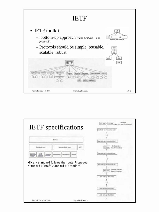
IETF specifications
•Every standard follows the route Proposed standard-> Draft Standard-> Standard
3
Raimo Kantola –S- 2004 Signaling Protocols 12 - 5
ETSI, etc have delegated the 3G standardisation work to 3GPP
• 3GPP – is the 3G Partnership Project• this gives a key role to vendors• site: www.3gpp.org has all their
documents!• The idea is that ETSI etc will rubberstamp
3G documents as standards.
Raimo Kantola –S- 2004 Signaling Protocols 12 - 6
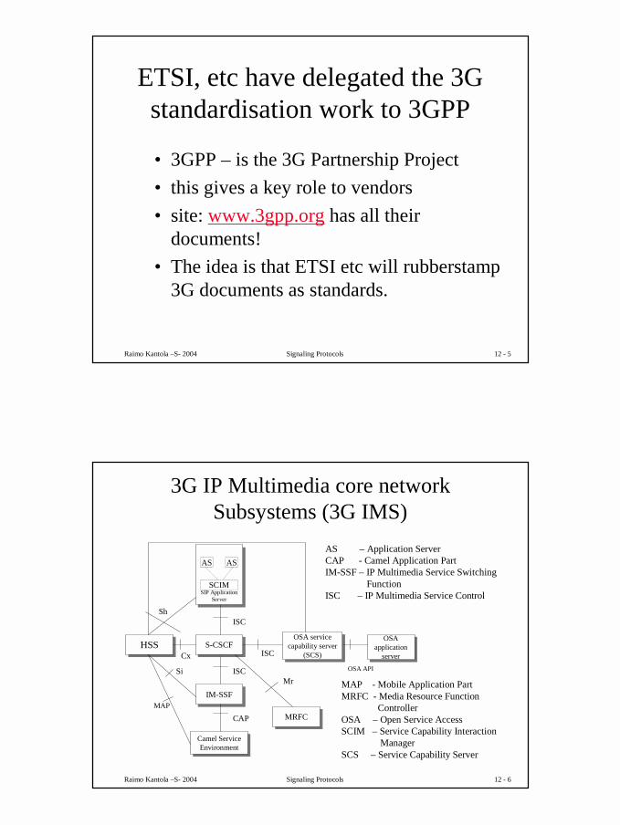
3G IP Multimedia core network Subsystems (3G IMS)
S-CSCFS-CSCF
SIP Application Server
SIP Application Server
HSSHSS OSA service capability server
(SCS)
OSA service capability server
(SCS)
IM-SSFIM-SSF
Camel Service Environment
Camel Service Environment
OSA application
server
OSA application
server
ISC
Cx ISC
ISC
CAPMAP
OSA API
SCIM
AS AS
Sh
Si
MRFCMRFC
Mr
AS – Application ServerCAP - Camel Application PartIM-SSF – IP Multimedia Service Switching
FunctionISC – IP Multimedia Service Control
MAP - Mobile Application PartMRFC - Media Resource Function
ControllerOSA – Open Service AccessSCIM – Service Capability Interaction
ManagerSCS – Service Capability Server
4
Raimo Kantola –S- 2004 Signaling Protocols 12 - 7
3G Application Triggering
Application Server
Service Logic
Service Platform Trigger PointsService Platform Trigger Points
SIP InterfaceHSS
S - CSCF
S P T P
Filter Criteria
sFC SIP
SIPSIP
iFC
iFC – Initial Filter CriteriasFC – Subsequent Filter CriteriaSPT – Service Point Trigger
Service processing can be delegated to Application Servers with a fine grained control
Raimo Kantola –S- 2004 Signaling Protocols 12 - 8
Media processing in 3GAS
ISC
S-CSCF MRFC
MRFP
Mr
Mp
MRFC - Media Resource Function Controller
MRFP – Media Resource FunctionProcessor
All this takes place in the IP domain.Examples:- transcoding Wideband AMR/
Narrowband AMR codec- Multiparty conference media processing
In practice it is convenient to implementMRFP in the same device as the MediaGateway between CS/PS domains
MRFC likely to have a general purposeprocessor,MRFP has many DSPs – digital signalprocessors.
5
Raimo Kantola –S- 2004 Signaling Protocols 12 - 9
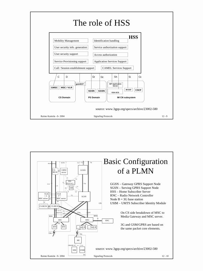
The role of HSS
IM CN subsystem
CxC ShGr GcD
MSC / VLRGMSC
CS Domain
SGSN GGSN
PS Domain
SIP ApplicationServer
CSCF
HSSMobility Management
User security info. generation
User security support
Service Provisioning support
Identification handling
Service authorization support
Access authorization
Call / Session establishment support
Si
IM-SSFOSA-SCS
Application Services Support
gsmSCF
CAMEL Services Support
source: www.3gpp.org/specs/archive/23002-580
Raimo Kantola –S- 2004 Signaling Protocols 12 - 10
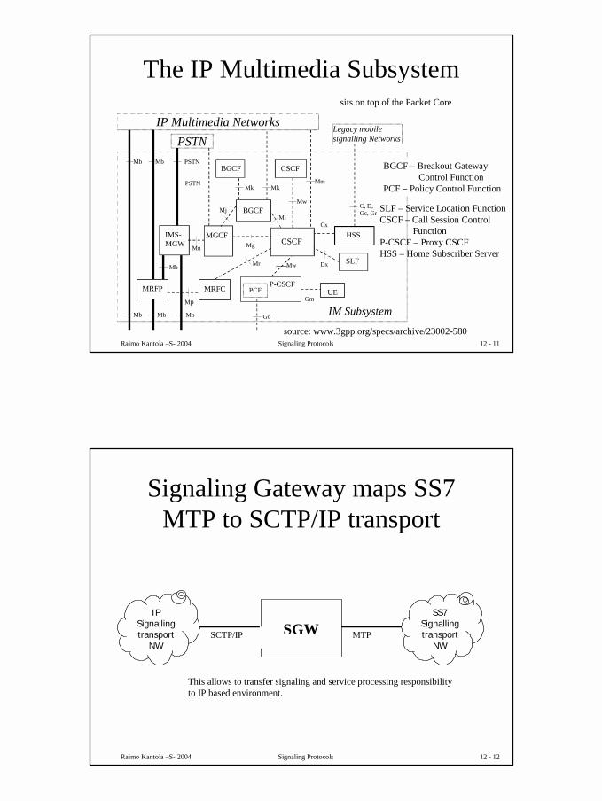
Basic Configuration of a PLMN
BSS
BSC
RNS
RNC
CN
Node B Node B
IuCS IuPS
Iur
Iub
USIM
ME
MS
Cu
Uu
MSC serverSGSN
Gs
GGSNGMSCserver
Gn
HSS (HLR,AuC)
Gr
GcC
D
E
EIR
F Gf
GiPSTN
IuCSIuPS
VLRB
Gp
VLRG
BTSBTS
Um
RNC
Abis
SIM
SIM-ME i/f or
MSC serverB
PSTN
cell
CS-MGWCS-MGW
CS-MGW
Nb
McMc
Nb
PSTNPSTN
Nc
Mc
A Gb
Go
Nc
GGSN – Gateway GPRS Support NodeSGSN – Serving GPRS Support NodeHSS – Home Subscriber ServerRNC – Radio Network ControllerNode B = 3G base stationUSIM – UMTS Subscriber Identity Module
source: www.3gpp.org/specs/archive/23002-580
On CS side breakdown of MSC toMedia Gateway and MSC server.
3G and GSM/GPRS are based onthe same packet core elements.
6
Raimo Kantola –S- 2004 Signaling Protocols 12 - 11
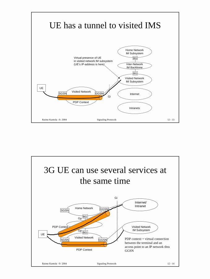
The IP Multimedia Subsystem
P-CSCF
IM Subsystem
CSCF MGCF HSS
Cx
IP Multimedia Networks
IMS-MGW
PSTN
Mn
Mb
Mg
Mm
MRFP
Mb
Mr
Mb
Legacy mobile signalling Networks
CSCF
Mw
Go
PCF
Mw
Gm
BGCF Mj Mi
BGCF
Mk Mk
C, D, Gc, Gr
UE
Mb
Mb
Mb
MRFC
SLF Dx
Mp
PSTN
PSTN
BGCF – Breakout GatewayControl Function
PCF – Policy Control Function
source: www.3gpp.org/specs/archive/23002-580
sits on top of the Packet Core
SLF – Service Location FunctionCSCF – Call Session Control
FunctionP-CSCF – Proxy CSCFHSS – Home Subscriber Server
Raimo Kantola –S- 2004 Signaling Protocols 12 - 12
Signaling Gateway maps SS7 MTP to SCTP/IP transport
SGWSCTP/IP MTP
IPSignallingtransport
NW
SS7Signallingtransport
NW
This allows to transfer signaling and service processing responsibilityto IP based environment.
7
Raimo Kantola –S- 2004 Signaling Protocols 12 - 13
UE has a tunnel to visited IMS
Home NetworkIM Subsystem
Visited NetworkIM Subsystem
Inter-NetworkIM Backbone
Internet
Intranets
UE
GGSN
BG
BG
SGSN
PDP Context
Visited Network
Gi
Virtual presence of UEin visited network IM subsystem(UE’s IP-address is here)
Raimo Kantola –S- 2004 Signaling Protocols 12 - 14
3G UE can use several services at the same time
PDP Context
PDP Context Gp
Internet/ Intranet
Visited Network
Home Network
BG
BG
GGSN
Gp
Gi
SGSN
SGSN GGSN
UE
Visited Network IM Subsystem
PDP context = virtual connectionbetween the terminal and anaccess point to an IP network thruGGSN
8
Raimo Kantola –S- 2004 Signaling Protocols 12 - 15
ETSI SoftSwitch Architecture for NGN
ServiceSwitchingPoint(SSP)
IntegratedServiceNode
SignalingGateway
ServiceControl
Point (SCP)
INAP
ISUP or other
Circuit Switched Network
Voice MediaGateway
MediaGateway
Controller
InterfaceAdapter
API
API
SS7 over IP
MEGACO or MGCP
API
SIP Server
Voice over RTP
SIP
SIP
API
ServiceApplicationService
ApplicationServiceApplication
Parlay
This is the wireline networkingframework
Raimo Kantola –S- 2004 Signaling Protocols 12 - 16
The UMTS terminal functional modelBrowser Streaming Point-to-Point
Raimo Kantola –S- 2004 Signaling Protocols 12 - 17
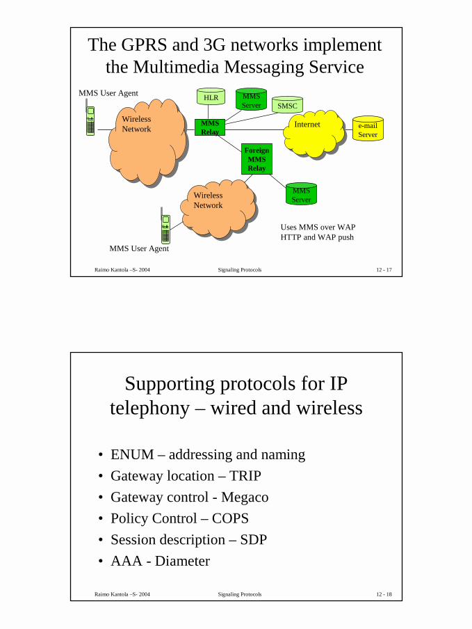
The GPRS and 3G networks implement the Multimedia Messaging Service
MMSRelay
WirelessNetwork
WirelessNetwork
MMSServer SMSC
HLR
ForeignMMSRelay
MMSServer
MMS User Agent
WirelessNetwork
WirelessNetwork
MMS User Agent
InternetInternet e-mailServer
Uses MMS over WAPHTTP and WAP push
Raimo Kantola –S- 2004 Signaling Protocols 12 - 18
Supporting protocols for IP telephony – wired and wireless
• ENUM – addressing and naming• Gateway location – TRIP• Gateway control - Megaco• Policy Control – COPS• Session description – SDP• AAA - Diameter
10
Raimo Kantola –S- 2004 Signaling Protocols 12 - 19
Naming and Addressing in NGN and 3G IMS vs. Telephone numbering
• A Name identifies a domain, a user or a service. An address points to a user or to an interface or to an inlet/outlet in a network.
• Internet heavily relies on the Domain Name System (DNS) to translate names to addresses. The specs of using DNS for Telephony names and addresses is called ENUM –tElephone-NUmber-Mapping.
• ENUM was originally meant for mapping IP telehone numbers (e.g. 3G IMS phonenumbers) to logical names (and IP addresses).
• With Naming and Addressing, at the same time we need to solve the problem of Gateway (CSN/IP) location and Number Portability across the technology boundary.
Raimo Kantola –S- 2004 Signaling Protocols 12 - 20
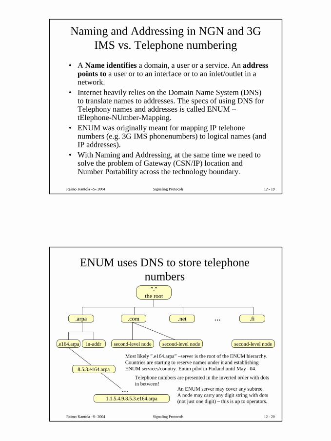
Most likely ”.e164.arpa” –server is the root of the ENUM hierarchy. Countries are starting to reserve names under it and establishingENUM services/country. Enum pilot in Finland until May –04.
Telephone numbers are presented in the inverted order with dots in between!
An ENUM server may cover any subtree.A node may carry any digit string with dots(not just one digit) – this is up to operators.
11
Raimo Kantola –S- 2004 Signaling Protocols 12 - 21
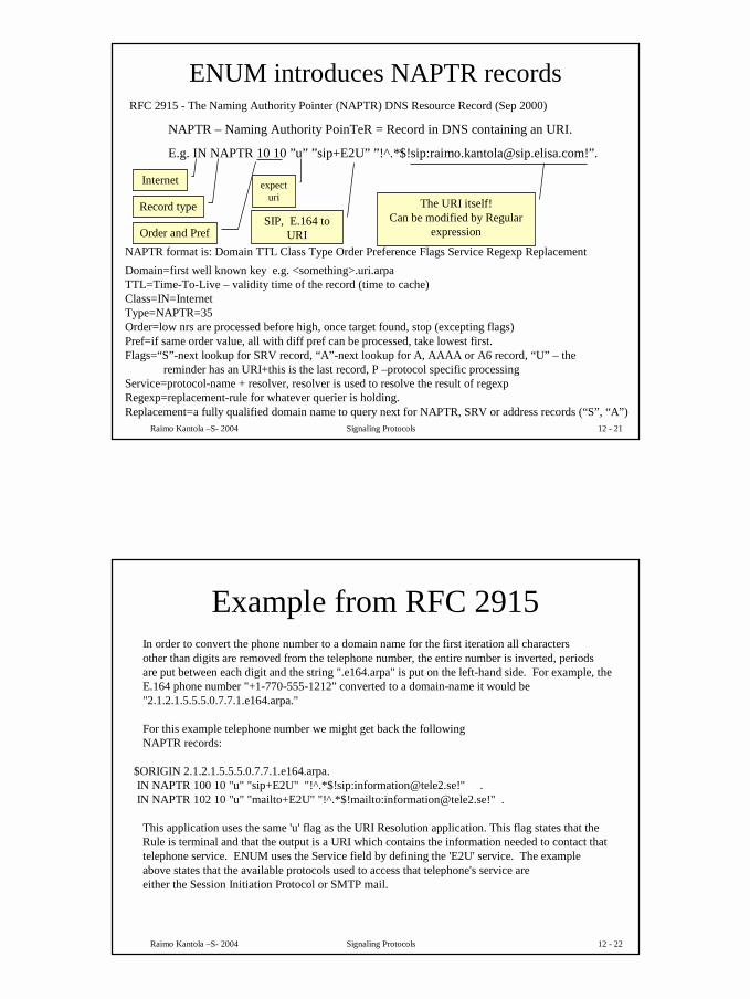
ENUM introduces NAPTR records
NAPTR – Naming Authority PoinTeR = Record in DNS containing an URI.
RFC 2915 - The Naming Authority Pointer (NAPTR) DNS Resource Record (Sep 2000)
NAPTR format is: Domain TTL Class Type Order Preference Flags Service Regexp ReplacementDomain=first well known key e.g. <something>.uri.arpa TTL=Time-To-Live – validity time of the record (time to cache)Class=IN=InternetType=NAPTR=35Order=low nrs are processed before high, once target found, stop (excepting flags)Pref=if same order value, all with diff pref can be processed, take lowest first.Flags=“S”-next lookup for SRV record, “A”-next lookup for A, AAAA or A6 record, “U” – the
reminder has an URI+this is the last record, P –protocol specific processingService=protocol-name + resolver, resolver is used to resolve the result of regexpRegexp=replacement-rule for whatever querier is holding.Replacement=a fully qualified domain name to query next for NAPTR, SRV or address records (“S”, “A”)
Raimo Kantola –S- 2004 Signaling Protocols 12 - 22
Example from RFC 2915In order to convert the phone number to a domain name for the first iteration all charactersother than digits are removed from the telephone number, the entire number is inverted, periods are put between each digit and the string ".e164.arpa" is put on the left-hand side. For example, theE.164 phone number "+1-770-555-1212" converted to a domain-name it would be "2.1.2.1.5.5.5.0.7.7.1.e164.arpa."
For this example telephone number we might get back the followingNAPTR records:
This application uses the same 'u' flag as the URI Resolution application. This flag states that the Rule is terminal and that the output is a URI which contains the information needed to contact thattelephone service. ENUM uses the Service field by defining the 'E2U' service. The example above states that the available protocols used to access that telephone's service areeither the Session Initiation Protocol or SMTP mail.
12
Raimo Kantola –S- 2004 Signaling Protocols 12 - 23
A possible ENUM hierarchyThis follows the ”US model” suggested by Tuomo Rostela for Finland.
$ORIGIN e164.arpa.1 IN NS att_enum.com.
6.4 IN NS sweden_enum.se.8.5.3 IN NS ficora_enum.fi.
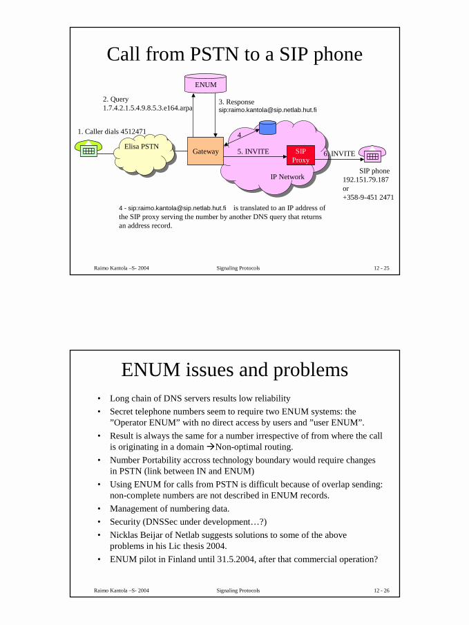
4 - sip:[email protected] is translated to an IP address ofthe SIP proxy serving the number by another DNS query that returnsan address record.
4
Raimo Kantola –S- 2004 Signaling Protocols 12 - 26
ENUM issues and problems• Long chain of DNS servers results low reliability• Secret telephone numbers seem to require two ENUM systems: the
”Operator ENUM” with no direct access by users and ”user ENUM”.• Result is always the same for a number irrespective of from where the call
is originating in a domain �Non-optimal routing.• Number Portability accross technology boundary would require changes
in PSTN (link between IN and ENUM)• Using ENUM for calls from PSTN is difficult because of overlap sending:
non-complete numbers are not described in ENUM records.• Management of numbering data.• Security (DNSSec under development…?)• Nicklas Beijar of Netlab suggests solutions to some of the above
problems in his Lic thesis 2004.• ENUM pilot in Finland until 31.5.2004, after that commercial operation?
14
Raimo Kantola –S- 2004 Signaling Protocols 12 - 27
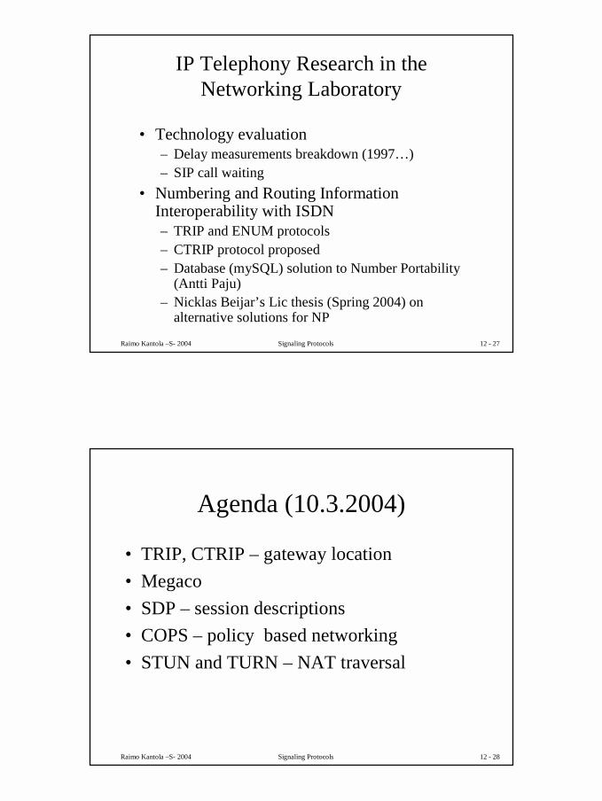
IP Telephony Research in the Networking Laboratory
• Numbering and Routing Information Interoperability with ISDN– TRIP and ENUM protocols– CTRIP protocol proposed– Database (mySQL) solution to Number Portability
(Antti Paju)– Nicklas Beijar’s Lic thesis (Spring 2004) on
alternative solutions for NP
Raimo Kantola –S- 2004 Signaling Protocols 12 - 28
Raimo Kantola –S- 2004 Signaling Protocols 12 - 29
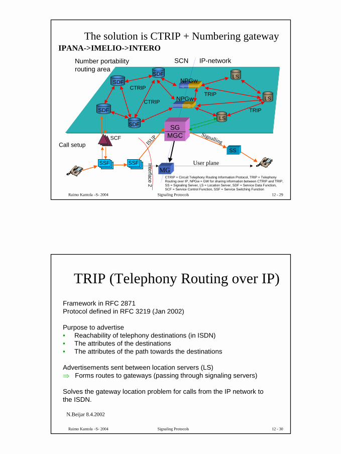
The solution is CTRIP + Numbering gateway
MG
LSTRIP
CTRIP
CTRIP
Interface 2
SCF
SSF SSF
SS
SDF
SDF LS
LS
SCN IP-network
TRIP
Call setup
Number portabilityrouting area
CTRIP = Circuit Telephony Routing Information Protocol, TRIP = Telephony Routing over IP, NPGw = GW for sharing information between CTRIP and TRIP, SS = Signaling Server, LS = Location Server, SDF = Service Data Function, SCF = Service Control Function, SSF = Service Switching Function
NPGw
NPGwSDF
SDF
ISUP
User plane
Signalling
SGMGC
IPANA->IMELIO->INTERO
Raimo Kantola –S- 2004 Signaling Protocols 12 - 30
Framework in RFC 2871Protocol defined in RFC 3219 (Jan 2002)
Purpose to advertise• Reachability of telephony destinations (in ISDN)• The attributes of the destinations• The attributes of the path towards the destinations
Advertisements sent between location servers (LS)� Forms routes to gateways (passing through signaling servers)
Solves the gateway location problem for calls from the IP network to the ISDN.
TRIP (Telephony Routing over IP)
N.Beijar 8.4.2002
16
Raimo Kantola –S- 2004 Signaling Protocols 12 - 31
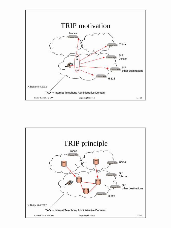
TRIP motivation
SIPSIP09xxxx09xxxx
SIPSIPother destinationsother destinations
H.323H.323
ppoolliiccyy
ITAD (= Internet Telephony Administrative Domain)ITAD (= Internet Telephony Administrative Domain)
FranceFrance
ChinaChina
N.Beijar 8.4.2002
Raimo Kantola –S- 2004 Signaling Protocols 12 - 32
TRIP principle
SIPSIP09xxxx09xxxx
SIPSIPother destinationsother destinations
H.323H.323
ITAD (= Internet Telephony Administrative Domain)ITAD (= Internet Telephony Administrative Domain)
FranceFrance
ChinaChina
N.Beijar 8.4.2002
17
Raimo Kantola –S- 2004 Signaling Protocols 12 - 33
Interdomain distribution between ITADs• Based on BGP-4 (Border Gateway Protocol)• Gateway selection driven by policies
Intradomain synchronization within the ITAD• Based on OSPF, SCSP, IS-IS
Information transported as attributes of the UPDATE message• Attributes can be added -> Expandable• Flags control how unrecognized attributes are handled
Independent of signaling protocol
TRIP
N.Beijar 8.4.2002
Raimo Kantola –S- 2004 Signaling Protocols 12 - 34
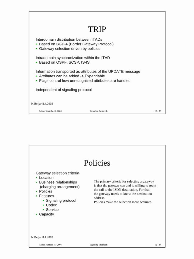
Gateway selection criteria• Location• Business relationships
(charging arrangement)• Policies• Features
• Signaling protocol• Codec• Service
• Capacity
Policies
N.Beijar 8.4.2002
The primary criteria for selecting a gatewayis that the gateway can and is willing to route the call to the ISDN destination. For thatthe gateway needs to know the destinationaddress.Policies make the selection more accurate.
18
Raimo Kantola –S- 2004 Signaling Protocols 12 - 35
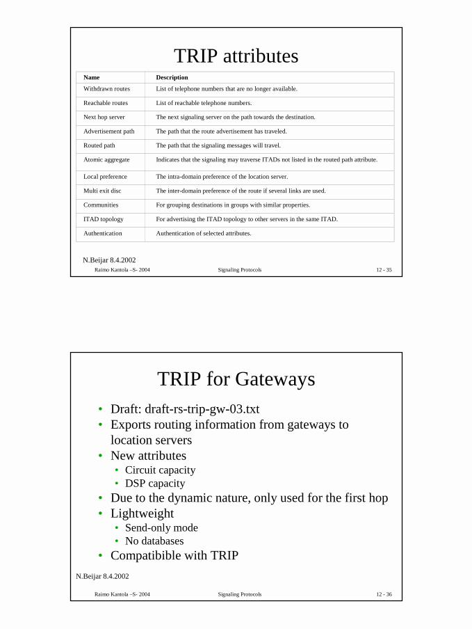
Name
Withdrawn routes
Reachable routes
Next hop server
Advertisement path
Routed path
Atomic aggregate
Local preference
Multi exit disc
Communities
ITAD topology
Authentication
Description
List of telephone numbers that are no longer available.
List of reachable telephone numbers.
The next signaling server on the path towards the destination.
The path that the route advertisement has traveled.
The path that the signaling messages will travel.
Indicates that the signaling may traverse ITADs not listed in the routed path attribute.
The intra-domain preference of the location server.
The inter-domain preference of the route if several links are used.
For grouping destinations in groups with similar properties.
For advertising the ITAD topology to other servers in the same ITAD.
Authentication of selected attributes.
TRIP attributes
N.Beijar 8.4.2002
Raimo Kantola –S- 2004 Signaling Protocols 12 - 36
TRIP for Gateways• Draft: draft-rs-trip-gw-03.txt• Exports routing information from gateways to
location servers• New attributes
• Circuit capacity• DSP capacity
• Due to the dynamic nature, only used for the first hop• Lightweight
• Send-only mode• No databases
• Compatibible with TRIPN.Beijar 8.4.2002
19
Raimo Kantola –S- 2004 Signaling Protocols 12 - 37
Megaco - Media Gateway Control protocol controls Media Gateways and Media Processing
• MGCP was promoted by Cablelabs = US CATV R&D body as the CATV Telephony standard
• ITU-T has its own variant called Megaco=H.248• Megaco, MGCP are master-slave protocols by
which media gateways can be configured e.g to services - in case of residential media gateway, MGCP becomes a subscriber signalling system
Raimo Kantola –S- 2004 Signaling Protocols 12 - 38
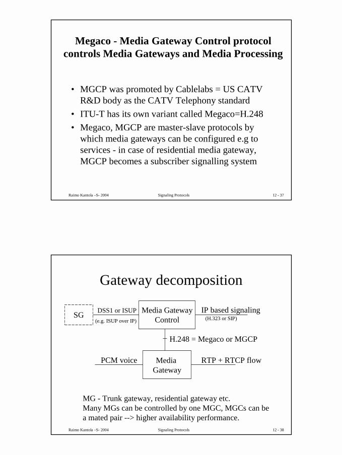
Gateway decomposition
Media GatewayControl
Media Gateway
H.248 = Megaco or MGCP
RTP + RTCP flowPCM voice
DSS1 or ISUP IP based signaling
MG - Trunk gateway, residential gateway etc.Many MGs can be controlled by one MGC, MGCs can bea mated pair --> higher availability performance.
(H.323 or SIP)(e.g. ISUP over IP)SG
20
Raimo Kantola –S- 2004 Signaling Protocols 12 - 39
Megaco functions
• Establishment of connections between terminations– PCM –timeslots for voice– ephemeral packet stream terminations: IP-
address + source + dest UDP-port number• Release of connections• separation of signaling from voice band in
case of CAS and analogue subsc signaling
Raimo Kantola –S- 2004 Signaling Protocols 12 - 40
Current ArchitectureCurrent ArchitectureCurrent Architecture
MG
LS
TRIP
SS
LS
TRIP = Telephony Routing over IP, SG - Signalling Gateway, MGC - Media Gateway ControllerMG - Media Gateway, SS = Signaling Server, LS = Location Server
LS
SCNISUP/H.323/SIP
IP
SS
Megaco
MGCSG
21
Raimo Kantola –S- 2004 Signaling Protocols 12 - 41
SCN IP
MG
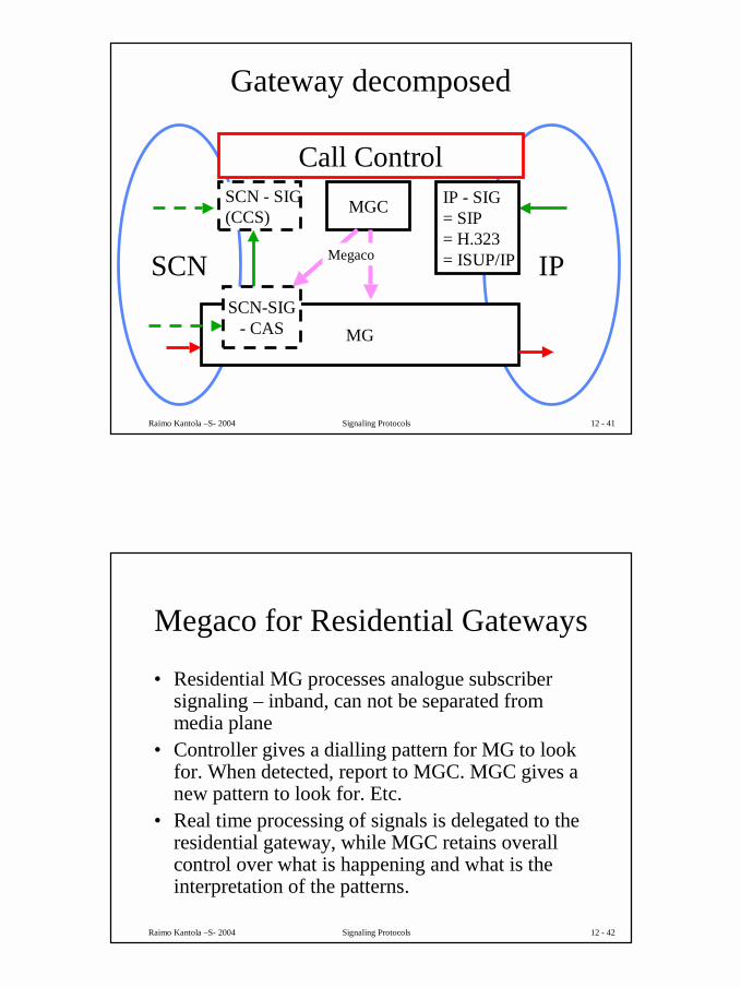
Gateway decomposed
SCN - SIG(CCS)
Call ControlMGC IP - SIG
= SIP= H.323= ISUP/IP
SCN-SIG- CAS
Megaco
Raimo Kantola –S- 2004 Signaling Protocols 12 - 42
Megaco for Residential Gateways
• Residential MG processes analogue subscriber signaling – inband, can not be separated from media plane
• Controller gives a dialling pattern for MG to look for. When detected, report to MGC. MGC gives a new pattern to look for. Etc.
• Real time processing of signals is delegated to the residential gateway, while MGC retains overall control over what is happening and what is the interpretation of the patterns.
22
Raimo Kantola –S- 2004 Signaling Protocols 12 - 43
QoS – Integrated Serv. and DiffServ help resolving the QoS issue in VOIP and 3G IMS
• Integrated Services– Different treatment to different flows– State info stored in network, routers examine packets!!!(not good)– Reservation merging– RSVP protocol – for reservation of resources
• DiffServ– Defines a small nrof traffic classes with different priority levels– Packets tagged with level tags at the beginning(ingress)– Routers just examine tags– Better scaling– Requires policy management: e.g. which packets to assign to
which class.
Raimo Kantola –S- 2004 Signaling Protocols 12 - 44
SIP Sessions require policy control
• Parties can release the “call session” but since they have obtained each others IP-addresses, they can continue sending media streams to each other!!
• How to push INVITE to B-party, if B-party does not have a permanent IP address which is most often the case!
Integration ofProxy withFirewall andNAT
23
Raimo Kantola –S- 2004 Signaling Protocols 12 - 45
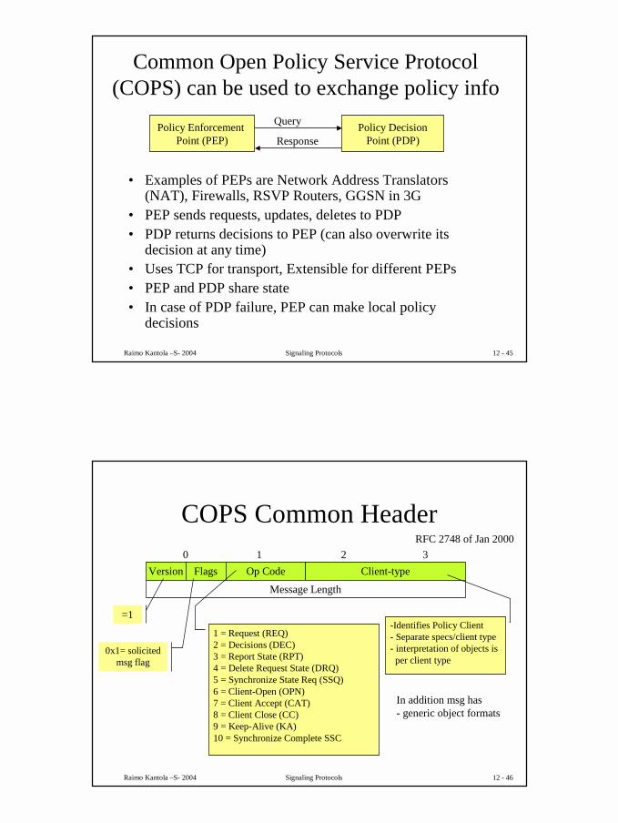
Common Open Policy Service Protocol (COPS) can be used to exchange policy info
• Examples of PEPs are Network Address Translators (NAT), Firewalls, RSVP Routers, GGSN in 3G
• PEP sends requests, updates, deletes to PDP• PDP returns decisions to PEP (can also overwrite its
decision at any time)• Uses TCP for transport, Extensible for different PEPs• PEP and PDP share state• In case of PDP failure, PEP can make local policy
decisions
Policy Enforcement Point (PEP)
Policy DecisionPoint (PDP)
Query
Response
Raimo Kantola –S- 2004 Signaling Protocols 12 - 46
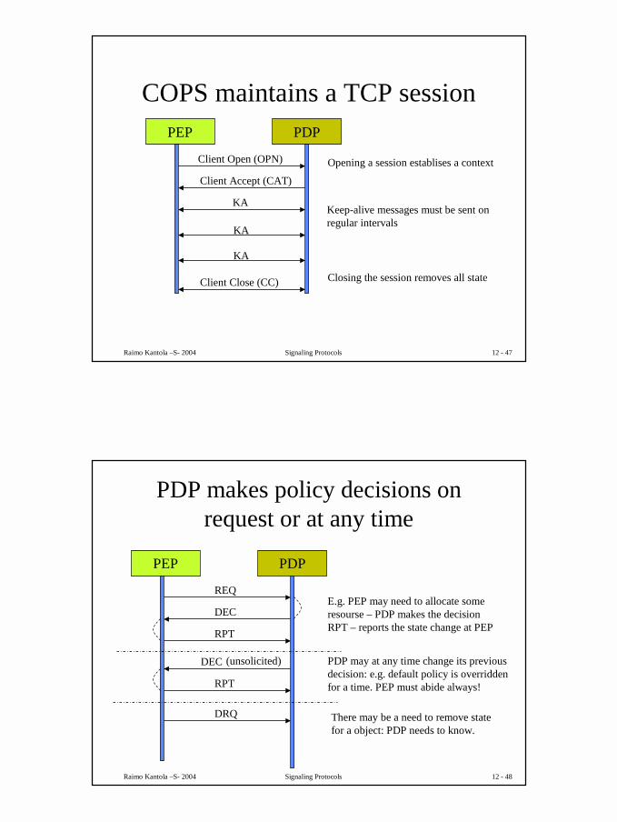
COPS Common Header
Version Flags Op Code Client-type0 1 2 3
Message Length
RFC 2748 of Jan 2000
=1
0x1= solicited msg flag
1 = Request (REQ)2 = Decisions (DEC)3 = Report State (RPT)4 = Delete Request State (DRQ)5 = Synchronize State Req (SSQ)6 = Client-Open (OPN)7 = Client Accept (CAT)8 = Client Close (CC)9 = Keep-Alive (KA)10 = Synchronize Complete SSC
-Identifies Policy Client- Separate specs/client type- interpretation of objects is
per client type
In addition msg has- generic object formats
24
Raimo Kantola –S- 2004 Signaling Protocols 12 - 47
COPS maintains a TCP sessionPEP PDP
Client Open (OPN)
Client Accept (CAT)
KA
KA
KA
Client Close (CC)
Opening a session establises a context
Keep-alive messages must be sent onregular intervals
Closing the session removes all state
Raimo Kantola –S- 2004 Signaling Protocols 12 - 48
PDP makes policy decisions on request or at any time
PEP PDP
REQ
DEC
RPT
DEC
RPT
(unsolicited)
DRQ
E.g. PEP may need to allocate someresourse – PDP makes the decisionRPT – reports the state change at PEP
PDP may at any time change its previousdecision: e.g. default policy is overriddenfor a time. PEP must abide always!
There may be a need to remove statefor a object: PDP needs to know.
25
Raimo Kantola –S- 2004 Signaling Protocols 12 - 49
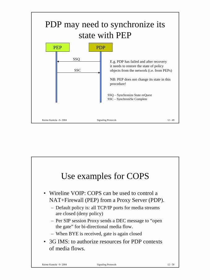
PDP may need to synchronize its state with PEP
PEP PDP
SSQ
SSC
E.g. PDP has failed and after recoveryit needs to restore the state of policyobjects from the network (i.e. from PEPs)
NB: PEP does not change its state in thisprocedure!
SSQ – Synchronize State reQuestSSC – SynchroniSe Complete
Raimo Kantola –S- 2004 Signaling Protocols 12 - 50
Use examples for COPS
• Wireline VOIP: COPS can be used to control a NAT+Firewall (PEP) from a Proxy Server (PDP).– Default policy is: all TCP/IP ports for media streams
are closed (deny policy)– Per SIP session Proxy sends a DEC message to “open
the gate” for bi-directional media flow.– When BYE is received, gate is again closed
• 3G IMS: to authorize resources for PDP contexts of media flows.
26
Raimo Kantola –S- 2004 Signaling Protocols 12 - 51
SDP: Session Description Protocol • SDP was initially designed for Mbone. Mbone
was/is a multicast overlay network on the Internet• Used to describe sessions (to link the session with
media tools)• Describes conference/session addresses and ports
+ other parameters needed by RTP, RTSP and other media tools
• SDP is carried by SIP, SAP: Session Announcement Protocol etc.
Raimo Kantola –S- 2004 Signaling Protocols 12 - 52
Multicast• Several parties involved
– IPv4 Multicast from 224.0.0.0 – 239.255.255.255• Saves bandwidth cmp to n times p2p connection• Entity that is sending does not have to know all the participants• Multicast Routing protocols
– Dense Mode (shortest-path tree per sender)– Sparse Mode (shared tree used by all sources)
• IGMP (Internet Group Management Protocol)– For hosts that want to become part of multicast group
• Mbone – part of Internet that supports multicast• RTP – transport of real-time data such as voice or video
– Sequence number, timestamps• RTCP – controls RTP transport (every RTP session has a parallel
RTCP session.)
27
Raimo Kantola –S- 2004 Signaling Protocols 12 - 53
SDP can describe• Session name and purpose• Time(s) the session is active
– start, stop time, repetition
• The media comprising the session– video, audio, etc– transport protocol: RTP, UDP, IP, H.320 etc
• Parameters to receive media: addresses, ports, formats etc.– H.261 video, MPEG video, PCMU law audio, AMR audio
• Approximate bandwidth needed for the session• Contact info for person responsible
Raimo Kantola –S- 2004 Signaling Protocols 12 - 54
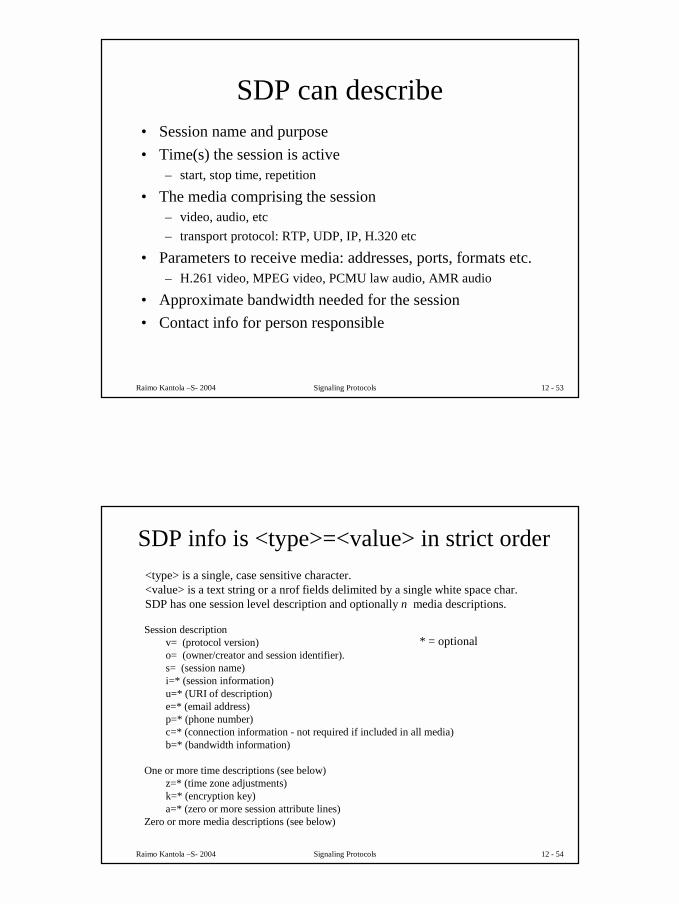
SDP info is <type>=<value> in strict order<type> is a single, case sensitive character. <value> is a text string or a nrof fields delimited by a single white space char.SDP has one session level description and optionally n media descriptions.
Session descriptionv= (protocol version)o= (owner/creator and session identifier).s= (session name)i=* (session information)u=* (URI of description)e=* (email address)p=* (phone number)c=* (connection information - not required if included in all media)b=* (bandwidth information)
One or more time descriptions (see below)z=* (time zone adjustments)k=* (encryption key)a=* (zero or more session attribute lines)
Zero or more media descriptions (see below)
* = optional
28
Raimo Kantola –S- 2004 Signaling Protocols 12 - 55
SDP items continuedTime description
t= (time the session is active)r=* (zero or more repeat times)
Media descriptionm= (media name and transport address)i=* (media title)c=* (connection information - optional if included at session-level)b=* (bandwidth information)k=* (encryption key)a=* (zero or more media attribute lines)
3G document refer to a newer SDP- draft from may 2002.
RFC 2327: SDP Session Description Protocol (dated 1998), now Proposed StdRFC 3407: SDP Simple Capability DeclarationRFC 3264 - An Offer/Answer Model with Session Description Protocol (SDP)RFC 3266 - Support for IPv6 in Session Description Protocol (SDP)RFC 3556 SDP Bandwidth modifiers for RTCP
Some SDP documents:
Raimo Kantola –S- 2004 Signaling Protocols 12 - 56
NAT Traversal
• For the purpose of IPv4 address saving, many users sit behind Network Address Translators.
• NATs are of 4 types: Full Cone, Restricted Cone, Port Restricted Cone and Symmetric.
• NAT address/port mappings will be dropped after some time of not seeing packets thru the mapping
RFC 3489 Title: STUN - Simple Traversal of User Datagram Protocol (UDP) Through Network Address Translators (NATs) Author(s): J. Rosenberg, J. Weinberger, C. Huitema, R. MahyStatus: Standards Track Date: March 2003
See also: http://corp.deltathree.com/technology/nattraversalinsip.pdf Traversal Using Relay NAT (TURN) draft-rosenberg-midcom-turn-03
Internet is an A-subscriber’s Network! B-subscribers are not connected!
29
Raimo Kantola –S- 2004 Signaling Protocols 12 - 57
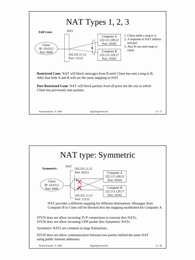
NAT Types 1, 2, 3
ClientIP: 10.0.0.2Port: 8000
NAT
Computer A222.111.109.21
Port: 20202
Computer B222.111.129.17
Port: 10101202.231.11.12Port: 12123
Full Cone:1. Client sends a msg to A2. A responds to NAT address
and port3. Also B can send msgs to
client
Restricted Cone: NAT will block messages from B until Client has sent a msg to B,After that both A and B will see the same mapping in NAT
Port Restricted Cone: NAT will block packets from all ports but the one to whichClient has previously sent packets.
Raimo Kantola –S- 2004 Signaling Protocols 12 - 58
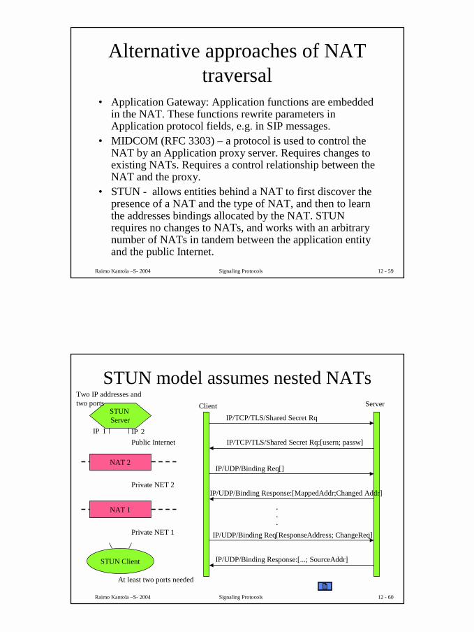
NAT type: Symmetric
ClientIP: 10.0.0.2Port: 8000
NAT
Computer A222.111.109.21
Port: 20202
Computer B222.111.129.17
Port: 10101202.231.11.12Port: 12123
Symmetric: 202.231.11.12Port: 43211
NAT provides a different mapping for different destinations. Messages fromComputer B to Cient will be blocked thru the mapping established for Computer A.
STUN does not allow incoming TCP connections to traverse thru NATs,STUN does not allow incoming UDP packet thru Symmetric NATs.
Symmetric NATs are common in large Enterprises.
STUN does not allow communication between two parties behind the same NATusing public Internet addresses.
30
Raimo Kantola –S- 2004 Signaling Protocols 12 - 59
Alternative approaches of NAT traversal
• Application Gateway: Application functions are embedded in the NAT. These functions rewrite parameters in Application protocol fields, e.g. in SIP messages.
• MIDCOM (RFC 3303) – a protocol is used to control the NAT by an Application proxy server. Requires changes to existing NATs. Requires a control relationship between the NAT and the proxy.
• STUN - allows entities behind a NAT to first discover the presence of a NAT and the type of NAT, and then to learn the addresses bindings allocated by the NAT. STUN requires no changes to NATs, and works with an arbitrary number of NATs in tandem between the application entity and the public Internet.
Raimo Kantola –S- 2004 Signaling Protocols 12 - 60
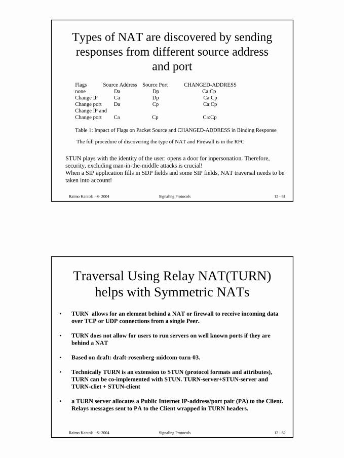
STUN model assumes nested NATs
STUN Client
NAT 1
NAT 2
STUN Server
Private NET 1
Private NET 2
Public Internet
IP/TCP/TLS/Shared Secret RqClient Server
IP/TCP/TLS/Shared Secret Rq:[usern; passw]
IP/UDP/Binding Req[]
IP/UDP/Binding Response:[MappedAddr;Changed Addr]
IP/UDP/Binding Req[ResponseAddress; ChangeReq]
IP/UDP/Binding Response:[...; SourceAddr]
.
.
.
IP 1 IP 2
At least two ports needed
Two IP addresses and two ports
31
Raimo Kantola –S- 2004 Signaling Protocols 12 - 61
Types of NAT are discovered by sending responses from different source address
and portFlags Source Address Source Port CHANGED-ADDRESS none Da Dp Ca:Cp Change IP Ca Dp Ca:Cp Change port Da Cp Ca:Cp Change IP and Change port Ca Cp Ca:Cp
Table 1: Impact of Flags on Packet Source and CHANGED-ADDRESS in Binding Response
The full procedure of discovering the type of NAT and Firewall is in the RFC
STUN plays with the identity of the user: opens a door for inpersonation. Therefore,security, excluding man-in-the-middle attacks is crucial!When a SIP application fills in SDP fields and some SIP fields, NAT traversal needs to betaken into account!
Raimo Kantola –S- 2004 Signaling Protocols 12 - 62
Traversal Using Relay NAT(TURN) helps with Symmetric NATs
• TURN allows for an element behind a NAT or firewall to receive incoming data over TCP or UDP connections from a single Peer.
• TURN does not allow for users to run servers on well known ports if they are behind a NAT
• Based on draft: draft-rosenberg-midcom-turn-03.
• Technically TURN is an extension to STUN (protocol formats and attributes),TURN can be co-implemented with STUN. TURN-server+STUN-server andTURN-cliet + STUN-client
• a TURN server allocates a Public Internet IP-address/port pair (PA) to the Client.Relays messages sent to PA to the Client wrapped in TURN headers.
32
Raimo Kantola –S- 2004 Signaling Protocols 12 - 63
TURN model is similar to STUN
TURN Client
NAT 1
NAT 2
TURN Server
Private NET 1
Private NET 2
Public Internet
IP/TCP/TLS/Shared Secret RqClient Server
IP/TCP/TLS/Shared Secret Rq:[usern; passw]
IP/UDP or TCP/Allocate Req[]
IP/UDP or TCP/Allocate Response:[PA, Lifetime]
IP 1
IP-addr/port pairs for allocation
Send RequestSend Response
Allocate Req[PA....]
Allocate Response:[PA, Lifetime]
¾ of Lifetime
PA
Raimo Kantola –S- 2004 Signaling Protocols 12 - 64
Diameter is the emerging AAA protocol for the Internet and 3G
• Applications include: – Network Access Servers for dial-up with PPP/SLIP, – Mobile IPv4 Foreign Agents, – roaming 3G and Internet users.
• Provides Authentication of users, Authorization and Accounting of use• Carried over TCP or SCTP
ClientNAS: Network Access
ServerMobile IPv4 FAS-CSCF
Agent
RelayProxyRedirect Agent
Servere.g.
-Policy server- HSS
REQ RequestResponseResp
Server Msge.g. stop service now
33
Raimo Kantola –S- 2004 Signaling Protocols 12 - 65
Diameter documentsDiameter Base Protocoldraft-ietf-aaa-diameter-16.txt
Transport Profile (AAATRANS)- transport issues- server failover
Mobile IPv4 (DIAMMIP)-FA
NASREQ- PPP/SLIP access
to Internet
Applications
Diameter Multimedia Application (3GPP)- defined by 3GPP for 3G IMS- Client: S-CSCF or I-CSCF- Server HSS- Ridirect: SLF
Raimo Kantola –S- 2004 Signaling Protocols 12 - 66
Diameter features include- Delivery of attribute value pairs: AVPs- Capability negotiation- Error Notification- Extensibility- Sessions and Accounting
User Authentication
Service specific authentication info ->grant service or not
Resource usage information- accounting and capacity planning is
supported
Relay, proxy and redirect of requeststhru a server hierarchy
34
Raimo Kantola –S- 2004 Signaling Protocols 12 - 67
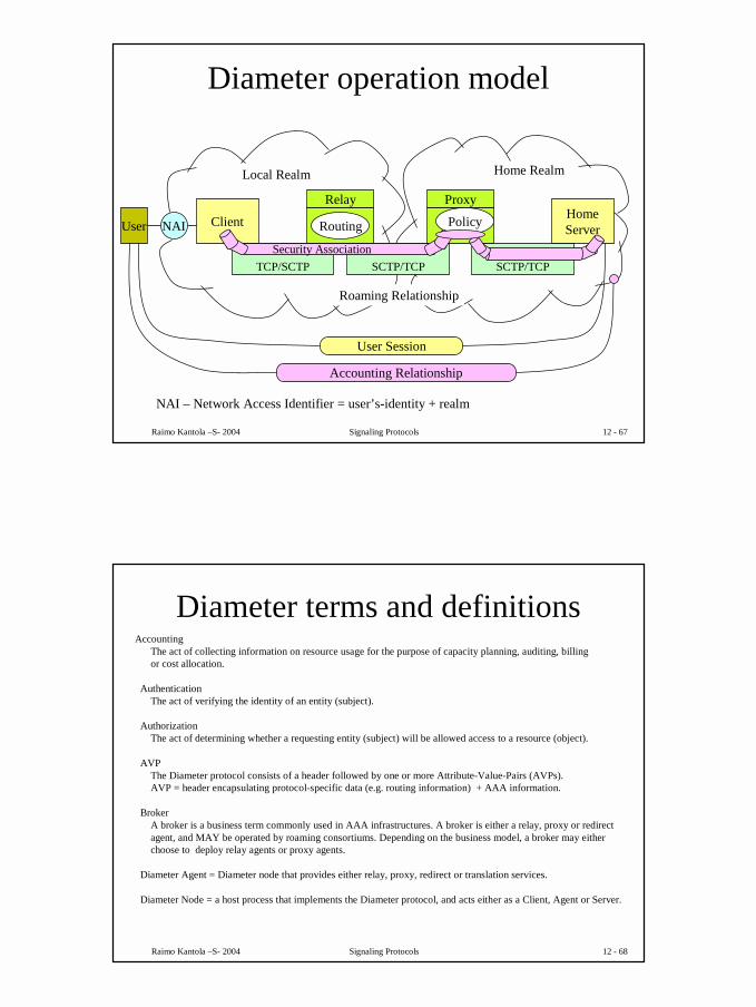
Diameter operation model
Client
Relay
Routing
Proxy
Policy HomeServer
TCP/SCTP SCTP/TCP SCTP/TCPSecurity Association
NAIUser
Local Realm Home Realm
Roaming Relationship
User Session
Accounting Relationship
NAI – Network Access Identifier = user’s-identity + realm
Raimo Kantola –S- 2004 Signaling Protocols 12 - 68
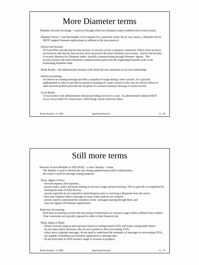
Diameter terms and definitionsAccounting
The act of collecting information on resource usage for the purpose of capacity planning, auditing, billing or cost allocation.
AuthenticationThe act of verifying the identity of an entity (subject).
AuthorizationThe act of determining whether a requesting entity (subject) will be allowed access to a resource (object).
AVPThe Diameter protocol consists of a header followed by one or more Attribute-Value-Pairs (AVPs).AVP = header encapsulating protocol-specific data (e.g. routing information) + AAA information.
BrokerA broker is a business term commonly used in AAA infrastructures. A broker is either a relay, proxy or redirect agent, and MAY be operated by roaming consortiums. Depending on the business model, a broker may either choose to deploy relay agents or proxy agents.
Diameter Agent = Diameter node that provides either relay, proxy, redirect or translation services.
Diameter Node = a host process that implements the Diameter protocol, and acts either as a Client, Agent or Server.
35
Raimo Kantola –S- 2004 Signaling Protocols 12 - 69
More Diameter termsDiameter Security Exchange = a process through which two Diameter nodes establish end-to-end security.
Diameter Server = one that handles AAA requests for a particular realm. By its very nature, a Diameter Server MUST support Diameter applications in addition to the base protocol.
End-to-End SecurityTLS and IPsec provide hop-by-hop security, or security across a transport connection. When relays or proxy are involved, this hop-by-hop security does not protect the entire Diameter user session. End-to-end security is security between two Diameter nodes, possibly communicating through Diameter Agents. Thissecurity protects the entire Diameter communications path from the originating Diameter node to the terminating Diameter node.
Home Realm = the administrative domain with which the user maintains an account relationship.
Interim accountingAn interim accounting message provides a snapshot of usage during a user's session. It is typically implemented in order to provide for partial accounting of a user's session in the case of a device reboot or other network problem prevents the reception of a session summary message or session record.
Local RealmA local realm is the administrative domain providing services to a user. An administrative domain MAY act as a local realm for certain users, while being a home realm for others.
Raimo Kantola –S- 2004 Signaling Protocols 12 - 70
Still more termsNetwork Access Identifier or NAI [NAI] = a user's identity + realm.
The identity is used to identify the user during authentication and/or authorization, the realm is used for message routing purposes.
Proxy Agent or Proxy- forward requests and responses, - proxies make policy decisions relating to resource usage and provisioning. This is typically accomplished by tracking the state of NAS devices.
- proxies typically do not respond to client Requests prior to receiving a Response from the server, - they may originate Reject messages in cases where policies are violated. - proxies need to understand the semantics of the messages passing through them, and - may not support all Diameter applications.
Real-time AccountingReal-time accounting involves the processing of information on resource usage within a defined time window. Time constraints are typically imposed in order to limit financial risk.
Relay Agent or Relay- Relays forward requests and responses based on routing-related AVPs and realm routing table entries. - do not make policy decisions, they do not examine or alter non-routing AVPs.- relays never originate messages, do not need to understand the semantics of messages or non-routing AVPs, - are capable of handling any Diameter application or message type. - do not keep state on NAS resource usage or sessions in progress.
36
Raimo Kantola –S- 2004 Signaling Protocols 12 - 71
The last termsRedirect Agent
- refer clients to servers and allow them to communicate directly. - do not sit in the forwarding path � they do not alter any AVPs transiting between client and server. - do not originate messages and- are capable of handling any message type, although they may be configured only to redirect messages of certain types, while acting as relay or proxy agents for other types.
- do not keep state with respect to sessions or NAS resources.
Roaming RelationshipsRoaming relationships include relationships between companies and ISPs, relationships among peer ISPs within a roaming consortium, and relationships between an ISP and a roaming consortium.
Security AssociationA security association is an association between two endpoints in a Diameter session which allows the endpoints to communicate with integrity and confidentially, even in the presence of relays and/or proxies.
Session = a related progression of events devoted to a particular activity. Each application SHOULD provide guidelines as to when a session begins and ends. All Diameter packets with the same Session-Identifier are part of
the same session.
Sub-session represents a distinct service (e.g. QoS or data characteristics) provided to a given session. These services may happen concurrently (e.g. simultaneous voice and data transfer during the same session) or serially. These changes in sessions are tracked with the Accounting-Sub-Session-Id.
Translation Agent performs protocol translation between Diameter and another AAA protocol,such as RADIUS.
Raimo Kantola –S- 2004 Signaling Protocols 12 - 72
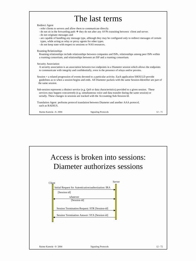
Access is broken into sessions: Diameter authorizes sessions
Initial Request for Autentication/authorization: IRA
[Session-id]
[Session-id]whatever
Session Termination Request: STR [Session-id]
Session Termination Answer: STA [Session-id]
Client Server
37
Raimo Kantola –S- 2004 Signaling Protocols 12 - 73
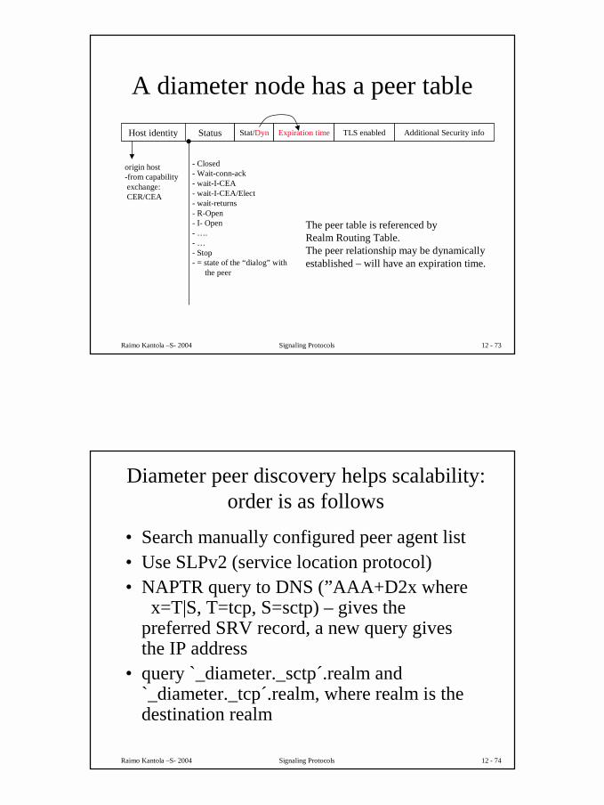
A diameter node has a peer tableHost identity Status Stat/Dyn Expiration time TLS enabled Additional Security info
origin host-from capabilityexchange: CER/CEA
- Closed- Wait-conn-ack- wait-I-CEA- wait-I-CEA/Elect- wait-returns- R-Open- I- Open- ….- …- Stop- = state of the “dialog” with
the peer
The peer table is referenced by Realm Routing Table.The peer relationship may be dynamicallyestablished – will have an expiration time.
Raimo Kantola –S- 2004 Signaling Protocols 12 - 74
Diameter peer discovery helps scalability: order is as follows
• Search manually configured peer agent list• Use SLPv2 (service location protocol)• NAPTR query to DNS (”AAA+D2x where
x=T|S, T=tcp, S=sctp) – gives the preferred SRV record, a new query gives the IP address
• query `_diameter._sctp´.realm and `_diameter._tcp´.realm, where realm is the destination realm
38
Raimo Kantola –S- 2004 Signaling Protocols 12 - 75
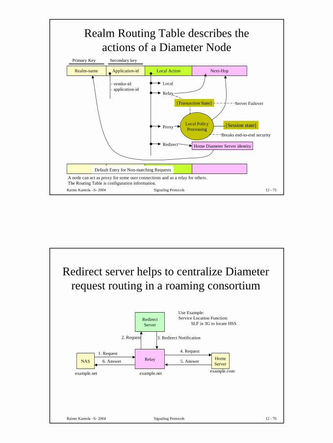
Realm Routing Table describes the actions of a Diameter Node
Realm-name Next-HopLocal ActionApplication-id
- vendor-id- application-id
Local
Relay
ProxyLocal PolicyProcessing
Redirect Home Diameter Server identity
[Session state]
[Transaction State]
Primary Key Secondary key
A node can act as proxy for some user connections and as a relay for others. The Routing Table is configuration information.
Default Entry for Non-matching Requests
Server Failover
Breaks end-to-end security
Raimo Kantola –S- 2004 Signaling Protocols 12 - 76
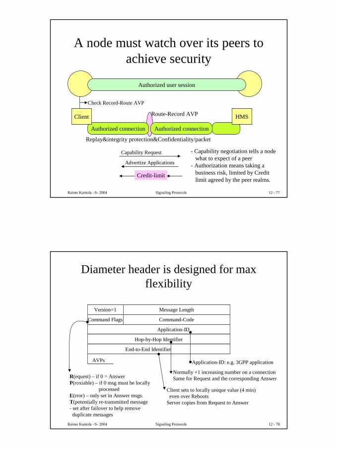
Redirect server helps to centralize Diameter request routing in a roaming consortium
NAS Relay HomeServer
RedirectServer
1. Request
2. Request 3. Redirect Notification
4. Request
5. Answer6. Answer
example.net example.net example.com
Use Example: Service Location Function:
SLF in 3G to locate HSS
39
Raimo Kantola –S- 2004 Signaling Protocols 12 - 77
A node must watch over its peers to achieve security
- IPFilterRule such asaction dir proto from src to dst [options], whereaction =permit|denydir=in|out (in = from the terminal)src/dst = <address/mask> [ports]
You can specify firewall rules in Diameter.
41
Raimo Kantola –S- 2004 Signaling Protocols 12 - 81
A diameter node operation is described as a set of state machines
• Peer state machine• Authorization Session State Machines (4)
– Server maintains session state: client FSM and server FSM
– Server does not maintain session state: client FSM and server FSM
• Accounting Session State Machines– Client state machine– Server state machines: stateless and stateful – may be overridden by applications
Raimo Kantola –S- 2004 Signaling Protocols 12 - 82
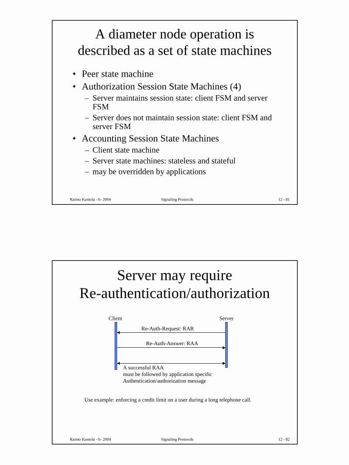
Server may require Re-authentication/authorization
Client Server
Re-Auth-Request: RAR
Re-Auth-Answer: RAA
A successful RAAmust be followed by application specificAuthentication/authorization message
Use example: enforcing a credit limit on a user during a long telephone call.
42
Raimo Kantola –S- 2004 Signaling Protocols 12 - 83
NASREQ defines an authentication and authorization application
draft-ietf-aaa-diameter-nasreq-10.txt of Nov 2002.
Raimo Kantola –S- 2004 Signaling Protocols 12 - 85
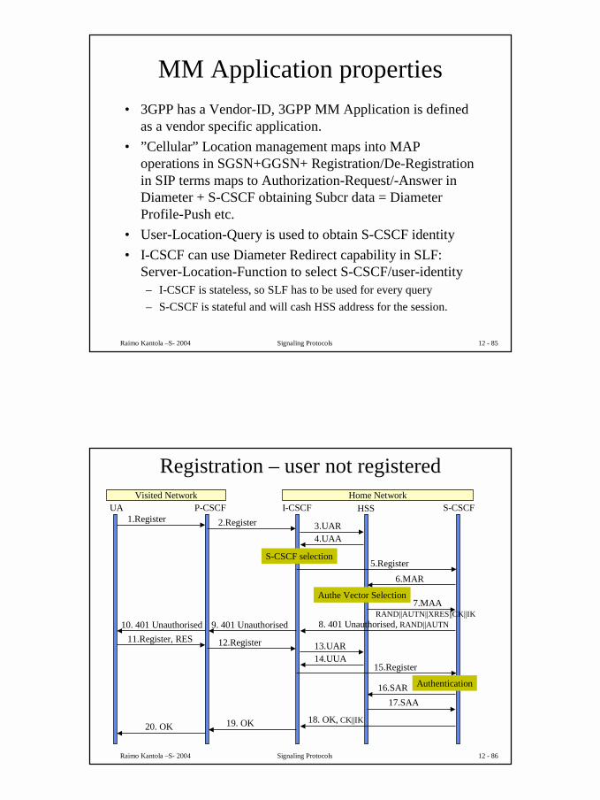
MM Application properties• 3GPP has a Vendor-ID, 3GPP MM Application is defined
as a vendor specific application.• ”Cellular” Location management maps into MAP
operations in SGSN+GGSN+ Registration/De-Registration in SIP terms maps to Authorization-Request/-Answer in Diameter + S-CSCF obtaining Subcr data = Diameter Profile-Push etc.
• User-Location-Query is used to obtain S-CSCF identity• I-CSCF can use Diameter Redirect capability in SLF:
Server-Location-Function to select S-CSCF/user-identity– I-CSCF is stateless, so SLF has to be used for every query– S-CSCF is stateful and will cash HSS address for the session.
Raimo Kantola –S- 2004 Signaling Protocols 12 - 86
Registration – user not registeredVisited Network Home Network
UA P-CSCF I-CSCF HSS S-CSCF1.Register 2.Register 3.UAR
Raimo Kantola –S- 2004 Signaling Protocols 12 - 89
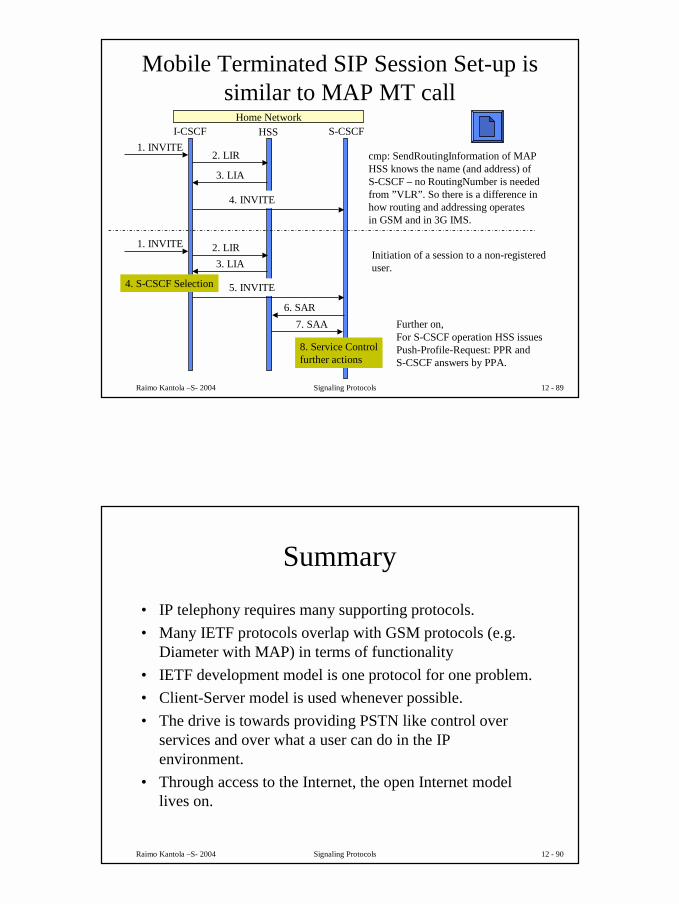
Mobile Terminated SIP Session Set-up is similar to MAP MT call
Home NetworkI-CSCF HSS S-CSCF
1. INVITE
4. INVITE
2. LIR
3. LIA
cmp: SendRoutingInformation of MAPHSS knows the name (and address) ofS-CSCF – no RoutingNumber is neededfrom ”VLR”. So there is a difference inhow routing and addressing operatesin GSM and in 3G IMS.
1. INVITE
5. INVITE
2. LIR3. LIA
4. S-CSCF Selection
6. SAR7. SAA
8. Service Controlfurther actions
Initiation of a session to a non-registereduser.
Further on,For S-CSCF operation HSS issuesPush-Profile-Request: PPR andS-CSCF answers by PPA.
Raimo Kantola –S- 2004 Signaling Protocols 12 - 90
Summary
• IP telephony requires many supporting protocols.• Many IETF protocols overlap with GSM protocols (e.g.
Diameter with MAP) in terms of functionality• IETF development model is one protocol for one problem. • Client-Server model is used whenever possible.• The drive is towards providing PSTN like control over
services and over what a user can do in the IP environment.
• Through access to the Internet, the open Internet model lives on.


![AP1800 3G Router Module for Wired Network Backup [호환 모드] Hardware Specification (3G Router Card) AP1800 Analog/Digital VoIP Gateway VoIP Service over 3G Data Network Internet](https://static.documents.pub/doc/80x56/5e8310c9c1247914013ab1de/ap1800-3g-router-module-for-wired-network-backup-eeoe-hardware-specification.jpg)


