87
GPIB GPIB Reference Manual for VXIpc ™ Embedded Controllers and VxWorks GPIB for VXIpc Controllers and VxWorks December 1997 Edition Part Number 321858A-01
GPIB
GPIB Reference Manual for VXIpc™ Embedded Controllers and VxWorksGPIB for VXIpc Controllers and VxWorks
December 1997 EditionPart Number 321858A-01
725 11, 91, 4 00, 7 1200,
Internet SupportE-mail: [email protected] Site: ftp.natinst.comWeb Address: http://www.natinst.com
Bulletin Board SupportBBS United States: 512 794 5422BBS United Kingdom: 01635 551422BBS France: 01 48 65 15 59
Fax-on-Demand Support512 418 1111
Telephone Support (USA)Tel: 512 795 8248Fax: 512 794 5678
International OfficesAustralia 03 9879 5166, Austria 0662 45 79 90 0, Belgium 02 757 00 20, Brazil 011 288 3336, Canada (Ontario) 905 785 0085, Canada (Québec) 514 694 8521, Denmark 45 76 26 00, Finland 09 725France 01 48 14 24 24, Germany 089 741 31 30, Hong Kong 2645 3186, Israel 03 6120092, Italy 02 4130Japan 03 5472 2970, Korea 02 596 7456, Mexico 5 520 2635, Netherlands 0348 433466, Norway 32 84 8Singapore 2265886, Spain 91 640 0085, Sweden 08 730 49 70, Switzerland 056 200 51 51, Taiwan 02 37United Kingdom 01635 523545
National Instruments Corporate Headquarters6504 Bridge Point Parkway Austin, Texas 78730-5039 USA Tel: 512 794 0100
© Copyright 1997 National Instruments Corporation. All rights reserved.

Important Information
enced do not riod.
ide costs
viewed right to should ages
nal rranty
follow s,
nical, hout
ility edical of the inical uards, always ntended n health
WarrantyThe media on which you receive National Instruments software are warranted not to fail to execute programminginstructions, due to defects in materials and workmanship, for a period of 90 days from date of shipment, as evidby receipts or other documentation. National Instruments will, at its option, repair or replace software media that execute programming instructions if National Instruments receives notice of such defects during the warranty peNational Instruments does not warrant that the operation of the software shall be uninterrupted or error free.
A Return Material Authorization (RMA) number must be obtained from the factory and clearly marked on the outsof the package before any equipment will be accepted for warranty work. National Instruments will pay the shippingof returning to the owner parts which are covered by warranty.
National Instruments believes that the information in this manual is accurate. The document has been carefully refor technical accuracy. In the event that technical or typographical errors exist, National Instruments reserves the make changes to subsequent editions of this document without prior notice to holders of this edition. The reader consult National Instruments if errors are suspected. In no event shall National Instruments be liable for any damarising out of or related to this document or the information contained in it.
EXCEPT AS SPECIFIED HEREIN, NATIONAL INSTRUMENTS MAKES NO WARRANTIES, EXPRESS OR IMPLIED, AND SPECIFICALLY DISCLAIMS ANY WARRANTY OF MERCHANTABILITY OR FITNESS FOR A PARTICULAR PURPOSE. CUSTOMER’ S RIGHT TO RECOVER DAMAGES CAUSED BY FAULT OR NEGLIGENCE ON THE PART OF NATIONAL INSTRUMENTS SHALL BE LIMITED TO THE AMOUNT THERETOFORE PAID BY THE CUSTOMER. NATIONAL INSTRUMENTS WILL NOT BE LIABLE FOR DAMAGES RESULTING FROM LOSS OF DATA, PROFITS, USE OF PRODUCTS, OR INCIDENTAL OR CONSEQUENTIAL DAMAGES, EVEN IF ADVISED OF THE POSSIBILITY THEREOF. This limitation of the liability of National Instruments will apply regardless of the form of action, whether in contract or tort, including negligence.Any action against National Instruments must be brought within one year after the cause of action accrues. NatioInstruments shall not be liable for any delay in performance due to causes beyond its reasonable control. The waprovided herein does not cover damages, defects, malfunctions, or service failures caused by owner’s failure to the National Instruments installation, operation, or maintenance instructions; owner’s modification of the product;owner’s abuse, misuse, or negligent acts; and power failure or surges, fire, flood, accident, actions of third partieor other events outside reasonable control.
CopyrightUnder the copyright laws, this publication may not be reproduced or transmitted in any form, electronic or mechaincluding photocopying, recording, storing in an information retrieval system, or translating, in whole or in part, witthe prior written consent of National Instruments Corporation.
TrademarksHS488™, NAT4882™, NI-488™, NI-488.2™, NI-488DDK™, TNT4882C™, Turbo488™, and VXIpc™ are trademarks of National Instruments Corporation.
Product and company names listed are trademarks or trade names of their respective companies.
WARNING REGARDING MEDICAL AND CLINICAL USE OF NATIONAL INSTRUMENTS PRODUCTSNational Instruments products are not designed with components and testing intended to ensure a level of reliabsuitable for use in treatment and diagnosis of humans. Applications of National Instruments products involving mor clinical treatment can create a potential for accidental injury caused by product failure, or by errors on the partuser or application designer. Any use or application of National Instruments products for or involving medical or cltreatment must be performed by properly trained and qualified medical personnel, and all traditional medical safegequipment, and procedures that are appropriate in the particular situation to prevent serious injury or death shouldcontinue to be used when National Instruments products are being used. National Instruments products are NOT ito be a substitute for any form of established process, procedure, or equipment used to monitor or safeguard humaand safety in medical or clinical treatment.

Contents
ixx.x.xi
1-1-1-1
1-2.1-2-2-3-31-4-4-5
-1-2-22-32-3-4-5
-5.2-62-6-6-7-7-77
About This ManualOrganization of This Manual ...........................................................................................Conventions Used in This Manual...................................................................................Related Documentation...................................................................................................Customer Communication ..............................................................................................
Chapter 1Introduction
GPIB Overview................................................................................................................1Talkers, Listeners, and Controllers....................................................................Controller-In-Charge and System Controller ....................................................1GPIB Addressing...............................................................................................Sending Messages across the GPIB .................................................................
Data Lines ...........................................................................................1Handshake Lines .................................................................................1Interface Management Lines...............................................................1
Setting up and Configuring Your System........................................................................Controlling More Than One Board ...................................................................1Configuration Requirements .............................................................................1
Chapter 2Developing Your Application with the VxWorks Drivers
Using the VxWorks NI-488 and ESP-488 Drivers ..........................................................2Using VxWorks NI-488 Functions ..................................................................................2Items to Include in Your Application ..............................................................................2Checking Status with Global Variables ...........................................................................
Status Word (ibsta) ............................................................................................Error Variable (iberr).........................................................................................2Count Variables (ibcnt and ibcntl) ....................................................................2
Compiling and Linking Your Application.......................................................................2Debugging Considerations..............................................................................................
Using the Global Status Variables.....................................................................Configuration Errors..........................................................................................2Timing Errors ....................................................................................................2Communication Errors ......................................................................................2
Repeat Addressing ..............................................................................2Termination Method ...........................................................................2-
© National Instruments Corporation v GPIB for VXIpc Controllers and VxWorks
Contents
. 3-
3
3-2
4-1-2
4-2
4-34-3
Chapter 3NI-488 Functions
Function Names..............................................................................................................1Purpose ............................................................................................................................ 3-1Format.............................................................................................................................. 3-1Input and Output..............................................................................................................-1Description ...................................................................................................................... 3-1Examples ......................................................................................................................... 3-1Possible Errors................................................................................................................. 3-2List of NI-488 Functions .................................................................................................IBCAC............................................................................................................................. 3-4IBCMD............................................................................................................................ 3-5IBEOS.............................................................................................................................. 3-6IBEOT ............................................................................................................................. 3-8IBFIND............................................................................................................................ 3-9IBGTS.............................................................................................................................. 3-10IBIST ............................................................................................................................... 3-11IBLINES.......................................................................................................................... 3-12IBLN................................................................................................................................ 3-14IBLOC ............................................................................................................................. 3-15IBONL............................................................................................................................. 3-16IBPAD ............................................................................................................................. 3-17IBPPC.............................................................................................................................. 3-18IBRD................................................................................................................................ 3-19IBRPP.............................................................................................................................. 3-20IBRSC.............................................................................................................................. 3-21IBRSV ............................................................................................................................. 3-22IBSAD ............................................................................................................................. 3-23IBSIC............................................................................................................................... 3-24IBSRE.............................................................................................................................. 3-25IBTMO ............................................................................................................................ 3-26IBWAIT........................................................................................................................... 3-28IBWRT ............................................................................................................................ 3-30
Chapter 4GPIB Programming Techniques
Termination of Data Transfers ........................................................................................Waiting for GPIB Conditions.......................................................................................... 4Talker/Listener Applications ...........................................................................................Serial Polling ................................................................................................................... 4-2
Service Requests from IEEE 488 Devices........................................................Service Requests from IEEE 488.2 Devices.....................................................
GPIB for VXIpc Controllers and VxWorks vi © National Instruments Corporation

Contents
-3
4
SRQ and Serial Polling with NI-488 Functions ................................................4Parallel Polling.................................................................................................................4-4
Implementing a Parallel Poll with NI-488 Functions........................................4-
Appendix AMultiline Interface Messages
Appendix BStatus Word Conditions
ERR..................................................................................................................................B-2TIMO ...............................................................................................................................B-2END .................................................................................................................................B-2SRQI ................................................................................................................................B-2CMPL...............................................................................................................................B-2LOK .................................................................................................................................B-3REM.................................................................................................................................B-3CIC...................................................................................................................................B-3ATN .................................................................................................................................B-3TACS ...............................................................................................................................B-4LACS ...............................................................................................................................B-4DTAS...............................................................................................................................B-4DCAS...............................................................................................................................B-4
Appendix CError Codes and Solutions
EDVR (0) .........................................................................................................................C-2ECIC (1)...........................................................................................................................C-2ENOL (2) .........................................................................................................................C-3EADR (3) .........................................................................................................................C-3EARG (4) .........................................................................................................................C-4ESAC (5)..........................................................................................................................C-4EABO (6) .........................................................................................................................C-4ENEB (7) .........................................................................................................................C-5ECAP (11)........................................................................................................................C-5
Appendix DCustomer Communication
© National Instruments Corporation vii GPIB for VXIpc Controllers and VxWorks

Contents
1-21-41-5
1-31-3
2-3
3-23-63-26-28
-2
B-1
C-1
Glossary
Index
FiguresFigure 1-1. GPIB Address Bits ..................................................................................Figure 1-2. Linear and Star System Configuration....................................................Figure 1-3. Example of Multiboard System Setup ....................................................
TablesTable 1-1. GPIB Handshake Lines...........................................................................Table 1-2. GPIB Interface Management Lines ........................................................
Table 2-1. Status Word Layout ................................................................................
Table 3-1. NI-488 Functions ....................................................................................Table 3-2. EOS Configurations ................................................................................Table 3-3. Timeout Code Values .............................................................................Table 3-4. Wait Mask Layout................................................................................... 3
Table A-1. Multiline Interface Messages.................................................................. A
Table B-1. Status Word Layout ................................................................................
Table C-1. GPIB Error Codes ...................................................................................
GPIB for VXIpc Controllers and VxWorks viii © National Instruments Corporation
About This Manual
tals
w
p
rors
cts
is
This manual describes the features and functions of the GPIB driver software for VxWorks and VXIpc embedded controllers. This manual assumes that you are already familiar with operating system fundamenand VxWorks device driver development concepts.
Organization of This ManualThis manual is organized as follows:
• Chapter 1, Introduction, gives an overview of GPIB and describes hoto set up your VxWorks system.
• Chapter 2, Developing Your Application with the VxWorks Drivers, explains how to use the VxWorks GPIB drivers, and how to develoa GPIB application using the NI-488 API.
• Chapter 3, NI-488 Functions, lists the NI-488 functions and describesthe purpose, format, input and output parameters, and possible erfor each function.
• Chapter 4, GPIB Programming Techniques, describes techniques for using some NI-488 functions in your application.
• Appendix A, Multiline Interface Messages, contains a multiline interface message reference list, which describes the mnemonicsand messages that correspond to the interface functions.
• Appendix B, Status Word Conditions, describes the conditions reported in the status word, ibsta .
• Appendix C, Error Codes and Solutions, describes each error, including conditions under which it might occur and possible solutions.
• Appendix D, Customer Communication, contains forms you can use torequest help from National Instruments or to comment on our produand manuals.
• The Glossary contains an alphabetical list and description of termsused in this manual, including abbreviations, acronyms, metric prefixes, mnemonics, and symbols.
• The Index contains an alphabetical list of key terms and topics in thmanual, including the page where you can find each one.
© National Instruments Corporation ix GPIB for VXIpc Controllers and VxWorks
About This Manual
ou
the
key ate
er tax ths,
ions, nd
puter ode
s or
hes (/)
as
Conventions Used in This ManualThe following conventions are used in this manual.
This icon to the left of bold italicized text denotes a note, which alerts yto important information.
bold italic Bold italic text denotes a note, caution, or warning.
IEEE 488 and IEEE 488 and IEEE 488.2 refer to the ANSI/IEEE Standard 488.1-1987IEEE 488.2 and the ANSI/IEEE Standard 488.2-1992, respectively, which define
GPIB.
italic Italic text denotes emphasis, a cross reference, or an introduction to aconcept. This font also denotes text for which you supply the appropriword or value.
monospace Text in this font denotes text or characters that you should literally entfrom the keyboard, sections of code, programming examples, and synexamples. This font is also used for the proper names of disk drives, padirectories, programs, subprograms, subroutines, device names, functoperations, variables, filenames and extensions, and for statements acomments taken from programs.
monospace bold Bold text in this font denotes the messages and responses that the comautomatically prints to the screen. This font also emphasizes lines of cthat are different from the other examples.
monospace italic Italic text in this font denotes that you must enter the appropriate wordvalues in the place of these items.
paths Paths in this manual are denoted using backslashes (\) or forward slasto separate drive names, directories, folders, and files.
Related DocumentationThe following documents contain information that you may find helpful you read this manual:
• ANSI/IEEE Standard 488.1-1987, IEEE Standard Digital Interface for Programmable Instrumentation
• ANSI/IEEE Standard 488.2-1992, IEEE Standard Codes, Formats, Protocols, and Common Commands
GPIB for VXIpc Controllers and VxWorks x © National Instruments Corporation

About This Manual
ur e it tion
Customer CommunicationNational Instruments wants to receive your comments on our productsand manuals. We are interested in the applications you develop with oproducts, and we want to help if you have problems with them. To makeasy for you to contact us, this manual contains comment and configuraforms for you to complete. These forms are in Appendix D, Customer Communication, at the end of this manual.
© National Instruments Corporation xi GPIB for VXIpc Controllers and VxWorks

© National Instruments Corporation 1-1 GPIB for VXIpc Control
1
ourtion
ds of nds.
out ally a
has
r he ass er,
Introduction
This chapter gives an overview of GPIB and describes how to set up yVxWorks system.
GPIB OverviewThe ANSI/IEEE Standard 488.1-1987, also known as GPIB (General Purpose Interface Bus), describes a standard interface for communicabetween instruments and controllers from various vendors. It containsinformation about electrical, mechanical, and functional specifications.The GPIB is a digital, 8-bit parallel communications interface with datatransfer rates of 1 Mbyte/s and above, using a 3-wire handshake. Thebus supports one System Controller, usually a computer, and up to 14 additional instruments. The ANSI/IEEE Standard 488.2-1992 extenIEEE 488.1 by defining a bus communication protocol, a common set data codes and formats, and a generic set of common device comma
Talkers, Listeners, and ControllersGPIB devices can be Talkers, Listeners, or Controllers. A Talker sendsdata messages. Listeners receive data messages. The Controller, usucomputer, manages the flow of information on the bus. It defines the communication links and sends GPIB commands to devices.
Some devices are capable of playing more than one role. A digital voltmeter, for example, can be a Talker and a Listener. If your computera National Instruments GPIB interface board and NI-488 software installed, it can function as a Talker, Listener, and Controller.
Controller-In-Charge and System ControllerYou can have multiple Controllers on the GPIB, but only one Controlleat a time can be the active Controller, or Controller-In-Charge (CIC). TCIC can either be active or inactive (Standby) Controller. Control can pfrom the current CIC to an idle Controller, but only the System Controllusually a GPIB interface board, can make itself the CIC.
lers and VxWorks
Chapter 1 Introduction
s. ional
oller PIB
n
1, ice a s ows
ress
lines al
GPIB AddressingAll GPIB devices and boards must be assigned a unique GPIB addresA GPIB address is made up of two parts: a primary address and an optsecondary address.
The primary address is a number in the range 0 to 30. The GPIB Contruses this address to form a talk or listen address that is sent over the Gwhen communicating with a device.
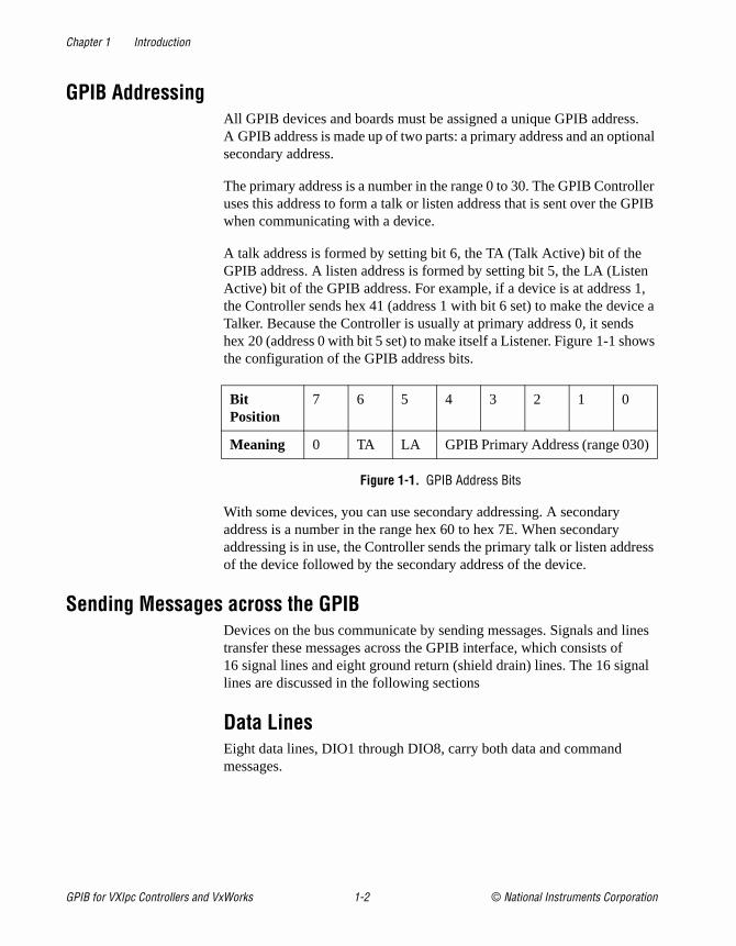
A talk address is formed by setting bit 6, the TA (Talk Active) bit of theGPIB address. A listen address is formed by setting bit 5, the LA (ListeActive) bit of the GPIB address. For example, if a device is at addressthe Controller sends hex 41 (address 1 with bit 6 set) to make the devTalker. Because the Controller is usually at primary address 0, it sendhex 20 (address 0 with bit 5 set) to make itself a Listener. Figure 1-1 shthe configuration of the GPIB address bits.
Figure 1-1. GPIB Address Bits
With some devices, you can use secondary addressing. A secondary address is a number in the range hex 60 to hex 7E. When secondary addressing is in use, the Controller sends the primary talk or listen addof the device followed by the secondary address of the device.
Sending Messages across the GPIBDevices on the bus communicate by sending messages. Signals and transfer these messages across the GPIB interface, which consists of16 signal lines and eight ground return (shield drain) lines. The 16 signlines are discussed in the following sections
Data LinesEight data lines, DIO1 through DIO8, carry both data and command messages.
Bit Position
7 6 5 4 3 2 1 0
Meaning 0 TA LA GPIB Primary Address (range 030)
GPIB for VXIpc Controllers and VxWorks 1-2 © National Instruments Corporation
Chapter 1 Introduction
of ked bytes
us.
l
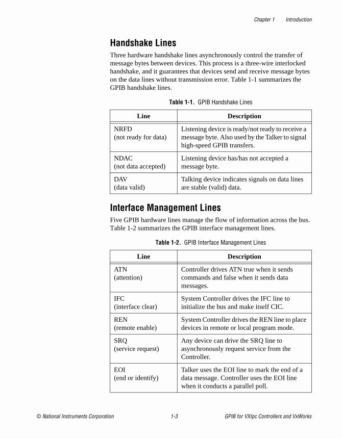
Handshake LinesThree hardware handshake lines asynchronously control the transfer message bytes between devices. This process is a three-wire interlochandshake, and it guarantees that devices send and receive messageon the data lines without transmission error. Table 1-1 summarizes theGPIB handshake lines.
Interface Management LinesFive GPIB hardware lines manage the flow of information across the bTable 1-2 summarizes the GPIB interface management lines.
Table 1-1. GPIB Handshake Lines
Line Description
NRFD (not ready for data)
Listening device is ready/not ready to receive amessage byte. Also used by the Talker to signahigh-speed GPIB transfers.
NDAC (not data accepted)
Listening device has/has not accepted a message byte.
DAV (data valid)
Talking device indicates signals on data lines are stable (valid) data.
Table 1-2. GPIB Interface Management Lines
Line Description
ATN (attention)
Controller drives ATN true when it sends commands and false when it sends data messages.
IFC (interface clear)
System Controller drives the IFC line to initialize the bus and make itself CIC.
REN (remote enable)
System Controller drives the REN line to placedevices in remote or local program mode.
SRQ (service request)
Any device can drive the SRQ line to asynchronously request service from the Controller.
EOI (end or identify)
Talker uses the EOI line to mark the end of a data message. Controller uses the EOI line when it conducts a parallel poll.
© National Instruments Corporation 1-3 GPIB for VXIpc Controllers and VxWorks
Chapter 1 Introduction
r at on,
ess
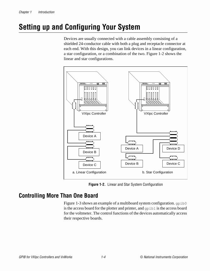
Setting up and Configuring Your SystemDevices are usually connected with a cable assembly consisting of a shielded 24-conductor cable with both a plug and receptacle connectoeach end. With this design, you can link devices in a linear configuratia star configuration, or a combination of the two. Figure 1-2 shows thelinear and star configurations.
Figure 1-2. Linear and Star System Configuration
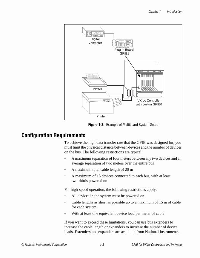
Controlling More Than One BoardFigure 1-3 shows an example of a multiboard system configuration. gpib0 is the access board for the plotter and printer, and gpib1 is the access boardfor the voltmeter. The control functions of the devices automatically acctheir respective boards.
Device A
Device B
Device C
Device DDevice A
Device CDevice B
a. Linear Configuration b. Star Configuration
VXIpc Controller VXIpc Controller
GPIB for VXIpc Controllers and VxWorks 1-4 © National Instruments Corporation
Chapter 1 Introduction
you ices
d an
ble
ice nts.
Figure 1-3. Example of Multiboard System Setup
Configuration RequirementsTo achieve the high data transfer rate that the GPIB was designed for,must limit the physical distance between devices and the number of devon the bus. The following restrictions are typical:
• A maximum separation of four meters between any two devices anaverage separation of two meters over the entire bus
• A maximum total cable length of 20 m
• A maximum of 15 devices connected to each bus, with at least two-thirds powered on
For high-speed operation, the following restrictions apply:
• All devices in the system must be powered on
• Cable lengths as short as possible up to a maximum of 15 m of cafor each system
• With at least one equivalent device load per meter of cable
If you want to exceed these limitations, you can use bus extenders to increase the cable length or expanders to increase the number of devloads. Extenders and expanders are available from National Instrume
Plotter
Printer
DigitalVoltmeter
VXIpc Controllerwith built-in GPIB0
Plug-in Board GPIB1
© National Instruments Corporation 1-5 GPIB for VXIpc Controllers and VxWorks
© National Instruments Corporation 2-1 GPIB for VXIpc Control
2
toe ed
ives ms 88
r e
tems ers r.
s,
der
:
Developing Your Application with the VxWorks Drivers
This chapter explains how to use the VxWorks GPIB drivers, and howdevelop a GPIB application using the NI-488 API.
Using the VxWorks NI-488 and ESP-488 DriversThe GPIB drivers that come with the VxWorks-based controller providtwo different ways to use the GPIB functions. The NI-488 driver is derivfrom the NI-488DDK, and offers a 100% compatible subset of the full NI-488 drivers used on other operating systems. The ESP-488 driver gusers of the VXIcpu-030 an easy way to port their existing GPIB prograto newer hardware by providing a mapping of ESP-488 functions to NI-4functions.
National Instruments strongly recommends you use the ESP-488 driveonly for porting applications from the VXIcpu-030 to a new controller. ThESP-488 driver is merely a mapping of the corresponding NI-488 functions, and using the actual NI-488 functions will make it easier to transfer programs between a VxWorks system and other operating systhat use the standard NI-488 driver. Furthermore, the NI-488 driver offsupport for multithreading, which is not available in the ESP-488 driveWe wish to emphasize that the ESP-488 library is provided only for theconvenience of users making the transition from the VXIcpu-030 to a newer controller.
Users of the VXIcpu-030 should note that under certain error conditionthe new ESP-488 library might behave slightly differently from the ESP-488 library provided with the VXIcpu-030. This is because of the underlying NI-488 driver, but should not adversely affect user code unnormal circumstances.
The GPIB library files provided with the VxWorks-based controller are
• nigpib.o —the NI-488 library
• espgpib.o —the ESP-488 library
lers and VxWorks
Chapter 2 Developing Your Application with the VxWorks Drivers
to rving ch
s:
• ibic.o —the old VXIcpu-030 GPIB interactive control program, which requires the ESP-488 library
• ugpib.h —the header file for the NI-488 API
• esp488.h —the header file for the ESP-488 API (refer to Compiling and Linking Your Application, later in this chapter, for more information about how to use this file)
• ni4882.c —source code for the 488.2 extensions library (in util subdirectory)
• ni4882.h —the header file for 488.2 extensions (in util subdirectory)
• README.TXT—a text file with further important information about theGPIB libraries
Using VxWorks NI-488 FunctionsThe VxWorks NI-488 functions perform basic GPIB operations. Theselow-level functions access the interface board directly and require youhandle the addressing and bus management protocol. In addition to seas a foundation upon which you can implement higher-level functions,these functions give you the flexibility and control to handle situations suas the following:
• Communicating with non-compliant (non-IEEE 488.2) devices
• Altering various low-level board configurations
• Developing non-controller applications
• Managing the bus in non-typical ways
The VxWorks NI-488 functions are completely compatible with the corresponding functions of standard NI-488.2 drivers from National Instruments.
Items to Include in Your ApplicationItems you should include in your C application programs are as follow
• The header file ugpib.h contains prototypes for the GPIB functionsand constants that you can use in your application.
• One or more calls to the ibfind function to obtain a unit descriptor for each GPIB board that the application uses.
• Code to check for errors after each NI-488 function call.
GPIB for VXIpc Controllers and VxWorks 2-2 © National Instruments Corporation
Chapter 2 Developing Your Application with the VxWorks Drivers
ne
s of tus
f ach les
lue
for
n ect.
e bit s,
• A function to handle GPIB errors. This function takes the board offliand closes the application. If the function is declared as:
void gpiberr (char * msg); /*function prototype*/
then your application invokes it as follows:
if (ibsta & ERR) {
gpiberr("GPIB error");
}
Checking Status with Global VariablesEach NI-488 function updates four global variables to reflect the statuthe board that you are using. These global status variables are the staword (ibsta ), the error variable (iberr ) and the count variables (ibcnt and ibcntl ). They contain useful information about the performance oyour application. Your application should check these variables after eGPIB call. The following sections describe each of these global variaband how you can use them in your application.
Status Word (ibsta)All functions update a global status word, ibsta , which contains information about the state of the GPIB and the GPIB hardware. The vastored in ibsta is the return value of all of the NI-488 functions except ibfind . You can examine various status bits in ibsta and use that information to make decisions about continued processing. If you checkpossible errors after each call using the ibsta ERR bit, debugging your application is much easier.
ibsta is an integer-sized value. The least significant 16 bits of ibsta are meaningful. A bit value of one (1) indicates that a certain condition is ieffect, and a bit value of zero (0) indicates that the condition is not in eff
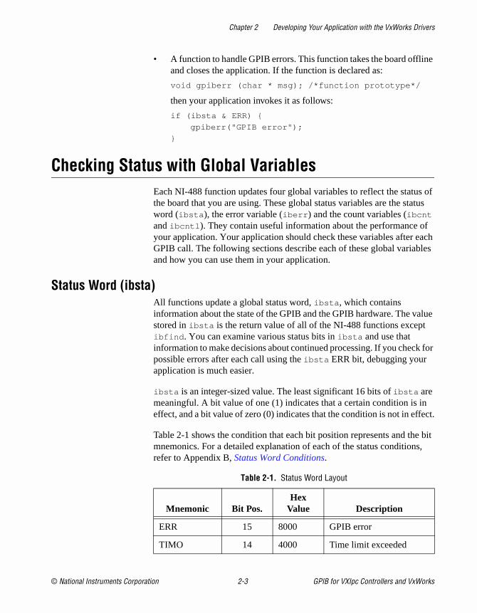
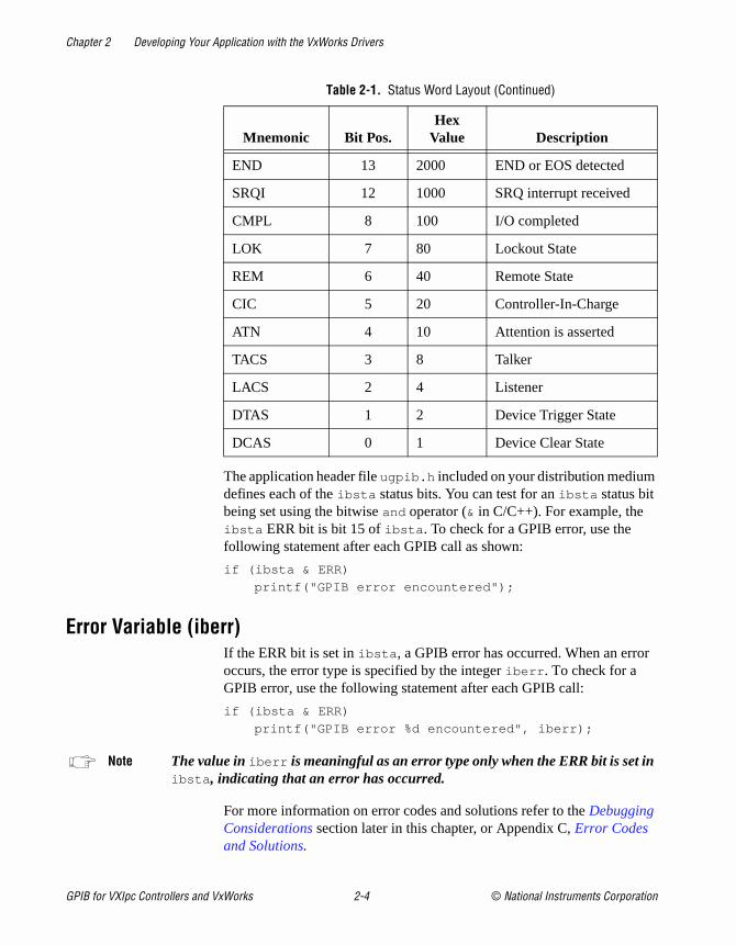
Table 2-1 shows the condition that each bit position represents and thmnemonics. For a detailed explanation of each of the status conditionrefer to Appendix B, Status Word Conditions.
Table 2-1. Status Word Layout
Mnemonic Bit Pos.Hex
Value Description
ERR 15 8000 GPIB error
TIMO 14 4000 Time limit exceeded
© National Instruments Corporation 2-3 GPIB for VXIpc Controllers and VxWorks
Chapter 2 Developing Your Application with the VxWorks Drivers
r
The application header file ugpib.h included on your distribution mediumdefines each of the ibsta status bits. You can test for an ibsta status bit being set using the bitwise and operator (& in C/C++). For example, the ibsta ERR bit is bit 15 of ibsta . To check for a GPIB error, use the following statement after each GPIB call as shown:
if (ibsta & ERR)
printf("GPIB error encountered");
Error Variable (iberr)If the ERR bit is set in ibsta , a GPIB error has occurred. When an errooccurs, the error type is specified by the integer iberr . To check for a GPIB error, use the following statement after each GPIB call:
if (ibsta & ERR)
printf("GPIB error %d encountered", iberr);
Note The value in iberr is meaningful as an error type only when the ERR bit is set inibsta , indicating that an error has occurred.
For more information on error codes and solutions refer to the Debugging Considerations section later in this chapter, or Appendix C, Error Codes and Solutions.
END 13 2000 END or EOS detected
SRQI 12 1000 SRQ interrupt received
CMPL 8 100 I/O completed
LOK 7 80 Lockout State
REM 6 40 Remote State
CIC 5 20 Controller-In-Charge
ATN 4 10 Attention is asserted
TACS 3 8 Talker
LACS 2 4 Listener
DTAS 1 2 Device Trigger State
DCAS 0 1 Device Clear State
Table 2-1. Status Word Layout (Continued)
Mnemonic Bit Pos.Hex
Value Description
GPIB for VXIpc Controllers and VxWorks 2-4 © National Instruments Corporation

Chapter 2 Developing Your Application with the VxWorks Drivers
d. If ber
n is
88
Count Variables (ibcnt and ibcntl)The count variables are updated after each read, write, or command function. ibcnt is an integer value and ibcntl is a long integer value. As implemented on most modern systems today, ibcnt and ibcntl are both 32-bit integers. On some older systems, such as MS-DOS, ibcnt is a 16-bit integer; on some newer systems, ibcntl is a 64-bit integer. For cross-platform compatibility, all applications should use ibcntl . If you are reading data, the count variables indicate the number of bytes reayou are sending data or commands, the count variables reflect the numof bytes sent.
In your application you can use the count variables to null-terminate aASCII string of data received from an instrument. For example, if datareceived in an array of characters, you can use ibcntl to null-terminate the array and print the measurement on the screen as follows:
char rdbuf[512];
ibrd (ud, rdbuf, 20L);
if (!(ibsta & ERR)){
rdbuf[ibcntl] = '\0';
printf ("Read: %s\n", rdbuf);
}
else {
error();
}
Compiling and Linking Your ApplicationWhen writing NI-488 or ESP-488 programs, you need to include the appropriate header file, which depends on which GPIB library you areusing. Normally, you will use NI-488, and the default setup uses the NI-4version of ugpib.h . If you need the ESP-488 API instead, rename the default ugpib.h to ni488.h and copy the file esp488.h to ugpib.h . Always use the directive #include “ugpib.h” in your programs, whether they are NI-488 or ESP-488 based.
Compiling a program for either API works no differently from compilingother programs for VxWorks. If you are unfamiliar with VxWorks, the process is very similar to compilation on other systems. You can find detailed information in the Wind River Systems programming documentation. You may find the Intel x86 appendix of the VxWorks Programmer’s Guide and the gcc/g++ chapter of the GNU Toolkit User’s Guide particularly helpful.
© National Instruments Corporation 2-5 GPIB for VXIpc Controllers and VxWorks

Chapter 2 Developing Your Application with the VxWorks Drivers
y is o es
ts
uld
ut for
ng
r. ring , you
On VxWorks, the functions in the NI-488 (or ESP-488) library are automatically linked into your program as long as the appropriate libraralready loaded when you load your NI-488 or ESP-488 application intVxWorks. To load the library, change to the directory in which the librariare installed (by default, /ide0 ) and use the command ld < nigpib.o or ld < espgpib.o .
Refer to the README.TXT file for more information about the two libraries. As noted at the beginning of this chapter, National Instrumenstrongly recommends you use the NI-488 driver unless you need the ESP-488 driver for backward compatibility with the VXIcpu-030.
Debugging ConsiderationsThis section contains typical errors you may encounter and some considerations for debugging your application.
Using the Global Status VariablesAfter each function call to your NI-488 driver, ibsta , iberr , ibcnt , and ibcntl are updated before the call returns to your application. You shocheck for an error after each GPIB call. Refer to the Checking Status with Global Variables section earlier in this chapter for more information abohow to use these variables within your program to automatically checkerrors.
After you determine which GPIB call is failing and note the correspondivalues of the global variables, refer to Appendix B, Status Word Conditions, and Appendix C, Error Codes and Solutions. These appendices can help you interpret the state of the driver.
Configuration ErrorsSome applications require customized configuration of the GPIB driveFor example, you might want to terminate reads on a special end-of-stcharacter, or you might require secondary addressing. In these casescan temporarily reconfigure the driver while your application is runningusing the ibeos and ibsad functions.
Refer to the descriptions of these functions and others in Chapter 3, NI-488 Functions, for more information.
GPIB for VXIpc Controllers and VxWorks 2-6 © National Instruments Corporation
Chapter 2 Developing Your Application with the VxWorks Drivers
488
the t for and o this our elf ght
rent ir IB
y s on ice end s
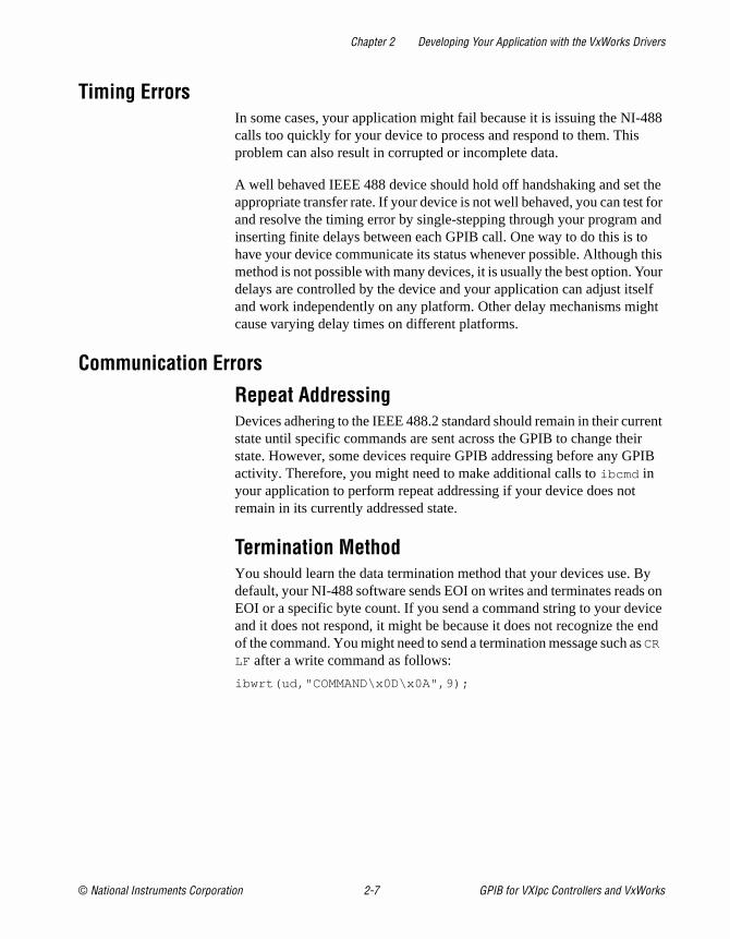
Timing ErrorsIn some cases, your application might fail because it is issuing the NI-calls too quickly for your device to process and respond to them. Thisproblem can also result in corrupted or incomplete data.
A well behaved IEEE 488 device should hold off handshaking and setappropriate transfer rate. If your device is not well behaved, you can tesand resolve the timing error by single-stepping through your program inserting finite delays between each GPIB call. One way to do this is thave your device communicate its status whenever possible. Althoughmethod is not possible with many devices, it is usually the best option. Ydelays are controlled by the device and your application can adjust itsand work independently on any platform. Other delay mechanisms micause varying delay times on different platforms.
Communication Errors
Repeat AddressingDevices adhering to the IEEE 488.2 standard should remain in their curstate until specific commands are sent across the GPIB to change thestate. However, some devices require GPIB addressing before any GPactivity. Therefore, you might need to make additional calls to ibcmd in your application to perform repeat addressing if your device does not remain in its currently addressed state.
Termination MethodYou should learn the data termination method that your devices use. Bdefault, your NI-488 software sends EOI on writes and terminates readEOI or a specific byte count. If you send a command string to your devand it does not respond, it might be because it does not recognize theof the command. You might need to send a termination message such aCR
LF after a write command as follows:
ibwrt(ud,"COMMAND\x0D\x0A",9);
© National Instruments Corporation 2-7 GPIB for VXIpc Controllers and VxWorks

© National Instruments Corporation 3-1 GPIB for VXIpc Control
3
tputge.
more
NI-488 Functions
This chapter lists the NI-488 functions and describes the purpose, format, input and ouparameters, and possible errors for each function.
Function NamesThe functions in this chapter are listed alphabetically.
PurposeEach function description includes a brief statement of the purpose of the function.
FormatThe format section describes the format of each function in the C programming langua
Input and OutputThe input and output parameters for each function are listed. Function Return describes the return value of the function.
DescriptionThe description section gives details about the purpose and effect of each function.
ExamplesSome function descriptions include sample code showing how to use the function. Fordetailed and complete examples, refer to the source code support files included in the util directory with your VxWorks GPIB software.
lers and VxWorks

Chapter 3 NI-488 Functions — Possible Errors
nd
Possible ErrorsEach function description includes a list of errors that could occur when it is invoked.
List of NI-488 FunctionsThe following table contains an alphabetical list of the VxWorks NI-488 functions.
Table 3-1. NI-488 Functions
Function Purpose
ibcac Become Active Controller
ibcmd Send GPIB commands
ibeos Configure the end-of-string (EOS) termination mode or character
ibeot Enable or disable the automatic assertion of the GPIB EOI line at the eof write I/O operations
ibfind Open and initialize a GPIB board
ibgts Go from Active Controller to Standby
ibist Set or clear the board individual status bit for parallel polls
iblines Return the status of the eight GPIB control lines
ibln Check for the presence of a device on the bus
ibloc Go to local
ibonl Place the interface board online or offline
ibpad Change the primary address
ibppc Parallel poll configure
ibrd Read data into a user buffer
ibrpp Conduct a parallel poll
ibrsc Request or release system control
ibrsv Request service and change the serial poll status byte
ibsad Change or disable the secondary address
ibsic Assert interface clear
GPIB for VXIpc Controllers and VxWorks 3-2 © National Instruments Corporation

Chapter 3 NI-488 Functions — List of NI-488 Functions
ibsre Set or clear the Remote Enable (REN) line
ibtmo Change or disable the I/O timeout period
ibwait Wait for GPIB events
ibwrt Write data from a user buffer
Table 3-1. NI-488 Functions (Continued)
Function Purpose
© National Instruments Corporation 3-3 GPIB for VXIpc Controllers and VxWorks

Chapter 3 NI-488 Functions — IBCAC
ut sly.
d for
h
IBCAC
PurposeBecome Active Controller.
Formatint ibcac (int ud, int v)
Inputud A board unit descriptorv Determines if control is to be taken asynchronously or
synchronously
OutputFunction Return The value of ibsta
DescriptionUsing ibcac , the designated GPIB board attempts to become the Active Controller by asserting ATN. If v is zero, the GPIB board takes control asynchronously; if v is non-zero, the GPIB board takes control synchronously. Before you call ibcac , the GPIB board must already be CIC. To make the board CIC, use the ibsic function.
To take control synchronously, the GPIB board attempts to assert the ATN signal withocorrupting transferred data. If this is not possible, the board takes control asynchronou
To take control asynchronously, the GPIB board asserts ATN immediately without regarany data transfer currently in progress.
Most applications do not need to use ibcac . Functions that require ATN to be asserted, sucas ibcmd , do so automatically.
Possible ErrorsEARG ud is valid but does not refer to an interface board.ECIC The interface board is not Controller-In-Charge.EDVR Either ud is invalid or the NI-488 driver is not installed.ENEB The interface board is not installed or is not properly configured.
GPIB for VXIpc Controllers and VxWorks 3-4 © National Instruments Corporation
Chapter 3 NI-488 Functions — IBCMD
le,
or talk.
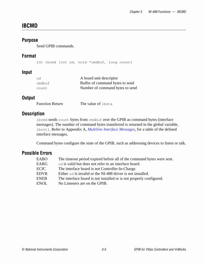
IBCMD
PurposeSend GPIB commands.
Formatint ibcmd (int ud, void *cmdbuf, long count)
Inputud A board unit descriptorcmdbuf Buffer of command bytes to sendcount Number of command bytes to send
OutputFunction Return The value of ibsta
Descriptionibcmd sends count bytes from cmdbuf over the GPIB as command bytes (interface messages). The number of command bytes transferred is returned in the global variabibcntl . Refer to Appendix A, Multiline Interface Messages, for a table of the defined interface messages.
Command bytes configure the state of the GPIB, such as addressing devices to listen
Possible ErrorsEABO The timeout period expired before all of the command bytes were sent.EARG ud is valid but does not refer to an interface board.ECIC The interface board is not Controller-In-Charge.EDVR Either ud is invalid or the NI-488 driver is not installed.ENEB The interface board is not installed or is not properly configured.ENOL No Listeners are on the GPIB.
© National Instruments Corporation 3-5 GPIB for VXIpc Controllers and VxWorks
Chapter 3 NI-488 Functions — IBEOS
meter
yte
at t
IBEOS
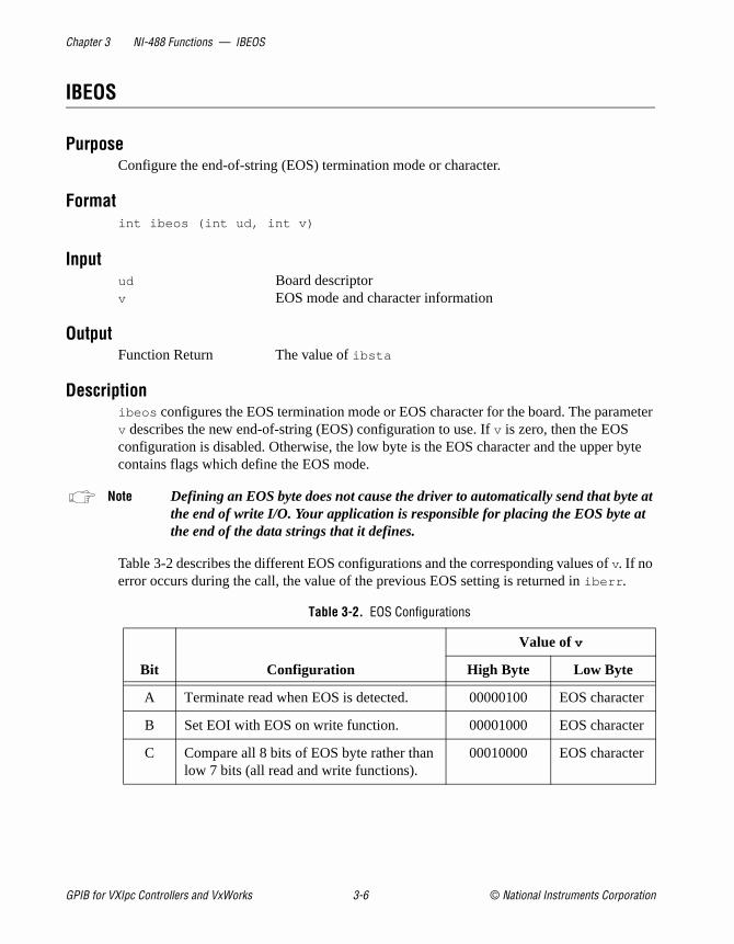
PurposeConfigure the end-of-string (EOS) termination mode or character.
Formatint ibeos (int ud, int v)
Inputud Board descriptorv EOS mode and character information
OutputFunction Return The value of ibsta
Descriptionibeos configures the EOS termination mode or EOS character for the board. The parav describes the new end-of-string (EOS) configuration to use. If v is zero, then the EOS configuration is disabled. Otherwise, the low byte is the EOS character and the upper bcontains flags which define the EOS mode.
Note Defining an EOS byte does not cause the driver to automatically send that bytethe end of write I/O. Your application is responsible for placing the EOS byte athe end of the data strings that it defines.
Table 3-2 describes the different EOS configurations and the corresponding values of v. If no error occurs during the call, the value of the previous EOS setting is returned in iberr .
Table 3-2. EOS Configurations
Bit Configuration
Value of v
High Byte Low Byte
A Terminate read when EOS is detected. 00000100 EOS character
B Set EOI with EOS on write function. 00001000 EOS character
C Compare all 8 bits of EOS byte rather than low 7 bits (all read and write functions).
00010000 EOS character
GPIB for VXIpc Controllers and VxWorks 3-6 © National Instruments Corporation

Chapter 3 NI-488 Functions — IBEOS
et EOS atches
line. s the when
Configuration bits A and C determine how to terminate read I/O operations. If bit A is sand bit C is clear, then a read ends when a byte that matches the low seven bits of thecharacter is received. If bits A and C are both set, then a read ends when a byte that mall eight bits of the EOS character is received.
Configuration bits B and C determine when a write I/O operation asserts the GPIB EOIIf bit B is set and bit C is clear, then EOI is asserted when the written character matchelow seven bits of the EOS character. If bits B and C are both set, then EOI is asserted the written character matches all eight bits of the EOS character.
For more information on the termination of I/O operations, refer to Chapter 4, GPIB Programming Techniques.
Examplesibeos (ud, 0x140A); /* Configure the software to end reads on
newline character (hex 0A) for the unit
descriptor, ud */
ibeos (ud, 0x180A); /* Configure the software to assert the GPIB
EOI line whenever the newline character
(hex 0A) is written out by the unit
descriptor, ud */
Possible ErrorsEARG The high byte of v contains invalid bits.EDVR Either ud is invalid or the NI-488 driver is not installed.ENEB The interface board is not installed or is not properly configured.
© National Instruments Corporation 3-7 GPIB for VXIpc Controllers and VxWorks

Chapter 3 NI-488 Functions — IBEOT
s for IB rs
IBEOT
PurposeEnable or disable the automatic assertion of the GPIB EOI line at the end of write I/O operations.
Formatint ibeot (int ud, int v)
Inputud Board descriptorv Enables or disables the end of transmission assertion of EOI
OutputFunction Return The value of ibsta
Descriptionibeot enables or disables the assertion of the EOI line at the end of write I/O operationthe board ud describes. If v is non-zero, then EOI is asserted when the last byte of a GPwrite is sent. If v is zero, then nothing occurs when the last byte is sent. If no error occuduring the call, then the previous value of EOT is returned in iberr .
For more information on the termination of I/O operations, refer to Chapter 4, GPIB Programming Techniques.
Possible ErrorsEDVR Either ud is invalid or the NI-488 driver is not installed.ENEB The interface board is not installed or is not properly configured.
GPIB for VXIpc Controllers and VxWorks 3-8 © National Instruments Corporation

Chapter 3 NI-488 Functions — IBFIND
t
IBFIND
PurposeOpen and initialize a GPIB board descriptor.
Formatint ibfind (char *udname)
Inputudname A GPIB board name
OutputFunction Return The board descriptor, or -1
Descriptionibfind acquires a descriptor for a GPIB board; this board descriptor can be used in subsequent NI-488 functions.
ibfind performs the equivalent of an ibonl 1 to initialize the board descriptor. The unit descriptor that ibfind returns remains valid until you use ibonl 0 to put the board offline.
If ibfind is unable to get a valid descriptor, -1 is returned; the ERR bit is set in ibsta and iberr contains EDVR.
Possible ErrorsEDVR Either udname is not recognized as a board name or the NI-488 driver is no
installed.ENEB The interface board is not installed or is not properly configured.
© National Instruments Corporation 3-9 GPIB for VXIpc Controllers and VxWorks

Chapter 3 NI-488 Functions — IBGTS
e until
f END ff state r
987,
IBGTS
PurposeGo from Active Controller to Standby.
Formatint ibgts (int ud, int v)
Inputud Board descriptorv Determines whether to perform acceptor handshaking
OutputFunction Return The value of ibsta
Descriptionibgts causes the GPIB board at ud to go to Standby Controller and the GPIB ATN line to bunasserted. If v is non-zero, acceptor handshaking or shadow handshaking is performedEND occurs or until ATN is reasserted by a subsequent ibcac call. With this option, the GPIB board can participate in data handshake as an acceptor without actually reading data. Iis detected, the interface board enters a Not Ready For Data (NRFD) handshake holdowhich results in hold off of subsequent GPIB transfers. If v is 0, no acceptor handshaking oholdoff is performed.
Before performing an ibgts with shadow handshake, call the ibeos function to establish proper EOS modes.
For details on the IEEE-488.1 handshake protocol, refer to ANSI/IEEE Standard 488.1-1IEEE Standard Digital Interface for Programmable Instrumentation.
Possible ErrorsEADR v is non-zero, and either ATN is low or the interface board is a Talker or
Listener.EARG ud is valid but does not refer to an interface board.ECIC The interface board is not Controller-In-Charge.EDVR Either ud is invalid or the NI-488 driver is not installed.ENEB The interface board is not installed or is not properly configured.
GPIB for VXIpc Controllers and VxWorks 3-10 © National Instruments Corporation
Chapter 3 NI-488 Functions — IBIST
IBIST
PurposeSet or clear the board individual status bit for parallel polls.
Formatint ibist (int ud, int v)
Inputud Board descriptorv Indicates whether to set or clear the ist bit
OutputFunction Return The value of ibsta
Descriptionibist sets the interface board ist (individual status) bit according to v. If v is zero, the ist bit is cleared; if v is non-zero, the ist bit is set. The previous value of the ist bit is returned in iberr .
For more information on parallel polling, refer to Chapter 4, GPIB Programming Techniques.
Possible ErrorsEARG ud is valid but does not refer to an interface board.EDVR Either ud is invalid or the NI-488 driver is not installed.ENEB The interface board is not installed or is not properly configured.
© National Instruments Corporation 3-11 GPIB for VXIpc Controllers and VxWorks
Chapter 3 NI-488 Functions — IBLINES
ard ns the
byte n the set
IBLINES
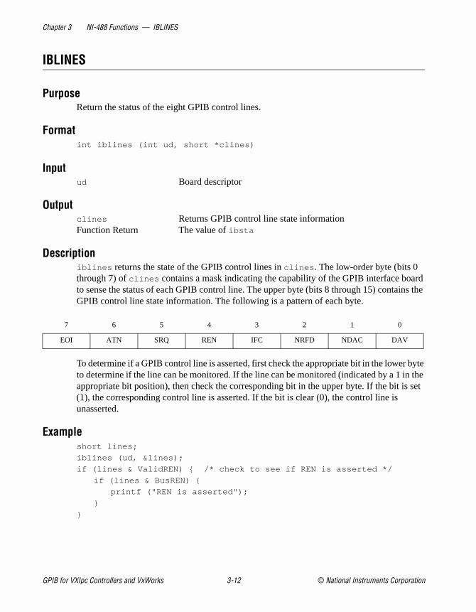
PurposeReturn the status of the eight GPIB control lines.
Formatint iblines (int ud, short *clines)
Inputud Board descriptor
Outputclines Returns GPIB control line state informationFunction Return The value of ibsta
Descriptioniblines returns the state of the GPIB control lines in clines . The low-order byte (bits 0 through 7) of clines contains a mask indicating the capability of the GPIB interface boto sense the status of each GPIB control line. The upper byte (bits 8 through 15) contaiGPIB control line state information. The following is a pattern of each byte.
To determine if a GPIB control line is asserted, first check the appropriate bit in the lowerto determine if the line can be monitored. If the line can be monitored (indicated by a 1 iappropriate bit position), then check the corresponding bit in the upper byte. If the bit is(1), the corresponding control line is asserted. If the bit is clear (0), the control line is unasserted.
Exampleshort lines;
iblines (ud, &lines);
if (lines & ValidREN) { /* check to see if REN is asserted */
if (lines & BusREN) {
printf ("REN is asserted");
}
}
7 6 5 4 3 2 1 0
EOI ATN SRQ REN IFC NRFD NDAC DAV
GPIB for VXIpc Controllers and VxWorks 3-12 © National Instruments Corporation

Chapter 3 NI-488 Functions — IBLINES
Possible ErrorsEARG ud is valid but does not refer to an interface board.EDVR Either ud is invalid or the NI-488 driver is not installed.ENEB The interface board is not installed or is not properly configured.
© National Instruments Corporation 3-13 GPIB for VXIpc Controllers and VxWorks
Chapter 3 NI-488 Functions — IBLN
y the
the is
IBLN
PurposeCheck for the presence of a device on the bus.
Formatint ibln (int ud, int pad, int sad, short *listen)
Inputud Board descriptorpad The primary GPIB address of the devicesad The secondary GPIB address of the device
Outputlisten Indicates if a device is present or notFunction Return The value of ibsta
Descriptionibln determines whether there is a listening device at the GPIB address designated bpad and sad parameters. If a Listener is detected, a non-zero value is returned in listen . If no Listener is found, zero is returned.
The pad parameter can be any valid primary address (a value between 0 and 30). Thesad parameter can be any valid secondary address (a value between 96 to 126), or one ofconstants NO_SAD or ALL_SAD. The constant NO_SAD designates that no secondary addressto be tested (only a primary address is tested). The constant ALL_SAD designates that all secondary addresses are to be tested.
Possible ErrorsEARG Either the pad or sad argument is invalid.ECIC The interface board is not Controller-In-Charge.EDVR Either ud is invalid or the NI-488 driver is not installed.ENEB The interface board is not installed or is not properly configured.
GPIB for VXIpc Controllers and VxWorks 3-14 © National Instruments Corporation

Chapter 3 NI-488 Functions — IBLOC
kout s
IBLOC
PurposeGo to Local.
Formatint ibloc (int ud)
Inputud Board descriptor
OutputFunction Return The value of ibsta
Descriptionibloc places the board in local mode if it is not in a lockout state. The board is in a locstate if LOK appears in the status word ibsta . If the board is in a lockout state, the call hano effect.
The ibloc function is used to simulate a front panel RTL (Return to Local) switch if thecomputer is used as an instrument.
Possible ErrorsEDVR Either ud is invalid or the NI-488 driver is not installed.ENEB The interface board is not installed or is not properly configured.
© National Instruments Corporation 3-15 GPIB for VXIpc Controllers and VxWorks

Chapter 3 NI-488 Functions — IBONL
IBONL
PurposePlace the interface board online or offline.
Formatint ibonl (int ud, int v)
Inputud Board descriptorv Indicates whether the board is to be taken online or offline
OutputFunction Return The value of ibsta
Descriptionibonl resets the board and places all its software configuration parameters in their pre-configured state. In addition, if v is zero, the interface board is taken offline. If v is non-zero, the interface board is left operational, or online.
If an interface board is taken offline, the board descriptor (ud) is no longer valid. You must execute an ibfind to access the board again.
Possible ErrorsEDVR Either ud is invalid or the NI-488 driver is not installed.ENEB The interface board is not installed or is not properly configured.
GPIB for VXIpc Controllers and VxWorks 3-16 © National Instruments Corporation
Chapter 3 NI-488 Functions — IBPAD
IBPAD
PurposeChange the primary address.
Formatint ibpad (int ud, int v)
Inputud Board descriptorv GPIB primary address
OutputFunction Return The value of ibsta
Descriptionibpad sets the primary GPIB address of the board to v, an integer ranging from 0 to 30. If noerror occurs during the call, then iberr contains the previous GPIB primary address.
Possible ErrorsEARG v is not a valid primary GPIB address; it must be in the range 0 to 30.EDVR Either ud is invalid or the NI-488 driver is not installed.ENEB The interface board is not installed or is not properly configured.
© National Instruments Corporation 3-17 GPIB for VXIpc Controllers and VxWorks

Chapter 3 NI-488 Functions — IBPPC
llel or
IBPPC
PurposeParallel poll configure.
Formatint ibppc (int ud, int v)
Inputud Board descriptorv Parallel poll enable/disable value
OutputFunction Return The value of ibsta
Descriptionibppc performs a local parallel poll configuration on the interface board using the parapoll configuration value v. Valid parallel poll messages are 96 to 126 (hex 60 to hex 7E) zero to send PPD. If no error occurs during the call, then iberr contains the previous valueof the local parallel poll configuration.
For more information on parallel polling, refer to Chapter 4, GPIB Programming Techniques.
Possible ErrorsEARG v does not contain a valid PPE or PPD message.EDVR Either ud is invalid or the NI-488 driver is not installed.ENEB The interface board is not installed or is not properly configured.
GPIB for VXIpc Controllers and VxWorks 3-18 © National Instruments Corporation

Chapter 3 NI-488 Functions — IBRD
ates is erred
IBRD
PurposeRead data into a user buffer.
Formatint ibrd (int ud, void *rdbuf, long count)
Inputud Board descriptorcount Number of bytes to be read from the GPIB
Outputrdbuf Address of buffer into which data is readFunction Return The value of ibsta
Descriptionibrd reads up to count bytes of data and places the data into the buffer specified by rdbuf . ibrd assumes that the GPIB is already properly addressed. The operation terminates normally when count bytes have been received or END is received. The operation terminwith an error if the transfer could not complete within the timeout period or, if the boardnot CIC, the CIC sends a Device clear on the GPIB. The actual number of bytes transfis returned in the global variable ibcntl .
Possible ErrorsEABO Either count bytes or END was not received within the timeout period or a
Device Clear message was received after the read operation began.EADR The GPIB is not correctly addressed; use ibcmd to address the GPIB.EDVR Either ud is invalid or the NI-488 driver is not installed.ENEB The interface board is not installed or is not properly configured.
© National Instruments Corporation 3-19 GPIB for VXIpc Controllers and VxWorks

Chapter 3 NI-488 Functions — IBRPP
IBRPP
PurposeConduct a parallel poll.
Formatint ibrpp (int ud, char *ppr)
Inputud Board descriptor
Outputppr Parallel poll response byteFunction Return The value of ibsta
Descriptionibrpp parallel polls all the devices on the GPIB. The result of this poll is returned in ppr .
For more information on parallel polling, refer to Chapter 4, GPIB Programming Techniques.
Possible ErrorsECIC The interface board is not Controller-In-Charge.EDVR Either ud is invalid or the NI-488 driver is not installed.ENEB The interface board is not installed or is not properly configured.
GPIB for VXIpc Controllers and VxWorks 3-20 © National Instruments Corporation

Chapter 3 NI-488 Functions — IBRSC
able
IBRSC
PurposeRequest or release system control.
Formatint ibrsc (int ud, int v)
Inputud Board descriptorv Determines if system control is to be requested or released
OutputFunction Return The value of ibsta
Descriptionibrsc requests or releases the capability to send Interface Clear (IFC) and Remote En(REN) messages. If v is zero, the board releases system control, and functions requiringSystem Controller capability are not allowed. If v is non-zero, functions requiring System Controller capability are subsequently allowed. If no error occurs during the call, then iberr contains the previous System Controller state of the board.
Possible ErrorsEARG ud is a valid descriptor but does not refer to a board.EDVR Either ud is invalid or the NI-488 driver is not installed.ENEB The interface board is not installed or is not properly configured.
© National Instruments Corporation 3-21 GPIB for VXIpc Controllers and VxWorks
Chapter 3 NI-488 Functions — IBRSV
an
r,
IBRSV
PurposeRequest service and change the serial poll status byte.
Formatint ibrsv (int ud, int v)
Inputud Board descriptorv Serial poll status byte
OutputFunction Return The value of ibsta
Descriptionibrsv is used to request service from the Controller and to provide the Controller with application-dependent status byte when the Controller serial polls the GPIB board.
The value v is the status byte that the GPIB board returns when serial polled by the Controller-In-Charge. If bit 6 (hex 40) is set in v, the GPIB board requests service from theController by asserting the GPIB SRQ line. When ibrsv is called and an error does not occuthe previous status byte is returned in iberr .
Possible ErrorsEARG ud is a valid descriptor but does not refer to a board. EDVR Either ud is invalid or the NI-488 driver is not installed.ENEB The interface board is not installed or is not properly configured.
GPIB for VXIpc Controllers and VxWorks 3-22 © National Instruments Corporation

Chapter 3 NI-488 Functions — IBSAD
ror ed in
IBSAD
PurposeChange or disable the secondary address.
Formatint ibsad (int ud, int v)
Inputud Board descriptorv GPIB secondary address
OutputFunction Return The value of ibsta
Descriptionibsad changes the secondary GPIB address of the given board to v, an integer in the range 96 to 126 (hex 60 to hex 7E) or zero. If v is zero, secondary addressing is disabled. If no eroccurs during the call, then the previous value of the GPIB secondary address is returniberr .
Possible ErrorsEARG v is non-zero and outside the legal range 96 to 126.EDVR Either ud is invalid or the NI-488 driver is not installed.ENEB The interface board is not installed or is not properly configured.
© National Instruments Corporation 3-23 GPIB for VXIpc Controllers and VxWorks

Chapter 3 NI-488 Functions — IBSIC
tive
rnal ernal
IBSIC
PurposeAssert interface clear.
Formatint ibsic (int ud)
Inputud Board descriptor
OutputFunction Return The value of ibsta
Descriptionibsic asserts the GPIB interface clear (IFC) line for at least 100 µs if the GPIB board is System Controller. This initializes the GPIB and makes the interface board CIC and AcController with ATN asserted.
The IFC signal resets only the GPIB interface functions of bus devices and not the intedevice functions. Consult your device documentation to determine how to reset the intfunctions of your device.
Possible ErrorsEARG ud is a valid descriptor but does not refer to a board.EDVR Either ud is invalid or the NI-488 driver is not installed.ENEB The interface board is not installed or is not properly configured.ESAC The board does not have System Controller capability.
GPIB for VXIpc Controllers and VxWorks 3-24 © National Instruments Corporation

Chapter 3 NI-488 Functions — IBSRE
hould
IBSRE
PurposeSet or clear the Remote Enable line.
Formatint ibsre (int ud, int v)
Inputud Board descriptorv Indicates whether to set or clear the REN line
OutputFunction Return The value of ibsta
DescriptionIf v is non-zero, the GPIB Remote Enable (REN) line is asserted. If v is zero, REN is unasserted. The previous value of REN is returned in iberr .
Devices use REN to choose between local and remote modes of operation. A device snot actually enter remote mode until it receives its listen address.
Possible ErrorsEARG ud is a valid descriptor but does not refer to a board.EDVR Either ud is invalid or the NI-488 driver is not installed.ENEB The interface board is not installed or is not properly configured.ESAC The board does not have System Controller capability.
© National Instruments Corporation 3-25 GPIB for VXIpc Controllers and VxWorks

Chapter 3 NI-488 Functions — IBTMO
the
IBTMO
PurposeChange or disable the timeout period.
Formatint ibtmo (int ud, int v)
Inputud Board descriptorv Timeout duration code
OutputFunction Return The value of ibsta
Descriptionibtmo sets the timeout period of the board to v. The timeout period is used to select the maximum duration allowed for an I/O operation (for example, ibrd and ibwrt ) or for an ibwait operation with TIMO in the wait mask. If the operation does not complete beforetimeout period elapses, then the operation is aborted and TIMO is returned in ibsta . See Table 3-3 for a list of valid timeout values. These timeout values represent the minimumtimeout period. The actual period may be longer.
Table 3-3. Timeout Code Values
Constant Value of v Minimum Timeout
TNONE 0 disabled/no timeout
T10us 1 10
T30us 2 30
T100us 3 100
T300us 4 300
T1ms 5 1 ms
T3ms 6 3 ms
T10ms 7 10 ms
T30ms 8 30 ms
T100ms 9 100 ms
GPIB for VXIpc Controllers and VxWorks 3-26 © National Instruments Corporation

Chapter 3 NI-488 Functions — IBTMO
Possible ErrorsEARG v is invalid.EDVR Either ud is invalid or the NI-488 driver is not installed.ENEB The interface board is not installed or is not properly configured.
T300ms 10 300 ms
T1s 11 1 s
T3s 12 3 s
T10s 13 10 s
T30s 14 30 s
T100s 15 100 s
T300s 16 300 s
T1000s 17 1000 s
Table 3-3. Timeout Code Values (Continued)
Constant Value of v Minimum Timeout
© National Instruments Corporation 3-27 GPIB for VXIpc Controllers and VxWorks
Chapter 3 NI-488 Functions — IBWAIT
of
TIMO
IBWAIT
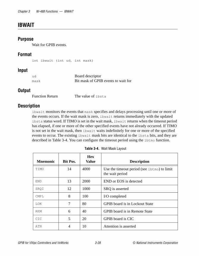
PurposeWait for GPIB events.
Formatint ibwait (int ud, int mask)
Inputud Board descriptormask Bit mask of GPIB events to wait for
OutputFunction Return The value of ibsta
Descriptionibwait monitors the events that mask specifies and delays processing until one or more the events occurs. If the wait mask is zero, ibwait returns immediately with the updated ibsta status word. If TIMO is set in the wait mask, ibwait returns when the timeout periodhas elapsed, if one or more of the other specified events have not already occurred. If is not set in the wait mask, then ibwait waits indefinitely for one or more of the specified events to occur. The existing ibwait mask bits are identical to the ibsta bits, and they are described in Table 3-4. You can configure the timeout period using the ibtmo function.
Table 3-4. Wait Mask Layout
Mnemonic Bit Pos.Hex
Value Description
TIMO 14 4000 Use the timeout period (see ibtmo ) to limit the wait period
END 13 2000 END or EOS is detected
SRQI 12 1000 SRQ is asserted
CMPL 8 100 I/O completed
LOK 7 80 GPIB board is in Lockout State
REM 6 40 GPIB board is in Remote State
CIC 5 20 GPIB board is CIC
ATN 4 10 Attention is asserted
GPIB for VXIpc Controllers and VxWorks 3-28 © National Instruments Corporation

Chapter 3 NI-488 Functions — IBWAIT
Possible ErrorsEARG The bit set in mask is invalid.EDVR Either ud is invalid or the NI-488 driver is not installed.ENEB The interface board is not installed or is not properly configured.
TACS 3 8 GPIB board is Talker
LACS 2 4 GPIB board is Listener
DTAS 1 2 GPIB board is in Device Trigger State
DCAS 0 1 GPIB board is in Device Clear State
Table 3-4. Wait Mask Layout (Continued)
Mnemonic Bit Pos.Hex
Value Description
© National Instruments Corporation 3-29 GPIB for VXIpc Controllers and VxWorks
Chapter 3 NI-488 Functions — IBWRT
PIB.
ar
IBWRT
PurposeWrite data from a user buffer.
Formatint ibwrt (int ud, void *wrtbuf, long count)
Inputud Board descriptorwrtbuf Address of the buffer containing the bytes to writecount Number of bytes to be written
OutputFunction Return The value of ibsta
Descriptionibwrt writes count bytes of data from the buffer specified by wrtbuf ; ibwrt assumes that the GPIB is already properly addressed. The operation terminates normally when count bytes have been sent. The operation terminates with an error if count bytes could not be sentwithin the timeout period or, if the board is not CIC, the CIC sends Device Clear on the GThe actual number of bytes transferred is returned in the global variable ibcntl .
Possible ErrorsEABO Either count bytes were not sent within the timeout period, or a Device Cle
message was received after the write operation began.EADR The GPIB is not correctly addressed; use ibcmd to address the GPIB.EDVR Either ud is invalid or the NI-488 driver is not installed.ENEB The interface board is not installed or is not properly configured.ENOL No Listeners were detected on the bus.
GPIB for VXIpc Controllers and VxWorks 3-30 © National Instruments Corporation
© National Instruments Corporation 4-1 GPIB for VXIpc Control
4
ourver ed.
on PIB
as of
ten
five
s the the
s e If
GPIB Programming Techniques
This chapter describes techniques for using some NI-488 functions in yapplication.
For more detailed information about each function, refer to Chapter 3,NI-488 Functions.
Termination of Data TransfersGPIB data transfers are terminated either when the GPIB EOI line is asserted with the last byte of a transfer or when a preconfigured end-of-string (EOS) character is transmitted. By default, the NI-488 driasserts EOI with the last byte of writes and the EOS modes are disabl
You can use the ibeot function to enable or disable the end of transmissi(EOT) mode. If EOT mode is enabled, the NI-488 driver asserts the GEOI line when the last byte of a write is sent out on the GPIB. If it is disabled, the EOI line is not asserted with the last byte of a write.
You can use the ibeos function to enable, disable, or configure the EOSmodes. EOS mode configuration includes the following information:
• A 7-bit or 8-bit EOS byte
• EOS comparison method—This indicates whether the EOS byte hseven or eight significant bits. For a 7-bit EOS byte, the eighth bit the EOS byte is ignored.
• EOS write method—If you enable this, the NI-488 driver automatically asserts the GPIB EOI line when the EOS byte is writto the GPIB. If the buffer passed into an ibwrt call contains five occurrences of the EOS byte, the EOI line is asserted as each of theEOS bytes are written to the GPIB. If an ibwrt buffer does not contain an occurrence of the EOS byte, the EOI line is not asserted (unlesEOT mode is enabled, in which case the EOI line is asserted withlast byte of the write).
• EOS read method—If you enable this, the NI-488 driver terminateibrd calls when the EOS byte is detected on the GPIB or when thGPIB EOI line is asserted or when the specified count is reached.
lers and VxWorks

Chapter 4 GPIB Programming Techniques
. If
ays
use are ot
ts set
ive ta to the
L or ion ate the f the
ted, ler ng
you disable the EOS read method, ibrd calls terminate only when theGPIB EOI line is asserted or the specified count has been read.
Waiting for GPIB ConditionsYou can use the ibwait function to obtain the current ibsta value or to suspend your application until a specified condition occurs on the GPIByou use ibwait with a parameter of zero, it immediately updates ibsta and returns. If you want to use ibwait to wait for one or more events to occur, then pass a wait mask to the function. The wait mask should alwinclude the TIMO event; otherwise, your application is suspended indefinitely until one of the wait mask events occurs.
Talker/Listener ApplicationsAlthough designed for Controller-In-Charge applications, you can also the NI-488 software in most non-Controller situations. These situationsknown as Talker/Listener applications because the interface board is nthe GPIB Controller.
A Talker/Listener application typically uses ibwait with a mask of 0 to monitor the status of the interface board. Then, based on the status biin ibsta , the application takes whatever action is appropriate. For example, the application could monitor the status bits TACS (Talker ActState) and LACS (Listener Active State) to determine when to send daor receive data from the Controller. The application could also monitor DCAS (Device Clear Active State) and DTAS (Device Trigger Active State) bits to determine if the Controller has sent the device clear (DCSDC) or trigger (GET) messages to the interface board. If the applicatdetects a device clear from the Controller, it might reset the internal stof message buffers. If it detects a trigger message from the Controller,application might begin an operation such as taking a voltage reading iapplication is actually acting as a voltmeter.
Serial PollingYou can use serial polling to obtain specific information from GPIB devices when they request service. When the GPIB SRQ line is asserit signals the Controller that a service request is pending. The Controlmust then determine which device asserted the SRQ line and respondaccordingly. The most common method for SRQ detection and servici
GPIB for VXIpc Controllers and VxWorks 4-2 © National Instruments Corporation

Chapter 4 GPIB Programming Techniques
tion
ng rial d
set rn a wer
e. In also bit a.
est,
when s.
nd e
or
is the serial poll. This section describes how you can set up your applicato detect and respond to service requests from GPIB devices.
Service Requests from IEEE 488 DevicesIEEE 488 devices request service from the GPIB Controller by assertithe GPIB SRQ line. When the Controller acknowledges the SRQ, it sepolls each open device on the bus to determine which device requesteservice. Any device requesting service returns a status byte with bit 6 and then unasserts the SRQ line. Devices not requesting service retustatus byte with bit 6 cleared. Manufacturers of IEEE 488 devices use loorder bits to communicate the reason for the service request or to summarize the state of the device.
Service Requests from IEEE 488.2 DevicesThe IEEE 488.2 standard refined the bit assignments in the status bytaddition to setting bit 6 when requesting service, IEEE 488.2 devices use two other bits to specify their status. Bit 4, the Message Available(MAV), is set when the device is ready to send previously queried datBit 5, the Event Status bit (ESB), is set if one or more of the enabled IEEE 488.2 events occurs. These events include power-on, user requcommand error, execution error, device dependent error, query error, request control, and operation complete. The device can assert SRQ ESB or MAV are set, or when a manufacturer-defined condition occur
SRQ and Serial Polling with NI-488 FunctionsThe 488.2 application library included with the NI-488 driver contains some high-level routines that you can use to conduct SRQ servicing aserial polling. Routines pertinent to SRQ servicing and serial polling arni4882_ReadStatusByte , ni4882_TestSRQ , and ni4882_WaitSRQ .
ni4882_ReadStatusByte serial polls a single device and returns its status byte.
ni4882_TestSRQ determines whether the SRQ line is asserted or unasserted, and returns to the caller immediately.
ni4882_WaitSRQ is similar to ni4882_TestSRQ , except that ni4882_WaitSRQ suspends the application until either SRQ is assertedthe timeout period is exceeded.
© National Instruments Corporation 4-3 GPIB for VXIpc Controllers and VxWorks
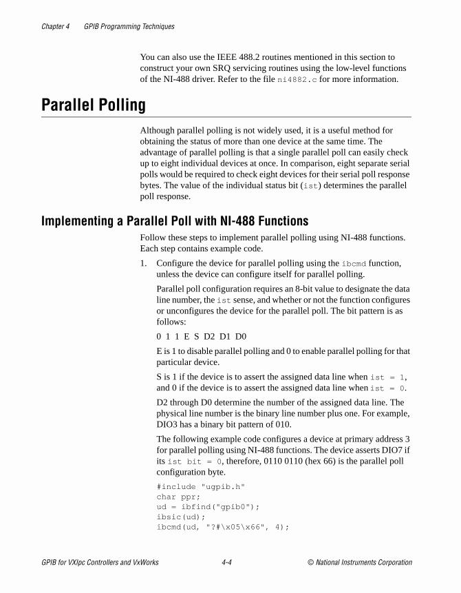
Chapter 4 GPIB Programming Techniques
s
ck erial nse
s.
ata es s
at
he le,
s 3 if
You can also use the IEEE 488.2 routines mentioned in this section toconstruct your own SRQ servicing routines using the low-level functionof the NI-488 driver. Refer to the file ni4882.c for more information.
Parallel PollingAlthough parallel polling is not widely used, it is a useful method for obtaining the status of more than one device at the same time. The advantage of parallel polling is that a single parallel poll can easily cheup to eight individual devices at once. In comparison, eight separate spolls would be required to check eight devices for their serial poll respobytes. The value of the individual status bit (ist ) determines the parallel poll response.
Implementing a Parallel Poll with NI-488 FunctionsFollow these steps to implement parallel polling using NI-488 functionEach step contains example code.
1. Configure the device for parallel polling using the ibcmd function, unless the device can configure itself for parallel polling.
Parallel poll configuration requires an 8-bit value to designate the dline number, the ist sense, and whether or not the function configuror unconfigures the device for the parallel poll. The bit pattern is afollows:
0 1 1 E S D2 D1 D0
E is 1 to disable parallel polling and 0 to enable parallel polling for thparticular device.
S is 1 if the device is to assert the assigned data line when ist = 1 , and 0 if the device is to assert the assigned data line when ist = 0 .
D2 through D0 determine the number of the assigned data line. Tphysical line number is the binary line number plus one. For exampDIO3 has a binary bit pattern of 010.
The following example code configures a device at primary addresfor parallel polling using NI-488 functions. The device asserts DIO7its ist bit = 0 , therefore, 0110 0110 (hex 66) is the parallel pollconfiguration byte.
#include "ugpib.h"char ppr;ud = ibfind("gpib0");ibsic(ud);ibcmd(ud, "?#\x05\x66", 4);
GPIB for VXIpc Controllers and VxWorks 4-4 © National Instruments Corporation
Chapter 4 GPIB Programming Techniques
as
ll 5. If
rn 70
If the GPIB interface board configures itself for a parallel poll, youshould use the ibppc function. Pass the board unit descriptor value the first argument in ibppc . In addition, if the individual status bit (ist ) of the board needs to be changed, use the ibist function.
In the following example, the GPIB board is to configure itself to participate in a parallel poll. It asserts DIO5 when ist = 1 if a parallel poll is conducted.
ibppc(ud, 0x6C);ibist(ud, 1);
2. Conduct the parallel poll using ibrpp and check the response for a certain value. The following example code performs the parallel poand compares the response to hex 10, which corresponds to DIOthat bit is set, the ist of the device is 1.
ibrpp(ud, &ppr);if (ppr & 0x10) printf("ist = 1\n");
3. Unconfigure the device for parallel polling with ibcmd . Notice that any value having the parallel poll disable bit set (bit 4) in the bit pattedisables the configuration, so you can use any value between hexand 7E.
ibcmd(ud,"?#\x05\x70", 4);
© National Instruments Corporation 4-5 GPIB for VXIpc Controllers and VxWorks
© National Instruments Corporation A-1 GPIB for VXIpc Control
A
hich ce ithMultiline Interface Messages
This appendix contains a multiline interface message reference list, wdescribes the mnemonics and messages that correspond to the interfafunctions. These multiline interface messages are sent and received wATN asserted.
For more information on these messages, refer to the ANSI/IEEE Standard 488.1-1987, IEEE Standard Digital Interface for ProgrammableInstrumentation.
lers and VxWorks
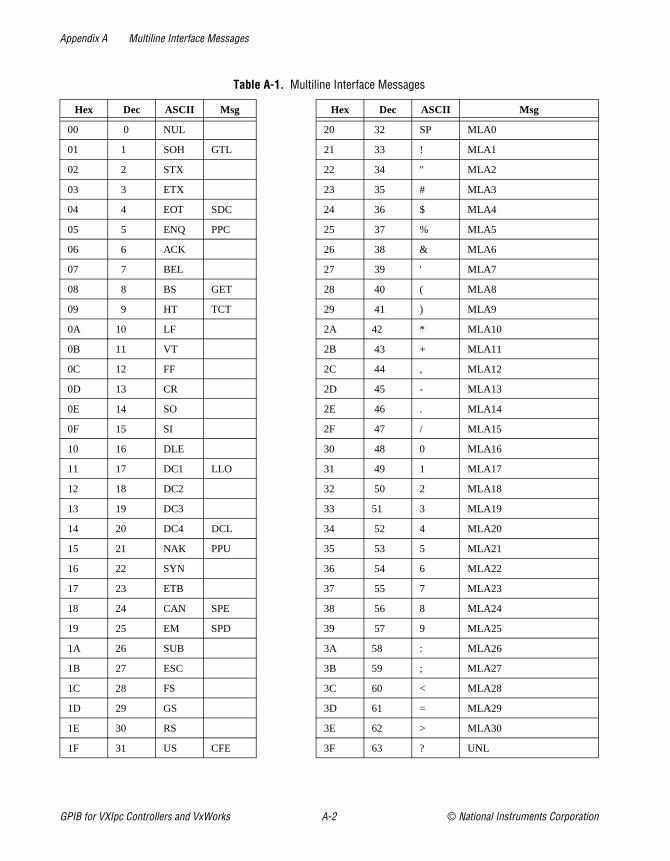
Appendix A Multiline Interface Messages
Table A-1. Multiline Interface Messages
Hex Dec ASCII Msg Hex Dec ASCII Msg
00 0 NUL 20 32 SP MLA0
01 1 SOH GTL 21 33 ! MLA1
02 2 STX 22 34 " MLA2
03 3 ETX 23 35 # MLA3
04 4 EOT SDC 24 36 $ MLA4
05 5 ENQ PPC 25 37 % MLA5
06 6 ACK 26 38 & MLA6
07 7 BEL 27 39 ' MLA7
08 8 BS GET 28 40 ( MLA8
09 9 HT TCT 29 41 ) MLA9
0A 10 LF 2A 42 * MLA10
0B 11 VT 2B 43 + MLA11
0C 12 FF 2C 44 , MLA12
0D 13 CR 2D 45 - MLA13
0E 14 SO 2E 46 . MLA14
0F 15 SI 2F 47 / MLA15
10 16 DLE 30 48 0 MLA16
11 17 DC1 LLO 31 49 1 MLA17
12 18 DC2 32 50 2 MLA18
13 19 DC3 33 51 3 MLA19
14 20 DC4 DCL 34 52 4 MLA20
15 21 NAK PPU 35 53 5 MLA21
16 22 SYN 36 54 6 MLA22
17 23 ETB 37 55 7 MLA23
18 24 CAN SPE 38 56 8 MLA24
19 25 EM SPD 39 57 9 MLA25
1A 26 SUB 3A 58 : MLA26
1B 27 ESC 3B 59 ; MLA27
1C 28 FS 3C 60 < MLA28
1D 29 GS 3D 61 = MLA29
1E 30 RS 3E 62 > MLA30
1F 31 US CFE 3F 63 ? UNL
GPIB for VXIpc Controllers and VxWorks A-2 © National Instruments Corporation

Appendix A Multiline Interface Messages
40 64 @ MTA0 60 96 ` MSA0, PPE
41 65 A MTA1 61 97 a MSA1, PPE, CFG1
42 66 B MTA2 62 98 b MSA2, PPE, CFG2
43 67 C MTA3 63 99 c MSA3, PPE, CFG3
44 68 D MTA4 64 100 d MSA4, PPE, CFG4
45 69 E MTA5 65 101 e MSA5, PPE, CFG5
46 70 F MTA6 66 102 f MSA6, PPE, CFG6
47 71 G MTA7 67 103 g MSA7, PPE, CFG7
48 72 H MTA8 68 104 h MSA8, PPE, CFG8
49 73 I MTA9 69 105 i MSA9, PPE, CFG9
4A 74 J MTA10 6A 106 j MSA10, PPE, CFG10
4B 75 K MTA11 6B 107 k MSA11, PPE, CFG11
4C 76 L MTA12 6C 108 l MSA12, PPE, CFG12
4D 77 M MTA13 6D 109 m MSA13, PPE, CFG13
4E 78 N MTA14 6E 110 n MSA14, PPE, CFG14
4F 79 O MTA15 6F 111 o MSA15, PPE, CFG15
50 80 P MTA16 70 112 p MSA16, PPD
51 81 Q MTA17 71 113 q MSA17, PPD
52 82 R MTA18 72 114 r MSA18, PPD
53 83 S MTA19 73 115 s MSA19, PPD
54 84 T MTA20 74 116 t MSA20, PPD
55 85 U MTA21 75 117 u MSA21, PPD
56 86 V MTA22 76 118 v MSA22, PPD
57 87 W MTA23 77 119 w MSA23, PPD
58 88 X MTA24 78 120 x MSA24, PPD
59 89 Y MTA25 79 121 y MSA25, PPD
5A 90 Z MTA26 7A 122 z MSA26, PPD
5B 91 [ MTA27 7B 123 { MSA27, PPD
5C 92 \ MTA28 7C 124 | MSA28, PPD
5D 93 ] MTA29 7D 125 } MSA29, PPD
5E 94 ^ MTA30 7E 126 ~ MSA30, PPD
5F 95 _ UNT 7F 127 DEL
Table A-1. Multiline Interface Messages (Continued)
Hex Dec ASCII Msg Hex Dec ASCII Msg
© National Instruments Corporation A-3 GPIB for VXIpc Controllers and VxWorks

Appendix A Multiline Interface Messages
speed
Multiline Interface Message Definitions
CFE † Configuration EnableCFG † ConfigureDCL Device ClearGET Group Execute TriggerGTL Go To LocalLLO Local LockoutMLA My Listen AddressMSA My Secondary AddressMTA My Talk AddressPPC Parallel Poll Configure
PPD Parallel Poll DisablePPE Parallel Poll EnablePPU Parallel Poll UnconfigureSDC Selected Device ClearSPD Serial Poll DisableSPE Serial Poll EnableTCT Take ControlUNL UnlistenUNT Untalk
†This multiline interface message is a proposed extension to the IEEE 488.1 specification to support the HS488 high-protocol.
GPIB for VXIpc Controllers and VxWorks A-4 © National Instruments Corporation

© National Instruments Corporation B-1 GPIB for VXIpc Control
B
Status Word Conditions
This appendix describes the conditions reported in the status word, ibsta .
For information about how to use ibsta in your application program, referto Chapter 2, Developing Your Application with the VxWorks Drivers.
Table B-1 shows the status word layout.
Table B-1. Status Word Layout
Mnemonic Bit Pos.Hex
Value Description
ERR 15 8000 GPIB error
TIMO 14 4000 Time limit exceeded
END 13 2000 END or EOS detected
SRQI 12 1000 SRQ interrupt received
CMPL 8 100 I/O completed
LOK 7 80 Lockout State
REM 6 40 Remote State
CIC 5 20 Controller-In-Charge
ATN 4 10 Attention is asserted
TACS 3 8 Talker
LACS 2 4 Listener
DTAS 1 2 Device Trigger State
DCAS 0 1 Device Clear State
lers and VxWorks
Appendix B Status Word Conditions
ou
g
et
ny
ou OS
or
RQI the
e til
ERRERR is set in the status word following any call that results in an error. Ycan determine the particular error by examining the error variable iberr . Appendix C, Error Codes and Solutions, describes error codes that are recorded in iberr along with possible solutions. ERR is cleared followinany call that does not result in an error.
TIMOTIMO indicates that the timeout period has been exceeded. TIMO is sin the status word following an ibwait call if the TIMO bit of the mask parameter is set and the time limit expires. TIMO is also set following aI/O functions (for example, ibcmd , ibrd , and ibwrt ) if a timeout occurs during one of these calls. TIMO is cleared in all other circumstances.
ENDEND indicates either that the GPIB EOI line has been asserted or, if yconfigure the software to terminate a read on an EOS byte, that the Ebyte has been received. If the GPIB board is performing a shadow handshake as a result of the ibgts function, any other function can returna status word with the END bit set if the END condition occurs before during that call. END is cleared when any I/O operation is initiated.
SRQISRQI indicates that a GPIB device is requesting service. SRQI is set whenever the GPIB board is CIC and the GPIB SRQ line is asserted. Sis cleared either when the GPIB board ceases to be the CIC or when GPIB SRQ line is unasserted.
CMPLCMPL indicates the condition of I/O operations. Because I/O calls in thNI-488 driver are all synchronous (meaning the call does not return unthe operation is complete), CMPL is always set.
GPIB for VXIpc Controllers and VxWorks B-2 © National Instruments Corporation

Appendix B Status Word Conditions
t, e
sent the
IB board
TL)
is
PIB lear trol
N
LOKLOK indicates whether the board is in a lockout state. While LOK is sethe ibloc function is inoperative for that board. LOK is set whenever thGPIB board detects that the Local Lockout (LLO) message has been either by the GPIB board or by another Controller. LOK is cleared whenSystem Controller unasserts the Remote Enable (REN) GPIB line.
REMREM indicates whether the board is in the remote state. REM is set whenever the Remote Enable (REN) GPIB line is asserted and the GPboard detects that its listen address has been sent either by the GPIB or by another Controller. REM is cleared in the following situations:
• When REN becomes unasserted
• When the GPIB board as a Listener detects that the Go to Local (Gcommand has been sent either by the GPIB board or by another Controller
• When you call the ibloc function while the LOK bit is cleared in thestatus word
CICCIC indicates whether the GPIB board is the Controller-In-Charge. CICset either when you execute the ibsic function while the GPIB board is System Controller or when another Controller passes control to the Gboard. CIC is cleared either when the GPIB board detects Interface C(IFC) from the System Controller or when the GPIB board passes conto another device.
ATNATN indicates the state of the GPIB Attention (ATN) line. ATN is set whenever the GPIB ATN line is asserted, and it is cleared when the ATline is unasserted.
© National Instruments Corporation B-3 GPIB for VXIpc Controllers and VxWorks

Appendix B Status Word Conditions
S is dary y the an
board ard
n
ts ther
vice ver DC)
, f
TACSTACS indicates whether the GPIB board is addressed as a Talker. TACset whenever the GPIB board detects that its talk address (and seconaddress, if enabled) has been sent either by the GPIB board itself or banother Controller. TACS is cleared whenever the GPIB board detectsUntalk (UNT) command, its own listen address, a talk address other thits own talk address, or Interface Clear (IFC).
LACSLACS indicates whether the GPIB board is addressed as a Listener. LACS is set whenever the GPIB board detects that its listen address (and secondary address, if enabled) has been sent either by the GPIB itself or by another Controller. LACS is also set whenever the GPIB boshadow handshakes as a result of the ibgts function. LACS is cleared whenever the GPIB board detects the Unlisten (UNL) command, its owtalk address, Interface Clear (IFC), or that the ibgts function has been called without shadow handshake.
DTASDTAS indicates whether the GPIB board has detected a device triggercommand. DTAS is set whenever the GPIB board, as a Listener, detecthat the Group Execute Trigger (GET) command has been sent by anoController. DTAS is cleared on any call immediately following an ibwait call, if the DTAS bit is set in the ibwait mask parameter.
DCASDCAS indicates whether the GPIB board has detected a device clear command. DCAS is set whenever the GPIB board detects that the DeClear (DCL) command has been sent by another Controller, or whenethe GPIB board as a Listener detects that the Selected Device Clear (Scommand has been sent by another Controller.
If you use the ibwait function to wait for DCAS and the wait is completedDCAS is cleared from ibsta after the next GPIB call. The same is true oreads and writes. If you call a read or write function such as ibwrt , and DCAS is set in ibsta , the I/O operation is aborted. DCAS is cleared fromibsta after the next GPIB call.
GPIB for VXIpc Controllers and VxWorks B-4 © National Instruments Corporation

© National Instruments Corporation C-1 GPIB for VXIpc Control
C
itError Codes and Solutions
This appendix describes each error, including conditions under which might occur and possible solutions.
Table C-1 lists the GPIB error codes.
Table C-1. GPIB Error Codes
Error Mnemonic
iberr Value Meaning
EDVR 0 System error
ECIC 1 Function requires GPIB board to be CIC
ENOL 2 No Listeners on the GPIB
EADR 3 GPIB board not addressed correctly
EARG 4 Invalid argument to function call
ESAC 5 GPIB board not System Controller as required
EABO 6 I/O operation aborted (timeout)
ENEB 7 Nonexistent GPIB board
ECAP 11 No capability for operation
lers and VxWorks
Appendix C Error Codes and Solutions
d
88
ing
is
:
m
rs
EDVR (0)EDVR is returned when the board name passed to ibfind cannot be accessed. The global variable ibcntl contains an error code. This error occurs when you try to access a board that is not installed or configureproperly.
EDVR is also returned if an invalid unit descriptor is passed to any NI-4function call.
SolutionsFollowing are some possible solutions:
• Use only board names configured in the driver source code as parameters to the ibfind function.
• Use the unit descriptor returned from ibfind as the first parameter in subsequent NI-488 functions. Examine the variable before the failfunction to make sure its value has not been corrupted.
ECIC (1)ECIC is returned when one of the following board functions or routinescalled while the board is not CIC:
• Any board-level NI-488 functions that issue GPIB command bytesibcmd , ibln , and ibrpp
• ibcac and ibgts
SolutionsFollowing are some possible solutions:
• Use ibsic to make the GPIB board become CIC on the GPIB.
• Use ibrsc 1 to make sure your GPIB board is configured as SysteController.
• In multiple CIC situations, always be certain that the CIC bit appeain the status word ibsta before attempting these calls. If it does notappear, you can perform an ibwait (for CIC) call to delay further processing until control is passed to the board.
GPIB for VXIpc Controllers and VxWorks C-2 © National Instruments Corporation
Appendix C Error Codes and Solutions
the evice e, or
the
f
ller.
ing
his to
ENOL (2)ENOL usually occurs when you attempt a write operation without addressing Listeners. ENOL can also indicate that the GPIB address application uses for a device does not match the GPIB address of any dconnected to the bus, that the GPIB cable is not connected to the devicthat the device is not powered on.
ENOL can occur in situations where the GPIB board is not the CIC andController asserts ATN before the write call in progress has ended.
SolutionsFollowing are some possible solutions:
• Make sure that the GPIB address you are using matches the GPIBaddress of the device to which you want to write data.
• Use the appropriate hex code in ibcmd to address your device.
• Check your cable connections and make sure at least two-thirds oyour devices are powered on.
• Reduce the write byte count to that which is expected by the Contro
EADR (3)EADR occurs when the GPIB board is CIC and is not properly addressitself before read and write functions.
EADR is also returned by the function ibgts when the shadow-handshakefeature is requested and the GPIB ATN line is already unasserted. In tcase, the shadow handshake is not possible and the error is returned notify you of that fact.
SolutionsFollowing are some possible solutions:
• Make sure that the GPIB board is addressed correctly using ibcmd before calling ibrd or ibwrt .
• Avoid calling ibgts except immediately after an ibcmd call. (ibcmd causes ATN to be asserted.)
© National Instruments Corporation C-3 GPIB for VXIpc Controllers and VxWorks

Appendix C Error Codes and Solutions
he
nd
.
to a ge ot
has e
the
re
EARG (4)EARG results when an invalid argument is passed to a function call. Tfollowing are some examples:
• ibtmo called with a value not in the range 0 through 17
• ibeos called with meaningless bits set in the high byte of the secoparameter
• ibpad or ibsad called with invalid addresses
• ibppc called with invalid parallel poll configurations
SolutionMake sure that the parameters passed to the NI-488 function are valid
ESAC (5)ESAC results when ibsic or ibsre is called when the GPIB board doesnot have System Controller capability.
SolutionGive the GPIB board System Controller capability by calling ibrsc 1 .
EABO (6)EABO indicates that an I/O operation has been canceled, usually duetimeout condition. Another cause is receiving the Device Clear messafrom the CIC while performing an I/O operation. Frequently, the I/O is nprogressing (the Listener is not continuing to handshake or the Talkerstopped talking), or the byte count in the call which timed out was morthan the other device was expecting.
SolutionsFollowing are some possible solutions:
• Use the correct byte count in input functions or have the Talker useEND message to signify the end of the transfer.
• Lengthen the timeout period for the I/O operation using ibtmo .
• Make sure that you have configured your device to send data befoyou request data.
GPIB for VXIpc Controllers and VxWorks C-4 © National Instruments Corporation

Appendix C Error Codes and Solutions
hen
tem
ss.
are
nd
ENEB (7)ENEB occurs when no GPIB board exists at the I/O address specified wthe driver is installed. This problem happens when the board is not physically plugged into the system, the I/O address specified during configuration does not match the actual board setting, or there is a sysconflict with the base I/O address.
SolutionMake sure there is a GPIB board in your computer that is properly configured both in hardware and software using a valid base I/O addre
ECAP (11)ECAP results when your GPIB board lacks the ability to carry out an operation or when a particular capability has been disabled in the softwand a call is made that requires the capability.
SolutionCheck the validity of the call, or make sure your GPIB interface board athe driver both have the needed capability.
© National Instruments Corporation C-5 GPIB for VXIpc Controllers and VxWorks

© National Instruments Corporation D-1 GPIB for VXIpc Control
D
ryand your
quickly P site, try the r staffed
files ownload to use
u can
Customer Communication
For your convenience, this appendix contains forms to help you gather the information necessato help us solve your technical problems and a form you can use to comment on the product documentation. When you contact us, we need the information on the Technical Support Formthe configuration form, if your manual contains one, about your system configuration to answerquestions as quickly as possible.
National Instruments has technical assistance through electronic, fax, and telephone systems toprovide the information you need. Our electronic services include a bulletin board service, an FTa fax-on-demand system, and e-mail support. If you have a hardware or software problem, first electronic support systems. If the information available on these systems does not answer youquestions, we offer fax and telephone support through our technical support centers, which areby applications engineers.
Electronic Services
Bulletin Board SupportNational Instruments has BBS and FTP sites dedicated for 24-hour support with a collection ofand documents to answer most common customer questions. From these sites, you can also dthe latest instrument drivers, updates, and example programs. For recorded instructions on howthe bulletin board and FTP services and for BBS automated information, call 512 795 6990. Yoaccess these services at:
United States: 512 794 5422Up to 14,400 baud, 8 data bits, 1 stop bit, no parity
United Kingdom: 01635 551422Up to 9,600 baud, 8 data bits, 1 stop bit, no parity
France: 01 48 65 15 59Up to 9,600 baud, 8 data bits, 1 stop bit, no parity
FTP SupportTo access our FTP site, log on to our Internet host, ftp.natinst.com , as anonymous and use your Internet address, such as [email protected] , as your password. The support files anddocuments are located in the /support directories.
lers and VxWorks

wide t
l at the we can
al act
Fax-on-Demand SupportFax-on-Demand is a 24-hour information retrieval system containing a library of documents on arange of technical information. You can access Fax-on-Demand from a touch-tone telephone a512 418 1111.
E-Mail Support (Currently USA Only)You can submit technical support questions to the applications engineering team through e-maiInternet address listed below. Remember to include your name, address, and phone number socontact you with solutions and suggestions.
Telephone and Fax SupportNational Instruments has branch offices all over the world. Use the list below to find the technicsupport number for your country. If there is no National Instruments office in your country, contthe source from which you purchased your software to obtain support.
Country Telephone FaxAustralia 03 9879 5166 03 9879 6277Austria 0662 45 79 90 0 0662 45 79 90 19Belgium 02 757 00 20 02 757 03 11Brazil 011 288 3336 011 288 8528Canada (Ontario) 905 785 0085 905 785 0086Canada (Quebec) 514 694 8521 514 694 4399Denmark 45 76 26 00 45 76 26 02Finland 09 725 725 11 09 725 725 55France 01 48 14 24 24 01 48 14 24 14Germany 089 741 31 30 089 714 60 35Hong Kong 2645 3186 2686 8505Israel 03 6120092 03 6120095Italy 02 413091 02 41309215Japan 03 5472 2970 03 5472 2977Korea 02 596 7456 02 596 7455Mexico 5 520 2635 5 520 3282Netherlands 0348 433466 0348 430673Norway 32 84 84 00 32 84 86 00Singapore 2265886 2265887Spain 91 640 0085 91 640 0533Sweden 08 730 49 70 08 730 43 70Switzerland 056 200 51 51 056 200 51 55Taiwan 02 377 1200 02 737 4644United Kingdom 01635 523545 01635 523154United States 512 795 8248 512 794 5678
GPIB for VXIpc Controllers and VxWorks D-2 © National Instruments Corporation

nd use orm
,
____
____
____
____
____
____
____
__
____
___
____
____
____
____
____
____
____
____
____
____
____
____
____
____
____
____
____
Technical Support FormPhotocopy this form and update it each time you make changes to your software or hardware, athe completed copy of this form as a reference for your current configuration. Completing this faccurately before contacting National Instruments for technical support helps our applications engineers answer your questions more efficiently.
If you are using any National Instruments hardware or software products related to this probleminclude the configuration forms from their user manuals. Include additional pages if necessary.
Name ______________________________________________________________________
Company ___________________________________________________________________
Address ____________________________________________________________________
___________________________________________________________________________
Fax ( ___ ) ________________Phone ( ___ ) ______________________________________
Computer brand____________ Model ___________________Processor _________________
Operating system (include version number) ________________________________________
Clock speed ______MHz RAM _____MB Display adapter ________________________
Mouse ___yes ___no Other adapters installed___________________________________
Hard disk capacity _____MB Brand______________________________________________
Instruments used _____________________________________________________________
___________________________________________________________________________
National Instruments hardware product model _____________ Revision ____________________
Configuration _______________________________________________________________
National Instruments software product ___________________ Version _____________________
Configuration _______________________________________________________________
The problem is: ______________________________________________________________
___________________________________________________________________________
___________________________________________________________________________
___________________________________________________________________________
___________________________________________________________________________
List any error messages: _______________________________________________________
___________________________________________________________________________
___________________________________________________________________________
The following steps reproduce the problem: _______________________________________
___________________________________________________________________________
___________________________________________________________________________
___________________________________________________________________________
___________________________________________________________________________

item. , and ore your
____
____
____
____
____
____
____
____
____
____
____
____
____
____
____
Hardware and Software Configuration FormRecord the settings and revisions of your hardware and software on the line to the right of eachComplete a new copy of this form each time you revise your software or hardware configurationuse this form as a reference for your current configuration. Completing this form accurately befcontacting National Instruments for technical support helps our applications engineers answer questions more efficiently.
National Instruments ProductsGPIB hardware revision _______________________________________________________
GIPB hardware settings (slot number, and so on) ___________________________________
NI-488 version_______________________________________________________________
Other ProductsComputer make and model ____________________________________________________
Microprocessor ______________________________________________________________
Clock frequency or speed ______________________________________________________
Type of video board installed ___________________________________________________
Operating system version ______________________________________________________
Operating system mode _______________________________________________________
Programming language _______________________________________________________
Programming language version _________________________________________________
Other boards in system ________________________________________________________
Base I/O address of other boards ________________________________________________
DMA channels of other boards _________________________________________________
Interrupt level of other boards __________________________________________________

ducts.
____
____
____
____
____
____
____
____
____
____
____
____
____
____
____
____
____
____
____
____
____
Documentation Comment FormNational Instruments encourages you to comment on the documentation supplied with our proThis information helps us provide quality products to meet your needs.
Title: GPIB Reference Manual for VXIpc Embedded Controllers and VxWorks
Edition Date: December 1997
Part Number: 321858A-01
Please comment on the completeness, clarity, and organization of the manual.
___________________________________________________________________________
___________________________________________________________________________
___________________________________________________________________________
___________________________________________________________________________
___________________________________________________________________________
___________________________________________________________________________
___________________________________________________________________________
If you find errors in the manual, please record the page numbers and describe the errors.
___________________________________________________________________________
___________________________________________________________________________
___________________________________________________________________________
___________________________________________________________________________
___________________________________________________________________________
___________________________________________________________________________
___________________________________________________________________________
Thank you for your help.
Name _____________________________________________________________________
Title ______________________________________________________________________
Company ___________________________________________________________________
Address ____________________________________________________________________
___________________________________________________________________________
E-Mail Address ______________________________________________________________
Phone ( ___ ) __________________________ Fax ( ___ ) ___________________________
Mail to: Technical Publications Fax to: Technical PublicationsNational Instruments Corporation National Instruments Corporation6504 Bridge Point Parkway 512 794 5678Austin, Texas 78730-5039

Glossary
vices
n the
to the
Prefix Meanings Value
n- nano- 10–9
µ- micro- 10– 6
m- milli- 10–3
k- kilo- 103
M- mega- 106
A
acceptor handshake Listeners use this GPIB interface function to receive data, and all deuse it to receive commands. See handshake.
access board The GPIB board that controls and communicates with the devices obus that are attached to it.
ANSI American National Standards Institute.
API Application programming interface.
ASCII American Standard Code for Information Interchange.
asynchronous An action or event that occurs at an unpredictable time with respect execution of a program.
B
base I/O address See I/O address.
board-level function A rudimentary function that performs a single operation.
C
caller A place in the program from which a call is made; the calling function.
© National Instruments Corporation G-1 GPIB for VXIpc Controllers and VxWorks

Glossary
d is
sed so
one
ard me
ting the
e
ata
h is
CFE Configuration Enable. The GPIB command which precedes CFGn anused to place devices into their configuration mode.
CFGn These GPIB commands (CFG1 through CFG15) follow CFE and are uto configure all devices for the number of meters of cable in the systemthat HS488 transfers occur without errors.
CIC Controller-In-Charge. The device that manages the GPIB by sending interface messages to other devices.
CPU Central processing unit.
D
DAV Data Valid. One of the three GPIB handshake lines. See handshake.
DCL Device Clear. The GPIB command used to reset the device or internalfunctions of all devices. See SDC.
DIO1 through DIO8 The GPIB lines that are used to transmit command or data bytes fromdevice to another.
DMA Direct memory access. High-speed data transfer between the GPIB boand memory that is not handled directly by the CPU. Not available on sosystems.
driver Device driver software installed within the operating system.
E
END or END Message A message that signals the end of a data string. END is sent by asserGPIB End or Identify (EOI) line with the last data byte.
EOI A GPIB line that is used to signal either the last byte of a data messag(END) or the parallel poll Identify (IDY) message.
EOS or EOS Byte A 7- or 8-bit end-of-string character that is sent as the last byte of a dmessage.
EOT End of transmission.
ESB The Event Status bit is part of the IEEE 488.2-defined status byte whicreceived from a device responding to a serial poll.
GPIB for VXIpc Controllers and VxWorks G-2 © National Instruments Corporation

Glossary
e or
ss
ener
nction he
est
ard
l 16 =
F
Function Return Describes the return value of the function.
G
GET Group Execute Trigger. It is the GPIB command used to trigger a devicinternal function of an addressed Listener.
GPIB General Purpose Interface Bus is the common name for the communications interface system defined in ANSI/IEEE Standard 488.1-1987, IEEE Standard Digital Interface for Programmable Instrumentation, and ANSI/IEEE Standard 488.2-1992, IEEE Standard Codes, Formats, Protocols, and Common Commands.
GPIB address The address of a device on the GPIB, composed of a primary addre(MLA and MTA) and perhaps a secondary address (MSA). The GPIB board has both a GPIB address and an I/O address.
GPIB board Refers to the National Instruments family of GPIB interface boards.
GTL Go To Local. It is the GPIB command used to place an addressed Listin local (front panel) control mode.
H
handshake The mechanism used to transfer bytes from the Source Handshake fuof one device to the Acceptor Handshake function of another device. Tthree GPIB lines DAV, NRFD, and NDAC are used in an interlocked fashion to signal the phases of the transfer, so that bytes can be sent asynchronously (for example, without a clock) at the speed of the slowdevice.
For more information about handshaking, refer to the ANSI/IEEE Stand488.1-1987.
hex Hexadecimal; a number represented in base 16. For example, decima hex 10.
© National Instruments Corporation G-3 GPIB for VXIpc Controllers and VxWorks
Glossary
a
ins
ed to
nds ices
ress
stem
le to
s to
I
ibcnt After each NI-488 I/O function, this global variable contains the actualnumber of bytes transmitted.
iberr A global variable that contains the specific error code associated with function call that failed.
ibsta At the end of each function call, this global variable (status word) contastatus information.
IEEE Institute of Electrical and Electronic Engineers.
interface message A broadcast message sent from the Controller to all devices and usmanage the GPIB. Interface messages are also referred to as GPIB commands.
I/O Input/Output. In the context of this manual, the transmission of commaor messages between the computer via the GPIB board and other devon the GPIB.
I/O address The address of the GPIB board from the point of view of the CPU, asopposed to the GPIB address of the GPIB board. Also called port addor board address.
ist An Individual Status bit of the status byte used in the Parallel Poll Configure function.
K
kernel The set of programs in an operating system that implements basic syfunctions.
kernel-level implementation
The linking or installation of the NI-488 driver into the operating systemkernel so that the driver functions as a general system resource availaball application programs.
L
language interface Code that enables an application program that uses NI-488 functionaccess the driver.
GPIB for VXIpc Controllers and VxWorks G-4 © National Instruments Corporation

Glossary
ay
m
e
a
to be he ss. alk
Listener A GPIB device that receives data messages from a Talker.
LLO Local Lockout. The GPIB command used to tell all devices that they mor should ignore remote (GPIB) data messages or local (front panel) controls, depending on whether the device is in local or remote programode.
M
m Meters.
MAV The Message Available bit is part of the IEEE 488.2-defined status bytwhich is received from a device responding to a serial poll.
MLA My Listen Address. A GPIB command used to address a device to be Listener. It can be any one of the 31 primary addresses.
MSA My Secondary Address. The GPIB command used to address a devicea Listener or a Talker when extended (two byte) addressing is used. Tcomplete address is a MLA or MTA address followed by an MSA addreThere are 31 secondary addresses for a total of 961 distinct listen or taddresses for devices.
MTA My Talk Address. A GPIB command used to address a device to be a Talker. It can be any one of the 31 primary addresses.
N
NDAC Not Data Accepted. One of the three GPIB handshake lines. See handshake.
NRFD Not Ready For Data. One of the three GPIB handshake lines. Seehandshake.
O
OS Operating system.
P
parallel poll The process of polling all configured devices at once and reading a composite poll response. See serial poll.
© National Instruments Corporation G-5 GPIB for VXIpc Controllers and VxWorks
Glossary
ured
red are
y
evice
time.
and.
ce to
that
PPC Parallel Poll Configure. It is the GPIB command used to configure an addressed Listener to participate in polls.
PPD Parallel Poll Disable. It is the GPIB command used to disable a configdevice from participating in polls. There are 16 PPD commands.
PPE Parallel Poll Enable. It is the GPIB command used to enable a configudevice to participate in polls and to assign a DIO response line. There16 PPE commands.
PPU Parallel Poll Unconfigure. It is the GPIB command used to disable andevice from participating in polls.
S
s Seconds.
SDC Selected Device Clear. The GPIB command used to reset internal or dfunctions of an addressed Listener. See DCL.
serial poll The process of polling and reading the status byte of one device at a See parallel poll.
service request See SRQ.
SPD Serial Poll Disable. The GPIB command used to cancel an SPE comm
SPE Serial Poll Enable. The GPIB command used to enable a specific devibe polled. That device must also be addressed to talk. See SPD.
SRQ Service Request. The GPIB line that a device asserts to notify the CICthe device needs servicing.
status byte The IEEE 488.2-defined data byte sent by a device when it is seriallypolled.
status word See ibsta .
synchronous Refers to the relationship between the NI-488 driver functions and a process when executing driver functions is predictable; the process isblocked until the driver completes the function.
GPIB for VXIpc Controllers and VxWorks G-6 © National Instruments Corporation
Glossary
of the an
the
ll PIB
.
me
System Controller The single designated Controller that can assert control (become CICGPIB) by sending the Interface Clear (IFC) message. Other devices cbecome CIC only by having control passed to them.
T
Talker A GPIB device that sends data messages to Listeners.
TCT Take Control. The GPIB command used to pass control of the bus fromcurrent Controller to an addressed Talker.
timeout A feature of the NI-488 driver that prevents I/O functions from hangingindefinitely when there is a problem on the GPIB.
U
ud Unit descriptor. A variable name and first argument of each function cathat contains the unit descriptor of the GPIB interface board or other Gdevice that is the object of the function.
UNL Unlisten. The GPIB command used to unaddress any active Listeners
UNT Untalk. The GPIB command used to unaddress an active Talker.
user-level implementation
The static or dynamic linking of the NI-488 driver directly to a user application program. This implementation method is not available on sooperating systems, for which a kernel-level implementation is the onlyoption.
© National Instruments Corporation G-7 GPIB for VXIpc Controllers and VxWorks

Index
Aactive Controller, 1-1address functions
IBPAD, 3-17IBSAD, 3-27
addresses. See GPIB addresses.ANSI/IEEE Standard 488.1-1987, 1-1ANSI/IEEE Standard 488.2-1992, 1-1application development. See also GPIB
programming techniques.compiling and linking, 2-5 to 2-6debugging, 2-6 to 2-8
communication errors, 2-7configuration errors, 2-6timing errors, 2-7using global status variables, 2-6
global variables for checking status, 2-3 to 2-5
count variables - ibcnt and ibcntl, 2-5error variable - iberr, 2-4status word - ibsta, 2-3 to 2-4
GPIB library files provided with VxWorks, 2-2 to 2-3
items to include for C applications, 2-2 to 2-3
NI-488 functions, 2-2VxWorks NI-488 and ESP-488 drivers,
2-1 to 2-2ATN (attention) line (table), 1-3ATN status word condition, B-3
Bbulletin board support, D-1
CCIC. See Controller-in-Charge (CIC).CIC status word condition, B-3clear functions
IBIST, 3-11IBSIC, 3-24IBSRE, 3-25
CMPL status word condition, B-2command function (IBCMD), 3-5communication errors
repeat addressing, 2-7termination method, 2-7
compiling and linking applications, 2-5 to 2-6configuration, 1-4 to 1-5
controlling more than one board, 1-4 to 1-5linear and star system configuration
(illustration), 1-4requirements, 1-5
configuration errors, debugging, 2-6control line status. See IBLINES function.controller functions
IBCAC, 3-4IBGTS, 3-10IBRSC, 3-21
Controller-in-Charge (CIC)active Controller as CIC, 1-1System Controller as, 1-1
Controllersdefinition, 1-1idle Controller, 1-1System Controller, 1-1
count variables (ibcnt and ibcntl), 2-5customer communication, xi, D-1 to D-2
© National Instruments Corporation I-1 GPIB for VXIpc Controllers and VxWorks

Index
Ddata lines, 1-2data transfers
terminatingGPIB programming technique,
4-1 to 4-2DAV (data valid) line (table), 1-3DCAS status word condition, B-4debugging
communication errors, 2-7repeat addressing, 2-7termination method, 2-7
configuration errors, 2-6global status variables, 2-6timing errors, 2-7
developing applications. See application development.
documentationconventions used in manual, xorganization of manual, ixrelated documentation, x
driversESP-488 driver, 2-1 to 2-2NI-488 driver, 2-1 to 2-2
DTAS status word condition, B-4
EEABO error code, C-4EADR error code, C-3EARG error code, C-4ECAP error code, C-5ECIC error code, C-2EDVR error code, C-2electronic support services, D-1 to D-2e-mail support, D-2END status word condition, B-2end-of-string. See EOS.ENEB error code, C-5
ENOL error code, C-3EOI (end or identify) line
enabling or disabling. See IBEOT function.
purpose (table), 1-3EOS comparison method, 4-1EOS configurations (table), 3-6EOS read method, 4-1EOS write method, 4-1ERR status word condition, B-2error codes and solutions, C-1 to C-5
EABO, C-4EADR, C-3EARG, C-4ECAP, C-5ECIC, C-2EDVR, C-2ENEB, C-5ENOL, C-3ESAC, C-4
error variable - iberr, 2-4ESAC error code, C-4ESP-488 driver, 2-1 to 2-2
Ffax and telephone support numbers, D-2Fax-on-Demand support, D-2FTP support, D-1functions. See NI-488 functions.
GGeneral Purpose Interface Bus. See GPIB.global variables, 2-3 to 2-5
count variables - ibcnt and ibcntl, 2-5debugging applications, 2-6error variable - iberr, 2-4status word - ibsta, 2-3 to 2-4, B-1 to B-4
GPIB for VXIpc Controllers and VxWorks I-2 © National Instruments Corporation
Index
GPIBconfiguration, 1-4 to 1-5
controlling more than one board, 1-4 to 1-5
linear and star system configuration (illustration), 1-4
requirements, 1-5definition, 1-1overview, 1-1sending messages across, 1-2 to 1-3
data lines, 1-2handshake lines, 1-3interface management lines, 1-3
Talkers, Listeners, and Controllers, 1-1GPIB addresses
address bits (figure), 1-2listen address, 1-2primary, 1-2purpose, 1-2secondary, 1-2talk address, 1-2
GPIB programming techniques. See also application development.
parallel polling, 4-4 to 4-5serial polling, 4-2 to 4-4
service requestsfrom IEEE 488 devices, 4-3from IEEE 488.2 devices, 4-3
SRQ and serial pollingwith NI-488 device functions,
4-3 to 4-4with NI-488.2 routines, 4-4
Talker/Listener applications, 4-2termination of data transfers, 4-1 to 4-2waiting for GPIB conditions, 4-2
Hhandshake lines, 1-3
IIBCAC function, 3-4IBCMD function, 3-5ibcnt and ibcntl variables, 2-5IBEOS function
description, 3-6 to 3-7EOS configurations (table), 3-6examples, 3-6terminating data transfers, 4-1
IBEOT functiondescription, 3-8terminating data transfer, 4-1
iberr (error variable), 2-4 to 2-5IBFIND function, 3-9IBGTS function, 3-10IBIST function, 3-11IBLINES function, 3-12 to 3-13IBLN function, 3-14IBLOC function, 3-15IBONL function, 3-16IBPAD function, 3-17IBPPC function, 3-18IBRD function, 3-19IBRPP function, 3-20IBRSC function, 3-21IBRSV function, 3-22IBSAD function, 3-27IBSIC function, 3-24IBSRE function, 3-25ibsta. See status word - ibsta.IBTMO function, 3-26 to 3-27IBWAIT function
description, 3-28 to 3-29programming techniques, 4-2
IBWRT function, 3-30IEEE Standard 488.1-1987. See GPIB.IFC (interface clear) line (table), 1-3interface clear function (IBSIC), 3-24interface management lines (table), 1-3
© National Instruments Corporation I-3 GPIB for VXIpc Controllers and VxWorks
Index
LLACS status word condition, B-4linking and compiling applications, 2-5 to 2-6listen address, setting, 1-2Listeners
definition, 1-1finding using IBLN function, 3-14Talker/Listener applications, 4-2
local function (IBLOC), 3-15LOK status word condition, B-3
Mmanual. See documentation.messages, sending across GPIB, 1-2 to 1-3
data lines, 1-2handshake lines, 1-3interface management lines, 1-3
multiline interface messages, A-1 to A-4
NNDAC (not data accepted) line (table), 1-3NI-488 driver
developing applications with, 2-1 to 2-2GPIB library files provided with
VxWorks, 2-1 to 2-2NI-488 functions
alphabetical list of functions (table), 3-2 to 3-3
developing applications, 2-2IBCAC, 3-4IBCMD, 3-5IBEOS, 3-6 to 3-7IBEOT, 3-8IBFIND, 3-9IBGTS, 3-10IBIST, 3-11IBLINES, 3-12 to 3-13IBLN, 3-14IBLOC, 3-15
IBONL, 3-16IBPAD, 3-17IBPPC, 3-18IBRD, 3-19IBRPP, 3-20IBRSC, 3-21IBRSV, 3-22IBSAD, 3-27IBSIC, 3-24IBSRE, 3-25IBTMO, 3-26 to 3-27IBWAIT, 3-28 to 3-29IBWRT, 3-30
NRFD (not ready for data) line (table), 1-3
Oonline/offline function. See IBONL function.
Pparallel polling, 4-4 to 4-5parallel polling functions
IBIST, 3-11IBPPC, 3-18IBRPP, 3-20
primary GPIB addresschanging with IBPAD function, 3-17definition, 1-2
programming. See application development; GPIB programming techniques.
Rread function (IBRD), 3-19REM status word condition, B-3remote function (IBSRE), 3-25REN (remote enable) line (table), 1-3repeat addressing, 2-7
GPIB for VXIpc Controllers and VxWorks I-4 © National Instruments Corporation
Index
Ssecondary GPIB address, 1-2serial polling, 4-2 to 4-4
service requestsfrom IEEE 488 devices, 4-3from IEEE 488.2 devices, 4-3
SRQ and serial pollingwith NI-488 device functions,
4-3 to 4-4with NI-488.2 routines, 4-4
using IBRSV function, 3-22setting up your system. See configuration.SRQ (service request) line
purpose (table), 1-3serial polling, 4-3
SRQI status word condition, B-2status word - ibsta
ATN, B-3CIC, B-3CMPL, B-2DCAS, B-4DTAS, B-4END, B-2ERR, B-2LACS, B-4LOK, B-3REM, B-3SRQI, B-2
status word layout (table), 2-3 to 2-4, B-1TACS, B-4TIMO, B-2using in applications, 2-3 to 2-4
debugging, 2-6System Controller, 1-1
TTACS status word condition, B-4talk address, setting, 1-2Talkers
definition, 1-1Talker/Listener applications, 4-2
technical support, D-1 to D-2telephone and fax support numbers, D-2termination of data transfers
methods for, 4-1 to 4-2problems in applications, 2-7
timeout code values (table), 3-26 to 3-27timing errors, debugging, 2-6TIMO status word condition, B-2
Wwait function (IBWAIT), 3-28 to 3-29wait mask layout (table), 3-28 to 3-29write function (IBWRT), 3-30
© National Instruments Corporation I-5 GPIB for VXIpc Controllers and VxWorks


