533
Lookout ™ Lookout Object Reference Manual Lookout Object Reference Manual August 1999 Edition Part Number 370010A-01

Lookout™
Lookout Object Reference ManualLookout Object Reference Manual
August 1999 EditionPart Number 370010A-01

Worldwide Technical Support and Product Information
www.natinst.com
National Instruments Corporate Headquarters
11500 North Mopac Expressway Austin, Texas 78759-3504 USA Tel: 512 794 0100
Worldwide Offices
Australia 03 9879 5166, Austria 0662 45 79 90 0, Belgium 02 757 00 20, Brazil 011 284 5011, Canada (Calgary) 403 274 9391, Canada (Ontario) 905 785 0085, Canada (Québec) 514 694 8521, China 0755 3904939, Denmark 45 76 26 00, Finland 09 725 725 11, France 01 48 14 24 24, Germany 089 741 31 30, Greece 30 1 42 96 427, Hong Kong 2645 3186, India 91805275406, Israel 03 6120092, Italy 02 413091, Japan 03 5472 2970, Korea 02 596 7456, Mexico (D.F.) 5 280 7625, Mexico (Monterrey) 8 357 7695, Netherlands 0348 433466, Norway 32 27 73 00, Singapore 2265886, Spain (Barcelona) 93 582 0251, Spain (Madrid) 91 640 0085, Sweden 08 587 895 00, Switzerland 056 200 51 51, Taiwan 02 2377 1200, United Kingdom 01635 523545
For further support information, see the Technical Support Resources appendix. To comment on the documentation, send e-mail to [email protected] .
© Copyright 1996, 1999 National Instruments Corporation. All rights reserved.

Important Information
WarrantyThe media on which you receive National Instruments software are warranted not to fail to execute programming instructions, due to defects in materials and workmanship, for a period of 90 days from date of shipment, as evidenced by receipts or other documentation. National Instruments will, at its option, repair or replace software media that do not execute programming instructions if National Instruments receives notice of such defects during the warranty period. National Instruments does not warrant that the operation of the software shall be uninterrupted or error free.
A Return Material Authorization (RMA) number must be obtained from the factory and clearly marked on the outside of the package before any equipment will be accepted for warranty work. National Instruments will pay the shipping costs of returning to the owner parts which are covered by warranty.
National Instruments believes that the information in this document is accurate. The document has been carefully reviewed for technical accuracy. In the event that technical or typographical errors exist, National Instruments reserves the right to make changes to subsequent editions of this document without prior notice to holders of this edition. The reader should consult National Instruments if errors are suspected. In no event shall National Instruments be liable for any damages arising out of or related to this document or the information contained in it.
EXCEPT AS SPECIFIED HEREIN, NATIONAL INSTRUMENTS MAKES NO WARRANTIES, EXPRESS OR IMPLIED, AND SPECIFICALLY DISCLAIMS ANY WARRANTY OF MERCHANTABILITY OR FITNESS FOR A PARTICULAR PURPOSE. CUSTOMER’ S RIGHT TO RECOVER DAMAGES CAUSED BY FAULT OR NEGLIGENCE ON THE PART OF NATIONAL INSTRUMENTS SHALL BE LIMITED TO THE AMOUNT THERETOFORE PAID BY THE CUSTOMER. NATIONAL INSTRUMENTS WILL NOT BE LIABLE FOR DAMAGES RESULTING FROM LOSS OF DATA, PROFITS, USE OF PRODUCTS, OR INCIDENTAL OR CONSEQUENTIAL DAMAGES, EVEN IF ADVISED OF THE POSSIBILITY THEREOF. This limitation of the liability of National Instruments will apply regardless of the form of action, whether in contract or tort, including negligence. Any action against National Instruments must be brought within one year after the cause of action accrues. National Instruments shall not be liable for any delay in performance due to causes beyond its reasonable control. The warranty provided herein does not cover damages, defects, malfunctions, or service failures caused by owner’s failure to follow the National Instruments installation, operation, or maintenance instructions; owner’s modification of the product; owner’s abuse, misuse, or negligent acts; and power failure or surges, fire, flood, accident, actions of third parties, or other events outside reasonable control.
CopyrightUnder the copyright laws, this publication may not be reproduced or transmitted in any form, electronic or mechanical, including photocopying, recording, storing in an information retrieval system, or translating, in whole or in part, without the prior written consent of National Instruments Corporation.
TrademarksLookout™, natinst.com ™, and National Instruments™ are trademarks of National Instruments Corporation.
Product and company names mentioned herein are trademarks or trade names of their respective companies.
WARNING REGARDING USE OF NATIONAL INSTRUMENTS PRODUCTS(1) NATIONAL INSTRUMENTS PRODUCTS ARE NOT DESIGNED WITH COMPONENTS AND TESTING FOR A LEVEL OF RELIABILITY SUITABLE FOR USE IN OR IN CONNECTION WITH SURGICAL IMPLANTS OR AS CRITICAL COMPONENTS IN ANY LIFE SUPPORT SYSTEMS WHOSE FAILURE TO PERFORM CAN REASONABLY BE EXPECTED TO CAUSE SIGNIFICANT INJURY TO A HUMAN.
(2) IN ANY APPLICATION, INCLUDING THE ABOVE, RELIABILITY OF OPERATION OF THE SOFTWARE PRODUCTS CAN BE IMPAIRED BY ADVERSE FACTORS, INCLUDING BUT NOT LIMITED TO FLUCTUATIONS IN ELECTRICAL POWER SUPPLY, COMPUTER HARDWARE MALFUNCTIONS, COMPUTER OPERATING SYSTEM SOFTWARE FITNESS, FITNESS OF COMPILERS AND DEVELOPMENT SOFTWARE USED TO DEVELOP AN APPLICATION, INSTALLATION ERRORS, SOFTWARE AND HARDWARE COMPATIBILITY PROBLEMS, MALFUNCTIONS OR FAILURES OF ELECTRONIC MONITORING OR CONTROL DEVICES, TRANSIENT FAILURES OF ELECTRONIC SYSTEMS (HARDWARE AND/OR SOFTWARE), UNANTICIPATED USES OR MISUSES, OR ERRORS ON THE PART OF THE USER OR APPLICATIONS DESIGNER (ADVERSE FACTORS SUCH AS THESE ARE HEREAFTER COLLECTIVELY TERMED “SYSTEM FAILURES”). ANY APPLICATION WHERE A SYSTEM FAILURE WOULD CREATE A RISK OF HARM TO PROPERTY OR PERSONS (INCLUDING THE RISK OF BODILY INJURY AND DEATH) SHOULD NOT BE RELIANT SOLELY UPON ONE FORM OF ELECTRONIC SYSTEM DUE TO THE RISK OF SYSTEM FAILURE. TO AVOID DAMAGE, INJURY, OR DEATH, THE USER OR APPLICATION DESIGNER MUST TAKE REASONABLY PRUDENT STEPS TO PROTECT AGAINST SYSTEM FAILURES, INCLUDING BUT NOT LIMITED TO BACK-UP OR SHUT DOWN MECHANISMS. BECAUSE EACH END-USER SYSTEM IS CUSTOMIZED AND DIFFERS FROM NATIONAL INSTRUMENTS' TESTING PLATFORMS AND BECAUSE A USER OR APPLICATION DESIGNER MAY USE NATIONAL INSTRUMENTS PRODUCTS IN COMBINATION WITH OTHER PRODUCTS IN A MANNER NOT EVALUATED OR CONTEMPLATED BY NATIONAL INSTRUMENTS, THE USER OR APPLICATION DESIGNER IS ULTIMATELY RESPONSIBLE FOR VERIFYING AND VALIDATING THE SUITABILITY OF NATIONAL INSTRUMENTS PRODUCTS WHENEVER NATIONAL INSTRUMENTS PRODUCTS ARE INCORPORATED IN A SYSTEM OR APPLICATION, INCLUDING, WITHOUT LIMITATION, THE APPROPRIATE DESIGN, PROCESS, AND SAFETY LEVEL OF SUCH SYSTEM OR APPLICATION.
© National Instruments Corporation v Lookout Object Reference Manual
Contents
About This ManualConventions ...................................................................................................................xixRelated Documentation..................................................................................................xx
Chapter 1Introduction to the Lookout Object Class Reference
Chapter 2Lookout System Objects
Accumulator...................................................................................................................2-2Accumulator Data Members............................................................................2-3
Alarm .............................................................................................................................2-4Alarm Data Members ......................................................................................2-6
$Alarm ...........................................................................................................................2-7$Alarm Data Members ....................................................................................2-8Using $Alarm with Other Objects...................................................................2-9
Alternator .......................................................................................................................2-10Alternator Data Members ................................................................................2-11Connecting the Alternator ...............................................................................2-12Command and Advance ..................................................................................2-12
Maximum Run Time and Delay Operation.......................................2-13Hand-Off-Auto Modes ....................................................................................2-13Elapsed Time, Run Time, and Reset ...............................................................2-14Alternator Status Messages .............................................................................2-14
Animator ........................................................................................................................2-16Animations ......................................................................................................2-17Color Animation..............................................................................................2-18Animator Data Members .................................................................................2-20
Average..........................................................................................................................2-21Average Data Members...................................................................................2-21
Counter...........................................................................................................................2-23Counter Data Members....................................................................................2-23
DataTable.......................................................................................................................2-24Multiplexing Displays and Graphics ..............................................................2-26DataTable Example .........................................................................................2-28
Connecting Signals to DataTables ....................................................2-29The Display Panel .............................................................................2-33
Operating Your Multiplexed Panel .................................................................2-34
Contents
Lookout Object Reference Manual vi www.natinst.com
DataTable Cursors........................................................................................... 2-34Using Multiple Cursors .................................................................... 2-36
DataTable Data Members ............................................................................... 2-37DdeLink......................................................................................................................... 2-40
DdeLinks on Same Computer ......................................................................... 2-40DdeLinks to Remote Computer ...................................................................... 2-40DdeLink Data Members.................................................................................. 2-41
DdeTable .......................................................................................................................2-42DdeTable on Same Computer ......................................................................... 2-42DdeTable to Remote Computer ...................................................................... 2-44DDETable Data Members............................................................................... 2-45
DelayOff ........................................................................................................................ 2-46DelayOff Data Members................................................................................. 2-47
DelayOn......................................................................................................................... 2-48DelayOn Data Members.................................................................................. 2-49
Derivative ...................................................................................................................... 2-50Derivative Data Members ............................................................................... 2-51
DialGauge......................................................................................................................2-52DialGauge Data Members............................................................................... 2-54
ElapsedTime.................................................................................................................. 2-55ElapsedTime Data Members........................................................................... 2-55
Event.............................................................................................................................. 2-56Event Data Members....................................................................................... 2-56
(expression) ...................................................................................................................2-57Flipflop .......................................................................................................................... 2-59
Flipflop Data Member..................................................................................... 2-59Gauge............................................................................................................................. 2-60
Gauge Data Members...................................................................................... 2-61Histogram ......................................................................................................................2-62
Histogram Data Members ............................................................................... 2-64HyperTrend.................................................................................................................... 2-66
HyperTrend Data Members ............................................................................ 2-73Converting Lookout 3.xx HyperTrends to Lookout 4..................................... 2-74
Integral........................................................................................................................... 2-75Integral Data Members.................................................................................... 2-76
Interpolate...................................................................................................................... 2-77Interpolate Data Members............................................................................... 2-80
Interval........................................................................................................................... 2-81Interval Data Members.................................................................................... 2-82
Junction.......................................................................................................................... 2-83Junction Data Members .................................................................................. 2-83
$Keyboard ..................................................................................................................... 2-84$Keyboard Data Members .............................................................................. 2-85

Contents
© National Instruments Corporation vii Lookout Object Reference Manual
L3Pot..............................................................................................................................2-87L3Pot Data Members.......................................................................................2-89
L3Pushbutton .................................................................................................................2-91L3Pushbutton Data Members ..........................................................................2-94
L3Switch........................................................................................................................2-95L3Switch Data Members.................................................................................2-97
L3TextEntry...................................................................................................................2-98L3TextEntry Data Members............................................................................2-100
LatchGate.......................................................................................................................2-101LatchGate Data Members................................................................................2-101
Loader ............................................................................................................................2-102Loader Data Members .....................................................................................2-104Loader Error Messages....................................................................................2-105
Maximum.......................................................................................................................2-107Maximum Data Members................................................................................2-107
Minimum .......................................................................................................................2-109Minimum Data Members ................................................................................2-109
Monitor ..........................................................................................................................2-111Monitor Data Members ...................................................................................2-111
Multistate .......................................................................................................................2-112Multistate Data Members ................................................................................2-112
Neutralzone....................................................................................................................2-114Neutralzone Data Members.............................................................................2-115
OneShot .........................................................................................................................2-116OneShot Data Members ..................................................................................2-117
Pager ..............................................................................................................................2-118Pager Data Members .......................................................................................2-120Pager Object Modes ........................................................................................2-120
Numeric Only....................................................................................2-120Alphanumeric Mode .........................................................................2-120
Pager Queueing ...............................................................................................2-121Pager Status Messages.....................................................................................2-121
Panel ..............................................................................................................................2-122Manipulating Panels ........................................................................................2-125Panel Switching ...............................................................................................2-125Special Considerations for “Home Panel” ......................................................2-127Panel Print .......................................................................................................2-127Screen Resolution and Lookout Graphics .......................................................2-128Panel Data Members........................................................................................2-129
Pareto .............................................................................................................................2-131Weighted or Unweighted Charts .....................................................................2-133Incrementing Factor Counts ............................................................................2-134Pareto Data Members ......................................................................................2-135

Contents
Lookout Object Reference Manual viii www.natinst.com
PID................................................................................................................................. 2-137PID Positional Control .................................................................................... 2-140PID Velocity Control ...................................................................................... 2-140PID Data Members.......................................................................................... 2-141
Pipe ................................................................................................................................ 2-142Pipe Data Members......................................................................................... 2-142
Playwave........................................................................................................................ 2-143Playwave Data Members ................................................................................ 2-143
Pot.................................................................................................................................. 2-144Pot Data Members........................................................................................... 2-146
Pulse .............................................................................................................................. 2-149Pulse Data Members ....................................................................................... 2-150
Pushbutton .....................................................................................................................2-151Pushbutton Data Members .............................................................................. 2-154
RadioButton................................................................................................................... 2-156RadioButton Data Members............................................................................ 2-159
Recipe ............................................................................................................................ 2-160Recipe Data Members..................................................................................... 2-165
Run ................................................................................................................................ 2-167Sample ........................................................................................................................... 2-169
Sample Data Members .................................................................................... 2-169SampleText.................................................................................................................... 2-171
SampleText Data Members............................................................................. 2-171Scale .............................................................................................................................. 2-172
Scale Data Members ....................................................................................... 2-173Sequencer ......................................................................................................................2-174
Programming the Sequencer ........................................................................... 2-175Sequencer Data Members ............................................................................... 2-176
Spinner........................................................................................................................... 2-177Spreadsheet....................................................................................................................2-179
Spreadsheet Data Members............................................................................. 2-182SqlExec.......................................................................................................................... 2-183
SqlExec Data Members................................................................................... 2-184SqlExec Comments ......................................................................................... 2-185SQL Command Buffering............................................................................... 2-187SqlExec Status Messages ................................................................................ 2-188
Switch ............................................................................................................................ 2-190Switch Data Members..................................................................................... 2-192
Symbolic Links.............................................................................................................. 2-194$System ......................................................................................................................... 2-197
$System Data Members .................................................................................. 2-197TextEntry....................................................................................................................... 2-198
TextEntry Data Members................................................................................ 2-200

Contents
© National Instruments Corporation ix Lookout Object Reference Manual
TimeOfxxxx....................................................................................................................2-202Timeofxxxx Data Members..............................................................................2-203
XBarR ............................................................................................................................2-204 XBarR Data Members ....................................................................................2-207
XChart............................................................................................................................2-210XChart Data Members.....................................................................................2-211
XYChart.........................................................................................................................2-214XYChart Data Members..................................................................................2-215
Chapter 3Lookout Driver and Protocol Objects
AB_PLC2,AB_PLC5,AB_SLC500................................................................................................................3-2
Allen-Bradley Serial Port Interface Parameters ..............................................3-4Allen-Bradley DH+ Interface Parameters .......................................................3-5Allen-Bradley Ethernet Interface Parameters..................................................3-8Using the 5136-SD card from S-S Technologies, Inc. ....................................3-9Allen-Bradley Register Addressing.................................................................3-10Allen-Bradley Data Members..........................................................................3-10Allen-Bradley Error Messages ........................................................................3-18
AdvantechPCL...............................................................................................................3-24AdvantechPCL Data Members........................................................................3-25
Applicom .......................................................................................................................3-26Applicom Data Members ................................................................................3-28General Information on Using the Applicom drivers for Lookout..................3-45
Applicom Local and Image Modes...................................................3-46Configuration of the Applicom Server..............................................3-47Loading of the Applicom Server.......................................................3-47Testing the Applicom Server ............................................................3-47Creating the Cyclic Functions...........................................................3-48
Special Instructions on Using the Applicom Local Object Class....................3-48Applicom Status Messages..............................................................................3-49
Aquatrol .........................................................................................................................3-52RTU Configuration Dialog Box ......................................................................3-53Aquatrol Data Members ..................................................................................3-54Aquatrol Status Messages................................................................................3-55
ASCII .............................................................................................................................3-57ASCII Data Members ......................................................................................3-58Request and Response Format Strings ............................................................3-60
ACSII Object Markers ......................................................................3-61Entering ASCII Object Format String ..............................................3-64

Contents
Lookout Object Reference Manual x www.natinst.com
Request Frame Construction Examples............................................ 3-64Response Format Examples.............................................................. 3-64
Using Sum Data Members.............................................................................. 3-65ASCII Error Messages.................................................................................... 3-66
Cutler-Hammer.............................................................................................................. 3-67Cutler-Hammer Data Members....................................................................... 3-69Cutler-Hammer Status Messages.................................................................... 3-70
DeltaTau ........................................................................................................................ 3-72DeltaTau Data Members.................................................................................. 3-72
DL205,DL405......................................................................................................................... 3-74
DL205 and DL405 Data Members.................................................................. 3-76DL205 and DL405 Status Messages............................................................... 3-78
DNP............................................................................................................................... 3-80DNP Data Members........................................................................................ 3-81Error Messages................................................................................................ 3-83
Dynamic ........................................................................................................................ 3-85Dynamic Data Members................................................................................. 3-87
FisherROC..................................................................................................................... 3-91FisherROC Data Members.............................................................................. 3-93FisherROC Status Messages........................................................................... 3-96
GE_Series90.................................................................................................................. 3-98GE_Series90 Data Members........................................................................... 3-99GE_Series90 Status Messages........................................................................ 3-101
Hitachi ........................................................................................................................... 3-103Hitachi Data Members.................................................................................... 3-105Hitachi Status Messages.................................................................................. 3-106
IPASCII ........................................................................................................................ 3-107IPASCII Data Members.................................................................................. 3-108Request and Response Format Strings............................................................ 3-109Markers........................................................................................................... 3-110Entering the Format String.............................................................................. 3-113Request Frame Construction Examples.......................................................... 3-113Response Format Examples............................................................................ 3-113IPASCII Error Messages................................................................................. 3-114
MitsubishiMitsubishiFX .............................................................................................................. 3-116
Mitsubishi Data Members............................................................................... 3-118Mitsubishi Status Messages............................................................................ 3-119Mitsubishi Models Supported......................................................................... 3-120
Modbus ModbusMOSCAD...................................................................................................... 3-121
Advanced Modbus Parameters........................................................................ 3-124Modbus Protocol Statistics.............................................................................. 3-126

Contents
© National Instruments Corporation xi Lookout Object Reference Manual
Modbus Data Members ...................................................................................3-128ModbusMOSCAD Data Members ..................................................................3-132
ModbusSlave .................................................................................................................3-134Modbus Slave Data Members .........................................................................3-135
National Instruments Fieldbus .......................................................................................3-137Fieldbus Alarms...............................................................................................3-139Fieldbus Data Members...................................................................................3-139Fieldbus Status Messages................................................................................3-140Fieldbus Troubleshooting................................................................................3-141
National Instruments FieldPoint ....................................................................................3-142FieldPoint Data Members................................................................................3-144FieldPoint Multiple Discrete Data Members...................................................3-146FieldPoint Error Messages ..............................................................................3-147
National Instruments Lookout OPC Client ...................................................................3-150OPC Client Data Members..............................................................................3-152
Examples...........................................................................................3-155NIDAQDevice ...............................................................................................................3-156
NIDAQDevice Data Members ........................................................................3-157NIDAQ.INI......................................................................................................3-157NIDAQDevice Error Messages.......................................................................3-158
NISCXI ..........................................................................................................................3-160NISCXI Data Members ...................................................................................3-161Configuring NIDAQ.INI for NISCXI .............................................................3-162
Channel Attributes ............................................................................3-162Cold-Junction Sensor Attributes .......................................................3-163
NISCXI Error Messages..................................................................................3-163SCXI Devices....................................................................................3-164
Omron ............................................................................................................................3-165Omron Data Members .....................................................................................3-167Omron Status Messages ..................................................................................3-168Omron Models Supported ...............................................................................3-168
OptoHostWords .............................................................................................................3-169Configuring the Hostwords Controller............................................................3-171OptoHostWords Data Members ......................................................................3-172OptoHostWords Status Messages....................................................................3-174OptoHostwords TCP/IP Errors........................................................................3-175Lookout Driver Errors with OptoHostWords..................................................3-175HostWords Errors............................................................................................3-175
OptoMistic .....................................................................................................................3-179OptoMistic Data Members ..............................................................................3-180OptoMistic Error Messages.............................................................................3-182
Contents
Lookout Object Reference Manual xii www.natinst.com
Optomux........................................................................................................................3-183Optomux Watchdog Capability ...................................................................... 3-185Optomux Data Members................................................................................. 3-186Optomux Status Messages .............................................................................. 3-187
Philips ............................................................................................................................ 3-189Philips Data Members..................................................................................... 3-191Philips Status Messages .................................................................................. 3-192
Philips Alarms .................................................................................. 3-192Profibus DP ................................................................................................................... 3-193
Configuring the Profibus DP Network............................................................ 3-193Profibus DP Requirements.............................................................................. 3-193
PFB Card Settings ............................................................................ 3-194Profibus DP Data Members ............................................................................ 3-195Profibus DP Status Messages.......................................................................... 3-196
ProfibusL2 .....................................................................................................................3-197Lookout Messaging System............................................................................ 3-197Sample Program.............................................................................................. 3-197Detailed Explanation of the Profibus Example Program ................................ 3-198
DB1 Configuration ........................................................................... 3-198Function Block Explanation ............................................................. 3-199
ProfibusL2 Requirements ............................................................................... 3-200PFB Card Settings ............................................................................ 3-201
ProfibusL2 Data Members .............................................................................. 3-202ProfibusL2 Status Messages ........................................................................... 3-203
Reliance ......................................................................................................................... 3-204PC-Link Card Settings .................................................................................... 3-205Destination Settings ........................................................................................ 3-205Reliance Data Members .................................................................................. 3-205Reliance Data Members .................................................................................. 3-206Reliance Status Messages ............................................................................... 3-206
RKC F Series................................................................................................................. 3-207RKC Data Members........................................................................................ 3-209RKC Status Messages ..................................................................................... 3-216
S5_3964......................................................................................................................... 3-217S5_3964 Data Members.................................................................................. 3-218S5_3964 Alarms.............................................................................................. 3-221
S5_AS511...................................................................................................................... 3-223S5_AS511 Data Members............................................................................... 3-224S5_AS511 Alarms........................................................................................... 3-226
SiemensTI505................................................................................................................ 3-228Configuring HI-TF.......................................................................................... 3-229SiemensTI505 Data Members......................................................................... 3-231SiemensTI505 Status Messages ...................................................................... 3-235

Contents
© National Instruments Corporation xiii Lookout Object Reference Manual
Sixnet .............................................................................................................................3-236Sixnet Data Members ......................................................................................3-237Importing Sixtags Database.............................................................................3-240Sixnet Status Messages....................................................................................3-241
SquareD .........................................................................................................................3-242Serial Port Interface Parameters ......................................................................3-243SY/LINK Interface Parameters .......................................................................3-244SY/ENET Interface Parameters.......................................................................3-245
Using SY/ENET with More Than One Ethernet Boardin Your System...............................................................................3-246
SquareD Data Members ..................................................................................3-248SquareD Error Messages .................................................................................3-249
Tesco..............................................................................................................................3-250Tesco Data Members.......................................................................................3-252
Tiway .............................................................................................................................3-254Communication Techniques............................................................................3-255
Local Port ..........................................................................................3-255Unilink Host Adapter ........................................................................3-256Unilink PC Adapter...........................................................................3-257CTI TCP/IP .......................................................................................3-258
Tiway Data Members ......................................................................................3-259Importing APT Name Files .............................................................................3-262
Toshiba Mseries/Toshiba Tseries ..................................................................................3-263Toshiba Data Members....................................................................................3-265Toshiba Status Messages.................................................................................3-267
Wizdom..........................................................................................................................3-268Wizdom Data Members...................................................................................3-269
Appendix ATechnical Support Resources
Glossary
Index
FiguresFigure 2-1. Accumulator Definition Parameters Dialog Box ..................................2-2Figure 2-2. Typical Settings for a Logical Style Alarm...........................................2-4Figure 2-3. Typical Settings for a Numeric Style Alarm.........................................2-5Figure 2-4. Edit Connections Dialog Box for using $Alarm ...................................2-7Figure 2-5. Alternator Definition Parameters Dialog Box.......................................2-10Figure 2-6. Select Graphic Dialog Box....................................................................2-16

Contents
Lookout Object Reference Manual xiv www.natinst.com
Figure 2-7. Animator Definition Parameters Dialog Box, Animation Tab ............. 2-17Figure 2-8. Animator Definition Parameters Dialog Box, Color Tab ..................... 2-19Figure 2-9. Average Definition Parameters Dialog Box ......................................... 2-21Figure 2-10. Counter Definition Parameters Dialog Box.......................................... 2-23Figure 2-11. DataTable Definition Parameters Dialog Box ...................................... 2-24Figure 2-12. DataTable Definition Parameters Dialog Box; Import from
ODBC Database.................................................................................... 2-26Figure 2-13. Graphical Representation of a DataTable Showing Connections......... 2-27Figure 2-14. Edit Connections Dialog Box ............................................................... 2-30Figure 2-15. Edit Connections Dialog Box ............................................................... 2-31Figure 2-16. DataTable with Cursor at Row 2 and Corresponding Outputs ............. 2-35Figure 2-17. DataTable with Cursor at Row 9 and Corresponding Outputs ............. 2-36Figure 2-18. DdeLink Definition Parameters Dialog Box (Same Computer) ........... 2-40Figure 2-19. DdeLink Definition Parameters Dialog Box (Remote Computer) ....... 2-41Figure 2-20. DdeTable Definition Parameters Dialog Box (Same Computer) ......... 2-42Figure 2-21. Inserting a DdeTable Expression .......................................................... 2-43Figure 2-22. DdeTable Definition Parameters Dialog Box (Remote Computer) ...... 2-44Figure 2-23. DelayOff Definition Parameters Dialog Box........................................ 2-46Figure 2-24. DelayOff Display Parameters Dialog Box............................................ 2-47Figure 2-25. DelayOn Definition Parameters Dialog Box ........................................ 2-48Figure 2-26. DelayOn Display Parameters Dialog Box ............................................ 2-49Figure 2-27. Derivative Definition Parameters Dialog Box...................................... 2-50Figure 2-28. DialGauge Definition Parameters Dialog Box ..................................... 2-52Figure 2-29. DialGauge Display Parameters Dialog Box ......................................... 2-53Figure 2-30. ElapsedTime Definition Parameters Dialog Box.................................. 2-55Figure 2-31. Typical Settings for an Event................................................................ 2-56Figure 2-32. Create Expression Dialog Box.............................................................. 2-57Figure 2-33. Flipflop Definition Parameters Dialog Box.......................................... 2-59Figure 2-34. Gauge Definition Parameters Dialog Box ............................................ 2-60Figure 2-35. Gauge Display Parameters Dialog Box ................................................ 2-61Figure 2-36. Histogram Definition Parameters Dialog Box...................................... 2-62Figure 2-37. Graph from Inserting Ten Numeric Expression Barcharts
(Data Members f0 through f9 as Shown) and Two Scales ................... 2-63Figure 2-38. HyperTrend Cursor Dialog Box............................................................ 2-68Figure 2-39. Integral Definition Parameters Dialog Box .......................................... 2-75Figure 2-40. Interpolate Definition Parameters Dialog Box ..................................... 2-77Figure 2-41. Interval Definition Parameters Dialog Box .......................................... 2-81Figure 2-42. Interval Display Parameters Dialog Box .............................................. 2-81Figure 2-43. Junction Definition Parameters Dialog Box ......................................... 2-83Figure 2-44. Edit Connections Dialog Box ............................................................... 2-84Figure 2-45. L3Pot Definitions Parameters Dialog Box ........................................... 2-87Figure 2-46. L3Pot Display Parameters Dialog Box ................................................. 2-88Figure 2-47. L3Pushbutton Definitions Parameters Dialog Box............................... 2-91Figure 2-48. Verification Message Dialog Box......................................................... 2-92

Contents
© National Instruments Corporation xv Lookout Object Reference Manual
Figure 2-49. L3Pushbutton Display Parameters Dialog Box.....................................2-93Figure 2-50. L3Switch Definition Parameters Dialog Box........................................2-95Figure 2-51. Verification Message Dialog Box .........................................................2-95Figure 2-52. TextEntry Parameters Dialog Box ........................................................2-98Figure 2-53. TextEntry Display Parameters Dialog Box ...........................................2-99Figure 2-54. LatchGate Definition Parameters Dialog Box.......................................2-101Figure 2-55. Maximum Configuration Parameters Dialog Box.................................2-107Figure 2-56. Minimum Configuration Parameters Dialog Box .................................2-109Figure 2-57. Multistate Configuration Parameters Dialog Box .................................2-112Figure 2-58. Neutralzone Definition Parameters Dialog Box....................................2-114Figure 2-59. OneShot Definition Parameters Dialog Box .........................................2-116Figure 2-60. OneShot Display Parameters Dialog Box .............................................2-117Figure 2-61. Numeric Only Pager Definition Parameters Dialog Box ......................2-118Figure 2-62. Alphanumeric Pager Definition Parameters Dialog Box ......................2-118Figure 2-63. Panel Definition and Display Parameters Dialog Box ..........................2-122Figure 2-64. Pareto Definition Parameters Dialog Box .............................................2-131Figure 2-65. Pareto Display Parameters Dialog Box .................................................2-132Figure 2-66. Unweighted Pareto Chart ......................................................................2-133Figure 2-67. Weighted Pareto Chart ..........................................................................2-134Figure 2-68. PID Definition Parameters Dialog Box.................................................2-137Figure 2-69. Pipe Definition Parameters Dialog Box ................................................2-142Figure 2-70. Playwave Definitions Parameters Dialog Box ......................................2-143Figure 2-71. Pot Definitions Parameters Dialog Box ................................................2-144Figure 2-72. Pot Display Parameters Dialog Box......................................................2-146Figure 2-73. Pulse Definition Parameters Dialog Box...............................................2-149Figure 2-74. Pulse Display Parameters Dialog Box...................................................2-150Figure 2-75. Pushbutton Definitions Parameters Dialog Box....................................2-151Figure 2-76. Verification Message Dialog Box .........................................................2-152Figure 2-77. Pushbutton Display Parameters Dialog Box .........................................2-154Figure 2-78. RadioButton Definition Parameters Dialog Box...................................2-156Figure 2-79. RadioButton Display Parameters Dialog Box.......................................2-158Figure 2-80. RadioButton Display Parameters Dialog Box with
Custom Graphics Chosen ......................................................................2-158Figure 2-81. Recipe Definition Parameters Dialog Box ............................................2-161Figure 2-82. Recipe Object Display Parameters Box ................................................2-164Figure 2-83. Run Definition Parameters Dialog Box.................................................2-167Figure 2-84. Sample Configuration Parameters Dialog Box .....................................2-169Figure 2-85. SampleText Definition Parameters Dialog Box....................................2-171Figure 2-86. Scale Definition Parameters Dialog Box...............................................2-172Figure 2-87. Scale Display Parameters Dialog Box...................................................2-173Figure 2-88. Sequencer Definition Parameters Dialog Box.......................................2-174Figure 2-89. Spinner Definition Parameters Dialog Box...........................................2-177Figure 2-90. Spreadsheet Configuration Parameters Dialog Box..............................2-179Figure 2-91. SqlExec Configuration Parameters Dialog Box....................................2-183

Contents
Lookout Object Reference Manual xvi www.natinst.com
Figure 2-92. Switch Definition Parameters Dialog Box............................................ 2-190Figure 2-93. Verification Message Dialog Box......................................................... 2-190Figure 2-94. TextEntry Parameters Dialog Box ........................................................ 2-198Figure 2-95. TextEntry Display Parameters Dialog Box........................................... 2-200Figure 2-96. TimeOfDay Definition Parameters Dialog Box ................................... 2-202Figure 2-97. TimeOfDay Display Parameters Dialog Box ....................................... 2-203Figure 2-98. XBarR Definition Parameters Dialog Box ........................................... 2-204Figure 2-99. XBarR Display Parameters Dialog Box ............................................... 2-205Figure 2-100. X-Bar Chart Showing Upper Control Limit, Center Line,
and Lower Control Limits..................................................................... 2-206Figure 2-101. R Chart Showing Upper Control Limit, Center Line, and
Lower Control Limits as Calculated Based on Plotted Samples .......... 2-206Figure 2-102. XChart Definition Parameters Dialog Box ........................................... 2-210Figure 2-103. XChart Display Parameters Dialog Box ............................................... 2-211Figure 2-104. XYChart Definition Parameters Dialog Box ........................................ 2-214Figure 2-105. XYChart Display Parameters Dialog Box ............................................ 2-215
Figure 3-1. Allen-Bradley Parameter Dialog Box................................................... 3-3Figure 3-2. AB_SLC-500 Definition Parameters Dialog Box Configured
for DH+ Communications..................................................................... 3-5Figure 3-3. AB_PLC5 Definition Parameters Dialog Box Configured
for Ethernet Communications ............................................................... 3-8Figure 3-4. AB_PLC5 Definition Parameters Dialog Box Configured
for the 5136-SD card............................................................................. 3-9Figure 3-5. AdvantechPCL Definition Parameters Dialog Box .............................. 3-24Figure 3-6. Applicom Definition Parameters Dialog Boxes ................................... 3-26Figure 3-7. Aquatrol Definition Parameters Dialog Box......................................... 3-52Figure 3-8. RTU Configuration Dialog Box............................................................ 3-53Figure 3-9. ASCII Definition Parameters Dialog Box ............................................ 3-57Figure 3-10. Cutler-Hammer Definition Parameters Dialog Box ............................. 3-67Figure 3-11. DL205 Parameters Configured for one PLC in a
Multidropped Configuration ................................................................. 3-74Figure 3-12. Dynamic Parameter Configuration Dialog Box.................................... 3-86Figure 3-13. FisherROC Definition Parameters Dialog Box..................................... 3-91Figure 3-14. GE_Series90 Definition Parameters Dialog Box.................................. 3-98Figure 3-15. Hitachi Definition Parameters Dialog Box ........................................... 3-103Figure 3-16. Mitsubishi Configuration Parameters Dialog Box................................ 3-116Figure 3-17. Modbus Configuration Parameters Dialog Box.................................... 3-122Figure 3-18. Advanced Modbus Parameters Dialog Box.......................................... 3-125Figure 3-19. Modbus Protocol Statistics Dialog Box................................................ 3-127Figure 3-20. Modbus Slave Configuration Parameters Dialog Box.......................... 3-135Figure 3-21. Fieldbus Configuration Parameters Dialog Box ................................... 3-138Figure 3-22. Fieldbus Alarms Dialog Box ................................................................ 3-139

Contents
© National Instruments Corporation xvii Lookout Object Reference Manual
Figure 3-23. National Instruments FieldPoint Configuration ParametersDialog Box ............................................................................................3-142
Figure 3-24. NIDAQ Device Configuration Parameters Dialog Box ........................3-156Figure 3-25. NISCXI Definition Parameters Dialog Box..........................................3-160Figure 3-26. Omron Definition Parameters Dialog Box............................................3-165Figure 3-27. OptoHost Definition Parameters Dialog Box: Serial ............................3-169Figure 3-28. OptoHostWords Definition Parameters Dialog Box: Ethernet .............3-171Figure 3-29. OptoMistic Parameter Definition Dialog Box.......................................3-179Figure 3-30. Optomux Definition Parameters Dialog Box ........................................3-183Figure 3-31. Philips Configuration Parameters Dialog Box ......................................3-189Figure 3-32. Profibus DP Configuration Parameters Dialog Box..............................3-194Figure 3-33. ProfibusL2 Configuration Parameters Dialog Box ...............................3-200Figure 3-34. Reliance Definition Parameters Dialog Box .........................................3-204Figure 3-35. S5_3964 Definition Parameters Dialog Box .........................................3-217Figure 3-36. S5_AS511 Definition Parameters Dialog Box......................................3-223Figure 3-37. SiemensTI505 Definition Dialog Box...................................................3-228Figure 3-38. Sixnet Configuration Parameters Dialog Box .......................................3-236Figure 3-39. SquareD Definition Parameters Dialog Box Configured
for Serial Communications....................................................................3-242Figure 3-40. SquareD Definition Dialog Box Configured for
SY/LINK Communications...................................................................3-244Figure 3-41. SquareD Definition Dialog Box Configured for
SY/ENET Communications ..................................................................3-246Figure 3-42. Tesco Configuration Parameters Dialog Box........................................3-250Figure 3-43. Tiway Configuration Parameters Dialog Box .......................................3-254Figure 3-44. Toshiba M Series Configuration Parameters Dialog Box .....................3-263Figure 3-45. Toshiba T Series Configuration Parameters Dialog Box ......................3-263

© National Instruments Corporation xix Lookout Object Reference Manual
About This Manual
This manual describes Lookout object classes, listed in alphabetical order, in two sections.
ConventionsThe following conventions appear in this manual:
» The » symbol leads you through nested menu items and dialog box options to a final action. The sequence File»Page Setup»Options directs you to pull down the File menu, select the Page Setup item, and select Options from the last dialog box.
This icon denotes a tip, which alerts you to advisory information.
This icon denotes a note, which alerts you to important information.
This icon denotes a caution, which advises you of precautions to take to avoid injury, data loss, or a system crash.
bold Bold text denotes items that you must select or click on in the software, such as menu items and dialog box options. Bold text also denotes parameter names.
italic Italic text denotes variables, emphasis, a cross reference, or an introduction to a key concept. This font also denotes text that is a placeholder for a word or value that you must supply.
monospace Text in this font denotes text or characters that you should enter from the keyboard, sections of code, programming examples, and syntax examples. This font is also used for the proper names of disk drives, paths, directories, programs, subprograms, subroutines, device names, functions, operations, variables, filenames and extensions, and code excerpts.
monospace bold Bold text in this font denotes the messages and responses that the computer automatically prints to the screen. This font also emphasizes lines of code that are different from the other examples.
monospace italic Italic text in this font denotes text that is a placeholder for a word or value that you must supply.

About This Manual
Lookout Object Reference Manual xx www.natinst.com
Related DocumentationThe following documents contain information that you might find helpful as you read this manual:
• Getting Started With Lookout
• Lookout Developer’s Manual
• Lookout Operator’s Manual
• Lookout Object Developer’s Toolkit Reference
© National Instruments Corporation 1-1 Lookout Object Reference Manual
1Introduction to the Lookout Object Class Reference
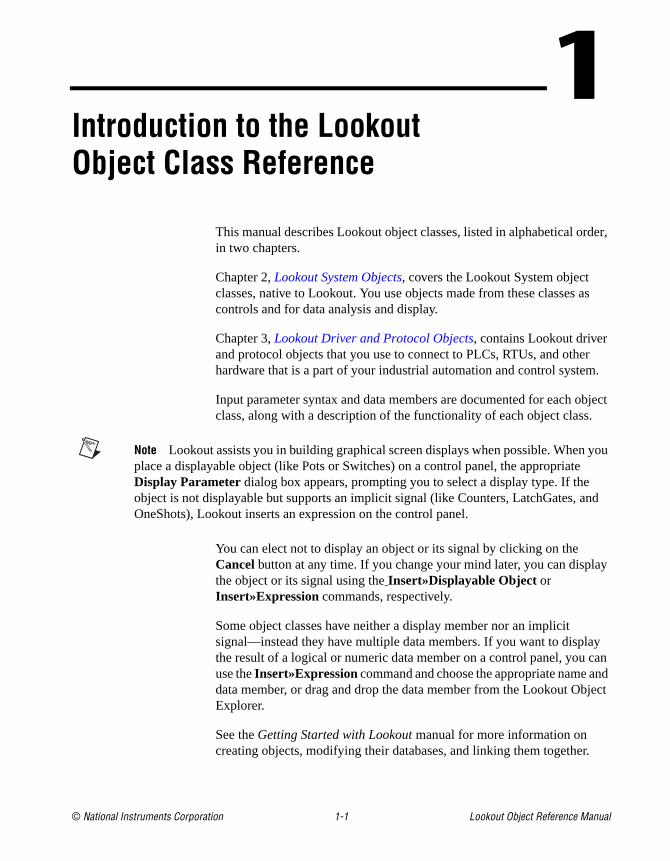
This manual describes Lookout object classes, listed in alphabetical order, in two chapters.
Chapter 2, Lookout System Objects, covers the Lookout System object classes, native to Lookout. You use objects made from these classes as controls and for data analysis and display.
Chapter 3, Lookout Driver and Protocol Objects, contains Lookout driver and protocol objects that you use to connect to PLCs, RTUs, and other hardware that is a part of your industrial automation and control system.
Input parameter syntax and data members are documented for each object class, along with a description of the functionality of each object class.
Note Lookout assists you in building graphical screen displays when possible. When you place a displayable object (like Pots or Switches) on a control panel, the appropriate Display Parameter dialog box appears, prompting you to select a display type. If the object is not displayable but supports an implicit signal (like Counters, LatchGates, and OneShots), Lookout inserts an expression on the control panel.
You can elect not to display an object or its signal by clicking on the Cancelbutton at any time. If you change your mind later, you can display the object or its signal using the Insert»Displayable Object or Insert»Expression commands, respectively.
Some object classes have neither a display member nor an implicit signal—instead they have multiple data members. If you want to display the result of a logical or numeric data member on a control panel, you can use the Insert»Expression command and choose the appropriate name and data member, or drag and drop the data member from the Lookout Object Explorer.
See the Getting Started with Lookout manual for more information on creating objects, modifying their databases, and linking them together.

© National Instruments Corporation 2-1 Lookout Object Reference Manual
2Lookout System Objects
This chapter describes Lookout System object classes, listed in alphabetical order. Input parameter syntax and data members are documented for each object class, along with a description of the functionality of each object class.

Chapter 2 Lookout System Objects
Lookout Object Reference Manual 2-2 www.natinst.com
AccumulatorAccumulator is a numeric totalizer. It samples the numeric Input any time the Sample value transitions from off to on, adding each new sample to the previous running total. It resets the totalized value to zero when Reset transitions from off to on.
Figure 2-1. Accumulator Definition Parameters Dialog Box
Input is a numeric expression while Sample and Reset are logical expressions.
The following HyperTrend demonstrates the relationship between Input , Sample, and Reset.
Reset
Input
Output
Sample
Chapter 2 Lookout System Objects
© National Instruments Corporation 2-3 Lookout Object Reference Manual
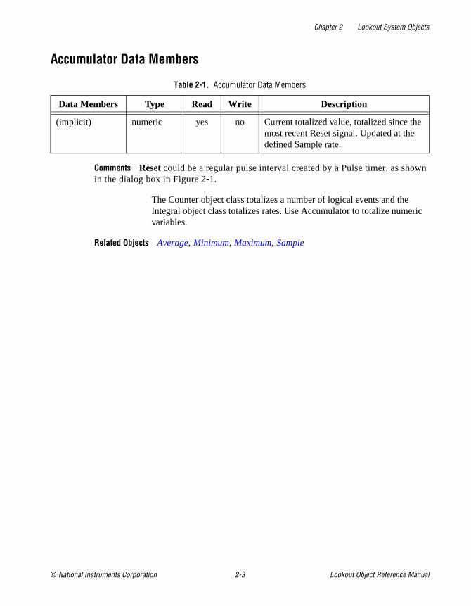
Accumulator Data Members
Comments Reset could be a regular pulse interval created by a Pulse timer, as shown in the dialog box in Figure 2-1.
The Counter object class totalizes a number of logical events and the Integral object class totalizes rates. Use Accumulator to totalize numeric variables.
Related Objects Average, Minimum, Maximum, Sample
Table 2-1. Accumulator Data Members
Data Members Type Read Write Description
(implicit) numeric yes no Current totalized value, totalized since the most recent Reset signal. Updated at the defined Sample rate.

Chapter 2 Lookout System Objects
Lookout Object Reference Manual 2-4 www.natinst.com
AlarmAlarm is a flexible and powerful object class you use to create various logical- and numeric-triggered alarms that are displayed in the alarm window.
Note You should first read about the Lookout alarm system in Chapter 9, Alarms, in the Lookout Developer’s Manual to aid you in designing the most efficient alarming scheme for your application.
Figure 2-2. Typical Settings for a Logical Style Alarm
There are two basic alarm types: Logical and Numeric. When Logical alarm is selected, Lookout prompts you to enter a logical expression in theCondition field. It then uses the logical Condition to trigger and reset the alarm. If the alarm Condition is true, the alarm is active, and if the condition is false, the alarm goes inactive. You can also connect an audio Wave file to individual logical alarms. See Playwave for additional information.
Lookout queues alarm .wav files, with up to 100 files in the queue. Each alarm .wav file plays completely before the next file plays. If more than 100 alarms fill the queue, new alarms cancel the currently playing files and begin playing instead.
Chapter 2 Lookout System Objects
© National Instruments Corporation 2-5 Lookout Object Reference Manual
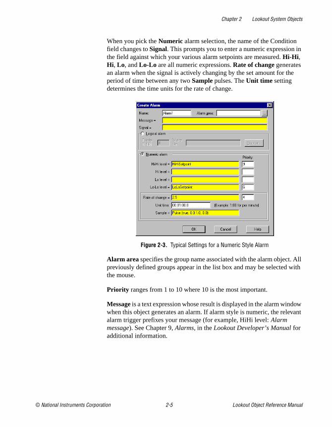
When you pick the Numeric alarm selection, the name of the Condition field changes to Signal. This prompts you to enter a numeric expression in the field against which your various alarm setpoints are measured. Hi-Hi , Hi , Lo, and Lo-Lo are all numeric expressions. Rate of change generates an alarm when the signal is actively changing by the set amount for the period of time between any two Sample pulses. The Unit time setting determines the time units for the rate of change.
Figure 2-3. Typical Settings for a Numeric Style Alarm
Alarm area specifies the group name associated with the alarm object. All previously defined groups appear in the list box and may be selected with the mouse.
Priority ranges from 1 to 10 where 10 is the most important.
Message is a text expression whose result is displayed in the alarm window when this object generates an alarm. If alarm style is numeric, the relevant alarm trigger prefixes your message (for example, HiHi level: Alarm message). See Chapter 9, Alarms, in the Lookout Developer’s Manual for additional information.

Chapter 2 Lookout System Objects
Lookout Object Reference Manual 2-6 www.natinst.com
Alarm Data Members.
Comments A common alarm condition is caused by a measured value going out of an acceptable range. For example, a storage tank whose level is too low or too high can generate several alarms: Hihi: Tank level is out of range , or Lo: Tank level
is out of range . If you use a numeric style alarm to trigger the alarm and if the tank level fluctuates or “jitters” around the alarm level settings, a new alarm record is generated in the alarm window each time the tank level fluctuates above or below the level settings. To alleviate this condition, you could use the Neutralzone object to filter out minor tank fluctuations.
Note Alarms can also be defined through parameter settings on object data members. Many times, this is the most efficient method of defining and creating alarm conditions. See Database-Generated Alarms in Chapter 9, Alarms, in the Lookout Developer’s Manual, and Editing Object Databases in Chapter 4, Using Lookout, in the Getting Started with Lookout manual.
Table 2-2. Alarm Data Members
Data Members Type Read Write Description
active logical yes no Result of logical alarm status. True if alarm is active and false if alarm is inactive.
hi logical yes no Result of numeric alarm hi data member status.
hihi logical yes no Result of numeric alarm hihi data member status.
lo logical yes no Result of numeric alarm lo data member status.
lolo logical yes no Result of numeric alarm lolo data member status.
rate logical yes no Result of numeric alarm rate data member status.

Chapter 2 Lookout System Objects
© National Instruments Corporation 2-7 Lookout Object Reference Manual
$Alarm$Alarm is a global object. It makes available global alarm data such as the number of currently active alarms.
You can use $Alarm data members just like other data members. By inserting an expression you can display the number of active alarms in any particular group. Or, by connecting a pushbutton to an acknowledge data member, operators can acknowledge alarms through pushbutton selection.
Assume, for example, that you want to create a pushbutton that acknowledges all alarms. First create a pushbutton object. Next, use the Object»Edit Connections… command to connect the pushbutton (Pb1) to the .ack data member of $Alarm. Such a connection is shown in the following illustration.
Figure 2-4. Edit Connections Dialog Box for using $Alarm
The expression(Pb1) acknowledges all active alarms any time the pushbutton is depressed. You could make similar connections to acknowledge individual alarm areas.

Chapter 2 Lookout System Objects
Lookout Object Reference Manual 2-8 www.natinst.com
You can define new alarm areas through Alarm objects and by modifying object database parameters. As you create each new alarm area, Lookout adds new readable and writable data members to the $Alarm object. $Alarm data members are described in the following table.
$Alarm Data Members
Table 2-3. $Alarm Data Members
Data Member Type Read Write Description
ack logical no yes Upon transition from FALSE to TRUE, acknowledges all alarms.
Ackselected logical no yes Upon transition from FALSE to TRUE, acknowledges all selected alarms.
ActivatePanel logical no yes Calls Alarm Window upon transition from FALSE to TRUE, making it visible on the screen.
Active numeric yes no Total number of currently active alarms (that is, alarm conditions that still exist).
Groupname text yes no Alarm area name associated with the most recent alarm.
Groupname.ack logical no yes Upon transition from FALSE to TRUE, acknowledges all alarms within the specified group.
Groupname.active numeric yes no Number of currently active alarms within the specified group.
Groupname.unacked numeric yes no Number of unacknowledged alarms within the specified group.
Message text yes no Text of the message of the most recent alarm
MinimizePanel logical no yes Closes Alarm Window upon transition from FALSE to TRUE, changing it to an icon.
Priority numeric yes no Alarm priority associated with the most recent alarm.

Chapter 2 Lookout System Objects
© National Instruments Corporation 2-9 Lookout Object Reference Manual
Comments Groupname in the preceding table represents the name of any specified alarm area. The $Alarm object contains an .active , .unacked , and .ack data member for every alarm area.
Using $Alarm with Other ObjectsEvery time a new alarm appears in Lookout, $Alarm.Message , $Alarm.Name , $Alarm.Groupname , and $Alarm.Priority are updated with the appropriate information for the new alarm. Then $Alarm.Update pulses high to alert you that those four data members contain fresh values.
These data members can serve many purposes, but they are specifically designed to work with the Pager object class. In a typical application, you could use $Alarm.Update to initiate a page, possibly including the other four data members in the text of the page. With this system you can also filter which alarms you want to page, and which alarms the pager ignores.
Priority01.active – Priority10.active
numeric yes no Number of currently active alarms of the specified priority.
Priority01.unacked – Priority10.unacked
numeric yes no Number of unacknowledged alarms of the specified priority.
Silence logical no yes Turns off alarm sounds when set to TRUE.
Name text yes no Object name associated with the most recent alarm.
Unacked numeric yes no Total number of unacknowledged alarms (that is, alarm conditions that have not yet been acknowledged).
Update logical yes no Pulses high every time there is a new alarm.
Table 2-3. $Alarm Data Members (Continued)
Data Member Type Read Write Description

Chapter 2 Lookout System Objects
Lookout Object Reference Manual 2-10 www.natinst.com
AlternatorAlternator is an object class Lookout uses to control a series of devices with various commands. Typically this means rotating the usage of the devices at specified times.
Figure 2-5. Alternator Definition Parameters Dialog Box
Devices determines the maximum number of devices that can be controlled by the alternator.
Maximum run time is the maximum amount of time that any one device is allowed to run continuously. This function can be disabled by entering 0.
Delay between device starts is the minimum amount of time between device starts that are initiated by the alternator object. This function can be disabled by entering 0.
Device failure alarm priority determines the priority level of alarms generated by the alternator. This defaults to 5.
Device response time is the amount of time the alternator waits for a response from a device before activating an alarm. This function can be disabled for individual devices by not connecting anything to the Response data member.
Device name is a string describing the type of device that is being controlled by the alternator. This is used to create the alarm messages and is also the name of the group to which the alarms belong.

Chapter 2 Lookout System Objects
© National Instruments Corporation 2-11 Lookout Object Reference Manual
Timer update specifies the resolution of the timers used by the alternator to decide which devices to turn on and off. This also specifies how often the alternator updates the ElapsedTime and RunTime data members.
Alternator Data Members
Table 2-4. Alternator Data Members
Data Member Type Read Write Description
Advance logical no yes Turns on the next device in the sequence and turns off the last device in the sequence
Command numeric no yes How many devices the alternator is to have running
DeviceConnect1 - DeviceConnect100
logical yes no States whether device is in the active sequence considered by the alternator
DeviceOn1 - DeviceOn100
logical yes no Confirmation of the actual device state
DeviceRequest1 - DeviceRequest100
logical yes no Output to whatever drives the device
ElapsedTime1 - ElapsedTime100
numeric yes no Elapsed time device has been on since last reset
HOAmode1 - HOAmode100
numeric no yes States whether device is in Hand, Off, or Auto mode
Reset1 - Reset100 logical no yes Used to reset the ElapsedTime data member
Response1 - Response100
logical no yes Response bit from device
RunTime1 - RunTime100
numeric yes no Elapsed time device has been on continuously
Chapter 2 Lookout System Objects
Lookout Object Reference Manual 2-12 www.natinst.com
Connecting the AlternatorThe DeviceRequest data members should be connected to whatever drivers are controlling your devices. Notice that when you connect the DeviceRequest data member to anything, the DeviceConnect data member goes high. This connection is the only one required for the alternator to consider your device connected. The RunTime, ElapsedTime, DeviceConnect, and DeviceOn data members can be connected to or not depending on whether you want that information.
The Command data member is the essential writable data member to connect to. The connection to Command can be any numeric expression, but a pot is probably most convenient, especially for testing and demonstration purposes. It only accepts values in the integer range from zero to the number of Device connections specified as a parameter. To theResponse data members should be connected a response bit from each device. If no connection is made to Response the alternator does not require any response from the device. The Advance, Reset, and HOAmode data members are not essential either; You need only make connections to them if you want their functionality. Advance and Reset typically are connected to pushbuttons, and HOAmode typically connects to a pot. The HOAmode data member only accepts values in the integer range from one to three.
Command and AdvanceThe Command data member is the number of devices that the alternator is to have running at one time. When you send the alternator its first command, it requests a corresponding number of devices to turn on. TheDeviceRequest data member for each of these devices goes high to signify this. When the devices respond that they are in fact on via the Response data member, (if it is connected) the alternator recognizes that the device is on and the DeviceOn data member goes high. Conversely, if the Command data member specifies that devices are to be turned off, the DeviceRequest data members for the corresponding number of devices goes low. The devices should then respond accordingly via the Response data member.
When you give the alternator a numeric command, it takes into account the number of devices currently running, and makes its requests accordingly. Because of this, it is important to know how the alternator counts the number of devices running. Devices running as a result of a Hand command from the HOAMode data member are NOT counted. All other running devices (including those with active alarms) are.

Chapter 2 Lookout System Objects
© National Instruments Corporation 2-13 Lookout Object Reference Manual
When the alternator is asked to turn on a new device it chooses the device that has been off the longest. When asked to turn off a device it chooses the device that has been on the longest.
The Advance command turns on one device and turns off another device.
Maximum Run Time and Delay OperationThe Maximum run time parameter specifies how long any one device can be running. Each device has its own timer to ensure that this is enforced. When one of these timers informs the alternator that its device has been on for the maximum allowed time, the alternator executes a command identical to the Advance command. Notice that there are two cases where the maximum time limit is not enforced strictly. One of them is when you have turned on a device via the HOAmode data member. (Its operation is discussed in the next section.) The other is when it conflicts with the operation of the Delay between device starts feature.
Delay between device starts is specified as a parameter, and limits how often the alternator can turn on devices. An example of the operation of the Delay between device starts would be beginning with a new alternator that has none of the devices on. You issue a command using the Command data member of 3. If the delay feature is in use, the alternator sends three ON requests separated by the amount of time specified by Delay between device starts.
Hand-Off-Auto ModesThe HOAmode data member gives the user direct control over each device. The integer value of this numeric data member corresponds to an operating mode. (See Table 2-5.) When the HOAmode data member is in Auto mode (as it is by default if you never connect anything to this data member) it is subject to the commands of the alternator. Its DeviceConnect data member will be high to signify that the alternator recognizes it. When you select Hand mode, two things happen: The device is disconnected and is sent an on request. Similarly in Off mode the device is disconnected and requested off. In these two modes, the alternator does not recognize or request anything of these devices. If you select Auto mode again, the device is reconnected.
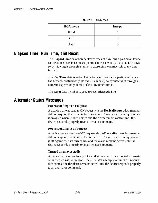
Chapter 2 Lookout System Objects
Lookout Object Reference Manual 2-14 www.natinst.com
Elapsed Time, Run Time, and ResetThe ElapsedTime data member keeps track of how long a particular device has been on since its last reset (or since it was created). Its value is in days, so by viewing it through a numeric expression you may select any time format.
The RunTime data member keeps track of how long a particular device has been on continuously. Its value is in days, so by viewing it through a numeric expression you may select any time format.
The Reset data member is used to reset ElapsedTime.
Alternator Status MessagesNot responding to on request
A device that was sent an ON request via the DeviceRequest data member did not respond that it had in fact turned on. The alternator attempts to turn it on again when its turn comes and the alarm remains active until the device responds properly to an alternator command.
Not responding to off request
A device that was sent an OFF request via the DeviceRequest data member did not respond that it had in fact turned off. The alternator attempts to turn it off again when its turn comes and the alarm remains active until the device responds properly to an alternator command.
Turned on unexpectedly
A device that was previously off and that the alternator expected to remain off turned on without reason. The alternator attempts to turn it off when its turn comes, and the alarm remains active until the device responds properly to an alternator command.
Table 2-5. HOA Modes
HOA mode Integer
Hand 1
Off 2
Auto 3

Chapter 2 Lookout System Objects
© National Instruments Corporation 2-15 Lookout Object Reference Manual
Turned off unexpectedly
A device that was previously on and that the alternator expected to remain on turned off without reason. The alternator attempts to turn it on when its turn comes, and the alarm remains active until the device responds properly to an alternator command.
Not responding to HOA command
A device did not respond properly to a command from the HOAmode data member. The alternator attempts to request it when its turn comes, and the alarm remains active until the device responds properly to an alternator command.

Chapter 2 Lookout System Objects
Lookout Object Reference Manual 2-16 www.natinst.com
AnimatorThe Animator object class provides full graphical animation including horizontal and vertical motion, dynamic resizing and visibility, dynamic symbol sequencing and programmable color changes.
When you first create an animator object, the Select graphic dialog box appears.
Figure 2-6. Select Graphic Dialog Box
Select the graphic you want to animate. To animate colors, you must select a Windows Metafile (.wmf ). A moving animation must have the series of images you want to animate arranged in a single bitmap so that each cell of the animation can be defined by a grid of rows and columns.
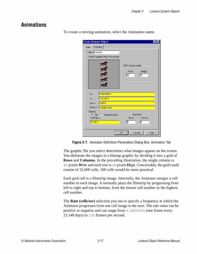
Chapter 2 Lookout System Objects
© National Instruments Corporation 2-17 Lookout Object Reference Manual
AnimationsTo create a moving animation, select the Animation name.
Figure 2-7. Animator Definition Parameters Dialog Box, Animation Tab
The graphic file you select determines what images appear on the screen. You delineate the images in a bitmap graphic by dividing it into a grid of Rows and Columns. In the preceding illustration, the single column is 48 pixels Wide and each row is 28 pixels High. Conceivably, the grid could consist of 32,000 cells. 100 cells would be more practical.
Each grid cell is a filmstrip image. Internally, the Animator assigns a cell number to each image. It normally plays the filmstrip by progressing from left to right and top to bottom, from the lowest cell number to the highest cell number.
The Rate (cells/sec) selection you use to specify a frequency at which the Animator progresses from one cell image to the next. The rate value can be positive or negative and can range from 0.0000005 (one frame every 23.148 days) to 100 frames per second.

Chapter 2 Lookout System Objects
Lookout Object Reference Manual 2-18 www.natinst.com
If the rate value is negative, the Animator plays the filmstrip backwards, starting at the last cell.
You can use the Cell selection in the definition dialog box to identify a particular cell number to display. For example, you might use this selection to display a specific image when a PLC register is equal to a particular value. This is similar to the multistate object, but can provide many more states, depending on the number of cells in the bitmap.
The X and Y parameters specify the horizontal and vertical position of the image, respectively. These numeric parameters range from 0 to 100 , and together provide the X-Y position of the image as a percent of the Animator dimension on a control panel.
Size is a numeric parameter that ranges from 0 to 100 percent, where 100 percent is the full size of a single cell as specified by W and H.
Visible is a logical parameter that causes to the image to appear when it goes true and disappear when it goes false.
Color AnimationTo create color changes programmatically, select the Color tab.
With this option, you can set the color map on a .wmf graphic using a series of five logical conditions and a default state. If no condition is true, the default state (or color map) is imposed.
You can choose a custom color map by clicking on the color sample associated with each logical condition. You can then select any color from the palette available on your computer.

Chapter 2 Lookout System Objects
© National Instruments Corporation 2-19 Lookout Object Reference Manual
Select the Show Original Colors box if you want the original color map of the .wmf file to be imposed for that condition.
Figure 2-8. Animator Definition Parameters Dialog Box, Color Tab
Gray Proximity determines the color saturation point at which the selected color replaces an original color. When this parameter is set to 0, most colors change. When this parameter is set to 100 , most colors will not change. You can test the effects of this setting by putting your cursor over the color button and observing the change in the graphic displayed in the dialog box window.
Notice that the if and else if statements are evaluated in sequence. If several conditional expressions are true at once, Multistate displays the graphic associated with the first true expression.
For instance, if your If parameters use less-than comparisons, such as PumpSpeed<50, the following Else if parameter must have a larger comparison value, such as PumpSpeed<75. If you use a smaller comparison value, such as PumpSpeed<25, the color change will not take place. In other words, the comparison values must be used from smallest to largest.

Chapter 2 Lookout System Objects
Lookout Object Reference Manual 2-20 www.natinst.com
In the same way, if you are using greater-than comparisons, such as PumpSpeed>50, you must list your comparison values from largest to smallest, so that the next Else If parameter would have to be something like PumpSpeed>25.
Put If parameters using equality, such as PumpSpeed=50, before parameters using inequalities.
A few minutes experimentation should help you understand the interactions of the color choice conditions.
Animator Data Members
Comments Consider using an Integral object instead of a Counter/Pulse combination when trying to achieve smooth animation.
Related Objects DialGauge, Gauge, Multistate, Pipe, Spinner
Table 2-6. Animator Data Members
Data Member Type Read Write Description
none — — — Animator objects do not have data members

Chapter 2 Lookout System Objects
© National Instruments Corporation 2-21 Lookout Object Reference Manual
AverageAverage actively calculates the average value of Data over time. Average is only active when the Enable expression is true and resets to zero when the Reset expression transitions from off to on. Average also maintains an array of up to 35 previous averaged values. If Enable is left blank, the object always actively calculates the average.
Figure 2-9. Average Definition Parameters Dialog Box
Data is a numeric expression while Reset and Enable are logical expressions.
Average Data Members
Table 2-7. Average Data Members
Data Members Type Read Write Description
(implicit) numeric yes no Current average calculated since the most recent Reset signal. Updated approximately once per second.
1 – 35 numeric yes no Previous average values. Signal 1 is the most recent prior average since the Reset signal went high.
DataReset logical no yes Upon transition from FALSE to TRUE, resets to zero all data members—including the current average and all previous averages.

Chapter 2 Lookout System Objects
Lookout Object Reference Manual 2-22 www.natinst.com
Comments The Reset expression could be a regular pulse interval created by a TimeOfxxxx timer, so that the pulse is synchronized to the top of the hour or day. For example, if you want to calculate the daily average flow rate, use the output signal from a TimeOfDay timer or a daily Spreadsheet object to reset the average calculation at the beginning of each day. If you want to calculate the average flow rate only when a pump is running, use the input signal from the pump motor relay in the Enable parameter.
Related Objects Minimum, Maximum, Sample

Chapter 2 Lookout System Objects
© National Instruments Corporation 2-23 Lookout Object Reference Manual
CounterCounter counts the number of times that the Count expression transitions from off to on. The digital display shows the number of pulses counted so far, and is updated approximately once per second—however, it can receive and count multiple pulses within a given second. The counter can count to just under 4,503,600,000,000,000 or 142,710 years worth of pulses at one pulse per second. When the Reset expression transitions from off to on, the counter resets to zero.
Figure 2-10. Counter Definition Parameters Dialog Box
Both Count and Reset are logical expressions.
Counter Data Members
Comments You should not use Counters to count external pulse signals that cycle more often than about once per second. For higher counting speeds, use the accumulator capabilities built into your PLC.
Related Objects Accumulator, Integral
Table 2-8. Counter Data Members
Data Member Type Read Write Description
(implicit) numeric yes no numeric total of pulse count

Chapter 2 Lookout System Objects
Lookout Object Reference Manual 2-24 www.natinst.com
DataTableDataTables are used in the following applications:
• Multiplexing various data sources into a single display template.
• Importing or exporting large quantities of data to other applications using DDE. (Unlike the DdeTable, the DataTable provides bidirectional DDE communications. See DdeTable.)
• Networking multiple Lookout nodes (see Chapter 5, Networking, in the Lookout Developer’s Manual).
A DataTable contains a matrix of rows and columns, much like a spreadsheet. Each column is represented by a letter (A – IV). Each row is represented by a number (1 – 1,000). Letter-number combinations represent intersections of rows and columns. Such intersections are called cells. Any given cell contains a value. A cell value can be numeric, logical, or textual.
Note DataTables are advanced tools that require a mastery of Lookout object databases. Make sure you understand editing, connecting to, and using object databases and aliases before creating a DataTable object. See Chapter 4, Using Lookout, and Chapter 5, Developer Tour, in the Getting Started with Lookout manual for more information on object databases.
The following dialog box appears when you create a DataTable:
Figure 2-11. DataTable Definition Parameters Dialog Box

Chapter 2 Lookout System Objects
© National Instruments Corporation 2-25 Lookout Object Reference Manual
Specify DDE parameters if you want to use the DataTable to exchange large quantities of data from an external source (such as Excel) continuously, with both Lookout and the other program running. See Chapter 6, Dynamic Data Exchange, of the Lookout Developer’s Manual for more information on DDE connections to other programs.
Specify Local if you are using the DataTable to import or export data from Lookout into or out of a static file. Also specify Local if you are using the DataTable to multiplex various signals into a single display or graphic template.
To exchange data with another DataTable running in another Lookout process, you can use ordinary Lookout connections.
The export and import data members control the transfer of data between Lookout and a Microsoft Excel spreadsheet. The spreadsheet filename must be entered in the Import/Export section of the Create table dialog box.
Note The data table import and export data members only work with Microsoft Excel Version 4 at this time. This feature does not work with Excel Version 5 or greater.
Instead of entering a file name in the Import/Export dialog box, you can enter a Lookout expression in the Filename field. You can then import and export different files using a switch setting, a text entry box, or some other expression input. If something goes wrong with the transfer of data, including data corruption, Lookout reports an alarm.
Click on the Clear table if import error checkbox to clear the DataTable before importing either from a spreadsheet or an ODBC database. This only affects what happens if there is an error during the import. If there are no errors during the import, the imported data always replaces the old data in the table. However, if the checkbox is selected, the DataTable is always cleared before starting an import, so that, if an error occurs, the DataTable is left empty. If the checkbox is not checked and an error occurs, the old data is left in the table.

Chapter 2 Lookout System Objects
Lookout Object Reference Manual 2-26 www.natinst.com
Figure 2-12. DataTable Definition Parameters Dialog Box; Import from ODBC Database
The Connect String= field specifies the DataSource Name (DSN) as well as any other parameters needed by the ODBC driver to make the connection to your chosen data source.
The SQL command= field is where you enter the SQL string you want to pass to the ODBC driver. See the SqlExec object for more information about using SQL queries in Lookout.
Use the Clear table if import error checkbox to clear the DataTable before importing either from an ODBC database or a spreadsheet. This only affects what happens if there is an error during the import. If there are no errors during the import, the imported data always replaces the old data in the table. However, if the checkbox is selected, the DataTable is always cleared before starting an import, so that, if an error occurs, the DataTables left empty. If the checkbox is not checked and an error occurs, the old data is left in the table.
Multiplexing Displays and Graphics You can use DataTables to multiplex signals into a single control panel, used as a template. For instance, assume you have nine identical pump stations. At each site you have a single PLC monitoring the pressure, flow rate, and status of two pumps. You are also controlling an analog output with an operator setpoint from Lookout. Instead of developing nine identical control panels in Lookout, you can build just one panel and multiplex the signals from the nine sites into a single set of graphics.

Chapter 2 Lookout System Objects
© National Instruments Corporation 2-27 Lookout Object Reference Manual
The following figure is a graphical representation of the connections for a possible DataTable.
Figure 2-13. Graphical Representation of a DataTable Showing Connections
Note At this time there is no actual view in Lookout for you to see this table. It is a representation, not a screen capture of a Lookout dialog box or display element.
Each row of the table is connected to the site name, the data you want to keep track of from the PLC at that site, and a place for the operator setpoint data for that site.
Notice the names of the nine PLCs (PLC1, PLC2…). Each value has an alias (press , flow , pmp1, pmp2). Each cell represents a connection made from that PLC output to the that cell of the DataTable.
The open column D represents the connection of a single Pot object called Setpoint to the column—not to individual cells. This way Lookout only changes the value of a cell in column D when that particular row has been made active. You connect the individual cells in column D (D1 through D9) to the correct holding registers (outputs) on the respective PLCs. For example, Table1.D1 would be connected to the appropriate data member of PLC1 — Table1.D2 to the appropriate data member of PLC2, and so on. In other words, when you intend to multiplex signals to a panel through a data table connect inputs from a PLC or RTU to individual cells. Connect operator setpoints (outputs) to columns.
Setpoint Value
Colum
n

Chapter 2 Lookout System Objects
Lookout Object Reference Manual 2-28 www.natinst.com
DataTable ExampleTo practice using a DataTable, you can create a PLC simulator as shown in the following illustration. You can use a separate control panel for each PLC output simulator, or place all the objects you make on one panel.
Use two slider pots as your pressure and flow outputs, and two switches as the on/off indicators for pumps one and two. You can use the dial gauge at the bottom to check the operator input, Setpoint . Instead of connecting the cells of your data table to PLC outputs, you connect directly to the Lookout objects, named after the outputs for clarity.
You should create at least three sets of PLC input/output simulators. The following example refers to the 9 PLCs mentioned in the Multiplexing Displays and Graphics section, but you can explore using a data table using 2 or 3 simulators.
Connect specific DataTable cells from the D column to the Setpoint indicator for each PLC simulator.
Site1Pressure
Site1Flow
pump1_1 (simulates PLC1.pmp1)
pump1_2 (simulates PLC1.pmp2)
Setpoint indicator(operator input)
(simulates PLC1.flow)
(simulates PLC1.press)
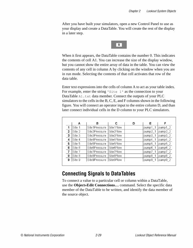
Chapter 2 Lookout System Objects
© National Instruments Corporation 2-29 Lookout Object Reference Manual
After you have built your simulators, open a new Control Panel to use as your display and create a DataTable. You will create the rest of the display in a later step.
When it first appears, the DataTable contains the number 0. This indicates the contents of cell A1. You can increase the size of the display window, but you cannot show the entire array of data in the table. You can view the contents of any cell in column A by clicking on the window when you are in run mode. Selecting the contents of that cell activates that row of the data table.
Enter text expressions into the cells of column A to act as your table index. For example, enter the string "Site 1" as the connection to your DataTable A1.txt data member. Connect the outputs of your PLC simulators to the cells in the B, C, E, and F columns shown in the following figure. You will connect an operator input to the entire column D, and than later connect individual cells in the D column to your PLC simulators.
Connecting Signals to DataTablesTo connect a value to a particular cell or column within a DataTable, use the Object»Edit Connections… command. Select the specific data member of the DataTable to be written, and identify the data member of the source object.

Chapter 2 Lookout System Objects
Lookout Object Reference Manual 2-30 www.natinst.com
Connecting to CellsThe value from Site1Pressure is numeric. To write the value of Site1Pressure into cell B1, connect the simulated output to B1—not B1.logical or B1.txt . The Edit connection dialog box is shown in the following illustration.
Figure 2-14. Edit Connections Dialog Box
After you establish a connection to a cell, the value within the cell changes any time the expression changes. Any time the value of Site1Pressure changes, the value within cell B1 changes.

Chapter 2 Lookout System Objects
© National Instruments Corporation 2-31 Lookout Object Reference Manual
Connecting to ColumnsTo connect the value of the Setpoint potentiometer to column D, selectD—not D.logical or D.txt —as shown in the following illustration. As with the previous value, you use D because you are using a numerical value. There is no number following the D because you are connecting to a column, not a cell.
Figure 2-15. Edit Connections Dialog Box
Once a connection to a column is established, the value within the cell at the currently selected row changes when the expression changes. So, if you activate row 4 and change the value of Setpoint changes, the value within cell D4 changes. No other cells are affected until you move the cursor to activate another row and the operator adjusts the pot.

Chapter 2 Lookout System Objects
Lookout Object Reference Manual 2-32 www.natinst.com
Reading a Cell Value Back to a Lookout ObjectWhen you connect the display panel potentiometer called Setpoint to Table1.D , you should configure your pot with the appropriate Remote parameter to ensure that it automatically adjusts to track the value in any cell (within the specified column) when the cursor moves to a new row.

Chapter 2 Lookout System Objects
© National Instruments Corporation 2-33 Lookout Object Reference Manual
The Display PanelNow that your DataTable (called Table1 ) is complete, you can return to your display panel (where you placed the DataTable object initially) and begin to build a single control panel that allows you to multiplex the data from your PLCs. A sample panel is shown in the following illustration.
Instead of using expressions that reference the actual values from your driver objects to display values, use the column names from Table1 . For instance, the bar graph and numeric readout for Pressure both represent the expression Table1.B . The actual value for Table1.B depends on the what row is currently active in the DataTable. In the illustration row 1 is active, so all the expressions return the value in their respective columns at row 4. The callouts in the picture indicate how the control panel was developed. All are Lookout expressions except the Pot and the DataTable, which are displayable objects.
Table1.B
Table1.B
Table1.C
Table1 display
Table1.E.logical
Table1.F.logical
(no connection necessary)
Potentiometer connected to Table1.D(Column D)

Chapter 2 Lookout System Objects
Lookout Object Reference Manual 2-34 www.natinst.com
Operating Your Multiplexed PanelThe plate in bottom right corner of the control panel is the DataTable object (Table1 ). To view a different site with the control panel (that is, to activate a different row, thereby selecting a different PLC), click on Table1 and the following dialog box should appear.
By selecting a site, you connect your control panel to the PLC at that site. This is referred to as moving the cursor to that row.
DataTable CursorsThe cursor is a DataTable pointer that you can move from row to row to activate the values in the cells of that row. There are several methods for controlling the location of the cursor:
• Connect a numeric expression to the cursor data member. A typical example would be to connect a potentiometer (minimum = 1, maximum = the number of rows in table, resolution = 1) to the cursor.
• Connect logical expressions to appropriate row numbers. A typical example would be to create a pushbutton for every row and then connect them to their respective row numbers.
This list box gets the rownames from Column Ain the Data Table
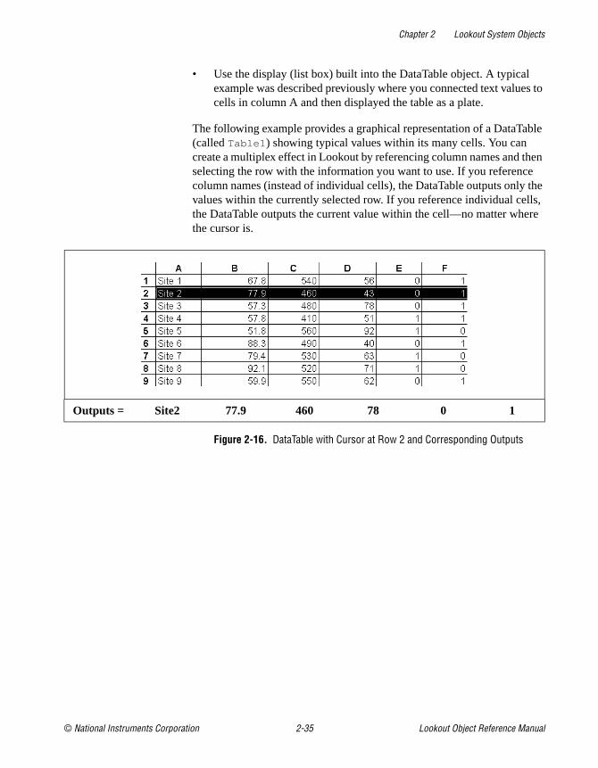
Chapter 2 Lookout System Objects
© National Instruments Corporation 2-35 Lookout Object Reference Manual
• Use the display (list box) built into the DataTable object. A typical example was described previously where you connected text values to cells in column A and then displayed the table as a plate.
The following example provides a graphical representation of a DataTable (called Table1 ) showing typical values within its many cells. You can create a multiplex effect in Lookout by referencing column names and then selecting the row with the information you want to use. If you reference column names (instead of individual cells), the DataTable outputs only the values within the currently selected row. If you reference individual cells, the DataTable outputs the current value within the cell—no matter where the cursor is.
Figure 2-16. DataTable with Cursor at Row 2 and Corresponding Outputs
Outputs = Site2 77.9 460 78 0 1
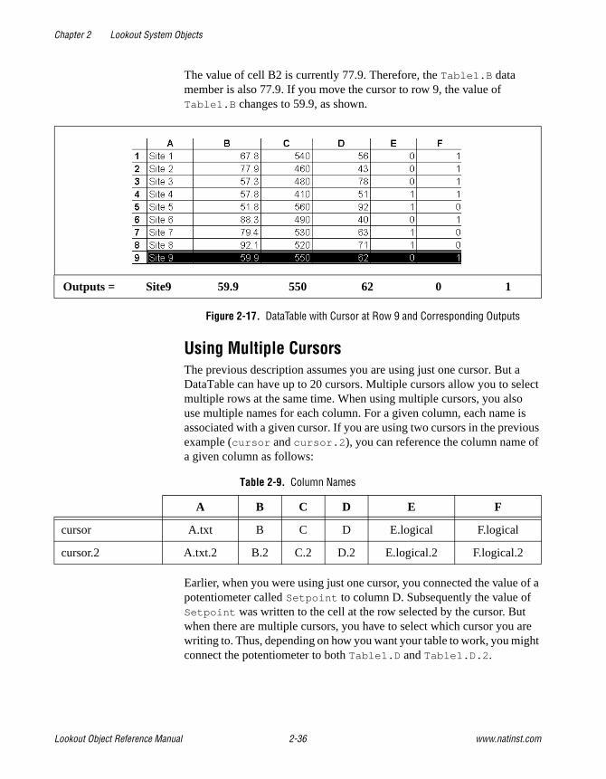
Chapter 2 Lookout System Objects
Lookout Object Reference Manual 2-36 www.natinst.com
The value of cell B2 is currently 77.9. Therefore, the Table1.B data member is also 77.9. If you move the cursor to row 9, the value of Table1.B changes to 59.9, as shown.
Figure 2-17. DataTable with Cursor at Row 9 and Corresponding Outputs
Using Multiple CursorsThe previous description assumes you are using just one cursor. But a DataTable can have up to 20 cursors. Multiple cursors allow you to select multiple rows at the same time. When using multiple cursors, you also use multiple names for each column. For a given column, each name is associated with a given cursor. If you are using two cursors in the previous example (cursor and cursor.2 ), you can reference the column name of a given column as follows:
Earlier, when you were using just one cursor, you connected the value of a potentiometer called Setpoint to column D. Subsequently the value of Setpoint was written to the cell at the row selected by the cursor. But when there are multiple cursors, you have to select which cursor you are writing to. Thus, depending on how you want your table to work, you might connect the potentiometer to both Table1.D and Table1.D.2 .
Outputs = Site9 59.9 550 62 0 1
Table 2-9. Column Names
A B C D E F
cursor A.txt B C D E.logical F.logical
cursor.2 A.txt.2 B.2 C.2 D.2 E.logical.2 F.logical.2
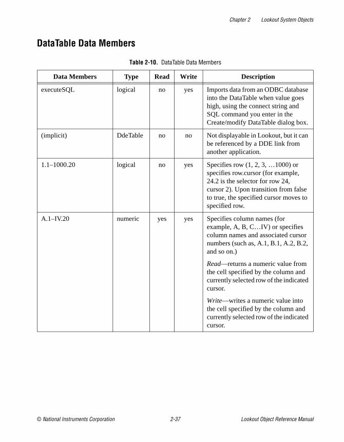
Chapter 2 Lookout System Objects
© National Instruments Corporation 2-37 Lookout Object Reference Manual
DataTable Data Members
Table 2-10. DataTable Data Members
Data Members Type Read Write Description
executeSQL logical no yes Imports data from an ODBC database into the DataTable when value goes high, using the connect string and SQL command you enter in the Create/modify DataTable dialog box.
(implicit) DdeTable no no Not displayable in Lookout, but it can be referenced by a DDE link from another application.
1.1–1000.20 logical no yes Specifies row (1, 2, 3, …1000) or specifies row.cursor (for example, 24.2 is the selector for row 24, cursor 2). Upon transition from false to true, the specified cursor moves to specified row.
A.1–IV.20 numeric yes yes Specifies column names (for example, A, B, C…IV) or specifies column names and associated cursor numbers (such as, A.1, B.1, A.2, B.2, and so on.)
Read—returns a numeric value from the cell specified by the column and currently selected row of the indicated cursor.
Write—writes a numeric value into the cell specified by the column and currently selected row of the indicated cursor.

Chapter 2 Lookout System Objects
Lookout Object Reference Manual 2-38 www.natinst.com
A.logical.1 – IV.logical.20
logical yes yes Specifies column names (for example, A.logical, B.logical, C.logical, …IV.logical) or specifies column names and associated cursor numbers (such as, A.logical.1, B.logical.1, A.logical.2, B.logical.2, and so on.)
Read—returns a logical value from the cell specified by the column and currently selected row of the indicated cursor.
Write—writes a logical value into the cell specified by the column and currently selected row of the indicated cursor.
A.txt.1 – IV.txt.20 text yes yes Specifies column names (for example, A.txt, B. txt, C. txt, …IV. txt) or specifies column names and associated cursor numbers (such as, A. txt.1, B. txt.1, A. txt.2, B. txt.2, and so on.)
Read—returns a text value from the cell specified by the column and currently selected row of the indicated cursor.
Write—writes a text value into the cell specified by the column and currently selected row of the indicated cursor.
A1 – IV16384 numeric yes yes Specified cell interpreted as numeric value
A1.logical –IV16384.logical
logical yes yes Specified cell interpreted as logical value
A1.txt –IV16384.txt text yes yes Specified cell interpreted as text value
Table 2-10. DataTable Data Members (Continued)
Data Members Type Read Write Description

Chapter 2 Lookout System Objects
© National Instruments Corporation 2-39 Lookout Object Reference Manual
Related Objects DdeTable, DdeLink
Cursor.1 – Cursor.20 numeric yes yes Specifies the currently selected row of the indicated cursor.
enable logical yes yes If TRUE (the default), enables DDE. If FALSE, disables DDE. The default value is on. The input is ignored for non-DDE TextEntry objects.
export logical no yes When this input transitions from false to true, the Lookout data table is exported to the designated spreadsheet file.
import logical no yes When this input transitions from false to true, the Lookout data table imports data from the designated spreadsheet.
Modified logical yes no Pulses TRUE when any cell value in the DataTable changes.
Update logical yes no Pulses each time the cursor changes rows. Often used to “call up” a control panel.
Table 2-10. DataTable Data Members (Continued)
Data Members Type Read Write Description

Chapter 2 Lookout System Objects
Lookout Object Reference Manual 2-40 www.natinst.com
DdeLinkDdeLink creates a unidirectional Dynamic Data Exchange (DDE) link to another application. The other application could be running on the same computer or on another computer over a network. DdeLink objects provide an easy way to import remote values into Lookout. See Chapter 5, Dynamic Data Exchange, in the Lookout Developer’s Manual for more information on DDE. For each DdeLink object you define, Lookout creates a separate link to the other application. If you need to import large quantities of data, you should use the DdeTable or DataTable object. See DdeTable and DataTable for more information.
DdeLinks on Same ComputerIf you are importing values from another application running on the same computer, your DDE parameters will look similar to the ones in the following illustration.
Figure 2-18. DdeLink Definition Parameters Dialog Box (Same Computer)
Service specifies the application name, Topic specifies the file, and Item points to the individual value (r1c1 refers to the cell at row1, column1. Unfortunately, Excel does not support the more convenient A1 cell references with DDE).
DdeLinks to Remote ComputerIf you are importing values from another application running on a remote computer, your DDE parameters will look similar to the ones in the following illustration.

Chapter 2 Lookout System Objects
© National Instruments Corporation 2-41 Lookout Object Reference Manual
Figure 2-19. DdeLink Definition Parameters Dialog Box (Remote Computer)
Notice the differences in the Service, Topic, and Item parameters. The backslashes (\\ ) and dollar signs ($) are standard requirements for making network connections in Microsoft Windows. ComputerName specifies the network name of the computer you are connecting to. If you are connecting to a value in another Lookout application, ProcessFile is the Lookout file name running on the remote computer, and Name refers to the name you are linking to.
DdeLink Data Members
Related Objects DdeTable, DataTable
Table 2-11. DdeLink Data Members
Data Members Type Read Write Description
(implicit) numeric yes no DDE link interpreted as numeric value.
enable logical yes yes If TRUE (the default), enables DDE. If FALSE, disables DDE. This input is ignored for non-DDE TextEntry objects.
hot logical yes no Status of DDE link.
logical logical yes no DDE link interpreted as logical value.
txt text yes no DDE link interpreted as text value.

Chapter 2 Lookout System Objects
Lookout Object Reference Manual 2-42 www.natinst.com
DdeTableDdeTable creates a unidirectional Dynamic Data Exchange (DDE) link to another application. The other application could be running on the same computer or on another computer over a network. See Chapter 5, Dynamic Data Exchange, in the Lookout Developer’s Manual for more information on DDE. You can use DdeTable to import large quantities of data from other applications. The table format is much more efficient at transferring data than the Link format because a table can contain hundreds or even thousands of data points that all share a single link. On the other hand, the link format can only transfer a single value per link—and every link requires a certain amount of CPU overhead. If you are only importing a relatively small amount of data, you may find the DdeLink technique easier to implement.
DdeTable on Same ComputerIf you are importing values from another application running on the same computer, your DDE parameters will look similar to the ones in the following figure.
Figure 2-20. DdeTable Definition Parameters Dialog Box (Same Computer)
Service specifies the application name, Topic typically specifies the file, and Item specifies the particular data item name.

Chapter 2 Lookout System Objects
© National Instruments Corporation 2-43 Lookout Object Reference Manual
The following example shows an Excel spreadsheet with the highlighted range named Data.
You can now display any value in the range Data with this Lookout DdeTable object.
Select Insert»Expression... and then choose the DdeTable data member corresponding to the Excel spreadsheet cell containing the value you want to display. Make sure that the type of data member you select matches the type data in the spreadsheet cell.
Figure 2-21. Inserting a DdeTable Expression

Chapter 2 Lookout System Objects
Lookout Object Reference Manual 2-44 www.natinst.com
Notice the reference for the displayed item in the Lookout status bar.
DdeTable to Remote ComputerUsing the DdeTable object over a network is somewhat different from the previous example.
Figure 2-22. DdeTable Definition Parameters Dialog Box (Remote Computer)
Notice the differences in the Service, Topic, and Item parameters. The backslashes (\\ ) and dollar signs ($) are standard requirements for making network connections in Windows. ComputerName specifies the network name of the computer you are connecting to. If you are connecting to a DdeTable or DataTable in another Lookout application, ProcessFile is the Lookout file name running on the remote computer, and LocalTable1 refers to the DdeTable or DataTable object you are linking to.

Chapter 2 Lookout System Objects
© National Instruments Corporation 2-45 Lookout Object Reference Manual
DDETable Data Members
Related Objects DataTable, DdeLink
Table 2-12. DdeTable Data Members
Data Members Type Read Write Description
(implicit) numeric yes no Cell A1 interpreted as a numeric value
A1 – IV16384 numeric yes no Specified cell interpreted as a numeric value
A1.logical – IV16384.logical
logical yes no Specified cell interpreted as a logical value
A1.txt – IV16384.txt text yes no Specified cell interpreted as a text value
enable logical yes yes If TRUE (the default), enables DDE. If FALSE, disables DDE. This input is ignored for non-DDE TextEntry objects.
hot logical yes no Status of DDE link

Chapter 2 Lookout System Objects
Lookout Object Reference Manual 2-46 www.natinst.com
DelayOffDelayOff is an adjustable delay timer. When On/off signal transitions to off, the Timer delay begins to count down. At the end of the delay countdown, the output signal turns off. On/off signal must remain off during the time delay period for the output signal to turn off. The output immediately turns on when the On/off signal turns on.
Timer delay can range from 0.0 seconds to several years, and the effective resolution is 0.1 seconds over the entire range. The timer display digitally shows the time delay remaining, and is updated approximately once per second. If the On/off signal is high, the timer display shows on. If the Timer delay period has expired, the display shows off .
Figure 2-23. DelayOff Definition Parameters Dialog Box
The On/off signal is a logical expression while Timer delay is a numeric expression. Normally, this is a simple time constant such as 0:20—twenty seconds. See Numeric Data Members in Chapter 2, Introduction, of the Getting Started with Lookout manual for information on entering time constants.

Chapter 2 Lookout System Objects
© National Instruments Corporation 2-47 Lookout Object Reference Manual
Figure 2-24. DelayOff Display Parameters Dialog Box
DelayOff Data Members
Comments The DelayOff timer can prevent a pump from short-cycling.
Related Objects DelayOn, Interval, OneShot, Pot, TextEntry
Table 2-13. DelayOff Data Members
Data Member Type Read Write Description
(implicit) logical yes no Logical timer value
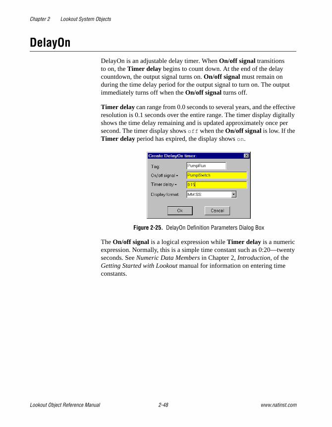
Chapter 2 Lookout System Objects
Lookout Object Reference Manual 2-48 www.natinst.com
DelayOnDelayOn is an adjustable delay timer. When On/off signal transitions to on, the Timer delay begins to count down. At the end of the delay countdown, the output signal turns on. On/off signal must remain on during the time delay period for the output signal to turn on. The output immediately turns off when the On/off signal turns off.
Timer delay can range from 0.0 seconds to several years, and the effective resolution is 0.1 seconds over the entire range. The timer display digitally shows the time delay remaining and is updated approximately once per second. The timer display shows off when the On/off signal is low. If the Timer delay period has expired, the display shows on.
Figure 2-25. DelayOn Definition Parameters Dialog Box
The On/off signal is a logical expression while Timer delay is a numeric expression. Normally, this is a simple time constant such as 0:20—twenty seconds. See Numeric Data Members in Chapter 2, Introduction, of the Getting Started with Lookout manual for information on entering time constants.
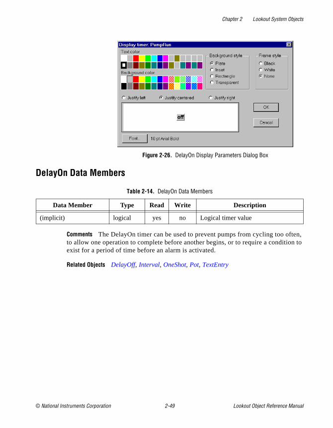
Chapter 2 Lookout System Objects
© National Instruments Corporation 2-49 Lookout Object Reference Manual
Figure 2-26. DelayOn Display Parameters Dialog Box
DelayOn Data Members
Comments The DelayOn timer can be used to prevent pumps from cycling too often, to allow one operation to complete before another begins, or to require a condition to exist for a period of time before an alarm is activated.
Related Objects DelayOff, Interval, OneShot, Pot, TextEntry
Table 2-14. DelayOn Data Members
Data Member Type Read Write Description
(implicit) logical yes no Logical timer value

Chapter 2 Lookout System Objects
Lookout Object Reference Manual 2-50 www.natinst.com
DerivativeDerivative can also be called a rate of change object—it calculates the rate of change of the incoming numeric input signal. You can use this class to calculate the rate at which a tank is filling or draining, or to convert a changing totalized flow value into a flow rate. The output units are in Input Units/Time Unit.
Figure 2-27. Derivative Definition Parameters Dialog Box
The previous example calculates the rate of change in the water level of a tank. Lookout polls the RTU connected to the tank level transmitter every 5 minutes, so this example uses the RTU update data member as the Update pulse for the Derivative object. Tanklevel is in feet and Time unit is 1 minute, so the output result is in feet per minute.
Input is the numeric expression you are monitoring for rate of change.
Update can be a logical expression or numeric constant. If you specify Update as a numeric constant, it creates an internal pulse timer with a pulse period of the specified time and a pulse duration of zero. See Numeric Data Members in Chapter 2, Introduction, of the Getting Started with Lookout manual for information on entering time constants. If you specify Update as a logical variable, the variable should pulse at the frequency you want to use.
The Update expression triggers the calculation of a new rate-of-change based on the Input value at the prior Update, and the current Input value. The current Input value is then stored as the prior Input value for the next calculation. The Update period should be greater than the refresh rate of the incoming signal; or if the Input is generated directly by external I/O, the update data member generated by the PLC object should be used. If theUpdate period is less than the Input refresh rate, the rate of change calculation fluctuates erratically between zero and a high value.
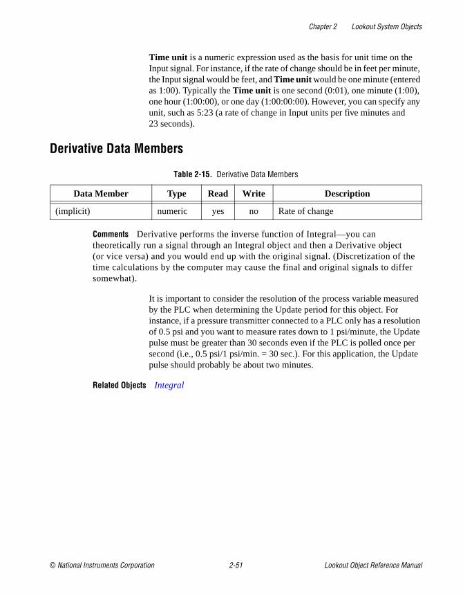
Chapter 2 Lookout System Objects
© National Instruments Corporation 2-51 Lookout Object Reference Manual
Time unit is a numeric expression used as the basis for unit time on the Input signal. For instance, if the rate of change should be in feet per minute, the Input signal would be feet, and Time unit would be one minute (entered as 1:00). Typically the Time unit is one second (0:01), one minute (1:00), one hour (1:00:00), or one day (1:00:00:00). However, you can specify any unit, such as 5:23 (a rate of change in Input units per five minutes and 23 seconds).
Derivative Data Members
Comments Derivative performs the inverse function of Integral—you can theoretically run a signal through an Integral object and then a Derivative object (or vice versa) and you would end up with the original signal. (Discretization of the time calculations by the computer may cause the final and original signals to differ somewhat).
It is important to consider the resolution of the process variable measured by the PLC when determining the Update period for this object. For instance, if a pressure transmitter connected to a PLC only has a resolution of 0.5 psi and you want to measure rates down to 1 psi/minute, the Update pulse must be greater than 30 seconds even if the PLC is polled once per second (i.e., 0.5 psi/1 psi/min. = 30 sec.). For this application, the Update pulse should probably be about two minutes.
Related Objects Integral
Table 2-15. Derivative Data Members
Data Member Type Read Write Description
(implicit) numeric yes no Rate of change
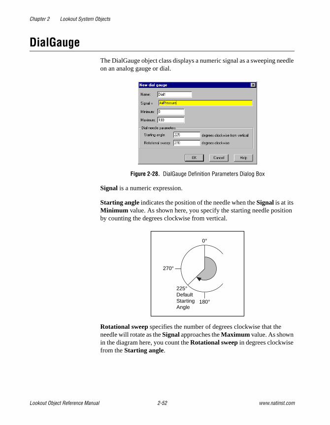
Chapter 2 Lookout System Objects
Lookout Object Reference Manual 2-52 www.natinst.com
DialGaugeThe DialGauge object class displays a numeric signal as a sweeping needle on an analog gauge or dial.
Figure 2-28. DialGauge Definition Parameters Dialog Box
Signal is a numeric expression.
Starting angle indicates the position of the needle when the Signal is at its Minimum value. As shown here, you specify the starting needle position by counting the degrees clockwise from vertical.
Rotational sweep specifies the number of degrees clockwise that the needle will rotate as the Signal approaches the Maximum value. As shown in the diagram here, you count the Rotational sweep in degrees clockwise from the Starting angle.
0°
180°
270°
225°DefaultStartingAngle

Chapter 2 Lookout System Objects
© National Instruments Corporation 2-53 Lookout Object Reference Manual
After you specify the DialGauge definition parameters, Lookout presents a display parameters dialog box, as shown here. You use this dialog box to specify needle color, thickness, and length.
Figure 2-29. DialGauge Display Parameters Dialog Box
Needle thickness defines how wide your needle will be. Thickness can range from one pixel (hairline) to 10 pixels wide.
Needle length specifies the length of the needle as a percent of the radius. At 30 percent, for example, only the outer tip of the needle is visible—you cannot see the part of the needle closest to the origin. At 100 percent, the needle extends the full radius of the circle.
0˚
180˚
270˚270˚
StartingAngle
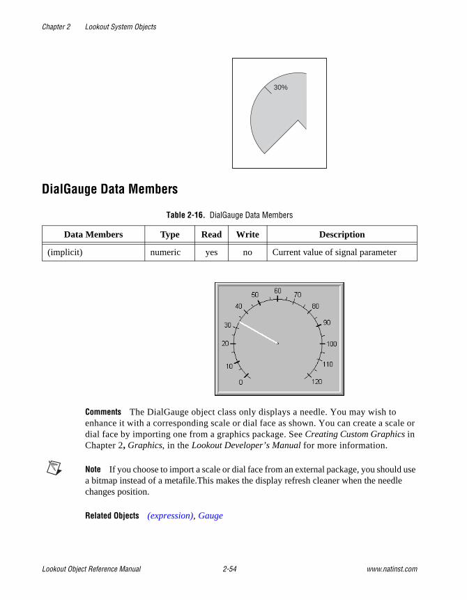
Chapter 2 Lookout System Objects
Lookout Object Reference Manual 2-54 www.natinst.com
DialGauge Data Members
Comments The DialGauge object class only displays a needle. You may wish to enhance it with a corresponding scale or dial face as shown. You can create a scale or dial face by importing one from a graphics package. See Creating Custom Graphics in Chapter 2, Graphics, in the Lookout Developer’s Manual for more information.
Note If you choose to import a scale or dial face from an external package, you should use a bitmap instead of a metafile.This makes the display refresh cleaner when the needle changes position.
Related Objects (expression), Gauge
Table 2-16. DialGauge Data Members
Data Members Type Read Write Description
(implicit) numeric yes no Current value of signal parameter
30%

Chapter 2 Lookout System Objects
© National Instruments Corporation 2-55 Lookout Object Reference Manual
ElapsedTime ElapsedTime is an elapsed time meter or “hour meter” that totals the amount of time the Enable expression is on. If Enable is the logical constant ON, the meter reflects the time since the process was started. If a Reset expression is specified, the meter resets to zero the moment Reset transitions from off to on. The display always shows the elapsed time, and is updated approximately once per second.
Figure 2-30. ElapsedTime Definition Parameters Dialog Box
ElapsedTime Data Members
Comments ElapsedTime meters are used primarily to record the amount of time that individual pieces of equipment have been running. It is also straightforward to set up an alarm that sounds when a particular device has been operating for a certain time and needs routine servicing. The plant operator could then perform the service and reset the ElapsedTime meter with a pushbutton.
ElapsedTime can also record the amount of time a particular device is operated each day and you can record the resulting time to a daily Spreadsheet which you can then use to automatically reset the meter after the data is permanently recorded.
Table 2-17. ElapsedTime Data Members
Data Member Type Read Write Description
(implicit) numeric yes no Total elapsed time—updated once per second, while meter is running

Chapter 2 Lookout System Objects
Lookout Object Reference Manual 2-56 www.natinst.com
EventEvent is a flexible and powerful object class you can use to define event messages that are triggered based on a user-defined logical expression. Lookout logs such events to the Citadel database and you can subsequently print and archive them. See Chapter 7, Logging Data and Events, in the Lookout Developer’s Manual for more information on logging events.
Figure 2-31. Typical Settings for an Event
When the result of the Trigger logical expression transitions from FALSE to TRUE, it logs the result of the Trigger hi text expression as an event in the EVENT.DAT file. When the results of the Trigger expression transitions from TRUE to FALSE, it logs the results of the Trigger lo text expression as an event.
Event Data Members
Comments For each event logged, Lookout records the date and time, the name of the user currently logged on, and the expression text.
Although event messages are shown for both Trigger hi text and Trigger lo text, you do not have to include text in both fields.
Table 2-18. Event Data Members
Data Member Type Read Write Description
none — — — Event objects do not have data members

Chapter 2 Lookout System Objects
© National Instruments Corporation 2-57 Lookout Object Reference Manual
(expression)Named expressions, shown as (expression)s, are flexible, powerful real-time calculators. They create and calculate the result of spreadsheet-style formulas that include a mixture of constants and signals from other objects. There are over fifty built-in functions that you use in expressions, including logical, mathematical, statistical, text and trigonometric functions. See Chapter 2, Expressions, in the Lookout Developer’s Manual for more information on expressions and expression functions.
Named expressions can be short and simple, or extremely complex with several signal inputs, function calls, and multiple levels of parentheses. A single expression may incorporate text, logical, and numeric calculations. The variable type returned by the outermost function or operator in the expression determines the signal type generated by the expression.
Figure 2-32. Create Expression Dialog Box
Note You typically use (expression) objects when you need to define a unique condition that is used multiple times throughout your application.
When you define an (expression) object (as opposed to inserting an intrinsic expression), you create a unique name for your expression and can therefore reference the output signal generated from the expression in other expressions or objects. Instead of defining the same expression in many places, you create it one time and use its name any time you need this expression.

Chapter 2 Lookout System Objects
Lookout Object Reference Manual 2-58 www.natinst.com
Note The expression may not express a condition.
Table 2-19. Expression Data Members
Data Member Type Read Write Description
(implicit) numeric, logical, or text
yes no Value of expression. The variable type returned by the outermost function or operator in the expression determines the signal type generated by the expression.

Chapter 2 Lookout System Objects
© National Instruments Corporation 2-59 Lookout Object Reference Manual
FlipflopFlipflop changes its logical output signal from on to off, or from off to on when the Input signal goes high. The output signal does not change when the signal goes low. Input is a logical expression.
Figure 2-33. Flipflop Definition Parameters Dialog Box
Flipflop Data Member
Comments Flipflop can be used to alternate the operation of two pumps, or when connected to a pushbutton, provides a pushbutton on/off control device.
Related Objects LatchGate
Table 2-20. Flipflop Data Member
Data Member Type Read Write Description
(implicit) logical yes no Current state
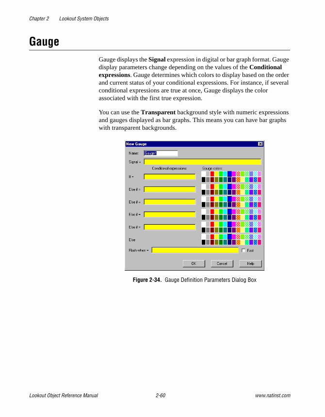
Chapter 2 Lookout System Objects
Lookout Object Reference Manual 2-60 www.natinst.com
GaugeGauge displays the Signal expression in digital or bar graph format. Gauge display parameters change depending on the values of the Conditional expressions. Gauge determines which colors to display based on the order and current status of your conditional expressions. For instance, if several conditional expressions are true at once, Gauge displays the color associated with the first true expression.
You can use the Transparent background style with numeric expressions and gauges displayed as bar graphs. This means you can have bar graphs with transparent backgrounds.
Figure 2-34. Gauge Definition Parameters Dialog Box
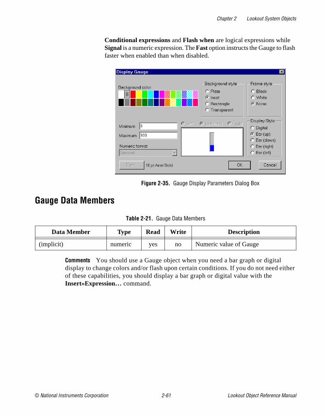
Chapter 2 Lookout System Objects
© National Instruments Corporation 2-61 Lookout Object Reference Manual
Conditional expressions and Flash when are logical expressions while Signal is a numeric expression. The Fast option instructs the Gauge to flash faster when enabled than when disabled.
Figure 2-35. Gauge Display Parameters Dialog Box
Gauge Data Members
Comments You should use a Gauge object when you need a bar graph or digital display to change colors and/or flash upon certain conditions. If you do not need either of these capabilities, you should display a bar graph or digital value with the Insert»Expression… command.
Table 2-21. Gauge Data Members
Data Member Type Read Write Description
(implicit) numeric yes no Numeric value of Gauge
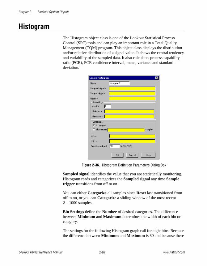
Chapter 2 Lookout System Objects
Lookout Object Reference Manual 2-62 www.natinst.com
HistogramThe Histogram object class is one of the Lookout Statistical Process Control (SPC) tools and can play an important role in a Total Quality Management (TQM) program. This object class displays the distribution and/or relative distribution of a signal value. It shows the central tendency and variability of the sampled data. It also calculates process capability ratio (PCR), PCR confidence interval, mean, variance and standard deviation.
Figure 2-36. Histogram Definition Parameters Dialog Box
Sampled signal identifies the value that you are statistically monitoring. Histogram reads and categorizes the Sampled signal any time Sample trigger transitions from off to on.
You can either Categorize all samples since Reset last transitioned from off to on, or you can Categorize a sliding window of the most recent 2 – 1000 samples.
Bin Settings define the Number of desired categories. The difference between Minimum and Maximum determines the width of each bin or category.
The settings for the following Histogram graph call for eight bins. Because the difference between Minimum and Maximum is 80 and because there

Chapter 2 Lookout System Objects
© National Instruments Corporation 2-63 Lookout Object Reference Manual
are eight bins, each class interval has a range of 10 (80/8 bins = 10). So bin1 contains sample values ranging from zero to less than 10; bin2 contains sample values ranging from 10 to less than 20, and so on.
This object always allocates two more bins than you request. These bins are used for accumulating samples less than the Minimum and greater than the Maximum . The lower bin is always data member f0 . The upper bin is fn+1 , where n=Number in Bin Settings.
In the following example, Bin0 (data member f0 ) contains all sample values less than Minimum and bin9 contains all sample values greater than or equal to Maximum.
Figure 2-37. Graph from Inserting Ten Numeric Expression Barcharts(Data Members f0 through f9 as Shown) and Two Scales
LSL and USL identify the lower and upper specification limits. These limits generally define the range of acceptable sample values. Histogram uses LSL and USL to calculate the process capability ratios (PCR andPCRk).
The Confidence level expresses the degree of certainty or probability that the actual value of PCR (the process capability ratio) falls within the confidence interval (that is, between PCRL and PCRU). A typical value is 95 percent. The lower the confidence level, the tighter the interval.
f1
f3
f4
f6 f8 f9f7f5
f2
f0
bin 1 bin 8
minimum maximum
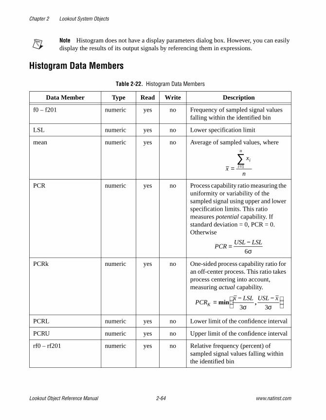
Chapter 2 Lookout System Objects
Lookout Object Reference Manual 2-64 www.natinst.com
Note Histogram does not have a display parameters dialog box. However, you can easily display the results of its output signals by referencing them in expressions.
Histogram Data Members
Table 2-22. Histogram Data Members
Data Member Type Read Write Description
f0 – f201 numeric yes no Frequency of sampled signal values falling within the identified bin
LSL numeric yes no Lower specification limit
mean numeric yes no Average of sampled values, where
PCR numeric yes no Process capability ratio measuring the uniformity or variability of the sampled signal using upper and lower specification limits. This ratio measures potential capability. If standard deviation = 0, PCR = 0. Otherwise
PCRk numeric yes no One-sided process capability ratio for an off-center process. This ratio takes process centering into account, measuring actual capability.
PCRL numeric yes no Lower limit of the confidence interval
PCRU numeric yes no Upper limit of the confidence interval
rf0 – rf201 numeric yes no Relative frequency (percent) of sampled signal values falling within the identified bin
x
x
n
i
i
n
= =∑
1
PCRUSL LSL= −
6σ
PCRx LSL USL x
K = − −
min ,
3 3σ σ

Chapter 2 Lookout System Objects
© National Instruments Corporation 2-65 Lookout Object Reference Manual
Comments The confidence interval is the range of values determined by the limits PCRL and PCRU.
Related Objects Average, Maximum, Minimum, Sample, XBarR
Related Functions Avg, Max, Min, Stdev, Stdevp, Sum, Var, VarpSee Chapter 1, Expressions, of the Lookout Developer’s Manual for more information on these functions.
samples numeric yes no Number of sampled signal values
sdev numeric yes no Sample standard deviation, where
USL numeric yes no Upper specification limit
variance numeric yes no Sample variance, where
Table 2-22. Histogram Data Members (Continued)
Data Member Type Read Write Description
( )σ =
−
−=∑ x x
n
i
i
n 2
1
1
( )σ2
2
1
1=
−
−=∑ x x
n
i
i
n

Chapter 2 Lookout System Objects
Lookout Object Reference Manual 2-66 www.natinst.com
HyperTrendA HyperTrend object displays a trend graph on a control panel. It plots any number of logical and numeric trend lines.
HyperTrends provide instant access to both real-time and historical data in a single graph. For each plot line, they combine both real-time and historical data into a seamless, contiguous trace of data. See Citadel Historical Database in Chapter 7, Logging Data and Events, in the Lookout Developer’s Manual.
Note There has been an important change in the way Lookout logs data to the Citadel database to be displayed on the HyperTrend object.
In Lookout 3.xx, creating a trend line in a HyperTrend object automatically logged the requested data to the database.
In Lookout 4, you must select the Log to historical database option in the Edit Database dialog box for any data you want to display in a HyperTrend object before you can display the data. This is because logging must be configured in a Lookout Server process, while trending is typically done in a separate Lookout client process.
You can log information by connecting to a symbolic link, but only if the data source the symbolic link represents has had the Log to historical database option selected.
You can use HyperTrends to pan and zoom both the X axis and the Y axis, enabling dynamic adjustment of the vertical and horizontal resolutions of each plot line on the graph. Using this feature, you can, for example, zoom into a particular area of focus on the trend.
The graph scrolls from right to left, plotting current, real-time signals at the right end of the graph.
The icon in the upper left of the display accesses a menu you can use to change the group of traces being plotted, activate the cursor, and start or stop scrolling. The arrow-shaped buttons make it easy for you to scroll the trend graph forward and back in time. It provides instant access to data that has scrolled off the left end of the graph (that is, historical data stored in the Citadel database).

Chapter 2 Lookout System Objects
© National Instruments Corporation 2-67 Lookout Object Reference Manual
The button bar includes scroll arrows, a cursor button, date, time, and a stop and go light. Use the scroll arrows to move back and forth through time-the bigger the arrow button you select, the further the trend jumps in time. The scroll arrows also function much like a horizontal slider. Click on them and slide the mouse left and right while holding down the mouse button. The further you slide the cursor from dead center, the faster the trend scrolls in that direction.
Use the date and time indicators to choose a specific month, day, year, hour, minute, or second. If you click on the lower part of the hour, for example, it jumps back in time by one hour.
If you click on the upper part of the hour, it jumps ahead by one hour.
It works the same way for month, day, year, minute and second.
The stop & go light on the button bar is either red or green. If the light is green, it indicates the far right edge of the trend window displays the current time.
When you scroll back in time or if you click on the light when it is green, it changes to red, indicating that the trend is temporarily frozen in time. The date and time appears in the button bar indicating the exact time at the far right edge of the trend window. As you scroll back and forth through time, the data and time changes accordingly.
If you click on the light when it is red, the trend jumps back to current time and starts scrolling while plotting real-time values.

Chapter 2 Lookout System Objects
Lookout Object Reference Manual 2-68 www.natinst.com
Note The Citadel database continues to log data no matter what state the HyperTrend is in. You do not lose any data when it is in "historical" mode (that is, when the HyperTrend is not scrolling in real-time).
When you click on the cursor button, a vertical cursor bar appears in the center of the graph along with an associated cursor dialog box. The dialog box indicates the value of each trend line at the current location of the cursor. As you drag the cursor bar left and right on the trend graph, the values in the pop-up change to reflect the new cursor location.
You can select how the trend line values are shown by choosing a format through the cursor control menu.
Figure 2-38. HyperTrend Cursor Dialog Box
Time indicates the current location of the cursor bar. The increment and decrement buttons beside the field move the cursor left and right in the trend graph. Choose the size of the incremental move by clicking on the desired portion of the date/time. The hour portion is selected in the previous example, so each time you click on the increment or decrement button, the cursor bar jumps ahead or back by an hour. It works the same way for any portion of the date and time.
Use the Find combo box to search for a break in the trend line, a signal peak or valley, or a specific value. For example, you can find the last instance in which a process control limit value was exceeded. To find the last time a trend line crossed a specific value, choose the desired trend line by clicking on it in the list box, select Value in the Find combo box, enter the desired value, and clock on the scroll back button.

Chapter 2 Lookout System Objects
© National Instruments Corporation 2-69 Lookout Object Reference Manual
To create a hypertrend object, choose Object»Create or right-click on a process in the object explorer and select New Object. Select HyperTrend . The following dialog box appears.
First you must create a group of trends. Double-click on the AddGroup button. The following dialog box appears.
Configuring the group sets the appearance of the HyperTrend object when it displays traces from that group. You can set different paper and grid colors for different groups to help operators distinguish between them.
Give your group a name that clearly identifies it. Be sure to set the Trend Width for the period of time you want under observation for that group. Graphs may have a default width, or time span, of anywhere from two seconds to four years. The default Trend Width in the example dialog box indicates a time span of 1:00:00 or one hour. See Numeric Data Members in Chapter 2, How Lookout Works, of the Getting Started with Lookout

Chapter 2 Lookout System Objects
Lookout Object Reference Manual 2-70 www.natinst.com
manual for more information on entering time constants. After creating the HyperTrend object, you can make the trend width adjustable by connecting a numeric signal to the TrendWidth data member.
Major increments specifies the number of heavy horizontal grid lines on a trend graph. This value is independent of the range of any trend expressions.
Minor increments specifies the number of light horizontal grid lines between the major increment grid lines on a trend graph. This value is independent of the range of any trend expressions.
After you create a group, you must add individual items. Right-click on the group you want to add a trace to. Select Add Item (or click on the Add Item button). The following dialog box appears.
Right-clicking in the URL field displays the object selection dialog box covering all the registered computers running Lookout on your network. Select the computer and process generating the value you want to display on your HyperTrend chart. See the URLs section for more information on this type of Lookout connection.
Minimum and Maximum set the scale for the trace on your display. If you are charting a logical data member, position and height set the base display line and the height of the trace from that point when your signal goes TRUE. Minimum is the bottom of the graph while Maximum is the top of the graph, regardless of the range of the expression. These settings create an imaginary vertical scale and affect each expression independently.
For example, take two numeric expressions, both of which range from 0 to 50. Set the Minimum and Maximum to 0 and 100 on the first expression, and -50 and 50 on the second. The first expression plots in the bottom half

Chapter 2 Lookout System Objects
© National Instruments Corporation 2-71 Lookout Object Reference Manual
of the chart while the second expression plots in the top half of the chart, even though they both fluctuate between 0 and 50.
This figure shows the imaginary scale of the first expression (where min. = 0 and max. = 100). Because the expression ranges from 0 to 50, it is plotted in the bottom half of the graph.
This figure shows the imaginary scale of the second expression (where min. = -50 and max. = 50). Because the expression ranges from 0 to 50, it is plotted in the top half of the graph.

Chapter 2 Lookout System Objects
Lookout Object Reference Manual 2-72 www.natinst.com
When both expressions are entered on a single trend graph, you get the following effect. Notice the custom scales at either end of the graph.
If you select Logical for the expression type, the minimum and maximum settings changes to Position and Height. These two values now represent a number between 0% and 100%, and determine the baseline location of the trend line and its unit height when the expression goes TRUE.
Use Insert»Scale to label the values being charted according to your minimum and maximum settings.
Comments HyperTrend objects access data from the Citadel database. Think of them as windows into your historical database. See Chapter 5, Developer Tour in the Getting Started with Lookout manual, and Chapter 7, Logging Data and Events, in the Lookout Developer’s Manual, for more information on specifying a point to be logged to the Citadel database.
HyperTrends are updated as quickly as once per second, depending on screen resolution, the size of the graph, and the trend width setting. Computers with slow display adapters may slow down considerably when you display a large trend graph. On slower computers with slow display cards (no graphics coprocessor), consider limiting the size of your HyperTrends to less than one fourth the screen size.
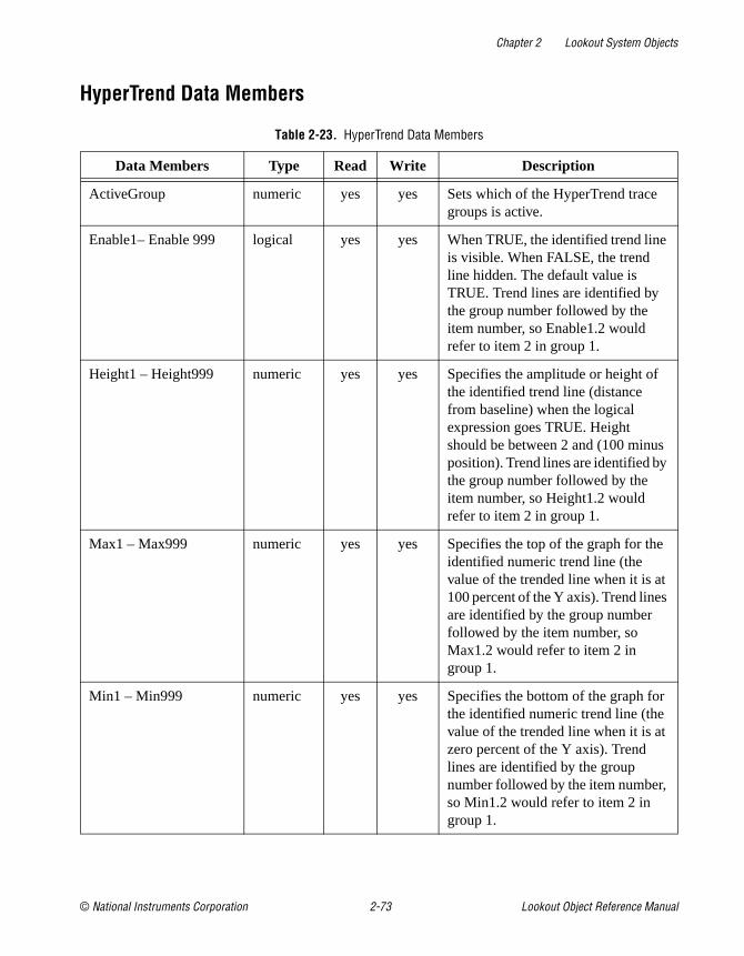
Chapter 2 Lookout System Objects
© National Instruments Corporation 2-73 Lookout Object Reference Manual
HyperTrend Data Members
Table 2-23. HyperTrend Data Members
Data Members Type Read Write Description
ActiveGroup numeric yes yes Sets which of the HyperTrend trace groups is active.
Enable1– Enable 999 logical yes yes When TRUE, the identified trend line is visible. When FALSE, the trend line hidden. The default value is TRUE. Trend lines are identified by the group number followed by the item number, so Enable1.2 would refer to item 2 in group 1.
Height1 – Height999 numeric yes yes Specifies the amplitude or height of the identified trend line (distance from baseline) when the logical expression goes TRUE. Height should be between 2 and (100 minus position). Trend lines are identified by the group number followed by the item number, so Height1.2 would refer to item 2 in group 1.
Max1 – Max999 numeric yes yes Specifies the top of the graph for the identified numeric trend line (the value of the trended line when it is at 100 percent of the Y axis). Trend lines are identified by the group number followed by the item number, so Max1.2 would refer to item 2 in group 1.
Min1 – Min999 numeric yes yes Specifies the bottom of the graph for the identified numeric trend line (the value of the trended line when it is at zero percent of the Y axis). Trend lines are identified by the group number followed by the item number, so Min1.2 would refer to item 2 in group 1.

Chapter 2 Lookout System Objects
Lookout Object Reference Manual 2-74 www.natinst.com
Converting Lookout 3.xx HyperTrends to Lookout 4If you convert a process created in a version of Lookout earlier than 4.0 which contains a HyperTrend object that is displaying a complex expression, Lookout automatically creates a named (expression) for the converted HyperTrend to chart. To maintain your legacy HyperTrend objects you must use or replace these (expression) objects.
Pos1 – Pos999 numeric yes yes Specifies the baseline location of the identified logical trend line. Baseline position should range should be 1–98. (pos1 is associated with trend line 1) Trend lines are identified by the group number followed by the item number, so Pos1.2 would refer to item 2 in group 1.
TrendWidth numeric yes yes Specifies the span of time that the X axis covers.
UseButtonBar logical yes yes When TRUE, the HyperTrend button bar becomes visible on the control panel. When FALSE, it is invisible. The default value is TRUE.
Visible logical yes yes When TRUE, the HyperTrend becomes visible on the control panel. When FALSE, it is invisible. The default value is TRUE.
Table 2-23. HyperTrend Data Members (Continued)
Data Members Type Read Write Description

Chapter 2 Lookout System Objects
© National Instruments Corporation 2-75 Lookout Object Reference Manual
IntegralIntegral is a totalizer—it totals the numeric Input signal. This class is typically used to total a measured flow rate.
Figure 2-39. Integral Definition Parameters Dialog Box
Input is the numeric expression that you want to totalize or integrate.
Update can be a logical expression or numeric constant. If you specify Update as a numeric constant, it creates an internal Pulse timer with a pulse period of the specified time and a pulse duration of zero. See Numeric Data Members in Chapter 2, How Lookout Works, of the Getting Started with Lookout manual for information on entering time constants. If you specify Update as a logical variable, the variable should pulse at the desired frequency.
The Update expression extrapolates an interim total based on the current total and the most recent Input value. The interim total is then sent out as the output. The total is calculated using the trapezoidal numeric integration technique, and the total is corrected any time the incoming signal is refreshed.
Time unit is a numeric expression used as the basis for unit time on the Input signal. For instance, if the Input rate is in units of gallons per minute, the Time unit should be entered as one minute (1:00) so the totalized flow is in gallons. Typically the Time unit is one second (0:01), one minute (1:00), one hour (1:00:00), or one day (1:00:00:00). However, you can specify any unit, such as 5:23 (a rate of change in Input units per five minutes and 23 seconds).
Reset is a logical expression that resets the totalizer value to zero upon transition from OFF to ON.

Chapter 2 Lookout System Objects
Lookout Object Reference Manual 2-76 www.natinst.com
Note Integral does not have a display parameters dialog box. You can easily display the result of the Integral output signal by referencing its data member in an expression.
Integral Data Members
Comments The Update pulse forces the calculated total to continue changing between Input signal updates. For example, if a remote RTU that is monitoring a flow rate is polled every ten minutes, the Update pulse could be set at five seconds so the operator can watch the totalized flow continue to change on the screen as an extrapolated value. The corrected totalized value is calculated any time the Input signal refreshes—in this case, every ten minutes.
If totalized values are logged to a spreadsheet on a daily basis, for example, and the total should be reset at the end of every day, use the update pulse generated by the Spreadsheet object to reset the total—this guarantees that the total is recorded before the totalizer is reset. The example on the previous page totalizes the hourly flow for permanent data logging by a spreadsheet object named HourlySheet. Notice that the spreadsheet update pulse HourlySheet.logged is used to reset the totalizer.
Related Objects Accumulator, Counter, Derivative
Table 2-24. Integral Data Members
Data Member Type Read Write Description
(implicit) numeric yes no Totalized value

Chapter 2 Lookout System Objects
© National Instruments Corporation 2-77 Lookout Object Reference Manual
InterpolateThe Interpolate object class performs a linear interpolation between a set of X,Y coordinate pairs to determine a corresponding output for any given input. A single Interpolate object can have up to 1,000 coordinate pairs. Although this object class can be used for any calculation requiring linear interpolation, it is especially useful for tank strapping applications.
Figure 2-40. Interpolate Definition Parameters Dialog Box
The following diagram visually depicts the basic functionality of the Interpolate object, and the set of coordinate pairs as entered.
Based on this graphical representation of the object, you can readily see how different X inputs give corresponding Y outputs. Also notice that an X input of 5.5 yields a Y output of 2.5—even though the last coordinate pair was (5,3). Lookout uses straight line extrapolation at both end points with a slope determined by the last two coordinate pairs.

Chapter 2 Lookout System Objects
Lookout Object Reference Manual 2-78 www.natinst.com
The New entry parameter fields enable adding, modifying and deleting Input(x) and Output(y) coordinate pairs. Input(x) and Output(y) are numeric parameters.
Input format and Output format define the numeric format of the Input(x) and Output(y) coordinate pairs displayed in the definition dialog box.
Sort order (inputs) specifies whether the dialog box lists X,Y coordinate pairs in Increasing or Decreasing order. The sort order has no bearing on output calculations or the values of the readable data members.
The Input(x) multiplier and the Output(y) multiplier are numeric expressions. These two parameters are useful for the more advanced calculations often found in tank strapping applications. They can be used for such things as temperature, pressure, density, and product correction factors. As their names imply, Lookout multiplies the corresponding Input/Output by the respective multiplier. If you specify an Input(x) multiplier , the object multiplies the input by the appropriate multiplier before calculating an interpolated output. If you specify an Output(y) multiplier , the object multiplies an interim output by the appropriate multiplier before calculating the final output value.
4
3
2
1
1 2 3 4 5 6
Inputs (X)
Out
puts
(Y
)
(0,1)
(1,2)
(2,3)
(4,4)
(5,3)
X,Y Coordinate Pairs

Chapter 2 Lookout System Objects
© National Instruments Corporation 2-79 Lookout Object Reference Manual
Step through a simple example using the preceding diagram to clarify this concept. Use an Input(x) multiplier of 1.5, and a Output(y) multiplier of 2. Assume the variable input is currently 2. The object first multiplies 2 by 1.5 to produce 3. It then uses the coordinate pairs to find the appropriate output value for an input of 3. As you can see, the interim output would be 3.5. Because you specified an output multiplier, it must first multiply 3.5 by 2 to give a final output of 7.
Situations may arise where you want multiple inputs going through a single Interpolate object, giving multiple respective outputs. Instead of creating an Interpolate object for each input, Lookout can connect multiple inputs to a single object and read their corresponding outputs. The inputs are writable data members (X0 – X999). For each input, there is a corresponding readable output (Y0 – Y999 respectively). The following diagram shows a numeric signal called TankLevel connected to an input, X0.
The Interpolate object now multiplies the X0 input by the Input(x) multiplier , find the two coordinate pair parameters that X0 falls between, interpolate, and multiply the interim output by the Output(y) multiplier , then send the resulting value to the Y0 readable data member.
Note The Interpolate object class does not have a display parameters dialog box. However, you can easily display the result of its output signals by referencing its data members in expressions.

Chapter 2 Lookout System Objects
Lookout Object Reference Manual 2-80 www.natinst.com
Interpolate Data Members
Comments If you want to interpolate another input using the same coordinate pair parameters and multipliers (that is, the same Interpolate object), connect to another input like X23, and read its corresponding output, Y23.
Because Xn and Yn data members are both readable and writable, the object can also act as a bi-directional interpolator. For example, you can connect a numeric signal to a Yn data member, and read the corresponding interpolated Xn data member. A real-world example of this could be a typical tank strapping problem. Normally, you would use a tank level as an input to X0, and read the interpolated output Y0 as the corresponding tank volume. Hence you begin with a level and end up with a volume. However, you might also be monitoring the volume and would like to use that value to calculate a corresponding level. In that case, you might want the Interpolate object to be bi-directional, which it is. If Y0 ever changes, the object divides Y0 by the Output(y) multiplier , interpolate between the two closest Output(y) parameters, calculate a corresponding input value based on the two closest Input(x) parameters, divide it by the Input(x) multiplier , and send the resulting value to the X0 data member.
Table 2-25. Interpolate Data Members
Data Members Type Read Write Description
X0 – X999 numeric yes yes Input value
Y0 – Y999 numeric yes yes Output value. For a given input, Xn, the object outputs the result of the interpolation as a corresponding Yn value.

Chapter 2 Lookout System Objects
© National Instruments Corporation 2-81 Lookout Object Reference Manual
IntervalInterval is an adjustable delay timer. When On/off signal transitions to on, its output turns on and the Timer delay begins to count down. At the end of the delay countdown, the output signal turns OFF. If On/off signal is dropped at any time, the output signal turns OFF, and the timer is reset.
Timer delay can range from 0.0 seconds to several years, and the effective resolution is 0.1 seconds over the entire range. The timer display digitally shows the time delay remaining. It is updated approximately once per second. If the On/off signal is low, or the time delay period has expired, the timer display shows OFF.
Figure 2-41. Interval Definition Parameters Dialog Box
The On/off signal is a logical expression while Timer delay is a numeric expression. Normally, this is a simple time constant such as 0:20 (twenty seconds). See Numeric Data Members in Chapter 2, How Lookout Works, of the Getting Started with Lookout manual for information on entering time constants.
Figure 2-42. Interval Display Parameters Dialog Box

Chapter 2 Lookout System Objects
Lookout Object Reference Manual 2-82 www.natinst.com
Interval Data Members
Comments The Interval timer can be used to enforce a maximum run time for a pump.
Related Objects DelayOff, DelayOn, OneShot, Pot, TextEntry
Table 2-26. Interval Data Members
Data Member Type Read Write Description
(implicit) logical yes no Logical timer value

Chapter 2 Lookout System Objects
© National Instruments Corporation 2-83 Lookout Object Reference Manual
JunctionJunction receives up to nine numeric values, each of which could be the result of a complex numeric expression. It outputs the value of the last Additional input that changed (event driven). Notice, however, that it will not output a value until the Initializing input has changed. After that, any change in any input is immediately output.
Figure 2-43. Junction Definition Parameters Dialog Box
Junction Data Members
Comments Junction is a unique class that should be used only in rare circumstances.
Table 2-27. Junction Data Members
Data Member Type Read Write Description
(implicit) numeric yes no The value of the input that most recently changed

Chapter 2 Lookout System Objects
Lookout Object Reference Manual 2-84 www.natinst.com
$Keyboard$Keyboard is a global object. Its data members represent the keyboard function keys. Unlike other object classes in which you can create several objects of the same class, you cannot create or delete $Keyboard objects, but you can use the one supplied.
You can use the $Keyboard global object to perform such functions as calling a particular control panel, activating a batch sequence, or acknowledging alarms by pressing a key.
Think of $Keyboard data members (which represent function keys on the keyboard) as Lookout pushbuttons. Just as you can connect a pushbutton to the activate data member of a panel, you can also connect a $Keyboard data member to the activate data member of a panel. Such a connection is shown in the following illustration.
Figure 2-44. Edit Connections Dialog Box
The logical expression, $Keyboard.F1 calls up Panel1 any time a user presses the F1 key on the keyboard. Similar connections could be made to other panels. You can easily connect a different panel to each function key.

Chapter 2 Lookout System Objects
© National Instruments Corporation 2-85 Lookout Object Reference Manual
Just as easily, you can connect a function key to a batch process trigger. When the key is pressed, (that is, when the $Keyboard data member goes TRUE) the batch is activated—reading batch ingredients from a recipe object, opening and closing valves, starting mixers, bottling finished material, and so on.
You might also connect a function key to $Alarm.ack . This would enable users to acknowledge alarms through a single keystroke.
$Keyboard Data Members$Keyboard has 72 readable data members. Each data member represents a unique key sequence, described in the following table.
Table 2-28. $Keyboard Data Members
Data Member Type Read Write Description
Ctrl-F1 - Ctrl-F24 logical yes no Each of these 24 data members represent a function key, F1 – F24—when pressed in conjunction with the Ctrl key. A given data member returns logical TRUE when the Ctrl key and function key are pressed together and FALSE when the keys are released.
F1 - F24 logical yes no Each of these 24 data members represent a function key, F1 – F24. A given data member returns a logical TRUE when its associated function key is pressed and FALSE when the key is released.
Shift-F1 - Shift-F24 logical yes no Each of these 24 data members represent a function key, F1 – F24—when pressed in conjunction with the Shift key. A given data member returns logical TRUE when the Shift key and function key are pressed together and FALSE when the keys are released.

Chapter 2 Lookout System Objects
Lookout Object Reference Manual 2-86 www.natinst.com
Comments $Keyboard function keys are global in nature. Any time F1 is pressed, the $keyboard.F1 signal goes TRUE—regardless of what panel the user is looking at. If you want a function key to be unique from one control panel to the next, use the Panel object class function key data member. See Panel object class definition for more information.
Related Objects L3Pushbutton, Pushbutton

Chapter 2 Lookout System Objects
© National Instruments Corporation 2-87 Lookout Object Reference Manual
L3PotL3Pot is a potentiometer that you use to change numeric setpoint values. You can display pots on a control panel as a knob, vertical slider, horizontal slider, increment/decrement pushbuttons, or digital entry. You can also use pots as multiple-position switches.
If you change the background color of a panel and add a Pot object displayed as a slider, its color is always gray. To change the background color of a Pot to match your panel, select the Pot object, then pick Change»Background Color from the menu.
Figure 2-45. L3Pot Definitions Parameters Dialog Box
Minimum is the lowest value signal the Pot will generate.
Maximum is the highest value signal the Pot will generate.
Resolution is the smallest increment of change, or detent spacing the Pot supports.
Position source determines where the value of the Pot resides. Local indicates the value of the Pot lies within the object itself—on the control panel.

Chapter 2 Lookout System Objects
Lookout Object Reference Manual 2-88 www.natinst.com
Remote pots get their values from a remote source, often the register on a controller they are connected to. Adjusting the Pot changes the value in the register, and changing the value in the register adjusts the Pot. In effect, the Pot is tracking a remote value. This is especially useful when you want to prevent Lookout from changing the value of setpoints or registers upon initial startup, or reconnection of lost communication. When you use this style Pot you are creating a kind of looped signal. Half the loop is formed when you connect the controller register to the Pot with the Position expression, while the second half is formed when you connect the Pot output signal to the controller register. Position is a numeric expression. Do not forget to complete the second half of the loop with the Object»Edit Connections… command.
Much like Remote Pots, DDE (Dynamic Data Exchange) Pots get their values from a remote source. This could be a cell in a spreadsheet, another DDE aware application, or a second copy of Lookout running on the network. The last DDE parameters used on any object automatically become the default values for any new DDE object. See Chapter 5, Dynamic Data Exchange, of the Lookout Developer’s Manual for more information on Service, Topic, and Item parameters.
Control security level specifies the minimum security level operators must have to gain access to this individual object, and thus control it.
The Log events option creates a permanent audit trail for the object—who did what and when. All adjustments of the Pot are logged to disk, including the time of the adjustment, the operator account name, and what adjustment was made. See Chapter 7, Logging Data and Events, in the Lookout Developer’s Manual for more information on event logging.
Figure 2-46. L3Pot Display Parameters Dialog Box

Chapter 2 Lookout System Objects
© National Instruments Corporation 2-89 Lookout Object Reference Manual
Note You can modify the background color on vertical and horizontal sliders with the Change»Background color… menu command. You can modify the font and font color of digital pots using Change commands.
L3Pot Data Members
Table 2-29. L3Pot Data Members
Data Member Type Read Write Description
(implicit) numeric yes no Current value
decrement logical no yes When this data member value transitions from FALSE to TRUE, the implicit value of the Pot object decreases by the Pot Resolution amount.
enable logical no yes If TRUE (the default), enables DDE. If FALSE, disables DDE. The default value is on. This input is ignored for non-DDE TextEntry objects.
enterValue logical no yes Under specific circumstances, when this value transitions from FALSE to TRUE, pops up a Enter new value dialog box for an operator to use in entering a value for the pot. See the note following the table for more detailed information.
The enterValue data member is designed for use under unusual circumstances, in particular when pointing devices are not available on a computer running Lookout. Because of its unusual operation, this data member should not be used unless it is necessary for hardware reasons.

Chapter 2 Lookout System Objects
Lookout Object Reference Manual 2-90 www.natinst.com
Note When the enterValue input transitions from FALSE to TRUE, and if the Pot is visible, if Lookout is not in edit mode, and if the Pot has at least one digital display,
The Enter new value dialog box pops up so an operator can input a value, just as if he had clicked on the digital display.
The numeric format and position used for the dialog box are based on the digital display for a pot.
Even if the panel containing the Pot digital display is inactive, the Enter new value dialog box will pop up. You can prevent this by predicating the enterValue input on the panel’s active data member.
Comments Potentiometers are one of the most common control objects used in process controls. Using Pots, a plant operator can make setpoint changes with the mouse. L3Pots also work well as HOA switches. To create an HOA switch with a Pot, specify the minimum as 1, the maximum as 3, and the resolution as 1.
The increment and decrement data members enable quick connection of pot objects to $Keyboard and Panel function keys, and screen Pushbuttons. These are often used to control Pot objects when Lookout is running on an industrial PC platform that has restricted or no mouse functionality.
increment logical no yes When this data member value transitions from FALSE to TRUE, the implicit value of the Pot object increases by the Resolution amount.
visible logical no yes When FALSE, the Pot object cannot be seen on the display panel. When TRUE, the Pot can be seen and controlled.
Table 2-29. L3Pot Data Members (Continued)
Data Member Type Read Write Description

Chapter 2 Lookout System Objects
© National Instruments Corporation 2-91 Lookout Object Reference Manual
L3PushbuttonL3Pushbutton generates a logical signal for receipt by other objects. A pushbutton changes state when you position the cursor over it and press the mouse button, trackball, touchscreen, or space bar. The pushbutton remains depressed and the output signal remains high until you release the button. If a Verify on message is defined, the operator must first acknowledge the message, then the output signal goes high, but only momentarily.
Figure 2-47. L3Pushbutton Definitions Parameters Dialog Box
Button text displays the specified text on the pushbutton.
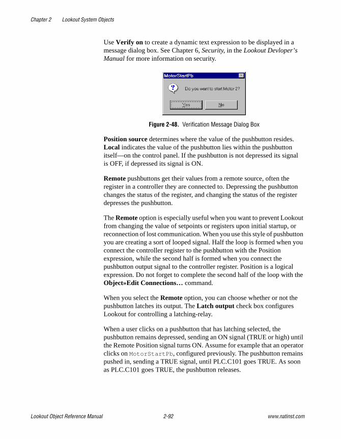
Chapter 2 Lookout System Objects
Lookout Object Reference Manual 2-92 www.natinst.com
Use Verify on to create a dynamic text expression to be displayed in a message dialog box. See Chapter 6, Security, in the Lookout Devloper’s Manual for more information on security.
Figure 2-48. Verification Message Dialog Box
Position source determines where the value of the pushbutton resides. Local indicates the value of the pushbutton lies within the pushbutton itself—on the control panel. If the pushbutton is not depressed its signal is OFF, if depressed its signal is ON.
Remote pushbuttons get their values from a remote source, often the register in a controller they are connected to. Depressing the pushbutton changes the status of the register, and changing the status of the register depresses the pushbutton.
The Remote option is especially useful when you want to prevent Lookout from changing the value of setpoints or registers upon initial startup, or reconnection of lost communication. When you use this style of pushbutton you are creating a sort of looped signal. Half the loop is formed when you connect the controller register to the pushbutton with the Position expression, while the second half is formed when you connect the pushbutton output signal to the controller register. Position is a logical expression. Do not forget to complete the second half of the loop with the Object»Edit Connections… command.
When you select the Remote option, you can choose whether or not the pushbutton latches its output. The Latch output check box configures Lookout for controlling a latching-relay.
When a user clicks on a pushbutton that has latching selected, the pushbutton remains depressed, sending an ON signal (TRUE or high) until the Remote Position signal turns ON. Assume for example that an operator clicks on MotorStartPb , configured previously. The pushbutton remains pushed in, sending a TRUE signal, until PLC.C101 goes TRUE. As soon as PLC.C101 goes TRUE, the pushbutton releases.

Chapter 2 Lookout System Objects
© National Instruments Corporation 2-93 Lookout Object Reference Manual
Much like Remote pushbuttons, DDE (Dynamic Data Exchange) pushbuttons get their values from a remote source. This could be a cell in a spreadsheet, another DDE aware application, or a second copy of Lookout running on the network. See Chapter 5, Dynamic Data Exchange, in the Lookout Developer’s Manual for information on Service, Topic, and Item parameters.
Control security level specifies the minimum security level operators must have to gain access to this individual object, and thus control it. See Chapter 6, Security, in the Lookout Developer’s Manual for more information on security.
The Log events option creates a permanent audit trail for the object—who did what and when. Any depression of the pushbutton is recorded to disk, including the time the button was depressed, and the operator’s account name. See Chapter 7, Logging Data and Events, in the Lookout Developer’s Manual for more information on logging events.
Figure 2-49. L3Pushbutton Display Parameters Dialog Box

Chapter 2 Lookout System Objects
Lookout Object Reference Manual 2-94 www.natinst.com
L3Pushbutton Data Members
Table 2-30. L3Pushbutton Data Members
Data Members Type Read Write Description
(implicit) logical yes no Value of object (TRUE when button is depressed)
enable logical no yes If TRUE (the default), enables DDE. If FALSE, disables DDE. The default value is on. This input is ignored for non-DDE TextEntry objects.
visible logical no yes When FALSE, the pushbutton cannot be seen on the display panel. When TRUE, the button can be seen and controlled.

Chapter 2 Lookout System Objects
© National Instruments Corporation 2-95 Lookout Object Reference Manual
L3SwitchL3Switch generates a logical signal for receipt by other objects. Switches change state when you click on them with a mouse button, trackball, touchscreen, or space bar on your keyboard.
Figure 2-50. L3Switch Definition Parameters Dialog Box
Use Action verification messages to create dynamic text expressions to be displayed in message dialog boxes. See Chapter 6, Security, in the Lookout Developer’s Manual for more information on security.
Figure 2-51. Verification Message Dialog Box
Position source determines where the value of the switch resides. Local indicates the value of the switch lies within the object itself—on the control panel. If the switch is up the signal is ON, if down the signal is OFF.
Remote switches get their values from a remote source, often the register on a controller they are connected to. Flipping the switch changes the status of the register, and changing the status of the register flips the switch.
The Remote option is especially useful when you want to prevent Lookout from changing the value of setpoints or registers upon initial startup, or reconnection of lost communication. When you use this style switch, you are creating a sort of looped signal. Half the loop is formed when you

Chapter 2 Lookout System Objects
Lookout Object Reference Manual 2-96 www.natinst.com
connect the controller register to the switch with the Position expression, while the second half is formed when you connect the switch output signal to the controller register. Notice Position is a logical expression. Do not forget to complete the second half of the loop with the Object»Edit Connections… command.
Much like Remote switches, DDE (Dynamic Data Exchange) switches get their values from a remote source. This could be a cell in a spreadsheet, another DDE aware application, or a second copy of Lookout running on the network. See Chapter 5, Dynamic Data Exchange, in the Lookout Developer’s Manual for more information on Service, Topic, and Item parameters.
Control security level specifies the minimum security level operators must have to gain access to this individual object, and thus control it.
The Log events option creates a permanent audit trail for the object—who did what and when. All adjustments of the switch are logged to disk, including the time the switch was flipped, the operator’s account name, and the direction the switch was flipped. See Chapter 7, Logging Data and Events, in the Lookout Developer’s Manual for more information on event logging.
You can replace the standard switch types with custom graphic symbols. If you decide to use custom graphics, you must specify both symbol parameters, On and Off . See Chapter 2, Graphics, in the Lookout Developer’s Manual for more information on creating custom graphic symbols and the use of Transparent pixels.

Chapter 2 Lookout System Objects
© National Instruments Corporation 2-97 Lookout Object Reference Manual
L3Switch Data Members
Comments If a switch with more than two positions is needed, use a Radiobutton object instead.
Related Objects L3Pushbutton, L3Pot, Pushbutton, Pot
Table 2-31. L3Switch Data Members
Data Members Type Read Write Description
(implicit) logical yes no L3Switch Position
enable logical no yes If TRUE (the default), enables DDE. If FALSE, disables DDE. The default value is ON. This input is ignored for non-DDE L3TextEntry objects.
visible logical no yes When FALSE, the switch object cannot be seen on the display panel. When TRUE, the switch can be seen and controlled.

Chapter 2 Lookout System Objects
Lookout Object Reference Manual 2-98 www.natinst.com
L3TextEntryWith L3TextEntry you can manually enter textual notes with the keyboard. These notes may contain any combination of numeric and alphanumeric characters; however, the result of your entry is converted to a text value. Just like any other text expression in Lookout, your note can be logged to disk, connected to other data members that accept text signals, and so on. The note is saved and displayed as a single line entry—you cannot embed carriage returns into the message.
Figure 2-52. TextEntry Parameters Dialog Box
Entry prompt is the text that appears at the top of the text entry dialog box when an operator selects the text entry pushbutton.
Text source determines where the user-entered text resides. Local indicates the user-entered text lies within the object itself—on the control panel.
Remote indicates that the user-entered text resides in a remote source, such as a text expression or another TextEntry object.
Much like Remote TextEntry objects, DDE TextEntry objects get their values from a remote source. This is the option you use to tie the text to a cell in a spreadsheet, a database lookup table, or any DDE aware

Chapter 2 Lookout System Objects
© National Instruments Corporation 2-99 Lookout Object Reference Manual
application—including a second copy of Lookout running on the network. See Chapter 5, Dynamic Data Exchange, in the Lookout Developer’s Manual for more detailed information on Service, Topic and Item.
Note The last DDE parameters used on any object automatically become the default values for any new DDE object.
Control security level specifies the minimum security level operators must have to gain access to this individual object, and thus control it.
The Log events option creates a permanent audit trail for the object—who did what and when. When selected, all text entries in this object are logged to disk. Each entry includes the time of the entry, the operator’s account name, and what entry was made. See Chapter 7, Logging Data and Events, in the Lookout Developer’s Manual for more information on event logging.
Lookout presents the following display parameters dialog box after you define the object. It lets you define the text font and presentation style.
Figure 2-53. TextEntry Display Parameters Dialog Box

Chapter 2 Lookout System Objects
Lookout Object Reference Manual 2-100 www.natinst.com
L3TextEntry Data Members
Table 2-32. L3TextEntry Data Members
Data Members Type Read Write Description
(implicit) text yes no Current, user-entered text
enable logical no yes If TRUE (the default), enables DDE. If FALSE, disables DDE. The default value is ON. This input is ignored for non-DDE TextEntry objects.

Chapter 2 Lookout System Objects
© National Instruments Corporation 2-101 Lookout Object Reference Manual
LatchGateLatchGate is latched on and off by two incoming signals. It retains the state of the signal that most recently went high, regardless of the state of the other signal. When the Turn Off signal transitions from OFF to ON, the LatchGate output goes OFF until the Turn On signal transitions from OFF to ON. The output signal does not change when either incoming signal transitions from ON to OFF. Both Turn Off and Turn On are logical expressions.
Figure 2-54. LatchGate Definition Parameters Dialog Box
LatchGate Data Members
Comments Two pushbuttons connected to the Turn On and Turn Off expressions of a LatchGate create pushbutton start/stop controls for a pump or other device.
Related Objects Flipflop
Table 2-33. LatchGate Data Members
Data Member Type Read Write Description
(implicit) logical yes no Logical output signal value

Chapter 2 Lookout System Objects
Lookout Object Reference Manual 2-102 www.natinst.com
LoaderUse the Lookout Loader to load or unload a Lookout process in response to a logical trigger. Using a Loader object in conjunction with a Monitor object is how you create failover redundancy with Lookout. See Chapter 10, Redundancy, in the Lookout Developer’s Manual for more information on redundancy.
You may notice that the information in the State Information and Citadel Database sections of this dialog box are the same as those areas in the Create Process dialog box and, in the case of the Citadel Database section, the System Options dialog box. Just as the Citadel Database section of the Create Process dialog box overrides the system database location settings for a particular process, any settings you make in the Loader object for database location or saving of state files override both system defaults and whatever settings you may have made when you created the process being loaded.
Process Name is the name that the process runs under when you open the Process File. You can use a process name other than the one used when the process file loaded was created.
Process File is the name of the file this Loader object will load when activated. You must enter a complete path to the file. You can specify a file

Chapter 2 Lookout System Objects
© National Instruments Corporation 2-103 Lookout Object Reference Manual
from another computer on your network, but you must map the location on the remote computer as a network drive on your own computer first.
The State Information section of this dialog box lets you set where Lookout saves state files for the process just loaded, and under what name the files are saved.
Select Save State File with Process File to save the state file in the location where the process file was opened.
Select Save State File in Lookout Folder to save the state file in the Lookout folder of the copy of Lookout your are currently running. The state file name is the same as the process name.
Select the Save Standby State File checkbox to save one or more extra copies of the state file in a location of your choosing. Enter a complete path, including state file name, to each location you want to save a state file. If you are saving the state file to more than one backup or alternative location, separate the paths with the vertical bar (| ) operator symbol.
Check the Save State File(s) every NNNN (1-1440) minutes option to set the frequency with which Lookout saves the state file. The Lookout default is 60 minutes.
The Citadel Database section sets the location of the Citadel database that Lookout logs data to for the process you load. If you check the Use Default Values checkbox, Lookout uses the default location set in the System Options dialog box of any instance of Lookout running the process.
If you enter a computer name and a path on that computer to a specific folder, Lookout logs data to that location on that computer, no matter what computer is running the process.
To designate a specific computer and path for your process to log data to, enter the fully qualified network name for the target computer in the Computer Name field, and the complete path to the target database directory in the Citadel Database Folder field.
Load is the logical signal you use to activate the Loader and load the process.
Unload is the logical signal you use to activate the Loader and unload the process you loaded earlier.

Chapter 2 Lookout System Objects
Lookout Object Reference Manual 2-104 www.natinst.com
The Loader can only load one process at a time, and can only load a process to run inside the instance of Lookout currently running the process that contains the Loader.
To load multiple processes with one trigger, you must use multiple Loader objects.
Loader Data Members
Table 2-34. Loader Data Members
Data Member Type Read Write Description
SaveWithProcess logical yes no When TRUE, Lookout saves a state file in the same location as the process file it contains the state for.
DatabaseComputer text yes no Sets the computer on which Lookout saves Citadel database files.
DatabaseFolder text yes no Sets the folder in which Lookout saves Citadel database files.
Failure logical yes no Monitor this data member to be alerted if a load attempt fails.
Failuretext text yes no Returns the reason for a failure to load the process designated by the loader.
Load logical yes yes Triggers the loader to load the designated process file.
ProcessFile text yes no Name of the process the loader loads when activated.
ProcessName text yes no Specifies the process name a loaded process runs under.
SavePeriod numeric yes no Sets how often, in minutes, that Lookout saves the state file for the loaded process.
SaveWithLookout logical yes no When TRUE, Lookout saves the state file in the Lookout directory, using ProcessName as the name for the state file as well.

Chapter 2 Lookout System Objects
© National Instruments Corporation 2-105 Lookout Object Reference Manual
Loader Error MessagesLoad: No process file specified
Specify a process file in the ProcessFile field.
Load: No process name specified
Name your process in the ProcessName field.
Load: Process already exists: loadername.processname
The process specified by your Loader object is already running under that name in this instance of Lookout. Only one process may run under each process name.
Load: No state file specified
You must specify state file information for any process you load with a Loader object.
Load: Invalid process name
You have chosen an invalid process name. See the Object Names section in Chapter 4, Using Lookout, of your Getting Started With Lookout manual for detailed information on valid Lookout process and object names.
Load: Invalid database computer name
The computer name you have entered in the ComputerName field is not registered as being a part of your Lookout network. Check the spelling of the name or register the computer through the Lookout Object Explorer or the Lookout Connection Browser.
Load: Invalid database folder
Check the path you have entered in the Citadel Database Folder field to make sure the path you entered does exist on the computer specified in the ComputerName field.
StandbyFile text yes no Complete path to the location in which you want Lookout to save copies of the state file.
Unload logical yes yes Triggers the loader to unload the designated process.
Table 2-34. Loader Data Members
Data Member Type Read Write Description

Chapter 2 Lookout System Objects
Lookout Object Reference Manual 2-106 www.natinst.com
Load: Can't open process file processfilename
Lookout was unable to open the file processfilename . Check to see that the file exists in the specified location and has not been corrupted.
Unload: No process name specified
Enter the name of the process you want to unload in the Process Name field.
Unload: Process not found
Lookout must be running a process with the name specified in the Process Name field for the Loader to unload a process. If no process with the specified name is running when the Loader attempts to unload a process, Lookout returns this error message.

Chapter 2 Lookout System Objects
© National Instruments Corporation 2-107 Lookout Object Reference Manual
MaximumMaximum actively calculates the maximum value of Data over time. Maximum is only active when the Enable expression is TRUE. It resets to zero when the Reset expression transitions from OFF to ON. Maximum also maintains an array of up to 35 previous maximum values. If Enable is left blank, the object always actively calculates the maximum. Data is a numeric expression while Reset and Enable are logical expressions.
Figure 2-55. Maximum Configuration Parameters Dialog Box
Note Maximum does not have a display parameters dialog box. However, you can easily display Maximum by referencing it in an expression.
Maximum Data Members
Table 2-35. Maximum Data Members
Data Members Type Read Write Description
(implicit) numeric yes no Current maximum value
1 – 35 numeric yes no Previous maximum values. Signal 1 is the most recent prior maximum since the Reset expression went high.
DataReset logical no yes Upon transition from FALSE to TRUE, resets to zero all data members—including the current maximum value and all previous maximum values.

Chapter 2 Lookout System Objects
Lookout Object Reference Manual 2-108 www.natinst.com
Comments The Reset interval could be a regular pulse interval created by a TimeOfxxxx timer, so that the pulse is synchronized to the top of the hour or day. For example, if you want to calculate the daily maximum flow rate, use the output signal from a TimeOfDay timer or a daily Spreadsheet object to reset the maximum calculation at the beginning of each day.
Related Objects Average, Minimum, Sample, SampleText

Chapter 2 Lookout System Objects
© National Instruments Corporation 2-109 Lookout Object Reference Manual
MinimumMinimum actively calculates the minimum level of Data over time. Minimum is only active when the Enable expression is TRUE. It resets to zero when the Reset expression transitions from OFF to ON. Minimum also maintains an array of up to 35 previous minimum values. If Enable is left blank, the object is always actively calculating the minimum. Data is a numeric expression while Reset and Enable are logical expressions.
Figure 2-56. Minimum Configuration Parameters Dialog Box
Note Minimum does not have a display parameters dialog box. You can easily display the Minimum value referencing it an expression.
Minimum Data Members
Table 2-36. Minimum Data Members
Data Members Type Read Write Description
(implicit) numeric yes no Current minimum value
1 – 35 numeric yes no Previous minimum values. Signal 1 is the most recent prior minimum since the Reset expression went high.
DataReset logical no yes Upon transition from FALSE to TRUE, resets to zero all data members—including the current minimum value and all previous minimum values.

Chapter 2 Lookout System Objects
Lookout Object Reference Manual 2-110 www.natinst.com
Comments The Reset interval could be a regular pulse interval created by a TimeOfxxxx timer, so that the pulse is synchronized to the top of the hour or day. For example, if you want to calculate the daily minimum flow rate, use the output signal from a TimeOfDay timer or a daily Spreadsheet object to reset the minimum calculation at the beginning of each day.
Related Objects Average, Maximum, Sample, SampleText

Chapter 2 Lookout System Objects
© National Instruments Corporation 2-111 Lookout Object Reference Manual
MonitorThe Lookout Monitor object is integral to Lookout redundancy. The Monitor object maintains a connection with a data member in any process you want to watch from another computer or process. If the data flow from that source stops, the Monitor signals the halt, allowing you to respond.
Using a Monitor object in conjunction with a Loader object is how you create failover redundancy with Lookout. See Chapter 10, Redundancy, in the Lookout Developer’s Manual for more information on redundancy.
In the Output goes high field enter a data member in the process you want to monitor. If the data quality of that expression goes bad for more than the number you enter in the seconds field, the monitor goes high (TRUE), letting you know there is a problem with the process.
Monitor Data Members
Table 2-37. Monitor Data Members
Data Member Type Read Write Description
(implicit) logical yes no Goes TRUE when the data member the Monitor is watching cannot be accessed after a specified length of time.
timeout numeric yes no The length of time in seconds that the data member being monitored must be unavailable before the Monitor goes TRUE.

Chapter 2 Lookout System Objects
Lookout Object Reference Manual 2-112 www.natinst.com
MultistateMultistate displays different graphics on a control panel as dictated by the values of Conditional expressions. You can use up to six Graphic files, but at least one is required. Multistate determines which graphic to display based on the order and current status of your Conditional expressions. If several Conditional expressions are true at once, Multistate displays the graphic associated with the first true expression.
Figure 2-57. Multistate Configuration Parameters Dialog Box
Conditional expressions must result in logical values (TRUE or FALSE). See the Animator section for more information about constructing logical statements. Double-click in a Graphic file box to select the graphic you want to use.
Multistate Data Members
Table 2-38. Multistate Data Members
Data members Type Read Write Description
none — — — Multistate objects do not have data members

Chapter 2 Lookout System Objects
© National Instruments Corporation 2-113 Lookout Object Reference Manual
Comments By creating several graphic images that depict a sequence of events, Multistate can be used to create animation sequences on control panels such as hydraulic pistons moving back and forth. A more typical use of Multistate is for three-color pilot lights, where green represents running, red represents stopped, and yellow represents failed, for example.
For smooth, high speed animations, use the Animator object.
Related Objects Animator
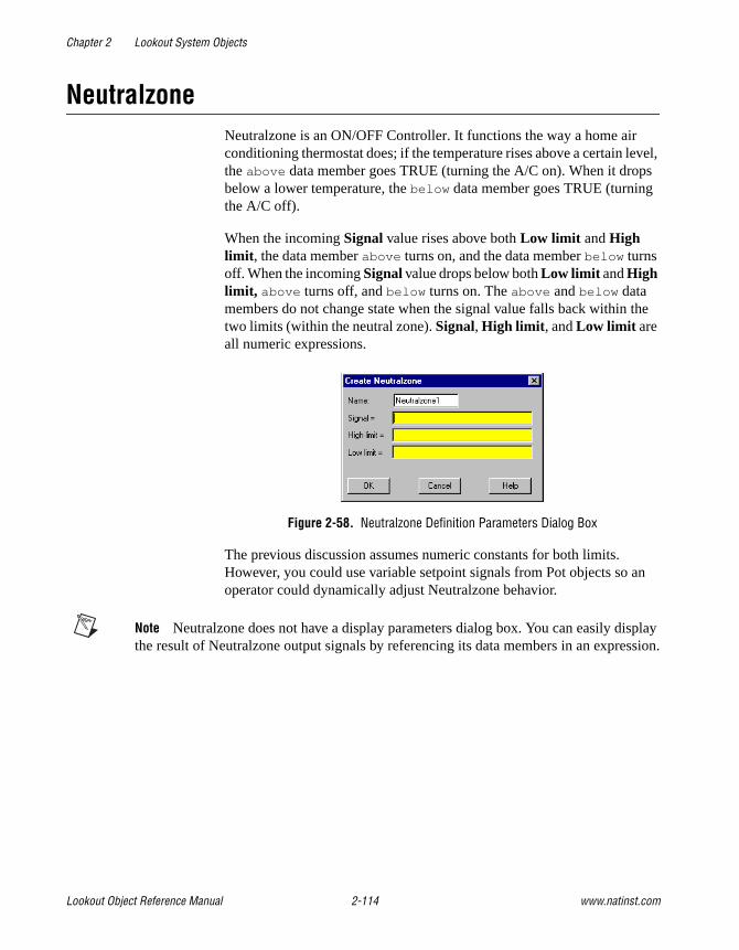
Chapter 2 Lookout System Objects
Lookout Object Reference Manual 2-114 www.natinst.com
NeutralzoneNeutralzone is an ON/OFF Controller. It functions the way a home air conditioning thermostat does; if the temperature rises above a certain level, the above data member goes TRUE (turning the A/C on). When it drops below a lower temperature, the below data member goes TRUE (turning the A/C off).
When the incoming Signal value rises above both Low limit and High limit , the data member above turns on, and the data member below turns off. When the incoming Signal value drops below both Low limit and High limit, above turns off, and below turns on. The above and below data members do not change state when the signal value falls back within the two limits (within the neutral zone). Signal, High limit , and Low limit are all numeric expressions.
Figure 2-58. Neutralzone Definition Parameters Dialog Box
The previous discussion assumes numeric constants for both limits. However, you could use variable setpoint signals from Pot objects so an operator could dynamically adjust Neutralzone behavior.
Note Neutralzone does not have a display parameters dialog box. You can easily display the result of Neutralzone output signals by referencing its data members in an expression.

Chapter 2 Lookout System Objects
© National Instruments Corporation 2-115 Lookout Object Reference Manual
Neutralzone Data Members
Comments You can use this object to turn pumps on and off or open and close valves based on line pressures or tank levels. Neutralzone objects prevent pumps from cycling on and off around a single setpoint, just as an air conditioning thermostat prevents your home air conditioner from incessantly starting and stopping.
Often the term deadband is mistakenly used to describe a neutral zone. However, deadbands refer to the amount of change a numeric value must travel in the reverse direction before the output numeric value begins to change.
Table 2-39. Neutralzone Data Members
Data Members Type Read Write Description
above logical yes no ON if signal is greater than both limits, OFF if signal is less than both limits, and does not change if signal is between both limits
below logical yes no ON if signal is less than both limits, OFF if signal is greater than both limits, and does not change if signal is between both limits
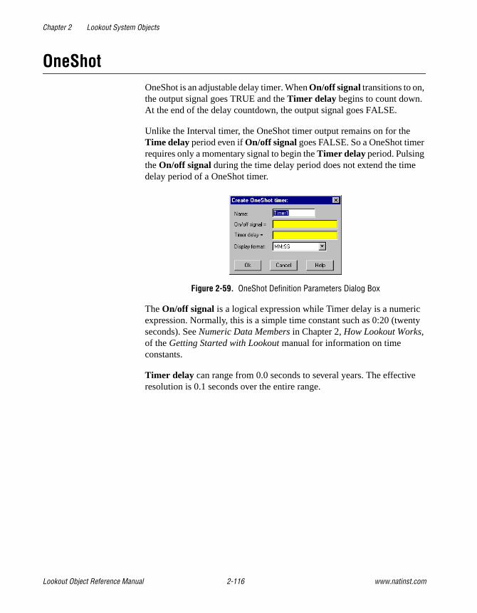
Chapter 2 Lookout System Objects
Lookout Object Reference Manual 2-116 www.natinst.com
OneShotOneShot is an adjustable delay timer. When On/off signal transitions to on, the output signal goes TRUE and the Timer delay begins to count down. At the end of the delay countdown, the output signal goes FALSE.
Unlike the Interval timer, the OneShot timer output remains on for the Time delay period even if On/off signal goes FALSE. So a OneShot timer requires only a momentary signal to begin the Timer delay period. Pulsing the On/off signal during the time delay period does not extend the time delay period of a OneShot timer.
Figure 2-59. OneShot Definition Parameters Dialog Box
The On/off signal is a logical expression while Timer delay is a numeric expression. Normally, this is a simple time constant such as 0:20 (twenty seconds). See Numeric Data Members in Chapter 2, How Lookout Works, of the Getting Started with Lookout manual for information on time constants.
Timer delay can range from 0.0 seconds to several years. The effective resolution is 0.1 seconds over the entire range.

Chapter 2 Lookout System Objects
© National Instruments Corporation 2-117 Lookout Object Reference Manual
The object is represented on a control panel by showing the time delay remaining in the format defined by the Display format parameter. It is updated approximately once per second. If the delay period has expired, it shows OFF.
Figure 2-60. OneShot Display Parameters Dialog Box
OneShot Data Members
Comments You can use the OneShot timer to hold a valve open for a set period of time after a pushbutton is pressed, or to prevent pump starts from occurring too rapidly in succession.
Related Objects DelayOff, DelayOn, Interval, Pot, TextEntry
Table 2-40. OneShot Data Members
Data Member Type Read Write Description
(implicit) logical yes no Logical timer value

Chapter 2 Lookout System Objects
Lookout Object Reference Manual 2-118 www.natinst.com
PagerPager is an object class Lookout uses to contact a numeric or alphanumeric pager through a modem, sending a message to the pager.
Figure 2-61. Numeric Only Pager Definition Parameters Dialog Box
Figure 2-62. Alphanumeric Pager Definition Parameters Dialog Box
Pager type determines whether the Pager object operates in numeric only or alphanumeric mode. A detailed description of the operation of these two modes follows.

Chapter 2 Lookout System Objects
© National Instruments Corporation 2-119 Lookout Object Reference Manual
Pager number is the phone number of the pager you want to contact. When the Pager object is in Alphanumeric mode, this number corresponds to the pager ID number.
Message is the message you want to send to the pager. Notice that in Numeric Only mode only numeric characters are sent.
Delay is how long the Pager object waits after dialing the pager number before it dials the message number. This parameter is valid in Numeric Only mode only.
Terminal number is the phone number of the remote paging terminal you want to contact. This parameter is valid in Alphanumeric mode only.
Retry attempts specifies the consecutive number of times Lookout attempts to establish communications with a device if it is not getting a valid response. After it tries the number of Retry attempts specified, the Pager object generates an alarm and releases the COM port. Refer to Chapter 3, Serial Communications, in the Lookout Developer’s Manual for more information. This parameter is valid in Alphanumeric mode only.
Receive timeout is the time delay Lookout uses in waiting for a response from a device before retrying the request. This parameter is valid in Alphanumeric mode only.
Baud rate indicates the baud rate Lookout uses to communicate with the modem and paging terminal.
Serial port specifies which COM port Lookout uses to communicate with your modem. You must have this COM port configured as dial-up under Options»Serial Ports.
Communication alarm priority determines the priority level of alarms generated by the Pager object. You can relate such alarms to communications with the modem or with the remote paging terminal.

Chapter 2 Lookout System Objects
Lookout Object Reference Manual 2-120 www.natinst.com
Pager Data Members
Pager Object Modes
Numeric OnlyIn Numeric Only mode, the Pager object establishes a connection with your local modem. Once this connection has been established and the pager number dialed, the Pager object waits for the time specified by Delay, then dials the number that is the message. Because the Message data member is a text value, the Pager object in Numeric Only mode omits any non-numeric characters from the message when it is sent.
Alphanumeric ModeIn Alphanumeric mode, the Pager object actually establishes a connection with a remote paging terminal, then transmits an alphanumeric message using Telocator Alphanumeric Protocol (TAP) version 1.8. TAP is an industry standard protocol for paging terminals that accept alphanumeric pages. Alphanumeric messages are limited to 250 characters. The text value in the Message data member will be truncated to this length if it is longer.
Pager Serial Port SettingsNotice that there are two different retry settings that affect the operation of the Pager object in Alphanumeric mode. The retry settings in the Pager object dialog box govern serial communications with the remote paging terminal. This means that after the two modems have connected and finished handshaking, and the serial transaction is underway, each individual frame is timed by the Receive timeout setting, and retried the number of times specified by Retry attempts.
Table 2-41. Pager Data Members
Data Member Type Read Write Description
Message text no yes Pager message
Phone text no yes Individual pager phone number or Page ID number
Send logical no yes Sends the message on transition from FALSE to TRUE
Chapter 2 Lookout System Objects
© National Instruments Corporation 2-121 Lookout Object Reference Manual
These retry settings will not dial the phone number again if the remote paging terminal for some reason does not answer or is busy, which happens occasionally. This setting and other important modem settings (including the AT initialization string that the Pager object must use on your modem) can be found in Option»Serial Ports, and should be chosen carefully. These settings are important in both Pager object modes.
Note You may have to increase your Receive Gap setting from its default of 5 to something closer to 20 or 25. You must also have your COM port configured as dial-up.
Pager QueueingThe Pager object queues up to 10 messages in either mode. If the object is in the process of sending out a page and the Send data member goes high again, the current value of the Message data member will be queued and sent out when the Pager object has time. Messages that are already in the queue will not be duplicated.
Pager Status MessagesPaging terminal refused logon
Alphanumeric only error code
Paging terminal forced disconnect
Alphanumeric only error code
Paging terminal NAKed block transmission
Alphanumeric only error code
Paging terminal abandoned block transmission
Alphanumeric only error code
No response within timeout period
This means that the modem is not responding to Lookout requests.
Queue full
The paging queue currently has 10 pages in it, and will not accept any more until at least one of those pages is successfully sent.
Garbled response
A response from the modem was corrupted or in an unrecognizable form.

Chapter 2 Lookout System Objects
Lookout Object Reference Manual 2-122 www.natinst.com
Panel Panel is a unique object class that accepts display members of other objects. Panels (Control panels) are a window into your process you can use to monitor and control your system by flipping switches, depressing pushbuttons, and turning knobs.
There is no limit as to the number of control panels you can create in Lookout or the number of objects or graphics that you can display on a given panel. Control panels can be any size, and you can display them within the Lookout workspace in various states (maximized, normal, minimized).
Create control panels with the Object»Create… command or with the Insert»Control panel… command. Both commands deliver the same result.
Figure 2-63. Panel Definition and Display Parameters Dialog Box
There are three distinct panel types: Normal, Popup, and Popup no icon.
A Normal control panel can be maximized, normal size, or minimized within the Lookout workspace. When you activate a Normal panel it appears at the size defined by its Height and Width . When you maximize a Normal panel, it fills the Lookout workspace. When you minimize a Normal panel it appears as an icon. The Normal option is typically selected for full-sized control panels.
Popup control panels can either be in a popup state or minimized (they cannot be maximized). When you activate a Popup panel it appears at the size defined by its Height and Width . When a Popup control panel is activated, it remains on top of all other panels until it is minimized. When you minimize a Popup panel it appears as a bar at the bottom of the Lookout screen.

Chapter 2 Lookout System Objects
© National Instruments Corporation 2-123 Lookout Object Reference Manual
Popup no icon control panels are identical to Popup panels except they are not represented by icons when minimized. When you minimize a Popup no icon panel it disappears from the Lookout workspace.
Note Because Popup no icon control panels are not represented by icons, they use less memory. (Microsoft Windows allocates a fixed amount of memory to each icon.) If you are experiencing memory problems when running a Lookout application that has many control panels, consider converting your Popup panels to Popup no icon.
Normal panels and Popup panels can be chosen by selecting their icon, using the Window menu command. Popup no icon control panels cannot; they can only be accessed by triggering their activate data member.
The Security levels settings are globally applied to a given control panel. The Control security level works in conjunction with all individual object security levels on that panel. The higher security level of the two is used to determine if an operator has control over the object. For example, consider a single Switch object with a security level of 4 that is displayed on two panels. The first panel has a control level of 6 and the second panel has a control level of 2. Only level 6 and higher operators are able to flip the switch on the first panel; however, level 4 and higher operators have control over the same switch on the second panel.
Viewing security can hide entire control panels from low level operators. This parameter affects the entire control panel. As an example take a control panel with a viewing security level of 6. If a level 5 (or lower) operator logs on, he is unable to see the control panel. In fact, he does not even know it exists because it is not listed in the Window menu and it is not shown as an icon. If a level 6 (or higher) operator logs on, the control panel instantly becomes available for display. This feature is useful for hiding panels that are rarely used or that contain sensitive information.

Chapter 2 Lookout System Objects
Lookout Object Reference Manual 2-124 www.natinst.com
This example shows a Normal control panel in a normal state and a Popup control panel in a minimized state. The Normal panel could easily be minimized or maximized by hitting the appropriate arrow button.
The following example is a typical scenario involving full screen control panels with multiple popup panels displayed at once.
This configuration maximizes the amount of information that you can display at once; and it allows you to have any number of different combinations of control panels displayed on your monitor.
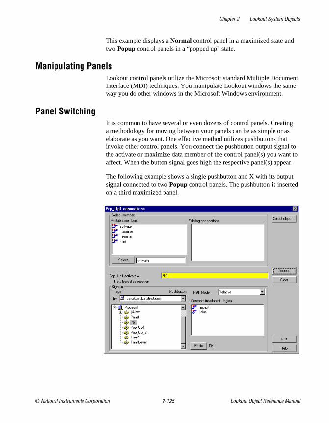
Chapter 2 Lookout System Objects
© National Instruments Corporation 2-125 Lookout Object Reference Manual
This example displays a Normal control panel in a maximized state and two Popup control panels in a “popped up” state.
Manipulating PanelsLookout control panels utilize the Microsoft standard Multiple Document Interface (MDI) techniques. You manipulate Lookout windows the same way you do other windows in the Microsoft Windows environment.
Panel SwitchingIt is common to have several or even dozens of control panels. Creating a methodology for moving between your panels can be as simple or as elaborate as you want. One effective method utilizes pushbuttons that invoke other control panels. You connect the pushbutton output signal to the activate or maximize data member of the control panel(s) you want to affect. When the button signal goes high the respective panel(s) appear.
The following example shows a single pushbutton and X with its output signal connected to two Popup control panels. The pushbutton is inserted on a third maximized panel.

Chapter 2 Lookout System Objects
Lookout Object Reference Manual 2-126 www.natinst.com
When you toggle out of Edit Mode and depress the button, both Popup control panels instantly appear, as shown in the following illustration. Of course you could have connected the pushbutton to another Normal panel instead, and it would have appeared as the new maximized panel.
As you can imagine, there is no limit to the number of connections between various signals and control panels. In fact, you can create complex expressions/alarms that automatically call up specific control panels.
Another way to move between panels is through the use of function keys. Like the $Keyboard object, each panel has its own set of data members representing the function keys F1 – F24. The following example shows the F2 data member of Panel1 connected to the activate data member of Panel2. The F2 data member of Panel2 is also connected to the activate data member of Panel3. This way an operator can depress F2 to page forward through several panels.
Panel1 Panel3Panel2
F1 F2 F1 F2 F1 F2
Panel3 Panel1
Chapter 2 Lookout System Objects
© National Instruments Corporation 2-127 Lookout Object Reference Manual
In similar fashion, the F1 data member of Panel3 is connected to the activate data member of Panel2 and the F1 data member of Panel2 is connected to the activate data member of Panel1. So now, Panel2.activate = Panel1.F2 OR Panel3.F1 . An operator can depress F2 to page forward through the control panels and F1 to page back through the control panels.
Special Considerations for “Home Panel”To ensure users do not get lost when switching between panels, you might define one panel as your master control panel, or home panel or computer main menu. You could connect the activate data member of your home panel to $Keyboard.Shift.F1, or perhaps to a pushbutton object. If connected to the function key, any time the user presses <SHIFT-F1> (no matter what panel he or she is looking at), the home panel is called, returning the operator to a familiar control panel.
You might also want the home panel to maximize upon startup. If you have already created a pushbutton to call the home panel, you can connect it to the maximize data member.
The exclamation point (! ) instructs Lookout to use the opposite of the pushbutton value. At startup, the pushbutton is not depressed so its value is FALSE. But because you are using the opposite of the pushbutton value, Panel1.maximize is TRUE at startup. Any time a user depresses CallHomePb after this connection is made, nothing happens until the pushbutton is released—at which time the panel is called.
Panel PrintYou can easily print a control panel using the Print Panel command. This function works equally well for both Normal and Popup panel types.
Print the contents of a panel by clicking on the panel control menu and then on Print Panel, or by connecting a logical expression to the Print data member of the desired control panel. A panel does not have to be visible to be printed.
Note Certain metafiles look different on the printed page than they do on the display screen. This means that parts of layered objects sometimes appear opaque on the screen, but translucent when drawn on paper.

Chapter 2 Lookout System Objects
Lookout Object Reference Manual 2-128 www.natinst.com
Note When you print a Normal panel, it is printed at its defined Height and Width parameters. If you define a panel whose Height and Width are at the default 400× 300 pixel setting, maximize the panel, and then add graphic elements to the full panel, those elements outside of the default 400 × 300 pixel range are not shown when the panel is printed. To print all the elements on a maximized panel, modify the Width and Height of the panel to match the full-screen dimension of the panel.
You can modify an existing control panel by toggling into edit mode and right-mouse clicking on its title bar. You can also modify a panel with the Object»Modify… menu command just like any other object.
Screen Resolution and Lookout GraphicsLookout graphics and control panels appear different, depending on the PC you are using and the resolution of your screen driver. When you position a graphic (or any other display element) onto a control panel, Lookout identifies the position you selected by recording the specific pixel position of the graphic. (A pixel is the smallest possible dot on the screen.) Lookout actually counts the number of pixels that the graphic is from the upper left-hand corner of the screen. When you subsequently recall a panel, Lookout knows the exact location to place the graphic.
The reason to bring this up is because different computer screen drivers have different screen resolutions. VGA screens are 640× 480 pixels. Super VGA screens typically range from 800 × 600 pixels to 1024 × 768 pixels. A panel created at 640 × 480 pixel resolution does not fill the screen of a 1024 × 768 super VGA monitor. A panel created at 1024 × 768 pixel resolution will overflow the screen of a 640× 480 VGA monitor.
It is best to create your panels using the display driver resolution of the computer on which you intend to run Lookout. If you are creating panels for use on multiple computers, consider developing panels using the display driver resolution of the most common resolution monitor (if you have a dozen Super VGA computers and one VGA computer, develop your panels in Super VGA, not VGA). You will then have to modify the panels slightly to fit on the less common resolution computer(s).
You can usually change the resolution of your screen from VGA to Super VGA by changing System Settings in Windows Setup. Refer to your Microsoft Windows manual for more information.
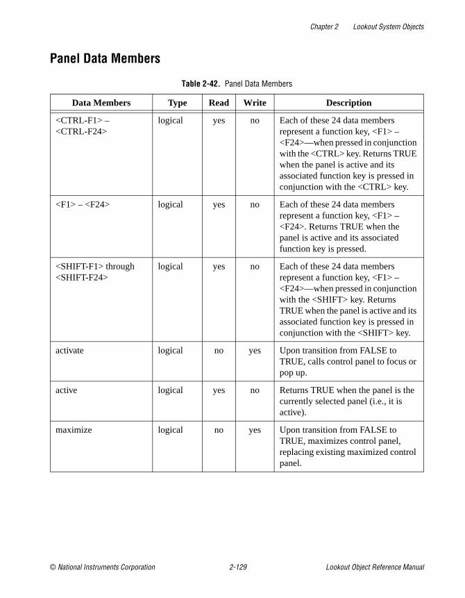
Chapter 2 Lookout System Objects
© National Instruments Corporation 2-129 Lookout Object Reference Manual
Panel Data Members
Table 2-42. Panel Data Members
Data Members Type Read Write Description
<CTRL-F1> – <CTRL-F24>
logical yes no Each of these 24 data members represent a function key, <F1> – <F24>—when pressed in conjunction with the <CTRL> key. Returns TRUE when the panel is active and its associated function key is pressed in conjunction with the <CTRL> key.
<F1> – <F24> logical yes no Each of these 24 data members represent a function key, <F1> – <F24>. Returns TRUE when the panel is active and its associated function key is pressed.
<SHIFT-F1> through <SHIFT-F24>
logical yes no Each of these 24 data members represent a function key, <F1> – <F24>—when pressed in conjunction with the <SHIFT> key. Returns TRUE when the panel is active and its associated function key is pressed in conjunction with the <SHIFT> key.
activate logical no yes Upon transition from FALSE to TRUE, calls control panel to focus or pop up.
active logical yes no Returns TRUE when the panel is the currently selected panel (i.e., it is active).
maximize logical no yes Upon transition from FALSE to TRUE, maximizes control panel, replacing existing maximized control panel.

Chapter 2 Lookout System Objects
Lookout Object Reference Manual 2-130 www.natinst.com
minimize logical no yes Upon transition from FALSE to TRUE, minimizes control panel to icon state.
print logical no yes Upon transition from FALSE to TRUE, sends the control panel to the Windows Print Manager.
Table 2-42. Panel Data Members (Continued)
Data Members Type Read Write Description

Chapter 2 Lookout System Objects
© National Instruments Corporation 2-131 Lookout Object Reference Manual
ParetoThe Pareto object class is one of the Lookout Statistical Process Control (SPC) tools and can play an important role in your Total Quality Management (TQM) program. This object class displays a frequency distribution of occurrences sorted by category so that you can identify the most frequently occurring anomalies or defects in your process.
The Pareto object class displays weighted and/or unweighted Pareto charts. The charts can be interactive, automatic, or a combination of both. An optional percentage line, showing cumulative percentage of factors, may be displayed. The number of factors to display, which may be less than the total number of factors defined, is user selectable. The chart background color, as well as the label, weight, and color of each factor, can be defined by the user.
The Pareto chart object definition dialog box is shown in the following illustration.
Figure 2-64. Pareto Definition Parameters Dialog Box
Reset is a logical expression that, on transition from FALSE to TRUE, resets all of the factor counts to zero.
Use Allow Interactive Choice to indicate whether the operator can increment (and possibly decrement) factor counts by clicking the mouse cursor on the Pareto chart object.
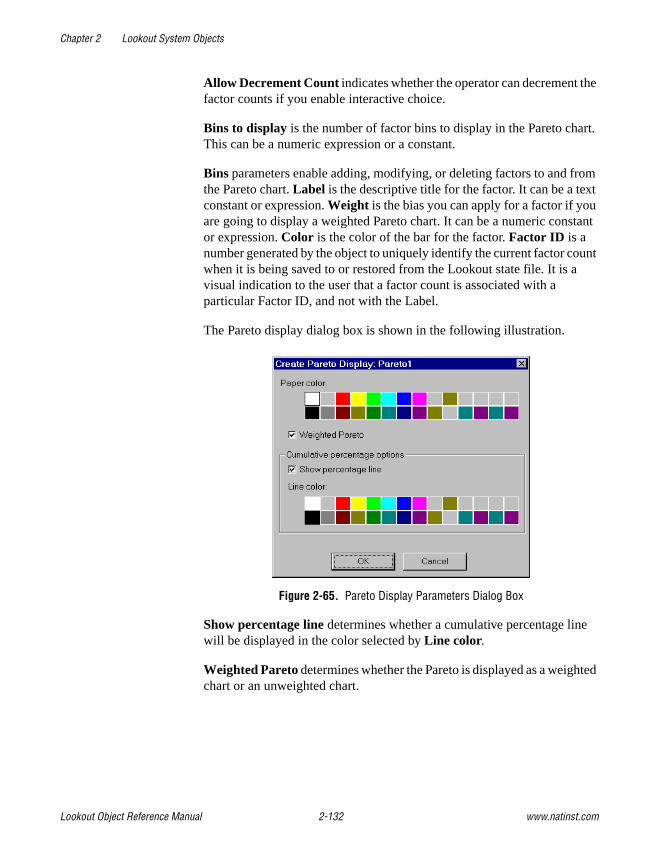
Chapter 2 Lookout System Objects
Lookout Object Reference Manual 2-132 www.natinst.com
Allow Decrement Count indicates whether the operator can decrement the factor counts if you enable interactive choice.
Bins to display is the number of factor bins to display in the Pareto chart. This can be a numeric expression or a constant.
Bins parameters enable adding, modifying, or deleting factors to and from the Pareto chart. Label is the descriptive title for the factor. It can be a text constant or expression. Weight is the bias you can apply for a factor if you are going to display a weighted Pareto chart. It can be a numeric constant or expression. Color is the color of the bar for the factor. Factor ID is a number generated by the object to uniquely identify the current factor count when it is being saved to or restored from the Lookout state file. It is a visual indication to the user that a factor count is associated with a particular Factor ID, and not with the Label.
The Pareto display dialog box is shown in the following illustration.
Figure 2-65. Pareto Display Parameters Dialog Box
Show percentage line determines whether a cumulative percentage line will be displayed in the color selected by Line color.
Weighted Pareto determines whether the Pareto is displayed as a weighted chart or an unweighted chart.

Chapter 2 Lookout System Objects
© National Instruments Corporation 2-133 Lookout Object Reference Manual
Weighted or Unweighted ChartsUsing the same Pareto object, you can display weighted or unweighted Pareto charts. An unweighted Pareto chart shows which factors occur most frequently. If the factors are of approximately equal importance, an unweighted chart is a good indication of trouble spots.
Figure 2-66. Unweighted Pareto Chart
If some factors are much more serious than others, using a weighted Pareto chart to ascertain the cost or exposure of a factor is a much more effective tool for identifying problem areas. For example, in the unweighted Pareto chart in Figure 2-66, factor 1 and factor 5 together account for 50 percent of the defect occurrences. However, as you can see on the weighted Pareto chart in Figure 2-67, factor 4 alone accounts for 60.8 percent of the total expense of all defects.

Chapter 2 Lookout System Objects
Lookout Object Reference Manual 2-134 www.natinst.com
Figure 2-67. Weighted Pareto Chart
Incrementing Factor CountsYou can use a Pareto chart to interactively or automatically increment factor counts. In fact, the object can accept any combination of automatic and interactive inputs.
If you select the Allow Interactive Choice option in the object definition dialog box, the operator can manually increment factor counts. To do this, the operator clicks the mouse cursor on the Pareto chart object. This pops up box that lists all the possible factors you can choose. The factor that the cursor is on when the operator clicks on the chart determines which factor is highlighted when the dialog box pops up. In this example, the mouse cursor was over the factor 2 bin.
If you select the Allow Decrement Count option in the object definition dialog box, the Decrement button is displayed in the pop-up, allowing the operator to decrement a factor count. Operators with a high enough security level can correct errors if necessary.

Chapter 2 Lookout System Objects
© National Instruments Corporation 2-135 Lookout Object Reference Manual
Pareto Data MembersThe Pareto object can use external connections to trigger the factor counts automatically. You can connect a pushbutton, an alarm, an expression, a PLC output, and so on, to a factor trigger to increment a factor count on a transition from FALSE to TRUE. The following table lists data members of the Pareto object class.
Table 2-43. Pareto Data Members
Data Members Type Read Write Description
count.sorted1 – 1000 numeric yes no The count in the respective sorted-by-count factor bin.
count.weighted.sorted1 – 1000
numeric yes no The weighted count in the respective sorted-by-weighted-count factor bin.
count.weighted1 – 1000 numeric yes no The weighted count in the respective unsorted factor bin.
count1 – 1000 numeric yes no The count in the respective unsorted factor bin.
factor1 – 1000 logical no yes On transition from FALSE to TRUE, increment the respective factor count by 1.
label.sorted1 – 1000 text yes no The label of the respective sorted-by-count factor bin.
label.weighted.sorted1 – 1000
text yes no The label of the respective sorted-by-weighted-count factor bin.
label1 – 1000 text yes no The label of the respective unsorted factor bin.
percent.sorted1 – 1000 numeric yes no The percent of the total count in the respective sorted-by-count factor bin.
percent.weighted.sorted1 – 1000
numeric yes no The percent of the total weighted count in the respective sorted-by-weighted-count factor bin.
percent.weighted1 – 1000
numeric yes no The percent of the total weighted count in the respective unsorted factor bin.

Chapter 2 Lookout System Objects
Lookout Object Reference Manual 2-136 www.natinst.com
percent1 – 1000 numeric yes no The percent of the total count in the respective unsorted factor bin.
total numeric yes no The total of all unweighted factor counts in all defined factors.
total.shown numeric yes no The total of all unweighted factor counts in all currently displayed factors.
total.shown.weighted numeric yes no The total of all weighted factor counts in all currently displayed factors.
total.weighted numeric yes no The total of all weighted factor counts in all defined factors.
visible logical yes yes When TRUE, the Pareto chart becomes visible on the control panel. When FALSE, it is invisible. The default value is TRUE.
Table 2-43. Pareto Data Members (Continued)
Data Members Type Read Write Description

Chapter 2 Lookout System Objects
© National Instruments Corporation 2-137 Lookout Object Reference Manual
PIDThe PID object compares a Process Variable to a Setpoint. If there is a difference, it calculates the error and adjusts its output to compensate until the Process Variable is equal to the Setpoint.
PID stands for Proportional-Integral-Derivative. These are three factors in the equation that can be applied against the calculated error. You specify Gain which is the proportional factor, Reset (the integral factor), and Rate (the derivative factor) to define how the object responds to the error.
Note The way in which the PID object responds to your process can vary greatly according to the parameters you enter and the process you are controlling. Any discussion regarding tuning of a PID loop falls outside of the topics addressed in this manual.
Figure 2-68. PID Definition Parameters Dialog Box
Type selects either positional control or velocity control. Detailed descriptions of both control modes are provided in the following sections.
Process Variable (PV) is typically the numeric signal from the field that you want to control. The PID loop equation does not expect this value to be normalized; rather the PID object performs the scaling of loop input and output values from engineering units.
Setpoint (SP) is typically the value of a Pot object, a constant numeric value, or the output signal from another PID object in a cascaded loop. Like the process variable, the setpoint is also scaled internally by the PID object.

Chapter 2 Lookout System Objects
Lookout Object Reference Manual 2-138 www.natinst.com
Setpoint Min and Max are numeric constants that specify the range of SP and PV in engineering units.
Manual Output is a numeric parameter that specifies the output of the object when it is in manual mode; that is, when the Automatic Enable expression is FALSE. Users typically enter either a constant, or the name of a Pot object in this field.
Output Min and Max are numeric constants that specify the range of the object output signal. The output is often referred to as the manipulated variable (MV).
Sample Pulse indicates the frequency at which the PID object executes. This parameter field can contain either a numeric constant or a logical variable. If you use a numeric constant (like 0:01 for one second), the object calculates a new output value at the defined frequency. If you use a logical variable, then the variable should pulse at some desired frequency. Any time the pulse transitions from FALSE to TRUE, the object calculates a new output value. It is very important not to over-sample your data. Start with a slow sample rate.
Gain (Kc) is a numeric parameter that determines the overall sensitivity of the PID loop to changes in error. A gain value of 1.00 changes the proportional increment of the PID equation by 50 percent when there is a 50 percent change in error. A gain value of 0.25 changes the proportional increment by 12.5 percent with a 50 percent change in error.
Reset (Ti) also referred to as integral time, is a numeric parameter that specifies the amount of time it takes for the integral sum increment of the PID loop equation to react to a given change in error. For example, if the error suddenly changes by 20% and reset = 0:10 (10 seconds), the integral increment of the PID loop increases at a rate of 0.5 percent per second until it has changed by 20 percent after 40 seconds. This 20 percent contribution is multiplied by the gain, so if the gain is 2.0, the integral term contributes 40% to the loop output in this example. In other words, the shorter the reset time, the faster the object output responds to a change in either PV or SP.
Rate (Td) also referred to as derivative time, is a numeric parameter that dampens loop response. It is calculated based upon the rate of change of PV and adds an increment to the output that attempts to anticipate and slow the change in PV. As an example, if PV is increasing by 10 percent per minute, and rate is 0:30 (0.5 minutes), the derivative increment is calculated as –(10%/min. × 0.5 minutes)= –5% (or –0.05). So the derivative term would contribute –5% to the output if the gain is 1.0.

Chapter 2 Lookout System Objects
© National Instruments Corporation 2-139 Lookout Object Reference Manual
Automatic Enable specifies whether the loop controller is operating in automatic mode or manual mode. When it is ON, controller is operating in automatic mode and the output signal is being calculated using the PID algorithm. In manual mode, the output signal is equal to the Manual Output input signal.
The PID object provides bumpless transfer from manual to automatic operation—when the controller is switched from manual to automatic, its output begins changing from the current manual output setting. Contrast this with a loop controller without bumpless transfer. When such a controller is in manual, the integral term continues to accumulate. When the controller is switched to automatic, the loop controller would immediately go to a high or low output.
Add proportional increment specifies whether the loop equation adds the proportional increment of the PID equation to MV. This value is typically ON.
Freeze Enable specifies whether the loop bias should be frozen or actively back-calculated when the controller output signal goes out of range. In either case, the loop controller is protected from integral wind-up, but if Freeze Enable is OFF (recommended setting), the bias is actively back-calculated to prevent controller overshoot when PV comes back into range.
The PID object protects against integral windup in one of two selectable ways: It either freezes the bias term when the controller output goes out of range, or it actively back-calculates the bias so the controller responds smoothly with less chance of overshoot when its output returns to range.
Output Time is a numeric constant that specifies the time domain of the controller output when operating in velocity mode. For example, if the object output controls a value with dimensions of inches per minute, output time would be 1:00 (one minute).
Low Limit Enable is used in velocity control mode. It is an optional logical signal that clips the PID output to a value grater than or equal to zero when TRUE. This input can be used to signal the controller that the low limit switch on the controlled device has been activated.
High Limit Enable is used in velocity control mode. It is an optional logical signal that clips the PID output to a value less than or equal to zero when TRUE. This input can be used to signal the controller that the high limit switch on the controlled device has been activated.

Chapter 2 Lookout System Objects
Lookout Object Reference Manual 2-140 www.natinst.com
PID Positional ControlWhen you select Position , the PID object calculates the output as follows:
where:
dT = time increment between current and previous calc.
MV = controller output (manipulated variable)
Kc = controller gain (units: % output / % error)
en = error at sample n (error = SP – Pvn)
integral sumn = integral sumn–1 + dT / Ti (en – en–1) also called bias
Td = rate, or derivative time
Pvn – Pvn–1 = change in PV from previous to current calculation
PID Velocity ControlThe output of the velocity form of the PID equation is the velocity or rate of change of the output signal. The velocity form of the PID equation is the first derivative of the position form of the PID equation with respect to time, so the result is the rate of change of the controller position.
When you select Velocity , the object calculates the output as follows:
where:
MV = controller output position (manipulated variable)
dMV = contoller output velocity
Kc = controller gain (units: % output / % error)
en = error at sample n (error = SP – Pvn)
Td = rate, or derivative time
PV = process variable
MV K c en integral sumn Td dT Pvn Pvn 1––( )⁄–+( )=
dMV MV n MV n 1– Kc en en 1––( ) Tsen Ti Td Ts⁄+⁄ Pvn 2PVn 1– PVn 2–+–( )+( )=–=

Chapter 2 Lookout System Objects
© National Instruments Corporation 2-141 Lookout Object Reference Manual
PID Data Members
Comments The proportional term of the PID equation contributes an amount to the output equal to the error multiplied by the Gain. This provides an immediate output compensation when the error value changes.
The integral term of the PID equation calculates a running total of the error summed (or integrated) over time—think of this increment as adding the area under the curve of a plot of error versus time. While SP is greater than PV, the integral term is increasing, and while PV is greater than SP, the integral term is decreasing. The sensitivity of the integral output is set by the gain and the reset variables. Integral action can be eliminated by setting Reset to a higher number. At least some Integral action is required, however, for the loop controller to operate properly with bias adjustment. If you do not use any Integral, you may experience offset, a condition in which the output is adjusted to compensate for the error, but not enough to correct the error.
The derivative term of the PID equation acts to dampen the change in PV by adding a negative value for a positive-going PV and a positive value for a negative-going PV. Because PV is subject to sudden small changes and signal noise in many process loops, derivative action can cause a loop to respond erratically. Rate can be set to 0, especially when initially tuning the loop, to eliminate derivative action. Derivative action dampens process loops that tend to oscillate around the setpoint and thus provide better loop response. Rapidly changing loops such as liquid flow control in a pipe may not benefit from derivative action, but more sluggish loops that tend to build momentum, such as temperature control, benefit from derivative action by preventing overshoot and dampening oscillatory action.
Table 2-44. PID Data Members
Data Members Type Read Write Description
Error numeric yes no This is the difference between the Setpoint (SP) and the Process Variable (PV).
Output numeric yes no This is the PID controller output value, also called MV, or the manipulated variable. This value is either the result of the PID loop equation or the Manual Output , depending on the state of Automatic Enable.

Chapter 2 Lookout System Objects
Lookout Object Reference Manual 2-142 www.natinst.com
PipePipe displays different color rectangles (pipes) on a control panel as defined by the values of Conditional expressions. Pipe determines which color rectangle to display based on the order and current status of your Conditional expressions. If several Conditional expressions are TRUE at once, Pipe displays the color associated with the first TRUE expression. Conditional expressions must result in logical values.
Figure 2-69. Pipe Definition Parameters Dialog Box
Pipe Data Members
Comments You can easily create a complex piping network scheme (including changing colors) with a single Pipe object. Display the object on a control panel and copy the pipe display with the shift-drag method to create additional pipes with the same parameters. You can then move, resize, and group the pipes as you choose.
Table 2-45. Pipe Data Members
Data Members Type Read Write Description
none — — — Pipe does not have data members.

Chapter 2 Lookout System Objects
© National Instruments Corporation 2-143 Lookout Object Reference Manual
PlaywavePlaywave connects Microsoft standard wave form files (.wav ) to events in Lookout. Playwave plays the audio file specified by Wave file when Play when transitions from off to on. Play when is a logical expression and might range from a simple pushbutton, to a digital input from a PLC, to an alarm generated in Lookout. You can also create your own custom audio files with various software products. Therefore, you can connect individual alarms to custom wave files to be played each time an alarm goes TRUE.
Figure 2-70. Playwave Definitions Parameters Dialog Box
Playwave Data Members
Comments Many computers do not come equipped with quality speakers built in. If this is the case, your wave files may sound distorted or may even be inaudible. If you want to take advantage of the Playwave feature, you may need to buy additional hardware, in particular a Microsoft Windows compatible sound board (with Windows driver) and external speakers.
Table 2-46. Playwave Data Members
Data Members Type Read Write Description
none — — — Playwave does not have any data members

Chapter 2 Lookout System Objects
Lookout Object Reference Manual 2-144 www.natinst.com
PotPot is a potentiometer that you use to change numeric setpoint values. You can display Pots on a control panel as a knob, vertical slider, horizontal slider, increment/decrement pushbuttons, or digital entry. You can also use Pots as multiple-position switches.
If you change the background color of a panel and add a Pot object displayed as a slider, its color is always gray. To change the background color of a Pot to match your panel, select the Pot object, then pick Change»Background Color from the menu.
Figure 2-71. Pot Definitions Parameters Dialog Box
Minimum is the lowest value signal the pot will generate.
Maximum is the highest value signal the pot will generate.
Resolution is the smallest increment of change, or detent spacing the Pot supports.
Position source determines where the value of the Pot resides. Local indicates the value of the Pot lies within the object itself—on the control panel.
Remote Pots get their values from a remote source, often the register on a controller they are connected to. Adjusting the Pot changes the value in

Chapter 2 Lookout System Objects
© National Instruments Corporation 2-145 Lookout Object Reference Manual
the register, and changing the value in the register adjusts the Pot. In effect, the Pot is tracking a remote value. This is especially useful when you want to prevent Lookout from changing the value of setpoints or registers upon initial startup, or reconnection of lost communication.
The Remote option calls for a URL to locate the data member you want to connect to. The URL field is green, and you cannot use a complex expression as a URL. If you need to use one RadioButton for several purposes, you can use a Symbolic Link to make a more complex connection than that possible with a URL.
You can right-click in the URL field and use the URL Editor dialog box to assemble the URL, in the same way you use the Lookout expression editor.
A remote position source connection is completely reciprocal. A change in your Lookout control changes the data member that control is remoted to. Any change in that data member also changes the control. It is not necessary, and is incorrect, to use the Edit Connections dialog box to connect a control object to its controlled data member.
Because the remote connection is reciprocal, you can only make such a connection to a data member that is either writable, or readable and writable.
When a process with remoted controls first opens, those controls take their initial values by following the URL to read the data members they are remoted to. The control will be covered by a red X to indicate that the remote connection is not functioning.
Note You should use Remote to connect a control in a client process to a data member in a server process. Connections inside a single process can be made using Object»Edit Connections.
Because complex expressions are read-only values, you cannot remote directly to them. For the same reason, you cannot remote one control to another control’s (intrinsic) data member (though you can remote a control to another control’s value data member).
Much like Remote Pots, DDE (Dynamic Data Exchange) Pots get their values from a remote source. This could be a cell in a spreadsheet, another DDE aware application, or a second copy of Lookout running on the network. The last DDE parameters used on any object automatically become the default values for any new DDE object.

Chapter 2 Lookout System Objects
Lookout Object Reference Manual 2-146 www.natinst.com
Control security level specifies the minimum security level operators must have to gain access to this individual object, and thus control it.
The Log events option creates a permanent audit trail for the object—who did what and when. All adjustments of the Pot are logged to disk, including the time of the adjustment, the operator account name, and what adjustment was made.
Figure 2-72. Pot Display Parameters Dialog Box
Note You can modify the background color on vertical and horizontal sliders with the Change»Background color… menu command. You can modify the font and font color of digital Pots using Change commands.
Pot Data Members
Table 2-47. Pot Data Members
Data Member Type Read Write Description
(implicit) numeric yes no Current value
decrement logical no yes When this data member value transitions from FALSE to TRUE, the implicit value of the Pot object decreases by the Pot Resolution amount.
enable logical no yes If TRUE (the default), enables DDE. If FALSE, disables DDE. The default value is on. This input is ignored for non-DDE TextEntry objects.

Chapter 2 Lookout System Objects
© National Instruments Corporation 2-147 Lookout Object Reference Manual
enterValue logical no yes Under specific circumstances, when this value transitions from FALSE to TRUE, pops up a Enter new value dialog box for an operator to use in entering a value for the Pot. See the note following the table for more detailed information.
The enterValue data member is designed for use under unusual circumstances, in particular when pointing devices are not available on a computer running Lookout. Because of its unusual operation, this data member should not be used unless it is necessary for hardware reasons.
increment logical no yes When this data member value transitions from FALSE to TRUE, the implicit value of the pot object increases by the Resolution amount.
reset logical no yes While this value equals TRUE, the control will be set to the value in resetvalue .
resetvalue numeric no yes Sets the value a control will take when the reset data member transitions from FALSE to TRUE.
value numeric yes yes The current value of the control. If you have remoted this control, then value is the current value of the position source.
visible logical no yes When FALSE, the Pot object cannot be seen on the display panel. When TRUE, the Pot can be seen and controlled.
Table 2-47. Pot Data Members (Continued)
Data Member Type Read Write Description

Chapter 2 Lookout System Objects
Lookout Object Reference Manual 2-148 www.natinst.com
Note When the enterValue input transitions from FALSE to TRUE, and if the Pot is visible, if Lookout is not in edit mode, and if the Pot has at least one digital display, the Enter new value dialog box pops up so an operator can input a value, just as if the operator had clicked on the digital display.
The numeric format and position used for the dialog box are based on the digital display for a Pot. Even if the panel containing the Pot digital display is inactive, the Enter new value dialog box will pop up. You can prevent this by predicating the enterValue input on the panel's active data member.
Comments Potentiometers are one of the most common control objects used in process controls. Using Pots, a plant operator can make setpoint changes with the mouse. Pots also work well as H-O-A switches. To create an HOA switch with a Pot, specify the minimum as 1, the maximum as 3, and the resolution as 1.
The increment and decrement data members enable quick connection of Pot objects to $Keyboard and Panel function keys, and screen Pushbuttons. These are often used to control Pot objects when Lookout is running on an industrial PC platform that has restricted or no mouse functionality.

Chapter 2 Lookout System Objects
© National Instruments Corporation 2-149 Lookout Object Reference Manual
PulsePulse is a timer that generates a periodic pulse of a specified duration. When On/off signal transitions to ON, the output signal turns on for the pulse duration time and then turns off for the remainder of the period. The output signal immediately turns off when the On/Off signal goes low.
Timer period is the time interval for the full pulse cycle, and Timer duration is the width of each pulse. These parameters can range from 0.0 seconds to several years, with an effective resolution of 0.1 seconds over the entire range. Timer duration should always be less than Timer period.
The object is represented on a control panel by showing the time remaining before the output changes state. It is depicted in the format defined by the Display format parameter. It is updated approximately once per second. If the On/Off signal is FALSE, it shows OFF.
Figure 2-73. Pulse Definition Parameters Dialog Box
The On/off signal is a logical expression while Timer period and Timer duration are numeric expressions. Normally, these are simple time constants such as 0:20 (twenty seconds). See Numeric Data Members in Chapter 2, How Lookout Works, of the Getting Started with Lookout manual for information on entering time constants.

Chapter 2 Lookout System Objects
Lookout Object Reference Manual 2-150 www.natinst.com
Figure 2-74. Pulse Display Parameters Dialog Box
Pulse Data Members
Comments Pulse can be used to periodically open a valve for a specified time duration. It can also act as a flasher to turn text and graphic signals on and off for display purposes.
Related Objects DelayOff, DelayOn, Interval, OneShot, TextEntry
Table 2-48. Pulse Data Members
Data Members Type Read Write Description
(implicit) logical yes no Logical timer value
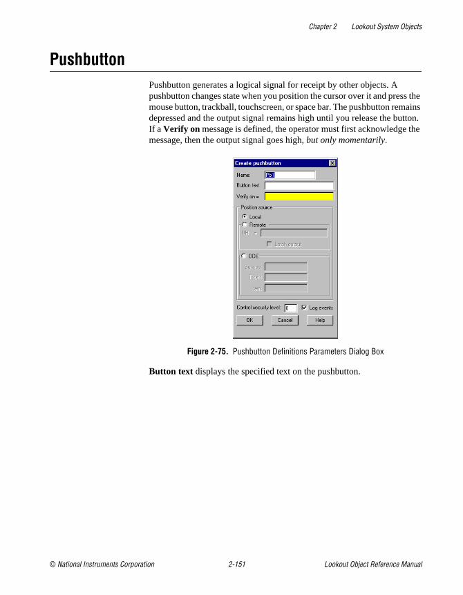
Chapter 2 Lookout System Objects
© National Instruments Corporation 2-151 Lookout Object Reference Manual
PushbuttonPushbutton generates a logical signal for receipt by other objects. A pushbutton changes state when you position the cursor over it and press the mouse button, trackball, touchscreen, or space bar. The pushbutton remains depressed and the output signal remains high until you release the button. If a Verify on message is defined, the operator must first acknowledge the message, then the output signal goes high, but only momentarily.
Figure 2-75. Pushbutton Definitions Parameters Dialog Box
Button text displays the specified text on the pushbutton.

Chapter 2 Lookout System Objects
Lookout Object Reference Manual 2-152 www.natinst.com
Use Verify on to create a dynamic text expression to be displayed in a message dialog box. See Chapter 6, Security, in the Lookout Developer’s Manual for more information on security.
Figure 2-76. Verification Message Dialog Box
Position source determines where the value of the Pushbutton resides. Local indicates the value of the Pushbutton lies within the Pushbutton itself—on the control panel. If the pushbutton is not depressed its signal is OFF, if depressed its signal is ON.
Remote Pushbuttons get their values from a remote source, often the register in a controller they are connected to. Depressing the pushbutton changes the status of the register, and changing the status of the register depresses the pushbutton.
The Remote option calls for a URL to locate the data member you want to connect to. The URL field is green, and you cannot use a complex expression as a URL. If you need to use one RadioButton for several purposes, you can use a Symbolic Link to make a more complex connection than that possible with a URL.
You can right-click in the URL field and use the URL Editor dialog box to assemble the URL, in the same way you use the Lookout expression editor.
A remote position source connection is completely reciprocal. A change in your Lookout control changes the data member that control is remoted to. Any change in that data member also changes the control. It is not necessary, and is incorrect, to use the Edit Connections dialog box to connect a control object to its controlled data member.
Because the remote connection is reciprocal, you can only make such a connection to a data member that is either writable, or readable and writable.

Chapter 2 Lookout System Objects
© National Instruments Corporation 2-153 Lookout Object Reference Manual
When a process with remoted controls first opens, those controls take their initial values by following the URL to read the data members they are remoted to. The control will be covered by a red X to indicate that the remote connection is not functioning.
Note You should use Remote to connect a control in a client process to a data member in a server process. Connections inside a single process can be made using Object»Edit Connections.
Because complex expressions are read-only values, you cannot remote directly to them. For the same reason, you cannot remote one control to another control’s (intrinsic) data member (though you can remote a control to another control’s value data member).
When you select the Remote option, you can choose whether or not the Pushbutton latches its output. The Latch output check box configures Lookout for controlling a latching-relay.
When a user clicks on a Pushbutton that has latching selected, the pushbutton remains depressed, sending an ON signal (TRUE or high) until the Remote Position signal turns ON. Assume for example that an operator clicks on MotorStartPb , configured above. The pushbutton remains pushed in, sending a TRUE signal, until PLC.C101 goes TRUE. As soon as PLC.C101 goes TRUE, the pushbutton releases.
Much like Remote Pushbuttons, DDE (Dynamic Data Exchange) Pushbuttons get their values from a remote source. This could be a cell in a spreadsheet, another DDE aware application, or a second copy of Lookout running on the network. See Chapter 5, Dynamic Data Exchange, in the Lookout Developer’s Manual for information on Service, Topic, and Item parameters.
Control security level specifies the minimum security level operators must have to gain access to this individual object, and thus control it. See Chapter 6, Security, in the Lookout Developer’s Manual for more information on security.

Chapter 2 Lookout System Objects
Lookout Object Reference Manual 2-154 www.natinst.com
The Log events option creates a permanent audit trail for the object—who did what and when. Any depression of the Pushbutton is recorded to disk, including the time the button was depressed, and the operator’s account name. See Chapter 7, Logging Data and Events, in the Lookout Developer’s Manual for more information on logging events.
Figure 2-77. Pushbutton Display Parameters Dialog Box
Pushbutton Data Members
Table 2-49. Pushbutton Data Members
Data Members Type Read Write Description
(implicit) logical yes no Value of object (TRUE when button is depressed)
enable logical no yes If TRUE (the default), enables DDE. If FALSE, disables DDE. The default value is on. This input is ignored for non-DDE TextEntry objects.
reset logical no yes While this value equals TRUE, the control will be set to the value in resetvalue .
resetvalue numeric no yes Sets the value a control will take when the reset data member transitions from FALSE to TRUE.

Chapter 2 Lookout System Objects
© National Instruments Corporation 2-155 Lookout Object Reference Manual
value numeric yes yes The current value of the control. If you have remoted this control, then value is the current value of the position source.
visible logical no yes When FALSE, the Pushbutton cannot be seen on the display panel. When TRUE, the button can be seen and controlled.
Table 2-49. Pushbutton Data Members (Continued)
Data Members Type Read Write Description

Chapter 2 Lookout System Objects
Lookout Object Reference Manual 2-156 www.natinst.com
RadioButtonThe RadioButton object creates a set of radio buttons on your panel. You can have from 2 to 40 buttons in a set. Only one button at a time can be activated in each radio button group.
Figure 2-78. RadioButton Definition Parameters Dialog Box
Set the Buttons (2-40) in each set. You can have as many as 40 buttons in each group, but you must have at least 2.
Position source determines where the value of the RadioButton resides. Local indicates the value of the RadioButton lies within the object itself—on the control panel.
The Remote option tells Lookout to initialize the RadioButton value from a remote source. Adjusting the RadioButton changes the value in the register, and changing the value in the register adjusts the RadioButton. In effect, the RadioButton is tracking a remote value. This is especially useful when you want to prevent Lookout from changing the value of setpoints or registers upon initial startup, or reconnection of lost communication.
The Remote option calls for a URL to locate the data member you want to connect to. The URL field is green, and you cannot use a complex expression as a URL. If you need to use one RadioButton for several purposes, you can use a Symbolic Link to make a more complex connection than that possible with a URL.

Chapter 2 Lookout System Objects
© National Instruments Corporation 2-157 Lookout Object Reference Manual
You can right-click in the URL field and use the URL Editor dialog box to assemble the URL, in the same way you use the Lookout expression editor.
A remote position source connection is completely reciprocal. A change in your Lookout control changes the data member that control is remoted to. Any change in that data member also changes the control. It is not necessary, and is incorrect, to use the Edit Connections dialog box to connect a control object to its controlled data member.
Because the remote connection is reciprocal, you can only make such a connection to a data member that is either writable, or readable and writable.
When a process with remoted controls first opens, those controls take their initial values by following the URL to read the data members they are remoted to. The control will be covered by a red X to indicate that the remote connection is not functioning.
Note You should use Remote to connect a control in a client process to a data member in a server process. Connections inside a single process can be made using Object»Edit Connections.
Because complex expressions are read-only values, you cannot remote directly to them. For the same reason, you cannot remote one control to another control’s (intrinsic) data member (though you can remote a control to another control’s value data member).
Note You cannot break a group of radio buttons into multiple rows.
Enter any text for the buttons in the Button labels field. Separate each button label with a comma. If you need to include a comma or a backslash in any button text, precede that character with a backslash(\ ). If you want to leave a button blank, you can enter two commas without any text or numbers between the commas. You do not have to enter a label for every button. Lookout will leave each button after your last label entry blank. If you enter more labels than you have set buttons, your labels will be preserved but not displayed.
To log changes in button state, check the Log Events checkbox.

Chapter 2 Lookout System Objects
Lookout Object Reference Manual 2-158 www.natinst.com
Security level sets the minimum security level an operator must have to change the radio buttons.
Figure 2-79. RadioButton Display Parameters Dialog Box
Figure 2-80. RadioButton Display Parameters Dialog Box with Custom Graphics Chosen

Chapter 2 Lookout System Objects
© National Instruments Corporation 2-159 Lookout Object Reference Manual
You can use a standard Lookout pushbutton, standardized radio buttons, or custom graphics for your radio button groups.
Notice that you cannot enter text in the Create Display dialog box. You must enter any text you intend to use in the RadioButton Definition Parameters dialog box. You can change font and text size in the Create Display dialog box. The first text label you entered for your radio button is displayed in the Preview field so you see the effect of font changes.
The default display uses a standard Radio Button display. You can adjust text and background color for any of your display choices.
Selecting Standard Pushbutton displays standard on/off buttons in your radio button array.
Select Customized Button for a free range of choices from the Lookout graphics library, or create your own ON/OFF indicators for a radio button array. See the Creating Custom Graphics section of Chapter 2, Graphics, in the Lookout Developer’s Manual for detailed information on creating your own graphics for use on a Lookout control panel.
Set the Orientation of the radio button array to horizontal or vertical by checking the appropriate checkbox. Set label text Justification and button Frame style in the appropriate fields.
Related Objects L3Pot, L3Pushbutton, L3Switch, Pot, Pushbutton, Switch
RadioButton Data Members
Table 2-50. RadioButton Data Members
Data Member Type Read Write Description
1-40 logical yes no Reports ON/OFF status of each button in a radio button set.
current numeric yes no Reports which radio button is active in a set.
(implicit) numeric yes yes Radiobutton value.
value numeric yes yes Number of the currectly active radiobutton.
visible logical yes yes Controls visibility of a radio button set. Default=TRUE.

Chapter 2 Lookout System Objects
Lookout Object Reference Manual 2-160 www.natinst.com
RecipeRecipe objects are an efficient means of importing large arrays of data (namely recipes and their ingredients) into Lookout using an Excel (.xls ) spreadsheet. Once created and implemented, the operator can easily and quickly change the current recipe with the click of the mouse, thus selecting a new set of ingredients.
The best way to describe how the Recipe class works is to step through a typical example, in this case involving cookie manufacture.
There are two steps to creating and implementing a recipe object. First, you define your recipes with their respective ingredients in a spreadsheet program such as Excel (anything that creates an .xls file will work—including Lotus 123). You can define up to 1,000 recipes in a single .xls file. Each recipe can have up to 255 ingredients. Three cookie recipes are defined in this spreadsheet.
The first row of the spreadsheet is reserved for ingredient names. They begin in column B. These ingredient names later become alias data members of the Recipe object. Therefore, ingredient names must be unique. They cannot have the same name as a native data member (see the Recipe Data Member table for data member names). Also, you cannot name an ingredient missing ; this is a reserved word. Valid characters in
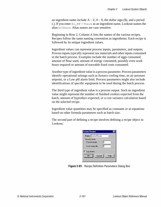
Chapter 2 Lookout System Objects
© National Instruments Corporation 2-161 Lookout Object Reference Manual
an ingredient name include A – Z, 0 – 9, the dollar sign ($), and a period (.). If you enter Hi_@#!!There as an ingredient name, Lookout names the alias HiThere . Alias names are case sensitive.
Beginning in Row 2, Column A lists the names of the various recipes. Recipes follow the same naming convention as ingredients. Each recipe is followed by its unique ingredient values.
Ingredient values can represent process inputs, parameters, and outputs. Process inputs typically represent raw materials and other inputs consumed in the batch process. Examples include the number of eggs consumed, amount of flour used, amount of energy consumed, possibly even work hours required or amount of traceable fixed costs consumed.
Another type of ingredient value is a process parameter. Process parameters identify operational settings such as furnace cooling time, an air pressure setpoint, or a Low pH alarm limit. Process parameters might also include identifications of specific equipment to be used during the batch process.
The third type of ingredient value is a process output. Such an ingredient value might represent the number of finished cookies expected from the batch, amount of byproduct expected, or a cost variance calculation based on the selected recipe.
Ingredient value quantities may be specified as constants or as equations based on other formula parameters such as batch size.
The second part of defining a recipe involves defining a recipe object in Lookout.
Figure 2-81. Recipe Definition Parameters Dialog Box

Chapter 2 Lookout System Objects
Lookout Object Reference Manual 2-162 www.natinst.com
The first recipe dialog box defines security and event data logging.
Choose recipe security level specifies the minimum security level an operator must have to be able to select a recipe from all the recipes listed in the currently selected spreadsheet file.
Load recipe file security level specifies the minimum security level an operator must have to be able to select a different spreadsheet file.
The Log events option creates a permanent audit trail for the object—who did what and when. Any selection of a different recipe or recipe file is logged to disk, including the time the action occurred and the operator’s account name. See Chapter 7, Logging Data and Events, in the Lookout Developer’s Manual for more information on logging events.
After defining security and event data logging, Lookout presents you with a file selection dialog box.
Select the cookies.xls spreadsheet file because it has the three batch recipes in it.

Chapter 2 Lookout System Objects
© National Instruments Corporation 2-163 Lookout Object Reference Manual
Once a file is selected, Lookout presents a list of recipes.
As you can see, the recipe names come from column A of the spreadsheet. You can use the Previous and Next buttons to identify a recipe from among the list, or type the name in the data entry field above the list. (This same dialog box appears later when an operator clicks on the pushbutton representing this object.) Click on OK to choose the recipe you want to use. Select the recipe for oatmeal cookies.
The recipe file Load button invokes the file list dialog box, described previously. Click on this button to select a new .xls file.
Note If the recipe is changed in the spreadsheet, the change is noted in the recipe file dialog box—but the values currently resident in the object data members remain intact. The operator must load the spreadsheet again to update the copy of the recipe file in Lookout. If you select a new .xls file to load but click on the Cancel button, it does not update! You must select OK for the recipe to actually be loaded.

Chapter 2 Lookout System Objects
Lookout Object Reference Manual 2-164 www.natinst.com
After loading the spreadsheet, Lookout presents the display parameters box.
Figure 2-82. Recipe Object Display Parameters Box
After you choose the object display parameters, you can paste it into the panel.
When you select a new recipe, Lookout writes the ingredient values for the selected recipe into the corresponding data members of the object.

Chapter 2 Lookout System Objects
© National Instruments Corporation 2-165 Lookout Object Reference Manual
The actual number of data members that a recipe object has is based on the number of ingredients within it. This is best demonstrated by looking at the Insert Expression dialog box.
Notice that there are four data members for each defined ingredient. Actual data member names vary from object to object, depending upon your recipe ingredients. However, the four readable data member types for each ingredient are consistent.
Recipe Data Members
Table 2-51. Recipe Data Members
Data Member Type Read Write Description
(implicit) text yes no Name of currently selected recipe
B – IV numeric yes no Each letter, B through IV, represents a column in the spreadsheet. The value of the data member is the numeric amount of the ingredient for the currently selected recipe.

Chapter 2 Lookout System Objects
Lookout Object Reference Manual 2-166 www.natinst.com
Comments The recipe object reads a block of continuous columns. Therefore, the ingredient names should be a contiguous list in Row 1. If a recipe does not use a particular ingredient, just leave the respective cell blank.
When Lookout encounters a blank cell in Column A, it ignores the entire row. Thus, you can easily annotate your recipes by leaving a cell in Column A blank and adding text to the cell in Column B of the same row.
B.logical through IV.logical
logical yes no Each letter, B through IV represents a column in the spreadsheet. Returns TRUE (ON) if the amount of the ingredient in the spreadsheet cell for the selected recipe is greater than zero. Returns FALSE if the specified amount for the ingredient is zero.
B.txt – IV.txt text yes no Each letter, B through IV represents a column in the spreadsheet. The value of the data member is the textual amount of the ingredient for the currently selected recipe.
B.unavail through IV.unavail
logical yes no Each letter, B through IV represents a column in the spreadsheet. Returns TRUE if the spreadsheet cell is empty. Returns FALSE if the cell contains data.
pick1 through pick1000 logical no yes Upon transition from FALSE to TRUE, chooses the respective recipe within the spreadsheet. When used with pushbutton objects, these data members can eliminate the need for operators to use the recipe list dialog box.
Table 2-51. Recipe Data Members (Continued)
Data Member Type Read Write Description

Chapter 2 Lookout System Objects
© National Instruments Corporation 2-167 Lookout Object Reference Manual
RunYou can use Run objects to start an external program file from within Lookout. When the result of the Run when logical expression goes TRUE, the object executes the Command line.
Figure 2-83. Run Definition Parameters Dialog Box
In this example, Lookout runs an Excel macro called REPORT1.XLM when the logical value returned by Timer1 goes TRUE. Timer1 is a TimeofDay object that triggers the report to run every day at 8:00 a.m.
The Command line text expression must be enclosed in quotation marks as shown. Notice that the example includes the full path name of the executable file. Ensure that your command line meets DOS syntax requirements. Because this is an expression data field, the command could be the result of a text expression.
Passing arguments in the Run Object in Lookout requires proper use of double quotes depending on how many arguments you are passing and whether or not those arguments have spaces in the path.
If your argument has no spaces in the path, you need only insert double quotes before and after the argument.
If your argument has spaces in the path, you must insert two double quotes at the beginning and the end of that argument to define it as a single argument. These two double quotes are in addition to the double quotes you must use in passing any argument.

Chapter 2 Lookout System Objects
Lookout Object Reference Manual 2-168 www.natinst.com
For example, when passing a single argument the following examples demonstrate the correct use of double quotes (spaces are exaggerated for effect):
"""c:\my excel\autoexec.xls"""
"c:\excel\excel.exe"
When passing two or more arguments, you follow the same rules for each argument, as illustrated in the following examples:
"""c:\program files\msoffice\excel\excel.exe"" c:\autoexec.xls"
"""c:\program files\excel\excel.exe"" ""c:\my excel\autoexec.xls"""
"c:\excel\excel.exe c:\working\autoexec.xls"
You can specify how an application presents itself when you activate it with the Start program selections. If you select Normal, the application window appears in front of the open Lookout window when it is activated. If you want to reduce the application to an icon each time you start it, select Iconic. If you select Maximized, the application window replaces the Lookout window on the screen. (Lookout is still running; you just cannot see it. Press <Alt+Tab> to switch between applications.)
Comments If the application does not automatically shut down, multiple instances of the program may be running because of previous starts. Over time, this can snowball to the point where Windows performance is severely hampered.
If you want to execute DOS commands from within Lookout, put the commands in a DOS batch file (.bat ) and then identify the batch file in the Command Line.
Table 2-52. Run Data Members
Data Member Type Read Write Description
none — — — Run does not have any data members

Chapter 2 Lookout System Objects
© National Instruments Corporation 2-169 Lookout Object Reference Manual
SampleThe Sample object samples and holds data. Any time the Sample expression transitions from OFF to ON and the Enable expression is TRUE, the Sample object samples and stores a Data expression. Sample maintains an array of up to 35 previous samples. If Enable is left blank it is assumed to be TRUE. Data is a numeric expression while Sample and Enable are logical.
Figure 2-84. Sample Configuration Parameters Dialog Box
Note Sample does not have a display parameters dialog box. You can display the result of a Sample output signal by using its data member in an expression.
Sample Data Members
Table 2-53. Sample Data Members
Data Member Type Read Write Description
(implicit) numeric yes no Current Data value—tracks Data input value.
1 – 35 numeric yes no Previous samples. Signal 1 is the most recent sample since Sample went high. If you display Sample, you display the current and active value for the object—that is, the (implicit) value. If you display Sample.1, you display the least complete value.
DataReset logical no yes Upon transition from FALSE to TRUE, resets to zero all data members—including the current value and all previous samples.

Chapter 2 Lookout System Objects
Lookout Object Reference Manual 2-170 www.natinst.com
Comments The Reset expression can be a regular pulse interval created by a TimeOfxxxx timer. For example, if you want to sample the temperature every hour of the day, use the output signal from a TimeOfHour timer in the Reset expression to sample the temperature at the beginning of each hour.
Related Objects Average, Maximum, Minimum, SampleText

Chapter 2 Lookout System Objects
© National Instruments Corporation 2-171 Lookout Object Reference Manual
SampleTextSampleText samples and stores the result of the Data expression any time the Sample expression transitions from OFF to ON and the Enable expression is TRUE. SampleText maintains an array of up to 35 previous samples. If Enable is left blank it is assumed to be TRUE.
Figure 2-85. SampleText Definition Parameters Dialog Box
Data is a text expression while Sample and Enable are logical expressions.
Note SampleText does not have a display parameters dialog box. You can display the result of a Sample object output signal by using its data member in an expression.
SampleText Data Members
Related Objects Sample, L3TextEntry, TextEntry
Table 2-54. SampleText Data Members
Data Member Type Read Write Description
(implicit) text yes no Current Data value. Tracks Data input value.
1 – 35 text yes no Previous samples. Signal 1 is the most recent sample since Sample went high.
DataReset logical no yes Upon transition from FALSE to TRUE, resets all data members—including the current value and all previous samples.
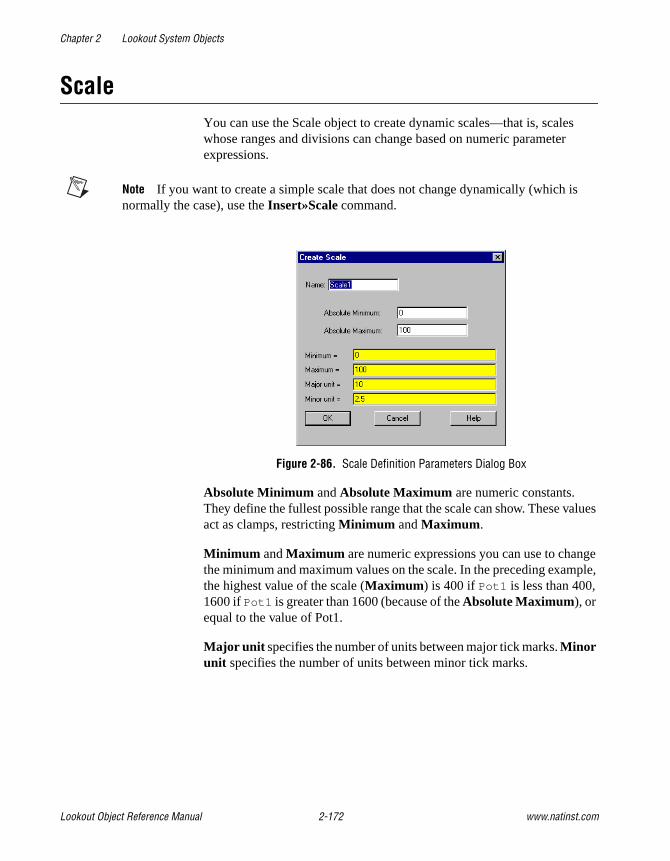
Chapter 2 Lookout System Objects
Lookout Object Reference Manual 2-172 www.natinst.com
ScaleYou can use the Scale object to create dynamic scales—that is, scales whose ranges and divisions can change based on numeric parameter expressions.
Note If you want to create a simple scale that does not change dynamically (which is normally the case), use the Insert»Scale command.
Figure 2-86. Scale Definition Parameters Dialog Box
Absolute Minimum and Absolute Maximum are numeric constants. They define the fullest possible range that the scale can show. These values act as clamps, restricting Minimum and Maximum .
Minimum and Maximum are numeric expressions you can use to change the minimum and maximum values on the scale. In the preceding example, the highest value of the scale (Maximum ) is 400 if Pot1 is less than 400, 1600 if Pot1 is greater than 1600 (because of the Absolute Maximum), or equal to the value of Pot1.
Major unit specifies the number of units between major tick marks. Minor unit specifies the number of units between minor tick marks.
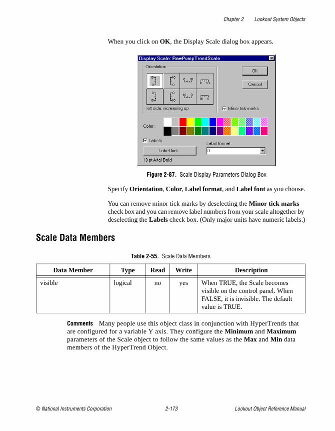
Chapter 2 Lookout System Objects
© National Instruments Corporation 2-173 Lookout Object Reference Manual
When you click on OK , the Display Scale dialog box appears.
Figure 2-87. Scale Display Parameters Dialog Box
Specify Orientation , Color, Label format , and Label font as you choose.
You can remove minor tick marks by deselecting the Minor tick marks check box and you can remove label numbers from your scale altogether by deselecting the Labels check box. (Only major units have numeric labels.)
Scale Data Members
Comments Many people use this object class in conjunction with HyperTrends that are configured for a variable Y axis. They configure the Minimum and Maximum parameters of the Scale object to follow the same values as the Max and Min data members of the HyperTrend Object.
Table 2-55. Scale Data Members
Data Member Type Read Write Description
visible logical no yes When TRUE, the Scale becomes visible on the control panel. When FALSE, it is invisible. The default value is TRUE.

Chapter 2 Lookout System Objects
Lookout Object Reference Manual 2-174 www.natinst.com
SequencerThe Sequencer object is a method for cycling through a collection of up to 100 differently configured ON/OFF states for your process.
Each Sequencer state has 26 logical outputs. Outputs left blank are considered OFF.
You set each output to ON or OFF for each state. You can also create jumps to skip from one state to another, or activate immediate jumps to a designated state.
Figure 2-88. Sequencer Definition Parameters Dialog Box
The States field activates the states you want in your sequence loop. If you set States to 5, the sequence object will pass through states 1 through 5 and then return to state 1 to repeat the cycle.
Notice that unused states can still be configured. In this way you can preconfigure special states, create subroutines, and so on. See the Programming the Sequencer section for further information on using this object.
Use Label to label each state.
The Time Limit parameter determines how long the Sequencer holds each state. If you leave this parameter blank, the Sequencer halts on that state until a Goto or Jump is activated, or the Time Limit parameter is changed.

Chapter 2 Lookout System Objects
© National Instruments Corporation 2-175 Lookout Object Reference Manual
Note When you set the Time Limit expression to reference a Lookout control, you must make sure the output of that control is either in HH:MM:SS format, or in days.
Outputs are the ON/OFF settings for each state.
Programming the SequencerLeft unmodified, the Sequencer cycles through the states selected in the States field of the Sequencer parameter configuration dialog box, beginning with state 1. If you enter 4 in the States field, the Sequencer will cycle through states 1—4 continuously, spending the amount of time in each state set by the Time limit .
Use the Goto data members to jump to a given state of the Sequencer immediately. Use the Jump data member to skip automatically from one state to a target state.
There is a tiny lag in state transition when you use the Jump data member. For instance, if you have a sequence cycling through states 1—8, and under some circumstances you want to skip states 5 and 6, moving directly from state 4 to state 7, set the jump5.7 data member to TRUE. When the Sequencer reaches the end of the state 4 Time limit , it switches to state 5, and then immediately jumps to state 7. State 5 will be active for a brief period (about 10 ms), however, which you should take into account in designing your sequences.
You can use sequential jumps if you choose. When you activate a jump from state 1 to state 5, for example, and also a jump from state 5 to state 9, the Sequencer skips from state 1 to state 9 with a 10 ms delay at state 5.
If you use a Jump or Goto data member to activate a state outside the number you selected in your States field, the Sequencer will continue to cycle through any states following the target state, until it either reaches a state with no set Time limit , or state 100.
If the Sequencer reaches a state with no set Time limit , it remains in that state until a Goto or Jump is activated, or until the Time Limit parameter is changed.
If the Sequencer reaches state 100, and if state 100 has a Time Limit set, the Sequencer cycles to state 1 at the end of that time, resuming its cycle inside the states defined by the States parameter.

Chapter 2 Lookout System Objects
Lookout Object Reference Manual 2-176 www.natinst.com
If you use a Goto or Jump data member to activate a state outside the ordinary cycle of a Sequencer object, you must use the Jump or Goto data members to return the sequence to its automatic cycle.
Sequencer Data MembersSee the Programming the Sequencer section for detailed information on using Sequencer data members.
Table 2-56. Sequencer Data Members
Data Member Type Read Write Description
A – Z logical yes no Sequencer outputs
Goto1 – Goto100 logical no yes When activated, forces Sequencer to go to the indicated state
Jump1.1 – Jump100.100
logical no yes When activated, jumps from the state indicated by the first number to the state indicated by the second number
StateName text yes no Reports the currently active state name (Label)
StateNumber text yes no Reports the sequence number (State No.) of the current state
Time numeric yes no Reports the current length of time the Sequencer has been in the current state
TimeLimit numeric yes no Reports the length of time set for the Sequencer to hold the current state
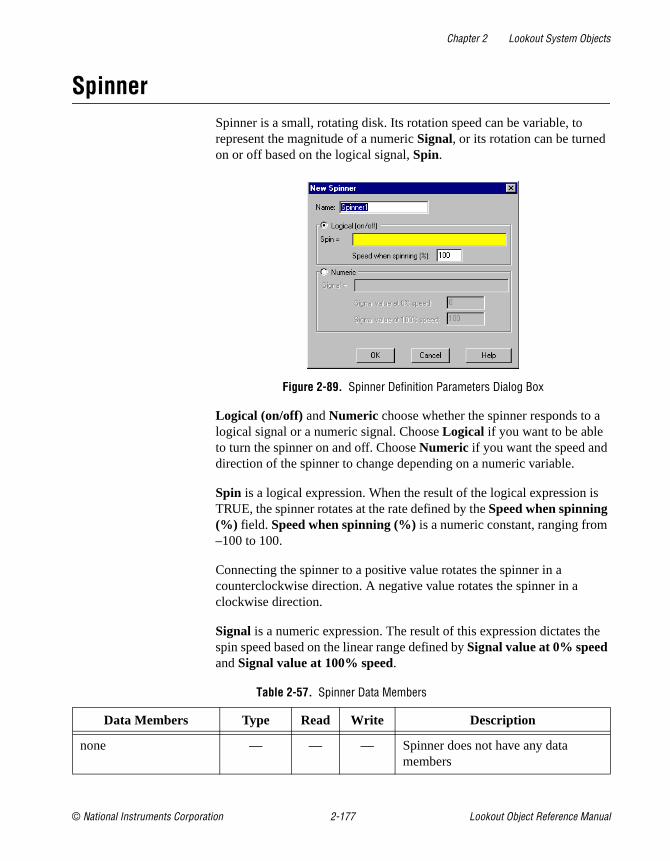
Chapter 2 Lookout System Objects
© National Instruments Corporation 2-177 Lookout Object Reference Manual
SpinnerSpinner is a small, rotating disk. Its rotation speed can be variable, to represent the magnitude of a numeric Signal, or its rotation can be turned on or off based on the logical signal, Spin.
Figure 2-89. Spinner Definition Parameters Dialog Box
Logical (on/off) and Numeric choose whether the spinner responds to a logical signal or a numeric signal. Choose Logical if you want to be able to turn the spinner on and off. Choose Numeric if you want the speed and direction of the spinner to change depending on a numeric variable.
Spin is a logical expression. When the result of the logical expression is TRUE, the spinner rotates at the rate defined by the Speed when spinning (%) field. Speed when spinning (%) is a numeric constant, ranging from –100 to 100.
Connecting the spinner to a positive value rotates the spinner in a counterclockwise direction. A negative value rotates the spinner in a clockwise direction.
Signal is a numeric expression. The result of this expression dictates the spin speed based on the linear range defined by Signal value at 0% speed and Signal value at 100% speed.
Table 2-57. Spinner Data Members
Data Members Type Read Write Description
none — — — Spinner does not have any data members

Chapter 2 Lookout System Objects
Lookout Object Reference Manual 2-178 www.natinst.com
Comments Spinners are typically used to represent flow through a line or to show a motor running.

Chapter 2 Lookout System Objects
© National Instruments Corporation 2-179 Lookout Object Reference Manual
SpreadsheetSpreadsheet permanently stores data to disk in spreadsheet files. You can log data on even and uneven intervals, when a data value changes, when an event occurs, or when any one of these things happen. Hence, you can implement complex logging criteria to meet almost any data storage need.
After each log, a new row is automatically added to the spreadsheet file. Lookout can log a new row of data approximately 10 times per second; however, the time stamps associated with each row are rounded to the nearest second.
Each spreadsheet file may store any number of data signals. Each data signal is assigned a spreadsheet column, beginning with column number two. The first column contains the date and time. The first row contains the expressions associated with the data in each column. You may create any number of Spreadsheet objects for a given process.
Figure 2-90. Spreadsheet Configuration Parameters Dialog Box
Name is the filename used to create a spreadsheet file. Lookout assigns a DOS filename to each spreadsheet file by adding the Type extension to the Name. Currently, Lookout supports only one Type: comma separated

Chapter 2 Lookout System Objects
Lookout Object Reference Manual 2-180 www.natinst.com
value format (.csv ). Most database and spreadsheet programs including Microsoft Excel directly read the .csv file format.
Because the Name parameter is a text expression field, you can create new .csv files with unique names dynamically. This is especially useful for recording batch processing data. The definition dialog box Figure 2-86 is configured so that an operator can enter a batch name using a TextEntry object before the batch is started. The text expression appends the filename to the specified path, C:\BATLOG\ . So if the operator enters a file name like BATCH71, then the full path name would be C:\BATLOG\BATCH71.CSV. When the BatchRun logical signal goes TRUE, Lookout creates the new .csv file and begins writing to it. When BatchRun goes FALSE, logging ends, leaving a comprehensive log of all data associated with the batch.
This example forces Lookout to store the .csv file in a particular directory because it specifies a full path name. If you enter a relative pathname like "\BATLOG\"&TextEntry1 , the file is located in that subdirectory of the identified Directory tree location. So, for example, the full path name of the file might be C:\LOOKOUT\1995\SEP\BATLOG\BATCH71.CSV .
If you enter just a filename such as "DATA" , the file location is based on the Lookout directory. For example, the full path name of the file might be C:\LOOKOUT\1995\SEP\DATA.CSV .
If you select Daily, Lookout creates a new file and subdirectory every day in which to store the data. If you select Monthly , Lookout creates a new file and subdirectory every month in which to store the data. If you select Yearly, Lookout creates a new file and subdirectory every year. Perpetual files are stored in the root directory as specified by your Data files location parameter.
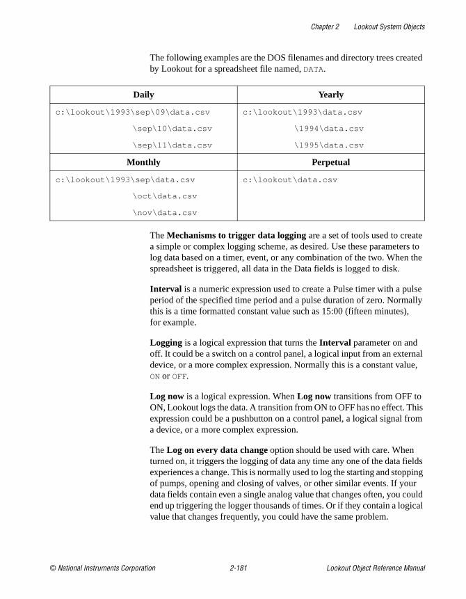
Chapter 2 Lookout System Objects
© National Instruments Corporation 2-181 Lookout Object Reference Manual
The following examples are the DOS filenames and directory trees created by Lookout for a spreadsheet file named, DATA.
The Mechanisms to trigger data logging are a set of tools used to create a simple or complex logging scheme, as desired. Use these parameters to log data based on a timer, event, or any combination of the two. When the spreadsheet is triggered, all data in the Data fields is logged to disk.
Interval is a numeric expression used to create a Pulse timer with a pulse period of the specified time period and a pulse duration of zero. Normally this is a time formatted constant value such as 15:00 (fifteen minutes), for example.
Logging is a logical expression that turns the Interval parameter on and off. It could be a switch on a control panel, a logical input from an external device, or a more complex expression. Normally this is a constant value, ONor OFF.
Log now is a logical expression. When Log now transitions from OFF to ON, Lookout logs the data. A transition from ON to OFF has no effect. This expression could be a pushbutton on a control panel, a logical signal from a device, or a more complex expression.
The Log on every data change option should be used with care. When turned on, it triggers the logging of data any time any one of the data fields experiences a change. This is normally used to log the starting and stopping of pumps, opening and closing of valves, or other similar events. If your data fields contain even a single analog value that changes often, you could end up triggering the logger thousands of times. Or if they contain a logical value that changes frequently, you could have the same problem.
Daily Yearly
c:\lookout\1993\sep\09\data.csv
c:\lookout\1993 \sep\10\data.csv
c:\lookout\1993 \sep\11\data.csv
c:\lookout\1993\data.csv
c:\lookout \1994\data.csv
c:\lookout \1995\data.csv
Monthly Perpetual
c:\lookout\1993\sep\data.csv
c:\lookout\1993 \oct\data.csv
c:\lookout\1993 \nov\data.csv
c:\lookout\data.csv

Chapter 2 Lookout System Objects
Lookout Object Reference Manual 2-182 www.natinst.com
The Data fields window lists all expressions that have been entered for logging in the order of their field number.
The Save button saves your new or modified expression in the Data fields window along with a new field number if any. Normally, Data fields contain simple expressions like PLC1.Tanklevel .
The Delete button deletes the currently selected expression from the data fields list.
The Format option specifies the numeric format assigned to the currently selected numeric expression when it is logged to disk. This has no effect on logical or text expressions.
Field indicates the number of the currently selected data field.
Note Field numbers should not be modified after data has been stored or the data will not appear under correct headers until a new file is created.
Spreadsheet Data Members
Table 2-58. Spreadsheet Data Members
Data Members Type Read Write Description
logged logical yes no Spreadsheet file update pulse. The Spreadsheet object generates this logical pulse with a pulse duration of zero after each successful log.

Chapter 2 Lookout System Objects
© National Instruments Corporation 2-183 Lookout Object Reference Manual
SqlExecSqlExec is an object Lookout uses to communicate with the ODBC driver. ODBC allows Lookout to connect to any database that supports ODBC.
SqlExec connects to ODBC using the standard ODBC calls, and queries the database using SQL statements. The data, if any, is returned in the object data members.
Figure 2-91. SqlExec Configuration Parameters Dialog Box
Data Source specifies the Data Source Name (DSN) as well as any other parameters needed by the ODBC driver to make the connection to the data source. For example if you want to connect to Excel 4.0, use:
"DSN=Excel Files; DBQ=C:\pathname;"
SQL is the SQL string you want to pass to the ODBC driver.
Alarm Priority determines the priority level of object-generated alarms.
Buffer SQL tells the SqlExec object to buffer any entries that fail for that object. An entry consists of the Data Source string and the SQL string.While Lookout does install a Lookout ODBC driver, you must manually create your own data source in order to access the Citadel database using ODBC. Consult Chapter 8, Structured Query Language, of the Lookout Developer’s Manual for information on how to create your Lookout data source.

Chapter 2 Lookout System Objects
Lookout Object Reference Manual 2-184 www.natinst.com
Note Some applications are not completely ODBC compliant. If you plan to use Microsoft Query, Microsoft Access, or Microsoft Visual Basic, ensure that the maximum column name length does not exceed 62 characters. These applications cannot handle longer names. Applications that are completely ODBC-compliant can handle names up to 126 characters long. All traces whose names exceed the maximum column name length are excluded from queries.
Because Lookout objects may include network path information in their names, and because you can arrange Lookout objects in hierarchies inside your processes, you may find it easy to exceed the 62 and 126 character limitations of ODBC. Consideration given to naming and organizing objects can minimize the risk of encountering this difficulty.
SqlExec Data Members
Table 2-59. SqlExec Data Members
Data Member Type Read Write Description
c1 – c65535 numeric yes no Value of the nth column in the row returned by ODBC.
c1.logical – c65535.logical
logical yes no Value of the nth column in the row returned by ODBC.
c1.txt – c65535.txt text yes no Value of the nth column in the row returned by ODBC.
Execute logical no yes Executes the submitted SQL statement when it receives a change from low to high.
Failure logical yes no High if the last submitted query failed.
ReadOnly logical yes yes If TRUE, opens the file in read only mode.If FALSE, opens the file in read write mode.
Status logical yes no High when the object is processing a query.
Chapter 2 Lookout System Objects
© National Instruments Corporation 2-185 Lookout Object Reference Manual
SqlExec CommentsThe placement of the data in the data members is determined by the SQL string. If you submit the SQL string
"select Album, Artist, NumTracks from cdTable
where NumTracks>5"
the return value for Album is contained in the data member c1.txt , Artist in c2.txt , and NumTracks in c3 . This value is displayed according to the data member you choose—Text, Logical, or Numeric. If you connect both to c1 and c1.txt , you are connecting to the same value twice. In these circumstances, the value is represented in a different form.
A select statement only returns the first row that it encounters with the matching criteria. An update statement updates all the rows it encounters with the matching criteria.
If you connect your SqlExec object to a timer that pulses faster than several times per second, Lookout may become so busy handling SQL queries that it becomes unresponsive to user input from the mouse or keyboard.
Comma Separated Value (CSV) files are supported in ODBC. You can append data to them using the SQL insert command, but you cannot update records using the SQL update command. This is a limitation of the CSV file format.
• Excel files are accessible through ODBC, but they do have some unusual properties.
• If you use SqlExec to update an Excel 5.0 or greater workbook, the workbook must be closed and have multi-user editing turned off.
• If you are just trying to read from a workbook using a select query, then multi-user editing can be on, and the file can be opened or closed.
• If you try to access an Excel 5.0 or greater workbook while it is open and multi-user editing is off, Lookout locks up until the Excel file is closed. This is caused by a problem in the Excel ODBC driver.
• If you are using Excel 4.0 you can update or read from the worksheet only when it is closed. If you try to access an Excel 4.0 worksheet while it is open, you will receive an alarm in Lookout.
Citadel is also accessible through ODBC, but is opened exclusively in read-only mode to protect the integrity of the data.
The following table lists a few sample DSN and SQL strings for connecting to different types of databases through ODBC. Notice that they differ

Chapter 2 Lookout System Objects
Lookout Object Reference Manual 2-186 www.natinst.com
slightly from database to database. Remember that Data Source and SQL are expressions. If you enter a string into the expression box, the string must be properly set off by quotes. The strings in the following table appear exactly as you would type them into Lookout.
Database Type Data Source String SQL String
CSV DSN=Text Files;
DBQ= c:\ldev\ald2csv;
"select Priority,""Date &
Time," "Description from
alarm.csv where
Priority = 4"
Excel 4.0 DSN=Excel Files;
DBQ= c:\ldev\ald2csv;
select Priority," "Date &
Time," "Alarm Codes
(Set:Reset:Acknowledge",
"Description from alarm.xls
alarm where Priority = 4"
Excel 5.0 DSN=Excel Files; "select Priority," "Date &
Time," "Alarm Code
(Set:Reset:Acknowledged),"
"Description from Table1
where Priority = 4"
MS Access DSN=MS Access 7.0
Database;
DBQ=c:\My Documents\
compact.mdb;
"select Title, AlbumID,
Length from tracks where
TrackID = 7"
Citadel DSN=Citadel 32-bit; "select Interval,
LocalTime," "Waves.Square"
"from Traces where
Interval = 0:1 and
LocalTime >" "2/14/97
14:34:30"

Chapter 2 Lookout System Objects
© National Instruments Corporation 2-187 Lookout Object Reference Manual
SQL Command BufferingThe SQLExec object can create a buffer for SQL commands so that commands are not lost if the connection to the database is temporarily lost. Buffering stores failed commands in a file so that they can be resubmitted once the connection to the database is reestablished.
If you check the Buffer SQL checkbox in the Create SQL dialog box, the object buffers entries that fail for the following reasons.
• Unable to connect to data source: error code 08001.
• Connection in use: error code 08002.
• Communication link failure: error code 08S01.
• Drivers SQLAllocEnv failed: error code IM004.
• Drivers SQLAllocConnect Failed: error code IM005.
• Unable to load translation DLL: error code IM009.
Entries are not buffered for any other error codes. This is to prevent entries that always cause an error from being buffered, such as a syntax error in an SQL string.
You should only enable buffering for SqlExec objects that are inserting new data into a database, such as an SQL insert command.
When entries are being buffered, they are buffered according to the data source with which they are trying to connect. This prevents an SqlExec object being buffered for an Excel data source from blocking an SqlExec object connected to an MS Access data source.
Separating the buffers by data source also keeps entries from different SqlExec objects trying to connect to the same data source in their proper chronological order.
If an SqlExec object has to buffer data, it keeps the data in a directory called dsndata in your Lookout data directory. The data is kept in a .csv file, you can view in Excel. Do not try to view these files while Lookout is running.
Once an object starts buffering, it buffers all subsequent entries to that data source for all objects that have buffering turned on. Because of this, an entry with a syntax or other error that should not be buffered, can be buffered. If this occurs, the buffering system discards that entry after the entry is passed to ODBC and ODBC returns an error. You are not notified when the entry is discarded.

Chapter 2 Lookout System Objects
Lookout Object Reference Manual 2-188 www.natinst.com
If an object has buffering turned off, and that data source is currently being buffered, then that entry bypasses the buffer entirely. It then either succeeds or fails according to the state of the connection to the data source.
If a data source has buffered data, the buffering system automatically tries to reconnect to the data source periodically. Once it connects, it clears the buffer by periodically de-queuing the first few entries and sending them to ODBC.
During buffering, the Failure data member has a slightly different meaning. If it is high, then the first entry in the buffer failed and was kept in the buffer. If it is low it means that the first entry in the buffer was successfully submitted to ODBC, and objects are still being buffered until the buffer can be cleared.
If you are creating and testing a process file, you may accumulate a large amount of buffered data in the dsndata directory. You can safely delete this directory when Lookout is not running. You will lose all the buffered data, but the SqlExec objects then loads with no errors or alarms.
SqlExec Status MessagesODBC Environment not allocated. No buffering will occur
Indicates that memory could not be allocated for the connection to ODBC. This only occurs if your system is about to run out of memory. No buffering occurs if this alarm is set. Data that has already been buffered is not lost.
ODBC(32).DLL Not loaded
Indicates that the DLL could not be loaded. No buffering can occur if this alarm is set. Data that has already been buffered, is not lost.
Data Source Name: Objects are being buffered for this data source
This indicates which data sources are being buffered. Once the buffered entries have been cleared, the alarm ceases.
Incorrect data source string, check syntax
This means that the Data Source string is missing the DSN=driver name; pair.
SqlExec displays any error messages that it receives from ODBC as an alarm. If the error is an error that should cause buffering, the status message indicates whether the entry was buffered or not buffered. Each message

Chapter 2 Lookout System Objects
© National Instruments Corporation 2-189 Lookout Object Reference Manual
returned by ODBC belongs to the ODBC group. Some of the more common ODBC error messages are:
[Not Buffered] 37000/-3100: [Microsoft][Driver Name] Syntax error in query expression ‘ …’
The SQL string has a syntax error in it.
[Not Buffered] S1000/-1811 [Microsoft][Driver Name]Couldn’t find file ‘(unknown)’
This usually means that your data source expression is incorrect, or you have ODBC configured incorrectly for that data source expression, such as trying to connect to an Excel 5.0 workbook your ODBC Excel driver set up for Excel 4.0 worksheets. Check the data source expression and the configuration of the ODBC driver.
[Not Buffered] 42000/-1809 [Microsoft][Driver Name]can’t update. Database or object is read-only.
The file has been opened in read-only mode, but you are trying to write to it. If you have the data member ReadOnly set to TRUE, set it to FALSE. For some drivers, you can specify in the ODBC administration tool that all files opened by that driver should be opened in read-only mode. Check the ODBC configuration if you have ReadOnly set to FALSE and are still getting this error. For some ODBC drivers (such as Citadel) the file is always opened in read-only mode to protect the integrity of the files.
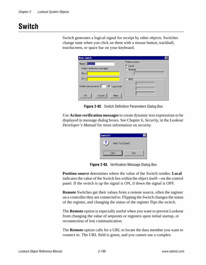
Chapter 2 Lookout System Objects
Lookout Object Reference Manual 2-190 www.natinst.com
SwitchSwitch generates a logical signal for receipt by other objects. Switches change state when you click on them with a mouse button, trackball, touchscreen, or space bar on your keyboard.
Figure 2-92. Switch Definition Parameters Dialog Box
Use Action verification messages to create dynamic text expressions to be displayed in message dialog boxes. See Chapter 6, Security, in the Lookout Developer’s Manual for more information on security.
Figure 2-93. Verification Message Dialog Box
Position source determines where the value of the Switch resides. Local indicates the value of the Switch lies within the object itself—on the control panel. If the switch is up the signal is ON, if down the signal is OFF.
Remote Switches get their values from a remote source, often the register on a controller they are connected to. Flipping the Switch changes the status of the register, and changing the status of the register flips the switch.
The Remote option is especially useful when you want to prevent Lookout from changing the value of setpoints or registers upon initial startup, or reconnection of lost communication.
The Remote option calls for a URL to locate the data member you want to connect to. The URL field is green, and you cannot use a complex
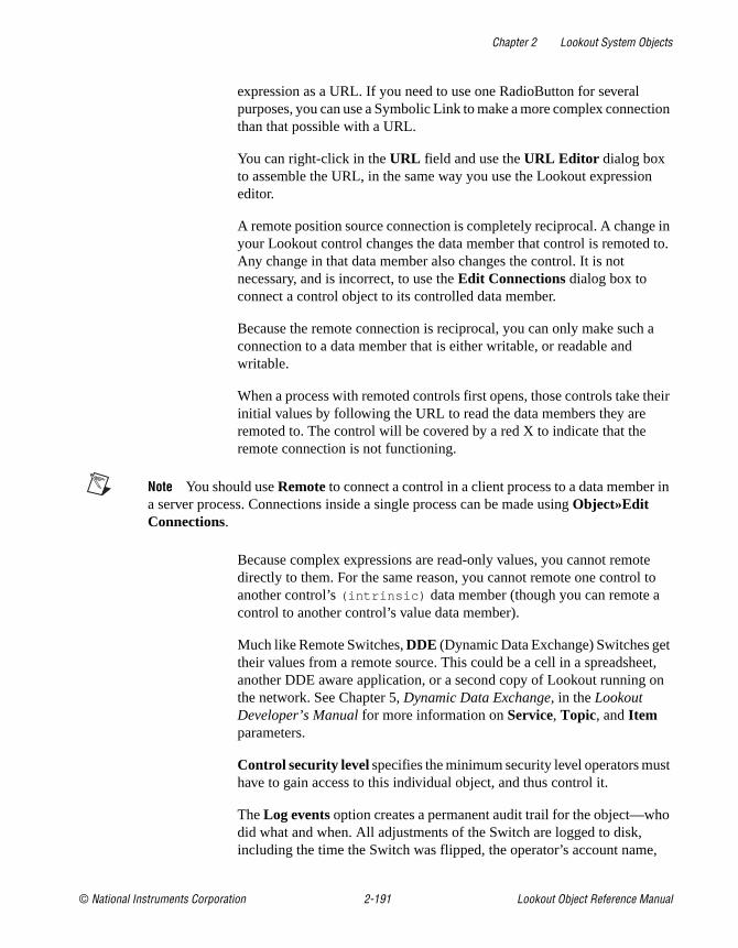
Chapter 2 Lookout System Objects
© National Instruments Corporation 2-191 Lookout Object Reference Manual
expression as a URL. If you need to use one RadioButton for several purposes, you can use a Symbolic Link to make a more complex connection than that possible with a URL.
You can right-click in the URL field and use the URL Editor dialog box to assemble the URL, in the same way you use the Lookout expression editor.
A remote position source connection is completely reciprocal. A change in your Lookout control changes the data member that control is remoted to. Any change in that data member also changes the control. It is not necessary, and is incorrect, to use the Edit Connections dialog box to connect a control object to its controlled data member.
Because the remote connection is reciprocal, you can only make such a connection to a data member that is either writable, or readable and writable.
When a process with remoted controls first opens, those controls take their initial values by following the URL to read the data members they are remoted to. The control will be covered by a red X to indicate that the remote connection is not functioning.
Note You should use Remote to connect a control in a client process to a data member in a server process. Connections inside a single process can be made using Object»Edit Connections.
Because complex expressions are read-only values, you cannot remote directly to them. For the same reason, you cannot remote one control to another control’s (intrinsic) data member (though you can remote a control to another control’s value data member).
Much like Remote Switches, DDE (Dynamic Data Exchange) Switches get their values from a remote source. This could be a cell in a spreadsheet, another DDE aware application, or a second copy of Lookout running on the network. See Chapter 5, Dynamic Data Exchange, in the Lookout Developer’s Manual for more information on Service, Topic, and Item parameters.
Control security level specifies the minimum security level operators must have to gain access to this individual object, and thus control it.
The Log events option creates a permanent audit trail for the object—who did what and when. All adjustments of the Switch are logged to disk, including the time the Switch was flipped, the operator’s account name,

Chapter 2 Lookout System Objects
Lookout Object Reference Manual 2-192 www.natinst.com
and the direction the Switch was flipped. See Chapter 7, Logging Data and Events, in the Lookout Developer’s Manual for more information on event logging.
You can replace the standard switch types with custom graphic symbols. If you decide to use custom graphics, you must specify both symbol parameters, On and Off . See Chapter 2, Graphics, in the Lookout Developer’s Manual for more information on creating custom graphic symbols and the use of transparent pixels.
Switch Data Members
Table 2-60. Switch Data Members
Data Members Type Read Write Description
(implicit) logical yes no Switch Position
enable logical no yes If TRUE (the default), enables DDE. If FALSE, disables DDE. The default value is ON. This input is ignored for non-DDE TextEntry objects.
reset logical no yes While this value equals TRUE, the control will be set to the value in resetvalue .
resetvalue numeric no yes Sets the value a control will take when the reset data member transitions from FALSE to TRUE.

Chapter 2 Lookout System Objects
© National Instruments Corporation 2-193 Lookout Object Reference Manual
Comments If a switch with more than two positions is needed, use a Pot object instead.
Related Objects Pushbutton, Pot
value numeric yes yes The current value of the control. If you have remoted this control, then value is the current value of the position source.
visible logical no yes When FALSE, the switch object cannot be seen on the display panel. When TRUE, the Switch can be seen and controlled.
Table 2-60. Switch Data Members (Continued)
Data Members Type Read Write Description

Chapter 2 Lookout System Objects
Lookout Object Reference Manual 2-194 www.natinst.com
Symbolic LinksA Symbolic Link is a Lookout object you use to make certain kinds of remote connections easier and more efficient. This object can also be used to manage failover redundancy in Lookout 4. (Redundancy is not implemented in the Lookout 4 Preview.)
The Symbolic Link serves as a flexible intermediary between separate processes whether they are running on one computer or on different computers.
Create a Symbolic Link using the Lookout object browser. Right-click on the process or folder into which you want to insert the new Symbolic Link. The following dialog box appears.
The Symbolic Link can represent either a static or a dynamic source. The Static source is a URL pointing to a computer, process, folder, or object running in some instance of Lookout on your network. A typical Symbolic Link set to a process appears in the following illustration.
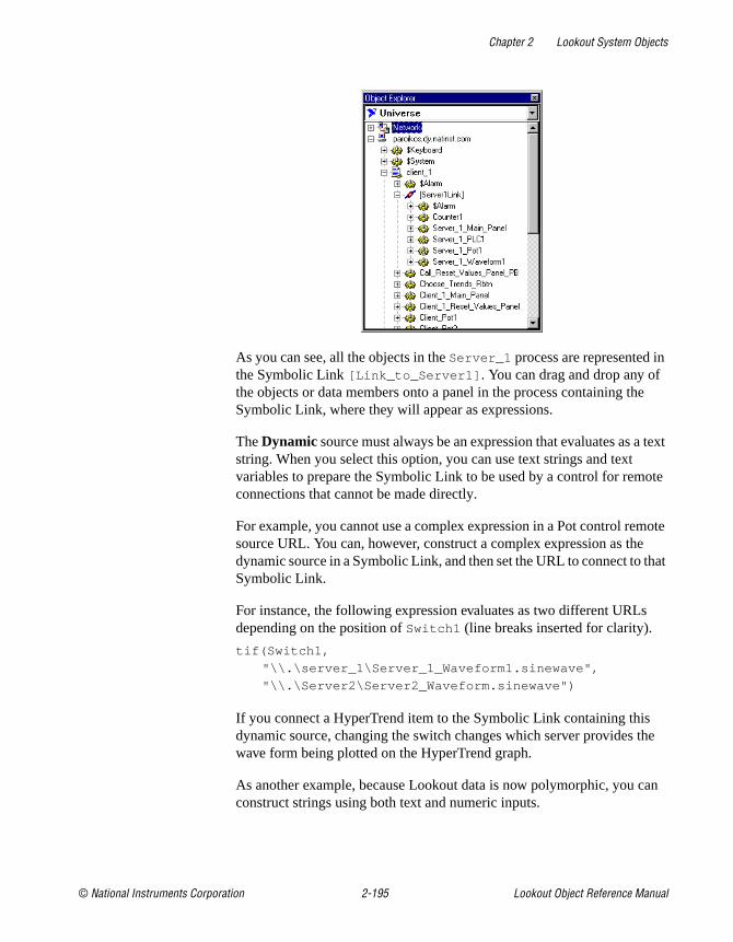
Chapter 2 Lookout System Objects
© National Instruments Corporation 2-195 Lookout Object Reference Manual
As you can see, all the objects in the Server_1 process are represented in the Symbolic Link [Link_to_Server1] . You can drag and drop any of the objects or data members onto a panel in the process containing the Symbolic Link, where they will appear as expressions.
The Dynamic source must always be an expression that evaluates as a text string. When you select this option, you can use text strings and text variables to prepare the Symbolic Link to be used by a control for remote connections that cannot be made directly.
For example, you cannot use a complex expression in a Pot control remote source URL. You can, however, construct a complex expression as the dynamic source in a Symbolic Link, and then set the URL to connect to that Symbolic Link.
For instance, the following expression evaluates as two different URLs depending on the position of Switch1 (line breaks inserted for clarity).
tif(Switch1,
"\\.\server_1\Server_1_Waveform1.sinewave",
"\\.\Server2\Server2_Waveform.sinewave")
If you connect a HyperTrend item to the Symbolic Link containing this dynamic source, changing the switch changes which server provides the wave form being plotted on the HyperTrend graph.
As another example, because Lookout data is now polymorphic, you can construct strings using both text and numeric inputs.

Chapter 2 Lookout System Objects
Lookout Object Reference Manual 2-196 www.natinst.com
For example, if you create Pot1 with a minimum of 0, a maximum of 9, and an interval of 1, you can use the expression "Modbus1.4001" & Pot1
as the entry for the Dynamic option in a Symbolic Link.
You can then use the Symbolic Link to connect a control to Modbus data members 40010-40019 , depending on the setting of Pot1.
While you could not directly remote your control to that range of Modbus data members, you can make a remote connection from that control to the Symbolic Link using that dynamic expression.
If you connect the Dynamic expression to a data table, you have a nearly unlimited ability to have one object control a large number of data members, either through a cursor control or a radio button control.

Chapter 2 Lookout System Objects
© National Instruments Corporation 2-197 Lookout Object Reference Manual
$System$System is a global object. It makes global Lookout data such as the currently logged in user name and security level available for use in your process. You can use $System data members just like other object data members.
The seclevel data member is always an integer value between 1 and 10. This number represents the Lookout security level of the user currently logged in. For more information about Lookout security levels, see Chapter 6, Security, in the Lookout Developer’s Manual.
The time data member represents the current date and time of the system. Like all time values in Lookout, this is a floating point number in which the integer represents the date and the fraction represents the time of day. You can use the various Lookout date and time numeric formats to view this value in the most convenient format. This data member updates itself every minute, on the minute. It also updates itself immediately after it is created or when its process is opened.
The username data member is the account name of the user currently logged in. For more information about Lookout security accounts, see Chapter 6, Security, in the Lookout Developer’s Manual.
$System Data Members
Table 2-61. $System Data Members
Data Member Type Read Write Description
NetworkStatus text yes no Reports the status of the last network transaction of your computer. You may need to use this data member in conjunction with a Sample object to keep track of high levels of network activity with many I/O points.
seclevel numeric yes no Security level of the user currently logged in
time numeric yes no Current operating system time
username text yes no Name of the user currently logged in

Chapter 2 Lookout System Objects
Lookout Object Reference Manual 2-198 www.natinst.com
TextEntryWith TextEntry you can manually enter textual notes with the keyboard. These notes may contain any combination of numeric and alphanumeric characters; however, the result of your entry is converted to a text value. Just like any other text expression in Lookout, your note can be logged to disk, connected to other data members that accept text signals, and so on. The note is saved and displayed as a single line entry—you cannot embed carriage returns into the message.
Figure 2-94. TextEntry Parameters Dialog Box
Entry prompt is the text that appears at the top of the text entry dialog box when an operator selects the text entry pushbutton.
Text source determines where the user-entered text resides. Local indicates the user-entered text lies within the object itself—on the control panel.
Remote indicates that the user-entered text resides in a remote source, such as a text expression or another TextEntry object.
The Remote option calls for a URL to locate the data member you want to connect to. The URL field is green, and you cannot use a complex expression as a URL. If you need to use one RadioButton for several purposes, you can use a Symbolic Link to make a more complex connection than that possible with a URL.

Chapter 2 Lookout System Objects
© National Instruments Corporation 2-199 Lookout Object Reference Manual
You can right-click in the URL field and use the URL Editor dialog box to assemble the URL, in the same way you use the Lookout expression editor.
A remote position source connection is completely reciprocal. A change in your Lookout control changes the data member that control is remoted to. Any change in that data member also changes the control. It is not necessary, and is incorrect, to use the Edit Connections dialog box to connect a control object to its controlled data member.
Because the remote connection is reciprocal, you can only make such a connection to a data member that is either writable, or readable and writable.
When a process with remoted controls first opens, those controls take their initial values by following the URL to read the data members they are remoted to. The control will be covered by a red X to indicate that the remote connection is not functioning.
Note You should use Remote to connect a control in a client process to a data member in a server process. Connections inside a single process can be made using Object»Edit Connections.
Because complex expressions are read-only values, you cannot remote directly to them. For the same reason, you cannot remote one control to another control’s (intrinsic) data member (though you can remote a control to another control’s value data member).
Much like Remote TextEntry objects, DDE TextEntry objects get their values from a remote source. This is the option you use to tie the text to a cell in a spreadsheet, a database lookup table, or any DDE aware application—including a second copy of Lookout running on the network. See Chapter 5, Dynamic Data Exchange, in the Lookout Developer’s Manual for more detailed information on Service, Topic and Item.
Note The last DDE parameters used on any object automatically become the default values for any new DDE object.
Control security level specifies the minimum security level operators must have to gain access to this individual object, and thus control it.
The Log events option creates a permanent audit trail for the object—who did what and when. When selected, all text entries in this object are logged to disk. Each entry includes the time of the entry, the operator’s account

Chapter 2 Lookout System Objects
Lookout Object Reference Manual 2-200 www.natinst.com
name, and what entry was made. See Chapter 7, Logging Data and Events, in the Lookout Developer’s Manual for more information on event logging.
Lookout presents the following display parameters dialog box after you define the object. It lets you define the text font and presentation style.
Figure 2-95. TextEntry Display Parameters Dialog Box
TextEntry Data Members
Table 2-62. TextEntry Data Members
Data Members Type Read Write Description
(implicit) text yes no Current, user-entered text
enable logical no yes If TRUE (the default), enables DDE. If FALSE, disables DDE. The default value is ON. This input is ignored for non-DDE TextEntry objects.
reset logical no yes While this value equals TRUE, the control will be set to the value in resetvalue .

Chapter 2 Lookout System Objects
© National Instruments Corporation 2-201 Lookout Object Reference Manual
resetvalue numeric no yes Sets the value a control will take when the reset data member transitions from FALSE to TRUE.
value numeric yes yes The current value of the control. If you have remoted this control, then value is the current value of the position source.
Table 2-62. TextEntry Data Members
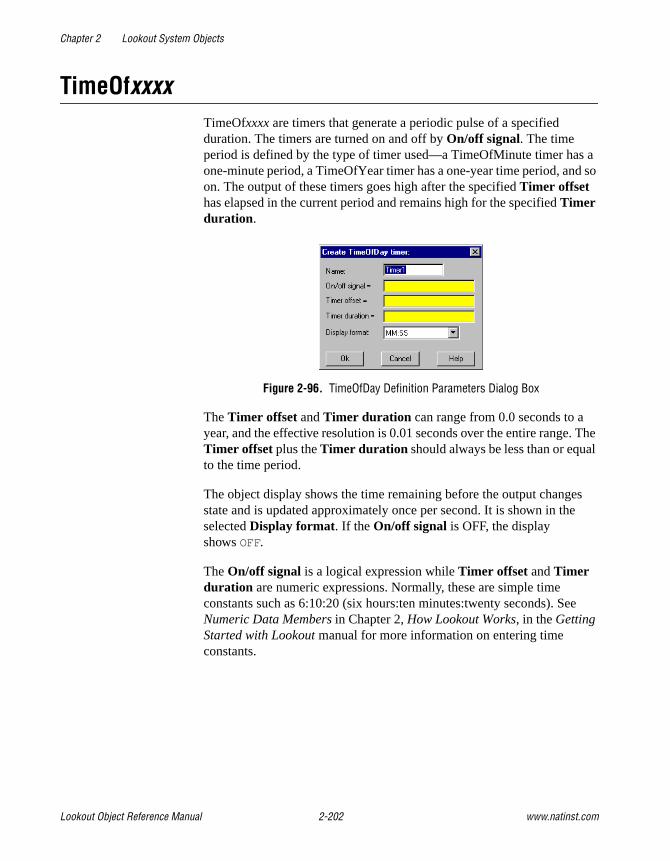
Chapter 2 Lookout System Objects
Lookout Object Reference Manual 2-202 www.natinst.com
TimeOfxxxxTimeOfxxxx are timers that generate a periodic pulse of a specified duration. The timers are turned on and off by On/off signal. The time period is defined by the type of timer used—a TimeOfMinute timer has a one-minute period, a TimeOfYear timer has a one-year time period, and so on. The output of these timers goes high after the specified Timer offset has elapsed in the current period and remains high for the specified Timer duration .
Figure 2-96. TimeOfDay Definition Parameters Dialog Box
The Timer offset and Timer duration can range from 0.0 seconds to a year, and the effective resolution is 0.01 seconds over the entire range. The Timer offset plus the Timer duration should always be less than or equal to the time period.
The object display shows the time remaining before the output changes state and is updated approximately once per second. It is shown in the selected Display format. If the On/off signal is OFF, the display showsOFF.
The On/off signal is a logical expression while Timer offset and Timer duration are numeric expressions. Normally, these are simple time constants such as 6:10:20 (six hours:ten minutes:twenty seconds). See Numeric Data Members in Chapter 2, How Lookout Works, in the Getting Started with Lookout manual for more information on entering time constants.

Chapter 2 Lookout System Objects
© National Instruments Corporation 2-203 Lookout Object Reference Manual
Figure 2-97. TimeOfDay Display Parameters Dialog Box
Timeofxxxx Data Members
Comments TimeOfxxxx can be used in place of Pulse objects when the pulse needs to be synchronized with the clock—if a pump should only be allowed to run between the hours of 8:00 and 17:00 each day, the TimeOfDay timer should be used.
Related Objects DelayOff, DelayOn, Interval, OneShot, Pot
Table 2-63. TimeOfxxxx Data Members
Data Members Type Read Write Description
(implicit) logical yes no Logical timer value

Chapter 2 Lookout System Objects
Lookout Object Reference Manual 2-204 www.natinst.com
XBarRThe XBarR object class is one of the Lookout Statistical Process Control (SPC) tools and can play an important role in your Total Quality Management (TQM) program. This object class graphically displays an X-Bar chart and/or an R chart for a given signal. These control charts (also called mean and range charts, respectively) enable you to track your process to determine if it is about to go out of control and needs corrective attention.
Figure 2-98. XBarR Definition Parameters Dialog Box
The XBarR object reads the Observed signal value any time the Observed trigger transitions from OFF to ON. When the object collects the specified Number of observations per sample (2 – 25), it calculates the mean and range and plots them on their respective charts. Each chart plots the specified Number of samples to display.
X-bar Chart limits and R Chart limits can be specified or calculated, as you choose. The object continually calculates chart limits based on new samples as they are accumulated. These calculated limits enable you to track your process for a time to determine limit settings that your process is capable of operating within. Once you know what limits your process can normally handle, you can specify the chart limit parameters by entering them directly.
LCL and UCL chart limits identify the lower and upper control limits. These outer limits generally define the range of process acceptability. CL identifies the centerline. For the X-bar chart, the centerline is the mean

Chapter 2 Lookout System Objects
© National Instruments Corporation 2-205 Lookout Object Reference Manual
of sample means. For the R chart, the centerline is the average of the sample ranges.
You can display X-bar charts and R charts in various colors with different label styles and grid spacing.
Figure 2-99. XBarR Display Parameters Dialog Box
When you enter the LCL , UCL and CL chart limit parameters for a chart, the entered values represent the limits shown on the chart. The following X-Bar Chart shows upper control limit, center line, and lower control limit entered as constants. The chart shows that the majority of the last 30 samples are running a bit under the centerline, suggesting that the process may need to be adjusted. The calculated control limits, shown below the graph, indicate new limits that might be used based on the current plotted samples.

Chapter 2 Lookout System Objects
Lookout Object Reference Manual 2-206 www.natinst.com
Figure 2-100. X-Bar Chart Showing Upper Control Limit, Center Line, and Lower Control Limits
If you leave one or more of the limit parameters blank for a chart in the definition parameters dialog box, the chart shows its calculated limits. As you can see in the following R chart, the calculated limits and the plotted limits are the same.
Figure 2-101. R Chart Showing Upper Control Limit, Center Line, and Lower Control Limits as Calculated Based on Plotted Samples

Chapter 2 Lookout System Objects
© National Instruments Corporation 2-207 Lookout Object Reference Manual
XBarR Data Members
Table 2-64. XBarR Data Members
Data Members Type Read Write Description
R_ChartMax numeric yes no Identifies the top of the Range chart graph (the value of the plotted line when it is at 100 percent of the Y axis). The object recalculates this value as each new sample is read to ensure that the plotted line is always visible on the graph.
R_ChartMin numeric yes no Identifies the bottom of the Range chart graph (the value of the plotted line when it is at zero percent of the Y axis). The object recalculates this value as each new sample is read to ensure that the plotted line is always visible on the graph.
R_CL numeric yes no Centerline of range chart showing average of sample ranges calculated as follows:
R_LCL numeric yes no Lower control limit of Range chart, calculated using the sampled data as follows:
where is from any standard 3-sigma control factors table
R_Sample numeric yes no Calculated range, , of the last completed sample of observations, defined as the difference between the maximum and minimum observations in the sample.
R
R
n
i
i
n
= =∑
1
LCL D R= 3
D3
R

Chapter 2 Lookout System Objects
Lookout Object Reference Manual 2-208 www.natinst.com
R_UCL numeric yes no Upper control limit of Range chart, calculated using the sampled data as follows:
where is from any standard 3-sigma control factors table
Visible logical yes yes When TRUE, the X-bar and R charts become visible on the control panel. When FALSE, they are invisible. The default value is TRUE.
Xbar_ChartMax numeric yes no Identifies the top of the X-bar chart graph (the value of the plotted line if it is at 100 percent of the Y axis). The object recalculates this value as each new sample is read to ensure that the plotted line is always visible on the graph.
Xbar_ChartMin numeric yes no Identifies the bottom of the X-bar chart graph (the value of the plotted line if it is at zero percent of the Y axis). The object recalculates this value as each new sample is read to ensure that the plotted line is always visible on the graph.
Xbar_CL numeric yes no Centerline of X-bar chart showing the mean of sample means, calculated as follows:
Table 2-64. XBarR Data Members (Continued)
Data Members Type Read Write Description
UCL D R= 4
D4
x
x
n
i
i
n
= =∑
1

Chapter 2 Lookout System Objects
© National Instruments Corporation 2-209 Lookout Object Reference Manual
Related Objects Average, Histogram, Maximum, Minimum, Sample
Related Functions Avg, Max, Min, Stdev, Stdevp, Sum, Var, VarpRefer to the Lookout Developer’s Manual for more information.
Xbar_LCL numeric yes no Lower control limit of X-bar chart, calculated as follows:
where is from any standard 3-sigma control factors table
Xbar_Sample numeric yes no Calculated mean of the last completed sample of observations, where
Xbar_UCL numeric yes no Upper control limit of X-bar chart, calculated as follows:
where is from any standard 3-sigma control factors table
Table 2-64. XBarR Data Members (Continued)
Data Members Type Read Write Description
LCL x A R= − 2
A2
x
x
n
i
i
n
= =∑
1
UCL x A R= + 2
A2

Chapter 2 Lookout System Objects
Lookout Object Reference Manual 2-210 www.natinst.com
XChartThe XChart object class graphically plots the value of an observed signal on a chart in response to a trigger signal.
Figure 2-102. XChart Definition Parameters Dialog Box
The XChart object reads the value of the Observed signal any time the Observed Trigger transitions from OFF to ON.
Xchart plots the specified Number of samples to display. When it reaches the limit set by that parameter, it removes the oldest point before plotting the newest one. Number of samples to display must be between 2-4000. All the points on the chart are cleared any time Reset transitions from OFF to ON.
XChart Control Limits can be specified or calculated as you choose. If you leave the values in this section of the dialog box open, the object continually calculates chart limits based on new values as they are accumulated. You can watch your process for a time with XChart calculating limits to determine the ranges of normal operation, and then you can set the chart limits directly. Once set, XChart displays limit lines at the specified settings.
UCL and LCL identify the upper and lower control limit lines. CL defines the centerline.

Chapter 2 Lookout System Objects
© National Instruments Corporation 2-211 Lookout Object Reference Manual
You can display Xcharts in various colors and styles with different vertical and horizontal grid spacing.
Figure 2-103. XChart Display Parameters Dialog Box
XChart Data Members
Table 2-65. XChart Data Members
Data Members Type Read Write Description
ChartMax numeric yes no Identifies the top of the chart graph (the value of the plotted line when it is at 100 percent of the Y axis)
ChartMin numeric yes no Identifies the bottom of the chart graph (the value of the plotted line when it is at zero percent of the Y axis)

Chapter 2 Lookout System Objects
Lookout Object Reference Manual 2-212 www.natinst.com
CL numeric yes no Centerline of the chart, showing the mean of the sample, calculated by the formula:
LCL numeric yes no Lower control limit of the chart (3 standard deviations below CL), calculated by the formula:
Sample numeric yes no Value of the last sample recorded
Table 2-65. XChart Data Members (Continued)
Data Members Type Read Write Description
CL
xi
i 1=
n
∑n
-------------=
LCL CL 3
xi( )2
xi
i 1=
n
∑ 2
n--------------------–
i 1=
n
∑n 1–
-----------------------------------------------–=
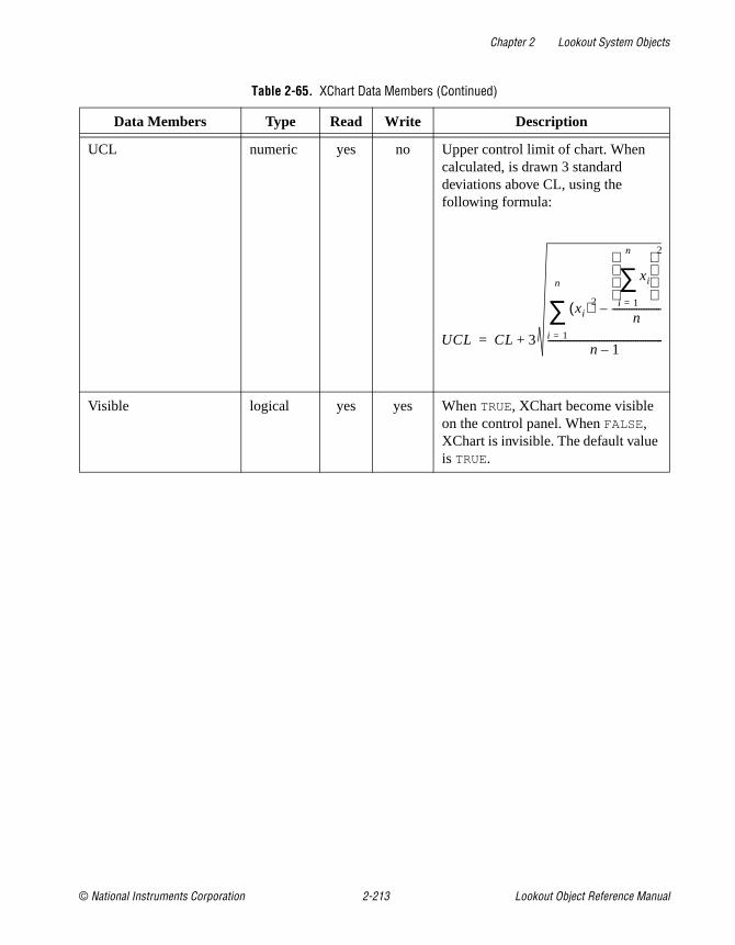
Chapter 2 Lookout System Objects
© National Instruments Corporation 2-213 Lookout Object Reference Manual
UCL numeric yes no Upper control limit of chart. When calculated, is drawn 3 standard deviations above CL, using the following formula:
Visible logical yes yes When TRUE, XChart become visible on the control panel. When FALSE, XChart is invisible. The default value is TRUE.
Table 2-65. XChart Data Members (Continued)
Data Members Type Read Write Description
UCL CL 3
xi( )2
xi
i 1=
n
∑ 2
n--------------------–
i 1=
n
∑n 1–
-----------------------------------------------+=

Chapter 2 Lookout System Objects
Lookout Object Reference Manual 2-214 www.natinst.com
XYChartThe XYChart object class graphically plots X and Y points on a chart in response to a trigger signal.
Figure 2-104. XYChart Definition Parameters Dialog Box
The XYChart object reads the value of the X and Y signals any time Trigger transitions from OFF to ON and plots the corresponding X/Y point on the chart in relation to the chart ranges Min X , Max X, Min Y, and Max Y.
XYChart plots the specified Number of points. When it reaches that limit, it removes the oldest point before plotting the newest one. Number of points must be between 2-4000. All the points on the chart are cleared any time Reset transitions from OFF to ON.

Chapter 2 Lookout System Objects
© National Instruments Corporation 2-215 Lookout Object Reference Manual
You can display X/Y charts in various colors and styles with different vertical and horizontal grid spacing.
Figure 2-105. XYChart Display Parameters Dialog Box
XYChart Data Members
Table 2-66. XYChart Data Members
Data Members Type Read Write Description
ChartXMax numeric yes no Identifies the right most point of the chart graph (the value of the plotted line when it is at 100 percent of the X axis).
ChartXMin numeric yes no Identifies the left most point of the chart graph (the value of the plotted line when it is at zero percent of the X axis).
ChartYMax numeric yes no Identifies the top of the chart graph (the value of the plotted line when it is at 100 percent of the Y axis).

Chapter 2 Lookout System Objects
Lookout Object Reference Manual 2-216 www.natinst.com
ChartYMin numeric yes no Identifies the bottom of the chart graph (the value of the plotted line when it is at zero percent of the Y axis).
Visible logical yes yes When TRUE, X/Y chart become visible on the control panel. When FALSE, it is invisible. The default value is TRUE.
Table 2-66. XYChart Data Members (Continued)
Data Members Type Read Write Description

© National Instruments Corporation 3-1 Lookout Object Reference Manual
3Lookout Driver and Protocol Objects
This chapter describes Lookout Driver and protocol object classes, listed in alphabetical order. Input parameter syntax and data members are documented for each object class, along with a description of the functionality of each object class.

Chapter 3 Lookout Driver and Protocol Objects
Lookout Object Reference Manual 3-2 www.natinst.com
AB_PLC2,AB_PLC5,AB_SLC500
Lookout uses the AB object classes to communicate with the Allen-Bradley family of PLC controllers using a variety of interfaces.
Lookout can communicate with a member of the PLC-2 family in the following ways:
• Through a Data Highway Plus (DH+) connection to an Allen-Bradley 1785-KA3 PLC-2 adapter module using an Allen-Bradley 1784-KT, 1784-KTx, or 1784-PCMK card, or an S-S Technologies 5136-SD direct-link interface card installed in the computer,
• Through the serial port using an Allen-Bradley KF2 module (which converts serial DF1 to DH+) to an Allen-Bradley 1785-KA3 PLC-2 adapter module, or
• Through a direct DF1 serial connection to the PLC programming port.
Lookout can communicate with a member of the PLC-5 family in the following ways:
• Through a direct Ethernet connection to the PLC AUI port,
• Through a direct DH+ connection using a 1784-KT, 1784-KTx, 1784-PCMK, or 5136-SD card installed in the computer,
• Through the serial port via a KF2 module which converts serial DF1 to DH+, or
• Through a direct DF1 serial connection to the PLC programming port.
Lookout can communicate with a member of the SLC-500 family in the following ways:
• Through a direct DH+ connection using a 1784-KT, 1784-KTx, 1784-PCMK, or 5136-SD card installed in the computer,
• Through the serial port via a KF2 module which converts serial DF1 to DH+,
• Through the serial port using an Allen-Bradley 1747-KE card (which plugs into the SLC chassis and converts DF1 to DH 485),
• Through the serial port using a stand-alone Allen-Bradley 1770-KF3 communication interface module which converts DF1 to DH 485,

Chapter 3 Lookout Driver and Protocol Objects
© National Instruments Corporation 3-3 Lookout Object Reference Manual
• Through a direct DF1 serial connection to a SLC 5/03 or SLC 5/04 programming port, or
• Through a direct DH485 connection using a 1784-PCMK card in conjunction with either a 1747-AIC or 1761-NET-AIC module.
Figure 3-1. Allen-Bradley Parameter Dialog Box
PLC Address refers to the PLC network node address setting as configured on the physical device. If devices share a common Interface, they require unique addresses. When using DF1 protocol (serial communications), valid addresses range from 0 to 254 decimal. When using DH+, valid addresses range from 0 to 77 octal.
PLC Model specifies the particular type of PLC or SLC you are representing with this object. The PLC Model you select determines what native data members comprise the object.
PollRate is a numeric expression that determines how often to poll the device. Lookout polls the device at the specified time interval. Normally, this is a simple time constant such as 0:01 (one second). See Numeric Data Members in Chapter 2, How Lookout Works, of the Getting Started with Lookout manual for information on entering time constants.
Poll is a logical expression. When this expression changes from false to true, Lookout polls the device. You can use a simple expression like the signal from a pushbutton, or a complex algorithm.

Chapter 3 Lookout Driver and Protocol Objects
Lookout Object Reference Manual 3-4 www.natinst.com
Communication alarm priority determines the priority level of the alarms generated by the AB object.
Retry attempts specifies the consecutive number of times Lookout attempts to establish communications with a device if it is not getting a valid response. After it tries the number of Retry attempts specified, the object generates an alarm and begins to Skip every n poll requests after comm failure. Once Lookout reestablishes communications, it polls the device on its regular cycle, as defined by PollRate.
Receive timeout is the time delay Lookout waits for a response from a device before retrying the poll request.
Interface identifies the type of communication hardware you are using. The selection you make here determines what protocol parameters you have to specify. The paragraphs that follow describe interface-specific protocol parameters.
Allen-Bradley Serial Port Interface ParametersThe KE/KF/Serial Interface selection enables serial port communication via a KE card, a KF3 module or KF2 module. When using your serial port, Lookout employs the Allen-Bradley full-duplex (peer-to-peer) DF1 protocol. Figure 3-1 shows an Allen Bradley object configured for serial communications.
Serial port specifies which RS-232C port the object uses for communication to the physical device.
Data rate, Parity, and Error detection reference the settings on the hardware device. The AB object classes support both BCC (block check character) and CRC (cyclic redundancy check) error detection. BCC provides a medium level of data security. CRC ensures a higher level of data security. Choose the settings as configured on your PLC or SLC.
Phone number specifies the number to be dialed if the serial port setting is configured for dial-up. This number only applies to the individual object.

Chapter 3 Lookout Driver and Protocol Objects
© National Instruments Corporation 3-5 Lookout Object Reference Manual
Allen-Bradley DH+ Interface Parameters
Note When you configure an AB_PLC2, AB_PLC5, or AB_SLC500 for DH+, Lookout creates a file called ALLBRAD.INI . This file contains the configuration settings that you enter for your KT card(s). If you plan to run the process file on a Lookout Runtime System, be sure to copy the INI file along with your process (.lkp ) file to the target computer.
The 1784-KT , 1784-KTx , 1784-PCMK, and S-S 5136-SD Interface selections enable direct connection of your computer to a DH+ network. The following illustration shows an AB_SLC500 configured for DH+ communications using a 1784-KTx card.
Figure 3-2. AB_SLC-500 Definition Parameters Dialog Box Configured for DH+ Communications
Card number selects which network interface card that the PLC is connected to in case your computer has multiple KT or S-S cards.
Card DH+ node address identifies the address of the interface card in the DH+ network. Valid addresses range from 0 to 77 octal. The node address of the card must be unique—that is, it must not be the same as the address of any other device on the DH+ network.

Chapter 3 Lookout Driver and Protocol Objects
Lookout Object Reference Manual 3-6 www.natinst.com
Memory address specifies the base address location of the selected interface card memory. Your selection should match the settings on the card. If you are using multiple interface cards, be sure each card has a unique address. The network interface cards use dual-ported memory. For this reason, if you are using a memory manager such as EMM386 it is important to add a memory exclusion statement to your CONFIG.SYS file. The table on the following page lists base memory address selections and corresponding exclusions for all legal memory addresses for the 1784-KT card.
Use Max node address to maximize the performance of a DH485 network by assigning addresses to nodes on the network using consecutive numbers starting with zero. Set the Max node address to the maximum of the assigned node addresses. By default, the value of this variable is 31, which is the largest legal address for any node on a DH485 network.
The 1784-KT interface card has on-board network termination resistors. If you are using such a card and if your computer is the last node on the network and if the cable does not already have a terminating resistor on it, then select the Enable link termination resistor check box.
Use the Card exists in this computer check box to instruct Lookout whether or not to look for the interface card in the computer. Be sure to check this box when you are ready to start polling your PLCs. When you check this box and select OK , Lookout initializes the card, activates its self-test, and downloads its driver firmware. Then polling begins. Leave the Card exists in this computer check box deselected (this is the default setting) if the card is not in your computer (for example, if you are developing a process on a computer different from the one that will be running the process) or if you do not want to poll any PLC connected to the card.
If you deselect the Card exists in this computer check box, you are disabling communications using this interface card with all PLCs connected to it.

Chapter 3 Lookout Driver and Protocol Objects
© National Instruments Corporation 3-7 Lookout Object Reference Manual
Baud rate (1784-KTx, 1784-PCMK, 5136-SD only) selects the baud rate of the DH+ network. The default is 57.6k baud. Before selecting a higher baud rate, be aware of that only a few PLCs (such as the SLC5/04) support higher baud rates; that every node on a DH+ network must support the baud rate used on that network; that the maximum network cable length is smaller for higher baud rates; and that the correct values for the termination resistors at the ends of the network cable are different for higher baud rates. Consult the manuals that came with your hardware for more detailed information.
Table 3-1. Allen-Bradley DH+ Interface Memory Addresses
Memory Address
AB 1784-KTExclude
AB 1784-KTx1784-PCMK
ExcludeSS-5136-SD
Exclude* Recommendation
A000 A300-A3FF A000-A0FF A000-A3FF Typically used by VGA drivers. Use if no other option is available.A400 A700-A7FF A400-A4FF A400-A7FF
A800 AB00-ABFF A800-A8FF A800-ABFF
AC00 AF00-AFFF AC00-ACFF AC00-AFFF
B000 B300-B3FF B000-B0FF B000-B3FF Used by MDA & CGA drivers. Use if no Dxxx option is available.B400 B700-B7FF B400-B4FF B400-B7FF
B800 BB00-BBFF B800-B8FF B800-BBFF
BC00 BF00-BFFF BC00-BCFF BC00-BFFF
C000 C300-C3FF C000-C0FF C000-C3FF Typically used by BIOS. Use if no Dxxx option is available.C400 C700-C7FF C400-C4FF C400-C7FF
C800 CB00-CBFF C800-C8FF C800-CBFF
CC00 CF00-CFFF CC00-CCFF CC00-CFFF
D000 D300-D3FF D000-D0FF D000-D3FF Normally available.Try to use one of these first.
D400 D700-D7FF D400-D4FF D400-D7FF
D800 DB00-DBFF D800-D8FF D800-DBFF
DC00 DF00-DFFF DC00-DCFF DC00-DFFF
* The 5136-SD memory exclusions recommended here are based on 16K memory mapping. Because you are using the SS card to emulate the KT card, there is no advantage to using its 32K memory access capability.

Chapter 3 Lookout Driver and Protocol Objects
Lookout Object Reference Manual 3-8 www.natinst.com
IRQ (all cards) identifies the interrupt setting of all DH+ interface cards installed in the computer. This selection should match the IRQ settings on all of the interface cards.
Assigning an interrupt to the interface card(s) improves overall computer performance somewhat. Any time one of the cards receives an input, it generates an interrupt recognized by Lookout.
Caution Be sure to verify that no other drivers or cards are mapped to the selected memory address or use the same interrupt.
Allen-Bradley Ethernet Interface ParametersThe Ethernet Interface selection enables direct communication between your computer and a PLC using a standard Ethernet network. The following diagram shows an AB_PLC5 configured for Ethernet communications.
Figure 3-3. AB_PLC5 Definition Parameters Dialog Box Configured for Ethernet Communications
IP address specifies the Internet protocol address of the PLC. An Internet protocol address consists of four numbers, separated by periods. Each number ranges from zero to 255 decimal. Thus, a typical Internet address might be 128.7.9.231. Ensure that the IP address you enter matches the

Chapter 3 Lookout Driver and Protocol Objects
© National Instruments Corporation 3-9 Lookout Object Reference Manual
Internet protocol address of the PLC your object represents. You can also enter the IP address by name.
Using the 5136-SD card from S-S Technologies, Inc.To use the 5136-SD card, select the S-S 5136-SD interface in the Create Object dialog box. It is not necessary to run the sdinst.exe program that ships with the card because Lookout downloads the KT-emulation module automatically as part of the initialization process. It is, however, necessary to tell Lookout the port address specified by the switch settings on the card.
Figure 3-4. AB_PLC5 Definition Parameters Dialog Box Configured for the 5136-SD card

Chapter 3 Lookout Driver and Protocol Objects
Lookout Object Reference Manual 3-10 www.natinst.com
Allen-Bradley Register AddressingLookout has adopted a sequential, flat addressing scheme for the Allen-Bradley PLCs. The addresses are sequential by data type, having nothing to do with the actual slot number. For example, consider the following slot configuration:
You can see from the example, the slot number of the module is irrelevant to Lookout, and the input channels follow consecutive numbers as the output channels follow their own consecutive numbers. Input and Output word addresses are 1 based; all other words are 0 based.
Allen-Bradley Data MembersEach AB object contains a great deal of data. All readable and writable members (inputs/outputs) are bundled with the object. As soon as you create an AB object you immediately have access to all the object data members.
The AB object classes automatically generate an efficient read/write blocking scheme based on the inputs and outputs you are using in your process file. You are not required to build your own I/O blocking table. However, you can ensure peak performance by organizing your PLC data into contiguous groups.
PLC slot Location Type of Module in PLC Slot Channel Address in Lookout
slot 1 16 channel analog input I:1-I:16
slot 2 16 channel analog output O:1-O:16
slot 3 8 channel input, 8 channel output I:17-I:24, O:17-O:24
slot 4 16 channel analog input I:25-I:32
Table 3-2. AB_PLC2 Data Members
Data Member Type Read Write Description
0 - 7777 numeric yes yes 16-bit signed binary word ranging from –32,768 to +32,767
0_0 - 7777_17 logical yes no One bit within a 16-bit binary word
CommFail logical yes no Object-generated signal that is ON if, for any reason, Lookout cannot communicate with the PLC.

Chapter 3 Lookout Driver and Protocol Objects
© National Instruments Corporation 3-11 Lookout Object Reference Manual
OffHook logical no yes When true, instructs the PLC to retain exclusive use of its assigned communication port. This prevents Lookout from hanging up between polls, saving the redial overhead. This also prevents other blocks from communicating over the same channel.
Poll logical no yes When transitioned from false to true, the Lookout object polls the PLC device
PollRate numeric no yes Specifies the frequency at which the Lookout object polls the PLC device
Update logical yes no Object-generated signal that pulses each time the object polls the device
Table 3-3. AB_SLC500 Data Members
Data Member Type Read Write Description
B:0 - B255:255 numeric yes yes 16-bit signed binary word ranging from –32,768 to +32,767
B:0_0-B255:255_15 logical yes yes One bit within a 16-bit binary word
B_0 - B255_4095 logical yes yes One bit within the specified datafile. For example, B3_32 specifies datafile 3, word 2, bit 1.
C:0.ACC - C255:255.ACC
numeric yes yes Counter accumulated value. Two-byte signed word ranging from –32,768 to +32,767
C:0.PRE - C255:255.PRE
numeric yes yes Preset counter value. Two-byte signed word ranging from –32,768 to +32,767
C:0_CU - C255:255_CU logical yes yes Counter up-enable bit.
C:0_DN - C:255:255_DN
logical yes yes Counter done bit.
Table 3-2. AB_PLC2 Data Members (Continued)
Data Member Type Read Write Description

Chapter 3 Lookout Driver and Protocol Objects
Lookout Object Reference Manual 3-12 www.natinst.com
C:0_OV - C255:255_OV
logical yes yes Counter overflow bit.
C:0_UA - C255:255_UA
logical yes yes Counter update accumulation bit (HSC in fixed controller only)
C:0_UN - C255:255_UN
logical yes yes Counter underflow bit.
C:0_CD -C255:255_CD logical yes yes Counter down-enable bit.
CommFail logical yes no Object-generated signal that is ON if, for any reason, Lookout cannot communicate with the SLC.
F:0-F255:255 numeric yes yes Floating point value
I:0 - I:30 numeric yes yes Unsigned 16-bit input value ranging from 0 to 65,535
I:0_0 - I:30_15 logical yes yes One bit within a 16-bit input word
N:0 - N255:255 numeric yes yes 16-bit signed integer value ranging from –32,768 to +32,767.
N:0_0 - N255:255_15 logical yes yes One bit within a 16-bit signed integer word
O:0 - O:30 numeric yes yes Unsigned 16-bit output value ranging from 0 to 65,535
O:0_0 - O:30_15 logical yes yes One bit within a 16-bit output word
OffHook logical no yes When true, instructs the PLC to retain exclusive use of its assigned communication port. This prevents Lookout from hanging up between polls, saving the redial overhead. This also prevents other blocks from communicating over the same channel.
Poll logical no yes When transitioned from false to true, the Lookout object polls the SLC device
Table 3-3. AB_SLC500 Data Members (Continued)
Data Member Type Read Write Description

Chapter 3 Lookout Driver and Protocol Objects
© National Instruments Corporation 3-13 Lookout Object Reference Manual
PollRate numeric no yes Specifies the frequency at which the Lookout object polls the SLC device
R:0_FD - R255:255_FD logical yes yes Control “found” single-bit logical indicator
R:0.LEN - R255:255.LEN
numeric yes yes Control “length” signed integer ranging from –32,768 to +32,767
R:0.POS - R255:255.POS
numeric yes yes Control “position” signed integer ranging from –32,768 to +32,767
R:0_DN - R255:255_DN
logical yes yes Control “done” single-bit logical indicator
R:0_EM - R255:255_EM
logical yes yes Control “empty” single-bit logical indicator
R:0_EN -R255:255_EN logical yes yes Control “enable” single-bit logical indicator
R:0_ER - R255:255.ER logical yes yes Control “error” single-bit logical indicator
R:0_EU - R255:255_EU logical yes yes Control “enable unloading” single-bit
R:0_IN - R255:255.IN logical yes yes Control “inhibit comparison” flag single-bit logical indicator
R:0_UL - R255:255_UL logical yes yes Control “unload” single-bit logical indicator
S:0 - S:96 numeric yes yes SLC status file containing a signed integer ranging from –32,768 to +32,767 (see Allen-Bradley documentation)
S:0_0 -S:96_15 logical yes yes Individual SLC status bits (see Allen-Bradley documentation)
ST9:0 - ST255:255 text yes yes String, limited to 83 characters in length. See the note on Allen-Bradley string data members at the end of this table.
Table 3-3. AB_SLC500 Data Members (Continued)
Data Member Type Read Write Description

Chapter 3 Lookout Driver and Protocol Objects
Lookout Object Reference Manual 3-14 www.natinst.com
Note There is no Allen-Bradley default file type associated with strings. You must configure your Allen-Bradley device to have a string file. See your Allen-Bradley documentation for details on this configuration procedure.
The string data member only works with the SLC 500 Enhanced series of PLCs, including the SLC 5/03; OS301 and SLC 5/04., and with the PLC 5 Enhanced series, PLC 5/11, PLC 5/20, PLC 5/30, PLC 5/40, PLC 5/60, PLC 5/80.
T:0.ACC - T255:255.ACC
numeric yes yes Accumulated timer value ranging from –32,768 to +32,767
T:0.PRE - T255:255.PRE
numeric yes yes Preset timer value ranging from –32,768 to +32,767
T:0_DN - T255:255_DN logical yes yes Timer “done” single-bit logical indicator
T:0_EN - T255:255_EN logical yes yes Timer “enabled” single-bit logical indicator
T:0_TT - T255:255_TT logical yes yes Timer “timing” single-bit logical indicator
Update logical yes no Object-generated signal that pulses each time the object polls the device
Table 3-4. AB_PLC5 Data Members
Data Member Type Read Write Description
B:0 - B999:999 numeric yes yes 16-bit signed binary word ranging from –32,768 to +32,767
B:0_0-B999:999_15 logical yes yes One bit within a 16-bit binary word.
B_0 - For B999_15999 logical yes yes One bit within the specified datafile; for example, B3_32 specifies datafile 3, word 2, bit 1.
C:0.ACC - C999:999.ACC
numeric yes yes Counter accumulated value. Two-byte signed word ranging from –32,768 to +32,767
Table 3-3. AB_SLC500 Data Members (Continued)
Data Member Type Read Write Description

Chapter 3 Lookout Driver and Protocol Objects
© National Instruments Corporation 3-15 Lookout Object Reference Manual
C:0.PRE - C999:999.PRE
numeric yes yes Preset counter value ranging from –32,768 to +32,767.
C:0_CD - C999:999_CD logical yes yes Counter down-enable bit.
C:0_CU - C999:999_CU logical yes yes Counter up-enable bit.
C:0_DN - C:999:999_DN
logical yes yes Counter done bit.
C:0_OV - C999:999_OV
logical yes yes Counter overflow bit.
C:0_UA - C999:999_UA
logical yes yes Counter update accumulation bit (HSC in fixed controller only).
C:0_UN - C999:999_UN
logical yes yes Counter underflow bit.
CommFail logical yes no Object-generated signal that is ON if, for whatever reason, Lookout cannot communicate with the PLC.
F:0-F999:999 numeric yes yes Floating point value.
I:0 - I:277 numeric yes yes Unsigned 16-bit input value ranging from 0 to 65,535.
I:0_0 - I:277_17 logical yes yes One bit within a 16-bit input word (octal).
N:0 - N999:999 numeric yes yes 16-bit signed integer value ranging from –32,768 to +32,767.
N:0_0 - N999:999_15 logical yes yes One bit within a 16-bit signed integer word.
O:0 - O:277 numeric yes yes Unsigned 16-bit output value ranging from0 to 65,535.
O:0_0 - O:277_17 logical yes yes One bit within a 16-bit output word (octal).
Table 3-4. AB_PLC5 Data Members (Continued)
Data Member Type Read Write Description

Chapter 3 Lookout Driver and Protocol Objects
Lookout Object Reference Manual 3-16 www.natinst.com
OffHook logical no yes When true, instructs the PLC to retain exclusive use of its assigned communication port. This prevents Lookout from hanging up between polls, saving the redial overhead. This also prevents other blocks from communicating over the same channel.
Poll logical no yes When transitioned from false to true, the Lookout object polls the PLC device.
PollRate numeric no yes Specifies the frequency at which the Lookout object polls the PLC device.
R:0.LEN - R999:999.LEN
numeric yes yes Control “length” signed integer ranging from –32,768 to +32,767.
R:0.POS - R999:999.POS
numeric yes yes Control “position” signed integer ranging from –32,768 to +32,767.
R:0_DN - R999:999_DN
logical yes yes Control “done” single-bit logical indicator.
R:0_EM - R999:999_EM
logical yes yes Control “empty” single-bit logical indicator.
R:0_EN - R999:999_EN logical yes yes Control “enable” single-bit logical indicator.
R:0_ER - R999:999.ER logical yes yes Control “error” single-bit logical indicator.
R:0_EU - R999:999_EU logical yes yes Control “enable unloading” single-bit logical indicator.
R:0_FD - R999:999_FD logical yes yes Control “found” single-bit logical indicator.
R:0_IN - R999:999.IN logical yes yes Control “inhibit comparison” flag logical indicator.
R:0_UL - R999:999_UL logical yes yes Control “unload” single-bit logical indicator.
Table 3-4. AB_PLC5 Data Members (Continued)
Data Member Type Read Write Description

Chapter 3 Lookout Driver and Protocol Objects
© National Instruments Corporation 3-17 Lookout Object Reference Manual
S:0 - S:127 numeric yes yes PLC status file containing a signed integer ranging from –32,768 to +32,767 (see Allen-Bradley documentation).
S:0_0 - S:127_15 logical yes yes Individual PLC status bits (see Allen-Bradley documentation).
ST9:0 - ST255:255 text yes yes String, limited to 83 characters in length. See the note on Allen-Bradley string data members at the end of this table.
T:0.ACC - T999:999.ACC
numeric yes yes Accumulated timer value ranging from –32,768 to +32,767.
T:0.PRE - T999:999.PRE
numeric yes yes Preset timer value ranging from –32,768 to +32,767.
T:0_DN - T999:999_DN logical yes yes Timer “done” single-bit logical indicator.
T:0_EN - T999:999_EN logical yes yes Timer “enabled” single-bit logical indicator.
T:0_TT - T999:999_TT logical yes yes Timer “timing” single-bit logical indicator.
Update logical yes no Object-generated signal that pulses each time the object polls the PLC device.
Table 3-4. AB_PLC5 Data Members (Continued)
Data Member Type Read Write Description

Chapter 3 Lookout Driver and Protocol Objects
Lookout Object Reference Manual 3-18 www.natinst.com
Note There is no Allen-Bradley default file type associated with strings. You must configure your Allen-Bradley device to have a string file. See your Allen-Bradley documentation for details on this configuration procedure.
The string data member only works with the SLC 500 Enhanced series of PLCs, including the SLC 5/03; OS301 and SLC 5/04., and with the PLC 5 Enhanced series, PLC 5/11, PLC 5/20, PLC 5/30, PLC 5/40, PLC 5/60, PLC 5/80.
Allen-Bradley Error MessagesAB objects report the statuses of commands they issue to AB devices. When Lookout receives a response from an AB device, it reads the status (STS) byte and, if necessary, the extended status (EXT STS) byte to verify the device executed the Lookout command properly. If the command was not executed properly, Lookout reports the failure as an alarm containing the status code and its meaning. The following is an example of such an alarm:
EXT STS = 0F: not enough levels in address
AB object classes can also generate alarms internally. The following is a list of AB alarms generated by Lookout, their descriptions, and possible responses. In the messages, KT is used to refer to any of the DH+ interface cards (1784-KT, 1784-KTx, 1784-PCMK, or 5136-SD) and SS is used to refer to the 5136-SD card.
Cannot resolve ip address: address
The AB object failed to find any node on the network that corresponds to the given IP address. Confirm that the IP address entered in the Modify Object dialog box is correct.
Cannot get session id from plc
The AB object sent a message to the PLC requesting a TCP/IP session and failed to receive a satisfactory response.
Cannot communicate with device (code=dd)
The AB object timed out while waiting for a response (via TCP/IP) from the PLC. If the code is 0, the object timed out while trying to establish the TCP/IP connection; if the code is 1, the object timed out while waiting for a session id from the PLC; if the code is 2, the object timed out while waiting for a response to a poll request. Confirm that the IP address of the PLC has been entered correctly and that the PLC is reachable over the TCP/IP network.
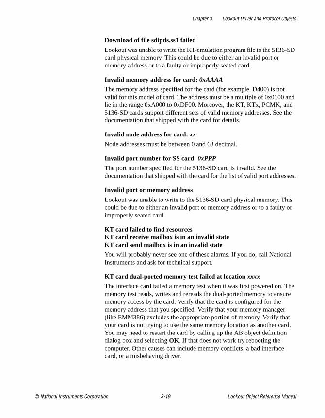
Chapter 3 Lookout Driver and Protocol Objects
© National Instruments Corporation 3-19 Lookout Object Reference Manual
Download of file sdipds.ss1 failed
Lookout was unable to write the KT-emulation program file to the 5136-SD card physical memory. This could be due to either an invalid port or memory address or to a faulty or improperly seated card.
Invalid memory address for card: 0xAAAA
The memory address specified for the card (for example, D400) is not valid for this model of card. The address must be a multiple of 0x0100 and lie in the range 0xA000 to 0xDF00. Moreover, the KT, KTx, PCMK, and 5136-SD cards support different sets of valid memory addresses. See the documentation that shipped with the card for details.
Invalid node address for card: xx
Node addresses must be between 0 and 63 decimal.
Invalid port number for SS card: 0xPPP
The port number specified for the 5136-SD card is invalid. See the documentation that shipped with the card for the list of valid port addresses.
Invalid port or memory address
Lookout was unable to write to the 5136-SD card physical memory. This could be due to either an invalid port or memory address or to a faulty or improperly seated card.
KT card failed to find resourcesKT card receive mailbox is in an invalid stateKT card send mailbox is in an invalid state
You will probably never see one of these alarms. If you do, call National Instruments and ask for technical support.
KT card dual-ported memory test failed at location xxxx
The interface card failed a memory test when it was first powered on. The memory test reads, writes and rereads the dual-ported memory to ensure memory access by the card. Verify that the card is configured for the memory address that you specified. Verify that your memory manager (like EMM386) excludes the appropriate portion of memory. Verify that your card is not trying to use the same memory location as another card. You may need to restart the card by calling up the AB object definition dialog box and selecting OK . If that does not work try rebooting the computer. Other causes can include memory conflicts, a bad interface card, or a misbehaving driver.

Chapter 3 Lookout Driver and Protocol Objects
Lookout Object Reference Manual 3-20 www.natinst.com
KT card CTC test timed outKT card CTC test failed with status code xx
The interface card failed the Counter Timer Circuit test when it was first powered on. This test verifies proper functionality of the card timer and counter modes over all CTC channels. You may need to restart, reseat, or replace the interface card.
KT card timed out while loading protocol codeKT card failed with status code xx while loading protocol
Lookout was not able to transfer a loader file to the card and subsequently download the card protocol firmware. Try to restart the interface card by calling up the AB object definition dialog box and selecting OK . If that does not work try rebooting the computer.
KT card is no longer responding
The Lookout AB object did not receive the interface card heartbeat within the last second. Normally, the card generates a heartbeat any time it receives the DH+ network token. If the alarm does not deactivate after 30 seconds, try to restart the card by calling up the AB object definition dialog box and selecting OK . If that does not work try restarting Lookout or rebooting the computer.
KT card memory address conflicts with card n
Lookout found another interface card with the same memory address. Be sure that the memory address on each interface card is different and that the corresponding Memory address in the Lookout object matches the card address.
KT card not present in this computer
The Card exists in this computer check box is deselected (this is the default setting). Select Object»Modify to retrieve the PLC definition parameters dialog box and select the Card exists in this computer check box and OK to initialize the card.
KT card RAM test timed outKT card RAM test failed with status code xx
The interface card failed a memory test when it was first powered on. The memory test writes a pattern to on-board RAM and reads its content to verify the card memory is working. Confirm that the memory address specified in the Object»Modify dialog box is correct. You may need to restart, reseat, or replace the card.

Chapter 3 Lookout Driver and Protocol Objects
© National Instruments Corporation 3-21 Lookout Object Reference Manual
KT card signature test failed
The AB object does not recognize the card. Make sure that the interface card is actually installed in the PC and that you indicated the correct memory address in Lookout. You may need to reseat the card, or the card may require repair. Also ensure that you did not identify more Card Numbers than actual physical cards.
KT card SI0 test timed outKT card SI0 test failed with status code xx
The interface card failed the Serial Input Output test when it was first powered on. You may need to restart, reseat, or replace the interface card.
KT card send mailbox timed out
The AB object timed out while waiting for the KT card to signal that it is ready to be given a new message to send. This is most likely due to a communication problem between the computer and the PLC. Confirm that the network cable is properly installed and that the PLC is turned on.
NAK response received
The AB object received a NAK (not acknowledged) response when it polled the device. The device received a command from Lookout but it did not accept the message. The command that the device received may be incomplete or contain irregularities due to poor network performance. If your Serial Port is configured for radio, you may need to adjust the RTS delay off setting. Also consider increasing the number of Retry attempts.
No response — no ACK for our transmission
Lookout is not getting any response from the device. This could be caused by just about anything. Verify that the Data rate, Parity, and Error detection settings are the same as the settings on the device. Make sure you are using the proper Serial port on your computer. Verify that the device interface module and other network equipment is connected and working properly. If you are using a modem, verify that your object Phone number and the serial port Dial-up settings are correct. This may also be caused by low level noise or reflections on the highway, or marginal circuitry on a card.

Chapter 3 Lookout Driver and Protocol Objects
Lookout Object Reference Manual 3-22 www.natinst.com
No response within timeout period No response received after receiving ENQ
The AB object received an acknowledgment of its poll from the device. The device accepted the command from Lookout. However, the device did not appear to send anything else back in response. You may have to increase Receive timeout to make sure Lookout allows enough time to receive the message.
EOT response received
The AB object received an EOT (end of transmission) response when it polled the device indicating that the device did not have a message ready to give in response to the Lookout poll request. It is unlikely that you will ever see this error message.
Received TSN does not matchResponse message garbled -- bad CRC or bad BCCResponse message garbled -- no DLE EXTResponse message garbled -- bad DLE follower
The AB object is receiving messages from the device. However, the messages may be failing the selected data integrity test. Verify that the object Error detection setting is the same as the settings on the device. Another cause may be that the last part of the message is actually getting clipped off before it is completed. You may have to increase the Receive gap Serial Port setting to ensure Lookout is receiving the entire message. If your Serial Port is configured for radio this could be caused by an audible squelch tail occurring at the end of a radio transmission. You may need to adjust the RTS delay off or the CTS timeout settings. Also consider increasing the number of Retry attempts.
Socket communications error dd: msg
The AB object has encountered a problem while attempting to communicate using TCP/IP. The error number dd and corresponding error message msg give further information. Confirm that the IP address of the PLC has been entered correctly and that the PLC is reachable over the TCP/IP network.
SS card failed
This message is suffixed with an error message read from the card itself. You may need to contact the vendor of your card for technical support.
Chapter 3 Lookout Driver and Protocol Objects
© National Instruments Corporation 3-23 Lookout Object Reference Manual
SS card failed while performing diagnostics
Lookout successfully wrote the KT-emulation program to the 5136-SD card, but the program failed to terminate. Try running the sdinst.exe program that ships with the 5136-SD card, using the CHK option to confirm that the card is working properly.
Unable to access physical memory at segment 0xAAAA
Lookout was unable to access the memory at the given segment address. The memory may already be in use by the operating system or by another application. Either change the object memory address (which may involve changing switch settings on the card itself) or, if you are using a memory manager, make sure that it is excluding the correct portion of memory.
Unable to open port 0xPPP for SS card
Lookout was unable to open the port number specified for the 5136-SD card. Make sure that you have specified the port that is selected by the jumper settings on the card. Make sure that port and the following two ports (for example, 250, 251, and 252) are not in use by any other devices in your computer.
Unexpected data response length Unexpected responseUnhandled error
You will probably never see one of these alarms. If you do, call National Instruments and ask for technical support.

Chapter 3 Lookout Driver and Protocol Objects
Lookout Object Reference Manual 3-24 www.natinst.com
AdvantechPCLThe AdvantechPCL object class enables Lookout to communicate with the Advantech PC-MultiLab Card, model PCL-711B. The MultiLab Card installs in your computer and provides one analog output, eight analog inputs, 16 digital inputs and 16 digital outputs.
Figure 3-5. AdvantechPCL Definition Parameters Dialog Box
Card I/O port address indicates the base I/O port address you chose using DIP switch settings on the card. The Advantech card uses 16 consecutive I/O port address locations in your computer. So if you identify base address 220 (hex), it uses addresses 220 to 22F. Valid base addresses range from 000 to 3F0. If your computer does not have an Advantech card installed, be sure to select no card .
Note I/O ports identify to the CPU the location of basic system components such as serial ports, video cards, and disk controllers. Check your computer hardware manual and add-on board configurations to be sure you are assigning a unique I/O port address to the Advantech card.
Scanning interval is a numeric parameter that determines how often Lookout scans the card for changed values. Valid intervals range from 10 to 1000 milliseconds.
AI gain specifies the input amplification gains of all analog input signals (AI0 – AI7). For the highest possible resolution, you should amplify the input signals so that their maximum voltage swing equals their maximum input range. The following table lists recommended settings.
If your maximum voltage range is… use A1 gain…
±5V 1
±2.5V 2X

Chapter 3 Lookout Driver and Protocol Objects
© National Instruments Corporation 3-25 Lookout Object Reference Manual
Communication alarm priority determines the priority level of the alarms generated by the AdvantechPCL object class.
AdvantechPCL Data MembersThe table that follows lists data members supported by the AdvantechPCL object class.
±1.25V 4X
±0.625V 8X
±0.3125V 16X
Table 3-5. AdvantechPCL Data Members
Data Member Type Read Write Description
AI0 – AI7 Analog yes no Analog input where AI0 represents A/D 0 (pin 1 on CN1) and AI7 represents A/D 7 (pin 15 on CN1). Each input is a 12-bit integer, ranging from 0 to 4095.
AO0 Analog no yes Analog output where AO0 represents D/A (pin 17 on CN1). This output is a 12-bit integer, ranging from 0 – 4095 (+5V or +10V, depending on jumper JP1).
CommFail logical yes no Object-generated signal that is on if, for whatever reason, Lookout cannot communicate with the card.
DI0 – DI15 logical yes no Digital input where DI0 represents pin 1 and DI15 represents pin 16 on CN4. Returns False when a monitored signal is open (>2.0V), True when the signal is shorted (<0.8V).
DO0 – DO15 logical no yes Digital output where DO0 represents pin 1 and DO15 represents pin 16 on CN3.
Update logical yes no Object-generated signal that pulses each time the object scans the device.
If your maximum voltage range is… use A1 gain…

Chapter 3 Lookout Driver and Protocol Objects
Lookout Object Reference Manual 3-26 www.natinst.com
ApplicomApplicom is a set of object classes Lookout uses to communicate with a series of devices and protocols, including the Applicom on-board database (Local mode), April 1000, Klockner-Moeller, Otic Fischer & Porter, Profibus DP, Profibus FMS, Profibus L2, SAIA-SBus, Siemens S7MPI, Siemens H1, Siemens S5 AS511, and Telemecanique.
The following illustration on the left is the dialog box for creating an Applicom Local object. At right is the dialog box for creating an Applicom Telemecanique object. The Telemecanique object has the same parameters as all the other Applicom objects except for Applicom Local, and makes a good representative sample for the group.
Figure 3-6. Applicom Definition Parameters Dialog Boxes
Board ID identifies the board you are trying to address.
Address of status word is the address of the specific cyclic function of your Applicom board that you want to interact with using this Applicom Local object.
Channel ID identifies the Applicom channel your device is communicating on.
Equipment ID is the Applicom equipment ID for the device you are connecting to.
Scanning interval is the time period between polls. Valid range is 10 - 65535 (expressed in msec).

Chapter 3 Lookout Driver and Protocol Objects
© National Instruments Corporation 3-27 Lookout Object Reference Manual
Communication alarm priority determines the priority level of the alarms generated by the object.
Retry attempts before failure specifies the consecutive number of times Lookout attempts to establish communications with a device if it is not getting a valid response. After it tries the number of Retry attempts specified, the Applicom object generates an alarm and releases the communication port back to the communications service which then moves on to the next device in the polling queue (if any). Refer to Chapter 3, Serial Communications, in the Lookout Developer’s Manual for more detailed information.
Table 3-6. Lookout Applicom Object Classes and the Corresponding Protocols/Devices
Object Class Device/protocol
Applicom Local Any device or protocol supported by Applicom cards. See the Special Instructions on Using the Applicom Local Object Class section, for more detailed information on using this object.
Applicom JBUS Devices using Jbus protocol (mostly those made by April).
April 1000 April 1000 PLC using Ethway or Fipway protocols.
Klockner-Moeller Klockner-Moeller SUCOS PS32 and PS316 PLC using the Sucoma link.
Otic Fischer & Porter Otic Fischer & Porter controllers of series 2000, 5000, and 2000 supervisor using the DATALINK protocol.
Profibus DP Profibus DP with any I/O module or PLC that communicates on a Profibus network using the Decentralized Periphery protocol (includes some Siemens S5 PLCs).
Profibus FMS Profibus FMS protocol with any master or slave FMS device on a Profibus network (includes most Siemens PLCs).
Profibus L2 Profibus L2 protocol with Siemens S5 PLC using Siemens France messaging system. (The PLC must be running a program also distributed with the Applicom hardware.)
SAIA-SBus SAIA SBus master protocol.
Siemens S7MPI Siemens MPI protocol with Siemens S7 PLCs.
Siemens H1 Sinec H1 protocol with various Siemens PLCs.

Chapter 3 Lookout Driver and Protocol Objects
Lookout Object Reference Manual 3-28 www.natinst.com
Applicom Data Members
Siemens S5 AS511 AS511 (programming port) protocol with Siemens S5 PLCs.
Telemecanique Uni-Telway, Ethway and Fipway protocols with all Telemecanique PLCs.
Table 3-7. Applicom Local Data Members
Data Member Type Read Write Description
B0-B31999 logical yes yes Output bits
CommFail logical yes no Object-generated signal that is ON if Lookout cannot communicate with the device(s)
D0-D31998 numeric yes yes Internal double words
DS0-DS31998 numeric yes yes Signed internal double words
F0-F31998 numeric yes yes Internal floating words
O0-O13999 numeric yes yes Internal bytes
OS0-OS13999 numeric yes yes Signed internal bytes
Update logical yes no Goes FALSE when a poll starts and TRUE when a poll completes
W0-W31999 numeric yes yes Output words
WS0-WS31999 numeric yes yes Signed output words
Table 3-8. Applicom JBUS Data Members
Data Member Type Read Write Description
B0-B4294967295 logical yes yes Internal bits
BI0-BI4294967295 logical yes no Input bits
BO0-BO4294967295 logical yes yes Output bits
Table 3-6. Lookout Applicom Object Classes and the Corresponding Protocols/Devices (Continued)
Object Class Device/protocol

Chapter 3 Lookout Driver and Protocol Objects
© National Instruments Corporation 3-29 Lookout Object Reference Manual
CommFail logical yes no Object-generated signal that is ON if Lookout cannot communicate with the device(s)
D0-D4294967295 numeric yes yes Internal double words
F0-F4294967295 numeric yes yes Internal floating words
O0-O4294967295 numeric yes yes Internal bytes
O0.0-O4294967295.7 logical yes yes Bit in internal bytes
O0.0-O4294967295.7 logical yes yes Bit in internal bytes
OI0-OI4294967295 numeric yes no Input bytes
OIS0-OIS4294967295 numeric yes no Signed input bytes
OO0-OO4294967295 numeric yes yes Output bytes
OOS0-OOS4294967295 numeric yes yes Signed output bytes
OS0-OS4294967295 numeric yes yes Signed internal bytes
Update logical yes no Goes FALSE when a poll starts and TRUE when a poll completes
W0-W4294967295 numeric yes yes Internal words
W0.0-W4294967295.15 logical yes yes Bits in internal words
WI0-WI4294967295 numeric yes no Input words
WIS0-WIS4294967295 numeric yes no Signed input words
WO0-WO4294967295 numeric yes yes Output words
WOS0-WOS4294967295 numeric yes yes Signed output words
WS0-WS4294967295 numeric yes yes Signed internal words
Table 3-8. Applicom JBUS Data Members (Continued)
Data Member Type Read Write Description
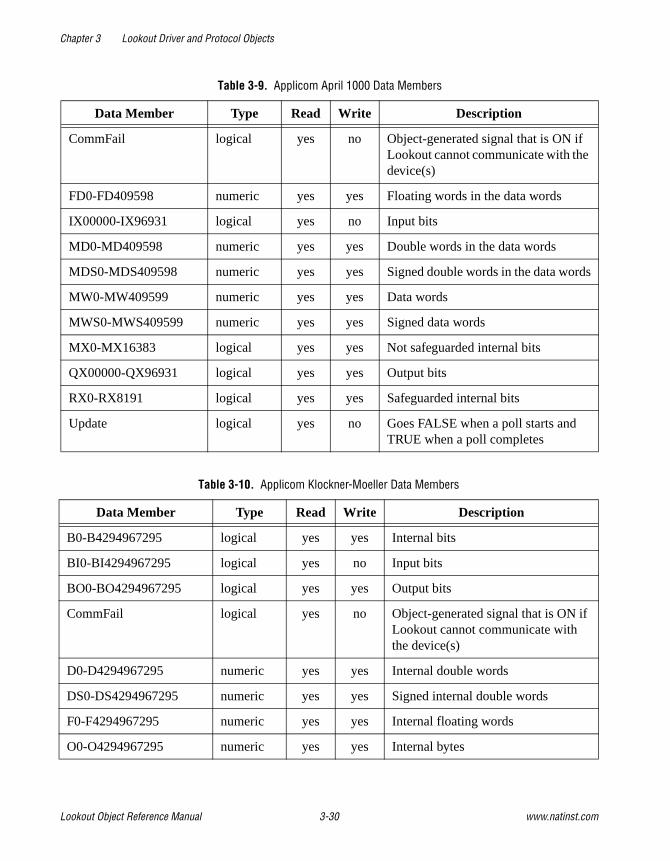
Chapter 3 Lookout Driver and Protocol Objects
Lookout Object Reference Manual 3-30 www.natinst.com
Table 3-9. Applicom April 1000 Data Members
Data Member Type Read Write Description
CommFail logical yes no Object-generated signal that is ON if Lookout cannot communicate with the device(s)
FD0-FD409598 numeric yes yes Floating words in the data words
IX00000-IX96931 logical yes no Input bits
MD0-MD409598 numeric yes yes Double words in the data words
MDS0-MDS409598 numeric yes yes Signed double words in the data words
MW0-MW409599 numeric yes yes Data words
MWS0-MWS409599 numeric yes yes Signed data words
MX0-MX16383 logical yes yes Not safeguarded internal bits
QX00000-QX96931 logical yes yes Output bits
RX0-RX8191 logical yes yes Safeguarded internal bits
Update logical yes no Goes FALSE when a poll starts and TRUE when a poll completes
Table 3-10. Applicom Klockner-Moeller Data Members
Data Member Type Read Write Description
B0-B4294967295 logical yes yes Internal bits
BI0-BI4294967295 logical yes no Input bits
BO0-BO4294967295 logical yes yes Output bits
CommFail logical yes no Object-generated signal that is ON if Lookout cannot communicate with the device(s)
D0-D4294967295 numeric yes yes Internal double words
DS0-DS4294967295 numeric yes yes Signed internal double words
F0-F4294967295 numeric yes yes Internal floating words
O0-O4294967295 numeric yes yes Internal bytes
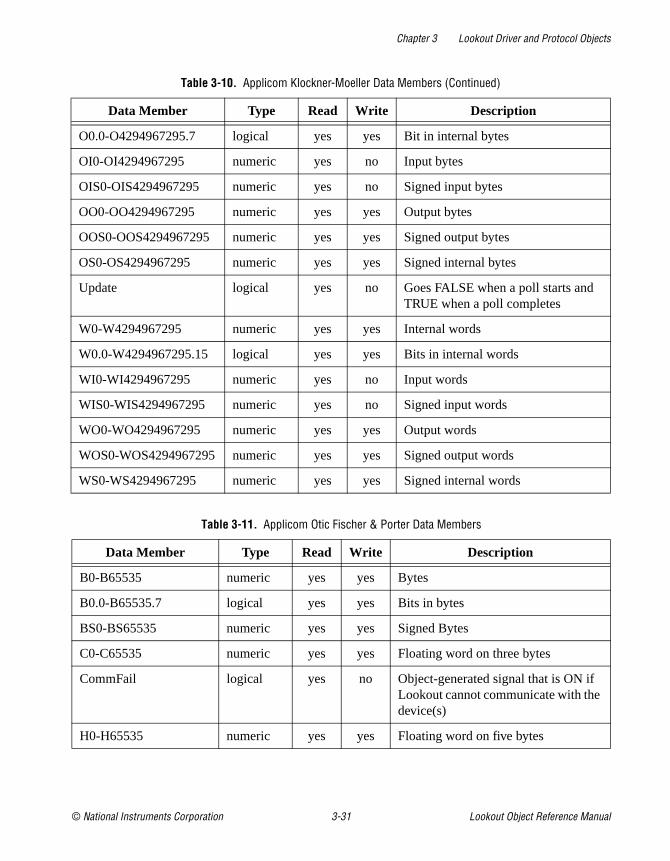
Chapter 3 Lookout Driver and Protocol Objects
© National Instruments Corporation 3-31 Lookout Object Reference Manual
O0.0-O4294967295.7 logical yes yes Bit in internal bytes
OI0-OI4294967295 numeric yes no Input bytes
OIS0-OIS4294967295 numeric yes no Signed input bytes
OO0-OO4294967295 numeric yes yes Output bytes
OOS0-OOS4294967295 numeric yes yes Signed output bytes
OS0-OS4294967295 numeric yes yes Signed internal bytes
Update logical yes no Goes FALSE when a poll starts and TRUE when a poll completes
W0-W4294967295 numeric yes yes Internal words
W0.0-W4294967295.15 logical yes yes Bits in internal words
WI0-WI4294967295 numeric yes no Input words
WIS0-WIS4294967295 numeric yes no Signed input words
WO0-WO4294967295 numeric yes yes Output words
WOS0-WOS4294967295 numeric yes yes Signed output words
WS0-WS4294967295 numeric yes yes Signed internal words
Table 3-11. Applicom Otic Fischer & Porter Data Members
Data Member Type Read Write Description
B0-B65535 numeric yes yes Bytes
B0.0-B65535.7 logical yes yes Bits in bytes
BS0-BS65535 numeric yes yes Signed Bytes
C0-C65535 numeric yes yes Floating word on three bytes
CommFail logical yes no Object-generated signal that is ON if Lookout cannot communicate with the device(s)
H0-H65535 numeric yes yes Floating word on five bytes
Table 3-10. Applicom Klockner-Moeller Data Members (Continued)
Data Member Type Read Write Description

Chapter 3 Lookout Driver and Protocol Objects
Lookout Object Reference Manual 3-32 www.natinst.com
L0-L65535 logical yes yes Bits
Update logical yes no Goes FALSE when a poll starts and TRUE when a poll completes
Table 3-12. Applicom Profibus DP Data Members
Data Member Type Read Write Description
B0-B4294967295 logical yes yes Internal bits
BI0-BI4294967295 logical yes no Input bits
BO0-BO4294967295 logical yes yes Output bits
CommFail logical yes no Object-generated signal that is ON if Lookout cannot communicate with the device(s)
D0-D4294967295 numeric yes yes Internal double words
DS0-DS4294967295 numeric yes yes Signed internal double words
F0-F4294967295 numeric yes yes Internal floating words
O0-O4294967295 numeric yes yes Internal bytes
O0.0-O4294967295.7 logical yes yes Bit in internal bytes
OI0-OI4294967295 numeric yes no Input bytes
OIS0-OIS4294967295 numeric yes no Signed input bytes
OO0-OO4294967295 numeric yes yes Output bytes
OOS0-OOS4294967295 numeric yes yes Signed output bytes
OS0-OS4294967295 numeric yes yes Signed internal bytes
Update logical yes no Goes FALSE when a poll starts and TRUE when a poll completes
W0-W4294967295 numeric yes yes Internal words
W0.0-W4294967295.15 logical yes yes Bits in internal words
WI0-WI4294967295 numeric yes no Input words
Table 3-11. Applicom Otic Fischer & Porter Data Members (Continued)
Data Member Type Read Write Description

Chapter 3 Lookout Driver and Protocol Objects
© National Instruments Corporation 3-33 Lookout Object Reference Manual
WIS0-WIS4294967295 numeric yes no Signed input words
WO0-WO4294967295 numeric yes yes Output words
WOS0-WOS4294967295 numeric yes yes Signed output words
WS0-WS4294967295 numeric yes yes Signed internal words
Table 3-13. Applicom Profibus FMS Data Members
Data Member Type Read Write Description
BID0-BID65535 logical yes yes Bits (simple variables)
BID0SUB0-BID65535SUB240
logical yes yes Bits
CommFail logical yes no Object-generated signal that is ON if Lookout cannot communicate with the device(s)
DID0-DID65535 numeric yes yes Doubles words (simple variables)
DID0SUB0-DID65535SUB60
numeric yes yes Doubles words
FID0-FID65535 numeric yes yes Floating words (simple variables)
FID0SUB0-FID65535SUB60
numeric yes yes Floating words
OID0-OID65535 numeric yes yes Bytes (simple variables)
OID0SUB0-OID65535SUB240
numeric yes yes Bytes
OID0SUBS0-OID65535SUBS240
numeric yes yes Signed bytes
OIDS0-OIDS65535 numeric yes yes Signed bytes (simple variables)
Update logical yes no Goes FALSE when a poll starts and TRUE when a poll completes
WID0-WID65535 numeric yes yes Words (simple variables)
Table 3-12. Applicom Profibus DP Data Members (Continued)
Data Member Type Read Write Description
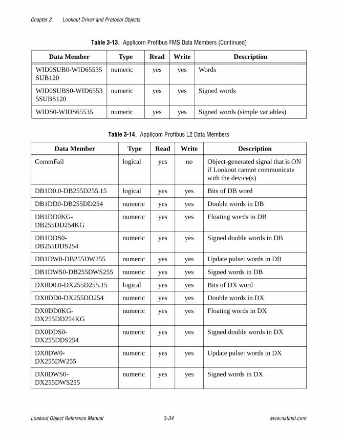
Chapter 3 Lookout Driver and Protocol Objects
Lookout Object Reference Manual 3-34 www.natinst.com
WID0SUB0-WID65535SUB120
numeric yes yes Words
WID0SUBS0-WID65535SUBS120
numeric yes yes Signed words
WIDS0-WIDS65535 numeric yes yes Signed words (simple variables)
Table 3-14. Applicom Profibus L2 Data Members
Data Member Type Read Write Description
CommFail logical yes no Object-generated signal that is ON if Lookout cannot communicate with the device(s)
DB1D0.0-DB255D255.15 logical yes yes Bits of DB word
DB1DD0-DB255DD254 numeric yes yes Double words in DB
DB1DD0KG-DB255DD254KG
numeric yes yes Floating words in DB
DB1DDS0-DB255DDS254
numeric yes yes Signed double words in DB
DB1DW0-DB255DW255 numeric yes yes Update pulse: words in DB
DB1DWS0-DB255DWS255 numeric yes yes Signed words in DB
DX0D0.0-DX255D255.15 logical yes yes Bits of DX word
DX0DD0-DX255DD254 numeric yes yes Double words in DX
DX0DD0KG-DX255DD254KG
numeric yes yes Floating words in DX
DX0DDS0-DX255DDS254
numeric yes yes Signed double words in DX
DX0DW0-DX255DW255
numeric yes yes Update pulse: words in DX
DX0DWS0-DX255DWS255
numeric yes yes Signed words in DX
Table 3-13. Applicom Profibus FMS Data Members (Continued)
Data Member Type Read Write Description

Chapter 3 Lookout Driver and Protocol Objects
© National Instruments Corporation 3-35 Lookout Object Reference Manual
F0.0-F255.7 logical yes yes Bits in flag bytes
FD0-FD255 numeric yes yes Double words in flag bytes
FD0KG-FD252KG numeric yes yes Floating words in flag bytes
FDS0-FDS255 numeric yes yes Signed double words in flag bytes
FW0-FW254 numeric yes yes Words in flag bytes
FWS0-FWS254 numeric yes yes Signed words in flag bytes
FY0-FY255 numeric yes yes Flag bytes
FYS0-FYS255 numeric yes yes Signed flag bytes
I0.0-I127.7 logical yes no Input bits
IB0-IB127 numeric yes no Input bytes
IBS0-IBS127 numeric yes no Signed input bytes
IW0-IW126 numeric yes no Input words
IWS0-IWS126 numeric yes no Signed input words
Q0.0-Q127.7 logical yes yes Output bits
QW0-QW126 numeric yes yes Output words
QWS0-QWS126 numeric yes yes Signed output words
QY0-QY127 numeric yes yes Output bytes
QYS0-QYS127 numeric yes yes Signed output bytes
S0.0-S4095.7 logical yes yes Bits in Sflags (internal bytes)
SD0-SD4095 numeric yes yes Floating words in Sflags
SD0KG-SD4092KG numeric yes yes Floating words in Sflags
SDS0-SDS4095 numeric yes yes Signed double words in Sflags
SW0-SW4094 numeric yes yes Words in Sflags (internal bytes)
SWS0-SWS4094 numeric yes yes Signed words in Sflags (internal bytes)
SY0-SY4095 numeric yes yes Sflags (internal bytes)
Table 3-14. Applicom Profibus L2 Data Members (Continued)
Data Member Type Read Write Description

Chapter 3 Lookout Driver and Protocol Objects
Lookout Object Reference Manual 3-36 www.natinst.com
SYS0-SYS4095 numeric yes yes Signed Sflags (internal bytes)
Update logical yes no Goes FALSE when a poll starts and TRUE when a poll completes
Table 3-15. Applicom Siemens S5 H1 Data Members
Data Member Type Read Write Description
CommFail logical yes no Object-generated signal that is on if Lookout cannot communicate with the device(s)
DB1D0.0 - DB255D255.15
logical yes yes Bits of DB word
DB1DD0 - DB255DD254
numeric yes yes Double words in DB
DB1DD0KG - DB255DD254KG
numeric yes yes Floating words in DB
DB1DDS0 - DB255DDS254
numeric yes yes Signed double words in DB
DB1DW0 - DB255DW255
numeric yes yes Update pulse: words in DB
DB1DWS0 - DB255DWS255
numeric yes yes Signed words in DB
DX0D0.0 - DX255D255.15
logical yes yes Bits of DX word
DX0DD0 - DX255DD254
numeric yes yes Double words in DX
DX0DD0KG - DX255DD254KG
numeric yes yes Floating words in DX
DX0DDS0 - DX255DDS254
numeric yes yes Signed double words in DX
DX0DW0 - DX255DW255
numeric yes yes Update pulse: words in DX
Table 3-14. Applicom Profibus L2 Data Members (Continued)
Data Member Type Read Write Description

Chapter 3 Lookout Driver and Protocol Objects
© National Instruments Corporation 3-37 Lookout Object Reference Manual
DX0DWS0 - DX255DWS255
numeric yes yes Signed words in DX
FD0 - FD255 numeric yes yes Double words in flag bytes
FD0KG - FD252KG numeric yes yes Floating words in flag bytes
FDS0 - FDS255 numeric yes yes Signed double words in flag bytes
FW0 - FW254 numeric yes yes Words in flag bytes
FWS0 - FWS254 numeric yes yes Signed words in flag bytes
FY0 - FY255 numeric yes yes Flag bytes
FYS0 - FYS255 numeric yes yes Signed flag bytes
I0.0 - I127.7 logical yes no Input bits
IB0 - IB127 numeric yes no Input bytes
IBS0 - IBS127 numeric yes no Signed input bytes
IW0 - IW126 numeric yes no Input words
IWS0 - IWS126 numeric yes no Signed input words
Q0.0 - Q127.7 logical yes yes Output bits
QW0 - QW126 numeric yes yes Output words
QWS0 - QWS126 numeric yes yes Signed output words
QY0 - QY127 numeric yes yes Output bytes
QYS0 - QYS127 numeric yes yes Signed output bytes
S0.0 - S4095.7 logical yes yes Bits in Sflags (internal bytes)
SD0 - SD4095 numeric yes yes Floating words in Sflags
SD0KG - SD4092KG numeric yes yes Floating words in Sflags
SDS0 - SDS4095 numeric yes yes Signed double words in Sflags
SW0 - SW4094 numeric yes yes Words in Sflags (internal bytes)
SWS0 - SWS4094 numeric yes yes Signed words in Sflags (internal bytes)
Table 3-15. Applicom Siemens S5 H1 Data Members (Continued)
Data Member Type Read Write Description

Chapter 3 Lookout Driver and Protocol Objects
Lookout Object Reference Manual 3-38 www.natinst.com
SY0 - SY4095 numeric yes yes Sflags (internal bytes)
SYS0 - SYS4095 numeric yes yes Signed Sflags (internal bytes)
Update logical yes no False during Polling sequence
Table 3-16. Applicom SAIA SBus Data Members
Data Member Type Read Write Description
CommFail logical yes no Object-generated signal that is ON if Lookout cannot communicate with the device(s)
DB0Q0-DB7999Q7999 numeric yes yes Floating data block
DB0R0-DB7999R7999 numeric yes yes Binary data block
DB0R0.0-DB7999R7999.31 logical yes yes Bits in binary data block
DB0R0.0-DB7999R7999.31 logical yes yes Bits in binary data block
F0-F8091 logical yes yes Flags
I0-I8091 logical yes no Input
O0-O8091 logical yes yes Output
Q0-Q4095 numeric yes yes Floating registers
R0-R4095 numeric yes yes Binary registers
R0.0-R4095.31 logical yes yes Bits in binary registers
RS0-RS4095 numeric yes yes Signed binary registers
Update logical yes no Goes FALSE when a poll starts and TRUE when a poll completes
Table 3-15. Applicom Siemens S5 H1 Data Members (Continued)
Data Member Type Read Write Description

Chapter 3 Lookout Driver and Protocol Objects
© National Instruments Corporation 3-39 Lookout Object Reference Manual
Table 3-17. Applicom Siemens S5 AS511 Data Members
Data Member Type Read Write Description
CommFail logical yes no Object-generated signal that is ON if Lookout cannot communicate with the device(s)
DB1D0.0-DB255D255.15 logical yes yes Bits of DB word
DB1DD0-DB255DD254 numeric yes yes Double words in DB
DB1DD0KG-DB255DD254KG numeric yes yes Floating words in DB
DB1DDS0-DB255DDS254 numeric yes yes Signed double words in DB
DB1DW0-DB255DW255 numeric yes yes Update pulse: words in DB
DB1DWS0-DB255DWS255 numeric yes yes Signed words in DB
DX0D0.0-DX255D255.15 logical yes yes Bits of DX word
DX0DD0-DX255DD254 numeric yes yes Double words in DX
DX0DD0KG-DX255DD254KG numeric yes yes Floating words in DX
DX0DDS0-DX255DDS254 numeric yes yes Signed double words in DX
DX0DW0-DX255DW255 numeric yes yes Update pulse: words in DX
DX0DWS0-DX255DWS255 numeric yes yes Signed words in DX
F0.0-F255.7 logical yes yes Bits in flag bytes
FD0-FD255 numeric yes yes Double words in flag bytes
FD0KG-FD252KG numeric yes yes Floating words in flag bytes
FDS0-FDS255 numeric yes yes Signed double words in flag bytes
FW0-FW254 numeric yes yes Words in flag bytes
FWS0-FWS254 numeric yes yes Signed words in flag bytes
FY0-FY255 numeric yes yes Flag bytes
FYS0-FYS255 numeric yes yes Signed flag bytes
I0.0-I127.7 logical yes no Input bits
IB0-IB127 numeric yes no Input bytes

Chapter 3 Lookout Driver and Protocol Objects
Lookout Object Reference Manual 3-40 www.natinst.com
IBS0-IBS127 numeric yes no Signed input bytes
IW0-IW126 numeric yes no Input words
IWS0-IWS126 numeric yes no Signed input words
Q0.0-Q127.7 logical yes yes Output bits
QW0-QW126 numeric yes yes Output words
QWS0-QWS126 numeric yes yes Signed output words
QY0-QY127 numeric yes yes Output bytes
QYS0-QYS127 numeric yes yes Signed output bytes
S0.0-S4095.7 logical yes yes Bits in Sflags (internal bytes)
SD0-SD4095 numeric yes yes Floating words in Sflags
SD0KG-SD4092KG numeric yes yes Floating words in Sflags
SDS0-SDS4095 numeric yes yes Signed double words in Sflags
SW0-SW4094 numeric yes yes Words in Sflags (internal bytes)
SWS0-SWS4094 numeric yes yes Signed words in Sflags (internal bytes)
SY0-SY4095 numeric yes yes Sflags (internal bytes)
SYS0-SYS4095 numeric yes yes Signed Sflags (internal bytes)
Update logical yes no Goes FALSE when a poll starts and TRUE when a poll completes
Table 3-18. Applicom Siemens S7 MPI Data Members
Data Member Type Read Write Description
A0.0-A65535.7 logical yes yes Output bits
AB0-AB65535 numeric yes yes Output bytes
ABS0-ABS65535 numeric yes yes Signed output bytes
Table 3-17. Applicom Siemens S5 AS511 Data Members (Continued)
Data Member Type Read Write Description

Chapter 3 Lookout Driver and Protocol Objects
© National Instruments Corporation 3-41 Lookout Object Reference Manual
AW0-AW65534 numeric yes yes Output words
AWS0-AWS65534 numeric yes yes Signed output words
CommFail logical yes no Object-generated signal that is ON if Lookout cannot communicate with the device(s)
DB0.DBD0-DB32767.DBD65532
numeric yes yes Double words in DB
DB0.DBD0F-DB32767.DBD65532F
numeric yes yes Floating words in DB
DB0.DBDS0-DB32767.DBDS65532
numeric yes yes Signed double words in DB
DB0.DBW0-DB32767.DBW65534
numeric yes yes Words in DB
DB0.DBWS0-DB32767.DBWS65534
numeric yes yes Signed words in DB
DB0DBB0-DB32767.DBB65535
numeric yes yes Bytes in DB
DB0DBBS0-DB32767.DBBS65535
numeric yes
yes Signed bytes in DB
DB1.DBX0.0-DB8191.DB65535.7
logical yes yes Bits in DB byte
E0.0-E65535.7 logical yes no Input bits
EB0-EB65535 numeric yes no Input bytes
EBS0-EBS65535 numeric yes no Signed input bytes
EW0-EW65534 numeric yes no Input words
EWS0-EWS65534 numeric yes no Signed input words
M0.0-M65535.7 logical yes yes Bits in flag bytes
MB0-MB65535 numeric yes yes Flag bytes
MBS0-MBS65535 numeric yes yes Signed flag bytes
Table 3-18. Applicom Siemens S7 MPI Data Members (Continued)
Data Member Type Read Write Description

Chapter 3 Lookout Driver and Protocol Objects
Lookout Object Reference Manual 3-42 www.natinst.com
MD0-MD65532 numeric yes yes Double words in flag bytes
MD0F-MD65532F numeric yes yes Floating words in flag bytes
MDS0-MDS65532 numeric yes yes Signed double words in flag bytes
MW0-MW65534 numeric yes yes Words in flag bytes
MWS0-MWS65534 numeric yes yes Signed words in flag bytes
Update logical yes no Goes FALSE when a poll starts and TRUE when a poll completes
Table 3-19. Applicom Siemens S7 PPI Data Members
Data Member Type Read Write Description
A0.0-A65535.7 logical yes yes Output bits
AB0-AB65535 numeric yes yes Output bytes
ABS0-ABS65535 numeric yes yes Signed output bytes
AW0-AW65534 numeric yes yes Output words
AWS0-AWS65534 numeric yes yes Signed output words
CommFail logical yes no Object-generated signal that is ON if Lookout cannot communicate with the device(s)
DB0.DBD0-DB32767.DBD65532
numeric yes yes Double words in DB
DB0.DBD0F-DB32767.DBD65532F
numeric yes yes Floating words in DB
DB0.DBDS0-DB32767.DBDS65532
numeric yes yes Signed double words in DB
DB0.DBW0-DB32767.DBW65534
numeric yes yes Words in DB
DB0.DBWS0-DB32767.DBWS65534
numeric yes yes Signed words in DB
Table 3-18. Applicom Siemens S7 MPI Data Members (Continued)
Data Member Type Read Write Description

Chapter 3 Lookout Driver and Protocol Objects
© National Instruments Corporation 3-43 Lookout Object Reference Manual
DB0DBB0-DB32767.DBB65535
numeric yes yes Bytes in DB
DB0DBBS0-DB32767.DBBS65535
numeric yes yes Signed bytes in DB
DB1.DBX0.0-DB8191.DB65535.7
logical yes yes Bits in DB byte
E0.0-E65535.7 logical yes no Input bits
EB0-EB65535 numeric yes no Input bytes
EBS0-EBS65535 numeric yes no Signed input bytes
EW0-EW65534 numeric yes no Input words
EWS0-EWS65534 numeric yes no Signed input words
M0.0-M65535.7 logical yes yes Bits in flag bytes
MB0-MB65535 numeric yes yes Flag bytes
MBS0-MBS65535 numeric yes yes Signed flag bytes
MD0-MD65532 numeric yes yes Double words in flag bytes
MD0F-MD65532F numeric yes yes Floating words in flag bytes
MDS0-MDS65532 numeric yes yes Signed double words in flag bytes
MW0-MW65534 numeric yes yes Words in flag bytes
MWS0-MWS65534 numeric yes yes Signed words in flag bytes
Update logical yes no Goes FALSE when a poll starts and TRUE when a poll completes
Table 3-20. Applicom Siemens H1 Data Members
Data Member Type Read Write Description
C1-C2097152 logical yes yes Bits
CommFail logical yes no Object-generated signal that is ON if Lookout cannot communicate with the device(s)
Table 3-19. Applicom Siemens S7 PPI Data Members (Continued)
Data Member Type Read Write Description

Chapter 3 Lookout Driver and Protocol Objects
Lookout Object Reference Manual 3-44 www.natinst.com
DCP1-DCP65536 numeric yes yes Drum count preset
DSC1-DSC65536 numeric yes yes Drum step current
DSP1-DSP65536 numeric yes yes Drum step preset
K1-K2097152 numeric yes yes Constant words
K1.0-K2097152.15 logical yes yes Bits in constant words
KF1-KF2097151 numeric yes yes Floating constant words
KS1-KS2097152 numeric yes yes Signed constant words
STW1-STW65536 numeric yes yes System status words
TCC1-TCC65536 numeric yes yes Timer/counter current
TCP1-TCP65536 numeric yes yes Timer/counter preset
Update logical yes no Goes FALSE when a poll starts and TRUE when a poll completes
V1-V2097152 numeric yes yes Internal words
V1.0-V2097152.15 logical yes yes Bits in internal words
VD1-VD2097151 numeric yes yes Internal double words
VDS1-VDS2097151 numeric yes yes Signed internal double words
VF1-VF2097151 numeric yes yes Floating words
VS1-VS2097152 numeric yes yes Signed internal words
WSY1-WYS2097152 numeric yes yes Signed output words
WX1-WX2097152 numeric yes yes Input words
WXS1-WXS2097152 numeric yes yes Signed input words
WY1-WY2097152 numeric yes yes Output words
X1-X2097152 logical yes no Input bits
Y1-Y2097152 logical yes yes Output bits
Table 3-20. Applicom Siemens H1 Data Members (Continued)
Data Member Type Read Write Description

Chapter 3 Lookout Driver and Protocol Objects
© National Instruments Corporation 3-45 Lookout Object Reference Manual
General Information on Using the Applicom drivers for LookoutThe Applicom drivers for Lookout are all contained in APPLICOM.CBX (16- or 32-bit) which is designed to work with the Applicom server software distributed with every Applicom card. These drivers assume that you have version 2.9 or later of the Applicom software installed on the same computer under the same operating system as your copy of Lookout. TheAPPLICOM.CBX file presently supports 12 different object classes corresponding to 12 different protocols or object types.
Before you start using Lookout with Applicom, you must follow certain configuration and testing procedures to ensure that Lookout can
Table 3-21. Applicom Telemecanique Data Members
Data Member Type Read Write Description
B0-B4095 logical yes yes Internal bits
CommFail logical yes no Object-generated signal that is ON if Lookout cannot communicate with the device(s)
DW0-DW32766 numeric yes yes Internal double words
DWS0-DWS32766 numeric yes yes Signed internal double words
FW0-FW32766 numeric yes yes Internal floating words
I00.0-IF7.F logical yes no Input bits
IW00.0-IWF7.7 numeric yes no Words in input registers
IWS00.0-IWSF7.7 numeric yes no Signed words in input registers
O00.0-OF7.F logical yes yes Output bits
OW00.0-OWF7.7 Special
numeric yes yes Words in output registers
OWS00.0-OWSF7.7 Special
numeric yes yes Signed words in output registers
Update logical yes no Goes FALSE when a poll starts and TRUE when a poll completes
W0-W32767 numeric yes yes Internal words
WS0-WS32767 numeric yes yes Signed internal words

Chapter 3 Lookout Driver and Protocol Objects
Lookout Object Reference Manual 3-46 www.natinst.com
communicate with your devices. The steps include configuration, loading, testing, and if you choose, cyclic function configuration.
First, however, take special notice of the two different modes for using the Lookout Applicom driver–Image and Local. The distinction between these two modes is crucial to using the Lookout Applicom object classes.
Applicom Local and Image ModesYou can configure the Applicom server software to constantly poll a remote device and store data in a database onboard your Applicom card. You use Local mode to access that data.
In Lookout, you address the data using a generic addressing scheme (as a bit number, or word number, and so on.). The Applicom card takes care of polling the device and writing out new values to registers on the device. If there are any problems in communicating with the device, an error code may be generated and stored in a specified database location. The Lookout driver can then use the data at that location to generate alarms.
In Image mode you address data on the remote device according to the addressing scheme commonly used with the particular class of devices. In this mode, Lookout asks for data directly from a remote device and is notified of communication errors when they arise. The Lookout Applicom driver then retries the particular data transfer repeatedly, generating alarms when the data transfer continues to fail.
You use the Applicom Local object class for local mode functionality, and the other device- or protocol-specific object classes for image mode functionality. You can use Applicom Local concurrently with any of the other Applicom classes.
The Image mode classes are the typical way to use the Applicom driver for most applications. However, the Local mode provides a convenient way to achieve two goals: providing access to data from multiple applications (because any application may use the Applicom functions to access the local mode database); and allowing inputs from one device connected to a card to be written to outputs on another device connected to the same card without the interference of the Windows operating system or the client application (for example, Lookout).

Chapter 3 Lookout Driver and Protocol Objects
© National Instruments Corporation 3-47 Lookout Object Reference Manual
Configuration of the Applicom ServerAfter you install the Applicom server software, you must first configure it using the PCConf utility provided as part of the Applicom software. Refer to the Software Installation section of your Applicom documentation for details on using Applicom software. You use the PCConf utility to set the basic types of devices connected to the Applicom card and the protocols used to connect to them. You also set all the communication parameters with this program.
While configuring your system with PCConf, make note of the Channel number and Equipment number for the device(s) you are using Lookout to communicate with. You will need these values as parameters when you create Lookout objects in Image mode.
Loading of the Applicom ServerAfter you configure the Applicom Server, you must download the appropriate firmware module to the card and then configure it. You do this by running the Applicom program PCInit . The configuration software notifies you at this time if there is any physical problem with the installation of the card.
You must run PCInit every time you restart the computer if you plan to communicate with the Applicom card and connected devices during that session. Because of this, you may consider putting a shortcut to this program in the Startup program group.
At this point, the Applicom server should be ready to communicate with Lookout and with the remote devices connected to the card. Before starting Lookout and attempting to communicate, you should first test the connections using some of the Applicom programs.
Testing the Applicom ServerThe ReadWait program in the Applicom server group is a good example of a program that can be used to test the connectivity of the Applicom card with a remote device. You can also use WritWait , Essai , and Essaigb . Try performing read or write operations using these programs to test whether you can perform basic data transfer operations between the card and the devices. If these tests fail, Lookout will not be able to communicate with the devices either.
Chapter 3 Lookout Driver and Protocol Objects
Lookout Object Reference Manual 3-48 www.natinst.com
If your tests succeed and Lookout fails to communicate with the Applicom devices, it is likely that the problem is in the Lookout object configuration. Because the Applicom programs require you to use the channel and equipment numbers from the PCConf program, testing helps you verify that you have the correct numbers.
Creating the Cyclic FunctionsThere is only one more step before you start using the Lookout drivers, and it is required only if you are planning to use the Applicom Local object class. In that case, you must first configure the cyclic functions that exchange data between the onboard database of the Applicom card and the remote devices.
You do this by using either the Applicom CreateCyc or PCCyc utility programs. These programs require that you enter a channel number, an equipment number, and whether the required operation is a read or a write. You also enter the address of the data on the remote device and the requested address of the data in the database. Once you have created and saved the cyclic functions, you can test them using the GetDB and SetDB programs in the Applicom server.
After you verify that the card can communicate with the remote device, you can start using Lookout. Create a Lookout object of the appropriate class, enter the required parameters, and start communicating with the remote device.
Special Instructions on Using the Applicom Local Object ClassThe Applicom Local object class behaves very differently from the Image mode object classes. To use it, you must have configured cyclic functions on your Applicom card using the Applicom PCCyc or CreateCyc programs.
After you configure these functions, you can create one or more Applicom Local objects in Lookout to read from or write to the Applicom database directly. The syntax is a generic syntax which does not correspond with the syntax you use with the PLC. The address you specify in Lookout must be the address of the data on the Applicom board, not the address on the remote device.

Chapter 3 Lookout Driver and Protocol Objects
© National Instruments Corporation 3-49 Lookout Object Reference Manual
You can also specify a status word in the PCCyc program for each cyclic function you create. You can then specify a single status address in the object creation/modification dialog box for Applicom Local to get Lookout alarms any time the corresponding cyclic function is unable to exchange data successfully.
The Applicom Local object class is compatible with the other object classes so that you can create multiple Applicom object classes of any type and use them all at the same time.
Applicom Status MessagesThe requested address is incorrect
You have requested data for an invalid address. Check the address and try again. For further details check the Applicom documentation for an explanation of error code 2.
Incorrect data type
The type of the data on the device is not compatible with the requested type. This may occur for different reasons in different protocols. For further details check the Applicom documentation for an explanation of error code 3.
Irretrievable data
The data you are trying to access is irretrievable. Please check that the device is connected and has all the appropriate models. For further details check the Applicom documentation for an explanation of error code 4.
Response timed out
The device did not respond to a message within the time-out period. Check that the device is connected. For further details, check the Applicom documentation for an explanation of error code 33.
Check word or parity fault
Check the channel and target equipment configuration and the wiring to the equipment. For further details, check the Applicom documentation for an explanation of error code 34.
Data not available in cyclic read
There was an error in reading from the card. Contact National Instruments technical support if this error occurs.

Chapter 3 Lookout Driver and Protocol Objects
Lookout Object Reference Manual 3-50 www.natinst.com
Equipment not configured
Configure the equipment with PCConf. If you have already done so, check that you are using the correct (logical) equipment ID, as configured in PCConf.
Deferred read or write request when deferred request register is full
There was an error in writing to the card. Contact National Instruments technical support if this error occurs.
Deferred request transfer attempt with transdif when request register is empty
There was an error in writing to the card. Contact National Instruments technical support if this error occurs.
Communication software not initialized
The Applicom board was not initialized using the PCInit software. Close Lookout, run PCInit and try running Lookout again.
Board number not configured
The board number you are attempting to use is not one that has been configured. Please check the configuration using PCConf.
No Applicom interface
There is no Applicom interface present. Check that PCInit executed correctly.
Timeout elapsed. Message lost
A communication problem occurred that may be related to the configuration of the remote equipment or the bus that the equipment is on. For further details, check the Applicom documentation for an explanation of error code 55.
Negative acknowledgment (NAK) from equipment
A message was received by the destination equipment but not processed due to lack of resources. For further details, check the Applicom documentation for an explanation of error code 56.
Communication refused by the equipment.
The equipment is not responding to communication requests. This may be caused by a misconfigured device or by a bad connection with the Applicom card. Check the device configuration, check the Applicom configuration and use the Applicom utilities to check that there is communication between the two.

Chapter 3 Lookout Driver and Protocol Objects
© National Instruments Corporation 3-51 Lookout Object Reference Manual
Bad frame received
The remote device is not behaving correctly. Check the configuration of the device.
Errorcode ID: refer to Applicom documentation
Your application has returned an error specific to your Applicom device. Consult your Applicom documentation for further information.

Chapter 3 Lookout Driver and Protocol Objects
Lookout Object Reference Manual 3-52 www.natinst.com
AquatrolAquatrol is a protocol driver class Lookout uses to communicate with Aquatrol W1500 controllers.
Figure 3-7. Aquatrol Definition Parameters Dialog Box
Address is the address of the RTU as configured on the device. The address can be in the range of 100 to 999 inclusive.
Model is W1500 only at this time.
Serial port specifies which port the object uses for communication to the external device. This does not specify the communication type. Communication type is determined by the Options»Serial Ports… command.
Data rate, Parity, Data bits, and Stop bits reference the settings on the hardware device.
Phone specifies the number to be dialed if the serial port setting is configured for dial-up. This number only applies to the individual protocol object.
PollRate is a numeric expression that determines how often to poll the device. Lookout converts the numeric value of PollRate into a time signal that represents days and fractions of a day. Aquatrol then polls the device at the specified time interval. Normally, this is a time constant such as

Chapter 3 Lookout Driver and Protocol Objects
© National Instruments Corporation 3-53 Lookout Object Reference Manual
0:01 (one second). See the Numeric Data Members section in Chapter 2, How Lookout Works, of the Getting Started with Lookout manual for information on entering time constants.
Poll is a logical expression. When this expression changes from false to true, Lookout polls the device. You can use a simple expression like the signal from a pushbutton, or a complex algorithm.
Communication alarm priority determines the priority level of object-generated alarms (0 – 10).
Retry attempts specifies the consecutive number of times Lookout attempts to establish communications with a device if it is not getting a valid response. After it tries the number of Retry attempts specified, the Aquatrol object generates an alarm and releases the communication port back to the communications service which then moves on to the next device in the polling queue (if any).
Receive timeout is the time delay Lookout uses in waiting for a response from a device before retrying the request.
The Skip every… setting instructs Lookout not to poll a device it has lost communication with on every scheduled poll. Instead, Lookout skips the device in the polling cycle accordingly. Once communications have been reestablished, the device is polled on its regular cycle.
RTU Configuration Dialog Box
Figure 3-8. RTU Configuration Dialog Box
You must configure Lookout to match the configuration in your Aquatrol device.
Digital (In/Out) specifies configuration for the number of discrete I/O.

Chapter 3 Lookout Driver and Protocol Objects
Lookout Object Reference Manual 3-54 www.natinst.com
Analogs (In/Out) specifies configuration for the number of analog I/O.
Totalizers specifies configuration for the number of totalizers.
Start specifies configuration for the number of start counters.
Runtime specifies configuration for the number of runtime counters.
Repeater Address is the final destination address if a repeater is being used.
Note The Aquatrol must be configured with all I/O grouped together by kind. Digital inputs must be the first physical inputs on the device, followed by digital outputs. Analog inputs are next, followed by analog outputs. If you do not configure the I/O this way, you can receive invalid data.
Aquatrol Data MembersAll readable and writable members (inputs/outputs), polling instructions, read/write blocking, serial port usage, and so on, are bundled with the object. Therefore, as soon as you create an Aquatrol object you immediately have access to all the object data members (see data member list in Table 3-22).
Note Lookout protocol driver objects automatically generate an efficient read/write blocking scheme based on the inputs and outputs being used in your process file. You are not required to build your own I/O blocking table.
Table 3-22. Aquatrol Data Members
Data Member Type Read Write Description
AI1-AI48 numeric yes no Analog Input, 16 bit.
AO1-AO48 numeric no yes Analog Output, 16 bit.
ColdRestart logical yes no True if the device power has cycled on/off or the reset button has been pushed.
CommFail logical yes no True if serial communications have failed.

Chapter 3 Lookout Driver and Protocol Objects
© National Instruments Corporation 3-55 Lookout Object Reference Manual
Aquatrol Status MessagesNo response within timeout period
No response within timeout period for repeated message. Lookout did not received the expected response within the Receive timeout period. The object sent an inquiry and received an acknowledgment, but the device did not send an expected response to the request. This might happen if the response was interrupted. You may have to increase Receive timeout.
Frame Error (garbled): Invalid destination address
Lookout has received a frame with an invalid return address. Make sure that no duplicate addresses exist on the Aquatrol network.
ConfigError logical yes no True if the configuration of the device does not match the configuration set in the configuration dialog of the Aquatrol device.
DataFail logical yes no True if the device has had a data failure.
DI1-DI48 logical yes no Discrete Input, 1 bit.
DO1-DO48 logical no yes Discrete Output, 1 bit.
EEPROMerror logical yes no True if the device has an EEPROM error.
LowBattery logical yes no True if the device has a low battery.
Poll logical no yes True initiates a Poll sequence.
PollRate numeric no yes Time interval of Polling sequence.
PowerFail logical yes no True if there is no power to the device.
R1-R48 numeric yes no Runtimes, 16 bit.
S1-S48 numeric yes no Starts, 16 bit.
T1-T48 numeric yes no Totalizers, 16 bit.
Update logical yes no False during Polling sequence.
WarmRestart logical yes no True if the device has been reset locally.
Table 3-22. Aquatrol Data Members (Continued)
Data Member Type Read Write Description

Chapter 3 Lookout Driver and Protocol Objects
Lookout Object Reference Manual 3-56 www.natinst.com
Frame Error (garbled): Invalid source address
Lookout has received a frame from a device that you are not actively polling. Make sure that there is only one outstanding master request at a time.
Frame Error (garbled): Invalid message length for configuration
Lookout has received a frame whose length conflicts with the length expected based on the configuration settings in the Aquatrol device configuration dialog box.
Frame Error (garbled): Invalid CRC
Lookout has received a frame with an invalid CRC (cyclic redundancy check). Check for signal noise on Aquatrol network.
Invalid discrete address #: Check configuration settingsInvalid analog address #: Check configuration settingsInvalid runtime address #: Check configuration settingsInvalid start address #: Check configuration settingsInvalid totalizer address #: Check configuration settings
All these errors mean that a I/O point being either read or written is out of range with respect to the configuration set in the Aquatrol device configuration dialog box.
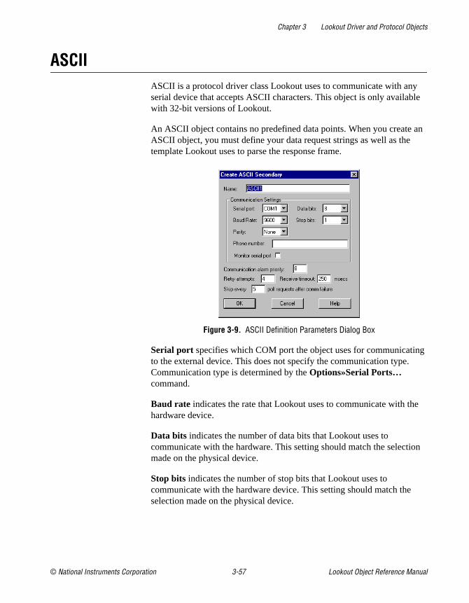
Chapter 3 Lookout Driver and Protocol Objects
© National Instruments Corporation 3-57 Lookout Object Reference Manual
ASCIIASCII is a protocol driver class Lookout uses to communicate with any serial device that accepts ASCII characters. This object is only available with 32-bit versions of Lookout.
An ASCII object contains no predefined data points. When you create an ASCII object, you must define your data request strings as well as the template Lookout uses to parse the response frame.
Figure 3-9. ASCII Definition Parameters Dialog Box
Serial port specifies which COM port the object uses for communicating to the external device. This does not specify the communication type. Communication type is determined by the Options»Serial Ports… command.
Baud rate indicates the rate that Lookout uses to communicate with the hardware device.
Data bits indicates the number of data bits that Lookout uses to communicate with the hardware. This setting should match the selection made on the physical device.
Stop bits indicates the number of stop bits that Lookout uses to communicate with the hardware device. This setting should match the selection made on the physical device.

Chapter 3 Lookout Driver and Protocol Objects
Lookout Object Reference Manual 3-58 www.natinst.com
Parity indicates the parity that Lookout uses to communicate with the hardware device. This setting should match the selection made on the physical device.
Phone number specifies the number to be dialed if the selected serial port is configured for dial-up. This number only applies to the individual protocol object.
Monitor Serial Port specifies whether you can receive unsolicited frames.
Communication alarm priority determines the priority level of alarms generated by the ASCII object. Such alarms are typically related to communications with the physical device.
Retry attempts specifies the number of times Lookout attempts to establish communications with a device if it is not getting a valid response. After it tries the number of Retry attempts specified, the ASCII object generates an alarm and releases the communication port back to the communications service which then moves on to the next device in the polling queue (if any). Refer to Chapter 3, Serial Communications, in the Lookout Developer’s Manual for more information.
Receive timeout is the amount of time Lookout waits for a response from a device before retrying the request.
The Skip every N poll requests after comm failure setting instructs Lookout not to poll a device it has lost communication with on every scheduled poll. Instead, Lookout polls the device only once in the specified number of poll cycles. Once communication has been reestablished, the device is polled on its regular cycle.
ASCII Data Members
Table 3-23. ASCII Data Members
Data Member Type Read Write Description
CommFail logical yes no Object-generated signal that is on if Lookout cannot communicate with the device(s).
OffHook logical no yes Keeps the driver from releasing the serial port.
Request text yes no Exact request frame sent.

Chapter 3 Lookout Driver and Protocol Objects
© National Instruments Corporation 3-59 Lookout Object Reference Manual
RequestFormat text no yes Format used to create request frame.
Response text yes no Exact response frame received.
ResponseFormat text no yes Format used to parse response frame.
RQSum:1:1 - RQSum255:255
numeric yes no Request byte sum
RQV1, RQV512 numeric no yes Variable list used to populate request frame with numeric values.
RQV1.logical, RQV512.logical
logical no yes Variable list used to populate request frame with logical values.
RQV1.txt, RQV512.txt text no yes Variable list used to populate request frame with text values.
RSFilter text no yes All characters in this string will be filtered out of the incoming response before processing.
RSSum1:1 - RSSum255:255
numeric yes no Response byte sum
RSV1, RSV512 numeric yes no Variable list used to store values retrieved from response frame.
RSV1.logical, RSV512.logical
logical yes no Variable list used to store values retrieved from response frame.
RSV1.txt, RSV512.txt text yes no Variable list used to store values retrieved from response frame.
Send logical no yes Sends request frame.
Update logical yes no Object-generated signal that pulses low each time it polls the device.
RSVn, RSVn.txt and RSVn.logical all represent the same value in different formsRQVn, RQVn.txt and RQVn.logical all represent the same value in different forms
Table 3-23. ASCII Data Members (Continued)
Data Member Type Read Write Description

Chapter 3 Lookout Driver and Protocol Objects
Lookout Object Reference Manual 3-60 www.natinst.com
Request and Response Format StringsThe request and response format strings consist of static characters and markers that control how the request and response frames respectively are formatted or decoded. The request format string is used to create the request frame, which is sent to the device, while the response format string is used to decode the response frame, which comes from the device.
Static characters in the format strings are reproduced exactly in the request or response frame. Markers specify the location within the frame and type of data which should be found there, such as five characters read as an unsigned integer, for example. The ASCII object constructs a request frame by processing the sequence of static characters and markers in the request format string, and including data from RQV data members.
The response format string decodes a response frame using an analogous process, storing the results in RSV data members.
To construct a request frame, the ASCII object parses the request format string character by character. Static characters are copied directly to the request frame. When a marker is encountered the ASCII object reads a value from the appropriate RQV variable and places it into the request frame.
There are 512 RQV and RSV values provided for in the ASCII object data member collection. The first marker in a format string uses the value from RQV1 (or RQV1.txt or RQV1.logical), the next marker uses the value RQV2, and so on. Values taken from Response strings are stored in RSV data members in the same way.
Keep in mind that writing into RQV1 changes the value both for RQV1.text and RQV1.logical. Their only difference is the format in which they are represented. The same principle applies to the RSV data members.
Note There is no precedence to the order in which multiple objects connected to the same variable number initialize upon opening the process file. Consider, for example, the case in which a Pot object is connected to RQV1 while a TextEntry object is connected to RQV1.txt. You should take care to initialize such variables to the proper value after opening a process file.
To decode a response frame, the ASCII object compares the response frame to the response format string character by character. The static characters in the response frame must match those in the response format string or the decoding process terminates. Static characters are, in effect, discarded

Chapter 3 Lookout Driver and Protocol Objects
© National Instruments Corporation 3-61 Lookout Object Reference Manual
by the ASCII object as they are matched between the response format string and the response frame.
When the ASCII object encounters a marker, it places the data indicated by the marker into the appropriate RSV data member.
The conversion of a portion of the response frame to a data type specified by a marker in the response format string must be valid, or the process will terminate.
If nothing halts the process, decoding terminates when the end of the response frame string is reached.
There are examples of both request frames and response frames at the end of this section, but for the examples to make sense, you must first understand the ASCII object markers.
ACSII Object MarkersThe general format for a marker is:
%[width][type]
Each field in the marker format is a single character or a number signifying a particular format option.
The % sign denotes the beginning of the marker. For example, to specify that a percent-sign character is a static character part of the frame, use %%.
Width is a positive decimal integer specifying the number of characters that particular value occupies in the frame. By default ASCII pads the value with blank spaces if the value takes up fewer characters than the value specified by width. Including a 0 before the width value forces the ASCII object to pad with zeroes instead of blank spaces.
Type determines whether the field is interpreted as a character, a string, or a number.
Table 3-24. Data Types Allowed by ASCII
Character Data Type
c Character
d Decimal integer
O, o Octal

Chapter 3 Lookout Driver and Protocol Objects
Lookout Object Reference Manual 3-62 www.natinst.com
The simplest format specification contains only the percent sign and a type character (for example, %s). That would place the value in the response frame in the RSV1.txt data member.
The request format string also has a precision value in the form %[width].[precision][type] . This specifies the number of digits to the right of the decimal point, if any, in the request frame. If you use a float (%f) and do not specify a precision value, the ASCII object assumes a default of 6.
Characters are converted and stored in RSV data members from response frames in the order they are encountered in the response format. However, fewer than [width] characters may be read if a white-space character (space, tab, or newline) or a character that cannot be converted according to the given format occurs before [width] is reached.
Values needed for request frames come from the RQV data members, and are also used in the order in which they occur in the request format.
To read strings not delimited by space characters, or that contain spaces, you can substitute a set of characters in brackets ([ ] ) s (string) type
x, X Hexadecimal integer
u Unsigned decimal integer
e, f Floating-point
s String
b* Byte (binary)
*For the %b data type:
– Number of bytes can be specified, for example %3b, %2b.
– Response format can read as either signed or unsigned, for example %^b and %3^b are signed and %b is unsigned.
– Endian order can be specified, for example %3~b is big endian and %3b is little endian. %5~^b and %2^~b forms are also valid.
Request Format String RQV1 Request Frame
>%5d 34 > 34
>%05d 34 >00034
Table 3-24. Data Types Allowed by ASCII
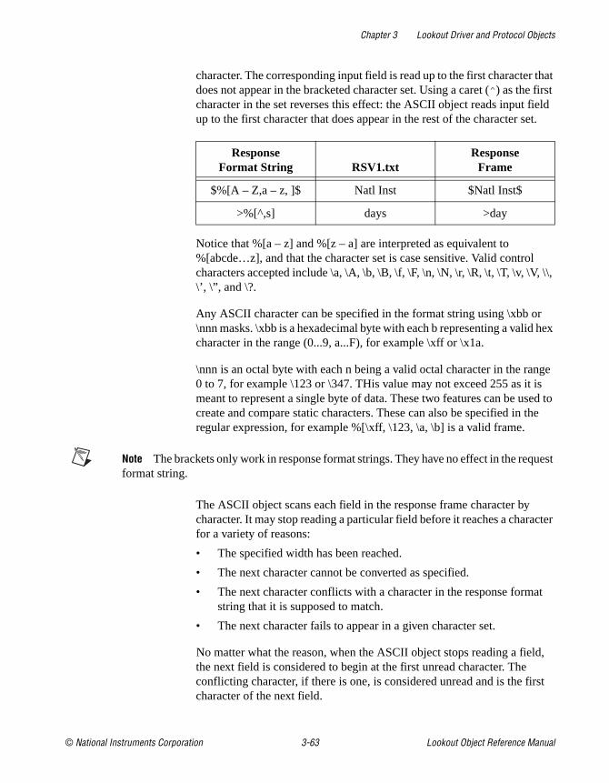
Chapter 3 Lookout Driver and Protocol Objects
© National Instruments Corporation 3-63 Lookout Object Reference Manual
character. The corresponding input field is read up to the first character that does not appear in the bracketed character set. Using a caret (^ ) as the first character in the set reverses this effect: the ASCII object reads input field up to the first character that does appear in the rest of the character set.
Notice that %[a – z] and %[z – a] are interpreted as equivalent to %[abcde…z], and that the character set is case sensitive. Valid control characters accepted include \a, \A, \b, \B, \f, \F, \n, \N, \r, \R, \t, \T, \v, \V, \\, \’, \”, and \?.
Any ASCII character can be specified in the format string using \xbb or \nnn masks. \xbb is a hexadecimal byte with each b representing a valid hex character in the range (0...9, a...F), for example \xff or \x1a.
\nnn is an octal byte with each n being a valid octal character in the range 0 to 7, for example \123 or \347. THis value may not exceed 255 as it is meant to represent a single byte of data. These two features can be used to create and compare static characters. These can also be specified in the regular expression, for example %[\xff, \123, \a, \b] is a valid frame.
Note The brackets only work in response format strings. They have no effect in the request format string.
The ASCII object scans each field in the response frame character by character. It may stop reading a particular field before it reaches a character for a variety of reasons:
• The specified width has been reached.
• The next character cannot be converted as specified.
• The next character conflicts with a character in the response format string that it is supposed to match.
• The next character fails to appear in a given character set.
No matter what the reason, when the ASCII object stops reading a field, the next field is considered to begin at the first unread character. The conflicting character, if there is one, is considered unread and is the first character of the next field.
ResponseFormat String RSV1.txt
ResponseFrame
$%[A – Z,a – z, ]$ Natl Inst $Natl Inst$
>%[^,s] days >day
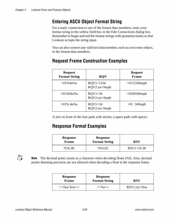
Chapter 3 Lookout Driver and Protocol Objects
Lookout Object Reference Manual 3-64 www.natinst.com
Entering ASCII Object Format StringFor a static connection to one of the format data members, enter your format string in the yellow field box in the Edit Connections dialog box. Remember to begin and end the format strings with quotation marks so that Lookout accepts the string input.
You can also connect any valid text data member, such as a text entry object, to the format data members.
Request Frame Construction Examples
A zero in front of the four pads with zeroes; a space pads with spaces.
Response Format Examples
Note The decimal point counts as a character when decoding floats (%f). Also, decimal points denoting precision are not allowed when decoding a float in the response frame.
RequestFormat String RQV
RequestFrame
<01%4u%s RQV1=1234 RQV2.txt=Steph
<011234Steph
<01%04u%s RQV1=34 RQV2.txt=Steph
<010034Steph
<01% 4u%s RQV1=34 RQV2.txt=Steph
<01 34Steph
ResponseFrame
ResponseFormat String RSV
*(16.38: *(%52f: RSV1=16.38
ResponseFrame
ResponseFormat String RSV
>>Test Text<< >>%s<< RSV1.txt=Test

Chapter 3 Lookout Driver and Protocol Objects
© National Instruments Corporation 3-65 Lookout Object Reference Manual
The space between the words terminates the conversion. See the preceding bracketed character example in order to span a space or other special characters.
The response format uses a space as a delimiter.
Using Sum Data MembersThe ASCII object includes summing data members you can use to calculate checksum characters. This can be a checksum you want to write into an outgoing request frame or a checksum you want to verify in an incoming response frame.
For example, if you want to calculate a checksum for the request A00B, you would use an RQSum (request sum) data member. In the case of A00B, you would use RQSum1:4, which would give you a sum of the ASCII byte values of characters 1 through 4. Once you have this sum, you can manipulate it mathematically any way necessary for the checksum value you need. You can then insert this value at the end of your frame as a byte (%b) or a series of bytes.
The same technique works in reverse for RSSum (response sum) data members.
For example, consider the response Z00A@. You know that you are expecting 4 bytes plus a checksum. Assuming that this checksum calculation involves the first four characters, use RSSum1:4 to get the byte sum of characters 1 through 4. After performing the appropriate mathematical manipulation, you can compare this value with the actual byte read from the frame, and determine when there is a checksum failure.
Note There are many different methods for calculating checksums, and these data members cannot support all of them. Before attempting to use them for checksum calculation, make sure your checksum can be calculated from a simple byte sum of characters in the frame.
ResponseFrame
ResponseFormat String RSV
>>Test Text<< >>%s%s<< RSV1.txt=TestRSV2.txt=Text
>>DogCat<< >>%3s%3s<< RSV1.txt=DogRSV2.txt=Cat

Chapter 3 Lookout Driver and Protocol Objects
Lookout Object Reference Manual 3-66 www.natinst.com
ASCII Error MessagesNo response from device within timeout period
Lookout received no response from the device within the Receive timeout period. The ASCII object was able to establish a socket, but when it sent a message to the device, the device did not respond—as if it were not there. You may have to significantly increase Receive timeout (and Poll Rate) to ensure Lookout is allowing enough time to receive the expected response. Also, verify your cable connections, power, configuration settings, and IP settings.
Not enough data to send a valid frame
This means that the ASCII object has not received enough data to fill in all the variables in the Request Format frame. This could mean that you do not have connections made to all of the RQVs that the ASCII object is expecting.
Frame Error (garbled)
ASCII got a response frame, but static characters in the response did not match up to the response format string.
Data type or length does not match format string
ASCII got a response frame, but certain characters in the response were not in the format stated by the markers in the response format string.
Illegal control character
The request frame had a % modifier followed by an invalid control code.
Related Objects IPASCII

Chapter 3 Lookout Driver and Protocol Objects
© National Instruments Corporation 3-67 Lookout Object Reference Manual
Cutler-HammerCutler-Hammer is a protocol driver class Lookout uses to communicate with Cutler-Hammer devices using serial communications.
It supports reading and writing of all predefined data points allowed by the particular Cutler-Hammer model. When you create a Cutler-Hammer object, you have immediate access to all the object data members. See the Cutler-Hammer Data Member Set table for more information on data members for this object.
Figure 3-10. Cutler-Hammer Definition Parameters Dialog Box
Address specifies which Cutler-Hammer device you are communicating with using this object. This number is between 0 and 191, and is set on the device. (An address number of 255 broadcasts to all devices connected to the network.)
PLC Model specifies what model of Cutler-Hammer device you are using. The only model supported now is the Cutler-Hammer D50.
Serial port specifies which comm port the object uses for communicating to the external device. This does not specify the communication type. Communication type is determined by the Options»Serial Ports command.

Chapter 3 Lookout Driver and Protocol Objects
Lookout Object Reference Manual 3-68 www.natinst.com
Note For Lookout to communicate correctly with the Cutler-Hammer D50, you must configure your COM port as radio using the Options»Serial Ports command.
Data rate indicates the baud rate that Lookout uses to communicate with the hardware device. This setting should match the selection made on the physical device.
Data bits indicates the number of data bits that Lookout uses to communicate with the hardware device. This setting should match the selection made on the physical device.
Stop bits indicates the number of stop bits that Lookout uses to communicate with the hardware device. This setting should match the selection made on the physical device.
Parity indicates the parity that Lookout uses to communicate with the hardware device. This setting should match the selection made on the physical device.
Phone number specifies the number to be dialed if the selected serial port is configured for dial-up. This number only applies to the individual protocol object.
PollRate is a numeric expression that determines how often to poll the device. Lookout converts the numeric value of PollRate into a time signal that represents days and fractions of a day. The object then polls the device at the specified time interval. Normally, this is a time constant such as 0:01 (one second). See the Numeric Data Members section in Chapter 2, How Lookout Works, of the Getting Started with Lookout manual for information on entering time constants.
Poll is a logical expression. When this expression changes from false to true, Lookout polls the device. You can use a simple expression like the signal from a pushbutton, or a complex algorithm.
Communication alarm priority determines the priority level of alarms generated by the Cutler-Hammer object. Such alarms are typically related to communications with the physical device.
Retry attempts specifies the consecutive number of times Lookout attempts to establish communications with a device if it is not getting a valid response. After it tries the number of Retry attempts specified, the Cutler-Hammer object generates an alarm and releases the comm port. See Chapter 3, Serial Communications, in the Lookout Developer’s Manual for more information.

Chapter 3 Lookout Driver and Protocol Objects
© National Instruments Corporation 3-69 Lookout Object Reference Manual
Receive timeout is the time delay Lookout uses in waiting for a response from a device before retrying the request.
The Skip every N poll requests after comm failure setting instructs Lookout to not poll a device it has lost communication with on every scheduled poll. Instead, Lookout skips the device in the polling cycle accordingly. Once communications have been reestablished, the device is polled on its regular cycle.
Cutler-Hammer Data MembersAs with all Lookout drivers, you can access I/O points and other data through data members. The following is a table of data members currently supported by the Cutler-Hammer object class.
Table 3-25. Cutler-Hammer Data Member Set
Data Member Type Read Write Description
CommFail logical yes no Goes high if Lookout cannot communicate with the device
K0000 - K0015 numeric yes yes Keep relay
K00000.logical - K01515.logical
logical yes yes Keep relay
M0000 - M0031 numeric yes yes Internal relay
M00000.logical - M03115.logical
logical yes yes Internal relay
Poll logical no yes When transitioned from low to high, Lookout begins a poll cycle on the device
PollRate numeric no yes Specifies the frequency at which Lookout polls the device
R00000.logical - R02915.logical
logical yes yes External inputs and outputs, and special function registers

Chapter 3 Lookout Driver and Protocol Objects
Lookout Object Reference Manual 3-70 www.natinst.com
Cutler-Hammer Status MessagesNo response within timeout period
Lookout received no response from a device within the Receive timeout period. The Cutler-Hammer object is able to use the comm port, but when it polls the device, it does not respond—as if it is not even there. If you have daisy-chained several devices, you may have introduced an inherent delay. You may have to significantly increase Receive timeout (and Poll Rate) to ensure Lookout is allowing enough time to receive the expected response. This increase has nothing to do with the processing capabilities of Lookout. Rather it is based solely on Data rate and the number of devices on the chain. Also, verify your baud rate settings, cable connections, power, configuration settings, comm port settings, and polling addresses.
Invalid query acknowledge frame
This means that the query acknowledge frame sent from the PLC in response to the command sent by Lookout out was invalid.
Invalid PLC address in response frame
This means that the address within the response frame from the PLC does not match exactly the address in the command sent out by Lookout. You may possibly be requesting an address that is outside the valid range from Cutler-Hammer devices.
Invalid CRC in response
This means the checksum (CRC in this case) failed in a frame received by Lookout. Check cabling or for two or more devices with the same address.
Garbled or invalid frame
Frame received without format characters in their proper positions. Check the Receive gap setting.
Update logical yes no Goes high when Lookout begins a poll cycle on the device
W0000 - W2815 numeric yes yes Timers, counters, and word registers
For a more complete definition of the function of these data members, see Cutler-Hammer documentation.
Not all of these data members are valid for every Cutler-Hammer device. See Cutler-Hammer documentation to see which data members are valid for your particular model number.
Table 3-25. Cutler-Hammer Data Member Set (Continued)
Data Member Type Read Write Description

Chapter 3 Lookout Driver and Protocol Objects
© National Instruments Corporation 3-71 Lookout Object Reference Manual
Invalid response frame
This means that the response frame from the PLC did not have the expected number of bytes in it.
Invalid function code in response frame
This means that the function code within the response frame from the PLC does not match the function code in the command sent out by Lookout.
Wrong query, length, or designation
This is an error returned as an error code frame from the Cutler-Hammer device. This means that the device could not successfully interpret the query you just sent it.
Designated range exceeded
This is an error returned as an error code frame from the Cutler-Hammer device. It means you have requested an address beyond the valid range of addresses.
Command too long in length
This is an error returned as an error code frame from the Cutler-Hammer device. This means that the frame just sent has exceeded the maximum amount information that can be transported in a single frame (256 bytes).
Abnormal communications command
This is an error returned as an error code frame from the Cutler-Hammer device.
Cutler-Hammer models supported:
D50
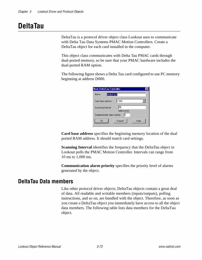
Chapter 3 Lookout Driver and Protocol Objects
Lookout Object Reference Manual 3-72 www.natinst.com
DeltaTauDeltaTau is a protocol driver object class Lookout uses to communicate with Delta Tau Data Systems PMAC Motion Controllers. Create a DeltaTau object for each card installed in the computer.
This object class communicates with Delta Tau PMAC cards through dual-ported memory, so be sure that your PMAC hardware includes the dual-ported RAM option.
The following figure shows a Delta Tau card configured to use PC memory beginning at address D000.
Card base address specifies the beginning memory location of the dual ported RAM address. It should match card settings.
Scanning Interval identifies the frequency that the DeltaTau object in Lookout polls the PMAC Motion Controller. Intervals can range from 10 ms to 1,000 ms.
Communication alarm priority specifies the priority level of alarms generated by the object.
DeltaTau Data membersLike other protocol driver objects, DeltaTau objects contain a great deal of data. All readable and writable members (inputs/outputs), polling instructions, and so on, are bundled with the object. Therefore, as soon as you create a DeltaTau object you immediately have access to all the object data members. The following table lists data members for the DeltaTau object.
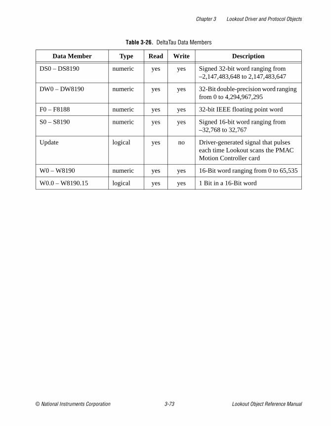
Chapter 3 Lookout Driver and Protocol Objects
© National Instruments Corporation 3-73 Lookout Object Reference Manual
Table 3-26. DeltaTau Data Members
Data Member Type Read Write Description
DS0 – DS8190 numeric yes yes Signed 32-bit word ranging from –2,147,483,648 to 2,147,483,647
DW0 – DW8190 numeric yes yes 32-Bit double-precision word ranging from 0 to 4,294,967,295
F0 – F8188 numeric yes yes 32-bit IEEE floating point word
S0 – S8190 numeric yes yes Signed 16-bit word ranging from –32,768 to 32,767
Update logical yes no Driver-generated signal that pulses each time Lookout scans the PMAC Motion Controller card
W0 – W8190 numeric yes yes 16-Bit word ranging from 0 to 65,535
W0.0 – W8190.15 logical yes yes 1 Bit in a 16-Bit word

Chapter 3 Lookout Driver and Protocol Objects
Lookout Object Reference Manual 3-74 www.natinst.com
DL205,DL405
DL205 and DL405 are protocol driver object classes Lookout uses to communicate with Koyo 205 and 405 PLCs, and other devices that use the CCM protocol.
Koyo sells the 205 and 405 models under private brand labels. PLCDirect offers the units as the DirectLOGIC 205 and 405 PLCs, and Siemens offers the 405 unit as the TI405 series.
The DL205 and DL405 object classes support the Koyos native protocol, CCM, which is also called DirectNET by PLCDirect and HostLink by Siemens. This documentation refers to this protocol as CCM.
The DL205 and DL405 object classes support both point-to-point and multidrop configurations. You can connect Lookout to a PLC programming port, built-in DirectNET/HostLink port, or to the PLC DCM (data communication module). These PLC communication ports use two different versions of the CCM protocol: K-sequence and N-sequence. Lookout supports both.
Figure 3-11. DL205 Parameters Configured for one PLC in a Multidropped Configuration

Chapter 3 Lookout Driver and Protocol Objects
© National Instruments Corporation 3-75 Lookout Object Reference Manual
Protocol identifies the CCM port you use to communicate with the device. If you are planning to connect Lookout to a single PLC in a point-to-point configuration, choose the UPPER PORT (k) Protocol and use the PLC programming port. It supports K-sequence CCM. With this version of the CCM protocol you can write directly to logical outputs.
If you are planning to network multiple PLCs in a multidrop configuration where Lookout is the host computer, you must use the built-in PLC DirectNET/HostLink port, or its DCM. Choose the LOWER PORT (n) or DCM (n) Protocol as appropriate. These ports support N-sequence CCM. The N-sequence CCM protocol does not permit writes directly to logical data members.
Note Although you can connect logical signals to data members such as Y0 in Lookout, any time you attempt to write to such a data member using the N-sequence CCM protocol, the write request is ignored. (This is due to the limitations of N-sequence CCM protocol.) If you have to write out a logical value using N-sequence, consider parsing the corresponding VU address into a binary number and setting the bit you want to use by writing a corresponding decimal integer. If you write a zero or 65535 to the corresponding VU-memory location, you will write all zeros or ones to every bit in the register.
PLC Address is a slave address and refers to the address setting as set on the physical device. If you are connecting to the PLC programming port, set PLC Address to 1. If multiple devices share a common line, enter the unique addresses of the device (1 to 255).
Use Model to choose the PLC model you want to use. If you are using a model not listed, select a model whose data set most closely fits the model you are using.
Serial port specifies which COM port on your computer that the object uses for communicating to the PLC. This does not specify the communication type. Communication type is determined by the Options»Serial Ports… command.
Data rate, Parity, Data bits, and Stop bits should match the PLC settings.
Phone number specifies the number to be dialed if the selected serial port is configured for dial-up. This number only applies to the individual protocol object.
PollRate is a numeric expression that determines how often to poll the device. The object then polls the device at the specified time interval. Normally, this is a simple time constant such as 0:01 (one second).

Chapter 3 Lookout Driver and Protocol Objects
Lookout Object Reference Manual 3-76 www.natinst.com
SeeNumeric Data Members in Chapter 2, How Lookout Works, of the Getting Started with Lookout manual for information on entering time constants.
Poll is a logical expression. When this expression changes from false to true, Lookout polls the device. You can use a simple expression like the signal from a pushbutton, or a complex algorithm.
Communication alarm priority determines the priority level of alarms generated by the object. Such alarms are typically related to communications with the physical device.
Retry attempts specifies the consecutive number of times Lookout attempts to establish communications with a device it does not get a valid response from. After the object retries communications the specified number of times, it generates a communication alarm and Lookout moves on to the next device in the polling queue (if any). Refer to Chapter 3, Serial Communications, in the Lookout Developer’s Manual for more information.
Receive timeout is the time delay Lookout uses in waiting for a response from a device before retrying the request.
The Skip every… setting instructs Lookout to not poll a device it has lost communication with on every scheduled poll. Instead, Lookout skips the device in the polling cycle accordingly. Once communications have been reestablished, the device is polled on its regular cycle.
DL205 and DL405 Data MembersProtocol driver objects contain a great deal of data. V-memory addresses, registers, inputs and outputs are all bundled with the object. Therefore, as soon as you create a DL205 object you have immediate access to the entire data member set of the object (see data member list in Table 3-27).
As with all Lookout drivers, you can access I/O points and other data through data members. The DL205 and DL405 object classes automatically generate an efficient read/write blocking scheme based on the inputs and outputs you are using in your process file. So, you do not have to build your own I/O blocking table. When Lookout polls a device, it optimizes frame exchange according to the data length required and overhead needed. The maximum data frame size that these drivers request is 256 data bytes. The drivers use LRC and parity error checking to validate data.

Chapter 3 Lookout Driver and Protocol Objects
© National Instruments Corporation 3-77 Lookout Object Reference Manual
The following is a table of data members currently supported by the DL205 and DL405 object class.
Table 3-27. DL205 and DL405 Data Members
Data Member Type Read Write Description
C0 – C3777 logical yes yes Control Relays—addressed in octal and mapped to V40600 – V40700.
CommFail logical yes no Object-generated signal that is on if, for whatever reason, Lookout cannot communicate with the device.
CT0 – CT377 logical yes yes Counter status bits—addressed in octal and mapped to V41140 – V41147.
OffHook logical no yes When TRUE, this flag instructs the DL object to retain exclusive use of its assigned communication port.
Poll logical no yes When this value transitions from FALSE to TRUE, Lookout polls the device.
PollRate numeric no yes Lookout expression that determines the device polling frequency.
S0 – S1777 logical yes yes Stages—addressed in octal and mapped to V41000 – V41037.
SPA0 – SPA177 logical yes yes Lower special relays—addressed in octal.
SPB320 – SPB717 logical yes yes Upper special relays—addressed in octal.
T0 – T377 logical yes yes Timer status bits—addressed in octal and mapped to V41100 – V41107.
Update logical yes no Object-generated signal that pulses low each time it polls the device.
V0 – V41230 numeric yes yes Signed V-memory register containing 16-bit integer ranging from –32768 to 32767 dec.

Chapter 3 Lookout Driver and Protocol Objects
Lookout Object Reference Manual 3-78 www.natinst.com
DL205 and DL405 Status MessagesNo response within timeout period
Lookout did not receive the expected response within the Receive timeout period. The object sent an inquiry and received an acknowledgment, but the device did not send an expected response to the request. This might happen if the response was interrupted. You may have to increase Receive timeout.
No return inquiry response from secondary unit
Lookout received no response from the device within the Receive timeout period. The driver object is able to use the COM port, but when it polls
V0.0 – V41230.17 logical yes no Individual bits within V-memory registers—the least significant bit is 0, the most significant bit is 17 (octal).
VBCD0-VBDC41230 numeric yes yes V-memory as BCD.
VD0 – VD41227 numeric yes yes Double—reads two adjacent V-memory registers as a single 32-bit integer ranging from 0 to 4,294,967,296.
VDBCD0-VDBCD41227
numeric yes yes V-memory double as BCD.
VF0 – VF41227 numeric yes yes Float—reads two adjacent V-memory registers as a single 32-bit floating point value.
VU0 – VU41230 numeric yes yes Unsigned—V-memory register holding 16-bit unsigned integer ranging from 0 to 65535.
X0 – X1777* logical yes yes Discrete input points—addressed in octal and mapped to V40400 – V40407.
Y0 – Y1777* logical yes yes Discrete output points—addressed in octal and mapped to V40500 – V40507.
* 205 series PLCs are limited to 128 input and output points total. You can mix these addresses as necessary, but understand that Y17 and X17 refer to the same memory location on DL205.
Table 3-27. DL205 and DL405 Data Members (Continued)
Data Member Type Read Write Description

Chapter 3 Lookout Driver and Protocol Objects
© National Instruments Corporation 3-79 Lookout Object Reference Manual
the device, it does not respond—as if it is not even there. You may have to increase Receive timeout to ensure Lookout is allowing enough time to receive the expected response. Also, verify your baud rate settings, cable connections, power, configuration settings, COM port settings, and polling addresses.
Bad LRC
The object is receiving a poll response from the device, but it could not decipher the response because it is garbled. Verify that all devices connected to the COM port have unique addresses. The last part of the message may actually be getting clipped off before it is completed. Consider increasing the number of Retry attempts. You may have to increase the Receive gap Serial Port setting to ensure Lookout is receiving the entire message. If your Serial Port is configured for radio, this could be caused by an audible squelch tail occurring at the end of a radio transmission. Try adjusting RTS delay off and CTS timeout.
No acknowledgment for header frame
You sent an inquiry and some kind of data write or read, but the device has not responded. The object was expecting an acknowledgment for an instruction frame and did not receive it. You may be asking for an invalid memory address. Recheck your PLC memory address configuration. Also verify that the PLC communication port supports the CCM Protocol that you selected.
Invalid request frame
You are probably trying to use an invalid memory address. Recheck your PLC address configuration.

Chapter 3 Lookout Driver and Protocol Objects
Lookout Object Reference Manual 3-80 www.natinst.com
DNP
Use the DNP driver to connect to specific devices using the Distributed Network Protocol version 3.0.
Address specifies which device you are communicating with using this object. This number is between 0 and 255, and is set on the device.
Source Address specifies the DNP address of the computer running Lookout.
Serial port specifies which port the object uses for communication to the external device. This does not specify the communication type. You set communication type in the Serial Ports dialog box. Select Options»Serial Ports to access this dialog box.
Baud Rate, Parity, Data bits, and Stop bits reference the settings on the hardware device.
Phone number specifies the number to be dialed if the serial port setting is configured for dial-up. This number only applies to the individual protocol object.
PollRate is a numeric expression that determines how often to poll your DNP device. The object then polls the device at the specified time interval. Normally, this is a simple time constant such as 0:01 (one second).

Chapter 3 Lookout Driver and Protocol Objects
© National Instruments Corporation 3-81 Lookout Object Reference Manual
SeeNumeric Data Members in Chapter 2, How Lookout Works, of the Getting Started with Lookout manual for more information.
Poll is a logical expression. When this expression changes from FALSE to TRUE, Lookout polls your DNP device for data from the specified device. You can use a simple expression like the signal from a pushbutton, or a complex algorithm.
The Skip N poll requests after COM failure setting instructs Lookout to not poll a device it has lost communication with on every scheduled poll. Instead, Lookout skips the device in the polling cycle. Once communications have been reestablished, the device is polled on its regular cycle.
Retry attempts specifies the consecutive number of times Lookout attempts to establish communications with a device if it is not getting a valid response. After it tries the number of Retry attempts specified, the DNP object generates an alarm and releases the communication port back to the communications service which then moves on to the next device in the polling queue (if any).
Receive timeout is the time delay Lookout uses in waiting for a response from a device before retrying the request.
Communication alarm priority determines the priority level of alarms generated by the object. Such alarms are typically related to communications with the physical device.
DNP Data Members
Table 3-28. DNP Data Members
Data Member Type Read Write Description
AINDW0-AINDW65535
numeric yes no 32-bit analog input(object 30, variation 3)
AINFDW0-AINFDW65535
numeric yes no 32-bit analog input with flag(object 30, variation 1)
AINFW0-AINFW65535 numeric yes no 16-bit analog input with flag(object 30, variation 2)
AINW0-AINW65535 numeric yes no 16-bit analog input(object 30, variation 4)

Chapter 3 Lookout Driver and Protocol Objects
Lookout Object Reference Manual 3-82 www.natinst.com
AOUTFDW0-AOUTFDW65535
numeric yes yes 32-bit analog output with flag (object 40, variation 1)
AOUTFW0-AOUTFW65535
numeric yes yes 16-bit analog output with flag (object 40, variation 2)
BIN0-BIN65535 logical yes no Binary input (object 1, variation 1)
BINS0-BINS65535 logical yes no Binary input with status (object 1, variation 2)
BOUT0-BOUT65535 logical yes yes Binary output (object 10, variation 1)
BOUTS0-BOUTS65535 logical yes yes Binary output with status (object 10, variation 2)
CNTDW0-CNTDW65535
numeric yes no 32-bit counter (object 20, variation 5)
CNTFDW0-CNTFDW65535
numeric yes no 32-bit counter with flag (object 20, variation 1)
CNTFW0-CNTFW65535
numeric yes no 16-bit counter with flag (object 20, variation 2)
CNTW0-CNTW65535 numeric yes no 16-bit counter (object 20, variation 6)
CommFail logical yes no Object-generated signal that is on if, for whatever reason, Lookout cannot communicate with your DNP device.
DCNTDW0-DCNTDW65535
numeric yes no 32-bit delta counter (object 20, variation 7)
DCNTFDW0-DCNTFDW65535
numeric yes no 32-bit delta counter with flag (object 20, variation 3)
DCNTFW0-DCNTFW65535
numeric yes no 16-bit delta counter with flag (object 20, variation 4)
DCNTW0-DCNTW65535
numeric yes no 16-bit delta counter (object 20, variation 8)
FL0-FL65535 numeric yes yes 64-bit float (object 100, variation 2)
FS0-FS65535 numeric yes yes 32-bit float (object 100, variation 1)
Table 3-28. DNP Data Members (Continued)
Data Member Type Read Write Description

Chapter 3 Lookout Driver and Protocol Objects
© National Instruments Corporation 3-83 Lookout Object Reference Manual
Error MessagesNo response within timeout period
Lookout received no response from a device within the Receive timeout period. The DNP object is able to use the COM port, but when it polls the device, it doesn’t respond—as if it is not there. If you have daisy-chained several devices, you have introduced an inherent delay. You may have to significantly increase Receive timeout (and Poll Rate) to ensure Lookout is allowing enough time to receive the expected response. This increase has nothing to do with the processing capabilities of Lookout. It is based solely on Baud rate and the number of devices on the chain. Also, verify your baud rate settings, cable connections, power, configuration settings, COM port settings, and polling addresses.
FT3 Error: No start bytes
The driver could not find the bytes that signify the beginning of a DNP frame in a response received from the device. This kind of garbled frame might be caused by bad communications settings.
FT3 Error: FCB fail
The Frame Count Bit (FCB) in the received frame was wrong. This bit helps to ensure that messages are sent and received in the right order. If you are consistently seeing this error you may have a lot of quiescent traffic on the network that is disrupting the driver.
FT3 Error: Bad destination byte
The DNP driver received a message that was not addressed to it.
Poll logical no yes When this value transitions from FALSE to TRUE, Lookout polls the device.
PollRate numeric no yes Lookout expression that determines the device polling frequency.
TIMEDATE numeric yes no Device time and date (in Lookout time format) (object 50, variation 1)
Update logical yes no Object-generated signal that pulses low each time it polls the device.
Table 3-28. DNP Data Members (Continued)
Data Member Type Read Write Description

Chapter 3 Lookout Driver and Protocol Objects
Lookout Object Reference Manual 3-84 www.natinst.com
FT3 Error: Bad source bytes
The DNP driver received a message that was not from the device that this object is monitoring.
FT3 Error: CRC fail
One of the FT3 level checksums failed. If this happens consistently, verify your communications link and settings.
FT3 Error: Bad transport header sequence number
The sequence number in the transport header in the received frame was wrong. This number helps to ensure that messages are sent and received in the right order. If you are consistently seeing this error you may have a lot of quiescent traffic on the network that is disrupting the driver.
FT3 Error: Bad application control sequence number
The sequence number in the application control byte in the received frame was wrong. This number helps to ensure that messages are sent and received in the right order. If you are consistently seeing this error you may have a lot of quiescent traffic on the network that is disrupting the driver.
FT3 Error: Bad DIR
The DIR bit identifies a message as from the master or from a slave. If you get this error you may have multiple masters set up on your network.
FT3 Error: Bad PRM
The PRM bit identifies a message as from an initiating station or from a secondary station. If you get this error you may have multiple masters set up on your network.

Chapter 3 Lookout Driver and Protocol Objects
© National Instruments Corporation 3-85 Lookout Object Reference Manual
DynamicDynamic is a protocol driver class Lookout uses to communicate with equipment such as programmable logic controllers (PLCs), remote terminal units (RTUs), or any other piece of equipment that uses Dynamic as its communication protocol.
Protocol driver objects contain a great deal of data. All readable and writable members (inputs/outputs), polling instructions, read/write blocking, serial port usage, etc. are bundled with the object. Therefore, as soon as you create a Dynamic object you immediately have access to all the object data members (see data member list in this section).
The driver currently supports reading and writing of all predefined data point types including analog input, state input, pulse count input, pulse duration input, pulse period input, high speed accumulator inputs, state outputs, pulse outputs, analog outputs, and AGA data.
The driver automatically configures the RTU database to match the data points referenced in the Lookout process file and verifies that the points specified in the process file actually exist on the RTU. If you reference undefined or unavailable points, the driver posts an alarm message to the Lookout alarm system.
The Dynamic protocol driver automatically takes advantage of the RTU exception reporting capabilities to maximize communication efficiency. The driver requires that the RTU be set for physical point addressing—refer to the RTU hardware technical reference manual for the dipswitch locations that set this parameter.
Note Lookout protocol driver objects automatically generate an efficient read/write blocking scheme based on the inputs and outputs being used in your process file. You are not required to build your own I/O blocking table.
The Dynamic protocol driver was written for Texas Instruments Model 8635, 8640 and 8641 RTUs (Remote Terminal Units) with RTX 5.41 EPROMs—earlier releases of RTX have significant bugs and do not operate correctly with the Lookout Dynamic driver.
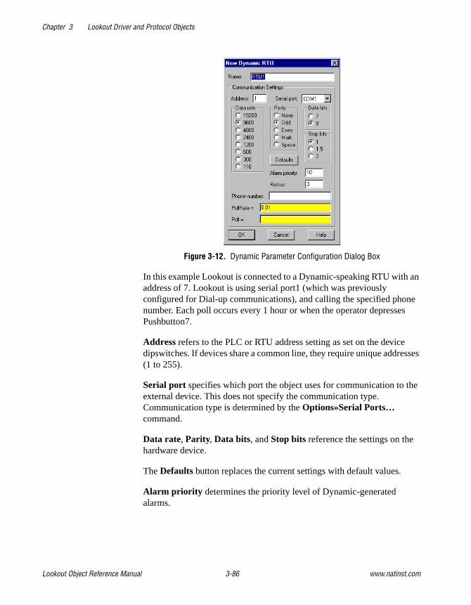
Chapter 3 Lookout Driver and Protocol Objects
Lookout Object Reference Manual 3-86 www.natinst.com
Figure 3-12. Dynamic Parameter Configuration Dialog Box
In this example Lookout is connected to a Dynamic-speaking RTU with an address of 7. Lookout is using serial port1 (which was previously configured for Dial-up communications), and calling the specified phone number. Each poll occurs every 1 hour or when the operator depresses Pushbutton7.
Address refers to the PLC or RTU address setting as set on the device dipswitches. If devices share a common line, they require unique addresses (1 to 255).
Serial port specifies which port the object uses for communication to the external device. This does not specify the communication type. Communication type is determined by the Options»Serial Ports… command.
Data rate, Parity, Data bits, and Stop bits reference the settings on the hardware device.
The Defaults button replaces the current settings with default values.
Alarm priority determines the priority level of Dynamic-generated alarms.

Chapter 3 Lookout Driver and Protocol Objects
© National Instruments Corporation 3-87 Lookout Object Reference Manual
Phone number specifies the number to be dialed if the serial port setting is configured for dial-up. This number only applies to the individual protocol object.
PollRate is a numeric expression that determines how often to poll the device. Dynamic then polls the device at the specified time interval. Normally, this is a simple time constant such as 0:01 (one second). See Numeric Data Members in Chapter 2, How Lookout Works, of the Getting Started with Lookout manual for information on entering time constants.
Poll is a logical expression. When this expression changes from false to true, Lookout polls the device. You can use a simple expression like the signal from a pushbutton, or a complex algorithm.
As with all Lookout drivers, you can access I/O points and other data through data members. The following is a table of data members currently supported by the Dynamic object class.
Dynamic Data Members
Table 3-29. Dynamic Data Members
Data Members Type Read Write Description
AI0 – AI239 numeric yes no Analog inputs—returns a normalized numeric value that ranges from 0 to 32000 and spans the full input analog range.
AO0 – AO239 numeric no yes Analog outputs—sets voltage level of analog outputs, and accepts a normalized number from 0 to 32000.
btu1 – btu4 numeric yes no AGA data
dp1 – dp4 numeric yes no Differential pressure (psi). 1 – 4 specifies meter run being referenced.
HSA0 – HSA127 numeric yes no High-speed accumulator inputs—counts the number of digital pulses on an HSA input. Rollover is detected automatically by driver, so maximum pulse count is 4.5 × 10¹⁵.
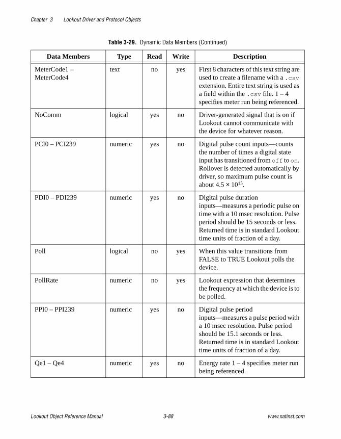
Chapter 3 Lookout Driver and Protocol Objects
Lookout Object Reference Manual 3-88 www.natinst.com
MeterCode1 – MeterCode4
text no yes First 8 characters of this text string are used to create a filename with a .csv extension. Entire text string is used as a field within the .csv file. 1 – 4 specifies meter run being referenced.
NoComm logical yes no Driver-generated signal that is on if Lookout cannot communicate with the device for whatever reason.
PCI0 – PCI239 numeric yes no Digital pulse count inputs—counts the number of times a digital state input has transitioned from off to on. Rollover is detected automatically by driver, so maximum pulse count is about 4.5 × 10¹⁵.
PDI0 – PDI239 numeric yes no Digital pulse duration inputs—measures a periodic pulse on time with a 10 msec resolution. Pulse period should be 15 seconds or less. Returned time is in standard Lookout time units of fraction of a day.
Poll logical no yes When this value transitions from FALSE to TRUE Lookout polls the device.
PollRate numeric no yes Lookout expression that determines the frequency at which the device is to be polled.
PPI0 – PPI239 numeric yes no Digital pulse period inputs—measures a pulse period with a 10 msec resolution. Pulse period should be 15.1 seconds or less. Returned time is in standard Lookout time units of fraction of a day.
Qe1 – Qe4 numeric yes no Energy rate 1 – 4 specifies meter run being referenced.
Table 3-29. Dynamic Data Members (Continued)
Data Members Type Read Write Description

Chapter 3 Lookout Driver and Protocol Objects
© National Instruments Corporation 3-89 Lookout Object Reference Manual
Qsum1 – Qsum4 numeric yes no Accumulated flow over the last 60 minutes (cubic feet – CF). 1 – 4 specifies meter run being referenced.
Qsum_month1 – Qsum_month4
numeric yes no Accumulated flow over the last 30 days (cubic feet – CF). 1 – 4 specifies meter run being referenced.
Qsum_yesterday1– Qsum_yesterday4
numeric yes no Accumulated flow over the last 24 hours (cubic feet – CF). 1 – 4 specifies meter run being referenced.
Qv1 – Qv4 numeric yes no Instantaneous flow rate (cubic feet/hour – CFH). 1 – 4 specifies meter run being referenced.
ReadHistory logical no yes When this value transitions from TRUE to FALSE, Lookout polls the device and reads the historical AGA from the RTU, storing to disk.
SI0 – SI239 logical yes no Digital state inputs
SO0 – SO239 logical no yes Digital state outputs. On the 8635, state outputs and pulse outputs are mapped to programmable I/O (PIO) points and range from SO8 to SO15.
sp1 – sp4 numeric yes no Static pressure (psi). 1 – 4 specifies meter run being referenced.
tf1 – tf4 numeric yes no Flowing temperature (deg. F). 1 – 4 specifies meter run being referenced.
Update logical yes no Driver-generated signal that pulses each time the driver polls the device
VB0-VB65535 logical yes yes Bit in V register read as logical.
VF0-VF2047 numeric yes yes V register read as float on 4-byte boundary.
VFN0-VFN2047 numeric yes yes V register read as float, no boundary.
Table 3-29. Dynamic Data Members (Continued)
Data Members Type Read Write Description
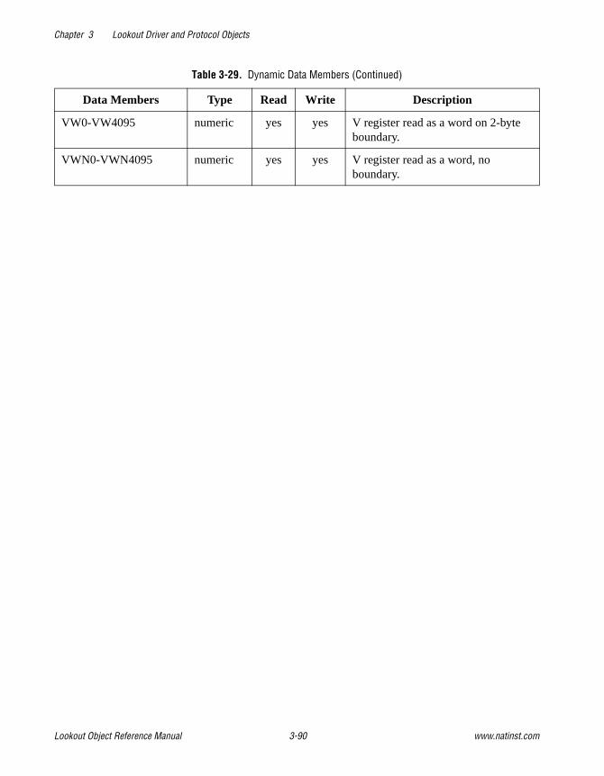
Chapter 3 Lookout Driver and Protocol Objects
Lookout Object Reference Manual 3-90 www.natinst.com
VW0-VW4095 numeric yes yes V register read as a word on 2-byte boundary.
VWN0-VWN4095 numeric yes yes V register read as a word, no boundary.
Table 3-29. Dynamic Data Members (Continued)
Data Members Type Read Write Description

Chapter 3 Lookout Driver and Protocol Objects
© National Instruments Corporation 3-91 Lookout Object Reference Manual
FisherROCFisherROC is a protocol driver class Lookout uses to communicate with a ROC364 (Remote Operations Controller) made by Fisher Controls. To communicate with the ROC364, connect directly to its COM1 or COM2 port. Depending on the device configuration, these ports may be configured for RS-232, RS-422/485 or Bell 202 modem communications.
Create one FisherROC object for each ROC364. This object class contains a great deal of data. All point types including inputs, outputs, PID, AGA, Tank, and their configuration signals are bundled with the object. Therefore, as soon as you create a FisherROC object you immediately have access to the object data member set.
Figure 3-13. FisherROC Definition Parameters Dialog Box
Group is the group code to which the ROC station is assigned. This is typically set to 2, but is configurable through the GV101 Configuration software.
Address is the unit code (address setting) of the ROC station as defined using the GV101 Configuration software. If multiple ROCs are members of the same group, then they must have unique addresses (0 to 255). As the host station, the Lookout computer is assigned Group 0, Address 1.

Chapter 3 Lookout Driver and Protocol Objects
Lookout Object Reference Manual 3-92 www.natinst.com
Controller model identifies the type of Fisher remote operations controller that the object represents. This object class supports ROC364.
Serial port specifies which COM port on the host computer that Lookout object uses for communicating to the external device. This does not specify the communication type. Communication type is determined by the Options»Serial Ports… command.
Data rate, Parity, Data bits, and Stop bits reference the settings on the hardware device.
Phone number specifies the number to be dialed if the selected serial port is configured for dial-up. This number only applies to the individual protocol object.
PollRate is a numeric expression that determines how often to poll the device. The object then polls the device at the specified time interval. Normally, this is a simple time constant such as 0:01 (one second). See Numeric Data Members in Chapter 2, How Lookout Works, of the Getting Started with Lookout manual for information on entering time constants.
Poll is a logical expression. When this expression changes from FALSE to TRUE, Lookout polls the device. You can use a simple expression like the signal from a pushbutton, or a complex algorithm.
Communication alarm priority determines the priority level of alarms generated by the object. Such alarms are typically related to communications with the physical device.
Retry attempts specifies the consecutive number of times Lookout attempts to establish communications with a device if it is not getting a valid response. After it tries the number of Retry attempts specified, the object generates an alarm and releases the communication port back to the communications service which then moves on to the next device in the polling queue (if any). Refer to Chapter 3, Serial Communications, in the Lookout Developer’s Manual for more information.
Receive timeout is the time delay Lookout uses in waiting for a response from a device before retrying the request.
The Skip every… setting instructs Lookout to not poll a device it has lost communication with on every scheduled poll. Instead, Lookout skips the device in the polling cycle accordingly. Once communications have been reestablished, the device is polled on its regular cycle.

Chapter 3 Lookout Driver and Protocol Objects
© National Instruments Corporation 3-93 Lookout Object Reference Manual
FisherROC Data Members
Table 3-30. FisherROC Data Members
Data Member Type Read Write Description
AGA1.la – AGA5.la numeric yes yes AGA low alarm EU value
AGF1.btud – AGF5.btud numeric yes no AGA Flow in units of MMBTU/Day
AGF1.btut – AGF5.btut numeric yes no MMBTUs of AGA Flow today
AGF1.btuy – AGF5.btuy numeric yes no MMBTUs of AGA Flow yesterday
AGF1.mcfd – AGF5.mcfd numeric yes no AGA Flow in units of MCF/Day
AGF1.mcft – AGF5.mcft numeric yes no MCFs of AGA Flow today
AGF1.mcfy – AGF5.mcfy numeric yes no MCFs of AGA Flow yesterday
AI:A1.adh – AI:D16.adh numeric yes yes Analog input adjusted A/D 100%
AI:A1.adl – AI:D16.adl numeric yes yes Analog input adjusted A/D 0%
AI:A1.dla – AI:D16.dla numeric yes yes Analog input Delta Alarm EU
AI:A1.euh – AI:D16.euh numeric yes yes Analog input High Reading EU
AI:A1.eul – AI:D16.eul numeric yes yes Analog input Low Reading EU
AI:A1.feu – AI:D16.feu numeric yes yes Analog input Filtered EU value
AI:A1.flt – AI:D16.flt numeric yes yes Analog input Filter
AI:A1.ha – AI:D16.ha numeric yes yes Analog input High alarm limit
AI:A1.hha – AI:D16.hha numeric yes yes Analog input High-High alarm limit
AI:A1.la – AI:D16.la numeric yes yes Analog input Low alarm limit
AI:A1.lla – AI:D16.lla numeric yes yes Analog input Low-Low alarm limit
AI:A1.raw – AI:D16.raw numeric yes no Analog input Raw A/D input value
AO:A1.adh – AO:D16.adh numeric yes yes Analog output Adjusted A/D 100%
AO:A1.adl – AO:D16.adl numeric yes yes Analog output Adjusted A/D 0%
AO:A1.eu – AO:D16.eu numeric yes yes Analog output EU output value
AO:A1.euh – AO:D16.euh numeric yes yes Analog output High Reading EU
AO:A1.eul – AO:D16.eul numeric yes yes Analog output Low Reading EU

Chapter 3 Lookout Driver and Protocol Objects
Lookout Object Reference Manual 3-94 www.natinst.com
CommFail logical yes no Object-generated signal that is on if, for whatever reason, Lookout cannot communicate with the ROC
DI:A1.acc – DI:D16.acc numeric yes yes Discrete input accumulated value
DI:A1.flt – DI:D16.flt logical yes yes Discrete input filter
DI:A1.ha – DI:D16.ha numeric yes yes Discrete input high alarm
DI:A1.hha – DI:D16.hha numeric yes yes Discrete input high-high alarm
DI:A1.la – DI:D16.la numeric yes yes Discrete input low alarm
DI:A1.lla – DI:D16.lla numeric yes yes Discrete input low-low alarm
DI:A1.sts – DI:D16.sts logical yes no Discrete input status (value)
DO:A1.acc – DO:D16.acc numeric yes yes Discrete output accumulated value
DO:A1.cth – DO:D16.cth numeric yes yes Discrete output 100% count
DO:A1.ctl – DO:D16.ctl numeric yes yes Discrete output 0% count
DO:A1.ctm – DO:D16.ctm numeric yes yes Discrete output cycle time
DO:A1.eu – DO:D16.eu numeric yes yes Discrete output EU value
DO:A1.rdh – DO:D16.rdh numeric yes yes Discrete output high reading EU
DO:A1.rdl – DO:D16.rdl numeric yes yes Discrete output low reading EU
DO:A1.sts – DO:D16.sts logical yes yes Discrete output status (value)
DO:A1.to – DO:D16.to numeric yes yes Discrete output time on
FST1.rg1 – FST8.rg10 numeric yes yes Function seq. table register value
FST1.rrg – FST8.rrg numeric yes yes Function seq. table result register
FST1.tm1 – FST8.tm4 numeric yes yes Function seq. table timer value
PID1.eu – PID16.eu numeric yes yes PID output EU value
PID1.ost – PID16.ost numeric yes yes PID OVR sw setpoint
PID1.pst – PID16.pst numeric yes yes PID PRI sw setpoint
PID1.set – PID16.set numeric yes yes PID setpoint value
Table 3-30. FisherROC Data Members (Continued)
Data Member Type Read Write Description

Chapter 3 Lookout Driver and Protocol Objects
© National Instruments Corporation 3-95 Lookout Object Reference Manual
PL:A1.acc – PL:D16.acc numeric yes yes Pulse input accumulated value
PL:A1.crt – PL:D16.crt numeric yes no Pulse input current rate
PL:A1.dla – PL:D16.dla numeric yes yes Pulse input delta alarm EU
PL:A1.eu – PL:D16.eu numeric yes yes Pulse input value in engineering units
PL:A1.ha – PL:D16.ha numeric yes yes Pulse input high alarm EU value
PL:A1.hha – PL:D16.hha numeric yes yes Pulse input high-high alarm EU value
PL:A1.la – PL:D16.la numeric yes yes Pulse input low alarm EU value
PL:A1.lla – PL:D16.lla numeric yes yes Pulse input low-low alarm EU value
PL:A1.rpd – PL:D16.rpd numeric yes yes Pulse input rate period
Poll logical no yes When this value transitions from FALSE to TRUE, Lookout polls the device.
PollRate numeric no yes Lookout expression that determines the device polling frequency.
SPT1.d1 – SPT32.d20 numeric yes yes Soft point parameter data number
TNK1.cfl – TNK8.cfl numeric yes no Tank current fluid level
TNK1.dis – TNK8.dis numeric yes no Tank barrels discharged
TNK1.dla – TNK8.dla numeric yes yes Tank delta alarm EU
TNK1.lsl – TNK8.lsl numeric yes no Tank last scan level
TNK1.man – TNK8.man numeric yes yes Tank manual entry—barrels
TNK1.ttl – TNK8.ttl numeric yes no Tank total barrels hauled
TNK1.tvl – TNK8.tvl numeric yes no Today’s tank volume
TNK1.yvl – TNK8.yvl numeric yes no Yesterday’s tank volume
Update logical yes no Object-generated signal that pulses low each time it polls the device
Table 3-30. FisherROC Data Members (Continued)
Data Member Type Read Write Description

Chapter 3 Lookout Driver and Protocol Objects
Lookout Object Reference Manual 3-96 www.natinst.com
Comments To read the raw value of an analog input located at I/O module socket 9 on the third mounting rack, you would enter NAME.AI:C9.raw , where
FisherROC Status MessagesNo response within timeout period
Lookout received no response from the ROC device within the Receive timeout period. The driver object is able to use the COM port, but when it polls the device, it does not respond—as if it is not even there. You may have to increase Receive timeout to ensure Lookout is allowing enough time to receive the expected response. Also, verify your baud rate settings, cable connections, power, configuration settings, COM port settings, and polling addresses.
Message Garbled—Bad CRC
The object is receiving a poll response from the device, but it cannot decipher the response. Verify that all devices assigned to the device group have unique unit codes. The last part of the message may actually be getting clipped off before it is completed. Consider increasing the number of Retry attempts. You may have to increase the Receive gap Serial Port setting to ensure Lookout is receiving the entire message. If your Serial Port is configured for radio, this could be caused by an audible squelch tail occurring at the end of a radio transmission. Try adjusting RTS delay off and CTS timeout.
Unexpected data response length
The object is receiving a poll response from the device, but the response is too long. Verify that all devices connected to the COM port and assigned to the same device group have unique unit codes. Devices with identical addresses may be trying to respond at the same time. Also verify device protocol settings.
Response too short
The object is receiving data of a length that does not meet the minimum frame length requirements. Verify device protocol settings. You may have to increase Receive timeout.
AI:C9.rawSignal Type
Mounting Rack (A,B,C, or D)
Parameter
Socket Number (1-16)

Chapter 3 Lookout Driver and Protocol Objects
© National Instruments Corporation 3-97 Lookout Object Reference Manual
Return unit address incorrectReturn group address incorrect
The object sent a data write or data read request, but the ROC did not respond. You may be asking for an invalid memory address. Recheck your ROC address configuration.
Invalid module or point requested
You attempted a data type mismatch. For example, you may have tried to write or read an analog value to or from a rack I/O socket that has a discrete module installed, or visa versa. This is an addressing problem. Verify that the type of I/O at the desired socket matches the signal type of the address identified in the data member you are writing to.
Unexpected opcode in response: xx
The object is receiving a poll response from the device, but the response was not expected. This might happen if the object receives a poll response after the Receive timeout period expires. You may have to increase Receive timeout. Another possibility is that the ROC is attempting an unsolicited communication. The FisherROC object class currently does not support unsolicited report-by-exception.

Chapter 3 Lookout Driver and Protocol Objects
Lookout Object Reference Manual 3-98 www.natinst.com
GE_Series90GE_Series90 is a protocol driver class Lookout uses to communicate with GE Series 90-30 and GE Series 90-70 programmable logic controllers (PLCs) using SNPX, a Series Ninety Protocol.
Figure 3-14. GE_Series90 Definition Parameters Dialog Box
PLC Address is a slave address and refers to the PLC address setting as configured on the device. The address can be up to eight ASCII characters.
Model chooses either 90-30 or 90-70.
Interface selects the protocol. You can choose between SNPX and Ethernet.
Serial port specifies which port the object uses for communication to the external device. This does not specify the communication type. Communication type is determined by the Options»Serial Ports… command.
Data rate, Parity, Data bits, and Stop bits reference the settings on the hardware device.

Chapter 3 Lookout Driver and Protocol Objects
© National Instruments Corporation 3-99 Lookout Object Reference Manual
Phone number specifies the number to be dialed if the serial port setting is configured for dial-up. This number only applies to the individual protocol object.
PollRate is a numeric expression that determines how often to poll the device. GE_Series90 then polls the device at the specified time interval. Normally, this is a simple time constant such as 0:01 (one second). See Numeric Data Members in Chapter 2, How Lookout Works, of the Getting Started with Lookout manual for information on entering time constants.
Poll is a logical expression. When this expression changes from FALSE to TRUE, Lookout polls the device. You can use a simple expression like the signal from a pushbutton, or a complex algorithm.
Communication alarm priority determines the priority level of object-generated alarms (0 – 10).
Retry attempts specifies the consecutive number of times Lookout attempts to establish communications with a device if it is not getting a valid response. After it tries the number of Retry attempts specified, the GE_Series90 object generates an alarm and releases the communication port back to the communications service which then moves on to the next device in the polling queue (if any). Refer to Chapter 3, Serial Communications, in the Lookout Devleoper’s Manual for more information.
Receive timeout is the time delay Lookout uses in waiting for a response from a device before retrying the request.
The Skip every… setting instructs Lookout to not poll a device it has lost communication with on every scheduled poll. Instead, Lookout skips the device in the polling cycle accordingly. Once communications have been reestablished, the device is polled on its regular cycle.
GE_Series90 Data MembersThis protocol driver object contains a great deal of data. All readable and writable members (inputs/outputs), polling instructions, read/write blocking, serial port usage, and so on, are bundled with the object. Therefore, as soon as you create a GE_Series90 object you immediately have access to all the object data members (see data member list in Table 3-31).

Chapter 3 Lookout Driver and Protocol Objects
Lookout Object Reference Manual 3-100 www.natinst.com
Note Lookout protocol driver objects automatically generate an efficient read/write blocking scheme based on the inputs and outputs being used in your process file. You are not required to build your own I/O blocking table.
Table 3-31. GE_Series90 Data Members
Data Member Type Read Write Description
AI1 – AI64 numeric yes yes 16-bit analog inputs encoded as unsigned binary integers ranging from 0 to 65535
AID1 – AID64 numeric yes yes 32-bit analog inputs encoded as unsigned binary integers ranging from 0 to 65535
AQ1 – AQ64 numeric yes yes 16-bit analog outputs encoded as unsigned binary integers ranging from 0 to 65535
AQD1 – AQD64 numeric yes yes 32-bit analog outputs encoded as unsigned binary integers ranging from 0 to 65535
CommFail logical yes no Object-generated signal that is on if, for whatever reason, Lookout cannot communicate with the PLC.
I1 – I512 logical yes no Single bit discrete inputs
M1 – M4096 logical yes yes Single bit discrete (Internal coil)
OffHook logical no yes When TRUE, this flag instructs the GE object to retain exclusive use of its assigned communication port.
Poll logical no yes When this value transitions from FALSE to TRUE, Lookout polls the device.
PollRate numeric no yes Lookout expression that determines the device polling frequency.
Q1 – Q512 logical yes yes Single bit discrete outputs
R1 – R9999 numeric yes yes 16-bit holding registers encoded as unsigned binary integers ranging from 0 to 65535

Chapter 3 Lookout Driver and Protocol Objects
© National Instruments Corporation 3-101 Lookout Object Reference Manual
GE_Series90 Status MessagesNo response within timeout period
Lookout did not received the expected response within the Receive timeout period. The object sent an inquiry and received an acknowledgment, but the device did not send an expected response to the request. This might happen if the response was interrupted. You may have to increase Receive timeout.
No return inquiry response from secondary unit
Lookout received no response from the device within the Receive timeout period. The driver object is able to use the COM port, but when it polls the device, it does not respond—as if it is not even there. You may have to increase Receive timeout to ensure Lookout is allowing enough time to receive the expected response. Also, verify your baud rate settings, cable connections, power, configuration settings, COM port settings, and polling addresses.
Bad LRC or BCC
The object is receiving a poll response from the device, but it could not decipher the response because it is garbled. Verify that all devices connected to the COM port have unique addresses. The last part of the message may actually be getting clipped off before it is completed. Consider increasing the number of Retry attempts. You may have to increase the Receive gap Serial Port setting to ensure Lookout is receiving the entire message. If your Serial Port is configured for radio, this could be
RD1 – RD9998 numeric yes yes 32-bit holding registers encoded as unsigned binary integers ranging from 0 to 65535
S1 – S32 logical yes no System fault
SA1 – SA32 logical yes no Special Contacts A
SB1 – SB32 logical yes no Special Contacts B
SC1 – SC32 logical yes no Special Contacts C
Update logical yes no Object-generated signal that pulses each time the driver polls the device
Table 3-31. GE_Series90 Data Members (Continued)
Data Member Type Read Write Description

Chapter 3 Lookout Driver and Protocol Objects
Lookout Object Reference Manual 3-102 www.natinst.com
caused by an audible squelch tail occurring at the end of a radio transmission. Try adjusting RTS delay off and CTS timeout.
No attach response within timeout period
An attempt was made to establish communications with the PLC without any response. Check your cabling and COM port selections, power, configuration settings, and polling addresses.
Invalid response [x]
An error in the structure of a response frame was detected. You may have two PLCs with the same address.
Incorrect response length [x]
A response was received with an unexpected length. You may have to increase the Receive gap Serial Port setting to ensure Lookout is receiving the entire message.
Incorrect response Address
A response was received with an address not matching the objects address. You may have two master devices on the network.
SNPX ERROR—Major code: x Minor code: x
The response message contained an SNPX error code. Refer to your GE documentation for the meaning of this particular error.

Chapter 3 Lookout Driver and Protocol Objects
© National Instruments Corporation 3-103 Lookout Object Reference Manual
HitachiHitachi is a protocol driver class Lookout uses to communicate with Hitachi devices using the H series serial communication protocol.
Figure 3-15. Hitachi Definition Parameters Dialog Box
Serial port specifies which comm. port the object uses for communicating to the external device. This does not specify the communication type. Communication type is determined by the Options»Serial Ports… command.
Data rate indicates the baud rate that Lookout uses to communicate with the hardware device. This setting should match the selection made on the physical device.
Data bits indicates the number of data bits that Lookout uses to communicate with the hardware device. This setting should match the selection made on the physical device.
Stop bits indicates the number of stop bits that Lookout uses to communicate with the hardware device. This setting should match the selection made on the physical device.

Chapter 3 Lookout Driver and Protocol Objects
Lookout Object Reference Manual 3-104 www.natinst.com
Parity indicates the parity that Lookout uses to communicate with the hardware device. This setting should match the selection made on the physical device.
Phone number specifies the number to be dialed if the selected serial port is configured for dial-up. This number only applies to the individual protocol object.
PollRate is a numeric expression that determines how often to poll the device. The object then polls the device at the specified time interval. Normally, this will be a simple time constant such as 0:01 (one second). SeeNumeric Data Members in Chapter 2, How Lookout Works, of the Getting Started with Lookout manual for information on entering time constants.
When the logical value Poll transitions from FALSE to TRUE, Lookout polls the device. This can be a simple expression like the signal from a pushbutton, or it can be a complex algorithm.
Communication alarm priority determines the priority level of alarms generated by the Hitachi object. Such alarms are typically related to communications with the physical device.
Retry attempts specifies the consecutive number of times Lookout attempts to establish communications with a device if it is not getting a valid response. After it tries the number of Retry attempts specified, the Hitachi object generates an alarm and releases the communication port back to the communications subsystem, which then moves on to the next device in the polling queue (if any). Refer to Chapter 3, Serial Communications, in the Lookout Developer’s Manual for more information.
Receive timeout is the time delay Lookout uses in waiting for a response from a device before retrying the request.
The Skip every… setting instructs Lookout to not poll a device it has lost communication with on every scheduled poll. Instead, Lookout skips the device in the polling cycle. Once communications have been reestablished, the device is polled on its regular cycle.

Chapter 3 Lookout Driver and Protocol Objects
© National Instruments Corporation 3-105 Lookout Object Reference Manual
Hitachi Data MembersAn Hitachi object contains a great deal of data. It supports reading and writing of all predefined data points. When you create an Hitachi object, you have immediate access to all the object data members.
As with all Lookout drivers, you can access I/O points and other data through data members. The following is a table of data members currently supported by the Hitachi object class.
Table 3-32. Hitachi Data Members (Address Ranges in Hexadecimal)
Data Member Type Read Write Description
CommFail logical yes no Object-generated signal that is ON if Lookout cannot communicate with the device(s).
CU0 – CU512 numeric yes yes Up Counter
DL0 – DL1000 numeric yes yes Double-word CPU link area
DM0 – DM1000 numeric yes yes Double-word data area
DR0 – DR3E numeric yes yes Internal double-word output
DX0 – DX10 numeric yes yes External double-word output
DY0 – DY10 numeric yes no External double-word output
L0 – L4000 logical yes yes Bit CPU link area
M0 – M4000 logical yes yes Bit data area
Poll logical no yes When this expression transitions from FALSE to TRUE, Lookout polls the device.
PollRate numeric no yes Lookout expression that determines the device polling frequency.
R0 – R7C0 logical yes yes Internal bit output
TC0 – TC512 numeric yes yes Timer counter elapsed time
TD0 – TD512 logical yes yes On-Delay timer
Update logical yes no Object-generated signal that pulses low each time it polls the device.
WL0 – WL2000 numeric yes yes Word CPU link area
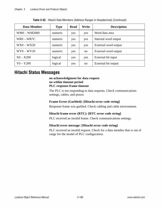
Chapter 3 Lookout Driver and Protocol Objects
Lookout Object Reference Manual 3-106 www.natinst.com
Hitachi Status Messagesno acknowledgment for data requestno within timeout periodPLC response frame timeout
The PLC is not responding to data requests. Check communications settings, cables, and power.
Frame Error (Garbled): [Hitachi error code string]
Response frame was garbled. Check cabling and cable environment.
Hitachi frame error (RTC): [RTC error code string]
PLC received an invalid frame. Check communications settings.
Hitachi error message: [Hitachi error code string]
PLC received an invalid request. Check for a data member that is out of range for the model of PLC configuration.
WM0 – WM2000 numeric yes yes Word data area
WR0 – WR7C numeric yes yes Internal word output
WX0 – WX20 numeric yes yes External word output
WY0 – WY20 numeric yes no External word output
X0 – X200 logical yes yes External bit input
Y0 – Y200 logical yes no External bit output
Table 3-32. Hitachi Data Members (Address Ranges in Hexadecimal) (Continued)
Data Member Type Read Write Description

Chapter 3 Lookout Driver and Protocol Objects
© National Instruments Corporation 3-107 Lookout Object Reference Manual
IPASCII IPASCII is a protocol driver class Lookout uses to communicate with any IP device that runs standard TCP or UDP services.
An IPASCII object contains no predefined data points. When you create a IPASCII object, you must define your data request strings as well as the template Lookout uses to parse the response frame.
Local port specifies which local Ethernet I/O port the object uses for communicating to the external device.
Mode indicates whether the object will use a TCP socket or a UDP socket.
IP address indicates the address of the device you wish to communicate with.
Port indicates the Ethernet I/O port number on the remote device where the object will try to establish a socket.
Accept Unsolicited Messages indicates whether or not the object will report packets from the device that are not in response to a request that the IPASCII object has sent it. This does not mean that the IPASCII object can act as a server. It means that once the IPASCII object has established a socket as a client, it reports unexpected data it receives from that point on.
Communication alarm priority determines the priority level of alarms generated by the IPASCII object. Such alarms are typically related to communications with the physical device.
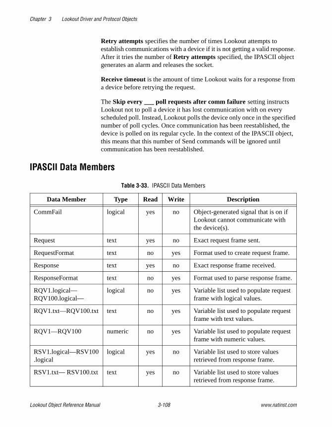
Chapter 3 Lookout Driver and Protocol Objects
Lookout Object Reference Manual 3-108 www.natinst.com
Retry attempts specifies the number of times Lookout attempts to establish communications with a device if it is not getting a valid response. After it tries the number of Retry attempts specified, the IPASCII object generates an alarm and releases the socket.
Receive timeout is the amount of time Lookout waits for a response from a device before retrying the request.
The Skip every ___ poll requests after comm failure setting instructs Lookout not to poll a device it has lost communication with on every scheduled poll. Instead, Lookout polls the device only once in the specified number of poll cycles. Once communication has been reestablished, the device is polled on its regular cycle. In the context of the IPASCII object, this means that this number of Send commands will be ignored until communication has been reestablished.
IPASCII Data Members
Table 3-33. IPASCII Data Members
Data Member Type Read Write Description
CommFail logical yes no Object-generated signal that is on if Lookout cannot communicate with the device(s).
Request text yes no Exact request frame sent.
RequestFormat text no yes Format used to create request frame.
Response text yes no Exact response frame received.
ResponseFormat text no yes Format used to parse response frame.
RQV1.logical— RQV100.logical—
logical no yes Variable list used to populate request frame with logical values.
RQV1.txt—RQV100.txt text no yes Variable list used to populate request frame with text values.
RQV1—RQV100 numeric no yes Variable list used to populate request frame with numeric values.
RSV1.logical—RSV100.logical
logical yes no Variable list used to store values retrieved from response frame.
RSV1.txt— RSV100.txt text yes no Variable list used to store values retrieved from response frame.
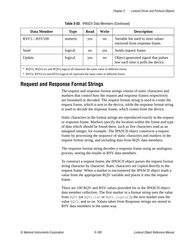
Chapter 3 Lookout Driver and Protocol Objects
© National Instruments Corporation 3-109 Lookout Object Reference Manual
Request and Response Format StringsThe request and response format strings consist of static characters and markers that control how the request and response frames respectively are formatted or decoded. The request format string is used to create the request frame, which is sent to the device, while the response format string is used to decode the response frame, which comes from the device.
Static characters in the format strings are reproduced exactly in the request or response frame. Markers specify the location within the frame and type of data which should be found there, such as five characters read as an unsigned integer, for example. The IPASCII object constructs a request frame by processing the sequence of static characters and markers in the request format string, and including data from RQV data members.
The response format string decodes a response frame using an analogous process, storing the results in RSV data members.
To construct a request frame, the IPASCII object parses the request format string character by character. Static characters are copied directly to the request frame. When a marker is encountered the IPASCII object reads a value from the appropriate RQV variable and places it into the request frame.
There are 100 RQV and RSV values provided for in the IPASCII object data member collection. The first marker in a format string uses the value from RQV1 (or RQV1.txt or RQV1.logical ), the next marker uses the value RQV2, and so on. Values taken from Response strings are stored in RSV data members in the same way.
RSV1—RSV100 numeric yes no Variable list used to store values retrieved from response frame.
Send logical no yes Sends request frame.
Update logical yes no Object-generated signal that pulses low each time it polls the device.
* RQVn, RQVn.txt and RQVn.logical all represent the same value in different forms.
* RSVn, RSVn.txt and RSVn.logical all represent the same value in different forms.
Table 3-33. IPASCII Data Members (Continued)
Data Member Type Read Write Description
Chapter 3 Lookout Driver and Protocol Objects
Lookout Object Reference Manual 3-110 www.natinst.com
Keep in mind that writing into RQV1 changes the value both for RQV1.text and RQV1.logical . Their only difference is the format in which they are represented. The same principle applies to the RSV data members.
Note There is no precedence to the order in which multiple objects connected to the same variable number will initialize upon opening the process file, such as the case in which a Pot object is connected to RQV1 while a TextEntry object is connected to RQV1.txt. You should take care to initialize such variables to the proper value after opening a process file.
To decode a response frame, the IPASCII object compares the response frame to the response format string character by character. The static characters in the response frame must match those in the response format string or the decoding process terminates. Static characters are, in effect, discarded by the IPASCII object as they are matched between the response format string and the response frame.
When the IPASCII object encounters a marker, it places the data indicated by the marker into the appropriate RSV data member.
The conversion of a portion of the response frame to a data type specified by a marker in the response format string must be valid, or the process will terminate.
If nothing halts the process, decoding terminates when the end of the response frame string is reached.
There are examples of both request frames and response frames at the end of this section, but for the examples to make sense, you must first understand the IPASCII object markers.
MarkersThe general format for a marker is:
%[width][type]
Each field in the marker format is a single character or a number signifying a particular format option.
The % sign denotes the beginning of the marker. If the percent sign is followed by a character that has no meaning as a format-control character, that character and the following characters (up to the next percent sign) are treated as static characters, that is, a sequence of characters that must match the frame exactly. For example, to specify that a percent-sign character is a static character part of the frame, use %%.

Chapter 3 Lookout Driver and Protocol Objects
© National Instruments Corporation 3-111 Lookout Object Reference Manual
Width is a positive decimal integer specifying the number of characters that particular value occupies in the frame. By default IPASCII will pad the value with blank spaces if the value takes up fewer characters than the value specified by width. Including a 0 before the width value forces the IPASCII object to pad with zeroes instead of blank spaces.
Type determines whether the field is interpreted as a character, a string, or a number.
The simplest format specification contains only the percent sign and a type character (for example, %s). That would place the value in the response frame in the RSV1.txt data member.
The request format string also has a precision value in the form %[width].[precision][type] . This specifies the number of digits to the right of the decimal point, if any, in the request frame. If you use a float (%f) and do not specify a precision value, the IPASCII object assumes a default of 6.
Characters are converted and stored in RSV data members from response frames in the order they are encountered in the response format. However, fewer than [width] characters may be read if a white-space character (space, tab, or newline) or a character that cannot be converted according to the given format occurs before [width] is reached.
Table 3-34. Data Types Allowed by IPASCII
Character Data Type
d Decimal integer
x, X Hexadecimal integer
u Unsigned decimal integer
f Floating-point
s String
b Byte (binary)
Request Format String RQV1 Request Frame
>%5d 34 > 34
>%05d 34 >00034

Chapter 3 Lookout Driver and Protocol Objects
Lookout Object Reference Manual 3-112 www.natinst.com
Values needed for request frames come from the RQV data members, and are also used in the order in which they occur in the request format.
To read strings not delimited by space characters, or that contain spaces, you can substitute a set of characters in brackets ([ ] ) s (string) type character. The corresponding input field is read up to the first character that does not appear in the bracketed character set. Using a caret (^ ) as the first character in the set reverses this effect: the IPASCII object reads input field up to the first character that does appear in the rest of the character set.
Notice that %[a-z] and %[z-a] are interpreted as equivalent to %[abcde...z], and that the character set is case sensitive.
Note The brackets only work in response format strings. They have no effect in the request format string.
The IPASCII object scans each field in the response frame character by character. It may stop reading a particular field before it reaches a character for a variety of reasons:
• The specified width has been reached.
• The next character cannot be converted as specified.
• The next character conflicts with a character in the response format string that it is supposed to match.
• The next character fails to appear in a given character set.
No matter what the reason, when the IPASCII object stops reading an field, the next field is considered to begin at the first unread character. The conflicting character, if there is one, is considered unread and is the first character of the next field.
ResponseFormat String RSV1.txt
ResponseFrame
$[A – Z,a – z, ]$ Natl Inst $Natl Inst$
>[^,s] days >day

Chapter 3 Lookout Driver and Protocol Objects
© National Instruments Corporation 3-113 Lookout Object Reference Manual
Entering the Format StringFor a static connection to one of the format data members, enter your format string in the yellow field box in the Edit Connections dialog box. Remember to begin and end the format strings with quotation marks so that Lookout will accept the string input.
You can also connect any valid text data member, such as a text entry object, to the format data members.
Request Frame Construction Examples
A zero in front of the four pads with zeroes; a space pads with spaces.
Response Format Examples
Note The decimal point counts as a character when decoding floats (%f). Also, decimal points denoting precision are not allowed when decoding a float in the response frame.
RequestFormat String RQV
RequestFrame
<01%4u%s RQV1=1234 RQV2.txt=Ross
<011234Ross
<01%04u%s RQV1=34 RQV2.txt=Ross
<010034Ross
<01% 4u%s RQV1=34 RQV2.txt=Ross
<01 34Ross
ResponseFrame
ResponseFormat String RSV
*(16.38: *(%5.2f: RSV1=16.38
ResponseFrame
ResponseFormat String RSV
>>Test Text<< >>%s<< RSV1.txt=Test

Chapter 3 Lookout Driver and Protocol Objects
Lookout Object Reference Manual 3-114 www.natinst.com
The space between the words terminates the conversion. See the preceding bracketed character example in order to span a space or other special characters. The response format uses a space as a delimiter.
IPASCII Error MessagesNo response from device within timeout period
Lookout received no response from the device within the Receive timeout period. The IPASCII object was able to establish a socket, but when it sends its message to the device, it does not respond—as if it is not even there. You may have to significantly increase Receive timeout (and Poll Rate) to ensure Lookout is allowing enough time to receive the expected response. Also, verify your cable connections, power, configuration settings, and IP settings.
Not enough data to send a valid frame
This means that the IPASCII object has not received enough data to fill in all the variables in the Request Format frame. This could mean that you do not have connections made to all of the RQVs that the IPASCII object is expecting.
Socket communications error
This alarm message will be followed by a Windows standard socket error message. The most common reason you might see one of these errors is if an error has occurred on the socket after a valid socket has already been established.
Cannot communicate with device
This means that the IPASCII object was not able to establish a valid socket with the remote device, and in fact did not get any kind of response from the device.
Cannot resolve IP address
Check to make sure you have given IPASCII a valid IP address.
ResponseFrame
ResponseFormat String RSV
>>Test Text<< >>%s%s<< RSV1.txt=TestRSV2.txt=Text
>>DogCat<< >>%3s%3s<< RSV1.txt=DogRSV2.txt=Cat

Chapter 3 Lookout Driver and Protocol Objects
© National Instruments Corporation 3-115 Lookout Object Reference Manual
Cannot resolve port
Check to make sure you have given IPASCII a valid port number on the remote device.
Garbled or unexpected response
IPASCII got a response frame, but static characters in the response did not match up to the response format string.
Illegally formatted string received
IPASCII got a response frame, but certain characters in the response were not in the format stated by the markers in the response format string.
Related Objects ASCII
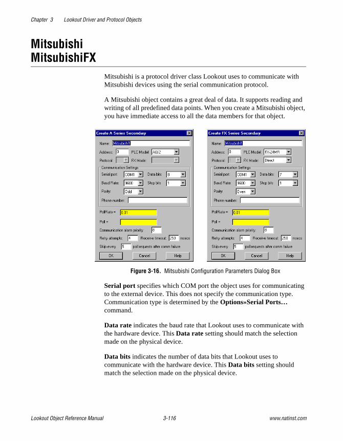
Chapter 3 Lookout Driver and Protocol Objects
Lookout Object Reference Manual 3-116 www.natinst.com
MitsubishiMitsubishiFX
Mitsubishi is a protocol driver class Lookout uses to communicate with Mitsubishi devices using the serial communication protocol.
A Mitsubishi object contains a great deal of data. It supports reading and writing of all predefined data points. When you create a Mitsubishi object, you have immediate access to all the data members for that object.
Figure 3-16. Mitsubishi Configuration Parameters Dialog Box
Serial port specifies which COM port the object uses for communicating to the external device. This does not specify the communication type. Communication type is determined by the Options»Serial Ports… command.
Data rate indicates the baud rate that Lookout uses to communicate with the hardware device. This Data rate setting should match the selection made on the physical device.
Data bits indicates the number of data bits that Lookout uses to communicate with the hardware device. This Data bits setting should match the selection made on the physical device.

Chapter 3 Lookout Driver and Protocol Objects
© National Instruments Corporation 3-117 Lookout Object Reference Manual
Stop bits indicates the number of stop bits that Lookout uses to communicate with the hardware device. This Stop bits setting should match the selection made on the physical device.
Parity indicates the parity that Lookout uses to communicate with the hardware device. This Parity setting should match the selection made on the physical device.
Phone number specifies the number to be dialed if the selected serial port is configured for dial-up. This Phone number only applies to the individual protocol object.
PollRate is a numeric expression that determines how often to poll the device. The object then polls the device at the specified time interval. Normally, this is a simple time constant such as 0:01 (one second). See Numeric Data Members in Chapter 2, How Lookout Works, of the Getting Started with Lookout manual for more information on entering time constants.
Poll is a logical expression. When this expression changes from FALSE to TRUE, Lookout polls the device. You can use a simple expression like the signal from a pushbutton, or a complex algorithm.
Communication alarm priority determines the priority level of alarms generated by the Mitsubishi object. Such alarms are typically related to communications with the physical device.
Retry attempts specifies the consecutive number of times Lookout attempts to establish communications with a device when it is not getting a valid response. After it tries the number of Retry attempts specified, the Mitsubishi object generates an alarm and releases the communication port back to the communications subsystem. The subsystem then moves on to the next device in the polling queue (if any). See Chapter 3, Serial Communications, in the Lookout Developer’s Manual for more information.
Receive timeout is the time delay Lookout uses in waiting for a response from a device before retrying the request.
The Skip every… setting instructs Lookout not to poll a device it has lost communication with on every scheduled poll. Instead, Lookout skips the device in the polling cycle. Once communications have been reestablished, the device is polled on its regular cycle.

Chapter 3 Lookout Driver and Protocol Objects
Lookout Object Reference Manual 3-118 www.natinst.com
Mitsubishi Data MembersAs with all Lookout drivers, you can access I/O points and other data through data members. The following is a table of data members currently supported by the Mitsubishi object class.
Table 3-35. Mitsubishi Data Members (A Series)
Data Member Type Read Write Description
C0–C1023 numeric yes yes Counter, 16-bit word.
CommFail logical yes no Object-generated signal, ON if Lookout cannot communicate with the device(s).
D0–D1023 numeric yes yes Data register, 16-bit word.
M0–M2047 logical yes yes Discrete coil, 1-bit.
Poll logical no yes When this expression transitions from FALSE to TRUE, Lookout polls the device.
PollRate numeric no yes Lookout expression that determines the device polling frequency.
T0–T1023 numeric yes yes Timer, 16-bit word.
Update logical yes no Object-generated signal that pulses low each time it polls the device.
W0–W1023 numeric yes yes Data register, 16-bit word.
X0–X2047 logical yes no Discrete input, 1-bit.
Y0–Y2047 logical yes yes Discrete output, 1-bit.
Table 3-36. MitsubishiFX Data Members (FX Series)
Data member Type Read Write Description
C0–C1023 numeric yes yes Counter, 16-bit word.
CommFail logical yes no Object-generated signal that is ON if Lookout cannot communicate with the device(s).
D0–D1023 numeric yes yes Data register, 16-bit word.
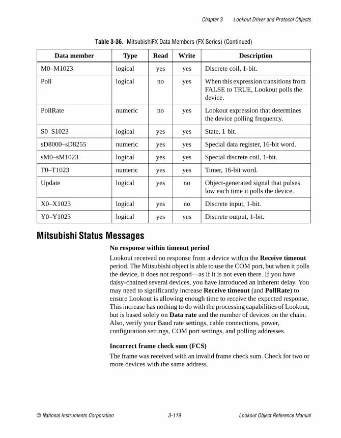
Chapter 3 Lookout Driver and Protocol Objects
© National Instruments Corporation 3-119 Lookout Object Reference Manual
Mitsubishi Status MessagesNo response within timeout period
Lookout received no response from a device within the Receive timeout period. The Mitsubishi object is able to use the COM port, but when it polls the device, it does not respond—as if it is not even there. If you have daisy-chained several devices, you have introduced an inherent delay. You may need to significantly increase Receive timeout (and PollRate) to ensure Lookout is allowing enough time to receive the expected response. This increase has nothing to do with the processing capabilities of Lookout, but is based solely on Data rate and the number of devices on the chain. Also, verify your Baud rate settings, cable connections, power, configuration settings, COM port settings, and polling addresses.
Incorrect frame check sum (FCS)
The frame was received with an invalid frame check sum. Check for two or more devices with the same address.
M0–M1023 logical yes yes Discrete coil, 1-bit.
Poll logical no yes When this expression transitions from FALSE to TRUE, Lookout polls the device.
PollRate numeric no yes Lookout expression that determines the device polling frequency.
S0–S1023 logical yes yes State, 1-bit.
sD8000–sD8255 numeric yes yes Special data register, 16-bit word.
sM0–sM1023 logical yes yes Special discrete coil, 1-bit.
T0–T1023 numeric yes yes Timer, 16-bit word.
Update logical yes no Object-generated signal that pulses low each time it polls the device.
X0–X1023 logical yes no Discrete input, 1-bit.
Y0–Y1023 logical yes yes Discrete output, 1-bit.
Table 3-36. MitsubishiFX Data Members (FX Series) (Continued)
Data member Type Read Write Description

Chapter 3 Lookout Driver and Protocol Objects
Lookout Object Reference Manual 3-120 www.natinst.com
Incorrect PC number in response
The frame received had an incorrect source address. Check for two or more devices with the same address.
Incorrect command in response
The frame received had an incorrect command. Check for two or more devices with the same address.
Garbled or Invalid frame
The frame was received without proper termination character (ETX). Check the Lookout Receive Gap setting.
No acknowledgment for write frame
The write frame was not acknowledged by the PC. Check the address of Mitsubishi object or the address range of the PC.
Mitsubishi errors reported in the response
These errors are reported by the Mitsubishi device, and are in turn reported to the user in text form.
Mitsubishi Models SupportedA series:
A0J2, A0J2H, A1, A1S, A1N, A1E, A2, A2n, A2C, A2E, A3, A3N, A3E, A3H, A3M.
FX series:
All models through March, 1997.

Chapter 3 Lookout Driver and Protocol Objects
© National Instruments Corporation 3-121 Lookout Object Reference Manual
Modbus ModbusMOSCAD
Modbus and ModbusMOSCAD are protocol driver classes Lookout uses to communicate with equipment such as programmable logic controllers (PLCs), remote terminal units (RTUs), or any other piece of equipment using Modbus Serial (ASCII or RTU) or Modbus Plus communication protocol.
The Modbus object class has general-purpose addresses, such as holding register 40001, and is suitable for communicating with nearly all Modbus devices, including the Control Microsystems TeleSAFE RTU.
The ModbusMOSCAD object class works with Motorola MOSCAD PLCs and RTUs. It also uses the Modbus Serial (ASCII or RTU) or Modbus Plus communication protocol, but its data members reflect the address of Motorola MOSCAD devices.
You can limit the number of channels Lookout uses on the SA-85 card by creating a modbus.ini file in the Lookout directory, as shown in the following example.
[ALL]
MaxChannels=channel
where channel is a number between 1 and 8, inclusive (default = 8).
These protocol driver objects contain a great deal of data. All readable and writable members (inputs/outputs), polling instructions, read/write blocking, serial port usage, and so on are bundled with the object. Therefore, as soon as you create a Modbus or ModbusMOSCAD object you immediately have access to all the object data members (see data member list in Table 3-38).
Note Lookout protocol driver objects automatically generate an efficient read/write blocking scheme based on the inputs and outputs being used in your process file. You are not required to build your own I/O blocking table.

Chapter 3 Lookout Driver and Protocol Objects
Lookout Object Reference Manual 3-122 www.natinst.com
As protocol drivers, both object classes conform to the specifications in the Modicon Modbus Protocol Reference Guide PI-MBUS-300 Rev. C. The drivers support ASCII and RTU transmission modes, as well as Modbus Plus.
Figure 3-17. Modbus Configuration Parameters Dialog Box
In this example, Lookout is connected to a Modbus-speaking PLC with an address of 5 using serial port 1 (which was previously configured for hardwired communications), and polling the device every second.
Modbus Serial indicates that the slave device talks either Modbus ASCII or Modbus RTU. When you select this option, Lookout first tries to communicate using the RTU format. If unsuccessful, it then tries the ASCII format (a little slower). If your network is susceptible to repeated communication problems, and if these problems slow scanning considerably, you may want to disable Lookout from retrying both formats. This can speed communication retries by Lookout; however, it will not fix your communication problems. Call National Instruments technical support to for information on how to prohibit Lookout from trying to communicate using both formats.
Modbus Plus Network indicates that the slave device is connected to the Lookout computer via a Modbus Plus network card.
Note NetBIOS-based networking software typically uses software interrupt 5C. This is also the default software interrupt used by the Modbus Plus Network card driver. Change the Modbus Plus software interrupt from 5C to 5D, 5E, or 5F. Refer to your Modicon documentation for instructions on changing the software interrupt setting.

Chapter 3 Lookout Driver and Protocol Objects
© National Instruments Corporation 3-123 Lookout Object Reference Manual
Modbus Ethernet indicates you are communicating with the Modbus slave device using an Ethernet connection.
If you select Modbus Serial, you must specify Address, Serial Port, Data Rate, Parity, Data Bits, and Stop Bits. And if you are using a Dial-up modem connected to your communication port, you must also specify a Phone Number.
If you select Modbus Plus Network, you need only specify the remote device Address.
If you select Modbus Ethernet you must specify the IP address in addition to Alarm Priority , Poll Rate, Poll Retry attempts, and Receive timeout.
Address is a slave address and refers to the PLC or RTU address setting as set on the device dip switches. If devices share a common line, they require unique addresses (1 to 255).
IP address is the Internet Protocol address for the Modbus slave object you are communicating with.
Serial port specifies which port the object uses for communication to the external device. This does not specify the communication type. Communication type is determined by the Options»Serial Ports… command.
Data rate, Parity, Data bits, and Stop bits reference the settings on the hardware device.
The Defaults button replaces the current settings with default values.
Alarm priority determines the priority level of Modbus-generated alarms.
Phone number specifies the number to be dialed if the serial port setting is configured for dial-up. This number only applies to the individual protocol object.
PollRate is a numeric expression that determines how often to poll the device. Modbus then polls the device at the specified time interval. Normally, this is a simple time constant such as 0:01 (one second). See Numeric Data Members in Chapter 2, How Lookout Works, of the Getting Started with Lookout manual for information on entering time constants.

Chapter 3 Lookout Driver and Protocol Objects
Lookout Object Reference Manual 3-124 www.natinst.com
Poll is a logical expression. When this expression changes from FALSE to TRUE, Lookout polls the device. You can use a simple expression like the signal from a pushbutton, or a complex algorithm.
Retry attempts specifies the consecutive number of times Lookout attempts to establish communications with a device if it is not getting a valid response. After it tries the number of Retry attempts specified, the Modbus object generates an alarm and releases the communication port back to the communications subsystem which then moves on to the next device in the polling queue (if any). Refer to Chapter 3, Serial Communications, in the Lookout Developer’s Manual for more information.
Receive timeout is the time delay Lookout uses in waiting for a response from a device before retrying the request.
Advanced Modbus ParametersThe Modbus driver attempts to block the reads and writes of coils, input registers and holding registers into groups to maximize communication efficiency. Through the Advanced Modbus Options dialog box, you can control the maximum block sizes that the driver uses. In fact, if your device does not support the default block sizes, you may have to specify smaller blocks.
The Advanced… button invokes the Advanced Modbus Options dialog box you can use to customize specific options within the Modbus protocol.

Chapter 3 Lookout Driver and Protocol Objects
© National Instruments Corporation 3-125 Lookout Object Reference Manual
Figure 3-18. Advanced Modbus Parameters Dialog Box
The Modbus object class uses Modbus Function Codes 01, 02, 03, 04, 05, 06, 15, and 16; and expects the remote I/O device to support these codes as specified by Modbus. The driver can communicate with up to 247 Modbus slave devices on each serial port.
The Maximum values per message settings specify the maximum number of elements Lookout attempts to read (fc 1 – fc 4 ), or write (fc 15 and fc 16 ), in a single Modbus message. The default values represent the maximum number of elements that the protocol can transmit in a single message, and provides optimal speed. However, some devices are not capable of handling the maximum number of elements, so you should set the values according to the documentation for those devices.
If the Immediately write outputs option is ON, Lookout immediately polls the device any time a value changes that is being written out to the device. If it is OFF, Lookout waits until the next scheduled poll to write out changed values.
The Skip every… setting instructs Lookout to not poll a device it has lost communication with on every scheduled poll. Instead, Lookout skips the device in the polling cycle accordingly. Once communications have been reestablished, the device is polled on its regular cycle.
The Daniel option is device-dependent and instructs Lookout to treat holding registers as 32-bit IEEE floating values instead of 16-bit values. If you set this flag, you must also set your hardware device to treat holding

Chapter 3 Lookout Driver and Protocol Objects
Lookout Object Reference Manual 3-126 www.natinst.com
registers as 32-bit floats—most devices do not support this option, but Bristol-Babcock RTUs and Daniel flow meters do.
Note Activating the Daniel option deactivates all Modbus holding register members (on that device) except for 40001 – 49999 and 4000001 – 465000. If you attempt to read D40001, for example, the returned value is 0, and Lookout will not attempt to write D40001 to the RTU. Of course, in devices that do not support this option, you can still read and write two adjacent holding registers as a floating point value with the Modbus data members F40001 – F4999. In fact, this is a more general purpose solution than the Daniel option, because you can still read bits and word values out of the holding registers, too.
Some Modbus PLCs reverse byte order in a floating point data member. If your process is returning garbled or senseless floating point values, select the Modicon 32-bit floating point order (0123 vs. 3210) option in the Advanced Modbus Options dialog box. This option chooses whether the characters within the floating point registers (data members F40001 –
F49999 and F400001 – F465000 ) are in little endian or big endian format.
On occasion a Modbus PLC will direct a message to your process. To poll for all data member values following receipt of such a poll, select the Poll on receipt of unsolicited message option in the Advanced Modbus Options dialog box. Using this option is a way to force a poll of a Modbus device based on an event, without reference to the configured poll intervals and somewhat outside the usual Lookout event-driven action.
Caution Notice that the D and F data members read two adjacent registers as single, 32-bit numbers. One consequence of this is that if you connect to two adjacent registers, such as D40010 and D40011 , you will get incorrect values because of overlapping. Make sure that you do not connect to adjacent registers with the D or F data members.
Modbus Protocol StatisticsThe driver monitors Modbus Protocol Statistics. This data is held within readable data members of the Modbus object and you can see them in the Modbus Protocol Statistics dialog box. To view the dialog box, select Options»Modbus… and click on Statistics….
Note The Options»Modbus… option is only visible in the Options menu if a Modbus object was previously created in your Lookout application.
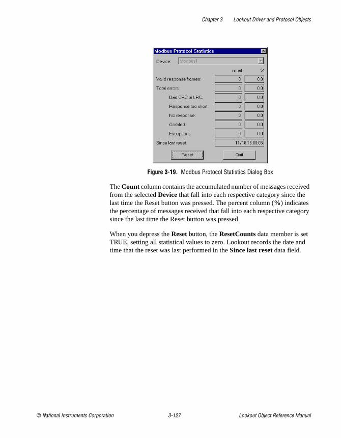
Chapter 3 Lookout Driver and Protocol Objects
© National Instruments Corporation 3-127 Lookout Object Reference Manual
Figure 3-19. Modbus Protocol Statistics Dialog Box
The Count column contains the accumulated number of messages received from the selected Device that fall into each respective category since the last time the Reset button was pressed. The percent column (% ) indicates the percentage of messages received that fall into each respective category since the last time the Reset button was pressed.
When you depress the Reset button, the ResetCounts data member is set TRUE, setting all statistical values to zero. Lookout records the date and time that the reset was last performed in the Since last reset data field.

Chapter 3 Lookout Driver and Protocol Objects
Lookout Object Reference Manual 3-128 www.natinst.com
Modbus Data MembersThe Modbus object class supports both 5-digit and 6-digit addressing. When you use a 6 digit address, the left-most digit represents the address type as follows:
The remaining 5 digits represent the actual address of the coil, input or holding register.
Note When you reference address 000001 and address 1, you are referring to the same point, but 40001 and 040001 do not refer to the same point. Because zero is the left-most digit in the 6-digit address, 040001 points to the 40001st single-bit coil and 40001 refers to the first holding register.
Table 3-37. 6-Digit Address Coding
First Digit Address Type
0 Single-bit coils
1 Discrete inputs
3 Input registers
4 Holding registers
Table 3-38. Modbus Data Members
Data Member Type Read Write Description
000001 – 065000 logical yes yes 6-digit addresses of single-bit coils
1 – 9999 logical yes yes Single-bit coils
100001 – 165000 logical yes no 6-digit addresses of single-bit discrete inputs
10001 – 19999 logical yes no Single bit discrete inputs
300001 – 365000 numeric yes no 6-digit addresses of 16-bit input registers encoded as unsigned binary integers ranging from 0 to 65535
30001 – 39999 numeric yes no 16-bit input registers encoded as unsigned binary integers ranging from 0 to 65535

Chapter 3 Lookout Driver and Protocol Objects
© National Instruments Corporation 3-129 Lookout Object Reference Manual
400001 – 465000 numeric yes yes 6-digit addresses of 16-bit input registers encoded as unsigned binary integers ranging from 0 to 65535
400001.1 – 465000.16 logical yes yes 6-digit address used to access individual bits out of holding registers and read them as logical ON/OFF values. The least significant bit is 1; the most significant, 16.
40001 – 49999 numeric yes yes 16-bit holding registers encoded as unsigned binary integers ranging from 0 to 65535
40001.1 – 49999.16 logical yes yes Access individual bits out of holding registers and read them as logical ON/OFF values. The least significant bit is 1; the most significant, 16.
BadCRC numeric yes no Number of responses from device whose message failed the cyclic redundancy check (CRC) or the longitudinal redundancy check (LRC)
BCD300001 – BCD365000
numeric yes no 6-digit addresses of 16-bit input registers encoded as binary-coded decimal integers ranging from 0 to 9999
BCD30001 – BCD39999
numeric yes no 16-bit input registers encoded as binary-coded decimal integers ranging from 0 to 9999
BCD400001 – BCD465000
numeric yes yes 6-digit addresses of 16-bit holding registers encoded as binary-coded decimal integers ranging from 0 to 9999
BCD40001 – BCD49999
numeric yes yes 16-bit holding registers encoded as binary-coded decimal integers ranging from 0 to 9999
Table 3-38. Modbus Data Members (Continued)
Data Member Type Read Write Description

Chapter 3 Lookout Driver and Protocol Objects
Lookout Object Reference Manual 3-130 www.natinst.com
CommFail logical yes no Driver-generated signal that is ON if Lookout cannot communicate with the device for whatever reason
D400001 – D465000 numeric yes yes 6-digit addresses of 32-bit unsigned holding register—reads two adjacent holding registers as a single 32-bit number ranging from 0 to 4,294,967,296.
D40001 – D49999 numeric yes yes 32-bit unsigned holding register—reads two adjacent holding registers as a single 32-bit number ranging from 0 to 4,294,967,296.
Exceptions numeric yes no Number of responses from device whose message was understandable to the driver but included an error code indication from the device
F400001 – F465000 numeric yes yes 6-digit addresses of 32-bit IEEE floating point register—reads two adjacent holding registers as a single 32-bit floating point value
F40001 – F49999 numeric yes yes 32-bit IEEE floating point register—reads two adjacent holding registers as a single 32-bit floating point value
Garbled numeric yes no Number of responses from device whose message was unintelligible to the driver
NoResponse numeric yes no Number of polls generated by driver not responded to by device
OffHook logical no yes When TRUE, this flag instructs the Modbus object to retain exclusive use of its assigned communication port
Poll logical no yes When this expression transitions from FALSE to TRUE, Lookout polls the device.
Table 3-38. Modbus Data Members (Continued)
Data Member Type Read Write Description

Chapter 3 Lookout Driver and Protocol Objects
© National Instruments Corporation 3-131 Lookout Object Reference Manual
Comments You can use the OffHook data member to enhance communications when using the Modbus object class with dial-up modems. When OffHook is TRUE and the serial port is connected to a dial-up modem, the Modbus object does not hang up the modem when the poll is complete. Rather, it keeps the phone off the hook, retaining exclusive use of the serial port. As long as OffHook is TRUE, the Modbus object continues to poll the same PLC without hanging up the modem.
As soon as OffHook goes FALSE, the object releases the serial port to the communications subsystem, which goes to the next poll request in the queue, if any. The object also releases the port if data communications are lost for any reason—such as if the PLC modem breaks the connection.
PollRate numeric no yes Lookout expression that determines the device polling frequency.
ProtocolErrors numeric yes no Total number of bad messages received from polled device
ResetCounts logical no yes Resets number to zero in the following data members: ValidFrame, NoResponse, TooShort, BadCRC, Garbled, Exceptions, & ProtocolErrors
S400001 – S465000 numeric yes yes 6-digit addresses of 16-bit holding registers encoded as signed binary integers ranging from –32767 to +32768.
S40001 – S49999 numeric yes yes 16-bit holding registers encoded as signed binary integers ranging from –32767 to +32768.
TooShort numeric yes no Number of responses from device whose message length was too short
Update logical yes no Driver-generated signal that pulses each time the driver polls the device
ValidFrame numeric yes no Number of good messages received from polled device
Table 3-38. Modbus Data Members (Continued)
Data Member Type Read Write Description

Chapter 3 Lookout Driver and Protocol Objects
Lookout Object Reference Manual 3-132 www.natinst.com
When using OffHook, consider defining the driver object PollRate to poll fast when OffHook is TRUE, and poll at its normal rate when OffHook is FALSE. You might tie a Switch object to the OffHook writable data member for this very purpose.
ModbusMOSCAD Data Members
Table 3-39. ModbusMOSCAD Data Members
Data Member Type Read Write Description
AI0r0c0 – AI30r255c7 numeric yes no Each address represents a 16-bit analog input encoded as an unsigned integer ranging from 0 to 65535
AO0r0c0 – AO30r255c7 numeric yes yes Each address represents a 16-bit analog output encoded as an unsigned integer ranging from 0 to 65535
BadCRC numeric yes no Number of responses from device whose message failed the cyclic redundancy check (CRC) or the longitudinal redundancy check (LRC)
CommFail logical yes no Driver-generated signal that is ON if Lookout cannot communicate with the device for whatever reason
DI0r0c0.0 – DI30r255c7.15
logical yes no Each address represents an individual discrete input read as a logical ON/OFF value. The least significant bit is 0; the most significant, 15.
DO0r0c0.0 – DO30r255c7.15
logical no yes Each address represents an individual discrete input read as a logical ON/OFF value. The least significant bit is 0; the most significant, 15.
Exceptions numeric yes no Number of responses from device whose message was understandable to the driver but included an error code indication from the device
Garbled numeric yes no Number of responses from device whose message was unintelligible to the driver

Chapter 3 Lookout Driver and Protocol Objects
© National Instruments Corporation 3-133 Lookout Object Reference Manual
Comments To specify the address of an analog input located in row 22, column 1 of Table 12, you would enter AI12r22c1, where
NoResponse numeric yes no Number of polls generated by driver not responded to by device
Poll logical no yes When this expression transitions from FALSE to TRUE, Lookout polls the device.
PollRate numeric no yes Lookout expression that determines the device polling frequency.
ProtocolErrors numeric yes no Total number of bad messages received from polled device
ResetCounts logical no yes Resets number to zero in the following data members: ValidFrame, NoResponse, TooShort, BadCRC, Garbled, Exceptions, & ProtocolErrors
TooShort numeric yes no Number of responses from device whose message length was too short
Update logical yes no Driver-generated signal that pulses each time the driver polls the device
ValidFrame numeric yes no Number of good messages received from polled device
Table 3-39. ModbusMOSCAD Data Members (Continued)
Data Member Type Read Write Description
AI 12 r22 clSignal Type
Table Number
Column Number in Table
Row Number in Table

Chapter 3 Lookout Driver and Protocol Objects
Lookout Object Reference Manual 3-134 www.natinst.com
ModbusSlaveModbusSlave is an object class Lookout uses to act as a slave to equipment such as PLCs, distributed control systems (DCSs), or any other device that can act as a Modbus master. The ModbusSlave object enables Lookout to respond to unsolicited messages generated by other devices on a Modbus protocol network.
Applications include:
• PLCs and/or RTUs dial up a Lookout application over a non-dedicated phone line when there is an alarm or event that must be reported (unsolicited report-by-exception).
• Two Lookout packages communicate with each other over radio. One uses a Modbus object and the other uses a ModbusSlave object.
• Lookout, directly connected to a Modbus network, responds to polls from a DCS as a Modbus slave.
Think of the ModbusSlave object as representing a virtual PLC within Lookout. It can receive reads and writes over a Modbus protocol-based network. Like the Modbus object, the ModbusSlave object has a collection of readable and writable data members, all created when you define the ModbusSlave object.
You can create a unique ModbusSlave object for every master PLC, or you can create a single ModbusSlave object for multiple master PLCs. In the latter case, one master might write to one group of registers within the ModbusSlave object and another master might write to another group of registers within the ModbusSlave object.
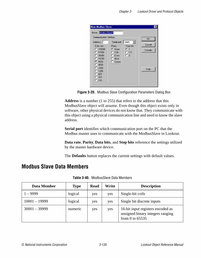
Chapter 3 Lookout Driver and Protocol Objects
© National Instruments Corporation 3-135 Lookout Object Reference Manual
Figure 3-20. Modbus Slave Configuration Parameters Dialog Box
Address is a number (1 to 255) that refers to the address that this ModbusSlave object will assume. Even though this object exists only in software, other physical devices do not know that. They communicate with this object using a physical communication line and need to know the slave address.
Serial port identifies which communication port on the PC that the Modbus master uses to communicate with the ModbusSlave in Lookout.
Data rate, Parity, Data bits, and Stop bits reference the settings utilized by the master hardware device.
The Defaults button replaces the current settings with default values.
Modbus Slave Data Members
Table 3-40. ModbusSlave Data Members
Data Member Type Read Write Description
1 – 9999 logical yes yes Single-bit coils
10001 – 19999 logical yes yes Single bit discrete inputs
30001 – 39999 numeric yes yes 16-bit input registers encoded as unsigned binary integers ranging from 0 to 65535

Chapter 3 Lookout Driver and Protocol Objects
Lookout Object Reference Manual 3-136 www.natinst.com
40001 – 49999 numeric yes yes 16-bit holding registers encoded as unsigned binary integers ranging from 0 to 65535
BCD30001 – BCD39999
numeric yes yes 16-bit input registers encoded as binary-coded decimal integers ranging from 0 to 9999
BCD40001 – BCD49999
numeric yes yes 16-bit holding registers encoded as binary-coded decimal integers ranging from 0 to 9999
D30001 – D39999 numeric yes yes 32-bit input register
D40001 – D49999 numeric yes yes 32-bit unsigned holding register—reads two adjacent holding registers as a single 32-bit number ranging from 0 to 4,294,967,296.
F30001 – F39999 numeric yes yes 32-bit input register
F40001 – F49999 numeric yes yes 32-bit IEEE floating point register—reads two adjacent holding registers as a single 32-bit floating point value
H40001.f1 – H49999.f16
logical yes yes Access individual bits out of holding registers and read them as logical ON/OFF values. The least significant bit is F1 and the most significant bit is F16.
S40001 – S49999 numeric yes yes 16-bit holding registers encoded as signed binary integers ranging from –32767 to +32768.
Table 3-40. ModbusSlave Data Members (Continued)
Data Member Type Read Write Description

Chapter 3 Lookout Driver and Protocol Objects
© National Instruments Corporation 3-137 Lookout Object Reference Manual
National Instruments FieldbusLookout can communicate with Fieldbus devices using the National Instruments NI-FBUS AT card.
The Lookout Fieldbus objects contain no inherent physical data members. All physical data members are obtained by reading Device Descriptions (DD). A default DD is provided when you install the National Instruments Fieldbus card which contains all the standard Fieldbus blocks. Lookout creates a Fieldbus object class dynamically for every uniquely named block found in any of the DDs. If a block is defined more than once by name, then the user is able select which DD block definition to apply to the Lookout object in the object creation dialog box. The National Instruments supplied DD is selected by default.
In order to add or remove a Fieldbus block type to the Lookout object class list, delete the Lookout.dat file in the \Lookout directory and restart Lookout. This forces Lookout to re-index all of its subordinate object classes. The name of Fieldbus object classes is the name of the block preceded by FF_. For example, the Lookout class name for an Analog Input block would be FF_Analog_Input .
Lookout also supports manufacturer supplied DDs. These DDs must be placed in the appropriate directory structure as defined by the Fieldbus Foundation. You can configure the base directory for manufacturer supplied DDs with the National Instruments NI-FBUS Config software. After selecting DD Info in the main dialog box of the NI-FBUS Config software, enter the path for your base directory. The DD should be placed, along with its symbol file, two folders below this base directory. Conventions for naming these directories are outlined by Fieldbus Foundation but the names are not used by Lookout.
When re-indexing occurs, Lookout looks into every DD in the directory system for Fieldbus blocks. Lookout also requires a symbol file (*.sym ) for every DD (*.ffo ).
Note DD must be made with tokenizer version 4.2 or greater.

Chapter 3 Lookout Driver and Protocol Objects
Lookout Object Reference Manual 3-138 www.natinst.com
Figure 3-21. Fieldbus Configuration Parameters Dialog Box
Name is the Lookout name and is used to reference this object in Lookout.
Copy Fieldbus Name replaces invalid characters in the Fieldbus Name with underscores while copying the Fieldbus Name into the Lookout Name edit box.
Fieldbus Name shows a list of all Fieldbus blocks, of the appropriate type, available on your network. This list comes from comparing the DD_Item_Type of the block on the networks with the type of object that the user has selected to create. If there are no devices in this listbox, you can click the Show all blocks checkbox and select the Rescan button to show Fieldbus blocks of all types on the network.
Note Lookout treats the block selected as the type of block the user was trying to make. If an incorrect block is selected, the wrong parameter list appears for that block and invalid data request may occur.
Device Description contains a list of Device Descriptions that have definitions for the block the user is about create. The parameter list for each definition may vary. Care should be taken in selecting the proper DD for the block this Lookout object will represent.
PollRate is a numeric expression that determines how often to poll the device. The object then polls the device at the specified time interval. Normally, this is a simple time constant such as 0:01 (one second). See Numeric Data Members in Chapter 2, How Lookout Works, of the Getting Started with Lookout manual for information on entering time constants.
Retry is the number of Fieldbus communication alarms to ignore before reporting an alarm.

Chapter 3 Lookout Driver and Protocol Objects
© National Instruments Corporation 3-139 Lookout Object Reference Manual
Alarm priority determines the priority level of alarms generated by the National Instruments Fieldbus object. Such alarms are typically related to communications with the physical device.
Fieldbus AlarmsThe Fieldbus Alarms dialog box lets you acknowledge Fieldbus Alarms.
Figure 3-22. Fieldbus Alarms Dialog Box
Priority Filter filters alarms by priority. If you Acknowledge an alarm, it is removed from the list if successful.
Fieldbus Data MembersAs with all Lookout drivers, you can access I/O points and other data through data members. The following is a table of built-in data members currently supported by the National Instruments Fieldbus object class. All other data members are obtained from device descriptions.
Table 3-41. National Instruments Fieldbus Data Members
Data Member Type Read Write Description
Alarms numeric yes no Expression that shows number of active Fieldbus alarms.
CommFail logical yes no Object-generated signal that is on if Lookout cannot communicate with the device(s).
Poll logical no yes When this value transitions from FALSE to TRUE, Lookout polls the device.

Chapter 3 Lookout Driver and Protocol Objects
Lookout Object Reference Manual 3-140 www.natinst.com
Fieldbus Status MessagesNo response within timeout period
Lookout did not receive a response from a device within the Receive timeout period. Check the devices connection. Check to see if the device can be polled using NI-FBUS Dialog.
Cannot find nifb.dll
Lookout could not find a component needed to communicate with the Fieldbus devices. This component is placed during the installation of the NI-FBUS software. Make sure the installation was successful.
Could not open NIFB session [: optional error message]
Lookout could not open a Fieldbus communications session. If available, specific error text is shown providing specific information. Make sure that the nifb driver in Settings»Control Panels»Devices is started. Also make sure that nifb.exe is running.
Block name could not be found on network
Lookout could not find the block name specified on the Fieldbus network. Check name spelling or the device/network connections.
I/O error: [error message]
Lookout encountered an error during the read/write process. The error message, provided by the Fieldbus communication interface, contains specific information regarding the cause of the failure.
ShowAlarms logical no yes When this value transitions from FALSE to TRUE, Lookout shows the Fieldbus alarm window.
Update logical yes no Object-generated signal that pulses low each time it polls the device.
Table 3-41. National Instruments Fieldbus Data Members
Data Member Type Read Write Description

Chapter 3 Lookout Driver and Protocol Objects
© National Instruments Corporation 3-141 Lookout Object Reference Manual
Fieldbus TroubleshootingIf after deleting the lookout.dat file and restarting Lookout there are no FF_(Fieldbus Object) classes listed in Lookout; check the following:
• Is the path to the data directory in your nifbus installation directory specified correctly in NI-FBUS config software under DD Info?
• Is the path to the base directory for manufacturer supplied DDs specified correctly?
• Does the NI-FBUS Dialog application work correctly?
Lookout cannot establish a fieldbus session with the card.
• Is NIFB.EXE running?
• Has the device driver nifb in your device control panel been started?
• Does the NI-FBUS Dialog application work correctly?

Chapter 3 Lookout Driver and Protocol Objects
Lookout Object Reference Manual 3-142 www.natinst.com
National Instruments FieldPointFieldPoint is a protocol driver class Lookout uses to communicate with FieldPoint devices using an enhanced version of the Optomux communication protocol. This object works with the FieldPoint models FP-1000, FP-1001, FP-AI-110, FP-AO-200, FP-DI-330, and FP-DO-400.
This protocol uses no parity, eight data bits and one stop bit. In Lookout, a single FieldPoint object represents all devices connected to the same COM port.
The Lookout FieldPoint object can read and write to all predefined data points allowed by the particular FieldPoint module. When you create a FieldPoint object, you have immediate access to all the object data members. See the FieldPoint Data Members section for more information on object data members.
Figure 3-23. National Instruments FieldPoint Configuration Parameters Dialog Box
When you select the Ethernet option, the serial port configuration options are disabled.
Enter the IP address in the Address field. You could also enter the FieldPoint network name instead.

Chapter 3 Lookout Driver and Protocol Objects
© National Instruments Corporation 3-143 Lookout Object Reference Manual
Note If you replace a FieldPoint FP-1000 module (serial communications) with a FieldPoint FP-1600 module (Ethernet communications) or replace an FP-1600 module with an FP-1000 module, you must re-import your .IAK file. First, you must use FieldPoint Explorer to update your .IAK file. If necessary, consult your FieldPoint online help for detailed instructions on using FieldPoint Explorer. To re-import the .IAK file, unselect the Import alias information checkbox and click on OK . Reopen the FieldPoint object dialog box and select the Import alias information checkbox again. When you click on OK , Lookout re-imports the new .IAK file infomation.
Serial port specifies which COM port the object uses for communicating to the external device. This does not specify the communication type. Communication type is determined by the Options»Serial Ports... menu command.
Data rate indicates the baud rate that Lookout uses to communicate with the hardware device. This setting should match the selection made on each of your network modules.
Phone number specifies the number to be dialed if the selected serial port is configured for dial-up. This number only applies to the individual protocol object.
PollRate is a numeric expression that determines how often to poll the device. The object then polls the device at the specified time interval. Ordinarily, this is a simple time constant such as 0:01 (one second). See Numeric Data Members in Chapter 2, How Lookout Works, of the Getting Started with Lookout manual for information on entering time constants.
Poll is a logical expression. When transitioned from FALSE to TRUE, Lookout polls the device. This can be a simple expression, like the signal from a pushbutton, or it can be a complex algorithm.
Communication alarm priority determines the priority level of alarms generated by the FieldPoint object. Such alarms are typically related to communications with the physical device.
Retry attempts specifies the consecutive number of times Lookout attempts to establish communications with a device if it is not getting a valid response. After it tries the number of Retry attempts specified, the FieldPoint object generates an alarm and releases the COM port. Refer to Chapter 3, Serial Communications, in the Lookout Developer’s Manual for more information.
Receive timeout is the time delay Lookout uses in waiting for a response from a device before retrying the request.

Chapter 3 Lookout Driver and Protocol Objects
Lookout Object Reference Manual 3-144 www.natinst.com
The Skip every n setting instructs Lookout to not poll a device it has lost communication with on every scheduled poll. Instead, Lookout skips the device in the polling cycle. Once communications have been reestablished, the device is polled on its regular cycle.
IAK configuration file is a dialog for selecting an IAK configuration file. The IAK file contains alias and scaling information which is extracted for use in Lookout. Choose the configuration file you want to use by entering the path directly, or use the Browse button. Check Import alias information if you want to extract information from the selected file.
FieldPoint Data Members
As with all Lookout drivers, you can access I/O points and other data through data members. The following is a table of data members currently supported by the FieldPoint object class.
Table 3-42. National Instruments FieldPoint Data Members
Data Member Type Read Write Description
AI000.00 - AI255.15 numeric yes no Analog input channels.
AO000.00 - AO255.15 numeric yes yes Analog output channels.
CA000.00 - CA255.15 numeric yes no Use to connect to count inputs on a FieldPoint counter module.
CD000.00 - CD255.15 logical yes no Use to connect to digital inputs on a FieldPoint counter module.
CI000.00 - CI255.15 logical no yes Counter reset.
CO000.00 - CO255.15 logical yes yes Use to connect to digital outputs in a FieldPoint Counter module.
CommFail logical yes no Goes high if Lookout cannot communicate with the device.
CR000.00 - CR255.15 logical no yes Counter increment.
DI000.00 - DI255.15 logical yes no Discrete input channels.
DO000.00 - DO255.15 logical yes yes Discrete output channels.
PF000.00 - PF255.15 numeric yes yes Pulse width modulator frequency setting.

Chapter 3 Lookout Driver and Protocol Objects
© National Instruments Corporation 3-145 Lookout Object Reference Manual
Note When you use the CA, CD, CI , CO, CR, PW, RL, RT, and TC data members with FieldPoint serial modules, they are synonyms for analog or digital inputs or outputs as follows:CI, CD—Digital InputCR, CA, RL—Digital OutputPF, PP, RT, TC—Analog InputPW—Analog Output
With FieldPoint Ethernet, these data members represent different FieldPoint modules.
Note The first two characters of the I/O data members represent the kind of module being accessed. The next three digits represent the device address of the module. This is the address of the I/O module itself, not the network module that governs it. Following the period are two digits representing the channel number within the module.
Not all of these data members are valid for every FieldPoint module. For all the device
Poll logical no yes When transitioned from low to high, Lookout begins a poll cycle on the device.
PollRate numeric no yes Specifies the frequency at which Lookout polls the device.
PP000.00 - PPF255.15 numeric yes yes Pulse width modulator period setting.
PW000.00 - PW255.15 numeric yes yes Use to connect to duty cycle outputs on a FieldPoint pulse width module.
RL000.00 - RL255.15 logical yes yes Use to connect to digital output channels on a FieldPoint relay module.
RT000.00 - RT255.15 numeric yes no RTD temperature measurement module analog input; returns a value in degrees Centigrade.
TC000.00 - TC255.15 numeric yes no Use to connect to analog input channels on a FieldPoint thermocouple module.
Update logical yes no Goes high when Lookout begins a poll cycle on the device.
Table 3-42. National Instruments FieldPoint Data Members (Continued)
Data Member Type Read Write Description

Chapter 3 Lookout Driver and Protocol Objects
Lookout Object Reference Manual 3-146 www.natinst.com
types you are able to select the full range of device addresses and channels. So if you select DO123.03, you need to be certain that the device at address 123 is in fact a discrete output module.
For a more complete definition of the function of these data members, see FieldPoint documentation.
Note In the event of a power cycle to the FieldPoint device during use, the configuration of the device reverts to some default state, which is configurable. You should keep in mind that if the ranges you configured into the IAK file differ from those in the power-up configuration, the scaling information imported from the IAK file and used as a Lookout alias might become outdated and incorrect after a power loss. To avoid this, make certain your power-up configuration ranges and your IAK configuration ranges are identical.
FieldPoint Multiple Discrete Data Members
These special purpose data members are for reading or writing a numeric integer value to a set of discrete channels.
For instance, when you are configuring your modules with FieldPoint Explorer, you have the option of selecting more than one discrete channel for a data item that you are defining. If you do this and import the resulting .IAK file into Lookout for use as aliases, the aliases created will correspond to this set of data members. You can then read and write to all the discrete channels with a single numeric data member. The data member names are in the form MTTAAA.CCCC, where:
M Indicates multiple as opposed to single
TT Two characters specifying module type (Discrete Out,Discrete In)
AAA Three numeric characters specifying module address
CCCC Four hexadecimal characters specifying which ofthe 16 channels are included in this data member
Table 3-43. Multiple Discrete Data Members
Data Member Type Read Write Description
MDI000.0000 - MDI255.FFFF
numeric yes no Multiple discrete input channels
MDO000.0000 - MDO255.FFFF
numeric yes yes Multiple discrete output channels

Chapter 3 Lookout Driver and Protocol Objects
© National Instruments Corporation 3-147 Lookout Object Reference Manual
Note These data members will not enumerate. You may use them either by importing configurations from FieldPoint Explorer or by entering the data member name explicitly.
FieldPoint Error MessagesNo response within timeout period
Lookout received no response from a device within the Receive timeout period. The FieldPoint object is able to use the COM port, but when it polls the device, the device does not respond. If you have daisy-chained several devices, you have introduced an inherent delay. You may have to significantly increase Receive timeout (and Poll Rate) to ensure Lookout is allowing enough time to receive the expected response. This increase has nothing to do with the processing capabilities of Lookout. Rather it is based solely on Data rate and the number of devices on the chain. Also, verify your baud rate settings, cable connections, power, configuration settings, COM port settings, and polling addresses.
Module returning ?? checksum
This means that the frame sent from the PLC in response to the command sent by Lookout out returned ?? instead of a valid checksum. Check FieldPoint configuration.
Message Garbled - Bad CRC
This means the checksum (CRC in this case) failed in a frame received by Lookout. Check cabling or for two or more devices with the same address.
Unexpected data response length
The frame received was of an unexpected length. Check the Lookout receive gap setting.
Error loading IAK configuration file
Lookout was not able to successfully extract data from the .IAK configuration file. Try running the FieldPoint Explorer again and reconfigure your hardware.
FP error: Power-up clear expected
A command other than power-up clear was attempted after power-up or power failure. The command sent is ignored and normal operations should resume.

Chapter 3 Lookout Driver and Protocol Objects
Lookout Object Reference Manual 3-148 www.natinst.com
FP error: Undefined command
The addressed module does not support this command. (for example, trying to write to an input module) Check to see if you are sending a command appropriate to the module.
FP error: Checksum error
This means the checksum (CRC in this case) failed in a frame sent by Lookout. Check the Lookout receive gap setting.
FP error: Input buffer overrun
The command sent to the FieldPoint module was too long. Check the Lookout receive gap setting.
FP error: Non-printable ASCII character received
Only characters from ASCII value 33 to 127 are permitted in FieldPoint commands. The command is ignored.
FP error: Data field error
An insufficient or incorrect number or characters were received by the FieldPoint module for the specified command. Check the Lookout receive gap setting.
FP error: Communications link network watchdog timed out
There has been no network traffic in the amount of time specified by your watchdog configuration settings, and the system has reverted to its watchdog defaults.
FP error: Specified limits invalid for the command
This includes the case where an invalid digit (hex or decimal) was received. Check the Lookout receive gap setting.
FP error: ASCII to binary conversion error
One or more ASCII characters could not be converted to binary on the FieldPoint module. Check the Lookout receive gap setting.
FP error: Invalid device address
The command is valid, but the addressed module does not support the command received. Check to see if you are sending a command appropriate to the module.
FP error: Serial framing error
An improperly framed command was received by the FieldPoint module. Check the Lookout receive gap setting.

Chapter 3 Lookout Driver and Protocol Objects
© National Instruments Corporation 3-149 Lookout Object Reference Manual
FP error: Addressed module does not exist
Make sure that you are addressing a valid module address.
FP error: Invalid channel
One or more channels specified in the command either do not exist or do not support the operation specified.
FP error: Invalid range setting
Check to see that the range information on the module has not changed, possibly due to a loss of power.
FP error: Invalid operation for the module
One or more module-specific operations specified in the command either do not exist or do not support the operation specified. Make sure that you are not requesting a discrete operation for an analog module, and vice versa.
FP error: Module has been hotswapped since last command
The alarm should deactivate immediately after it appears. It appearance is only to acknowledge that a hot swap has occurred.
FP error: Irrecoverable hardware fault
A malfunction in the FieldPoint firmware or hardware has made communications from Lookout impossible.
Channel specific error: dev:##,ch:##,err:##
These are error codes returned from the FieldPoint I/O modules. The alarm message specifies a device address, channel number, and error code. See FieldPoint documentation for a description of the error condition.

Chapter 3 Lookout Driver and Protocol Objects
Lookout Object Reference Manual 3-150 www.natinst.com
National Instruments Lookout OPC Client Lookout uses the National Instruments Lookout OPC client to read data from and write data to any OPC server. It supports numeric, logical (boolean), and text I/O. The Lookout 4 OPC client normally reads from the cache. You can connect a switch or pushbutton to the PollDevice data member to trigger a device update.
For your convenience, you can create OPCFieldPoint and OPCNIDAQ versions of the OPCClient object class by selecting these two special cases from the Select Object Class dialog box.
Note If you are using the National Instruments OPC IATest server, there is no device to poll. Triggering the PollDevice data member returns a zero (0). Simulated data will be restored shortly after such a poll.
The Server Name box enumerates all of the OPC servers registered on the local computer. Select the appropriate server.
Note The Server Name listbox contains only local servers. It has no effect on what you find when you browse remote servers.
You can then select one of the In-Process Server, Local Server, and Remote Server options. These options specify the type of server the OPC

Chapter 3 Lookout Driver and Protocol Objects
© National Instruments Corporation 3-151 Lookout Object Reference Manual
client will attempt to launch. If it cannot successfully connect to the selected server, the OPC client generates an alarm.
Select Remote Server to enable Computer Name, which specifies the name of the computer on which the remote server is to be launched. If you know the computer name you want, enter it preceded with two backslashes, as in \\PUMMEL.
Caution In-process servers should only be used if Lookout is the only program communicating with the server. If other programs address the same server, use the Local Server option.
The Browsing options include Disabled, Flat, and Hierarchical . If your OPC servers permit browsing, select either Flat or Hierarchical . If you enable flat browsing all data members appear in any Lookout windows displaying OPC client data members. If you select Hierarchical , the data members are arranged in hierarchical folders.
To browse remote servers, click on the browsing button next to the Remote Server field. The following dialog box appears.
Browse for the computer you want, and select the OPC server running on the computer that you want to access.
Note You must have the Microsoft Remote Registry service installed for remote OPC browsing to work on a computer running Windows 98/95. To install, select Start»Settings»Control Panel and then select Network. Check the Configuration tab to see if Microsoft Remote Registry is installed. If it is not, click on the Add button, and select Service in the Select Network Component Type dialog box. Choose Microsoft as the

Chapter 3 Lookout Driver and Protocol Objects
Lookout Object Reference Manual 3-152 www.natinst.com
manufacturer. If the Remote Registry service is not visible, you will need your Windows 98/95 CD-ROM. You may have to browse through the disk to find the correct service. Once you have installed this service, you can successfully use remote OPC browsing in the Lookout OPCClient object.
Select Use Asynchronous I/O if you want to us asynchronous communications with your OPC server. This is the preferred communications mode, and should be used when possible.
The Force Refresh after Write option is only available if you select the Use Asynchronous I/O option. This option forces the OPC server to return the current status of all data members every time you write to one.
Note Selecting Force Refresh after Write can sometimes impair performance of your Lookout process, depending on the number of data members in your OPC server and other system variables, including communications speed and what other tasks are being performed at any particular moment.
Update Rate is a numeric expression that determines how often the OPC server updates the client. Enter this time interval in milliseconds.
Deadband sets the percentage change that must take place in a data member before the OPC server reports a change in value to Lookout.
Poll Device is a logical expression. When this expression changes from FALSE to TRUE, Lookout polls the OPC server for all values. You can use a simple expression like the signal from a pushbutton, or a complex algorithm. In most applications there is no need to do device reads, so this parameter is often left blank.
Enter a Default Access Path if you want to simplify entering paths to various data members.
Communication Alarm Priority specifies the priority of alarms generated by this OPC client object.
OPC Client Data MembersAs with all Lookout drivers, you can access I/O points and other data through data members.
Unlike other Lookout driver objects, however, the OPCClient data member set changes depending on the OPC servers you have running on your computer.

Chapter 3 Lookout Driver and Protocol Objects
© National Instruments Corporation 3-153 Lookout Object Reference Manual
If you selected hierarchical browsing when you created the OPCClient, the data members for the OPC server you have connected your OPC client to appear as data members inside a folder in your OPCClient list of data members in the Lookout Object Explorer, connection editor, and other windows as shown in the following illustration.
If you selected flat browsing, you will see a long list of available data members without hierarchical organization into folders.
If you did not enable browsing, or your computer cannot browse certain OPC servers, you will only see the data members built into the Lookout OPCClient.

Chapter 3 Lookout Driver and Protocol Objects
Lookout Object Reference Manual 3-154 www.natinst.com
The Lookout OPCClient object class currently contains the built-in data members contained in the following table.
The data members for the OPC Client depend on your OPC server. To use one of the data members from your server, enter the data member directly into an expression or URL field.
If the OPC server permits browsing, you can use data members as you would with any other Lookout driver object. If you cannot browse your OPC server, enter the item manually in the form acceptable to your OPC server, as in the following example:
OPCclient1.' device \ folder \ itemName '
Note Notice the use of single quotes. Using a single quote around a component of a path allows the use of any character in that path, not just the normally allowed characters.
If all your items use the same access path, use the Default Access Path option. If you need to specify a different access path, use a period and tilde (.~) to denote the first element of the path, as in the following example:
OPCclient1.' device \ itemN '.' ~accesspath '
Notice that the access path must be a separate component. Single quotes denote a string as being a single component.
Table 3-44. OPCClient Data Members
Data Member Type Read Write Description
Activate logical no yes When TRUE, the OPC client is active and receives data. When FALSE, the OPC client does not update.
CommFail logical yes no Goes high if Lookout cannot communicate with the server.
DataError logical yes no Goes high if the object cannot properly process the data returned by the server.
PollDevice logical no yes When transitioned from FALSE to TRUE, the object polls the server.
Update logical yes no Pulses high and low when the OPC server updates Lookout or Lookout successfully polls the server.

Chapter 3 Lookout Driver and Protocol Objects
© National Instruments Corporation 3-155 Lookout Object Reference Manual
If an item name or access path already contains a tilde, you must enter one additional tilde to act as an escape character for that tilde, and a second additional tilde to denote an access path (for example, if the access path is ~COM1, enter ~~~COM1).
ExamplesOPCclient1.'4:0'.'~Modbus Demo Box'
The access path is Modbus Demo Box and the OPC item ID is 4:0 .
OPCclient1.'4:0'
The access path is Null and the OPC item ID is 4:0 .
Note You cannot browse access paths for an item. You must enter access paths manually.

Chapter 3 Lookout Driver and Protocol Objects
Lookout Object Reference Manual 3-156 www.natinst.com
NIDAQDeviceLookout uses the NIDAQDevice object class to communicate with National Instruments data acquisition devices, including data acquisition devices connected in parallel mode to SCXI hardware. Refer to the NISCXI object class for more information concerning configurations using SCXI hardware connected in multiplexed mode.
To use this object, you should have NI-DAQ 5.0 or better software installed. While the NIDAQDevice object works with some earlier versions of NI-DAQ software, it does not perform well with these earlier versions, and has not been extensively tested.
Consult your NI-DAQ hardware and software manuals for information on installing and configuring National Instruments data acquisition software and hardware.
When you create an NIDAQDevice object for the first time, or when you launch Lookout and run an application using the NIDAQDevice object, Lookout automatically loads the NI-DAQ software. This can take a few moments, during which the screen is frozen. Once the NI-DAQ software has loaded, Lookout returns to its former speed.
Note This object class is available on 32-bit versions of Lookout 3.7 and later. It is not backward compatible with earlier versions of Lookout, and does not run on the 16-bit version of Lookout.
Figure 3-24. NIDAQ Device Configuration Parameters Dialog Box

Chapter 3 Lookout Driver and Protocol Objects
© National Instruments Corporation 3-157 Lookout Object Reference Manual
Device is the NI-DAQ device number. The DAQ configuration utility (WDAQConf.exe) assigns this number to an installed device. Valid device numbers range is from 1 to 16.
Scanning interval is the time period between analog and digital input polls. The valid range is 20 msec to 1 day (expressed in msec). You should also keep in mind that some National Instruments DAQ cards need time to stabilize, and so that a scanning rate that is faster than the stabilization rate of the card returns suspect values.
Communication alarm priority determines the priority level of the alarms generated by the NIDAQDevice object.
NIDAQDevice Data Members
NIDAQ.INIYou may configure individual channel attributes by editing the NIDAQ.INI file in your Lookout directory.
To specific a channel, use the following format: [DEV1.AI5]
This specifies analog input channel 5 on device number 1.
UPPERLIMIT specifies the upper input limit in volts (for example, UPPERLIMIT=2.5 ). Usually used in conjunction with LOWERLIMIT .
Table 3-45. NIDAQDevice Data Members
Data Member Type Read Write Description
AI0, AI63 numeric yes no Analog input channel in volts.
AO0, AO63 numeric no yes Analog output channel in volts.
CommFail logical yes no Object-generated signal that is on if, for whatever reason, Lookout cannot communicate with or control the device without error.
DI0, DI31 logical yes no Digital input line.
DO0, DO31 logical no yes Digital output line.
Update logical yes no Object-generated signal that pulses low each time the object polls the device.

Chapter 3 Lookout Driver and Protocol Objects
Lookout Object Reference Manual 3-158 www.natinst.com
LOWERLIMIT specifies the lower input limit in volts (for example, LOWERLIMIT=–3.7 ). Usually used in conjunction with UPPERLIMIT .
INPUTMODE specifies the analog input connection mode to use for this channel. Valid choices are 1 for differential, 2 for referenced single-ended, and 3 for non-referenced single-ended.
NIDAQDevice Error MessagesError loading NI-DAQ driver
Lookout was not able to communicate to the NI-DAQ driver. Be sure that NI-DAQ has been installed properly, and the NI-DAQ Configuration Utility has been used to configure the your hardware devices.
NIDAQ: Analog Input: Invalid Data Member(s)NIDAQ: Analog Output: Invalid Data Member(s)NIDAQ: Digital Input: Invalid Data Member(s)NIDAQ: Digital Output: Invalid Data Member(s)
At least one channels you have specified is not valid for your current hardware configuration. Be sure your hardware is configured properly using the NI-DAQ Configuration Utility.
NIDAQ: Error code: NNNNNNIDAQ: Analog Input: Error code: NNNNNNIDAQ: Analog Output: Error code: NNNNNNIDAQ: Digital Input: Error code: NNNNNNIDAQ: Digital Output: Error code: NNNNN
NI-DAQ has detected an error condition. Please refer to your NI-DAQ Function Reference Manual to determine the meaning of the error code.

Chapter 3 Lookout Driver and Protocol Objects
© National Instruments Corporation 3-159 Lookout Object Reference Manual
Table 3-46. National Instruments Data Acquisition Devices Supported
by Lookout
Device AI AO DIO
AT-AO-6 — yes yes
AT-AO-10 — yes yes
AT-MIO-16E-1 yes yes yes
AT-MIO-16E-2 yes yes yes
AT-MIO-16E-3 yes yes yes
AT-MIO-16DE-10 yes yes yes
AT-MIO-16XE-50 yes yes yes
AT-MIO-16X yes yes yes
AT-MIO-16F-5 yes yes yes
AT-MIO-64E-3 yes yes yes
CS-2017 CJC — —
DAQCard-1200 yes yes yes
DAQCard-700 yes — yes
DAQCard-5XX yes — yes
DAQPad-MIO-16XE-50 yes yes yes
DAQPad-1200 yes yes yes
Lab-PC+ yes yes yes
PC-LP-16 yes — yes
SC-2070 CJC — —
SCB-68 CJC — —
SCB-100 CJC — —

Chapter 3 Lookout Driver and Protocol Objects
Lookout Object Reference Manual 3-160 www.natinst.com
NISCXILookout uses the NISCXI object class to communicate with National Instruments data acquisition devices connected in multiplex mode to SCXI hardware. Refer to the NIDAQDevice object class for more information concerning parallel SCXI configurations, and data acquisition configurations without SCXI.
To use this object, you should have NI-DAQ 5.0 or better software installed. While the NIDAQDevice object works with some earlier versions of NI-DAQ software, it does not perform well with these earlier versions, and has not been extensively tested.
Consult your NI-DAQ and NI-SCXI hardware, and NI-DAQ software manuals for information on installing and configuring National Instruments data acquisition software and hardware.
When you create an NISCXI object for the first time, or when you launch Lookout and run an application using the NISCXI object, Lookout automatically loads the NI-DAQ software. This can take a few moments, during which the screen is frozen. Once the NI-DAQ software has loaded, Lookout returns to its former speed.
Note This object class is available on 32-bit versions of Lookout 3.7 and later. It is not backward compatible with earlier versions of Lookout, and does not run on the 16-bit version of Lookout.
Figure 3-25. NISCXI Definition Parameters Dialog Box

Chapter 3 Lookout Driver and Protocol Objects
© National Instruments Corporation 3-161 Lookout Object Reference Manual
Device is the NI-DAQ device number of the controlling device. The DAQ configuration utility (WDAQConf.exe) assigns this number to an installed device. Valid device numbers range is from 1 to 16.
On-board channel specifies the analog input channel of the controlling device used to address this SCXI chassis. When only one chassis is being controlled by the controlling board, this value should be 0. When this chassis in a multi-chassis configuration, this value should reflect the order of this chassis. For instance, the first chassis should be 0, the next chassis should be 1, and so on. Valid range is 0 to 7. If there are no analog input channels in this chassis, use the value 0.
SCXI chassis id is the chassis Id number assigned to this chassis by the DAQ configuration utility.
Scanning interval is the time period between analog and digital input polls. Valid range is 20 msec to 1 day (expressed in msec).
Communication alarm priority determines the priority level of the alarms generated by the NISCXI object.
NISCXI Data Members
Table 3-47. NISCXI Device Data Members
Data Member Type Read Write Description
CommFail logical yes no Object-generated signal that is on if, for whatever reason, Lookout cannot communicate with or control the device without error.
MD1.AI0–MD12.AI63 numeric yes no Analog input channel in volts.
MD1.AO0–MD12.AO63 numeric no yes Analog output channel in volts.
MD1.cjtemp–MD12.cjtemp
numeric yes no Built-in cold-junction sensor on analog input terminal blocks.
MD1.DI0–MD12.DI31 logical yes no Digital input line.
MD1.DO0–MD12.DO31 logical no yes Digital output line.
MD1.Etc0–MD12Etc31 numeric yes no Analog input channel with built-in polynomial conversion for an E type thermocouple.

Chapter 3 Lookout Driver and Protocol Objects
Lookout Object Reference Manual 3-162 www.natinst.com
Configuring NIDAQ.INI for NISCXIYou may configure individual channel attributes by editing the NIDAQ.INI file in your Lookout directory.
Channel AttributesTo specify a channel, use the following format: [DEV3.SC1.MD2.AI5]
This specifies analog input channel 5 on module 2 of SCXI chassis 1 controlled by device 3.
UPPERLIMIT specifies the upper input limit in volts (for example, UPPERLIMIT=2.5 ). Usually used in conjunction with LOWERLIMIT .
LOWERLIMIT specifies the lower input limit in volts (for example, LOWERLIMIT=–3.7 ). Usually used in conjunction with UPPERLIMIT .
MD1.Jtc0 – MD12Jtc31 numeric yes no Analog input channel with built-in polynomial conversion for a J type thermocouple.
MD1.Ktc0 – MD12Ktc31
numeric yes no Analog input channel with built-in polynomial conversion for a K type thermocouple.
MD1.Rtc0 – MD12Rtc31 numeric yes no Analog input channel with built-in polynomial conversion for an R type thermocouple.
MD1.Stc0 – MD12Stc31 numeric yes no Analog input channel with built-in polynomial conversion for an S type thermocouple.
MD1.Ttc0 – MD12Ttc31 numeric yes no Analog input channel with built-in polynomial conversion for a T type thermocouple.
Update logical yes no Object-generated signal that pulses low each time the object polls the device.
Table 3-47. NISCXI Device Data Members (Continued)
Data Member Type Read Write Description

Chapter 3 Lookout Driver and Protocol Objects
© National Instruments Corporation 3-163 Lookout Object Reference Manual
Cold-Junction Sensor AttributesTo specify a cold-junction sensor, use the following format: [DEV3.SC1.MD2.CJC]
This specifies the cold-junction sensor on module 2 of SCXI chassis 1 controlled by device 3.
SENSORTYPE specifies the type of temperature sensor on the terminal block. Valid choices are IC and THERMISTOR. Check your SCXI terminal block documentation to determine the correct sensor type.
RESAMPLE specifies the number of minutes between resampling the cold-junction sensor. Valid range is 1 to 10080 , and 0. Use 0 to only check the cold-junction sensor once at the start, and do not resample the sensor later.
NISCXI Error MessagesError loading NI-DAQ driver
Lookout was not able to communicate to the NI-DAQ driver. Be sure that NI-DAQ has been installed properly, and that you used the NI-DAQ Configuration Utility to configure the your hardware devices.
NIDAQ: Analog Input: Invalid Data Member(s)NIDAQ: Analog Output: Invalid Data Member(s)NIDAQ: Digital Input: Invalid Data Member(s)NIDAQ: Digital Output: Invalid Data Member(s)
At least one channels you have specified is not valid for your current hardware configuration. Be sure your hardware is configured properly using the NI-DAQ Configuration Utility.
NIDAQ: Error code: NNNNNNIDAQ: Analog Input: Error code: NNNNNNIDAQ: Analog Output: Error code: NNNNNNIDAQ: Digital Input: Error code: NNNNNNIDAQ: Digital Output: Error code: NNNNN
NI-DAQ has detected an error condition. Please refer to your NI-DAQ Function Reference Manual to determine the meaning of the error code.

Chapter 3 Lookout Driver and Protocol Objects
Lookout Object Reference Manual 3-164 www.natinst.com
SCXI DevicesYou can use the following National Instruments data acquisition devices with Lookout.
Device AI AO DIO
SCXI-1000 — — —
SCXI-1001 — — —
SCXI-1100 yes — —
SCXI-1102 yes — —
SCXI-1120 yes — —
SCXI-1121 yes — —
SCXI-1124 — yes —
SCXI-1160 — — yes
SCXI-1161 — — yes
SCXI-1162 — — yes
SCXI-1163 — — yes
SCXI-1163R — — yes
SCXI-1200 yes yes yes
SCXI-1300 CJC — —
SCXI-1303 CJC — —
SCXI-1320 CJC — —
SCXI-1328 CJC — —
SCXI-2000 yes yes yes
SCXI-2400 yes yes yes

Chapter 3 Lookout Driver and Protocol Objects
© National Instruments Corporation 3-165 Lookout Object Reference Manual
OmronOmron is a protocol driver class Lookout uses to communicate with Omron devices using the Host Link serial communication protocol.
An Omron object contains a great deal of data. It supports reading and writing of all predefined data points. When you create an Omron object, you have immediate access to all the data members for that object (see Omron Data Members list in Table 3-48).
Figure 3-26. Omron Definition Parameters Dialog Box
Serial port specifies which COM port the object uses for communicating to the external device. This does not specify the communication type. Communication type is determined by the Options»Serial Ports… command.
Data rate indicates the baud rate that Lookout uses to communicate with the hardware device. This Data rate setting should match the selection made on the physical device.
Data bits indicates the number of data bits that Lookout uses to communicate with the hardware device. This Data bits setting should match the selection made on the physical device.

Chapter 3 Lookout Driver and Protocol Objects
Lookout Object Reference Manual 3-166 www.natinst.com
Stop bits indicates the number of stop bits that Lookout uses to communicate with the hardware device. This Stop bits setting should match the selection made on the physical device.
Parity indicates the parity that Lookout uses to communicate with the hardware device. This Parity setting should match the selection made on the physical device.
Phone number specifies the number to be dialed if the selected serial port is configured for dial-up. This Phone number only applies to the individual protocol object.
PollRate is a numeric expression that determines how often to poll the device. The object then polls the device at the specified time interval. Normally, this is a simple time constant such as 0:01 (one second). See Numeric Data Members in Chapter 2, How Lookout Works, of the Getting Started with Lookout manual for more information on entering time constants.
Poll is a logical expression. When this expression changes from FALSE to TRUE, Lookout polls the device. You can use a simple expression like the signal from a pushbutton, or a complex algorithm.
Communication alarm priority determines the priority level of alarms generated by the Omron object. Such alarms are typically related to communications with the physical device.
Retry attempts specifies the consecutive number of times Lookout attempts to establish communications with a device when it is not getting a valid response. After it tries the number of Retry attempts specified, the Omron object generates an alarm and releases the communication port back to the communications subsystem. The subsystem then moves on to the next device in the polling queue (if any). See Chapter 3, Serial Communications, in the Lookout Developer’s Manual for more information.
Receive timeout is the time delay Lookout uses in waiting for a response from a device before retrying the request.
The Skip every… setting instructs Lookout not to poll a device it has lost communication with on every scheduled poll. Instead, Lookout skips the device in the polling cycle. Once communications have been reestablished, the device is polled on its regular cycle.

Chapter 3 Lookout Driver and Protocol Objects
© National Instruments Corporation 3-167 Lookout Object Reference Manual
Omron Data Members
As with all Lookout drivers, you can access I/O points and other data through data members. The following is a table of data members currently supported by the Omron object class.
Note The Omron requires a special cable configuration in order to work properly. See your Omron hardware documentation for the correct configuration.
Table 3-48. Omron Data Members
Data Member Type Read Write Description
AR0–AR27 numeric yes yes Auxiliary relay area, read as 16-bit word.
AR0.0–AR27.15 logical yes yes Auxiliary relay area, read as 1-bit discrete.
DM0–DM9999 numeric yes yes Data memory area, 16-bit word.
CommFail logical yes no Object-generated signal that is on if, for any reason, Lookout cannot communicate with the device(s).
HR0–HR99 numeric yes yes Holding relay area, read as 16-bit word.
HR0.0–HR99.15 logical yes yes Holding relay area, read as 1-bit discrete.
IR0–IR511 numeric yes yes I/O area, read as 16-bit word.
IR0.0–IR511.15 logical yes yes I/O area, read as 1-bit discrete.
LR0–LR63 numeric yes yes Link relay area, read as 16-bit word of information.
LR0.0–LR63.15 logical yes yes Link relay area, read as 1-bit discrete.
TC0–TC999 numeric yes no Timer/Counter, read as 16-bit word.
Update logical yes no Object-generated signal that pulses low each time it polls the device.

Chapter 3 Lookout Driver and Protocol Objects
Lookout Object Reference Manual 3-168 www.natinst.com
Omron Status MessagesNo response within timeout period
Lookout received no response from a device within the Receive timeout period. The Omron object is able to use the COM port, but when it polls the device, it does not respond—as if it is not even there.
Cannot set PLC to MONITOR mode
The Omron object is trying to set the PLC in MONITOR mode in order to communicate with the PLC correctly, but cannot perform the operation.
Incorrect address in response
The frame received had an incorrect source address. Check for two or more devices with the same address.
Incorrect command in response
The frame received had an incorrect command. Check for two or more devices with the same address.
Incorrect data type in response
The frame received had an incorrect data type marker.
Incorrect frame check sum (FCS)
The frame received had an incorrect check sum.
Omron errors reported in the response
These errors are reported by the Omron device, and are in turn reported to you in text form.
Omron Models SupportedC20, C200, C500, C1000, C2000, CQM, CPM1

Chapter 3 Lookout Driver and Protocol Objects
© National Instruments Corporation 3-169 Lookout Object Reference Manual
OptoHostWordsOptoHostWords is a protocol driver class Lookout uses to communicate with Opto22 controllers using HostWords protocol.
Unlike other Lookout driver objects, OptoHostWords does not give you direct access to the Opto22 I/O. Opto22 I/O is handled through the controller, which you program with the OptoControl software.
You also have access to string and numerical variables of your own definition when working with the Opto22 controller.
You must furnish the Lookout HostWords data members with the variable names you assign when you program the Opto22 controller. The Lookout data members are documented as having a .name suffix. When you make connections with the OptoHostWords object, you must use the name from the program running on your Opto22 controller.
Note HostWords names are case sensitive.
Figure 3-27. OptoHost Definition Parameters Dialog Box: Serial
Medium selects whether to use Ethernet or serial communications.
Serial port specifies which port the object uses for communication to the PLC.

Chapter 3 Lookout Driver and Protocol Objects
Lookout Object Reference Manual 3-170 www.natinst.com
Baud Rate specifies the speed at which the object communicates with the PLC.
Phone number specifies the number to be dialed if the serial port setting is configured for dial-up. This number only applies to the individual protocol object.
PollRate is a numeric expression that determines how often to poll the device. Normally, this is a simple time constant such as 0:01 (one second). See Numeric Data Members in Chapter 2, How Lookout Works, of the Getting Started with Lookout manual for information on entering time constants.
Poll is a logical expression. When this expression changes from FALSE to TRUE, Lookout polls the device. You can use a simple expression like the signal from a pushbutton, or a complex algorithm.
Communication alarm priority determines the priority level of object-generated alarms (0 – 10).
Receive timeout is the time the object waits for a response from a device before retrying a request.
Retry attempts specifies the consecutive number of times Lookout attempts to establish communications with a device if it is not getting a valid response. After it tries the number of Retry attempts specified, the object generates an alarm and releases the COM port. See Chapter 3, Serial Communications, in the Lookout Developer’s Manual for more information.
The Skip every setting instructs the object to skip the next specified number of polls to the PLC in the event of a communications failure, before attempting to re-establish communications. Once communications have been re-established, the device is polled on its regular cycle.

Chapter 3 Lookout Driver and Protocol Objects
© National Instruments Corporation 3-171 Lookout Object Reference Manual
Figure 3-28. OptoHostWords Definition Parameters Dialog Box: Ethernet
IP Address specifies the IP address of the Opto22 controller.
Configuring the Hostwords ControllerAny time you download your OptoControl strategy onto the controller, you can choose to send library files along with it. One of these library files, HOSTWORDS.CTL, is necessary for the controller to interpret and send HostWords commands.
To make sure you have your system properly configured, use the following steps:
1. Open OptoControl, and bring up the strategy you want to download to the controller.
2. Select the Controllers command from the Configure menu.
3. Select the controller you are downloading to and click on the Download Options button.
4. In the After Run File section, add a file called HOSTWORDS.CTL. This file ships on the OptoControl CD.
5. Click on OK to finish in all open dialog boxes.
6. Download to the controller from OptoControl.

Chapter 3 Lookout Driver and Protocol Objects
Lookout Object Reference Manual 3-172 www.natinst.com
OptoHostWords Data MembersThe suffix for the OptoHostWords data members in Table 3-49 is name. You provide the name yourself when you program the Opto22 controller with the OptoControl software.
Table 3-49. OptoHostWords Data Members
Data Member Type Read Write Description
APT.name numeric yes yes Analog point
APTFILTC.name logical no yes Analog point filter clear
APTFILTW.name numeric no yes Analog point filter weight
APTMAX.name numeric yes no Analog point maximum
APTMAXC.name logical yes no Analog point maximum clear
APTMIN.name numeric yes no Analog point minimum
APTMINC.name logical no yes Analog point minimum clear
APTTOT.name numeric yes yes Read analog point totalizer
APTTOTC.name logical no yes Analog point totalizer clear
APTTOTR.name numeric no yes Analog point totalizer rate
Chart.name logical no yes Opto22 flowchart. This data member runs an Opto22 flowchart you previously created.
CommFail logical yes no Object-generated signal that is ON if the object cannot communicate with the PLC.
Date text yes no date read from controller
DateSynch logical no yes When TRUE, Lookout writes current date from system clock to controller
DPT.name logical yes yes Digital point
DPTCNT.name numeric yes yes Digital point counter
DPTCNTC.name logical no yes Digital point counter clear
DPTCNTEN.name logical no yes Digital point counter enable
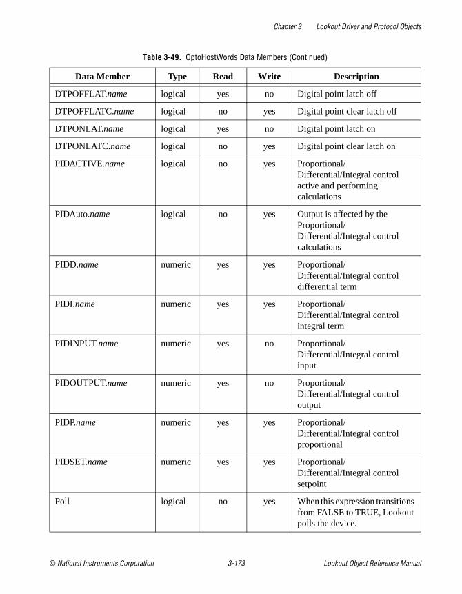
Chapter 3 Lookout Driver and Protocol Objects
© National Instruments Corporation 3-173 Lookout Object Reference Manual
DTPOFFLAT.name logical yes no Digital point latch off
DTPOFFLATC.name logical no yes Digital point clear latch off
DTPONLAT.name logical yes no Digital point latch on
DTPONLATC.name logical no yes Digital point clear latch on
PIDACTIVE.name logical no yes Proportional/ Differential/Integral control active and performing calculations
PIDAuto.name logical no yes Output is affected by the Proportional/ Differential/Integral control calculations
PIDD.name numeric yes yes Proportional/ Differential/Integral control differential term
PIDI.name numeric yes yes Proportional/ Differential/Integral control integral term
PIDINPUT.name numeric yes no Proportional/ Differential/Integral control input
PIDOUTPUT.name numeric yes no Proportional/ Differential/Integral control output
PIDP.name numeric yes yes Proportional/ Differential/Integral control proportional
PIDSET.name numeric yes yes Proportional/ Differential/Integral control setpoint
Poll logical no yes When this expression transitions from FALSE to TRUE, Lookout polls the device.
Table 3-49. OptoHostWords Data Members (Continued)
Data Member Type Read Write Description
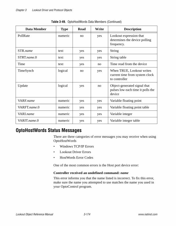
Chapter 3 Lookout Driver and Protocol Objects
Lookout Object Reference Manual 3-174 www.natinst.com
OptoHostWords Status MessagesThere are three categories of error messages you may receive when using OptoHostWords
• Windows TCP/IP Errors
• Lookout Driver Errors
• HostWords Error Codes
One of the most common errors is the Host port device error:
Controller received an undefined command: name
This error informs you that the name listed is incorrect. To fix this error, make sure the name you attempted to use matches the name you used in your OptoControl program.
PollRate numeric no yes Lookout expression that determines the device polling frequency.
STR.name text yes yes String
STRT.name.0 text yes yes String table
Time text yes no Time read from the device
TimeSynch logical no yes When TRUE, Lookout writes current time from system clock to controller
Update logical yes no Object-generated signal that pulses low each time it polls the device
VARF.name numeric yes yes Variable floating point
VARFT.name.0 numeric yes yes Variable floating point table
VARI.name numeric yes yes Variable integer
VARIT.name.0 numeric yes yes Variable integer table
Table 3-49. OptoHostWords Data Members (Continued)
Data Member Type Read Write Description

Chapter 3 Lookout Driver and Protocol Objects
© National Instruments Corporation 3-175 Lookout Object Reference Manual
OptoHostwords TCP/IP ErrorsSocket Communications error
This error message returns one of the standard Windows socket errors:
Socket timed out while attempting to connectNo Response from socketUnknown socket errorCannot resolve IP addressCannot resolve port
Lookout Driver Errors with OptoHostWordsGarbled or unexpected response
This error can happen in Ethernet or serial communications. This error means the driver received a message it could not make sense of.
No response
This error means that a serial device has not responded at all.
HostWords ErrorsThe following General, Host Port Device, Ethernet, and HostWords errors are the most common error codes encountered when using the Lookout OptoHostWords driver. For a complete list of HostWords errors, or more detailed explanations, consult your HostWords documentation.
One of the most common errors is the Host port device error:
Controller received an undefined command: name
This error informs you that the name listed is incorrect. To fix this error, make sure the name you attempted to use matches the name you configured under HostWords
Invalid port number
This indicates your have sent a peer message to the same controller, or have encountered a firmware error.
Send timeout
You may have to increase your port timeout delay. This error can also result from lending long strings to a serial port, CTS low on a host port, or a firmware error.

Chapter 3 Lookout Driver and Protocol Objects
Lookout Object Reference Manual 3-176 www.natinst.com
Bad table index
You may have a negative table index value, or an index value greater than the table length.
Numeric overflow
The result of the calculation is larger than the numeric type used.
Not a number
A math operation has resulted in a complex or imaginary number.
Divide by zero
A math operation has tried to divide by zero.
Bus fault
This indicates either a failure in the controller hardware, or an attempt to access invalid memory area.
Port already in use
This indicates an attempt to have more than one port open in a chart.
Invalid event/reaction hold buffer
This indicates an attempt to read an event/reaction data hold buffer for an event/reaction that was not configured with a read and hold reaction.
Host port relock
An error occurring after an unlock command.
String to short to hold data
You may have had a string variable too short for the data specified, or attempted to put the date or time in a string with a length of less than eight.
Wrong object type
You may have passed the wrong data type to the ENABLE and DISABLE commands.
Controller received an undefined command
Check your use of the name returned by the error message. Names must match those you configured in your OptoControl configuration.
Controller received a message with a bad CRC
This indicates a problem in communication between your PC and the controller. See the HostWords documentation for a more detailed explanation.
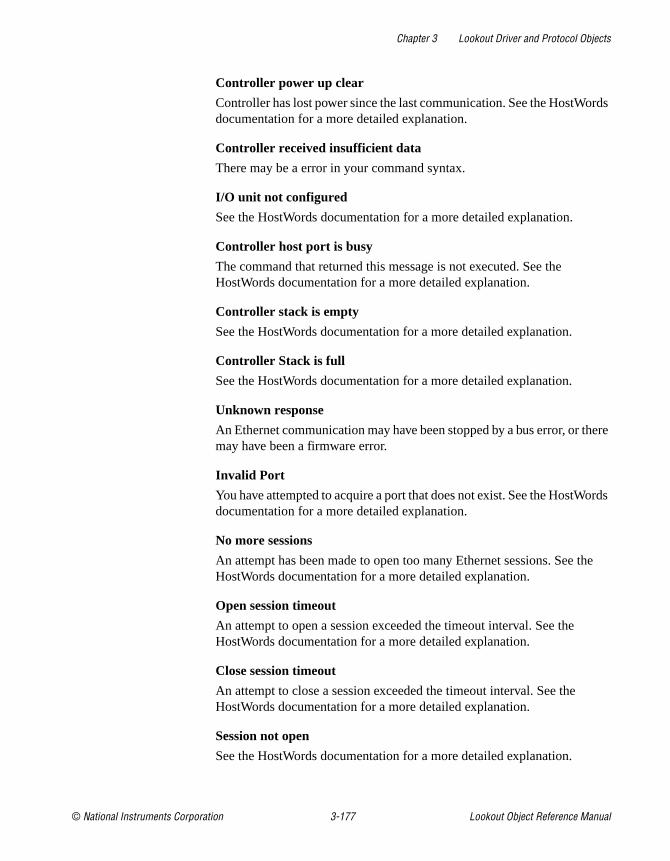
Chapter 3 Lookout Driver and Protocol Objects
© National Instruments Corporation 3-177 Lookout Object Reference Manual
Controller power up clear
Controller has lost power since the last communication. See the HostWords documentation for a more detailed explanation.
Controller received insufficient data
There may be a error in your command syntax.
I/O unit not configured
See the HostWords documentation for a more detailed explanation.
Controller host port is busy
The command that returned this message is not executed. See the HostWords documentation for a more detailed explanation.
Controller stack is empty
See the HostWords documentation for a more detailed explanation.
Controller Stack is full
See the HostWords documentation for a more detailed explanation.
Unknown response
An Ethernet communication may have been stopped by a bus error, or there may have been a firmware error.
Invalid Port
You have attempted to acquire a port that does not exist. See the HostWords documentation for a more detailed explanation.
No more sessions
An attempt has been made to open too many Ethernet sessions. See the HostWords documentation for a more detailed explanation.
Open session timeout
An attempt to open a session exceeded the timeout interval. See the HostWords documentation for a more detailed explanation.
Close session timeout
An attempt to close a session exceeded the timeout interval. See the HostWords documentation for a more detailed explanation.
Session not open
See the HostWords documentation for a more detailed explanation.
Chapter 3 Lookout Driver and Protocol Objects
Lookout Object Reference Manual 3-178 www.natinst.com
Invalid Session number
See the HostWords documentation for a more detailed explanation.
No session selected
There is no active session for the specified port.
Wrong LC type
A command has been used that is the wrong type for the current controller.
Bad Address
See the HostWords documentation for a more detailed explanation.
Operation failed
Could not gain access to the PC bus. See the HostWords documentation for a more detailed explanation.
Character not found
The Find Character in String command could not find the specified character.
Substring not found
The Find Substring in String command could not find the specified substring.
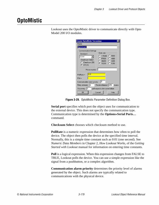
Chapter 3 Lookout Driver and Protocol Objects
© National Instruments Corporation 3-179 Lookout Object Reference Manual
OptoMisticLookout uses the OptoMistic driver to communicate directly with Opto Model 200 I/O modules.
Figure 3-29. OptoMistic Parameter Definition Dialog Box.
Serial port specifies which port the object uses for communication to the external device. This does not specify the communication type. Communication type is determined by the Options»Serial Ports… command.
Checksum Select chooses which checksum method to use.
PollRate is a numeric expression that determines how often to poll the device. The object then polls the device at the specified time interval. Normally, this is a simple time constant such as 0:01 (one second). See Numeric Data Members in Chapter 2, How Lookout Works, of the Getting Started with Lookout manual for information on entering time constants.
Poll is a logical expression. When this expression changes from FALSE to TRUE, Lookout polls the device. You can use a simple expression like the signal from a pushbutton, or a complex algorithm.
Communication alarm priority determines the priority level of alarms generated by the object. Such alarms are typically related to communications with the physical device.
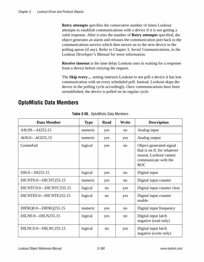
Chapter 3 Lookout Driver and Protocol Objects
Lookout Object Reference Manual 3-180 www.natinst.com
Retry attempts specifies the consecutive number of times Lookout attempts to establish communications with a device if it is not getting a valid response. After it tries the number of Retry attempts specified, the object generates an alarm and releases the communication port back to the communications service which then moves on to the next device in the polling queue (if any). Refer to Chapter 3, Serial Communications, in the Lookout Developer’s Manual for more information.
Receive timeout is the time delay Lookout uses in waiting for a response from a device before retrying the request.
The Skip every… setting instructs Lookout to not poll a device it has lost communication with on every scheduled poll. Instead, Lookout skips the device in the polling cycle accordingly. Once communications have been reestablished, the device is polled on its regular cycle.
OptoMistic Data Members
Table 3-50. OptoMistic Data Members
Data Member Type Read Write Description
AI0.09—AI255.15 numeric yes no Analog input
AO0.0—AO255.15 numeric yes yes Analog output
CommFail logical yes no Object-generated signal that is on if, for whatever reason, Lookout cannot communicate with the ROC
DI0.0—DI255.15 logical yes no Digital input
DICNT0.0—DICNT255.15 numeric yes no Digital input counter
DICNTC0.0—DICNTC255.15 logical no yes Digital input counter clear
DICNTE0.0—DICNTE255.15 logical no yes Digital input counter enable
DIFRQ0.0—DIFRQ255.15 numeric yes no Digital input frequency
DILN0.0—DILN255.15 logical yes no Digital input latch negative (read only)
DILNC0.0—DILNC255.15 logical no yes Digital input latch negative (write only)

Chapter 3 Lookout Driver and Protocol Objects
© National Instruments Corporation 3-181 Lookout Object Reference Manual
DILP0.0—DILP255.15 logical yes no Digital input latch positive (read only)
DILPC0.0—DILPC255.15 logical no yes Digital input latch positive (write only)
DIOFFP0.0—DIOFFP255.15 numeric yes no Digital input OFF pulse totalizer
DIOFFPC0.0—DIOFFFPC255.15 logical no yes Digital input OFF pulse totalizer clear
DIONP0.0—DIONP255.15 numeric yes no Digital input ON pulse totalizer
DIONP0.0—DIONP255.15 logical no yes Digital input ON pulse totalizer clear
DIPRD0.0—DIPRD255.15 numeric yes no Digital input period
DIPRDC0.0—DIPRDC255.15 logical no yes Digital Input period clear
DO0.0—DO255.15 logical yes yes Digital Output
Offhook logical no yes When TRUE, this flag instructs the object to retain exclusive use of its assigned communication port.
Poll logical no yes When this value transitions from FALSE to TRUE, Lookout polls the device.
PollRate numeric no yes Lookout expression that determines the device polling frequency
Update logical yes no Object-generated signal that pulses low each time it polls the device
Table 3-50. OptoMistic Data Members (Continued)
Data Member Type Read Write Description

Chapter 3 Lookout Driver and Protocol Objects
Lookout Object Reference Manual 3-182 www.natinst.com
OptoMistic Error MessagesNo Response within timeout periodMessage GarbledUnexpected data response lengthResponse too shortNo response (configuring)
Each of these messages indicates a communications error. See your OptoMistic documentation for more detailed information.
Mistic Error: Undefined command
Recheck your OptoMistic address. See your OptoMistic documentation for more detailed information.
Mistic Error: Checksum or CRC error
This message indicates a general COM error. See your OptoMistic documentation for more detailed information.
Mistic Error: Power-up clear error
This error message may include a code detailing more specific information. See your OptoMistic documentation for more detailed information.
Mistic Error: Communications link watchdog timeout error
This message may indicate an address problem. See your OptoMistic documentation for more detailed information.
Mistic Error: Busy error
The system was busy and did not return data.
Mistic Error: Invalid module type error
The driver has attempted to read a module of a type different than the module located at the address.

Chapter 3 Lookout Driver and Protocol Objects
© National Instruments Corporation 3-183 Lookout Object Reference Manual
OptomuxOptomux is a protocol driver class Lookout uses to communicate with Opto 22 I/O devices and other equipment using the Optomux communication protocol.
This protocol driver uses Optomux 2-pass protocol with no parity, eight data bits, and one stop bit. You can choose between CRC16 and BCC error correction modes, and select a data rate.
Several physical Optomux devices can be daisy-chained or multidropped on one ASCII network. In Lookout, you create a single Optomux object to represent all devices connected to the same COM port.
An Optomux object contains a great deal of data. It represents all devices and their associated channels. It supports reading and writing of all predefined data point types including analog input, discrete input, analog output, discrete output, counter, latch, latch clear, and temperature. When you create an Optomux object, you have immediate access to all the object data members (see data member list in Table 3-51).
Figure 3-30. Optomux Definition Parameters Dialog Box
Serial port specifies which COM port the object uses for communicating to the external device. This does not specify the communication type. Communication type is determined by the Options»Serial Ports… command.

Chapter 3 Lookout Driver and Protocol Objects
Lookout Object Reference Manual 3-184 www.natinst.com
Protocol Select specifies the type of error correction mode used by the RTU. Enhanced mode uses CRC16 error checking. Standard mode uses BCC (horizontal parity). Enhanced mode is the default and is recommended.
Data rate indicates the baud rate that Lookout uses to communicate with the hardware device. This setting should match the selection made on the physical device.
Phone number specifies the number to be dialed if the selected serial port is configured for dial-up. This number only applies to the individual protocol object.
PollRate is a numeric expression that determines how often to poll the device. The object then polls the device at the specified time interval. Normally, this is a simple time constant such as 0:01 (one second). See Numeric Data Members in Chapter 2, How Lookout Works, of the Getting Started with Lookout manual for information on entering time constants.
Poll is a logical expression. When this expression changes from FALSE to TRUE, Lookout polls the device. You can use a simple expression like the signal from a pushbutton, or a complex algorithm.
Communication alarm priority determines the priority level of alarms generated by the Optomux object. Such alarms are typically related to communications with the physical device.
Retry attempts specifies the consecutive number of times Lookout attempts to establish communications with a device if it is not getting a valid response. After it tries the number of Retry attempts specified, the Optomux object generates an alarm and releases the communication port back to the communications subsystem, which then moves on to the next device in the polling queue (if any). Refer to Chapter 3, Serial Communications, in the Lookout Developer’s Manual for more information.
Receive timeout is the time delay Lookout uses in waiting for a response from a device before retrying the request.
The Skip every… setting instructs Lookout to not poll a device it has lost communication with on every scheduled poll. Instead, Lookout skips the device in the polling cycle accordingly. Once communications have been reestablished, the device is polled on its regular cycle.
Chapter 3 Lookout Driver and Protocol Objects
© National Instruments Corporation 3-185 Lookout Object Reference Manual
Optomux Watchdog CapabilityThe Optomux protocol has a built in watchdog capability. The device monitors communications at all times. If the device receives no communications within the amount of time specified by WDTime, the device goes into watchdog state. This state makes sure all your devices are in a fail-safe condition if there is any kind of COM failure.
The DWD and AWD data members write to the device the values that device will use if it enters the watchdog state. They are write only.
Notice that the DWD data members are not logical values, as you might expect them to be. They also do not have channel numbers. This is because you set the watchdog data of an entire discrete module with one command and one value. Because there may be 16 channels possible, the single value sent may be as large as 16-bit.
For example, if you want to set the watchdog data for the discrete output module (DWD) at address 3, perform the following steps:
1. Connect a numeric value, such as 10 seconds, to WDTime. There has to be something connected to data member or you cannot set watchdog data. WDTime reads the numeric input as milliseconds; to set the watchdog time to 10 seconds, the numeric input must be 10000.
2. If you want Channels 1, 2, and 16 to be ON when the device goes into watchdog state, and all other channels to be OFF, send the hex value 0x8003 to DWD3. This expands to 1000 0000 0000 0011 in binary (Optomux arranges channels from left to right in the binary sequence). You can use the Change»Numeric Format... option to create a hexadecimal numeric in Lookout.
AWD data members work the same way, except that you have a separate data member for each channel, and you give it a numeric value. To set channel 3 of the analog output module at address 10, you would connect the numeric value to AWD10.3.

Chapter 3 Lookout Driver and Protocol Objects
Lookout Object Reference Manual 3-186 www.natinst.com
Optomux Data MembersAs with all Lookout drivers, you can access I/O points and other data through data members. The following is a table of data members currently supported by the Optomux object class.
Table 3-51. Optomux Data Members
Data Member Type Read Write Description
AI0.1 – AI255.16 numeric yes no Analog input. 12 bit word containing an unsigned integer ranging from 0 to 4095
AO0.1 – AO255.16 numeric yes yes Analog output. 12 bit word containing an unsigned integer ranging from 0 to 4095
AWD0.1 – AWD255.16 numeric no yes Analog watchdog data
CNT0.1 – CNT255.16 numeric yes no Counter. Returns accumulated count for specified inputs
CommFail logical yes no Object-generated signal that is on if, for whatever reason, Lookout cannot communicate with the device(s)
DI0.1 – DI255.16 logical yes no Discrete input
DO0.1 – DO255.16 logical yes yes Discrete output
DWD0 – DWD255 numeric no yes Discrete watchdog data
LAT0.1 – LAT255.16 logical yes no Returns ON status for inputs which are latched
LTC0.1 – LTC255.16 logical yes no Returns ON status for latched input and clears the latch
Update logical yes no Object-generated signal that pulses low each time it polls the device
WDtime numeric no yes Watchdog time (in ms)

Chapter 3 Lookout Driver and Protocol Objects
© National Instruments Corporation 3-187 Lookout Object Reference Manual
Comments To specify the address of an analog input located on channel 4 of module 3, you would enter AI3.4 , where
Note The Optomux protocol may perform limited value-type verifications depending upon the hardware you use. In other words, trying to read analog input data from a discrete module may be allowed but the data returned may be arbitrary (or zero).
Optomux Status MessagesNo response within timeout period
Lookout received no response from a device within the Receive timeout period. The Optomux object is able to use the COM port, but when it polls the device, it does not respond—as if it is not even there. If you have daisy-chained several devices, you have introduced an inherent delay. You may have to significantly increase Receive timeout (and Poll Rate) to ensure Lookout is allowing enough time to receive the expected response. This increase has nothing to do with the processing capabilities of Lookout. Rather it is based solely on Data rate and the number of devices on the chain. Also, verify your baud rate settings, cable connections, power, configuration settings, COM port settings, and polling addresses.
Invalid data request from module
Either you tried to read from a module that is missing, or you attempted a data type mismatch. For example, you may have tried to read a discrete value from an analog module. This data type mismatch is seen on a data analyzer as a frame containing question marks. This may be an addressing problem. Verify that the type of I/O at the desired channel matches the signal type of the address identified in the data member you are writing to.
Message garbled – Bad CRC or BCC
The Optomux object is receiving a poll response from the device(s), but it could not decipher the response. Verify that the error correction scheme you selected in Protocol Select is the same as that of all of the physical devices. Also verify that all devices connected to the COM port have unique addresses. It may also be that the last part of the message is getting clipped off before it is completed. Consider increasing the number of Retry
AI 3 . 4
Signal type
Module Number or address
Channel number

Chapter 3 Lookout Driver and Protocol Objects
Lookout Object Reference Manual 3-188 www.natinst.com
attempts. You may have to increase the Receive gap Serial Port setting to ensure Lookout is receiving the entire message. If your Serial Port is configured for radio this could be caused by an audible squelch tail occurring at the end of a radio transmission. You may need to adjust the RTS delay off or the CTS timeout settings.
Unexpected data response length
The Optomux object is receiving a poll response from the device(s), but the response is too long. Verify that all devices connected to the COM port have unique addresses. Devices with identical addresses may be trying to respond at the same time.
Response too short
The Optomux object is receiving data that does not meet the minimum frame length requirements. This could happen if you configured a device for 4-pass instead of 2-pass protocol. Lookout uses 2-pass protocol. Verify device protocol settings.

Chapter 3 Lookout Driver and Protocol Objects
© National Instruments Corporation 3-189 Lookout Object Reference Manual
PhilipsPhilips is a protocol driver class Lookout uses to communicate with Philips devices using the PPCCOMM communication protocol.
A Philips object contains a great deal of data. It supports reading and writing of all predefined data points. When you create a Philips object, you have immediate access to all the object data members (see Philips Data Members list in this section).
Figure 3-31. Philips Configuration Parameters Dialog Box
Serial port specifies which communications port the object uses for communicating to the external device. This does not specify the communication type. Communication type is determined by the Options»Serial Ports… command.
Baud rate indicates the baud rate that Lookout uses to communicate with the hardware device. This setting should match the selection made on the physical device.
Data bits indicates the number of data bits that Lookout uses to communicate with the hardware device. This setting should match the selection made on the physical device.

Chapter 3 Lookout Driver and Protocol Objects
Lookout Object Reference Manual 3-190 www.natinst.com
Stop bits indicates the number of stop bits that Lookout uses to communicate with the hardware device. This setting should match the selection made on the physical device.
Parity indicates the parity that Lookout uses to communicate with the hardware device. This setting should match the selection made on the physical device.
Phone number specifies the number to be dialed if the selected serial port is configured for dial-up. This number only applies to the individual protocol object.
PollRate is a numeric expression that determines how often to poll the device. The object then polls the device at the specified time interval. Normally, this is a simple time constant such as 0:01 (one second). See Numeric Data Members in Chapter 2, How Lookout Works, of the Getting Started with Lookout manual for information on entering time constants.
Poll is a logical expression. When this expression changes from FALSE to TRUE, Lookout polls the device. You can use a simple expression like the signal from a pushbutton, or a complex algorithm.
Communication alarm priority determines the priority level of alarms generated by the Philips object. Such alarms are typically related to communications with the physical device.
Retry attempts specifies the consecutive number of times Lookout attempts to establish communications with a device if it is not getting a valid response. After it tries the number of Retry attempts specified, the Philips object generates an alarm and releases the communication port back to the communications service which then moves on to the next device in the polling queue (if any). Refer to Chapter 3, Serial Communications, in the Lookout Developer’s Manual for more information.
Receive timeout is the time delay Lookout uses in waiting for a response from a device before retrying the request.
The Skip every… setting instructs Lookout not to poll a device it has lost communication with on every scheduled poll. Instead, Lookout skips the device in the polling cycle accordingly. Once communications have been reestablished, the device is polled on its regular cycle.

Chapter 3 Lookout Driver and Protocol Objects
© National Instruments Corporation 3-191 Lookout Object Reference Manual
Philips Data MembersAs with all Lookout drivers, you can access I/O points and other data through data members. The following is a table of data members currently supported by the Philips object class.
Table 3-52. Philips Data Members
Data Member Type Read Write Description
CommFail logical yes no Object-generated signal that is on if Lookout cannot communicate with the device(s)
IB0.0 – IB1023.1 numeric yes yes Discrete inputs, 8 bits
ID0 – ID1023 numeric yes yes Discrete inputs, 32 bits
IW0 – IW1023 numeric yes yes Discrete inputs, 16 bits
IX0.0 – IX123.15 logical yes no Discrete input, 1 bit
MB0.0 – M14335.1 numeric yes yes Data register, 8 bits
MD0 – MD14335 numeric yes yes Data register, 32 bits
MW0 – MW14335 numeric yes yes Data register, 16 bits
MX0.0 – MX14335.15 logical yes no Data register, 1 bit
Poll logical no yes When this value transitions from FALSE to TRUE, Lookout polls the device.
PollRate numeric no yes Lookout expression that determines the device polling frequency.
QB0.0 – QB1023.1 numeric yes yes Discrete outputs, 8 bits
QD0 – QD1023 numeric yes yes Discrete outputs, 32 bits
QW0 – QW1023 numeric yes yes Discrete outputs, 16 bits
QX0.0 – QX1023.15 logical yes no Discrete output, 1 bit
Update logical yes no Object-generated signal that pulses low each time it polls the device.

Chapter 3 Lookout Driver and Protocol Objects
Lookout Object Reference Manual 3-192 www.natinst.com
Philips Status MessagesInvalid frame formatBad ChecksumInvalid frame length
These messages indicate garbled communications. Check cabling for signal noise or multiple devices with the same address.
Philips AlarmsThese are messages returned to Lookout in a response frame. See your Philips documentation for meanings and solutions.

Chapter 3 Lookout Driver and Protocol Objects
© National Instruments Corporation 3-193 Lookout Object Reference Manual
Profibus DPProfibus DP is a protocol driver class for communicating with PLCs and remote I/O units using the Decentralized Periphery protocol in the Profibus standard. The Lookout driver currently supports the S-S Technologies card 5136-PFB PC card only.
Configuring the Profibus DP NetworkIn order to use the Lookout Profibus DP driver for the S-S card, you must first configure your DP network using the Siemens COM ET-200 software. This software is not included in the Lookout release and must be purchased separately. The S-S card is the master device on the Profibus network. Because the COM ET-200 software does not know about this device, you must select some other device as the master. You may leave all of its parameters as the defaults because the S-S card ignores the parameters of this master system.
You must, however, enter a master station number and configure the bus parameters. These parameters are used by the SS card to configure the DP network.
Next, you must configure the parameters for each of the slave devices. Refer to the online documentation for the COM ET200 software for instructions on how to do this. Once all the slave devices are configured, save the file to an .et2 format and export the file to a binary file .2bf
format. This last step is done using the Export selection in the File menu. Place the binary file in a location accessible to Lookout.
Profibus DP RequirementsTo run the 32-bit version of this object, you must be running Windows NT 3.51 or greater or Windows 95, with an S-S Technologies 5136-PFB card installed in the computer. Lookout automatically loads the firmware module when an object is created.
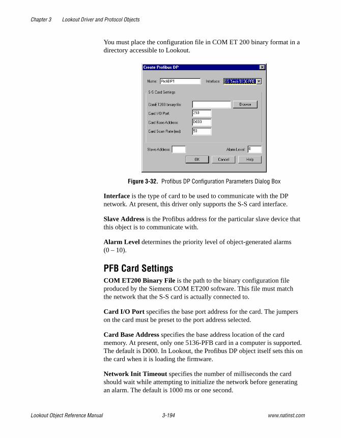
Chapter 3 Lookout Driver and Protocol Objects
Lookout Object Reference Manual 3-194 www.natinst.com
You must place the configuration file in COM ET 200 binary format in a directory accessible to Lookout.
Figure 3-32. Profibus DP Configuration Parameters Dialog Box
Interface is the type of card to be used to communicate with the DP network. At present, this driver only supports the S-S card interface.
Slave Address is the Profibus address for the particular slave device that this object is to communicate with.
Alarm Level determines the priority level of object-generated alarms (0 – 10).
PFB Card SettingsCOM ET200 Binary File is the path to the binary configuration file produced by the Siemens COM ET200 software. This file must match the network that the S-S card is actually connected to.
Card I/O Port specifies the base port address for the card. The jumpers on the card must be preset to the port address selected.
Card Base Address specifies the base address location of the card memory. At present, only one 5136-PFB card in a computer is supported. The default is D000. In Lookout, the Profibus DP object itself sets this on the card when it is loading the firmware.
Network Init Timeout specifies the number of milliseconds the card should wait while attempting to initialize the network before generating an alarm. The default is 1000 ms or one second.

Chapter 3 Lookout Driver and Protocol Objects
© National Instruments Corporation 3-195 Lookout Object Reference Manual
Card Scan Rate is the rate at which the 5136-PFB card is scanned to look for fresh data. The default is 50 milliseconds.
Profibus DP Data MembersAll readable and writable members—inputs/outputs—are bundled with the object. Therefore, as soon as you create a Profibus DP object you immediately have access to all the object data members.
Data can be addressed either as bytes or words within slots, or as bits within these bytes or words. However, you cannot address a slot configured for digital input or output (as bytes) using word numbers. Similarly you cannot address a slot configured for analog input or output (as words) using byte numbers.
Table 3-53. Profibus DP Data Members
Data Member Type Read Write Description
CommFail logical yes no Object-generated signal that is on if, for any reason, Lookout cannot communicate with the Profibus card.
Slot0B0 – Slot127B63 numeric yes yes This addresses data in a slot as a sequence of bytes.
Slot0B0.0 – Slot127B63.7
logical yes yes This addresses individual bits while looking at a slot as a sequence of bytes.
Slot0W0 – Slot127W63 numeric yes yes This addresses data in a slot as a sequence of words.
Slot0W0.0 – Slot127W63.15
logical yes yes This addresses individual bits while looking at a slot as a sequence of words.

Chapter 3 Lookout Driver and Protocol Objects
Lookout Object Reference Manual 3-196 www.natinst.com
Profibus DP Status MessagesProfibus SS Card not found
The SS card was not found at the specified port and card base address. Check that the jumper settings on your card match the port address that you specified in the object creation dialog box. Also, check that the card is properly seated in the slot.
Profibus init failed
The initialization of the Profibus SS card failed. This alarm is usually followed by an explanation of the reason for this failure.
Error accessing COM ET 200 binary file
A file error occurred while attempting to open the COM ET 200 binary file.
Unconfigured Read Error
A read was attempted on a data member that is not valid in the current Profibus DP network configuration.
Unconfigured Write Error
A write was attempted on a data member that is not valid in the current Profibus DP network configuration.
Slave Error
There was a problem with the particular slave device you are trying to access. This alarm is followed by a description of the problem with that slave device.

Chapter 3 Lookout Driver and Protocol Objects
© National Instruments Corporation 3-197 Lookout Object Reference Manual
ProfibusL2ProfibusL2 is a protocol driver class for communicating with PLCs using Profibus Sinec-L2.
One of the problems with communicating with PLCs using Profibus Sinec-L2 is that there is no standard messaging system for transferring data. The Sinec L2 interface has a variety of message types available that you can use with applications as well as PLCs on a network. Lookout uses its own messaging system for transferring data and provides help for you to implement the PLC end of the messaging system.
Lookout Messaging SystemYou should read the Siemens manual Sinec-L2 Interface of the S5-95U Programmable Controller, or some similar document that details a Sinec-L2 interface and how to write programs for your particular Sinec-L2 interface device.
Lookout uses two message types to receive and send all the data it needs. It uses the message type SRDh (Send and Request Data, high priority) to receive data from the PLC. To send data to the PLC, Lookout uses the message type SDAh (Send Data with Acknowledge, high priority).
All messages in Sinec-L2 are directed at specified SAPs (Service Access Points). You must program SAPs on each PLC to provide or accept the data you want to exchange with Lookout. You can use a given SAP only for reading or writing. Each poll request for a configured SAP reads all the data in that SAP. In the same way, if you are writing to a particular SAP, each write transfers all the data for that SAP to the PLC.
Sample ProgramIncluded in your copy of Lookout is a sample Siemens STEP5 program file, LKTPFBST.S5D. This file is placed in the \sinecl2 directory under your Lookout directory during installation. This program contains an example of the logic necessary to create the Service Access Points (SAPs) for communications from a Simatic S5-95U to Lookout software using the Profibus protocol.
The program consists of one program block, three function blocks, three data blocks, and the modifications needed in OB1 and DB1 to successfully configure the Profibus communication link. This sample establishes two SAPs to the Profibus Layer 2 services of the PLC. Lookout uses the first

Chapter 3 Lookout Driver and Protocol Objects
Lookout Object Reference Manual 3-198 www.natinst.com
SAP, 34, to write values to the PLC. Lookout uses the second SAP, 35, when reading values from the PLC. You can read or write data in byte, word, or double word formats.
In order to install the example Profibus program, follow these steps:
1. TRANSFER ALL BLOCKS TO THE CPU MEMORY
This must include all PBs, FBs, and DBs.
2. PROFIBUS CONFIGURATION
The example configures SAP 34 and SAP 35. However, you may modify the program, if necessary, to customize your application.
3. PROFIBUS EXECUTION
Jump to PB 223 is required from OB1. An example of this jump is included in OB1 in the program.
4. PROFIBUS DATA HANDLING
The sample program uses DB 234, DB 235, and DB 236 to move data from the PLC to Lookout and from Lookout to the PLC. All data must be mapped to and from data blocks for Profibus communications. These data blocks also contain 8-byte headers used as a part of the Profibus configuration parameters. Again, you may modify these blocks if necessary. In addition, flag bytes above 200 are used by the example program, so you should avoid using them.
Detailed Explanation of the Profibus Example ProgramThe example program employs the Layer 2 services of the Siemens Simatic S5-95U for the Profibus communications to Lookout. In particular, the program uses SRD and RUP_MULTIPLE. The configuration of these services is described in detail in Chapter 8, Data Transmission by Accessing Layer 2 Services, of the Sinec-L2 Interface of the S5-95U Programmable Controller Manual.
DB1 ConfigurationThe first step in configuring the S5-95U is to insert the correct Profibus parameters in DB1 of the PLC. You should employ the COM_DB1 software, available from Siemens, when setting these parameters.
First, you must enter the SINEC L2 basic parameters. These parameters include the station address, baud rate, target rotation time, and more. The parameters must exactly match those used in configuring your SinecL2 object. You can find the defaults for these parameters in the example program where they are used.

Chapter 3 Lookout Driver and Protocol Objects
© National Instruments Corporation 3-199 Lookout Object Reference Manual
Next you must configure the SINEC L2 layer 2 service. Here, you define the individual SAPs and designate a status byte for each SAP. SAPs used for writing data to the PLC must have a status byte allocated in the Receive area. SAPs used for reading data from the PLC must have a status byte allocated in both the Send and Receive areas.
You can define up to 23 SAPs, numbering from 33 to 54 and also including 64. The example program uses SAP 34 for writing data, and FW 204 as its status and length bytes. The program uses SAP 35 for reading data, with FW 200 and FW 202 used for the status and length bytes in the Send and Receive areas.
Function Block ExplanationThe example program contains three function blocks to handle the data transfer between the Profibus SAPs and the CPU internal memory. These blocks evaluate the status bits associated with each SAP, and send or receive the data when allowable.
Function Block FB 224 coordinates the data written from Lookout to the PLC. The CPU looks for an indication from the SAP that new data exists. If the receive is viable, the block performs a jump to FB 253, which is the integrated L2-REC function block. The block takes the data and writes it to the area specified by DBNR. The example uses DB 234, starting at DW 0 and continuing for an unknown wildcard length. The first 8 bytes of DB 234, DW 0 through DW 3, contain the header for the message. You must include this header in the data block for proper operation.
Function Blocks FB 223 and FB 225 handle the data Lookout is attempting to read from the PLC. FB 225 acts in the same way as FB 224, looking for an indication that the SAP has received a new request for data. FB 223 actually writes the data to the SAP using a jump to FB 252, the integrated L2-SEND function block. The data is taken from the area designated by DBNR. In this case, DB 235 is used by FB 223 and DB 236 is used by FB 225. The first 8 bytes act as a header to the message to follow, and must be set with specific parameters. In DB 235, DW 1 through DW 4 are used for the Send, and DW 128 through DW 131 are used for the Indication. In DB 236, DW 1 through DW 4 are used for the Indication. The parameters required in the data blocks are discussed in the Sinec-L2 Interface of the S5-95U Programmable Controller Manual.
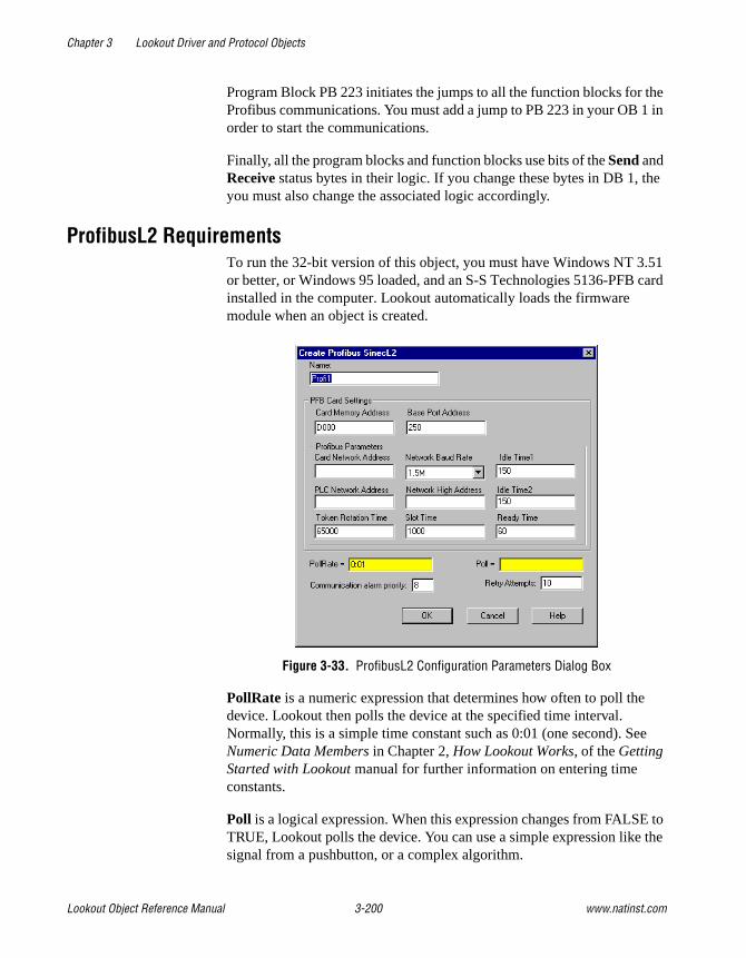
Chapter 3 Lookout Driver and Protocol Objects
Lookout Object Reference Manual 3-200 www.natinst.com
Program Block PB 223 initiates the jumps to all the function blocks for the Profibus communications. You must add a jump to PB 223 in your OB 1 in order to start the communications.
Finally, all the program blocks and function blocks use bits of the Send and Receive status bytes in their logic. If you change these bytes in DB 1, the you must also change the associated logic accordingly.
ProfibusL2 RequirementsTo run the 32-bit version of this object, you must have Windows NT 3.51 or better, or Windows 95 loaded, and an S-S Technologies 5136-PFB card installed in the computer. Lookout automatically loads the firmware module when an object is created.
Figure 3-33. ProfibusL2 Configuration Parameters Dialog Box
PollRate is a numeric expression that determines how often to poll the device. Lookout then polls the device at the specified time interval. Normally, this is a simple time constant such as 0:01 (one second). See Numeric Data Members in Chapter 2, How Lookout Works, of the Getting Started with Lookout manual for further information on entering time constants.
Poll is a logical expression. When this expression changes from FALSE to TRUE, Lookout polls the device. You can use a simple expression like the signal from a pushbutton, or a complex algorithm.

Chapter 3 Lookout Driver and Protocol Objects
© National Instruments Corporation 3-201 Lookout Object Reference Manual
Communication alarm priority determines the priority level of object-generated alarms (0 – 10).
Retry attempts specifies the consecutive number of times Lookout attempts to establish communications with a device if it is not getting a valid response. After it tries the number of Retry attempts specified, the Profibus L2 object generates an alarm.
Card Memory Address specifies the base address location of the card memory. At present, only one 5136-PFB card in a computer is supported. The default is D000. In Lookout, the Profibus object itself sets this on the card when it is loading the firmware.
Base Port Address specifies the base port address for the card. The jumpers on the card must be preset to the port address selected.
PFB Card SettingsCard Network Address specifies the Profibus address for the card on the bus. The valid range is 0 to 126.
PLC Network Address specifies the Profibus address for the PLC on the bus. The valid range is 0 to 126.
Network High Address specifies the highest possible Profibus address possible on the bus. The valid range is 0 to 126.
Token Rotation Time specifies the target maximum token rotation time for the network in Tbits (bit times). The valid range is 256 to 16,777,215.
Network Baud Rate specifies the baud rate to be used on the network. The valid selections are shown in the selection box.
Slot Time specifies how long the card waits for a reply to a message, in Tbits. The valid range is 37 to 16,383.
Idle Time1 specifies the time in Tbits that the card waits after it receives a reply, an acknowledge or a token message before sending a message. Range: 35 to 1023

Chapter 3 Lookout Driver and Protocol Objects
Lookout Object Reference Manual 3-202 www.natinst.com
Idle Time2 specifies the time in Tbits that the card waits after sending an SDN (Send Data with no acknowledge) message before it sends again. Range: 35 to 1023
Ready Time specifies the time in Tbits that the card, after it sends a command, is ready to receive the ACK or response. It is also the time the card waits after receiving a command. The valid values range from 11 to 1023.
ProfibusL2 Data MembersAll readable and writable members (inputs/outputs), polling instructions, and so on, are bundled with the object. Therefore, as soon as you create a Profibus object you immediately have access to all the object data members (see data member list in Table 3-54).
Data is addressed using SAP numbers and, within a SAP, the byte, word or Dword number. For example, if SAP 33 is configured for reading, SAP33B200 refers to the 201st byte of that SAP. Similarly, SAP42DW10.20 refers to the 21st bit of the 11th Dword of SAP 42.
The legal SAPs used by the Lookout Profil2 driver range from 0 to 255. Each SAP may provide up to 242 bytes of data (0 – 241) which you can address either as bytes, 121 words, or 60 Dwords. The actual range of valid SAPs varies according to the device being addressed. You can address bits by appending a period and bit number after the byte number, word number, or Dword number.
Note Lookout protocol driver objects automatically generate an efficient read/write blocking scheme based on the inputs and outputs being used in your process file. You are not required to build your own I/O blocking table.
Table 3-54. ProfibusL2 Data Members
Data Member Type Read Write Description
CommFail logical yes no Object-generated signal that is on if, for any reason, Lookout cannot communicate with the Profibus card.
Poll logical no yes When this value transitions from FALSE to TRUE Lookout polls the device.
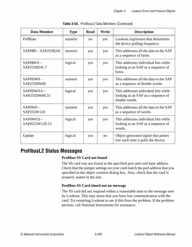
Chapter 3 Lookout Driver and Protocol Objects
© National Instruments Corporation 3-203 Lookout Object Reference Manual
ProfibusL2 Status MessagesProfibus SS Card not found
The SS card was not found at the specified port and card base address. Check that the jumper settings on your card match the port address that you specified in the object creation dialog box. Also, check that the card is properly seated in the slot.
Profibus SS Card timed out on message
The SS card did not respond within a reasonable time to the message sent by Lookout. This may mean that you have lost communication with the card. Try restarting Lookout to see if this fixes the problem. If the problem persists, call National Instruments for assistance.
PollRate numeric no yes Lookout expression that determines the device polling frequency.
SAP0B0 – SAP255B241 numeric yes yes This addresses all the data in the SAP as a sequence of bytes.
SAP0B0.0 – SAP255B241.7
logical yes yes This addresses individual bits while looking at an SAP as a sequence of bytes.
SAP0DW0 – SAP255DW60
numeric yes yes This addresses all the data in the SAP as a sequence of double words.
SAP0DW0.0 – SAP255DW60.31
logical yes yes This addresses individual bits while looking at an SAP as a sequence of double words.
SAP0W0 – SAP255W120
numeric yes yes This addresses all the data in the SAP as a sequence of words.
SAP0W0.0 – SAP0255W120.15
logical yes yes This addresses individual bits while looking at an SAP as a sequence of words.
Update logical yes no Object-generated signal that pulses low each time it polls the device.
Table 3-54. ProfibusL2 Data Members (Continued)
Data Member Type Read Write Description

Chapter 3 Lookout Driver and Protocol Objects
Lookout Object Reference Manual 3-204 www.natinst.com
RelianceReliance is a protocol driver class Lookout uses for communicating with Reliance AutoMate controllers.
Figure 3-34. Reliance Definition Parameters Dialog Box
Note If you are developing your application without a PC-Link card installed in your computer, and do not know the settings in the target system, you can enter 250 for Port Address, 0 for Node ID, and 3 for Max Nodes. You can then create the Reliance object and correct the parameter values for the actual system later, if necessary.
Interface is the method the object uses to communicate with the Reliance PLCs. Currently, only the Reliance R-Net is supported, using the Reliance PC-Link card.
PollRate is a numeric expression that determines how often to poll the device. Reliance then polls the device at the specified time interval. Normally, this is a simple time constant such as 0:01 (one second). See Numeric Data Members in Chapter 2, How Lookout Works, of the Getting Started with Lookout manual for information on entering time constants.
Poll is a logical expression. When this expression changes from FALSE to TRUE, Lookout polls the device. You can use a simple expression like the signal from a pushbutton, or a complex algorithm.
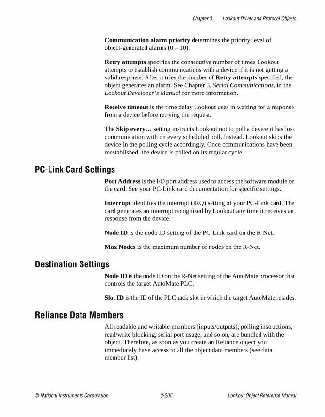
Chapter 3 Lookout Driver and Protocol Objects
© National Instruments Corporation 3-205 Lookout Object Reference Manual
Communication alarm priority determines the priority level of object-generated alarms (0 – 10).
Retry attempts specifies the consecutive number of times Lookout attempts to establish communications with a device if it is not getting a valid response. After it tries the number of Retry attempts specified, the object generates an alarm. See Chapter 3, Serial Communications, in the Lookout Developer’s Manual for more information.
Receive timeout is the time delay Lookout uses in waiting for a response from a device before retrying the request.
The Skip every… setting instructs Lookout not to poll a device it has lost communication with on every scheduled poll. Instead, Lookout skips the device in the polling cycle accordingly. Once communications have been reestablished, the device is polled on its regular cycle.
PC-Link Card SettingsPort Address is the I/O port address used to access the software module on the card. See your PC-Link card documentation for specific settings.
Interrupt identifies the interrupt (IRQ) setting of your PC-Link card. The card generates an interrupt recognized by Lookout any time it receives an response from the device.
Node ID is the node ID setting of the PC-Link card on the R-Net.
Max Nodes is the maximum number of nodes on the R-Net.
Destination SettingsNode ID is the node ID on the R-Net setting of the AutoMate processor that controls the target AutoMate PLC.
Slot ID is the ID of the PLC rack slot in which the target AutoMate resides.
Reliance Data MembersAll readable and writable members (inputs/outputs), polling instructions, read/write blocking, serial port usage, and so on, are bundled with the object. Therefore, as soon as you create an Reliance object you immediately have access to all the object data members (see data member list).

Chapter 3 Lookout Driver and Protocol Objects
Lookout Object Reference Manual 3-206 www.natinst.com
Note Lookout protocol driver objects automatically generate an efficient read/write blocking scheme based on the inputs and outputs being used in your process file. You are not required to build your own I/O blocking table.
Reliance Data Members
Reliance Status MessagesSee your Reliance or PC-Link documentation for details of Reliance device generated messages.
Table 3-55. Reliance Data Members (all addresses are in octal)
Data Member Type Read Write Description
0 – 157775 numeric yes yes 16-bit input registers encoded as unsigned binary integers ranging from 0 to 65,535.
0.0 – 15775.17 logical yes yes Access individual bits in holding registers and read them as logical ON/OFF values. The least significant bit is 1; the most significant bit is 17.
CommFail logical yes no Driver-generated signal that is ON if Lookout cannot communicate with the device.
D0 – D157774 numeric yes yes Wide data format ranges from –99,999,999 to +99,999,999.
Poll logical no yes When this expression transitions from FALSE to TRUE, Lookout polls the device.
PollRate numeric no yes Lookout expression that determines the polling frequency of the device.
Update logical yes no Driver-generated signal that pulses each time the driver polls the device.

Chapter 3 Lookout Driver and Protocol Objects
© National Instruments Corporation 3-207 Lookout Object Reference Manual
RKC F SeriesRKC is a protocol driver class Lookout uses to communicate with RKC F Series devices using 7-bit ASCII serial communications.
With this driver you can read and write to all predefined data points allowed by a particular F Series model. When you create an RKC object, you have immediate access to all the object data members. See the data member tables for more information on data members for this object.
Address specifies which RKC F Series device you are communicating with. This number is between 0 and 31, and is set on the F Series device.
PLC Model specifies what model of RKC F Series device you are using. This driver supports the following models: REX-F400, REX-F700, and REX-F900.
Serial port specifies which COM port the object uses to communicate with the external device. This does not specify the communication type. Communication type is determined by the Options»Serial Ports... command.
Data rate indicates the baud rate Lookout uses to communicate with the hardware device. This setting should match the selection made on the physical device.

Chapter 3 Lookout Driver and Protocol Objects
Lookout Object Reference Manual 3-208 www.natinst.com
Data bits indicates the number of data bits Lookout uses to communicate with the hardware device. This setting should match the selection made on the physical device.
Stop bits indicates the number of stop bits Lookout uses to communicate with the hardware device. This setting should match the selection made on the physical device.
Parity indicates the parity that Lookout uses to communicate with the hardware device. This setting should match the selection made on the physical device.
Phone number specifies the number to be dialed if the selected serial port is configured for dial-up.
PollRate is a numeric expression that determines how often to poll the device. The object then polls the device at the specified time interval. Normally, this is a simple time constant such as 0:01 (one second). See Numeric Data Members in Chapter 2, How Lookout Works, of the Getting Started with Lookout manual for information on entering time constants.
Poll is a logical expression. When this expression changes from FALSE to TRUE, Lookout polls the device. You can use a simple expression like the signal from a pushbutton, or a complex algorithm.
Communication alarm priority determines the priority level of alarms generated by the RKC object. Such alarms are typically related to communications with the physical device.
Retry attempts specifies the consecutive number of times Lookout attempts to establish communications with a device if it is not getting a valid response. After it tries the number of Retry attempts specified, the RKC object generates an alarm and releases the COM port. See Chapter 3, Serial Communications, in the Lookout Developer’s Manual for more information.
Receive timeout is the time delay Lookout uses in waiting for a response from a device before retrying the request.
The Skip every... setting instructs Lookout to not poll a device it has lost communication with on every scheduled poll. Instead, Lookout skips the device in the polling cycle. Once communications have been reestablished, the device is polled on its regular cycle.

Chapter 3 Lookout Driver and Protocol Objects
© National Instruments Corporation 3-209 Lookout Object Reference Manual
RKC Data MembersAs with all Lookout drivers, you can access I/O points and other data through data members. The Lookout RKC object class currently supports the data members contained in the following tables, which are divided into groups according to their functionality.
Note For a more complete definition of the function of these data members, see your RKC F Series documentation.
Not all data members are valid for every F Series device. See your RKC documentation for which data members are valid for particular model numbers.
Table 3-56. RKC Data Member Group
Parameter Group Description
Measured Value Group measured inputs and alarm status
Operation Mode Group operation mode status
Memory Area and Set Value Groupset value (SV)
Parameter Group 10 measured input parameters
Parameter Group 11 remote setting input parameters
Parameter Group 12 output parameters
Parameter Group 13 auto-tuning bias parameters
Parameter Group 14 alarm 1 parameters
Parameter Group 15 analog output parameters
Parameter Group 16 positioning, proportioning, PID action parameters
Parameter Group 17 bar graph parameters
Parameter Group 20 input selection parameters
Parameter Group 21 setting parameters
Parameter Group 22 output action parameters
Parameter Group 23 alarm 2 parameters
Parameter Group 40 data lock parameters
Lookout data members standard Lookout data members

Chapter 3 Lookout Driver and Protocol Objects
Lookout Object Reference Manual 3-210 www.natinst.com
Table 3-57. Measured Value Group
Data Member Type Read Write Description
AA logical yes no First alarm status
AB logical yes no Second alarm status
AC logical yes no Heater break alarm status
B1 logical yes no Burnout status
B2 logical yes no Burnout status of feedback resistance input
M1 numeric yes no Measured value input
M2 numeric yes no Feedback resistance input
M3 numeric yes no Current transformer input
MS numeric yes no Set value
O1 numeric yes no Manipulated output
O2 numeric yes no Cooling-side manipulated output
S2 numeric yes no Remote set value
Table 3-58. Operation Mode Group
Data Member Type Read Write Description
C1 logical yes yes Local/remote mode
E1 logical yes yes Local/external memory area transfer
G1 logical yes yes PID control/autotuning
J1 logical yes yes Auto/manual mode
ON numeric yes no Manipulated output
RA logical yes no Local/computer mode
SR logical yes yes RUN/STOP mode
ZA numeric yes yes Control area

Chapter 3 Lookout Driver and Protocol Objects
© National Instruments Corporation 3-211 Lookout Object Reference Manual
Table 3-59. Memory Area and Set Value Group
Data Member Type Read Write Description
A1:1 - A1:8 numeric yes yes First alarm setting
A2:1 - A2:8 numeric yes yes Second alarm setting
CA:1 - CA:8 numeric yes yes Control response designation parameter
D1:1 - D1:8 numeric yes yes Derivative constant
HH:1 - HH:8 numeric yes yes Setting change rate limit
I1:1 - I1:8 numeric yes yes Integral constant
P1:1 - P1:8 numeric yes yes Proportional constant
P2:1 - P2:8 numeric yes yes Cooling-side proportional band
S1:1 - S1:8 numeric yes yes Set value
V1:1 - V1:8 numeric yes yes Deadband
Table 3-60. Parameter Group 10 (Measured Input Parameters)
Data Member Type Read Write Description
DP numeric yes yes Low input cut-off
F1 numeric yes yes Measured value first order lag filter
PB numeric yes yes Measured value bias
Table 3-61. Parameter Group 11(Remote Setting Input Parameters)
Data Member Type Read Write Description
F2 numeric yes yes Remote set value first order lag filter
RB numeric yes yes Remote set value bias
RR numeric yes yes Remote set value ratio

Chapter 3 Lookout Driver and Protocol Objects
Lookout Object Reference Manual 3-212 www.natinst.com
Table 3-62. Parameter Group 12 (Output Parameters)
Data Member Type Read Write Description
IV numeric yes yes Upper ON/OFF differential gap
IW numeric yes yes Lower ON/OFF differential gap
OE numeric yes yes Manual output at abnormality
OH numeric yes yes Manipulated output high limit
OL numeric yes yes Manipulated output low limit
OQ numeric yes yes Shortest cooling output on time
PH numeric yes yes Increase in output change rate limit
PL numeric yes yes Decrease in output change rate limit
Table 3-63. Parameter Group 13 (Auto-Tuning Bias Parameters)
Data Member Type Read Write Description
GB numeric yes yes Set value bias when autotuning is performed
Table 3-64. Parameter Group 14 (Alarm 1 Parameters)
Data Member Type Read Write Description
A3 numeric yes yes Heater break alarm value
HA numeric yes yes First alarm differential gap
HB numeric yes yes Second alarm differential gap
TD numeric yes yes First alarm timer setting
TG numeric yes yes Second alarm timer setting
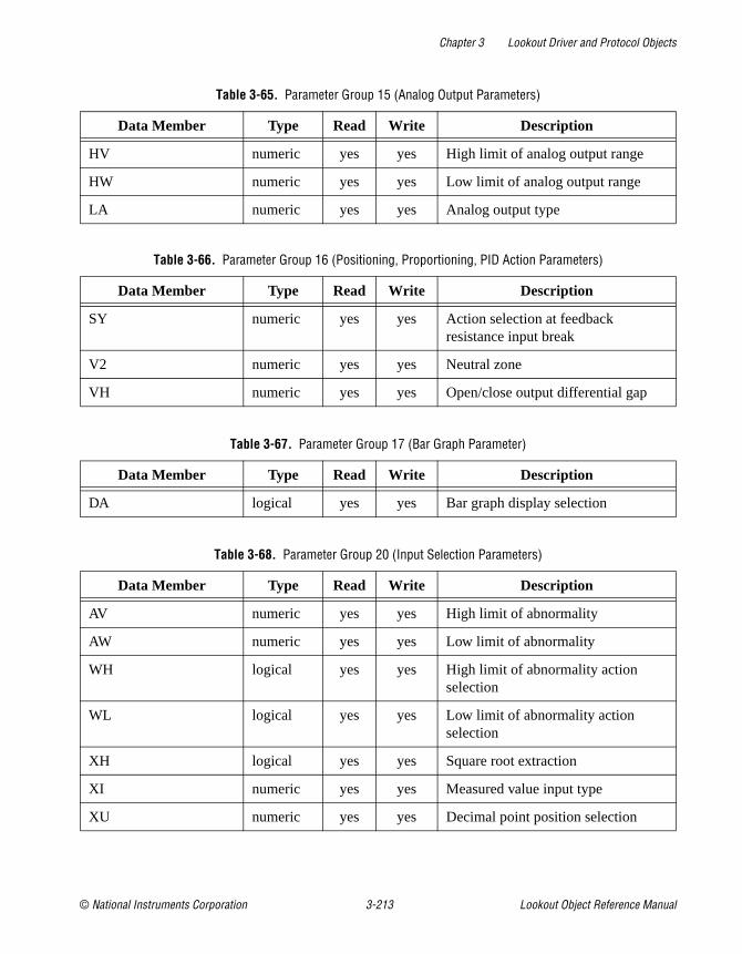
Chapter 3 Lookout Driver and Protocol Objects
© National Instruments Corporation 3-213 Lookout Object Reference Manual
Table 3-65. Parameter Group 15 (Analog Output Parameters)
Data Member Type Read Write Description
HV numeric yes yes High limit of analog output range
HW numeric yes yes Low limit of analog output range
LA numeric yes yes Analog output type
Table 3-66. Parameter Group 16 (Positioning, Proportioning, PID Action Parameters)
Data Member Type Read Write Description
SY numeric yes yes Action selection at feedback resistance input break
V2 numeric yes yes Neutral zone
VH numeric yes yes Open/close output differential gap
Table 3-67. Parameter Group 17 (Bar Graph Parameter)
Data Member Type Read Write Description
DA logical yes yes Bar graph display selection
Table 3-68. Parameter Group 20 (Input Selection Parameters)
Data Member Type Read Write Description
AV numeric yes yes High limit of abnormality
AW numeric yes yes Low limit of abnormality
WH logical yes yes High limit of abnormality action selection
WL logical yes yes Low limit of abnormality action selection
XH logical yes yes Square root extraction
XI numeric yes yes Measured value input type
XU numeric yes yes Decimal point position selection

Chapter 3 Lookout Driver and Protocol Objects
Lookout Object Reference Manual 3-214 www.natinst.com
XV numeric yes yes High limit of input programmable range
XW numeric yes yes Low limit of input programmable range
Table 3-69. Parameter Group 21 (Setting Parameters)
Data Member Type Read Write Description
SH numeric yes yes High limit of setting range
SL numeric yes yes Low limit of setting range
XL logical yes yes SV tracking selection
XR numeric yes yes Remote setting input type
Table 3-70. Parameter Group 22 (Output Action Parameters)
Data Member Type Read Write Description
SX numeric yes yes Start determination point
T0 numeric yes yes Control output cycle setting
T1 numeric yes yes Cooling-side output cycle setting
XE logical yes yes Direct/reverse action
XN numeric yes yes Action after power recovery setting
Table 3-71. Parameter Group 23 (Alarm 2 Parameters)
Data Member Type Read Write Description
XA numeric yes yes First alarm action
NA logical yes yes First alarm energized/de-energized
OA numeric yes yes First alarm action when measured value exceeds abnormality
WA numeric yes yes First alarm hold action
Table 3-68. Parameter Group 20 (Input Selection Parameters) (Continued)
Data Member Type Read Write Description

Chapter 3 Lookout Driver and Protocol Objects
© National Instruments Corporation 3-215 Lookout Object Reference Manual
XB numeric yes yes Second alarm action
NB logical yes yes Second alarm energized/de-energized
OB numeric yes yes Second alarm action when measured value exceeds abnormality
WB numeric yes yes Second alarm hold action
Table 3-72. Parameter Group 40 (Data Lock Parameters)
Data Member Type Read Write Description
DH logical yes yes Operation RUN/STOP display lock
LK numeric yes yes Data lock level setting
LL logical yes yes Memory area lock
Table 3-73. Lookout Data Members
Data Member Type Read Write Description
CommFail logical yes no Object-generated signal that is ON if Lookout cannot communicate with the device(s).
Poll logical no yes When this value transitions from FALSE to TRUE, Lookout polls the device.
PollRate numeric no yes Lookout expression that determines the device polling frequency.
Update logical yes no Object-generated signal that pulses low each time it polls the device.
Table 3-71. Parameter Group 23 (Alarm 2 Parameters) (Continued)
Data Member Type Read Write Description

Chapter 3 Lookout Driver and Protocol Objects
Lookout Object Reference Manual 3-216 www.natinst.com
RKC Status MessagesNo response within timeout period
Lookout received no response from a device within the Receive timeout period. The RKC object is able to use the COM port, but when it polls the device, it does not respond—as if it is not even there. If you have daisy-chained several devices, you have introduced an inherent delay. You may have to significantly increase Receive timeout (and Poll Rate) to ensure Lookout is allowing enough time to receive the expected response. This increase has nothing to do with the processing capabilities of Lookout. Rather it is based solely on Data rate and the number of devices on the chain. Also, verify your baud rate settings, cable connections, power, configuration settings, COM port settings, and polling addresses.
Invalid BCC in response
Lookout has received a frame with an invalid block check character (BCC). Check the cabling or look for two or more devices with the same address.
Invalid identifier in request
The request frame sent had an invalid identifier. This could possibly mean that you have requested an identifier that is not valid for your particular model in the RKC F Series. Check your model number carefully and read your RKC documentation to determine which identifiers are valid for which models.
Garbled or invalid frame
Lookout has received a frame without format characters in their proper positions. Check the Receive gap setting.
Numeric conversion failed
Lookout was unable to successfully convert ASCII data sent back from RKC into a number. Check the Receive gap setting.
No acknowledgment for write frame
There was no response to the write frame just sent. This could possibly mean that you have requested an identifier that is not valid for your particular model in the RKC F Series. Check your model number carefully and read RKC documentation to determine which identifiers are valid for which models.
RKC F Series models supported:
REX-F400, REX-F700, REX-F900

Chapter 3 Lookout Driver and Protocol Objects
© National Instruments Corporation 3-217 Lookout Object Reference Manual
S5_3964S5_3964 is a protocol driver class Lookout uses to communicate with Siemens Simatic S5 PLCs using the 3964 or 3964R protocols.
Figure 3-35. S5_3964 Definition Parameters Dialog Box
PLC Model specifies the model of Simatic S5 CPU the object communicates with.
Protocol specifies the protocol used to communicate with the PLC, 3964 or 3964R.
Serial port specifies which port the object uses for communication to the PLC.
Baud Rate specifies the speed at which the object communicates with the PLC.
Phone number specifies the number to be dialed if the serial port setting is configured for dial-up. This number only applies to the individual protocol object.
PollRate is a numeric expression that determines how often to poll the device. Normally, this is a simple time constant such as 0:01 (one second). See Numeric Data Members in Chapter 2, How Lookout Works, of the Getting Started with Lookout manual for information on entering time constants.
Poll is a logical expression. When this expression changes from FALSE to TRUE, Lookout polls the device. You can use a simple expression like the signal from a pushbutton, or a complex algorithm.

Chapter 3 Lookout Driver and Protocol Objects
Lookout Object Reference Manual 3-218 www.natinst.com
Communication alarm priority determines the priority level of object-generated alarms (0 – 10).
Receive timeout is the time the object waits for a response from a device before retrying a request.
Retry attempts specifies the consecutive number of times Lookout attempts to establish communications with a device if it is not getting a valid response. After it tries the number of Retry attempts specified, the object generates an alarm and releases the COM port. See Chapter 3, Serial Communications, in the Lookout Developer’s Manual for more information.
The Skip every… setting instructs the object that, in the event of a communications failure, to skip the next specified number of polls to the PLC before attempting to re-establish communications. Once communications have been re-established, the device is polled on its regular cycle.
S5_3964 Data MembersThis protocol driver object contains a great deal of data. All readable and writable members (inputs/outputs), polling instructions, read/write blocking, serial port usage, and so on, are bundled with the object. As soon as you create a S5_3964 object, you immediately have access to all the data members of that object.
Note Lookout protocol driver objects automatically generate an efficient read/write blocking scheme based on the inputs and outputs being used in your process file. You are not required to build your own I/O blocking table.
The suffixes for the PLC data members in Table 3-74 (KC, KF, and so on) follow the Siemens format for data suffixes. That is, KC for Counter format, KT for Timer format, KB for byte format, KF for fixed-point format, KG for floating-point format, and no suffix for those data members for which only one format is possible, such as bit fields, counters, and timers.
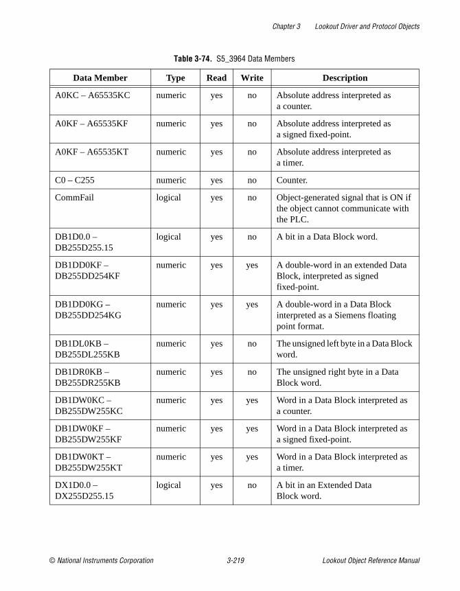
Chapter 3 Lookout Driver and Protocol Objects
© National Instruments Corporation 3-219 Lookout Object Reference Manual
Table 3-74. S5_3964 Data Members
Data Member Type Read Write Description
A0KC – A65535KC numeric yes no Absolute address interpreted as a counter.
A0KF – A65535KF numeric yes no Absolute address interpreted as a signed fixed-point.
A0KF – A65535KT numeric yes no Absolute address interpreted as a timer.
C0 – C255 numeric yes no Counter.
CommFail logical yes no Object-generated signal that is ON if the object cannot communicate with the PLC.
DB1D0.0 – DB255D255.15
logical yes no A bit in a Data Block word.
DB1DD0KF – DB255DD254KF
numeric yes yes A double-word in an extended Data Block, interpreted as signed fixed-point.
DB1DD0KG – DB255DD254KG
numeric yes yes A double-word in a Data Block interpreted as a Siemens floating point format.
DB1DL0KB – DB255DL255KB
numeric yes no The unsigned left byte in a Data Block word.
DB1DR0KB – DB255DR255KB
numeric yes no The unsigned right byte in a Data Block word.
DB1DW0KC – DB255DW255KC
numeric yes yes Word in a Data Block interpreted as a counter.
DB1DW0KF – DB255DW255KF
numeric yes yes Word in a Data Block interpreted as a signed fixed-point.
DB1DW0KT – DB255DW255KT
numeric yes yes Word in a Data Block interpreted as a timer.
DX1D0.0 – DX255D255.15
logical yes no A bit in an Extended Data Block word.

Chapter 3 Lookout Driver and Protocol Objects
Lookout Object Reference Manual 3-220 www.natinst.com
DX1DD0KG – DX255DD254KG
numeric yes yes A double-word in an Extended Data Block interpreted as a Siemens floating point format.
DX1DL0KB – DX255DL255KB
numeric yes no The unsigned left byte in an Extended Data Block word.
DX1DR0KB – DX255DR255KB
numeric yes no The unsigned right byte in an Extended Data Block word.
DX1DW0KC – DX255DW255KC
numeric yes yes Word in an Extended Data Block interpreted as a counter.
DX1DW0KF – DX255DW255KF
numeric yes yes Word in an Extended Data Block signed fixed-point.
DX1DW0KT – DX255DW255KT
numeric yes yes Word in an Extended Data Block interpreted as a timer.
F0.0 – F255.7 logical yes no A bit in Flag byte.
FD0KG – FD252KG numeric yes no A Flag double-word interpreted as a Siemens floating point format.
FW0KF – FW254KF numeric yes no A Flag word interpreted as a signed fixed-point.
FY0KB – FY255KB numeric yes no An unsigned Flag byte.
I0.0 – I127.7 logical yes no A bit in a byte of the Input (PII) data area.
IB0KB – IB127KB numeric yes no A unsigned byte of the Input (PII) data area.
ID0KG – ID124KG numeric yes no A double-word of the Input (PII) data area interpreted as a Siemens floating point format.
IW0KF – IW126KF numeric yes no Word in of the Input (PII) data area interpreted as a signed fixed-point.
Poll logical no yes When this expression transitions from FALSE to TRUE, Lookout polls the device.
Table 3-74. S5_3964 Data Members (Continued)
Data Member Type Read Write Description

Chapter 3 Lookout Driver and Protocol Objects
© National Instruments Corporation 3-221 Lookout Object Reference Manual
S5_3964 AlarmsObject Alarms
The following alarms originate in the object, and are only generated after the object has retried the request the number of times specified by the Retry attempts parameter.
No response from PLC
Lookout did not receive a response from the device within the Receive timeout period. The driver object is able to use the COM port, but when it polls the device, the device does not respond. You may have to increase Receive timeout to ensure Lookout is allowing enough time to receive the expected response. Also, verify your baud rate settings, cable connections, power, configuration settings, COM port settings, and polling addresses.
PollRate numeric no yes Lookout expression that determines the device polling frequency.
Q0.0 – Q127.7 logical yes no A bit in a byte of the Output (PIO) data area.
QB0KB – QB127KB numeric yes no An unsigned byte of the Output (PIO) data area.
QD0KG – QD124KG numeric yes no A double-word of the Output (PIO) data area interpreted as a Siemens floating point format.
QW0KF – QW126KF numeric yes no Word in of the Output (PIO) data area interpreted as a signed fixed-point.
RS0KC – RS511KC numeric yes no Word in the System data area interpreted as a signed fixed-point.
RS0KF – RS511KF numeric yes no Word in the System data area interpreted as a timer.
RS0KT – RS511KT numeric yes no Word in the System data area.
T0 – T255 numeric yes no Timer.
Update logical yes no Object-generated signal that pulses low each time it polls the device
Table 3-74. S5_3964 Data Members (Continued)
Data Member Type Read Write Description

Chapter 3 Lookout Driver and Protocol Objects
Lookout Object Reference Manual 3-222 www.natinst.com
Unexpected response from PLC
A response was received from the PLC, but not the response expected according to the protocol.
Bad frame
A response frame was received from the PLC, but the frame is not valid according to the protocol. This is usually caused by a truncated frame. You may need to increase the Receive Gap setting in the Options»Serial Ports… dialog.
Bad BCC
The BCC computed by the object for a received frame did not match the BCC in the frame.
PLC Alarms
The following alarms originate in the PLC, and are generated immediately by the object. There are no retry attempts.
Illegal DB/DX number
The Data Block (DB) or Extended Data Block (DX) number in a read/write request to a PLC was not valid for the PLC.
Synchronization error
The PLC and S5_3964 object are not synchronized within the protocol. This usually happens after the object is modified and a read/write request was interrupted. After generating the alarm, the S5_3964 object attempts to resynchronize the protocol in the PLC.

Chapter 3 Lookout Driver and Protocol Objects
© National Instruments Corporation 3-223 Lookout Object Reference Manual
S5_AS511S5_AS511 is a protocol driver class Lookout uses to communicate with Siemens Simatic S5 PLCs using the AS511 protocol.
Figure 3-36. S5_AS511 Definition Parameters Dialog Box
PLC Model specifies the model of Simatic S5 CPU the object communicates with.
Protocol specifies the protocol used to communicate with the PLC, 3964 or 3964R.
Serial port specifies which port the object uses for communication to the PLC.
Baud Rate specifies the speed at which the object communicates with the PLC.
Phone number specifies the number to be dialed if the serial port setting is configured for dial-up. This number only applies to the individual protocol object.
PollRate is a numeric expression that determines how often to poll the device. Normally, this is a simple time constant such as 0:01 (one second). See Numeric Data Members in Chapter 2, How Lookout Works, of the Getting Started with Lookout manual for information on entering time constants.

Chapter 3 Lookout Driver and Protocol Objects
Lookout Object Reference Manual 3-224 www.natinst.com
Poll is a logical expression. When this expression changes from FALSE to TRUE, Lookout polls the device. You can use a simple expression like the signal from a pushbutton, or a complex algorithm.
Communication alarm priority determines the priority level of object-generated alarms (0 – 10).
Receive timeout is the time the object waits for a response from a device before retrying a request.
Retry attempts specifies the consecutive number of times Lookout attempts to establish communications with a device if it is not getting a valid response. After it tries the number of Retry attempts specified, the object generates an alarm and releases the COM port. See Chapter 3, Serial Communications, in the Lookout Developer’s Manual for more information.
The Skip every setting instructs the object that, in the event of a communications failure, to skip the next specified number of polls to the PLC before attempting to re-establish communications. Once communications have been re-established, the device is polled on its regular cycle.
S5_AS511 Data MembersFor the PLC data members in Table 3-75, all of the suffixes that start with K (KC, KF, and so on) follow the Siemens format for data suffixes. That is, KC for Counter format, KT for Timer format, KB for byte format, KF for fixed-point format, KG for floating-point format, and no suffix for those data members for which only one format is possible, such as bit fields, counters, and timers. The other three suffixes, F, D, and T have been added to allow reading and writing IEEE 32-bit floating point (F), IEEE 64-bit floating point (D), and Lookout time (T). See Numeric Data Members in Chapter 2, How Lookout Works, of the Getting Started with Lookout manual for information on Lookout time format.
Table 3-75. S5_AS511 Data Members
Data Member Type Read Write Description
A0KB -A6535KB numeric yes yes Absolute address unsigned left byte in a data block word.
A0KC -A6535KC numeric yes yes Absolute address of a word in a data block interpreted as a counter.

Chapter 3 Lookout Driver and Protocol Objects
© National Instruments Corporation 3-225 Lookout Object Reference Manual
A0KF -A6535KF numeric yes yes Absolute address of a word in a data block interpreted as a signed fixed-point.
A0KG -A6535KG numeric yes yes Absolute address of a word in a data block interpreted as a Siemens floating-point.
A0KT -A6535KT numeric yes yes Absolute address of a word in a data block interpreted as a Siemens time format.
CommFail Logical yes no Object-generated signal that is ON if the object cannot communicate with the PLC.
DB1D0.0 – DB255D255.15
Logical yes no A bit in a Data Block word.
DB1DD0D – DB255DD254D
Numeric yes yes 64-bit in a Data Block interpreted as IEEE floating point format.
DB1DD0F – DB255DD254F
Numeric yes yes 32-bit in a Data Block interpreted as IEEE floating point format.
DB1DD0KF – DB255DD254KF
Numeric yes yes Single-word in a Data Block interpreted as signed fixed-point.
DB1DD0KG – DB255DD254KG
Numeric yes yes Double-word in a Data Block interpreted as Siemens floating point format.
DB1DL0KB – DB255DL255KB
Numeric yes no The unsigned left byte in a Data Block word.
DB1DR0KB – DB255DR255KB
Numeric yes no The unsigned right byte in a Data Block word.
DB1DW0KC – DB255DW255KC
Numeric yes yes Word in a Data Block interpreted as a counter.
DB1DW0KF – DB255DW255KF
Numeric yes yes Word in a Data Block interpreted as signed fixed-point.
DB1DW0KT – DB255DW255KT
Numeric yes yes Word in a Data Block interpreted as Siemens time format.
Table 3-75. S5_AS511 Data Members (Continued)
Data Member Type Read Write Description
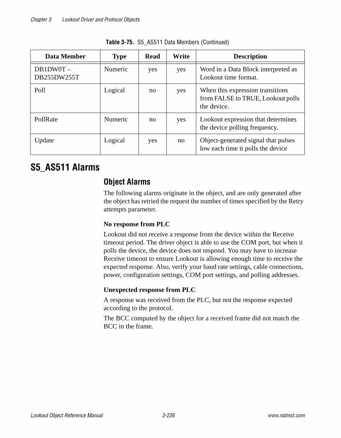
Chapter 3 Lookout Driver and Protocol Objects
Lookout Object Reference Manual 3-226 www.natinst.com
S5_AS511 AlarmsObject AlarmsThe following alarms originate in the object, and are only generated after the object has retried the request the number of times specified by the Retry attempts parameter.
No response from PLC
Lookout did not receive a response from the device within the Receive timeout period. The driver object is able to use the COM port, but when it polls the device, the device does not respond. You may have to increase Receive timeout to ensure Lookout is allowing enough time to receive the expected response. Also, verify your baud rate settings, cable connections, power, configuration settings, COM port settings, and polling addresses.
Unexpected response from PLC
A response was received from the PLC, but not the response expected according to the protocol.
The BCC computed by the object for a received frame did not match the BCC in the frame.
DB1DW0T – DB255DW255T
Numeric yes yes Word in a Data Block interpreted as Lookout time format.
Poll Logical no yes When this expression transitions from FALSE to TRUE, Lookout polls the device.
PollRate Numeric no yes Lookout expression that determines the device polling frequency.
Update Logical yes no Object-generated signal that pulses low each time it polls the device
Table 3-75. S5_AS511 Data Members (Continued)
Data Member Type Read Write Description

Chapter 3 Lookout Driver and Protocol Objects
© National Instruments Corporation 3-227 Lookout Object Reference Manual
PLC AlarmsThe following alarms originate in the PLC, and are generated immediately by the object. There are no retry attempts.
Illegal DB/DX number
The Data Block (DB) number in a read/write request to a PLC was not valid for the PLC.
Invalid datablock word number
The word number in a read/write request to a PLC was not valid for the specified Data Block (DB).

Chapter 3 Lookout Driver and Protocol Objects
Lookout Object Reference Manual 3-228 www.natinst.com
SiemensTI505SiemensTI505 is an Ethernet protocol driver object class Lookout uses to communicate with Siemens SIMATIC TI505 PLCs that are equipped with CP1431 NIMs. This driver is often referred to as Siemens H1.
Designed using the SINEC TF software library, this object class uses the SINEC H1 protocol and fully conforms to the application layer of the Siemens SINEC H1-TF protocol stack.
Your PC must be equipped with a Siemens CP 1413 Ethernet communications card and Siemens TF-NET 1413 software. See Configuring HI-TF in this section for instructions on setting up your H1 driver.
Figure 3-37. SiemensTI505 Definition Dialog Box
PLC Model specifies the PLC model number for the requested device. The list includes SIMATIC TI545, TI555 and TI565 PLCs.
Application association identifies an application name that you define using the SINEC Com1413t.exe program. This name identifies the physical device that your object represents. See Configuring HI-TF in this section for more information.

Chapter 3 Lookout Driver and Protocol Objects
© National Instruments Corporation 3-229 Lookout Object Reference Manual
PollRate is a numeric expression that determines how often to poll the device. SiemensTI505 then polls the device at the specified time interval. Normally, this is a simple time constant such as 0:01 (one second). See Numeric Data Members in Chapter 2, How Lookout Works, of the Getting Started with Lookout manual for more information on entering time constants.
Poll is a logical expression. When this expression changes from FALSE to TRUE, Lookout polls the device. You can use a simple expression like the signal from a pushbutton, or a complex algorithm.
Retry attempts specifies the consecutive number of times Lookout attempts to establish communications with a device if it is not getting a valid response. After it tries the number of Retry attempts specified, the object generates an alarm and releases the COM port. See Chapter 3, Serial Communications, in the Lookout Developer’s Manual for more information.
Receive timeout is the time delay Lookout uses in waiting for a response from a device before retrying the request.
Communication alarm priority determines the priority level of alarms generated by the SiemensTI505 object.
The Skip every ___ polls setting instructs Lookout not to poll a device it has lost communication with on every scheduled poll. Instead, Lookout skips the device in the polling cycle accordingly. Once communications have been reestablished, the device is polled on its regular cycle.
Configuring HI-TFInstall the Siemens TF-NET1413 MSDOS/Windows driver configuration software, including the COML 1413 TF configuration tool.
Configure the CP1413 Ethernet MAC address, memory map, and other settings by executing the following program from DOS (not Windows):
c:\sinec\bin\netinst.exe.
This creates a text file called C:\SINEC\DATA\DOS_conf.dat that stores the configuration parameters. You can later edit this file to change card settings in lieu of executing the install program.
If you are using a memory manager such as EMM386, add a memory exclude statement to your computer CONFIG.SYS file. For example, enter:
DEVICE=C:\WINDOWS\EMM386.EXE X=D000–DFFF

Chapter 3 Lookout Driver and Protocol Objects
Lookout Object Reference Manual 3-230 www.natinst.com
The CP 1413 Ethernet card uses 64 Kb of dual-ported RAM. Possible start addresses are D0000 and E0000.
Note Be sure to verify that no other drivers are mapped to the selected memory location.
From Windows, run C:\SINEC\COM\Com1413t.exe (the three-pawn icon) and configure the PLC name/address database that you download later to the CP 1413 card during system startup. Create a database file called STARTUP, and save it in the C:\SINEC\DATA directory.
This program creates two files, with your database represented by startup.ldb and startup.txt . These files contain the application association names that you need for each PLC.
Note There is a line of text in DOS_CONF.DAT that points to STARTUP.LDB. To use a different path or filename for your .ldb file, modify DOS_CONF.DAT to point to the file you create.
From Windows, activate C:\SINEC\H1\H1.exe (the single pawn icon) to create an H1 configuration file. Then, using the serial port on the NIM, download the configuration file to the H1 NIM in the PLC.
You must enter a unique Ethernet address and application association that matches one stored in the .LDB file. Also be sure that the Local TSAP and Remote TSAP values match exactly with the .LDB settings, except the Local TSAP and Remote TSAP values are swapped.
Create one H1 configuration file for each NIM in each PLC.
Note Application Association, Local TSAP, Remote TSAP, and just about everything else in the Siemens software is case sensitive.
Download the configuration to each NIM through the serial port on the NIM.
Edit your AUTOEXEC.BAT file and add the following command to the end of the file—but prior to any WIN command):
CALL C:\SINEC\BIN\STARTCP.BAT
Reboot your computer.

Chapter 3 Lookout Driver and Protocol Objects
© National Instruments Corporation 3-231 Lookout Object Reference Manual
Within Lookout, create a SIEMENSTI505 object for each PLC using the appropriate Application Association. You are now ready to access PLC variables in Lookout.
SiemensTI505 Data MembersProtocol driver objects contain a great deal of data. All readable and writable members (inputs/outputs), polling instructions, read/write blocking, serial port usage, and so on, are bundled with the object. Therefore, as soon as you create a SiemensTI505 object you immediately have access to all the object data members (see data member list in Table 3-76).
Note Lookout protocol driver objects automatically generate an efficient read/write blocking scheme based on the inputs and outputs being used in your process file. You are not required to build your own I/O blocking table.
Table 3-76. SiemensTI505 Data Members
Data Member Type Read Write Description
AACK1 – AACK32000 numeric yes yes (Analog Alarm) Alarm acknowledge flags
AADB1 – AADB32000 numeric yes yes (Analog Alarm) Deadband
ACF1 – ACF32000 numeric yes yes (Analog Alarm) Alarm C-flags
ACFH1 – ACFH32000 numeric yes yes (Analog Alarm) Alarm C-flags most significant word
ACFL1 – ACFL32000 numeric yes yes (Analog Alarm) Alarm C-flags least significant word
AERR1 – AERR32000 numeric yes yes (Analog Alarm) Alarm error
AHA1 – AHA32000 numeric yes yes (Analog Alarm) High alarm limit
AHHA1 – AHHA32000 numeric yes yes (Analog Alarm) High high alarm limit
ALA1 – ALA32000 numeric yes yes (Analog Alarm) Low alarm limit
ALLA1 – ALLA32000 numeric yes yes (Analog Alarm) Low low alarm limit
AODA1 – AODA32000 numeric yes yes (Analog Alarm) Orange deviation limit

Chapter 3 Lookout Driver and Protocol Objects
Lookout Object Reference Manual 3-232 www.natinst.com
APV1 – APV32000 numeric yes yes (Analog Alarm) Process variable
APVH1 – APVH32000 numeric yes yes (Analog Alarm) Process variable high limit
APVL1 – APVL32000 numeric yes yes (Analog Alarm) Process variable low limit
ARCA1 – ARCA32000 numeric yes yes (Analog Alarm) Rate of change limit
ASP1 – ASP32000 numeric yes yes (Analog Alarm) Setpoint
ASPH1 – ASPH32000 numeric yes yes (Analog Alarm) Setpoint high limit
ASPL1 – ASPL32000 numeric yes yes (Analog Alarm) Setpoint low limit
ATS1 – ATS32000 numeric yes yes (Analog Alarm) Sample rate
AVF1 – AVF32000 numeric yes yes (Analog Alarm) Alarm flags
AYDA1 – AYDA32000 numeric yes yes (Analog Alarm) Yellow deviation limit
C1 – C32000 logical yes yes Control Registers
CommFail logical yes no Driver-generated signal that is ON if Lookout cannot communicate with the device for whatever reason
DCC1 – DCC32000 numeric yes no Drum current count
DSC1 – DSC32000 numeric yes yes Drum step current
DSP1 – DSP32000 numeric yes yes Drum step preset
K1 – K32000 numeric yes yes K-memory unsigned 16-bit integer value ranging from 0 to 65535
K1. – K32000. numeric yes yes K-memory 32-bit IEEE floating point value
K1D – K32000D numeric yes yes K-memory 32-bit unsigned integer value
K1S – K32000S numeric yes yes K-memory signed 16-bit integer value ranging from –32768 to 32767
LACK1 – LACK32000 numeric yes yes (Loop) Alarm Acknowledge Flags
Table 3-76. SiemensTI505 Data Members (Continued)
Data Member Type Read Write Description

Chapter 3 Lookout Driver and Protocol Objects
© National Instruments Corporation 3-233 Lookout Object Reference Manual
LADB1 – LADB32000 numeric yes yes (Loop) Deadband
LCF1 – LCF32000 numeric yes yes (Loop) C-flags
LCFH1 – LCFH32000 numeric yes yes (Loop) C-flags most significant word
LCFL1 – LCFL32000 numeric yes yes (Loop) C-flags least significant word
LERR1 – LERR32000 numeric yes no (Loop) Error
LHA1 – LHA32000 numeric yes yes (Loop) High alarm limit
LHHA1 – LHHA32000 numeric yes yes (Loop) High high alarm limit
LKC1 – LKC32000 numeric yes yes (Loop) Gain
LKD1 – LKD32000 numeric yes yes (Loop) Derivative gain
LLA1 – LLA32000 numeric yes yes (Loop) Low alarm limit
LLLA1 – LLLA32000 numeric yes yes (Loop) Low low alarm limit
LM1 – LM32000 numeric yes yes (Loop) Mode
LMN1 – LMN32000 numeric yes yes (Loop) Output
LMX1 – LMX32000 numeric yes yes (Loop) Bias
LODA1 – LODA32000 numeric yes yes (Loop) Orange deviation limit
LPV1 – LPV32000 numeric yes yes (Loop) Process variable
LPVH1 – LPVH32000 numeric yes yes (Loop) Process variable high limit
LPVL1 – LPVL32000 numeric yes yes (Loop) Process variable low limit
LRCA1 – LRCA32000 numeric yes yes (Loop) Rate of change limit
LRSF1 – LRSF32000 numeric yes yes (Loop) Ramp/Soak status flags
LS1 – LS32000 numeric yes no (Loop) Status
LSP1 – LSP32000 numeric yes yes (Loop) Setpoint
LSPH1 – LSPH32000 numeric yes yes (Loop) Setpoint high limit
LSPL1 – LSPL32000 numeric yes yes (Loop) Setpoint low limit
LTD1 – LTD32000 numeric yes yes (Loop) Rate
LTI1 – LTI32000 numeric yes yes (Loop) Reset
Table 3-76. SiemensTI505 Data Members (Continued)
Data Member Type Read Write Description

Chapter 3 Lookout Driver and Protocol Objects
Lookout Object Reference Manual 3-234 www.natinst.com
LTS1 – LTS32000 numeric yes yes (Loop) Sample rate
LVF1 – LVF32000 numeric yes yes (Loop) V-flags
LYDA1 – LYDA32000 numeric yes yes (Loop) Yellow deviation limit
Poll logical no yes When this value transitions from FALSE to TRUE, the Lookout object polls the device
PollRate numeric no yes Specifies the frequency at which the Lookout object polls the device
TCC1 – TCC32000 numeric yes yes (Analog Alarm) Timer/counter current
TCP1 – TCP32000 numeric yes yes (Analog Alarm) Timer/counter preset
Update logical yes no Driver-generated signal that pulses each time the driver polls the device
V1 – V32000 numeric yes yes V-memory unsigned 16-bit integer value ranging from 0 to 65535
V1. – V32000. numeric yes yes V-memory 32-bit IEEE floating point value
V1D – V32000D numeric yes yes V-memory 32-bit unsigned integer value
V1S – V32000S numeric yes yes V-memory signed 16-bit integer value ranging from –32768 to 32767
WX1 – WX32000 numeric yes no Word Image Inputs—16-bit values that typically range from 6400 – 32000 for 4 – 20 mA signals, and 0 – 32000 for 0 – 5V signals.
WY1 – WY32000 numeric yes yes Word Image Outputs—16-bit values that typically range from 6400 – 32000 for 4 – 20 mA signals, and 0 – 32000 for 0 – 5V signals.
Table 3-76. SiemensTI505 Data Members (Continued)
Data Member Type Read Write Description

Chapter 3 Lookout Driver and Protocol Objects
© National Instruments Corporation 3-235 Lookout Object Reference Manual
SiemensTI505 Status MessagesThe following alarms are SINEC error codes returned by the Siemens software. For more detailed information, consult the Siemens SINEC TF documentation.
• cannot initialize Sinec TF service
• hardware error
• invalid address
• invalid app. assoc. name: xxxx
• more than one object using same app. assoc.
• no more space in PDU
• no response
• no response (reconnecting)
• not available at times
• object access not allowed
• object attribute inconsistent
• object does not exist
• object not defined
• object now invalid
• type not supported
• type/alt acc. not consistent
X1 – X32000 logical yes no Discrete Inputs—unassigned Xs may be used as control registers
Y1 – Y32000 logical yes yes Discrete Outputs—same memory space as Discrete Inputs, so X37 references the same point as Y37. Unassigned Ys may be used as control registers
Table 3-76. SiemensTI505 Data Members (Continued)
Data Member Type Read Write Description

Chapter 3 Lookout Driver and Protocol Objects
Lookout Object Reference Manual 3-236 www.natinst.com
SixnetSixnet is a protocol driver object class Lookout uses to communicate with Sixnet IOMUX RTUs (remote terminal units), Versamux RTUs, and DIN rail-mounted Sixtrak I/O modules.
The Lookout Sixnet object class establishes an interface to the Sixnet Control Room software using direct DLL calls (not DDE). Using this seamless connection between programs, Lookout can communicate with Sixnet devices through your serial port (RS-232 or RS-422/485), through Ethernet, or RTUnet.
Note This protocol driver object class requires Version 1.0 or later of Sixnet Control Room I/O Map software, and Version 3.5 build 15 (or later) of Lookout.
Create one Lookout Sixnet object for each station you define in the Control Room software. In order to make Sixtags names correspond as closely as possible to Lookout alias names, you should name the Lookout objects using the eight-letter prefixes of the Sixnet stations.
Figure 3-38. Sixnet Configuration Parameters Dialog Box
Station name is a pull-down list box of all stations defined in the Control Room software. Select the station that you want the object to represent.
PollRate is a numeric expression that specifies how often Lookout polls the Control Room software. Normally, this is a simple time constant such as 0:01 (one second), but you may choose to make this a complex expression, making the PollRate change dynamically based on criteria that you specify. See Numeric Data Members in Chapter 2, How Lookout Works, of the Getting Started with Lookout manual for information on entering time constants and variables.

Chapter 3 Lookout Driver and Protocol Objects
© National Instruments Corporation 3-237 Lookout Object Reference Manual
Poll is a logical expression. When this expression changes from FALSE to TRUE, Lookout polls the device. You can use a simple expression like the signal from a pushbutton, or a complex algorithm.
Communication alarm priority determines the priority level of alarms generated by the Lookout Sixnet object. Such alarms are typically related to DLL handshaking with the Control Room software.
Sixnet Data MembersA Sixnet object represents all values within a given station; therefore, it can contain a great deal of data. The object can read and write all possible data point types, including predefined and user-defined I/O types. When you create a Sixnet object, you have immediate access to all data within the assigned station (see Sixnet Data Members in Table 3-77).
Each register in the Sixnet I/O Map corresponds to a data member within the Lookout Sixnet object. The register I/O type number and address are encoded into the name of the data member. Predefined I/O type numbers correspond with Lookout data member prefixes as follows.
For user-defined I/O types, the Sixnet I/O type number is specified by the name of the Lookout data member which takes the following form:
<DataType><ioTypeNumber>:<Address>
where <DataType> is Bit, Byte, Short, Word, Long, Float, or Double; <ioTypeNumber> is a number between 0 and 126 inclusive; and <Address> is a number whose legal range depends on the data type. Thus the Lookout point Sixnet1.Word33:99 corresponds to the hundredth register with
I/O Type Number Data Member Prefix
0 AI (Analog In)
1 AO (Analog Out)
10 DI (Discrete In)
11 DO (Discrete Out)
20 LongIn
21 LongOut
22 FloatIn
23 FloatOut

Chapter 3 Lookout Driver and Protocol Objects
Lookout Object Reference Manual 3-238 www.natinst.com
I/O type number 33 for the station with name Sixnet1.Station . The register is read as a word (that is, an unsigned 16-bit number).
You can use any data type with any I/O type number in Lookout. This means that you can read a long (32-bit signed number) from two consecutive analog registers. This makes it very easy to get the value of a 32-bit counter that is stored in consecutive 16-bit registers in a PLC. For example, the data member Long0:7 would correspond to analog inputs AI7 and AI8 and it would be interpreted as a signed, 32-bit register. This capability also means that you have the choice of reading an analog value as either a signed value (using AI0 or Short0:0 ) or as an unsigned value (using Word0:0 ).
Note Writing a bit to an analog register sets that analog value to 0 or 1. It does not set just one of the bits to 0 or 1.
Table 3-77. Sixnet Data Members
Data Member Type Read Write Description
AI0 – AI32499 numeric yes yes Analog input encoded as a 16-bit signed integer ranging from –32768 to +32767
AO0 – AO32499 numeric yes yes Analog output encoded as a 16-bit signed integer ranging from –32768 to +32767
Bit0:0 – Bit126:64999 logical yes yes User-defined discrete I/O (TRUE or FALSE)
Byte0:0 – Byte126:64999
numeric yes yes User-defined register encoded as an 8-bit unsigned integer ranging from zero to 255
CommFail logical yes no Driver-generated signal that is ON if Lookout cannot communicate with the device for whatever reason
DI0 – DI64999 logical yes yes Discrete input (TRUE or FALSE)
DO0 – DO64999 logical yes yes Discrete output (TRUE or FALSE)
Double0:0 – Double126:8124
numeric yes yes User-defined I/O referring to 4 consecutive registers encoded as a single 64-bit floating point value

Chapter 3 Lookout Driver and Protocol Objects
© National Instruments Corporation 3-239 Lookout Object Reference Manual
Float0:0 – Float126:16299
numeric yes yes User-defined register pair encoded as a 32-bit IEEE floating point value
FloatIn0 – FloatIn16299 numeric yes yes 32-bit IEEE floating point value —reads two adjacent registers as a single 32-bit floating point value
FloatOut0 – FloatOut16299
numeric yes yes 32-bit IEEE floating point value —writes two adjacent registers as a single 32-bit floating point value
Long0:0 – Long126:16299
numeric yes yes User-defined register pair encoded as a signed 32-bit long integer. Lookout reads two adjacent registers as a single 32-bit number ranging from –2147483648 to +2147483647.
LongIn0 – LongIn16299 numeric yes yes Long input encoded as a signed 32-bit long integer. Lookout reads two adjacent registers as a single 32-bit number ranging from –2147483648 to +2147483647.
LongOut0 – LongOut16299
numeric yes yes Long output encoded as a signed 32-bit long integer. Lookout writes two adjacent registers as a single 32-bit number ranging from –2147483648 to +2147483647.
Poll logical no yes When this value transitions from FALSE to TRUE, Lookout polls the device.
PollRate numeric no yes Lookout expression that determines the device polling frequency.
Short0:0 – Short126:32499
numeric yes yes User-defined register encoded as 16-bit signed integer ranging from –32767 to +32768
Station text yes no Station name (such as, Local Computer)
Table 3-77. Sixnet Data Members (Continued)
Data Member Type Read Write Description
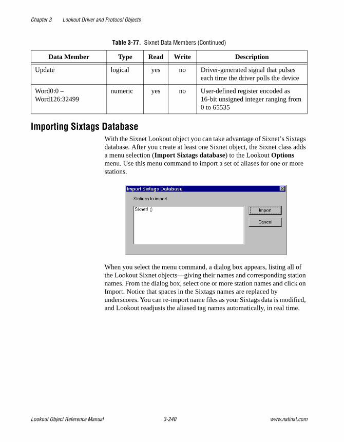
Chapter 3 Lookout Driver and Protocol Objects
Lookout Object Reference Manual 3-240 www.natinst.com
Importing Sixtags DatabaseWith the Sixnet Lookout object you can take advantage of Sixnet’s Sixtags database. After you create at least one Sixnet object, the Sixnet class adds a menu selection (Import Sixtags database) to the Lookout Options menu. Use this menu command to import a set of aliases for one or more stations.
When you select the menu command, a dialog box appears, listing all of the Lookout Sixnet objects—giving their names and corresponding station names. From the dialog box, select one or more station names and click on Import. Notice that spaces in the Sixtags names are replaced by underscores. You can re-import name files as your Sixtags data is modified, and Lookout readjusts the aliased tag names automatically, in real time.
Update logical yes no Driver-generated signal that pulses each time the driver polls the device
Word0:0 – Word126:32499
numeric yes no User-defined register encoded as 16-bit unsigned integer ranging from 0 to 65535
Table 3-77. Sixnet Data Members (Continued)
Data Member Type Read Write Description

Chapter 3 Lookout Driver and Protocol Objects
© National Instruments Corporation 3-241 Lookout Object Reference Manual
Sixnet Status MessagesUnable to load Sixnet IOMAP library: iodbase.dll
The Sixnet software is not installed—Lookout cannot find the iodbase.dll library. Make sure that you have installed the Control Room software properly. This should put the iodbase.dll library into the \WINDOWS\SYSTEM directory.
No Sixnet configuration currently loaded
The Sixnet I/O Map software is not running yet. Use the Sixnet I/O Map program to open and run a project file. According to the Sixnet I/O Map help file, your DLL must be loaded and scanning before Lookout can control I/O. The easiest way to load the DLL and start scanning is to run the Control Room Power Switch. You could also select the Run command from the Control menu in the Sixnet I/O Map.
Station <name> is not on line
Sixnet reports that the named station is not on line. Lookout might still be able to read from and write to registers for that station, but the updates will not be propagated to the remote device.
Read error (<station name>, type <type number>, address <address>)Write error (<station name>, type <type number>, address <address>)
One of the following reasons will be given:
• Address out of range
• Bad station, address, or type number
• Bad type number

Chapter 3 Lookout Driver and Protocol Objects
Lookout Object Reference Manual 3-242 www.natinst.com
SquareDLookout uses the SquareD object class to communicate with the SquareD family of SCP PLCs. These include the SCP-1xx, 3xx, 4xx, 5xx, 6xx, and 7xx series. Lookout can interface to Square D PLCs through either a serial interface or a SY/MAX interface. The SY/MAX interface supports both SY/MAX and net-to-net communication modes.
Figure 3-39. SquareD Definition Parameters Dialog Box Configured for Serial Communications
Route refers to a unique path through any network devices that leads to the PLC port. Remember, when using the SY/MAX card, the first route must be a zero followed by the address of the card. This is because the SY/MAX card edge is considered to be port zero. The RS422 port on the SY/MAX card is considered to be port one.
Model specifies the particular type of PLC you are representing with this object. The Model you select determines what native data members comprise the object.
PollRate is a numeric expression that determines how often to poll the device. Lookout polls the device at the specified time interval. Normally, this is a simple time constant such as 0:01 (one second). See Numeric Data Members in Chapter 2, How Lookout Works, of the Getting Started with Lookout manual for information on entering time constants.

Chapter 3 Lookout Driver and Protocol Objects
© National Instruments Corporation 3-243 Lookout Object Reference Manual
Poll is a logical expression. When this expression changes from FALSE to TRUE, Lookout polls the device. You can use a simple expression like the signal from a pushbutton, or a complex algorithm.
Communication alarm priority determines the priority level of the alarms generated by the SquareD object.
Retry attempts specifies the consecutive number of times Lookout attempts to establish communications with a device if it is not getting a valid response. After it tries the number of Retry attempts specified, the object generates an alarm and begins to Skip every n poll requests after comm failure. Once Lookout reestablishes communications, it polls the device on its regular cycle, as defined by PollRate.
Receive timeout is the time Lookout waits for a response from a device before retrying the poll request.
Serial Port Interface ParametersThe Serial Interface selection enables serial port communication from your computer to the programming port on your PLC. The previous diagram shows a Square D PLC configured for serial communications.
Serial port specifies which RS-232C port on your computer the object uses for communication to the physical device.
Data rate, Parity, Data Bits, and Stop bits reference the settings of the hardware device. Choose the settings as configured on you PLC.
Phone number specifies the number to be dialed if the serial port setting is configured for dial-up. This number only applies to the individual object. See Options»Serial Ports for more information.

Chapter 3 Lookout Driver and Protocol Objects
Lookout Object Reference Manual 3-244 www.natinst.com
SY/LINK Interface ParametersThe SY/LINK Interface selection enables direct connection of your computer to a Square D network using a SY/MAX card. The following diagram shows a SquareD object configured for SY/MAX communications.
Figure 3-40. SquareD Definition Dialog Box Configured for SY/LINK Communications
Network address identifies the address of your computer interface card in the SY/MAX network. Valid addresses range from 0 to 99. The card node address must be unique—that is, it must not be the same as the address of any other device on the network.
Interrupt identifies the interrupt (IRQ) setting of your SY/MAX interface card in your PC. Assigning an interrupt to the interface card improves overall computer performance. Any time the card receives an response, it generates an interrupt recognized by Lookout.
Card memory address specifies the base address location of the card memory. This is selected for you automatically. At present, only one SY/MAX card in a computer is supported. Lookout looks for the card and fills this box with its address. If the card is not found, this is indicated here as well.

Chapter 3 Lookout Driver and Protocol Objects
© National Instruments Corporation 3-245 Lookout Object Reference Manual
Network settings include net size and baud rate. Net size identifies the number of devices on the network. The SY/MAX card and all of the PLCs or NIMs must have the same settings for successful communications to occur. A net size of 31 should promote a faster response time. Baud rate selects the baud rate at which the SY/LINK card tries to communicate on the SY/NET network.
The RS-422 settings include baud rate, parity, and word size. These parameters reference the settings of the hardware device. Choose the settings as configured on you PLC.
RS-422 mode chooses either SY/MAX or Net-to-net . Choosing SY/MAX allows normal network operations. Choosing Net-to-net allows extended distributed networks, large capacity networks (more than 200 devices), or network redundancy (more than one path between two devices). The default is SY/MAX.
SY/ENET Interface ParametersThe SY/ENET Interface selection enables direct connection of your computer to an Ethernet network using an Ethernet card. SY/ENET is only available on computers running Windows NT. You cannot use SquareD ENET under Windows 95.
To use SquareD with the ENET protocol, you must install the Lookout Ethernet driver as a protocol in the Windows Network Control Panel. Lookout installs the files LKETHER.SYS and OEMSETUP.INF when you install Lookout. To install the Lookout Ethernet Driver, select Settings»Control Panel»Network and click on the Protocols tab. Click Add, and then click Have Disk, changing the default path from A:\ to your main Lookout directory. Follow the onscreen instructions to complete installation of the driver.

Chapter 3 Lookout Driver and Protocol Objects
Lookout Object Reference Manual 3-246 www.natinst.com
The following diagram shows a SquareD object configured for SY/ENET communications.
Figure 3-41. SquareD Definition Dialog Box Configured for SY/ENET Communications
Route refers to a unique path through any network devices that leads to the PLC port.
Using SY/ENET with More Than One Ethernet Board in Your SystemIf you have more than one Ethernet board installed in your computer, you must configure your system properly to use the SquareD driver object.
Open the Network Dialog Box from Settings»Control Panel»Network and select the Bindings name. Under the Lookout Ethernet Driver Heading, highlight all ethernet boards except the one connected to your SquareD network, and click on the Disable button. For instance, in the following illustration, the Intel Ether Express 16 LAN adapter is connected to the SquareD network.

Chapter 3 Lookout Driver and Protocol Objects
© National Instruments Corporation 3-247 Lookout Object Reference Manual
Next select the Services tab.

Chapter 3 Lookout Driver and Protocol Objects
Lookout Object Reference Manual 3-248 www.natinst.com
Highlight NetBios Interface and click on Properties. The NetBIOS Configuration dialog box appears.
Make sure that the Square D Ethernet card is LANA Number 000 and the Network Route is Nbf .
SquareD Data MembersEach SquareD object contains a great deal of data. All readable and writable members (inputs/outputs) are bundled with the object. As soon as you create an object you immediately have access to all the object data members.
Note The SquareD object class automatically generates an efficient read/write blocking scheme based on the inputs and outputs you are using in your process file. You are not required to build your own I/O blocking table. However, you can ensure peak performance by organizing your PLCs data into contiguous groups.
Table 3-78. SquareD Data Members
Data Member Type Read Write Description
1 – 8176 numeric yes yes 16-bit unsigned integer ranging from 0 to 65535
1. – 8176. logical yes yes Logical I/O that reads and writes the entire register. When you write to the register, all bits in the word go TRUE or FALSE.

Chapter 3 Lookout Driver and Protocol Objects
© National Instruments Corporation 3-249 Lookout Object Reference Manual
SquareD Error MessagesThe SquareD object class reports the status of commands it issues to the PLC. When Lookout receives an error response from a PLC, it reports the failure as an alarm containing the status code and its meaning. The following are a few examples of such alarms:
SY/MAX initialization error:(0)Cannot initialize SY/LINK board SY/MAX polling error:(3)Illegal address attempted Response error:(3) Received NAK in response
1.0 – 8176.15 logical yes yes Individual bits in a register read as logical ON/OFF values. The least significant bit is 0; the most significant, 15.
CommFail logical yes no Object-generated signal that is on if, for whatever reason, Lookout cannot communicate with the PLC.
F1 – F8175 (odd only)
numeric yes yes 32-bit IEEE floating point register—reads two adjacent holding registers as a single 32-bit floating point value
Poll logical no yes When this value transitions from FALSE to TRUE, the Lookout object polls the PLC device
PollRate numeric no yes Specifies the frequency at which the Lookout object polls the PLC device
S1 – S8176 numeric yes yes 16-bit signed word ranging from –32,768 to +32,768
Update logical yes no Object-generated signal that pulses each time the object polls the device
Table 3-78. SquareD Data Members (Continued)
Data Member Type Read Write Description

Chapter 3 Lookout Driver and Protocol Objects
Lookout Object Reference Manual 3-250 www.natinst.com
TescoTesco is a protocol driver object class Lookout uses to communicate with Liquitronic LIQ programmable controllers using the LIQ4 (Data Express) and LIQ5 (Data Express Plus) messaging protocols. Create one Tesco object for each controller.
Figure 3-42. Tesco Configuration Parameters Dialog Box
Route refers to the PLC address setting as specified in its Configuration Table. When using LIQ4 , it is a simple node address (1 to 255). When using LIQ5 , Route contains both the network address and the node address in the format network.node , as shown in the diagram.
Serial port specifies which port the object uses for communication to the external device. This does not specify the communication topology (such as, radio, dial-up, hard wired). Communication type is determined by the Options»Serial Ports… command.
Data rate, Parity, and Stop bits reference the settings on the hardware device.
The Defaults button replaces the current settings with default values.
Alarm priority determines the priority level of Tesco communication alarms.

Chapter 3 Lookout Driver and Protocol Objects
© National Instruments Corporation 3-251 Lookout Object Reference Manual
Phone number specifies the number to be dialed if the serial port setting is configured for dial-up. This number only applies to the individual driver object.
PollRate is a numeric expression that determines how often to poll the device. The Tesco object then polls the device at the specified time interval. Normally, this is a simple time constant such as 0:01 (one second). See Numeric Data Members in Chapter 2, How Lookout Works, of the Getting Started with Lookout manual for more information on entering time constants.
Poll is a logical expression. When this expression changes from FALSE to TRUE, Lookout polls the device. You can use a simple expression like the signal from a pushbutton, or a complex algorithm.
Retry attempts specifies the consecutive number of times Lookout attempts to establish communications with a device it does not get a valid response from. After Retry attempts times, the object generates a communication alarm and Lookout moves on to the next device in the polling queue (if any).
Receive timeout is the time delay Lookout uses in waiting for a response from a device before retrying the request.
The Skip every N poll requests after comm failure setting instructs Lookout not to poll a device it has lost communication with on every scheduled poll. Instead, Lookout skips the device in the polling cycle accordingly. Once communications are reestablished, the device is polled on its regular cycle.
Selecting the Accept quiescent messages checkbox enables Lookout to accept unsolicited, unpolled messages from the PLC. This parameter applies to LIQ IV only.
Node Address denotes the address of the computer you are running Lookout on in the TESCO device route. The default value is 253 . This parameter applies to LIQ IV only.

Chapter 3 Lookout Driver and Protocol Objects
Lookout Object Reference Manual 3-252 www.natinst.com
Tesco Data MembersLike other protocol driver objects, Tesco objects can contain a great deal of data. All readable and writable members (inputs/outputs), polling instructions, and so on, are bundled with the object. As soon as you create a Tesco object you immediately have access to all the object data members (see the data member list in Table 3-79).
Table 3-79. Tesco Data Members
Data Members Type Read Write Description
AO0 – AO1023 numeric yes yes Analog Output register capable of holding a 32-bit IEEE floating point value for use in internal Tescode programming, or a physical AO signal value as a 12-bit whole number ranging from 0 to 4095.
CommFail logical yes no Driver-generated signal that is ON if Lookout cannot communicate with the device for whatever reason.
IR0 – 1R1023 numeric yes yes Index register containing a 32-bit unsigned integer ranging from 0 to 4,294,967,295.
L0 – L1023 numeric yes yes Level (Analog Input) register capable of holding a 32-bit IEEE floating point value for use in internal Tescode programming, or a physical AI signal as a 12-bit whole number ranging from 0 to 4095.
P0 – P1023 logical yes yes Pump (Discrete Output) register associated with a physical output channel.
Poll logical no yes When this value transitions from FALSE to TRUE, Lookout polls the device.
PollRate numeric no yes Specifies the frequency at which the device is to be polled.

Chapter 3 Lookout Driver and Protocol Objects
© National Instruments Corporation 3-253 Lookout Object Reference Manual
S0 – S1023 logical yes yes Status (Digital Input) register that can represent either a physical input channel or an internal Tescode programming flag.
SP0 – SP1023 numeric yes yes Setpoint register that holds a 32-bit IEEE floating point value with a range of +/–3.37 × 1038
T0 – T1023 numeric yes yes Timer/Counter register containing Pulse counters, Hours timers, HMS timers, Event counters, and Seconds timers as documented in the TESCO LIQ 5 Programmable Control Operations Manual
Update logical yes no Driver-generated signal that pulses each time the driver polls the device
Table 3-79. Tesco Data Members (Continued)
Data Members Type Read Write Description

Chapter 3 Lookout Driver and Protocol Objects
Lookout Object Reference Manual 3-254 www.natinst.com
TiwayTiway is a protocol driver object Lookout uses to communicate with series 5xx PLCs manufactured by Siemens, formerly made by Texas Instruments.
Protocol driver objects contain a great deal of data. All readable and writable members (inputs/outputs), polling instructions, read/write blocking, serial port usage, and so on are bundled with the object. As soon as you create a Tiway object you immediately have access to all the object data members (see data member list in this section).
Note Lookout protocol driver objects automatically generate an efficient read/write blocking scheme based on the inputs and outputs being used in your process file. You are not required to build your own I/O blocking table.
Figure 3-43. Tiway Configuration Parameters Dialog Box
PLC Model specifies the PLC model number for the requested device.
PollRate is a numeric expression that determines how often to poll the device. Tiway then polls the device at the specified time interval. Normally, this is a simple time constant such as 0:01 (one second). See Numeric Data Members in Chapter 2, How Lookout Works, of the Getting Started with Lookout manual for more information on entering time constants.

Chapter 3 Lookout Driver and Protocol Objects
© National Instruments Corporation 3-255 Lookout Object Reference Manual
Poll is a logical expression. When this expression changes from FALSE to TRUE, Lookout polls the device. You can use a simple expression like the signal from a pushbutton, or a complex algorithm.
Receive timeout is the time delay Lookout uses in waiting for a response from a device before retrying the request.
Retry attempts specifies the consecutive number of times Lookout attempts to establish communications with a device it does not get a valid response from. After Retry attempts times, Tiway generates a communication alarm and Lookout moves on to the next device in the polling queue (if any).
Alarm priority determines the priority level of Tiway generated alarms.
Phone number specifies the number to be dialed if the serial port setting is configured for dial-up. This number only applies to the individual protocol object.
The Skip every ___ polls setting instructs Lookout not to poll a device it has lost communication with on every scheduled poll. Instead, Lookout skips the device in the polling cycle accordingly. Once communications have been reestablished, the device is polled on its regular cycle.
Communication TechniquesLookout communicates with Siemens PLCs in several ways: direct serial connection to the Local port , serial connection to an external Unilink Host Adapter, through an internal Unilink PC Adapter card, or through an internal CTI TCP/IP card.
Local PortThe Local port settings determine the serial port, data rate, and phone number (if any) to be used in a direct connect setup. Because the Local port protocol does not include address information, this option is limited to only one (1) PLC per serial port.

Chapter 3 Lookout Driver and Protocol Objects
Lookout Object Reference Manual 3-256 www.natinst.com
Unilink Host AdapterIf Unilink Host Adapter is selected, you must specify the Serial port to be used and the NIM (Network Interface Module) address as set at the PLC. You also should configure several settings on the Unilink Host Adapter by selecting the Configure UHA… button.
The settings in this dialog box are globally applied to all PLCs on the specified TIWAY network (each network requires a separate serial port). Therefore, it is only necessary to configure each Unilink Host Adapter one time—you need not repeat this step every time you create a new Tiway object.
Data rate specifies the communication speed between the computer and the Unilink Host Adapter. It also determines the required dip switch settings on the UHA for the selected baud rate.
The Host Adapter Operating Mode determines if the Unilink Host Adapter is the network manager (Master Host Interface Unit) or just another network secondary (Host Interface Unit). There must be exactly one MHIU per TIWAY network.
Enabling Automatic redundant media instructs the Unilink Host Adapter to attempt communications over a redundant TIWAY network to any secondary it loses communications with.

Chapter 3 Lookout Driver and Protocol Objects
© National Instruments Corporation 3-257 Lookout Object Reference Manual
The TIWAY I Network Settings configure the communication parameters for the TIWAY network. This network runs between the Unilink Host Adapter and its secondaries. The Lookout default network settings correspond to the default NIM settings as shipped from Siemens. See your TIWAY documentation to modify any of these parameters.
Unilink PC AdapterBecause the Unilink PC Adapter is an internal card, it eliminates the 19200 baud serial bottleneck and replaces it with the 8 MHz PC ISA bus speed. Therefore, the performance gains over the Unilink Host Adapter and Local port settings can be substantial.
If Unilink PC Adapter is selected, you must specify the Card to be used and the NIM (Network Interface Module) address as set at the PLC. You should also configure several settings on the Unilink PC Adapter by selecting the Configure PCA… button.
The settings in this dialog box are globally applied to all PLCs on the specified TIWAY network (each network requires a separate card). Therefore, it is only necessary to configure each Unilink PC Adapter one time—this step need not be repeated every time a new Tiway object is created.
The PC Adapter Operating Mode determines if the Unilink PC Adapter is the network manager (Master Host Interface Unit) or just another network secondary (Host Interface Unit). There must be exactly one MHIU per TIWAY network.

Chapter 3 Lookout Driver and Protocol Objects
Lookout Object Reference Manual 3-258 www.natinst.com
Enabling Automatic redundant media has no effect with the PC Adapter card because it has only one port. If Siemens adds a second port, Lookout automatically supports this option.
The TIWAY I Network Settings configure the communication parameters for the TIWAY network. This network runs between the Unilink PC Adapter card and its secondaries. Lookout default network settings correspond to the default NIM settings as shipped from Siemens. See your TIWAY documentation to modify any of these parameters.
CTI TCP/IPLookout supports the Control Technology Incorporated (CTI) Ethernet TCP/IP adapter cards that can be installed in SIMATIC TI545 PLCs. In order to work with such cards, your PC must be equipped with an Ethernet network card and a Windows Sockets-Compliant TCP/IP software package. Such packages are available from Microsoft, FTP Software, and NetManage, Inc.
The Lookout CTI TCP/IP protocol option is Windows Sockets Compliant. It uses connectionless UDP sockets in software, an industry standard for TCP/IP protocols. In this protocol, a FIFO (first-in, first-out) stack is used to temporarily store communication messages if the data highway is busy or if multiple poll request are generated by several Tiway objects.
Because CTI TCP/IP utilizes sockets to momentarily store poll requests, this protocol eliminates bottlenecks imposed by multiple Tiway objects trying to access the data highway at the same time. Performance gains over Local port, Unilink Host Adapter and Unilink PC Adapter settings can be substantial when you are configuring a system that has several PLCs on the same network.
If CTI TCP/IP is selected, you need to specify the IP address (Internet protocol address) of the PLC. An Internet protocol address consists of four numbers, separated by periods. Each number ranges from zero to 255 decimal. Thus, a typical Internet address might be 128.7.9.231. Ensure that the IP address you enter matches the Internet protocol address of the PLC as specified in its EEPROM or as programmed using PCL.
You can add a secondary IP address to the CTI TCP/IP parameter. Lookout now toggles between the primary and secondary IP address after a COM failure (assuming a secondary address exists). Enter the secondary ID after the first, preceded by a space or a comma. For example:
207.68.156.61, 1.2.3.4

Chapter 3 Lookout Driver and Protocol Objects
© National Instruments Corporation 3-259 Lookout Object Reference Manual
Tiway Data Members
Table 3-80. Tiway Data Members
Data Members Type Read Write Description
AERR1 – AERR32000 numeric yes yes (Analog Alarm) Error
AHA1 – AHA32000 numeric yes yes (Analog Alarm) High alarm limit
AHHA1 – AHHA32000 numeric yes yes (Analog Alarm) High high alarm limit
ALA1 – ALA32000 numeric yes yes (Analog Alarm) Low alarm limit
ALLA1 – ALLA32000 numeric yes yes (Analog Alarm) Low low alarm limit
AODA1 – AODA32000 numeric yes yes (Analog Alarm) Orange deviation limit
APVH1 – APVH32000 numeric yes yes (Analog Alarm) Process variable high limit
APVL1 – APVL32000 numeric yes yes (Analog Alarm) Process variable low limit
ARCA1 – ARCA32000 numeric yes yes (Analog Alarm) Rate of change limit
ASP1 – ASP32000 numeric yes yes (Analog Alarm) Setpoint
ASPH1 – ASPH128 numeric yes yes (Analog Alarm) Setpoint high limit
ASPL1 – ASPL128 numeric yes yes (Analog Alarm) Setpoint low limit
ATS1 – ATS32000 numeric yes yes (Analog Alarm) Sample rate
AVF1 – AVF128 numeric yes yes (Analog Alarm) Alarm flags
C1 – C32000 logical yes yes Control Registers
CommFail logical yes no Driver-generated signal that is ON if Lookout cannot communicate with the device for whatever reason
K1 – K32000 numeric yes yes K-memory unsigned 16-bit integer value ranging from 0 to 65535
K1. – K32000. numeric yes yes K-memory 32-bit IEEE floating point value

Chapter 3 Lookout Driver and Protocol Objects
Lookout Object Reference Manual 3-260 www.natinst.com
K1D – K32000D numeric yes yes K-memory 32-bit unsigned integer value
K1S – K32000S numeric yes yes K-memory signed 16-bit integer value ranging from –32768 to 32767
LADB1 – LADB64 numeric yes yes (Analog Alarm) Deadband
LADB1 – LADB64 numeric yes yes (Loop) Deadband
LER1 – LER64 numeric yes no (Loop) Error
LHA1 – LHA64 numeric yes yes (Loop) High alarm limit
LHHA1 – LHHA64 numeric yes yes (Loop) High high alarm limit
LKC1 – LKC64 numeric yes yes (Loop) Gain
LKD1 – LKD64 numeric yes yes (Loop) Derivative gain
LLA1 – LLA64 numeric yes yes (Loop) Low alarm limit
LLLA1 – LLLA64 numeric yes yes (Loop) Low low alarm limit
LMN1 – LMN64 numeric yes yes (Loop) Output
LMX1 – LMX64 numeric yes yes (Loop) Bias
LODA1 – LODA64 numeric yes yes (Loop) Orange deviation limit
LPV1 – LPV64 numeric yes yes (Loop) Process variable
LPVH1 – LPVH64 numeric yes yes (Loop) Process variable high limit
LPVL1 – LPVL64 numeric yes yes (Loop) Process variable low limit
LRCA1 – LRCA64 numeric yes yes (Loop) Rate of change limit
LSP1 – LSP64 numeric yes yes (Loop) Setpoint
LSPH1 – LSPH64 numeric yes yes (Loop) Setpoint high limit
LSPL1 – LSPL64 numeric yes yes (Loop) Setpoint low limit
LTD1 – LTD64 numeric yes yes (Loop) Rate
LTI1 – LTI64 numeric yes yes (Loop) Reset
LTS1 – LTS64 numeric yes yes (Loop) Sample rate
Table 3-80. Tiway Data Members (Continued)
Data Members Type Read Write Description
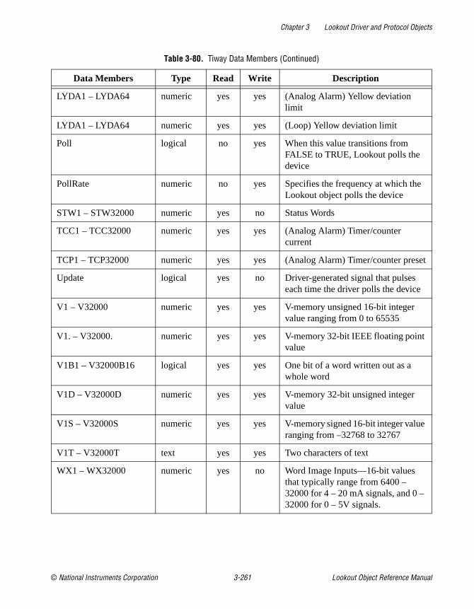
Chapter 3 Lookout Driver and Protocol Objects
© National Instruments Corporation 3-261 Lookout Object Reference Manual
LYDA1 – LYDA64 numeric yes yes (Analog Alarm) Yellow deviation limit
LYDA1 – LYDA64 numeric yes yes (Loop) Yellow deviation limit
Poll logical no yes When this value transitions from FALSE to TRUE, Lookout polls the device
PollRate numeric no yes Specifies the frequency at which the Lookout object polls the device
STW1 – STW32000 numeric yes no Status Words
TCC1 – TCC32000 numeric yes yes (Analog Alarm) Timer/counter current
TCP1 – TCP32000 numeric yes yes (Analog Alarm) Timer/counter preset
Update logical yes no Driver-generated signal that pulses each time the driver polls the device
V1 – V32000 numeric yes yes V-memory unsigned 16-bit integer value ranging from 0 to 65535
V1. – V32000. numeric yes yes V-memory 32-bit IEEE floating point value
V1B1 – V32000B16 logical yes yes One bit of a word written out as a whole word
V1D – V32000D numeric yes yes V-memory 32-bit unsigned integer value
V1S – V32000S numeric yes yes V-memory signed 16-bit integer value ranging from –32768 to 32767
V1T – V32000T text yes yes Two characters of text
WX1 – WX32000 numeric yes no Word Image Inputs—16-bit values that typically range from 6400 – 32000 for 4 – 20 mA signals, and 0 – 32000 for 0 – 5V signals.
Table 3-80. Tiway Data Members (Continued)
Data Members Type Read Write Description

Chapter 3 Lookout Driver and Protocol Objects
Lookout Object Reference Manual 3-262 www.natinst.com
Importing APT Name FilesAfter you have created at least one Tiway object, the Tiway class adds a menu selection to the Lookout Options menu you can use to import an APT name file database for each Tiway object created. You can re-import name files as your APT programs are modified, and Lookout readjusts the aliased name names automatically, in real time.
WY1 – WY32000 numeric yes yes Word Image Outputs—16-bit values that typically range from 6400 – 32000 for 4 –20 mA signals, and 0 – 32000 for 0 – 5V signals.
X1 – X32000 logical yes no Discrete Inputs—unassigned Xs may be used as control registers
Y1 – Y32000 logical yes yes Discrete Outputs—same memory space as Discrete Inputs, so X37 references the same point as Y37. Unassigned Ys may be used as control registers
Table 3-80. Tiway Data Members (Continued)
Data Members Type Read Write Description
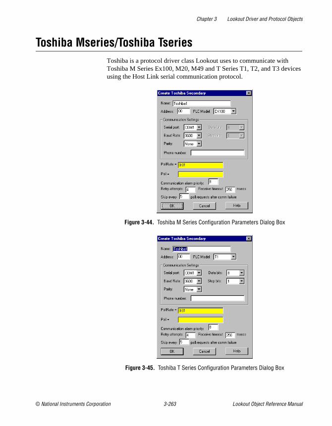
Chapter 3 Lookout Driver and Protocol Objects
© National Instruments Corporation 3-263 Lookout Object Reference Manual
Toshiba Mseries/Toshiba TseriesToshiba is a protocol driver class Lookout uses to communicate with Toshiba M Series Ex100, M20, M49 and T Series T1, T2, and T3 devices using the Host Link serial communication protocol.
Figure 3-44. Toshiba M Series Configuration Parameters Dialog Box
Figure 3-45. Toshiba T Series Configuration Parameters Dialog Box
Chapter 3 Lookout Driver and Protocol Objects
Lookout Object Reference Manual 3-264 www.natinst.com
Address specifies the address of the PLC. The maximum address for a T Series PLC is 32 and for an M Series PLC, 15.
Serial port specifies which COM port the object uses for communicating to the external device. This does not specify the communication type. Communication type is determined by the Options»Serial Ports… command.
Data rate indicates the baud rate that Lookout uses to communicate with the hardware device. The Data rate setting should match the selection made on the physical device.
Data bits indicates the number of data bits that Lookout uses to communicate with the hardware device. The Data bits setting should match the selection made on the physical device.
Stop bits indicates the number of stop bits that Lookout uses to communicate with the hardware device. This setting should match the selection made on the physical device.
Parity indicates the parity that Lookout uses to communicate with the hardware device. This Parity setting should match the selection made on the physical device.
Phone number specifies the number to be dialed if the selected serial port is configured for dial-up. This Phone number only applies to the individual protocol object.
PollRate is a numeric expression that determines how often to poll the device. The object then polls the device at the specified time interval. Normally, this is a simple time constant such as 0:01 (one second). See Numeric Data Members in Chapter 2, How Lookout Works, of the Getting Started with Lookout manual for more information on entering time constants.
Poll is a logical expression. When this expression changes from FALSE to TRUE, Lookout polls the device. You can use a simple expression like the signal from a pushbutton, or a complex algorithm.
Communication alarm priority determines the priority level of alarms generated by the Toshiba object. Such alarms are typically related to communications with the physical device.

Chapter 3 Lookout Driver and Protocol Objects
© National Instruments Corporation 3-265 Lookout Object Reference Manual
Retry attempts specifies the consecutive number of times Lookout attempts to establish communications with a device when it is not getting a valid response. After it tries the number of Retry attempts specified, the Toshiba object generates an alarm and releases the communication port back to the communications subsystem. The subsystem then moves on to the next device in the polling queue (if any). See Chapter 3, Serial Communications, in the Lookout Developer’s Manual for more information.
Receive timeout is the time delay Lookout uses in waiting for a response from a device before retrying the request.
The Skip every… setting instructs Lookout not to poll a device it has lost communication with on every scheduled poll. Instead, Lookout skips the device in the polling cycle. Once communications have been reestablished, the device is polled on its regular cycle.
Toshiba Data MembersA Toshiba object contains a great deal of data. You can read and write to all predefined data points. When you create a Toshiba object, you have immediate access to all the data members for that object.
As with all Lookout drivers, you can access I/O points and other data through data members. The following is a table of data members currently available in the Toshiba object class.
Table 3-81. Toshiba M Series Data Members
Data Member Type Read Write Description
C:0 – C:1536 numeric yes no Counter.
CommFail logical yes no Object-generated signal that is ON if, for any reason, Lookout cannot communicate with the device(s).
D:0, D:1536 numeric yes yes Data register.
Poll logical no yes When this value transitions from FALSE to TRUE Lookout polls the device.
PollRate numeric no yes Lookout expression that determines the device polling frequency.
R:0, R:1024 logical yes yes Auxiliary relay device.

Chapter 3 Lookout Driver and Protocol Objects
Lookout Object Reference Manual 3-266 www.natinst.com
RW:0, RW:64 numeric yes yes Auxiliary relay register.
T:0, T:128 numeric yes yes Timer register.
Update logical yes no Object-generated signal that pulses low each time it polls the device.
Y:0, Y:512 logical yes yes External output device.
YW:0, YW:64 numeric yes yes External output register.
Z:0, Z:512 logical yes yes Link device.
ZW:0, ZW:64 numeric yes yes Link register.
Table 3-82. Toshiba T Series Data Members
Data Member Type Read Write Description
CommFail logical yes no Object-generated signal that is ON if, for any reason, Lookout cannot communicate with the device(s).
D:0, D:1536 numeric yes yes Data register.
Poll logical no yes When this value transitions from FALSE to TRUE Lookout polls the device.
PollRate numeric no yes Lookout expression that determines the device polling frequency.
R:0, R:1024 logical yes yes Auxiliary relay device.
RW:0, RW:64 numeric yes yes Auxiliary relay register.
S:0 – S:1024 logical yes yes Binary timer register.
SW:0 – SW:62 numeric yes yes Data register.
T:0, T:128 numeric yes no Timer register.
Update logical yes no Object-generated signal that pulses low each time it polls the device.
X:0, X:512 logical yes no External input device.
Table 3-81. Toshiba M Series Data Members (Continued)
Data Member Type Read Write Description

Chapter 3 Lookout Driver and Protocol Objects
© National Instruments Corporation 3-267 Lookout Object Reference Manual
Toshiba Status MessagesNo response within timeout period
Lookout received no response from a device within the Receive timeout period. The Toshiba object is able to use the COM port, but when it polls the device, it does not respond—as if it is not even there.
Toshiba errors reported in the response
These errors are reported by the Toshiba device and are in turn reported to the user in text form.
Missing address marker in frame.Invalid address in response.Invalid command in response.Missing BCC marker in frame.Invalid BCC.Missing end of frame marker.
All these alarms indicate a garbled response frame. Check the receive gap or the retry setting in Lookout.
XW:0, XW:64 numeric yes no External input register.
Y:0, Y:512 logical yes yes External output device.
YW:0, YW:64 numeric yes yes External output register.
Table 3-82. Toshiba T Series Data Members (Continued)
Data Member Type Read Write Description

Chapter 3 Lookout Driver and Protocol Objects
Lookout Object Reference Manual 3-268 www.natinst.com
WizdomWizdom is an object class that Lookout uses to communicate with the Wizdom Coprocessor Card. Create one Wizdom object for each Wizdom card installed in the computer.
The Wizdom object scans configured data members for changes 10 times per second.
Wizdom cards are single-board computers. They communicate with the PC through dual-ported memory (that is, RAM accessed by both the PC processor and the Wizdom card processor).
In this example, as shown in the following figure, jumper settings on the card are configured to use hardware interrupt 7 and beginning memory address D000.
Card base address specifies the beginning memory location of the dual ported RAM address. It should match jumper settings on the card. The card uses 8K of physical memory.
When the Wizdom card writes an input value into a memory location, the card generates an interrupt (if so configured), causing the Lookout Wizdom object to immediately scan. This ensures faster responses to field changes.
Note Be sure to verify that no other drivers are mapped to the selected memory location and interrupt.
Note Because the EMM386 memory manager only recognizes the first 4K of mapped memory, it is important to add a memory exclude statement to your computer CONFIG.SYS file as instructed in the card documentation.
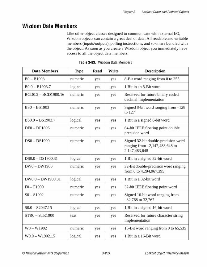
Chapter 3 Lookout Driver and Protocol Objects
© National Instruments Corporation 3-269 Lookout Object Reference Manual
Wizdom Data MembersLike other object classes designed to communicate with external I/O, Wizdom objects can contain a great deal of data. All readable and writable members (inputs/outputs), polling instructions, and so on are bundled with the object. As soon as you create a Wizdom object you immediately have access to all the object data members.
Table 3-83. Wizdom Data Members
Data Members Type Read Write Description
B0 – B1903 numeric yes yes 8-Bit word ranging from 0 to 255
B0.0 – B1903.7 logical yes yes 1 Bit in an 8-Bit word
BCD0.2 – BCD1900.16 numeric yes yes Reserved for future binary coded decimal implementation
BS0 – BS1903 numeric yes yes Signed 8-bit word ranging from –128 to 127
BS0.0 – BS1903.7 logical yes yes 1 Bit in a signed 8-bit word
DF0 – DF1896 numeric yes yes 64-bit IEEE floating point double precision word
DS0 – DS1900 numeric yes yes Signed 32-bit double-precision word ranging from –2,147,483,648 to 2,147,483,648
DS0.0 – DS1900.31 logical yes yes 1 Bit in a signed 32-bit word
DW0 – DW1900 numeric yes yes 32-Bit double-precision word ranging from 0 to 4,294,967,295
DW0.0 – DW1900.31 logical yes yes 1 Bit in a 32-bit word
F0 – F1900 numeric yes yes 32-bit IEEE floating point word
S0 – S1902 numeric yes yes Signed 16-bit word ranging from –32,768 to 32,767
S0.0 – S2047.15 logical yes yes 1 Bit in a signed 16-bit word
STR0 – STR1900 text yes yes Reserved for future character string implementation
W0 – W1902 numeric yes yes 16-Bit word ranging from 0 to 65,535
W0.0 – W1902.15 logical yes yes 1 Bit in a 16-Bit word

Chapter 3 Lookout Driver and Protocol Objects
Lookout Object Reference Manual 3-270 www.natinst.com
Comments The data member addresses listed in the data member table all share the same 4K of memory. For this reason, the following are all the same bit:
B391.5 = W391.5 = DS391.5

© National Instruments Corporation A-1 Lookout Object Reference Manual
ATechnical Support Resources
This appendix describes the comprehensive resources available to you in the Technical Support section of the National Instruments Web site and provides technical support telephone numbers for you to use if you have trouble connecting to our Web site or if you do not have internet access.
NI Web SupportTo provide you with immediate answers and solutions 24 hours a day, 365 days a year, National Instruments maintains extensive online technical support resources. They are available to you at no cost, are updated daily, and can be found in the Technical Support section of our Web site at www.natinst.com/support .
Online Problem-Solving and Diagnostic Resources• KnowledgeBase—A searchable database containing thousands of
frequently asked questions (FAQs) and their corresponding answers or solutions, including special sections devoted to our newest products. The database is updated daily in response to new customer experiences and feedback.
• Troubleshooting Wizards—Step-by-step guides lead you through common problems and answer questions about our entire product line. Wizards include screen shots that illustrate the steps being described and provide detailed information ranging from simple getting started instructions to advanced topics.
• Product Manuals—A comprehensive, searchable library of the latest editions of National Instruments hardware and software product manuals.
• Hardware Reference Database—A searchable database containing brief hardware descriptions, mechanical drawings, and helpful images of jumper settings and connector pinouts.
• Application Notes—A library with more than 100 short papers addressing specific topics such as creating and calling DLLs, developing your own instrument driver software, and porting applications between platforms and operating systems.

Appendix A Technical Support Resources
Lookout Object Reference Manual A-2 www.natinst.com
Software-Related Resources• Instrument Driver Network —A library with hundreds of instrument
drivers for control of standalone instruments via GPIB, VXI, or serial interfaces. You also can submit a request for a particular instrument driver if it does not already appear in the library.
• Example Programs Database—A database with numerous, non-shipping example programs for National Instruments programming environments. You can use them to complement the example programs that are already included with National Instruments products.
• Software Library —A library with updates and patches to application software, links to the latest versions of driver software for National Instruments hardware products, and utility routines.
Worldwide SupportNational Instruments has offices located around the globe. Many branch offices maintain a Web site to provide information on local services. You can access these Web sites from www.natinst.com/worldwide .
If you have trouble connecting to our Web site, please contact your local National Instruments office or the source from which you purchased your National Instruments product(s) to obtain support.
For telephone support in the United States, dial 512 795 8248. For telephone support outside the United States, contact your local branch office:
Australia 03 9879 5166, Austria 0662 45 79 90 0, Belgium 02 757 00 20, Brazil 011 284 5011, Canada (Calgary) 403 274 9391, Canada (Ontario) 905 785 0085, Canada (Québec) 514 694 8521, China 0755 3904939, Denmark 45 76 26 00, Finland 09 725 725 11, France 01 48 14 24 24, Germany 089 741 31 30, Greece 30 1 42 96 427 Hong Kong 2645 3186, India 91805275406, Israel 03 6120092, Italy 02 413091, Japan 03 5472 2970, Korea 02 596 7456, Mexico (D.F.) 5 280 7625, Mexico (Monterrey) 8 357 7695, Netherlands 0348 433466, Norway 32 27 73 00, Singapore 2265886, Spain (Barcelona) 93 582 0251, Spain (Madrid) 91 640 0085, Sweden 08 587 895 00, Switzerland 056 200 51 51, Taiwan 02 2377 1200, United Kingdom 01635 523545

© National Instruments Corporation G-1 Lookout Object Reference Manual
Glossary
Prefix Meanings Value
µ- micro- 10– 6
m- milli- 10–3
k- kilo- 103
M- mega- 106
A
absolute dateabsolute time
Numeric system Lookout uses for keeping track of dates and times, in which midnight (0 hours), January 1, 1900 is represented by 1, midnight of January 2, 1900 is represented by 2, and so on. The absolute date/time number 36234.47222250 represents 11:20 AM, March 15, 1999.
The numeric value for 1 second in Lookout is .000011574, the numeric value for 1 minute is .000694444, and the numeric value for 1 hour is .041666667.
ACK Acknowledge (an alarm or event).
active notification A feature of event-driven software systems in which the application is alerted of value changes when they occur instead of through continuous, loop-driven queries.
address space An OPC term for the area you browse to find what items are available on an OPC server. Part of the standard OPC interface, this space may arrange items hierarchically.
alarm Software notification of a condition in a process. This alarm may call attention of a value that has exceeded or fallen below certain levels, set in the object database or in an Alarm object.

Glossary
Lookout Object Reference Manual G-2 © National Instruments Corporation
alias Name given to a data member using the Edit Database dialog box. This name can be descriptive or mnemonic, and may be associated with other data member configurations such as scaling, logging, and alarming. A data member can have more than one alias, each with different associated configurations.
B
baud rate Measurement of data transmission speed, formally defined as the number of electronic state changes per second. Because most modems transmit four bits of data per change of state, is sometimes misused or misunderstood—a 300 baud modem is moving 1200 bits per second. SeeBPS.
.bmp files Graphic files in bitmap format. If you are using a .bmp file in Lookout, you cannot resize it on screen. See Windows metafile.
BPS Bits per second—measure of the rate of transfer of data.
C
CBL compiler Lookout uses the CBL (Control Block Language) compiler to compile a Lookout source file (.lks ) into a binary file (.l4p ).
.cbx file A Lookout file containing a Lookout object class. A .cbx (Control Block Extension) file may have one or more object classes in it.
checksum A method of verifying that the number of bits received is the same as the number of bits transmitted. Used by TCP/IP and serial protocols.
Citadel The Lookout historical database that stores your data for access later.
classes See object classes.
client A Lookout process that monitors a Lookout server process. Lookout clients should be computer independent so that they can be run from any computer on your network. Lookout server processes run on computers actually connected to your control hardware.
comm port Term sometimes used for a serial port.
connection Input to a Lookout object’s writable data members. For more information, refer to Chapter 4, Using Lookout.

Glossary
© National Instruments Corporation G-3 Lookout Object Reference Manual
control objects Lookout objects you use to control a process, change a data value, adjust a register, and so on.
controllable objects Lookout objects you can control with a Lookout control object.
.csv files Comma Separated Value file, a format widely accepted by spreadsheet and other data handling programs.
CTS Clear to Send. Part of a handshaking protocol for certain devices that connect the serial port of a computer. See the RTS/CTS Handshaking Settings section of Chapter 3, Serial Port Communications, in the Lookout Developer’s Manual for detailed information.
cursor (data table) The Lookout data table can activate one row of data at a time using the data table cursor. See the data table reference in the Lookout online help or the Lookout Object Reference Manual.
D
DAQ Short for Data AcQuisition.
data member Data source or sink associated with a Lookout object. A readable data member, or source, may be used in expressions or as inputs to other objects. A writable data member, or sink, may have at most one connection into it, created using the Object»Edit Connections dialog box. A data member may be both readable and writable. See also native data member and alias.
data type Kind of value (numeric, logical, or text) that a parameter or data member can hold.
database Collection of data stored for later retrieval, display, or analysis.
datagram Message sent between objects in Lookout. A datagram contains a route and a value.
DCOM/COM Distributed Component Object Model, a Microsoft standard in which client program objects request services from server program objects.
The Component Object Model (COM) is a set of interfaces, clients, and servers used to communicate within the same computer (running Windows 98/95 or Windows NT).

Glossary
Lookout Object Reference Manual G-4 © National Instruments Corporation
DDE Dynamic Data Exchange, currently used in Lookout to exchange data with other programs (such as Microsoft Excel) running on your network.
deadband A value that must be exceeded for an alarm to sound or a change in state to be recorded. For instance, if you have a low-level alarm set at 5 with a deadband of 2, the alarm will not trigger until the value being monitored drops to 5. The alarm will then stay active until the value being monitored moves above 7. A deadband keeps small oscillations of value from triggering an alarm and then canceling it too rapidly.
deviation Set a deviation to filter out small changes in value when logging data. Before being logged to a database, a value must change by at least the deviation amount of the last logged value.
dialing prefix Part of the Hayes AT command set for use with modems. See the Dial-Up Modem Settings section of Chapter 3, Serial Port Communications, in the Lookout Developer’s Manual for detailed information.
displayable objects A Lookout object class that has a displayable component, such as a Pot, a Switch, or a Pushbutton.
DLL A Dynamic Link Library, which is a collection of small, special purpose programs which can be called by a larger program running on the computer. Sometimes called Dynamically Linked Library.
driver objects Lookout objects used to communicate with PLCs, RTUs, and other I/O devices.
E
edit mode Lookout mode in which you can alter and create objects within a process. Switch in and out of edit mode by pressing <Ctrl-space> or by selecting Edit»Edit Mode .
engineering unit In Lookout, used to refer to scaled or converted data. Thermocouple data, for instance, arrives in volts as the raw unit, and must be converted to degrees, an engineering unit.
environment services Tasks Lookout performs as a part of making your SCADA/HMI work easier. Lookout environment services include serial communications, database and logging, security, networking, alarming, and so on.
Glossary
© National Instruments Corporation G-5 Lookout Object Reference Manual
Ethernet A widely used, standardized local area networking technology, specified in the IEEE 802.3 standard.
event Anything that happens can be an event. In Lookout, events include such things as adjusting a control value, entering or exiting edit mode, opening or closing a control panel, and logging in or logging out of the system.
expression functions Mathematical, logical, and other functions used by Lookout expressions.
expressions Lookout expressions are often paths to a data member. They can also function like variables that, using a spreadsheet cell type formula, become capable of performing flexible, real-time math operations, condition testing, and other complex operations functions. See Chapter 1, Expressions, in the Lookout Developer’s Manual for more information on expressions.
F
failover A failover is the takeover of a process by a standby computer when the primary computer fails for any reason.
FieldBus An all digital communication network used to connect process instrumentation and control systems.
FieldPoint A National Instruments hardware product line for industrial automation, control, monitoring, and reporting.
frame Sequence of bytes sent from a computer to a device or vice versa. The syntax of the frame depends on the protocol being used. A read frame contains enough information to specify a set of variables whose values the device should return. A write frame specifies a variable in the device and a new value to write into that variable. Some protocols support the writing of multiple variables in a single frame. A response frame is returned from the device to the computer, indicating whether the frame just sent to it was received successfully. If the frame just received was a read frame, the response frame contains a set of requested values.
functionality The way an object works, operates, or performs a task. Functionality is a general concept that applies in the same way to all objects in a given object class. Parameters define the specific functionality of an individual object.
functions See expression functions.

Glossary
Lookout Object Reference Manual G-6 © National Instruments Corporation
G
gray proximity A term used in Lookout color animation. This sets what percentage of gray will be replaced by a given color as conditions change in a monitored value or set of values.
H
Hi and HiHi Alarm settings. Both warn that a value has gone above some setpoint. Generally a Hi alarm is used to alert an operator of a need for intervention. A hihi alarm is usually used to alert an operator that the value has been exceeded by an even greater margin than a hi alarm indicates, and is usually used to indicate an urgent need for action.
historical logging The process of storing data in a database for use at another time, or from another location.
HOA Hand-Off-Auto control, used to set whether a value must be changed manually, is completely turned off, or functions automatically. You can use a Pot object and a complex expression to create this sort of control in Lookout, or you can use a RadioButton object, depending on the particular requirements of the task you need to accomplish.
I
I/O point Every read-only, write-only, or read-write connection Lookout makes to external hardware is counted as an I/O point. Lookout is licensed for use with a set number of I/O points. If you exceed the number you are licensed to use with your copy of Lookout, a warning message appears on your computer screen warning you to shut down one of your processes within a specified time before Lookout cuts back on I/O usage.
(implicit) data member A Lookout data member containing the fundamental data for certain object classes. When you make a connection to an (implicit) data member, you only use the name of the object, not the name of the object followed by the data member name.

Glossary
© National Instruments Corporation G-7 Lookout Object Reference Manual
L
.l4p files File extension for Lookout process files. These are the compiled files Lookout runs when it runs a process.
.l4t files File extension for a Lookout state file, which stores the values for Lookout controls and other objects with state information.
.lka files File extension for Lookout security files.
.lkp files File extension for Lookout process files in versions of Lookout earlier than Lookout 4.
.lks files File extension for a Lookout source file, which Lookout compiles to make a Lookout process file that Lookout can run. This is the file you should make sure you keep backed up in case you need to recreate a corrupted process file, or in case some future version of Lookout cannot run a process file compiled in an earlier version of Lookout.
logging The process of storing data in a computer database file. See Chapter 7, Logging Data and Events, in the Lookout Developer’s Manual for more information on logging data in Lookout.
logical data member A Lookout data member of the logical data type.
.lst files Extension for the Lookout state file in versions of Lookout earlier than Lookout 4.
M
multiplex A method of working with more than one data stream using only one communications channel. There are a number of different methods of multiplexing, depending on the hardware and software being used. A number of Lookout driver objects support multiplexing hardware.
Glossary
Lookout Object Reference Manual G-8 © National Instruments Corporation
N
native data member Data members built into a Lookout object class, as opposed to data members you create by using aliases.
NetDDE A way of networking using DDE (dynamic data exchange), retained in Lookout 4 and later for compatibility with earlier versions of Lookout.
numeric data member A Lookout data member of the numeric data type.
O
object A specific instance created from an object class.
object classes Software modules you use to create individual objects to perform tasks in Lookout.
object connections Software links between objects used to transmit data and commands from one object to another.
ODBC Open DataBase Connectivity, a standard application programming interface (API) for accessing a database. You can use ODBC statements to access files in a number of different databases, including Access, dBase, DB2, and Excel.
ODBC is compatible with the Structured Query Language (SQL) Call-Level Interface. ODBC handles SQL requests by converting them into requests an ODBC database can use.
OPC OLE for Process Control, an industry standard interface providing interoperability between disparate field devices, automation/control systems, and business systems. Based on ActiveX, OLE, Component Object Model (COM), and Distributed COM (DCOM) technologies.
P
parameter Input to an object, similar to a writable data member, whose value is specified in the object parameter list in a Lookout source (.lks ) file. Typically, parameter values are set in the object Object»Create or Object»Modify dialog box.

Glossary
© National Instruments Corporation G-9 Lookout Object Reference Manual
ping A small utility program in Windows and DOS that checks to see if a computer can be reached across a network. Also used to indicate the running of that program.
pixel Picture Element, the smallest bit of a picture. Has one color or shade of grey. The number of pixels per inch determine the resolution of an image.
PLC Programmable Logic Controller.
poll A software event in which a computer checks some value in a device or register. In Lookout, a logical command that forces a device poll to check data member values.
poll rate How often a device is polled.
pop-up panel One variety of Lookout control panel that can only be displayed at the size set by the process developer, and which cannot be maximized. When open, a popup panel remains on top of other panels until minimized.
process In Lookout, process refers to a Lookout “program,” used for industrial automation, control, monitoring, or reporting.
process file The Lookout binary file Lookout executes when running a process. Carries the .l4p extension.
R
raw unit Data as it arrives in your process, such as voltage or amperage. Thermocouple data, for instance, arrives in volts as the raw unit, and must be converted to degrees, an engineering unit.
receive gap A serial communications setting that determines the number of empty bytes (or amount of time) a driver receives before recognizing the end of a message frame and requesting another message. See the Setting Receive Gap section of Chapter 3, Serial Communications, in the Lookout Developer’s Manual for more information about the receive gap.
redundancy A system for making sure that a computer can come online and run a Lookout process if the computer currently running that process fails for some reason.

Glossary
Lookout Object Reference Manual G-10 © National Instruments Corporation
remote In the context of Lookout, remote is a position source location for a control. See the Remote Position Source Connections section of Chapter 4, Using Lookout, for detailed information on the Lookout remote position source.
resolution The smallest signal increment that can be detected by a measurement system. Also, the number of pixels per inch on a computer monitor screen or dots per inch in printer output.
RTS Request to Send, part of a handshaking protocol for certain devices that connect the serial port of a computer. See the RTS/CTS Handshaking Settings section of Chapter 3, Serial Communications, in the Lookout Developer’s Manual for detailed information.
RTU Remote Terminal Unit, a device similar to a PLC for use at a remote location, communicating with a host system through radio or telephonic connections.
run mode Lookout mode in which processes run but no editing changes can be made. Switch in and out of run mode by pressing <Ctrl-space> or selecting Edit»Edit Mode .
S
SCXI Signal Conditioning eXtensions for Instrumentation, a National Instruments product line for conditioning low-level signals.
security accounts Also called user and group accounts, Lookout uses security accounts to define what users or group of users have different operation privileges in Lookout. See Chapter 6, Security, in the Lookout Developer’s Manual for detailed information on Lookout security.
server A process that provides data (services) to client processes. In Lookout, server processes are intended to be run on one computer only, with direct connections to field hardware. Client processes interact with field hardware through server processes.
source file Lookout file that can be compiled to produce a binary Lookout process file that runs a process. Uses a .lks file extension.
SQL Structured Query Language, used to get information from and update information in a database.

Glossary
© National Instruments Corporation G-11 Lookout Object Reference Manual
standby A computer standing by to take over running a process if the primary computer fails or falls offline.
startup file A Lookout process file (.l4p ) you designate in the System Options dialog box that Lookout will open and run any time Lookout is opened.
state file The Lookout file that stores the value of all Lookout control parameters and object data members in use in a process. Uses the file extension .l4t .
system objects Lookout objects used to control other objects or process and analyze data.
T
TCPTCP/IP
Transmission Control Protocol, a method (protocol) for sending data between computers. Used with IP, the Internet Protocol.
TCP/IP sends data as packets, with IP handling the delivery of data and TCP keeping track of the individual packets.
text data member Lookout data member used for text data.
trace A term for data from a single source over some period of time, stored in an ODBC-compliant database.
traces table ODBC databases present data in the form of traces tables. A traces table contains a field or column of data for each data member being logged, along with a field you can use to query the database.
trend Historical data showing the change in a value over time. Often used in connection with graphing the data for display.
W
.wav files File extension given to sound files. You can play a .wav file in Lookout to add sounds or speech to alarms or events.
Windows metafile A standard graphics file type for use in the Microsoft Windows operating environment. If you use a metafile graphic in Lookout, you can enlarge or reduce it on the screen, use them as masks without specifying transparent pixels, and use the Lookout Animator to animate the colors of the graphic.
.wmf file File extension given to Windows Metafile graphic files.

Glossary
Lookout Object Reference Manual G-12 © National Instruments Corporation
X
.xls file File extension given to Microsoft Excel files.

© National Instruments Corporation I-1 TitleShort-Hidden (cross reference text)
Index
AAB object classes (AB_PLC2, AB_PLC5,
AB_SLC500), 3-2 to 3-23Allen-Bradley Parameters dialog box,
3-3 to 3-4communication with Allen-Bradley
controllersPLC-2 family, 3-2PLC-5 family, 3-2SLC-500 family, 3-2 to 3-3
data members, 3-10 to 3-17AB_PLC2 (table), 3-10 to 3-11AB_PLC5 (table), 3-14 to 3-17AB_SLC500 (table), 3-11 to 3-14
DH+ interface parameters, 3-5 to 3-8error messages, 3-18 to 3-23Ethernet interface parameters, 3-8 to 3-9serial port interface parameters, 3-4using 5136-SD card from S-S Technologies,
Inc., 3-9Accumulator object class, 2-2 to 2-3
data members (table), 2-3Definition Parameters dialog box, 2-2description, 2-2
AdvantechPCL object class, 3-24 to 3-25data members (table), 3-25Definition Parameters dialog box, 3-24
$Alarm global object, 2-7 to 2-9data members (table), 2-8 to 2-9description, 2-7 to 2-8Edit Connections dialog box, 2-7using with other objects, 2-9
Alarm object class, 2-4 to 2-6data members (table), 2-6typical settings
logical style alarm, 2-4numeric style alarm, 2-5
alarmsNational Instruments Fieldbus,
3-137 to 3-141Philips object class, 3-189 to 3-192S5_3964 object class, 3-221 to 3-222S5_AS511 object class, 3-226 to 3-227
Allen-Bradley PLC controllers. See AB object classes
Alternator object class, 2-10 to 2-15Command and Advance data members,
2-12 to 2-13connecting, 2-12data members (table), 2-11Definition Parameters dialog box,
2-10 to 2-11Delay between device starts parameter, 2-13description, 2-10 to 2-11ElapsedTime data member, 2-14Hand - Off - Auto modes, 2-13 to 2-14Maximum run time parameter, 2-13RunTime data member, 2-14status messages, 2-14 to 2-15
Animator object class, 2-16 to 2-20color animations, 2-18 to 2-20creating moving animations, 2-17 to 2-18data members (table), 2-20Select graphic dialog box, 2-16
Applicom object classes, 3-26 to 3-51corresponding protocols/devices (table),
3-27 to 3-28data members, 3-28 to 3-45
April 1000 (table), 3-30JBUS (table), 3-28 to 3-29Klockner-Moeller (table), 3-30 to 3-31local (table), 3-28Otic Fischer & Porter (table),
3-31 to 3-32Profibus DP (table), 3-32 to 3-33

Index
TitleShort-Hidden (cross reference text) I-2 www.natinst.com
Profibus FMS (table), 3-33 to 3-34Profibus L2 (table), 3-34 to 3-36S5 H1 (table), 3-36 to 3-38SAIA SBus (table), 3-38Siemens H1 (table), 3-43 to 3-44Siemens S5 AS511 (table),
3-39 to 3-40Siemens S7 MPI (table), 3-40 to 3-42Siemens S7 PPI (table), 3-42 to 3-43Telemecanique (table), 3-45
Definition Parameters dialog boxes, 3-26 to 3-27
general information on using drivers, 3-45 to 3-48
configuration of Applicom server, 3-47
creating cyclic functions, 3-48loading Applicom server, 3-47local and image modes, 3-46testing Applicom server,
3-47 to 3-48special instructions for local object class,
3-48 to 3-49status messages, 3-49 to 3-51
APT tag file, importing, 3-262Aquatrol object class, 3-52 to 3-56
data membersDefinition Parameters dialog box,
3-52 to 3-53RTU Configuration dialog box,
3-53 to 3-54status messages, 3-55 to 3-56
data members (table), 3-54 to 3-55ASCII object class, 3-57 to 3-66
See also IPASCII object classdata members (table), 3-58 to 3-59Definition Parameters dialog box,
3-57 to 3-58error messages, 3-66request and response format strings,
3-60 to 3-65
entering format string, 3-64markers, 3-61 to 3-63request frame construction examples,
3-64response format examples,
3-64 to 3-65using sum data members, 3-65
Average object class, 2-21 to 2-22data members (table), 2-21definition Parameters dialog box, 2-21
Ccolors
animations, 2-18 to 2-20comma-separated value (.CSV) files
SqlExec object class, 2-185connecting objects
Alternator object class, 2-12signals, DataTable object class,
2-29 to 2-32control panels
See also Panel object classDataTables example
display panel, 2-33multiplexing displays and graphics,
2-26 to 2-27operating multiplexed panel, 2-34
conventions used in this manual, xixCounter object class, 2-23
data members (table), 2-23Definition Parameters dialog box, 2-23
.CSV (comma-separated values) files, 2-185cursors, for DataTables, 2-34 to 2-36
multiple, 2-36Cutler-Hammer object class, 3-67 to 3-71
data members (table), 3-69 to 3-70Definition Parameters dialog box, 3-67status messages, 3-70 to 3-71

Index
© National Instruments Corporation I-3 TitleShort-Hidden (cross reference text)
Ddata members
AB object classes (tables), 3-10 to 3-17AB_PLC2 object class, 3-10 to 3-11AB_PLC5 object class, 3-14 to 3-17AB_SLC500 object class, 3-11 to 3-14Accumulator object class, 2-3AdvantechPCL object class, 3-25$Alarm global object, 2-8 to 2-9Alarm object class, 2-6Alternator object class, 2-11Animator object class, 2-20Applicom object classes
April 1000, 3-30JBUS, 3-28 to 3-29Klockner-Moeller, 3-30 to 3-31local, 3-28Otic Fischer & Porter, 3-31 to 3-32Profibus DP, 3-32 to 3-33Profibus FMS, 3-33 to 3-34Profibus L2, 3-34 to 3-36S5 AS511, 3-39 to 3-40S5 H1, 3-36 to 3-38S7 MPI, 3-40 to 3-42SAIA SBus, 3-38Siemens H1, 3-43 to 3-44Siemens S7 PPI, 3-42 to 3-43Telemecanique, 3-45
Aquatrol object class, 3-54 to 3-55ASCII object class, 3-58 to 3-59Average object class, 2-21Counter object class, 2-23Cutler-Hammer object class, 3-69 to 3-70DataTable object class, 2-37 to 2-39DdeLink object class, 2-41DdeTable object class, 2-45DelayOff object class, 2-47DelayOn object class, 2-49DeltaTau object class, 3-73Derivative object class, 2-51
DialGauge object class, 2-54DL205 and DL405 object classes,
3-77 to 3-78DNP object class, 3-81 to 3-83Dynamic object class, 3-87 to 3-90ElapsedTime object class, 2-55Event object class, 2-56Expression object class, 2-58FisherROC object class, 3-93 to 3-95Flipflop object class, 2-59Gauge object class, 2-61GE_Series90 object class, 3-100 to 3-101Histogram object class, 2-64 to 2-65Hitachi object class, 3-105 to 3-106HyperTrend object class, 2-73 to 2-74Integral object class, 2-76Interpolate object class, 2-80Interval object class, 2-82IPASCII object class, 3-108 to 3-109Junction object class, 2-83$Keyboard global object, 2-85L3Pot object class, 2-89 to 2-90L3Pushbutton object class, 2-94L3Switch object class, 2-97L3TextEntry object class, 2-100LatchGate object class, 2-101Loader object class, 2-104 to 2-105Maximum object class, 2-107Minimum object class, 2-109Mitsubishi object class, 3-118MitsubishiFX object class,
3-118 to 3-119Modbus object class, 3-128 to 3-131ModbusMOSCAD object class,
3-132 to 3-133ModbusSlave object class, 3-135 to 3-136Monitor object class, 2-111Multistate object class, 2-112National Instruments Fieldbus,
3-139 to 3-140

Index
TitleShort-Hidden (cross reference text) I-4 www.natinst.com
National Instruments FieldPoint, 3-144 to 3-145
National Instruments FieldPoint, multiple discrete, 3-146
National Instruments Lookout OPC Client Driver (table), 3-154
Neutralzone object class, 2-115NIDAQDevice object class, 3-157NISCXI object class, 3-161 to 3-162Omron object class, 3-167OneShot object class, 2-117OptoHostWords object class,
3-172 to 3-174OptoMistic object class, 3-180 to 3-181Optomux object class, 3-186Pager object class, 2-120Panel object class, 2-129 to 2-130Pareto object class, 2-135 to 2-136Philips object class, 3-191PID object class, 2-141Pipe object class, 2-142Playwave object class, 2-143Pot object class (table), 2-146 to 2-147Profibus DP object class, 3-195ProfibusL2 object class, 3-202 to 3-203Pulse object class, 2-150Pushbutton object class (table),
2-154 to 2-155RadioButton object class, 2-159Recipe object class, 2-165 to 2-166Reliance object class, 3-206RKC F object class, 3-209Run object class, 2-168S5_3964 object class, 3-219 to 3-221S5_AS511 object class, 3-224 to 3-226Sample object class, 2-169SampleText object class, 2-171Scale object class, 2-173Sequencer object class, 2-176SiemensTI505 object class,
3-231 to 3-235
Sixnet object class, 3-238 to 3-240Spinner object class, 2-177Spreadsheet object class, 2-182SqlExec object class, 2-184SquareD object class, 3-248 to 3-249summing, in ASCII object, 3-65Switch object class (table),
2-192 to 2-193$System global object class, 2-197Tesco object class, 3-252 to 3-253TextEntry object class (table),
2-200 to 2-201Timeofxxxx object class, 2-203Tiway object class, 3-259 to 3-262Toshiba Mseries/Toshiba Tseries,
3-265 to 3-267Wizdom object class, 3-269XBarR object class, 2-207 to 2-209XChart object class, 2-211 to 2-213XYChart object class, 2-215 to 2-216
DataTable object class, 2-24 to 2-39connecting signals, 2-29 to 2-31
to cells, 2-30to columns, 2-31
cursors, 2-34 to 2-36data members (table), 2-37 to 2-39Definition Parameters dialog box,
2-24 to 2-25example, 2-28 to 2-33
connecting signals, 2-29 to 2-31display panel, 2-33reading cell value back to Lookout
object, 2-32multiple cursors, 2-36multiplexing displays and graphics,
2-26 to 2-27operating your multiplexed panel, 2-34SQL queries
SQL queries, DataTable, 2-26DdeLink object class, 2-40 to 2-41
data members (table), 2-41

Index
© National Instruments Corporation I-5 TitleShort-Hidden (cross reference text)
Definition Parameters dialog box, 2-40 to 2-41
remote computer, 2-40 to 2-41same computer, 2-40
DdeTable object class, 2-42 to 2-45data members (table), 2-45Definition Parameters dialog box,
2-42 to 2-44remote computer, 2-44same computer, 2-42 to 2-44
DelayOff object class, 2-46 to 2-47data members (table), 2-47Definition Parameters dialog box, 2-46Display Parameters dialog box, 2-47
DelayOn object class, 2-48 to 2-49data members (table), 2-49Definition Parameters dialog box, 2-48Display Parameters dialog box, 2-49
DeltaTau object class, 3-72 to 3-73configuration parameters, 3-72data members (table), 3-73
Derivative object class, 2-50 to 2-51data members (table), 2-51Definition Parameters dialog box,
2-50 to 2-51DH+ interface parameters, AB object classes,
3-5 to 3-8DialGauge object class, 2-52 to 2-54
data members (table), 2-54Definition Parameters dialog box, 2-52Display Parameters dialog box, 2-53
DL205 and DL405 object classes, 3-74 to 3-79
data members (table), 3-77 to 3-78Definition Parameters dialog box,
3-74 to 3-75, 3-80 to 3-81status messages, 3-78 to 3-79
DNP object class, 3-80 to 3-84data members (table), 3-81 to 3-83error messages, 3-83 to 3-84
documentation
conventions used in this manual, xixrelated documentation, xx
Dynamic object class, 3-85 to 3-90configuration Parameters dialog box,
3-86 to 3-87data members (table), 3-87 to 3-90
EEdit Connections dialog box
$Alarm global object, 2-7$Keyboard global object, 2-84
ElapsedTime object class, 2-55data members (table), 2-55Definition Parameters dialog box, 2-55
error mesagesDNP object class, 3-83 to 3-84
error messagesSee also status messagesASCII object class, 3-66IPASCII object class, 3-114 to 3-115NIDAQDevice object class, 3-158NISCXI object class, 3-163OptoMistic object class, 3-182SquareD object class, 3-249
Ethernet interface parameters, AB object classes, 3-8 to 3-9
Event object class, 2-56data members (table), 2-56Definition Parameters dialog box, 2-56
Expression object class, 2-57 to 2-58Create Expression dialog box, 2-57data members (table), 2-58
FFieldbus. See National Instruments FieldbusFieldPoint object class. See National
Instruments FieldPointFisherROC object class, 3-91 to 3-97
data members (table), 3-93 to 3-95

Index
TitleShort-Hidden (cross reference text) I-6 www.natinst.com
Definition Parameters dialog box, 3-91 to 3-92
status messages, 3-96 to 3-97Flipflop object class, 2-59
data members (table), 2-59Definition Parameters dialog box, 2-59
format strings. See ASCII object class; IPASCII object class
GGauge object class, 2-60 to 2-61
data members (table), 2-61Definition Parameters dialog box,
2-60 to 2-61Display Parameters dialog box, 2-61
GE_Series90 object class, 3-98 to 3-102data members (table), 3-100 to 3-101Definition Parameters dialog box,
3-98 to 3-99status messages, 3-101 to 3-102
global object classes$Alarm global object, 2-7 to 2-9$Keyboard global object, 2-84 to 2-86$System global object, 2-197
graphicsanimating. See Animator object classmultiplexing displays and graphics, using
Datatables, 2-26 to 2-27
HHand - Off - Auto modes, Alternator object
class, 2-13 to 2-14Histogram object class, 2-62 to 2-65
data members (table), 2-64 to 2-65Definition Parameters dialog box,
2-62 to 2-63Hitachi object class, 3-103 to 3-106
data members (table), 3-105 to 3-106
Defintion Parameters dialog box, 3-103 to 3-104
status messages, 3-106HOA. See Hand - Off - AutoHyperTrend object class, 2-66 to 2-74
data members (table), 2-73 to 2-74
IIntegral object class, 2-75 to 2-76
data members (table), 2-76Definition Parameters dialog box,
2-75 to 2-76Interpolate object class, 2-77 to 2-80
data members (table), 2-80Definition Parameters dialog box, 2-77
Interval object class, 2-81 to 2-82data members (table), 2-82Definition Parameters dialog box, 2-81Display Parameters dialog box, 2-81
IPASCII object class, 3-107 to 3-115See also ASCII object classdata members (table), 3-108 to 3-109data types allowed (table), 3-111Definition Parameters dialog box,
3-107 to 3-108entering format string, 3-113error messages, 3-114 to 3-115markers, 3-110 to 3-112request and response format strings,
3-109 to 3-110request frame construction examples,
3-113 to 3-114response format examples,
3-113 to 3-114
JJunction object class, 2-83
data members (table), 2-83Definition Parameters dialog box, 2-83

Index
© National Instruments Corporation I-7 TitleShort-Hidden (cross reference text)
K$Keyboard global object, 2-84 to 2-86
data members (table), 2-85description, 2-84Edit Connections dialog box, 2-84
KT cards. See AB object classes
LL3Pot object class, 2-87 to 2-90
data members (table), 2-89 to 2-90Definition Parameters dialog box,
2-87 to 2-88Display Parameters dialog box,
2-88 to 2-89L3Pushbutton object class, 2-91 to 2-94
data members (table), 2-94Definition Parameters dialog box,
2-91 to 2-93Display Parameters dialog box, 2-93Verification Message dialog box, 2-92
L3Switch object class, 2-95 to 2-97action verification, 2-95data members (table), 2-97Definition Parameters dialog box,
2-95 to 2-96displaying
graphics for switches, 2-96Verification Message dialog box,
2-95L3TextEntry object class, 2-98 to 2-100
data members (table), 2-100Display Parameters dialog box, 2-99Parameters dialog box, 2-98 to 2-99
LatchGate object class, 2-101data members (table), 2-101Definition Parameters dialog box, 2-101
Loader object class, 2-102 to 2-106data members (table), 2-104 to 2-105status messages, 2-105 to 2-106
Lookout
National Instruments data acquisition devices supported (table), 3-159
SCXI devices supported (table), 3-164
MMaximum object class, 2-107 to 2-108
data members (table), 2-107Definition Parameters dialog box, 2-107
Minimum object class, 2-109 to 2-110data members (table), 2-109Definition Parameters dialog box, 2-109
Mitsubishi and MitsubishiFX object classes, 3-116 to 3-120
Configuration Parameters dialog box, 3-116 to 3-117
data membersMitsubishi (table), 3-118MitsubishiFX (table), 3-118 to 3-119
Mitsubishi models supported, 3-120status messages, 3-119 to 3-120
Modbus and ModbusMOSCAD object classes, 3-121 to 3-133
advanced parameters, 3-124 to 3-126Configuration Parameters dialog box,
3-122 to 3-124data members
6-digit address coding (table), 3-128Modbus (table), 3-128 to 3-131ModbusMOSCAD (table),
3-132 to 3-133Modbus Protocol Statistics,
3-126 to 3-127overview, 3-121
ModbusSlave object class, 3-134 to 3-136Confirmation Parameters dialog box,
3-135data members (table), 3-135 to 3-136overview, 3-134
Monitor object class, 2-111data members (table), 2-111

Index
TitleShort-Hidden (cross reference text) I-8 www.natinst.com
multiplexing displays and graphics, using DataTables, 2-26 to 2-27
Multistate object class, 2-112 to 2-113Configuration Parameters dialog box,
2-112data members (table), 2-112
NNational Instruments data acquisition devices
supported by Lookout (table), 3-159National Instruments Fieldbus, 3-137 to 3-141
alarms, 3-139Configuration Parameters dialog box,
3-138 to 3-139data members (table), 3-139 to 3-140overview, 3-137status messages, 3-140troubleshooting, 3-141
National Instruments Fieldpoint, 3-142 to 3-149
Configuration Parameters dialog box, 3-142 to 3-144
data members (table), 3-144 to 3-145multiple discrete data members
(table), 3-146error messages, 3-147 to 3-149multiple discrete data members,
3-146 to 3-147National Instruments Lookout OPC Client
Driver, 3-150 to 3-155Configuration Parameters dialog box,
3-150 to 3-151OPC item ID format, 3-154 to 3-155
National Instruments Web support, A-1Neutralzone object class, 2-114 to 2-115
data members (table), 2-115Definition Parameters dialog box, 2-114
NIDAQDevice object class, 3-156 to 3-159Configuration Parameters dialog box,
3-156 to 3-157
data members (table), 3-157error messages, 3-158National Instruments data acquisition
devices supported (table), 3-159NIDAQ.INI file, 3-157 to 3-158
NIDAQ.INI file configurationNIDAQDevice object class,
3-157 to 3-158NISCXI, 3-162 to 3-163
NISCXI object class, 3-160 to 3-164configuring NIDAQ.INI for NISCXI,
3-162 to 3-163channel attributes, 3-162cold-junction sensor attributes, 3-163
data members (table), 3-161 to 3-162Definition Parameters dialog box,
3-160 to 3-161error messages, 3-163SCXI devices supported (table), 3-164
Oobject classes
See also individual object classes, e.g., Animator object
alphabetical list, 1-1 to 3-270object databases
See also data membersobject parameters
See also individual object classes, e.g., Animator object
objectsconnecting
Alternator object class, 2-12signals, DataTable object class,
2-29 to 2-32Omron object class, 3-165 to 3-168
data members (table), 3-167Definition Parameters dialog box,
3-165 to 3-166models supported, 3-168

Index
© National Instruments Corporation I-9 TitleShort-Hidden (cross reference text)
status messages, 3-168OneShot object class, 2-116 to 2-117
data members (table), 2-117Definition Parameters dialog box,
2-116 to 2-117Display Parameters dialog box, 2-117
online problem-solving and diagnostic resources, A-1
OPC Client Driver. See National Instruments Lookout OPC Client Driver
OptoHostWords object class, 3-169 to 3-178Configuring the Hostwords controller,
3-171data members (table), 3-172 to 3-174HostWords errors, 3-175 to 3-178Lookout driver errors with
OptoHostWords, 3-175OptoHost Definition Parameters dialog
box: Serial, 3-169 to 3-170OptoHostWords Definition Parameters
dialog box: Ethernet, 3-171status messages, 3-174TCP/IP errors, 3-175
OptoMistic object class, 3-179 to 3-182data members (table), 3-180 to 3-181error messages, 3-182OptoMistic Parameter Definition dialog
box, 3-179 to 3-180Optomux object class, 3-183 to 3-188
data members (table), 3-186Definition Parameters dialog box,
3-183 to 3-184status messages, 3-187 to 3-188watchdog capability, 3-185
PPager object class, 2-118 to 2-121
Alphanumeric Definition Parameters dialog box, 2-118 to 2-119
data members (table), 2-120
Numeric Only Definition Parameters dialog box, 2-118 to 2-119
object modesAlphanumeric, 2-120 to 2-121Numeric Only, 2-120serial port settings, 2-120 to 2-121
queueing, 2-121status messages, 2-121
Panel object class, 2-122 to 2-130data members (table), 2-129 to 2-130Definition and Display Parameters dialog
box, 2-122 to 2-125“home panel” considerations, 2-127manipulating panels, 2-125printing, 2-127 to 2-128screen resolution and graphics, 2-128switching between panels, 2-125 to 2-127
Pareto object class, 2-131 to 2-136data members (table), 2-135 to 2-136Definition Parameters dialog box,
2-131 to 2-132Display Parameters dialog box, 2-132incrementing factor counts, 2-134weighted or unweighted charts,
2-133 to 2-134Philips object class, 3-189 to 3-192
alarms, 3-192Configuration Parameters dialog box,
3-189 to 3-190data members (table), 3-191status messages, 3-192
PID object class, 2-137 to 2-141data members (table), 2-141Definition Parameters dialog box,
2-137 to 2-139positional control, 2-140velocity control, 2-140
Pipe object class, 2-142data members (table), 2-142Definition Parameters dialog box, 2-142
Playwave object class, 2-143

Index
TitleShort-Hidden (cross reference text) I-10 www.natinst.com
data members (table), 2-143Definition Parameters dialog box, 2-143
PLCsSee also AB object classes
Popup control panelsparameter settings, 2-122 to 2-123
Popup no icon control panels, 2-123Pot object class, 2-144 to 2-148
data members (table), 2-146 to 2-147Definition Parameters dialog box,
2-144 to 2-146Display Parameters dialog box, 2-146
printingpanels, 2-127 to 2-128
Profibus DP object class, 3-193 to 3-196Configuration Parameters dialog box,
3-194configuring DP network, 3-193data members (table), 3-195PFB card settings, 3-194 to 3-195requirements for running, 3-193 to 3-194status messages, 3-196
ProfibusL2 object class, 3-197 to 3-203Configuration Parameters dialog box,
3-200 to 3-201data members (table), 3-202 to 3-203Lookout messaging system, 3-197PFB card settings, 3-201 to 3-202requirements, 3-200 to 3-202sample program, 3-198 to 3-200
DB1 configuration, 3-198 to 3-199detailed explanation, 3-198function block explanation,
3-199 to 3-200status messages, 3-203
Pulse object class, 2-149 to 2-150data members (table), 2-150Definition Parameters dialog box, 2-149Display Parameters dialog box, 2-150
Pushbutton object class, 2-151 to 2-155data members (table), 2-154 to 2-155
Definition Parameters dialog box, 2-151 to 2-154
Display Parameters dialog box, 2-154Verification Message dialog box, 2-152
RRadioButton object class, 2-156 to 2-159
data members (table), 2-159RadioButton Definition Parameters
dialog box, 2-156 to 2-158RadioButton Display Parameters dialog
box, 2-158 to 2-159RadioButton Display Parameters dialog
box with custom graphics chosen, 2-158
Recipe object class, 2-160 to 2-166data members (table), 2-165 to 2-166Definition Parameters dialog box,
2-161 to 2-162Display Parameters dialog box, 2-164example, 2-160 to 2-161file selection dialog box (figure), 2-162omitting ingredients (comment), 2-166reloading files for changed recipe (note),
2-163related documentation, xxReliance object class, 3-204 to 3-206
data members (table), 3-206Definition Parameters dialog box,
3-204 to 3-205destination settings, 3-205PC-Link card settings, 3-205status messages, 3-206
request and response format stringsASCII object class, 3-60 to 3-65
entering format string, 3-64object markers, 3-61 to 3-63request frame construction examples,
3-64

Index
© National Instruments Corporation I-11 TitleShort-Hidden (cross reference text)
response format examples, 3-64 to 3-65
IPASCII object class, 3-107 to 3-115entering format string, 3-113markers, 3-110 to 3-112request frame construction examples,
3-113 to 3-114response format examples,
3-113 to 3-114RKC F Series object class, 3-207 to 3-216
data members (tables), 3-209 to 3-215Lookout data members, 3-215measured value group, 3-210memory area and set value group,
3-211operation mode group, 3-210parameter group 10 (measured input
parameters), 3-211parameter group 11 (remote setting
input parameters), 3-211parameter group 12 (output
parameters), 3-212parameter group 13 (auto-tuning bias
parameters), 3-212parameter group 14 (alarm 1
parameters), 3-212parameter group 15 (analog output
parameters), 3-213parameter group 16 (positioning,
proportioning, PID action parameters), 3-213
parameter group 17 (bar graph parameter), 3-213
parameter group 20 (input selection parameters), 3-213 to 3-214
parameter group 21 (setting parameters), 3-214
parameter group 22 (output action parameters), 3-214
parameter group 23 (alarm 2 parameters), 3-214 to 3-215
parameter group 40 (data lock parameters), 3-215
RKC data member group, 3-209Definition Parameters dialog box,
3-207 to 3-208RKC models supported, 3-216status messages, 3-216
RTU Configuration dialog box, Aquatrol object class, 3-53 to 3-54
Run object class, 2-167 to 2-168data members (table), 2-168Definition Parameters dialog box, 2-167
SS5_3964 object class, 3-217 to 3-222
alarms, 3-221 to 3-222data members (table), 3-219 to 3-221Definition Parameters dialog box,
3-217 to 3-218S5_AS511 object class, 3-223 to 3-227
alarms, 3-226 to 3-227Object alarms, 3-226PLC alarms, 3-227
data members (table), 3-224 to 3-226Definition Parameters dialog box,
3-223 to 3-224Sample object class, 2-169 to 2-170
data members (table), 2-169Definition Parameters dialog box, 2-169
SampleText object class, 2-171data members (table), 2-171Definition Parameters dialog box, 2-171
Scale object class, 2-172 to 2-173data members (table), 2-173Definition Parameters dialog box, 2-172Display Parameters dialog box, 2-173
SCXI devices supported (table), 3-164See also NISCXI object class
securityPanel object class, 2-122 to 2-130

Index
TitleShort-Hidden (cross reference text) I-12 www.natinst.com
viewing securityPanel object class, 2-122 to 2-130
Select graphic dialog box, Animator object class, 2-16
Sequencer object class, 2-174 to 2-176data members (table), 2-176Programming the Sequencer,
2-175 to 2-176Sequencer Definition Parameters dialog
box, 2-174 to 2-175serial port interface parameters
AB object class, 3-4SquareD object class, 3-243
Siemens H1. See SiemensTI505Siemens Simatic S5 PLCs. See S5_3964
object classSiemensTI505 object class, 3-228 to 3-235
configuring HI-TF, 3-229 to 3-231data members (table), 3-231 to 3-235Definition Parameters dialog box,
3-228 to 3-229status messages, 3-235
Sixnet object class, 3-236 to 3-241Configuration Parameters dialog box,
3-236 to 3-237data members (table), 3-238 to 3-240importing Sixtags database, 3-240status messages, 3-241
software-related resources, A-2Spinner object class, 2-177 to 2-178
data members (table), 2-177Definition Parameters dialog box, 2-177
Spreadsheet object class, 2-179 to 2-182Configuration Parameters dialog box,
2-179 to 2-182data members (table), 2-182
SqlExec object class, 2-183 to 2-189comma separated value (CSV) file
support, 2-185comments, 2-185 to 2-186
Configuration Parameters dialog box, 2-183
data members (table), 2-184sample DNS and SQL strings,
2-185 to 2-186SQL commander buffering,
2-187 to 2-188status messages, 2-188 to 2-189
SquareD object class, 3-242 to 3-249data members (table), 3-248 to 3-249Definition Parameters dialog box,
3-242 to 3-243error messages, 3-249serial port interface parameters, 3-243SY/ENET interface parameters,
3-245 to 3-246SY/LINK interface parameters,
3-244 to 3-245Using ST/ENET with more than one
Ethernet board in system, 3-246 to 3-248
S-S 5136-SD card, 3-9status messages
See also error messagesAlternator object class, 2-14 to 2-15Applicom object class, 3-49 to 3-51Aquatrol object class, 3-55 to 3-56Cutler-Hammer object class, 3-70 to 3-71DL205 and DL405 object classes,
3-78 to 3-79FisherROC object class, 3-96 to 3-97GE_Series90 object class, 3-101 to 3-102Hitachi object class, 3-106Loader object class, 2-105 to 2-106Mitsubishi and MitsubishiFX object
classes, 3-119 to 3-120National Instruments Fieldbus, 3-140Omron object class, 3-168OptoHostWords object class, 3-174Optomux object class, 3-187 to 3-188Pager object class, 2-121

Index
© National Instruments Corporation I-13 TitleShort-Hidden (cross reference text)
Philips object class, 3-192Profibus DP object class, 3-196ProfibusL2 object class, 3-203Reliance object class, 3-206RKC F Series object class, 3-216SiemensTI505, 3-235Sixnet object class, 3-241SqlExec object class, 2-188 to 2-189Toshiba Mseries/Toshiba Tseries, 3-267
sum data members, ASCII object, 3-65Switch object class, 2-190 to 2-193
action verification, 2-190data members (table), 2-192 to 2-193Definition Parameters dialog box,
2-190 to 2-192displaying
graphics for switches, 2-192Verification Message dialog box,
2-190Symbolic Link, 2-194 to 2-196$System global object, 2-197
data members (table), 2-197description, 2-197
TTCP/IP errors, OptoHostWords object class,
3-175technical support resources, A-1telephone support, A-2Tesco object class, 3-250 to 3-253
Configuration Parameters dialog box, 3-250 to 3-251
data members (table), 3-252 to 3-253TextEntry object class, 2-198 to 2-201
data members (table), 2-200 to 2-201Display Parameters dialog box, 2-200Parameters dialog box, 2-198 to 2-200
TimeOfxxxx object class, 2-202 to 2-203data members (table), 2-203Definition Parameters dialog box, 2-202
Display Parameters dialog box, 2-203Tiway object class, 3-254 to 3-262
communication techniques, 3-255 to 3-258
CTI TCP/IP, 3-258local port, 3-255Unilink Host Adapter,
3-256 to 3-257Unilink PC Adapter, 3-257 to 3-258
Configuration Parameters dialog box, 3-254 to 3-255
data members (table), 3-259 to 3-262importing APT tag files, 3-262
Toshiba Mseries/Toshiba Tseries, 3-263 to 3-267
Configuration Parameter dialog boxes, 3-263 to 3-265
data members (tables), 3-265 to 3-267status messages, 3-267
Vviewing security
control panels, 2-123
WWeb support from National Instruments
online problem-solving and diagnostic resources, A-1
software-related resources, A-2Wizdom object class, 3-268 to 3-270
configuring, 3-268data members (table), 3-269
worldwide technical support, A-2
XXBarR object class, 2-204 to 2-209
data members (table), 2-207 to 2-209

Index
TitleShort-Hidden (cross reference text) I-14 www.natinst.com
Definition Parameters dialog box, 2-204 to 2-205
Display Parameters dialog box, 2-205R chart (figure), 2-206X-bar chart (figure), 2-206
XChart object class, 2-210 to 2-213data members (table), 2-211 to 2-213Definition Parameters dialog box, 2-210Display Parameters dialog box, 2-211
XYChart object class, 2-214 to 2-216data members (table), 2-215 to 2-216Definition Parameters dialog box,
2-214 to 2-215Display Parameters dialog box, 2-215


