18
HARDWARE INSTALLATION GUIDE Arcserve UDP 8100 and UDP 8200 Appliance Hardware Installation Guide
HARDWARE INSTALLATION GUIDE
Arcserve UDP 8100 and UDP 8200Appliance Hardware Installation Guide
Arcserve UDP 8100 and UDP 8200 Appliance Hardware Installation Guide 2
Section 1 Safety Notice and Warnings . . . . . . . . . . . . . . . . . . . . . . . . . . . . . . . . . . . . . . . . . . . 3
Section 2 Ratings . . . . . . . . . . . . . . . . . . . . . . . . . . . . . . . . . . . . . . . . . . . . . . . . . . . . . . . . . . 3
Section 3 Electrical and General Safety Guidelines . . . . . . . . . . . . . . . . . . . . . . . . . . . . . . . . . . 4
Section 4 Site Preparation . . . . . . . . . . . . . . . . . . . . . . . . . . . . . . . . . . . . . . . . . . . . . . . . . . . . 6
Section 5 Unpacking the 4-Post Rack Installation Assemblies . . . . . . . . . . . . . . . . . . . . . . . . . . 7
Section 6A 4-Post Rack Installation with Standard Rails . . . . . . . . . . . . . . . . . . . . . . . . . . . . . . . . 8
Section 6B 4-Post Rack Installation with Quick Mount Rails (square hole rack only) . . . . . . . . . . . 9
Section 7 Installing the Appliance in the 4-Post Rack . . . . . . . . . . . . . . . . . . . . . . . . . . . . . . . . 10
Section 8 Unpacking the 2-Post Rack Installation Hardware . . . . . . . . . . . . . . . . . . . . . . . . . . . 11
Section 9 2-Post Rack Installation . . . . . . . . . . . . . . . . . . . . . . . . . . . . . . . . . . . . . . . . . . . . . . 12
Section 10 Installing the Appliance in the 2-Post Rack . . . . . . . . . . . . . . . . . . . . . . . . . . . . . . . . 13
Section 11 Rear Panel Connections . . . . . . . . . . . . . . . . . . . . . . . . . . . . . . . . . . . . . . . . . . . . . . 14
Section 12 Front Panel Operation . . . . . . . . . . . . . . . . . . . . . . . . . . . . . . . . . . . . . . . . . . . . . . . 16
Section 13 Run Arcserve UDP Appliance Wizard . . . . . . . . . . . . . . . . . . . . . . . . . . . . . . . . . . . . . 16
Section 14 Access Arcserve UDP . . . . . . . . . . . . . . . . . . . . . . . . . . . . . . . . . . . . . . . . . . . . . . . . 17
Section 15 Contact Support . . . . . . . . . . . . . . . . . . . . . . . . . . . . . . . . . . . . . . . . . . . . . . . . . . . 17
Section 16 Warranty Information . . . . . . . . . . . . . . . . . . . . . . . . . . . . . . . . . . . . . . . . . . . . . . . . 17
Table of Contents
Arcserve UDP 8100 and UDP 8200 Appliance Hardware Installation Guide 3
1. Safety Notice and Warnings
2. Ratings
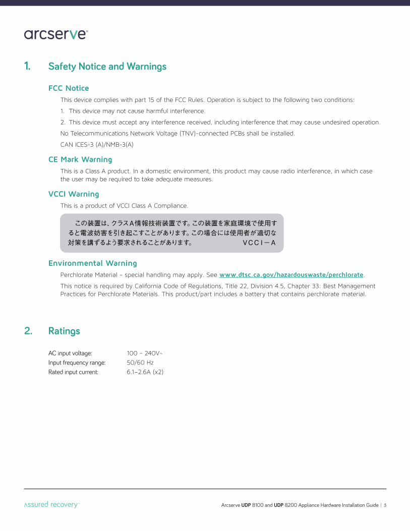
FCC NoticeThis device complies with part 15 of the FCC Rules. Operation is subject to the following two conditions:
1. This device may not cause harmful interference.
2. This device must accept any interference received, including interference that may cause undesired operation.
No Telecommunications Network Voltage (TNV)-connected PCBs shall be installed.
CAN ICES-3 (A)/NMB-3(A)
CE Mark WarningThis is a Class A product. In a domestic environment, this product may cause radio interference, in which case the user may be required to take adequate measures.
VCCI WarningThis is a product of VCCI Class A Compliance.
Environmental WarningPerchlorate Material - special handling may apply. See www.dtsc.ca.gov/hazardouswaste/perchlorate.
This notice is required by California Code of Regulations, Title 22, Division 4.5, Chapter 33: Best Management Practices for Perchlorate Materials. This product/part includes a battery that contains perchlorate material.
AC input voltage: 100 - 240V~
Input frequency range: 50/60 Hz
Rated input current: 6.1-2.6A (x2)
Arcserve UDP 8100 and UDP 8200 Appliance Hardware Installation Guide 4
3. Electrical and General Safety Guidelines
CAUTIONThis appliance is intended for installation in restricted areas only. Initial setup and maintenance should be performed by qualified personnel.
CAUTIONPower down the appliance following the operating system’s proper power down procedure from the frontpanel. Unplug the AC power cord(s) before servicing.
CAUTIONTo avoid electrical shock, check the power cords as follows:n This product is to be installed in Restricted Access Location only.
n Use the exact type of power cords required.
n Use power cord(s) that came with safety certifications.
n Power cord(s) must comply with AC voltage requirements in your region.
n The power cord plug cap must have an electrical current rating that is at least 125% of the electrical current rating of this product.
n The power cord plug cap that plugs into the AC receptacle on the power supply must be an IEC 320, sheet C13,type female connector.
n Plug the power cord(s) into a socket that is properly grounded before turning on the power.
CAUTIONRequired operating conditions for the appliance are -
n Temperature: 10 to 35oC.
n Humidity, non-condensing: 8 to 90%.
CAUTIONCLASS 1 LASER PRODUCTAPPAREIL À LASER DE CLASSE 1
DISPOSING OF BATTERY BACKUP UNITS - IF APPLICABLEWARNINGIf the BBU is damaged in any way, toxic chemicals may be released.
The material in the battery pack contains heavy metals that can contaminate the environment. Federal, state,and local regulations prohibit the disposal of rechargeable batteries in public landfills. Be sure to recycle theold battery packs properly. Comply with all applicable battery disposal and hazardous material handling lawsand regulations in the country or other jurisdiction where you are using the BBU.
WARNINGRisk of explosion if the battery is installed upside down or is replaced by an incorrect type. Replace it only with the same or equivalent type recommended by the manufacturer. Dispose of used batteries according to the instructions.
Arcserve UDP 8100 and UDP 8200 Appliance Hardware Installation Guide 5
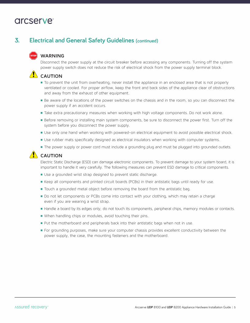
3. Electrical and General Safety Guidelines (continued)
WARNINGDisconnect the power supply at the circuit breaker before accessing any components. Turning off the systempower supply switch does not reduce the risk of electrical shock from the power supply terminal block.
CAUTIONn To prevent the unit from overheating, never install the appliance in an enclosed area that is not properly
ventilated or cooled. For proper airflow, keep the front and back sides of the appliance clear of obstructions and away from the exhaust of other equipment.
n Be aware of the locations of the power switches on the chassis and in the room, so you can disconnect the power supply if an accident occurs.
n Take extra precautionary measures when working with high voltage components. Do not work alone.
n Before removing or installing main system components, be sure to disconnect the power first. Turn off the system before you disconnect the power supply.
n Use only one hand when working with powered-on electrical equipment to avoid possible electrical shock.
n Use rubber mats specifically designed as electrical insulators when working with computer systems.
n The power supply or power cord must include a grounding plug and must be plugged into grounded outlets.
CAUTIONElectric Static Discharge (ESD) can damage electronic components. To prevent damage to your system board, it isimportant to handle it very carefully. The following measures can prevent ESD damage to critical components.
n Use a grounded wrist strap designed to prevent static discharge.
n Keep all components and printed circuit boards (PCBs) in their antistatic bags until ready for use.
n Touch a grounded metal object before removing the board from the antistatic bag.
n Do not let components or PCBs come into contact with your clothing, which may retain a charge even if you are wearing a wrist strap.
n Handle a board by its edges only; do not touch its components, peripheral chips, memory modules or contacts.
n When handling chips or modules, avoid touching their pins.
n Put the motherboard and peripherals back into their antistatic bags when not in use.
n For grounding purposes, make sure your computer chassis provides excellent conductivity between the power supply, the case, the mounting fasteners and the motherboard.
Arcserve UDP 8100 and UDP 8200 Appliance Hardware Installation Guide 6
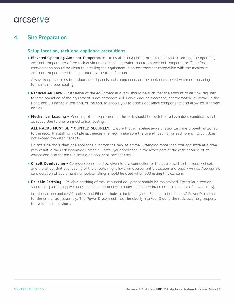
Setup location, rack and appliance precautionsn Elevated Operating Ambient Temperature - If installed in a closed or multi-unit rack assembly, the operating
ambient temperature of the rack environment may be greater than room ambient temperature. Therefore, consideration should be given to installing the equipment in an environment compatible with the maximum ambient temperature (Tma) specified by the manufacturer.
Always keep the rack’s front door and all panels and components on the appliances closed when not servicing to maintain proper cooling.
n Reduced Air Flow - Installation of the equipment in a rack should be such that the amount of air flow required for safe operation of the equipment is not compromised. Leave enough clearance, approximately 25 inches in the front, and 30 inches in the back of the rack to enable you to access appliance components and allow for sufficient air flow.
n Mechanical Loading - Mounting of the equipment in the rack should be such that a hazardous condition is not achieved due to uneven mechanical loading.
ALL RACKS MUST BE MOUNTED SECURELY. Ensure that all leveling jacks or stabilizers are properly attached to the rack. If installing multiple appliances in a rack, make sure the overall loading for each branch circuit does not exceed the rated capacity.
Do not slide more than one appliance out from the rack at a time. Extending more than one appliance at a time may result in the rack becoming unstable. Install your appliance in the lower part of the rack because of its weight and also for ease in accessing appliance components.
n Circuit Overloading - Consideration should be given to the connection of the equipment to the supply circuit and the effect that overloading of the circuits might have on overcurrent protection and supply wiring. Appropriate consideration of equipment nameplate ratings should be used when addressing this concern.
n Reliable Earthing - Reliable earthing of rack-mounted equipment should be maintained. Particular attention should be given to supply connections other than direct connections to the branch circuit (e.g. use of power strips).
Install near appropriate AC outlets, and Ethernet hubs or individual jacks. Be sure to install an AC Power Disconnect for the entire rack assembly. The Power Disconnect must be clearly marked. Ground the rack assembly properly to avoid electrical shock.
4. Site Preparation
Quick-mount rack rail assembly, inside view
Quick-mount rack rail assembly, outside view
Adjustable front quick-mount rack rail assembly(attaches to the front of the rack)
Adjustable rear quick-mount rack rail assembly(attaches to the rear of the rack)
Arcserve UDP 8100 and UDP 8200 Appliance Hardware Installation Guide 7
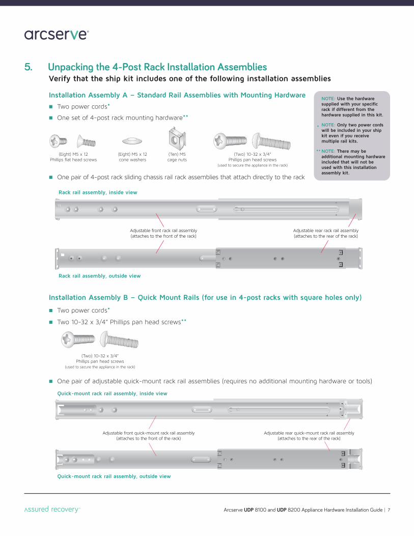
5. Unpacking the 4-Post Rack Installation AssembliesVerify that the ship kit includes one of the following installation assemblies
Installation Assembly A - Standard Rail Assemblies with Mounting Hardware
n Two power cords*
n One set of 4-post rack mounting hardware**
n One pair of 4-post rack sliding chassis rail rack assemblies that attach directly to the rack
Installation Assembly B - Quick Mount Rails (for use in 4-post racks with square holes only)
n Two power cords*
n Two 10-32 x 3/4” Phillips pan head screws**
n One pair of adjustable quick-mount rack rail assemblies (requires no additional mounting hardware or tools)
Rack rail assembly, outside view
Rack rail assembly, inside view
Adjustable front rack rail assembly(attaches to the front of the rack)
Adjustable rear rack rail assembly(attaches to the rear of the rack)
(Eight) M5 x 12Phillips flat head screws
(Two) 10-32 x 3/4”Phillips pan head screws
(used to secure the appliance in the rack)
(Eight) M5 x 12cone washers
(Ten) M5cage nuts
NOTE: Use the hardwaresupplied with your specificrack if different from thehardware supplied in this kit.
NOTE: Only two power cordswill be included in your shipkit even if you receive multiple rail kits.
NOTE: There may be additional mounting hardwareincluded that will not be used with this installation assembly kit.
*
**
(Two) 10-32 x 3/4”Phillips pan head screws
(used to secure the appliance in the rack)
Arcserve UDP 8100 and UDP 8200 Appliance Hardware Installation Guide 8
Adjustable rack rail assemblies
4-post rack
Emptyhole
Emptyhole
Emptyhole
Rear section ofthe adjustablerack rail assembly
Rack bracket tab
Rack bracket tabs
Front section ofthe adjustablerack rail assembly
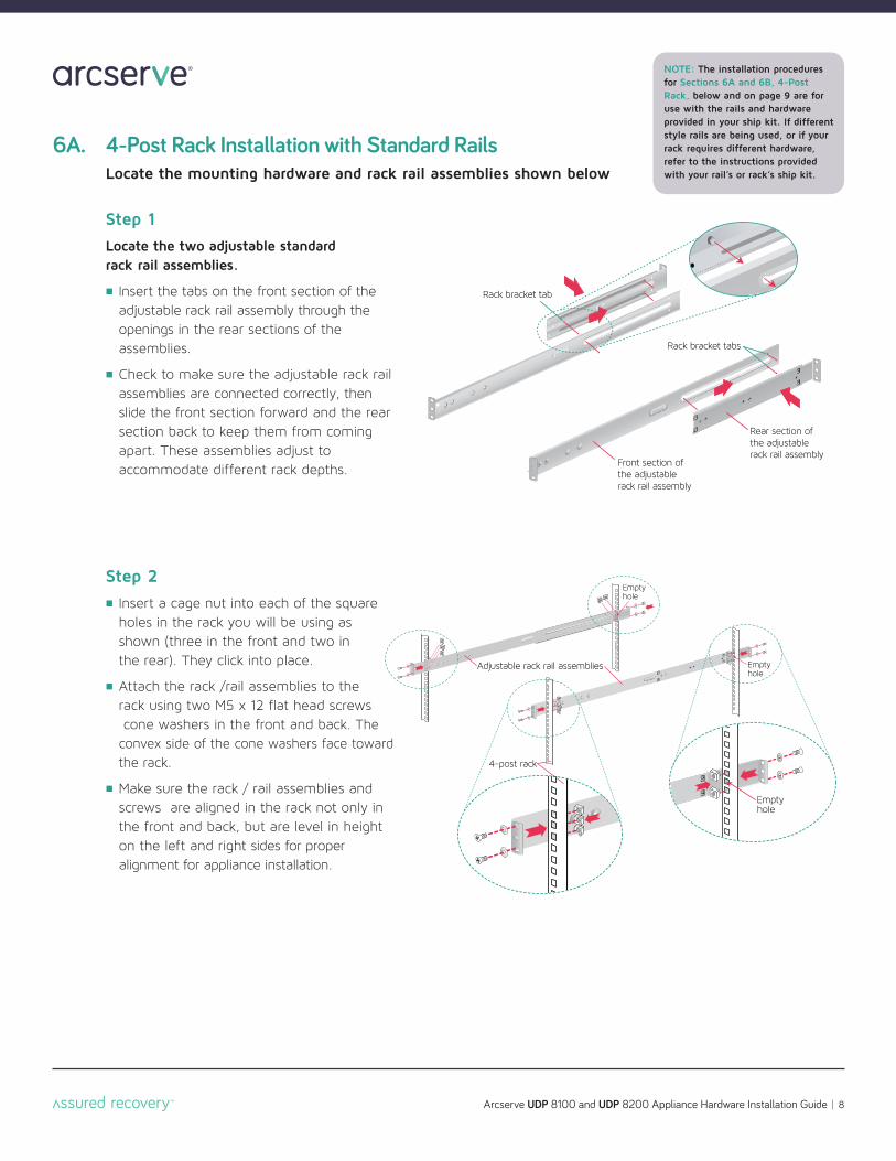
6A. 4-Post Rack Installation with Standard RailsLocate the mounting hardware and rack rail assemblies shown below
Step 2n Insert a cage nut into each of the square
holes in the rack you will be using as
shown (three in the front and two in
the rear). They click into place.
n Attach the rack /rail assemblies to the
rack using two M5 x 12 flat head screws
cone washers in the front and back. The
convex side of the cone washers face toward
the rack.
n Make sure the rack / rail assemblies and
screws are aligned in the rack not only in
the front and back, but are level in height
on the left and right sides for proper
alignment for appliance installation.
Step 1Locate the two adjustable standard rack rail assemblies.
n Insert the tabs on the front section of the
adjustable rack rail assembly through the
openings in the rear sections of the
assemblies.
n Check to make sure the adjustable rack rail assemblies are connected correctly, then
slide the front section forward and the rear
section back to keep them from coming
apart. These assemblies adjust to
accommodate different rack depths.
NOTE: The installation proceduresfor Sections 6A and 6B, 4-PostRack, below and on page 9 are foruse with the rails and hardware provided in your ship kit. If differentstyle rails are being used, or if yourrack requires different hardware,refer to the instructions providedwith your rail’s or rack’s ship kit.
Arcserve UDP 8100 and UDP 8200 Appliance Hardware Installation Guide 9
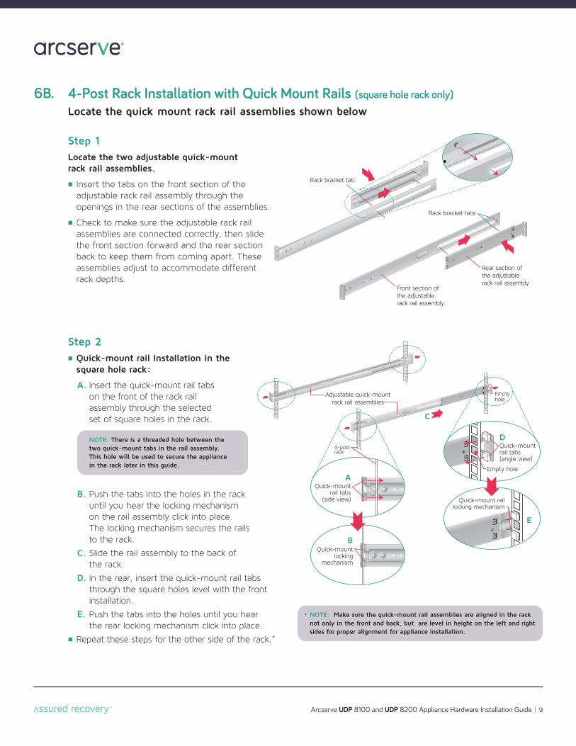
6B. 4-Post Rack Installation with Quick Mount Rails (square hole rack only)Locate the quick mount rack rail assemblies shown below
Rear section ofthe adjustablerack rail assembly
Rack bracket tab
Rack bracket tabs
Front section ofthe adjustablerack rail assembly
Step 1Locate the two adjustable quick-mount rack rail assemblies.
n Insert the tabs on the front section of the adjustable rack rail assembly through the openings in the rear sections of the assemblies.
n Check to make sure the adjustable rack railassemblies are connected correctly, then slide the front section forward and the rear section back to keep them from coming apart. These assemblies adjust to accommodate different rack depths.
Quick-mountlocking
mechanism
Adjustable quick-mountrack rail assemblies
Emptyhole
Empty hole
Quick-mount rail tabs(angle view)
Quick-mountrail tabs
(side view) Quick-mount raillocking mechanism
4-postrack
D
C
E
A
B
NOTE: Make sure the quick-mount rail assemblies are aligned in the racknot only in the front and back, but are level in height on the left and rightsides for proper alignment for appliance installation.
Step 2n Quick-mount rail Installation in the
square hole rack:
A. Insert the quick-mount rail tabs on the front of the rack rail assembly through the selected set of square holes in the rack.
B. Push the tabs into the holes in the rack until you hear the locking mechanism on the rail assembly click into place. The locking mechanism secures the rails to the rack.
C. Slide the rail assembly to the back of the rack.
D. In the rear, insert the quick-mount rail tabs through the square holes level with the front installation.
E. Push the tabs into the holes until you hear the rear locking mechanism click into place.
n Repeat these steps for the other side of the rack.*
NOTE: There is a threaded hole between thetwo quick-mount tabs in the rail assembly.This hole will be used to secure the appliancein the rack later in this guide.
*
Adjustable rack rail assemblies(standard or quick-mount)
Fixed chassis rail(attached prior to shipment)
Locking tab
Two 10-32 x 3/4” Phillips flat-head screws*
Arcserve UDP 8100 and UDP 8200 Appliance Hardware Installation Guide 10
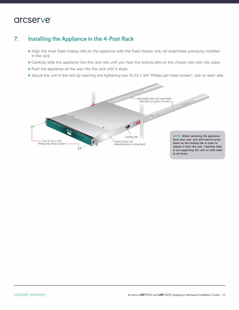
7. Installing the Appliance in the 4-Post Rack
n Align the inner fixed chassis rails on the appliance with the fixed chassis rack rail assemblies previously installed in the rack.
n Carefully slide the appliance into the rack rails until you hear the locking tabs on the chassis rails click into place.
n Push the appliance all the way into the rack until it stops.
n Secure the unit in the rack by inserting and tightening two 10-32 x 3/4” Phillips pan head screws*, one on each side.
NOTE: When removing the appliancefrom your rack, you will need to pressdown on the locking tab in order to release it from the rack. Carefully slideit out supporting the unit on both sidesat all times.
4 (Four)Fixed 2-post rack brackets
Inside front view Outside front view
2 (Two)Fixed 2-post rack brackets
with threaded holes
Inside front view Outside front view
Arcserve UDP 8100 and UDP 8200 Appliance Hardware Installation Guide 11
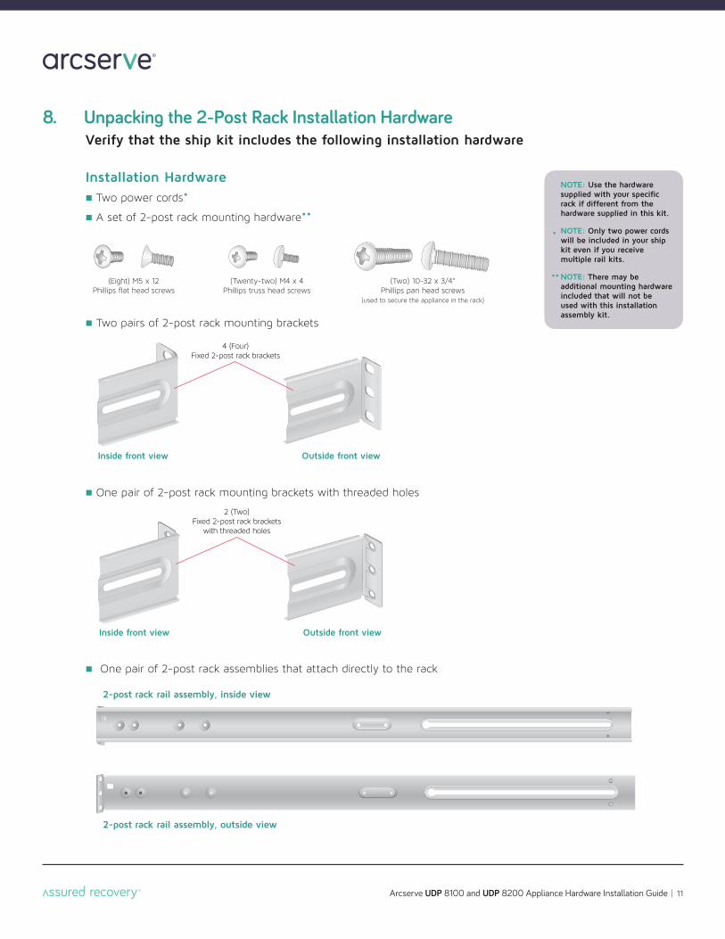
8. Unpacking the 2-Post Rack Installation HardwareVerify that the ship kit includes the following installation hardware
Installation Hardware n Two power cords*
n A set of 2-post rack mounting hardware**
n Two pairs of 2-post rack mounting brackets
n One pair of 2-post rack mounting brackets with threaded holes
n One pair of 2-post rack assemblies that attach directly to the rack
2-post rack rail assembly, outside view
2-post rack rail assembly, inside view
(Eight) M5 x 12Phillips flat head screws
(Two) 10-32 x 3/4”Phillips pan head screws
(used to secure the appliance in the rack)
(Twenty-two) M4 x 4Phillips truss head screws
NOTE: Use the hardwaresupplied with your specificrack if different from thehardware supplied in this kit.
NOTE: Only two power cordswill be included in your shipkit even if you receive multiple rail kits.
NOTE: There may be additional mounting hardwareincluded that will not be used with this installation assembly kit.
*
**
Small fixedrack brackets
Long bracket
C
B
Two M4 truss head screws
One M4 trusshead screw
B Small fixedrack brackets
Small fixedrack brackets with
threaded holes
A
A
C
Arcserve UDP 8100 and UDP 8200 Appliance Hardware Installation Guide 12
M5 x 12 flat head screws*(two front and two rear)
A
A
A
A
B
B
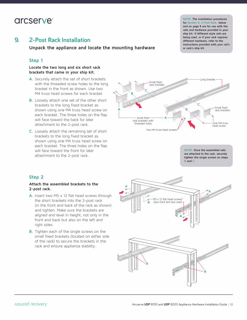
9. 2-Post Rack InstallationUnpack the appliance and locate the mounting hardware
Step 1Locate the two long and six short rackbrackets that came in your ship kit.
A. Securely attach the set of short brackets with the threaded screw holes to the long bracket in the front as shown. Use two M4 truss head screws for each bracket.
B. Loosely attach one set of the other short brackets to the long fixed bracket as shown using one M4 truss head screw on each bracket. The three holes on the flap will face toward the back for later attachment to the 2-post rack.
C. Loosely attach the remaining set of short brackets to the long fixed bracket as shown using one M4 truss head screw on each bracket. The three holes on the flap will face toward the front for later attachment to the 2-post rack.
Step 2Attach the assembled brackets to the 2-post rack.
A. Insert two M5 x 12 flat head screws through the short brackets into the 2-post rack (in the front and back of the rack as shown) and tighten. Make sure the brackets are aligned and level in height, not only in the front and back but also on the left and right sides.
B. Tighten each of the single screws on the small fixed brackets (located on either side of the rack) to secure the brackets in the rack and ensure appliance stability.
NOTE: Once the assembled rails are attached to the rack, securelytighten the single screws on steps B and C.
NOTE: The installation proceduresfor Section 9, 2-Post Rack, belowand on page 9 are for use with therails and hardware provided in yourship kit. If different style rails arebeing used, or if your rack requiresdifferent hardware, refer to the instructions provided with your rail’sor rack’s ship kit.
Arcserve UDP 8100 and UDP 8200 Appliance Hardware Installation Guide 13
Two 10-32 x 3/4” Phillips flat-head screws*
Fixed chassis rail(attached prior to shipment)
Locking tab
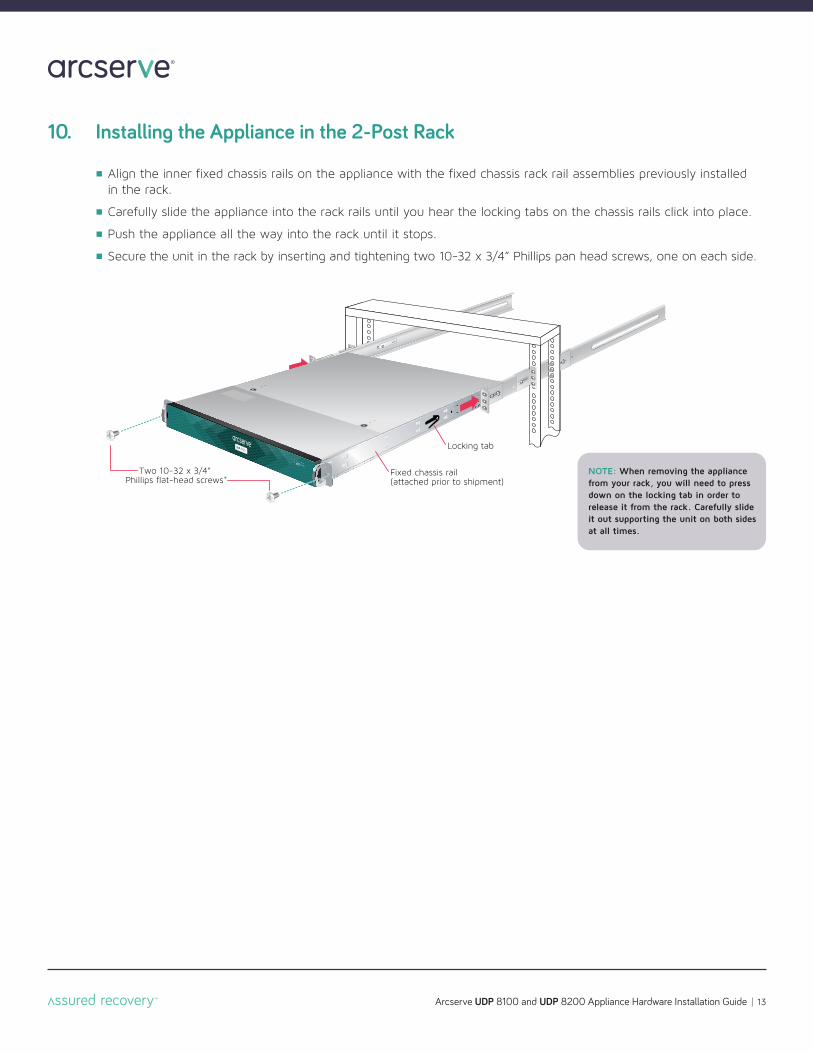
10. Installing the Appliance in the 2-Post Rack
n Align the inner fixed chassis rails on the appliance with the fixed chassis rack rail assemblies previously installed in the rack.
n Carefully slide the appliance into the rack rails until you hear the locking tabs on the chassis rails click into place.
n Push the appliance all the way into the rack until it stops.
n Secure the unit in the rack by inserting and tightening two 10-32 x 3/4” Phillips pan head screws, one on each side.
NOTE: When removing the appliancefrom your rack, you will need to pressdown on the locking tab in order to release it from the rack. Carefully slideit out supporting the unit on both sidesat all times.
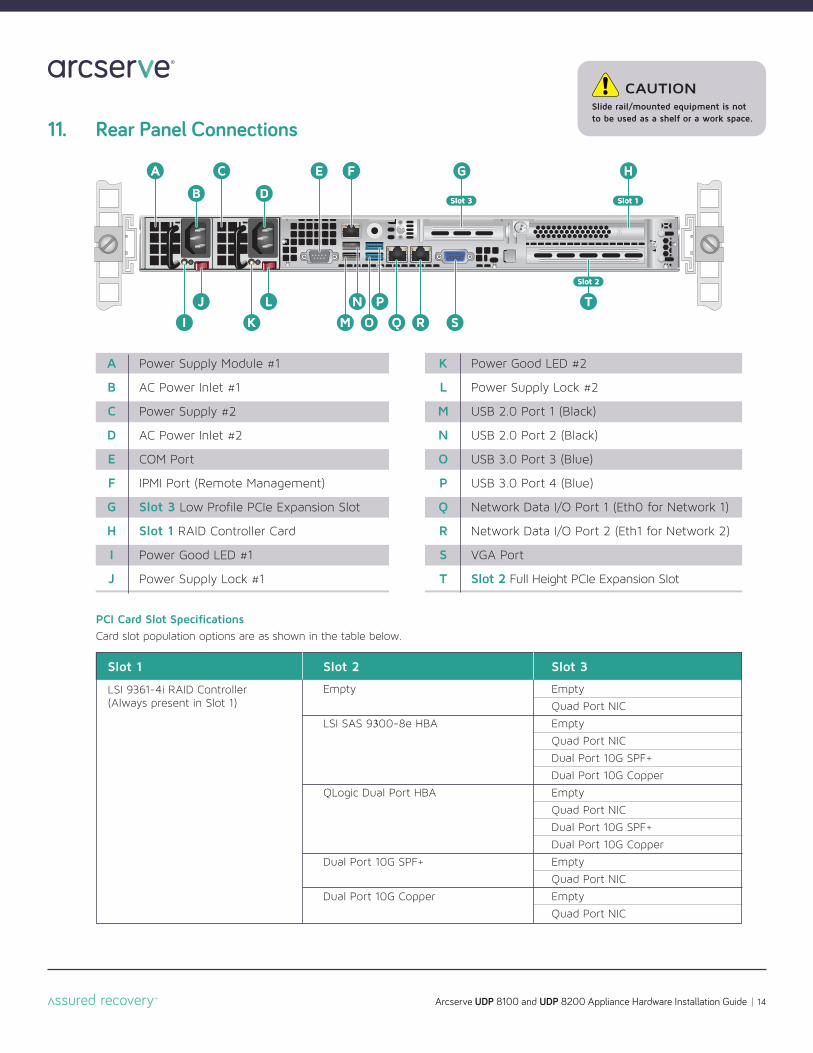
11. Rear Panel Connections
A C
I
J
K Q R S
L
M
N
O
P T
F
B D
F G H
Slot 2
E F
Slot 1Slot 3
A C E F G H
I
J
B
K Q
L
M
N
O
P
D
R S
3toSl
T
2toSl
1toSl
CAUTIONSlide rail/mounted equipment is not to be used as a shelf or a work space.
Arcserve UDP 8100 and UDP 8200 Appliance Hardware Installation Guide 14
A
B
C
D
E
F
G
H
I
J
Power Supply Module #1
AC Power Inlet #1
Power Supply #2
AC Power Inlet #2
COM Port
IPMI Port (Remote Management)
Slot 3 Low Profile PCIe Expansion Slot
Slot 1 RAID Controller Card
Power Good LED #1
Power Supply Lock #1
K
L
M
N
O
P
Q
R
S
T
Power Good LED #2
Power Supply Lock #2
USB 2.0 Port 1 (Black)
USB 2.0 Port 2 (Black)
USB 3.0 Port 3 (Blue)
USB 3.0 Port 4 (Blue)
Network Data I/O Port 1 (Eth0 for Network 1)
Network Data I/O Port 2 (Eth1 for Network 2)
VGA Port
Slot 2 Full Height PCIe Expansion Slot
Slot 1
LSI 9361-4i RAID Controller(Always present in Slot 1)
Slot 3
Empty
Quad Port NIC
Empty
Quad Port NIC
Dual Port 10G SPF+
Dual Port 10G Copper
Empty
Quad Port NIC
Dual Port 10G SPF+
Dual Port 10G Copper
Empty
Quad Port NIC
Empty
Quad Port NIC
Slot 2
Empty
LSI SAS 9300-8e HBA
QLogic Dual Port HBA
Dual Port 10G SPF+
Dual Port 10G Copper
PCI Card Slot SpecificationsCard slot population options are as shown in the table below.

21
22
1
2
2
Arcserve UDP 8100 and UDP 8200 Appliance Hardware Installation Guide 15
Step 1 Connect the power cord.
Step 2 Connect the Ethernet cables.
Proceed to Section 12, Front Panel Operationon page 16.
Power Supply Condition
Output ON and OK
No AC power to both power supplies
AC present / Only 5VSB on (PS off)
AC cord unplugged or AC power lost; with a secondpower supply in parallel still with AC input power
Power supply warning events where the power supply continues to operate; high temp, high power,high current, slow fan
Power supply critical event causing a shutdown; failure, OCP, OVP, fan fail
LED State
GREEN
OFF
AMBER
OFF
1Hz Blinking
AMBER
AMBER
In normal operation the Power Good LED on Power Supply Module1 and Module 2 will be SOLID GREEN. If the power is down, bothLEDs will BLINK GREEN.
Power Supply Status LED
There is a single bi-color Power Good LED on eachpower supply module to indicate power supply status.The LED operation is defined in the table below.
CAUTIONThe power supply is hot-swappable only when you have a serverwith redundant power supplies installed. If you only have onepower supply installed, before removing or replacing the powersupply, you must first take the server out of service, turn off allperipheral devices connected to the server, turn off the server bypressing the power button, and unplug the AC power cord fromthe server or wall outlet.
NOTE: The server offers redundant, hot-swap capability. The connections to AC mains should be made in a manner appropriateto local code and consistent with customer power distributionwith or without redundant sources.
11. Rear Panel Connections (continued)
Arcserve UDP 8100 and UDP 8200 Appliance Hardware Installation Guide 16
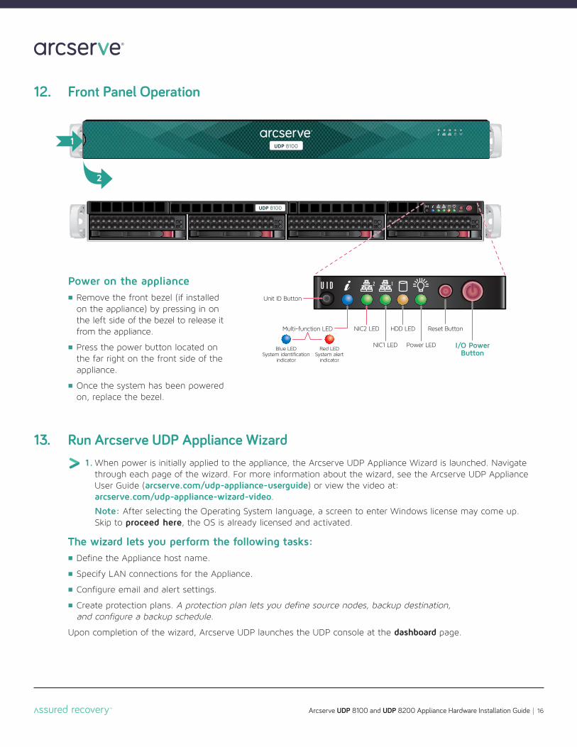
12. Front Panel Operation
HDD LEDNIC2 LED
Power LEDNIC1 LED I/O PowerButton
Reset ButtonMulti-function LED
Blue LEDSystem identification
indicator
Red LEDSystem alert
indicator
Unit ID Button
2
1
Power on the appliancen Remove the front bezel (if installed
on the appliance) by pressing in on the left side of the bezel to release it from the appliance .
n Press the power button located on the far right on the front side of the appliance.
n Once the system has been powered on, replace the bezel.
13. Run Arcserve UDP Appliance Wizard1. When power is initially applied to the appliance, the Arcserve UDP Appliance Wizard is launched. Navigate
through each page of the wizard. For more information about the wizard, see the Arcserve UDP Appliance User Guide (arcserve.com/udp-appliance-userguide) or view the video at:arcserve.com/udp-appliance-wizard-video.
Note: After selecting the Operating System language, a screen to enter Windows license may come up. Skip to proceed here, the OS is already licensed and activated.
The wizard lets you perform the following tasks:n Define the Appliance host name.
n Specify LAN connections for the Appliance.
n Configure email and alert settings.
n Create protection plans. A protection plan lets you define source nodes, backup destination, and configure a backup schedule.
Upon completion of the wizard, Arcserve UDP launches the UDP console at the dashboard page.
Arcserve UDP 8100 and UDP 8200 Appliance Hardware Installation Guide 17
14. Access Arcserve UDPArcserve UDP is a comprehensive solution to protect complex IT environments. The source-side and global deduplication solution protects your data residing in various types of nodes such as Windows, Linux, and virtual machines on VMware ESX servers or Microsoft Hyper-V servers. You can back up data to either a local machine or a recovery point server. A recovery point server is a central server where backups from multiple sources are stored and can be globally deduplicated. For more information about Arcserve UDP, see the Knowledge Center at: arcserve.com/udp-knowledge-center.
Arcserve UDP provides the following capabilities:n Back up the data to deduplication/non-deduplication data stores on recovery point servers
n Back up recovery points to tape
n Create virtual standby machines from backup data
n Replicate backup data to recovery point servers and remote recovery point servers
n Restore backup data and perform Bare Metal Recovery (BMR)
n Copy selected data backup files to a secondary backup location
n Configure and manage Arcserve High Availability (HA) for critical servers in your environment
15. Contact SupportIf you encounter any issues with your appliance, please visit our Arcserve Support site to search our KnowledgeBase for solutions to common problems or to get Live Support for immediate assistance (the serial number is located on rear of appliance) at: arcserve.com/support.
16. WarrantyEach Arcserve UDP 8000 series appliance comes with a 3-year hardware warranty. For detailed informationabout this warranty, please visit: arcserve.com/udp-appliance-warranty.
Arcserve UDP 8100 and UDP 8200 Appliance Hardware Installation Guide 18
Copyright © 2016 Arcserve (USA), LLC and its affiliates and subsidiaries. All rights reserved. All trademarks, trade names, service marks and logos referenced herein belong to their respective owners. This document is for your informational purposes only. Arcserve assumes no responsibility for the accuracy or completeness of the information. To the extent permitted by applicable law, Arcserve provides this document “as is” without warranty of any kind, including, without limitation, any implied warranties of merchantability, fitness for a particular purpose, or non-infringement. In no event will Arcserve be liable for any loss or damage, direct or indirect, from the use of this document, including, without limitation,lost profits, business interruption, goodwill or lost data, even if Arcserve is expressly advised in advance of the possibility of such damage.
For more information on Arcserve, please visit arcserve.com, or call +1.844.639.6792


![VALUE ADDED DISTRIBUTORActive Directory Management [ADM], IT Security [IT SEC] ... Arcserve UDP 8 Arcserve UDP Archiving 9 Arcserve UDP Cloud Direct 10. LUDIS VALUE ADDED DISTRIBUTOR](https://static.documents.pub/doc/80x56/5e79873c64d736507667ff28/value-added-distributor-active-directory-management-adm-it-security-it-sec.jpg)


