23
Arduino
| Date post: | 21-Dec-2015 |
| Category: |
Documents |
| Upload: | gabriel-norman |
| View: | 216 times |
| Download: | 2 times |

Arduino

What is Arduino?

Arduino is a tool for making computers that can sense and control more of the physical world than your desktop computer. It's an open-source physical computing platform based on a simple microcontroller board, and a development environment for writing software for the board.
Arduino can be used to develop interactive objects, taking inputs from a variety of switches or sensors, and controlling a variety of lights, motors, and other physical outputs. Arduino projects can be stand-alone, or they can communicate with software running on your computer (e.g. Flash, Processing, MaxMSP.) The boards can be assembled by hand or purchased preassembled; the open-source IDE can be downloaded for free.

The Arduino programming language is an implementation of Wiring, a similar physical computing platform, which is based on the Processing multimedia programming environment.

DC Motor Control using an
H bridge

To reverse a DC motor, you need to be able to reverse the direction of the current in the motor. The easiest way to do this is using an H-bridge circuit. There are many different models and brands of H-Bridge.

For this lab you'll need:
Solderless Breadboard
22-AWG hookup wire
Arduino microcontroller
Light emitting diodes – LED
10Kohm resistors
SwitchL293NE or SN754410 H-bridge
12V DC power supply
DC motor

Prepare the breadboardConnect power and ground on the breadboard to power and ground from the microcontroller. On the Arduino module, use the 5V and any of the ground connections:

Add a Digital Input (a switch)Connect a switch to digital input 2 on the Arduino.
How your H-bridge worksThe L293NE/SN754410 is a very basic H-bridge. It has two bridges, one on the left side of the chip and one on the right, and can control 2 motors. It can drive up to 1 amp of current, and operate between 4.5V and 36V. The small DC motor you are using in this lab can run safely off a low voltage so this H-bridge will work just fine.

The H-bridge has the following pins and features:• Pin 1 (1,2EN) enables and disables our motor whether
it is give HIGH or LOW• Pin 2 (1A) is a logic pin for our motor (input is either
HIGH or LOW)• Pin 3 (1Y) is for one of the motor terminals• Pin 4-5 are for ground• Pin 6 (2Y) is for the other motor terminal• Pin 7 (2A) is a logic pin for our motor (input is either
HIGH or LOW)• Pin 8 (VCC2) is the power supply for our motor, this
should be given the rated voltage of your motor• Pin 9-11 are unconnected as you are only using one
motor in this lab• Pin 12-13 are for ground• Pin 14-15 are unconnected• Pin 16 (VCC1) is connected to 5V

Below is a diagram of the H-bridge and which pins do what in our example. Included with the diagram is a truth table indicating how the motor will function according to the state of the logic pins (which are set by our Arduino).


Connect the motor to the H-bridgeConnect the motor to the H-bridge as follows:

Or, if you are using an external power supply for the Arduino, you can use the Vin pin.
If you need an external power supply, you can use any DC power supply or battery from 9 – 15V as long as your motor can run at that voltage, and as long as the supply can supply as much current as your motor needs.
Plug an external DC power source into the Arduino’s external power input. You may still leave your USB cable plugged in for quick and easy reprogramming. Whichever motor you use, make sure the power source is compatible (i.e. don’t use a 9V battery for a 3V motor!). The external voltage input is available at the Vin pin, so you can use it both to power the Arduino, and to power the motor.

Note on decoupling capacitors

If you find that your microcontroller is resetting whenever the motor turns on, add a capacitor across power and ground close to the motor. The capacitor will smooth out the voltage dips that occur when the motor turns on. This use of a capacitor is called a decoupling capacitor. Usually a 10 – 100uF capacitor will work. The larger the cap, the more charge it can hold, but the longer it will take to release its charge.
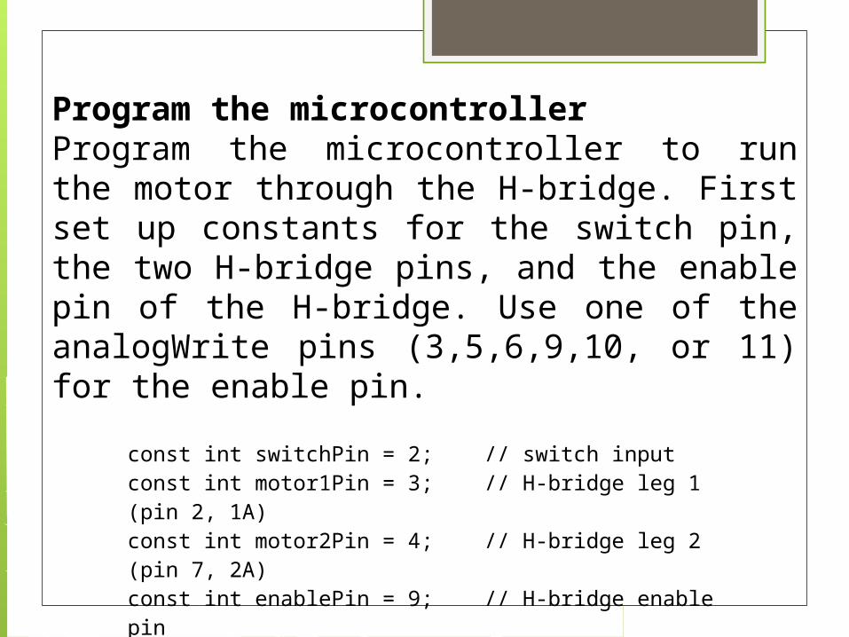
Program the microcontrollerProgram the microcontroller to run the motor through the H-bridge. First set up constants for the switch pin, the two H-bridge pins, and the enable pin of the H-bridge. Use one of the analogWrite pins (3,5,6,9,10, or 11) for the enable pin.
const int switchPin = 2; // switch inputconst int motor1Pin = 3; // H-bridge leg 1 (pin 2, 1A)const int motor2Pin = 4; // H-bridge leg 2 (pin 7, 2A)const int enablePin = 9; // H-bridge enable pin

void setup() { // set the switch as an input: pinMode(switchPin, INPUT); // set all the other pins you're using as outputs: pinMode(motor1Pin, OUTPUT); pinMode(motor2Pin, OUTPUT); pinMode(enablePin, OUTPUT); pinMode(ledPin, OUTPUT); // set enablePin high so that motor can turn on: digitalWrite(enablePin, HIGH); }
In the setup(), set all the pins for the H-bridge as outputs, and the pin for the switch as an input. The set the enable pin high so the H-bridge can turn the motor on.

void loop() { // if the switch is high, motor will turn on one direction: if (digitalRead(switchPin) == HIGH) { digitalWrite(motor1Pin, LOW); // set leg 1 of the H-bridge low digitalWrite(motor2Pin, HIGH); // set leg 2 of the H-bridge high } // if the switch is low, motor will turn in the other direction: else { digitalWrite(motor1Pin, HIGH); // set leg 1 of the H-bridge high digitalWrite(motor2Pin, LOW); // set leg 2 of the H-bridge low } }
In the main loop() read the switch. If it’s high, turn the motor one way by taking one H-bridge pin high and the other low. If the switch is low, reverse the direction by reversing the states of the two H-bridge pins.

Thank You for your attention


