175
ARDUINO PROJECTS BOOK

ARDUINO PROJECTS BOOK

THE ARDUINO PROJECTS BOOK
EDITORSProjects and text by Scott Fitzgerald and Michael Shiloh Additional text review by Tom Igoe
DESIGN AND ART DIRECTIONTODOGiorgio Olivero, Mario Ciardulli, Vanessa Poli, Michelle Nebiolotodo.to.it
DIGITAL FABRICATION AND PROJECT MANAGEMENTOfficine Arduino TorinoKatia De Coi, Enrico Bassi
ADVISORS AND SUPPORTERSMassimo Banzi, Gianluca Martino, Smart Projects
PROJECT TESTERS AND PROOFREADERSMichael Shiloh, Michelle Nebiolo, Katia De Coi, Alessandro Buat, Federico Vanzati, David Mellis
THANKSBig thanks to the entire Arduino user community for their contin-ued contributions, support, and feedback.Special thanks to the Fritzing team: some of the electronic com-ponents illustrations used in the book are taken or modified from the open-source Fritzing project (www.fritzing.org).Heartfelt thanks to Paul Badger for the CapacitiveSensor library used in Project 13.
The text of the Arduino Projects Book is licensed under a Creative Commons Attribution-NonCommercial-ShareAlike 3.0 License 2012 by Arduino LLC. This means that you can copy, reuse, adapt and build upon the text of this book non-commercially while attributing the original work (but not in any way that suggests that we endorse you or your use of the work) and only if the results are transmitted under the same Creative Commons license.Full license terms: creativecommons.org/licenses/by-nc-sa/3.0/
© 2012 Arduino LLC. The Arduino name and logo are trademarks of Arduino, registered in the US and in the rest of the world. Other product and company names mentioned herein are trademarks of their respective companies.
The information in this book is distributed on an “As Is” basis without any further warranties. While every precaution has been taken in the design of this book, neither the authors nor Arduino LLC shall have any liability to any person or entity with respect to any loss or damage caused or declared to be caused directly or indirectly by the instructions contained in this book or by the software and hardware described in it.
This book cannot be sold separately from The Arduino Starter Kit.
Designed, printed and bound in Torino, ItalySeptember 2012

INDEX
00 INTRODUCTION
01 Get to Know Your Tools
02 Spaceship Interface
03 Love-o-Meter
04 Color Mixing Lamp
05 Mood Cue
06 Light Theremin
07 Keyboard Instrument
08 Digital Hourglass
09 Motorized Pinwheel
10 Zoetrope
11 Crystal Ball
12 Knock Lock
13 Touchy-feely Lamp
14 Tweak the Arduino Logo
15 Hacking Buttons
A/Z GLOSSARY
4
20
32
42
52
62
70
78
86
94
102
114
124
136
144
156
162

00
BECOME EXTRAORDINARY
Everyone, every day, uses technology. Most of us leave the
programming to engineers because we think coding and
electronics are complicated and difficult; actually, they can be
fun and exciting activities. Thanks to Arduino, designers, artists,
hobbyists and students of all ages are learning to create things
that light up, move, and respond to people, animals, plants, and
the rest of the world.
Over the years Arduino has been used as the “brain” in thousands
of projects, one more creative than the last. A worldwide
community of makers has gathered around this open-source
platform, moving from personal computing to personal
fabrication, and contributing to a new world of participation,
cooperation and sharing.
Arduino is open and simple. It’s founded on lessons we’ve learned
teaching our own classes: if you start with the assumption that
learning to make digital technologies is simple and accessible,
you can make it so. Suddenly electronics and code become
creative tools that anyone can use – like brushes and paint.
This book walks you through the basics in a hands-on way, with
creative projects you build by learning. Once you’ve mastered
the basics, you’ll have a palette of software and circuits that you
can use to create something beautiful, and make someone smile
with what you invent.
WELCOME TO ARDUINO!ARDUINO MAKES IT AS EASY AS POSSIBLE TO PROGRAM TINY COMPUTERS CALLED MICROCONTROLLERS, WHICH ARE WHAT MAKE OBJECTS INTERACTIVE
You are surrounded by dozens of them every day: they are embedded in timers,
thermostats, toys, remote controls, microwave ovens, even some toothbrushes.
They just do one specific task, and if you hardly notice them – which is often the
case – it’s because they are doing it well. They have been programmed to sense
and control activity using sensors and actuators.
Sensors listen to the physical world. They convert energy that you give off when
you press buttons, or wave your arms, or shout, into electrical signals. Buttons
and knobs are sensors that you touch with your fingers, but there are many other
kinds of sensors.
Actuators take action in the physical world. They convert electrical energy back
into physical energy, like light and heat and movement.
Microcontrollers listen to sensors and talk to actuators. They decide what to
do based on a program that you write.
Microcontrollers and the electronics you attach to them are just the skeleton of
your projects, though. You’ll need to bring skills you probably already have to put
some flesh on the bones.
For example, in one of the projects we suggest, you’ll make an arrow and attach it
to a motor, and put them both in a box with a knob, so you can make a meter to
tell people whether you’re busy or not. In another, you’ll put some lights and a tilt
switch on a cardboard frame to make an hourglass.
Arduino can make your projects responsive, but only you can make them beautiful. We’ll provide some suggestions along the way as to how you might
do that.
Arduino was designed to help you get things done. To make that happen, we kept
the background material on programming and electronics to a minimum. If you
decide you want to know more about these aspects, there are lots of good guides
available. We’ll provide a couple of references, and you can find more online at:
arduino.cc/starterkit

Arduino Uno - The microcontroller develop-
ment board that will be at the heart of your
projects. It’s a simple computer, but one that
has no way for you to interact with it yet. You
will be building the circuits and interfaces for
interaction, and telling the microcontroller how
to interface with other components.
+-
+-
+-
+-
Battery Snap - Used to connect a 9V battery to
power leads that can be easily plugged into a
breadboard or your Arduino.
Breadboard - A board on which you can build
electronic circuits. It’s like a patch panel, with
rows of holes that allow you to connect wires
and components together. Versions that re-
quire soldering are available, as well as the sol-
der-less type used here.
Capacitors - These components store and re-
lease electrical energy in a circuit. When the
circuit’s voltage is higher than what is stored in
the capacitor, it allows current to flow in, giv-
ing the capacitor a charge. When the circuit’s
voltage is lower, the stored charge is released.
Often placed across power and ground close to
a sensor or motor to help smooth fluctuations
in voltage.
DC motor - Converts electrical energy into me-
chanical energy when electricity is applied to
its leads. Coils of wire inside the motor become
magnetized when current flows through them.
+PARTS INYOUR KIT
6Welcome to Arduino!Introduction
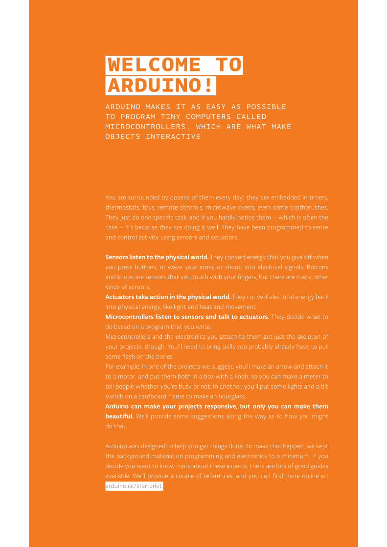
These magnetic fields attract and repel mag-
nets, causing the shaft to spin. If the direction
of the electricity is reversed, the motor will spin
in the opposite direction.
Diode - Ensures electricity only flows in one di-
rection. Useful when you have a motor or other
high current/voltage load in your circuit. Di-
odes are polarized, meaning that the direction
that they’re placed in a circuit matters. Placed
one way, they allow current to pass through.
Placed the other way, they block it. The anode
side generally connects to the point of higher
energy in your circuit. The cathode typically
connects to the point of lower energy, or to
ground. The cathode is usually marked with a
band on one side of the component’s body.
Gels (red, green, blue) - These filter out differ-
ent wavelengths of light. When used in con-
junction with photoresistors, they cause the
sensor to only react to the amount of light in
the filtered color.
H-bridge - A circuit that allows you to control
the polarity of the voltage applied to a load,
usually a motor. The H-bridge in the kit is an in-
tegrated circuit, but it could also be construct-
ed with a number of discrete components.
Jumper wires - Use these to connect compo-
nents to each other on the breadboard, and to
the Arduino.
Light Emitting Diodes (LEDs) - A type of diode
that illuminates when electricity passes through
it. Like all diodes, electricity only flows in one
direction through these components. You’re
probably familiar with these as indicators on a
variety of electronic devices. The anode, which
typically connects to power, is usually the long-
er leg, and the cathode is the shorter leg.
Liquid Crystal Display (LCD) - A type of alpha-
numeric or graphic display based on liquid crys-
tals. LCDs are available in a many sizes, shapes,
and styles. Yours has 2 rows with 16 characters
each.
- +
- +
7
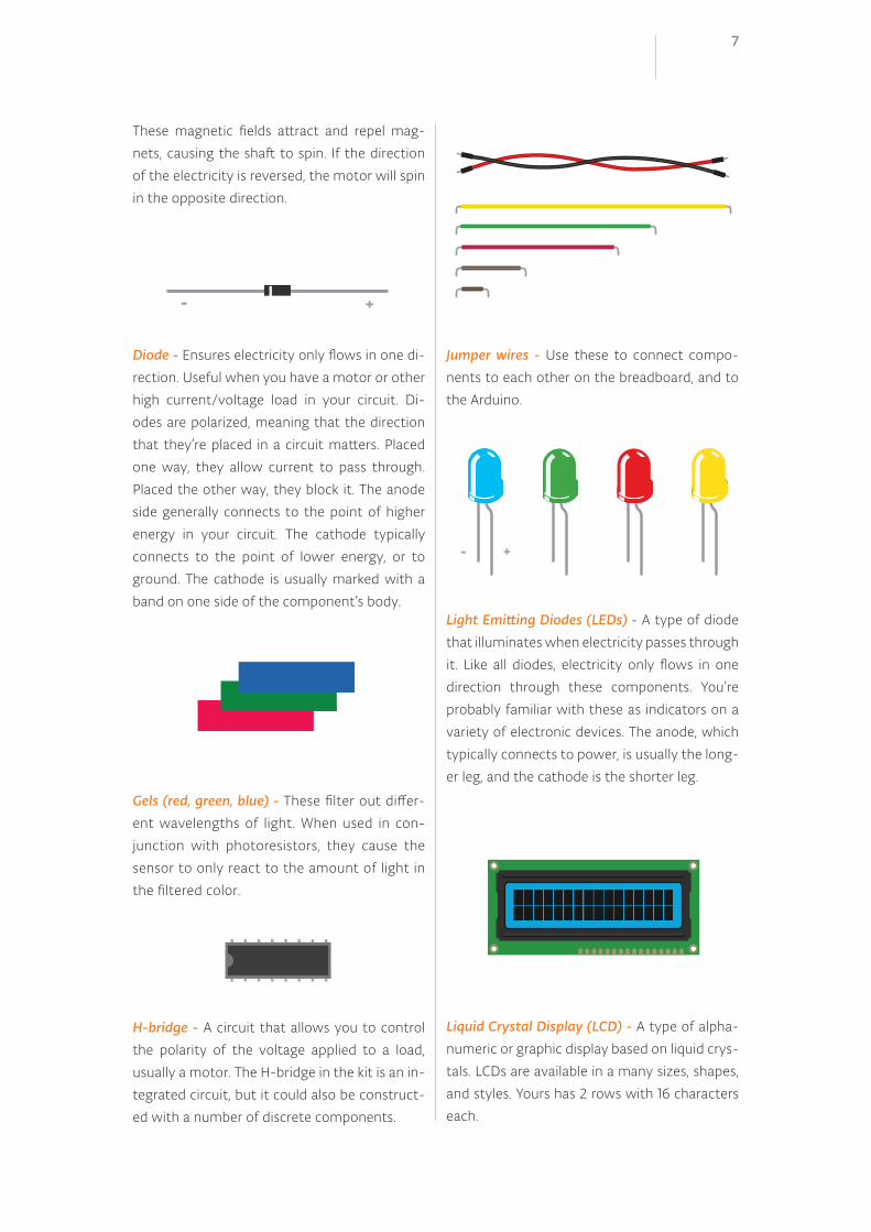
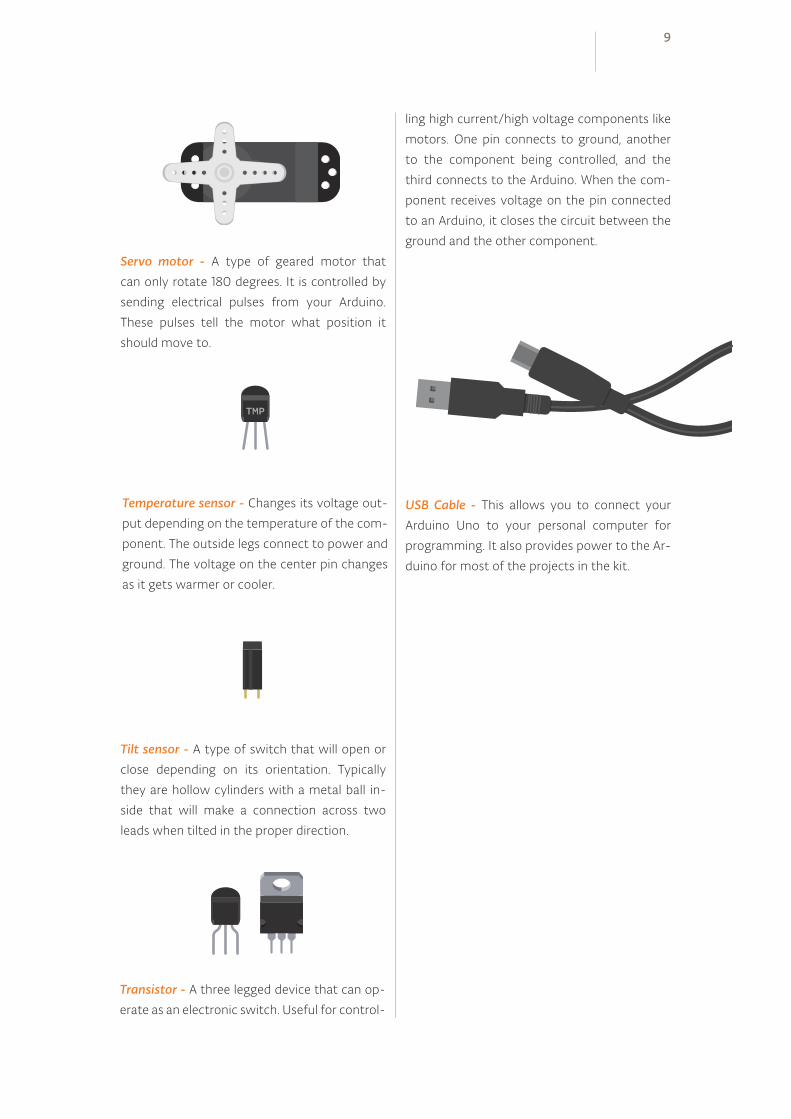
Resistors - Resist the flow of electrical energy
in a circuit, changing the voltage and current
as a result. Resistor values are measured in
ohms (represented by the Greek omega char-
acter: Ω). The colored stripes on the sides of
resistors indicate their value (see resistor color
code table).
Optocoupler - This allows you to connect two
circuits that do not share a common power
supply. Internally there is a small LED that,
when illuminated, causes a photoreceptor in-
side to close an internal switch. When you ap-
ply voltage to the + pin, the LED lights and the
internal switch closes. The two outputs replace
a switch in the second circuit.
Piezo - An electrical component that can be
used to detect vibrations and create noises.
Photoresistor - (also called a photocell, or light-
dependent resistor). A variable resistor that
changes its resistance based on the amount of
light that falls on its face.
Potentiometer - A variable resistor with three
pins. Two of the pins are connected to the ends
of a fixed resistor. The middle pin, or wiper,
moves across the resistor, dividing it into two
halves. When the external sides of the poten-
tiometer are connected to voltage and ground,
the middle leg will give the difference in voltage
as you turn the knob. Often referred to as a pot.
Pushbuttons - Momentary switches that close
a circuit when pressed. They snap into bread-
boards easily. These are good for detecting on/
off signals.
Male header pins - These pins fit into female
sockets, like those on a breadboard. They help
make connecting things much easier.
8Welcome to Arduino!Introduction
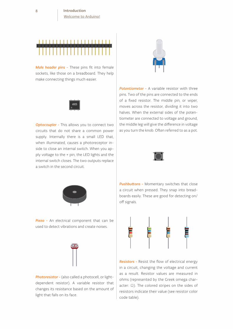
USB Cable - This allows you to connect your
Arduino Uno to your personal computer for
programming. It also provides power to the Ar-
duino for most of the projects in the kit.
Temperature sensor - Changes its voltage out-
put depending on the temperature of the com-
ponent. The outside legs connect to power and
ground. The voltage on the center pin changes
as it gets warmer or cooler.
Tilt sensor - A type of switch that will open or
close depending on its orientation. Typically
they are hollow cylinders with a metal ball in-
side that will make a connection across two
leads when tilted in the proper direction.
Transistor - A three legged device that can op-
erate as an electronic switch. Useful for control-
ling high current/high voltage components like
motors. One pin connects to ground, another
to the component being controlled, and the
third connects to the Arduino. When the com-
ponent receives voltage on the pin connected
to an Arduino, it closes the circuit between the
ground and the other component.
Servo motor - A type of geared motor that
can only rotate 180 degrees. It is controlled by
sending electrical pulses from your Arduino.
These pulses tell the motor what position it
should move to.
9
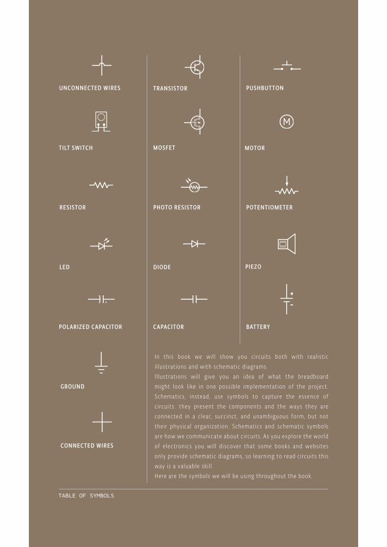
TABLE OF SYMBOLS
UNCONNECTED WIRES
LED DIODE
PUSHBUT TON
PIEZO
TILT SWITCH
POL ARIZED CAPACITOR
MOSFET
TRANSISTOR
CAPACITOR
MOTOR
BAT TERY
RESISTOR
GROUND
PHOTO RESISTOR POTENTIOMETER
In th is book we wi l l show you c i rcu its both with rea l ist ic i l lustrat ions and with schematic d iagrams. I l lustrat ions wi l l g ive you an idea of what the breadboard might look l ike in one poss ib le implementat ion of the project . Schematics , instead , use symbols to capture the essence of c i rcu its : they present the components and the ways they are connected in a c lear , succ inct , and unambiguous form, but not thei r phys ica l organizat ion . Schematics and schematic symbols are how we communicate about c i rcu its . As you explore the wor ld of e lectronics you wi l l d iscover that some books and websites only provide schematic d iagrams, so learn ing to read c i rcu its th is way is a va luable sk i l l .Here are the symbols we wi l l be us ing throughout the book.
CONNECTED WIRES

THE BOARD
11
USB portUsed for powering your Arduino Uno, uploading your sketches to your Arduino, and for communicat ing with your Arduino sketch (via Ser ia l .pr int ln() etc .)
ATmega microcontrollerThe heart of your Arduino Uno.
Power connectorThis is how you power your Arduino when it's not plugged into a USB port for power. Can accept voltages between 7-12V.
Reset ButtonResets the ATmega microcontrol ler .
TX and RX LEDsThese LEDs indicate communi-cation between your Arduino and your computer. Expect them to f l icker rapidly dur ing sketch upload as wel l as dur ing ser ia l communicat ion. Useful for debugging.
Pin 13 LEDThe only actuator bui lt- it to your Arduino Uno. Besides being a handy target for your f i rst b l ink sketch, this LED is very useful for debugging.
Power LEDIndicates that your Arudino is receiv ing power. Useful for debugging.
Analog inUse these pins with analogRead() .
GND and 5V pinsUse these pins to provide +5V power and ground to your c i rcuits .
Digital pinsUse these pins with digita l-Read() , d ig ita lWrite() , and analogWrite() . analogWrite() works only on the pins with the PWM symbol .
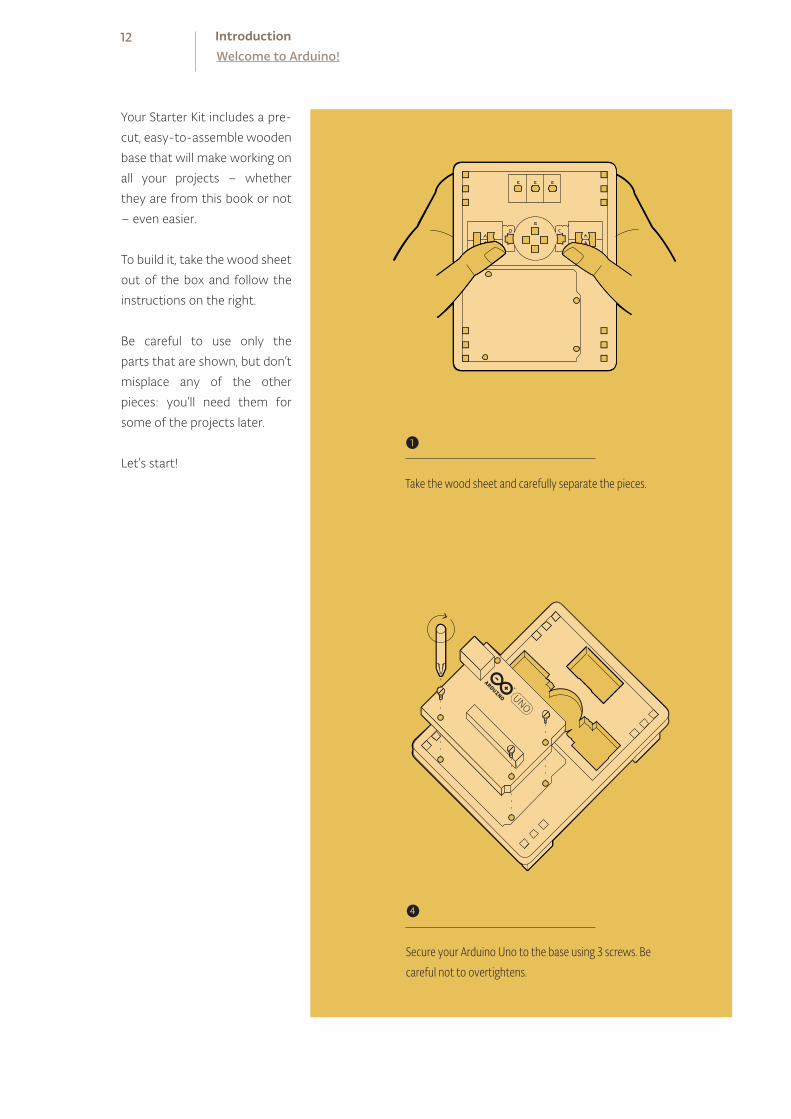
Your Starter Kit includes a pre-
cut, easy-to-assemble wooden
base that will make working on
all your projects – whether
they are from this book or not
– even easier.
To build it, take the wood sheet
out of the box and follow the
instructions on the right.
Be careful to use only the
parts that are shown, but don’t
misplace any of the other
pieces: you’ll need them for
some of the projects later.
Let’s start!❶
Take the wood sheet and carefully separate the pieces.
❹
Secure your Arduino Uno to the base using 3 screws. Be careful not to overtightens.
12Welcome to Arduino!Introduction
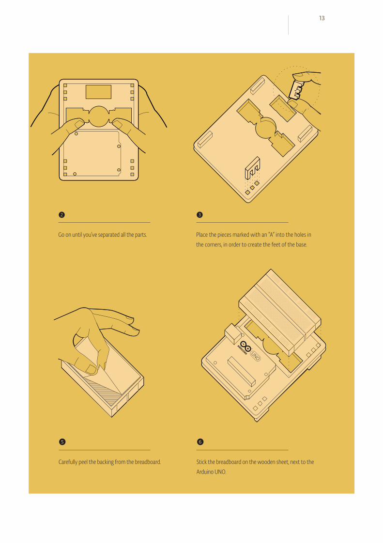
❷
Go on until you’ve separated all the parts.
❸
Place the pieces marked with an “A” into the holes in the corners, in order to create the feet of the base.
❺
Carefully peel the backing from the breadboard.
❻
Stick the breadboard on the wooden sheet, next to the Arduino UNO.
13
9V battery
Small light source like aflashlight
Conductive material likealuminum foil or copper mesh
Colored paper
Scissors
An old CD or DVD
Tape and glue
THINGS YOUNEED TOSUPPLY
-
A box that you can makeholes into
Basic tools like a screwdriver
9V battery powered componentAny battery powered electronic device with at
least one switch or pushbutton that you’re will-
ing to hack into will do the job.
Soldering iron and solder(necessary only in Project 15)
14Welcome to Arduino!Introduction
WELCOME TO ARDUINO! BEFORE YOU START CONTROLLING THE WORLD AROUND YOU, YOU’LL NEED TO DOWNLOAD THE IDE TO PROGRAM YOUR BOARD
The Arduino IDE allows you to write programs and upload them
to your Arduino.
Download the latest version of the IDE from:
arduino.cc/download
Have your Arduino board and USB cable near your computer. Don’t plug them in just yet.
Follow the appropriate procedures in the next pages for Windows,
Mac OS X or Linux.
The online version of this guide is available at:
arduino.cc/guide
SETTING UP
When the download of the IDE finishes, unzip the downloaded
file. Make sure to preserve the folder structure. Double-click the
folder to open it. There should be a few files and sub-folders
inside.
Connect the Arduino to your computer with the USB cable. Your
Arduino will automatically draw power from either the USB con-
nection to the computer or an external power supply.
The green power light (labeled PWR) should turn on.
Windows should initiate its driver installation process when the
board is plugged in. Your computer won’t be able to find the driv-
ers by itself, so you’ll need to tell it where they are located.
In the Device Manager, you should now see a port listing similar
to “Arduino UNO (COM4)”.
Congratulations! You've installed the Arduino IDE on your computer.
— Click on the Start Menu and open the Control Panel.
— Navigate to “System and Security”. Open the Device Manager.
— In Windows XP, look for the listing named "Ports (COM & LPT)"
and right click on the "USB device" port; in Vista and Windows 7,
right click on "Unknown device" under "Other devices".
— Choose "Update Driver Software".
— On Windows XP and Windows 7, you will be asked whether
to install automatically or "with a path". Chose the second option,
"with a path". On Windows Vista proceed directly to the next step.
— Select the “Browse my computer for Driver software” option.
— Navigate to the folder you unzipped in the earlier step.
Locate and select the “Drivers” folder in the main Arduino folder
(not the “FTDI USB Drivers” sub-directory). Press “OK” and “Next”
to proceed.
— If you are prompted with a warning dialog about not passing
Windows Logo testing, click “Continue Anyway”.
— Windows now will take over the driver installation.
WINDOWSINSTALLATION
Onl ine vers ionarduino.cc/windows
❶
❷
❸
INSTRUCTION FOR:
WINDOWS 7, VISTA,
AND XP
16 IntroductionSetting Up

When the download of the IDE finished, double-click the .zip fle.
This will expand the Arduino application.
Copy the Arduino application into the Applications folder, or
wherever else you wish to install the software.
Connect the board to the computer with the USB cable. The
green power LED (labeled PWR) should turn on.
You do not need to install any drivers to work with the board.
Depending on the version of OS X that you are running, you
might get a dialog box asking if you wish to open the “Network
Preferences”. Click the “Network Preferences...” button, and then
click “Apply”.
The Uno will show up as “Not Configured”, but it is still working.
You can quit the System Preferences.
Congratulations! You have Arduino all set up and you're ready to start making projects.
MAC OS XINSTALLATION
Onl ine vers ionarduino.cc/mac
❶
❷
❸
❹
❺
INSTRUCTION FOR:
OS X 10.5 AND
LATER
If you’re using Linux, please visit the website for instructions:
arduino.cc/linuxLINUXINSTALLATION
17

Fig. 1
COMMUNICATING WITH THE ARDUINO
Now that you’ve installed the Arduino IDE and made sure your computer can talk to the board, it’s time to make sure you can up-load a program.
Double-click the Arduino application to open it. If the IDE loads
in the wrong language, you can change this in the application
preferences. Look for “Language Support” on this page for de-
tails: arduino.cc/ide
Navigate to the LED blink example sketch ('sketch' is what Ar-
duino programs are called). It's located under:
FILE > EXAMPLES > 01.BASICS > BLINK
A window with some text in it should have opened. Leave the
window be for now, and select your board under:
TOOLS > BOARD menu
18 IntroductionSetting Up
Choose the serial port your Arduino is connected to from the
TOOLS > SERIAL PORT menu.
— On Windows. This is likely to be the COM with the highest
number. There is no harm in guessing wrong, and if it doesn’t
work, try the next one. To find out, you can disconnect your
Arduino board and re-open the menu; the entry that disappears
should be the Arduino board. Reconnect the board and select
that serial port.
— On Mac. This should be something with /dev/tty.usbmodem
in it. There are usually two of these; select either one.
To upload the Blink sketch to your Arduino, press the UPLOAD
toggle in the top left corner of the window. See Fig. 1.
❶
❷
❸
❹
❺

Fig. 2
ADDITIONALINFORMATION
19
You should see a bar indicating the progress of the upload near the
lower left corner of the Arduino IDE, and the lights labeled TX and
RX on the Arduino board will be blinking. If the upload is successful,
the IDE will display the message DONE UPLOADING.
A few seconds after the upload has completed, you should see the
yellow LED with an L next to it start blinking. See Fig. 2.
If this is the case, congratulations! You’ve successfully pro-grammed the Arduino to blink its onboard LED!
Sometimes your brand new Arduino is already programmed with
the Blink sketch, so you can’t tell if you are truly in control. If this is
the case, change the delay time by changing the number in the
parenthesis to 100, and upload the Blink sketch again. Now the
LED should blink much faster.
Congratulations! You really are in control! Now it’s time to move on to Project 1. (You needn’t save any changes you have made.)
If you have problems with any of the steps outlined above, please
see the troubleshooting suggestions:
arduino.cc/trouble
While you’re getting ready to build your projects, you can look at
the following page for additional information about the Arduino’s
programming environment:
arduino.cc/ide
You might also want to look at:
— the examples for using various sensors and actuators
arduino.cc/tutorial
— the reference for the Arduino language
arduino.cc/examples
❻
❼

SWITCH
LED
220 OHM RESISTOR
INGREDIENTS
01

YOU’LL MAKE A SIMPLE CIRCUIT WITH SOMESWITCHES, AN LED, AND A RESISTOR
Electricity is a type of energy, much like heat, gravity, or light. Electrical energy flows through conductors, like wire. You can convert electrical energy into other forms of energy to do something interesting, like turn on a light or make some noise out of a speaker.
The components you might use to do this, like speakers or light bulbs, are electri-
cal transducers. Transducers change other types of energy into electrical energy
and vice versa. Things that convert other forms of energy into electrical energy are
often called sensors, and things that convert electrical energy into other forms
of energy are sometimes called actuators. You will be building circuits to move
electricity through different components. Circuits are closed loops of wire with
a power source (like a battery) and something to do something useful with the
energy, called a load.
In a circuit, electricity flows from a point of higher potential energy (usually re-
ferred to as power or +) to a point of lower potential energy. Ground (often repre-
sented with a - or GND) is generally the point of least potential energy in a circuit.
In the circuits you are building, electricity only flows in one direction. This type of
circuit is called direct current, or DC. In alternating current (AC) circuits electricity
changes its direction 50 or 60 times a second (depending on where you live). This
is the type of electricity that comes from a wall socket.
There are a few terms you should be familiar with when working with electri-
cal circuits. Current (measured in amperes, or amps; with the A symbol) is the
amount of electrical charge flowing past a specific point in your circuit. Voltage
(measured in volts; with the V symbol) is the difference in energy between one
point in a circuit and another. And finally, resistance (measured in ohms; with the
Ω symbol) is how much a component resists the flow of electrical energy.
GET TO KNOW YOUR TOOLS
Time: 30 MINUTESLevel:
Discover: basic electrical theory, how a breadboard works, components in series and parallel
21
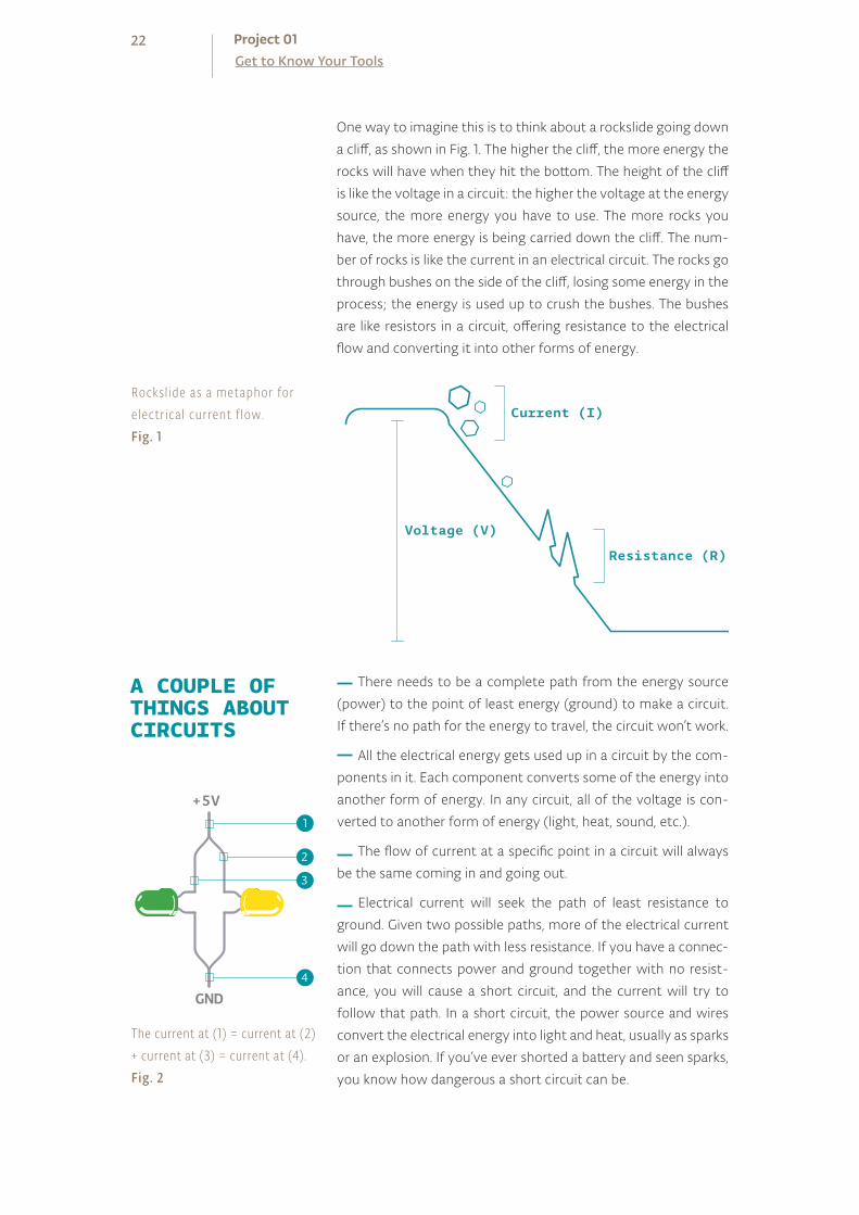
One way to imagine this is to think about a rockslide going down
a cliff, as shown in Fig. 1. The higher the cliff, the more energy the
rocks will have when they hit the bottom. The height of the cliff
is like the voltage in a circuit: the higher the voltage at the energy
source, the more energy you have to use. The more rocks you
have, the more energy is being carried down the cliff. The num-
ber of rocks is like the current in an electrical circuit. The rocks go
through bushes on the side of the cliff, losing some energy in the
process; the energy is used up to crush the bushes. The bushes
are like resistors in a circuit, offering resistance to the electrical
flow and converting it into other forms of energy.
There needs to be a complete path from the energy source
(power) to the point of least energy (ground) to make a circuit.
If there’s no path for the energy to travel, the circuit won’t work.
All the electrical energy gets used up in a circuit by the com-
ponents in it. Each component converts some of the energy into
another form of energy. In any circuit, all of the voltage is con-
verted to another form of energy (light, heat, sound, etc.).
The flow of current at a specific point in a circuit will always
be the same coming in and going out.
Electrical current will seek the path of least resistance to
ground. Given two possible paths, more of the electrical current
will go down the path with less resistance. If you have a connec-
tion that connects power and ground together with no resist-
ance, you will cause a short circuit, and the current will try to
follow that path. In a short circuit, the power source and wires
convert the electrical energy into light and heat, usually as sparks
or an explosion. If you’ve ever shorted a battery and seen sparks,
you know how dangerous a short circuit can be.
Voltage (V)
Resistance (R)
Current (I)
22Get to Know Your ToolsProject 01
A COUPLE OFTHINGS ABOUTCIRCUITS
Rocksl ide as a metaphor for e lectr ical current f low.Fig. 1
The current at (1) = current at (2) + current at (3) = current at (4).Fig. 2
5V
1
+5V
GND
2
1
4
3
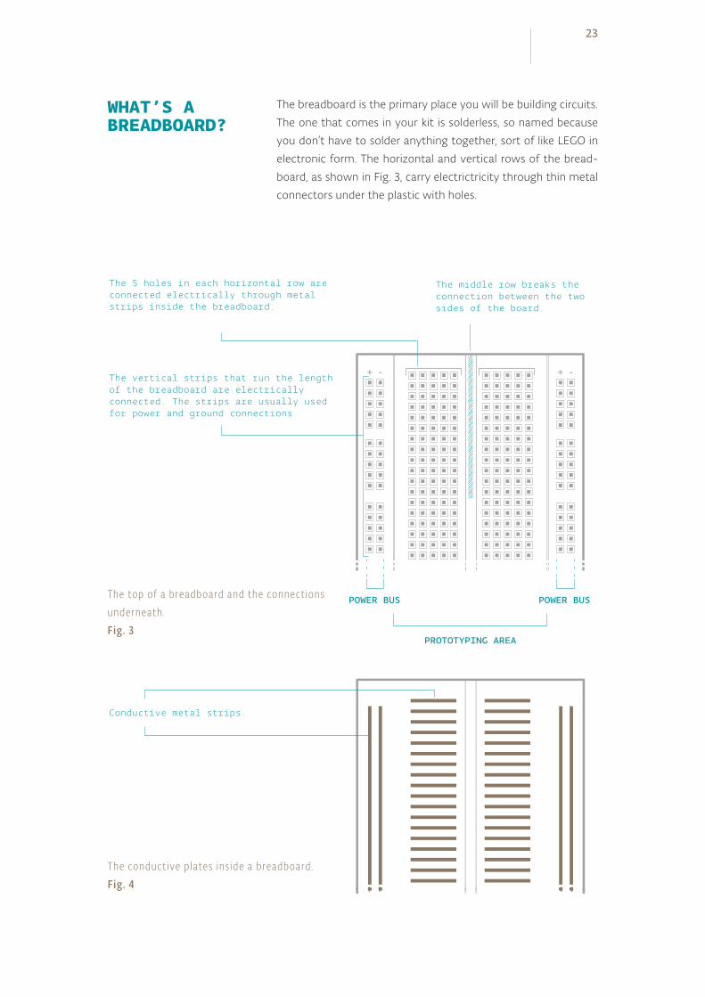
The breadboard is the primary place you will be building circuits.
The one that comes in your kit is solderless, so named because
you don’t have to solder anything together, sort of like LEGO in
electronic form. The horizontal and vertical rows of the bread-
board, as shown in Fig. 3, carry electrictricity through thin metal
connectors under the plastic with holes.
+ -+ -
The 5 holes in each horizontal row are connected electrically through metal strips inside the breadboard.
The middle row breaks the connection between the two sides of the board.
The vertical strips that run the length of the breadboard are electrically connected. The strips are usually used for power and ground connections.
Conductive metal strips.
POWER BUS POWER BUS
PROTOTYPING AREA
23
WHAT’S ABREADBOARD?
The top of a breadboard and the connect ions underneath.Fig. 3
The conductive plates ins ide a breadboard.Fig. 4

24Get to Know Your ToolsProject 01
Throughout these projects, you’ll see two views of circuits: one in
breadboard view (like in Fig. 5), that looks like the stuff in your kit.
The other is a schematic view (like in Fig. 6), which is a more abstract
way of showing the relationships between components in a circuit.
Schematics don’t always show where components are placed rela-
tive to each other, but they show how they are connected.
+ - + -
+ -+ -
CIRCUITDRAWINGS
Circuit i l lustrat ion.Fig. 5
Schematic v iewFig. 6
An LED, or light-emitting diode, is a component that converts electrical energy
into light energy. LEDs are polarized components, which means they only allow
electricity to flow through them in one direction. The longer leg on the LED is
called an anode, it will connect to power. The shorter leg is a cathode and will con-
nect to ground. When voltage is applied to the anode of the LED, and the cathode
is connected to ground, the LED emits light.
A resistor is a component that resists the flow of electrical energy (see the com-
ponents list for an explanation on the colored stripes on the side). It converts
some of the electrical energy into heat. If you put a resistor in series with a com-
ponent like an LED, the resistor will use up some of the electrical energy and the
LED will receive less energy as a result. This allows you to supply components
with the amount of energy they need. You use a resistor in series with the LED to
keep it from receiving too much voltage. Without the resistor, the LED would be
brighter for a few moments, but quickly burn out.
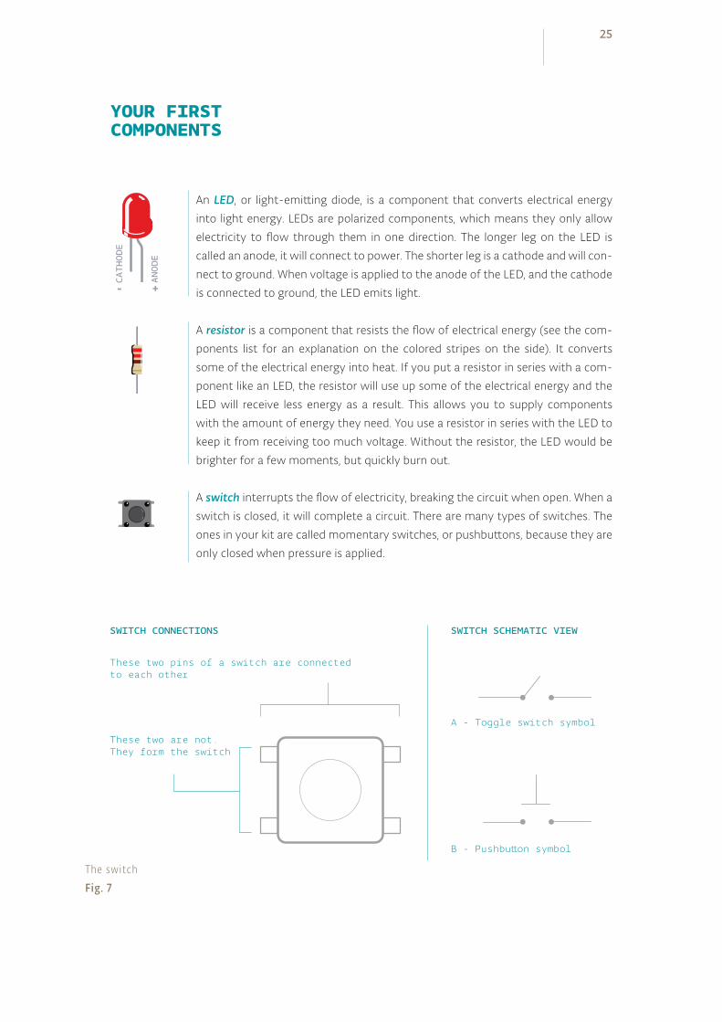
A switch interrupts the flow of electricity, breaking the circuit when open. When a
switch is closed, it will complete a circuit. There are many types of switches. The
ones in your kit are called momentary switches, or pushbuttons, because they are
only closed when pressure is applied.
25
YOUR FIRSTCOMPONENTS
The switchFig. 7
-
CATHODE
These two pins of a switch are connectedto each other
These two are not.They form the switch
SWITCH SCHEMATIC VIEW
A - Toggle switch symbol
SWITCH CONNECTIONS
B - Pushbutton symbol
+
ANODE

26Get to Know Your ToolsProject 01
Fig. 8
BUILD THECIRCUIT
+ - + -
+ -+ -
Fig. 9
Your first interactive circuit, using a switch, a resistor and an LED. Arduino is just the power source for this circuit; in later projects, you'll connect its input and output pins to control more complex circuits.
27
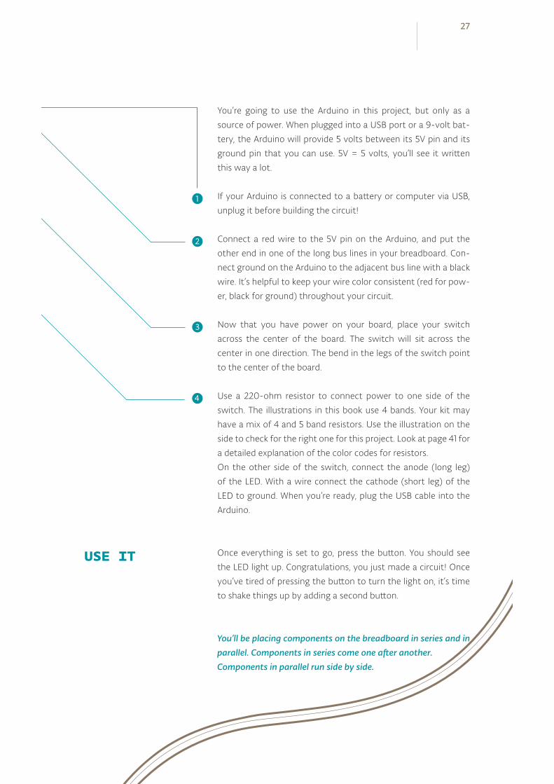
You’re going to use the Arduino in this project, but only as a
source of power. When plugged into a USB port or a 9-volt bat-
tery, the Arduino will provide 5 volts between its 5V pin and its
ground pin that you can use. 5V = 5 volts, you’ll see it written
this way a lot.
If your Arduino is connected to a battery or computer via USB,
unplug it before building the circuit!
Connect a red wire to the 5V pin on the Arduino, and put the
other end in one of the long bus lines in your breadboard. Con-
nect ground on the Arduino to the adjacent bus line with a black
wire. It’s helpful to keep your wire color consistent (red for pow-
er, black for ground) throughout your circuit.
Now that you have power on your board, place your switch
across the center of the board. The switch will sit across the
center in one direction. The bend in the legs of the switch point
to the center of the board.
Use a 220-ohm resistor to connect power to one side of the
switch. The illustrations in this book use 4 bands. Your kit may
have a mix of 4 and 5 band resistors. Use the illustration on the
side to check for the right one for this project. Look at page 41 for
a detailed explanation of the color codes for resistors.
On the other side of the switch, connect the anode (long leg)
of the LED. With a wire connect the cathode (short leg) of the
LED to ground. When you’re ready, plug the USB cable into the
Arduino.
Once everything is set to go, press the button. You should see
the LED light up. Congratulations, you just made a circuit! Once
you’ve tired of pressing the button to turn the light on, it’s time
to shake things up by adding a second button.
USE IT
You’ll be placing components on the breadboard in series and in parallel. Components in series come one after another. Components in parallel run side by side.
❶
❷
❸
❹
28Get to Know Your ToolsProject 01
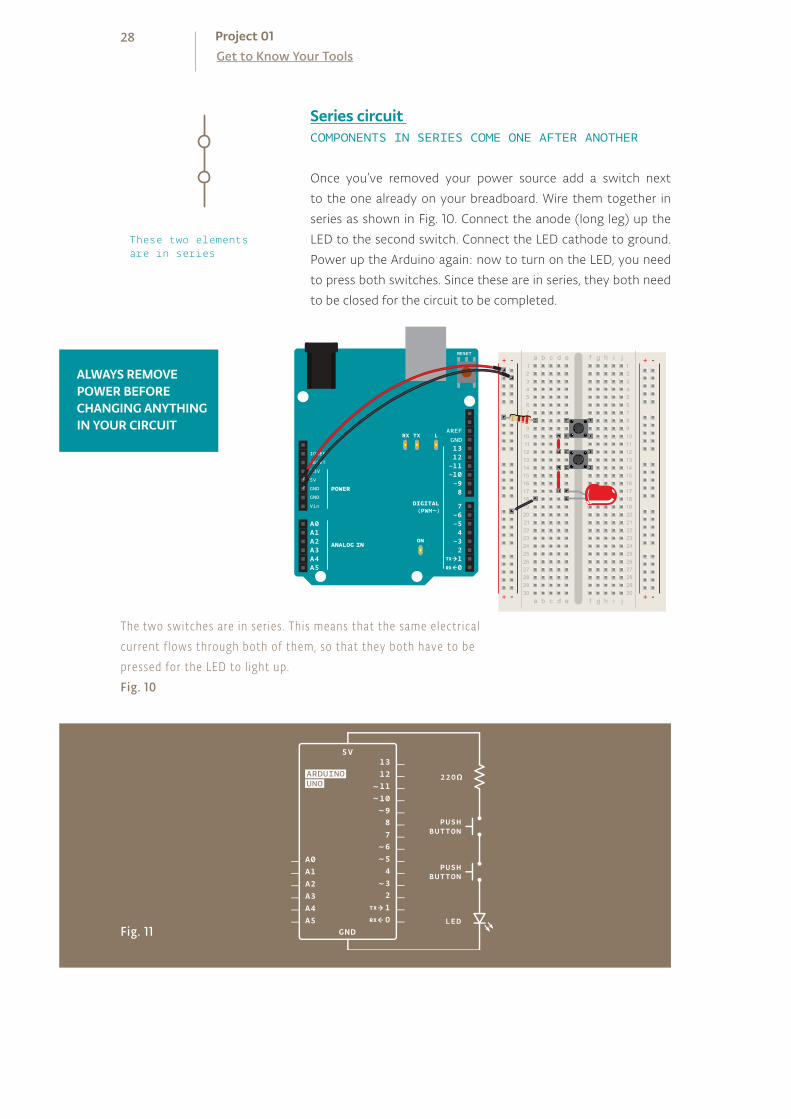
Once you’ve removed your power source add a switch next
to the one already on your breadboard. Wire them together in
series as shown in Fig. 10. Connect the anode (long leg) up the
LED to the second switch. Connect the LED cathode to ground.
Power up the Arduino again: now to turn on the LED, you need
to press both switches. Since these are in series, they both need
to be closed for the circuit to be completed.
Series circuit COMPONENTS IN SERIES COME ONE AFTER ANOTHER
+ - + -
+ -+ -
ALWAYS REMOVE POWER BEFORE CHANGING ANYTHING IN YOUR CIRCUIT
The two switches are in ser ies . This means that the same electr ical current f lows through both of them, so that they both have to be pressed for the LED to l ight up.Fig. 10
Fig. 11
These two elements are in series
29
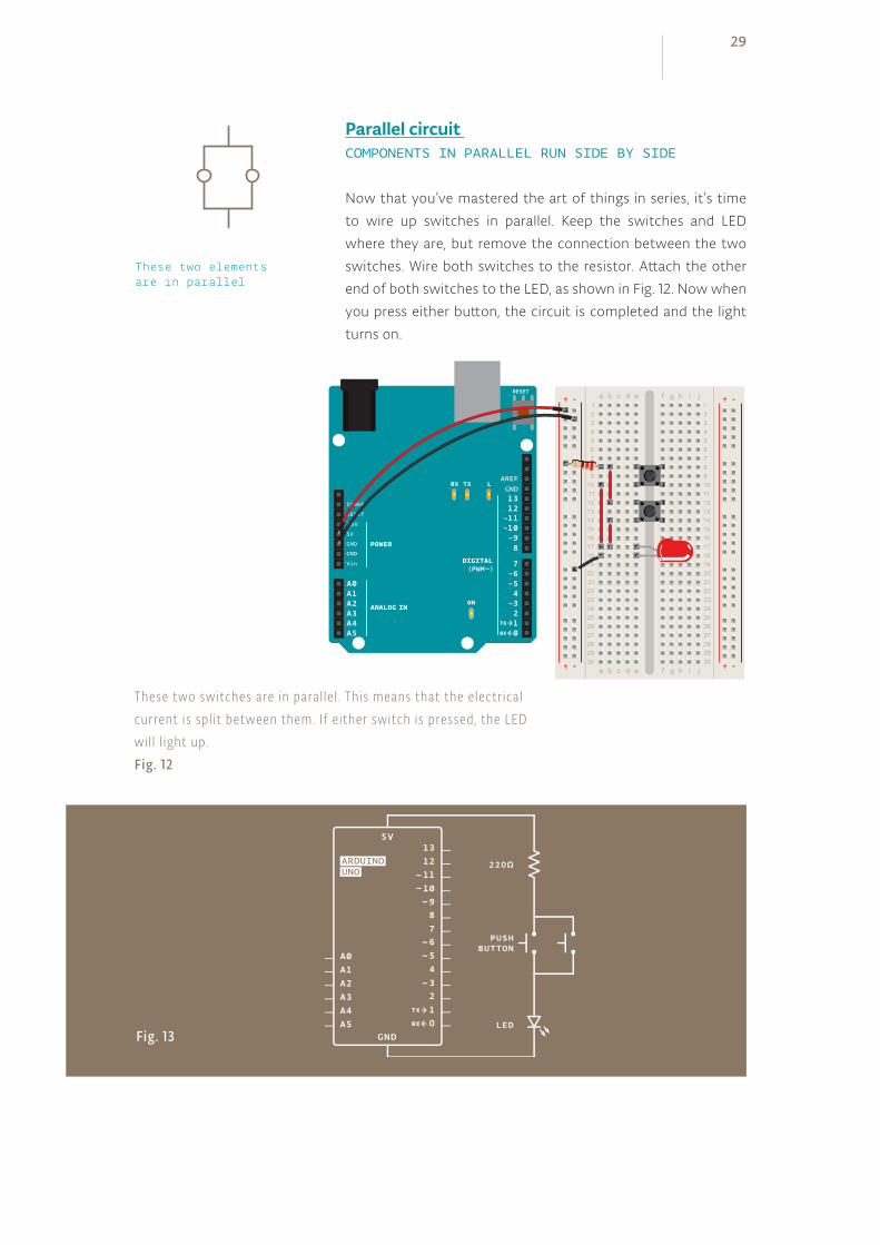
Now that you’ve mastered the art of things in series, it’s time
to wire up switches in parallel. Keep the switches and LED
where they are, but remove the connection between the two
switches. Wire both switches to the resistor. Attach the other
end of both switches to the LED, as shown in Fig. 12. Now when
you press either button, the circuit is completed and the light
turns on.
+ - + -
+ -+ -
Parallel circuit COMPONENTS IN PARALLEL RUN SIDE BY SIDE
These two switches are in paral le l . This means that the e lectr ical current is spl i t between them. I f e ither switch is pressed, the LED wi l l l ight up.Fig. 12
Fig. 13
These two elements are in parallel
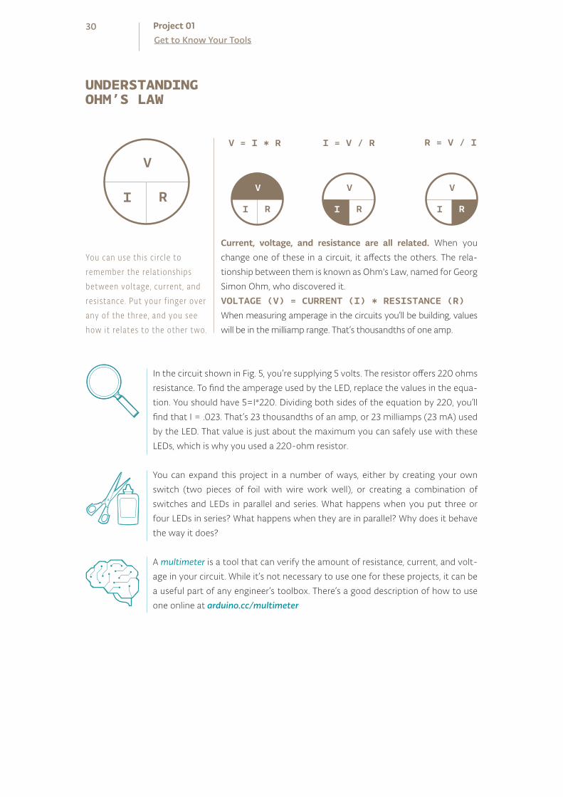
V
I R
You can use this c i rc le to remember the re lat ionships between voltage, current , and res istance. Put your f inger over any of the three , and you see how it re lates to the other two.
Current, voltage, and resistance are all related. When you
change one of these in a circuit, it affects the others. The rela-
tionship between them is known as Ohm's Law, named for Georg
Simon Ohm, who discovered it.
VOLTAGE (V) = CURRENT (I) * RESISTANCE (R)When measuring amperage in the circuits you’ll be building, values
will be in the milliamp range. That’s thousandths of one amp.
V
I R
V
I R
I = V / R R = V / I
V
I R
V = I * R
In the circuit shown in Fig. 5, you’re supplying 5 volts. The resistor offers 220 ohms
resistance. To find the amperage used by the LED, replace the values in the equa-
tion. You should have 5=I*220. Dividing both sides of the equation by 220, you’ll
find that I = .023. That’s 23 thousandths of an amp, or 23 milliamps (23 mA) used
by the LED. That value is just about the maximum you can safely use with these
LEDs, which is why you used a 220-ohm resistor.
You can expand this project in a number of ways, either by creating your own
switch (two pieces of foil with wire work well), or creating a combination of
switches and LEDs in parallel and series. What happens when you put three or
four LEDs in series? What happens when they are in parallel? Why does it behave
the way it does?
A multimeter is a tool that can verify the amount of resistance, current, and volt-
age in your circuit. While it’s not necessary to use one for these projects, it can be
a useful part of any engineer’s toolbox. There’s a good description of how to use
one online at arduino.cc/multimeter
30Get to Know Your ToolsProject 01
UNDERSTANDINGOHM’S LAW
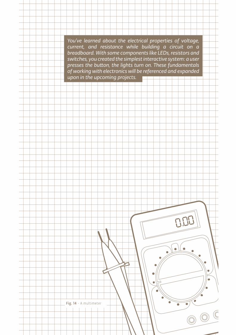
Fig. 14 - A mult imeter
You’ve learned about the electrical properties of voltage, current, and resistance while building a circuit on a breadboard. With some components like LEDs, resistors and switches, you created the simplest interactive system: a user presses the button, the lights turn on. These fundamentals of working with electronics will be referenced and expanded upon in the upcoming projects.

10 KILOHM RESISTOR
SWITCH
220 OHM RESISTOR
LED
INGREDIENTS
02
Time: 45 MINUTESLevel:
YOUR ARDUINO IS GOING TO STAR IN A SCIENCE FICTION MOVIE
Now that you’ve got the basics of electricity under control, it’s time to move onto controlling things with your Arduino. In this project, you’ll be building something that could have been a spaceship interface in a 1970s science fiction movie. You’ll make a cool control panel with a switch and lights that turn on when you press the switch. You can decide whether the lights mean “Engage Hyperdrive” or “Fire the lasers!”. A green LED will be on, until you press a button. When the Arduino gets a signal from the button, the green light will turn off and 2 other lights will start blinking.
The Arduino’s digital pins can read only two states: when there is voltage on an
input pin, and when there’s not. This kind of input is normally called digital (or
sometimes binary, for two-states). These states are commonly referred to as
HIGH and LOW. HIGH is the same as saying “there’s voltage here!” and LOW means
“there’s no voltage on this pin!”. When you turn an OUTPUT pin HIGH using a
command called digitalWrite(), you’re turning it on. Measure the voltage
between the pin and ground, you’ll get 5 volts. When you turn an OUTPUT pin
LOW, you’re turning it off.
The Arduino’s digital pins can act as both inputs and outputs. In your code, you’ll
configure them depending on what you want their function to be. When the pins
are outputs, you can turn on components like LEDs. If you configure the pins as
inputs, you can check if a switch is being pressed or not. Since pins 0 and 1 are used
for communicating with the computer, it’s best to start with pin 2.
SPACESHIP INTERFACE
Builds on project: 1
Discover: digital input and output, your first program, variables
33

+ - + -
+ -+ -
BUILD THECIRCUIT
Fig. 1
Fig. 2
34Spaceship InterfaceProject 02

Wire up your breadboard to the Arduino’s 5V and ground
connections, just like the previous project. Place the two red
LEDs and one green LED on the breadboard. Attach the cathode
(short leg) of each LED to ground through a 220-ohm resistor.
Connect the anode (long leg) of the green LED to pin 3. Connect
the red LEDs’ anodes to pins 4 and 5, respectively.
Place the switch on the breadboard just as you did in the previous
project. Attach one side to power, and the other side to digital
pin 2 on the Arduino. You’ll also need to add a 10k-ohm resistor
from ground to the switch pin that connects to the Arduino.
That pull-down resistor connects the pin to ground when the
switch is open, so it reads LOW when there is no voltage coming
in through the switch.
❶
❷
❶
Fold the pre-cut paper as shown.
❷
Place the folded paper over the breadboard. The three LEDs and pushbutton will help keep it in place.
35
You can cover the breadboard the template provided in the kit. Or you can deco-
rate it to make your own launch system. The lights turning on and off mean noth-
ing by themselves, but when you put them in a control panel and give them labels,
they gain meaning. What do you want the green LED to mean? What do the flash-
ing red LEDs mean? You decide!

Every Arduino program has two main functions. Functions are
parts of a computer program that run specific commands. Func-
tions have unique names, and are “called” when needed. The
necessary functions in an Arduino program are called setup()
and loop(). These functions need to be declared, which means
that you need to tell the Arduino what these functions will do.
setup() and loop() are declared as you see on the right.
In this program, you’re going to create a variable before you get
into the main part of the program. Variables are names you give
to places in the Arduino’s memory so you can keep track of what
is happening. These values can change depending on your pro-
gram’s instructions.
Variable names should be descriptive of whatever value they are
storing. For example, a variable named switchState tells you
what it stores: the state of a switch. On the other hand, a vari-
able named “x” doesn’t tell you much about what it stores.
To create a variable, you need to declare what type it is. The
data type int will hold a whole number (also called an integer); that’s any number without a decimal point. When you declare a
variable, you usually give it an initial value as well. The declaration
of the variable as every statement must end with a semicolon (;).
The setup() runs once, when the Arduino is first powered on.
This is where you configure the digital pins to be either inputs
or outputs using a function named pinMode(). The pins
connected to LEDs will be OUTPUTs and the switch pin will be
an INPUT.
The loop() runs continuously after the setup() has
completed. The loop() is where you’ll check for voltage on the
inputs, and turn outputs on and off. To check the voltage level
on a digital input, you use the function digitalRead() that
checks the chosen pin for voltage. To know what pin to check,
digitalRead() expects an argument. Arguments are information that you pass to functions,
telling them how they should do their job. For example,
digitalRead() needs one argument: what pin to check. In
your program, digitalRead() is going to check the state of
Create the loop funct ion
Configure pin funct ional ity
Let ’s start coding
THE CODE
Some notes before you start
36Spaceship InterfaceProject 02

Case sensitivity Pay attention to the case sensitivity in your code. For example, pinMode is the name of a command, but pinmode will produce an error.
1
2
3
4
5
6
7
8
9
10
void setup()
void loop()
int switchState = 0;
void setup()
pinMode(3,OUTPUT);
pinMode(4,OUTPUT);
pinMode(5,OUTPUT);
pinMode(2,INPUT);
void loop()
switchState = digitalRead(2);
// this is a comment
CommentsIf you ever want to include natural language in your program, you can leave a comment. Comments are notes you leave for yourself that the computer ignores. To write a comment, add two slashes // The computer will ignore anything on the line after those slashes.
Curly brackets Any code you write inside the curly brackets will be executed when the function is called.
37
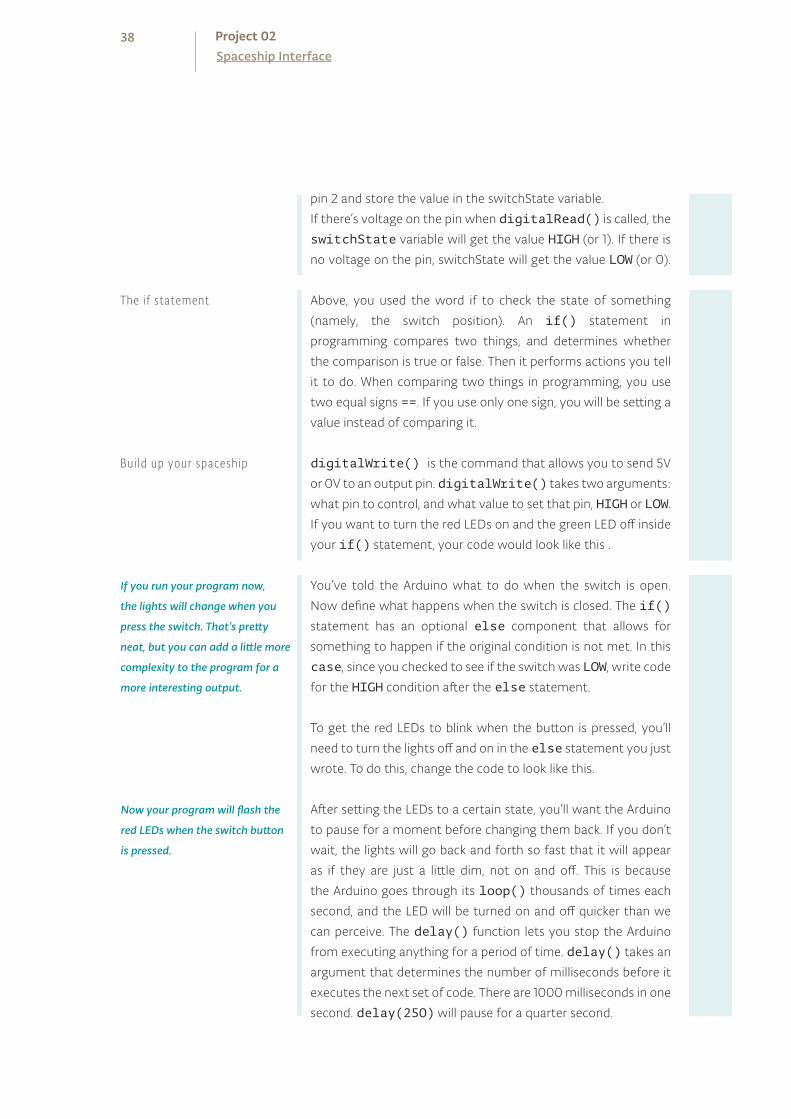
pin 2 and store the value in the switchState variable.
If there’s voltage on the pin when digitalRead() is called, the
switchState variable will get the value HIGH (or 1). If there is
no voltage on the pin, switchState will get the value LOW (or 0).
Above, you used the word if to check the state of something
(namely, the switch position). An if() statement in
programming compares two things, and determines whether
the comparison is true or false. Then it performs actions you tell
it to do. When comparing two things in programming, you use
two equal signs ==. If you use only one sign, you will be setting a
value instead of comparing it.
digitalWrite() is the command that allows you to send 5V
or 0V to an output pin. digitalWrite() takes two arguments:
what pin to control, and what value to set that pin, HIGH or LOW.
If you want to turn the red LEDs on and the green LED off inside
your if() statement, your code would look like this .
You’ve told the Arduino what to do when the switch is open.
Now define what happens when the switch is closed. The if()
statement has an optional else component that allows for
something to happen if the original condition is not met. In this
case, since you checked to see if the switch was LOW, write code
for the HIGH condition after the else statement.
To get the red LEDs to blink when the button is pressed, you’ll
need to turn the lights off and on in the else statement you just
wrote. To do this, change the code to look like this.
After setting the LEDs to a certain state, you’ll want the Arduino
to pause for a moment before changing them back. If you don’t
wait, the lights will go back and forth so fast that it will appear
as if they are just a little dim, not on and off. This is because
the Arduino goes through its loop() thousands of times each
second, and the LED will be turned on and off quicker than we
can perceive. The delay() function lets you stop the Arduino
from executing anything for a period of time. delay() takes an
argument that determines the number of milliseconds before it
executes the next set of code. There are 1000 milliseconds in one
second. delay(250) will pause for a quarter second.
If you run your program now,
the lights will change when you
press the switch. That’s pretty
neat, but you can add a little more
complexity to the program for a
more interesting output.
Now your program will flash the
red LEDs when the switch button
is pressed.
38Spaceship InterfaceProject 02
Bui ld up your spaceship
The i f statement

if (switchState == LOW)
// the button is not pressed
digitalWrite(3, HIGH); // green LED
digitalWrite(4, LOW); // red LED
digitalWrite(5, LOW); // red LED
else // the button is pressed
digitalWrite(3, LOW);
digitalWrite(4, LOW);
digitalWrite(5, HIGH);
delay(250); // wait for a quarter second
// toggle the LEDs
digitalWrite(4, HIGH);
digitalWrite(5, LOW);
delay(250); // wait for a quarter second
// go back to the beginning of the loop
11
12
13
14
15
16
17
18
19
20
It can be helpful to write out the flow of your program in pseudocode: a way of describing what you want the program to do in plain language, but structured in a way that makes it easy to write a real program from it. In this case you’re going to determine if switchState is HIGH (meaning the button is pressed) or not. If the switch is pressed, you’ll turn the green LED off and the red ones on. In pseudocode, the statement could look like this:
if the switchState is LOW: turn the green LED on turn the red LEDs off
if the switchState is HIGH: turn the green LED off turn the red LEDs on
21
22
23
24
25
26
27
39

In this project, you created your first Arduino program to control the behavior of some LEDs based on a switch. You’ve used variables, an if()...else statement, and functions to read the state of an input and control outputs.
When you start creating an interface for your project, think about what people’s
expectations are while using it. When they press a button, will they want immedi-
ate feedback? Should there be a delay between their action and what the Arduino
does? Try and place yourself in the shoes of a different user while you design, and
see if your expectations match up to the reality of your project.
40Spaceship InterfaceProject 02
How would you get the red LEDs to be blinking when your program starts?
How could you make a larger, or more complex interface for your interstellar ad-
ventures with LEDs and switches?
Once your Arduino is programmed, you should see the green
light turn on. When you press the switch, the red lights will start
flashing, and the green light will turn off. Try changing the time of
the two delay() functions; notice what happens to the lights
and how the response of the system changes depending on the
speed of the flashing. When you call a delay() in your program,
it stops all other functionality. No sensor readings will happen until
that time period has passed. While delays are often useful, when
designing your own projects make sure they are not unnecessarily
interfering with your interface.
USE IT
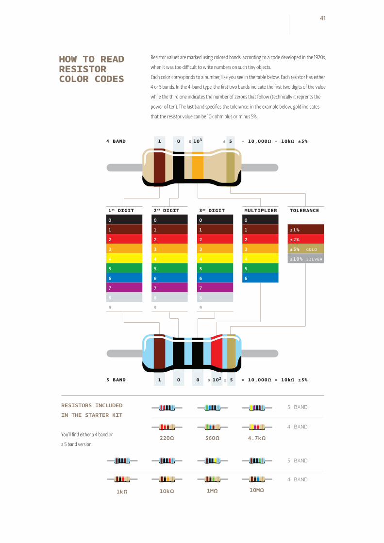
220Ω 560Ω 4.7kΩ
5 BANDRESISTORS INCLUDED
IN THE STARTER KIT
You’ll find either a 4 band or
a 5 band version.
4 BAND
5 BAND
4 BAND
1kΩ 10kΩ 1MΩ 10MΩ
5 BAND
4 BAND
1st DIGIT
0
1
2
3
4
5
6
7
8
9
2nd DIGIT
0
1
2
3
4
5
6
7
8
9
3rd DIGIT
0
1
2
3
4
5
6
7
8
9
MULTIPLIER
0
1
2
3
4
5
6
TOLERANCE
±1%
±2%
±5% GOLD
±10% SILVER
1 = 10,000Ω = 10kΩ ±5% 0 x ±103 5
1 = 10,000Ω = 10kΩ ±5% 0 0 x ±102 5
41
HOW TO READ RESISTOR COLOR CODES
Resistor values are marked using colored bands, according to a code developed in the 1920s,
when it was too difficult to write numbers on such tiny objects.
Each color corresponds to a number, like you see in the table below. Each resistor has either
4 or 5 bands. In the 4-band type, the first two bands indicate the first two digits of the value
while the third one indicates the number of zeroes that follow (technically it reprents the
power of ten). The last band specifies the tolerance: in the example below, gold indicates
that the resistor value can be 10k ohm plus or minus 5%.

TEMPERATURE SENSOR
220 OHM RESISTOR
LED
INGREDIENTS
03
TURN THE ARDUINO INTO A LOVE MACHINE. USING AN ANALOG INPUT, YOU’RE GOING TO REGISTER JUST HOW HOT YOU REALLY ARE!
While switches and buttons are great, there’s a lot more to the physical world than on and off. Even though the Arduino is a digital tool, it’s possible for it to get infor-mation from analog sensors to measure things like temperature or light. To do this, you’ll take advantage of the Arduino’s built-in Analog-to-Digital Converter (ADC). Analog in pins A0-A5 can report back a value between 0-1023, which maps to a range from 0 volts to 5 volts.
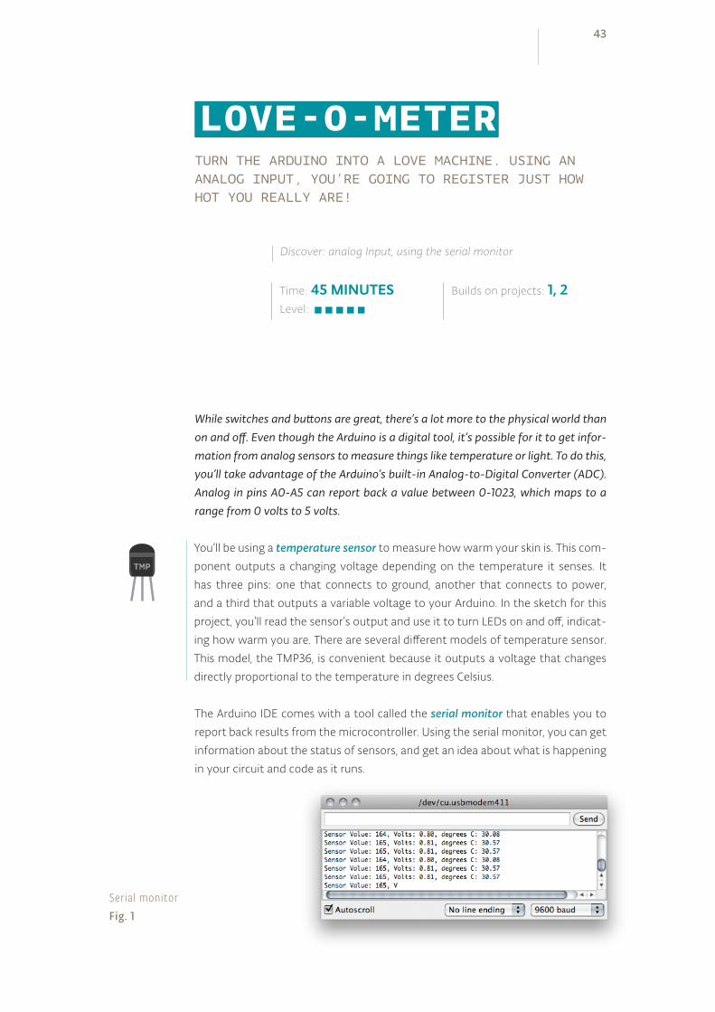
The Arduino IDE comes with a tool called the serial monitor that enables you to
report back results from the microcontroller. Using the serial monitor, you can get
information about the status of sensors, and get an idea about what is happening
in your circuit and code as it runs.
Time: 45 MINUTESLevel:
Builds on projects: 1, 2
Discover: analog Input, using the serial monitor
LOVE-O-METER
You’ll be using a temperature sensor to measure how warm your skin is. This com-
ponent outputs a changing voltage depending on the temperature it senses. It
has three pins: one that connects to ground, another that connects to power,
and a third that outputs a variable voltage to your Arduino. In the sketch for this
project, you’ll read the sensor’s output and use it to turn LEDs on and off, indicat-
ing how warm you are. There are several different models of temperature sensor.
This model, the TMP36, is convenient because it outputs a voltage that changes
directly proportional to the temperature in degrees Celsius.
Ser ia l monitorFig. 1
43
+ - + -
+ -+ -
BUILD THECIRCUIT
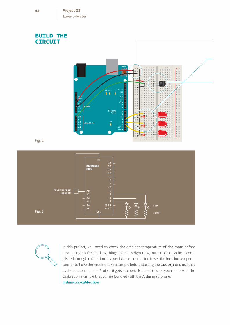
Fig. 2
Fig. 3
In this project, you need to check the ambient temperature of the room before
proceeding. You’re checking things manually right now, but this can also be accom-
plished through calibration. It’s possible to use a button to set the baseline tempera-
ture, or to have the Arduino take a sample before starting the loop() and use that
as the reference point. Project 6 gets into details about this, or you can look at the
Calibration example that comes bundled with the Arduino software:
arduino.cc/calibration
44Love-o-MeterProject 03
Just as you’ve been doing in the earlier projects, wire up your
breadboard so you have power and ground.
Attach the cathode (short leg) of each of the LEDs you’re using to
ground through a 220-ohm resistor. Connect the anodes of the
LEDs to pins 2 through 4. These will be the indicators for the project.
Place the TMP36 on the breadboard with the rounded part fac-
ing away from the Arduino (the order of the pins is important!)
as shown in Fig. 2. Connect the left pin of the flat facing side to
power, and the right pin to ground. Connect the center pin to pin
A0 on your Arduino. This is analog input pin 0.
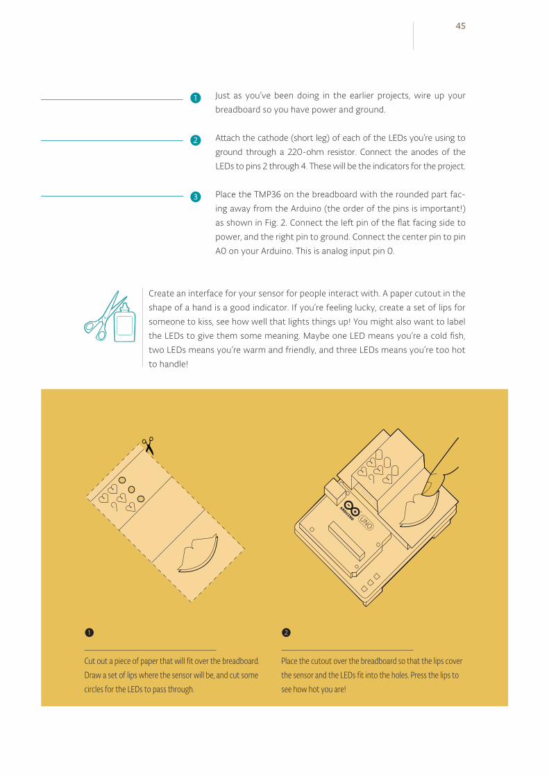
Create an interface for your sensor for people interact with. A paper cutout in the
shape of a hand is a good indicator. If you’re feeling lucky, create a set of lips for
someone to kiss, see how well that lights things up! You might also want to label
the LEDs to give them some meaning. Maybe one LED means you’re a cold fish,
two LEDs means you’re warm and friendly, and three LEDs means you’re too hot
to handle!
❶
❷
❸
❶
Cut out a piece of paper that will fit over the breadboard. Draw a set of lips where the sensor will be, and cut some circles for the LEDs to pass through.
❷
Place the cutout over the breadboard so that the lips cover the sensor and the LEDs fit into the holes. Press the lips to see how hot you are!
45

Constants are similar to variables in that they allow you to
uniquely name things in the program, but unlike variables they
cannot change. Name the analog input for easy reference, and
create another named constant to hold the baseline temperature.
For every 2 degrees above this baseline, an LED will turn on.
You’ve already seen the int datatype, used here to identify which
pin the sensor is on. The temperature is being stored as a float, or
floating-point number. This type of number has a decimal point,
and is used for numbers that can be expressed as fractions.
In the setup you’re going to use a new command, Serial.
begin(). This opens up a connection between the Arduino and
the computer, so you can see the values from the analog input
on your computer screen.
The argument 9600 is the speed at which the Arduino will
communicate, 9600 bits per second. You will use the Arduino
IDE’s serial monitor to view the information you choose to
send from your microcontroller. When you open the IDE’s serial
monitor verify that the baud rate is 9600.
Next up is a for() loop to set some pins as outputs. These are
the pins that you attached LEDs to earlier. Instead of giving them
unique names and typing out the pinMode() function for each
one, you can use a for() loop to go through them all quickly.
This is a handy trick if you have a large number of similar things
you wish to iterate through in a program. Tell the for() loop to
run through pins 2 to 4 sequentially.
In the loop(), you’ll use a local variable named sensorVal
to store the reading from your sensor. To get the value from
the sensor, you call analogRead() that takes one argument:
what pin it should take a voltage reading on. The value, which is
between 0 and 1023, is a representation of the voltage on the pin.
The function Serial.print() sends information from the
Arduino to a connected computer. You can see this information
in your serial monitor. If you give Serial.print() an
argument in quotation marks, it will print out the text you typed.
If you give it a variable as an argument, it will print out the value
of that variable.
THE CODE
A pair of useful constants
Init ia l ize the ser ia l port to the desired speed
Initialize the digital pin directions and turn off
Read the temperature sensor
Send the temperature sensor values to the computer
46Love-o-MeterProject 03
1
2
3
4
5
6
7
8
9
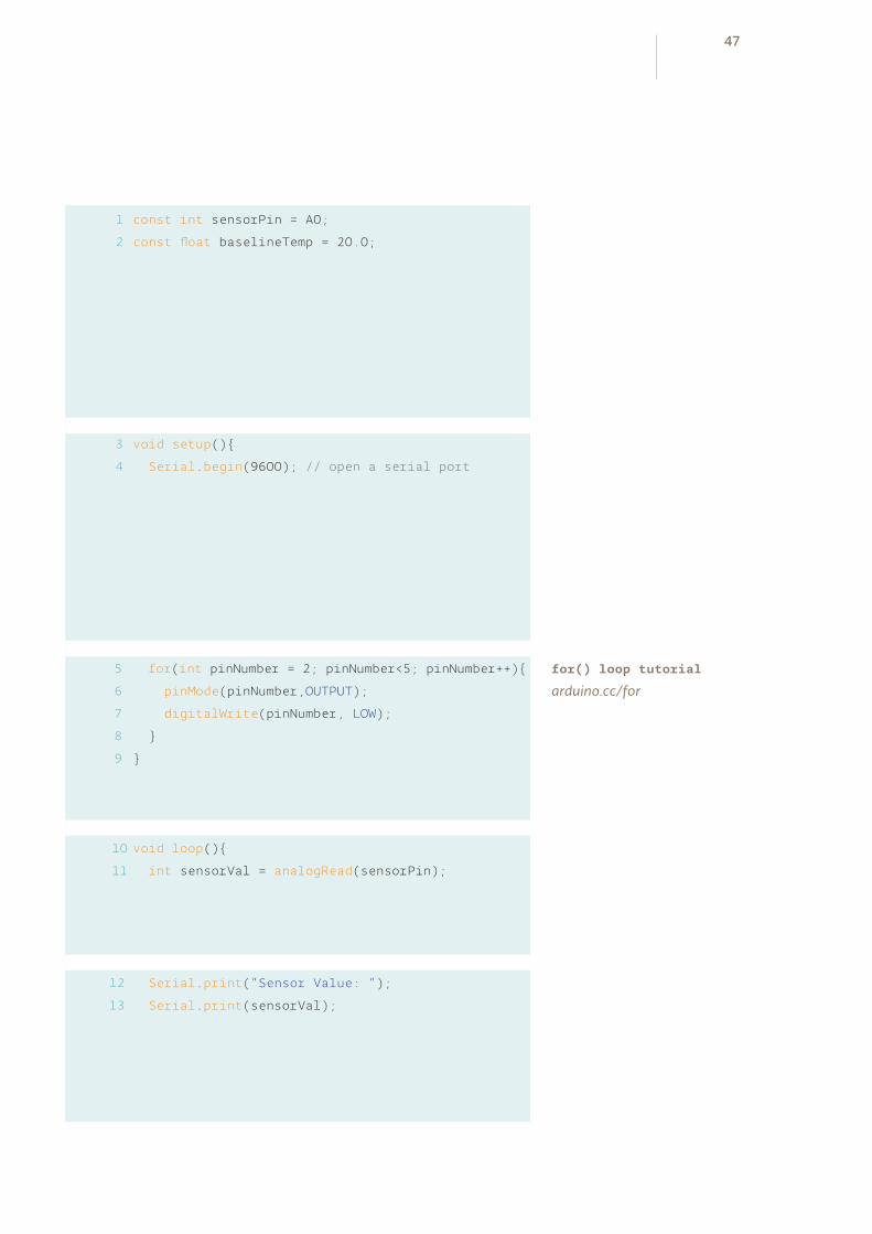
const int sensorPin = A0;
const float baselineTemp = 20.0;
void setup()
Serial.begin(9600); // open a serial port
for(int pinNumber = 2; pinNumber<5; pinNumber++)
pinMode(pinNumber,OUTPUT);
digitalWrite(pinNumber, LOW);
void loop()
int sensorVal = analogRead(sensorPin);
Serial.print(“Sensor Value: “);
Serial.print(sensorVal);
10
11
12
13
for() loop tutorial
arduino.cc/for
47

With a little math, it’s possible to figure out what the real voltage
on the pin is. The voltage will be a value between 0 and 5 volts,
and it will have a fractional part (for example, it might be 2.5
volts), so you’ll need to store it inside a float. Create a variable
named voltage to hold this number. Divide sensorVal by
1024.0 and multiply by 5.0. The new number represents the
voltage on the pin.
Just like with the sensor value, you’ll print this out to the serial
monitor.
If you examine the sensor’s datasheet, there is information about
the range of the output voltage. Datasheets are like manuals
for electronic components. They are written by engineers, for
other engineers. The datasheet for this sensor explains that
every 10 millivolts of change from the sensor is equivalent to
a temperature change of 1 degree Celsius. It also indicates that
the sensor can read temperatures below 0 degrees. Because of
this, you’ll need to create an offset for values below freezing (0
degrees). If you take the voltage, subtract 0.5, and multiply by
100, you get the accurate temperature in degrees Celsius. Store
this new number in a floating point variable called temperature.
Now that you have the real temperature, print that out to the
serial monitor too. Since the temperature variable is the last
thing you’re going to be printing out in this loop, you’re going
to use a slightly different command: Serial.println(). This
command will create a new line in the serial monitor after it
sends the value. This helps make things easier to read in when
they are being printed out.
With the real temperature, you can set up an if()...else
statement to light the LEDs. Using the baseline temperature as
a starting point, you’ll turn on one LED on for every 2 degrees
of temperature increase above that baseline. You’re going
to be looking for a range of values as you move through the
temperature scale.
Convert the voltage to temperature and send the value to the computer
Convert sensor reading to voltage
Turn off LEDs for a low temperature
48Love-o-MeterProject 03

// convert the ADC reading to voltage
float voltage = (sensorVal/1024.0) * 5.0;
Serial.print(“, Volts: “);
Serial.print(voltage);
Serial.print(“, degrees C: “);
// convert the voltage to temperature in degrees
float temperature = (voltage - .5) * 100;
Serial.println(temperature);
if(temperature < baselineTemp)
digitalWrite(2, LOW);
digitalWrite(3, LOW);
digitalWrite(4, LOW);
14
15
16
17
18
19
20
21
22
23
24
25
Starter Kit datasheets
arduino.cc/kitdatasheets
49

The && operator means “and”, in a logical sense. You can check
for multiple conditions: “if the temperature is 2 degrees greater
than the baseline, and it is less than 4 degrees above the baseline.”
If the temperature is between two and four degrees above the
baseline, this block of code turns on the LED on pin 3 as well.
The Analog-to-Digital Converter can only read so fast, so you
should put a small delay at the very end of your loop(). If you
read from it too frequently, your values will appear erratic.
With the code uploaded to the Arduino, click the serial monitor
icon. You should see a stream of values coming out, formatted
like this : Sensor: 200, Volts: .70, degrees C: 17
Try putting your fingers around the sensor while it is plugged into
the breadboard and see what happens to the values in the serial
monitor. Make a note of what the temperature is when the sen-
sor is left in the open air.
Close the serial monitor and change the baselineTemp constant
in your program to the value you observed the temperature to
be. Upload your code again, and try holding the sensor in your
fingers. As the temperature rises, you should see the LEDs turn
on one by one. Congratulations, hot stuff!
USE IT
Turn on one LED for a low temperature
Turn on two LEDs for a medium temperature
Turn on three LEDs for a high temperature
50Love-o-MeterProject 03

else if(temperature >= baselineTemp+2 &&
temperature < baselineTemp+4)
digitalWrite(2, HIGH);
digitalWrite(3, LOW);
digitalWrite(4, LOW);
else if(temperature >= baselineTemp+4 &&
temperature < baselineTemp+6)
digitalWrite(2, HIGH);
digitalWrite(3, HIGH);
digitalWrite(4, LOW);
else if(temperature >= baselineTemp+6)
digitalWrite(2, HIGH);
digitalWrite(3, HIGH);
digitalWrite(4, HIGH);
delay(1);
26
27
28
29
30
31
32
33
Expanding the types of inputs you can read, you’ve used analogRead() and the serial monitor to track changes inside your Arduino. Now it’s possible to read a large number of analog sensors and inputs.
34
35
36
37
38
39
40
Create an interface for two people to test their compatibility with each other. You
get to decide what compatibility means, and how you’ll sense it. Perhaps they have
to hold hands and generate heat? Maybe they have to hug? What do you think?
51
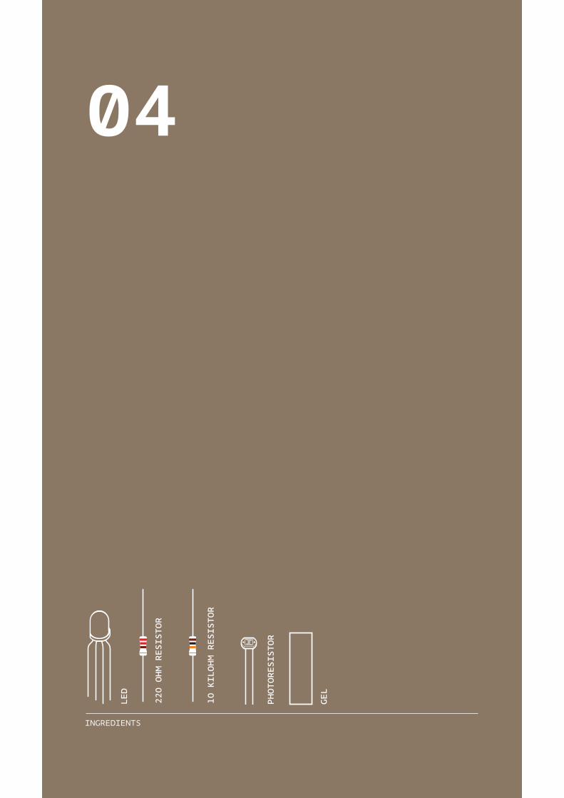
PHOTORESISTOR
GEL
220 OHM RESISTOR
10 KILOHM RESISTOR
LED
INGREDIENTS
04
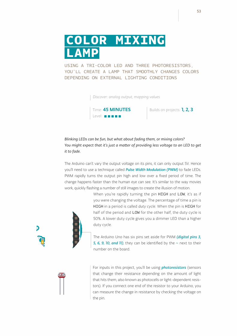
USING A TRI-COLOR LED AND THREE PHOTORESISTORS, YOU’LL CREATE A LAMP THAT SMOOTHLY CHANGES COLORS DEPENDING ON EXTERNAL LIGHTING CONDITIONS
Blinking LEDs can be fun, but what about fading them, or mixing colors? You might expect that it’s just a matter of providing less voltage to an LED to get it to fade.
The Arduino can’t vary the output voltage on its pins, it can only output 5V. Hence
you’ll need to use a technique called Pulse Width Modulation (PWM) to fade LEDs.
PWM rapidly turns the output pin high and low over a fixed period of time. The
change happens faster than the human eye can see. It’s similar to the way movies
work, quickly flashing a number of still images to create the illusion of motion.
When you’re rapidly turning the pin HIGH and LOW, it’s as if
you were changing the voltage. The percentage of time a pin is
HIGH in a period is called duty cycle. When the pin is HIGH for
half of the period and LOW for the other half, the duty cycle is
50%. A lower duty cycle gives you a dimmer LED than a higher
duty cycle.
The Arduino Uno has six pins set aside for PWM (digital pins 3, 5, 6, 9, 10, and 11), they can be identified by the ~ next to their
number on the board.
Time: 45 MINUTESLevel:
Builds on projects: 1, 2, 3
Discover: analog output, mapping values
COLOR MIXING LAMP
For inputs in this project, you’ll be using photoresistors (sensors
that change their resistance depending on the amount of light
that hits them, also known as photocells or light-dependent resis-
tors). If you connect one end of the resistor to your Arduino, you
can measure the change in resistance by checking the voltage on
the pin.
53
+ - + -
+ -+ -
BUILD THECIRCUIT
Fig. 1
Fig. 3
Fig. 2
54Color Mixing LampProject 04

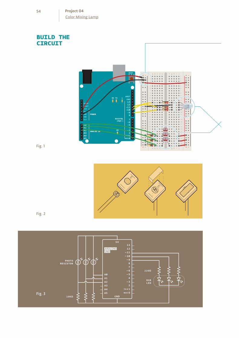
Wire up your breadboard so you have power and ground on both
sides, just like the earlier projects.
Place the three photoresistors on the breadboard so they cross
the center divide from one side to the other, as shown in Fig. 1.
Attach one end of each photoresistor to power. On the other
side, attach a 10-kilohm resistor to ground. This resistor is in se-
ries with the photoresistor, and together they form a voltage di-
vider. The voltage at the point where they meet is proportional
to the ratio of their resistances, according to Ohm’s Law (see
Project 1 for more on Ohm’s Law). As the resistance of the pho-
toresistor changes when light hits it, the voltage at this junction
changes as well. On the same side as the resistor, connect the
photoresistors to Analog In pins 0, 1, and 2 with hookup wire.
Take the three colored gels and place one over each of the pho-
toresistors. Place the red gel over the photoresistor connected
to A0, the green over the one connected to A1, and the blue over
the one connected to A2. Each of these filters lets only light of a
specific wavelength through to the sensor it’s covering. The red
filter passes only red light, the green filter passes only green light,
and the blue filter passes only blue light. This allows you to de-
tect the relative color levels in the light that hits your sensors.
The LED with 4 legs is a common cathode RGB LED. The LED has
separate red, green, and blue elements inside, and one common
ground (the cathode). By creating a voltage difference between
the cathode and the voltage coming out of the Arduino’s PWM
pins (which are connected to the anodes through 220-ohm re-
sistors), you’ll cause the LED to fade between its three colors.
Make note of what the longest pin is on the LED, place it in your
breadboard, and connect that pin to ground. Connect the other
three pins to digital pins 9, 10 and 11 in series with 220-ohm
resistors. Be sure to connect each LED lead to the correct PWM
pin, according to the figure on the left.- R B G
❶
❷
❸
❹
55
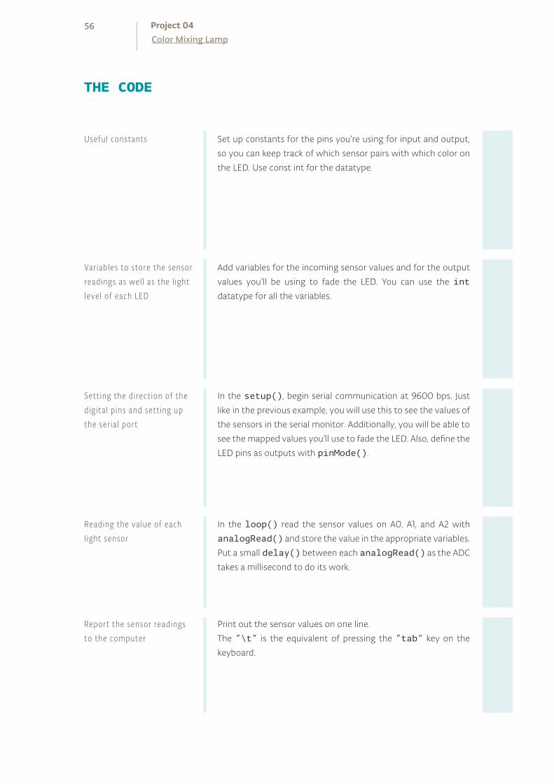
Set up constants for the pins you’re using for input and output,
so you can keep track of which sensor pairs with which color on
the LED. Use const int for the datatype.
Add variables for the incoming sensor values and for the output
values you’ll be using to fade the LED. You can use the int
datatype for all the variables.
In the setup(), begin serial communication at 9600 bps. Just
like in the previous example, you will use this to see the values of
the sensors in the serial monitor. Additionally, you will be able to
see the mapped values you’ll use to fade the LED. Also, define the
LED pins as outputs with pinMode().
In the loop() read the sensor values on A0, A1, and A2 with
analogRead() and store the value in the appropriate variables.
Put a small delay() between each analogRead() as the ADC
takes a millisecond to do its work.
Print out the sensor values on one line.
The “\t” is the equivalent of pressing the “tab” key on the
keyboard.
THE CODE
Report the sensor readings to the computer
Useful constants
Var iables to store the sensor readings as wel l as the l ight level of each LED
Sett ing the direct ion of the digita l p ins and sett ing up the ser ia l port
Reading the value of each l ight sensor
56Color Mixing LampProject 04

1
2
3
4
5
6
7
8
9
const int greenLEDPin = 9;
const int redLEDPin = 11;
const int blueLEDPin = 10;
const int redSensorPin = A0;
const int greenSensorPin = A1;
const int blueSensorPin = A2;
int redValue = 0;
int greenValue = 0;
int blueValue = 0;
int redSensorValue = 0;
int greenSensorValue = 0;
int blueSensorValue = 0;
void setup()
Serial.begin(9600);
pinMode(greenLEDPin,OUTPUT);
pinMode(redLEDPin,OUTPUT);
pinMode(blueLEDPin,OUTPUT);
void loop()
redSensorValue = analogRead(redSensorPin);
delay(5);
greenSensorValue = analogRead(greenSensorPin);
delay(5);
blueSensorValue = analogRead(blueSensorPin);
Serial.print(“Raw Sensor Values \t Red: “);
Serial.print(redSensorValue);
Serial.print(“\t Green: “);
Serial.print(greenSensorValue);
Serial.print(“\t Blue: “);
Serial.println(blueSensorValue);
10
11
12
13
14
19
20
21
22
23
24
25
26
27
28
29
30
15
16
17
18
57

The function to change the LED’s brightness via PWM is called
analogWrite(). It needs two arguments: the pin to write to,
and a value between 0-255. This second number represents the
duty cycle the Arduino will output on the specified pin. A value of
255 will set the pin HIGH all the time, making the attached LED
as bright as it can be. A value of 127 will set the pin HIGH half
the time of the period, making the LED dimmer. 0 would set the
pin LOW all the time, turning the LED off. To convert the sensor
reading from a value between 0-1023 to a value between 0-255
for analogWrite(), divide the sensor reading by 4.
Print out the new mapped values on their own line.
Once you have your Arduino programmed and wired up, open
the serial monitor. The LED will probably be an off-white
color, depending on the predominant color of the light in your
room. Look at the values coming from the sensors in the serial
monitor, if you’re in an environment with stable lighting, the
number should probably be fairly consistent.
Turn off the light in the room you’re in and see what happens
to the values of the sensors. With a flashlight, illuminate each
of the sensors individually and notice how the values change
in the serial monitor, and notice how the LED’s color changes.
When the photoresistors are covered with a gel, they only re-
act to light of a certain wavelength. This will give you the op-
portunity to change each of the colors independently.
USE IT
Convert ing the sensor readings
Report the calculated LED l ight levels
Set the LED l ight levels
58Color Mixing LampProject 04

redValue = redSensorValue/4;
greenValue = greenSensorValue/4;
blueValue = blueSensorValue/4;
Serial.print(“Mapped Sensor Values \t Red: “);
Serial.print(redValue);
Serial.print(“\t Green: “);
Serial.print(greenValue);
Serial.print(“\t Blue: “);
Serial.println(blueValue);
analogWrite(redLEDPin, redValue);
analogWrite(greenLEDPin, greenValue);
analogWrite(blueLEDPin, blueValue);
31
32
33
34
35
36
37
38
39
40
41
42
43
You may notice that the photoresistor’s output doesn’t range all the way from 0 to 1023. That’s okay for this project, but for a more detailed explanation of how to calibrate for the range you’re reading, see Project 6.
How could you use this to let you know if it’s a nice day outside while you’re working
inside? What other sorts of sensors can you use to control the LED’s color?
You’ll probably notice that the LED’s fading is not linear. When the LED is about at
half brightness, it appears to stop getting much brighter. This is because our eyes
don’t perceive brightness linearly. The brightness of the light depends not only on
the level that you analogWrite() but also on the distance of the light from the
diffuser, the distance of your eye from the light, and the brightness of the light rela-
tive to other light in the room.
59
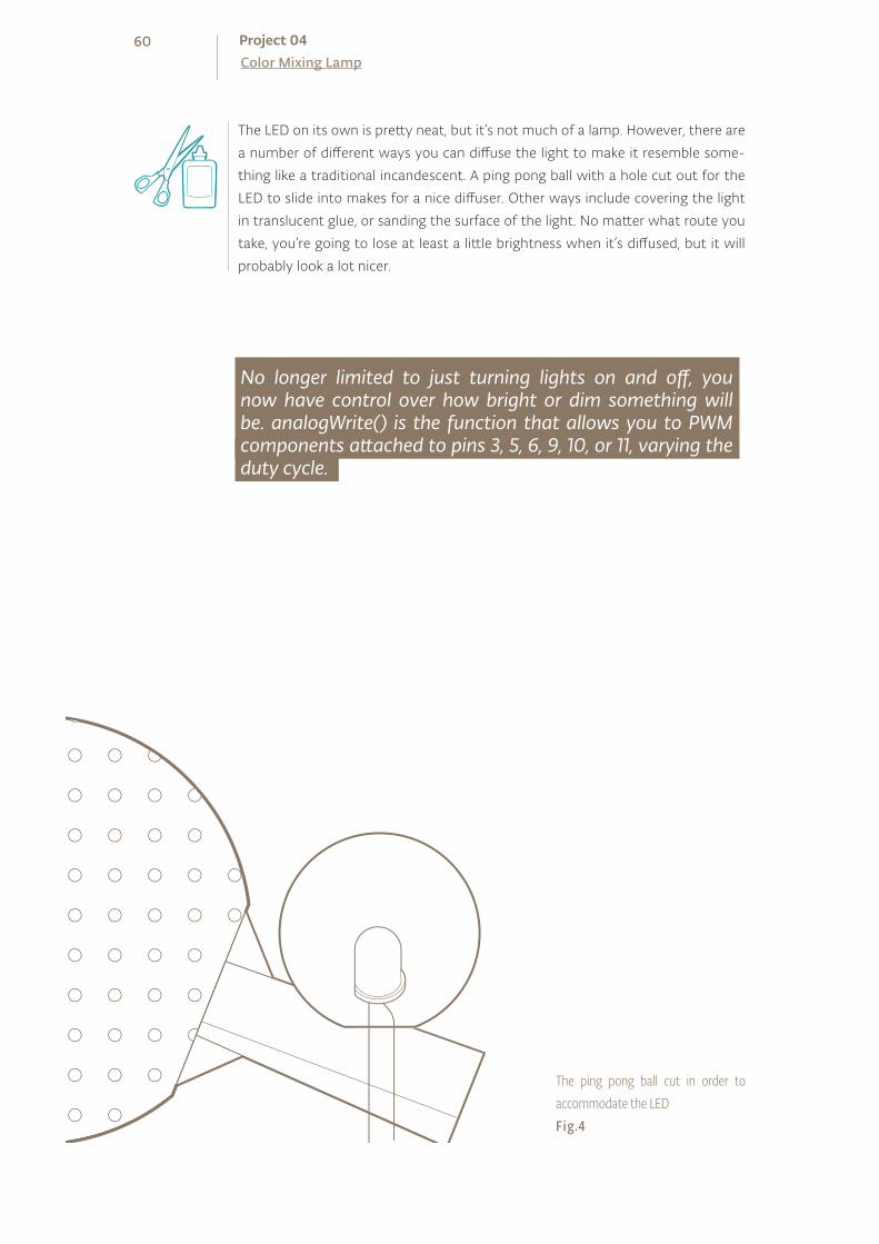
No longer limited to just turning lights on and off, you now have control over how bright or dim something will be. analogWrite() is the function that allows you to PWM components attached to pins 3, 5, 6, 9, 10, or 11, varying the duty cycle.
The LED on its own is pretty neat, but it’s not much of a lamp. However, there are
a number of different ways you can diffuse the light to make it resemble some-
thing like a traditional incandescent. A ping pong ball with a hole cut out for the
LED to slide into makes for a nice diffuser. Other ways include covering the light
in translucent glue, or sanding the surface of the light. No matter what route you
take, you’re going to lose at least a little brightness when it’s diffused, but it will
probably look a lot nicer.
The ping pong ball cut in order to accommodate the LEDFig.4
60Color Mixing LampProject 04


POTENTIOMETER
MOTOR ARM
SERVO MOTOR
100UF CAPACITOR
INGREDIENTS
MALE HEADER PIN (3 pins)
05
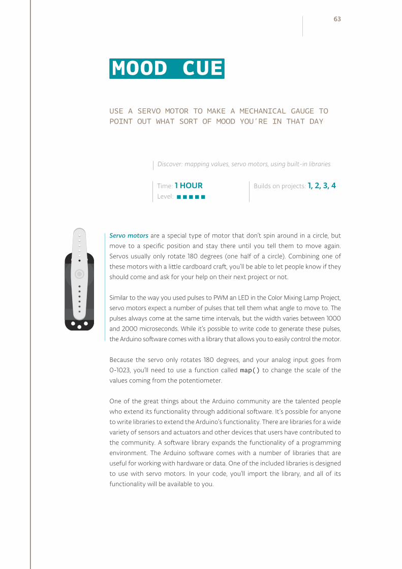
USE A SERVO MOTOR TO MAKE A MECHANICAL GAUGE TO POINT OUT WHAT SORT OF MOOD YOU’RE IN THAT DAY
Servo motors are a special type of motor that don’t spin around in a circle, but
move to a specific position and stay there until you tell them to move again.
Servos usually only rotate 180 degrees (one half of a circle). Combining one of
these motors with a little cardboard craft, you’ll be able to let people know if they
should come and ask for your help on their next project or not.
Similar to the way you used pulses to PWM an LED in the Color Mixing Lamp Project,
servo motors expect a number of pulses that tell them what angle to move to. The
pulses always come at the same time intervals, but the width varies between 1000
and 2000 microseconds. While it’s possible to write code to generate these pulses,
the Arduino software comes with a library that allows you to easily control the motor.
Because the servo only rotates 180 degrees, and your analog input goes from
0-1023, you’ll need to use a function called map() to change the scale of the
values coming from the potentiometer.
One of the great things about the Arduino community are the talented people
who extend its functionality through additional software. It’s possible for anyone
to write libraries to extend the Arduino’s functionality. There are libraries for a wide
variety of sensors and actuators and other devices that users have contributed to
the community. A software library expands the functionality of a programming
environment. The Arduino software comes with a number of libraries that are
useful for working with hardware or data. One of the included libraries is designed
to use with servo motors. In your code, you’ll import the library, and all of its
functionality will be available to you.
Time: 1 HOURLevel:
Builds on projects: 1, 2, 3, 4
Discover: mapping values, servo motors, using built-in libraries
MOOD CUE
63
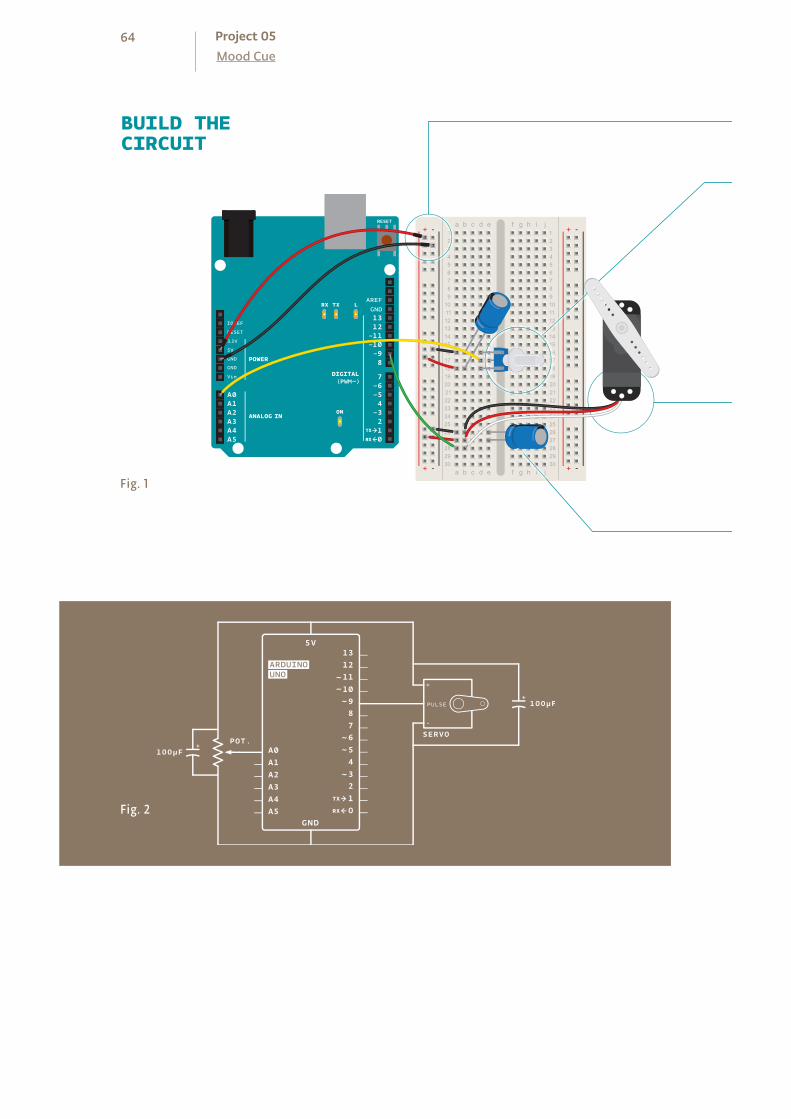
BUILD THECIRCUIT
Fig. 1
Fig. 2
64Mood CueProject 05
+ - + -
+ -+ -

Attach 5V and ground to one side of your breadboard from the
Arduino.
Place a potentiometer on the breadboard, and connect one side
to 5V, and the other to ground. A potentiometer is a type of volt-
age divider. As you turn the knob, you change the ratio of the
voltage between the middle pin and power. You can read this
change on an analog input. Connect the middle pin to analog pin
0. This will control the position of your servo motor.
The servo has three wires coming out of it. One is power (red),
one is ground (black), and the third (white) is the control line that
will receive information from the Arduino. Plug three male head-
ers into the female ends of the servo wires (see Fig. 3). Connect
the headers to your breadboard so that each pin is in a different
row. Connect 5V to the red wire, ground to the black wire, and
the white wire to pin 9.
When a servo motor starts to move, it draws more current than
if it were already in motion. This will cause a dip in the voltage
on your board. By placing a 100uf capacitor across power and
ground right next to the male headers as shown in Fig. 1, you can
smooth out any voltage changes that may occur. You can also
place a capacitor across the power and ground going into your
potentiometer. These are called decoupling capacitors because
they reduce, or decouple, changes caused by the components
from the rest of the circuit. Be very careful to make sure you are
connecting the cathode to ground (that’s the side with a black
stripe down the side) and the anode to power. If you put the
capacitors in backwards, they can explode.
Your servo motor comes with female connectors , so you’ l l need to add header pins to connect i t to the breadboard.Fig. 3
❶
❷
❸
❹
65
To use the servo library, you’ll first need to import it. This makes
the additions from the library available to your sketch.
To refer to the servo, you’re going to need to create a named
instance of the servo library in a variable. This is called an object.
When you do this, you’re making a unique name that will have all
the functions and capabilities that the servo library offers. From
this point on in the program, every time you refer to myServo,
you’ll be talking to the servo object.
Set up a named constant for the pin the potentiometer is
attached to, and variables to hold the analog input value and
angle you want the servo to move to.
In the setup(), you’re going to need to tell the Arduino what
pin your servo is attached to.
Include a serial connection so you can check the values from the
potentiometer and see how they map to angles on the servo
motor.
In the loop(), read the analog input and print out the value to
the serial monitor.
To create a usable value for the servo motor from your analog
input, it’s easiest to use the map() function. This handy function
scales numbers for you. In this case it will change values between
0-1023 to values between 0-179. It takes five arguments : the
number to be scaled (here it’s potVal), the minimum value of the
input (0), the maximum value of the input (1023), the minimum
value of the output (0), and the maximum value of the output
(179). Store this new value in the angle variable.
Then, print out the mapped value to the serial monitor.
Finally, it’s time to move the servo. The command servo.
write() moves the motor to the angle you specify.
At the end of the loop() put a delay so the servo has time to
move to its new position.
THE CODE
Mapping potentiometer value to the servo values
Rotat ing the servo
Import the l ibrary
Creat ing the Servo object
Var iable declarat ion
Associat ing the Servo object with the Arduino pin , in it ia l iz ing the ser ia l port
Reading the potentiometer value
66Mood CueProject 05
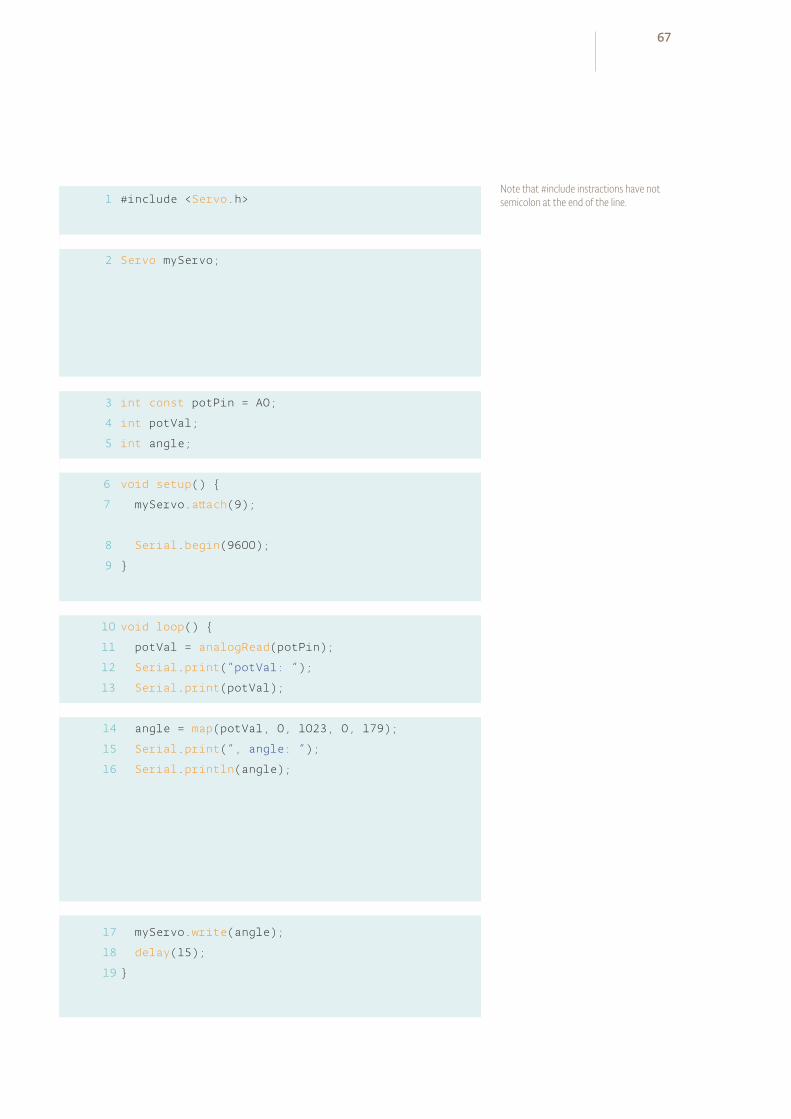
1
2
#include <Servo.h>
Servo myServo;
int const potPin = A0;
int potVal;
int angle;
void setup()
myServo.attach(9);
Serial.begin(9600);
void loop()
potVal = analogRead(potPin);
Serial.print(“potVal: “);
Serial.print(potVal);
angle = map(potVal, 0, 1023, 0, 179);
Serial.print(“, angle: “);
Serial.println(angle);
myServo.write(angle);
delay(15);
3
4
5
6
7
8
9
10
11
12
13
14
15
16
17
18
19
Note that #include instractions have not semicolon at the end of the line.
67

Once your Arduino has been programmed and powered up,
open the serial monitor. You should see a stream of values
similar to this:
potVal : 1023, angle : 179
potVal : 1023, angle : 179
When you turn the potentiometer, you should see the num-
bers change. More importantly, you should see your servo
motor move to a new position. Notice the relationship be-
tween the value of potVal and angle in the serial monitor and
the position of the servo. You should see consistent results as
you turn the pot.
One nice thing about using potentiometers as analog inputs
is that they will give you a full range of values between 0 and
1023. This makes them helpful in testing projects that use
analog input.
USE IT
Servo motors are regular motors with a number of gears and some circuits inside.
The mechanics inside provide feedback to the circuit, so it is always aware of its posi-
tion. While it may seem like this is a limited range of motion, it’s possible to get it to
make a wide variety of different kinds of movements with some additional mechanics.
There are a number of resources that describe mechanisms in detail like robives.com/mechs and the book Making Things Move by Dustyn Roberts.
The potentiometer is not the only sensor you can use for controlling the servo.
Using the same physical setup (an arrow pointing to a number of different indi-
cators) and a different sensor, what sort of indicator can you make? How would
this work with temperature (like in the Love-o-Meter)? Could you tell the time
of day with a photoresistor? How does mapping values come into play with
those types of sensors?
Servo motors can easily be controlled by the Arduino using a library, which is a collection of code that extends a programming environment. Sometimes it is necessary to repurpose values by mapping them from one scale to another.
68Mood CueProject 05

Now that you’re up and running with motion, it’s time to let people know if you’re
available to help them on their projects, or if you want to be left alone to plan
your next creation.
With scissors, cut out a piece of cardboard in the shape of an arrow. Position your
servo to 90 degrees (check the angle value in the serial monitor if you’re unsure).
Tape the arrow so it’s oriented in the same direction as the motor’s body. Now you
should be able to rotate the arrow 180 degrees when turning the potentiometer.
Take a piece of paper that is larger than the servo with the arrow attached and
draw a half circle on it. On one end of the circle, write “Stay Out”. On the other end,
write “Come in”. Put “Knock please!” in the middle of the arc. Place the servo with
the arrow on top of the paper. Congratulations, you’ve got a way to tell people just
how busy you are with your projects!
COME IN
KNOCK PLEASE
STAY OUTCOME IN
KNOCK PLEASE
STAY OUT
❶
Attach a paper arrow to the servo arm.
❷
Design a paper base and place it under the servo.
69

INGREDIENTS
10 KILOHM RESISTOR
PHOTORESISTOR
PIEZO
06

TIME TO MAKE SOME NOISE! USING A PHOTORESISTOR AND A PIEZO ELEMENT, YOU’RE GOING TO MAKE A LIGHT-BASED THEREMIN
A theremin is an instrument that makes sounds based on the movements of
a musician’s hands around the instrument. You’ve probably heard one in scary
movies. The theremin detects where a performer’s hands are in relation to two
antennas by reading the capacitive change on the antennas. These antennas are
connected to analog circuitry that create the sound. One antenna controls the
frequency of the sound and the other controls volume. While the Arduino can’t
exactly replicate the mysterious sounds from this instrument, it is possible to
emulate them using the tone() function. Fig. 1 shows the difference between
the pulses emitted by analogWrite() and tone(). This enables a transducer
like a speaker or piezo to move back and forth at different speeds.
Time: 45 MINUTESLevel:
Builds on projects: 1, 2, 3, 4
Discover: making sound with the tone() function, calibrating analog sensors
LIGHT THEREMIN
Fig. 1 10 MILLISECONDS
Notice how the voltage is high most of the
time, but the frequency is the same as PWM 50.
PWM 200: analogWrite(200)PERIOD
0
5
PERIOD
Notice how the signal is low most of the time,
but the frequency is the same as PWM 200.
PWM 50: analogWrite(50)
0
5
The duty cycle is 50% (on half the time, off half
the time), but the frequency changes.
TONE 440: tone(9,440)
0
5
PERIOD
Same duty cycle as Tone 440; but twice the
frequency.
TONE 880: tone(9,880)
0
5
PERIOD
71
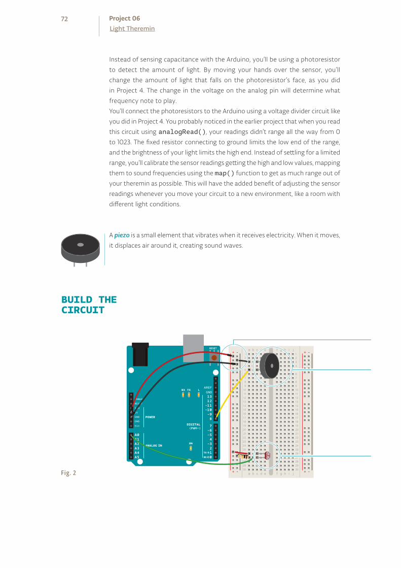
+ - + -
+ -+ -
Instead of sensing capacitance with the Arduino, you’ll be using a photoresistor
to detect the amount of light. By moving your hands over the sensor, you’ll
change the amount of light that falls on the photoresistor’s face, as you did
in Project 4. The change in the voltage on the analog pin will determine what
frequency note to play.
You’ll connect the photoresistors to the Arduino using a voltage divider circuit like
you did in Project 4. You probably noticed in the earlier project that when you read
this circuit using analogRead(), your readings didn’t range all the way from 0
to 1023. The fixed resistor connecting to ground limits the low end of the range,
and the brightness of your light limits the high end. Instead of settling for a limited
range, you’ll calibrate the sensor readings getting the high and low values, mapping
them to sound frequencies using the map() function to get as much range out of
your theremin as possible. This will have the added benefit of adjusting the sensor
readings whenever you move your circuit to a new environment, like a room with
different light conditions.
A piezo is a small element that vibrates when it receives electricity. When it moves,
it displaces air around it, creating sound waves.
BUILD THECIRCUIT
Fig. 2
72Light ThereminProject 06
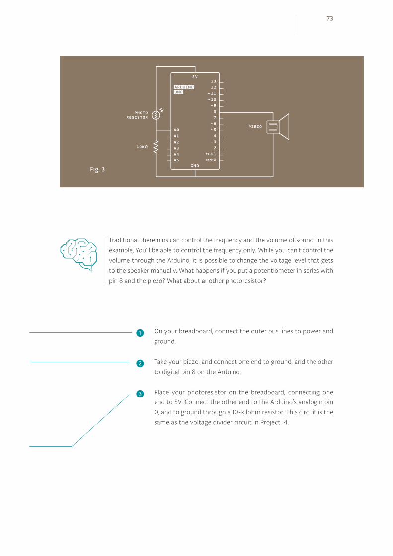
Fig. 3
On your breadboard, connect the outer bus lines to power and
ground.
Take your piezo, and connect one end to ground, and the other
to digital pin 8 on the Arduino.
Place your photoresistor on the breadboard, connecting one
end to 5V. Connect the other end to the Arduino’s analogIn pin
0, and to ground through a 10-kilohm resistor. This circuit is the
same as the voltage divider circuit in Project 4.
Traditional theremins can control the frequency and the volume of sound. In this
example, You’ll be able to control the frequency only. While you can’t control the
volume through the Arduino, it is possible to change the voltage level that gets
to the speaker manually. What happens if you put a potentiometer in series with
pin 8 and the piezo? What about another photoresistor?
❶
❷
❸
73
Create a variable to hold the analogRead() value from the
photoresistor. Next, create variables for the high and low values.
You’re going to set the initial value in the sensorLow variable to
1023, and set the value of the sensorHigh variable to 0. When
you first run the program, you’ll compare these numbers to the
sensor’s readings to find the real maximum and minimum values.
Create a constant named ledPin. You’ll use this as an indicator
that your sensor has finished calibrating. For this project, use the
on-board LED connected to pin 13.
In the setup(), change the pinMode() of ledPin to OUTPUT,
and turn the light on.
The next steps will calibrate the sensor’s maximum and minimum
values. You’ll use a while() statement to run a loop for 5
seconds. while() loops run until a certain condition is met. In
this case you’re going to use the millis() function to check
the current time. millis() reports how long the Arduino has
been running since it was last powered on or reset.
In the loop, you’ll read the value of the sensor; if the value is less
than sensorLow (initially 1023), you’ll update that variable. If
it is greater than sensorHigh (initially 0), that gets updated.
When 5 seconds have passed, the while() loop will end. Turn off
the LED attached to pin 13. You’ll use the sensor high and low
values just recorded to scale the frequency in the main part of
your program.
THE CODE
Create var iables for cal ibrat ing the sensor
Name a constant for your cal ibrat ion indicator
Set digita l p in direct ion and turn it h igh
Use a whi le() loop for cal ibrat ion
Compare sensor values for cal ibrat ion
Indicate cal ibrat ion has f in ished
74Light ThereminProject 06
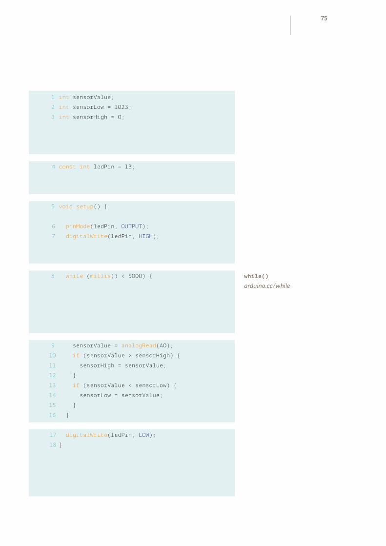
1
2
3
4
5
int sensorValue;
int sensorLow = 1023;
int sensorHigh = 0;
const int ledPin = 13;
void setup()
pinMode(ledPin, OUTPUT);
digitalWrite(ledPin, HIGH);
while (millis() < 5000)
sensorValue = analogRead(A0);
if (sensorValue > sensorHigh)
sensorHigh = sensorValue;
if (sensorValue < sensorLow)
sensorLow = sensorValue;
digitalWrite(ledPin, LOW);
8
9
10
11
12
13
14
15
16
17
18
6
7
while()
arduino.cc/while
75

In the loop(), read the value on A0 and store it in sensorValue.
Create a variable named pitch. The value of pitch is going
to be mapped from sensorValue. Use sensorLow and
sensorHigh as the bounds for the incoming values. For starting
values for output, try 50 to 4000. These numbers set the range
of frequencies the Arduino will generate.
Next, call the tone() function to play a sound. It takes three
arguments : what pin to play the sound on (in this case pin 8),
what frequency to play (determined by the pitch variable), and
how long to play the note (try 20 milliseconds to start).
Then, call a delay() for 10 milliseconds to give the sound some
time to play.
When you first power the Arduino on, there is a 5 second win-
dow for you to calibrate the sensor. To do this, move your
hand up and down over the photoresistor, changing the
amount of light that reaches it. The closer you replicate the
motions you expect to use while playing the instrument, the
better the calibration will be.
After 5 seconds, the calibration will be complete, and the LED
on the Arduino will turn off. When this happens, you should
hear some noise coming from the piezo! As the amount of
light that falls on the sensor changes, so should the frequency
that the piezo plays.
USE IT
Read and store the sensor value
Map the sensor value to a frequency
Play the frequency
76Light ThereminProject 06
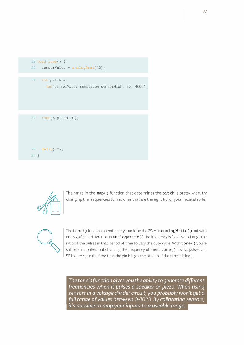
void loop()
sensorValue = analogRead(A0);
int pitch =
map(sensorValue,sensorLow,sensorHigh, 50, 4000);
tone(8,pitch,20);
delay(10);
19
20
21
22
23
24
The range in the map() function that determines the pitch is pretty wide, try
changing the frequencies to find ones that are the right fit for your musical style.
The tone() function operates very much like the PWM in analogWrite() but with
one significant difference. In analogWrite() the frequency is fixed; you change the
ratio of the pulses in that period of time to vary the duty cycle. With tone() you’re
still sending pulses, but changing the frequency of them. tone() always pulses at a
50% duty cycle (half the time the pin is high, the other half the time it is low).
The tone() function gives you the ability to generate different frequencies when it pulses a speaker or piezo. When using sensors in a voltage divider circuit, you probably won’t get a full range of values between 0-1023. By calibrating sensors, it’s possible to map your inputs to a useable range.
77
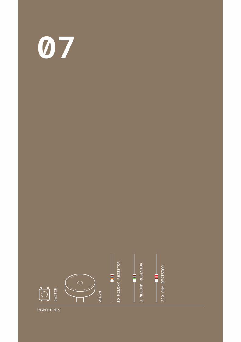
INGREDIENTS
10 KILOHM RESISTOR
1 MEGOHM RESISTOR
220 OHM RESISTOR
SWITCH
PIEZO
07
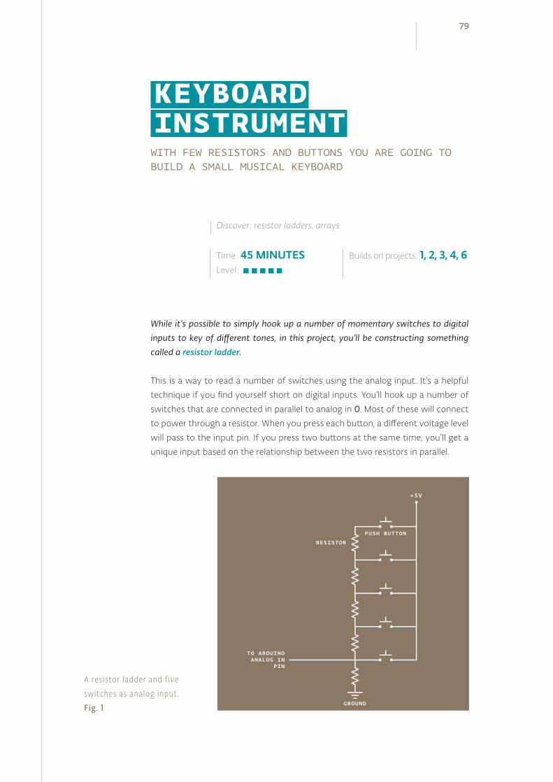
WITH FEW RESISTORS AND BUTTONS YOU ARE GOING TO BUILD A SMALL MUSICAL KEYBOARD
While it’s possible to simply hook up a number of momentary switches to digital inputs to key of different tones, in this project, you’ll be constructing something called a resistor ladder.
This is a way to read a number of switches using the analog input. It’s a helpful
technique if you find yourself short on digital inputs. You’ll hook up a number of
switches that are connected in parallel to analog in 0. Most of these will connect
to power through a resistor. When you press each button, a different voltage level
will pass to the input pin. If you press two buttons at the same time, you’ll get a
unique input based on the relationship between the two resistors in parallel.
Time: 45 MINUTESLevel:
Builds on projects: 1, 2, 3, 4, 6
Discover: resistor ladders, arrays
KEYBOARD INSTRUMENT
A res istor ladder and f ive switches as analog input .Fig. 1
79
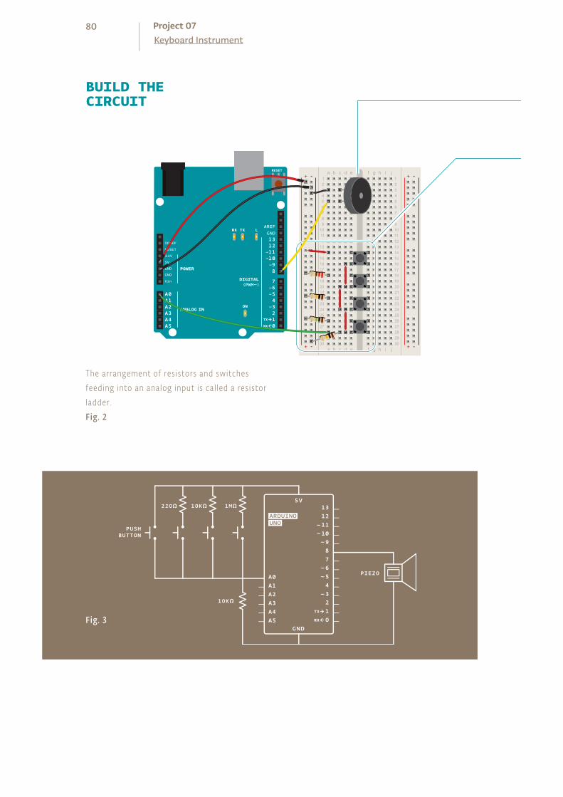
+ - + -
+ -+ -
BUILD THECIRCUIT
The arrangement of res istors and switches feeding into an analog input is cal led a res istor ladder. Fig. 2
Fig. 3
80Keyboard InstrumentProject 07

Wire up your breadboard with power and ground as in the
previous projects. Connect one end of the piezo to ground.
Connect the other end to pin 8 on your Arduino.
Place your switches on the breadboard as shown in the circuit.
The arrangement of resistors and switches feeding into an
analog input is called a resistor ladder. Connect the first one
directly to power. Connect the second, third and fourth switches
to power through a 220-ohm, 10-kilohm and 1-megohm resistor,
respectively. Connect all the switches’ outputs together in one
junction. Connect this junction to ground with a 10-kilohm
resistor, and also connect it to Analog In 0. Each of these acts as
a voltage divider.
Think about an enclosure for the keyboard. While old analog synthesizers had
wires poking out all over the place, your keyboard is sleek and digital. Prepare a
small piece of cardboard that can be cut out to accommodate your buttons. Label
the keys, so you know what notes are triggered by each key.
❶
❷
❶
Draw and cut a piece of paper with holes for the four buttons and piezo. Decorate it to look like a piano keyboard.
❷
Position the paper over the buttons and piezo.Enjoy your creation!
81
In this program, you’ll need to keep a list of frequencies you want
to play when you press each of your buttons. You can start out
with the frequencies for middle C, D, E and F (262Hz, 294Hz,
330Hz, and 349Hz). To do this, you’ll need a new kind of variable
called an array.
An array is a way to store different values that are related to
each other, like the frequencies in a musical scale, using only
one name. They are a convenient tool for you to quickly and
efficiently access information. To declare an array, start as you
would with a variable, but follow the name with a pair of square
brackets: []. After the equals sign, you’ll place your elements in
curly brackets.
To read or change the elements of the array, you reference the
individual element using the array name and then the index of
the item you want to address. The index refers to the order in
which the items appear when the array is created. The first item
in the array is item 0, the second is item 1, and so forth.
Set up an array of four notes using the frequencies listed above.
Make this array a global variable by declaring it before the
setup().
In your setup(), start serial communication with the computer.
In the loop(), declare a local variable to hold the value
read on pin A0. Because each switch has a different resistor
value connecting it to power, each will have a different value
associated with it. To see the values, add the line Serial.
println(keyVal) to send to the computer.
Using an if()...else statement, you can assign each value to a
different tone. The values included in the example program are
ballpark figures for these resistor sizes. As all resistors have some
tolerance for error, these may not work exactly for you. Use the
information from the serial monitor to adjust as necessary.
THE CODE
The array
Create an array of frequencies
Begin ser ia l communicat ion
Read the analog value and send it to the ser ia l monitor
Use an if(). . .else statement to determine what note to play
82Keyboard InstrumentProject 07
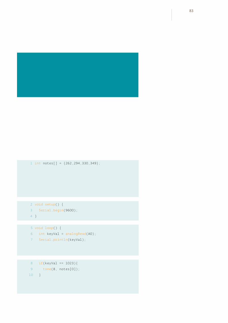
int buttons[6];
// set up an array with 6 integers
int buttons[0] = 2;
// give the first element of the array the value 2
int notes[] = 262,294,330,349;
void setup()
Serial.begin(9600);
void loop()
int keyVal = analogRead(A0);
Serial.println(keyVal);
if(keyVal == 1023)
tone(8, notes[0]);
1
2
3
4
5
6
7
8
9
10
83
After each if() statement, call the tone() function. The
program references the array to determine what frequency
to play. If the value of A0 matches one of your if statements,
you can tell the Arduino to play a tone. It’s possible your circuit
is a little “noisy” and the values may fluctuate a little bit while
pressing a switch. To accommodate for this variation, it’s a good
idea to have a small range of values to check against. If you use
the comparison “&&”, you can check multiple statements to see
if they are true.
If you press the first button, notes[0] will play. If you press the
second, notes[1] will play, and if you press the third, notes[2] will
play. This is when arrays become really handy.
Only one frequency can play on a pin at any given time, so if
you’re pressing multiple keys, you’ll only hear one sound.
To stop playing notes when there is no button being pressed,
call the noTone() function, providing the pin number to stop
playing sound on.
If your resistors are close in value to the values in the example
program, you should hear some sounds from the piezo when
you press the buttons. If not, check the serial monitor to make
sure each of the buttons is in a range that corresponds to the
notes in the if()...else statement. If you’re hearing a sound
that seems to stutter, try increasing the range a little bit.
Press multiple buttons at the same time, and see what sort of
values you get in the serial monitor. Use these new values to
trigger even more sounds. Experiment with different frequencies
to expand your musical output. You can find frequencies of
musical notes on this page: arduino.cc/frequencies
USE IT
Play the notes that correspond to the analog value
Stop playing the tone when nothing is pressed
If you replace the switches and resistor ladder with analog sensors, can you use the
additional information they give you to create a more dynamic instrument? You
could use the value to change the duration of a note or, like in the Theremin Project,
create a sliding scale of sounds.
84Keyboard InstrumentProject 07

else if(keyVal >= 990 && keyVal <= 1010)
tone(8, notes[1]);
else if(keyVal >= 505 && keyVal <= 515)
tone(8, notes[2]);
else if(keyVal >= 5 && keyVal <= 10)
tone(8, notes[3]);
else
noTone(8);
The tone() function is fun for generating sounds, but it does have a few limi-
tations. It can only create square waves, not smooth sine waves or triangles.
Square waves don’t look much like waves at all. As you saw in Fig. 1 in Project 6,
it’s a series of on and off pulses.
As you start your band, keep some things in mind : only one tone can play at a time
and tone() will interfere with analogWrite() on pins 3 and 11.
Arrays are useful for grouping similar types of information together; they are accessed by index numbers which refer to individual elements. Resistor ladders are an easy way to get more digital inputs into a system by plugging into an analog input.
11
12
13
14
15
16
17
18
19
20
21
22
23
85

INGREDIENTS
10 KILOHM RESISTOR
220 OHM RESISTOR
SWITCH
LED
08
IN THIS PROJECT, YOU’LL BUILD A DIGITAL HOURGLASS THAT TURNS ON AN LED EVERY TEN MINUTES. KNOW HOW LONG YOU’RE WORKING ON YOUR PROJECTS BY USING THE ARDUINO’S BUILT-IN TIMER
Up to now, when you’ve wanted something to happen at a specific time interval with the Arduino, you’ve used delay(). This is handy, but a little confining. When the Arduino calls delay(), it freezes its current state for the duration of the delay. That means there can be no other input or output while it’s waiting. Delays are also not very helpful for keeping track of time. If you wanted to do something every 10 seconds, having a 10 second delay would be fairly cumbersome.
The millis() function helps to solve these problems. It keeps track of the time
your Arduino has been running in milliseconds. You used it previously in Project 6
when you created a timer for calibration.
So far you’ve been declaring variables as int. An int (integer) is a 16-bit number,
it holds values between -32,768 and 32,767. Those may be some large numbers,
but if the Arduino is counting 1000 times a second with millis(), you’d run out
of space in less than a minute. The long datatype holds a 32-bit number (between
-2,147,483,648 and 2,147,483,647). Since you can’t run time backwards to get
negative numbers, the variable to store millis() time is called an unsigned
long. When a datatype is called unsigned, it is only positive. This allows you to
count even higher. An unsigned long can count up to 4,294,967,295. That’s
enough space for milis() to store time for almost 50 days. By comparing the
current millis() to a specific value, you can see if a certain amount of time has
passed.
When you turn your hourglass over, a tilt switch will change its state, and that will
set off another cycle of LEDs turning on.
The tilt switch works just like a regular switch in that it is an on/off sensor. You’ll
use it here as a digital input. What makes tilt switches unique is that they detect
orientation. Typically they have a small cavity inside the housing that has a metal
Time: 30 MINUTESLevel:
Builds on projects: 1, 2, 3, 4
Discover: long data type, creating a timer
DIGITAL HOURGLASS
87
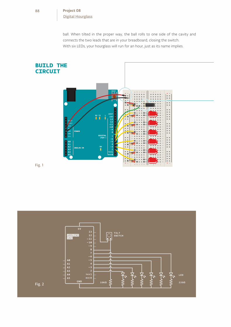
ball. When tilted in the proper way, the ball rolls to one side of the cavity and
connects the two leads that are in your breadboard, closing the switch.
With six LEDs, your hourglass will run for an hour, just as its name implies.
BUILD THECIRCUIT
Fig. 1+ - + -
+ -+ -
+ - + -
+ -+ -
Fig. 2
88Digital HourglassProject 08

Connect power and ground to your breadboard.
Connect the anode (longer leg) of six LEDs to digital pins 2-7.
Connect the LEDs to ground through 220-ohm resistors.
Connect one lead of the tilt switch to 5V. Connect the other to
a 10-kilohm resistor to ground. Connect the junction where they
meet to digital pin 8.
Tilt switches are great, inexpensive tools for determining the orientation of some-
thing. Accelerometers are another type of tilt sensor, but they give out much more
information. They are also significantly more expensive. If you’re just looking to see if
something is up or down, a tilt sensor works great.
You don’t need to have your Arduino tethered to the computer for this to work.
Try building a stand with some cardboard or styrofoam and power the Arduino
with a battery to make a portable version. You can create a cover with some nu-
meric indicators alongside the lights.
❶❷
❸
89
You’re going to need a number of global variables in your
program to get this all working. To start, create a constant named
switchPin. This will be the name of the pin your tilt switch is on.
Create a variable of type unsigned long, This will hold the time
an LED was last changed.
Create a variable for the switch state, and another to hold the
previous switch state. You’ll use these two to compare the
switch’s position from one loop to the next.
Create a variable named led. This will be used to count which LED
is the next one to be turned on. Start out with pin 2.
The last variable you’re creating is going to be the interval
between each LED turning on. This will be be a long datatype.
In 10 minutes (the time between each LED turning on) 600,000
milliseconds pass. If you want the delay between lights to be
longer or shorter, this is the number you change.
In your setup(), you need to declare the LED pins 2-7 as
outputs. A for() loop declares all six as OUTPUT with just 3 lines
of code. You also need to declare switchPin as an INPUT.
When the loop() starts, you’re going to get the amount of time
the Arduino has been running with millis() and store it in a
local variable named currentTime.
Using an if() statement, you’ll check to see if enough time has
passed to turn on an LED. Subtract the currentTime from the
previousTime and check to see if it is greater than the interval
variable. If 600,000 milliseconds have passed (10 minutes), you’ll
set the variable previousTime to the value of currentTime.
THE CODE
Set the direct ion of your digita l p ins
Check the t ime s ince the program started running
Evaluate the amount of t ime that has passed s ince the previous loop()
Declare a named constant
Create a variable to hold the time
Name variables for the inputs and outputs
Declare a variable describing the interval between events
90Digital HourglassProject 08
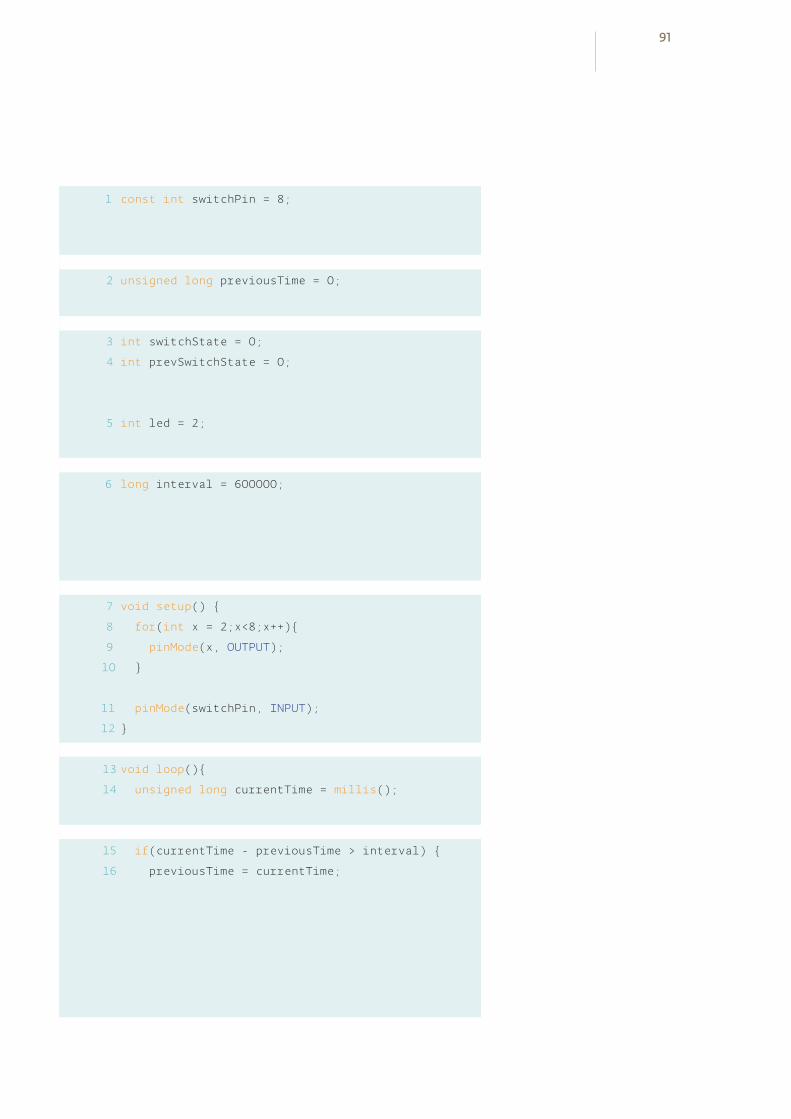
1
2
3
4
const int switchPin = 8;
unsigned long previousTime = 0;
int switchState = 0;
int prevSwitchState = 0;
int led = 2;
long interval = 600000;
void setup()
for(int x = 2;x<8;x++)
pinMode(x, OUTPUT);
pinMode(switchPin, INPUT);
void loop()
unsigned long currentTime = millis();
if(currentTime - previousTime > interval)
previousTime = currentTime;
6
7
8
9
10
11
12
5
13
14
15
16
91

previousTime indicates the last time an LED was turned on.
Once you’ve set previousTime, turn on the LED, and increment
the led variable. The next time you pass the time interval, the
next LED will light up.
Add one more if statement in the program to check if the LED on
pin 7 is turned on. Don’t do anything with this yet. You’ll decide
what happens at the end of the hour later.
Now that you’ve checked the time, you’ll want to see if the
switch has changed its state. Read the switch value into the
switchState variable.
With an if() statement, check to see if the switch is in a different
position than it was previously. The != evaluation checks to see
if switchState does not equal prevSwitchState. If they
are different, turn the LEDs off, return the led variable to the first
pin, and reset the timer for the LEDs by setting previousTime
to currentTime.
At the end of the loop(), save the switch state in
prevSwitchState , so you can compare it to the value you
get for switchState in the next loop().
Reset the var iables to their defaults i f necessary
Once you’ve programmed the board, check the time on a
clock. After 10 minutes have passed, the first LED should have
turned on. Every 10 minutes after that, a new light will turn
on. At the end of an hour, all six light should be on. When
you flip the circuit over, and cause the tilt switch to change
its state, the lights will turn off and the timer will start again.
USE IT
Turn on an LED, prepare for the next one
Check to see i f a l l l ights are on
Read the value of the switch
Set the current state to the previous state
92Digital HourglassProject 08
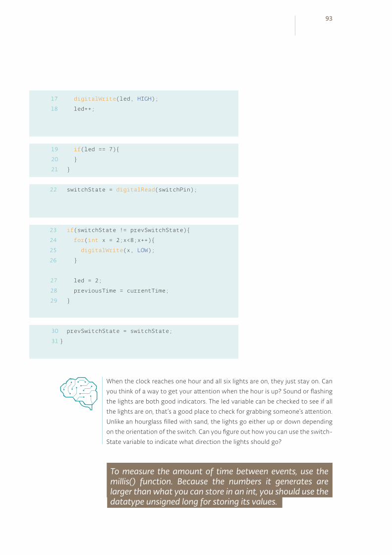
17
18
19
20
21
digitalWrite(led, HIGH);
led++;
if(led == 7)
switchState = digitalRead(switchPin);
if(switchState != prevSwitchState)
for(int x = 2;x<8;x++)
digitalWrite(x, LOW);
led = 2;
previousTime = currentTime;
prevSwitchState = switchState;
23
24
25
26
27
28
29
22
30
31
When the clock reaches one hour and all six lights are on, they just stay on. Can
you think of a way to get your attention when the hour is up? Sound or flashing
the lights are both good indicators. The led variable can be checked to see if all
the lights are on, that’s a good place to check for grabbing someone’s attention.
Unlike an hourglass filled with sand, the lights go either up or down depending
on the orientation of the switch. Can you figure out how you can use the switch-
State variable to indicate what direction the lights should go?
To measure the amount of time between events, use the millis() function. Because the numbers it generates are larger than what you can store in an int, you should use the datatype unsigned long for storing its values.
93

MOTOR
SWITCH
DIODE 1N4007
MOSFET
10 KILOHM RESISTOR
BATTERY
9vbattery
INGREDIENTS
09
BATTERY SNAP
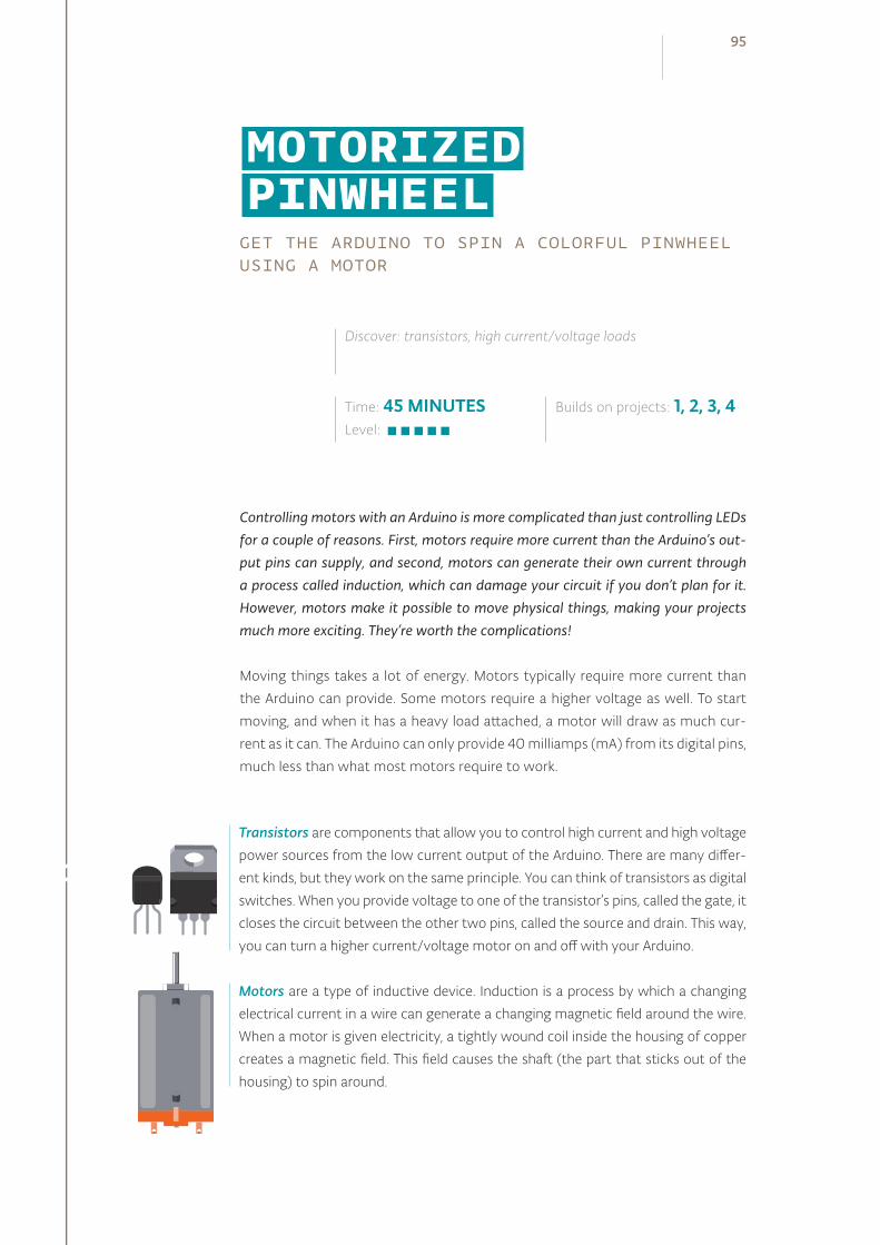
MOTORIZED PINWHEELGET THE ARDUINO TO SPIN A COLORFUL PINWHEEL USING A MOTOR
Controlling motors with an Arduino is more complicated than just controlling LEDs for a couple of reasons. First, motors require more current than the Arduino’s out-put pins can supply, and second, motors can generate their own current through a process called induction, which can damage your circuit if you don’t plan for it. However, motors make it possible to move physical things, making your projects much more exciting. They’re worth the complications!
Moving things takes a lot of energy. Motors typically require more current than
the Arduino can provide. Some motors require a higher voltage as well. To start
moving, and when it has a heavy load attached, a motor will draw as much cur-
rent as it can. The Arduino can only provide 40 milliamps (mA) from its digital pins,
much less than what most motors require to work.
Time: 45 MINUTESLevel:
Discover: transistors, high current/voltage loads
Builds on projects: 1, 2, 3, 4
Transistors are components that allow you to control high current and high voltage
power sources from the low current output of the Arduino. There are many differ-
ent kinds, but they work on the same principle. You can think of transistors as digital
switches. When you provide voltage to one of the transistor’s pins, called the gate, it
closes the circuit between the other two pins, called the source and drain. This way,
you can turn a higher current/voltage motor on and off with your Arduino.
Motors are a type of inductive device. Induction is a process by which a changing
electrical current in a wire can generate a changing magnetic field around the wire.
When a motor is given electricity, a tightly wound coil inside the housing of copper
creates a magnetic field. This field causes the shaft (the part that sticks out of the
housing) to spin around.
95
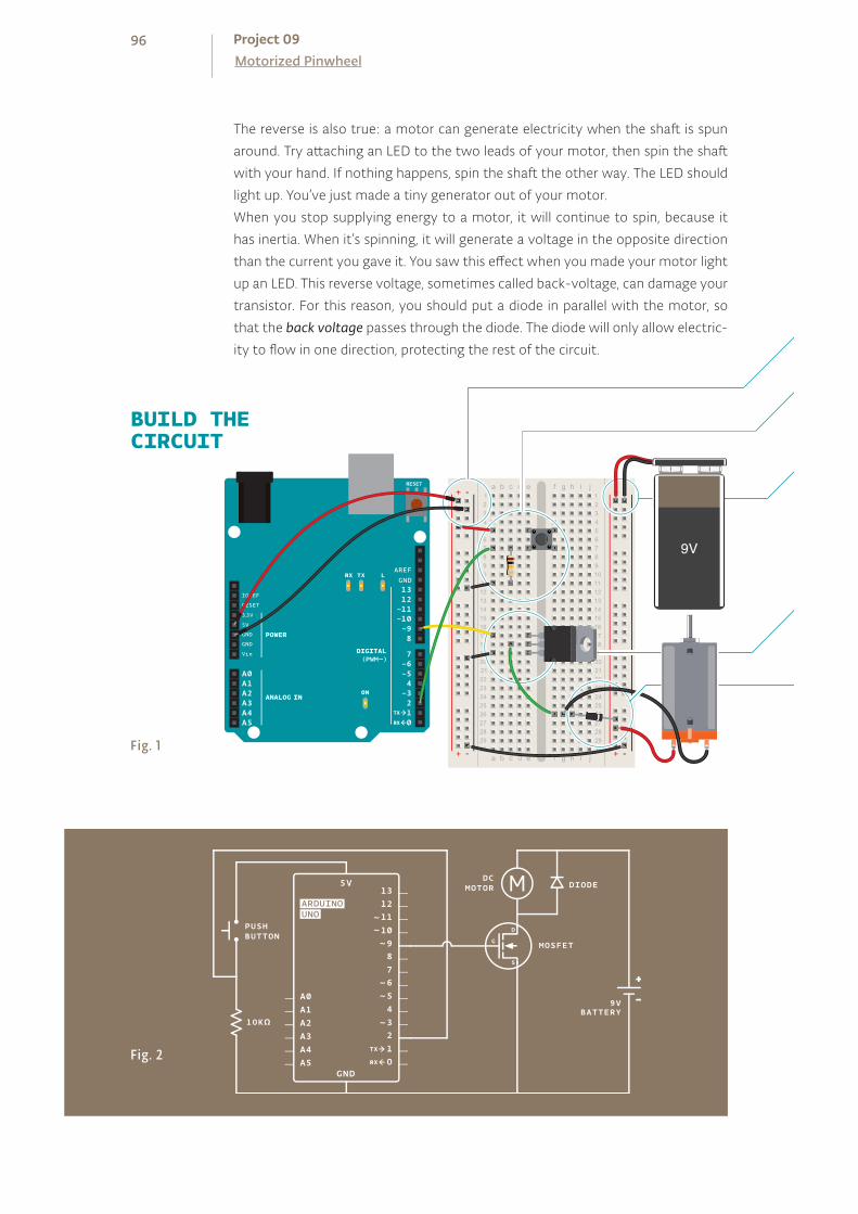
BUILD THECIRCUIT
The reverse is also true: a motor can generate electricity when the shaft is spun
around. Try attaching an LED to the two leads of your motor, then spin the shaft
with your hand. If nothing happens, spin the shaft the other way. The LED should
light up. You’ve just made a tiny generator out of your motor.
When you stop supplying energy to a motor, it will continue to spin, because it
has inertia. When it’s spinning, it will generate a voltage in the opposite direction
than the current you gave it. You saw this effect when you made your motor light
up an LED. This reverse voltage, sometimes called back-voltage, can damage your
transistor. For this reason, you should put a diode in parallel with the motor, so
that the back voltage passes through the diode. The diode will only allow electric-
ity to flow in one direction, protecting the rest of the circuit.
Fig. 2
Fig. 1
96Motorized PinwheelProject 09
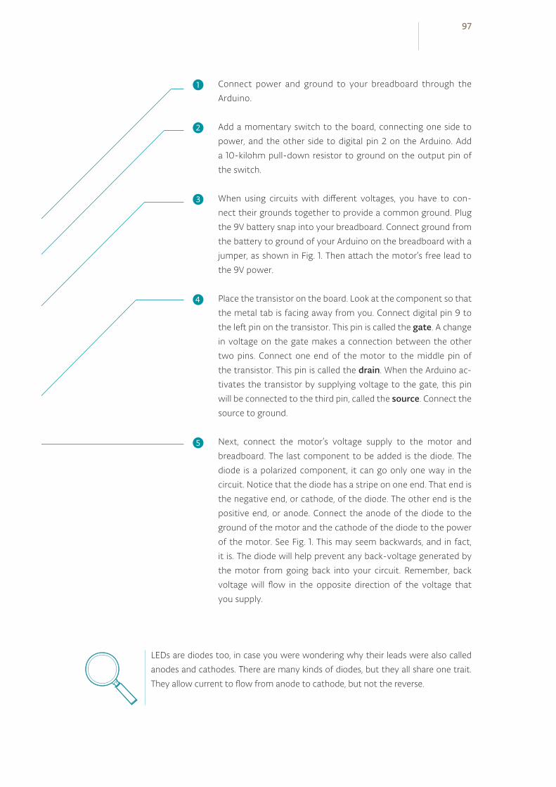
Connect power and ground to your breadboard through the
Arduino.
Add a momentary switch to the board, connecting one side to
power, and the other side to digital pin 2 on the Arduino. Add
a 10-kilohm pull-down resistor to ground on the output pin of
the switch.
When using circuits with different voltages, you have to con-
nect their grounds together to provide a common ground. Plug
the 9V battery snap into your breadboard. Connect ground from
the battery to ground of your Arduino on the breadboard with a
jumper, as shown in Fig. 1. Then attach the motor’s free lead to
the 9V power.
Place the transistor on the board. Look at the component so that
the metal tab is facing away from you. Connect digital pin 9 to
the left pin on the transistor. This pin is called the gate. A change
in voltage on the gate makes a connection between the other
two pins. Connect one end of the motor to the middle pin of
the transistor. This pin is called the drain. When the Arduino ac-
tivates the transistor by supplying voltage to the gate, this pin
will be connected to the third pin, called the source. Connect the
source to ground.
Next, connect the motor’s voltage supply to the motor and
breadboard. The last component to be added is the diode. The
diode is a polarized component, it can go only one way in the
circuit. Notice that the diode has a stripe on one end. That end is
the negative end, or cathode, of the diode. The other end is the
positive end, or anode. Connect the anode of the diode to the
ground of the motor and the cathode of the diode to the power
of the motor. See Fig. 1. This may seem backwards, and in fact,
it is. The diode will help prevent any back-voltage generated by
the motor from going back into your circuit. Remember, back
voltage will flow in the opposite direction of the voltage that
you supply.
LEDs are diodes too, in case you were wondering why their leads were also called
anodes and cathodes. There are many kinds of diodes, but they all share one trait.
They allow current to flow from anode to cathode, but not the reverse.
❶
❷
❸
❹
❺
97
The code is remarkably similar to the code you first used for
turning on an LED. First of all, set up some constants for the
switch and motor pins and a variable named switchState to
hold the value of the switch.
In your setup(), declare the pinMode() of the motor (OUTPUT)
and switch (INPUT) pins.
Your loop() is straightforward. Check the state of the switch-
Pin with digitalRead().
If the switch is pressed, turn the motorPin HIGH. If it is not
pressed, turn the pin LOW. When HIGH, the transistor will acti-
vate, completing the motor circuit. When LOW, the motor will not
spin.
Read the input , pul l the output high i f pressed
Declare the pins’ d irect ion
Name your constants and var iables
THE CODE
Motors have an optimal operating voltage. They will work on as little as 50% of the
rated voltage and as much as 50% over that number. If you vary the voltage, you
can change the speed at which the motor rotates. Don’t vary it too much, though,
or you will burn out your motor.
Motors require special consideration when being controlled by a microcontroller.
Typically the microcontroller cannot provide enough current and/or voltage to
power a motor. Because of this, you use transistors to interface between the two.
It’s also smart to use diodes to prevent damaging your circuit.
98Motorized PinwheelProject 09
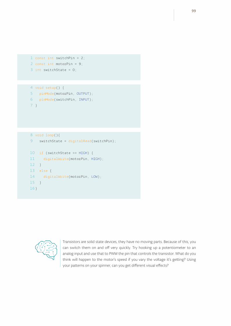
1
2
3
4
5
6
7
8
9
const int switchPin = 2;
const int motorPin = 9;
int switchState = 0;
void setup()
pinMode(motorPin, OUTPUT);
pinMode(switchPin, INPUT);
void loop()
switchState = digitalRead(switchPin);
if (switchState == HIGH)
digitalWrite(motorPin, HIGH);
else
digitalWrite(motorPin, LOW);
Transistors are solid state devices, they have no moving parts. Because of this, you
can switch them on and off very quickly. Try hooking up a potentiometer to an
analog input and use that to PWM the pin that controls the transistor. What do you
think will happen to the motor’s speed if you vary the voltage it’s getting? Using
your patterns on your spinner, can you get different visual effects?
10
11
12
13
14
15
16
99
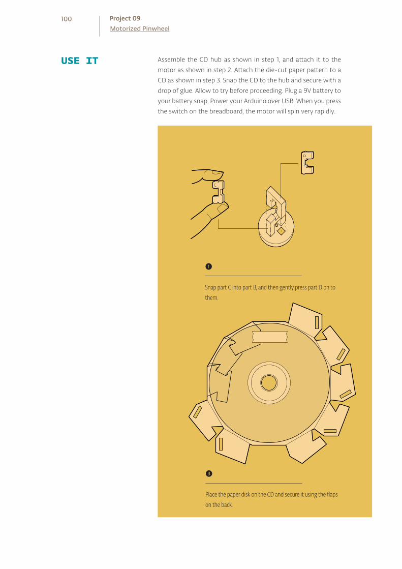
Assemble the CD hub as shown in step 1, and attach it to the
motor as shown in step 2. Attach the die-cut paper pattern to a
CD as shown in step 3. Snap the CD to the hub and secure with a
drop of glue. Allow to try before proceeding. Plug a 9V battery to
your battery snap. Power your Arduino over USB. When you press
the switch on the breadboard, the motor will spin very rapidly.
USE IT
❶
Snap part C into part B, and then gently press part D on to them.
❸
Place the paper disk on the CD and secure it using the flaps on the back.
100Motorized PinwheelProject 09
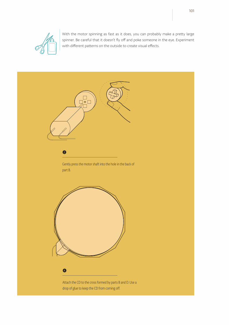
With the motor spinning as fast as it does, you can probably make a pretty large
spinner. Be careful that it doesn’t fly off and poke someone in the eye. Experiment
with different patterns on the outside to create visual effects.
❷
Gently press the motor shaft into the hole in the back of part B.
❹
Attach the CD to the cross formed by parts B and D. Use a drop of glue to keep the CD from coming off.
101
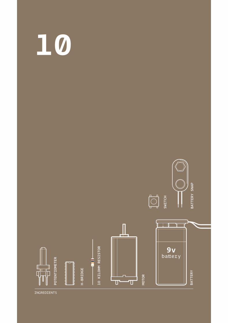
INGREDIENTS
10
MOTOR
BATTERY SNAP
BATTERY
9vbattery
SWITCH
10 KILOHM RESISTOR
H-BRIDGE
POTENTIOMETER

CREATE MOVING IMAGES IN FORWARD AND REVERSE WITH YOUR ARDUINO WHEN YOU CONNECT A MOTOR TO AN H-BRIDGE AND SOME STILL IMAGES
Before the internet, television, even before movies, some of the first moving images were created with a tool called a zoetrope. Zoetropes create the illusion of motion from a group of still images that have small changes in them. They are typically cylinders with slits cut in the side. When the cylinder spins and you look through the slits, your eyes perceive the still images on the other side of the wall to be ani-mated. The slits help keep the images from becoming a big blur, and the speed at which the images appear provide cause the images to appear to move. Originally, these novelties were spun by hand, or with a cranking mechanism.
In this project, you’ll build your own zoetrope that animates a carnivorous plant.
You’ll power the motion with a motor. To make this system even more advanced,
you’ll add a switch that lets you control direction, another to turn it off and on,
and a potentiometer to control the speed.
In the Motorized Pinwheel Project you got a motor to spin in one direction. If you
were to take power and ground on the motor and flip their orientation, the motor
would spin in the opposite direction. It’s not very practical to do that everytime
you want to spin something in a different direction, so you’ll be using a compo-
nent called an H-bridge to reverse the polarity of the motor.
H-bridges are a type of component known as integrated circuits (IC). ICs are
components that hold large circuits in a tiny package. These can help simplify
more complex circuits by placing them in an easily replaceable component. For
example, the H-bridge you’re using in this example has a number of transistors
built in. To build the circuit inside the H-bridge you would probably need another
breadboard.
Time: 30 MINUTESLevel:
Builds on projects: 1, 2, 3, 4, 9
Discover: H-bridges
ZOETROPE
103
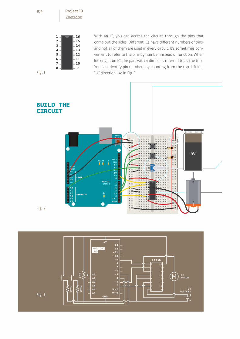
With an IC, you can access the circuits through the pins that
come out the sides. Different ICs have different numbers of pins,
and not all of them are used in every circuit. It’s sometimes con-
venient to refer to the pins by number instead of function. When
looking at an IC, the part with a dimple is referred to as the top .
You can identify pin numbers by counting from the top-left in a
“U” direction like in Fig. 1.
12345678
161514131211109
BUILD THECIRCUIT
Fig. 2
Fig. 3
Fig. 1
+ - + -
+ -+ -
9V
104ZoetropeProject 10
Connect power and ground from one side of your breadboard
to the Arduino.
Add 2 momentary switches to the breadboard, connecting one
side of each to power. Add a 10Kohm pull-down resistor in
series with ground on the output pin of both switches.
The switch on pin 4 will control direction, the switch on pin 5
will turn the motor on and off.
Connect the potentiometer to the breadboard. Wire 5V to one
side and ground to the other. Attach the center pin to analog
input 0 on the Arduino. This will be used to control the speed
of the motor.
Place the H-bridge on your breadboard so it straddles the
center (see Fig. 2 for detail of placement). Connect pin 1 of the
H-bridge to digital pin 9 on the Arduino. This is the enable pin
on the H-bridge. When it receives 5V, it turns the motor on,
when it receives 0V, it turns the motor off. You will use this pin
to PWM the H-bridge, and adjust the speed of the motor.
Connect pin 2 on the H-bridge to digital pin 3 on the Arduino.
Connect pin 7 to digital pin 2. These are the pins you will use
to communicate with the H-bridge, telling it which direction to
spin. If pin 3 is LOW and pin 2 is HIGH, the motor will spin in one
direction. If pin 2 is LOW and pin 3 is HIGH, the motor will spin
in the opposite direction. If both the pins are HIGH or LOW at
the same time, the motor will stop spinning.
The H-bridge get its power from pin 16, plug that into 5V. Pins 4
and 5 both go to ground.
Attach your motor to pins 3 and 6 on the H-bridge. These two
pins will switch on and off depending on the signals you send
to pins 2 and 7.
Plug the battery connector (without the battery attached!)
to the other power rails on your breadboard. Connect ground
from your Arduino to the battery’s ground. Connect pin 8 from
the H-bridge to the battery power. This is the pin that the
H-bridge powers the motor from. Make sure you do not have
your 9V and 5V power lines connected. They must be separate,
only ground should be connected between the two.
❶
❷
❸
❹
❺
❻
❼
❽
105
Create constants for the output and input pins.
Use variables to hold the values from your inputs. You’ll be doing
state change detection for both switches, comparing the state
from one loop to the next, similar to the Hourglass Project. So,
in addition to storing the current state, you’ll need to record the
previous state of each switch.
motorDirection keeps track of which direction the motor is
spinning, and motorPower keeps track of whether the motor is
spinning or not.
In setup(), set the direction of each input and output pin.
Turn the enable pin LOW to start, so the motor isn’t spinning right
away.
In your loop(), read the state of the On/Off switch and store it
in the onOffSwitchState variable.
THE CODE
Name your constants
Create var iables for remem-bering program state
Create var iables for motor control
Declare the digita l p ins as inputs and outputs
Turn the motor off
Read sensor information
106ZoetropeProject 10
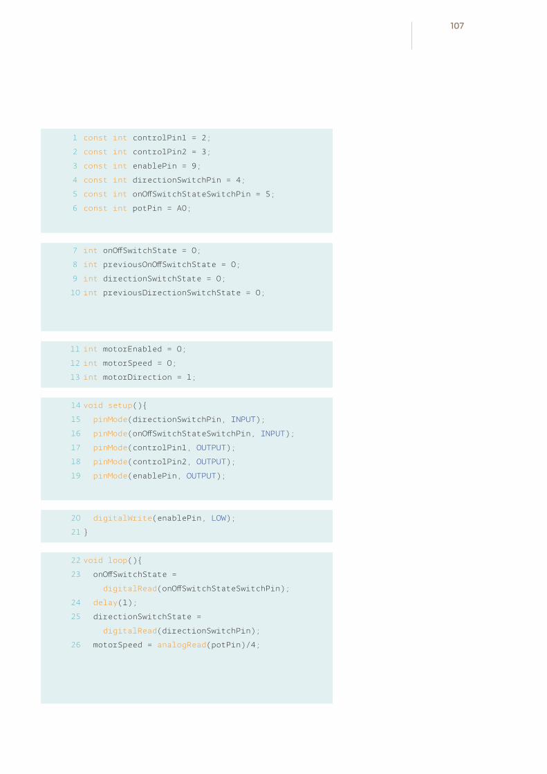
1
2
3
4
5
6
7
8
9
10
const int controlPin1 = 2;
const int controlPin2 = 3;
const int enablePin = 9;
const int directionSwitchPin = 4;
const int onOffSwitchStateSwitchPin = 5;
const int potPin = A0;
int onOffSwitchState = 0;
int previousOnOffSwitchState = 0;
int directionSwitchState = 0;
int previousDirectionSwitchState = 0;
int motorEnabled = 0;
int motorSpeed = 0;
int motorDirection = 1;
void setup()
pinMode(directionSwitchPin, INPUT);
pinMode(onOffSwitchStateSwitchPin, INPUT);
pinMode(controlPin1, OUTPUT);
pinMode(controlPin2, OUTPUT);
pinMode(enablePin, OUTPUT);
digitalWrite(enablePin, LOW);
void loop()
onOffSwitchState =
digitalRead(onOffSwitchStateSwitchPin);
delay(1);
directionSwitchState =
digitalRead(directionSwitchPin);
motorSpeed = analogRead(potPin)/4;
11
12
13
14
15
16
17
18
19
20
21
22
23
24
25
26
107
If there is a difference between the current switch state and the
previous, and the switch is currently HIGH, set the motorPower
variable to 1. If it is LOW, set the variable to 0.
Read the values of the direction switch and potentiometer. Store
the values in their respective variables.
Check to see if the direction switch is currently in a different
position than it was previously.If it is different, change the motor
direction variable. There are only 2 ways for the motor to spin,
so you’ll want to alternate the variable between two states. One
way to accomplish this is by using the inversion operator like so:
motorDirection =!motorDirection.
The motorDirection variable determines which direction the
motor is turning. To set the direction, you set the control pins
setting one HIGH and the other LOW. When motorDirection
changes, reverse the states of the control pins.
If the direction switch gets pressed, you’ll want to spin the
motor in the other direction by reversing the state of the
controlPins.
If the motorEnabled variable is 1, set the speed of the motor using
analogWrite() to PWM the enable pin. If motorEnabled is
0, then turn the motor off by setting the analogWrite value
to 0.
Before exiting the loop(), save the current state of the switches
as the previous state for the next run through the program.
Check i f on/off sensor has changed
Check to see i f the direct ion has changed
Change the pins to turn the motor in the proper direct ion
PWM the motor i f i t is enabled
Save the current states for the next loop()
108ZoetropeProject 10

27
28
29
30
31
if(onOffSwitchState != previousOnOffSwitchState)
if(onOffSwitchState == HIGH)
motorEnabled = !motorEnabled;
if (directionSwitchState !=
previousDirectionSwitchState)
if (directionSwitchState == HIGH)
motorDirection = !motorDirection;
if (motorDirection == 1)
digitalWrite(controlPin1, HIGH);
digitalWrite(controlPin2, LOW);
else
digitalWrite(controlPin1, LOW);
digitalWrite(controlPin2, HIGH);
if (motorEnabled == 1)
analogWrite(enablePin, motorSpeed);
else
analogWrite(enablePin, 0);
previousDirectionSwitchState =
directionSwitchState;
previousOnOffSwitchState = onOffSwitchState;
32
33
34
35
36
37
38
39
40
41
42
43
44
45
46
47
48
49
50
51
52
53
109

USE IT Plug your Arduino into your computer. Attach the battery to the
connector. When you press the On/Off switch, the motor should
start spinning. If you turn the potentiometer, it should speed up
and slow down. Pressing the On/Off button another time will
stop the motor. Try pressing the direction button and verify the
motor spins both ways. Also, if you turn the knob on the pot, you
should see the motor speed up or slow down depending on the
value it is sending.
Once you’ve verified that the circuit works as expected, disconnect the battery and USB from the circuit.
❶
Secure the CD onto the wooden base. Add a drop of glue to make sure it doesn’t spin loose when the motor starts.
❷
Use the tabs to close the cutout, forming a circle.
110ZoetropeProject 10
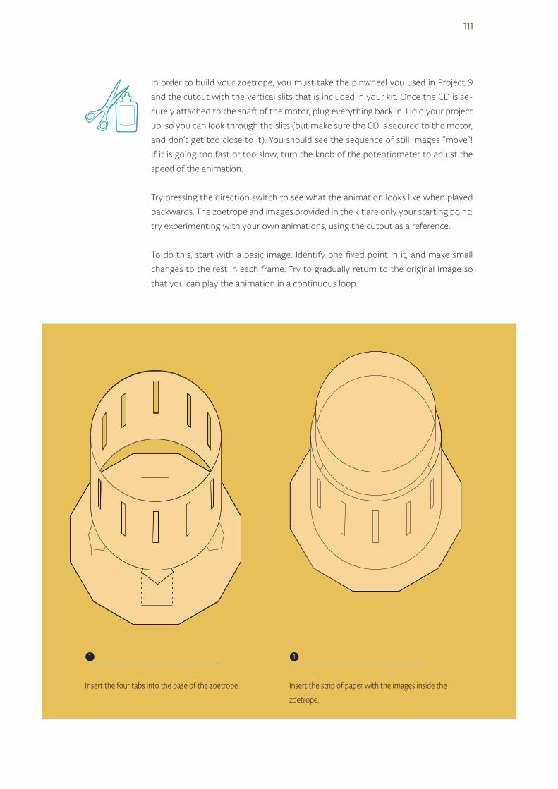
In order to build your zoetrope, you must take the pinwheel you used in Project 9
and the cutout with the vertical slits that is included in your kit. Once the CD is se-
curely attached to the shaft of the motor, plug everything back in. Hold your project
up, so you can look through the slits (but make sure the CD is secured to the motor,
and don’t get too close to it). You should see the sequence of still images “move”!
If it is going too fast or too slow, turn the knob of the potentiometer to adjust the
speed of the animation.
Try pressing the direction switch to see what the animation looks like when played
backwards. The zoetrope and images provided in the kit are only your starting point:
try experimenting with your own animations, using the cutout as a reference.
To do this, start with a basic image. Identify one fixed point in it, and make small
changes to the rest in each frame. Try to gradually return to the original image so
that you can play the animation in a continuous loop.
❶
Insert the four tabs into the base of the zoetrope.
❶
Insert the strip of paper with the images inside the zoetrope.
111
Zoetropes work because of a phenomena called “persistence of vision”, sometimes
abbreviated to POV. POV describes the illusion of motion that is created when our
eyes observe still images with minor variations in rapid succession. If you search
online for “POV display”, you’ll find many projects made by people that leverage this
effect, often with LEDs and an Arduino.
Make a base to support the motor. A small cardboard box with a hole cut in it could
work as a base, leaving your hands free to play with the switches and knob. This will
make it easier to show off your work to everyone.
With a little work, you can get your zoetrope working in low light situations as well.
Hook up an LED and resistor to one of your free digital output pins. Also add a sec-
ond potentiometer, and connect it to an analog input. Position the light so it shines
on the images. Using the analog input to time the flashes of the LED, try and time it
so the light flashes when the slit is in front of your eyes. This could take some fiddling
with the knobs, but the resulting effect is really spectacular!
112ZoetropeProject 10


INGREDIENTS
1110 KILOHM RESISTOR
220 OHM RESISTOR
SWITCH
POTENTIOMETER
LCD SCREEN
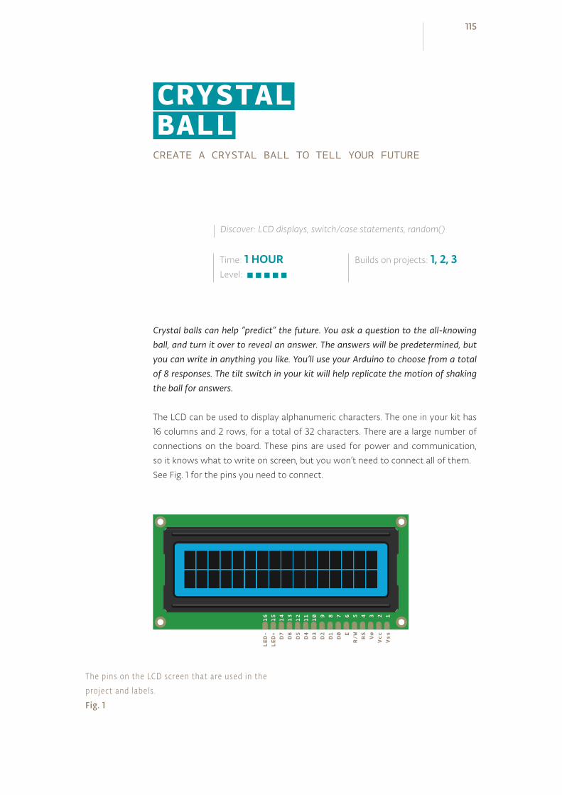
CREATE A CRYSTAL BALL TO TELL YOUR FUTURE
Crystal balls can help “predict” the future. You ask a question to the all-knowing ball, and turn it over to reveal an answer. The answers will be predetermined, but you can write in anything you like. You’ll use your Arduino to choose from a total of 8 responses. The tilt switch in your kit will help replicate the motion of shaking the ball for answers.
The LCD can be used to display alphanumeric characters. The one in your kit has
16 columns and 2 rows, for a total of 32 characters. There are a large number of
connections on the board. These pins are used for power and communication,
so it knows what to write on screen, but you won’t need to connect all of them.
See Fig. 1 for the pins you need to connect.
Time: 1 HOURLevel:
Builds on projects: 1, 2, 3
Discover: LCD displays, switch/case statements, random()
CRYSTAL BALL
D4
D3
D2
D1
D0 E
R/W
RS
V0
Vcc
Vss
D6
D5
D7
LED-
LED+
11
10 9 8 7 6 5 4 3 2 1
13
12
14
16
15
The pins on the LCD screen that are used in the project and labels .Fig. 1
115

BUILD THECIRCUIT
+ - + -
+ -+ -
Fig. 2
Fig. 3
In this schematic the LCD pins arrangement does not match the physical order depicted in Fig . 2 .In a schematic , the pins are rearranged by logical grouping to make the schematic as c lear as pos-s ible . This is a l i tt le confusing to newcomers unti l you get used to it .
116Crystal BallProject 11
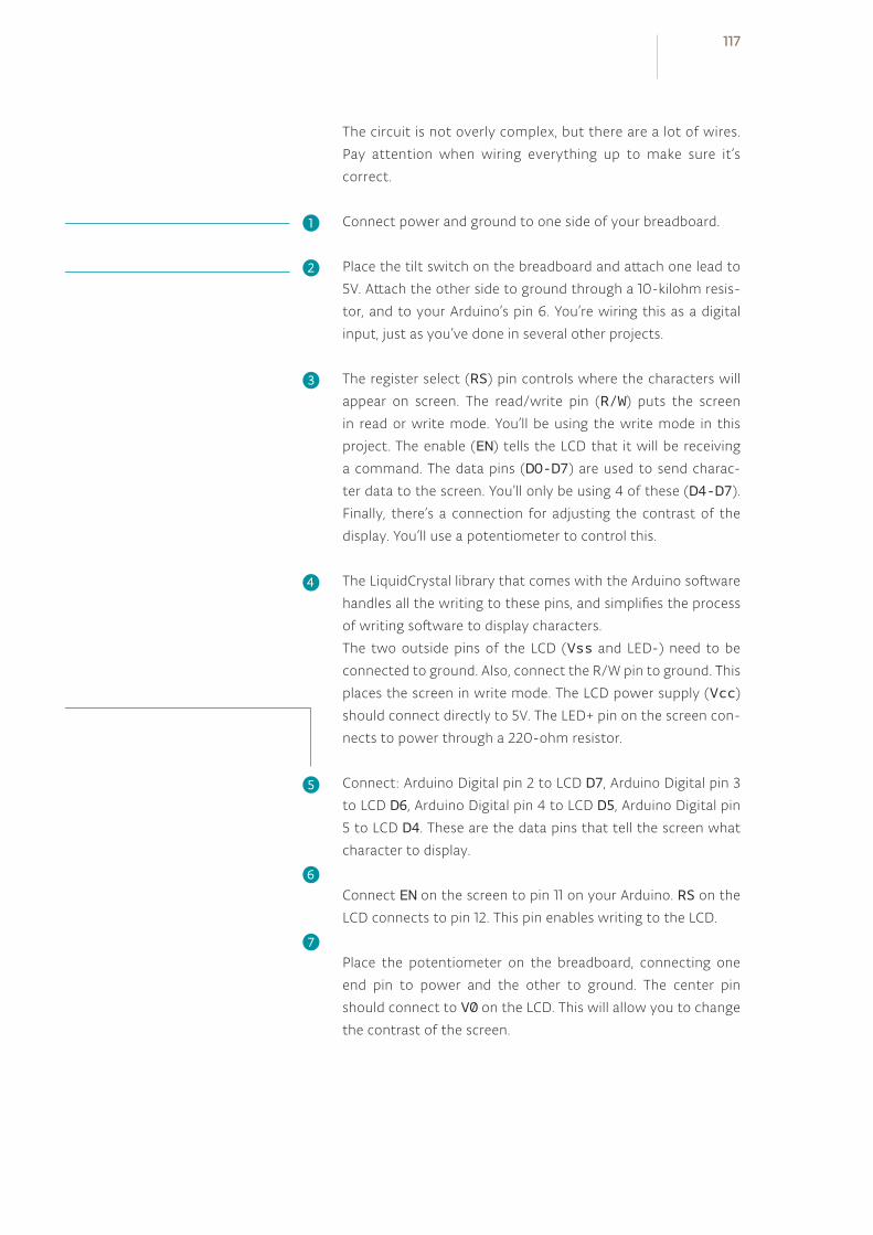
The circuit is not overly complex, but there are a lot of wires.
Pay attention when wiring everything up to make sure it’s
correct.
Connect power and ground to one side of your breadboard.
Place the tilt switch on the breadboard and attach one lead to
5V. Attach the other side to ground through a 10-kilohm resis-
tor, and to your Arduino’s pin 6. You’re wiring this as a digital
input, just as you’ve done in several other projects.
The register select (RS) pin controls where the characters will
appear on screen. The read/write pin (R/W) puts the screen
in read or write mode. You’ll be using the write mode in this
project. The enable (EN) tells the LCD that it will be receiving
a command. The data pins (D0-D7) are used to send charac-
ter data to the screen. You’ll only be using 4 of these (D4-D7).
Finally, there’s a connection for adjusting the contrast of the
display. You’ll use a potentiometer to control this.
The LiquidCrystal library that comes with the Arduino software
handles all the writing to these pins, and simplifies the process
of writing software to display characters.
The two outside pins of the LCD (Vss and LED-) need to be
connected to ground. Also, connect the R/W pin to ground. This
places the screen in write mode. The LCD power supply (Vcc)
should connect directly to 5V. The LED+ pin on the screen con-
nects to power through a 220-ohm resistor.
Connect: Arduino Digital pin 2 to LCD D7, Arduino Digital pin 3
to LCD D6, Arduino Digital pin 4 to LCD D5, Arduino Digital pin
5 to LCD D4. These are the data pins that tell the screen what
character to display.
Connect EN on the screen to pin 11 on your Arduino. RS on the
LCD connects to pin 12. This pin enables writing to the LCD.
Place the potentiometer on the breadboard, connecting one
end pin to power and the other to ground. The center pin
should connect to V0 on the LCD. This will allow you to change
the contrast of the screen.
❶❷
❸
❹
❺
❻
❼
117

First, you’ll need to import the LiquidCrystal library.
Next, you’ll initialize the library, somewhat similar to the way you
did with the Servo library, telling it what pins it will be using to
communicate.
Now that you’ve set up the library, it’s time to create some
variables and constants. Create a constant to hold the pin of
the switch pin, a variable for the current state of the switch, a
variable for the previous state of the switch, and one more to
choose which reply the screen will show.
Set up the switch pin as an input with pinMode() in your
setup(). Start the LCD library, and tell it how large the screen is.
Now it’s time to write a small introductory screen welcoming you
to the 8-ball. The print() function writes to the LCD screen.
You’re going to write the words “Ask the” on the top line of the
screen. The cursor is automatically at the beginning of the top line.
In order to write to the next line, you’ll have to tell the screen
where to move the cursor. The coordinates of the first column on
the second line are 0,1 (recall that computers are zero indexed.
0,0 is the first column of the first row). Use the function lcd.
setCursor() to move the cursor to the proper place, and tell
it to write “Crystal ball!”.
Now, when you start the program, it will say “Ask the Crystal ball!”
on your screen.
In the loop(), you’re going to check the switch first, and put the
value in the switchState variable.
Use an if() statement to determine if the switch is in a different
position than it was previously. If it is different than it was before,
and it is currently LOW, then it’s time to choose a random reply.
The random() function returns a number based on the
argument you provide it. To start, you’ll have a total number
of 8 different responses for the ball. Whenever the statement
random(8) is called, it will give a number between 0-7. Store that
number in your reply variable.
Set up the L iquidCrystal l ibrary
Pr int your f i rst l ine
Move the cursor
Choose a random anwser
118Crystal BallProject 11
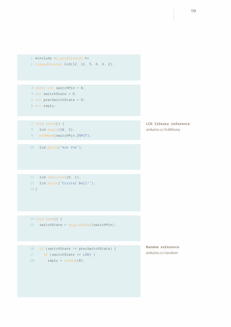
1
2
#include <LiquidCrystal.h>
LiquidCrystal lcd(12, 11, 5, 4, 3, 2);
const int switchPin = 6;
int switchState = 0;
int prevSwitchState = 0;
int reply;
void setup()
lcd.begin(16, 2);
pinMode(switchPin,INPUT);
lcd.print(“Ask the”);
lcd.setCursor(0, 1);
lcd.print(“Crystal Ball!”);
void loop()
switchState = digitalRead(switchPin);
if (switchState != prevSwitchState)
if (switchState == LOW)
reply = random(8);
3
4
5
6
7
8
9
10
11
12
13
14
15
16
17
18
LCD library reference
arduino.cc/lcdlibrary
Random reference
arduino.cc/random
119

Clear the screen with the function lcd.clear(). This also
moves the cursor back to location 0,0; the first column in the
first row of the LCD. Print out the line “ The ball says:” and move
the cursor for the output.
The switch() statement executes different pieces of code
depending on the value you give it. Each of these different pieces
of code is called a case. switch() checks the value of the
variable reply; whatever value reply holds will determine what
named case statement is executed.
Inside the case statements, the code will be the same, but the
messages will be different. For example, in case 0 the code
says lcd.print (“Yes”). After the lcd.print() function,
there’s another command: break. It tells the Arduino where the
end of the case is. When it hits break, it skips to the end of the
switch statement. You’ll be creating a total of 8 case statements
to start out. Four of the responses will be positive, 2 will be
negative, and the final 2 will ask you to try again.
The last thing to do in your loop() is to assign switchState’s
value to the variable prevSwitchState. This enables you to
track changes in the switch the next time the loop runs.
Predict the future
120Crystal BallProject 11
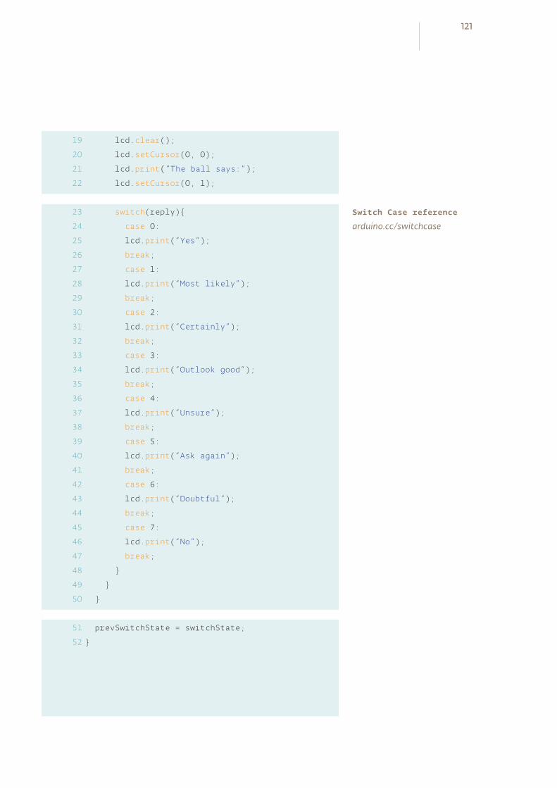
19
20
21
22
lcd.clear();
lcd.setCursor(0, 0);
lcd.print(“The ball says:”);
lcd.setCursor(0, 1);
switch(reply)
case 0:
lcd.print(“Yes”);
break;
case 1:
lcd.print(“Most likely”);
break;
case 2:
lcd.print(“Certainly”);
break;
case 3:
lcd.print(“Outlook good”);
break;
case 4:
lcd.print(“Unsure”);
break;
case 5:
lcd.print(“Ask again”);
break;
case 6:
lcd.print(“Doubtful”);
break;
case 7:
lcd.print(“No”);
break;
prevSwitchState = switchState;
23
24
25
26
27
28
29
30
31
32
33
34
35
36
37
38
39
40
41
42
43
44
45
46
47
48
49
50
51
52
Switch Case reference
arduino.cc/switchcase
121

USE IT To use the magic ball, power the Arduino. Check the screen to
make sure it says “Ask the Crystal ball!” If you can’t see the char-
acters, try turning the potentiometer. It will adjust the contrast
of the screen.
Ask a question of your crystal ball, and try tilting the switch up-
side down and back again. You should get an answer to your
question. If the answer doesn’t suit you, ask again.
LCDs work by changing the electrical properties of a liquid sandwiched between
polarized glass. The glass only allows certain kinds of light to pass through. When
the liquid between the glass is charged, it starts to form into a semi-solid state. This
new state runs in a different direction than the polarized glass, blocking light from
passing through, thus creating the characters you see on the screen.
Try adding your own sayings to the print() statements, but be mindful of the
fact that there are only 16 characters to use per line. You can also try adding more
responses. Make sure when you add additional switch cases, you adjust the number
of options that will randomly populate the reply variable.
The functions covered here for changing the LCD screen’s text are fairly simple.
Once you have a handle on how it works, look at some of the other functions the
library has. Try getting text to scroll, or continually update. To find out more about
how the LiquidCrystal library works, visit: arduino.cc/lcd
An LCD display enables you to show text on a screen, using the LiquidCrystal library. With a switch...case statements control the flow of programs by comparing a variable to specified values.
122Crystal BallProject 11

INGREDIENTS
10 KILO OHM RESISTOR
220 OHM RESISTOR
1 MEGOHM RESISTOR
SWITCH
LED
12
PIEZO
SERVO MOTOR
100uF CAPACITOR
MALE HEADER PIN (3 pins)

MAKE YOUR OWN SECRET LOCKING MECHANISM TO KEEP UNWANTED GUESTS OUT OF YOUR SPACE!
The piezo you used for playing back sounds in the theremin and keyboard pro-jects can also be used as an input device. When plugged into 5V, the sensor can detect vibrations that can be read by the Arduino’s analog inputs. You’ll need to plug in a high value resistor (like 1-megohm) as the reference to ground for this to work well.
When the piezo is pressed flat against a solid surface that can vibrate, like a wood-
en table top, your Arduino can sense how intense a knock is. Using this informa-
tion you can check to see if a number of knocks fall in an acceptable range. In code
you can track the number of knocks and see if they match your settings.
A switch will let you lock the motor in place. Some LEDs will give you status: a red
LED will indicate the box is locked, a green LED will indicate the box is unlocked,
and a yellow LED lets you know if a valid knock has been received.
You’ll also be writing your own function that will let you know if a knock is too loud
or too soft. Writing your own function helps save time programming by reusing
code instead of writing it out many times. Functions can take arguments and
return values. In this case, you’ll give a function the volume of the knock. If it is in
the right range, you’ll increment a variable.
It’s possible to build the circuit by itself, but it’s much more fun if you use this as
a tool to lock something. If you have a wooden or a cardboard box you can cut
holes into, use the servo motor to open and close a latch, keeping people from
getting at your stuff.
Time: 1 HOURLevel:
Builds on projects: 1, 2, 3, 4, 5
Discover: input with a piezo, writing your own functions
KNOCK LOCK
125
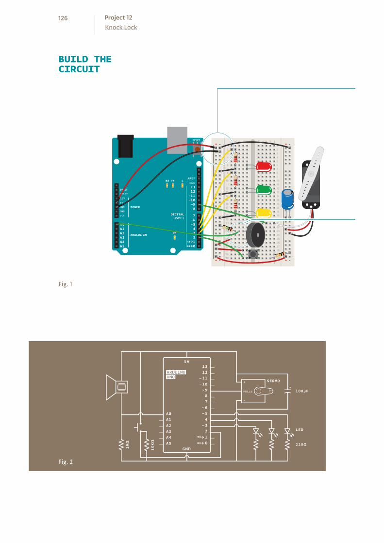
BUILD THECIRCUIT
Fig. 1
Fig. 2
+ - + -
+ -+ -
126Knock LockProject 12
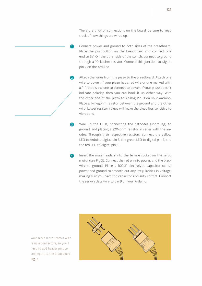
There are a lot of connections on the board, be sure to keep
track of how things are wired up.
Connect power and ground to both sides of the breadboard.
Place the pushbutton on the breadboard and connect one
end to 5V. On the other side of the switch, connect to ground
through a 10-kilohm resistor. Connect this junction to digital
pin 2 on the Arduino.
Attach the wires from the piezo to the breadboard. Attach one
wire to power. If your piezo has a red wire or one marked with
a “+”, that is the one to connect to power. If your piezo doesn’t
indicate polarity, then you can hook it up either way. Wire
the other end of the piezo to Analog Pin 0 on your Arduino.
Place a 1-megohm resistor between the ground and the other
wire. Lower resistor values will make the piezo less sensitive to
vibrations.
Wire up the LEDs, connecting the cathodes (short leg) to
ground, and placing a 220-ohm resistor in series with the an-
odes. Through their respective resistors, connect the yellow
LED to Arduino digital pin 3, the green LED to digital pin 4, and
the red LED to digital pin 5.
Insert the male headers into the female socket on the servo
motor (see Fig.3). Connect the red wire to power, and the black
wire to ground. Place a 100uF electrolytic capacitor across
power and ground to smooth out any irregularities in voltage,
making sure you have the capacitor’s polarity correct. Connect
the servo’s data wire to pin 9 on your Arduino.
❶
❷
❸
❹
Your servo motor comes with female connectors , so you’ l l need to add header pins to connect i t to the breadboard.Fig. 3
127
Just as in the earlier Mood Cue Project, you’ll need to import the
Servo library and create an instance to use the motor.
Create constants to name your inputs and outputs.
Create variables to hold the values from your switch and piezo.
Set up some constants to use as thresholds for the knock
maximum and minimum levels.
The locked variable will let you know if the lock is enganged or
not. A boolean is a data type that can only be true (1) or false
(0). You should start with the mechanism unlocked.
The last global variable will hold the number of valid knocks you
have received.
In your setup(), attach the servo to pin 9.
Set the LED pins as outputs and the switch pins as inputs.
Initialize serial communication with the computer so you can
monitor the knock volume, what the current state of the lock is,
and how many more knocks you have to go.
Turn on the green LED, move the servo to the unlocked position,
and print the current status to the serial monitor indicating the
circuit is in the unlocked position.
In the loop(), you’ll first check to see if the box is locked or not.
This will determine what happens in the rest of the program. If it
is locked, read the switch value.
THE CODE
Servo l ibrary
Useful constants
Var iables to hold switch and piezo values
Knock tresholds
Var iables for lock state and number of knocks
Sett ing the direct ion of the digita l p ins and in it ia l iz ing servo object and ser ia l port
Unlock
Checking the switch
128Knock LockProject 12
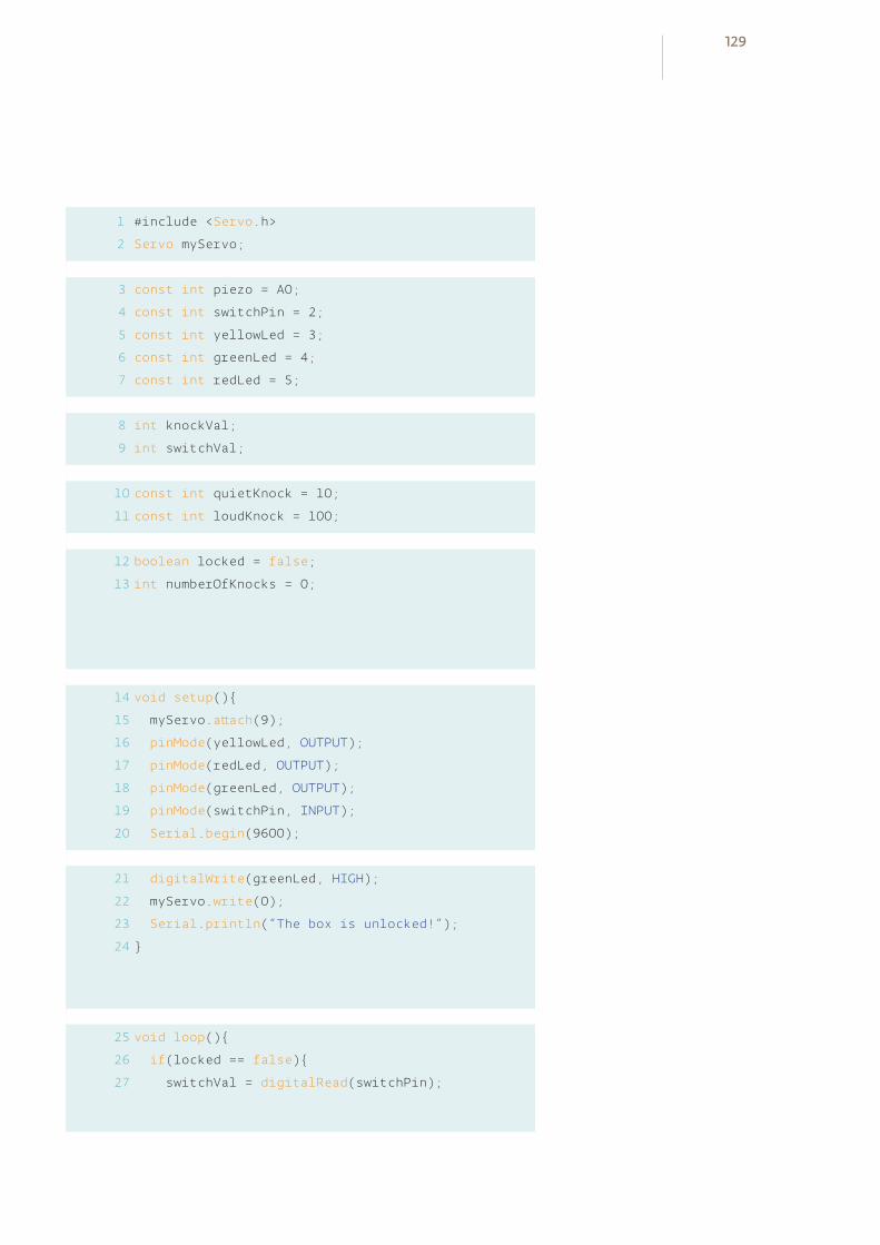
1
2
#include <Servo.h>
Servo myServo;
const int piezo = A0;
const int switchPin = 2;
const int yellowLed = 3;
const int greenLed = 4;
const int redLed = 5;
int knockVal;
int switchVal;
const int quietKnock = 10;
const int loudKnock = 100;
boolean locked = false;
int numberOfKnocks = 0;
void setup()
myServo.attach(9);
pinMode(yellowLed, OUTPUT);
pinMode(redLed, OUTPUT);
pinMode(greenLed, OUTPUT);
pinMode(switchPin, INPUT);
Serial.begin(9600);
digitalWrite(greenLed, HIGH);
myServo.write(0);
Serial.println(“The box is unlocked!”);
void loop()
if(locked == false)
switchVal = digitalRead(switchPin);
3
4
5
6
7
8
9
10
11
12
13
14
15
16
17
18
19
20
21
22
23
24
25
26
27
129
If the switch is closed (you’re pressing it), change the locked
variable to true, indicating the lock is engaged. Turn the green
LED off, and the red LED on. If you don’t have the serial monitor
on, this is helpful visual feedback to let you know the status of
the lock. Move the servo into the lock position, and print out a
message to the serial monitor indicating the box is now locked.
Add a delay so the lock has plenty of time to move into place.
If the locked variable is true, and the lock is engaged, read the
value of the vibration of the piezo and store it in knockVal.
The next statement checks to see if you have fewer than three
valid knocks, and there is some vibration on the sensor. If these
are both true, check to see if this current knock is valid or not and
increment the numberOfKnocks variable. This is where you’ll
call your custom function checkForKnocks(). You’ll write the
function once you’re finished with the loop(), but you already
know you’re going to be asking it if this is a valid knock, so pass
the knockVal along as an argument. After checking your function,
print out the number of knock still needed.
Check to see if you have three or more valid knocks. If this is
true, change the locked variable to false, and move the servo to
the unlocked position. Wait for a few milliseconds to let it start
moving, and change the status of the green and red LEDs. Print
out a status message to the serial monitor, indicating the box is
unlocked.
Close up the else statement and the loop() with a pair of
curly brackets.
Now it’s time to write the function checkForKnock(). When
you’re writing functions of your own, you need to indicate if it is going
to return a value or not. If it is not going to return a value, you declare
it as type void, similar to the loop() and setup() functions. If it
is going to return a value, you must declare what kind (int, long,
float, etc.). In this case, you’re checking to see if a knock is valid
(true) or not (false). Declare the function as type boolean.
Lock
Checking the knock sensor
Counting only val id knocks
Unlock
Defining a funct ion to check knock val id ity
130Knock LockProject 12

28
29
30
31
32
33
34
35
36
if(switchVal == HIGH)
locked = true;
digitalWrite(greenLed,LOW);
digitalWrite(redLed,HIGH);
myServo.write(90);
Serial.println(“The box is locked!”);
delay (1000);
if(locked == true)
knockVal = analogRead(piezo);
if(numberOfKnocks < 3 && knockVal > 0)
if(checkForKnock(knockVal) == true)
numberOfKnocks++;
Serial.print(3-numberOfKnocks);
Serial.println(“ more knocks to go”);
if(numberOfKnocks >= 3)
locked = false;
myServo.write(0);
delay(20);
digitalWrite(greenLed,HIGH);
digitalWrite(redLed,LOW);
Serial.println(“The box is unlocked!”);
boolean checkForKnock(int value)
39
40
41
42
43
44
45
46
47
48
49
50
51
52
53
54
55
56
37
38
131
This particular function will be checking a number (your variable
knockVal) to see if it is valid or not. To pass this variable along
to the function, you create a named parameter when you declare
the function.
In your function, whenever you refer to value it will use whatever
number it receives as an argument in the main program. At this
point value will be set to whatever knockVal is.
Check to see if value is greater than your quiet knock, and less
than your loud knock.
If the value falls between those two values it’s a valid knock. Blink
the yellow LED once and print the value of the knock to the serial
monitor.
To let the main program know what the outcome of the
comparison is, you use the command return. You use the
return command, which also terminates the function: once it
executes, you return to the main program.
If value is either too quiet or too loud, print it out to the serial
monitor and return false.
Close up your function with one more bracket .
When you first plug in the circuit to your Arduino, open the
serial monitor. You should see the green LED turn on, and the
servo will move to the unlocked position.
The serial monitor should print out “The box is unlocked!”.
You’ll probably hear the piezo make a small “click” when it first
gets power.
Try knocking soft and hard to see what sort of intensity knock
triggers your function. You’ll know it’s working when the yel-
USE IT
Check val id ity of knock
Indicat ing knock is val id
Function returns true
Indicat ing inval id knock; funct ion returns fa lse
132Knock LockProject 12
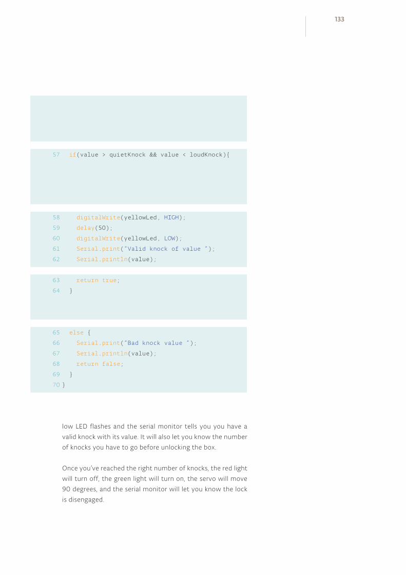
if(value > quietKnock && value < loudKnock)
digitalWrite(yellowLed, HIGH);
delay(50);
digitalWrite(yellowLed, LOW);
Serial.print(“Valid knock of value “);
Serial.println(value);
return true;
else
Serial.print(“Bad knock value “);
Serial.println(value);
return false;
57
58
59
60
61
62
63
64
65
66
67
68
69
70
low LED flashes and the serial monitor tells you you have a
valid knock with its value. It will also let you know the number
of knocks you have to go before unlocking the box.
Once you’ve reached the right number of knocks, the red light
will turn off, the green light will turn on, the servo will move
90 degrees, and the serial monitor will let you know the lock
is disengaged.
133
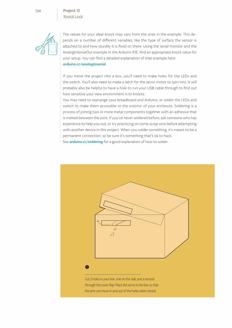
The values for your ideal knock may vary from the ones in the example. This de-
pends on a number of different variables, like the type of surface the sensor is
attached to and how sturdily it is fixed on there. Using the serial monitor and the
AnalogInSerialOut example in the Arduino IDE, find an appropriate knock value for
your setup. You can find a detailed explanation of that example here:
arduino.cc/analogtoserial
If you move the project into a box, you’ll need to make holes for the LEDs and
the switch. You’ll also need to make a latch for the servo motor to spin into. It will
probably also be helpful to have a hole to run your USB cable through to find out
how sensitive your new environment is to knocks.
You may need to rearrange your breadboard and Arduino, or solder the LEDs and
switch to make them accessible to the exterior of your enclosure. Soldering is a
process of joining two or more metal components together with an adhesive that
is melted between the joint. If you’ve never soldered before, ask someone who has
experience to help you out, or try practicing on some scrap wire before attempting
with another device in this project. When you solder something, it’s meant to be a
permanent connection, so be sure it’s something that’s ok to hack.
See arduino.cc/soldering for a good explanation of how to solder.
❶
Cut 2 holes in your box: one on the side, and a second through the cover flap. Place the servo in the box so that the arm can move in and out of the holes when closed.
134Knock LockProject 12

Writing your own functions not only allows you to control the flow of your code more
easily, it also helps keep it readable as your projects become larger and larger. Over
time, as you write more code, you may find you have a large number of functions you
can re-use in different projects, making the process quicker and unique to your style
of programming.
Piezo elements can be used as inputs when wired up as voltage dividers with a high value resistor. Designing a function is an easy way to write code that can be reused for specific tasks.
This example simply counts the right number of knocks, no matter how long it takes.
You can start to make a more complex example by creating a timer with millis().
Use the timer to identify if the knocks happen in a specific period of time. Look back
at the Digital Hourglass Project for an example of how a timer works. You aren’t lim-
ited to simply finding knocks in a specific range. You can look for complex patterns of
knocks based on the amount of vibration and timing together. There are a number
of examples online that talk about how to do this, search for “Arduino knock lock” to
discover more examples of this type of project.
❷
Secure the servo in place with some tape, again making sure the arm can easily rotate through the slot you made.
135

1 MEGOHM RESISTOR
METAL FOIL
220 OHM RESISTOR
LED
INGREDIENTS
13

YOU WILL CREATE A LAMP THAT TURNS A LIGHT ON AND OFF WHEN YOU TOUCH A PIECE OF CONDUCTIVE MATERIAL
You’ll be using the CapacitiveSensor library by Paul Badger for this project. This library allows you to measure the capacitance of your body.
Capacitance is a measure of how much electrical charge something can store.
The library checks two pins on your Arduino (one is a sender, the other a receiver),
and measures the time it takes for them to have the same state. These pins will
be connected to a metal object like aluminum foil. As you get closer to the object,
your body will absorb some of the charge, causing it to take longer for the two
pins to be the same.
The most recent version of the CapacitiveSensor library is here: arduino.cc/capacitive. Download the file to your computer
and unzip it. Open your Arduino sketch folder (it will be in your
“Documents” folder by default). In the folder, create a new di-
rectory named “libraries”. Place the CapacitiveSensor folder you
unzipped in this folder and restart the Arduino software.
Click the File>Examples menu in the Arduino software, and you’ll
see a new entry for “CapacitiveSensor”. The library you added
included an example project. Open the CapacitiveSensorSketch
example and compile it. If you don’t get any errors, you’ll know
you installed it correctly.
For more information on libraries:arduino.cc/en/Reference/Libraries
Time: 45 MINUTESLevel:
Builds on projects: 1, 2, 5
Discover: installing third party libraries, creating a touch sensor
TOUCHY-FEELY LAMP
Prepar ing the l ibrary
137
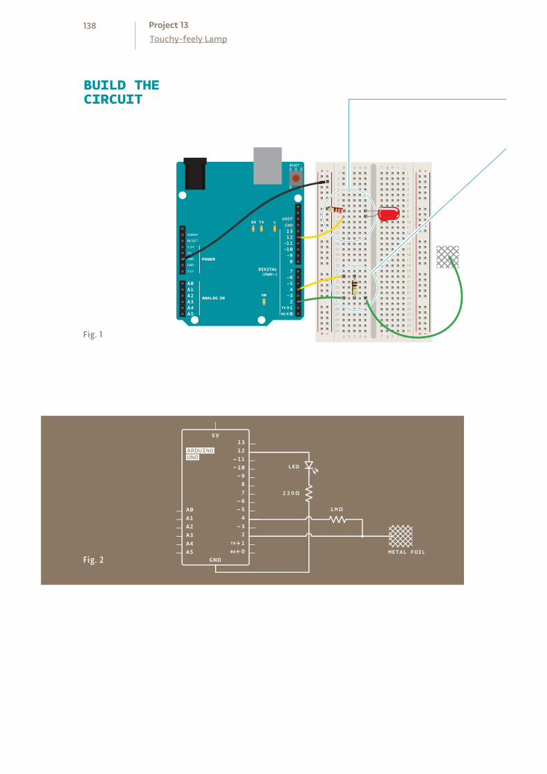
BUILD THECIRCUIT
Fig. 1
Fig. 2
138Touchy-feely LampProject 13

Connect an LED to pin 12, and connect the cathode to ground
through a 220-ohm resistor as shown.
Connect digital pins 2 and 4 to your breadboard. Connect the
two pins with a 1-megahom resistor. In the same row as pin 2,
insert a long wire (8-10cm at least) that extends away from the
breadboard, not connected to anything on the other end. This
will become your touch sensor.
Just like with other LED projects, diffusing the light will make this much more at-
tractive. Ping pong balls, little lampshades from paper or plastic, whatever you have
handy will work.
You can hide the sensor behind something solid and it will still work. Capacitance
can be measured through non-conductive materials like wood and plastic. Increas-
ing the surface area of the sensor with a larger conductive surface will make it more
sensitve; try connecting aluminum foil, or copper mesh to your wire. You could
make a base for the lamp out of cardboard, thin wood, or cloth, and line the inner
surface with foil attached to your sensor wire. The whole base of the lamp would
then act as a touch sensor. Update the threshold variable in the code when you
make these changes to ensure that you’re still getting a reliable result.
There’s no need to supply 5V to your breadboard in this project. Digital pin 4 supplies the current to the sensor.
❶
❷
139
At the beginning of your program, include the CapacitiveSensor
library. You include it the same way you would a native Arduino
library like the Servo library in the earlier projects.
Create a named instance of the library. When you use this library,
you tell the instance what pins it will be using to send and receive
information. In this case, pin 4 sends to the conductive sensor
material through the resistor, and pin 2 is the sense pin.
Set up a variable for the sensing threshold at which the lamp
will turn on. You’ll change this number after you test the sensor’s
functionality.
Then define the pin your LED will be on.
In the setup() function, open a Serial connection at 9600 bps.
You’ll use this to see the values the sensor reads. Also, make your
ledPin an OUTPUT.
In the loop() function, create a variable of type long to hold the
sensor’s value. The library returns the sensor value using a com-
mand called CapacitiveSensor() that takes an argument
identifying the number of samples you want to read. If you read
only a few samples, it’s possible you’ll see a lot of variation in the
sensor. If you take too many samples, you could introduce a lag
as it reads the sensor multiple times. 30 samples is a good start-
ing value. Print the sensor value to the serial monitor.
With an if()...else statement, check to see if the sensor
value is higher than the threshold. If it is, turn the LED on. If it is
not, turn it off.
Then add a small delay() before ending the loop().
THE CODE
Import the Capacit iveSensor l ibrary
Set up the threshold
Sensing touch
Lamp control
140Touchy-feely LampProject 13
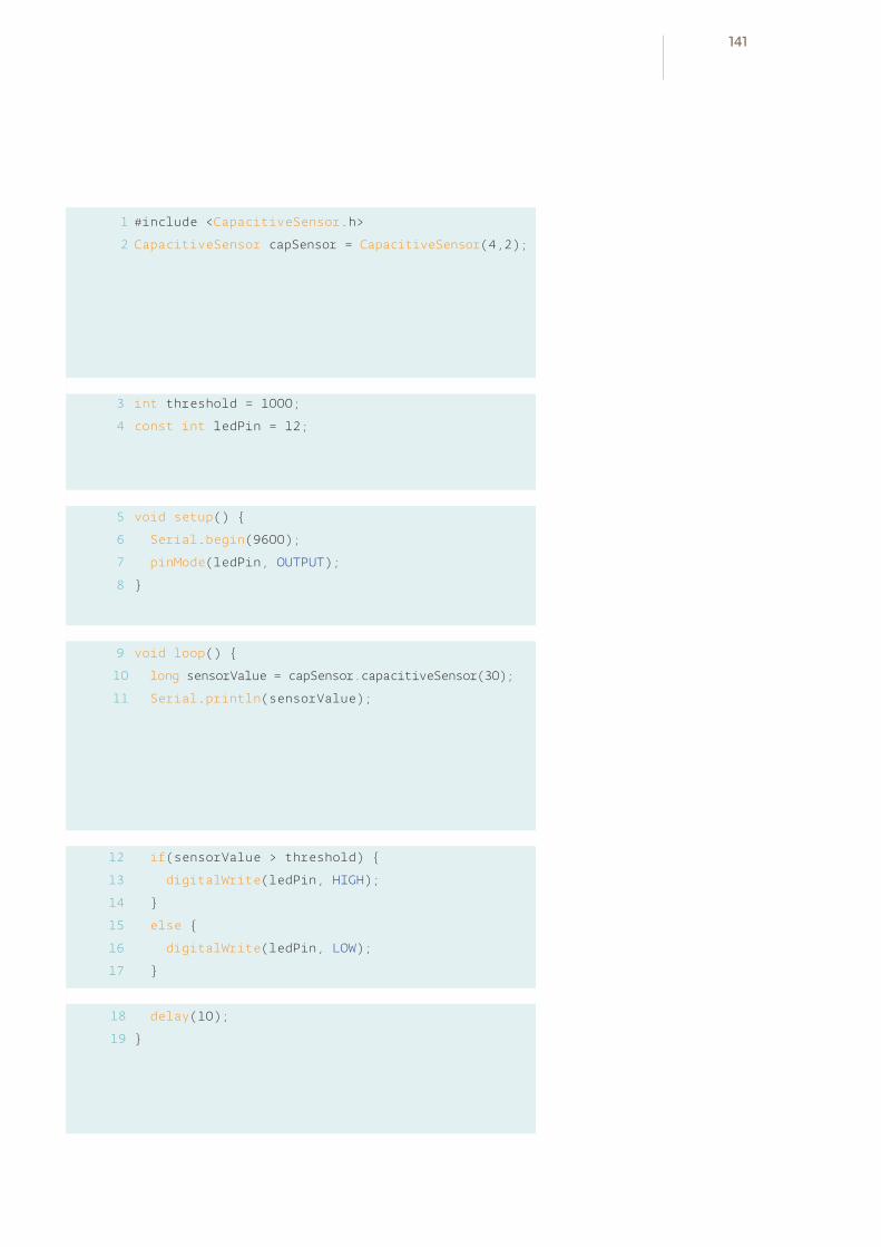
1
2
3
4
5
6
7
8
9
10
11
#include <CapacitiveSensor.h>
CapacitiveSensor capSensor = CapacitiveSensor(4,2);
int threshold = 1000;
const int ledPin = 12;
void setup()
Serial.begin(9600);
pinMode(ledPin, OUTPUT);
void loop()
long sensorValue = capSensor.capacitiveSensor(30);
Serial.println(sensorValue);
if(sensorValue > threshold)
digitalWrite(ledPin, HIGH);
else
digitalWrite(ledPin, LOW);
delay(10);
12
13
14
15
16
17
18
19
141

Third party libraries like Paul Badger’s CapacitiveSensor are useful tools for expanding the capabilities of the Arduino. Once installed, they behave similarly to libraries that are bundled with the core software.
After programming the Arduino, you’ll want to find out what
the sensor values are when it’s touched. Open the serial moni-
tor and note the value coming from the sensor when you’re not
touching it. Press gently on the bare wire you have exposed from
your breadboard. The number should increase. Try pressing more
firmly and see if it changes.
Once you have an idea of the range of values you’re getting from
the sensor, go back to the sketch and change the threshold vari-
able to a number that is greater than the sensor’s value when
it is not touched, but less than its value when pressed. Upload
the sketch with the new value. The light should come on reliably
when you touch the wire, and turn off when it’s left alone. If you
aren’t getting the light to turn on, try lowering the threshold a
little more.
USE IT
You probably noticed that the values from the sensor changed depending on how
much of your finger was touching the conductor. Can you use this to get other
interactions with the LED? What about multiple sensors for fading the light brighter
and darker? If you place a different value resistor between pins 2 and 4 it will change
the sensitivity. Is this useful for your interface?
142Touchy-feely LampProject 13


INGREDIENTS
14POTENTIOMETER
USING SERIAL COMMUNICATION, YOU’LL USE YOUR ARDUINO TO CONTROL A PROGRAM ON YOUR COMPUTER
You’ve done a lot of cool stuff with the physical world, now it’s time to control your computer with your Arduino. When you program your Arduino, you’re opening a connection between the computer and the microcontroller. You can use this connection to send data back and forth to other applications.
The Arduino has a chip that converts the computer’s USB-based communication
to the serial communication the Arduino uses. Serial communication means that
the two computers, your Arduino and PC, are exchanging bits of information
serially, or one after another in time.
When communicating serially, computers need to agree on the speed at which
they talk to one another. You’ve probably noticed when using the serial monitor
there’s a number at the bottom right corner of the window. That number, 9600
bits per second, or baud, is the same as the value you’ve declared using Serial.
begin(). That’s the speed at which the Arduino and computer exchange data.
A bit is the smallest amount of information a computer can understand.
You’ve used the serial monitor to look at values from the analog inputs; you’ll
use a similar method to get values into a program you’re going to write in a
programming environment called Processing. Processing is based on Java, and
Arduino’s programming environment is based on Processing’s. They look pretty
similar, so you should feel right at home there.
Before getting started with the project, download the latest version of Processing
from processing.org. It may be helpful to look at the “Getting started” and
“Overview” tutorials at processing.org/learning. These will help you to familiarize
yourself with Processing before you start writing software to communicate with
your Arduino.
Time: 45 MINUTESLevel:
Builds on projects: 1, 2, 3
Discover: serial communication with a computer program, Processing
TWEAK THE ARDUINO LOGO
145
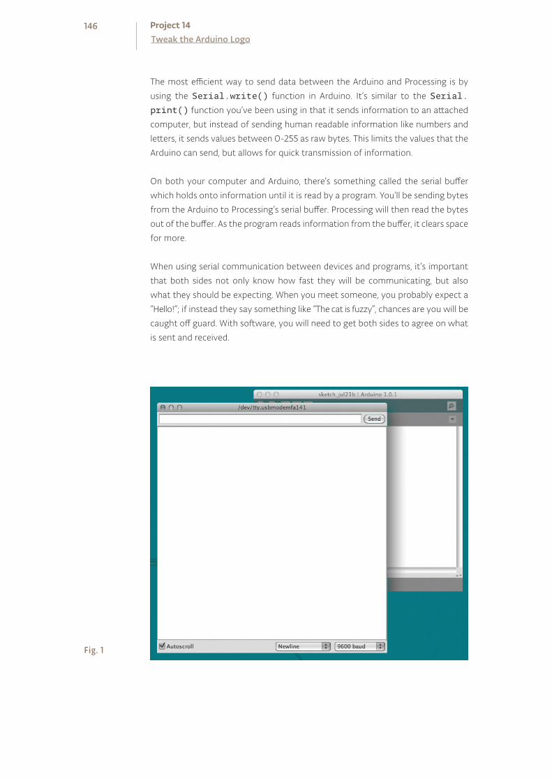
The most efficient way to send data between the Arduino and Processing is by
using the Serial.write() function in Arduino. It’s similar to the Serial.
print() function you’ve been using in that it sends information to an attached
computer, but instead of sending human readable information like numbers and
letters, it sends values between 0-255 as raw bytes. This limits the values that the
Arduino can send, but allows for quick transmission of information.
On both your computer and Arduino, there’s something called the serial buffer
which holds onto information until it is read by a program. You’ll be sending bytes
from the Arduino to Processing’s serial buffer. Processing will then read the bytes
out of the buffer. As the program reads information from the buffer, it clears space
for more.
When using serial communication between devices and programs, it’s important
that both sides not only know how fast they will be communicating, but also
what they should be expecting. When you meet someone, you probably expect a
“Hello!”; if instead they say something like “The cat is fuzzy”, chances are you will be
caught off guard. With software, you will need to get both sides to agree on what
is sent and received.
Fig. 1
146Tweak the Arduino LogoProject 14

Fig. 2
Fig. 3
BUILD THECIRCUIT
Connect power and ground to your breadboard.
Connect each end of your potentiometer to power and ground.
Connect the middle leg to analogIn pin 0.
❶❷
147
First, program your Arduino. In setup(), you’ll start serial
communication, just as you did earlier when looking at the values
from an attached sensor. The Processing program you write will
have the same serial baud rate as your Arduino.
In the loop(), you’re going to use the Serial.write()
command to send information over the serial connection.
Serial.write() can only send a value between 0 and 255. To
make sure you’re sending values that fit within that range, divide
the analog reading by 4.
After sending the byte, wait for one millisecond to let the ADC
settle down. Upload the program to the Arduino then set it aside
while you write your Processing sketch.
THE ARDUINOCODE
THE PROCESSINGCODE
The Processing language is similar to Arduino, but there are
enough differences that you should look at some of their
tutorials and the “Getting Started” guide mentioned before to
familiarize yourself with the language.
Open a new Processing sketch. Processing, unlike the Arduino,
doesn’t know about serial ports without including an external
library. Import the serial library.
You need to create an instance of the serial object, just like you’ve
done in Arduino with the Servo library. You’ll use this uniquely
named object whenever you want to use the serial connection.
To use images in Processing, you need to create an object that
will hold the image and give it a name.
Open a ser ia l connect ion
Send the sensor value
Let the ADC stabi l ize
Import the set up the ser ia l object
Create an object for the image
148Tweak the Arduino LogoProject 14

1
2
3
void setup()
Serial.begin(9600);
void loop()
Serial.write(analogRead(A0)/4);
delay(1);
4
5
6
7
1
2
import processing.serial.*;
Serial myPort;
PImage logo;
SAVE AND CLOSE THE ARDUINO IDE NOW, LET’S START PROCESSING.
3
149

Create a variable that will hold the background hue of the Arduino
logo. The logo is a .png file, and it has built-in transparency, so it’s
possible to see the background color change.
Processing has a setup() function, just like Arduino. Here’s
where you’ll open the serial connection and give the program a
couple of parameters that will be used while it runs.
You can change the way Processing works with color information.
Typically, it works with colors in a Red Green Blue (RGB) fashion.
This is similar to the color mixing you did in Project 4, when you
used values between 0 and 255 to change the color of an RGB
LED. In this program, you’re going to use a color mode called
HSB, which stands for Hue, Saturation, and Brightness. You’ll
change the hue when you turn the potentiometer.
colorMode() takes two arguments: the type of mode, and the
maximum value it can expect.
To load the Arduino image into the sketch, read it into the logo
object you created earlier. When you supply the URL of an image,
Processing will download it when you run the program.
With the size() function, you tell Processing how large the
display window will be. If you use logo.width and logo.
height as the arguments, the sketch will automatically scale to
the size of the image you’re using.
Processing has the ability to print out status messages using the
println() command. If you use this in conjunction with the
Serial.list() function, you’ll get a list of all the serial ports
your computer has when the program first starts. You’ll use this once
you’re finished programming to see what port your Arduino is on.
You need to tell Processing information about the serial
connection. To populate your named serial object myPort with
the necessary information, the program needs to know it is a
new instance of the serial object. The parameters it expects are
which application it will be speaking to, which serial port it will
communicate over, and at what speed.
Variable to store the background color
Sett ing the color mode
Loading the image
Print ing avai lable ser ia l ports
Creat ing the ser ia l object
150Tweak the Arduino LogoProject 14
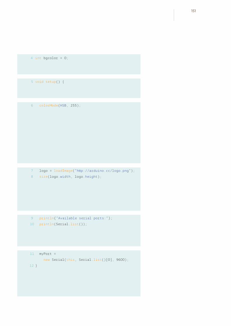
4 int bgcolor = 0;
void setup()
colorMode(HSB, 255);
logo = loadImage(“http://arduino.cc/logo.png”);
size(logo.width, logo.height);
println(“Available serial ports:”);
println(Serial.list());
myPort =
new Serial(this, Serial.list()[0], 9600);
5
6
7
8
9
10
11
12
151
The attribute this tells Processing you’re going to use the serial
connection in this specific application. The Serial.list()
[0] argument specifies which serial port you’re using. Serial.
list() contains an array of all the attached serial devices. The
argument 9600 should look familiar, it defines the speed at
which the program will communicate.
The draw() function is analogous to Arduino’s loop() in that
it happens over and over again forever. This is where things are
drawn to the program’s window.
Check if there is information from the Arduino. The myPort.
available() command will tell you if there is something in
the serial buffer. If there are bytes there, read the value into the
bgcolor variable and print it to the debug window.
The function background() sets the color of the window. It
takes three arguments. The first argument is the hue, the next
is brightness, and the last is saturation. Use the variable bgcolor
as the hue value, and set the brightness and saturation to the
maximum value, 255.
You’ll draw the logo with the command image(). You need
to tell image() what to draw, and what coordinates to start
drawing it in the window. 0,0 is the top left, so start there.
USE IT Connect your Arduino and open the serial monitor. Turn the
pot on your breadboard. You should see a number of charac-
ters as you twist the knob. The serial monitor expects ASCII
characters, not raw bytes. ASCII is information encoded to
represent text in computers. What you see in the window is
the serial monitor trying to interpret the bytes as ASCII.
When you use Serial.println(), you send information
formatted for the serial monitor. When you use Serial.
write(), like in this application you are running now, you’re
sending raw information. Programs like Processing can
understand these raw bytes.
Reading Arduino data from the ser ia l port
Sett ing the image background and displaying the image
152Tweak the Arduino LogoProject 14

void draw()
if (myPort.available() > 0)
bgcolor = myPort.read();
println(bgcolor);
background(bgcolor, 255, 255);
image(logo, 0, 0);
13
14
15
16
17
18
19
20
153
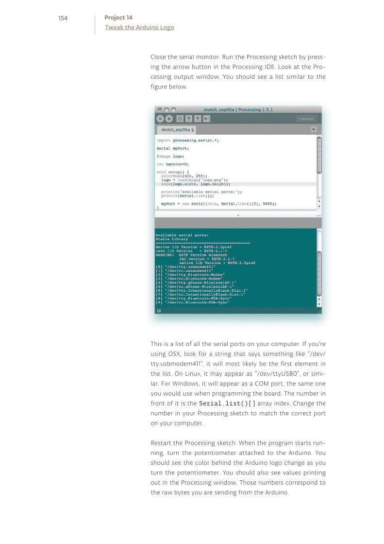
Close the serial monitor. Run the Processing sketch by press-
ing the arrow button in the Processing IDE. Look at the Pro-
cessing output window. You should see a list similar to the
figure below.
This is a list of all the serial ports on your computer. If you’re
using OSX, look for a string that says something like “/dev/
tty.usbmodem411”, it will most likely be the first element in
the list. On Linux, it may appear as “/dev/ttyUSB0”, or simi-
lar. For Windows, it will appear as a COM port, the same one
you would use when programming the board. The number in
front of it is the Serial.list()[] array index. Change the
number in your Processing sketch to match the correct port
on your computer.
Restart the Processing sketch. When the program starts run-
ning, turn the potentiometer attached to the Arduino. You
should see the color behind the Arduino logo change as you
turn the potentiometer. You should also see values printing
out in the Processing window. Those numbers correspond to
the raw bytes you are sending from the Arduino.
154Tweak the Arduino LogoProject 14
Once you have twisted and turned to your heart’s desire, try replacing the pot
with an analog sensor. Find something you find interesting to control the color.
What does the interaction feel like? It’s probably different than using a mouse or
keyboard, does it feel natural to you?
When using serial communication, only one application can talk to the Arduino at a
time. So if you’re running a Processing sketch that is connected to your Arduino, you
won’t be able to upload a new Arduino sketch or use the serial monitor until you’ve
closed the active application.
With Processing and other programming environments, you can control media on
your computer in some remarkable and novel ways. If you’re excited about the pos-
sibilities of controlling content on your computer, take some time to experiment
with Processing. There are several serial communication examples in both the Pro-
cessing and Arduino IDEs that will help you explore further.
Serial communication enables the Arduino to talk with programs on a computer. Processing is an open source programming environment that the Arduino IDE is based upon. It’s possible to control a Processing sketch with the Arduino via serial communication.
155

INGREDIENTS
15220 OHM RESISTOR
OPTOCOUPLER
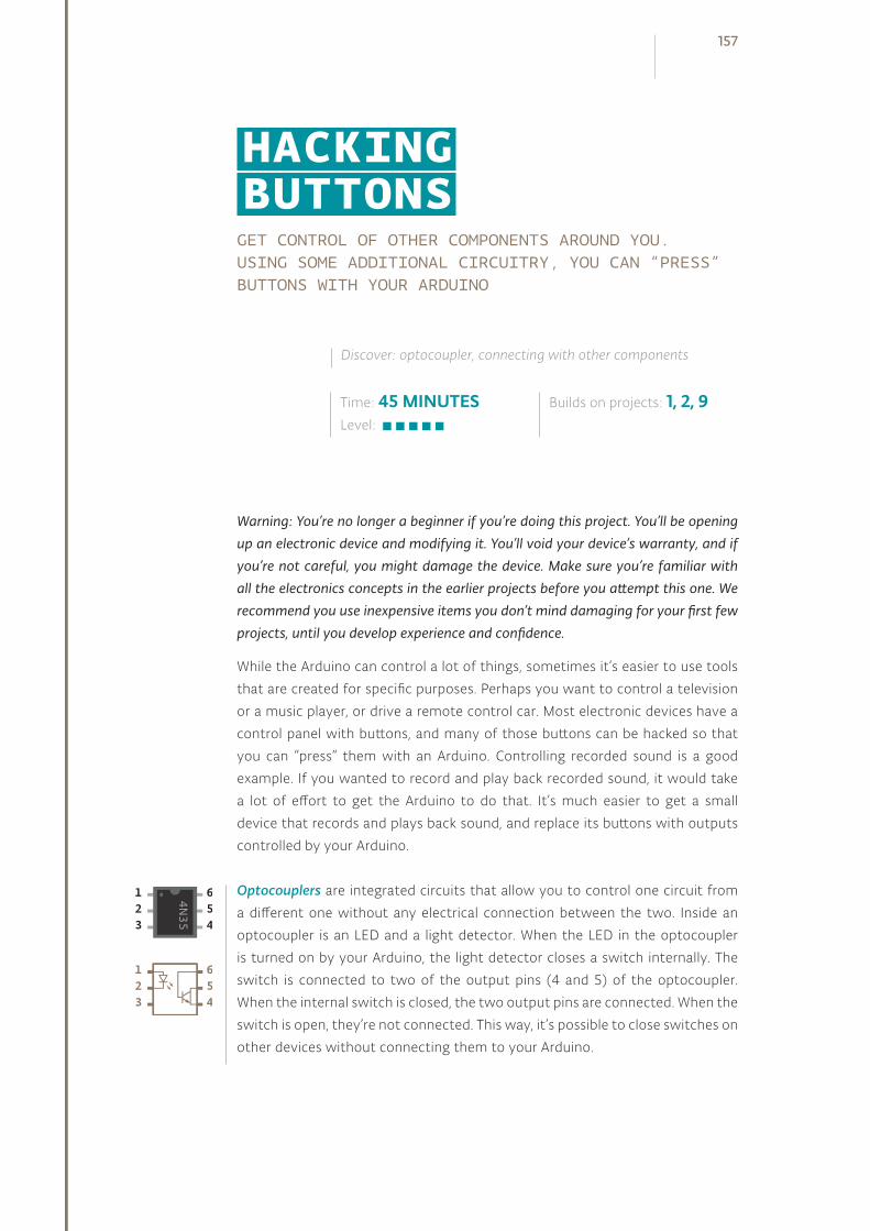
GET CONTROL OF OTHER COMPONENTS AROUND YOU. USING SOME ADDITIONAL CIRCUITRY, YOU CAN “PRESS” BUTTONS WITH YOUR ARDUINO
Warning: You’re no longer a beginner if you’re doing this project. You’ll be opening up an electronic device and modifying it. You’ll void your device’s warranty, and if you’re not careful, you might damage the device. Make sure you’re familiar with all the electronics concepts in the earlier projects before you attempt this one. We recommend you use inexpensive items you don’t mind damaging for your first few projects, until you develop experience and confidence.
While the Arduino can control a lot of things, sometimes it’s easier to use tools
that are created for specific purposes. Perhaps you want to control a television
or a music player, or drive a remote control car. Most electronic devices have a
control panel with buttons, and many of those buttons can be hacked so that
you can “press” them with an Arduino. Controlling recorded sound is a good
example. If you wanted to record and play back recorded sound, it would take
a lot of effort to get the Arduino to do that. It’s much easier to get a small
device that records and plays back sound, and replace its buttons with outputs
controlled by your Arduino.
Optocouplers are integrated circuits that allow you to control one circuit from
a different one without any electrical connection between the two. Inside an
optocoupler is an LED and a light detector. When the LED in the optocoupler
is turned on by your Arduino, the light detector closes a switch internally. The
switch is connected to two of the output pins (4 and 5) of the optocoupler.
When the internal switch is closed, the two output pins are connected. When the
switch is open, they’re not connected. This way, it’s possible to close switches on
other devices without connecting them to your Arduino.
Time: 45 MINUTESLevel:
Builds on projects: 1, 2, 9
Discover: optocoupler, connecting with other components
HACKING BUTTONS
157

BUILD THECIRCUIT
Fig. 1
Fig. 2
In this example, the diagrams are for controlling a digital recording module that allows you to
record and playback 20 seconds of sound, but the basic premise holds for any device that has
a switch you can access. While it’s possible to use this example without soldering any wires, it
certainly makes things easier. For more information on soldering, see p. 134.
158Hacking ButtonsProject 15

Connect ground to your breadboard through the Arduino.
Place the optocoupler on your breadboard so that it straddles
the center of the board (see circuit diagram).
Connect pin 1 on the optocoupler to Arduino pin 2 in series with
a 220-ohm resistor (remember, you’re powering an LED inside,
you don’t want to burn it out). Connect pin 2 of the optocou-
pler to ground.
On the main board of the sound module there are a number of
electrical components, including a playback button.
To control the switch, you’re going to have to remove the but-
ton. Flip the circuit board over and find the tabs that hold the
button in place. Gently bend the tabs back and remove the but-
ton from the board.
Under the button are two small metal plates. This pattern is
typical of many electronic devices with pushbuttons. The two
“forks” of this pattern are the two sides of the switch. A small
metal disc inside the pushbutton connects these two forks
when you press the button.
When the forks are connected, the switch is closed on the circuit
board. You will be closing the switch with the optocoupler.
This method, closing a switch with an optocoupler, works only if
one of the two sides of the pushbutton’s switch is connected to
ground on your device. If you’re not sure, take a multimeter and
measure the voltage between one of the forks and the ground
on your device. You need to do this with the device turned on, so
be careful not to touch anywhere else on the board.
Once you know which fork is ground, disconnect the power to
your device.
Next, connect one wire to each of the small metal plates. If you
are soldering these wires, be careful to not join the two sides
of the switch together. If you are not soldering and using tape,
make sure your connection is secure, or the switch won’t close.
Make sure neither wire connects to the other fork, or your switch
will be closed all the time.
Attach the two wires to pins 4 and 5 of the optocoupler. Connect
the side of the switch that is grounded to pin 4 of the optocou-
pler. Connect the other fork to pin 5 of the optocoupler.
❶❷
❸
❹
❺
❻
❼
❽
159

Most of the fun with this project is in the circuit and the
optocoupler. The code is similar to the first project you made
with the Arduino. You’re going to play the sound once every 20
seconds by turning pin 2 HIGH.
Create a constant for the optocoupler control pin.
In setup(), set the optocoupler pin into an output.
The loop() turns optoPin HIGH for a few milliseconds, long
enough for the optocoupler to close the switch on the device.
Then the optoPin becomes LOW.
Wait for 21 seconds for the whole message to play back before
starting the loop() again.
THE CODE
Attach the battery to the sound recorder. Press and hold the
record button on the device. While you’re holding the button,
you can record audio into the microphone. Use your voice, the
cat, or the pots and pans in the kitchen to make some noise
(but be careful with the cat).
Once you’ve satisfactorily recorded a sound, power your Ar-
duino with the USB cable. Your recording should start to play.
If you recorded for the full 20 seconds, the sound should start
again just a few moments after it ends.
USE IT
Try experimenting with different sounds and durations of toggling the playback
with the delay() in your program.
If you trigger the switch while a sound is playing, it will stop. How can you take
advantage of this to create unique sequences of sounds?
Name a constant
Configure the pin direct ion
Pul l the pin high and low
Wait for a l i tt le whi le
160Hacking ButtonsProject 15
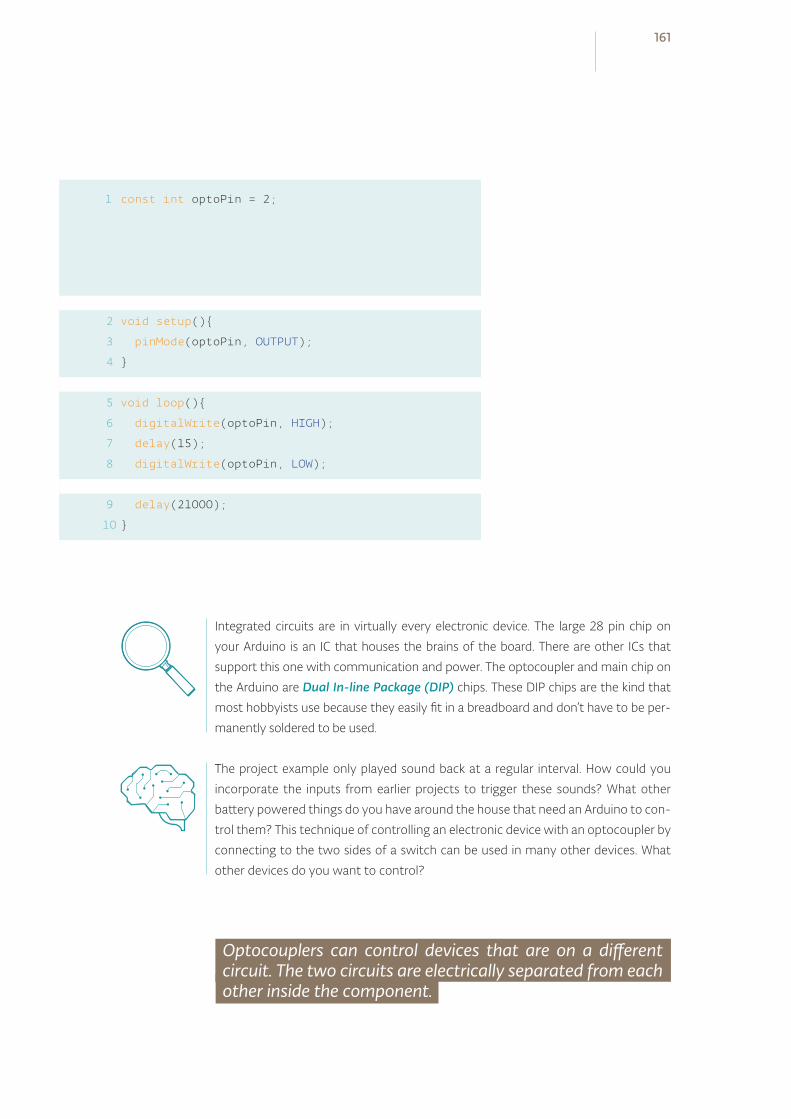
1 const int optoPin = 2;
void setup()
pinMode(optoPin, OUTPUT);
void loop()
digitalWrite(optoPin, HIGH);
delay(15);
digitalWrite(optoPin, LOW);
delay(21000);
2
3
4
5
6
7
8
9
10
Integrated circuits are in virtually every electronic device. The large 28 pin chip on
your Arduino is an IC that houses the brains of the board. There are other ICs that
support this one with communication and power. The optocoupler and main chip on
the Arduino are Dual In-line Package (DIP) chips. These DIP chips are the kind that
most hobbyists use because they easily fit in a breadboard and don’t have to be per-
manently soldered to be used.
The project example only played sound back at a regular interval. How could you
incorporate the inputs from earlier projects to trigger these sounds? What other
battery powered things do you have around the house that need an Arduino to con-
trol them? This technique of controlling an electronic device with an optocoupler by
connecting to the two sides of a switch can be used in many other devices. What
other devices do you want to control?
Optocouplers can control devices that are on a different circuit. The two circuits are electrically separated from each other inside the component.
161

A/Z
GLOSSARY
Accelerometer -
Actuator -
Alternating current -
Amperage (amps or amperes) -
Analog -
Analog-to-Digital Converter
(ADC) -
Anode -
Argument -
Array -
Back-voltage -
Baud -
Binary -
Bit -
Boolean -
Byte -
Calibration -
Capacitance -
Cathode -
Circuit -
Common cathode LED -
Conductor -
Constant -
Current -
Datasheet -
Datatype -
Debugging -
Decoupling capacitors -
Digital -
Direct current -
Drain (transistor) -
Dual In-line Package (DIP) -
Duty cycle -
Electricity -
Float -
Function -
Gate -
Global variable -
Ground -
IDE -
Index -
Induction -
Instance -
Insulator -
Int -
Integrated Circuit (IC)-
Library -
Load -
Local variable -
Long -
Microcontroller -
Millisecond -
Object -
Ohm -
Ohm’s Law -
Optocoupler -
Parallel -
Parameter -
Period -
Photocell -
Photoresistor -
Phototransistor -
Polarized -
Power supply -
Processing -
Pseudocode -
Pulse Width Modulation
(PWM) -
Resistance -
Sensor -
Serial buffer -
Serial communication -
Serial monitor -
Series -
Short circuit -
Sketch -
Soldering -
Source (transistor) -
Square wave -
Switch -
Transducer -
Transistor -
Unsigned -
USB -
Variable -
Voltage -
Voltage divider -
GLOSSARYTHERE ARE A NUMBER OF NEW TERMS
YOU’VE LEARNED IN THESE PROJECTS.
WE’VE COLLECTED THEM ALL HERE FOR
REFERENCE
163
AAccelerometer - A sensor that measures ac-
celeration. Sometimes, they are used to detect
orientation, or tilt.
Actuator - A type of component that changes
electrical energy into motion. Motors are a type
of actuator.
Alternating current - A type of current where
electricity changes its direction periodically.
This is the sort of electricity that comes out of
a wall socket.
Amperage (amps or amperes) - The amount of
electrical charge flowing past a specific point
in your circuit. Describes the current as it flows
through a conductor, like a wire.
Analog - Something that can continuously vary
over time.
Analog-to-Digital Converter (ADC) - A circuit
that converts an analog voltage into a digital
number representing that voltage. This circuit
is built-in to the microcontroller, and is con-
nected to the analog input pins A0-A5. Con-
verting an analog voltage into a digital number
takes a tiny bit of time, so we always follow the
analogRead() with a short delay().
Anode - The positive end of a capacitor or diode
(remember that an LED is a type of diode).
Argument - A type of data supplied to a func-
tion as an input. For example, for digitalRead()
to know what pin to check, it takes an argu-
ment in the form of a pin number.
Array - In programming, this is a group of vari-
ables that are identified by one name, and ac-
cessed by an index number.
BBack-voltage - Voltage that pushes back
against the current that created it. It can be
created by motors spinning down. This can
damage circuits, which is why diodes are often
used in conjunction with motors.
Baud - Shorthand for “bits per second”, signify-
ing the speed at which computers are commu-
nicating with each other.
Binary - A system with only two states, like
true/false or off/on.
Bit - The smallest piece of information a com-
puter can send or receive. It has two states, 0
and 1.
Boolean - A datatype that indicates if some-
thing is true or false.
Byte - 8 bits of information. A byte can hold a
number between 0 and 255.
CCalibration - The process of making adjustments
to certain numbers or components to get the
best results from a circuit or program. In Arduino
projects, this is often used when sensors in the
real world may give different values in different
circumstances, for instance the amount of light
on a photoresistor. Calibration can be automatic,
as in Project 6, or manual, as in Project 3.
Capacitance - The ability of something to
hold an electrical charge. This charge can be
measured with the Capacitive Sensor library,
as seen in Project 13.
Cathode - The end of a capacitor or diode that
typically connects to ground.
Circuit - A circular path from a power supply,
through a load, and then back again to the
other end of the power supply. Current flows
in a circuit only if it is closed, that is, if the out-
going and return path are both uninterrupted,
or closed. If either path is interrupted, or open,
then current will not flow through the circuit.
Common cathode LED - Types of LEDs that
have multiple colors in one fixture, with one
cathode and multiple anodes.
Conductor - Something that enables electricity
to flow, like a wire.
Constant - A named identifier that cannot
change its value in a program.
Current - The flow of electrical charge through a
closed circuit. Measured in amps.
DDatasheet - A document written by engineers
for other engineers that describes the design
and functionality of electrical components.
Typical information in a datasheet includes the
maximum voltage and current a component
requires, as well as an explanation of the func-
tionality of the pins.
Datatype - A classification system that deter-
mines what values a particular constant, varia-
ble, or array will hold. Int, float, long and boolean
are all types that can be used in Arduino.
Debugging - The process of going through a cir-
cuit or code, and finding errors (also referred as
“bugs”), until the expected behavior is achieved.
164 Glossary
Decoupling capacitors - Capacitors that are
used to regulate spikes and dips in voltage, of-
ten placed close to a sensor or actuator.
Digital - A system of discrete values. As Arduino
is a type of digital device, it only knows of two
discrete states, off and on, nothing in between.
Direct current - A type of current which always
flows in the same direction. All the projects in
this kit use direct current.
Drain (transistor) - The pin that connects to the
higher current/voltage load to be controlled.
Dual In-line Package (DIP) - A type of packaging
for integrated circuits that allows the compo-
nents to be easily inserted into a breadboard.
Duty cycle - A ratio indicating the amount of
time over a certain period that a component
is turned on. When using a PWM value of 127
(out of a total of 256), you’re creating a 50%
duty cycle.
EElectricity - A type of energy generated by
electric charges. You can use electronic com-
ponents to change electricity to other forms of
energy, like light and heat.
FFloat - A datatype that can be expressed as a
fraction. This entails the use of decimal points
for floating point numbers.
Function - A block of code that executes a spe-
cific task repeatedly.
GGate - The pin on a transistor that is connected
to the Arduino. When the gate is turned on,
by applying 5V, it closes the junction between
drain and source, completing the circuit it is
connected to.
Global variable - A named variable that can be
accessed anywhere inside your program. It is
declared before the setup() function.
Ground - The point of a circuit where there is 0
potential electrical energy. Without a ground,
electricity will not have a place to flow in a
circuit.
IIDE - Stands for “Integrated Development En-
vironment”. The Arduino IDE is the place where
you write software to upload to the Arduino. It
contains all the functions the Arduino can un-
derstand. Other programming environments,
like Processing, have their own IDE.
Index - The number supplied to an array that
indicates which element you’re referring to.
Computers are zero-indexed, which means
they start counting at 0 instead of 1. To access
the third element in an array named tones, for
example, you would write tones[2].
Induction - The process of using electrical en-
ergy to create a magnetic field. This is used in
motors to spin them around.
Instance - A copy of a software object. You’re
using instances of the Servo library in Projects 5
and 12, in each case, you’re creating a named in-
stance of the Servo library to use in the project.
165
Insulator - Something that prevents electricity
from flowing. Conductive materials like wires
are often covered in insulators like rubber.
Int - A datatype that holds a whole number be-
tween −32,768 and 32,767.
Integrated Circuit (IC) - A circuit that has been
created on a tiny piece of silicon and embedded
in plastic (or epoxy). Pins, or legs, protruding
from the body allow you to interact with the
circuit inside. Very often we can make good use
of an IC knowing only what to connect to the
pins without having to understand how it func-
tions internally.
LLibrary - A piece of code that expands the func-
tionality of a program. In the case of Arduino li-
braries, they either enable communication with
a particular piece of hardware, or are used for
manipulating data.
Load - A device that turns electrical energy into
something else, such as light, heat, or sound.
Local variable - A type of variable that is used
for a short amount of time, then forgotten. A
variable declared inside the setup() of a pro-
gram would be local: after the setup() finished
running, the Arduino would forget that the vari-
able ever existed.
Long - A datatype that can hold a very large
number, from −2,147,483,648 to 2,147,483,647.
MMicrocontroller - The brains of the Arduino, this
is a small computer that you will program to lis-
ten for, process, and display information.
Millisecond - 1/1,000th of a second. The Arduino
goes through its programs so fast, when call-
ing delay() and other time based functions, it’s
done in milliseconds.
OObject - An instance of a library. When using the
Servo library, were you to create an instance
named myServo, myServo would be the object.
Ohm - Unit of measurement of resistance. Rep-
resented by the omega symbol (Ω).
Ohm’s Law - A mathematical equation that
demonstrates the relationship between resist-
ance, current and voltage. Usually stated as V
(voltage) = I (current) x R (resistance).
Optocoupler - Also known as an opto-isolator,
photo-coupler, photo-isolator, photo-switch,
and opto-switch. An LED is combined in a
sealed case with a phototransistor. The LED is
positioned to illuminate the phototransistor, so
that when the LED is turned on, the phototran-
sistor will conduct. Used to provide a high de-
gree of isolation as there is no electrical con-
nection common to the input and the output.
PParallel - Components connected across the
same two points in a circuit are in parallel. Par-
allel components always have the same voltage
drop across them.
Parameter - When declaring a function, a
166 Glossary
named parameter serves as the bridge between
the local variables in the function, and the argu-
ments it receives when the function is called.
Period - A specific span of time in which some-
thing happens. When the period changes,
you’re adjusting the frequency at which some-
thing will occur.
Photocell - A device for converting light energy
to electrical energy.
Photoresistor - A resistive device whose resist-
ance varies according to how much light falls
on it.
Phototransistor - A transistor which is con-
trolled by light rather than by current.
Polarized - The leads of polarized components
(e.g. LEDs or capacitors) have different func-
tions, and thus must be connected the right
way. Polarized components connected the
wrong way might not work, might be damaged,
or might damage other parts of your circuit.
Non-polarized components (e.g. resistors) can
be connected either way.
Power supply - A source of energy, usually a bat-
tery, transformer, or even the USB port of your
computer. Comes in many varieties such as
regulated or unregulated, AC or DC. Usually the
voltage is specified, along with the maximum
current the supply can deliver before failing.
Processing - A programming environment
based on the Java language. Used as a tool to
introduce people to the concepts of program-
ming, and in production environments.
The Arduino IDE is written in Processing, and so
will look very familiar. In addition, Processing
and Arduino share a similar philosophy and mo-
tive, of creating free open source tools allowing
non-technical people to work with hardware
and software.
Pseudocode - A bridge between writing in a
computer programming language and using
natural speech. When creating pseudocode, it’s
helpful to write in short declarative statements.
Pulse Width Modulation (PWM) - A way to sim-
ulate an analog output when using a digital de-
vice, PWM involves turning a pin on and off at a
very rapid rate.The ratio of ON time to OFF time
determines the simulated analog result.
RResistance - A measure of how efficiently a
material will conduct electricity. In particular,
resistance can be calculated by Ohm’s Law as:
R = V/I.
SSensor - A component that measures one form
of energy (like light or heat or mechanical en-
ergy) and converts it to electrical energy, which
the Arduino can understand.
Serial buffer - A place in your computer’s and
microcontroller’s memory where information
received in serial communication is stored until
it is read by a program.
Serial communication - The means by which
the Arduino communicates with computers
and other devices. It involves sending one bit of
information at a time in a sequential order. The
Arduino has a USB-to-serial converter onboard,
which enables it to talk with devices that don’t
have a dedicated serial port.
Serial monitor - A tool built in to the Arduino
IDE allowing sending and receiving serial data
to and from a connected Arduino. See the
167
Serial() set of functions.
Series - Components are in series when current
flows from the first into the next. The current
flowing through both is the same, and the volt-
age drops across each component.
Short circuit - A short circuit between power
and ground will make your circuit stop work-
ing and thus should be avoided. In some cases
this might damage your power supply or parts
of your circuit, and rare cases might start a fire.
Sketch - The term given to programs written in
the Arduino IDE.
Soldering - The process of making an electri-
cal connection by melting solder over electrical
components or wires that are to be connected.
This provides a solid connection between com-
ponents.
Source (transistor) - The pin on a transistor that
connects to ground. When the gate receives
power, the source and drain are connected,
completing the circuit that is being controlled.
Square wave - A type of waveform that is iden-
tified by having only two states, on and off.
When used to generate tones, they can sound
“buzzy”.
Switch - A component that can open or close an
electrical circuit. There are many different kinds of
switches; the ones in the kit are momentary mean-
ing, they only close the circuit while being pressed.
TTransducer - Something that changes one form
of energy into another.
Transistor - A 3 terminal (usually) electronic
device which can act as either an amplifier or
a switch. A control voltage or current between
two leads controls a (usually) higher voltage or
current between a different pair of leads. Com-
mon types of transistors include the Bipolar
Junction Transistor (BJT) and the Metal Oxide
Semiconductor Field Effect Transistor (MOS-
FET). Often used to allow a small current from
an Arduino (limited to 40 mA) to control sub-
stantially larger currents, such as those needed
by motors, relays, or incandescent lamps. De-
pending on how they are constructed, transis-
tors are either N-channel or P-channel, which
determines how they should be connected.
UUnsigned - A term used to describe some data-
types, indicating that they cannot be a negative
number. It’s helpful to have an unsigned num-
ber if you only need to count in one direction.
For instance, when keeping track of time with
millis(), it’s advisable to use the unsigned long
datatype.
USB - Stands for Universal Serial Bus. It’s a ge-
neric port that is standard on most computers
today. With a USB cable, it’s possible to program
and power an Arduino over a USB connection.
VVariable - A place in your computer’s or mi-
crocontroller’s memory for storing informa-
tion needed in a program. Variables store
values which are likely to change as your pro-
gram runs. A variable’s type depends on the
type of information you want to store, and
the maximum size of the information; for
example, a byte can store up to 256 differ-
168 Glossary
ent values, but an int can store up t 65,536
different values. Variables can be local to a
particular block of code, or global to an entire
program. (see Global variable, Local variable).
Voltage - A measure of potential energy, that
a charge might be pushed with if provided a
closed circuit.
Voltage divider - A type of circuit that provides
an output that is a fraction of its input voltage.
You are building a voltage divider when you
combine a photoresistor with a fixed resistor
to provide an analog input. A potentiometer is
another example of a voltage divider.
169
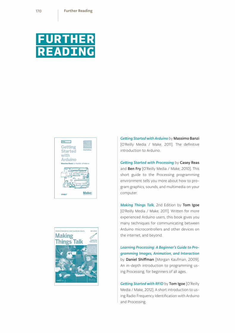
Getting Started with Arduino by Massimo Banzi [O’Reilly Media / Make, 2011]. The definitive
introduction to Arduino.
Getting Started with Processing by Casey Reas
and Ben Fry [O’Reilly Media / Make, 2010]. This
short guide to the Processing programming
environment tells you more about how to pro-
gram graphics, sounds, and multimedia on your
computer.
Making Things Talk, 2nd Edition by Tom Igoe [O’Reilly Media / Make, 2011]. Written for more
experienced Arduino users, this book gives you
many techniques for communicating between
Arduino microcontrollers and other devices on
the internet, and beyond.
Learning Processing: A Beginner’s Guide to Pro-gramming Images, Animation, and Interaction
by Daniel Shiffman [Morgan Kaufman, 2009].
An in-depth introduction to programming us-
ing Processing, for beginners of all ages.
Getting Started with RFID by Tom Igoe [O’Reilly
Media / Make, 2012]. A short introduction to us-
ing Radio Frequency Identification with Arduino
and Processing.
FURTHERREADING
170 Further Reading
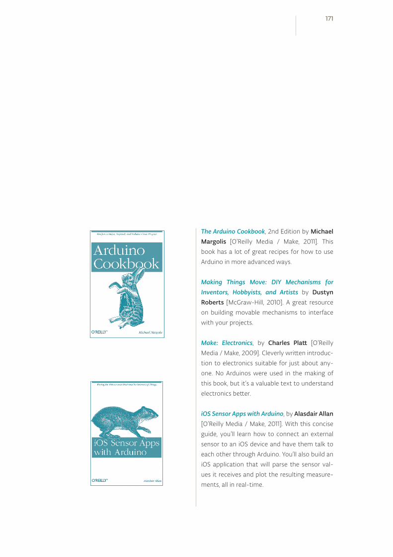
The Arduino Cookbook, 2nd Edition by Michael Margolis [O’Reilly Media / Make, 2011]. This
book has a lot of great recipes for how to use
Arduino in more advanced ways.
Making Things Move: DIY Mechanisms for Inventors, Hobbyists, and Artists by Dustyn Roberts [McGraw-Hill, 2010]. A great resource
on building movable mechanisms to interface
with your projects.
Make: Electronics, by Charles Platt [O’Reilly
Media / Make, 2009]. Cleverly written introduc-
tion to electronics suitable for just about any-
one. No Arduinos were used in the making of
this book, but it’s a valuable text to understand
electronics better.
iOS Sensor Apps with Arduino, by Alasdair Allan [O’Reilly Media / Make, 2011]. With this concise
guide, you’ll learn how to connect an external
sensor to an iOS device and have them talk to
each other through Arduino. You’ll also build an
iOS application that will parse the sensor val-
ues it receives and plot the resulting measure-
ments, all in real-time.
171