29
Arduino Lesson 5 1

Arduino
Lesson 5
1

Objective of the lesson Learn how to program an Arduino in S4A
• All of you will:
– Add an LED to an Arduino and get it to come on and blink
• Most of you will:
– Add an LED to an Arduino and get it to display an SOS message
• Some of you will:
– Add two LEDs to an Arduino and get them to blink on and off alternatively
2

• Arduino’s use inputs and outputs.
• You will need to write down a range of inputs and outputs which you come across during the week, where they were found and what their use was.
• Also whether the inputs measured Boolean or analogue signals
• You need to complete this homework for next lesson
• Write it down in your planner
3
Homework

A light or lamp is also known as an LED (Light Emitting Diode) If you join it to both sides of a battery, current flows around the circuit you have made, from one side of the battery to the other. One side of the battery is called GROUND (or GND for short) However, the LED only has a 50% chance of coming on
Making a circuit

It has a 50% chance of coming on because it must be joined to the battery the correct way round. If it is the wrong way round then it does not come on. An LED has two legs, a short one and a long one.
Making a circuit
The short leg is called the GROUND or GND leg for short

Control Project using Arduino
Instead of a battery we are going to use an Arduino. This is a device than can be used to control LEDs and make them blink on and off (and much more)

Control Project using Arduino
Your Arduino has holes called PINS. The most important is the GROUND pin labelled GND. The short leg of the LED will need connecting to the GND. For the other side of the ‘battery’ we will use pin 13

Making a circuit
If we add an LED we can send a current from PIN 13 back to GND and the LED will come on Note we have the short leg connected to GND

Check your understanding
Only one of these LEDs will come on Which one does NOT come on? Why?
A B

Your Arduino has ben set up with something called a breadboard to make it easier to plug in your LEDs It looks a little like the picture on the left A black wire comes out from GND A red wire comes out from PIN 13
Your Arduino

The way that a breadboard works is that the line of holes coloured green are joined together
Your Arduino
They are joined like this so that GND is joined to all of the black holes and PIN 13 is joined to all of the red holes

Time to add an LED to your Arduino
Which diagram is connected correctly so that a current will travel from PIN 13 to GND and through the LED correctly
A B C D

Time to add an LED to your Arduino
The correct answer was B Current flows from PIN 13, Down the red wire Along the breadboard holes To the long leg of the LED Through the LED Down the short leg of the LED Along the breadboard holes Down the black wire Round to GND Add your LED as shown in the diagram
B

When the green flag is clicked to start the program running, pin 13 sends electrical current through the LED to ground This is in a forever loop so happens continuously Challenge : Make the LED blink ON and OFF every 1 second like on a lighthouse
Turning the LED on using Scratch for Arduino (S4A)

Challenge : Make the LED blink ON and OFF every 1 second like on a lighthouse
Turning the LED on using Scratch for Arduino (S4A)

When the green flag is clicked to start the program running, pin 13 sends electrical current through the LED to ground for 0.5 second and then stops for 0.5 second. This is in a forever loop so happens continuously. The LED will blink
Answer : Getting the LED to blink e.g. Lighthouse

Challenge : Make the LED blink ON and OFF faster, every 0.5 seconds, like on a bike light
Turning the LED on using Scratch for Arduino (S4A)

When the green flag is clicked to start the program running, pin 13 sends electrical current through the LED to ground for 0.5 second and then stops for 0.5 seconds. This is in a forever loop so happens continuously. The LED will blink quickly
Answer : Getting the LED to blink more quickly e.g. Bike Light

Challenge : Make an SOS message for a ship in trouble An SOS message will: Blink for 1 second 3 times. Blink for 3 second 3 times. Blink for 1 second 3 times. It will wait 1 second between all blinks
Turning the LED on using Scratch for Arduino (S4A)

SOS message
Here is a solution. It would work fine but it is very long. These would all need adding into the forever loop.
3 short blinks 3 short blinks 3 long blinks

SOS message
Can you tidy up the code? Hint – you need to use a 3 times repeat block. Any code in here will run 3 times over

SOS message
Need another clue? These will repeat the short and long blocks 3 times each
SOS message
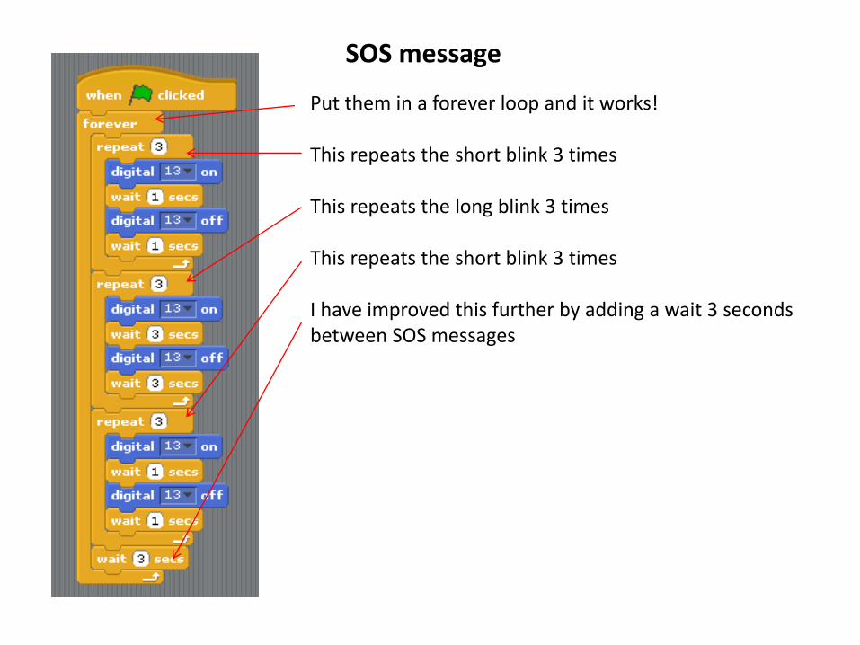
Put them in a forever loop and it works! This repeats the short blink 3 times This repeats the long blink 3 times This repeats the short blink 3 times I have improved this further by adding a wait 3 seconds between SOS messages

Challenge : Can you add a second LED to add a double blinking light?
Turning on more than 1 LED

Notice that your Arduino has another wire, a yellow wire. This joins PIN 12 to the breadboard Which holes on the breadboard does the yellow wire join to?
Turning on 2 LEDs independently

Well done. The yellow wire automatically joins to these holes on the breadboard
Turning on 2 LEDs independently

Well done. The yellow wire automatically joins to these holes on the breadboard
Turning on 2 LEDs independently

Challenge : Make a zebra crossing. Turn the RED LED ON for 1 second with the yellow LED OFF Then turn the YELLOW LED ON for 1 second with the red LED OFF
Turning on 2 LEDs independently

Creating a zebra crossing
Did you get it correct?


