16
CPE 355 - Real Time Embedded Kernels - Spring ‘12 Nuno Alves ([email protected]), College of Engineering Arduino Timers Reference: Russell Chapter 7
CPE 355 - Real Time Embedded Kernels - Spring ‘12Nuno Alves ([email protected]), College of Engineering
Arduino TimersReference: Russell Chapter 7

CPE 355 - Real Time Embedded Kernels - Spring ‘12Nuno Alves ([email protected]), College of Engineering
Timers in Arduino
• Arduino’s wiring library has many useful time related built in functions: delay(), millis() and micros() and delayMicroseconds().
• The PWM analogWrite(), the tone() and the noTone() function also uses time related function.
• Even the Servo library uses timers.

CPE 355 - Real Time Embedded Kernels - Spring ‘12Nuno Alves ([email protected]), College of Engineering
Wiring delay() function
• Pauses the program for the amount of time (in miliseconds) specified as parameter.
• There are 1000 milliseconds in a second.
• Syntax: delay(ms)
• Where ms is the number of milliseconds to pause (unsigned long).

CPE 355 - Real Time Embedded Kernels - Spring ‘12Nuno Alves ([email protected]), College of Engineering
Wiring analogWrite() function
• Function analogWrite() writes an analog value (PWM wave) to a pin.
• Can be used to light a LED at varying brightnesses or drive a motor at various speeds.

CPE 355 - Real Time Embedded Kernels - Spring ‘12Nuno Alves ([email protected]), College of Engineering
Wiring analogWrite() function
• After a call to analogWrite(), the pin will generate a steady square wave of the specified duty cycle until the next call to analogWrite().
• The frequency of the PWM signal is approximately 490 Hz.
• On the Arduino UNO, this function works on pins 3, 5, 6, 9, 10, and 11. • You do not need to call pinMode() to set the pin as an output before calling analogWrite().
• The analogWrite function has nothing whatsoever to do with the analog pins or the analogRead function.

CPE 355 - Real Time Embedded Kernels - Spring ‘12Nuno Alves ([email protected]), College of Engineering
What is a timer?
• A timer is a piece of hardware built-in the Arduino controller.
• It is like a clock, and can be used to measure time events.
• The timer can be programmed by some special registers.
• You can configure the pre-scalar for the timer, the mode of operation and many other things.
• The controller of the Arduino is the Atmel AVR ATmega328.
CPE 355 - Real Time Embedded Kernels - Spring ‘12Nuno Alves ([email protected]), College of Engineering
What is a timer?
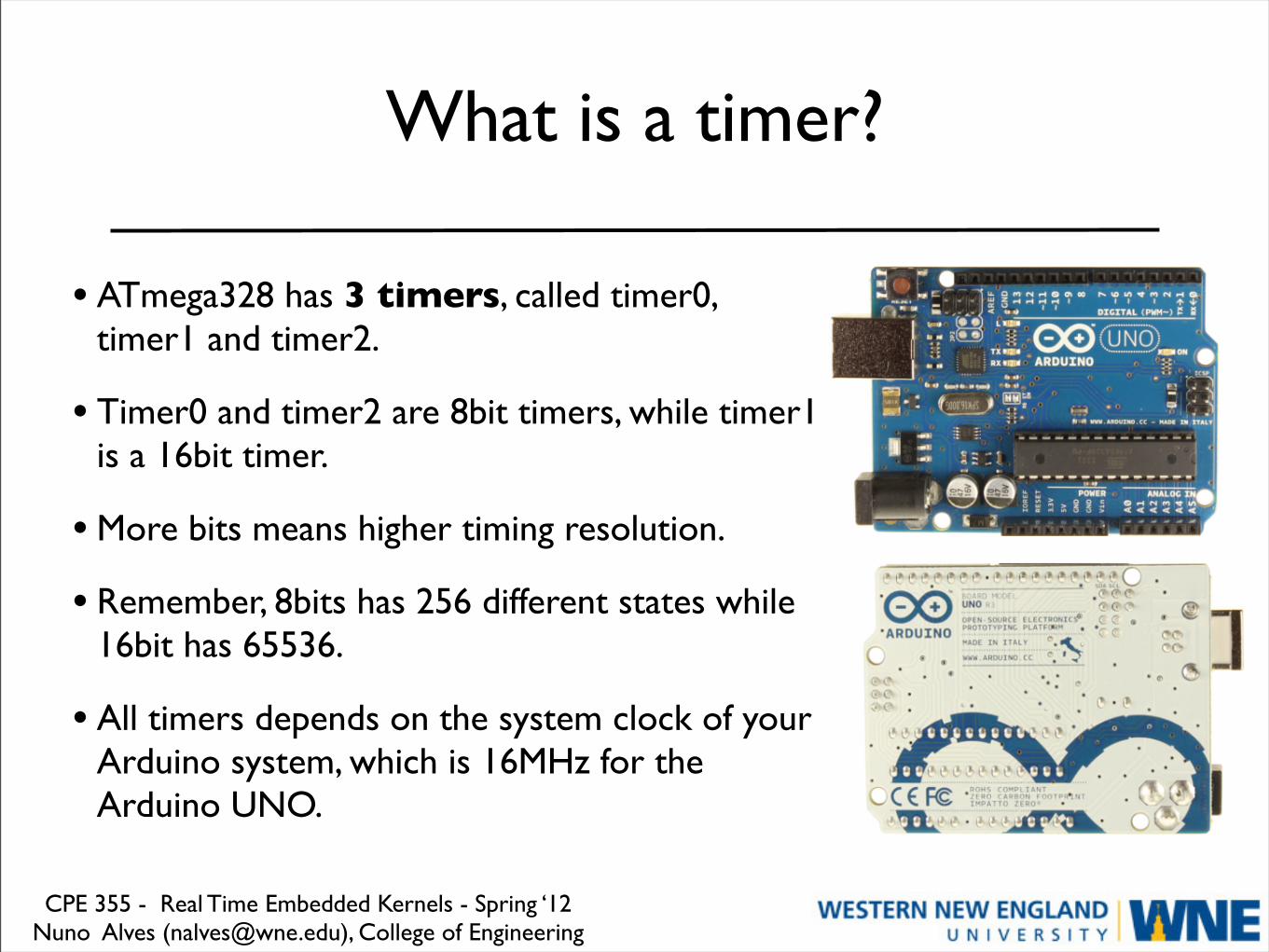
• ATmega328 has 3 timers, called timer0, timer1 and timer2.
• Timer0 and timer2 are 8bit timers, while timer1 is a 16bit timer.
• More bits means higher timing resolution.
• Remember, 8bits has 256 different states while 16bit has 65536.
• All timers depends on the system clock of your Arduino system, which is 16MHz for the Arduino UNO.

CPE 355 - Real Time Embedded Kernels - Spring ‘12Nuno Alves ([email protected]), College of Engineering
Timer0
• Timer0 is a 8bit timer.
• In the Wiring libraries, timer0 is used for the commonly used timer functions.
• You know... delay(), millis() and micros().
• Warning: If you change the timer0 registers, this may influence the Arduino timings function.
• Changes are not permanent: If accidentally mess up a timer register, just upload a new program.

CPE 355 - Real Time Embedded Kernels - Spring ‘12Nuno Alves ([email protected]), College of Engineering
Timer1
• Timer1 is a 16bit timer.
• In the Wiring libraries, this timer is used for the servo library.

CPE 355 - Real Time Embedded Kernels - Spring ‘12Nuno Alves ([email protected]), College of Engineering
Timer2
• Timer2 is a 8bit timer.
• In the Wiring libraries, this timer is used for the tone() function.
CPE 355 - Real Time Embedded Kernels - Spring ‘12Nuno Alves ([email protected]), College of Engineering
Frequency review (from wikipedia)
• Frequency is the number of occurrences of a repeating event per unit time.
• The period is the duration of one cycle in a repeating event, so the period is the reciprocal of the frequency.
• f = 1 / T
• For example, if a newborn baby's heart beats at a frequency of 120 times a minute, its period (the interval between beats) is half a second.
• Click for a neat frequency animation.

CPE 355 - Real Time Embedded Kernels - Spring ‘12Nuno Alves ([email protected]), College of Engineering
Prescaler or count-divider
A prescaler is an electronic counting circuit used to reduce a high frequency electrical signal to a lower frequency by integer division.

CPE 355 - Real Time Embedded Kernels - Spring ‘12Nuno Alves ([email protected]), College of Engineering
How to define your own timer
• In the ATmega328 there are 6 important timer registers, that can be interfaced with to adjust the Timer behavior.
• TCCRx - Timer/Counter Control Register. Prescaler is configured here.
• TCNTx - Timer/Counter Register. The actual timer value is stored here.
• OCRx - Output Compare Register
• ICRx - Input Capture Register (only for 16 bit timer)
• TIMSKx - Timer/Counter Interrupt Mask Register. To enable/disable timer interrupts.
• TIFRx - Timer/Counter Interrupt Flag Register. Indicates a pending timer interrupt.

CPE 355 - Real Time Embedded Kernels - Spring ‘12Nuno Alves ([email protected]), College of Engineering
Clock select and timer frequency
• Different clock sources can be independently selected for each timer.
• To calculate the timer frequency (e.g. 2Hz using timer1) you need:
‣CPU frequency: 16 MHz for Arduino UNO.
‣Maximum timer counter value: 256 for 8bit timer, 65536 for 16bit.
‣A prescaler value: either 256 or 1024.
‣Divide CPU frequency with a prescaler (16000000 / 256 = 62500).
‣Divide result through the desired frequency (62500 / 2Hz = 31250).
‣Verify the result against the maximum timer counter value (31250 < 65536 success). If fail, choose bigger prescaler.
CPE 355 - Real Time Embedded Kernels - Spring ‘12Nuno Alves ([email protected]), College of Engineering
Calculating the prescaler
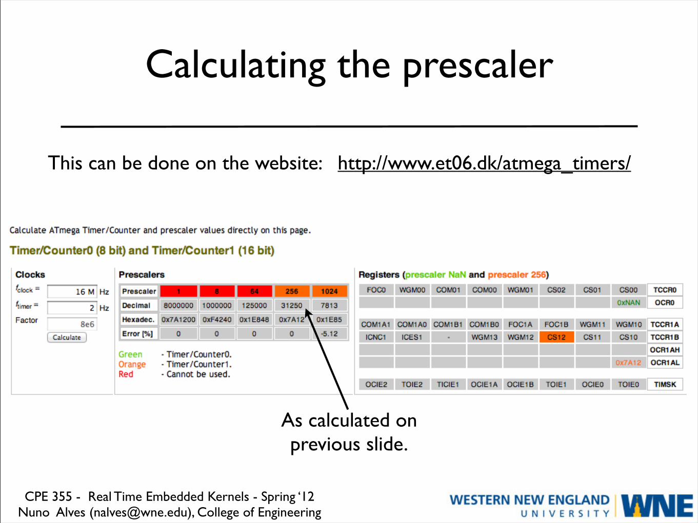
This can be done on the website: http://www.et06.dk/atmega_timers/
As calculated on previous slide.

CPE 355 - Real Time Embedded Kernels - Spring ‘12Nuno Alves ([email protected]), College of Engineering
Blinking LED with compare match interrupt
• Timer1 is in CTC mode (clear timer on compare match).
• The timer is configured for a frequency of 2Hz.
#define ledPin 13
void setup(){ pinMode(ledPin, OUTPUT); // initialize timer1 noInterrupts(); // disable all interrupts TCCR1A = 0; TCCR1B = 0; TCNT1 = 0;
//compare match register 16MHz/256/2Hz OCR1A = 31250; TCCR1B |= (1 << WGM12); // CTC mode TCCR1B |= (1 << CS12); // 256 prescaler TIMSK1 |= (1 << OCIE1A); // enable timer compare interrupt interrupts(); // enable all interrupts}
//timer compare interrupt service routine// toggle LED pinISR(TIMER1_COMPA_vect){ digitalWrite(ledPin, digitalRead(ledPin) ^ 1); }
void loop(){ // your program here...}


