134
1 file: 430txman 12-98 draft Aug. 31, 2005 Arecibo 430 MHz Radar System Operation and Maintenance Manual Written by Jon Hagen April 2001, 2nd ed. May 2005
1
file: 430txman 12-98 draft Aug. 31, 2005
Arecibo 430 MHz Radar System
Operation and Maintenance Manual
Written by Jon HagenApril 2001, 2nd ed. May 2005

2
NOTE
With its high-voltage and high-power, and high places, thistransmitter is potentially lethal. Proper precautions must betaken to avoid electrical shock, RF exposure, and X-rayexposure. (See Section 22).
Emergency Procedure: ELECTRIC SHOCK
Neutralize power 1. De-energize the circuit by means of switch or circuit breaker or cut the line by an insulatedcutter. 2. Safely remove the victim from contact with the energy source by using dry wood stick,plastic rope, leather belt, blanket or any other non-conductive materials.
Call for help 1. Others can help you administer first aid 2. Others can call professional medical help and/or arrange transfer facilities
Cardio Pulmonary Resuscitation (CPR) 1. Check victim's ABC
A - airway: Clear and open airway by head tilt - chin lift maneuver
B - breathing: Check and restore breathing by rescue breathing
C- circulation: Check and restore circulation by external chest compression
2. If pulse is present, but not breathing, maintain one rescue breathing (mouth to mouthresuscitation) as long as necessary. 3. If pulse and breathing are absent, give external chest compressions (CPR). 4. If pulse and breathing are present, stop CPR, stabilize the victim. 5. Caution: Only properly trained personnel should administer CPR to avoid further harm to

3
the victim.
Administer first aid for shock
1. Keep the victim lying down, warm and comfortable to maintain body heat until medicalassistance arrive. Don't move the victim unless absolutely necessary. Do not be in a hurry totransport the victim, more harm may be done by mishandling, jarring and shaking the victim. 2. Don't give fluid (drinks) to the victim unless necessary. 3. Keep checking the victim until medical help is obtained.

4
Table of ContentsSection 1: Introduction
1.1 Purpose and scope of this manualSection 2: Specifications.
2.1: Loss in the waveguide transmission system2.2 Increasing the bandwidth
Section 3: Brief description w/ block diagrams & picturesSection 4: Operating instructions Section 5: Litton L-3403 Klystrons
5.1Klystron frequency shiftSection 6: Final amplifier RF circuitrySection 7: Harmonic filter and EH tunerSection 8: Dummy loadSection 9: Intermediate power amplifier (IPA)Section 10: Low-power RF and pulse circuitrySection 11: High voltage power supplySection 12: Crowbar, Reflected Power Detectors, and Arc DetectorsSection 13: ModulatorSection 14: Cooling systemSection 15: Monitoring system, including waveguide receiver sample portSection 16: AC power control circuitrySection 17: Timing system (timing generator)Section 18: Receiver protection (monoplexers & drivers)Section19: Waveguide run to platform and rotary joint.Section20: Platform power divider and linear jointsSection 21: Turnstile junctionsSection 22: Safety systems & hazards: radiation, high-voltage, X-ray, ChemicalSection 23: MaintenanceSection 24: Trouble-shooting/spare parts inventorySection 25: Glossary, acronyms and abbreviationsSection 26: Overall list of schematic diagrams and other associated documentationSection 26.2: List of schematic diagrams appended to this manualSection 27: Pending ModificationsSection 28: Index

5
1. IntroductionThe 430 MHz radar transmitter at Arecibo Observatory was built in 1962 by Levinthal
Electronic Products, which became Radiation at Stanford, as original equipment for theobservatory. The project engineer was Gene E. Talmadge. The transmitter operates at a fixedcenter frequency of 430 MHz with a maximum transmitted bandwidth of 1 MHz (see Section2.1) Two Litton L-3403 or L-5773 klystrons operate in parallel as a balanced amplifier, with a90-degree power splitter at the input and a high-power 90-degree combiner at the output, toprovide a maximum total peak pulse output power of 2.5 MW. Power is delivered to the antennaplatform via 1500 feet of WR2100 waveguide. An infinitely variable power splitter on theplatform provides transmitter power to feed antennas in both the Gregorian dome (a feed horn)and the carriage house (the line feed).This allows dual beam operation, which could have beencalled “dual radar”operation, as it is equivalent to two radars pointing in different directions. Themaximum beam duty factor is 6% so the maximum average output power is 150 kW.
The limited bandwidth of the klystrons forces pulse rise and fall times to be no less thanabout 0.5 microsecond. Beam pulse lengths can be varied from 2 to 2,000 microseconds. Withinthe pulse, amplitude and/or phase modulated can be applied to the RF drive. The high powermodulating (turn on/turn off) circuitry for the klystron beam constrains the pulse repetitionfrequency (PRF) to a maximum of 1 kHz. For more closely spaced pulses, one may modulate thelow-level RF drive at frequencies up to 1 Mhz while keeping the beam current on. Note: In thismode it is still necessary to limit the beam duty factor to 6%. Moreover, the beam must alwaysbe off while receiving because klystron-produced noise leaks across the turnstile junction (T/Rdiplexer) and into the receiver.
1.1 Purpose and scope of this manual Sections 2 through 5 of this manual serve as a users' manual, updating the original
manuals and drawings and adding sections to cover the ancillary equipment: receiver protection,and related interlocks, feed line, and other platform mounted waveguide components. Theequipment and the control console are described in sufficient detail for a scientist to gainconfidence in operation of the transmitter. Sections 6 through 12 are intended for maintenanceengineers and technicians. This manual, together with a subset of the original documentation,listed in Section 25, comprise the available documentation for the 430 MHz transmitter.
2. Transmitter SpecificationsTransmitter designation: Radiation at Stanford Model PC-349Klystron type: Litton L-3403 or L-5773 (two); 10ft tall, 840 lbs, surrounded by a 2900 lb

6
solenoid magnet.Center Frequency: 430 MHz ,adjustable from 400 to 450 MHz, except for linear joint (see sec.20)Frequency stability: better than 2 parts in 1011 over periods of 1 sec to 1 hr. (determined bystation frequency standard)Phase Stability: see Section 5.1Maximum instantaneous bandwidth: 2 MHz (see next section)Maximum Peak Power at transmitter output: 2.5 kWMaximum Avg. Power at transmitter output: 150 kWMaximum beam duty factor: 6% (Originally an optional cw mode was provided, presumably
based on a cw specification for the original pair of Varian klystrons. The current Littonklystrons are specified only for pulsed operation.
Efficiency: 44% to 48%Power supply max. rating: 120,000 V @ 4.4 A (run at 90kV to 95kV for Litton L-5773klystrons).Power supply regulation: 12% no load to full loadWaveguide system attenuation: 1dBMaximum PRF: 1kHzMinimum PRF: noneMaximum pulse length: 10 2.1 msMinimum pulse length: 20 usec.Beam Current Rise and Fall time: 5 usec minimum
Power output variation: less than 0.2 dB pulse-to-pulse after 15 minutes warmupOutput pulse shape: rectangular (shaped pulses can be obtained by modulating the RF drive.Output power adjustability: continuously adjustable to -20 dB Interpulse noise: The noise contributed by the klystron beam is less than 750 Kelvins. (This is reduced appox. 30 dB to 0.75 Kelvins by the isolation in the TR turnstile junction).EIRP: the 430 transmitter supplies about 2MW peak power up to the antenna. The antenna has a62dB gain, so the EIRP is 2 x 106.2 MW = 3.2 million Megawatts peak. The average 430 MHzEIRP is 6% of the peak or 224,000 Megawatts.
Beamwidth: is given by lamda/dish diameter = .7m/300m = .0023 radians = 0.13 degrees.
Other Arecibo transmitting systems, for comparison:The S-band transmitter supplies 1MW (peak and average) to the antenna. The gain is 74dB

7
so the EIRP is 1 x 107.4 MW = 25 million Megawatts.The beamwidth of the 2380 radar system is 1.9 arc minutes or 0.032 degrees.
The 46.8 MHz transmitter supplies the antenna with 40kW peak and 2 kW average. The gainis around 37dB (assuming the yagi feed produces an aperture efficiency of 25%), so the EIRPis 40kW x 103.7 = 200,000 kW peak and 10,000 kW average.The beamwith at 46.8 MHz is 6.4/300 = .02 radians or 1.2 degrees.
2.1 Loss in the waveguide transmission system. The overall loss in the transmission system was measured directly with a signal
generator and power meter and found to be about 1 dB. This is due to the sum of the ohmiclosses in the E-H tuner, waveguide run, rotary joint, linear joint, and waveguide tuner, whichseem to total about 0.9dB, inreased to 1 dB by the presence of standing wave ratio in the lineof about 1.9:1. Thus, when the klystrons are putting out a total of 2.5MW, the power exitingthe antenna is only about 1.96 MW.
Note: the power dissipated by losses in a transmission line are the sum of thedissipations caused by the the forward wave and the reverse wave, as if they existedindependently. Therefore, if a forward wave of unit power is sent into the downstairs end ofthe waveguide, the forward power arriving at the top will be G where the ‘gain’, G, would be,for example, 0.75 if 25 percent of the forward power is lost to dissipation. If the voltagereflection coefficient at the platform end is ρ, then the power transmitted by the feed will be G(1-ρ2). The reflected power, arriving back at the downstairs end will be G2 ρ2. Therere, theoverall gain, i.e. , power transmitted / net power into the line is given by Geffective = G(1-ρ2)/(1-G2 ρ2). Example: if G= 10-0.09 (.9 db attenuation),and ρ= sqrt(1/10) ( 1.92 VSWR), then Geffective = .783 or 1.06 dB effectiive attenuation.
2.2 Increasing the BandwidthThere has long been a desire for increased bandwidth to achieve better range
resolution. In 1980, Gene E. Tallmadge, then at S.R.I., prepared a report “Arecibo 430 MHzTransmitter Enhancement Study”.The objective was to evaluate the feasibility ofmodifications so that 180 degree phase changes can be transmitted at a baud width of 0.2 µs

8
with an attendant power output reduction of 3 dB or less - using the existing klystrons ormodifying them. Tallmadge concluded that the bandwidth limitation at that time was due tothe IPA (driver amplifier) and that, by changing to a wide-band IPA and re-tuning the finalklystrons, the goal could be met. His data is shown below. Tallmadge estimated that the wide-band driver would have to supply 3.14 kW peak power. We now have a wide-band solid-stateIPA, capable of 1kW drive power. The installation of this new driver amplifier made anoticable improvement in bandwidth, but as of May, 2005,the klystrons have not been tuned for the maximum 2MHz bandwidth.
Transmitter Bandwidth Limitations as of 1980IPA was the bottleneck at that time. PA can achieve 2 MHz bandwidth.
(figure from report by Gene Talmadge)

9
3. Brief Description of the TransmitterThree block diagrams on the following pages present an overall picture of the
transmitter. 3.1 RF Circuitry - Refer to drawing 430BLOK13.1.0Timing Generator
For testing purposes, this unit in the control console can generate the four pulsesneeded to control the transmitter: the receiver protection command, the beam on command,the rf on command and the rf phase command. But normally these commands are generatedby a programmable pulse generator that is part of the computer data-taking interface. Theprogram-generated pulses enter the timing generator as “Request pulses”. Unless they violaterestrictions put on duty factor, pulse length, etc, the requests are passed on, unaltered, ascommands to the transmitter circuitry. Otherwise the timing generator modifies them to makethem acceptable. When this occurs, lights on the panel of the timing generator indicate whatrestrictions are being violated. 3.1.1 Exciter
The exciter circuitry is in the control console. Its output stage is a 20dBm amplifier.The output from this amplifier, 100mW peak, is pulsed on and off synchronously with thehigh-power modulator. The exciter can apply bi-phase modulation to the drive signal. Noamplitude modulator is included in the exciter, although the subsequent IPA and PA stagesare essentially linear amplifiers when they are not driven to saturation.
3.1.2 Intermediate Power Amplifier (IPA)The orignal IPA used a single Eimac 3KM3000LA external cavity klystron, capable of
producing a peak power of 20 kW or an average power of 1Kw. The present IPA is a solidstate amplifier capable of supplying 500W. A second identical amplifer is mounted in theIPA rack, together with hybrid combiners. The two amplifiers can be combined to supply1000W of drive, if needed when the PA (power amplifier) klystrons are stagger tuned. Thesesolid state ampliers are pulsed on, like the high voltage modulator, just ahead of the RF pulse.A second-harmonic trap (shorted stub) is located at the output of the IPA. The IPA signalreaches the PA by way of a 1.5" coaxial transmission line.

10
WAVEGUIDE
WASTER LOAD
SHORT SLOT HYBRIDPOWER COMBINER
0
0
O
O
O
90O
90O
DIRECTIONAL COUPLERS
WAVEGUIDE
1.25 MW PK
0
O
EVEN-HARMONICFILTER
0
0 180
0O O
O
DIR. COUP.
MOTORIZED LINE STRETCHER(90 DEG. NOM.)
DIR. COUP.
O90
790 WATTS PK
/2 LINE:
DIR. COUP.IPA
INTERMEDIATE PWR AMP.
KLYSTRONS: LITTON L-3403
RING HYBRID PWR. DIVIDER
50-OHM, IKW LOADDIR. COUP.
RCVR SAMPLEPORT
TIMINGGENERATOR
RF GATE 0
RF GATE2
RF GATE1
10 MHZ CW+13 dBm
100 MHZCW+13 dBm
X4FREQ.MULT.
400 MHZ BPF
EXCITER & PULSE CONTROL (IN CONTROL CONSOLE)
3-WATT AMP
430 MHZ BPF
400 MHZ
MIXER
30 MHZ
+/- 5V
X3FREQ.MULT. MIXER USED AS
PHASE MODULATORAND GATE
+5, 0, -5 V
PHASE CODE
30MHZ
430 TRANSMITTER BLOCK DIAGRAMPAGE 1 OF 6: DOWNSTAIRS RF SIGNAL PATHS

11
ROTARY JOINT
HORN
1/2 HEIGHTTURNSTILE
COLLECTOR
SLOTTED WAVEGUIDE5-SCREW TUNER
MOTORIZED VARIABLE POWER DIVIDER(CONTROLLED FROM DOWNSTAIRS)
DOME
AZIMUTH ARM ROTATION
Y SWITCH
LINE FEED
TRAVELLING COLLECTOR
WG-TO-COAXTRANSITION
RECEIVER RHC
RECEIVER LHC
WG-TO-COATRANSITIONTURNSTILE
JUNCTION
CARRIAGE HOUSE EL EVATION
SLOTTED WAVEGUIDE5-SCREW TUNER
DOME EL EVATION
2.5 MW PK
0 180
0
O O
O0O
E-H TUNER (MAGIC T)
HARMONIC FILTER(MUFFLER TYPE)
TUNING CONTROLMOTOR VOLTAGES
DIR. COUP.
DUMMY LOAD(BOLTS IN WHEN NEEDED)
WR430 WAVEGUIDETO PLATFORM
430blok1.ecw jbh 12-02-98 re
430 TRANSMITTER BLOCK DIAGRAMPAGE2 OF 6: UPSTAIRS RF SIGNAL PATHS
430 TRANSMITTERDWG 430BLOCK, p1 OF 3TITLE: BLOCK DIAGRAMDRAWN 12-98 TO REPLACE J349C003PAGE 1 OF 3: RF CIRCUITRY

12
3.1.3 Power Amplifier (PA)Two klystrons operate in parallel as a balanced amplifier with a coax power divider at
the input and a waveguide 90-degree hybrid combiner at the output. The input power divideris actually a ring hybrid and the divided outputs have the same phase. However, one of theseoutputs is delayed the necessary additional 90 degrees by a remotely adjustable motor-driventransmission line "trombone". The isolated port on the output combiner is terminated with a"waster load". Nominally there should be no power dissipated in the waster if the trombonesection is adjusted correctly but, if the two klystrons do not have identical output power, somewasted power is inevitable. If the phase is wrong by 180 degrees, all the power will bediverted to the waster instead to the antenna. Directional couplers allow the operator tomonitor the total output power, the waster power, and the individual drive and output powers.
The Litton L-3403 and L-5773 internal cavity klystrons were developed for the BMEWS(Ballistic Missile Early Warning System) air defense radar system. Hundreds of these tubeswere used at the three BMEWs sites - Thule (Greenland), Clear (Alaska), and Fylingdales(England). The L-3403 set records for reliability; many operated continuously up to ten yearsin BMEWs transmitters. The L-5733 was developed in the ‘80s as a high-efficiency variant ofthe L-3403; the efficiency went from 35% to around 45%. Arecibo has inherited surplus tubesof both types from the BMEWS stations at Thule and Clear. See Section 5 for the klystronspecifications.
The klystron beam current is modulated, i.e. turned on only for the duration of each RF drivepulse. During the pulse, 35% of the beam power (beam voltage x beam current) is convertedto useful RF output power and 65% is converted to wasted heat. The output power during thepulse is 2.5MW and the input power is 2.5/.35 = 7.14MW. The average powers are 150kWand 429 kW, respectively. When there is no RF drive, 100% of the beam power is convertedto heat. If the beam were not turned off between pulses, the input power to the transmitterwould be 7.14MW/.06 = 119MW. Pulsing the beam at a 6% RF duty factor reduces the inputpower to 429 kW, a considerable saving in power! (The klystrons, of course, cannot dissipateenough heat to run with the beam on continuously; their maximum duty factor is 6%).

13
Litton L3403Klystron cut open for display at Arecibo
Note tuning plungers with bellows vacuum seals andcooling coils wrapped around drift tube in sections between cavities.
Beam pulsing is done by means of a "mod anode" control element built into each klystron.When the mod anode is biased about halfway between the cathode and anode voltages, thebeam current is turned on. When the mod anode is biased slightly (5kV) more negative thanthe cathode voltage, the beam is completely turned off. The complete turn off is needed, evenin the absence of RF drive, to prevent the klystron from generating noise, some of whichwould leak through the turnstile junction diplexer and into the receiver. (See specifications;even with the beam ‘off’, the transmitter noise power output could be as large as 750Kelvins). The modulator for the PA is a high-power vacuum tube switching circuit thatconnects the mod anodes (which are connected in parallel) to a -55kV "half voltage" tap onthe beam power supply or to the chassis of the "buffer deck" which is at a potential 5kV morenegative than the cathodes. The modulator is described in detail in Section 13.For highvoltage insulation, a fiber optic link to the floating deck is used to turn on the beam. A secondfiber optic link, to the buffer deck, pulses the buffer deck for 2 microseconds following thebeam pulse to bring the mod anodes back down to cathode potential, turning off the beam.
3.1.4 Harmonic filter, Antenna tuner and waveguide

14
A high-power “waffle-iron” or “muffler type” waveguide filter provides dissipativeattenuation for any power at the second and higher harmonics. Like the klystrons, this filterwas developed for the BMEWS radars. the harmonic filter is followed by an antenna tuner inthe form of a waveguide magic-T hybrid with motor-driven stubs on two of its four ports. Thisso-called EH tuner (see Section 19) can be adjusted to present the transmitter with areflectionless load for any reflection coefficient appearing at the downstairs end of thewaveguide. The tuner is followed by 1500 feet of WR2100 waveguide that run from thecontrol building to the platform. When considerable EH tuner correction is needed, it isbecause there are large reflections from the platform-mounted components. Although thetuner eliminates standing waves on the transmitter side, reflections from the platform will, ofcourse, result in standing waves in the 1500 ft. run of waveguide. But, as is the case in alltransmission line situations, if the VSWR on the transmission line is less than about 2:1, thepower dissipated by ohmic loss in the line is an acceptably small fraction of the total power.
3.1.5 Platform RF componentsThe waveguide passes through a rotary joint at the top center of the azimuth arm. It thenproceeds down to the bottom of the arm to the continuously adjustable two-way powerdivider, described in Section 20. One output of the divider supplies power to the carriagehouse while the other output supplies power to the Gregorian dome. This dual-beam operationis equivalent to two radars pointing in different directions. Connections from the powerdivider to the carriage house and the dome require the equivalent of telescoping waveguidesto accommodate motion along the elevation track. This is accomplished by using a slottedwaveguide fixed to the bottom of the azimuth arm. The slot (which has negligible radiationloss) points downward. A pickup probe extends from the carriage house up into the slot. Theprobe is actually a special waveguide elbow with wheels. This "collector" travels along insidethe slotted waveguide. It has a half-height output port that passes through the approximately8" wide slot. A 5-probe tuner at the junction of the WR2100 and the slotted waveguideeliminates reflections that would be produced at this junction. Power from the collector entersthe carriage house though a length of corrugated waveguide and is connected to a turnstilejunction. The lengths of the side arm shorts on the turnstile are adjusted so that a. no power istransferred from the transmitter port to the opposite port (the receiver port) and b. that thepower leaving the antenna port has circular polarization. When the transmitted signal isreflected by a radar target (the ionosphere, the moon, etc.) the echo returns with the oppositecircular polarization. The turnstile routes this echo power to the receiver port. This turnstilejunction/circular polarization setup is therefore "self diplexing" - no additional hardware isneeded to switch the antenna back and forth between the transmitter and the receiver.

15
3.2 High Voltage Power SupplyAn adjustable power supply furnishes up to 120 kV at 4.4 amps. The voltage charges
the 37.2 uF capacitor bank. When the transmitter is pulsed, the klystrons pull high currentfrom the capacitor bank. The power supply is behind a locked door in the high voltage vault.The key that unlocks the vault door is the key that operates the power switch on thetransmitter console. The key cannot be removed from the console unless the power switch isin the Off position.
3.2.1 CrowbarThe Crowbar circuit provides path by which the nearly all the charge in the capacitor bankcan be dumped to ground, rather than through an arc inside one of the klystrons. Two faultconditions indicating an internal arc can trigger the crowbar to fire: excessive pulse length anda sudden increase in body current. (Note that body current might be called ‘ground fault’current. Besides true body current within the klystron, leakage current from any part of theB- supply to ground will be read as body current and will trigger the crowbar). The term“crowbar” was probably adopted to suggest a heavy metal bar used to produce a sudden short.

16
T005
INDUCTROLTRANSFORMER
22,000 lbs200A OILCIR. BKR
VAC. BKR.
BEAM TANK ASSEMBLY
COMMON
"IPA"
INTERMEDIATEPOWER AMPLIFIER
(KLYSTRON DRIVER)
4160V 3ph 400A
FUSE
MAINDISCONNECT BOX
SWITCHGEAR RACK
MOTORCONTROL VOLTAGE
T29(3-SINGLEP PHASETRANSFORMERS)
CB033(300A)
120VAC TO CONSOLE, COOLING SYSTEM, ETC.
LEAKAGE INDUCTANCEDESIGNED INTO TRANSFORMERSACTS AS (RECTIFIER SIDE)POWER SUPPLY CHOKE
T004
430bloc1.ecw jbh 11-30-98 rev 12-0
430 TRANSMITTER BLOCK DIAGRAMHIGH VOLTAGE CIRCUITRY P1 of 3

17
36pF
3.6M
248 x 0.15uF=37.2uF @ 120kV(268 kJOULES)
R46: 525k, 7kW
DANGER: - 110 kV
500M180 W
BLEEDERTOWER
SEE DWG 430_C105.ecw
1:14
1250
.02 uF
+50kV
4.24M500W
V801B5C22
115 VAC
(SEE DWG. 430_102.ecw)
B+ BUS ("NEAR GROUND")
B- BUS -55 kV NOM.
ZENER TOWER
R8610k4kW
C87: 11.4uF10kV
R471k 200W
R84100 400W
C370.5uF55kV
25200W
HV CIRCUITRYBETWEEN CORONARINGS ABOVE CAPBANK
(SEE DWG430_C105.ecw)
CAPACITOR BANK
CROWBAR
CROWBAR COMMAND
430bloc1.ecw jbh 11-30-98 rev 12
430 TRANSMITTER BLOCK DIAGRAMHIGH VOLTAGE CIRCUITRY P2 of 3

18
TO CROWBARTRIGGER GEN.
CATHODE LITTON L-3403KLYSTRONS
2.5 OHM, 480 W
0.67 OHM, 1kW1 uF
.0055 OHM TO "BEAM CURRENT" CONSOLE METER
TO "KLY B COLLECTOR CURRENT" CONSOLE METER
HV BUSHING
+
EARTH GROUND
EARTH GROUND
HV BUSHING
FIBER
FIBER
BEAM START COMMAND
BEAM STOP COMMAND
COLLECTOR
MOD ANODE
5KV BIAS SUPPLY
BUFFER DECK
(TURNS BEAM OFF)
FLOATING DECK
(TURNS BEAM ON)
BEAM MAGNET
BEAM MAGNETPWR SUPPLY RACK
16 BEAM MAGNETS (8 FOR EACH KLYSTRON)
AC POWER FROM VARIACS ON CONSOLE
SHIELDED ANODE WIRES RUNACROSS FLOOR TO KLYSTRON VAULT
"KLY B COLLECTOR CURRENT" TO CONSOLE SCOPE
"PULSE LENGTH" TO CROWBAR TRIGGER GEN.
METER SHUNT FRAME ON FLOOR AT END OF CAP BANK RACK
V301 (SWITCH TUBE)
V401 (TAIL CLIPPER)
CURRENT-LIMITING RESISTOR/FUSENICROME WIRE IN TIGHT COILS
EACH 150 OHM, 12 KW
MODULATOROVERCURRENTRELAY COIL
MODULATOR(SEE DWG 430_112.ecw)
0.16 OHMSBODY CURRENTMETER SHUNT
BEAM MAGNET
BEAM MAGNET
HV METERING TOWER
R4300 M, 300W
R22,R23EACH 22k, 2W
TO "BEAM VOLTAGE"CONSOLE METER
L93.4 uH
430bloc1.ecw jbh 11-30-98 rev
430 TRANSMITTER BLOCK DIAGRAHIGH VOLTAGE CIRCUITRY P3 of 3

19
KLYSTRON B BODY
7.5 GPM
O C TEMPERATURESENSOR
FLOWSENSOR
KLYSTRON ACOOLING CIRCUITS
KLYSTRON ACOOLING CIRCUITS
FLOW
FLOW
VL901 VL904 VL907 VL902 VL905 VL909
TEMPERATURESWITCH
TEMPERATURESWITCH
KLYSTRON B MAGNET
7.5 GPM
KLYSTRON B TUNER
2 GPM
KLYSTRON B BODY
7.5 GPM
KLYSTRON BCOLLECTOR
50 GPM
FLOWMETER &INTERLOCK
FLOWINTER-LOCK
FLOWMETER &INTERLOCK
FLOWINTER-LOCK
M901
S901
M902
M903 M904S902 S904S903
KLYSTRON ACOLLECTOR
50 GPM
KLYSTRON A BODY
7.5 GPM
KLYSTRON A TUNER
2 GPM
KLYSTRON A MAGNET
7.5 GPM
S906 S907 S908 S909 S910 S911 S912 S913
430 TRANSMITTER BLOCK DIAGRAMCOOLING SYSTEM PAGE 1 OF 2
S917CLOSED WHENPRESSURE LOW
K901C
K901
S924CLOSED WHENFLOW IS ADEQUATE
VL960
S925CLOSED WHENFLOW IS ADEQUATE
K902A K902B
S916CLOSED WHENPRESSURE LOW
K901A K901B
TIME DELAY RELAY(DELAYED TURN-ONLETS FLOW GETSTARTED)
K902
DUMMY LOADSOLENOID VALVE
VL961
WASTER LOADSOLENOID VALVE
120VAC FROMCB31 ON CONSOLE
NORMALLY CLOSEDRESET BUTTON ONCONSOLE: S5/1B
K901CLATCHES FAULT
SOLENOID VALVE ELECTRICAL CIRCUITRY
3.3 Cooling system: The cooling system is shown below in block diagram form

20
430 TRANSMITTERDRAWING 430BLOCKTITLE: BLOCK DIAGRAMDRAWN 11-98 TO REPLACE J349C003PAGE 3 OF 3: COOLING SYTEM
TEMPERATURE GAUGE
RADIATOR: 660 KW (37,567 BTU/MIN)91,200 SCFM
AMBIENT: TO 110 DEG. F
FLOWBOOSTER PUMP
CHECK VALVE
VL961
SOLENOID VALVE
VL911
VL912
PUMP HOUSE
MAIN PUMP
VL97
VL97
S917CLOSED WHENPRESSURE LOW
VL959PRESS. SW
O C
MODULATORTANK
FLOWSENSOR
TEMPERATURESENSOR
BYPASS
VL960
SOLENOID VALVE
VL963
PRESSURE GAUGEM912
PRESS. SWVL958 S916
CLOSED WHENPRESSURE LOW
PRESSURE GAUGEML909
VL934
S925CLOSED WHENFLOW IS ADEQUATE
S924CLOSED WHENFLOW IS ADEQUATE
VL966RELIEF VL965
RELIEF
O C TEMPERATURESENSOR
O C TEMPERATURESENSOR
WASTER LOAD
25 GPM
DUMMY LOAD
25 GPM ML911ML910
VL933
PRESSURE GAUGEML908
SOLENOID VALVESCLOSE TO PREVENTCOOLANT LOSS IF DUMMY OR WASTERLOADF RUPTURES
430 TRANSMITTER BLOCK DIAGRAM COOLING SYSTEM PAGE 2 OF 2
= FLOW METERAND FLOWINTERLOCK
INTERLOCKCHAINSWITCH
FLOW METER/INTERLOCK DETAIL
SEE ORIGINAL DWG D-3
430bloc1.ecw jbh 12-02-98

21
430 TRANSMITTERDRAWING 430BLOC1TITLE: BLOCK DIAGRAMDRAWN 11-98 TO REPLACE J349C003PAGE 4 OF 4: HEAT EXCHANGER
430bloc1.ecw jbh 12-02-98rev. 2-24-03 jbh
PRESS. RELEASEVALVE
MAIN PUMP
DRAIN
660 KW (37,567 BTU/MIN)91,200 SCFM
RADIATOR PANEL
RADIATOR PANEL
TANK
1/4" COPPER TUBING
N.O. N.O.
N.O. N.O.
NC NC
NC
DIVERTER
HEAT EXCHANGERON OUTDOOR PAD
200 GAL.STAINLESSSTEELTANK
DISTILLER
WATER MAIN
110VAC
120VAC
3/4HP UTILITY PUMPGARDEN HOSEGARDEN HOSE
FILL UNTIL WATER SPILLS FROMSTORAGE TANK
WATER STORAGE TANKAPPROX 25 FT OFF THE GROUND

22
Water storage tank on side ofbuilding. Note the waveguide,leaving the EH tuner on themezzanine and heading down toloop beneath the road.
Heat exchanger on pad next to oil storage tanks.

23
3.4 Modification HistoryDuring the original installation of the transmitter, the crowbar circuit was redesigned
(though the original manual was not updated). The Marx Generator (voltage multiplier) thatsupplied the crowbar ignition voltage was eliminated. A sharp point was substituted for theignition ball. A resistor voltage divider was used to bias this point at half the beam supplyvoltage. Later this divider was eliminated and the point was biased from the halfway tap (-55kV nom.) of the beam supply.
In 1972, the vacuum tube HV rectifiers were replaced with silicon rectifier stacks.Filament transformers and regulators for the tube rectifiers were removed.
In 1985, circuitry was installed to limit further the initial inrush current in the klystronfilaments. This consists of a choke in series with the primary of the filament transformer. Atime delay relay shorts the choke after the delay.
In 1986, the original bank of capacitors was replaced with new non-PCB capacitors.While the original capacitor bank could be strapped in two configurations (110kV and 150kV,the new bank has a fixed configuration: 120kV max. The low-level RF and pulse circuits haveevolved throughout the life of the transmitter.
In 2002, the buffer deck fiber optic control was simplified. A fixed 10 usec pulse issent to the buffer deck after the floating deck is turned off. Before, identical command pulseswere sent to each deck. The buffer deck turned itself on when the pulse was off AND thevoltage of the floating deck was sensed to be high. Any accidental interruption of the link tothe buffer deck would cause shoot-through (both decks on simultaneously).This modificationalso eliminated the need for the troublesome high voltage divider needed for the buffer deckto sense the floating deck potential.
In 2005, a second fiber was provided to each deck. These fibers directly operate theclamp tubes that prevent ‘shoot through’, simultaneous conduction in the pull up tube(floating deck switch tube) and the pull down switch tube. Originally, each clamp tube wasoperated automatically froma signal derived on its respective deck. Both decks had to be operating to produce theclamping action. With the externally supplied fibers, the decks can be operated independentlyfor easier testing and troubleshooting. The original clamp circuits were OR’d with the newfiber signals, to provide back-ups for the fibers.

24
4. Operating InstructionsThe transmitter operation is very simple. The only tuning needed during the turn-on
sequence is adjustment of the waveguide tuner in order to minimize the reflected waves seenby the klystrons.
4.2 Turn-on sequence1. Push the IPA SYSTEM ON button. The green IPA SYSTEM ON indicator lamp above thisbutton should light. (Note, as of May 2005, the new IPA must still be turned on at its rack inthe transmitter room).
2. Push the PA SYSTEM ON button. The green PA SYSTEM ON indicator lamp above thisbutton should light. A series of relays should be heard as they are energized. The rows of neonlights at the left hand lower apron of the console should start lighting and the magnet currentmeters should show current.
3. Fifteen minutes after pushing the PA SYSTEM ON button, the orange PA HV READYindicator lamp will come on telling the operator that the transmitter is ready for operation. Setthe SCOPE OUTPUT selector to MOD ANODE and push the PA RESET button. A squarepulse should be seen on the scope.
4. Push the PA HIGH VOLTAGE ON button. The red PA HIGH VOLTAGE ON indicator lampwill light. Use the PA RAISE LOWER lever to raise the PA voltage to the value required: 98kV for 2.5 MW of RF output power.
5. The motorized E-H tuner can be used to minimize the power reflected back to thetransmitter.Operate the two (interactive) controls to minimize the reflected power reading on thebolometer.

25
Face view of control console
Close-up of console center section

26
NORM: OUTPUT FREQUENCY = "10 MHz" (FROM J13 ON REAR PANEL) X 3 + 4 X "100 MHz" (FROM J2 ON LOW LEV. AMP REAR PANEL)
STEPPED: OUTPUT FREQUENCY ="30 MHz" (FROM J11 ON REAR PANEL)+ 4 X "100 MHz" (FROM J2 ON LOW LEV. AMP REAR PANEL)
+15
LOW LEVEL AMPLIFIERCOARSE GAIN
01
23
4 5 67
89
10db
USED TO SET DRIVELEVEL TO IPA.
MOD 30 100 400 430
TEST OUTPUTS
NOTE: NORMAL SWITCH SETTINGS SHOWN IN BOLD
EXTERNAL (STEPPED)
FREQUENCYINTERNAL (430 FIXED)
S1
+5 -5 +15 -15
J1810 MHZ
J1930 MHZ
J20MOD
LOW LEVEL RF MODULATOR LOW OUTPUT POWER ALARM
SONALERTLED1
ON
SILENT
S6
TEST POINTS
ALARM TO AWAKEN OPERATORWHEN TRANSMITTER OUTPUT POWER IS LOW
file: lowlevel.ecw jbh 9-16-02, 8-29-03

27
Modulator disable:small slide switch at the right
of the modulator high voltage supply meter
Door open on right-hand side of control console to show interior meters
5.01 Litton L-3403 KlystronsFrom the Litton Installation and Operation Manual:"The L-3403 Klystron is a four-cavity, modulating-anode, pulsed klystron amplifier whichcan be mechanically tuned to amply any frequency within the range from 400 to 450 MHz.The tube will produce a peak power output of 1.25 MW at an average RF power output of 75

28
kW at a 0.06 duty factor with a minimum power gain of 35 dB. The efficiency of the tube is35%, so 75kW output power requires 223kW of beam power. When the proper voltages areapplied to the tube, a beam of electrons is formed at the cathode end of the tube and travelsaxially through the tube to the collector. The beam is maintained in its cylindrical shape by anaxial magnetic field produced by eight external electromagnets. The beam passes through fourinternal cavity resonators. With RF power applied to the input cavity, and with the fourcavities tuned properly, the amplified signal is available at a coaxial output connector. Afterthe electrons pass through the cavities, they impinge on the inner surface of the collector andthe remaining beam energy is converted to heat with is carried away by the liquid coolant.
The tubes are 10 feet long with a principal diameter of 17.5 inches. They weighapproximately 885 pounds. The coolant flows are 50 gpm for the collector, 7 gpm for thebody, and 1 gpm for the tuners. At these flow rates the pressure drop across any of the threecooling circuits should not exceed 50 psi. Maximum inlet pressure should never exceed100psi and the temperature at the outlet must be not exceed 70 deg. C, which ever is less. Thecircuits should not be operated in series. Air cooling of the coaxial output horn is required toprevent overheating the metal-to-ceramic seals. Approximately 20 cfm is sufficient.
The heater requires a voltage of 30 volts and can be either dc or ac since the cathode isindirectly heated. At 30 volts the current should be between 12A and 15A. Since the coldheater resistance is 0.20 ohms, some provision must be made to prevent a turn-on surge fromexceeding the maximum limit of 22.5A.
High voltage should not be applied unless the vacuum is better than 5 x 10⁻⁶ mmHg.The mod anode is the beam current control electrode, used for beam pulsing. Full beam poweris obtained with the mod anode is at approximately midway between the anode and cathodevoltages The mod anode must never exceed 60% of the anode-to-cathode voltage.
The tube is designed to operate with a peak input beam power of 4.01 MW. With thisinput power, the tube is designed to operate with a maximum cathode pulse length of 2.1 msat a PRF of 30 Hz. The start of the RF drive pulse should coincide with the flat portion ofthe dc pulse, i.e.
when the beam is fully on. Refer to the Litton Industries L-3403 Klystron Installation and Operation Manual for completedetails. Appendix B from that manual is copied below:

29
5.02 Litton 5773 KlystronsThe L-5773 is an improved L-3403, designed for higher efficiency. All our L-5773s wereobtained surplus from the decommisioned BMEWS transmitters at the Clear, Alaska Air Station.We have several copies of the original Litton Installation and Operation Manual for the L-3403,but the only documentation we have on the L-5773 is some acceptance test data. That data, fromserial no. 0046, 11/8/2000, is copied below, and is quite complete. The first set of data was for
From Litton Manual, Appendix B L-3403 Klystron Maximum Operating Values
1. Filamenta. Surge Current 22.5 amperes (max)b. Heat Time 15 minutes (min)c. Voltage (operating) 30 volts (adjust)d. Current (operating) 12 to 15 amperese. Power (at tube) 450 watts (max)
2. Anode Voltage (Eb) 120 kilovolts (max)
3. Cathode Current 27 amperes (max)
4. Mod-anode Voltage Not to exceed 60% EbNominal50% Eb
5. Pulse Width 2.1 milliseconds (max)PRF 60 max. (See Note 1)Beam Duty Factor 6% (max)
6. Coolant - Distilled Water
a. Collector Flow 50 gpm (min)b. Body Flow 7 gpm (min)c. Tuner Flow 1 gpmd. Output Transition Air Flow 250 cfm (min)e. Hydraulic Pressure 50 psi drop
100 psi max.
f. Output Horn 20 cfm approx.g. Electromagnet - (See Note 2 below)
7. Focus Coil Settings
8. R.F. Drive Levela. Average 24 watts (max)b. Pulse Peak 400 watts (max)
9. Body Current .250 amperes (max)
Note 1 - PRF X pulse width not to exceed maximum duty cycle of 6% 2 - Determine flow from Electromagnet instructions

30
maximum power operation . The second set of data is for 80% of maximum rated power andreduced duty cycle, which was the mode of operation used at the BMEWS stations.
Maximum Power Tests 445 MHzFlow rates for 50psi differential pressure:
Collector: 50 GPM (50 min), Body: 8.1 GPM (7 min) Tuner: 6.0 GPM (1 GPM min)
Hydrostatic test @ 100 PSI: no leaks Collector-to-body body resistance: 1k MegohmsTemperature, Top of RF outbox coax, 1" from body 37 deg. C (180 deg. C max)Emission ∆Ik: 0.5 (10% Max)?Filament voltage 17 VoltsFilament current 13.3 AmpsHeater power 17 x 13.3 - 359W (405 W max)Focus Coil Currents (2-7.5A)
#1: 1A; #2,3,4: 5.0A; #5: 4.8A; #6: 6.0A; #7: 4.0A; #8: 6.0A
Beam pulse length 2100usec (maximum allowed)PRF 30Hz (60Hz max) [? No such limit was specified for the L-3404. We often run a 1kHzPRF.]Duty factor: 6%RF input pulse length 2000usec (maximum allowed)Anode voltage 95kV (maximum rated anode voltage is 98kV)Mod anode voltage 48.5kV= 51% anode voltage (nominally 50% of anode voltage; 60% max)Cathode current 2.02A (2.4A max) RF input power 41.7W pk (400W pk max)RF output power 1.39 MW pkGain: 45.2dB (35 dB min)Efficiency: 47.8% (40% min) Mod Anode current 2.5mA (12MA max) (must mean Modulator Supply Current) Body current (Avg) 164mA (500mA max)
80% Maximum Power Tests 445 MHz (BMEWS operating parameters)Beam pulse length 2100usec (maximum allowed)PRF 27Hz (60Hz max) [? No such limit was specified for the L-3404. We often run a 1kHz PRF.]

31
Duty factor 5.4%RF input pulse length 2000usec (maximum allowed)Anode voltage 90kV (maximum rated anode voltage is 98kV)Mod anode voltage 46.8kV= 52% anode voltage (nominally 50% of anode voltage; 60% max)Cathode current 1.71A (2.4A max) RF input power 49.2W pk (400W pk max)RF output power 1.15 MW pkGain: 43.7dB (35 dB min)Efficiency: 44.38% (40% min) Mod Anode current 2.5mA (12MA max)Body current (Avg) 127mA (500mA max)
5.1 Klystron Frequency ShiftWhen the 430 MHz transmitter is used to make Doppler velocity measurements, a correction mustbe added to the apparent Doppler shift because the output frequency of the klystron amplifier isslightly lower than input frequency (430 MHz). This is a result of the beam velocity modulationused in the klystron and the droop in accelerating voltage that occurs as the capacitor bank isdischarged. We can calculate the frequency shift as follows:
Suppose that a concentration of electrons leaves the input cavity at time t1. Its time-of-arrival at the output cavity will be t1+D/v, where D is the length of the drift tube (about 2m) and vis the electron velocity (about c/2). One period later, at t1+1/430E6, the next concentration ofelectrons leaves the input cavity. Its time of arrival will be t1+1/430E6 + D/(v+∆v) where ∆v isthe amount the beam velocity has changed in one period. The error in arrival times (w.r.t.430MHz) is given by ∆tarrival = D/(v+∆v)- D/v . - D∆v/v2.
The frequency error is given in terms of this arrival time error by
∆f/f = -∆tarrival/(1/f) = -f ∆tarrival.
Therefore we can write ∆f = -f 2 ∆tarrival = f 2 D∆v/v2.
Since mv2/2 = qE, where E is the accelerating voltage, we have ∆v/v= ∆E/2E and
∆f = f 2 D∆E/(2Ev).

32
v'c 1& 511,000E%511,000
2
The voltage change in one cycle, ∆E, is given by -I(1/f)/CPS where CPS is the value of the capacitorbank, 37µF, and I is the beam current. If we assume the output power is 2.5MW, the efficiency is35%, and the power supply voltage is 100,000, the current is given byI= 2.5@ 106 /(0.35 @ 100,000) = 71A. Therefore ∆E = -71(1/ 430@106 )/37@ 10-6 = -.0045.
Since the electron total energy is given by m0c2/%(1-v2/c2) and m0c2 = .511Mev, the velocity can bewritten as
When the voltage is 100,000, the velocity is v= .55c = .55 @ 3 @ 108 m/s.Using these values for ∆E and v, we find that
∆f = - (430@106)2 @[email protected]/(2@100,000 @.55 @ 3@108) = 50.4 Hz
This corresponds to a Doppler velocity of
vDOPPLER = c ∆f/(2f) = 50.4(3@108)/(2@430@106) = 17.6 m/s

33
6. Final amplifier RF circuitryThe detailed circuit diagram for the RF connections in final amplifier is found on page 2 ofDrawing No. 430_107, the monitoring schematic. The final amplifier consists of an input powersplitter which supplies drive power to the two klystrons and an output power combiner, awaveguide sidewall coupler made by MDL. This output combiner is a 4-port hybrid junction. Theklystrons feed two of the ports. The third port is connected to the antenna, via a tuner and about1500 ft. of WR2100 waveguide. The fourth port is connected to a load, the waster load.Assuming that the waster load presents no reflection and that the tuner has been adjusted toremove any reflection at the antenna port, each klystron will look into a matched termination, nomatter how the other klystron is tuned. This is the essential advantage of using a hybrid combiner;it allows the tubes to run in “parallel” without any mutual interaction.
When the relative phases of the klystron output waves are correct and the amplitudes are equal,all the power is sent to the antenna and no power is dissipated in the waster load. Thisrequirement is not strict. If, for example, one klystron puts out twice as much power as the other(ratio of the amplitudes is .707) and the phase error is 20 degrees, 94% of the total power reachesthe antenna and only 6% is dissipated in the waster load. Of this 6%, half is due to the phase errorand half is due to the amplitude error. Note however, that if the phase error approaches 180degrees, the power will be sent to the waster load rather than to the antenna. (This allows thewaster to be used as a dummy load; one merely changes relative drive phases by 180 degrees).
The input power divider is also a hybrid junction; if there is no reflection from the driveramplifier (IPA) and no reflection from the small waster load on the input hybrid, any powerreflected at the input of either klystron will never reach the input of the other klystron. As withthe output circuit, the hybrid isolated the klystrons from each other so that there will be nointeraction when the input cavities are tuned.
Both the input and output hybrids are 90-degree hybrids (quadrature hybrids), so the relativephases at the klystron inputs and outputs is nominally 90 degrees. The use of 90-degree hybrids,rather than 0 or 180 degree hybrids, has the advantage that the driver sees a reflectionless load,even if the klystron inputs are reflective, assuming that the klystrons have identical reflectioncoefficients. (This is also true at the output side; any wave reflected from the platform back downto the transmitter will be dissipated in the output waster load. However, the EH tuner between theoutput hybrid and the transmission line is adjusted so that no reflection arrives back at the outputhybrid).

34
Lead walled vault contains the two klystrons. The access door is open. Input splitter (ring
hybrid) is partly visible at the bottom left of thedoor behind its waster load. Above the waster loadis the motor driven trombone section used toadjust the relative phases of the klystron drivesignals.
Waveguide hybrid output combiner fed bycorrugated waveguide sections from the topof the klystron vault. The coaxial output ofthe klystrons is converted immediately towaveguide.

35
The input hybrid is actually a 180 degree hybrid (a coaxial “rat race”), but an extra 90-degreelength coax at one of its outputs makes it effectively a 90-degree hybrid. This extra length isadjustable, a motorized trombone section. From the transmitter console this phase is fine tuned tominimize the power dissipated in the waster load. This adjustment allows compensation for phaseerror in the input and output hybrids and for relative phase shift between the klystrons due to non-identical tuning or operating conditions. The spring-loaded switch to shorten/lengthen thetrombone is located at the transmitter console on the panel under the oscilloscope.
Both klystrons have four mechanically-tuned resonant cavities. All eight cavities are fitted withremotely-controlled tuning motors. The control levers for these motors are next to the tromboneadjustment lever. They are normally covered by a metal box, as they are adjusted only when aklystron is replaced. Raise these paddle switches to increase the cavity resonant frequencies.Lower these paddle switches to decrease the cavity frequencies.
Meters on the console display reflected power at the input and outputs of each klystron, atthe waster load, and at the output of the output combiner. These meters all use diode detectorsmounted on directional couplers in the waveguides.
Other console meters indicate the beam current in each klystron, the total beam current, the totalbody current, the beam voltage, and the voltage tap for the modulator (approximately half thebeam voltage).
90-degree Hybrid Output Combiner

36
7. Harmonic FilterThe waveguide filter on the mezzanine absorbs second-harmonic energy. It is known as a “leakywall” or “muffler” filter, and was designed and built by General Electric, primarily for theBMEWS radars, which used a Section 1 Filter in series with a Section 2 Filter. We have only aSection 1 unit, the 2nd harmonic absorber. (Section 2 absorbs the 3rd and 4th harmonics). Thisfilter consists of a length of WR211 waveguide whose four walls have slotted openings, too shortfor 430 MHz leakage, but long enough to pass 860 MHz. Tapered absorbing structures (asbestoscement with a conductive coating) do the absorption. Aluminum boxes support and protect theabsorbers and give the filter its cruciform cross-section. See the original General Electric manualfor more information, as well as a GE reprint “Harmonic Suppression by leaky Wall WaveguideFilter” by Vernon G. Price, Richard H. Stone, and Viktor Met. This paper includes an extensivebibliography.
Second-harmonic filter, on the mezzanine, following the output combiner. The output of the filter (right sidein the photo) feeds the EH tuner, a magic-T hybrid with motorized shorts in two of its four arms.

37
MOTOR-DRIVENSHORTSEH TUNER
(MAGIC T)
PORT 1 PORT 2
PORT 3
PORT 4
WAVEGUIDETO PLATFORM
WAVEGUIDE FROMTRANSMITTER
7.1 Antenna TunerVarious mismatches in the platform-mounted waveguide circuitry produce a reflected wave whichmakes its way down the 1500-ft waveguide to the transmitter room. To protect the transmitterfrom this reflected wave, an antenna tuner is installed at the output of the transmitter. This “EH”tuner is a magic T hybrid, a 4-port microwave junction, as shown below in Figure 1. Motor-driven shorts are installed in Ports 3 and 4. The position of these shorts can be adjusted byoperating joy stick switches at the transmitter console.
Figure 1 EH Tuner
It is interesting to see that this device is capable of presenting the transmitter with a perfectlymatched load for any reflection coefficient appearing at the end of the waveguide. Figure 2 is acircuit diagram of the tuner, showing the four ports and the voltage transmission coefficients onthe paths between these ports. Γ is the reflection coefficient at the end of the waveguide and ρ isthe reflection coefficient seen by the transmitter.

38
PORT 4
PORT 2
1 exp( jb )
PORT 3
PORT 1
x exp( ja )x
y
1 12
2
2( x exp(ja ) - exp( jb )) ( x exp( ja) + exp( jb ))
( x exp( ja ) + exp( jb ))
2
2
2
2
Figure 2 Circuit Diagram
The figure contains the essentials of the analysis. At each port, arrows show the direction of theincoming and outgoing waves. The amplitudes shown for these waves are derived as follows.
We can begin be assuming, arbitrarily, that the wave exiting Port 3 has an amplitude of 1 + j0.This choice will determine all the amplitudes, including y, the amplitude of the incident wave fromthe transmitter. The short on this port causes a total reflection, so the amplitude of the wave reflectedback into Port 3 can be written as ejb , where b is determined by the position of the short.
The wave leaving Port 4 is still unknown. We denote its amplitude as x. Likewise, we will denotethe amplitude of the incident wave from the transmitter as y. The amplitude of the wave reflectedback into Port 4 is therefore xeja , where a is determined by the position of the short on Port 4.
From the figure, we see that wave leaving Port 2 is just 2-1/2 times the sum of the waves enteringPorts 3 and 4. This figure is indicated on the figure, together with Gamma times this sum, which isthe wave reflected back into Port 2.
The waves incident on Ports 3 and 4 determine the wave leaving Port 2, as shown on the figure.The wave incident on Port 2 is just the outgoing wave, multiplied by Γ. By inspection, we can nowwrite expressions for the wave leaving Ports 4 and 3.
x 'y2%
Γ2
(xe ja%e jb) 1)

39
1 ' &y2%
Γ2
(xe ja%e jb) 2)
Adding Equations 1 and 2, y is eliminated, leaving
x%1 ' Γ (xe ja%e jb) . 3)
Solving Equation 3) for x, we find
x 'Γe jb&11&Γe ja
. 4)
From the figure, we see that, in terms x, the wave leaving Port 1, i.e. the wave reflected back to thetransmitter is given by
ρ ' x e ja
2&
e jb
2. 5)
Substituting Equation 4 to eliminate x, we find
ρ 'e ja(Γe jb&1) % e jb(Γe ja&1)
1&Γe ja. 6)
If the tuner is to make ρ = 0, the numerator of Equation 6 must vanish. This gives us
e &ja
2%
e &jb
2' Γ. 7)
The phasors on the left-hand side of Equation 7 have magnitude 1/2. The maximum magnitude of Γ isunity. It is easy to see that any Γ can be flanked by the pair of phasors in a way that satisfies Equation

40
exp( -ja )
exp( -jb )
|Γ | ' 1% cos(b&a)2
. 8)
7. See Figure 3, below.
Figure 3 Canceling Γ
Note that Equation 7 allows us to measure Γ by simply measuring a and b, the round-tripphase paths in the two shorting arms of the tuner. By fitting scales to the shorting arms, we could reada and b. To set the scales, we could simply disconnect the waveguide and substitute a shorting plate.Then a network analyzer would be placed at the transmitter side and the shorts adjusted to eliminateany reflection. At these positions, a and b must be π. The rate of change, in radians per inch, wouldbe 4π/λg , where λg, the guide wavelength at 430 MHz, is 36.265". (The factor of 4 rather than 2 isbecause the round trip distance to the short changes by two inches when the short moves one inch).Remote readouts at the transmitter console would make the calibrated tuner even more useful. Afternoting the values of a and b, the magnitude of Γ would be calculated from
8. Dummy LoadThe transmitter is equippedwith a water-cooled dummy load. This load, on the mezzanine near the waveguide power combiner,can be rolled into place and bolted to the output of the combiner, after first removing the waveguideelbow that normally connects the combiner to the harmonic filter. The load can be used to makecalorimetric measurements of the average output power, as it is equipped with a flow meter and hasthermometers at its input and output. The dissipative element in the load is the water itself. The loadis in series with the rest of the transmitter’s water circuitry. To use the load, sodium nitrite, NaNO2,isadded to the cooling water to produce a resistivity of about 8000 ohm cm (125µS/cm) at 57 deg C.This resistivity is quite temperature dependent; if the water temperature falls from 57 deg. C to 50

41
deg C(134F to 122F), the resistivity increases from 8000 ohm cm to9000 ohm cm. It has been standard practice, over the years, to run thecooling system with only distilled water (no salt), under theassumption that any foreign substance is undesirable for the system.As a result, the power combiner’s waster load, which is identical to thedummy load, has undesirably high reflectivity. However,sodium nitrite is used in Navy boilers as a rust preventative,and the concentration required here is extremely low. (Tap water inthe operations building measures about 350 µS/cm).In bulk, the salt ispoisonous, but the dilute solution should be quite safe.(Sodiumnitrite is added to sausages to preserve the red color of the meat).If wedecide to maintain the proper salt solution in the system, we should determine the correspondingvalue of the conductivity at room temperature, to facilitate measurement of the concentration whenthe system is not running.
Solution conductivity at 80 deg. F: ________ µS/cm
9. New Intermediate Power Amplifier (IPA)The original IPA (described in the old text, below) was replaced in March, 2004 by a pair of
solid state amplifiers. Each amplifier can provide 500W at a duty factor of up to 10%. Theseamplifiers were made by Wavesat Inc., Model No. WPA-042044-57-47-P, as prototypes for a phasedarray. They were furnished to Arecibo by SRI. A controller was built for these units to provide thenecessary gating (same as the the PA modulator pulse) and to allow selection of either or bothamplifiers. A single amplifier is capable of producing full output when the final klystrons are tunednormally. However, if the tubes are detuned for greater bandwidth, the IPA amps can be usedtogether, with a ring branch-line hybrid combiner. The amplifiers are flat from 420 to 440 MHz withan efficiency of about 38% Pulse rise and fall times are about 0.2usec. Gain is about 50 dB.
New IPADual 500W Solid-State AmpsMarch, 2004

42
Old Intermediate Power Amplifier (IPA) (historic note)This driver amplifier was the transmitter’s bandwidth bottle neck (1 MHz BW). It was also the
most reliable section of the transmitter, consisting of a single klystron which runs as a cw class-Aamplifier. This tube was a “beam stick”; it’s three cavities are external. Although the klystron had amod anode, it was simply kept high rather than pulsed. The klystron drew about 0.5A at about 6kV, sothe dissipation was a continuous 3 kW. The heat was withdrawn by a large fan in the top of thecabinet; no water cooling was used. No modifications were ever made to this IPA.
10. Low-power RF and Pulse CircuitryThis section of the transmitter has become somewhat complicated from evolutionary changes.
A single TTL signal commands the modulator to turn on the beam current. The 100mW output fromthe exciter is gated on during the beam pulse. (Why gate the RF? The Litton klystron manualspecifies that the RF pulse should "coincide with the flat portion of the dc pulse". But the RF pulsealso needs to be gated so that there will be no stray 430 MHz signal present during the receivingintervals between pulses).
10.1 Synthesis of 430 MHzTwo external reference frequencies, 100MHz and 10MHz are used by the transmitter. The
100 MHz signal is frequency doubled twice to produce 400 MHz. The 10MHz signal is tripled toproduce 30 MHz. The 400 MHz and 30 MHz signals are then mixed to produce 430 MHz. RF gatingis done both on the 400 MHz signal, just ahead of the mixer, and on the 430 MHz signal, after themixer. The 4dBm output of the mixer is amplified to 21dBm max (100mW) to drive the solid stateIPA. This circuitry resides in the "430 MHz Synthesizer / Low-Level Amplifier" chassis, except forthe tripler, which is in the adjacent "Low-Level Modulator / Low Output Power Alarm" chassis. Themix of functions performed by these two chassis is as follows:
430 MHz Synthesizer / Low-Level Amplifier Chassis1. Synthesize 430 MHz from 100 MHz and 30 MHz2. Gate the 430 MHz signal off except during the transmitter pulse

43
Low-Level Modulator / Low Output Power Alarm Chassis1. Produce 30 MHz from 10 MHz or select an external (stepped) 30 Mhz signal2. Modulate the 30 MHz signal with a pulse, phase code, or other signal.3. Provide an audible alarm when the transmitter output power has been off for more than 1second.
11. High Voltage Power SupplyAn adjustable power supply furnishes up to 4.4 amps at up to 120 kV (the rated voltage for
capacitor bank). This is a negative supply, connected to the klystron cathodes. The bodies of the

44
klystrons are grounded. The basic power supply consists of a motor-driven variable transformer (G.E.Inductrol) operating at 4160V and feeding the high-voltage step-up transformer. The output of thestep-up transformer is rectified and connected directly (no filter choke) to the 37.2 uF capacitor bank.The Inductrol is a 3-phase device (a gang of three single-phase variable transformers). There areactually two high voltage transformers. Each has its own full-wave rectifier set (six rectifiers pertransformer), so the fundamental ripple component should be at 360 Hz. Measurements show that theprinciple ripple component is at 120 Hz.; the filter capacitors easily knock down the 360 Hzcomponent, but are less effective at suppressing a 120 Hz component that results from slightimbalances in the transformer windings. The power supply was designed so that the rectifier setscould easily be reconnected in parallel, rather than in series, to furnish up to 75 kV at 8.8 amps. (Theoriginal Varian klystrons supported a cw mode which used reduced voltage, but the later Littonklystrons are not specified for anything but pulsed operation). The transformers have identicalprimary connections, but one secondary is a delta while the other is a wye. As a result, the 360 Hzripple components are 30 degrees out of phase. Therefore, the parallel connection produced a 6-phasefull wave circuit with a fundamental ripple component nominally at 720 Hz. (Nice in principle, butspoiled by the 120 Hz imbalance).
InductrolHigh voltage transformer(rectifiers on top)
The regulation of the power supply is specified as “approximately 12% no load to full load, excluding

45
the peak reading effect of extremely light loads. At 120 kV, the energy stored in the capacitor bank is268,000 J. Even at the longest pulse length, 2.1 ms and full power, the energy extracted from thecapacitor bank is only 2.5E6 x 1/35% x 2.1E-3 = 15,000 J, or 5.6% of the stored energy. By the endof the pulse the voltage has therefore drooped by 5.6/2 = 2.8%.This droop causes a shift in the output frequency (see Section 5). If the rectifiers ‘refresh’ the voltageduring the pulse, the frequency shift will be erratic. However, if the transmitter is only pulsedbetween rectifier current pulses, all RF pulses will experience the same frequency shift.
11.1 Mod Anode SupplyThe connection between the two rectifier banks provides the necessary half beam voltage needed topulse the klystron mod anodes. This voltage can be increased by changing the tap connection on theZener Tower. The voltage is the sum of the nominal 55kV, stored on C37, and the Zener Towercomponent, stored on C87.
Zener tower (right) and high voltage metering resistor (left)

46
Crowbar discharge balls. Capacitors at leftare part of the capacitor bank.
12. Crowbar, Reflected Power Detectors and Arc Detectors12.1 CrowbarThe crowbar circuit provides a fast discharge path for capacitor bank to divert the stored energy awayfrom the klystrons. When a fault condition (normally an arc inside one of the klystrons) triggers thecrowbar, charge stored in the capacitor bank is diverted to ground before the arc causes permanentdamage to the klystron. (Even a limited arc can produce a sharp metal whisker in a klystron, but awhisker can be eroded away by gradual application of high voltage - "high potting" the klystron.)
The crowbar discharge takes place between two eleven-inch diameter stainless steel spheres.The voltage across the ionized gap is about 20V, independent of current. Thus the energy stored inthe capacitor bank (up to 200,000 J) is almost entirely dissipated in the 4 Ohms of resistance in serieswith the capacitor bank. (This resistance is distributed in the form of 1000 Ohm resistor in serieswith each of the 248 capacitors: 1000/248 = 4.03 .
The arc is ignited by a pointed metal probe,whose tip is midway between the spheres. Normally theprobe is held at a potential halfway between thevoltages on the spheres. To fire the crowbar, a pulsetransformer briefly raises the probe voltage by morethan 100kV. An arc is produced between the probe andthe top ball (which is at the negative B- bus potential).The probe is now forced to the B- potential, so an arcjumps to the other ball, which is connected to the B+bus (essentially ground). There is now a conductingpath between the balls to discharge the capacitor bank.
Only two fault conditions trigger the crowbar.The first is an abnormally long beam current pulse - arare event that could be caused by a failure in the low-level pulse control circuitry or by the modulator failingto turn the beam off. The other, and much morefrequent fault that triggers the crowbar is a suddenincrease in klystron body current - i.e. the beginning ofan arc within one of the klystrons (or from the B-supply bus to ground). The long-pulse detector, ananalog RC integrator, is on Chassis A. The bodycurrent spike detector, a differentiator, is on Chassis B, together with the 5C22 hydrogen thyratronthat discharges C803B through the primary of a pulse transformer

47
KLY BARC
THRESHOLD
KLY AREFL.PWR.THRESHOLD
KLY AARC
KLY AREFL.PWR.
RESET
J8 J9
FAST RF SHUT-OFF UNIT
RF OFF
to produce a high voltage pulse at the secondary which ionizes the air between the metal spheres ofthe crowbar. Each capacitor in the capacitor bank has a 1k series resistor. These resistors limit thedischarge current to safe values that will not blow up the crowbar or burst the capacitors.(100kV/1000 = 100 amps per capacitor; 100 amps x 248 capacitors = 24,800 amps total initialdischarge current). Assuming voltage across the ionized crowbar gap is a constant 20V, the energydissipated in the arc is only 80J out of the 200kJ dumped from the capacitor bank. The 75-Ohm resistor, R25, in series with the klystron collectors, limits any klystron arc current,extinguishing the klystron arc as the crowbar lowers the voltage. Before the crowbar fires, the arcdischarge current in the klystron is limited to 100,000/75 = 1333 amps. This 75-Ohm nichromeresistor is also inductive, so an arc probably will not reach the maximum current before the crowbarfires. Destruction of the 75-Ohm resistor (fuse action) results if the crowbar fails to fire.
It would be worthwhile to add indicator circuitry to the crowbar chassis that would latch thetriggering event to tell whether a given crowbar firing was due to excessive pulse length, a bodycurrent spike (including current any spikes from anywhere on the the B- bus to ground), or just aspontaneous firing of the thyratron. Two push buttons are provided for test firing the crowbar. One is located in side the right side cabinetdoor of the console. The other is located on the crowbar chassis.
12.2 Reflected Power and Arc Alarm/Shut-off Chassis Since the klystrons can be damaged if they are connected to a reflective load, each klystron isequipped with a reflected power detector, a diode detector connected to a 50 dB coupler at theklystron output. Between the diode detector and the coupler there is a 2 dB pad, a filter, andadditional attenuation due to the long coax lines between the couplers (on the mezzanine) and thediodes (inside the console). With a forward power of 1Mw, a reflection of -20dB produces a detectedvoltage of about 1.5V. The detected voltages, one for each klystron, are connected to adjustable threshold detectors. Thiscircuitry is in the console, in the Reflected Power and Arc Alarm/Shut-off Unit. Refer to theschematic diagram , dwg. 430_124, “Reflected Power and Arc Alarm/Shut-Off Unit.

48
Excessive reflected power trips this unit, turning on the red KLY A REFL PWR or KLY B REFL PWR lights, and gating off the Synthesizer / Low-Level Amplifier Chassis. (See dwg. 430_119,“Pulse Control Block Diagram”). While adjusting the EH tuner to minimize the reflected power, thethreshold knobs can be turned fully counterclockwise to make the threshold high. If necessary, press“Reset” to turn off the red lights. Once the reflected power has been minimized, the thresholds can beadjusted to the proper protection level as follows: connect the console oscilloscope to one of the“Monitor” ports and adjust the threshold so that the observed voltage is always negative. If thereflected power increases enough to make the pulse rise above zero volts, the alarm will trip. Use thesame procedure to adjust the reflected power threshold for the other klystron.
Whenever the unit is has been tripped, it must be reset (using the front panel “RESET” button) to re-enable the transmitter’s RF drive. A front panel “RF OFF” button provides the operator with a fastway to kill the RFdrive. When there is no RF power, the unit can be tested by turning the thresholdknobs to “1" or below. The reflected power indicator LEDs should light.
12.2.1 Arc Detectors Each klystron is equipped with three photo-diodes at the coax-to-waveguide transitions. Signals fromthe three diodes are combined in a wired OR connection. Latched detectors - one for each klystron,are connected to the photo-diode triplets. When a detector is tripped, it opens a relay contactconnected to the high voltage interlock chain and also sends a -30 volt pulse (30V to 0V) to theReflected Power and Arc Alarm/Shut-off Unit As after any event that breaks the interlock chain, thefault must be cleared before the high voltage can be again brought up. In this case, the console “PAReset” button unlatches the relay in the arc detector, completing the interlock chain. RF drive mustalso be reset, by pressing the “Reset” button on the Reflected Power and Arc Alarm/Shut-off Unit.
The original manual states: The response time of the arc detector to a five joule arc at a distance of afoot is about 1 microsecond.” The Arc Detectors are shown in the schematic “Arc Detectors 430MHz Transmitter”.
13. ModulatorAs explained earlier, the function of the modulator is to turn off the klystron beam current
when it is not needed, i.e. when the RF drive pulse is off. Pulsing the beam on only when neededlowers the average input power by a factor of 1/.06 = 16.7 at the maximum duty factor of 6% andeven more when the duty factor is smaller. Cutting off the beam current also eliminates noise that isgenerated by the beam even in the absence of RF drive. The klystrons contain a control element, the

49
Floating deck chassis in oil tank. The hatch door is open. The buffer deck is in the left sideof the tank, to the left of the oil-filled high voltage bushing.
“mod anode”, which can be biased to turn the beam current off or on. The mod anode is a capacitiveload (75 pF/klystron); it draws no current, except while charging or discharging.
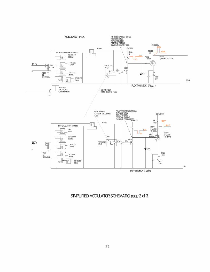
To understand the operation of the modulator, refer to Drawing 430_116, "SimplifiedModulator Schematic". The modulator is based on two high-power switch tubes. The upper switchtube, V301, turns the beam on by connecting the mod anodes to a -55kV tap on the power supply, a
voltage midway between cathode and anode potential. (This voltage is adjustable; see Section 13.3).The lower switch tube, V401 (the “tail clipper”), turns the beam off by connecting the mod anodes toa supply voltage of -115kV, 5kV lower than the power supply B- voltage. As in any totem polecircuit, it is important that both tubes must never be simultaneously turned on (“shoot through”).These tubes, Machlet type ML8038, can handle currents up to 175A and standoff voltages up to125kV. Each switch tube dissipates 2665W in filament power (13.0V @ 205A). Since the uppertube must pull the mod anodes up from -115kV o -55kV, its cathode, rather than its plate, must beconnected to the mod anodes. And since the tube's drive voltage (grid voltage) is referenced to itscathode, the chassis of its drive circuit must be tied to its cathode and hence to the mod anodes.Because this entire chassis is pulled up and down between -55kV and -115kV, it is known as the"floating deck". The two mod anodes in parallel are equivalent to a capacitor of 2 x 75pF = 150pF.

50
The modulator's job is to charge and discharge this capacitance. But the parasitic capacitance of thefloating deck itself to ground is about 900pF. The modulator does much more work charging anddischarging its own chassis, the floating deck, than the useful work it does in charging anddischarging the klystron mod anodes! The charge and discharge currents are large; to charge 1050pFto 55kV in 1 microsecond, the average current during the microsecond will be CV/10-6 = 58 Amperes.
13.1 Modulator Circuit Description (Floating deck charges mod anode up; buffer deck discharges it).
Referring to the Simplified Modulator Schematic, Dwg. 430_116, the floating deck is at the top of thepage. The cathode (filament) of the switch tube, V301, is tied (through a 9-ohm resistor) to thechassis of the floating deck and this chassis is tied to the klystron mod anodes. When the grid of theswitch tube is made positive with respect to its cathode the tube conducts and pulls the floating deckup to its plate potential, the -55kV tap from the beam supply. The positive grid drive comes from a2200V power supply on the floating deck. This grid drive voltage is applied by a cathode followercircuit made of two 4_400A tubes in parallel (V303 and V304). The presence of light in the opticalcommand fiber causes the grid voltage of V302 to fall. This tube turns off and its plate voltage risesfrom 500V to 1000V. The cathode follower delivers this plate voltage to the grid of V301, the switchtube, turning it on. A floating bias supply in series with the switch tube grid maintains the grid atabout -1000V between pulses to keep it cut off. The operation of the clamp tube, V307 is explainedlater. Note that if V302 has low emission, the deck willremain on, causing ‘shoot-through’, i.e. both decks conducting at the same time.

51
SIMPLIFIED MODULATOR SCHEMATIC: page 1 of 3
FIBER TO BUFFER DECK
120V
FIBER OPTIC TRANSMITTER BOX
BEAM ONCOMMANDFROMCONSOLE
OPTO-ISOLATOR
PWFIBER TO FLOATING DECK
5V PWR SUPPLY
1 uSECDELAY
2.5 uSECONE-SHOT 2.5 uSEC PULSE
BEGINNING 1 uSECAFTER FALL OFFLOATING DECK PULSE
MOD ANODEMONITOR BOX
MOD ANODEVOLTAGE SAMPLETO MONITORINGCIRCUITRY IN CONSOLE
120VAC +/- 15V150mA
.0471MEG
52
BUFFER DECK (-115kV)
FD+2200V
BD+2200V800mA
BD+100V50mA
BD-200V150mA
120V
120V
120V62.5 A
FD+2200V800mA
FD+100V50mA
FD-200V150mA
BUFFER DECK PWR. SUPPLIES
+FLOATING DECK PWR SUPPLIES
5kVBIAS
+
R323
V3024-400A
MOD
FIBER OPTICINPUT
T3091:1100kV ISOL.
T4091:1100kV ISOL.
FLOATING DECK ( V )CAPACITIVEPICKUP PLATEFOR MONITORING
MODULATOR TANK
FIBER OPTICINPUT
+BD+15V
FD+15V
LIGHT IN FIBER TURNS ON SWITCH TUBE
LIGHT IN FIBER TURNS ON TAIL CLIPPERTUBE
50V
BD ZENER BIAS
FD ZENER BIAS
T407
T307
FOf
FOf FOf
FOb
FOb
FOf (FIBER OPTIC ON) BRINGSTHIS POINT DOWNTO FLOATING DECKPOTENTIAL, TURNINGON V301, THE SWITCH TUBE.
50V
6k
V4024-400A
6kR423
BD+2200V
500V(PULSES TO 1000V)
R4262.5k
600V(PULSES TO 1100V)
R421250
R321250
Q401
BD+100V
FOb
FOb (FIBER OPTIC ON) BRINGSTHIS POINT DOWNTO BUFFER DECKPOTENTIAL, TURNINGON V401, THE TAIL CLIPPER
0V
50V
500V
1500V
Q301
0V
R3481k
FD+100V
500V (PULSED TO 1000V)
FD+10
500V
1500V
40V
6.8k
SIMPLIFIED MODULATOR SCHEMATIC: page 2 of 3

53
BUFFER DECK (-115kV)
BD+100V
+
C441
CR439
R44239V BIAS
CR427CR426
MODFLOATING DECK ( V )
ARC ANDRESULTINBODY CUR
2.5 OHMS
0.67 OHMS
B+ BUS
VMOD
V25KLYSTRON A
LITTONL3403
OR L5773
V26KLYSTRON B
LITTONL3403
OR L5773
BEAM SUPPLY HV BUSHING
5kV FROMFLOATINGBIAS SUPPLY
T3101:1
200V BIAS
CGP
R30910k
5 mAFROM ZENER SUPPLY
10k
.012
R441470
CLAMP TUBE PREVENTS TAIL CLIPPERTUBE FROM TURNING ON VIA TAILCLIPPER'S GRID-TO-PLATE CAPACITANCEWHEN SWITCH TUBE TURNS ON
C310
C410
5 mAFROM ZENER SUPPLY
T411 1:1200V
1400V ZENER STRING
R4262.5k
600V(PULSES TO 1100V)
V4103E29
R4509 OHMS
R421250
R321250
C GP
R3439 OHMS
GRID FAST CHARGE PATH
GRID CURRENT LIMITER
MODULATOR HV BUSHING
V401TAIL CLIPPER MACHLETTML8038(ORIG. DP11)
V301SWITCH TUBEMACHLETTML8038(ORIG. DP11)
SEE ORIGINAL MANUAL, p88, FOR EXPLANATION OF HOW REVERSE GRID CURRENT FROM V401 FIRES THEPNPN DIODE TO PRODUCE A POSITIVE DRIVE PULSE FOR THE GRID OF V410, THE CLAMP TUBE.
10k
mAMETER SHOWSZENER STACK ISCONDUCTING(APPROX 60mA @ 90kV HV) 150M
1001k
ZENER STACKPROVIDESMOD VOLTAGEADJUSTMENT
1OkV
CAPACITORBANK
+
-
+
-
CONTROLLEDBY INDUCTROL
HV SUPPLYTOP HALF
HV SUPPLYBOTTOM HALF
HV/2
HV/2
uA MODULATORVOLTMETER
B+ BUS (almost ground)
B- BUS (HV SUPPLY)
25
525k150M
RIPPLE FILTER
HV METER500uA FS"0-150kV"
B+ BUS (almost ground)
B- BUS (HV SUPPLY)
TO CROW BAR 0.16 OHMBODY CURRENTSENSOR
GROUND
12uF
0.5uF
BD+2200V
V4044-400A500V
1500V
FD+2200V
500V (PULSED TO 1000V)
V3034-400A
V3073E29
FD+100V
R3265k
500V
1500V
C3460.12
R3421250
1400V
400V
V3044-400A
2000V
1000V
0V
-1kVGRID DISCHARGE PATH220
0V
150V
0V
120V (13A)
PNPN DIODECR428
R4446.8k
R445220
V4034-400A
10uSEC
100VOV
25 (NICHROME)B- BUS (-110kV)
+
8kV SPARK GAP
1400V ZENER STACK
2.5kV SPARK GAP
2.5kV SPARK GAP
4MR416
BLEEDERPK DISSIPATION 625WAVG DISS. 37W
CLAMP TUBE PREVENTS TAIL CLIPPERFROM TURNING ON SWITCH TUBE VIASWITCH TUBE'S GRID-TO-PLATECAPACITANCE
SIMPLIFIED MODULATOR SCHEMATIC: page3 of 3
DESIGNED FOR RISE AND FALL TIMES OF 5uSEC
SIMPLIFIED MODULATOR SCHEMATIC: page3 of 3
DESIGNED FOR RISE AND FALL TIMES OF 5uSEC
SIMPLIFIED MODULATOR SCHEMATIC: page3 of 3

54
The buffer deck is at the bottom of the simplified modulator schematic. Its switch tube, V401, pullsthe mod anodes (and the floating deck) down to the potential of the buffer deck chassis (5000 voltslower than the beam supply B- voltage). This switch tube is known as the "tail clipper" because it isused only to produce a momentary pull down to discharge the capacitance of the mod anodes and thecapacitance of the floating deck chassis. This discharge leaves mod anode (and floating deck) 5000volts more negative than the klystron cathode, completely turning off the klystron beam current. Oncethe tail is clipped, the floating deck is then maintained low by the 4 Megohm hold-down resistor,R416, between the floating deck and the buffer deck. The drive circuitry for V401, the tail clipper, isalmost identical to the drive circuitry in the floating deck, comprising a cathode follower (V404 andV403 in parallel) and a voltage amplifier (V402) to increase the signal from the fiber optic receiver.The buffer deck is turned on just after the floating deck is turned off and is kept on for a fixed 2.5microseconds, which is enough to discharge the mod anodes and the floating deck. Note that if V402has low emission, the buffer deck will stay on, causing “shoot-through”, i.e. both decks conducting atthe same time.
Each deck has a 3E29 as “clamp tube” to discharge its switch tube grid. To see why this is necessary,consider first V301, the floating deck switch tube. At the end of a pulse, the switch tube has beenturned off by driving the grid negative. One microsecond later, the buffer deck tube, V401, starts its2.5 microsecond pulse, pulling the floating deck down in voltage. As the floating deck is pulleddown, the grid-to-plate voltage of V301 rises, so current must flow out of the grid. If there is not alow impedance path for this current, the grid to cathode potential will rise, trying to turn on V301 atthe same time as V401: the dreaded “shoot-through” situation. The discharge path for the grid currentis the 5k resistor, R326. Since the cathode follower is in parallel with this resistor, the combination isa low impedance path - until the grid current exceeds the bias current in the resistor. At that point, thecathode follower tubes turn off and the discharge path is the high impedance 5k resistor. It isnecessary to provide a low impedance path that will stay active during the entire discharge. Theclamp tube, V307, does this job. This tube is turned on automatically as current in the tail clippertube, V401, flows through the primary of the transformer T310. The secondary winding applies apositive pulse to the grid of the clamp tube, activating the clamp turned on while the floating deckdischarges.
The buffer deck clamp is similar. The pull-up of the floating deck tries to lift the grid voltage ofV401, which would turn on V401 together with V301 (shoot-through). The scheme used to turn onthe buffer deck clamp is more circuitous than the simple transformer used to turn on the floating deckclamp. As the floating deck begins to rise in potential, grid current wants to flow out of the grid of

55
V401, through to the plate-to-grid capacitance of that tube. This initial current flows through theprimary of a one-to-one isolation transformer, T411. The voltage induced in the secondary triggers aone-shot, which supplies a 200volt, 20usec pulse to turn on the clamp tube. The clamp tube cathodeis biased at +100V, so its grid bias rises to 100V and is held there by the grid-cathode diode action onthe positive grid current (which is limited by R445). Note that the buffer deck clamp tube is notactivated by the normal turn-on of the buffer deck because the charging current for the grid of V401flows backward through the Zener diode CR426 which, acting as an ordinary diode, shorts theprimary of T411. (Even without this diode action, the pulse produced at the transformer secondarywould have the wrong polarity to trigger the one-shot. And, in any event, CR427 snubs the negativepulse).
13.2 Modulator ControlBoth the floating deck and the buffer deck are controlled with optical fibers. These fibers provideisolation from chassis that are as much as 120 kV away from ground potential. The floating deckfiber is turned on and kept on during the time the klystron beam is to be on. The buffer deck fiber isturned on 1 usec after the floating deck fiber is turned off and is then turned off after a fixed 2microsecond delay. Two microseconds is sufficient time for the buffer deck to discharge thecombined capacitance of the mod anodes and the floating deck We are presently installing anadditional fiber to each deck. These fibers will activate the clamp tubes by external command, whichwill make it easier to test and trouble-shoot the decks individually. But the clamp tube turn-oncircuits described above will be retained, “ORed” with the external commands, as backup protection.
13.3 Modulator Supply VoltageThe figure below shows how the modulator supply voltage is derived from the half-voltage point ofthe beam supply. This tap on the beam supply has ripple, which is filtered by R86 and C36.Adjustability is provided through a stact of 50 Zener diodes, each of 50 volts. The voltages indicatedin the figure correspond tothe operating condition for the never L5773 klystons: 95kV beam supply, 48.5kV mod anodeamplitude.
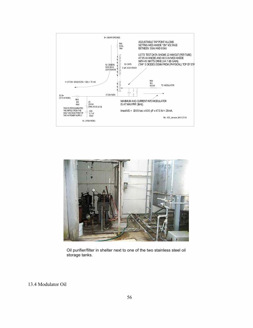
56
R46525k, 7kW
0.1uF, 600V EACH50 ZENERS50M 200Z(200V EACH)
50 CAPS
B+ (NEAR GROUND)
R84100 400W
R8610K4kW
25200W(R48,49,50,& 51)
C360.7 uF55kV
THIS FILTER ELIMINATES THE RIPPLE FROM THE HALF VOLTAGE POINT OFTHE HV POWER SUPPLY.
B- (-95kV NOM.)
I= (47.5kV -10kV)/(525k + 10k) = 70 mA
1/2 B+(47.5 kV NOM.)
47.5kV NOM.
TO MODULATOR
MAXIMUM AVG CURRENT INTO MODULATORIS AT MAX PRF (1kHz).
ImaxAVG = 1000/sec x 600 pF x 47.5 kV = 28mA.
ADJUSTABLE TAP POINT ALLOWSSETTING MOD ANODE "ON" VOLTAGE BETWEEN 55kV AND 65kV.
L5773 TEST DATA SHOWS 1.3 MW OUT (PER TUBE)AT 95 kV ANODE AND 48.5 kV MOD ANODEWITH 45 WATTS DRIVE (44.7 dB GAIN).(TAP 5 DIODES DOWN FROM (PHYSICAL) TOP OF STA
file: 430_zen.ecw jbh 9-17-04
Oil purifier/filter in shelter next to one of the two stainless steel oilstorage tanks.
13.4 Modulator Oil

57
A 2000 gallon tank of mineral oil (Texaco transformer oil, codigo 1515) provides high voltageinsulation and convection cooling for the modulator. The buffer deck and floating deck are bothsubmerged in this oil. Two 2500 gallon stainless steel tanks provide temporary storage space for theoil, which is pumped out of the modulator tank when the modulator circuitry is repaired or modified.The oil filtering and storage system is shown in the figures on the following pages.
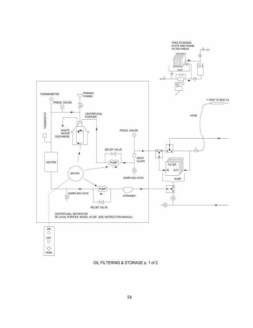
58
FILTER
IN OUT
SUMP
SAMPLING COCK
HOSE
STRAINER
PRIMINGFUNNEL
SAMPLING COCK
CENTRIFUGALPURIFIER
HEATER
PRESS. GAUGE
THERMOMETER
ON
TEMP.
OFF
CENTRIFUGAL SEPARATORDE LAVAL PURIFIER, MODEL 45-36F (SEE INSTRUCTION MANUAL)
SIGHTGLASS
RELIEF VALVE
PUMP
MOTOR
PRESS. GAUGE
RELIEF VALVE
1" PIPE TO MOD TA
THER
MO
STAT
WASTEWATER
DISCHARGE
SUMP
OUT
ONOFF
IN
FREE-STANDINGPLATE AND FRAMEFILTER PRESS
PUMP
OIL FILTERING & STORAGE p. 1 of 2
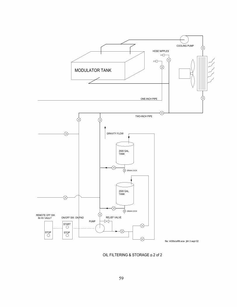
59
2500 GAL.TANK
2500 GAL.TANK
DRAIN COCK
DRAIN COCK
PUMPRELIEF VALVE
GRAVITY FLOW
MODULATOR TANK
COOLING PUMP
TWO-INCH PIPE
HOSE NIPPLES
ONE-INCH PIPE
file: \430tx\oilfilt.ecw jbh 3 sept 02
REMOTE OFF SW. IN HV VAULT ON/OFF SW. ON PAD
STOP STOP
START
OIL FILTERING & STORAGE p.2 of 2

60
14. Cooling System (see section 3.3)15. Monitoring SystemRefer to the monitor system schematic, Dwg. No. 430_107, which replaces the original drawing,J349C107. The ac and dc power metering is straight forward. The meters themselves are on the frontpanels in the control console or inside the console, behind the door on the right-hand side. Most ofthe metering circuitry is obvious. Less obvious metering is discussed below.
15.1 AC line voltage monitorThree digital voltmeters are connected to the three phases of the transmitter’s input power line,following a transformer step-down from 4160 volts. The transformer secondary has a wyeconnection, so each meter measures the voltage from one leg of the wye to the grounded centerconnection. The nominal reading for each phase is 120 V. A selector switch allows the meters to read“Commercial” or “Generator”: the former means the meters are connected as described above to theinput power line of the transmitter. The latter, “Generator”, means that the meters are connected tothe normal house power rather than the lines dedicated to the transmitter. When commercial powerfails, the observatory generator does not supply power to the transmitter power lines, but does supplyhouse power, hence “generator”. This metering feature, not needed for transmitter operation, wassuppled simply because there was not another set of meters in the control room to read the linevoltage during emergency generator operation.
15.2 Klystron solenoid magnet currentsEach klystron has eight solenoid magnets to prevent divergence of the beam. A meter is provided forevery magnet (16 meters). The original meters were meter relays with an adjustable auxiliary contactthat would close if the current falls below the selected value. The opening of any one or more of the16 contacts would operate a relay to open the interlock chain. The original meters, no longeravailable, are being replaced with ordinary meters, fitted with circuitry to provide the auxiliarycontact feature.This circuitry is on the last page of the metering system schematic, Dwg. No. 430_107. A small pushbutton below each meter lets the operator view the set point, which can be adjusted by a trim pot,accessible through a hole next to the push button. A red magic marker can be used on the glass toindicate the position of the set point. The meter circuitry includes a pulse stretcher; if there is amomentary interruption of the current (e.g. from a loose contact or connector), the meter will drop toa low value for about 1 second - long enough to be noticed by a sharp-eyed troubleshooter. (NOTE:AS OF 6-05, THESE ‘METER RELAY’ CIRCUITS HAVE STILL NOT BEEN INSTALLED).

61
15.3 Klystron filament power metersEach klystron has a dynamic watt meter to monitor its filament power. These readings should thus betrue power indicators, independent of the ac waveform.
15.4 Forward and reverse RF power meteringThe transmitter is fitted with many directional couplers. Most are in waveguide. At least one is incoax, in the line between the IPA and the PA. Most of these directional couplers are fitted with diodedetectors, and supply their respective meters or threshold detector circuits with dc voltages thatrepresent average power. However six couplers bring their RF samples via coax cables to bulkheadconnectors on the front of the console, where they can be connected to the built-in HP power meter orexamined directly with a high speed oscilloscope. These six are total output power, waster loadpower, and forward and reverse powers at the outputs of each klystron. All six are derived fromnominal 50 dB directional couplers. But to the 50 dB must be added the cable attenuation and thevalue of any attenuators inserted in the lines. The lines, RG9 coax, will contribute about 4 dB of loss (4.6 dB/100ft).
Total forward power port: This port contains a 15 dB attenuator, AT709. Thus its total couplingfactor is around -69 dB, i.e. 50dB + 4dB + 15dB. 150kW would produce 10 log 150 + 60 -50 -15 -4dBm = 12.8 dBm (19 mW).
Total reflected power port: This port circuit contains a 5 dB attenuator, AT708, so 15kW wouldproduce a reading 12.8 dBm (19 mW).
Klystron A and Klystron B forward power ports: These ports contain 12 dB attenuators, AT704and AT706, so 75 kW would produce 12.8 dBm (19mW).
Klystron A and Klystron B reflected power ports: These ports contain 2 dB attenuators, so 7.5 kWwould produce 12.8 dBm (19 mW).
Obviously the designers arranged things so that when the HP power meter head is moved from onesample port to another, the expected readings will be about the same. The calibration of all theseports should be verified and recorded.
All the other directional couplers are connected directly to diode detectors. These ports shouldlikewise be tested. It would be good to test first the diode detector/meter circuitry alone.

62
List of meters:Meter Function Type Location Schem. ref. M2 AC line voltage 0-150VACM3 Kly A filament watts 0-1500W/relay console 107,106M4 Kly B filament watts 0-1500W/relay console 107,106M5 Kly A filament running timeM6 Kly B filament running timeM7 Rectifier filamentM8 Rectifier filamentM9 Rectifier filamentM10 beam current 0-10A/relay console 107,106M11 body current 0-500mA/relay console 107,106M12 kly A coll. current 0-5A/relay console 107,106M13 kly B coll. current 0-5A/relay console 107,106M14 beam voltage 0-150kV/relay console 107,106M15 Kly B vac-ion pressureM16 Kly B vac-ion pressureM17 cap. bank short detect. 50ma w/relay Cap. bank 430_106, 430_107M18 4160 VAC phase detect 0-150VAC/relay 430_106,430_107M19 4160 VAC phase detect 0-150VAC 430_106,430_107M20 208 VAC phase detect 0-150VAC 430_106,430_107M21 208 VAC phase detect 0-150VAC 430_106,430_107M22 mod. supply voltmeter Console 430_107, 430_107
M101-24 IPA beam currentM102-24 IPA body currentM103-24 IPA collector voltsM104-24 IPA beam voltage
M201-24 IPA Pre-focus magnet current ConsoleM202-24 IPA 1st body magnet current ConsoleM203-24 IPA 2nd body magnet current ConsoleM204-24 IPA 3rd collector magnet current Console

63
M601 kly A, magnet #1 0-10A/relay Console 107M602 kly A, magnet #2 0-10A/relay Console 107M603 kly A, magnet #1 0-10A/relay Console 107M604 kly A, magnet #1 0-10A/relay Console 107M605 kly A, magnet #1 0-10A/relay Console 107M606 kly A, magnet #1 0-10A/relay Console 107M607 kly A, magnet #1 0-10A/relay Console 107M608 kly A, magnet #1 0-10A/relay Console 107M609 kly B, magnet #1 0-10A/relay Console 107M610 kly B, magnet #2 0-10A/relay Console 107M611 kly B, magnet #3 0-10A/relay Console 107M612 kly B, magnet #4 0-10A/relay Console 107M613 kly B, magnet #5 0-10A/relay Console 107M614 kly B, magnet #6 0-10A/relay Console 107M615 kly B, magnet #7 0-10A/relay Console 107M616 kly B, magnet #8 0-10A/relay Console 107
M701 dummy load powerM702 waster load powerM703 Kly A&B Output powerM704 Kly A&B Input powerM705 IPA input powerM706 IPA Output power Console 107M707 HP power meter Console
16. AC Power Control Circuitry
A detailed description of the power and control circuitry begins on page 10 of the original manual.Refer to Drawing 430_106, “AC power distribution overall”. The transmitter is almost entirelypowered by the 4160 volt 3-phase service that enters the main disconnect switch in the transmitterroom on the wall of the high voltage vault (see figure below). This switch is normally on; it is turnedoff only for maintenance work.
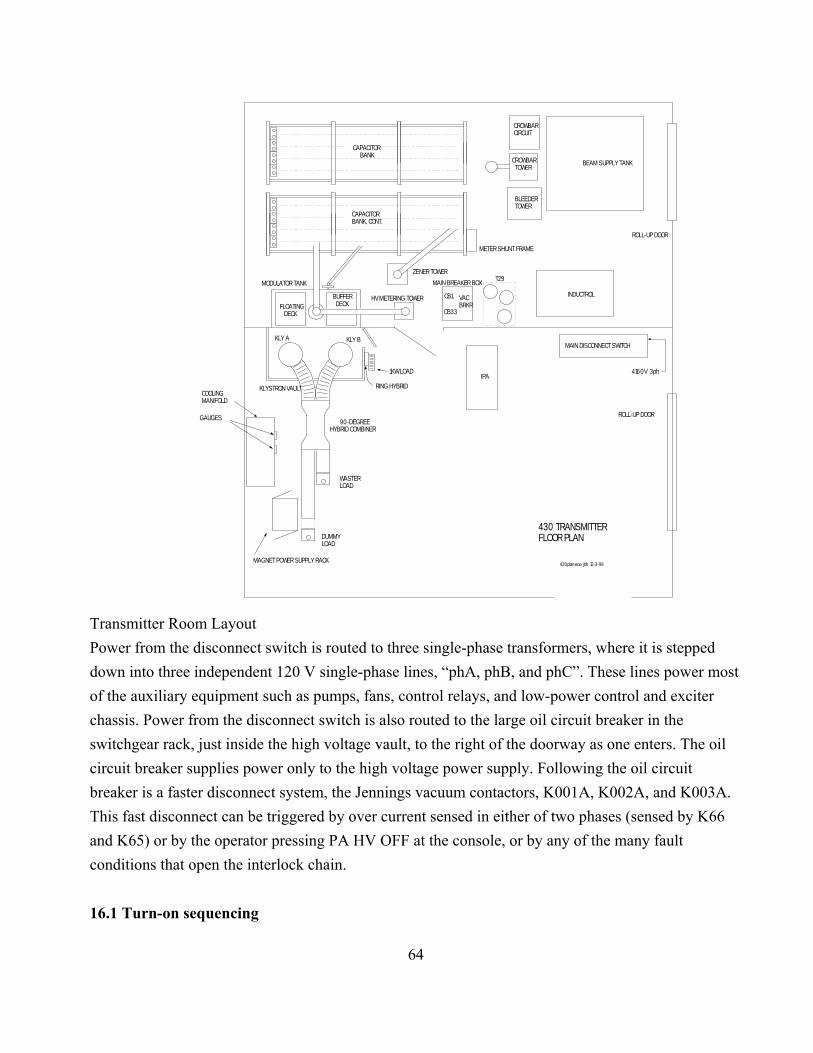
64
BEAM SUPPLY TANK
INDUCTROL
WASTERLOAD
DUMMYLOAD
KLY BKLY A
FLOATING DECK
CROWBARCIRCUIT
BLEEDERTOWER
KLYSTRON VAULT
IPA
MODULATOR TANK
ZENER TOWER
METER SHUNT FRAME
COOLING MANIFOLD
RING HYBRID
1KW LOAD
HV METERING TOWER
GAUGES
CROWBAR TOWER
90-DEGREEHYBRID COMBINER
CAPACITOR BANK
CAPACITOR BANK, CONT.
BUFFER DECK
T29
CB1
CB33
VACBRKR
MAIN BREAKER BOX
MAGNET POWER SUPPLY RACK
ROLL-UP DOOR
ROLL-UP DOOR
4160V 3ph
430 TRANSMITTERFLOOR PLAN
430plan.ecw jbh 12-3-98
MAIN DISCONNECT SWITCH
Transmitter Room LayoutPower from the disconnect switch is routed to three single-phase transformers, where it is steppeddown into three independent 120 V single-phase lines, “phA, phB, and phC”. These lines power mostof the auxiliary equipment such as pumps, fans, control relays, and low-power control and exciterchassis. Power from the disconnect switch is also routed to the large oil circuit breaker in theswitchgear rack, just inside the high voltage vault, to the right of the doorway as one enters. The oilcircuit breaker supplies power only to the high voltage power supply. Following the oil circuitbreaker is a faster disconnect system, the Jennings vacuum contactors, K001A, K002A, and K003A.This fast disconnect can be triggered by over current sensed in either of two phases (sensed by K66and K65) or by the operator pressing PA HV OFF at the console, or by any of the many faultconditions that open the interlock chain.
16.1 Turn-on sequencing

65
A series of time delay relays and electro mechanical timers energize the transmitter circuits asfollows:
Operator pushes the button PA System On . Relay K4 closes and one of its contact pairs turns on K6and K8, which turn on the heat exchanger fans. The other contact pair on K4 shorts the push button,latching K4, which turns on the green lamp and applies power to K9, a 5-second time delay relay.
5 seconds later, K9 applies power to K7 and K13, which turn on the main pump and thebooster pump and energizes K10, a 2-second time delay relay.
2 seconds later, K10 turns on K14, which once turned on the HV rectifier filaments, and K11,a 7-second time delay relay.
7 seconds later, K11 turns on K15, which energizes the magnets and energizes K12, a 2-second time delay relay.
2 seconds later, K12 turns on K20, which supplies power to the klystron filaments andenergizes K24 and K25 which are 15 minute timers, to allow the filaments to warm up.
15 minutes later, the contacts of K24 and K25 to complete the interlock chain, turning on theorange lamp PA HV READY.
The operator can now push the button PA HV On. This will turn on and latch the red lamp PA HV Onand close and latch the vacuum contactors in the 4160V 3-phase lines to the Inductrol. Assuming theIPA has been turned on, the operator can now raise the IPA’s high voltage and then the PA’s highvoltage.
16.2 Power Tripping and Resetting About one hundred different conditions break the interlock chain (see dwg 430_106, p5) andthereby trip the PA HV ON circuit (see dwg 430_106, p2). Once the fault has been corrected,restoring continuity to the interlock chain, the operator can again turn on the high voltage. (Somefault situations require the operator to first press the RESET button).

66
17. Timing system 430 TX Timing Generator (mounted in the transmitter console) 17.1.0 IntroductionThis console-mounted unit (Figure 1) imposes protective limits or extensions, when needed, on thefour external timing request signals, converting them into four equivalent timing command signals forthe 430 MHz radar system. These limits or extensions are applied a. when the externally suppliedrequests violate specified limits and b. in the event of ac power dips. In addition to this protectivecircuitry, the unit includes an internal timing generator for stand-alone transmitter testing.
17.2.0 Control Signal RequestsFour externally supplied TTL lines are used to control the radar timing. These lines (including theirtraditional names) are listed below in the usual order of activation.
1.Receiver Protection Request (IPP)This pulse turns on the receiver protectors (monoplexers). Normally the computer raises thisline about 5 microseconds prior to starting the RF pulse, to be sure that the receiver is fullyprotected before any RF (leakage) arrives. Protection Request should be maintained highthroughout the RF pulse and lowered a few microseconds after the pulse to avoid hitting thereceiver with echoes from close-in clutter and transmission line reflections. (If only a briefrequest is sent, followed in less than 25 microseconds by an RF Request, (as with theprevious timing system) the unit will produce a protection command that stays high until 20microseconds after the RF Request goes down).2. Beam Request (Pulse) The klystrons can produce power only when their beams are on. It is good practice to keepthe beams off until the receiver protection is active, as the klystrons can emit a burst of noisewhen the beam turns on, even while the RF drive is still absent. When only the beams are on,the klystrons produce enough noise power to render the receiver useless and, in the event of acrowbar, the klystrons may produce a potentially damaging noise pulse). Thus Beam Requestshould be raised no sooner than 2 usec after Protection Request is raised and lowered beforeProtection Request is lowered.3. RF Request (RF Gate)This pulse applies RF drive to the klystrons. The RF Request should not be raised until thebeam current is fully on, as specified by the klystron manufacturer. Note that RF Request canalso be turned off and back on during the beam pulse, in order to transmit a burst of two ormore shortpulses.4. Phase Request (Phase)This signal flips the phase of the transmitted signal by180degrees and is used to apply phasecoding to the transmitted signal.

67
430 MHz TRANSMITTER TIMING GENERATOR
FIGURE 1. FRONT AND REAR PANEL LAYOUTS
430 MHz TRANSMITTER TIMING GENERATOR
OR-3V
ORFIBER
PROTECTION ACK. IN
EITHERTTL
COMMAND
FRONT AND REAR PANELS
ACK. MONITORTO SCOPE
TTLDIFFERENTIAL
INPUT REQUESTS MONITORTO CONSOLESCOPE
OUTPUT COMMANDS TO TX.
BEAM TTL TTL
TTL
j7
j8
j9
j10
j12 TTLj23 j26 j27 j28
j29
j30
j313-PH. VOLT.SENSE
1 AMP SLOWBLO
ACK.
MONITOR PORTS
BEAM
RF
PHASE
PROTECT
REQUEST
j3
j4
j5
j6
LOCAL
REMOTE RF REQ W/O ACK.
POWER LINE DIP
LAMPRESET
ERROR SYNC.
j32
PROTECT -3Vj11 TTLj22TTL
TTL
FIBERj19j15
j16
j17
PHASE j14 TTLj25TTLj18
RF j13 TTLj24TTL
j21j20
j19a
GREEN LAMPS(LOGIC PROBE INDICATORS: ON FOR STEADY "1" OFF FOR STEADY "0" BLINK WHEN PULSES ARE PRESENT)
RED LAMPS LATCHERRORS. PUSH BUTTON RESETSLAMPS AND ALSO SERVES AS LAMP TEST
TOGGLE SWITCH IS NORMALLYDOWN TO PREVENT ACCIDENTALLYTURNING KNOB PAST 6% TO CW.WITH THE SWITCH DOWN, TURNINGTHE KNOB TO CW LEAVES DUTYCYCLE AT 6%.
ERROR LAMPS
430 MHz TRANSMITTER TIMING GENERATOR
32 mS16 mS8 mS
4 mS
2 mS
1 mS 512 mS
256 mS
128 mS
64 mS
0
.1%
.2%
.5%
1% 2%
3%
4%
5%
6%
LOCAL IPP LOCAL DUTY CYCLE
100%(CW)
ENABLE CW
DISABLE CW
RCVR INTERLOCK( Y-SWITCH INTERLOCK)TTL LO OR SHORTENABLES RF & MONOPLEXERS
RCVR. INTERLOCK (Y SWITCH)j1
LOCAL PHASE INPUT (TTL)
AC ON
"ERROR SYNC" LATCHED HI WHENANY ERROR LAMP LIGHTS. USED TOTRIGGER LOGIC ANALYZER OR SCOPE.
PULSE TRUNCATED
PULSE SUPPRESSED
BEAM DUTY OVER 6%
PRF OVER 1 kHZ
ACK. FAILURE
timegen1a.ecw8-19-04
17.3.0 ControlSignal CommandsThe request signals are converted into the command signals as follows:
1. Receiver Protection Command (sent to the platform-located monoplexers) The protection command is high if and only if any of the following are true:
a. Protection Request is high (the intended, i.e. nominal form of protection)b. Beam or RF is high (automatic protection)c. Protection Request has been raised in the last 80 microseconds: one can simply pulsethe protection request and then rely on automatic protection. (This provides compatibility with the request format used with the former timing control system).d. Beam or RF has been lowered in the last 5 microseconds (extended automaticprotection)e. Line voltage fault (an ac power dip is occurring)
2. Beam Command (sent to the klystron beam modulator)The Beam Request is first sent through the PRF Limiter, a block which will ensure theaverage PRF will not exceed 1.04 kHz. (No more than 16 pulses are allowed between the

68
ticks of an internal 15.36 msec clock). The PRF-limited Beam Request is next sent throughthe Duty Factor Limiter, a block that ensures the beam duty factor will not exceed 6.25% (the beam will be truncated if it has been on for a total of 2.099 msec in any interval of length33.6 msec). The output of this block is the Granted Beam Request Normally, requests arelegal and the Granted Beam Request is identical to the Beam Request. Finally, the GrantedBeam Request, is OR’d with LOCAL.AND.CW, to form the Beam Command. Thetransmitter had a seldom used CW mode; setting this unit to “LOCAL” and its Duty Factorselector switch “CW” causes the receiver protection, rf, and beam commands all to be high.(An “CW Enable” toggle switch prevents accidental selection of “CW”).
Note: A copy of the Beam Command is also sent to the Low-Level Modulator Chassis“unblank” (i.e. enable) the exciter. (The RF Command provides fast turn on and turn off, but,additional blanking is necessary to provide total suppression of feed-through during receiveperiods).
3. RF Command (sent to the low level RF drive circuits in the Freq. Synthesizer / Low-levelAmp chassis and in the Low-Level Modulator chassis).The RF command is the AND of the RF Request, the Protection Acknowledge signal, and a 2usec delayed version of the Beam Command. This prevents driving the klystrons until thebeam is fully on and, of course, prevents driving the klystrons when the receiver protection isnot active. The RF Command is also forced low if a power dip is occurring.
4. Phase CommandThe Phase Request is simply passed along to the Low-level Modulator chassis. The PhaseCommand LED on the front panel blinks when the Phase Cmd Request is toggling.

69
CMDIN
CMDIN
CMDOUTACKOUT
ACKIN
ACKOUT
CONSOLE MOUNTED TIMING GENERATOR
MASTERMONOPLEXER( DOME)
SLAVEMONOPLEXER(CAR. HOUSE)
UPS UPS
PROTECTION REQUEST
RF REQUEST RF CMD
TO LOW-LEVELMODULATION CHASSIS
RCVR PROTECTIONCMD TO PLATFORM
REQUESTED RCVR PROTECTION
CW
OS
LOCAL. AND.CW
MINIMUM RCVR PROTECTION REQUEST RCVR PROT. CMD.
REMOTE
LOCAL
5 MHZCLK
see fig. 6
REMOTE
LOCAL
2 usec
INTERNAL PULSEGENERATOR
BEAM REQUEST
PHASE REQUEST
BEAM COMMAND TO MODULATOR
5 MHZ CLK5MHZ OSC.
LINE VOLTAGE FAULTREMOTE
LOCAL
REMOTE
LOCAL
5V PWRSUPPLY
"PHASE FLIP INPUT(TTL)"
PULSESTRETCHER
see fig. 7
GRANTED BEAM REQUEST
LOCAL. AND.CW
see fig. 3 see fig. 5
T1= 900usecT2= 2usec
PRFLIMITER
IN OUT INOUT
BEAM CMD.
UNBLANKING COMMAND TO LOW-LEVEL RF MODULATION CHASSIS
110 VAC
UPS
LOW VOLTAGE ONONE OR MORE PHASES
threshold
110 VAC
NOTE: SYMBOL DESIGNATES"LOGIC PROBE" INDICATOR:LO, HI, BLINK ON PULSE
PHASE COMMAND TO LOW-LEVELMODULATION CHASSIS
UNBLANKING COMMAND TO LOW-LEVEL AMPLIFIER CHASSIS
LINE VOLTAGE FAULT
PROTECTION ACK.FROM PLATFORM
RF REQ. W/O ACKDETECTOR
ACK
ACK FAILURE DETECTOR(ACK GOES LOW WHILERF REQ IS HIGH)
5 MHZ CLK
TRUNCATE ON ACK. ERROR
RF REQUEST
430 MHZ TRANSMITTER TIMING GENERATOR
FIGURE 2. BLOCK DIAGRAM
HEAVY LINES INDICATE NORMAL SIGNAL FLOW
PULL UP
VCCCONTACT IN K333(Y-SWITCH SENSE RELAY)
RECEIVER (Y-SWITCH) INTERLOCK
TTL HI (OR OPEN) SUPPRESSESRF AND DISABLES RECEIVERPROTECTION (MONOPLEXERS)
TTL LO (OR GND) ENABLES RFAND ENABLES RECEIVER PROTECTION(MONOPLEXERS)
AC ONFUSE
80 usecLINE VOLTAGE FAULT
OS5usec
AUTOMATICPROTECTIONWRT BEAM
EXTENDEDAUTOMATICPROTECTION WRT RF
AUTOMATICPROTECTIONWRT RF
DELAYED ENABLEIMMEDIATE DISABLE
DUTY FACTOR ANDPULSE LENGTH LIMITER
timgen1a.ecw jbh 8-20-04
17.4.0 Overall Circuit DescriptionThe transmitter commands described above are generated by the logic shown in Figure 2, a blockdiagram. In this figure, the normal signal paths are shown in bold. The individual blocks are describedbe low.

70
BEAMREQUESTOUT
430 MHz TRANSMITTER TIMING GENERATOR
FIGURE 3. PRF LIMITER - SIMPLIFIED SCHEMATIC DIAGRAM
Q5
CLEAR5-BIT RIPPLE COUNTER
CLK
BEAM REQUEST IN
QCLK
CLR
15.36mSEC
timegen1a.ecw8-19-04
17.4.1 PRF Limiter Figure 3 is a simplified schematic diagram of the PRF Limiter. The 5-bit ripple counter incrementson the falling edge of the Beam Request. After 16 counts, Q5 goes high and the flip-flop is reset,turning off the output AND gate. Subsequent Beam Request are therefore suppressed until the nextreset pulse arrives to set the counter back to zero. As long as there are never more than 15 pulsesbetween resets, the Beam Request Out will be identical to the Beam Request In. Any time the PRFlimiter activates, a red fault indcator LED is lit and latched.
17.4.2 Beam Duty Factor LimiterFigure 4, a simplified schematic diagram of this block, shows the duty factor and pulse width limiter.The circuit has one principle input, BEAM REQUEST, and one output, GRANTED BEAMREQUEST. Note that the heart this circuit is the flip-flop FF1 and the AND gate U1 at the upper rightcorner. When FF1 is high, the beam request is granted (gated). In normal operation, FF1 remainshigh. The Up/Down counter counts down between pulses, usually all the way to zero, where it stops. It counts up at a 5MHz rate during pulses. If the count reaches 10496, FF1 will be reset, turning offthe GRANTED BEAM REQUEST. While the GRANTED BEAM REQUEST remains low, thecounter counts down at a rate of 1/15 x 5MHZ. The next BEAM REQUEST will turn FF1 back on. Ifthe counter has reached zero, the new pulse can be as long as 2.099 msec (producing a count of10496). If the counter has not reached zero, the new pulse must be shorter, or it will be truncated. Thus the average duty factor is forced not to exceed 1/(1+15), i.e. 6.25%.

71
QD
CLK
R
BEAM REQUEST
UP/DOWN
DIVIDE BY 15(CYCLES 1 THROUH 15)
BEAM REQUEST INTEGRATOR
5 MHz CLOCK
ZERO
CLK
UP/DOWN
CLK UP/DOWN COUNTER
ENABLEUP
U1
FF1
PRESET TO 1
ZERO
10496TRUNCATE
GRANTED BEAM REQUEST
MAX . AND. NOT ZERO
MAX(15) MAX
timegen1a.ecw8-19-04
HI
FIGURE 4. BEAM DUTY FACTOR LIMITER
BLOCK DIAGRAM
Thismodule has a secondary input, which, if pulsed, will truncate a pulse by directly resetting FF1. Thisinput is fed from the ACK Failure Detector, which provides a pulse if ACK goes down while RFRequest is high, e.g. when there is a fault in the cable taking the Protection Cmd signal to the platformor in the cable bringing the ACK down from the platform.
17.4.3 Internal Pulse Generator This unit produces local versions of the four control pulses, and is used for stand-alone testing

72
PRFSELECTORSWITCH
1 / 512 MHZ
1 / 256 MHZ
1 MHZ
CTR CLK
CTR CLK
DIVIDE BY 5
CLK
PRF COUNTER
FREE-RUNNING BINARY COUNTERWITH OUTPUTS AT 1 MHz, 1/2 MHz,1/4 MHz.... 1/512 MHz
1 MHz CLKTO SHIFT REG.
START
ON
Q
MIN (COUNT = 0)
PULSE
PULSE LENGTH COUNTER
CTR CLK
STOP
CLK
D
20 301 2 5 10 40 50 60
COUNT =
CLK
3-DECADE COUNTER WITH OUTPUTS FOR COUNT =1, COUNT =2 , COUNT = 5, COUNT =10, COUNT =20COUNT =30, COUNT=40, COUNT =50, COUNT =60
0%
0.1%0.2%
0.5%
1%
2%
3%
4%
5%
6%
5MHZCLK
100% (CW)HI
LOCAL PHASEREQUEST
DUTY CYCLESELECTORSWITCH
HI
LO
"CW"
CW
FRONT PANEL BNC JACK
FIGURE 5. INTERNAL PULSE GENERATOR
BLOCK DIAGRAM file: timgen1a.ecw
QD QD
LOCAL RCVR PROT. REQUEST
1MHz CLK
1MHz CLK1MHz
CLK
IN24-BITSHIFTREGISTER(24 us DELAY)
LOCAL RF REQUEST
PULSEDELAYED BY24 uSEC
LOCAL BEAM REQUEST
CW
Q22 Q23 Q24
LOCAL PROT. REQ.
2uS
LOCAL BEAM REQ.
LOCAL RF REQ.
23uS
21uS
ofthetransmitter. Refer to Figure 5, a block diagram of the Internal Pulse Generator.
This generator is based on two counters: the PRF counter and the Pulse Length Counter. Both countersare free running; they cycle continuously. The PRF counter, a straight binary counter, is clocked at1MHz. Its successively divided outputs are the inputs to a 10-position PRF Selector switch. Theselected output rate clocks the Pulse Length Counter, which is a 3-decade counter that cyclescontinuously from 000 to 999. The same clock is used to clock a D-type flip flop, whose output is thegenerated pulse. The flip flop is turned on when the counter state is 000 and is turned off when thecounter state is 001, 002, ......... 060, which correspond to duty cycles from .001 to .060 (0.1% to 6%).Note that a 0% duty factor (beam off) is also provided. When the duty factor selector is set to 0%, theD input of the flip flop is held continuously low. The output of the flip-flop is delayed by 24 usec by means of a 24-bit shift register clocked at 1 MHz.The shift register input and output signals are combined in some simple logic to produce the LOCAL

73
RF REQUEST pulse (which has the selected duty factor), the LOCAL PROTECTION REQUESTpulse, which begins 23 usec earlier, and the LOCAL BEAM REQUEST pulse, which begins 2 usecearler. The beam and rf requests fall at the same time. The protection request falls 2 usec later. TheLOCAL PHASE REQUEST is derived from a front panel BNC jack. For most testing, nothing will beplugged into this jack (no phase modulation).
17.4.4 Power Line Dip ProtectorThis circuitry produces a “line voltage fault” signal (1-bit) as soon as any one of the three power linephases falls below a threshold of 85 Vrms. The fault simultaneously blanks the transmitter(suppressing the RF Command), turns off the beam command, and applies receiver protection(turning on the monoplexers). Any sensed brownout is stretched an additional 1.5 seconds, so even thebriefest power dip will produce a 1.5 second blanking. Whenever this blanking occurs, a red indicatorlamp is lit and latched.
17.4.5 Antenna InterlockA rear panel BNC inputs accepts a TTL signal, which, when LOW, inhibits the transmitter (turningoff the RF pulses) and disables the receiver protection. This is used for radio astronomy observationswhere the transmitter must be inhibited to prevent receiver damage and the receiver protection must beremoved so that the monoplexer doesn’t periodically interrupt the received signal. This signal isprovided from the 430 MHz Mode/Protection panel in the receiver racks.
17.4.6 Ack(nowledge) Failure DetectorCircuitry is provided to detect any instance of the Ack line falling low while the RF Request is high.This would be the case if there is a break or intermittent connection in the cables carrying theProtection Request to the platform or the cables bringing the Acknowledge signal back down from theplatform. In the event of such an Ack Error, the pulse is truncated and a red indicator lamp is lit andlatched. The monoplexers have built-in pulse stretchers, so, if the problem is in the cabling, thereceiver will remain protected for about 20 microseconds after the Ack Error has truncated thetransmitter pulse. (Protection is need for an extended interval while the failure indication propagates tothe timing generator, the RF cut-off reaches the platform, and even longer, until reflections subside inthe long waveguide run).
A similar circuit detects any instance of RF Request going high when Protection Request is low.Such a failure would indicate faulty request timing, and lights a latched error lamp. The design of theunit (see Figure 2) ensures that protection will automatically be added before the RF request is passedto the transmitter as a command.
17.4.7 UPS for the Timing GeneratorThis unit is installed with its own UPS, just as each of the two upstairs monoplexer drivers has its ownUPS.
18. Receiver ProtectionWe can count on no more than about 25 dB of isolation from the turnstile junction. Therefore the pulse

74
power leaving the turnstile’s receiver port is about 2.5 MW - 25 dB = 7900 W. The job of themonoplexer is cut this feed through down to, say, 1 mW to prevent burning out, or severelyoverloading, the receiver. This implies a monoplexer attenuation of better than 69 dB.
18.1 430 Monoplexer - Theory of Operation
λ/4 stub for diode dc return
The monoplexer is shown above in simplified form. This device is put at the input to the receiver.When the diodes are forward biased, their resulting low impedance (about 1/10 ohm) shorts the innerand outer conductors of the coaxial feed line. This short reflects the leakage power from the turnstile(about 1 kW) to protect the receiver from burnout.
There are two diode "stations" along a 50-ohm line, separated by a distance D. Each station has 4diodes to provide a better short. If a single diode station provided, say, 50 dB of isolation, then addinga second station a quarter wave from the first would increase the isolation to 2x50 + 6 = 116 dB. Aquarter-wave separation provides the maximum isolation.
For receiving, the diodes are reverse biased. Their low resistance disappears but they still present acapacitance of about 2.1pF. Four diodes in parallel increase this to 8.4 pF which, at 430 MHzis a reactance of 44 ohms. This reactance, shunted across the 50-ohm produces a reflection coefficientshown as point A in the Smith Chart. Moving along the transmission line from point A, we arrive atpoint B (the mirror image of point A about the x-axis) where an identical station will bring us back to

75
the centerof the chart, i.e. eliminate the reflection. If the capacitance had been very small, point A would havebeen very near the y-axis. The separation on the chart would have been 180 degrees and the physicalseparation would have been 90 degrees - the separation that gives the best isolation when the diodesare in the transmit state. No compromise is made; the separation is determined by the angle between Aand B so that there will be no mismatch on receive. For our 8-diode monoplexer, the separation is only31 degrees.
We can analyze the circuit to determine the isolation as a function of the diode ON resistanceand the distance between the diode stations. The equivalent circuit is shown below at the left.A simplified version is shown at the right.
The source is made to be 2 Volts so that the output voltage, Vo, will be 1 Volt when the resistors R areinfinite in value (no attenuation). Since the R will be much less than 50, the circuitry to the left of thetransmission line has a Thévinen equivalent voltage source of 2R/50 and an impedance of R. ThisThévinen equivalent is shown in the simplified circuit. Again, since R<<50, we can ignore the 50 ohmload (the receiver) in calculating the output voltage. The output voltage can be calculated as follows:The cable and the resistor at the right-hand end present an impedance given by Z = 50(R +50 j tan θ)/(50 +R j tan θ). The current flowing into Z is given by I= (2R/50)/(Z+R). The power delivered to Z isgiven by Pwr = |I|2 Re(Z). This power is equal to |Vo/R|2 Re(R). Solving for |Vo|2 we find
|Vo|2 = |(2R/50)/(Z+R)|2 |R|2 Re(Z)/Re(R)
where Z = 50(R +50 j tan θ)/ (50 +R j tan θ). In this formula, the value of R can be complex, toinclude diode reactance. The attenuation is given simply by 10log(|Vo|2) and is plotted below in dB vs.diode station separation for three values of R.

76
file:430mpxr2.mcd θ 0 .1, 4..:=
Z R θ,( ) 50R j 50⋅ tan θ( )⋅+
50 j R⋅ tan θ( )⋅+
⋅:= Pwr R θ,( ) 10 log
2 R⋅50
R Z R θ,( )+
2
R( )2
Re R( )⋅ Re Z R θ,( )( )⋅
⋅:=
0 30 60 90 120 150 180130
120
110
100
90
80
70
60
50
40
Pwr.14
θ,
Pwr.1 j .6⋅+
4
θ,
Pwr.1 j 2.3⋅+
4
θ,
θdeg
ISOLATION IN dB
DIODE SEPARATION IN DEG.

77
INNER CONDUCTOR
OUTER COUNDUCTOR
INPUT OUTPUT
MICA SHEETCAPACITOR
TP
COPPER SEGMENT
When the diode impedance is taken as 0.1/4 + j0 (four diodes of 0.1 +j0 ohms in parallel, as ateach end of our 8-diode monoplexers), the theoretical isolation reaches 120dB. If we add 0.6 ohmsof reactance to each diode, corresponding to the 630pF bypass capacitors (metal segment plate withmica insulation), the isolation drops to 88dB. The measured value, however, is about 66 dB. Asshown in the third curve, this is the value we would expect to measure if each diode had a reactanceof 2.3 ohms. This corresponds to an inductance of only 0.85nH, which could be attributable to the1/4" length of the stud-mounted diodes. It could also be attributable to the fact that the diodes don’tdirectly contact the center conductor of the coaxial line. Instead, at each diode station, the centerconductor becomes a thin disc, i.e. a radial transmission line. The diodes contact the disk at aradius that is about twice that of the center conductor. This section of radial transmission line mightaccount for the apparent reactance.
We have no documents describing the original monoplexer design, which was done at Sylvania inWaltham Ma. Did the designer take into account the radial transmission line and attempt to resonateout its impedance by carefully selecting the thickness of the mica insulation in the bypasscapacitors? 18.1.1 Monoplexer power handling capability
The monoplexers should be able to withstand an incident wave of 50kW cw, and maybe upto 800kW with a 6% duty factor. Power handling is determined by the input diode station, wherefour diodes in parallel short the input line. If the incident power is PINC, the current through theshort will be given by I2
RMS = 4 PINC /Z0 where Z0 is the impedance of the line (50 ohms) and the factor of 4 isdue to the fact that the reflected wave produces a current equal to the incident current. Each diode,when forward biased, has an RF resistance of 0.1 ohms, so the resistance of the four diodes inparallel is 0.025 ohms. The maximum average power dissipation of each of these stud-mounteddiodes is 25 watts, for a total dissipation of 100W. Putting this together, we have .025 I2
RMS = 100or .025( 4 PINC /Z0) = 100, from which PINC = 50,000 cw or 50,000/.06 = .83MW when pulsed witha 6% duty factor..

78
18.1.2 Failure modesThe monoplexers have had frequently failures. There are three obvious failure modes: a. theturnstile isolation is too low, maybe only momentarily due to a stray reflection near the feed ,overloading the monoplexer, b. the control circuitry has failed to switch the monoplexer into theisolation state when a transmitter pulse occurs, and c. the monoplexer driver has not applied enoughbias current to the diodes to reflect safely the incident power. Nominally we protect against b. andc. by generating an acknowledge signal at the monoplexer. This signal is high when the monoplexeris in the protective state as determined by the total current drawn by the PIN diodes. Theacknowledge signal is sent back to the transmitter where the control circuitry is designed tosuppress the transmitter pulse unless or until the acknowledge signal is high.. New pulse controlcircuitry (see section 17), together with a UPS should make this protection more reliable. As forMode a., we could (and should) monitor the power incident on the monoplexers. Directionalcouplers can provide power samples. These samples can be processed with a peak hold powerdetector. We could also install a second peak hold detector at each monoplexer to measure the(nominally zero) that has occurred while the monoplexer is in the protect state. This would detectfailures from Mode b.
Finally, we could test the monoplexer isolation at the beginning of every radar run using a testsignal.The test signal should be attenuated by about 70 dB when the monoplexer is commanded on. Onepossibility for the test signal is the birdie generator at the bottom of the bowl. Another possibility isto inject a cw signal into the wave guide downstairs. This has the added advantage of testing thecombined isolation of the turnstile and the monoplexer.
18.1.3 Monoplexer current vs. voltage
Voltage 8 diode 6 diode 4 diode current 2 diode currentmonoplexer monoplexer (input stations, output station (output station ofcurrent current of 8-diode monoplexer) 6-diode monoplexer)
1.00 0.63 0.47 0.32 0.161.20 1.04 0.78 0.52 0.261.30 1.27 0.95 0.64 0.321.40 1.49 1.12 0.75 0.371.50 1.72 1.29 0.86 0.431.90 2.64 1.98 1.32 0.662.10 3.11 2.33 1.56 0.782.30 3.57 2.68 1.79 0.892.50 4.09 3.07 2.05 1.02
18.2 Monoplexer DriversThe driver circuit must apply a positive voltage (+150 is used) to put the monoplexer into itsreceive state, and a negative voltage (-5v) to put the monoplexer into its protect state. The positivevoltage need not supply current, except while the monoplexer is being pulled up. But, since this

79
pull-up must be fast (approx 1 usec) if short range targets are to be detected, the pull-up current canbe appreciable, several amps. Thus a substantial pull-up transistor is needed. The negative voltageneed not be applied quickly (except that extremely slow application would require that the IPP beincreased) but, since considerable current is required from the negative supply (the PIN diodecurrent), the pull down transistor must also be substantial.
High power mosfets are mostly N channel devices so it seems advantageous to use identical N-channel devices for pull-up and pull-down.
18.2.1 Monoplexer driver: theory of operation (Refer to the schematic diagram: 430mxdr6.ecw)
The driver has three circuit sections: a switch section, a simple 150V power supply, and a logicsection. It also contains a commercial 5V power supply.
Switch SectionThe Switch section contains totem pole circuit in which Q2 pulls the monoplexer up to +150V orQ5 pulls the monoplexer down to -5 volts. While Q5 is off, diode D2 opens, letting R6 turn on Q2to pull the monoplexer up to 140 volts. A push-pull complementary pair, Q3 and Q4, drives the gateof Q5. Fast turn-on of Q2 requires that R6 have a low value, but too low a value results in highdissipation when the transmitter duty factor is 100%; in this situation there is a steady 160 V acrossR6. The transistor Q9 is in parallel with R6, and is used to speed up Q2's turn-on. The gate signalfor Q5 is capacitively coupled to Q9's base so that the signal that turns off Q5 will help turn on Q2.
150V SupplyThe 150V supply simply back-biases the monoplexer, putting the monoplexer into its pass throughstate for receiving.
Logic SectionThe monoplexer is commanded to the blocking state (receiver input shorted to ground) byilluminating the optical fiber input Command In. For compatibility with the old drivers, a -3 voltlogic Alternate Command In is provided. If the Command Input is used, the Alternate Commandinput should be left disconnected or at zero volts. When the Alternate Command input is used, theCommand In should be disconnected or left un-illuminated.
A fiber Command Out is provided so that the command can be daisy-chained to the secondmonoplexer from the first monoplexer (the "first" is the one that receives the command from thecontrol room and sends the Acknowledge signal back to the control room). For compatibility withthe old drivers, a -3V Alternate Command Out is also provided.
A fiber Acknowledge Out and a -3V Alternate Acknowledge Out are provided to signal thetransmitter that receiver protection is active (current is flowing in the monoplexer PIN diodes). R19 sets the threshold of the current detector. It should be adjusted so that, with normal PIN diodecurrent (1/2 amp/diode), the differential voltage at the input of U7 is about .15 volt. If a single
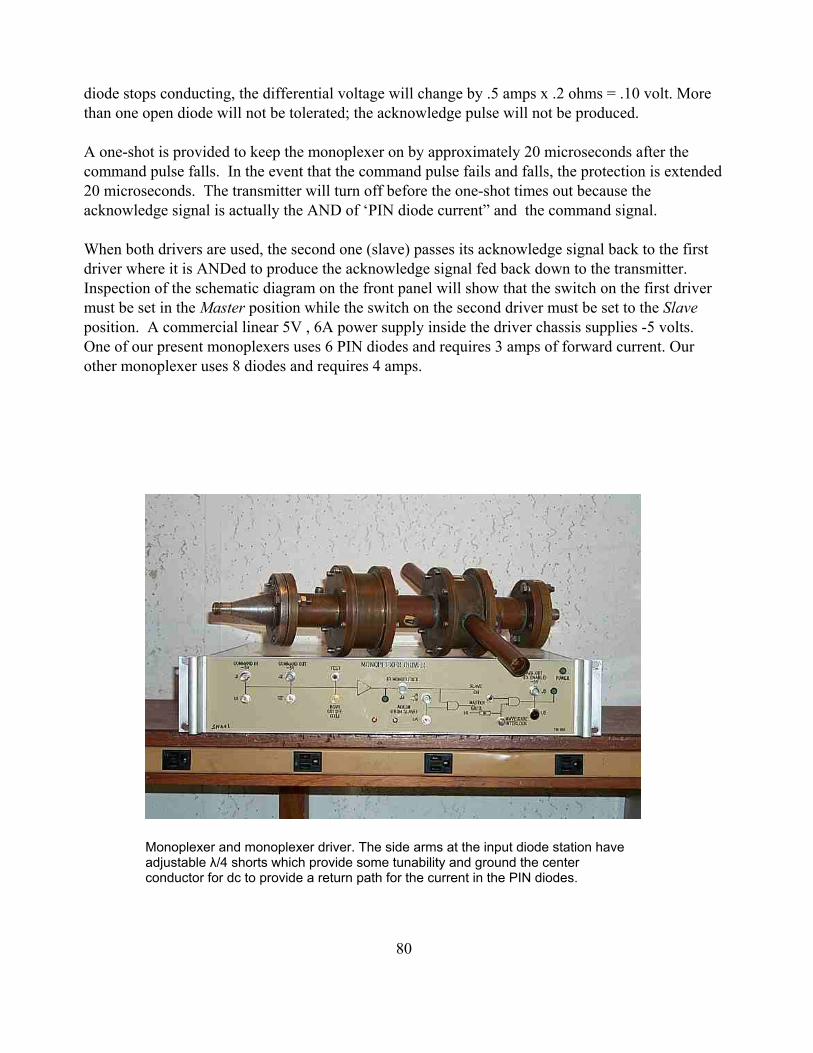
80
Monoplexer and monoplexer driver. The side arms at the input diode station haveadjustable λ/4 shorts which provide some tunability and ground the centerconductor for dc to provide a return path for the current in the PIN diodes.
diode stops conducting, the differential voltage will change by .5 amps x .2 ohms = .10 volt. Morethan one open diode will not be tolerated; the acknowledge pulse will not be produced.
A one-shot is provided to keep the monoplexer on by approximately 20 microseconds after thecommand pulse falls. In the event that the command pulse fails and falls, the protection is extended20 microseconds. The transmitter will turn off before the one-shot times out because theacknowledge signal is actually the AND of ‘PIN diode current” and the command signal.
When both drivers are used, the second one (slave) passes its acknowledge signal back to the firstdriver where it is ANDed to produce the acknowledge signal fed back down to the transmitter.Inspection of the schematic diagram on the front panel will show that the switch on the first drivermust be set in the Master position while the switch on the second driver must be set to the Slaveposition. A commercial linear 5V , 6A power supply inside the driver chassis supplies -5 volts.One of our present monoplexers uses 6 PIN diodes and requires 3 amps of forward current. Ourother monoplexer uses 8 diodes and requires 4 amps.

81
19: Waveguide run to platform, rotary and linear jointsThe waveguide run from the transmitter to the platform is approximately 1300 ft. long and consistsof about 180 flanged sections - straight sections, bends, and corrugated flexible sections. The tablebelow describes the components and their quantities that make up the wave guide run from thetransmitter to the slotted line for the carriage house. This table corresponds to the original system;the addition of the power splitter, the second slotted line, and the half-height waveguide run fromthe dome linear joint to the feed room is not included. (to be done). Note that the length is missingfor some of the components (bends).
SUMMARY OF WAVEGUIDE RUN TO CARRIAGE HOUSESEE DWG. file: waveguide.xls
SYMBOL DESCRIP. LENGTH(IN)
QTY QTY X LENGTH
A STRAIGHT 143.625 85 12208.125B STRAIGHT 125.625 1 125.625C STRAIGHT 68.21875 1 68.21875D STRAIGHT 132.875 1 132.875E STRAIGHT 60 2 120F STRAIGHT 53.5 1 53.5G STRAIGHT 40 1 40H STRAIGHT 108 1 108J STRAIGHT 18 3 54K STRAIGHT 52.5 1 52.5L STRAIGHT 24 1 24M STRAIGHT 57.5625 1 57.5625N STRAIGHT 67 1 67P STRAIGHT 75.75 1 75.75Q STRAIGHT 71 1 71

82
R STRAIGHT 81.25 7 568.75S STRAIGHT 71.75 1 71.75Y STRAIGHT 59.8125 1 59.8125U STRAIGHT 120 1 120V STRAIGHT 16.5 1 16.5W STRAIGHT 47.75 1 47.75X STRAIGHT 68.875 1 68.875Y STRAIGHT 9.625 1 9.625Z STRAIGHT 12.5 1 12.5AA STRAIGHT 12.4375 1 12.4375BB STRAIGHT 9.6875 1 9.6875CC STRAIGHT 13.5 1 13.5DD STRAIGHT 14.125 1 14.125EE STRAIGHT 23.25 1 23.25FF STRAIGHT 1GG STRAIGHT 66.5625 1 66.5625HH STRAIGHT 78 1 78JJ STRAIGHT 32.25 1 32.25
flex FLEX SECTION 16 27 432ZA H BEND (MITER) 15 5 75ZB E BEND (SWEEP) 24 10 240ZC E BEND (SWEEP) 1ZD H BEND (MITRE) 1ZE H BEND (MITRE) 1ZF H BEND (MITER) 3ZG E BEND (SWEEP) 1ZH E BEND (SWEEP) 1ZI E BEND (SWEEP) 1ZJ E BEND (SWEEP) 1ZK E BEND (SWEEP) 1ZL E BEND (SWEEP) 1ZM E BEND (SWEEP) 1
total length in ft 1269.210938no. pcs. 181
Sequence of waveguide components, beginning from the transmitter
(The order is component number; code, component number; code, etc. Note that flex sections arenot numbered).
1 ZA Flex

83
2-3 A, 4 B, 5 ZB, Flex6 A, 7 C, Flex8 ZC, 9-11 A, 12 D, Flex13 ZD, 14-20 A, 21 Zb, 22 E, 23 ZE, Flex24 F, Flex25 ZF, 26 E, Flex27 ZG, 28-30 A, 31 G, 32 A, 33Hj, 34 J, 35-43 A, Flex44 K, 45 A, Flex46 L, 47-49 A, 50 ZH, Flex51-52 A, 53 M, 54 ZB, 55N, 56 Zb, 57 J, 58 ZA, Flex59 P, Flex60 Za, 61 A, Flex62 Q, 63 A, Flex64067 A, Flex68 R, 69-74 A, Flex75 R, 76-81 A, Flex82 S, 83 A, Flex84-85 R, 86-89 A, Flex90 r, 91-96 A, Flex97 R, 98-103 A, Flex104 R, 105-110 A, Flex111-115 A, Flex116 ZB, 117 T, 118 AB, 119 U, 120 ZI, 121 V, 122 A, 123 ZJ, 124 ZB, Flex125 A, 126 W, Flex127 ZB, 128 A, Flex129 ZK,130 ZA, 131 J, 132 ZA, 133-135 A, 136 X, Flex137 ZL, 138 Y, 139 ZRotary Joint140 AA, 141 BB, 142 ZM, 143 CC, 144 AB,145 DD,146 EE 147 EE 148 GG 149 A, 150 HH, 151 ZB, 152 JJ, 153 ZF, Flex154 ZFSlotted line
4 B5 ZBFLEX6 A7 CFLEX
The total length of the waveguide is approximately 1400 ft, depending on the position of thecarriage house. The theoretical loss of 1400 of aluminum WR2100 is 0.48 dB. We measured theloss from the transmitter room to the carriage house to be 1.25 dB, leaving 0.77 dB to be accounted

84
for in the harmonic filter, the corrugated waveguide sections, the rotary joint, the five-probe tuner,the slotted line, and the traveling collector.

85
Waveguide runs above the catwalk fromthe base of tower T12 to the platform.
Half-height transmitter waveguide connection in the dome. For radar operation, thestraight/flex section stowed below the ceiling waveguide run is lowered andbolted into place, connecting the 180-degree bend to the turnstile.
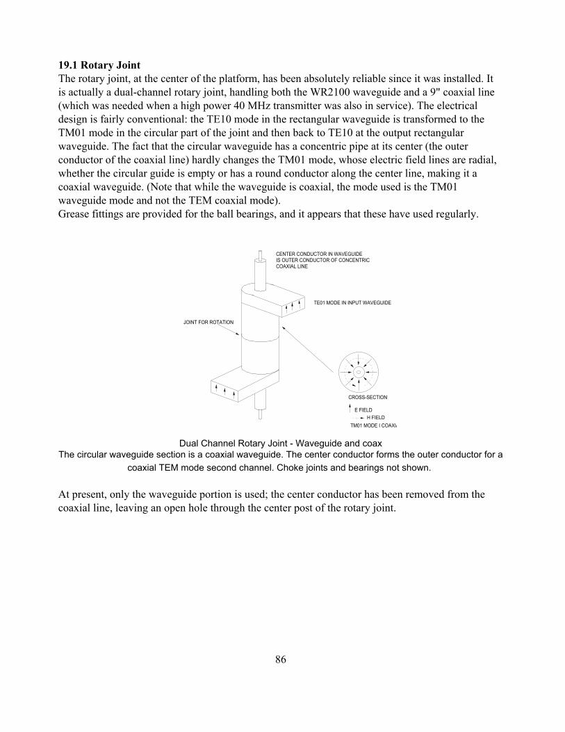
86
JOINT FOR ROTATION
TE01 MODE IN INPUT WAVEGUIDE
E FIELDH FIELD
CROSS-SECTION
TM01 MODE I COAXIA
CENTER CONDUCTOR IN WAVEGUIDEIS OUTER CONDUCTOR OF CONCENTRIC COAXIAL LINE
19.1 Rotary JointThe rotary joint, at the center of the platform, has been absolutely reliable since it was installed. Itis actually a dual-channel rotary joint, handling both the WR2100 waveguide and a 9" coaxial line(which was needed when a high power 40 MHz transmitter was also in service). The electricaldesign is fairly conventional: the TE10 mode in the rectangular waveguide is transformed to theTM01 mode in the circular part of the joint and then back to TE10 at the output rectangularwaveguide. The fact that the circular waveguide has a concentric pipe at its center (the outerconductor of the coaxial line) hardly changes the TM01 mode, whose electric field lines are radial,whether the circular guide is empty or has a round conductor along the center line, making it acoaxial waveguide. (Note that while the waveguide is coaxial, the mode used is the TM01waveguide mode and not the TEM coaxial mode). Grease fittings are provided for the ball bearings, and it appears that these have used regularly.
Dual Channel Rotary Joint - Waveguide and coaxThe circular waveguide section is a coaxial waveguide. The center conductor forms the outer conductor for a
coaxial TEM mode second channel. Choke joints and bearings not shown.
At present, only the waveguide portion is used; the center conductor has been removed from thecoaxial line, leaving an open hole through the center post of the rotary joint.
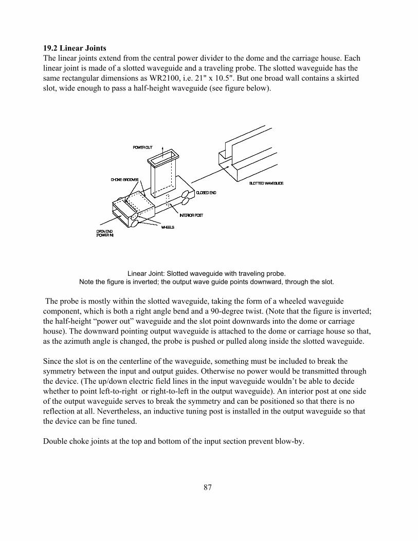
87
19.2 Linear JointsThe linear joints extend from the central power divider to the dome and the carriage house. Eachlinear joint is made of a slotted waveguide and a traveling probe. The slotted waveguide has thesame rectangular dimensions as WR2100, i.e. 21" x 10.5". But one broad wall contains a skirtedslot, wide enough to pass a half-height waveguide (see figure below).
Linear Joint: Slotted waveguide with traveling probe. Note the figure is inverted; the output wave guide points downward, through the slot.
The probe is mostly within the slotted waveguide, taking the form of a wheeled waveguidecomponent, which is both a right angle bend and a 90-degree twist. (Note that the figure is inverted;the half-height “power out” waveguide and the slot point downwards into the dome or carriagehouse). The downward pointing output waveguide is attached to the dome or carriage house so that,as the azimuth angle is changed, the probe is pushed or pulled along inside the slotted waveguide.
Since the slot is on the centerline of the waveguide, something must be included to break thesymmetry between the input and output guides. Otherwise no power would be transmitted throughthe device. (The up/down electric field lines in the input waveguide wouldn’t be able to decidewhether to point left-to-right or right-to-left in the output waveguide). An interior post at one sideof the output waveguide serves to break the symmetry and can be positioned so that there is noreflection at all. Nevertheless, an inductive tuning post is installed in the output waveguide so thatthe device can be fine tuned.
Double choke joints at the top and bottom of the input section prevent blow-by.

88
Collector (upside down) Main body and output stack are half-height waveguide. Input scoop is a λ/4 matchingtransformer. Choke joint cavities attop and bottom of scoop prevent blow-by.
Collector rolls on polypropylene wheelsinside slotted waveguide. Wheel well reflections are canceled with hockey puckpost.
Unpacking the collector (the moving partof the linear joint).
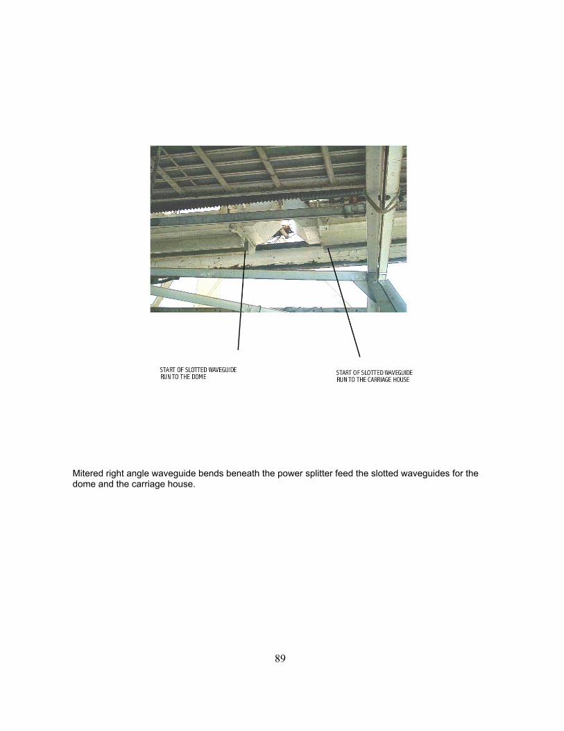
89
Mitered right angle waveguide bends beneath the power splitter feed the slotted waveguides for thedome and the carriage house.

90
19.3 Waveguide ReflectionsIn most transmitter/feed line/antenna situations, care is taken to eliminate standing waves, in orderto avoid extra feed line loss or voltage breakdown. Feed line loss is usually not a problem; for afixed amount of radiated power, a VSWR of 2:1 only increases a line’s loss by 1/8 over the losswith a perfect 1:1 VSWR. Our system should normally have a VSWR lower than 2:1. As forbreakdown, our WR2100 waveguide sections can handle many tens of megawatts, but some othercomponents, such as the linear joints, operate with much lower margins, which is one reason for usto keep standing waves low. Another reason is that the klystrons can be damaged by quite smallamounts of reflected power. The EH tuner at the transmitter output lets us present the klystrons witha reflectionless load - as long as the feed is at a fixed azimuth angle. However, an reflectionsproduced out past the linear joint will change in phase as the feed moves along the azimuth arm.Thus the EH tuner would have to be adjusted continuously if the azimuth angle is changing - not apractical solution.
Most of our waveguide system consists of straight sections, gentle curves, and tuned miter bends,which should be essentially reflectionless. The potential spots for reflection are the rotary joint, thetransition from straight waveguide into slotted waveguide, the “collector” that travels in the slottedguide, and the turnstile/feed antenna combination. The collectors have been carefully tuned in thelab to minimize reflection, since any reflection from them will change in phase as the collectormoves, as explained above. For the same reason, the reflection from the turnstile/horn should bemade as small as possible. Simple tuners in the carriage house and dome would permit this, but arenot used at present. The only tuner on the platform is a 5-stub tuner at the transition from thestandard waveguide to the slotted waveguide.
Note also that our system is not equipped with a directional coupler at the downstairs end of thewaveguide, just after the EH tuner. Such a coupler should be installed as a monitor, so we canreadily detect the presence of a large reflected wave, as would be produced, for example, by abroken flex section.
19.4 5-Probe TunerThe 5-probe tuner (at the input to the slotted waveguide) consists of a length of waveguide havingfive capacitive probes, mounted at intervals of about 3/8 λ. Moderate amounts of reflection can beeliminated with such a device with only modest penetration of each probe, so the device can handlehigh power. (Textbook double probe tuners can require very large insertion depths to cancel onlysmall reflections and thus have limited power handling capability). Considering the action of thistuning device as plotted on a Smith Chart, it seems that one can use the following tuning procedure:Begin with all the probes withdrawn. Then, starting at the load end, each probe is adjusted insequence to minimize the reflection as seen at the input. If the reflection happens to be equivalent toa shunt capacitance at the load end, the first probe will be left all the way out.

91
In
Out1
Out2
Shorting "buckets"Yoke
Section 20: Platform power dividerThis 3-port device is a junction between the transmitter waveguide from downstairs, the waveguidegoing to the Gregorian dome, and the waveguide going to the carriage house. It provides aninfinitely variable splitting ratio; any desired fraction, f, of the power can be sent to the dome andthe remainder, (1-f), will go to the carriage house. As long as there are no reflections in the domeand carriage house waveguides, the splitter will present a matched load to transmitter waveguide.Figure 20.1 shows how two adjustable shorts are used to control the power division ratio.
Caution: When the splitter is set at one extreme, so that the power goes nominally just to thecarriage house, we still take the precaution of bolting a plate over the open waveguide as it entersthe dome. Note that the waveguide run between the splitter and this plate will act as a high Qresonant cavity if its electrical length, as determined by the position of the dome along the elevationrail, is an odd number of quarter wavelengths. In this case, even with the splitter set for the carriagehouse, a large standing wave can be present in the this line. Workers near the slotted part of the linecould be exposed to excessive radiation. This is one of the reasons that personnel should be off theplatform when the 430 radar is running..
Figure 20.1 Infinitely-Variable Waveguide Power Splitter

92
This splitter is made of so-called waveguide series Tees ( E-plane Tees). If one imagines thewaveguides to be parallel wire transmission lines, with the wires running down the centers of thebroad walls, these T’s can be seen to be series rather than shunt connections. An equivalent circuitis shown below in Figure 20.2, with ordinary open wire transmission lines in place of thewaveguide sections.
Power splitter and 5-probe tuners amid structural beams on the platform.

93
0 + 90 DEG
0
90 DEG.
90 DEG.SHORTS
Zo
Zo
Zin Z1Z2
Figure 20.2 Equivalent Transmission Line Circuit
Looking at the figure, we see that the input impedance is the sum of Z1 and Z2 because of the seriesconnection of the input T. Each of the arms is a 90-degree section, terminated by a load in serieswith a stub. The impedance of the bottom arm’s termination is therefore Zo + j Zo tan (θ) and theimpedance of the top arm’s termination is Zo + j Zo tan (θ+90). The impedances Z1 and Z2 are thereciprocals of the top and bottom termination impedances, inverted by the 90-degreesections of line. Thus we can write
Zin ' Z1 % Z2 '
Zo1& jcotθ
%Zo
1 % j tan(θ)' Zo, 1)
where we have used the identity tan (θ+90) = - cot (θ ). Note that Zin is identically equal to Zo forany value of theta; the device presents a perfect match.
Since the input impedance is constant, independent of theta, the current will be independent oftheta. The power delivered to the top and bottom leads will be proportional to the real parts of Z1and Z2. Thus we can write
P1 % 11% cot2θ
' cos2θ 2)
and
P2 % 11% tan2θ
' sin2θ. 3)

94
0 0.5 1 1.50
0.5
1
sin θ( )2
cos θ( )2
θ
.
which are plotted below in Figure 20.3
Figure 20.3 Dome and Carriage House power vs. power divider’s short position

95
21.000
TX PORT
RCVR PORT
5.000
2.500 11.567
Ø18.500
Ø12.000
Ø8.500Ø2.000
5.000
A
SECTION "A'
10.500
0.250
13.812
3.812
20.500
LHC
21.000
A
LCP TO LINE FEED jbh 11-15-00
CARRIAGE HOUSE TURNSTILE file: tstlfig.ecw
PORT 1 (RECEIVER)
PORT 3 (SHORT) PORT 4 (SHORT)
PORT 2 TRANSMITTER
21. Turnstile Junctions (passive diplexers)21.1 Basic operationThe transmitter waveguide connects to one of the four side ports of the turnstile junction.The adjacent side ports are terminated with shorts whose lengths differ by λguide/4. Power flowinginto the transmitter port exits entirely form the circular waveguide port and is circularly polarized.(i.e. the two orthogonal TE11 output waves differ in phase by 90 degrees). None (ideally) of thetransmitter power leaks out the receiver port, so the receiver will not vaporize. The circularwaveguide is connected directly to the feed horn (at the dome side) or to the line feed (at thecarriage house side). Return signals (echos from the ionosphere or from other single reflectiontargets) will have the opposite sense of circular polarization. As they enter the turnstile from thecircular waveguide, their power is steered entirely to the receiver port (the side port opposite thetransmitter port).
In practice it is impractical to achieve more than 25 or 30 dB isolation between transmitter andreceiver ports. With 25 dB isolation and 2.5 MW into the transmitter port, 7905 watts will exit thereceiver port, so additional receiver protection is needed. This protection is provided by a PINdiode monoplexer, which, when forward biased by the monoplexer driver, effectively shorts thetransmission line into the receiver, reflecting the several 7.9 kilowatts of leakage back into theturnstile junction before it can reach the receiver.

96
PORT 4 (SHORT)
PORT 2 TRANSMITTER
"PORT 6"
"PORT 5"
PORT 3 (SHORT)
PORT 1 (RECEIVER)
21.2 Theory of turnstile operationThe device was invented and patented by Robert H. Dicke, who fully described its operation
in Principles of Microwave Circuits, R.H. Dicke and E. M. Purcell, Rad Lab Series, Volume 8. The circular port supports two orthogonal modes, these modes are indicated on figure below as“Port 5 and “Port 6". (The arrows indicate the electric field direction for these modes. At therectangular ports, there is only one mode possible, and its electric field is perpendicular to the broadwall of the guide). If one begins with the bare turnstile, i.e. the rectangular and circular waveguidesstructure, it will be found that power applied to a side port will appear at the other side ports andalso at Port 5 or Port 6.(Note, for example, thatfrom symmetry, powerapplied to Port 1 cannotexit Port 5). However, onecan “tune” the device byinserting a structure ofconcentric posts, asshown in the precedingfigure. With theappropriate tuningstructure, the junction willhave the followingproperties:
1. All ports will bematched, i.e. none of thepower incident on any port will be reflected, providing the other ports are connected to matchedloads.
2. Power incident on a side port will split three ways: 25% will flow to each adjacentside port and 50% will flow to either Port 5, or Port 6, as explained above. The opposite side port isisolated: no power flows to it..
Suppose we have built and tuned a turnstile junction. We now install shorts on the two unusedsidearms and we make the length of these shorts differs by 90 degrees. Now we apply power to thetransmitter port. Half this power proceeds out Port 6, as discussed above. One quarter of the powergoes to each shorted side port and is reflected back into the turnstile. The reflections, as they reenterthe turnstile, differ in phase by 180 degrees, due to the round trip through the 90-degree pathdifference. Thus the reflected waves cancel at both the transmitter port and at the receiver port(maintaining the isolation of the receiver). But each reflection also sends half of its power into Port5. These voltages are in phase, so the total power arriving at Port 5 is equal to half the transmitterpower.In summary, the installation of the shorts on the sidearms has transformed the 6-port turnstile into a4-port diplexer.

97
TRANSMITTER PORT
SHORT SHORT
LONG SHORT
FROM TRANSMITTER
TO LOAD
LONG SHORT(1/4 X GUIDE WAVELENGTH)
X
Y
INPUT PLANE
SHORT SHORT(ZERO LENGTH)
LEFT SIDE PLANE
TURNSTILE, AS VIEWED LOOKING INTO THECIRCULAR PORT.
FILE: circpol.ecw
SECONDARY
PRIMARY
LHC
RHC
RHCLHC
TERTIARY
21.3 Length of the turnstile side shorts So far, the only requirement placed on the side shorts is that their electrical lengths differ by 90degrees. But, for the device to act as a “self diplexer”, the output wave must have circularpolarization, i.e. the phase of the wave leaving Port 5 must differ by 90 degrees from the waveleaving Port 6. This is the same as saying that the wave entering Port 3, after being reflected fromthe side short at that port, differ in phase by 90 (or 270) degrees from the phase incident on Port 2,the transmitter port. If we know the the phase path, in degrees, between the transmitter port and anadjacent side port (i.e. the phase path between any two adjacent side ports), we can calculate theabsolute lengths for the shorts. This phase path can be measured directly with a network analyzeror calculated using a finite element modeling program. If we do not know this phase path, we canfit the turnstile with adjustable shorts. The adjustment procedure would be first to set one short atan arbitrary position, say fully in, and set the other short farther out by λguide/4. We can verify thatthe separation is correct by noting that feed through to the receiver port is minimized. Next we varythe positions of the shorts, while maintaining the λguide/4 difference, to circularize the polarizationleaving the circular waveguide. One way to do this is to put a metal cap over the circularwaveguide. The cap provides a totally reflecting short which will change the sense of the circularpolarization, causing the reflection to leave via the receiver port. If we put a matched load on thereceiver port, we simply adjust the shorts until there is no reflection seen at the transmitter port.
21.4 Sense of the polarization: right-hand circular or left-hand circular? The turnstile picturedbelow, produces left-circular polarization. After reflections from the tertiary, secondary, andprimary mirrors, the radiated polarization is right-circular.

98
Dome turnstile junction. Side ports are half-heightwaveguide. Side shorts are fixed. Note concentric posttuning structure.
We consider the polarization of the wave coming out of the turnstile. We will take the phase of they-component to be the phase at the input plane. In our S-band turnstile, the phase path from theinput plane to the left side plane is almost exactly 270 degrees, as shown by lab measurements andby HFSS simulation. The wave making this left turn is then shifted another 180 degrees when itreflects from the short. The total phase of the x-component is therefore 270+180 = 90 degrees.Expressing the x and y components, we have
Ex = Re (ejωt-π/2) = cos(ωt-π/2) = sin(ωt)
Ey = Re(ejωt ) = cos(ωt)
The E vector, as seen when the wave is approaching us, thus rotates in the clockwise direction. (Ast increases from zero, Ex goes from zero to a positive number while Ey begins to decrease). Bydefinition (IRE, IEEE) this is left-circular polarization. The tertiary, secondary, and primaryreflectors each reverse the polarization so the telescope finally transmits right-circular polarization.

99
22. Safety and protection systems. Section 22.1 discusses personnel safety. Section 22.2 discusses the circuitry to protect thetransmitter itself.
22.1.1 Personnel Safety systems & hazards: high-voltage, radiation, X-ray, ChemicalWith its high-voltage, high-power, and high places, this transmitter is potentially lethal.Appropriate precautions must be taken to avoid electrical shock and radiation exposure - both RFand X-ray. Chemical hazards are less likely; the original PCB capacitors have been replaced bynon-PCB capacitors, amd the oil in the modulator tank has always been mineral oil. Nevertheless,this oil, (Texaco codigo 1515 transformer oil) runs at a high temperature, over 120 F, and with thevery large exposed surface, gives off enough vapor to cause uncomfortable lung irritation. Noberyllium oxide ceramics are used in the klystrons or other tubes, but, in any event, these tubes arenever opened and even accidental breakage would not likely produce any beryllium oxide dust. 22.1.2 High voltage vault
The high-voltage vault contains the 100,000-volt dc power supply, the capacitor bank, themodulator, the crowbar and crowbar trigger generator, and other associated transformers and switchgear. Except for a roll-up door to the outside, which can only be opened from the inside, there isonly one entrance to the high-voltage vault. This entry door has a small window which provides aview of the obviously hazardous high-voltage equipment. The key that opens this door is the samekey (attached to a large metal tag) that must be inserted in the lock switch on the console to operatethe transmitter. Interlock circuitry allows the transmitter to operate only when the vault door istightly closed and the tagged key is installed in the console. While the door is open, the tagged keycannot be removed from the door lock. The door lock actually has two keys, side by side. Both keysare needed to lock the door. When an engineer or technician is working in the vault, he may want tokeep the second (untagged) key in his pocket to prevent anyone from accidentally locking himinside the vault and turning on the transmitter.
22.1.3 Entering the high voltage vaultAs explained above, the transmitter will normally be off before the vault door is opened,
simply because the key to open the door can only be removed from the conose when the consoleswitch is in the off position. Moreover, when the transmitter is off, metal bars in the high voltagevault drop down to maintain a short-circuit on the capacitor bank, eliminating the most obvioushigh-voltage hazard. Even without the shorting bars, the two bleeder resistor stacks across thecapacitor banks will discharge it in a few minutes. Nevertheless, one must always assume that theseprotection devices may have failed. Therefore, upon opening the door, always grasp the insulatedhandle of the tethered shorting bar (shorting cane) and touch its hooked metal tip to Point #1, themetal corona ball at the top of the high-voltage metering tower (the tower nearest the door). No arcshould result. Leave the cane hooked to the top coronal ball. Take the second (longer) shorting canefrom the floor, proceed into the vault and touch the metal tip of the cane to Point #2, the highvoltage bus (the tubular aluminum rail that runs around the capacitor bank). Again, no arc shouldresult (note that the rail and the corona ball are part of the same aluminum structure). Touch thiscane to the lower corona ring (Point #3) and the upper corona ring (Point #4). Leave this cane

100
hooked to the upper corona ring. Remember to unhook both shorting canes before exiting andlocking the vault.
22.1.4 Capacitor bank safetyEach of the 248 capacitors is connected to the high voltage bus by a 1000-ohm, 100 watt
resistor. When one of these resistors must be removed for cleaning or replacement, it should beassumed that the resistor may have become an open circuit, leaving the capacitor charged anddangerous. Therefore, before touching one of these resistors, touch the tip of one of the tetheredshorting canes to the capacitor terminal. Remember also that a nominally discharged capacitor may,when disconnected, develop a hazardous voltage due to dielectric absorption. Therefore, beforeremoving the resistor, connect a shorting wire from the capacitor terminal to the capacitor bankframe. Leave this wire in place until the resistor or its replacement has been reinstalled.
22.1.5 Modulator safetyThe modulator is totally enclosed by its steel tank and presents no hazard until the tank-top
doors are lifted open. When the modulator must be worked on, lift both doors. (The left-hand dooris over the Buffer Deck and the right-hand door is over the Floating Deck). When the oil level has been pumped down to reveal the decks, clip a jumper from ground (thetank) to the Buffer Deck chassis and another jumper from ground to the Floating Deck Chassis.Keep a grounding cane ready ground any point that will be touched in the course of changing oradjusting a component. Touch the grounding cane to every exposed point, especially if you will beclimbing into the tank. Also, before entering the tank, turn off the transmitter's main power switch(large brown box on the wall outside the vault) to be doubly sure that the ac prime power is notpresent. Remember that both decks contain numerous capacitors. Every capacitor is supposed tohave a bleeder resistor. Nevertheless, bleeders might be open or even missing. If touching thegrounding cane to any point draws a spark, use the schematic diagrams to determine whichcapacitor still had charge and replace the corresponding bleeder. The characteristics and safteyinformation for the Texaco 1515 transformer oil is attached to the end of this section.
22.1.6 Crowbar safetyThe crowbar circuit produces a high-voltage pulse on the sharp probe between the two
discharge balls. When the transmitter is off, a high-voltage vacuum relay grounds the plate of the5C22 Thyratron tube, used to produce this pulse. Nevertheless, before working on the crowbarcircuit, use grounding canes and jumpers to ensure that no capacitors remain charged.
22.1.7 X-ray hazardsBecause the high-voltage supply produces up to 120,000 volts, X-rays can be produced in
by the klystrons. For this reason, the klystron vault is shielded with slabs of lead. Still,measurements have shown that some radiation is present outside the vault at the top and bottomends of the tubes. Radiation hazard warning stickers are placed on the klystron vault near the doorof the high-voltage vault and on the mezzanine, near the top of the klystron vault. Stay clear ofthese areas when the transmitter is in operation.

101
22.1.8 RF radiation hazardsNo hazardous RF radiation levels should exist near the transmitter. All the RF energy
should be confined inside the klystrons and inside the waveguide transmission line. Of course,periodic tests should be made with the NARDA radiation detector to be sure that none waveguideplumbing is leaking from cracks or loose flanges. When the line feed was the only transmitter feed,we allowed personnel to work on the platform, except around the top of the carriage house near thecollector, where the excessive RF fields were measured. Now, with the dual beam system(transmission possible from both the carriage house and the dome), personnel are not allowed onthe platform while the transmitter is in use, no matter whether the dome feed is in use or not.There is considerable spill over from the horn in the dome, producing large fields inside and evenabove the dome. Even if all the power is being steered to the carriage house, the design of thepower splitter allows large standing waves to build up in slotted waveguide nominally not in use,depending on the position of the dome. When bolt-in transmitter waveguide section is not installedin the dome, we take the precaution of bolting a plate over transmitter end of the gap. Note that thewaveguide run between the splitter and this plate will act as a high Q resonant cavity if its electricallength, as determined by the position of the dome along the elevation rail, is an odd number ofquarter wavelengths. In this case, even with the splitter set for the carriage house, a large standingwave can be present in the this line. Workers near the slotted part of the line could be exposed toexcessive radiation. This is one of the reasons that personnel must be off the platform, no matter themode of operation.
22.2 Transmitter Protection Systems22.2.1 Arc Detectors (See Section 12.2)22.2.2 Reflected Power Alarm (See section 12.2)
The Reflected Power Alarm is misnamed, in that its primary function is to remove theklystron RF drive as soon as excessive reflected power is sensed at the output of either klystron. Asecond TTL signal (normally low) is provided to actuate an audible alarm..
Refer to the schematic diagram “Reflected Power and Arc Alarm Shut-off”. Reflectedpower is sensed by 50 dB directional couplers at the output of each klystron. These signals arefurther attenuated by a 2 dB pads and also by cable loss between the mezzanine and the console.Diode detectors in the console provide dc signals for the two sensing circuits in the console-mounted Reflected Power and Arc Alarm Shut-off chassis. These circuits are straightforward: thedetected signal, a negative voltage, feeds current into the summing point of a conventional invertingop amp. A local positive bucking current is adjusted so that the output of the op amp remainsnegative unless the reflected power increases. BNC monitor ports are provided so that the operatorcan see how closely the op amp outputs approach zero. Comparators follow the op amps; anypositive excursion triggers a comparator and latches a flip-flop. The flip-flops for the twocomparators are ORed to form the output signal. A front panel push button is provided to reset theflip-flops. A “Test” button is provided to inject a signal equivalent to a -3V signal from thedetectors (roughly the signal expected when the reflected power is 15 dB below 1MW of forwardpower).

102
22.2.3 CrowbarThe Crowbar circuit is described in Section 12. Note that this circuit, by itself, can be
lethal. Use appropriate care when servicing it; use temporary jumpers across high voltagecapacitors.

103
22.2.4MSDS for the Texaco 1515 mineral oil used in the modulator tank Material Safety Data Sheet
24-Hour Emergency Telephone Numbers HEALTH : ChevronTexaco Emergency Information Center (800) 231-0623 or (510) 231-0623 TRANSPORTATION : CHEMTREC (800) 424-9300 or (703) 527-3887 Emergency Information Centers are located in the U.S.A. International collect calls accepted.
SECTION 1 PRODUCT AND COMPANY IDENTIFICATION
TEXACO Transformer Oils
Product Number(s): 00600, 01515, CPS220600, CPS221515 Synonyms: TEXACO Transformer Oil, TEXACO Transformer Oil Inhibited
Company Identification ChevronTexaco Global Lubricants 6001 Bollinger Canyon Road San Ramon, CA 94583 United States of America
Product Information Product Information: 800-LUBE-TEK email : [email protected]
SECTION 2 COMPOSITION/ INFORMATION ON INGREDIENTS
COMPONENTS CAS NUMBER AMOUNT
Distillates, hydrotreated light naphthenic 64742-53-6 40 - 60 %weight
Distillates, hydrotreated middle 64742-46-7 40 - 60 %weight
SECTION 3 HAZARDS IDENTIFICATION
IMMEDIATE HEALTH EFFECTS Eye: Not expected to cause prolonged or significant eye irritation. Skin: Contact with the skin is not expected to cause prolonged or significant irritation. Contact with the skin isnot expected to cause an allergic skin response. Not expected to be harmful to internal organs if absorbedthrough the skin.

104
Ingestion: Not expected to be harmful if swallowed. Inhalation: Not expected to be harmful if inhaled. Contains a petroleum-based mineral oil. May causerespiratory irritation or other pulmonary effects following prolonged or repeated inhalation of oil mist at airbornelevels above the recommended mineral oil mist exposure limit. Symptoms of respiratory irritation may includecoughing and difficulty breathing.
SECTION 4 FIRST AID MEASURES
Eye: No specific first aid measures are required. As a precaution, remove contact lenses, if worn, and flusheyes with water. Skin: No specific first aid measures are required. As a precaution, remove clothing and shoes ifcontaminated. To remove the material from skin, use soap and water. Discard contaminated clothing and shoesor thoroughly clean before reuse. Ingestion: No specific first aid measures are required. Do not induce vomiting. As a precaution, get medicaladvice. Inhalation: No specific first aid measures are required. If exposed to excessive levels of material in the air,move the exposed person to fresh air. Get medical attention if coughing or respiratory discomfort occurs.
SECTION 5 FIRE FIGHTING MEASURES
FIRE CLASSIFICATION: OSHA Classification (29 CFR 1910.1200): Not classified by OSHA as flammable or combustible.
NFPA RATINGS: Health: 0 Flammability: 1 Reactivity: 0
FLAMMABLE PROPERTIES: Flashpoint: (Cleveland Open Cup) 295 °F (146 °C) (Min) Autoignition: NDA Flammability (Explosive) Limits (% by volume in air): Lower: NDA Upper: NDA
EXTINGUISHING MEDIA: Use water fog, foam, dry chemical or carbon dioxide (CO2) to extinguish flames.
PROTECTION OF FIRE FIGHTERS: Fire Fighting Instructions: This material will burn although it is not easily ignited. For fires involving thismaterial, do not enter any enclosed or confined fire space without proper protective equipment, including self-contained breathing apparatus. Combustion Products: Highly dependent on combustion conditions. A complex mixture of airborne solids,liquids, and gases including carbon monoxide, carbon dioxide, and unidentified organic compounds will beevolved when this material undergoes combustion.
SECTION 6 ACCIDENTAL RELEASE MEASURES
Protective Measures: Eliminate all sources of ignition in vicinity of spilled material. Spill Management: Stop the source of the release if you can do it without risk. Contain release to preventfurther contamination of soil, surface water or groundwater. Clean up spill as soon as possible, observing

105
precautions in Exposure Controls/Personal Protection. Use appropriate techniques such as applying non-combustible absorbent materials or pumping. Where feasible and appropriate, remove contaminated soil. Placecontaminated materials in disposable containers and dispose of in a manner consistent with applicableregulations. Reporting: Report spills to local authorities and/or the U.S. Coast Guard's National Response Center at (800)424-8802 as appropriate or required.
SECTION 7 HANDLING AND STORAGE
General Handling Information: Avoid contaminating soil or releasing this material into sewage and drainagesystems and bodies of water. Static Hazard: Electrostatic charge may accumulate and create a hazardous condition when handling thismaterial. To minimize this hazard, bonding and grounding may be necessary but may not, by themselves, besufficient. Review all operations which have the potential of generating an accumulation of electrostatic chargeand/or a flammable atmosphere (including tank and container filling, splash filling, tank cleaning, sampling,gauging, switch loading, filtering, mixing, agitation, and vacuum truck operations) and use appropriate mitigatingprocedures. For more information, refer to OSHA Standard 29 CFR 1910.106, 'Flammable and CombustibleLiquids', National Fire Protection Association (NFPA 77, 'Recommended Practice on Static Electricity', and/orthe American Petroleum Institute (API) Recommended Practice 2003, 'Protection Against Ignitions Arising Outof Static, Lightning, and Stray Currents'. Container Warnings: Container is not designed to contain pressure. Do not use pressure to empty containeror it may rupture with explosive force. Empty containers retain product residue (solid, liquid, and/or vapor) andcan be dangerous. Do not pressurize, cut, weld, braze, solder, drill, grind, or expose such containers to heat,flame, sparks, static electricity, or other sources of ignition. They may explode and cause injury or death. Emptycontainers should be completely drained, properly closed, and promptly returned to a drum reconditioner ordisposed of properly.
SECTION 8 EXPOSURE CONTROLS/PERSONAL PROTECTION
GENERAL CONSIDERATIONS: Consider the potential hazards of this material (see Section 3), applicable exposure limits, job activities, andother substances in the work place when designing engineering controls and selecting personal protectiveequipment. If engineering controls or work practices are not adequate to prevent exposure to harmful levels ofthis material, the personal protective equipment listed below is recommended. The user should read andunderstand all instructions and limitations supplied with the equipment since protection is usually provided fora limited time or under certain circumstances.
ENGINEERING CONTROLS: Use in a well-ventilated area.
PERSONAL PROTECTIVE EQUIPMENT Eye/Face Protection: No special eye protection is normally required. Where splashing is possible, wear safetyglasses with side shields as a good safety practice. Skin Protection: No special protective clothing is normally required. Where splashing is possible, selectprotective clothing depending on operations conducted, physical requirements and other substances in theworkplace. Suggested materials for protective gloves include: Nitrile Rubber, Viton. Respiratory Protection: No respiratory protection is normally required. If user operations generate an oil mist, determine if airborne concentrations are below the occupational exposure

106
limit for mineral oil mist. If not, wear an approved respirator that provides adequate protection from themeasured concentrations of this material. For air-purifying respirators use a particulate cartridge. Use a positive pressure air-supplying respirator in circumstances where air-purifying respirators may not provideadequate protection.
Occupational Exposure Limits:
Component Limit TWA STEL Ceiling Notation
Distillates, hydrotreated lightnaphthenic
OSHA_PEL 5 mg/m3
Distillates, hydrotreated lightnaphthenic
ACGIH_TLV 5 mg/m3 10 mg/m3
Distillates, hydrotreated lightnaphthenic
ACGIH 5 mg/m3 10 mg/m3
SECTION 9 PHYSICAL AND CHEMICAL PROPERTIES
Attention: the data below are typical values and do not constitute a specification.
Color: Colorless Physical State: Liquid Odor: Petroleum odor pH: NA Vapor Pressure: NDA Vapor Density (Air = 1): >1 Boiling Point: >392 F (>200 °C) Solubility: Soluble in hydrocarbons; insoluble in water Freezing Point: NA Melting Point: NDA Specific Gravity: 0.88 @ 15.6 °C / 15.6 °C Viscosity: 8.8 cSt @ 40 °C (Typical) Evaporation Rate:
SECTION 10 STABILITY AND REACTIVITY
Chemical Stability: This material is considered stable under normal ambient and anticipated storage andhandling conditions of temperature and pressure. Incompatibility With Other Materials: May react with strong oxidizing agents, such as chlorates, nitrates,peroxides, etc. Hazardous Decomposition Products: None known (None expected) Hazardous Polymerization: Hazardous polymerization will not occur.

107
SECTION 11 TOXICOLOGICAL INFORMATION
IMMEDIATE HEALTH EFFECTS Eye Irritation: The eye irritation hazard is based on evaluation of data for similar materials or productcomponents. Skin Irritation: The skin irritation hazard is based on evaluation of data for similar materials or productcomponents. Skin Sensitization: The skin sensitization hazard is based on evaluation of data for similar materials or productcomponents. Acute Dermal Toxicity: The acute dermal toxicity hazard is based on evaluation of data for similar materialsor product components. Acute Oral Toxicity: The acute oral toxicity hazard is based on evaluation of data for similar materials orproduct components. Acute Inhalation Toxicity: The acute inhalation toxicity hazard is based on evaluation of data for similarmaterials or product components.
ADDITIONAL TOXICOLOGY INFORMATION: This product contains petroleum base oils which may be refined by various processes including severe solventextraction, severe hydrocracking, or severe hydrotreating. None of the oils requires a cancer warning under theOSHA Hazard Communication Standard (29 CFR 1910.1200). These oils have not been listed in the NationalToxicology Program (NTP) Annual Report nor have they been classified by the International Agency forResearch on Cancer (IARC) as; carcinogenic to humans (Group 1), probably carcinogenic to humans (Group2A), or possibly carcinogenic to humans (Group 2B).
SECTION 12 ECOLOGICAL INFORMATION
ECOTOXICITY The toxicity of this material to aquatic organisms has not been evaluated. Consequently, this material shouldbe kept out of sewage and drainage systems and all bodies of water.
ENVIRONMENTAL FATE This material is not expected to be readily biodegradable.
SECTION 13 DISPOSAL CONSIDERATIONS
Oil collection services are available for used oil recycling or disposal. Place contaminated materials incontainers and dispose of in a manner consistent with applicable regulations. Contact your sales representativeor local environmental or health authorities for approved disposal or recycling methods.
SECTION 14 TRANSPORT INFORMATION
The description shown may not apply to all shipping situations. Consult 49CFR, or appropriate DangerousGoods Regulations, for additional description requirements (e.g., technical name) and mode-specific or quantity-
108
specific shipping requirements.
DOT Shipping Name: NOT REGULATED AS A HAZARDOUS MATERIAL FOR TRANSPORTATION UNDER49 CFR DOT Hazard Class: NOT APPLICABLE DOT Identification Number: NOT APPLICABLE DOT Packing Group: NOT APPLICABLE Additional Information: NOT HAZARDOUS BY U.S. DOT. ADR/RID HAZARD CLASS NOT APPLICABLE.
SECTION 15 REGULATORY INFORMATION
SARA 311/312 CATEGORIES: 1. Immediate (Acute) Health Effects: NO 2. Delayed (Chronic) Health Effects: NO 3. Fire Hazard: NO 4. Sudden Release of Pressure Hazard: NO 5. Reactivity Hazard: NO
REGULATORY LISTS SEARCHED:
4_I1=IARC Group 1 15=SARA Section 313
4_I2A=IARC Group 2A 16=CA Proposition 65
4_I2B=IARC Group 2B 17=MA RTK
05=NTP Carcinogen 18=NJ RTK
06=OSHA Carcinogen 19=DOT Marine Pollutant
09=TSCA 12(b) 20=PA RTK
No components of this material were found on the regulatory lists above.
CHEMICAL INVENTORIES: AUSTRALIA: All the components of this material are listed on the Australian Inventory of Chemical Substances(AICS). CANADA: All the components of this material are on the Canadian DSL or have been notified under the NewSubstance Notification Regulations, but have not yet been published in the Canada Gazette. PEOPLE'S REPUBLIC OF CHINA: All the components of this product are listed on the draft Inventory of ExistingChemical Substances in China. EUROPEAN UNION: All the components of this material are in compliance with the EU Seventh AmendmentDirective 92/32/EEC.

109
JAPAN: All the components of this product are on the Existing & New Chemical Substances (ENCS) inventoryin Japan, or have an exemption from listing. KOREA: All the components of this product are on the Existing Chemicals List (ECL) in Korea. PHILIPPINES: All the components of this product are listed on the Philippine Inventory of Chemicals andChemical Substances (PICCS). UNITED STATES: All of the components of this material are on the Toxic Substances Control Act (TSCA)Chemical Inventory.
NEW JERSEY RTK CLASSIFICATION: Under the New Jersey Right-to-Know Act L. 1983 Chapter 315 N.J.S.A. 34:5A-1 et. seq., the product is to beidentified as follows: PETROLEUM OIL (Lubricating oil) WHMIS CLASSIFICATION: This product is not considered a controlled product according to the criteria of the Canadian Controlled ProductsRegulations.
SECTION 16 OTHER INFORMATION
NFPA RATINGS: Health: 0 Flammability: 1 Reactivity: 0 HMIS RATINGS: Health: 0 Flammability: 1 Reactivity: 0
(0-Least, 1-Slight, 2-Moderate, 3-High, 4-Extreme, PPE:- Personal Protection Equipment Index recommendation,*- Chronic Effect Indicator). These values are obtained using the guidelines or published evaluations preparedby the National Fire Protection Association (NFPA) or the National Paint and Coating Association (for HMISratings).
REVISION STATEMENT: This is a new Material Safety Data Sheet.
ABBREVIATIONS THAT MAY HAVE BEEN USED IN THIS DOCUMENT:
TLV - Threshold Limit Value TWA - Time Weighted Average
STEL - Short-term Exposure Limit PEL - Permissible Exposure Limit
CAS - Chemical Abstract Service Number
NDA - No Data Available NA - Not Applicable
<= - Less Than or Equal To >= - Greater Than or Equal To
Prepared according to the OSHA Hazard Communication Standard (29 CFR 1910.1200) and theANSI MSDS Standard (Z400.1) by the ChevronTexaco Energy Research & Technology Company,

110
100 Chevron Way, Richmond, California 94802.

111
22.4.5Testing the modulator oil for voltage breakdown: fromhttp://www.nttworldwide.com/tech2208.htm
Dielectric Breakdown VoltageBackground:
The dielectric breakdown voltage is a measure of an insulating fluids ability to withstand a highelectric field stress without breaking down. It can also indicate the presence of water or othercontaminants in the oil; however, a high dielectric breakdown voltage does not necessarily provethe absence of contaminants. The dielectric breakdown voltage is not a constant of the materialbeing tested like the dielectric constant but it is a statistical process and as a result repetitivedeterminations have to be done. The results can also be dependent on the design of the electrodes,the spacing of the electrodes, the wave form of the applied voltage, and the rate of rise of theapplied voltage. There are two methods recognized by ASTM for this method. The first methoduses disk electrodes with a voltage ramp of 3000 V/s (ASTM D 877) and the second method usesspherical electrodes with a voltage ramp of 500 V/s (ASTM D 1816).
Procedure:
The details of the entire procedures for determining the dielectric breakdown voltage of oil usingdisk electrodes are given in the ASTM D 877 standard and for the spherical electrodes in theASTM D 1816 standard and both are only briefly mentioned here.
The disk electrode system utilizes 25 mm diameter square-edged disks separated by 2.5 mm. Thecell is filled with oil to cover the electrodes to at least a depth of 20 mm and the sample is allowedto set for at least 2 minutes without agitation. A 60 Hz sinusoidal wave voltage is applied at a ramprate of 3000 V/s until breakdown occurs as indicated by passage of a current through the sample of2 to 20 mA. This occurrence is used to trip a relay within 3 to 5 cycles that stops the voltageramping and maintaining the breakdown voltage. A series of determinations are done, which arethen treated statistically to yield the final value.
The spherical electrode system utilizes electrodes that have a 25 mm radius and are spaced either 1or 2 mm apart. The cell should be filled with enough oil to cover the top of the electrodes with atleast 13 mm of oil. The cell shall be equipped with a propeller to circulate the oil in a downwarddirection during the testing procedure. A 60 Hz sinusoidal wave voltage is applied at a ramp rate of500 V/s until breakdown occus as indicated by a passage of current through the sample of 2 to 20mA. This occurrence is used to trip a relay that stops the voltage ramping and maintains the valueof the breakdown voltage. A series of determinations are done, which are then treated statisticallyto yield the final value.
Significance:

112
The more uniform electric field of the spherical electrode system makes this method more sensitiveto the presence of water or other conducting particulate material in the fluid. It is for this reason thatthe oil must be circulated during the measurement to insure that any particles are uniformlysuspended in the oil. The two different ASTM methods have different purposes and should be usedaccordingly. The ASTM D 1816 method is recommended for testing filtered, degassed, anddehydrated oil prior to and during the filling of power systems rated above 230 kV and for testingof samples from units that are in service. This method should not be used for acceptance testing ofinsulating fluids. The ASTM D 877 method should be used for acceptance testing and it should notbe used for units in service.
The IEEE has suggested guidelines for dielectric breakdown voltages depending on the type of oiland unit it is being used in (IEEE C57.106-1991). Some representative values are given below:
Type of Oil/Unit Dielectric Breakdown VoltageD-877 D-1816 D-1816
1mm gap 2mm gapShipment of New Oil from Refinery 30 kV min. Not Spec. Not Spec.
New Oil Received in New Equipment
< or = 69 kV 30 kV min.2 20 kV min. 40 kV min69 - 288 kV 30 kV min. 30 kV min. 48 kV min.> 345 kV 30 kV min. 30kVmin 60kVmin .New Oil for Circuit Breakers
30 kV min. Not Spec. Not Spec.
Suggested Limits for Oil usedin Circuit Breakers 25 kV min Not Spec. Not Spec.Copyright © 1996-1998 NTT. All Rights Reserved.

113
23. Maintenance 20.1 Modulator TankThe insulating oil should withstand 28Kv per 1/10" or better. Check level in cathode well.
20.2 Klystron Replacement ProcedureThis section copied from a memo written by Engineer Domingo Albino. Refer also to the L-3403Litton Klystron “Installation and Operation Manual”.
Klystron Replacement Procedure1 Equipment Disassembly
1.1 Turn off Vac-ion pumps at console (Varian Pump Control Unit)1.3 Turn off main 4160 Switch (brown box on the IPA side of the wall between
the IPA and HV vault.1.4 Start draining water from cooling system. Water can be drained by
disconnecting the hose from the 250 gallon tank and opening the drainvalve located at the main pump. In case there is not enough distilledwater in the tank, the system can be drained into the 250 gallon tank. Thewater is drained to a level where there are no spills from the klystronhoses.
1.5 Check the oil tanks for water condensation by opening the valve locatedat the bottom of each tank and letting the liquid run out until oil comesout. Close the valve.
1.6 Inspect oil processing system. Clean if necessary.1.7 Open valves at klystron oil tank and along the oil pipe as needed to open
a path through the pump and into one of the oil tanks. make sure that thereturn valves at the bottom of the tanks are close.
1.8 Start the oil pump. Listen for oil going into the selected tank. In abouttwo hours the oil will be drained.
1.9 By this time outside help from the maintenance group should have arrivedto start undoing the waveguide installation on top of the klystron tank.
2. Disassembly of the waveguide 2.l Disconnect the RF and control cables going to the waveguide transformer.
Save screws and RF parts for reuse. 2.2 Unbolt the corrugated sections at their flanges. Use hand tools; vibration
from power tools could break the ceramic output window of the klystron.The corrugated pieces can be stored on the mezzanine.
2.3 Unbolt the RF transformer section. Save the hardware for reuse. Store thetransformer out of the way.
2.4 Use the crane and sling to hold the lead plate in front of the klystronenclosure. Unbolt the plate from inside the cabinet and lower it to thefloor CAREFULLY.
2.5 Remove top hat box and place it on the floor.
3. Klystron disassembly3.1 Make sure Vac-ion power supplies are OFF. Disconnect the high voltage plug
for the vac-ion pumps at the klystrons.3.2 Disconnect air hoses coming from the fan turbines at the klystron end.

114
3.3 Unbolt and remove the rings in the front side of the waveguide transition.Unbolt and remove the half ring at the rear side of the RF transition.Save all hardware.
3.4 Remove front RF gasket and save for reuse.3.5 Disconnect air duct from RF transition by unstrapping vibration damping
tape.3.6 Make sure all RF cables and RF [parts such as attenuators, loads, and DC
blocks have been removed and saved for reuse. The RF transition must beready to be pulled out. Double check for overlooked connections or loosebolts and nuts. RF input cable coming in at floor level must bedisconnected.
3.7 Pull out RF transition, CAREFULLY. Do not rub it against the klystron’sceramic window.
3.8 Check for water level. If already below the hose connection elevation,pull out cooling water hoses at klystron end. (5 hoses)
3.9 Pull out vac-ion pump connector.3.10 Disconnect RG17 cable which connects to collector.
4. Motors4.1 Loosen the micro switch actuating ring. 4.2 Rotate the sprocket wheel CCW until it hits the end.4.3 Unscrew the two bolts holding the motor to the klystron body.4.4 Rotate the motor ccw until it comes out completely.Note: the following instructions apply to motors 1,2, and 3, counting from thebottom up.4.5 Disconnect control cables. AC power must be off.4.6 Open the front drive chain at the break link. Put it aside, saving all
hardware.4.7 Loosen the micro switch actuator ring.4.8 Unscrew the two bolts holding the motor to the klystron body. 4.9 Rotate the motor clockwise just enough to allow lessening a socket head
screw in the plate base of the motor.4.10 Rotate the sprocket wheel CCW to take the motor out. Then unscrew the
plunger drive out.4.11 Save the chain and motor pair together. They form different sets: do notmix.
5 Instructions for motor No. 45.1 Disconnect the control cables.5.2 Open the drive chain at the break link and save all hardware.5.3 turn motor and mount until they come out completely from the cavity
socket.Note: Check oil level. If it has run down to where the pump startssucking air, stop it. There is a stop switch near the door insidethe high voltage vault. If the oil needs reprocessing it can bestarted now by recirculating it in the same tank.
6. Klystron pull out6.1 Connect the lifting sling and crane to the eye bolts on the klystron
flange. Lift vertically, taking care that the ceramic window does notcontact anything. Watch for the magnet and keep it from hitting the roofof the cabinet. Observe the rings in the klystron body and don’t let thembind against the magnet casing. When the tube is high enough to clear the

115
cabinet window, pull it out slowly and move it out observing as it goesalong the coaxial line. Watch for air connection in the coaxial line. whenthe tube is out, away from the cabinet, position it on the rack at themezzanine.
6.2 Disconnect the sling and attach it to the replacement klystron. 6.3 Insert the new tube into the magnet assembly and socket; be careful of
ceramic, magnet, and body rings. Rotate tube to position it so that tunersalign with motor mounting holes in magnet casing.
Hint: Test mount motor #4 to check alignment. Mount motor andbase by turning motor mount until the push rod shaft screwsinto cavity socket. Motor can be left attached to klystron.
6.4 Inside oil tank, connect a voltmeter in parallel with the klystronfilament. See Fig. 1
6.5 Break the cable connection at the filament transformer and connect anammeter in series with the filament. This meter should be of the shieldedmovement type such as the Weston Model 904. Use a blower (500 CFMavailable) to cool the klystron cathode ceramic while doing the filamenttest.
6.6 Filament voltage and current must then be adjusted to match themanufacturer’s specifications.
6.7 Let the klystron warm up for about 20minutes and readjust for specifiedvoltage and current.
6.8 Turn off filaments, take out the meters, and reconnect the filament.6.9 Connect hoses to klystron and start refilling the water system. Check for
leaks. have rags at hand for any spills. Do no let water enter the oiltank! Circulate the water to make sure there are NO leaks in the system.
6.10 After fixing any water leaks, start re-assembly of the waveguide andoutput connections. When installing waveguide transition , make sure thatits weight is not carried by the klystron output window. Shim it againstthe cabinet. Fill u klystron tank with oil. To do this, open the valves atthe bottom pipe coming from the oil container, through the pump, and backtot he pipe going into the klystron tank. When the oil is above the switchtubes’ upper connections, the power can be turned on at the modulator toheat up and displace any air trapped in the oil. As soon as the pumpstarts pushing air through, stop the pump and close all vales. Now you areready for aging the klystron
6.11 Connect Vac-Ion pump high voltage connector and turn on the powersupplies.
7. Aging resistor connection: See applicable instructions.8. Aging procedure: See applications instructions for HV aging, Pulse agin,
RF aging and tuning procedure
9 Motor Installation9.1 Instructions for motor No. 1,2, and 39.1.1 Install the cavity push rod by screwing it into the cavity nut.9.1.2 Place the motor at the free end of the push rod. Mount the switch
actuator ring on the rod, and insert the rod through the backopening in the motor mount. Now turn the sprocket wheel on the pushrod until the motor mount hits the cavity mounting face.
9.1.3 The push rod has a key way; position it in place with the key screw in themotor mount.
9.1.4 Bolt the motor mount to the klystron body with two long screws.

116
9.1.5 Position the micro switch actuator to. activate the micro switches twoturns before hitting the mechanical stops of the cavities in bothdirections.
9.1.6 Install the chain and connect the AC power cables.9.2 Motor No. 49.2.1 This motor must be in place already. If it is out, place push rod shaft
into the cavity socket and turn complete assembly 9motor and mount) untilthe motor mount hits the klystron body. Hold with the available bolts tothe klystron.
9.2.2 Be sure to adjust micro switch actuator ring to actuate the switchestwo turns before hitting the ends.
9.2.3 Install the drive chain and connect the AC power cables.
20.2 Klystron Aging and Tuning ProceduresThis section copied from a memo written by Engineer. Domingo Albino.See Figure below (temporary changes to power supply for tube aging).
1.1 Disconnect mod anode HV cable at the 75 KV bushing.1.2 Remove the multiplier resistor at the 75 kV bushing. This bushing
is located on the skirt of the oil tank, enclosed in a plexiglassbox. Dress the wiring away from all grounded surfaces.
1.3 Connect a jumper between the 150 kV bushing (large brown bushing ontop of the oil tank) and the floating deck. A strap with batteryclips is available for this connection.
1.4 Remove the section of the protective nichrome fuse resistor on topof the capacitor bank.
1.5 Place the 15M, 200W resistor (in fiberglass casing) in place of thehigh voltage fuse resistor section. The 15M resistor can be foundlying on a beam on top of the capacitor bank.
1.6,7 Disconnect j57, the body current cable and J57, the PW monitoringcable going to the crowbar. Both J56 and J57 are located at theskirt of the capacitor bank at the side looking toward the beamtransformer.
1.8 At the half voltage point on top of the capacitor bank, remove thefour 100 Ohm, 100 watt resistors (R84) and the four 100K, 200Wresistors which form R52. These are located in an isolated rack ontop of the capacitor bank.
1.9 Disconnect filter capacitor C87 (12uF 10kV).1.10 Remove the round bar beneath R52.1.11 Disconnect ground return to zener reference stack.1.12 (No longer applicable)1.13 Turn of the mod deck circuit breaker at the skirt of the klystron
tank under the rat-race dummy load.1.14 To age the klystron, turn on the HV and raise it slowly. If you are
looking at the oscilloscope in the mod-anode position, you willnotice sharp trace changes whenever an arc occurs inside theklystron. Stop at the voltage where arcing begins and then increaseslowly in steps of about 2kV. Stop for a couple of minutes at eachvoltage level where an arc occurs, before continuing. Take the

117
voltage up to 115kV and leave it there for about 10 minutes. Whenno more arcs are detected, lower the voltage and restore the powersupply connections to the normal operating configuration.

118
R1-248
C1-248
R1-1
1K
C1-10.15uF120kV
R1-2
C1-2
R1-3
C1-3
150W
K39AK40A
R3-432 x 100K @ 200W
R9031206400 W
SHORTING BARS
K40B
R93400K800W
PROTECTION CIRCUIT - SHORTING BARS
B- BUS (FULL HIGH VOLTAGE)
B+ BUS (NEAR GROUND)
SEE DWG 430BLOK2.ECW*
-110kV FROM RECTIFIER STACK
*
*
-55kV FROM TAP ON RECTIFIER STACK LOWER CORONA RING
R8610K4kW
PULSECW
R52100k 800W(4 x 100k INSERIES/PARALLEL)
HV COMPONENTRY BETWEEN CORONA RINGS ON TOP OF CAP. BANK
CAPACITOR BANK
FROM DWGJ349C106
SHORTING BARSOLENOIDS
3
2
K40 (5)
K39 (3)
R8931206400 W
R3-3-B32 x 100K @ 200W
BLEEDER TOWER
R383.2M(32 x 100k)
R393.2M(32 x 100k)
AE111.5KV
C321uF200V
R401002W
31 mA AT 100kV BEAM VOLTAGE
CAPACITOR FAULT STATUS TO K59 DWG 430_106 p2
CAPACITOR FAULTDETECTOR (AT RIGHT-HAND END OF CAP BANK)M17
50mA FS
25200W(R48,49,50,& 51)
C360.7 uF55kV
THIS LINE IS GROUNDED IF CURRENT THROUGH METER M9 IS TOO LOW
S76/1
C37-C41C42-C46C47-C51
C57-C61C52-C56
C67-C71C62-C66
C72-C76C77-C81C82-C86
CR5-CR9CR9-CR13CR14-CR18CR19-CR23CR24-CR29CR30-CR34CR34-CR39CR40-CR44
CR50-CR54CR45-CR49
R84100 400W
C87: 11.4uF10kV
E1815KV
R471k 200W
R5310M
50 ZENERS50M 200Z(200V EACH)CROWBAR
TO KLYSTRONCATHODE (VIA R25),CROWBAR,& HV METERINGTOWER
REMOVE
DISCONNECT
DISCONNECT
TURN OFF MODULATORVIA BREAKER NEAR DOOR OF KLYSTRON VAULT
KLYSTRON AGING SET-UP PAGE 1 OF 2
R46525k, 7kW
PULSECW
S79/1
50 CAPS
ZENER TOWER
R56240k(16 x 15k, 200W)
0.1uF, 600V

119
K80
K80 TO INTERLOCK CHAIN
E17
B+ BUS (NEAR GROUND)
C88
1uF100V
R55150M100W
EARTH GROUND
AC COMMON
R8522K2W
MODULATOROVERCURRENTLATCHING RELAY
SET COIL
RESET COIL
K80TO MODULATOR VOLTMETER
TO "BEAM CURRENT" CONSOLE METER
EARTH GROUND
EARTH GROUND
"KLY B COLLECTOR CURRENT" TO CONSOLE SCOPE
R205mV @ 5A
R19
R21
R24
RG17u ANODE WIRES RUNACROSS FLOOR TO KLYSTRON VAULT
E131.5KV
C331 uF1kV
R4210010W
E131.5KVC28
1uF400V
C28/11uF4kV
C29/1.01uF600V
TO CROWBARPART B
1 uFR410.67 OHM, 1kW
.005 OHM
METER SHUNT FRAME ON FLOOR AT END OF CAP BANK RACK
BODY CURRENTMETER SHUNT
R110.16126W
FLOATING DECK OPTICAL FIBERBUFFER DECK OPTICAL FIBER
NC 32V @ 25ANC
T288.6V @ 100A
T23 ISO. 110kVDC
T25
120V @ 6.9A 120V @ 6.9A
T23 AUXT25 AUX
V25KLYSTRON BLITTON L3403
V25KLYSTRON ALITTON L3403120VAC FROM K48C
(DWG. 430_106, p4)
120VAC FROM K48B(DWG. 430_106, p4)
INSIDE MODULATOR TANK
32V @ 25A
T248.6V @ 100A
FROM CB21(DWG 430-106, P3)
FROM CB22(DWG 430-106, P3)
"PULSE LENGTH" TO CROWBAR(DWG. 430_102)
HV METERING TOWER
R22,R23EACH 22k, 2W
R4300 M, 300W
L93.4 uH
TO "BEAM VOLTAGE"CONSOLE METER
TO "KLY B COLLECTOR CURRENT" CONSOLE METER
MODULATOR(DWG. 430_112)
R182.5480W
RG62 TO CONSOLE SCOPE
R25 75 24kW
(CURRENT-LIMITINGNICHROME COILRESISTOR)
FROM K57 (RESET)DWG J349C106
BEAM VOLTAGE FROMCAPACITOR BANK B- BUS
430 TRANSMITTERDWG. 430_105.ecw 430_AGETITLE: CAPACITOR BANK KLYSTRON AGING SET-UPAND BEAM VOLTAGE CIRCUITRYDRAWN 12-98 TO REPLACE D349C105 file:430_105.ecw jbh 12-17-98 rev 8-7-02file:430_age.ecw jbh 2-24-03
REPLACE WITH15 MEG 200WRESISTOR
75 kVBUSHING
150kV BUSHING
REMOVE
USE CABLE WITH BATTERY CLIPSTO JUMPER B- SUPPLY TO FLOATINGDECK CHASSIS
DISCONNECT
KLYSTRON AGING SET-UP PAGE 2 OF 2
UPPER CORONA RING

120
2 Pulse Aging2.1 New klystrons must be out gassed before applying RF. The procedure
consists of pulsing the klystron with no RF drive and latertransmitting short RF pulses and tuning for optimum conditions. Thepulsing must be started with short pulses, about 20 microsecond,and an IPP of 100 ms (NO RF). After the high voltage is raised to100 kV, bring it down, increase the PW and raise the voltage againslowly until there is an arc or you reach 100 kV. This second pulsewidth can be something like 60 microseconds.
If everything looks good lower the voltage to 70kV and startincreasing the PW in 100 microsecond steps until the PW is 1 ms.
Shorten the PW to 500 Us and raise the voltage to 90kV. Startincreasing the PW up to 1 ms. If there are no crowbars ornoticeable arcs, raise the voltage to 100 kV and let thetransmitter operate for about an hour.
Now the transmitter should be ready for tests at 6% duty 600 us PW,10ms Ipp. If there are any crowbars or arcs during the test, lowerthe PW and voltage and start over.
3. Tuning and RF Tests3.1 Set the PW to 20us, Ipp to 10ms. If the tube arcs or crowbars, come
back to the same high voltage level and let the tube operate for 5to 10 minutes.
3.2 The low frequency end of the turns is where they are fully in.Turning the drive CW will pull out the tuning rod, thus raising theresonant frequency of the cavity.
The tuner drives are powered through the eight toggle switcheslocated below the oscilloscope on the console. They are 3-wayspring return to center off switches. Holding the actuator upwardturns the drive CW and raises the cavity frequency. Downward lowersthe cavity frequency.
3.3 Test the tuner drive system by exercising the switches andobserving the movement of the drives. Correct as needed. If thecables have been connect in their original positions, the tunersshould operate normally.
3.4 At the console scope select RF output monitor of the tube to betuned.
3.5 Set maget (solenoid) currents to values specified on the data sheetsupplied for that particular tube.
3.6 Set each tuner to approximately the midway position.3.7 Turn on HV and raise to 65kV.3.8 apply RF drive. Use less than half the normal operating value.3.9 Tune Cavity #1 for some output power and minimum reflected power to
the IPA.3.10 Tune Cavities 2,3, and 4 for maximum power output.

121
3.11 Raise the 3rd cavity away fro resonance. You can count slowly toten and let it stand there. (Hold switch in the raise position forabout 10 seconds).
3.12 Increase the RF drive to about 2/3 noral3.13 Raise the high voltage to 980kV. Keep the tube outputs in phase by
lowering the water load power using the actuator at the left of thetuning switches. Watch the body current meter. if body current isexcessive, try retuning Cavity #2 slightly.
3.14 Tune Cavities 2 and 4 for maximum power output.3.15 Raise high voltage to 95kV and run for 15 minutes while monitoring
power output. Touch up tuning as warm up proceeds. Check Cavity #3.If tuning to a lower frequency raises the power output, the tuningis correct. Keep this cavity tuned at a higher frequency at alltimes to avoid damaging the klystron.
3.16 Raise high voltage to 100KkV. Adjust the phasing and trim thetuning if necessary.
3.17 Raise the high voltage to about 104kV for full power.
20.3 Klystron Magnet Currents
The procedures given above make no mention of the klystron magnet currents. The Litton manualfor the L3403 says “Turn on the electromagnets and adjust current in each of the coils to thevalues given in the test data summary sheet. These coil currents are later used to optimize rf outputand other operating parameters (such as body current) and should be variable. These currentvalues should be interpreted as nominal. Under-current and over-current interlocks arerecommended for each of the focus coil controls.” (Note that our transmitter was built with onlyunder-current interlocks).
Later the Litton manual describes adjusting the magnets prior to tune-up: “After 15 minutes ofheater warm-up, the anode voltage may be turned on and raised to 40kV. Check body current,beam current, and vac-ion reading. Trimming of solenoid currents may be done now if nexessary.Body current may be minimized with coils 1 through 7 (supplies 1 through 5). It is not advisable tominimize body current by increasing number 8 coil 9supply 6) current beyound 5A (unless specifiedint eh Test Data Summary) since this will lower final power output of the tube.”
Note from the above that Litton uses 6 power supplies. Supply #1 powers coil #1. Supply #2powers coils #2,#3, and #4. Supplies 3 through 6 power coils 5 through 8.
24. Troubleshooting
The following list is not complete, but provides a start for troubleshooting.
Heat Exchanger Breaker off or open relay coil

122
Low Water Check gauge in the 30 gal. tank on the wallabove the heat exchanger pad. If the waterlevel is correct, depress the Emergency Offswitch and restart the transmitter.
Kly A and/or b Collector FlowMag. Flow, Dummy and Waster Load Flow Check the meter gauges in the water manifold.
Check the hoses. Check for clogged filter at thepump house.
Temperatures: Magnet, Collector Body,Tuner Check for broken hoses, low flow
4160 phase failure Blown 1/4A fuses inside O.C.B. cabinet insideHV room, right-hand side of entrance door.Watch for 208 V at this place. Fuses are insidered connector box.
Kly A or B reflected power Push Reset on reflected power alarm chassis inconsole.
Magnet Current Check 16 circuit breakers.
Kly A or B Tuner Cooling Air Wait about two minutes when turning on forcompressor to reach operating pressure. Checkgauge at apron of klystron tank. This shouldread about 20 lbs.
Crowbar fired Press PA Reset
Crowbar On Check circuit breaker
Beam Supply meters Check beam voltage, collector current, bodycurrent, or beam current meters. Press PA Resetto unlock. Then check modulator waveform onscope.
HV Vault Door Turn console key
Capacitor Fault Press PA Reset. If fault persists, check meterlocated at lower beam holding capacitor in HVroom, in front of the entrance door.
Beam Supply fault current Press PA Reset, check modulator waveform.

123
Ind(uctrol) Zero Set Wait two minutes after momentary shut down.Comes on as soon as Inductrol runs down tozero setting.
No RF output Check high reflected power alarm indicators,press RESET button on reflected power alarmchassis. Press PA Reset.
Trouble shooting by operators IPA
Be sure the IPA power is turned on (switch on the IPA rack in the transmitter room).
PA system, including low-level stagesNormally the orange light must come after 15 minutes. If this doesn't happen, check the
interlock indicator lights ar the lower left-hand apron of the console. If a string of lights is off, thefirst unlit light will indicate which circuit is not functioning properly. If all lights are on, the orangelight is on, but, if upon pushing the HV On button, the red light doesn't stay on, press the Resetbutton for two to five seconds and then press the HV On button again. If the trouble persists,position the scope selector switch to Mod Anode and press the PA Reset button. A square pulseshould appear. If it doesn't, the trouble is in the carriage house circuit for the waveguide switch. Ifthe pulse does appear, then the power supply safety shoring bars are at fault.
If any circuit is shown faulty by the indicator lights, check the lower four rows of indicatorsfor the circuit breakers. If a light is off here (except for the spares) the circuit is dead. It can be resetby going to the left-hand rear side of the console where a bank of circuit breakers can be seen.Reset any breakers you find tripped.
25. Glossary, Acronyms and Abbreviations
Body Current That portion of the klystron beam current that strays off axis and hits the outside(grounded) drift tube body instead of reaching the collector. Ideally thebody current is zero. An internal arc or a waveguide will produce high body currentand the body current sensor circuit will fire the crowbar to protect the klystrons.Note, however, that the body current sensor actually reads ‘ground fault’ current, i.e.current that gets from the B- bus to ground through any path whatsoever, inside orourside the klystrons.
Buffer Deck The chassis in the modulator which is "ground" for V401, the tail clipper or "off"tube. This chassis is biased to -5kV with respect to the klystron cathodes.
BPF Band- Pass Filter

124
CW Continuous Wave - used to denote a steady sinewave signal - unmodulated, exceptfor relatively infrequent turn on/turn off.
Diplexer Device to permit transmission and reception from the same antenna. Active diplexers are called T/R (Transmit/Receive) switches.
DP11 The switch tubes originally used in the modulator (V301 and V401). Replaced byMachlett ML8038
IPA Intermediate Power Amplifier - a small single-klystron amplifier that supplies about200W of drive power to the output klystrons.
IPP Interpulse period (reciprocal of PRF)
Floating Deck The chassis in the modulator which is tied to the mod anode and "ground" for V301,the switch tube.
Ground Deck Chassis that generated high power 81 MHz pulse to trigger floating deck and bufferdeck. Eliminated on installation of fiber optic control of modulator. PA Power Amplifier - the 2.5 MW "final" amplifier, comprising two L-3403 klystrons
PRF Pulse Repetition Frequency (reciprocal of IPP)
Refl. Power Console-mounted chassis containing two latched threshold detectors to senseAlarm diode detected voltages from reflected power couplers on both klystrons. The output
signal from the Reflected Power Alarm is one of the input sitnals at the Fast RFShutoff chassis.
26. List of schematic diagrams and other associated documentationThe original documentation is contained in a five volume manual supplied by Radiation at Stanford.Volume 1 is a text covering the theory and operation of the transmitter while Volumes 2 through 4contain the original schematic diagrams. These original schematics are listed below. Drawingswhich have been crossed out are obsolete. Note: The key to the drawing numbers is as follows: Drawing D349-C001, for example is a size Ddrawing, project 349 (the transmitter model is PC349), department C, drawing number 1. Drawings 1-100 are block diagrams, etc. Drawings 101-200 are schematics. Drawings 201-300 areWiring (cabling) diagrams. Drawings 301-399 are mechanical detail drawings.

125
Schematic Diagram Nomenclature and part numberingPart numbers System0-99 PA199-200 IPA200-299 Ground Deck (replaced by fiber optic link)300-399 Modulator - Floating Deck400-499 Modulator - Buffer Deck500-599 Mod anode monitoring circuit600-699 Klystron magnets700-799800A-899A Crowbar, Part A800B-899B Crowbar, Part B900-999 Klystron monitoring - temp, flow, etc1000-1999 Arc detector1100-1199 3Watt modulator1200-1299 RF gate generator1300-1399 Reflected Power monitoring1400-1499 Fast RF shut-off circuit1500-1599 Delayed Circuit
Drawing Title Drawing Number
Cabinet Power Supply D349C001Prelim. Layout D349C002Block Diagram J349C003 430_117Assembly - Front Panel D349C004Assembly Magnet Supply Chassis D349C005Control Console Assy. J349C006Panel Assy E349C007Arc Detector Assy. A349C008Arc Detector Power Supply Assy. A349C009Transmitter Floor Plan J349C010Assembly - Reflected Power D349C011Assy. - VA Cavity Drive E349C022Schematic: Beam Supply Tank B349C101 430_105Schematic: Crowbar Circuit. Sect. B D349C102 430_102 Schematic: Magnet Supply J349C103Schematic: Flow Manifold D349C104Schematic: Capacitor Bank Sheet 1 (150kV config.) D349C105(p1) 430_105Schematic: Capacitor Bank Sheet 2 (110kV config.) D349C105(p2) 430_105

126
Schematic: AC Power Dist. Sheet 1 J349C106(p1) 430_106superceded by 430_106a.ecw jbh, 1998
Schematic: AC Power Dist. Sheet 2 (Interlock chain) J349C106(p2) 430_106Schematic: Monitoring J349C107 430_107Schematic: Crowbar Circuit Sect. A C349C108 430_102Schematic: Elec. IPA Remote Control (C324C105) C349C109Schematic: Elec. IPA (Revised D324c101) D349C110Schematic: Ground Deck (81 MHz link) D349C111
(obsolete: Ground Deck eliminated 1982, replaced by fiber optic link)Schematic: Floating and Buffer Decks J349C112 430_112.Schematic: Klystron Tank D349C113 430_105 and 430_112.Schematic: Arc Detector D349C114 430_114Schematic: A102 Trigger Gen. Power Supply B349C115Simplified Modulator Block Diagram C349C116 430_116Overall Block Diagram C349C117 430_117Schematic: Mod. Anode Monitoring Circuit. C349C118 Now included in 430_112Pulse control block diagram C349C119 430_119Schematic: 3-Watt Modulator D349C120Schematic: RF Gate Generator D349C121Schematic:-5 Delay Bds (2 Sheets) J0255SL101-1Schematic: Fast RF Shut-off Circuit C349C122 Now included in 430_124Ground Deck HV and Bias Supply C349C123
(Ground deck eliminated 1982, replaced by fiber optic link)High Reflected Power Alarm D349C124 430_124Schematic: PRR Output Amplifier B349C125Schematic: Delayed Standard Circuit B349C126Sorensen MD 6.3-15.9 6.3VDC Supply C349C127Wiring Diagram Relay chassis IPA C349C201Wiring Diagram IPA Cabinet Interconnection J349C202Wiring Diagram Circuit breaker panel D349C203Wiring Diagram IPA mag. Power Supply Panel. C349C204Wiring Diagram IPA Interlock and CB ind. light panel C349C205Wiring Diagram TC Breaker & Interlock lights ind. panel E349C206Wiring Diagram IPA & PA Interlock bypass sw. panel E349C2071 5/8" coax layout C349C208Pwr. amp mag. supply adjust Kly A C349C209Pwr. amp mag. supply adjust Kly B C349C210PA Kly Filament Adjust Panel Kly A C349C211PA Kly Filament Adjust Panel Kly B C349C212Wiring Diagram IPA & PA Meter Panel D349C213Wiring Diagram Mag. Supply Meter Panel Kly A C349C214Wiring Diagram Mag. Supply Meter Panel Kly B C349C215

127
Wiring Diagram Detected Power meters panel D349C216Wiring Diagram tuning & monitor switch panel C349C217Wiring Diagram system control panel D349C218Wiring Diagram Circuit Breaker Panel E349C219Wiring Diagram Relay Panel No. 1 (TB 17) E349C220Wiring Diagram Relay Panel No. 2 (TB 18) E349C221Wiring Diagram Mag. Sup. Cabinet C349C222Wiring Diagram Flow Monitor D349C223Wiring Diagram Console Interconnects J349C224Wiring Diagram Beam Supply Tank Control Circuit. B349C225Wiring Diagram Primary Power Control Cabinet C349C226Wiring Diagram Capacitor Bank D349C227Wiring Diagram Klystron enclosure interconnects E349C228 Wiring Diagram Heat Exchanger B349C230Wiring Diagram Klystron Tank C349C231Wiring Diagram Dummy Load B349C232Coax. cable interconnection diagram J349C233Interconnecting cabling diagram E349C234JB "A" Interconnecting diagram C349C235JB "B" Interconnecting diagram E349C236JB "C Interconnecting diagram E349C237JB "D" Interconnecting diagram D349C238Wiring Diagram 3-Watt Modulator Cabinet C349C239Wiring Diagram Trigger Generator Panel C349C240Wiring Diagram 3-W Mod. Control Panel C349C241Thyratron deck - crowbar "B" C349C242Wiring Diagram High reflected pwr alarm sheet 1 of 3 D349C244(p1)Wiring Diagram High reflected pwr alarm sheet 2 of 3 D349C244(p2)Wiring Diagram High reflected pwr alarm sheet 3 of 3 D349C244(p3)Wiring Diagram High reflected pwr alarm pwr supply B349C245
Unimportant mechanical drawings (e.g. panels & frames) are not listed below:Complex waveguide D349C305430 MHz High Power Hybrid D349C320Klystron tank E349C323Klystron tank details E349C324Transition piece waveguide-to-coax D349C353
25.1 Associated documentationGE Inductrol ManualLitton Instruction Manual for L-3403 KlystronLitton Klystron L-3403 Data Sheet

128
Litton “Electrical Tests L-5773" PT-1082 15-page test procedure 9/29/89Litton L-5773 Klystron : Body Current Reduction Guidelines, 2-page memo, Feb. 2000Litton L-5773 Tuning Procedure, 2-page memo, 9/9/99.Litton “Heater Power Optimization L-5773 BMEWS Klystron” 1 page, 2/28/00.Domingo Albino's Written Instructions for changing a klystron Domingo Albino's written instructions for aging a klystronEimac data sheet for 3KM2000LA klystron (IPA)The Care and Feeding of EIMAC External Cavity Power Klystrons,Application Bulletin 10, EIMAC, 1963 (IPA Klystron)Machlett Data Sheet ML-8038 (Modulator switch tubes)Eimac Data Sheet 4-400A (modulator driver tubes)Data sheet for 3E29 (modulator clamp tubes)
DeLaval Oil Purifier manualGeneral Electric Manual furnished with the high-power 2nd-harmonic filterVacuum circuit breaker manual (do we have it?)Oil circuit breaker manual (do we have it?)"430-MHz Transmitter Modulator Upgrade Design" Gene E. Tallmadge, July 1981, SRI International, Prepared for Cornell University, NAIC.
26.2 Schematic Diagram Package appended to this manual (drawn in EasyCad 4.55)
Block Diagram 430_bloc1.ecw
Transmitter room floor plan 430_plan.ecw
AC power distribution overall 430_106.ecw
Monitoring & metering 430_107.ecw
New IPA 430_nipa.ecw
Capacitor bank and beam voltage circuitry 430_105 .ecw
High voltage circuitry temporary modifications for klystron aging 430_age .ecw
Crowbar 430_102.ecw
Arc detector 430_114.ecw
High reflected power alarm 430_124.ecw

129
Simplified modulator schematic 430_1160.ecw
Modulator schematic 430_112 .ecw
Monoplexer driver 430_mxdr.ecw
Receiver Interlocks 430_ysw.ecw
Fast rf shut off chassis 430_122.ecw
Low level rf and gating 430-120.ecw
Pulse control block diagram 430_119.ecw
Timing generator 430_timegen1
SECTION 27 Pending ModificationsTo: Victor Iguina, Joe Greene
From: Jon HagenDate: April7, 2004, June 8,2004, June12, May 31, 2005, July 18, 2005Subject: 430 Transmitter Priorities
1. Fix the klystron air pressure interlock switch
2. Test K19 (modulator overcurrent) for proper operation. Document the auxiliary relaysassociated with K19.
3. Install an auxiliary relay so that K19 (which turns on the magnet power supplies) doesn’tdivert so much current out of the interlock chain
4. Radiator replacement. Have quote from Young Radiator. Get additional quotes.
5. Test the arc detectors and repair if necessary. 6. Design and build a tube tester for 3E29 & 4-400 modulator tubes.
7. Troubleshoot magnet 8 of klystron A. Breaker trips. Turn breaker back on and magnetcurrent does not appear until PA reset is pushed?? (Probable that one phase of the threefeeding the magnet supplies has been connected to some relay?) For a start, locate areplacement circuit breaker and install it. (Procure spares for all the circuit breakers in theconsole).Restore magnet meter interlocks

130
8. Finish new high voltage bleeder chain: assemble and install five 3" corona rings.
9. Oil Cooler installation
10. Slow the eh tuner motors (slower motors or more gear reduction)
11. Increase the length of R25, the Nichrome resistor between the klystrons and the hv supply.The original design calls for 75 ohms, but the present resistor is less than 30 ohms. Installproper corona donuts along this resistor.
12. Expand the fiber transmitter box to include two additional outputs. Install 100 ohm pots onall four transmitters so that the light intensity can be reduced to test the thresholds of all fourfiber links. Move this box outside the hv room, just to the side of the door. (Position it sothat it will not be hit by the door to the room or the door to the klystron vault).
13. Test the two new fiber receiver cards: measure the link thresholds (see above) in air andthen under oil. Let the cards operate in a dish of oil for at least several days. Recheck thethresholds.
14. Install the new fiber receivers on the modulator decks. For now, put the dual receivers inparallel to provide redundancy. (Later we may modify the decks so that the new fibersoperate the 3E29 clamp tubes).
15. Rebuild hv meter tower using two 150M resistors. Move the rebuilt tower from theinconvenient position almost blocking the door to near the side wall between the twocapacitor bank bays.
16. Update the manual to include documentation on the peak power meters.
17. Install the spare peak power meter head in the console with DPM to monitor the tx output,i.e. the power leaving the waveguide combiner.
18. Install console DPM for water temperature.
19. Install console DPM for oil temperature.
20. Install console meter (analog) for Duty cycle (10% f.s.) just a 1 ma meter with a seriesresistor of 3v/1ma = 3k connected to a TTL pulse output - Beam pulse (for beam dutyfactor) or RF pulse (for RF duty factor).
21. Install analog console meter for waveguide reflected power ( Jaime’s project).
22. Install a console panel meter, circuitry, and cabling to read high voltage from the bleederchain.
23. Install console meter to measure eh tuner positions

131
24. Install console readouts for the klystron cavity tuner positions
25. receiver protection - monitor power incident on monoplexers/readout on console
26. Build frame for new crowbar trigger
27. Design/built new crowbar trigger circuitry
28. Install a radiation ‘smoke detector’ on the mezzanine (radiation safety)

132
Section 28. Index AC power control circuitry 16.0Antenna tuner 7.1Arc detectors 12.2.1Bandwidth 2.2Buffer deck 13.1Capacitor bank safety 22.1.4Chirp 5.1Collector 19.2Control signals 17.3.0Crowbar 3.2.1, 12.0Dummy load 8.0EH tuner 7.1Final amplifier circiutry 6.0Floating deck 13.1Glossary 25.0Harmonic filter 3.1.4High voltage vault 22.1.2High voltage power supply 3.2, 11.0Inductrol 11.0IPA 9.0Klystron frequency shift 5.1Klystron replacement procedure 2.02Klystron aging & tuning 20.2Klystrons 5.01, 5.02L-3403 klystrons 5.01L-5773 klystrons 5.02Linear joints 19.2Losses in the waveguide system 2.1Mod anode supply 11.1Modification history 3.4Modulator 13.0Modulator simplifed schematic 13.1Modulator oil MDS 22.2.4Monitoring system 15.0Monoplexer 18.1Oil, modulator 13.4 22.2.4Oil testing 22.4.5Operation instructions 4.0PA (power amplifier) 3.1.3Platform RF components 3.1.5Receiver protection 18.0Reflected power shut-off 12.2Reset 16.2RF power metering 15.4

133
RF radiation hazards 22.1.8Rotary joint 19.1Safety and protection systems 22.0Schematic diagram list 26.0, 26.2Slotted line 19.2Specifications 2.0Timing system 17.Troubleshooting 24.0Turn-on sequencing 16.1Turnstile junctions 21.0Waveguide collector 19.2Waveguide system 19.0Waveguide system losses 2.1Waveguide reflections 19.3Waveguide tuner 19.4Waveguide power divider 20.0

134


