34
OPERATOR'S MANUAL MODELS AV-5, AV-6 & AV-8 ARENA-VATOR

OPERATOR'S MANUAL
MODELS AV-5, AV-6 & AV-8
ARENA-VATOR

MANUFACTURER'S
LIMITED WARRANTY
Manufacturer warrants to original Purchaser that its product is free from major defectsin material under normal use and service for a period of 180 days from the date theproduct is shown to have been placed into operation by original distributor customers orfor one year from date of shipment from Manufacturer's plant, whichever shall firstoccur.
Manufacturer's obligation under this warranty is expressly limited to the repair or re-placement, at its option, of the parts which are returned F.O.B. Manufacturer's factory,Yakima, WA, and which are determined by Manufacturer to be defective. Providedfurther that such parts shall be returned within thirty (30) days from date of failure toManufacturer through the dealer or distributor from whom the purchase was made.Transportation charges prepaid by customer. Manufacturer assumes no responsibilityfor outside labor.
THIS IS THE SOLE AND ONLY WARRANTY OF MANUFACTURER AND NO OTHERWARRANTY IS APPLICABLE, EITHER EXPRESSED OR IMPLIED, IN FACT OR BYLAW, INCLUDING ANY WARRANTY AS TO MERCHANTABILITY OR FITNESS FORA PARTICULAR USE OR PURPOSE.
This warranty shall not be interpreted to render us liable for injury or damages of anykind or nature, direct, consequential, or contingent, to person or property. Thiswarranty does not extend to loss of crops, loss because of delay in harvesting or anyexpense or loss incurred for labor, supplies, substitute machinery, rental or any otherreason.
The sole and only remedy in regard to any defective products shall be the repair orreplacement thereof herein provided, and Manufacturer shall not be liable for any con-sequential, special, incidental, or punitive damages resulting from or caused by anysuch defects.
Manufacturer reserves the right to make improvements in design or changes in specifi-cations at any time, without incurring any obligations to owners of units previously sold.
No one is authorized to alter, modify, or enlarge this warranty nor the exclusions, limita-tions, and reservation.
The price of goods sold is determined using this warranty as a cost factor.
WARRANTY VOID IF NOT REGISTEREDWITHIN 30 DAYS OF PURCHASE DATE

TABLE OF CONTENTS
SECTION DESCRIPTIONPAGE
1 Introduction.......................................................... 12 Safety ................................................................... 2 2.1 General Safety ...................................................... 3 2.2 Equipment Safety Guidelines ............................... 4 2.3 Safety Training ..................................................... 5 2.4 Safety Signs.......................................................... 5 2.5 Preparation ........................................................... 6 2.6 Operating Safety ................................................... 7 2.7 Transport Safety ................................................... 8 2.8 Storage Safety ...................................................... 8 2.9 Maintenance Safety .............................................. 8 2.10 Sign-Off Form ....................................................... 93 Safety Sign Locations ...................................... 104 Operation........................................................... 11 4.1 To the New Operator or Owner .......................... 11 4.2 Machine Components ......................................... 12 4.3 Machine Break-In ............................................... 12 4.4 Pre-Operation Checklist ..................................... 12 4.5 Field Operation ................................................... 13 4.6 Transporting ....................................................... 18 4.7 Storage ............................................................... 185 Service and Maintenance................................. 19 5.1 Service ................................................................ 19 5.1.1 Fluid and Lubricants ................................................... 19 5.1.2 Greasing ..................................................................... 19 5.1.3 Servicing Intervals ...................................................... 20 5.1.4 Service Record ........................................................... 206 Trouble Shooting .............................................. 217 Assembly ........................................................... 228 Specifications ................................................... 27 8.1 Mechanical ......................................................... 27 8.2 Bolt Torque ......................................................... 279 Index .................................................................. 28

SERIAL NUMBER LOCATION
Always give your dealer the serial number of your Arena-Vator when ordering parts or requesting serviceor other information.
The serial number plate is located where indicated. Please mark the number in the space provided foreasy reference.
Model Number
Serial Number

1
1 INTRODUCTION
Congratulations on your choice of a Arena-Vator to complement your conditioning and leveling operation.This equipment has been designed and manufactured to meet the needs of a discriminating buyer for theefficient conditioning and leveling of land.
Safe, efficient and trouble free operation of your Arena-Vator requires that you and anyone else who willbe operating or maintaining the machine, read and understand the Safety, Operation, Maintenance andTrouble Shooting information contained within the Operator's Manual.
This manual covers the Arena-Vator Models AV-5, AV-6 and AV-8. Differences are explained whereappropriate. Use the Table of Contents or Index as a guide to locate required information.
Keep this manual handy for frequent reference and to pass on to new operators or owners. Call yourdealer or distributor if you need assistance, information or additional copies of the manuals.
OPERATOR ORIENTATION - The directions left, right, front and rear, as mentioned throughout thismanual, are as seen from the driver's seat and facing in the direction of travel.

2 SAFETYSAFETY ALERT SYMBOL
Why is SAFETY important to you?
The Safety Alert symbol identifiesimportant safety messages on theArena-Vator and in the manual.When you see this symbol, be alertto the possibility of personal injury ordeath. Follow the instructions in thesafety message.
This Safety Alert symbol meansATTENTION! BECOME ALERT!YOUR SAFETY IS INVOLVED!
Accidents Disable and KillAccidents CostAccidents Can Be Avoided
3 Big Reasons
WARNING - Indicates a potentially hazard-
DANGER - Indicates an imminently hazardous
CAUTION - Indicates a potentially hazardoussituation that, if not avoided, mayresult in minor or moderate injury.It may also be used to alert againstunsafe practices.
ous situation that, if not avoided,could result in death or seriousinjury, and includes hazards that areexposed when guards are removed.It may also be used to alert againstunsafe practices.
situation that, if not avoided, willresult in death or serious injury.This signal word is to be limited tothe most extreme situations typi-cally for machine componentswhich, for functional purposes,cannot be guarded.
SIGNAL WORDS:
Note the use of the signal words DANGER,WARNING and CAUTION with the safetymessages. The appropriate signal word foreach message has been selected using thefollowing guide-lines:
If you have any questions not answered in this manual or require additional copies or the manual isdamaged, please contact your dealer.
2
SI NO LEE INGLES, PIDA AYUDAA AIGUIEN QUE SI LO LEA PARAQUE LE TRADUZCA LASMIDIDAS DE SEGURIDAD.
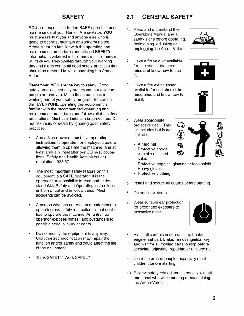
1. Read and understand theOperator’s Manual and allsafety signs before operating,maintaining, adjusting orunplugging the Arena-Vator.
3
2.1 GENERAL SAFETY
2. Have a first-aid kit availablefor use should the needarise and know how to useit.
3. Have a fire extinguisheravailable for use should theneed arise and know how touse it.
4. Wear appropriateprotective gear. Thislist includes but is notlimited to:
- A hard hat- Protective shoes
with slip resistantsoles
- Protective goggles, glasses or face shield- Heavy gloves- Protective clothing
5. Install and secure all guards before starting.
8. Place all controls in neutral, stop tractorengine, set park brake, remove ignition keyand wait for all moving parts to stop beforeservicing, adjusting, repairing or unplugging.
9. Clear the area of people, especially smallchildren, before starting.
10. Review safety related items annually with allpersonnel who will operating or maintainingthe Arena-Vator.
6. Do not allow riders.
7. Wear suitable ear protectionfor prolonged exposure toexcessive noise.
SAFETY
YOU are responsible for the SAFE operation andmaintenance of your Rankin Arena-Vator. YOUmust ensure that you and anyone else who isgoing to operate, maintain or work around theArena-Vator be familiar with the operating andmaintenance procedures and related SAFETYinformation contained in this manual. This manualwill take you step-by-step through your workingday and alerts you to all good safety practices thatshould be adhered to while operating the Arena-Vator.
Remember, YOU are the key to safety. Goodsafety practices not only protect you but also thepeople around you. Make these practices aworking part of your safety program. Be certainthat EVERYONE operating this equipment isfamiliar with the recommended operating andmaintenance procedures and follows all the safetyprecautions. Most accidents can be prevented. Donot risk injury or death by ignoring good safetypractices.
• Arena-Vator owners must give operatinginstructions to operators or employees beforeallowing them to operate the machine, and atleast annually thereafter per OSHA (Occupa-tional Safety and Health Administration)regulation 1928.57.
• The most important safety feature on thisequipment is a SAFE operator. It is theoperator’s responsibility to read and under-stand ALL Safety and Operating instructionsin the manual and to follow these. Mostaccidents can be avoided.
• A person who has not read and understood alloperating and safety instructions is not quali-fied to operate the machine. An untrainedoperator exposes himself and bystanders topossible serious injury or death.
• Do not modify the equipment in any way.Unauthorized modification may impair thefunction and/or safety and could affect the lifeof the equipment.
• Think SAFETY! Work SAFELY!

4
2.2 EQUIPMENT SAFETY GUIDELINES
1. Safety of the operator and bystanders is oneof the main concerns in designing and devel-oping a machine. However, every year manyaccidents occur which could have beenavoided by a few seconds of thought and amore careful approach to handling equipment.You, the operator, can avoid many accidentsby observing the following precautions in thissection. To avoid personal injury or death,study the following precautions and insistthose working with you, or for you, followthem.
2. In order to provide a better view, certainphotographs or illustrations in this manualmay show an assembly with a safety shieldremoved. However, equipment should neverbe operated in this condition. Keep all shieldsin place. If shield removal becomes neces-sary for repairs, replace the shield prior touse.
3. Replace any safety sign or instruction signthat is not readable or is missing. Location ofsuch safety signs is indicated in this manual.
4. Never use alcoholic beverages or drugs whichcan hinder alertness or coordination whileoperating this equipment. Consult your doctorabout operating this machine while takingprescription medications.
5. Under no circumstances should youngchildren be allowed to work with thisequipment. Do not allow persons tooperate or assemble this unit until theyhave read this manual and have developeda thorough understanding of the safetyprecautions and of how it works. Reviewthe safety instructions with all users annually.
6. This equipment is dangerous to children andpersons unfamiliar with its operation. Theoperator should be a responsible, properlytrained and physically able person familiarwith farm machinery and trained in thisequipment's operations. If the elderly areassisting with farm work, their physical limita-tions need to be recognized and accommo-dated.
7. Use a tractor equipped with a Roll OverProtective Structure (ROPS) and a seat belt.
8. Never exceed the limits of a piece of machin-ery. If its ability to do a job, or to do so safely,is in question - DON'T TRY IT.
9. Do not modify the equipment in any way.Unauthorized modification result in seriousinjury or death and may impair the functionand life of the equipment.
10. In addition to the design and configuration ofthis implement, including Safety Signs andSafety Equipment, hazard control and acci-dent prevention are dependent upon theawareness, concern, prudence, and propertraining of personnel involved in the operation,transport, maintenance, and storage of themachine. Refer also to Safety Messages andoperation instruction in each of the appropri-ate sections of the Tractor and machineManuals. Pay close attention to the SafetySigns affixed to the Tractor and the machine.

2.3 SAFETY TRAINING
1. Safety is a primary concern in the design andmanufacture of our products. Unfortunately,our efforts to provide safe equipment can bewiped out by a single careless act of anoperator or bystander.
2. In addition to the design and configuration ofequipment, hazard control and accidentprevention are dependent upon the aware-ness, concern, prudence and proper trainingof personnel involved in the operation, trans-port, maintenance and storage of this equip-ment.
3. It has been said, "The bestsafety feature is an in-formed, careful operator."We ask you to be that kindof an operator. It is theoperator's responsibility to read and under-stand ALL Safety and Operating instructionsin the manual and to follow these. Accidentscan be avoided.
4. Working with unfamiliar equipment can lead tocareless injuries. Read this manual, and themanual for your tractor, before assembly oroperating, to acquaint yourself with themachines. If this machine is used by anyperson other than yourself, or is loaned orrented, it is the machine owner's responsibilityto make certain that the operator, prior tooperating:
a. Reads and understands the operator'smanuals.
b. Is instructed in safe and proper use.
5. Know your controls and how to stop tractor,engine, and machine quickly in an emer-gency. Read this manual and the one pro-vided with your tractor.
6. Train all new personnel and review instruc-tions frequently with existing workers. Becertain only a properly trained and physicallyable person will operate the machinery. Aperson who has not read and understood alloperating and safety instructions is not quali-fied to operate the machine. An untrainedoperator exposes himself and bystanders topossible serious injury or death. If the elderlyare assisting with farm work, their physicallimitations need to be recognized and accom-modated.
2.4 SAFETY SIGNS
1. Keep safety signs clean and legible at alltimes.
2. Replace safety signs that are missing or havebecome illegible.
3. Replaced parts that displayed a safety signshould also display the current sign.
4. Safety signs are available from your author-ized Distributor or Dealer Parts Department orthe factory.
How to Install Safety Signs:
• Be sure that the installation area is clean anddry.
• Be sure temperature is above 50°F (10°C).
• Determine exact position before you removethe backing paper. (See Section 3).
• Remove the smallest portion of the splitbacking paper.
• Align the sign over the specified area andcarefully press the small portion with theexposed sticky backing in place.
• Slowly peel back the remaining paper andcarefully smooth the remaining portion of thesign in place.
• Small air pockets can be pierced with a pinand smoothed out using the piece of signbacking paper.
5
6
2.5 PREPARATION
1. Never operate the tractor and machine untilyou have read and completely understand thismanual, the Tractor Operator's Manual, andeach of the Safety Messages found on thesafety signs on the tractor and machine.
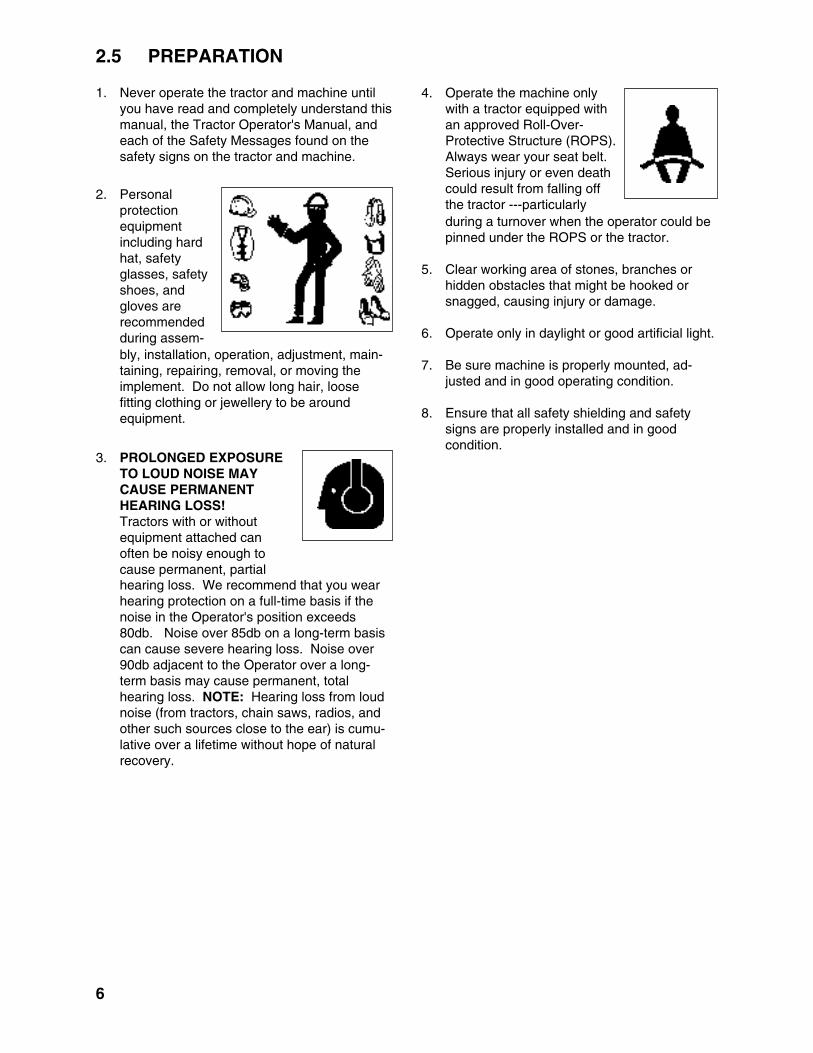
2. Personalprotectionequipmentincluding hardhat, safetyglasses, safetyshoes, andgloves arerecommendedduring assem-bly, installation, operation, adjustment, main-taining, repairing, removal, or moving theimplement. Do not allow long hair, loosefitting clothing or jewellery to be aroundequipment.
3. PROLONGED EXPOSURETO LOUD NOISE MAYCAUSE PERMANENTHEARING LOSS!Tractors with or withoutequipment attached canoften be noisy enough tocause permanent, partialhearing loss. We recommend that you wearhearing protection on a full-time basis if thenoise in the Operator's position exceeds80db. Noise over 85db on a long-term basiscan cause severe hearing loss. Noise over90db adjacent to the Operator over a long-term basis may cause permanent, totalhearing loss. NOTE: Hearing loss from loudnoise (from tractors, chain saws, radios, andother such sources close to the ear) is cumu-lative over a lifetime without hope of naturalrecovery.
4. Operate the machine onlywith a tractor equipped withan approved Roll-Over-Protective Structure (ROPS).Always wear your seat belt.Serious injury or even deathcould result from falling offthe tractor ---particularlyduring a turnover when the operator could bepinned under the ROPS or the tractor.
5. Clear working area of stones, branches orhidden obstacles that might be hooked orsnagged, causing injury or damage.
6. Operate only in daylight or good artificial light.
7. Be sure machine is properly mounted, ad-justed and in good operating condition.
8. Ensure that all safety shielding and safetysigns are properly installed and in goodcondition.

7
2.6 OPERATING SAFETY
1. Please remember it is important that you readand heed the safety signs on the Arena-Vator.Clean or replace all safety signs if they cannotbe clearly read and understood. They arethere for your safety, as well as the safety ofothers. The safe use of this machine is strictlyup to you, the operator.
2. All things with moving parts are potentiallyhazardous. There is no substitute for acautious, safe-minded operator who recog-nizes potential hazards and follows reason-able safety practices. The manufacturer hasdesigned this Arena-Vator to be used with allits safety equipment properly attached, tominimize the chance of accidents. Study thismanual to make sure you have all safetyequipment attached.
3. If a safety shield or guard is removed for anyreason, it must be replaced before the ma-chine is again operated.
4. When the use of hand tools is required toperform any part of assembly, installation,adjustment, maintaining, repairing, removal,or moving, be sure the tools used are de-signed and recommended by the tool manu-facturer for that specific task.
5. Personal protection equipment including hardhat, safety glasses, safety shoes, and glovesare recommended during assembly, installa-tion, operation, adjustment, maintaining,repairing, removal, or moving. Do not allowlong hair, loose fitting clothing, or jewellery tobe around moving parts.
6. Always use two people to handle heavy,unwieldy components during assembly,installation, removal or moving.
7. Never place any part of your body where itwould be in danger if movement should occurduring assembly, installation, operation,maintaining, repairing, removal or moving.
8. Never place yourself between the tractor andmachine while implement is in operation.
9. Do not walk or work under a raised machineor attachment unless it is securely blocked orheld in position. Do not depend on the tractorhydraulic system to hold the machine orattachment in place.
10. A heavy load can cause instability of thetractor. Use extreme care during travel. Slowdown on turns and watch out for bumps. Thetractor may need front counterweights tocounterbalance the weight of the machine.
11. Never use alcoholic beverages or drugs whichcan hinder alertness or coordination whileoperating this equipment. Consult your doctorabout operating this machine while takingprescription medications.
12. Do not allow riders on the machine or tractorat any time. There is no safe place for anyriders.
13. Before you operate the machine, check overall pins, bolts, and connections to be sure allare securely in place. Replace any damagedor worn parts immediately.
14. Do not allow anyone who is not familiar withthe safety rules and operation instructions touse this machine.
15. Never allow children to operate or be aroundthis machine.
16. Use stabilizer bars, adjustable sway chains, orsway blocks on the tractor lift arms to keepthe machine from swinging side to side.Adjust as tightly as practical for best perform-ance.
17. Clear the work area of objects which might bepicked up and snagged or entangled in themachine.
18. Keep hands, feet, hair, jewellery, and clothingaway from all moving and/or rotating parts.

2.7 TRANSPORT SAFETY
8
1. Comply with state and local laws governinghighway safety and movement of farm ma-chinery on public roads.
2. The use of flashing amber lights is acceptablein most localities. However, some localitiesprohibit their use. Local laws should bechecked for all highway lighting and markingrequirements.
3. At all times, when driving the tractor andequipment on the road or highway under 20mph (32 kph) use flashing amber warninglights and a slow moving vehicle (SMV)identification emblem. Do not exceed 20 mph(32 kph). Reduce speed on rough roads andsurfaces.
4. Plan your route to avoid heavy traffic.
5. Always install transport locks, pins or bracketsbefore transporting.
6. Do not drink and drive.
7. Be a safe and courteous driver. Always yieldto oncoming traffic in all situations, includingnarrow bridges, intersections, etc. Watch fortraffic when operating near or crossingroadways.
8. Turn into curves or go up or down hills only ata low speed and at a gradual steering angle.Make certain that at least 20% of the tractor'sweight is on the front wheels to maintain safesteerage. Slow down on rough or unevensurfaces.
9. Never allow riders on either tractor or ma-chine.
2.9 MAINTENANCE SAFETY
1. Good maintenance is your responsibility.Poor maintenance is an invitation to trouble.
2. Follow good shop practices.
- Keep servicearea clean anddry.
- Be sure electricaloutlets and toolsare properlygrounded.
- Use adequatelight for the job athand.
nuts and screws and check that all cotter pinsare properly installed to ensure unit is in asafe condition.
11. When completing a maintenance or servicefunction, make sure all safety shields anddevices are installed before placing unit inservice.
kept readilyaccessible whileperformingmaintenance onthis equipment.
10. Periodicallytighten all bolts,
2.8 STORAGE SAFETY
1. Store the unit in an area away from humanactivity.
2. Do not permit children to play on or aroundthe stored machine.
3. Store the unit in a dry, level area. Support theframe with planks if required.
3. Make sure there is plenty of ventilation.Never operate the engine of the towingvehicle in a closed building. The exhaustfumes may cause asphyxiation.
4. Before working on this machine, shut off theengine, set the brakes, and remove theignition keys.
6. Never work under equipment unless it isblocked securely.
7. Use personal protection devices such as eye,hand and hearing protectors, when performingany service or maintenance work.
8. Where replacement parts are necessary forperiodic maintenance and servicing, genuinefactory replacement parts must be used torestore your equipment to original specifica-tions. The manufacturer will not be responsi-ble for injuries or damages caused by use ofunapproved parts and/or accessories.
9. A fire extinguisher and first aid kit should be

9
EMPLOYEES SIGNATURE EMPLOYERS SIGNATURE
SIGN-OFF FORM
2.10 SIGN-OFF FORM
Manufacturer follows the general Safety Standards specified by the American Society of Agricultural Engi-neers (ASAE) and the Occupational Safety and Health Administration (OSHA). Anyone who will be operat-ing and/or maintaining the Arena-Vator must read and clearly understand ALL Safety, Operating and Mainte-nance information presented in this manual.
Do not operate or allow anyone else to operate this equipment until such information has been reviewed.Annually review this information before the season start-up.
Make these periodic reviews of SAFETY and OPERATION a standard practice for all of your equipment. Wefeel that an untrained operator is unqualified to operate this machine.
A sign-off sheet is provided for your record keeping to show that all personnel who will be working with theequipment have read and understand the information in the Operator’s Manual and have been instructed inthe operation of the equipment.
DATE
10
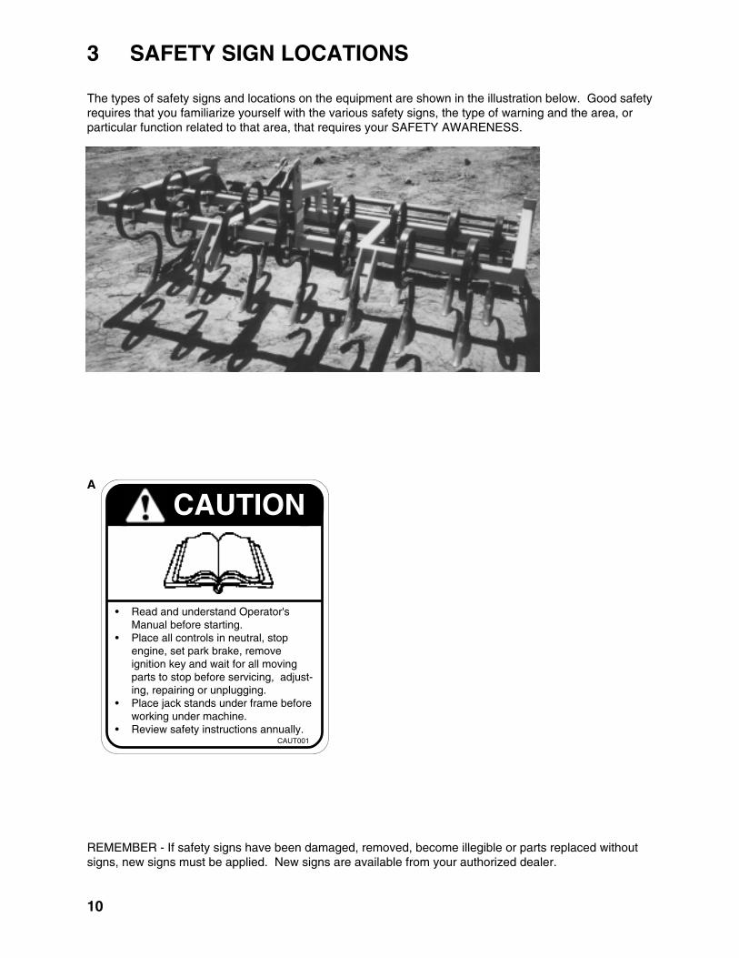
REMEMBER - If safety signs have been damaged, removed, become illegible or parts replaced withoutsigns, new signs must be applied. New signs are available from your authorized dealer.
3 SAFETY SIGN LOCATIONS
The types of safety signs and locations on the equipment are shown in the illustration below. Good safetyrequires that you familiarize yourself with the various safety signs, the type of warning and the area, orparticular function related to that area, that requires your SAFETY AWARENESS.
A
A
CAUTION
• Read and understand Operator'sManual before starting.
• Place all controls in neutral, stopengine, set park brake, removeignition key and wait for all movingparts to stop before servicing, adjust-ing, repairing or unplugging.
• Place jack stands under frame beforeworking under machine.
• Review safety instructions annually.CAUT001

11
OPERATING SAFETY1. Read and understand the Operator’s
Manual and all safety signs before operat-ing, servicing, adjusting, repairing or un-plugging.
2. Do not allow riders.
3. Install and secure all guards and shieldsbefore starting or operating.
4. Keep hands, feet, hair and clothing awayfrom moving parts.
5. Place all controls in neutral, stop tractorengine, set park brake, remove ignition keyand wait for all moving parts to stop beforeservicing, adjusting, repairing or unplugging.
6. Place all tractor and machine controls inneutral before starting.
7. Never start or operate machine unlesssitting on tractor seat.
8. Clear the area of bystanders, especiallysmall children, before starting.
9. Clean reflectors, SMV and lights beforetransporting.
10. Use hazard flashers on tractor when trans-porting.
11. Do not put hands or feet under machinewhile tractor engine is running.
12. Review safety instructions with all operatorsannually.
4.1 TO THE NEW OPERATOR OR OWNER
The Arena-Vator is designed as a light duty tillagetool for working up, leveling, packing andconditioning the soil and surface. Be familiar withthe machine before starting.
It is the responsibility of the owner or operatorto read this manual and to train all otheroperators before they start working with themachine. Follow all safety instructions ex-actly. Safety is everyone's business. Byfollowing recommended procedures, a safeworking environment is provided for theoperator, bystanders and the area around theworksite. Untrained operators are not quali-fied to operate the machine.
Many features incorporated into this machine arethe result of suggestions made by customers likeyou. Read this manual carefully to learn how tooperate the machine safely and how to set it toprovide maximum field efficiency. By following theoperating instructions in conjunction with a goodmaintenance program, your Arena-Vator willprovide many years of trouble-free service.
4 OPERATION

12
4.2 MACHINE COMPONENTS
The Arena-Vator consists of acultivator assembly up front, aleveling blade and a rear roller. Itwill work the soil, level it, packand condition the surface in onepass.
Fig. 1 MACHINE COMPONENTS
4.3 MACHINE BREAK-IN
Although there are no operational restrictions onthe Arena-Vator when used for the first time, it isrecommended that the following mechanical itemsbe checked:
A. After Operating For 1 and 5 Hours:
1. Check all nuts, bolts and other fasteners.Tighten to their specified torque level.
2. Check that the tines are in good condition.
3. Then go to the regular service scheduleas defined in Section 5.
4.4 PRE-OPERATION CHECKLIST
Efficient and safe operation of the Arena-Vatorrequires that each operator reads and under-stands the operating procedures and all relatedsafety precautions outlined in this section. A pre-operation checklist is provided for the operator. Itis important for both the personal safety andmaintaining the good mechanical condition of theArena-Vator that this checklist is followed.
Before operating the machine and each timethereafter, the following areas should be checkedoff:
1. Use only a small Agricultural tractor of therecommended horsepower on the machine.
2. Check that the machine is properly attachedto the tractor. Be sure retainers are used onthe mounting pins.
3. Be sure extra weights are mounted on thefront of the tractor if required.
4. Check the tines/shovels/blade/roller. Be surethey are not damaged or broken and is notbadly worn. Repair or replace as required.
5. Check for entangled material. Remove thismaterial.
A Mounting FrameB Cultivator FrameC Reversible Points/ShovelsD TinesE Leveling BladeF RollerG Floating Top Link Bracket
E
FC
C
D D
B
AG

13
4.5 FIELD OPERATION
The Arena-Vators are designed as a light dutytillage tool used to work up horse arenas andtracks, level them and pack/condition the surface.However the operator has the responsibility ofbeing familiar with all operating and safety proce-dures and following them.
Each operator should review this section of themanual at the start of the season and as often asrequired to be familiar with the machine. Whenusing, follow this procedure:
OPERATING SAFETY1. Read and understand the Operator’s Manual
and all safety signs before operating, servic-ing, adjusting, repairing or unplugging.
2. Do not allow riders.
3. Install and secure all guards and shieldsbefore starting or operating.
4. Keep hands, feet, hair and clothing awayfrom moving parts.
5. Place all controls in neutral, stop tractorengine, set park brake, remove ignition keyand wait for all moving parts to stop beforeservicing, adjusting, repairing or unplugging.
6. Place all tractor and machine controls inneutral before starting.
7. Never start or operate machine unless sittingon tractor seat.
8. Clear the area of bystanders, especiallysmall children, before starting.
9. Clean reflectors, SMV and lights beforetransporting.
10. Use hazard flashers on tractor when trans-porting.
11. Do not put hands or feet under machinewhile tractor engine is running.
12. Review safety instructions with all operatorsannually.
Fig. 2 ATTACHED
1. Review and follow the Pre-Opera-tion Checklist.
2. Attach the tractor to the machine.
a. Move the lift arms and slidethe balls over the mountingpins. Install the retainers.
b. Attach the top link to the mastbracket. Install the retainer.
IMPORTANT
Do not use on a tractor of morethan the recommended horse-power. Larger tractors canoverload and bend the frame ortines, blades and the roller.
c. Always engage the anti-swaycomponents on each lift armto keep the unit from movingfrom side-to-side duringoperation.

14
Fig. 3 LEVELING
3. Horsepower/3 Point Hitch:Each Arena-Vator model is designed tobe used on a tractor of a certain horse-power range and 3 point hitch size asspecified in Table 1. Do not exceed therecommended horsepower range toprevent overloading the structuralcomponents. Always use the appropri-ately sized mounting pins when hookingup to a tractor.
4. Before going to the working area reviewSection 4.6 Transporting.
5. Drive to the working area and stop in alevel area.
6. Position the machine about 2" abovethe ground. Be sure the roller is off theground.
7. Set the Machine:
MODEL SHANKS HITCH HORSEPOWERCATEGORY RANGE
AV-5 13 CAT 1 18-32
AV-6 15 CAT 1 22-39
AV-7 19 CAT 1 & 2 30-53
TABLE 1 HORSEPOWER VS MODEL
a. Level the Frame:Use the screw jack onthe right lift arm to levelthe frame from side-to-side.
b. Frame Angle:Use the turnbuckle onthe top link to set theframe angle. Start byusing the top link to setthe frame level with theground. Then, extendthe top link by turningthe turnbuckle anotherfull turn. This will lowerthe roller and allow theframe to follow thecontours of the groundthrough the movablemast bracket duringoperation.
ab
c. 3 Point Hitch:Set the 3 point hitch on the tractor into the"float" mode to allow the frame/machine tofollow the contour of the ground. This willallow all components to work the soilevenly.

15
Fig. 4 BLADE/ROLLER
Blade Depth
Blade Angle
Working
d. Beveled Blade Position:The beveled blade islocated directly behind thecultivator section and isused to spread and levelthe soil loosened by thecultivator.
A good starting positionwould be in the secondhole on the strap. This willplace the blade slightlyabove the cultivator shoveldepth position. Lower if theblade is not distributing ormoving the soil along thewidth of the cut. Raise if alot of soil is going over thetop of the blade. Set bothends of the blade in thesame hole.
e. Beveled Blade Angle:The bevel blade mountingframe is designed with aslotted mounting hole toprovide a way to adjust theblade angle. To set theangle, loosen mounting boltand tap blade into thedesired position. Tightenmounting bolt to its speci-fied torque. Set both endsof the blade at the sameangle.
f. Mulcher Roller:The mulcher roller isdesigned with an adjust-able mounting frame toallow the operator to setthe depth of the rollerduring operation. The bestresults are obtained whenthe roller is set slightlyhigher than the depth of thecultivator shovels. Itshould pack, condition andcompress the soil as themachine moves across theworking area.
Observe the quality of thejob when starting to work.Raise the roller if thecultivator is not able topenetrate the surface andwork up the soil. Lower ifthe soil is not being com-pressed.
e
e
d
g
f d
e

Fig. 6 DEPTH
16
8. Drive over the area to beleveled.
9. Ground Speed:Although the Arena-Vatorcan be operated at anyspeed, it is recommendedthat slow speeds be used.High speeds can lead toskipping by the tines and anuneven job. Two to four mphwill give the best results. Theoperator will have to experi-ment a little to determine thebest speed. Use the type ofjob being done as a guide.
Fig. 5 FIELD
10. Depth:The machine is designed asa light to medium duty tillagetool for working up, leveling,conditioning and compactingarenas and tracks. The bestresults are obtained whenthe cultivator works up thesoil 2 to 5 inches deep. Asthe blade smooths andlevels the worked up soil, itis distributed across theworking area. The mulcherroller can then condition andcompact the soil.
Lower the blade and roller toraise the cultivator if the soilis soft and large amounts ofsoil goes over the blade.Raise the blade if the soil ishard and the shovels/tinesneed to work up the soilmore.

11. Operating Hints:
a. Use the weight ofthe machine topush the tines intothe ground. Addno more than 100lbs. to the framewhen the ground ishard or deeplyrutted. Do not addmore weight andpush the tines toofar into the groundand damage theframe.
b. Use the amount ofsoil ahead of theblade as a guide tohow the machine isfunctioning. Thereshould always be anominal amount ofsoil coming over
17
Fig. 7 WORKING
the blade. This will insure that the soil ismoved across the width of the machine.
c. In severely compacted or deeply ruttedconditions, it is recommended that morethan one pass be made to level, conditionand compact the soil.

18
4.6 TRANSPORTING
TRANSPORT SAFETY
4.7 STORAGE
1. Make sure you are in compliance with alllocal regulations regarding transportingequipment on public roads and highways.
2. Make sure the SMV (Slow Moving Vehicle)emblem and all the lights and reflectors thatare required by the local highway andtransport authorities are in place, are cleanand can be seen clearly by all overtakingand oncoming traffic.
3. Do not allow anyone to ride on the Arena-Vator or tractor during transport.
4. Do not exceed 20 mph (32 kph). Reducespeed on rough roads and surfaces.
5. Use retainers on the mounting pins whenattaching.
6. Always use hazard flashers on the tractorwhen transporting unless prohibited by law.
1. Store the unit in an area away from humanactivity.
2. Do not permit children to play on or aroundthe stored machine.
3. Store the unit in a dry, level area. Supportthe frame with planks if required.
STORAGE SAFETY
When transporting the machine, review and followthese instructions:
1. Be sure all bystanders are clear of the machine.
2. Be sure that the machine is securely attachedto the tractor and all retainer pins are installed.
3. Be sure you have installed extra weights on thefront of the tractor if required.
4. Clean the SMV emblem, lights and reflectorsand be sure they are working.
5. Be sure you are in compliance with all appli-cable lighting and marking regulations whentransporting. Check with your local authorities.
6. Be sure your machine can clearly be seen byovertaking and oncoming traffic.
7. Keep to the right and yield the right-of-way toallow faster traffic to pass. Drive on the roadshoulder if permitted by law.
8. Do not allow riders.
9. Always use hazard flashers on the tractor whentransporting unless prohibited by law.
After the season's use, the machine should bethoroughly inspected and prepared for storage.Repair or replace any worn or damaged compo-nents to prevent any unnecessary down time atthe start of next season. To insure a long, troublefree life, this procedure should be followed whenpreparing the unit for storage:
1. Clear the area of bystanders, especially smallchildren.
2. Thoroughly wash the machine using a pres-sure washer to remove all dirt, mud, debrisand residue.
3. Inspect the tines and pivot for damage orentangled material. Repair or replace dam-aged parts. Remove all entangled material.
4. Touch up all paint nicks and scratches toprevent rusting.
5. Move to storage area.
6. Select an area that is dry, level and free ofdebris.
7. Unhook from tractor.
8. If the machine cannot be placed inside, coverwith a waterproof tarpaulin and tie securely inplace.
9. Store the machine in an area away fromhuman activity.
10. Do not allow children to play on or around thestored machine.

19
5 SERVICE AND MAINTENANCE
1. Follow ALL the operating, maintenance andsafety information in the manual.
2. Support the machine with blocks or safetystands when working beneath it.
3. Follow good shop practices.
- Keep service area clean and dry.- Be sure electrical outlets and tools are
properly grounded.- Use adequate light for the job at hand.
3. Make sure there is plenty of ventilation. Neveroperate the engine of the towing vehicle in aclosed building. The exhaust fumes may causeasphyxiation.
4. Use only tools, jacks and hoists of sufficientcapacity for the job.
5. Make sure all guards are in place and properlysecured when maintenance work is completed.
6. Keep hands, feet, hair and clothing away frommoving or rotating parts.
7. Clear the area of bystanders, especially smallchildren, when carrying out any maintenanceand repairs or making any adjustments.
MAINTENANCE SAFETY 5.1 SERVICE
5.1.1 FLUIDS AND LUBRICANTS
1. Grease:Use an SAE multi-purpose high temperaturegrease with extreme pressure (EP) perform-ance. Also acceptable is an SAE multipur-pose lithium base grease.
2. Storing Lubricants:Your machine can operate at top efficiencyonly if clean lubricants are used. Use cleancontainers to handle all lubricants. Storethem in an area protected from dust, mois-ture and other contaminants.
5.1.2 GREASING
Use the Maintenance Checklist provided tokeep a record of all scheduled maintenance.
1. Use a hand-held grease gun for all greas-ing.
2. Wipe grease fitting with a clean clothbefore greasing to avoid injecting dirt andgrit.
3. Replace and repair broken fittings immedi-ately.
4. If fittings will not take grease, remove andclean thoroughly. Also clean lubricantpassage. Replace fitting if necessary.

20
5.1.4 SERVICE RECORD
See Lubrication and Maintenance sections for details of service. Copy this page to continue record.
ACTION CODE: G GREASE CL CLEAN
HOURS
SERVICED BY
MAINTENANCE
G Roller Bearings (2)
Daily or 10 Hours
CL Machine
Annually
5.1.3 SERVICING INTERVALS
The period recommended is based on normaloperating conditions. Severe or unusual condi-tions may require more frequent servicing.
Daily or 10 Hours
1. Grease rollerbearings ( 2 loca-tions).
Fig. 8 ROLLER BEARINGS
Annually
1. Clean machine.

21
6 TROUBLE SHOOTING
The Arena-Vator consists of a cultivator, blade and roller to work up, level and condition soil. It is a simpleand reliable system that requires minimal maintenance.
In the following section, we have listed many of the problems, causes and solutions to the problems thatyou may encounter.
If you encounter a problem that is difficult to solve, even after having read through this trouble shootingsection, please call your dealer or distributor. Before you call, please have this Operator's Manual and theserial number from your Arena-Vator ready.
PROBLEM CAUSE SOLUTION
Soil isn't being worked up. Compacted soil. Raise blade and roller toplace more weight oncultivator.
Add weight to cultivatorframe. Do not exceed 100 lbs.
Make 2 passes.
Tines skip over ground. Driving too fast. Slow down.
Set hitch in "float" mode.
Shovels wore out. Replace shovels.
Machine skips over the ground. Compacted soil. Slow down.
Add weight to frame.
Slow down and make 2passes.
Ruts aren't being filled. Blade too high. Lower blade.
Compacted soil. Add weight to frame and makeseveral passes.

7 ASSEMBLY
22
The machine is shipped from the factory in apartially disassembled form that allows for easyand convenient shipping.
When preparing for the customer, follow thisprocedure:
1. Clear the area of bystanders, especiallysmall children.
2. Use 2 men to guide or direct and handle theheavy and bulky components.
3. Use a crane, hoist or forklift of sufficientcapacity and stability to handle the compo-nents.
4. Attach to the lifting device, remove tie-downs, lift from the truck and move to theassembly area. Drive slow and keep themachine close to the ground.
5. Cut the strapping and remove the compo-nents from the shipping pallet.
6. Mount the reversible points or shovels tothe tines and tighten fasteners to theirspecified torque.
Fig. 10 TINES WITH REVERSIBLE POINTS/SHOVELS
Fig. 9 SHIPPING CONFIGURATION
Fig. 11 LAY-OUT
7. Place the cultivatorframe on stands andlay-out the compo-nents in their approxi-mate position.
23
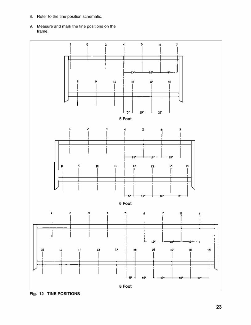
Fig. 12 TINE POSITIONS
5 Foot
8 Foot
8. Refer to the tine position schematic.
9. Measure and mark the tine positions on theframe.
6 Foot

24
Fig. 13 3 POINT HITCH MOUNTS
10. Install the 3 pointhitch mounting pins intheir brackets.
11. Install the floating toplink bracket to the topof the 3 point hitch.Do not clamp andovertighten. Bracketmust be free to moveduring operation.
Fig. 14 TINES
Front
All
12. Mount the tines to frame andtighten fasteners to their speci-fied torque.

25
Fig. 15 BLADE
Arm
Height Bracket
13. Attach the blade:
a. Mount the blade and arm tothe center of the frame.
NOTE
Start with the height bracket in its2nd hole position.
b. Mount the height bracketto the arm and the frame.

26
14. Attach the roller to the rearframe.
Fig. 16 ROLLER
Left
Right
Fig. 17 ASSEMBLED
15. Tighten allfasteners totheirspecifiedtorque.

8 SPECIFICATIONS
8.1 MECHANICAL
27
MODELS AV-5 AV-6 AV-8
WORKING WIDTH 5' 6' 8'
NUMBER OF SHANKS 13 15 19
SHANK SIZE 1 1/4" X 1/2" X 22" 1 1/4" X 1/2" X 22" 1 1/4" X 1/2" X 22"
SHANK CLEARANCE 17" 17" 17"
HITCH CAT. 1 CAT. 1 CAT. 1 & 2
HP RATING 18 TO 32 22 TO 39 30 TO 53
WEIGHT 500 575 775
LEVELING BAR 1/2" X 6" 1/2" X 6" 1/2" X 6"
DOUBLE BEVELED DOUBLE BEVELED DOUBLE BEVELED
BoltDiameter"A"
1/4"5/16"3/8"
7/16"1/2"
9/16"5/8"3/4"7/8"1"
(6)(10)(20)(30)(45)(70)(95)(165)(170)(225)
SAE 2N.m (lb-ft)
SAE 5N.m (lb-ft)
SAE 8N.m (lb-ft)
81327416195128225230345
12254572110155215390570850
(9)(19)(33)(53)(80)(115)(160)(290)(420)(630)
1736631001552203055408801320
(12)(27)(45)(75)(115)(165)(220)(400)(650)(970)
Bolt Torque *
CHECKING BOLT TORQUE
The tables shown below give correct torque values for various bolts and capscrews. Tighten all bolts tothe torques specified in chart unless otherwise noted. Check tightness of bolts periodically, using bolttorque chart as a guide. Replace hardware with the same strength bolt.
ENGLISH TORQUE SPECIFICATIONS
8.2 BOLT TORQUE
SPECIFICATIONS ARE SUBJECT TO CHANGE WITHOUT NOTICE
Torque figures indicated above are valid for non-greased or non-oiled threads and heads unless other-wise specified. Therefore, do not grease or oil bolts or capscrews unless otherwise specified in thismanual. When using locking elements, increase torque values by 5%.
* Torque value for bolts and capscrews are identified by their head markings.

9 INDEX
28
PAGES
Safety ............................................................. 2 Equipment Safety Guidelines .................... 4 General Safety .......................................... 3 Maintenance Safety ................................... 8 Operating Safety ....................................... 7 Preparation ................................................ 6 Safety Training .......................................... 5 Safety Signs .............................................. 5 Sign-Off Form ............................................ 9 Storage Safety ........................................... 8 Transport Safety ........................................ 8Safety Sign Locations ................................... 10Service and Maintenance ............................. 19 Service .................................................... 19 Fluid and Lubricants ............................. 19 Greasing ............................................... 19 Service Record ..................................... 20 Servicing Intervals ................................ 20Specifications ............................................... 27 Bolt Torque .............................................. 27 Mechanical .............................................. 27
PAGEA
Assembly ...................................................... 22
Introduction .................................................... 1
I
O
Operation ..................................................... 11 Field Operation ........................................ 13 Machine Break-In .................................... 12 Machine Components ............................. 12 Pre-Operation Checklist .......................... 12 Storage .................................................... 18 To the New Operator or Owner ............... 11 Transporting ............................................ 18
T
Trouble Shooting .......................................... 21

.

.PRINTED IN USAISSUE DATE: JULY, 2003 PART NUMBER: OMAV001
RANKIN EQUIPMENT CO.P.O. BOX 168YAKIMA, WA98907-0168
PHONE (509) 453-8271FAX (509) 457-2456


