26
ArKaos LED Mapper for ArKaos MediaMaster Documentation
ArKaos LED Mapper for ArKaos MediaMaster
Documentation

Table of content
Table of content................................................................1
Introduction.......................................................................31. Concepts............................................................................................4
2. Hardware setup..................................................................................52.1. ArtNet, Nodes and Switches...................................................................52.2. e:cue butlers............................................................................................62.3. Computer.................................................................................................6
3. Installation..........................................................................................7
4. LED Mapper presentation.................................................................8
5. Fixture library.....................................................................................95.1. Creating or modifying a LED Fixture ....................................................105.2. Exchanging the LED Fixture library .....................................................11
6. Creating the mapping......................................................................126.1. Creating the elements...........................................................................126.2. Editing the element...............................................................................136.3. Deleting an element..............................................................................146.4. Duplicating an element..........................................................................14
7. Mapping resolution..........................................................................16
8. Project files......................................................................................18
9. Enabling LED Output in ArKaos MediaMaster..............................19
Support, Information and Contact................................201. Solutions..........................................................................................20
1.1. ArKaos Users Forum.............................................................................201.2. Knowledgebase articles........................................................................201.3. Trouble Ticket System..........................................................................20
2. Distributors and resellers...............................................................20

ArKaos LED Mapper documentation Page 2 / 26
IntroductionLED lighting has become very relevant for live entertainment and TV over the last few years. The LED Mapper for ArKaos MediaMaster is the answer to the market’s request for an intuitive and flexible software solution to drive these LED panels or any lighting fixture from a media server.
Thanks to LED output, you can map the media server video output directly to LED devices using ArtNet (DMX over Ethernet protocol, which can easily be converted into a standard DMX signal using Ethernet-DMX nodes) or through e:cue butler devices.
From a single ArKaos MediaMaster Server, it is possible to control as many LED fixtures as you want (within the limit of 256 DMX universes)
Since LED panel resolution is fairly small, a setup usually consists in quite a bit of panels, possibly with different characteristics and following a very specific layout. To create and edit the mapping of the video output to the panels, we provide an external application called the LED Mapper that allows you to manipulate both the spatial arrangement and DMX definitions of all the LED devices involved. After designing the setup in this application, it saves a “mapping file” that is read by ArKaos MediaMaster who sends its output to the LED displays based on your definition.
This document will give all details about the LED Mapper and the LED Output in ArKaos MediaMaster. For a short introduction and first hands on, you can also check the Quick Start PDF installed with the LED Mapper application.
Note on LicensingIn order to use the ArKaos LED Mapper, you will need to first register ArKaos MediaMaster.
1. Concepts
The LED output in ArKaos MediaMaster aims at driving LED fixtures through DMX addressing. Since there’s a lot of different panels vendors, LED fixtures have very different properties when it comes to resolution, pixel type, channel mapping, etc...
Our software has been designed to handle any type of fixture as long as they are driven through DMX.
To drive the fixtures, ArKaos uses the ArtNet protocol (DMX over Ethernet) or e:cue butlers. If some of your panels don’t directly support ArtNet, it can be easily converted into a classic DMX signal using so-called Ethernet nodes. ArtNet gives provision for up to 256 DMX universes, allowing the handling of a lot of elements. e:cue butlers come with two DMX outputs by default, therefore you don’t need additional hardware. The principle of the LED Mapper is very simple: Using the LED Mapper application, you describe which area of the video output will be sent to each LED devices along with their DMX addressing (universe and base channel). Once the configuration for a particular show has been defined, it is saved in a ‘mapping’ file that will be read by ArKaos MediaMaster to push the right pixels to the right LED Panels.
During the show, ArKaos MediaMaster is controlled in the usual way. The video output can still be used to control video projectors but pixel information will also be sent over ArtNet or e:cue butlers according to the definition created in the LED Mapper application.
2. Hardware setup
This part will give you an idea of the various hardware elements used to drive LED fixtures from ArKaos MediaMaster.
2.1. ArtNet, Nodes and Switches
As explained in the previous part, the ArKaos LED output aims at driving LED fixtures with a DMX input. ArKaos MediaMaster will always send DMX information over ArtNet on a single Ethernet adapter that, depending on the type of fixture, might need to be converted into a DMX signal with Ethernet nodes.
Most Ethernet nodes are ArtNet compatible, and a lot of them are dedicated to ArtNet protocol. The ArtNet protocol can transfer up to 256 DMX universes, allowing to control up to 131.072 DMX channels. DMX universes in ArtNet are specified by means of two parameters: subnet and universe: there are 16 subnet and 16 universes (both ranging from 0 to 15). On each Ethernet nodes, you must select which subnet / universe they will be listening to transfer the signal onto their DMX output.
If you need to access more than 1 DMX universe, you will either need more nodes or use nodes that can cope more than one output/universe, providing several regular DMX outputs.
If you use multiple nodes, you will need network switches to connect the single ArtNet output from ArKaos MediaMaster to the various nodes. If you have to control a lot of universes, it is important to use a professional grade network switches to ensure a smooth transfer of the information.
Here is a schematic of a typical installation:
2.2. e:cue butlers
An installation with e:cue butlers will be similar as the one presented above; the computer is linked to an Ethernet switch with e:cue butlers connected. Each butler has two DMX outputs that can be connected to your devices.
2.3. Computer
The necessary computer setup varies depending on the size of the installation and the number of Panels involved. If you drive only a few panels and don’t use the video output, a small computer or a laptop will be more than enough. However, in a setup with a lot of fixtures, you will need a powerful machine and a 1 GB/s network can improve performances a lot. Remember that all the pixel information has to be sent on the network so its performance is as important as the computer’s.
For reference, we’ve done a few tests in house, driving 120 DMX universes using a P4 2.8 GHz and a 100Mb/s network and ArKaos MediaMaster was still running at a satisfying 30 FPS (frames per second).
3. Installation
To load the LED Mapper Project (.LMP file) in MediaMaster, open Preferences (menu Edit / Preferences) and select the “LED Output” tab. There you have to check the “Activate” checkbox and use the button below to select the LMP file you want to use.
To install you setup, you will need to go through the following steps:
Install ArKaos MediaMaster
Register the application. For more information about MediaMaster registration, please refer to MediaMaster documentation.
Install the ArKaos LED Mapper application.
4. LED Mapper presentation
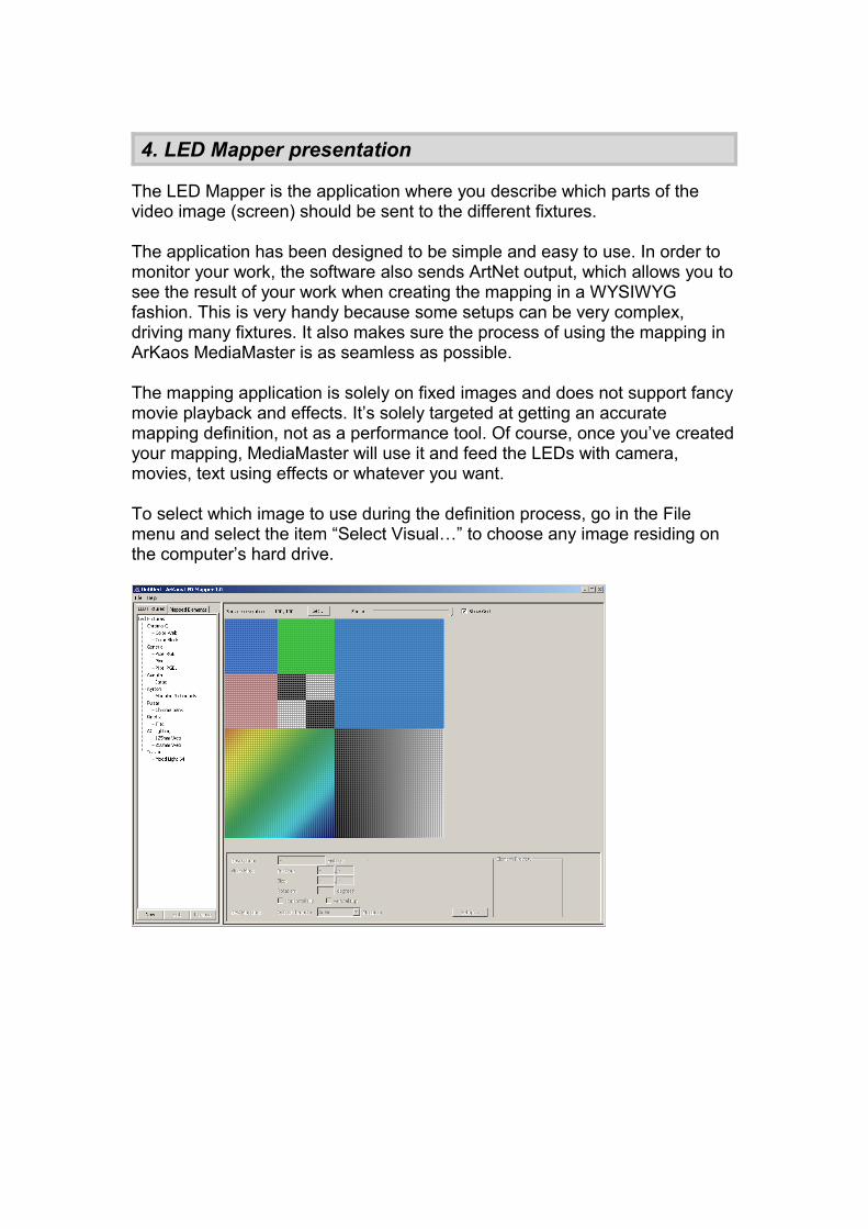
The LED Mapper is the application where you describe which parts of the video image (screen) should be sent to the different fixtures.
The application has been designed to be simple and easy to use. In order to monitor your work, the software also sends ArtNet output, which allows you to see the result of your work when creating the mapping in a WYSIWYG fashion. This is very handy because some setups can be very complex, driving many fixtures. It also makes sure the process of using the mapping in ArKaos MediaMaster is as seamless as possible.
The mapping application is solely on fixed images and does not support fancy movie playback and effects. It’s solely targeted at getting an accurate mapping definition, not as a performance tool. Of course, once you’ve created your mapping, MediaMaster will use it and feed the LEDs with camera, movies, text using effects or whatever you want.
To select which image to use during the definition process, go in the File menu and select the item “Select Visual…” to choose any image residing on the computer’s hard drive.
5. Fixture library
The mapping software is based on the concept of using a fixture library. This library contains the definition for various Fixtures, storing their intrinsic parameters such as the number of pixels they cover, the channel offset for each of pixel and so on.
Once you have defined the library elements, you are free to use them as many times as you wish in a given mapping setup. Each fixture element used for a particular configuration becomes a ‘mapping element’ that you can arrange interactively, specifying for each of them the universe and start channel to be used.
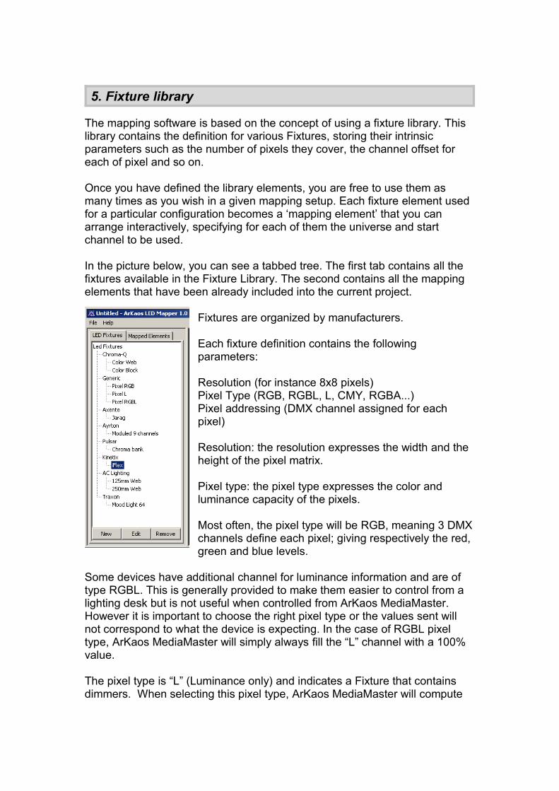
In the picture below, you can see a tabbed tree. The first tab contains all the fixtures available in the Fixture Library. The second contains all the mapping elements that have been already included into the current project.
Fixtures are organized by manufacturers.
Each fixture definition contains the following parameters:
Resolution (for instance 8x8 pixels)Pixel Type (RGB, RGBL, L, CMY, RGBA...)Pixel addressing (DMX channel assigned for each pixel)
Resolution: the resolution expresses the width and the height of the pixel matrix.
Pixel type: the pixel type expresses the color and luminance capacity of the pixels.
Most often, the pixel type will be RGB, meaning 3 DMX channels define each pixel; giving respectively the red, green and blue levels.
Some devices have additional channel for luminance information and are of type RGBL. This is generally provided to make them easier to control from a lighting desk but is not useful when controlled from ArKaos MediaMaster. However it is important to choose the right pixel type or the values sent will not correspond to what the device is expecting. In the case of RGBL pixel type, ArKaos MediaMaster will simply always fill the “L” channel with a 100% value.
The pixel type is “L” (Luminance only) and indicates a Fixture that contains dimmers. When selecting this pixel type, ArKaos MediaMaster will compute
each of the pixel’s luminosity and send it to the fixture. In this case each pixel uses only one DMX channel.
The CMY pixel type can be used to map moving light with CMY channels. Note that for controlling moving light with LED Mapper, you would need an “ArtNet merger” and some programming.
Pixel addressing:In order to drive each pixel inside the matrix, we need to define the channel offset of each pixel inside the fixture. Many fixtures maps pixels from left to right and from top to bottom, but this is not always the case. In order to cope with all situations, the software allows pixels to be addressed freely or using an auto-map feature covering most of the cases.
5.1. Creating or modifying a LED Fixture
To edit an existing fixture, just select it in the fixture library tree and press the “Edit” button at the bottom of the list. Alternatively, you can also double-click the fixture.
To create a new feature, press the “New” button below the fixture list.
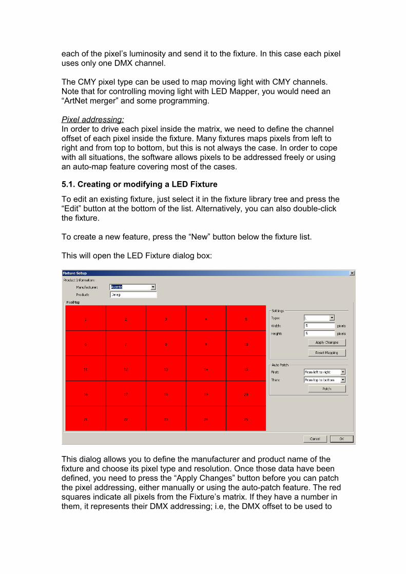
This will open the LED Fixture dialog box:
This dialog allows you to define the manufacturer and product name of the fixture and choose its pixel type and resolution. Once those data have been defined, you need to press the “Apply Changes” button before you can patch the pixel addressing, either manually or using the auto-patch feature. The red squares indicate all pixels from the Fixture’s matrix. If they have a number in them, it represents their DMX addressing; i.e, the DMX offset to be used to
address that particular pixel. Pixels without numbers are not addressed, no pixel information will be sent to them
Auto-patching gives a simple way to define an addressing that follows a row/column pattern. Simply specify the rule to fill out the matrix and click ‘patch’. You will see the resulting addressing displayed inside the pixels.
To Patch pixels address manually, you need to click red square one at a time in the correct order. Each time you click an unpatched pixel, it will be given the next available DMX channel. You can always use the “Reset” button to clear completely the mapping.
5.2. Exchanging the LED Fixture library
The fixture library is saved in a file called “LEDFixtureLib.lml” residing in the LED Mapper application folder. To share the library you created with someone else, or just to transfer your library from one computer to another, you can copy this file to the other computer (making sure you don’t replace the original file on that installation) and import it in the application using the “Import Fixtures…” menu entry from the file menu. This action will allow you to merge the two library files. If some fixtures are already in the library a confirmation dialog will ask you if you want to overwrite the fixture in your library or if you want to skip this particular fixture and continue.
6. Creating the mapping
6.1. Creating the elements
When your set of fixtures is ready, you can start building a specific mapping, which can combine several fixtures into a mapping. To add a fixture, simply drag & drop it from the library onto the mapping area located on the right side of the screen. It will automatically create a ‘mapping element’ (an instance of a fixture in the mapping) and open the DMX patch window.
If you use ArtNet, the Patch window will let you set the ArtNet subnet / universe and start channel for that particular element. If you want to patch the element to an e:cue butler output, you can select it in the element details area at the bottom of the screen. Once you patched one device, the next ones will use the same output type by default, but you are free to change it and mix ArtNet and e:cue butler outputs.
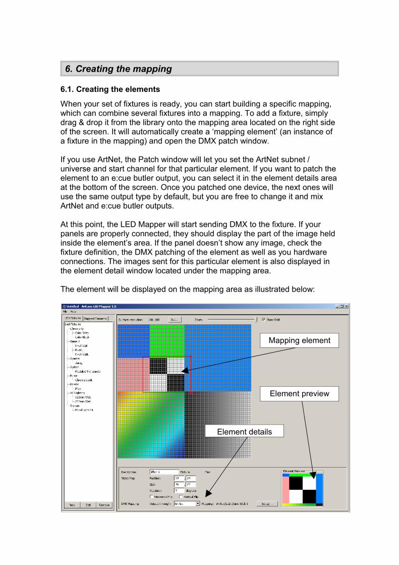
At this point, the LED Mapper will start sending DMX to the fixture. If your panels are properly connected, they should display the part of the image held inside the element’s area. If the panel doesn’t show any image, check the fixture definition, the DMX patching of the element as well as you hardware connections. The images sent for this particular element is also displayed in the element detail window located under the mapping area.
The element will be displayed on the mapping area as illustrated below:
Element preview
Mapping element
Element details
6.2. Editing the element
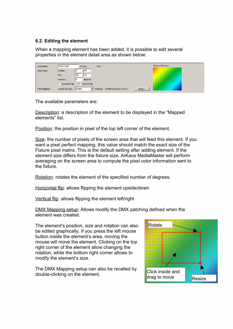
When a mapping element has been added, it is possible to edit several properties in the element detail area as shown below:
The available parameters are:
Description: a description of the element to be displayed in the “Mapped elements” list.
Position: the position in pixel of the top left corner of the element.
Size: the number of pixels of the screen area that will feed this element. If you want a pixel perfect mapping, this value should match the exact size of the Fixture pixel matrix. This is the default setting after adding element. If the element size differs from the fixture size, ArKaos MediaMaster will perform averaging on the screen area to compute the pixel color information sent to the fixture.
Rotation: rotates the element of the specified number of degrees.
Horizontal flip: allows flipping the element upside/down
Vertical flip: allows flipping the element left/right
DMX Mapping setup: Allows modify the DMX patching defined when the element was created.
The element’s position, size and rotation can also be edited graphically. If you press the left mouse button inside the element’s area, moving the mouse will move the element. Clicking on the top right corner of the element allow changing the rotation, while the bottom right corner allows to modify the element’s size.
The DMX Mapping setup can also be recalled by double-clicking on the element. Click inside and
drag to move
Rotate
Resize
6.3. Deleting an element
To delete an element, simply select it and press the “Delete” key, a dialog will show up to confirm the deletion. Alternatively, you can right click on the element, and select the “Remove” entry in the contextual menu or select the element in the mapping element list on the left side of the application and press the “Remove” button below the list.
6.4. Duplicating an element
To earn time when creating a big setup with many similar fixtures (for instance 16x10 = 160 fixtures), it is possible to duplicate elements. To duplicate an element, right click on it and select “Duplicate…” from the contextual menu.
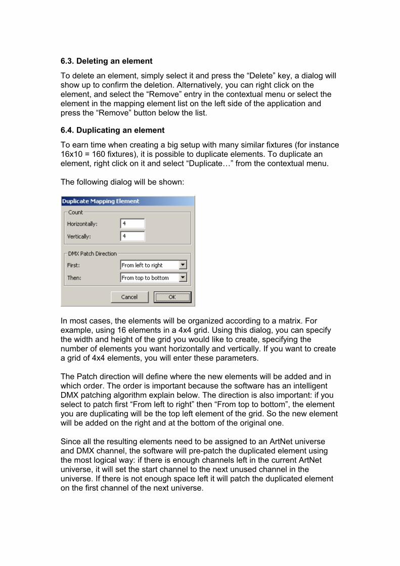
The following dialog will be shown:
In most cases, the elements will be organized according to a matrix. For example, using 16 elements in a 4x4 grid. Using this dialog, you can specify the width and height of the grid you would like to create, specifying the number of elements you want horizontally and vertically. If you want to create a grid of 4x4 elements, you will enter these parameters.
The Patch direction will define where the new elements will be added and in which order. The order is important because the software has an intelligent DMX patching algorithm explain below. The direction is also important: if you select to patch first “From left to right” then “From top to bottom”, the element you are duplicating will be the top left element of the grid. So the new element will be added on the right and at the bottom of the original one.
Since all the resulting elements need to be assigned to an ArtNet universe and DMX channel, the software will pre-patch the duplicated element using the most logical way: if there is enough channels left in the current ArtNet universe, it will set the start channel to the next unused channel in the universe. If there is not enough space left it will patch the duplicated element on the first channel of the next universe.

To verify or modify the pre-patching of the duplicated elements once you’ve created them, you can select them individually and use the ‘Setup’ button in the element detail panel as explained in ‘Editing the element’ section above.
7. Mapping resolution
When positioning the mapping elements, everything is done with respect to a pixel grid. The grid resolution is per default 100x100 but can be changed to any resolution, up to 2560x1024. Before explaining the interest of this setting, it is important to understand what happens in the LED engine: for each element mapped, the LED engine will need to compute the pixel values to be sent through ArtNet. These values are computed from the pixel color of the original image.
Let’s examine two different examples:
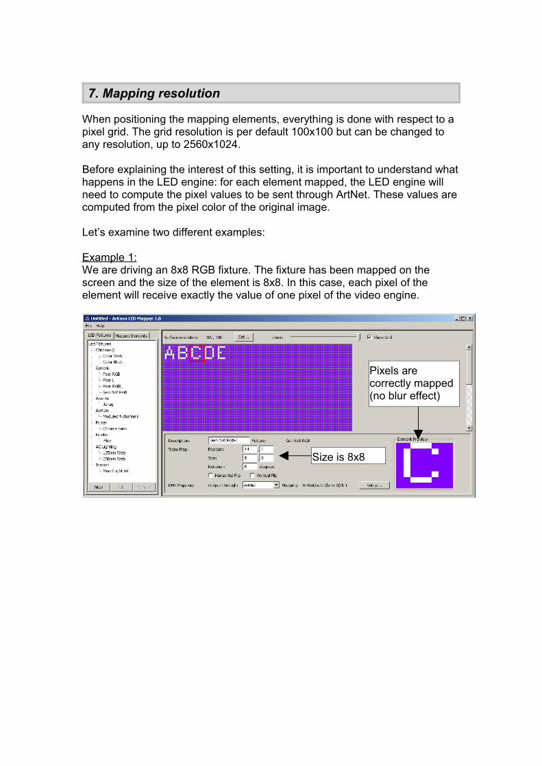
Example 1:We are driving an 8x8 RGB fixture. The fixture has been mapped on the screen and the size of the element is 8x8. In this case, each pixel of the element will receive exactly the value of one pixel of the video engine.
Pixels are correctly mapped (no blur effect)
Size is 8x8
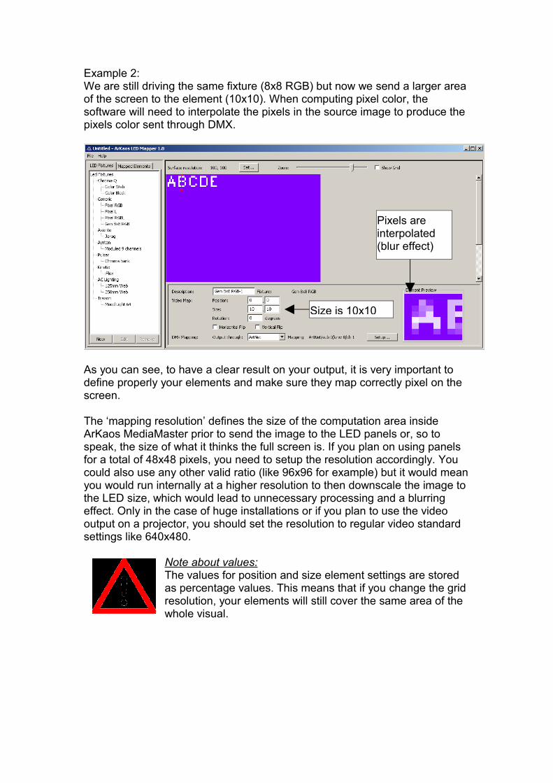
Example 2:We are still driving the same fixture (8x8 RGB) but now we send a larger area of the screen to the element (10x10). When computing pixel color, the software will need to interpolate the pixels in the source image to produce the pixels color sent through DMX.
As you can see, to have a clear result on your output, it is very important to define properly your elements and make sure they map correctly pixel on the screen.
The ‘mapping resolution’ defines the size of the computation area inside ArKaos MediaMaster prior to send the image to the LED panels or, so to speak, the size of what it thinks the full screen is. If you plan on using panels for a total of 48x48 pixels, you need to setup the resolution accordingly. You could also use any other valid ratio (like 96x96 for example) but it would mean you would run internally at a higher resolution to then downscale the image to the LED size, which would lead to unnecessary processing and a blurring effect. Only in the case of huge installations or if you plan to use the video output on a projector, you should set the resolution to regular video standard settings like 640x480.
Note about values:The values for position and size element settings are stored as percentage values. This means that if you change the grid resolution, your elements will still cover the same area of the whole visual.
Size is 10x10
Pixels are interpolated (blur effect)

8. Project files
When you have mapped all the fixtures for your show, you have to save the mapping file before leaving the application. The File menu offers all common entries:
New: creates an empty projectSave: saves the current projectSave As: saves the project under another file name
The file extension is “.lmp” which stands for LED Mapper Project. It includes the mapping (mapped elements and their properties) as well as the fixtures used in this mapping, so that you can open the file on another computer even if the fixture is not available on that computer’s fixture library.

9. Enabling LED Output in ArKaos MediaMaster
In ArKaos MediaMaster, enter the Preferences (menu File / Preferences), and open the “LED Output” tab. Check the “Activate” option to activate LED output. Use the button below to choose the LMP file to use.
Once the LED output has been activated, ArKaos MediaMaster will start broadcasting the LED information on the ArtNet output, according to the selected mapping file. It couldn’t be simpler. If you have connected and checked the LED panels while building your mapping file in the LED Mapper application, you are guaranteed to send seamlessly any video loop, image, camera output directly from ArKaos to the panels.

Support, Information and Contact
ArKaos Users Forum :http://forum.arkaos.net/
ArKaos Support Centre :http://support.arkaos.net/
1. Solutions
As always, our support team is ready to help you if you should encounter any problem upgrading to the new version.
1.1. ArKaos Users Forum
If you just want to discuss with other ArKaos users, share tips and experiences about our products or third party software / hardware etc.. Our Users Forum is the place to be ! (This is not the place to request for help, see below).
1.2. Knowledgebase articles
Our online Support Centre features a FAQ / Knowledgebase where a solution to the most common registration / configuration problems has been posted.
1.3. Trouble Ticket System
Our online Support Centre also features a Trouble Ticket System which allows our team to receive your support requests and follow up the resolution of your problem as well as eventual future issues. We strongly recommend that you register for an ArKaos Support Account (free) on our Support Centre in order to be able to check the status of your trouble tickets, post replies to our team or create new trouble tickets directly from our web interface.
Our support team answers your requests during office hours (CET) on week days, we do our very best to answer your trouble tickets within one business day.
2. Distributors and resellers
Our distributors and resellers are also at your service if you would like to request information in your language, advice on additional hardware or software, solutions or quotes for a particular configuration etc.. A complete list of distributors and resellers for ArKaos MediaMaster can be found on our web site at http://www.arkaos.net/distributors.php
Thank you very much for your interest in our products, we hope you will enjoy using this version as much as we enjoyed creating it!The ArKaos Team

The information in this document is subject to change without notice and does not represent a commitment on the part of ArKaos S.A. No part of this publication may be copied, reproduced or otherwise transmitted or recorded, for any purpose, without prior written permission by ArKaos S.A.
All product and company names are ™ or © trademarks of their respective owners.
© ArKaos S.A. 2008. All rights reserved.


