29
ARM 2007 [email protected] Chapter 10 Firmware Optimization Technique in Embedded System (AR M) [email protected], 2008 April
| Date post: | 14-Dec-2015 |
| Category: |
Documents |
| Upload: | jevon-applin |
| View: | 246 times |
| Download: | 3 times |

ARM 2007 [email protected]
Chapter 10
Firmware
Optimization Technique in Embedded System (ARM)[email protected], 2008 April
ARM 2007 [email protected]
Overview
• Firmware is an important part of any embedded system– Since it is frequently the first code to be ported and executed o
n a new platform.– Firmware can vary from being a complete software embedded
system to just a simple initialization and Bootloader routine.
• Agenda– Firmware & Bootloader– General Process of a firmware– ARM Firmware Suite– Redboot (Redhat)– Sandstone (Sloss)
ARM 2007 [email protected]
Definitions
• We realize that the use of terms may differ among engineers, but we will use the following definitions
– The firmware : an interface between the hardware and the application/operating system level software. » It resides in the ROM and executes when power is
applied to the embedded hardware system.» It can remain active after initialization to support basic
system operation.
– The bootloader is a small application that installs the operating system or applications onto a hardware target.» The bootloader only exists up to the point that the
operating system or application is executing, and it is commonly incorporated into the firmware.

ARM 2007 [email protected]
Abstraction of Firmware Execution Flow
• To help understand the features of different firmware implementations, we have a common execution flow.
ARM 2007 [email protected]
I-a. Identify the platform
• It’s common for the same executable to operate on different cores and platforms.– In this case, the firmware has to identify and
discover the exact core and platform it is operating on.» CP15:r0 = processor type, manufacture
name» Platform identification: a set of particular
peripheral.

ARM 2007 [email protected]
I-b. Diagnosing
• Diagnostics software provide a useful way for quickly identifying basic hardware malfunctions.
• Debug capability is provided in the form of a module or monitor.– Setting up breakpoints in RAM;– Listing and modifying memory (peek & poke);– Showing current processor register contents;– Disassembling memory into ARM or Thumb mnemonics.
• Interactive method– CLI (command line interpreter) (via RS-232)– A dedicated host debugger (via LAN + C/S)
• Unless the firmware has access to the internal hardware debug circuitry, only RAM image can be debugged through a software debug mechanism.
ARM 2007 [email protected]
II. HAL
• The second stage is to abstract the hardware.– The Hardware Abstraction Layer (HAL) is a
software layer that hides the underlying hardware by providing a set of defined programming interfaces.
– The HAL software that communicates with specific hardware peripheral is call a device driver.» A device driver provides a standard
application programming interface (API) to read and write to a specific peripheral.
ARM 2007 [email protected]
III. Load a bootable image
• The ability of firmware to carry out this activity depends upon the type of media used to store the image.– Note that NOT all operating system images or
application images need to be copied into RAM, they could be executed directly from ROM (XIP).
– FFS: flash ROM filing system.– Network File System
• Image Format– Plain binary: doesn’t contain any header or debug
information.– Executable and Linking Format (ELF)
» developed for UNIX, and replaced the COFF.» ELF files come in three forms: relocatable,
executable, and shared object.– Compressed image
ARM 2007 [email protected]
IV. Relinquish Control
• This is where the firmware hands over control of the platform to an operating system or application.– Note that NOT all firmware hands over control.
Alternatively, the MIL or HAL part of firmware can remain active. This layer expose, through SWI mechanism, a standard application interface for specific hardware devices.
• Relinquishing control means– Updating the vector table and modifying the PC.– Passing Environment Data Structure (EDS) to
some sophisticated OS, e.g., Linux.» EDS fields: memory size, MMU type, etc.
ARM 2007 [email protected]
10.1.1 ARM Firmware Suite
• ARM Firmware Suite (AFS)– Support ARM processors including Intel’s Xscale and StrongA
RM– Two technologies: uHAL and Angel (monitor)
• micro-HAL and API– Initializing, UART Driver, LED Control (for Indicating)– Timer (for preemptive context switching)– Interrupt Controller (IC) (many types supported)
• Angel– Comm. between host and target (debug/develop )– CLI (for command)– APIs (via SWI)

ARM 2007 [email protected]
10.1.2 Redboot
• RedBoot– Redhat, Open Source License– CPU: ARM, MIPS, SH– HAL is heart of Redboot
• It provide both GDB (debug) and Bootloader• RedBoot supports three main features
– Communication: X-Modem, TCP, bootp, telnet, tftp– Flash Management: Download, Update, Flush– Full OS Support: Linux, eCos (Redhat)
» Passing parameters

ARM 2007 [email protected]
A Real Case: Sandstone
• It carries out only the following task (simple) – Setting up target platform;
– Loading a bootable image;
– Relinquish control to OS.
• Implementation– It is specific to the ARM Evaluator-7T platform.
– This example shows you How a simple platform be set.
ARM 2007 [email protected]
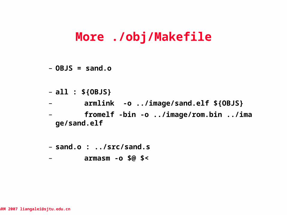
More ./obj/Makefile
– OBJS = sand.o
– all : ${OBJS}– armlink -o ../image/sand.elf ${OBJS}– fromelf -bin -o ../image/rom.bin ../image/sand.
elf
– sand.o : ../src/sand.s– armasm -o $@ $<
ARM 2007 [email protected]
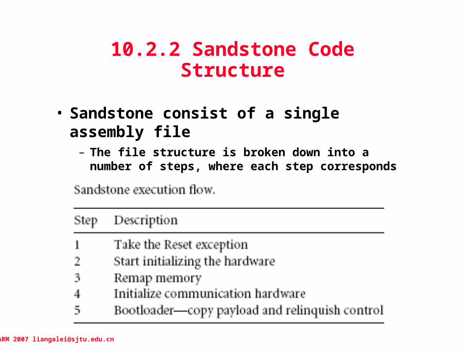
10.2.2 Sandstone Code Structure
• Sandstone consist of a single assembly file– The file structure is broken down into a number
of steps, where each step corresponds to a stage in the execution flow of Sandstone.
ARM 2007 [email protected]
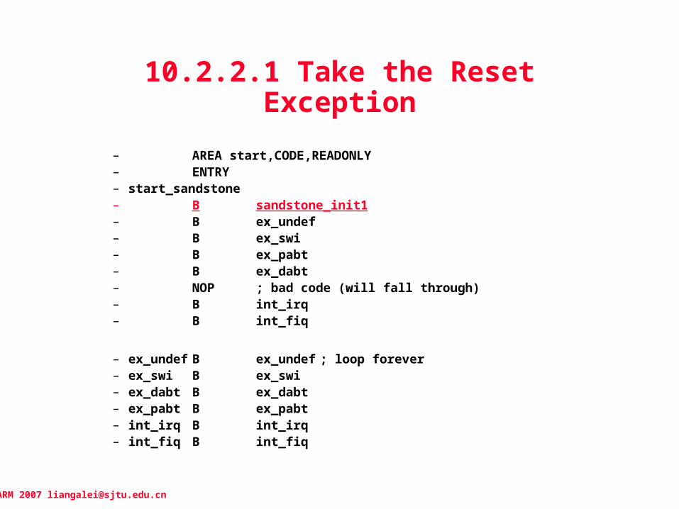
10.2.2.1 Take the Reset Exception
– AREA start,CODE,READONLY– ENTRY– start_sandstone– B sandstone_init1– B ex_undef– B ex_swi– B ex_pabt– B ex_dabt– NOP ; bad code (will fall through)– B int_irq– B int_fiq
– ex_undef B ex_undef ; loop forever– ex_swi B ex_swi– ex_dabt B ex_dabt– ex_pabt B ex_pabt– int_irq B int_irq– int_fiq B int_fiq
ARM 2007 [email protected]
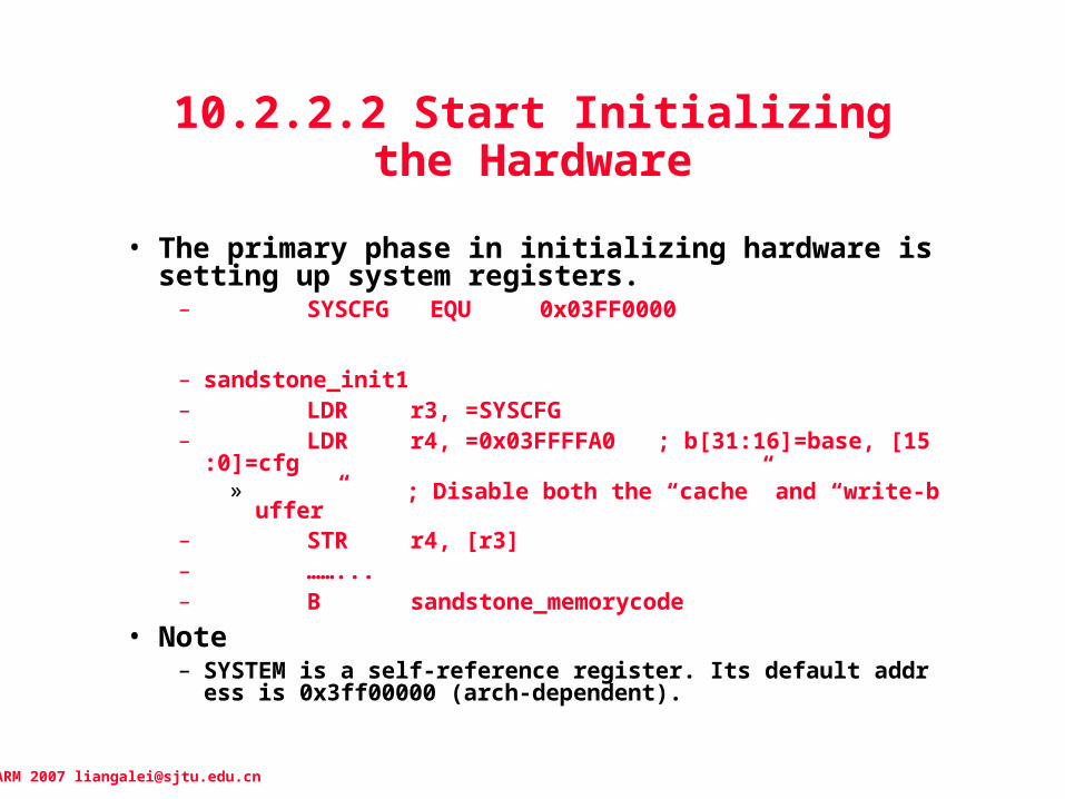
10.2.2.2 Start Initializing the Hardware
• The primary phase in initializing hardware is setting up system registers.– SYSCFG EQU 0x03FF0000
– sandstone_init1– LDR r3, =SYSCFG– LDR r4, =0x03FFFFA0 ; b[31:16]=base, [15:0]=cfg
» ; Disable both the “cache” and “write-buffer”– STR r4, [r3]– ……...– B sandstone_memorycode
• Note– SYSTEM is a self-reference register. Its default address is 0x3ff0
0000 (arch-dependent).
ARM 2007 [email protected]
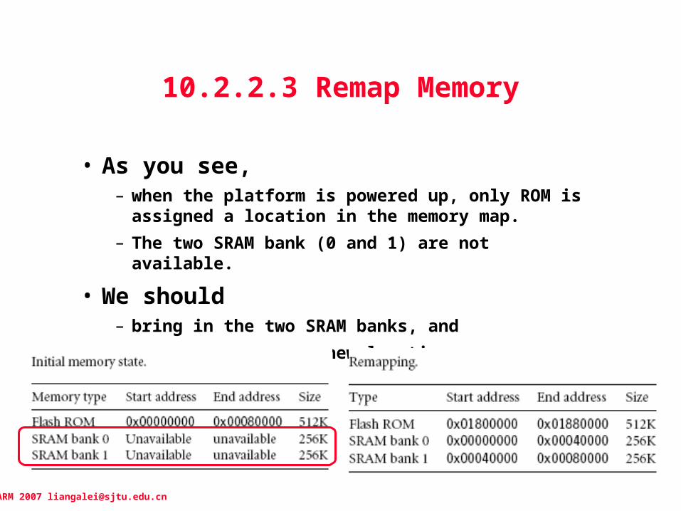
10.2.2.3 Remap Memory
• As you see, – when the platform is powered up, only ROM is
assigned a location in the memory map.
– The two SRAM bank (0 and 1) are not available.
• We should – bring in the two SRAM banks, and
– remap the ROM to a new location

ARM 2007 [email protected]
Remap the ROM, and Setup SRAM
– LDR lr, =sandstone_init2– LDR r4, =0x1800000– ADD lr,lr,r4 ; calculate the absolute address– ADRL r0, memorymaptable_str ; get address of table– LDMIA r0, {r1-r12}– LDR r0, =EXTDBWTH ; =(SYSCFG + 0x3010)– STMIA r0, {r1-r12} ; setup DBus Width– MOV pc, lr ; JUMP to remapped memory
– memorymaptable_str– DCD rEXTDBWTH ; ROM0(Half), ROM1(Word), ROM1(Word), rest Disabled– DCD rROMCON0 ; 0x1800000 ~ 0x1880000, RCS0, 4Mbit, 4cycle, ROM– DCD rROMCON1 ; 0x0000000 ~ 0x0040000, RCS1, 256KB, 2cycle, SRAM1– DCD rROMCON2 ; 0x0040000 ~ 0x0080000, RCS2, 256KB, 2cycle, SRAM2
• * Question: Here, ROM has already remapped to higher memory space, how can this instruction “MOV pc, lr” be fetched?
(*)

ARM 2007 [email protected]
10.2.2.4 Initialize Communication Hardware
• Communication initialization involves– Configuring a serial port, and
– Outputting a banner message on console
• The serial port is set to– 9600 baud, no parity, one stop bit, and no flow
control

ARM 2007 [email protected]
UART (1)
– sandstone_init2– B sandstone_serialcode
– sandstone_serialcode– // UART Control: Clearing– LDR r1, =UART0_BASE– ADD r1, r1,#UCON– MOV r2, #0– STR r2, [r1]
– // Line Control: 7/8-bit, 1/1.5-Stop, No/Odd/Even-Parity – LDR r1, =UART0_BASE– ADD r1, r1,#ULCON– MOV r2, #ULCR8bits– STR r2, [r1]

ARM 2007 [email protected]
UART (2)
– // UART Control: Loop-back, DMA, INT, Tx/Rx Enable– LDR r1, =UART0_BASE– ADD r1, r1, #UCON– MOV r2, #(UCRRxM | UCRTxM)– STR r2, [r1]–
– // Baud-Rate – LDR r1, =UART0_BASE– ADD r1, r1, #UBRDIV– MOV r2, #(BAUD_9600)– STR r2, [r1]
ARM 2007 [email protected]
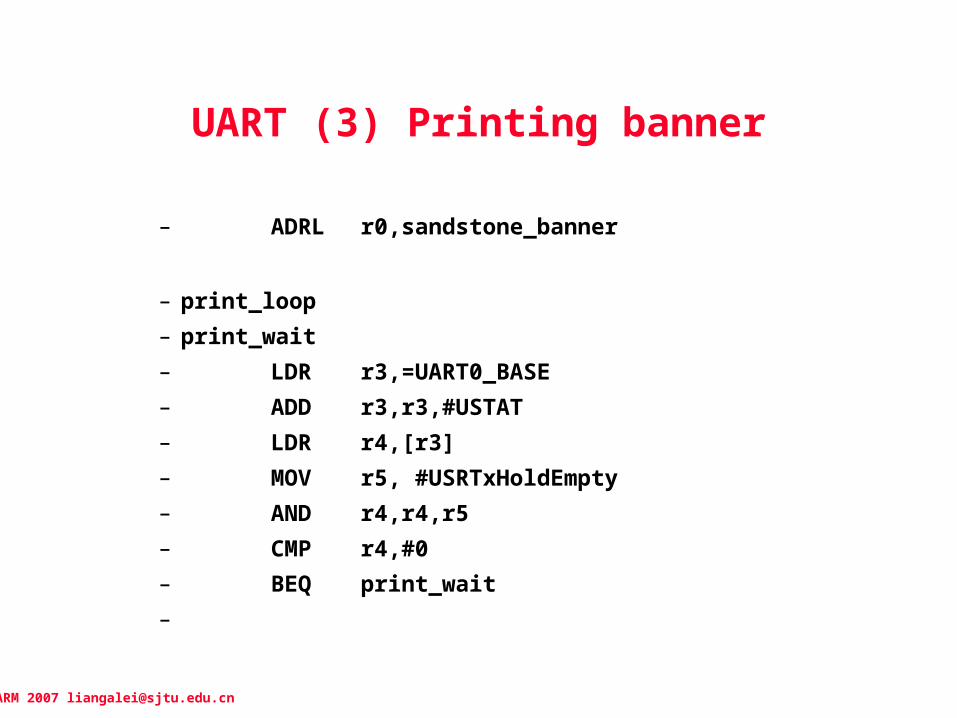
UART (3) Printing banner
– ADRL r0,sandstone_banner
– print_loop– print_wait– LDR r3,=UART0_BASE– ADD r3,r3,#USTAT– LDR r4,[r3]– MOV r5, #USRTxHoldEmpty– AND r4,r4,r5– CMP r4,#0– BEQ print_wait–
ARM 2007 [email protected]
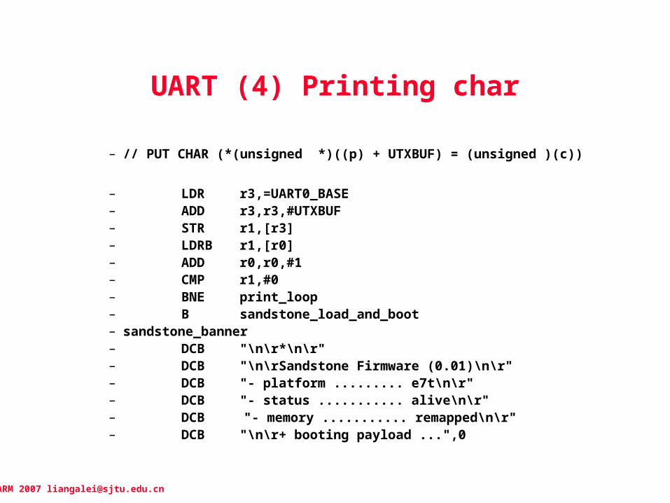
UART (4) Printing char
– // PUT CHAR (*(unsigned *)((p) + UTXBUF) = (unsigned )(c))
– LDR r3,=UART0_BASE– ADD r3,r3,#UTXBUF– STR r1,[r3]– LDRB r1,[r0]– ADD r0,r0,#1– CMP r1,#0– BNE print_loop– B sandstone_load_and_boot – sandstone_banner– DCB "\n\r*\n\r"– DCB "\n\rSandstone Firmware (0.01)\n\r"– DCB "- platform ......... e7t\n\r"– DCB "- status ........... alive\n\r"– DCB "- memory ........... remapped\n\r"– DCB "\n\r+ booting payload ...",0

ARM 2007 [email protected]
10.2.2.5 BootloaderCopy Payload and Relinquish Control
– ALIGN 4
– sandstone_load_and_boot
– // Section 1 : Copy payload to address 0x00000000
– MOV r13,#0 ; destination addree
– LDR r12,payload_start_address ; start address– LDR r14,payload_end_address ; end address– block_copy– LDMIA r12!,{r0-r11}– STMIA r13!,{r0-r11}– CMP r12,r14– BLE block_copy
ARM 2007 [email protected]
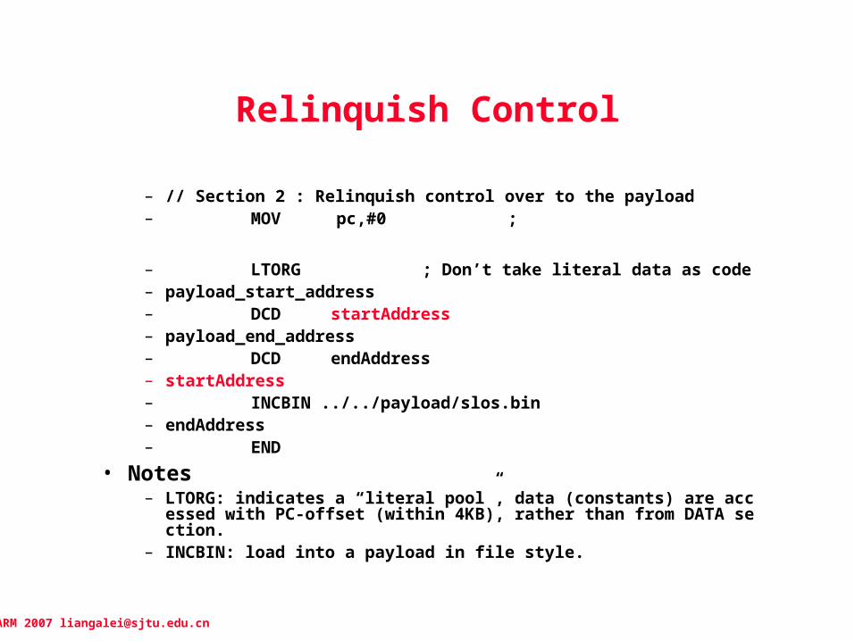
Relinquish Control
– // Section 2 : Relinquish control over to the payload– MOV pc,#0 ;
– LTORG ; Don’t take literal data as code– payload_start_address– DCD startAddress– payload_end_address– DCD endAddress– startAddress– INCBIN ../../payload/slos.bin– endAddress– END
• Notes– LTORG: indicates a “literal pool”, data (constants) are accessed with
PC-offset (within 4KB), rather than from DATA section.– INCBIN: load into a payload in file style.

ARM 2007 [email protected]
10.3 Summary
• This chapter covered the firmware– We define firmware as the low-level code that interfaces the
hardware with an application or operating system.– We also define bootloader as the software that loads an
operating system or application into memory and relinquishes control of the PC to that software.
– We introduced the ARM Firmware Suite (AFS) and RedBoot.– Next, we looked at a firmware example called Sandstone.
» Sandstone initialized the hardware and then loads and boots an image following this procedure:
• Take the reset exception• Starts initializing the hardware; sets the system register’s base address
and initializes segment display hardware.• Remaps memory; ROM address = high, and SRAM addr = 0x00000000.• Initializes the communication hardware output on the serial port.• Bootloader – loads an image into SRAM and relinquishes control of the PC
to the image (PC=0x00000000).
• We now have a fully initialized ARM7TDMI embedded system.