12
ARM HOW-TO GUIDE Interfacing Relay with LPC2148 ARM

ARM HOW-TO GUIDE
Interfacing Relay with
LPC2148 ARM

Join the Technical Community Today!
http://www.pantechsolutions.net
Contents at a Glance
ARM7 LPC2148 Primer Board ........................................... 3
Relay ............................................................................... 3
Interfacing Relays ............................................................ 4
Interfacing Relay with LPC2148 ........................................ 5
Pin Assignment with LPC2148 .......................................... 5
Circuit Diagram to Interface Relay with LPC2148 .............. 6
Source Code .................................................................... 6
C Program to control Relay in LPC2148 ............................. 7
Testing the LED with LPC2148 .......................................... 8
General Information ........................................................ 9

Join the Technical Community Today!
http://www.pantechsolutions.net
ARM7 LPC2148 Primer Board
The ARM7 LPC2148 Primer board is specifically
designed to help students to master the required skills in
the area of embedded systems. The kit is designed in such
way that all the possible features of the microcontroller will
be easily used by the students. The kit supports in system
programming (ISP) which is done through serial port.
NXP’s ARM7 (LPC2148), ARM Primer Kit is proposed to
smooth the progress of developing and debugging of
various designs encompassing of High speed 32-bit
Microcontrollers.
Relay
Relays are devices which allow low power circuits to
switch a relatively high Current/Voltage ON/OFF. A relay
circuit is typically a smaller switch or device which drives
(opens/closes) an electric switch that is capable of carrying
much larger current amounts.

Join the Technical Community Today!
http://www.pantechsolutions.net
Interfacing Relays
Fig. 1 shows how to interface the Relay to
microcontroller. There are 2 input channels. Each input is
connected to the triggering coil of the respective relay.
There are 2 output channels that each correspond to an
input. When the input is energized, the relay turns on and
the '+' output is connected to +12v. When the relay is off,
the '+' output is connected to Ground. The '-' output is
permanently wired to Ground.
Fig. 1 Interfacing Buzzer to Microcontroller
Join the Technical Community Today!
http://www.pantechsolutions.net
Interfacing Relay with LPC2148
We now want to control the relay operations by using
LPC2148 Primer Board. Here we are using two Relays. The
relay consists of a coil and a switch. When the coil is
energized, the switch closes, connecting the two contacts
together. ULN2803 is used as a driver for port I/O lines,
drivers output connected to relay modules. Connector
provided for external power supply if needed.
Relay Module : Port P1 pins (Realy1 – P1.20) and
Relay2-P1.21) for relay module, make port pins to high,
relay will activated.
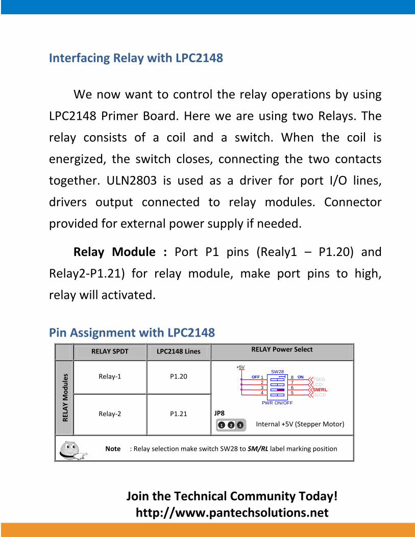
Pin Assignment with LPC2148
RELAY SPDT LPC2148 Lines RELAY Power Select
REL
AY
Mo
du
les Relay-1 P1.20
JP8
- Internal +5V (Stepper Motor)
Relay-2 P1.21
Note : Relay selection make switch SW28 to SM/RL label marking position
+5V
ONOFF
SW28
PWR ON/OFF
1234
8765
7SEGLCDSM/RLGLCD
2 3 1
Join the Technical Community Today!
http://www.pantechsolutions.net
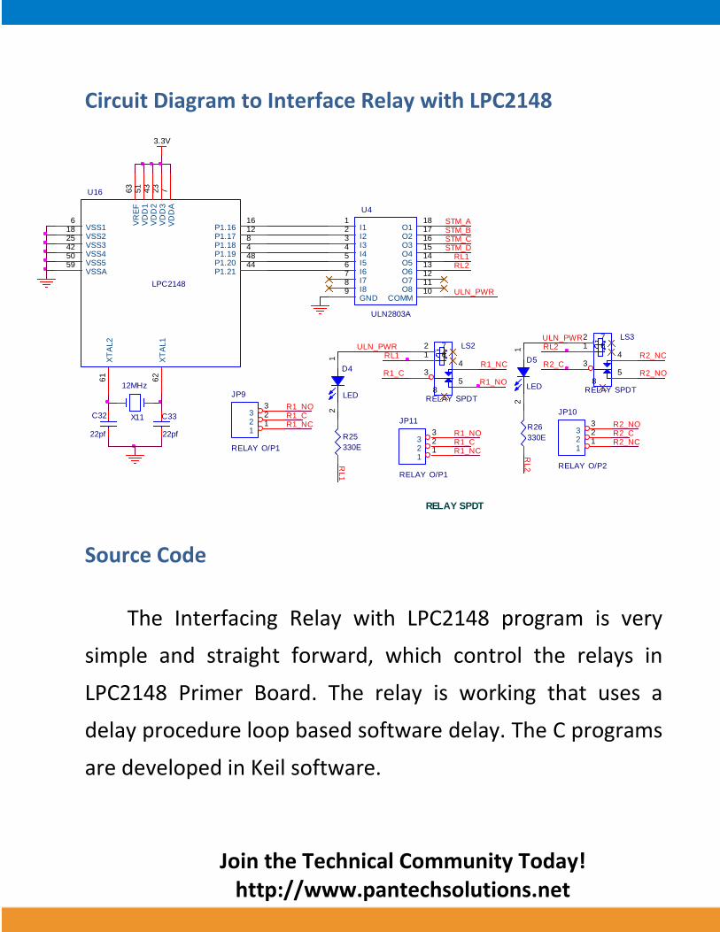
Circuit Diagram to Interface Relay with LPC2148
Source Code
The Interfacing Relay with LPC2148 program is very
simple and straight forward, which control the relays in
LPC2148 Primer Board. The relay is working that uses a
delay procedure loop based software delay. The C programs
are developed in Keil software.
STM_A
U4
ULN2803A
I11
I22
I33
I44
I55
I66
I77
I88
GND9
O118
O217
O316
O415
O514
O613
O712
O811
COMM10
STM_B
STM_DSTM_C
RL2RL1
C32
22pf
C33
22pf
X11
12MHz
3.3V
LPC2148
U16
VSS16 V
DD
A7
VSS218
VD
D3
23
VSS325
VD
D2
43
VSS442
VR
EF
63
XT
AL1
62
XT
AL2
61
VSSA59
VD
D1
51
VSS550
P1.1616
P1.1712
P1.188
P1.194
P1.2048
P1.2144
RELAY SPDT
R1_CR1_NO
JP9
RELAY O/P1
112233
R1_NC R2_NO
JP10
RELAY O/P2
112233
R2_NCR2_C
LS3
RELAY SPDT
35
412
67
8
R2_NC
R2_NO
ULN_PWR
R26
330E
RL2
D5
LED
12
R2_C
RL2
ULN_PWR
R1_NO
JP11
RELAY O/P1
112233
R1_NCR1_C
LS2
RELAY SPDT
35
412
67
8
R1_NCR1_C
R25
330E
RL1
D4
LED
12
ULN_PWR
R1_NO
RL1
Join the Technical Community Today!
http://www.pantechsolutions.net
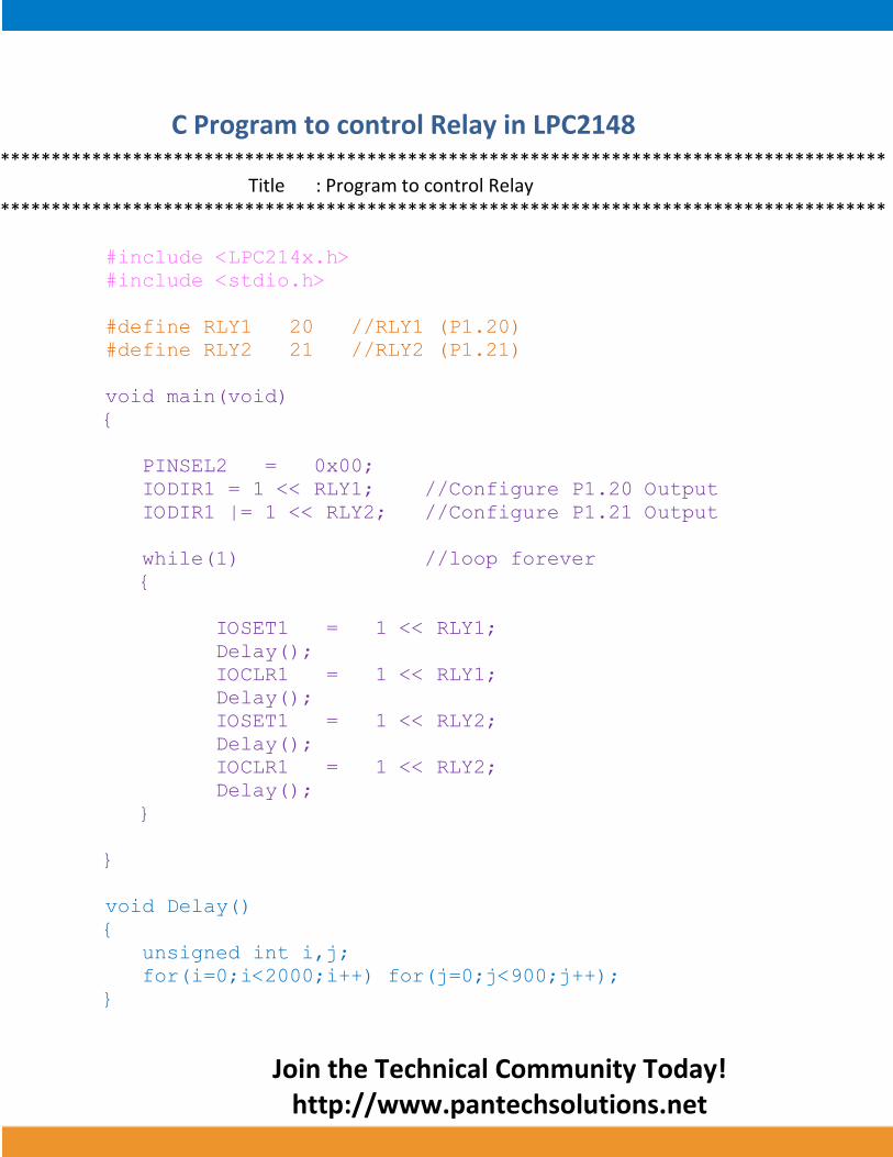
C Program to control Relay in LPC2148 ***************************************************************************************
Title : Program to control Relay ***************************************************************************************
#include <LPC214x.h>
#include <stdio.h>
#define RLY1 20 //RLY1 (P1.20)
#define RLY2 21 //RLY2 (P1.21)
void main(void)
{
PINSEL2 = 0x00;
IODIR1 = 1 << RLY1; //Configure P1.20 Output
IODIR1 |= 1 << RLY2; //Configure P1.21 Output
while(1) //loop forever
{
IOSET1 = 1 << RLY1;
Delay();
IOCLR1 = 1 << RLY1;
Delay();
IOSET1 = 1 << RLY2;
Delay();
IOCLR1 = 1 << RLY2;
Delay();
}
}
void Delay()
{
unsigned int i,j;
for(i=0;i<2000;i++) for(j=0;j<900;j++);
}

Join the Technical Community Today!
http://www.pantechsolutions.net
To compile the above C code you need the KEIL
software. They must be properly set up and a project with
correct settings must be created in order to compile the
code. To compile the above code, the C file must be added
to the project.
In Keil, you want to develop or debug the project
without any hardware setup. You must compile the code for
generating HEX file. In debugging Mode, you want to check
the port output without LPC2148 Primer Board.
The Flash Magic software is used to download the hex
file into your microcontroller IC LPC2148 through UART0.
Testing the LED with LPC2148
Give +3.3V power supply to LPC2148 Primer Board; the
Relay module is connected with LPC2148 Primer Board.
When the program is downloading into LPC2148 in Primer
Board, the Relay output is working that the Relay is ON

Join the Technical Community Today!
http://www.pantechsolutions.net
some time period and the Relay is OFF some other time of
period.
If you are not getting any output from Relay, then you
just check the jumper connections & check the Relay is
connected properly. Otherwise you just check it with
debugging mode in Keil. If you want to see more details
about debugging just see the videos in below link.
How to Create & Debug a Project in Keil.
General Information
For proper working use the components of exact values
as shown in Circuit file. Wherever possible use new
components.
Solder everything in a clean way. A major problem
arises due to improper soldering, solder jumps and
loose joints.
Use the exact value crystal shown in schematic.
More instructions are available in following articles,

Join the Technical Community Today!
http://www.pantechsolutions.net
User Manual of LPC2148 Primer Board.
Tutorial of how to create & Debug a project in Keil.

Join the Technical Community Today!
http://www.pantechsolutions.net
Pantech solutions creates information packed technical
documents like this one every month. And our website is a rich
and trusted resource used by a vibrant online community of
more than 1,00,000 members from organization of all shapes
and sizes.
Did you enjoy the read?

Join the Technical Community Today!
http://www.pantechsolutions.net
What do we sell?
Our products range from Various Microcontroller
development boards, DSP Boards, FPGA/CPLD boards,
Communication Kits, Power electronics, Basic electronics,
Robotics, Sensors, Electronic components and much more . Our
goal is to make finding the parts and information you need
easier and affordable so you can create awesome projects and
training from Basic to Cutting edge technology.


