12
ARM Timers
| Date post: | 28-Dec-2015 |
| Category: |
Documents |
| Upload: | clyde-shelton |
| View: | 220 times |
| Download: | 0 times |
ARM Timers

What are Timers ?
Timers are hardware Counters that can be configured to run from a variety of internal or external clocks.
They run concurrently with CPU and can be configured in software to provide a bewildering variety of functions.
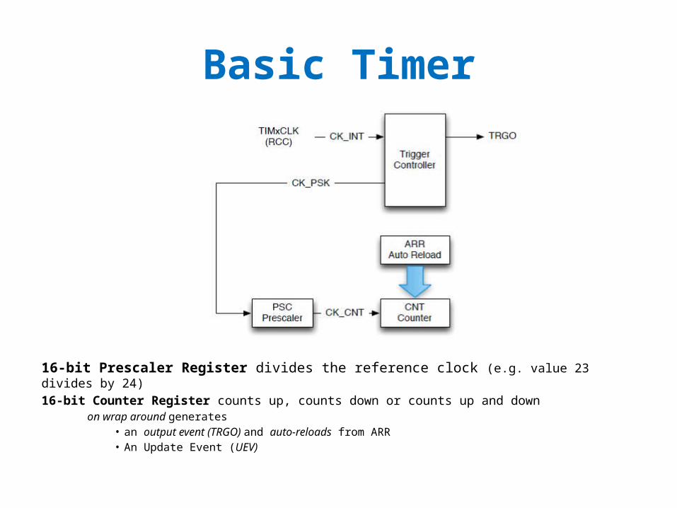
Basic Timer
16-bit Prescaler Register divides the reference clock (e.g. value 23 divides by 24)16-bit Counter Register counts up, counts down or counts up and down on wrap around generates
• an output event (TRGO) and auto-reloads from ARR• An Update Event (UEV)
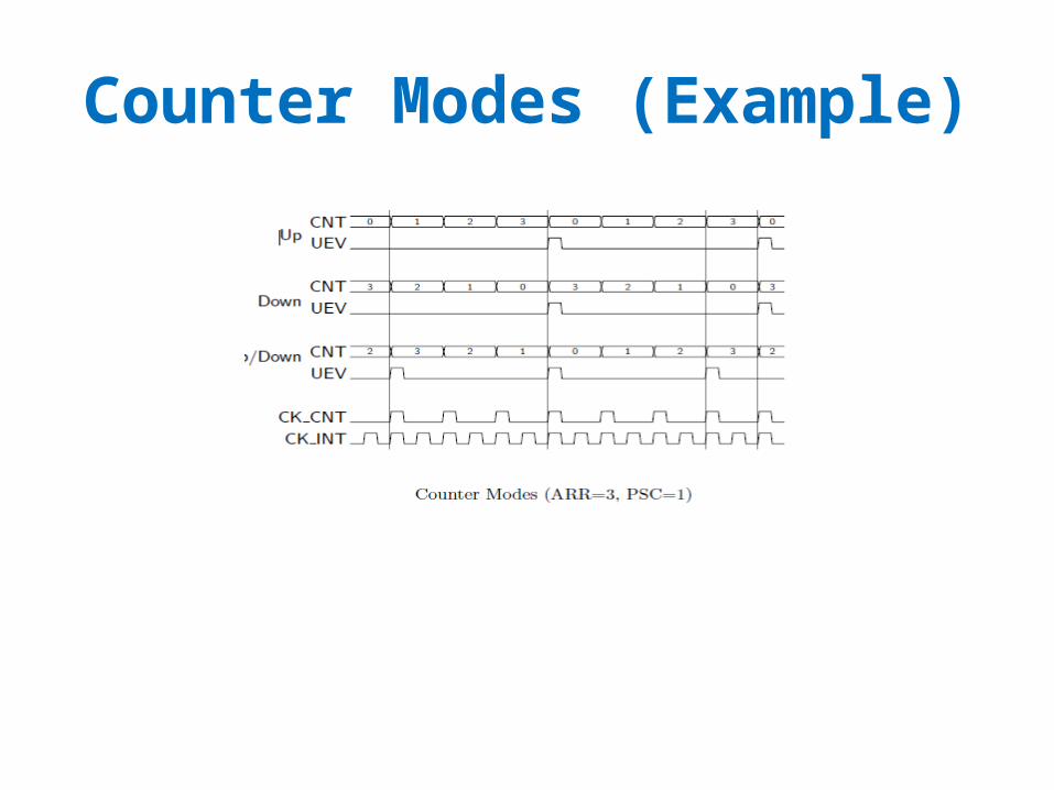
Counter Modes (Example)

Example:Timer3 Toggles LED at One Second intervals.
// Assume CPU configured to run at system clock frequency 24 MHz.// GPIO driving LED has been configured for output and its clock enabled.#include "stm32f10x.h“ // Contains definitions of Timer structure
RCC->APB1ENR |= RCC_APB1ENR_TIM3EN; // enable clock for timer TIM3 : TIM3->PSC = 23999; // Set pre-scaler to 24 000 (PSC + 1)
TIM3->ARR = 1000; // Auto reload value 1000TIM3->CR1 = TIM_CR1_CEN; // Enable timer
// When timer reaches the ARR value, the UIF flag will be set. Check this flag, clear it// and toggle an LED : while(1){ if(TIM3->SR & TIM_SR_UIF)
{ TIM3->SR &= ~TIM_SR_UIF; LED_BLUE_GPIO->ODR ^= (1 << LED_BLUE_PIN); }
}

Capture and Compare Register (CCR)
CCR is based on a Timer Register plus additional hardware.CCR can be configured for either Capture or Compare modes:
• Capture mode operates as a stop watch – You start the stop watch – The stop watch runs while you wait for an event(s) to happen – Once the event(s) happen the stop watch is stopped and the time is recorded
• Compare mode operates as a comparator -You set a predefined value - Start the register to count incoming pulses - Once the pre-defined value is reached it generates an output event
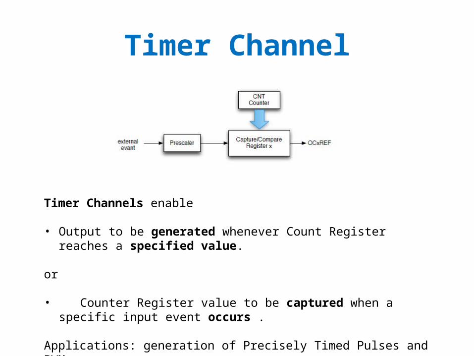
Timer Channel
Timer Channels enable • Output to be generated whenever Count Register reaches a specified value.
or
• Counter Register value to be captured when a specific input event occurs .
Applications: generation of Precisely Timed Pulses and PWM

Pulse Width Modulation (PWM)
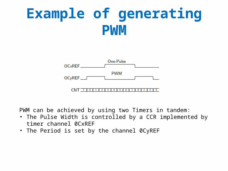
Example of generating PWM
PWM can be achieved by using two Timers in tandem:• The Pulse Width is controlled by a CCR implemented by timer channel 0CxREF• The Period is set by the channel 0CyREF

Input Capture: Ultrasonic Ranger
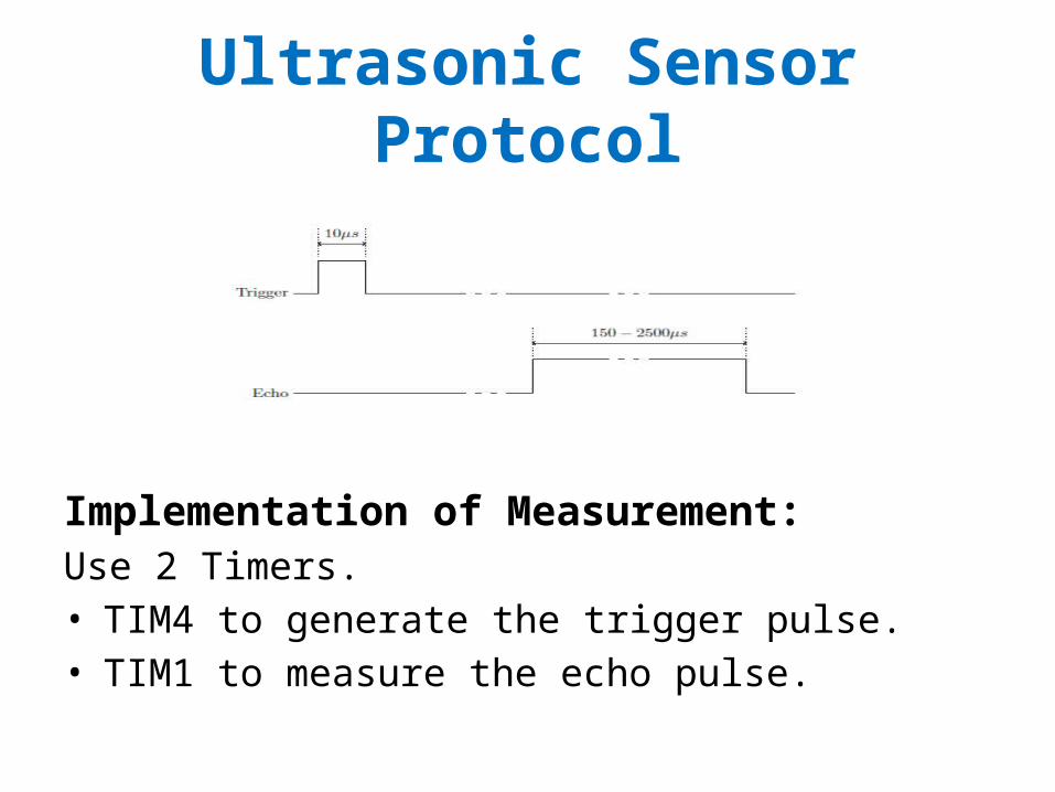
HC-SR04 ultrasonic module:• 3mm resolution in the range 20-500 mm• Ultrasonic Pulse triggered by delivering to it a 10 us pulse• Generates an 8 pulse 40 kHz signal driving the Ultrasonic transducer• Distance determined as a Pulse Width obtained from PWM module output. distance = pulse width * 58x10-6 [cm]
Ultrasonic Sensor Protocol
Implementation of Measurement:Use 2 Timers. • TIM4 to generate the trigger pulse.• TIM1 to measure the echo pulse.
Outline of Measuring Algorithm
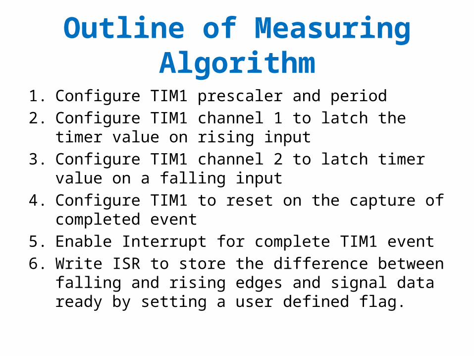
1. Configure TIM1 prescaler and period2. Configure TIM1 channel 1 to latch the timer value on rising
input3. Configure TIM1 channel 2 to latch timer value on a falling
input4. Configure TIM1 to reset on the capture of completed event5. Enable Interrupt for complete TIM1 event6. Write ISR to store the difference between falling and rising
edges and signal data ready by setting a user defined flag.


