63
Final Alexand Mechan Advisor April 7, Thesis der Hosko nical Optio r: Dr. Tread 2011 Arm New s Repor on do my Res port, rt serve Rhod Cent de Isla ter and

Final AlexandMechanAdvisorApril 7,
Thesis
der Hosko nical Optior: Dr. Tread2011
ArmNew
s Repor
on do
my Resport,
rt
serveRhod
Centde Isla
ter and

Alexander MechanicaAdvisor: D
Alexander
Hosko al Option r. Treado
Hosko Finall Thesis Reportt April 77, 2011
2

Alexander Hosko 3 Mechanical Option Advisor: Dr. Treado
Alexander Hosko Final Thesis Report April 7, 2011
Table of Contents
Credits / Acknowledgements 5 Executive Summary 6 General Building Data 7 Architecture 7 Zoning 7 Building Enclosure 7 Primary Wall System 7 Second Floor and Up 8 Roofing 9 Windows / Doors 9 Sustainability Features 9 Construction 9 Electrical 9 Lighting 9 Structural 9 Fire Protection 10 Transportation 10 Telecom 10 Existing Variable Air Volume (VAV) System 11 Airside 11 Waterside 12 Schematic Drawings of Existing Mechanical Systems 13 Summary of Major Equipment 15 Lost Space Due to Mechanical Systems 16 Annual Energy Use 17 Fuel Costs 18 Total Cost 19 ASHRAE Standard 62.1 Analysis 20 ASHRAE Standard 90.1 Analysis 21 Existing Mechanical Systems Conclusion 21 Mechanical System Redesign 23 Variable Refrigerant Flow 23 Ground Couple Heat Pump 23 Dedicated Outdoor Air System 23 Breadth Topics 24 Acoustical Breadth 24 Structural Breadth 24 Integration and Coordination 24 Variable Refrigerant Flow (VRF) with Dedicated Outdoor Air (DOAS) 25

Alexander Hosko 4 Mechanical Option Advisor: Dr. Treado
Alexander Hosko Final Thesis Report April 7, 2011
Load Analysis 26 Airflow 27 Lighting 27 Schedules 27 Occupancy 28 Indoor / Outdoor Air Conditions 28 Results 29 Annual Energy Use 32 Fuel Costs 33 Total Cost 33 Lost Space due to Mechanical Systems 34 LEED 34 Greenhouse Gases 34 Ground Couple Heat Pump (GCHP) with Dedicated Outdoor Air (DOAS) 35 Load Analysis 37 Assumptions 37 Sizing the GCHP 37 Vertical 38 Horizontal 42 Space Requirements: Horizontal or Vertical Use 43 Annual Energy Use 43 Fuel Costs 44 Total Cost 45 Lost Space due to Mechanical Systems 45 LEED 45 Greenhouse Gases 46 Structural Breadth 47 Acoustical Breadth 50 System Comparison and Recommendation 54 References 56 Appendix A 57 Appendix B 61
Alexander Hosko 5 Mechanical Option Advisor: Dr. Treado
Alexander Hosko Final Thesis Report April 7, 2011
Credits / Acknowledgements
The Pennsylvania State University Architectural Engineer Faculty and Staff
Thesis Advisor: Dr. Stephen Treado
Michael Baker Corporation: Specifically Duncan Penney and Doug Barker
U.S. Army Corps of Engineers
Family and Friends for their support

Alexander Hosko 6 Mechanical Option Advisor: Dr. Treado
Alexander Hosko Final Thesis Report April 7, 2011
Executive Summary
The main goal in designing the Army Reserve Center was to achieve a LEED Silver or Gold certification while maintaining good design practices such as following the applicable codes and following the requests of the United States Army Corps of Engineers. The codes that were followed were the American Society of Heating, Refrigeration and Air‐Conditioning Engineers (ASHRAE) Standard 62.1 and 90.1, the United Facilities Criteria (UFC) 4‐171‐05 and 3‐400‐02, and all applicable National Fire Protection Association (NFPA) codes and standards. To achieve this goal, a constant volume air handling unit was used for the auditorium, two variable air volume air handling units were used for the entire second floor and the core of the first floor, and smaller unit ventilators met the loads and ventilation requirements for the classrooms on the first floor and several other smaller zones on the first floor. In order to make the Army Reserve Center more energy efficient, a variable refrigerant flow (VRF) system was used to take care of the heating and sensible cooling loads. The outside air required by ASHRAE and the latent cooling load were taken care of using a dedicated outdoor air system (DOAS). Another option that was explored was the use of a DOAS to handle the latent loads and the outside air requirements and a ground couple heat pump (GCHP) to handle the remaining loads. The systems were designed based on ASHRAE Standards using Microsoft Excel for the majority of calculations with some calculations done by hand. The Army Reserve Center was modeled with these systems in place using Trane Trace 700. It was found that the best alternative for the Army Reserve Center was the combination of a DOAS system and a VRF system. This combination had the lowest first cost, saved mechanical space, and saved energy when compared to the existing VAV system. However, the combination of a GCHP and DOAS used the least amount of energy. An acoustical study and a structural study were also performed. The acoustical study involved analyzing the sound created by the rooftop condensing units for VRF system. The structural study determined the roof deck, joists, and girders that are needed to support the additional weight of the rooftop condensing units for the VRF system.
Alexander Hosko 7 Mechanical Option Advisor: Dr. Treado
Alexander Hosko Final Thesis Report April 7, 2011
General Building Data
The Army Reserve Center Training Center is located in Newport, Rhode Island and is occupied by the U.S. Army Reserve. It is 59,000 square feet of primarily offices, classrooms, and storage. There are two total stories. The project was awarded on January 15, 2009 and is estimated to be completed in September of 2011. The total cost of the project is $17 million and it is being built using the design‐bid‐built construction method.
The owner of the Army Reserve Center is the United States Government, specifically the Department of Defense represented by the U.S. Army Corps of Engineers – Louisville District. The contractor is J&J Contractors and the design team is Michael Baker.
Architecture
The building will consist mostly of white range field brick on the exterior. Bands of tan ground face block will be present with period fields of matching tan split face block to break up the long mass of the elevations. To emphasize certain transitions, light tan cast stone accents are used.
The massing of the building is meant to be simple, with a main two‐story mass, and an attached 1‐1/2 story mass which contains the assembly hall. This simple, proportional massing lends the design to be simply structured, providing maximum value for the given area program.
Zoning
The building is classified as Business Group B in the International Building Code as its primary occupancy. Its secondary occupancy consists of Assembly Group A‐3 and Storage Group S‐1 according to the International Building Code.
Building Enclosure
Primary Wall System
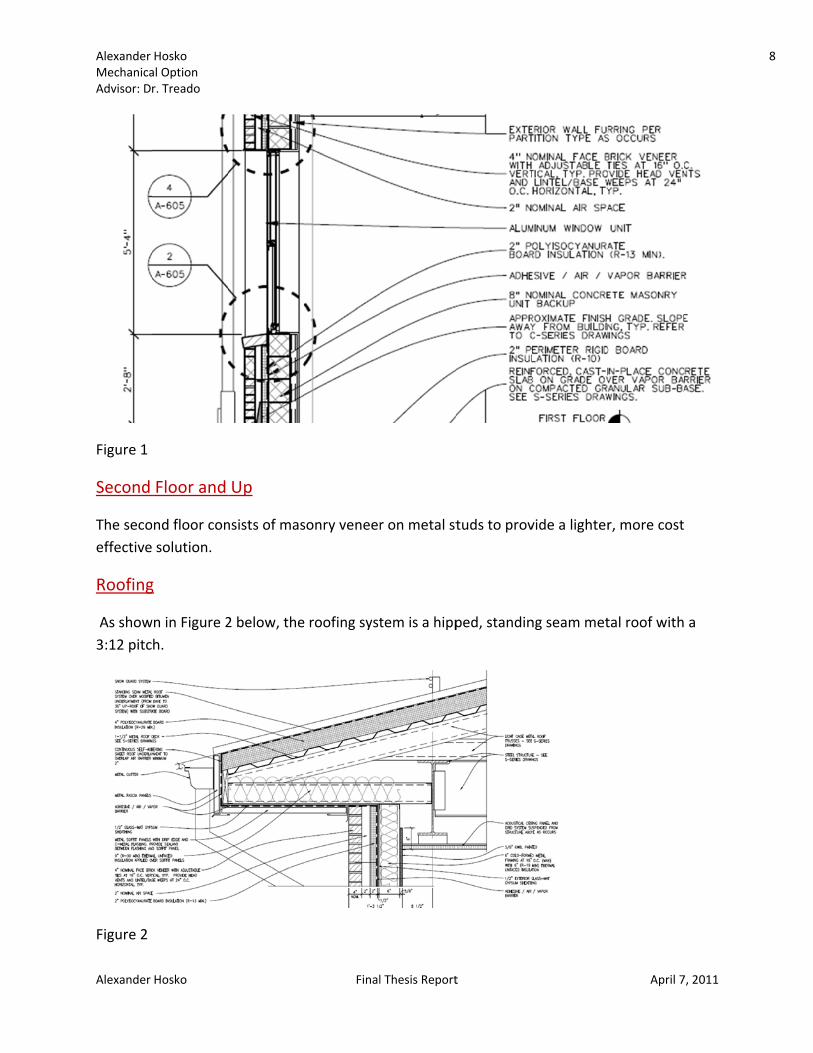
As shown in Figure 1 below, the primary wall system is a non‐load bearing, insulated masonry cavity wall with decorative concrete masonry unit (CMU) or brick masonry veneer.
Alexander MechanicaAdvisor: D
Alexander
Figure 1
Second
The secoeffective
Roofing
As show3:12 pitc
Figure 2
Hosko al Option r. Treado
Hosko
Floor and
ond floor con solution.
g
wn in Figure 2h.
Up
nsists of mas
2 below, the
Final
sonry veneer
e roofing syst
l Thesis Report
r on metal st
tem is a hipp
t
tuds to prov
ped, standin
vide a lighter
ng seam met
April 7
r, more cost
tal roof with
7, 2011
a
8

Alexander Hosko 9 Mechanical Option Advisor: Dr. Treado
Alexander Hosko Final Thesis Report April 7, 2011
Windows/Doors
The windows are anodized aluminum fixed or operable, with aluminum storefront assemblies for large expanses of glazing, and at the major entry. Other doors will be insulated, painted metal doors in hollow metal frames.
Sustainability Features
The project is going to follow LEED Version 2.2 in an attempt to be sustainable. The Army Reserve Center is projected to obtain 36 to 42 LEED points which will thus achieve LEED Silver and or Gold. To achieve this, alternative transportation, water use reduction, optimizing energy performance, and using low emitting materials are all strategies that will be employed.
Construction
The construction of the Army Reserve Center training building will be completed in the fall of 2011. An organizational maintenance shop and an unheated storage building will also be built. The general contractor for the job is J&J Contractors, Inc. A design‐bid‐build method was used for the project delivery method.
Electrical
13.8 kV electricity shall be brought in from an existing manhole and then stepped down to 480/277V, three phase, four wires by a 750 KVA transformer. A 200 amp load break switch, current limiting fuse, and bayonet overload fuse shall be provided. Motors and other large electrical loads will operate at 480 volts and lighting will operate at 277 volts.
Lighting
Most of the Army Reserve Center will consist of fluorescent fixtures with electronic ballasts and energy efficient T8 lamps with an illumination level of 50 foot‐candles. The storage spaces and mechanical/electrical rooms will have lighting levels of 20 and 30 foot‐candles respectively. In order to save energy, occupancy sensors will be provided in accordance with ASHRAE 90.1.
Structural
The Army Reserve Center consists of two different types of structural systems. The first system is for the two story portion of the Army Reserve Center. It is made up of steel wide flange columns and beams that support a composite steel deck at the second floor and a pre‐engineered light gage metal truss system at the roof. The second floor of the Army Reserve Center is composed of a steel beam floor framing which supports 2” galvanized composite steel

Alexander Hosko 10 Mechanical Option Advisor: Dr. Treado
Alexander Hosko Final Thesis Report April 7, 2011
deck and reinforced normal weight concrete, with an overall slab thickness of 4 ½”. To support the roofing system, 1 ½” galvanized metal deck spans between framing members consisting of light gage pre‐engineered trusses that are spaced 48” apart and span to steel girders framing into steel columns. The exterior walls, supported by the foundation system, are composed of 4” masonry veneer with 8” concrete masonry backup and 6” light gage metal stud backup at the first and second floors respectively.
The second structural system of the Army Reserve Center is for the attached auditorium. It consists of steel joists that are supported by steel girders and columns. A 1 ½” galvanized metal deck spanning between steel joists is implemented to support the roofing system. The exterior walls, consisting of 4” masonry veneer with 8” concrete masonry backup, cantilever past the steel roof to form a low parapet around the roof’s perimeter. They are supported by the foundation system.
Fire Protection
The Army Reserve Center shall be provided with an automatic wet pipe sprinkler system in accordance with NFPA 13 and UFC 3‐600‐01. The water for the sprinkler system shall be obtained from a different water line then the domestic water line. Each sprinkler system shall be provided with a OS&Y gate valve, backflow preventer, tamper switch, flow switch, test and drain valve assembly and drain line. Access shall be available to components of the sprinkler system that require access.
Transportation The Army Reserve Center has a vestibule at the main entrance located in the northeast corner of the building. Two other vestibules along the western wall also allow entry. There are two stairwells in the Army Reserve Center – one in the northeastern corner and another in the southeastern corner. There is one elevator in the northeastern part of the Army Reserve Center.
Telecommunications
Telecommunications in the Army Reserve Center will be from Verizon. Category 6 horizontal cabling shall be routed throughout the building in cable tray as open cabling. The assembly hall will contain a public address system. Cable television outlets are to be provided in break rooms, classrooms, the assembly hall and other spaces defined by UFC 4‐171‐05. An intercom/buzzer system will be provided at the entry vestibule with door release buttons provided in full‐time offices adjacent to the entry.

Alexander Hosko 11 Mechanical Option Advisor: Dr. Treado
Alexander Hosko Final Thesis Report April 7, 2011
Existing Variable Air Volume (VAV) System
The Army Reserve Center uses a Direct Digital Control (DDC) system with electronic actuation for control of all HVAC systems and equipment. The DDC system includes controllers for all air handling units, hydronic pumping systems, VAV terminal units and lighting. It monitors electricity, natural gas, water usage, is Johnson Control, Inc. (JCI) based, and is compatible with JCI N2 and LonWorks. Airside
The Army Reserve Center uses three air handling units in order to heat, cool, and supply outside air to the building. All three air handling units are located in mechanical rooms on the second floor. AHU‐1 is of the variable air volume type, provides 3700 CFM of supply air of which 24% is outside air, and serves the first floor offices along with several other spaces on the first floor. The load and required outside air for the rest of the spaces on the first floor is met with unit ventilators. AHU‐2, also of the variable air volume type, handles the load and outside air required for the second floor. It provides 13,200 CFM of supply air which is 18% outside air. AHU‐1 and AHU‐2 have enthalpy based economizers and variable frequency drives on both the supply and return fans. Both AHU‐1 and AHU‐2 have a minimum and maximum amount of air. The maximum is determined by the maximum load that has to be met and the size of the system required to meet this load. The minimum, in this case, is determined by the required outside air for the zone. However, if the heating coil was electric instead of hot water, the minimum outside air across it could be the amount required for the coil to not overheat. Both AHU‐1 and AHU‐2 have chilled water cooling coils, hot water heating coils, and variable air volume boxes with hot water re‐heat coils in each separate zone. The re‐heat coils for each box contain 2‐way modulating hot water control valves, are designed for an entering water temperature of 130°F with a 30°F temperature drop across the coil, and a pressure differential of 0.6 inches of water across the box. After the air reaches each zone, it is returned through a plenum until it eventually reaches the return fan of AHU‐1 or AHU‐2 and is sent outside.
AHU‐3, a constant volume air handling unit, serves the assembly area. It provides 2100 CFM of supply air of which 64% is outside air. The assembly area contains occupancy sensors which provide information to the air handling unit in order to determine the amount of supply air required to meet the heating loads, cooling loads, and required outside air. After a constant volume of air is supplied to the auditorium, it is returned to the outside by one of two rooftop ventilators that are ducted to the auditorium from above.
Alexander Hosko 12 Mechanical Option Advisor: Dr. Treado
Alexander Hosko Final Thesis Report April 7, 2011
Unit Ventilators one through eight (UV‐1 through UV‐8) are used throughout the first floor to handle the loads and outside air requirements of several smaller spaces. They each contain a chilled water cooling coil, a hot water heating coil, and motorized dampers in order to have economizer mode operation. They return air through the plenum until it reaches a relief ventilator. The spaces they serve have occupancy sensors to determine the amount of supply air required to meet the outside air and load requirements.
Waterside
In the Army Reserve Center, two boilers are present to heat the building. The heating accounts for 198 MMBtu/year which is 10.3% of the total energy used in the building. Both boilers have 959 MBH of capacity. Each boiler, B‐1 and B‐2, has inline primary boiler circulation pumps and secondary pumps with variable frequency drives to send hot water throughout the building. Hot water is supplied at 130°F and returned at 100°F with automatic reset based on outdoor air temperature. Hot water minimum flows are sent through coils when the outside air temperature is below 40°F in order to prevent freezing.
In the Army Reserve Center, two air‐cooled rotary screw packaged water chillers which are piped in parallel are used to cool the building. The cooling accounts for 250 MMBtu/year which is 13% of the total energy used in the Army Reserve Center. The chillers have capacities of 40 and 52 tons. A variable flow primary pump with a variable frequency drive is used, with secondary pumps to send chilled water to the coils. The chilled water supply temperature is 42°F and the chilled water return temperature is 58°F.
Alexander MechanicaAdvisor: D
Alexander
Schema
Shown bheating h
Figure 3
Hosko al Option r. Treado
Hosko
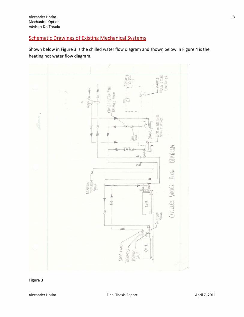
atic Drawin
elow in Figuhot water flo
ngs of Exist
re 3 is the cow diagram.
Final
ting Mecha
hilled water
l Thesis Report
anical Syste
r flow diagra
t
ems
m and showwn below in
April 7
Figure 4 is th
7, 2011
he
13

Alexander MechanicaAdvisor: D
Alexander
Figure 4
Hosko al Option r. Treado
Hosko Finall Thesis Reportt April 77, 2011
14

Alexander Hosko 15 Mechanical Option Advisor: Dr. Treado
Alexander Hosko Final Thesis Report April 7, 2011
Summary of Major Equipment
The Army Reserve Center contains three air handling units which are summarized in Table 1 below.
Table 1 The rest of the ventilation for several other spaces on the first floor is done using small unit ventilators. The unit ventilators are summarized in Table 2 below.
Table 2 To heat the Army Reserve Center, two boilers are present. They are summarized in Table 3 below.
Table 3 To cool the Army Reserve Center, two air‐cooled rotary screw packaged water chillers piped in parallel are used in the building. The chillers are manufactured by Trane, and they are summarized in Table 4 below.
TAG UNIT TYPE AREA SERVED MAX SA (CFM) MIN SA (CFM) MIN OA (CFM)AHU‐1 VAV FIRST FLOOR OFFICE 3700 1915 900AHU‐2 VAV SECOND FLOOR 13200 8175 2375AHU‐3 CV ASSEMBLY AREA 2100 2100 1345
AIR HANDLING UNIT SCHEDULE
CHILLED WATER COOLING COIL HOT WATER HEATING COILCAPACITY (MBH) TOT/SENS CAPACITY (MBH)
UV‐1 127‐CLASSROOM 625 155 12.9 / 12.1 27UV‐2 128‐CLASSROOM 440 150 20.4 / 13.3 14.4UV‐3 129‐CLASSROOM 440 150 20.4 / 13.3 14.4UV‐4 SOUTH SUPPLY OFFICES 606 95 17.8 / 17.01 19.9UV‐5 WEST SUPPLY OFFICES 650 95 25.1 / 23.4 21.2UV‐6 WEAPONS SIMULATOR 975 205 26.2 / 26.2 25.5UV‐7 SIPRNET CAFÉ 1575 85 25.5 / 24.9 58.1UV‐8 MAILROOM SUITE 375 50 12.9 / 9.4 10
FOUR PIPE UNIT VENTILATOR SCHEDULE
TAG AREA SERVED SUPPLY CFM MIN OA CFM
TAG TYPE MAX INPUT (MBH) MAX OUTPUT (MBH) MIN GAS INPUT (MBH)B ‐ 1,2 MODULATING VERTICAL 999 959 50
HOT WATER BOILER SCHEDULE

Alexander Hosko 16 Mechanical Option Advisor: Dr. Treado
Alexander Hosko Final Thesis Report April 7, 2011
Table 4
Pumps are used in the Army Reserve Center to send chilled and hot water throughout the building. They are summarized in Table 5 below.
Table 5
Lost Space Due to Mechanical System
There are three mechanical rooms in the Army Reserve Center. The mechanical room on the first floor contains the boilers, one mechanical room on the second floor contains AHU‐3, and the other mechanical room on the second floor contains AHU‐1 and AHU‐2. Shown below in Table 6 is the total area taken up by the mechanical rooms and the mechanical shaft area and the percentage of area compared to that of the total building area (the total building area is approximately 59,000 square feet).
Floor Area Percentage of Total Building Area 1st 1288 2.18% 2nd 1085 1.84% Total 2373 4.02%
Table 6
FULL LOAD EER FULL LOAD COP TYPE REFRIG. TYPE VOLTS/PHASE/HERTZ MCA MOCPCH‐1 40 9.9 2.9 SCROLL R‐410A 460 / 3 / 60 91.8 110.00CH‐2 52 9.9 2.9 SCROLL R‐410A 460 / 3 /60 108.2 125.00
EFFICIENCY COMPRESSORAIR COOLED CHILLER SCHEDULE
TAG NOMINAL CAPACITY (TONS)ELECTRICAL DATA
MOTOR HP NOMINAL MOTOR RPM VOLTS/PHASE/HERTZCHWP ‐ 1,2 BASE MTD, END SUCTION WATER 42 130 50 5 1750 480 / 3 /60HWP ‐ 1,2 INLINE BOOSTER WATER 130 100 10 3 / 4 1150 460 / 3 /60HWP ‐ 3,4 BASE MTD, END SUCTION WATER 130 100 55 5 1750 460 / 3 /60
TAG
PUMP SCHEDULEELECTRICAL DATA
HEAT (FT H2O)GPMFLUID TEMP (°F)FLUID TYPEPUMP TYPE
Alexander Hosko 17 Mechanical Option Advisor: Dr. Treado
Alexander Hosko Final Thesis Report April 7, 2011
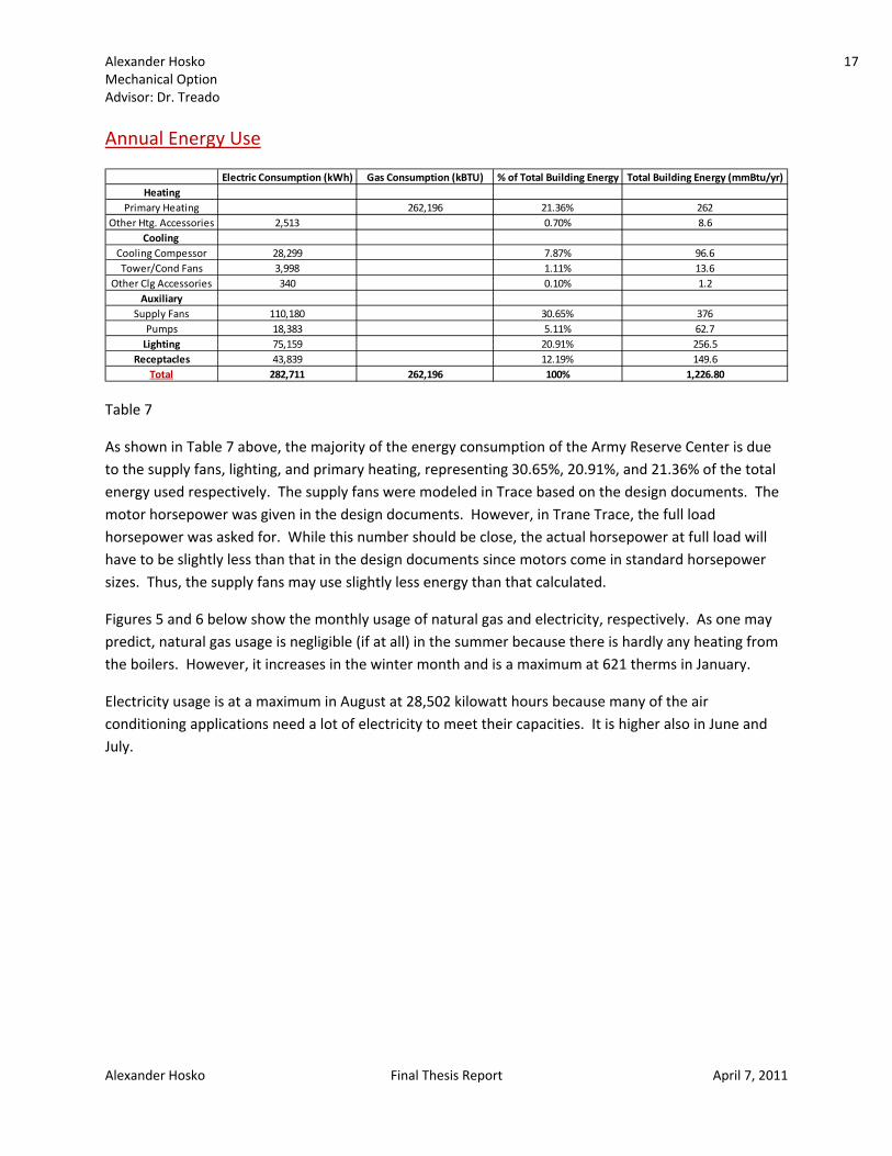
Annual Energy Use
Table 7
As shown in Table 7 above, the majority of the energy consumption of the Army Reserve Center is due to the supply fans, lighting, and primary heating, representing 30.65%, 20.91%, and 21.36% of the total energy used respectively. The supply fans were modeled in Trace based on the design documents. The motor horsepower was given in the design documents. However, in Trane Trace, the full load horsepower was asked for. While this number should be close, the actual horsepower at full load will have to be slightly less than that in the design documents since motors come in standard horsepower sizes. Thus, the supply fans may use slightly less energy than that calculated.
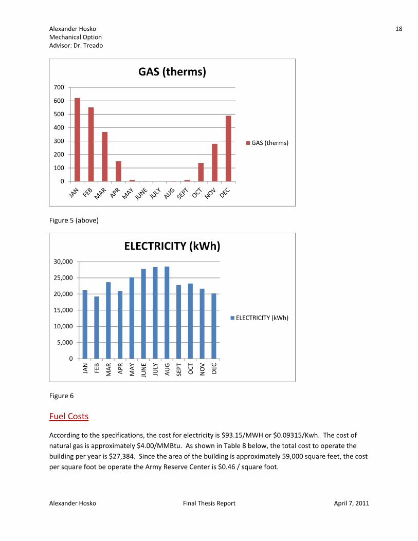
Figures 5 and 6 below show the monthly usage of natural gas and electricity, respectively. As one may predict, natural gas usage is negligible (if at all) in the summer because there is hardly any heating from the boilers. However, it increases in the winter month and is a maximum at 621 therms in January.
Electricity usage is at a maximum in August at 28,502 kilowatt hours because many of the air conditioning applications need a lot of electricity to meet their capacities. It is higher also in June and July.
Electric Consumption (kWh) Gas Consumption (kBTU) % of Total Building Energy Total Building Energy (mmBtu/yr)Heating
Primary Heating 262,196 21.36% 262Other Htg. Accessories 2,513 0.70% 8.6
Cooling Cooling Compessor 28,299 7.87% 96.6Tower/Cond Fans 3,998 1.11% 13.6
Other Clg Accessories 340 0.10% 1.2Auxiliary
Supply Fans 110,180 30.65% 376Pumps 18,383 5.11% 62.7Lighting 75,159 20.91% 256.5
Receptacles 43,839 12.19% 149.6Total 282,711 262,196 100% 1,226.80
Alexander Hosko 18 Mechanical Option Advisor: Dr. Treado
Alexander Hosko Final Thesis Report April 7, 2011
Figure 5 (above)
Figure 6 Fuel Costs
According to the specifications, the cost for electricity is $93.15/MWH or $0.09315/Kwh. The cost of natural gas is approximately $4.00/MMBtu. As shown in Table 8 below, the total cost to operate the building per year is $27,384. Since the area of the building is approximately 59,000 square feet, the cost per square foot be operate the Army Reserve Center is $0.46 / square foot.
0
100
200
300
400
500
600
700
GAS (therms)
GAS (therms)
0
5,000
10,000
15,000
20,000
25,000
30,000
JAN
FEB
MAR APR
MAY
JUNE
JULY
AUG
SEPT
OCT
NOV
DEC
ELECTRICITY (kWh)
ELECTRICITY (kWh)

Alexander Hosko 19 Mechanical Option Advisor: Dr. Treado
Alexander Hosko Final Thesis Report April 7, 2011
Table 8
Total Cost
As shown in Table 9 below, the total cost to obtain and install the air handling units, ductwork, unit ventilators, boilers, and chillers for the existing variable air volume system is $301,410. This was estimated using RS Means Cost Estimator.
Table 9
Electric Cost Gas Cost % of Total Building Cost Total Building CostHeating
Primary Heating $1,048.78 3.83% $1,048.78Other Htg. Accessories $234.09 0.85% $234.09
Cooling Cooling Compessor $2,636.05 9.63% $2,636.05Tower/Cond Fans $372.41 1.36% $372.41
Other Clg Accessories $31.67 0.12% $31.67Auxiliary
Supply Fans $10,263.27 37.48% $10,263.27Pumps $1,712.38 6.25% $1,712.38Lighting $7,001.06 25.57% $7,001.06
Receptacles $4,083.60 14.91% $4,083.60Total $26,334.53 $1,048.78 100% $27,383.31
Total Cost of Energy
VAV AREA SERVED CFM (MAX)HEATING
CAPACITY (MBH)COOLING CAPACITY (Total /
Sensible) (MBH)MANUFACTURER MODEL COST
AHU‐1 FIRST FLOOR OFFICES 3700 59.8 180 / 124 TRANE MCC $7,950.00AHU‐2 SECOND FLOOR 13200 144 530 / 380 TRANE MCC $21,775.00AHU‐3 ASSEMBLY 2100 125 148 / 81 TRANE MCC $5,055.00UV‐1 CLASSROOM 625 27 12.9 / 12.1 TRANE BCHC $2,125.00UV‐2 CLASSROOM 440 14.4 20.4 / 13.3 TRANE BCHC $2,335.00UV‐3 CLASSROOM 440 14.4 20.4 / 13.3 TRANE BCHC $2,335.00UV‐4 SOUTH SUPPLY OFFICES 606 19.9 17.8 / 17.0 TRANE BCHC $2,125.00UV‐5 WEST SUPPLY OFFICES 650 21.2 25.1 / 23.4 TRANE BCHC $2,705.00UV‐6 WEAPONS SIMULATOR 975 25.5 26.2 / 26.2 TRANE BCHC $2,705.00B‐1 WHOLE BUILDING ‐ 999 ‐ AERCO KC‐1000 $18,434.00B‐2 WHOLE BUILDING ‐ 999 ‐ AERCO KC‐1000 $18,434.00CH‐1 WHOLE BUILDING ‐ ‐ 480 TRANE CGAM040 $39,100.00CH‐2 WHOLE BUILDING ‐ ‐ 624 TRANE CGAM052 $44,625.00
DUCTWORK WHOLE BUILDING ‐ ‐ ‐ ‐ ‐ $131,707.00TOTAL COST $301,410.00

Alexander Hosko 20 Mechanical Option Advisor: Dr. Treado
Alexander Hosko Final Thesis Report April 7, 2011
ASHRAE Standard 62.1 Analysis
Table 10 As shown in Table 10 above, the Army Reserve Center is compliant with almost all of Section 5 and all of Section 6 of ASHRAE 62.1. Each occupant should receive enough ventilation air. The Army Reserve Center should not experience problems with mold or water leakage and the air quality also seems to be okay. The only exception occurs in Section 5.6 – Outdoor Air Intakes. It requires that outdoor air intakes are at least 15 feet from significantly contaminated exhaust. Several windows are about five to ten feet below an exhaust louver that runs out of room 123, a mechanical room. The exhaust comes from the janitor’s closet and toilet rooms and thus probably has an offensive odor, making it significantly contaminated. The rest of the outdoor air intakes meet the required separation distances.
SECTION COMPLIES?5.1 ‐ NATURAL VENTILATION YES
5.2 ‐ VENTILATION AIR DISTRIBUTION YES5.3 ‐ EXHAUST DUCT LOCATION YES
5.4 ‐ VENTILATION SYSTEM CONTROLS YES5.5 ‐ AIRSTREAM SURFACES YES5.6 ‐ OUTDOOR AIR INTAKES NO
5.7 ‐ LOCAL CAPTURE OF CONTAMINANTS YES5.8 ‐ COMBUSTION AIR YES
5.9 ‐ PARITCULATE MATTER REMOVAL YES5.10 ‐ DEHUMIDFICATION SYSTEMS YES
5.11 ‐ DRAIN PANS YES5.12 ‐ FINNED‐TUBE COILS AND HEAT EXCHANGERS YES5.13 ‐ HUMIDFIERS AND WATER‐SPRAY SYSTEMS YES
5.14 ‐ ACCESS FOR INSPECTION, CLEANING, AND MAINTENANCE YES5.15 ‐ BUILDING ENVELOPE AND INTERIOR SURFACES YES5.16 ‐ BUILDINGS WITH ATTACHED PARKING GARAGES YES
5.17 ‐ AIR CLASSIFICATION AND RECIRCULATION YES5.18 ‐ REQUIREMENTS FOR BUILDINGS CONTAINING ETS AREAS AND ETS FREE AREAS YES
6 ‐ VENTILATION RATE PROCEDURE YES
ASHRAE STANDARD 62.1 ANALYSIS

Alexander Hosko 21 Mechanical Option Advisor: Dr. Treado
Alexander Hosko Final Thesis Report April 7, 2011
ASHRAE Standard 90.1 Analysis
Table 11 As shown in Table 11 above, the Army Reserve Center is compliant with much of ASHRAE 90.1. The Army Reserve Center is entirely compliant and has even exceeded the requirements for Section 5.5, Perspective Building Envelope Option. This is due to caulking and sealing the joints of windows, doors, and louvers in order to limit infiltration. Also, the R‐values of the building materials exceed those required. However, the Army Reserve Center does not comply with Section 6, Heating, Ventilation, and Air Conditioning. It exceeds the maximum horsepower required for fans in Section 6.5. The Army Reserve Center does not follow Sections 7, Service Water Heating, and Section 8, Power, either. The water supplied to fixtures is ten degrees hotter than that required in Section 7 and the maximum voltage drop in branch circuits required is 10% versus the 2% allowed in Section 8. However, the Army Reserve Center not only meets, but exceeds all the requirements of Section 9, Lighting.
Although the Army Reserve Center fell short in meeting several requirements of ASHRAE 90.1, it still met most all of the requirements. The several that were not met may still be met after construction. For example, the maximum voltage drop in branch circuits may be less than 2% even though less than 10% was specified
Existing Mechanical Systems Conclusion
The mechanical systems for the Army Reserve Center seem to suit the building well. The Army Reserve Center is architecturally designed with three core spaces which are the auditorium, the western area of the first floor, and the second floor. Storage areas and smaller spaces,
SECTION COMPLIES? 5.1.4 ‐ CLIMATE YES
5.2 ‐ COMPLIANCE PATHS YES5.4 ‐ MANDATORY PROVISIONS YES
5.4.3.5 ‐ VESTIBULES YES5.5 ‐ PERSPECTIVE BUILDING ENVELOPE OPTION YES
6.3 ‐ SIMPLIFIED APPROACH OPTIONS FOR HVAC SYSTEMS YES6.4 ‐ MANDATORY PROVISIONS YES
6.5 ‐ PRESCRIPTIVE PATH NO7 ‐ SERVICE WATER HEATING NO
8 ‐ POWER NO9 ‐ LIGHTING YES
ASHRAE STANDARD 90.1 ANALYSIS

Alexander Hosko 22 Mechanical Option Advisor: Dr. Treado
Alexander Hosko Final Thesis Report April 7, 2011
conditioned by unit ventilators, compose the rest of the building. Although there are several distinct HVAC systems, the Army Reserve Center seems to be conditioned well.
One problem with the current design of the Army Reserve Center is the small ceiling to floor height between the first and second floor. This leads to ducts with aspect ratios that are higher than recommended. To fix this, a variable refrigerant flow system could have been installed to handle the heating and cooling loads, with smaller ducts in place to supply the required outside air to each space. This would lead to either smaller ducts with lower aspect ratios or a smaller height of the building, which may reduce the total cost.
The total cost to operate the Army Reserve Center is $27,384 per year or $0.46 / square foot. This was based on an estimate performed using Trane Trace 700.
The systems, although there are several, should be maintainable by a maintenance staff. They offer good environmental control and comply with ASHRAE’s requirements for indoor air quality. As mentioned above, the Army Reserve Center does a good job using several systems in a cost effective way.

Alexander Hosko 23 Mechanical Option Advisor: Dr. Treado
Alexander Hosko Final Thesis Report April 7, 2011
Mechanical System Redesign After analyzing the Army Reserve Center’s current mechanical systems and talking to the design engineer, several options were considered in the redesign. The design engineer specifically mentioned that a variable refrigerant flow (VRF) system should be considered as an alternative to the current variable air volume (VAV) system. Variable Refrigerant Flow A variable refrigerant flow (VRF) system contains multiple indoor evaporators connected to a single condensing unit allowing heat to be transferred directly to the space by pipes containing the refrigerant located throughout the building. The pipes will be smaller than the ducts of a variable air volume (VAV) system because the heat capacity of the refrigerant is larger than that of air. This handles all of the sensible loads for the building. However, either operable windows or a separate air handler must be used for ventilation and to meet the latent load. A variable refrigerant flow system has several benefits. VRF systems are lightweight, easily transported, and can fit into an elevator. To maintain the same load, the pipes of a VRF system take up less space than ductwork. Variable refrigerant flow systems save energy when compared to conventional variable air volume systems. They have multiple compressors in each condensing unit which allows for wide capacity modulation and thus high part‐load efficiency. Heat recovery VRF systems, which transfer heat from interior spaces that require cooling to exterior spaces that require heating, can be used for buildings that have simultaneous heating and cooling. Ground Couple Heat Pump A heat pump either extracts heat from the outside during the winter to warm a space or sinks heat to the outside in the summer to cool a space. A ground couple heat pump will be used to take advantage of the relatively constant 50°F – 60°F temperature of the Earth below the frost line. Although the life of a ground couple heat pump is longer than other, ground couple heat pumps are more expensive because wells must be dug for piping. Dedicated Outdoor Air System A dedicated outdoor air system (DOAS) brings in excess outside air to meet the ventilation requirements as well as the space latent load. The outside latent load is taken care of by the presence of desiccants and/or cooling coils. It also meets some of the sensible load. Chilled beams (active or passive), a variable refrigerant flow system, or several other options could be

Alexander Hosko 24 Mechanical Option Advisor: Dr. Treado
Alexander Hosko Final Thesis Report April 7, 2011
used to meet the rest of the sensible load. Thus, for the Army Reserve Center, DOAS accompanied with both a VRF System and a GCHP will be explored. Breadth Topics Acoustical Breadth If a variable refrigerant flow system is used, the condensing units will be placed on the roof. The condensing units will make noise and an acoustical study will be done to determine if material is required to surround each of them to minimize the noise to an acceptable level. Structural Breadth If a variable refrigerant flow system is used, the condensing units will be placed on the roof. This may change the roof’s structural requirements. A study will be done to determine the new roof deck, joists, and girders required to support the increased load. Integration and Coordination The Army Reserve Center should become far more energy efficient by decoupling the loads and ventilation. This will be done through the installation of a variable refrigerant flow (VRF) system to handle the sensible load requirements with a dedicated outdoor air system (DOAS) to handle the ventilation requirements and latent load. A ground couple heat pump is another possible idea which would improve the building’s energy efficiency with DOAS to handle the ventilation requirements and latent load. The three systems (VAV, VRF/DOAS, and GCHP/DOAS) will be compared in order to determine the best system for the Army Reserve Center. There will probably be structural changes due to the addition of condensing units on the roof for the VRF system. Acoustically, there will be changes as well due to the addition of condensing units. There should be no other changes in the lighting, electrical, or architectural aspects of the building.
Alexander Hosko 25 Mechanical Option Advisor: Dr. Treado
Alexander Hosko Final Thesis Report April 7, 2011
Variable Refrigerant Flow (VRF) with Dedicated Outdoor Air (DOAS) A variable refrigerant flow (VRF) system was selected to replace the existing variable air volume system and the smaller unit ventilators scattered throughout the Army Reserve Center. To meet the ventilation air requirements and the latent load, a separate dedicated outside air system (DOAS) will be used. Although this type of system has many benefits as mentioned above, it is especially beneficial for the Army Reserve Center.
The aspect ratio of a duct is equivalent to its width divided by its height. The aspect ratio should be as close as one as possible because, as the aspect ratio increases, the pressure required to move air through the duct also increases. As the pressure loss increases, the size of the supply and return fans must also increase. Not only does this increase the initial cost of the fans, but the cost of the energy required to operate the fans also increases. Another disadvantage of a high aspect ratio is that ducts with higher aspect ratios are noisier than their square counterparts.
The Army Reserve Center contains ducts on the first floor that have dimensions of 20x8, 30x6, and 60x8. This leads to aspect ratios of 2.5, 5, and 7.5, each of which is far too high. With a variable refrigerant flow system in place, the total amount of air supplied to each zone will decrease dramatically, and thus the duct size can be reduced.
Although several duct sizes on the first floor should be reduced, the ducts on the second floor have aspect ratios that are far more reasonable. Thus, by using a variable refrigerant flow system their sizes can be reduced and it would be possible to shrink the plenum reducing the overall size of the building. This would thus reduce the total project cost and construction time.
Another benefit of using a variable refrigerant flow system is that the boilers can be removed from the building and smaller chillers can be used for the dedicated outdoor air system. This reduces cost for several reasons. It eliminates the cost of the boilers and larger chillers themselves, but also reduces cost for associated equipment, such as pumps and piping for each boiler and chiller. The Army Reserve Center would also not have to connect to a natural gas line. However, the U.S. Army Corps of Engineers would probably still want to have the ability for natural gas if necessary.
A variable refrigerant flow system has a much higher efficiency than the conventional variable air volume system with chillers. The COP of the chillers used in the Army Reserve Center is 2.90 at full load. Shown in Figure 7 below is the COP for the Multi V Sync developed by Life’s Good Electronics. The Multi V Sync is a variable refrigerant flow system capable of simultaneous

Alexander MechanicaAdvisor: D
Alexander
heating arequiringto save e
Figure 7 Load An
Trane Traenergy relatent loa In the Trawas also dehumidThe air wcool air w
Hosko al Option r. Treado
Hosko
and cooling tg cooling andenergy. A dia
nalysis
ace 700 wasequired as wads was dete
ace model, aused. The d
dified to the was not rehewill help to t
to different d transferrinagram of thi
s used to mowell as the heermined usin
a Variable Rededicated velow dew poated becausake care of s
Final
zones. Heatng it to a zons system is s
odel the Armeating and cng a hand ca
efrigerant Voentilation sysint requiredse latent loasome of the
l Thesis Report
t recovery, de requiring shown in Fig
my Reserve Cooling loadsalculation.
olume Systestem was co in the desigd is a problesensible loa
t
done by takiheating andgure 8 below
Center in ords. The outsid
em was seleconfigured so gn documentem in coolingad.
ng energy fr vice versa, w.
der to determde air requir
cted. Dedica that it woults without bg and not he
April 7
rom a zone is also empl
Figure 8
mine the totred to meet
ated ventilatld be being reheateating. Thus
7, 2011
oyed
al the
tion
ed. s, this
26

Alexander Hosko 27 Mechanical Option Advisor: Dr. Treado
Alexander Hosko Final Thesis Report April 7, 2011
Airflow Airflow was determined by the design engineer using ASHRAE 62.1. The infiltration for the building was assumed to be pressurized tight construction thus allowing 0.3 air changes per hour. Lighting The average lighting of the Army Reserve Center is 0.71 Watts / square foot. Since the design load is estimated based on the block load method, this is used for each of the blocks. Schedules
The Army Reserve Center is primarily a low rise office building. Thus, the schedules that were used for the lighting, people, and ventilation were the low rise office schedules. They are shown for the typical weekday below in Tables 12, 13, 14, and 15 below.
Table 12 Table 13
Start Time End Time PercentageMidnight 7 a.m. 07 a.m. Midnight 100
Vent ‐ Low Rise Office
Start Time End Time PercentageMidnight 7 a.m. 07 a.m. 8 a.m. 308 a.m. 11 a.m. 10011 a.m. Noon 80Noon 1 p.m. 401 p.m. 2 p.m. 802 p.m. 5 p.m. 1005 p.m. 6 p.m. 306 p.m. 9 p.m. 109 p.m. Midnight 5
People ‐ Low Rise Office

Alexander Hosko 28 Mechanical Option Advisor: Dr. Treado
Alexander Hosko Final Thesis Report April 7, 2011
Table14 Table 15
Occupancy The number of people each space is to be designed for is given in the design documents. Those values are used to determine the occupancy. For the offices, each occupant is assumed to have a personal computer that gives off 150 watts. For the library and the copy center, an appropriate amount of watts for each computer, copier, and printer are assumed. Each person is assumed for most spaces to have a sensible load of 250 Btu/h and a latent load of 200 Btu/h because most of the spaces are classrooms or general office space. However, each person is assumed to have a sensible load of 225 Btu/h and a latent load of 105 Btu/h for the auditorium. Indoor / Outdoor Air Conditions
The design conditions of Providence, Rhode Island were used for the Army Reserve Center because they were the closet available to Newport, Rhode Island. These are: Heating: 10.8°F (99.0% Occurrence) Cooling: 89.7°F DB / 73.2°F WB (0.4% Occurrence) However, because it was requested by the US Army Corps of Engineers, 0°F was used for heating. Also, as requested, indoor cooling design conditions shall be 74°F with 50% relative humidity and indoor heating shall be 72°F for occupied spaces and 55°F for unoccupied spaces.
Start Time End Time PercentageMidnight 7 a.m. 57 a.m. 8 a.m. 808 a.m. 10 a.m. 9010 a.m. Noon 95Noon 2 p.m. 802 p.m. 4 p.m. 904 p.m. 5 p.m. 955 p.m. 6 p.m. 806 p.m. 7 p.m. 707 p.m. 8 p.m. 608 p.m. 9 p.m. 409 p.m. 10 p.m. 3010 p.m. Midnight 20
Misc ‐ Low Rise OfficeStart Time End Time PercentageMidnight 7 a.m. 57 a.m. 8 a.m. 808 a.m. 10 a.m. 9010 a.m. Noon 95Noon 2 p.m. 802 p.m. 4 p.m. 904 p.m. 5 p.m. 955 p.m. 6 p.m. 806 p.m. 7 p.m. 707 p.m. 8 p.m. 608 p.m. 9 p.m. 409 p.m. 10 p.m. 3010 p.m. Midnight 20
Lights ‐ Low Rise Office
Alexander Hosko 29 Mechanical Option Advisor: Dr. Treado
Alexander Hosko Final Thesis Report April 7, 2011
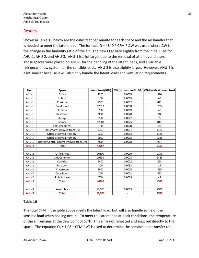
Results
Shown in Table 16 below are the cubic feet per minute for each space and the air handler that is needed to meet the latent load. The formula Q = 4840 * CFM * ∆W was used where ∆W is the change in the humidity ratio of the air. The new CFM vary slightly from the initial CFM for AHU‐1, AHU‐2, and AHU‐3. AHU‐1 is a lot larger due to the removal of all unit ventilators. Those spaces were placed on AHU‐1 for the handling of the latent loads, and a variable refrigerant flow system for the sensible loads. AHU‐3 is also slightly larger. However, AHU‐2 is a lot smaller because it will also only handle the latent loads and ventilation requirements.
Table 16
The total CFM in the table above meets the latent load, but will also handle some of the sensible load when cooling occurs. To meet the latent load at peak conditions, the temperature of the air remains at the dew point of 57°F. This air is not reheated and supplied directly to the space. The equation Qs = 1.08 * CFM * ∆T is used to determine the sensible heat transfer rate
Unit Space Latent Load (BTU) ∆W (lb moisture/lb DA) CFM to Meet Latent LoadAHU‐1 Office 1200 0.0005 526AHU‐1 Lobby 100 0.0005 40AHU‐1 Corridor 2500 0.0012 441AHU‐1 Breakroom 12917 0.0038 705AHU‐1 Armory 200 0.0009 46AHU‐1 Restroom 900 0.0020 94AHU‐1 Storage 250 0.0007 75AHU‐1 Library 12000 0.0025 1009AHU‐1 Fam Readiness 100 0.0008 27AHU‐1 Classrooms (moved from UV) 7300 0.0011 1427AHU‐1 Offices (moved from UV) 2200 0.0004 1136AHU‐1 Offices (moved from UV) 3000 0.0002 3338AHU‐1 Interior Control Rooms (moved from UV) 900 0.0008 237AHU‐1 Total 43567 ‐ 9101
AHU‐2 Office Area 20800 0.0020 2149AHU‐2 Unit Common 19330 0.0028 1419AHU‐2 Corridor 2400 0.0022 223AHU‐2 Restroom 300 0.0033 19AHU‐2 Classroom 2600 0.0015 365AHU‐2 Copy Room 200 0.0001 362AHU‐2 Pub Storage 700 0.0029 49AHU‐2 Total 46330 4585
AHU‐3 Assembly 18,900 0.0013 2936AHU‐3 Total 18,900 ‐ 2936

Alexander Hosko 30 Mechanical Option Advisor: Dr. Treado
Alexander Hosko Final Thesis Report April 7, 2011
that can be met with the CFM used to handle the latent load. This is shown for each space in Table 17 below when the space is in cooling mode.
Table 17
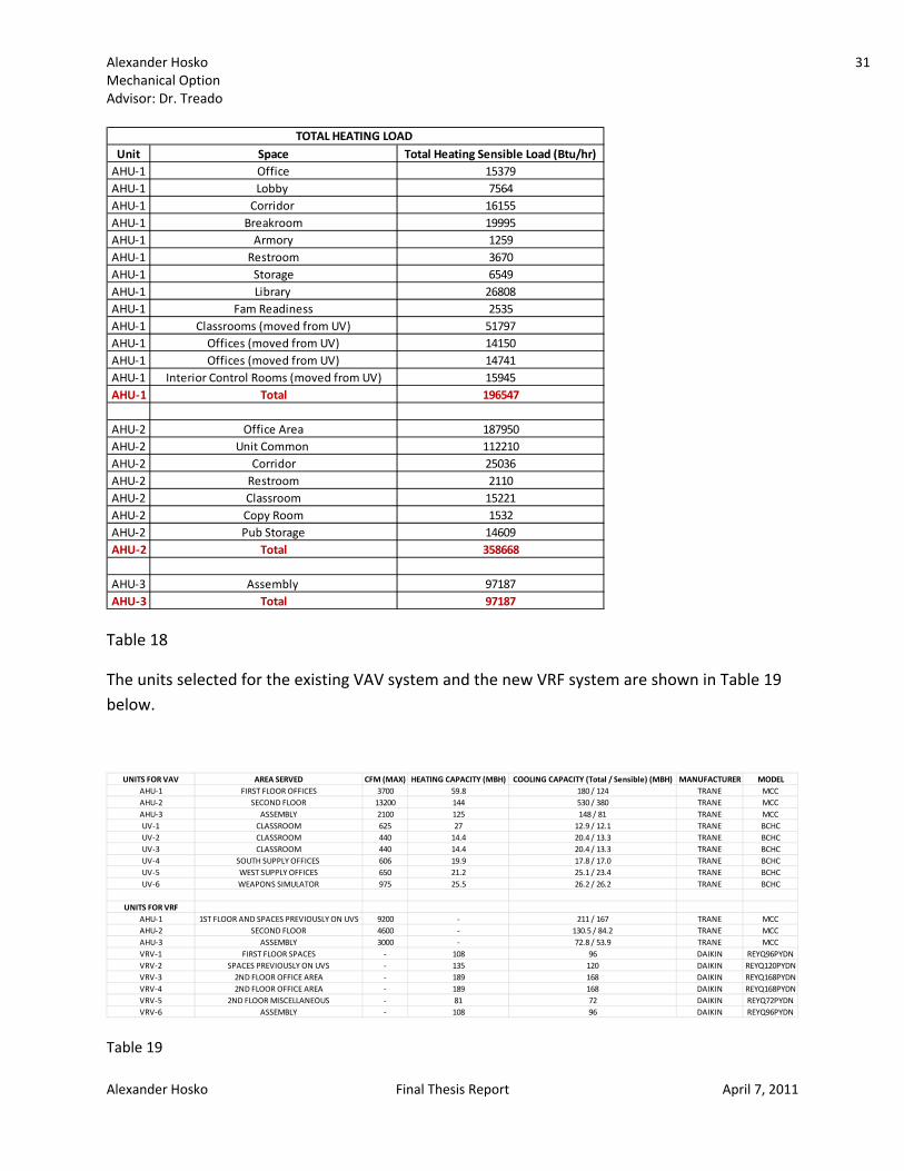
In heating mode, the CFM of air supplied will only be heated up to room temperature. Thus, the remaining loads must be met through the variable refrigerant flow system. When modeling in Trace, these loads will include everything except for the ventilation loads. The total heating loads are shown in the Table 18 below.
Unit Space CFM from latent load ∆T (°F) Sensible Load Met by CFM (Btu/hr) Total Cooling Sensible Load (Btu/hr) Remaining Cooling Sensible Load (Btu/hr)AHU‐1 Office 526 17 9665 22200 12535AHU‐1 Lobby 40 17 738 3300 2562AHU‐1 Corridor 441 17 8096 9300 1204AHU‐1 Breakroom 705 17 12943 22200 9257AHU‐1 Armory 46 17 843 1500 657AHU‐1 Restroom 94 17 1732 3300 1568AHU‐1 Storage 75 17 1383 3700 2317AHU‐1 Library 1009 17 18526 27700 9174AHU‐1 Fam Readiness 27 17 492 2300 1808AHU‐1 Classrooms (moved from UV) 1427 17 26195 47800 21605AHU‐1 Offices (moved from UV) 1136 17 20864 24900 4036AHU‐1 Offices (moved from UV) 3338 17 61278 23900 0AHU‐1 Interior Control Rooms (moved from UV) 237 17 4345 12500 8155AHU‐1 Total 9101 ‐ 167098 204600 74880
AHU‐2 Office Area 2149 17 39451 271900 232449AHU‐2 Unit Common 1419 17 26055 126600 100545AHU‐2 Corridor 223 17 4085 29200 25115AHU‐2 Restroom 19 17 348 3900 3552AHU‐2 Classroom 365 17 6703 14500 7797AHU‐2 Copy Room 362 17 6638 2800 0AHU‐2 Pub Storage 49 17 907 13500 12593AHU‐2 Total 4585 ‐ 84187 462400 382051
AHU‐3 Assembly 2936 17 53906 95500 41594AHU‐3 Total 2936 ‐ 53906 95500 41594
Sensible Load Met by CFM from Latent Load for Cooling
Alexander Hosko 31 Mechanical Option Advisor: Dr. Treado
Alexander Hosko Final Thesis Report April 7, 2011
Table 18
The units selected for the existing VAV system and the new VRF system are shown in Table 19 below.
Table 19
Unit Space Total Heating Sensible Load (Btu/hr)AHU‐1 Office 15379AHU‐1 Lobby 7564AHU‐1 Corridor 16155AHU‐1 Breakroom 19995AHU‐1 Armory 1259AHU‐1 Restroom 3670AHU‐1 Storage 6549AHU‐1 Library 26808AHU‐1 Fam Readiness 2535AHU‐1 Classrooms (moved from UV) 51797AHU‐1 Offices (moved from UV) 14150AHU‐1 Offices (moved from UV) 14741AHU‐1 Interior Control Rooms (moved from UV) 15945AHU‐1 Total 196547
AHU‐2 Office Area 187950AHU‐2 Unit Common 112210AHU‐2 Corridor 25036AHU‐2 Restroom 2110AHU‐2 Classroom 15221AHU‐2 Copy Room 1532AHU‐2 Pub Storage 14609AHU‐2 Total 358668
AHU‐3 Assembly 97187AHU‐3 Total 97187
TOTAL HEATING LOAD
UNITS FOR VAV AREA SERVED CFM (MAX) HEATING CAPACITY (MBH) COOLING CAPACITY (Total / Sensible) (MBH) MANUFACTURER MODELAHU‐1 FIRST FLOOR OFFICES 3700 59.8 180 / 124 TRANE MCCAHU‐2 SECOND FLOOR 13200 144 530 / 380 TRANE MCCAHU‐3 ASSEMBLY 2100 125 148 / 81 TRANE MCCUV‐1 CLASSROOM 625 27 12.9 / 12.1 TRANE BCHCUV‐2 CLASSROOM 440 14.4 20.4 / 13.3 TRANE BCHCUV‐3 CLASSROOM 440 14.4 20.4 / 13.3 TRANE BCHCUV‐4 SOUTH SUPPLY OFFICES 606 19.9 17.8 / 17.0 TRANE BCHCUV‐5 WEST SUPPLY OFFICES 650 21.2 25.1 / 23.4 TRANE BCHCUV‐6 WEAPONS SIMULATOR 975 25.5 26.2 / 26.2 TRANE BCHC
UNITS FOR VRFAHU‐1 1ST FLOOR AND SPACES PREVIOUSLY ON UVS 9200 ‐ 211 / 167 TRANE MCCAHU‐2 SECOND FLOOR 4600 ‐ 130.5 / 84.2 TRANE MCCAHU‐3 ASSEMBLY 3000 ‐ 72.8 / 53.9 TRANE MCCVRV‐1 FIRST FLOOR SPACES ‐ 108 96 DAIKIN REYQ96PYDNVRV‐2 SPACES PREVIOUSLY ON UVS ‐ 135 120 DAIKIN REYQ120PYDNVRV‐3 2ND FLOOR OFFICE AREA ‐ 189 168 DAIKIN REYQ168PYDNVRV‐4 2ND FLOOR OFFICE AREA ‐ 189 168 DAIKIN REYQ168PYDNVRV‐5 2ND FLOOR MISCELLANEOUS ‐ 81 72 DAIKIN REYQ72PYDNVRV‐6 ASSEMBLY ‐ 108 96 DAIKIN REYQ96PYDN

Alexander Hosko 32 Mechanical Option Advisor: Dr. Treado
Alexander Hosko Final Thesis Report April 7, 2011
Annual Energy Use
Table 20
As shown in the Table 20 above, the total building energy consumed by the Army Reserve Center is 1,018 mmBtu/yr. All of the energy used by the building is electricity which would thus allow the natural gas connections to the building to be eliminated. However, in case of power failure or if the army wants a backup natural gas boiler, they should probably still be left in. The main sources of energy use are primary heating and lighting. They use 30.49% and 24.97% of the electricity respectively. Figure below shows the monthly use of electricity. The total electricity usage for the Army Reserve Center is 298,269 kWh for a whole year. The electricity is a maximum in January at 34,078 kWh. This is because, unlike the existing VAV system, electricity is used for both heating and cooling and no natural gas is present. As shown in figure below, the electricity usage is maximum in the winter and summer, when mostly heating or cooling is required. This is because, as shown in Figure 7, the COP of a VRF system is maximum whenever the load requires about half heating and half cooling because of heat recovery.
Figure 9
Electric Consumption (kWh) Gas Consumption (kBTU) % of Total Building Energy Total Building Energy (mmBtu/yr)Heating
Primary Heating 90,935 30.49% 310.4Other Htg. Accessories 0.00%
Cooling Cooling Compessor 35,409 11.88% 120.9Tower/Cond Fans 4,693 1.57% 16
Other Clg Accessories 296 0.10% 1Auxiliary
Supply Fans 45,602 15.28% 155.6Pumps 2,029 0.68% 6.9Lighting 74,484 24.97% 254.2
Receptacles 44,821 15.03% 153Total 298,269 ‐ 100% 1,018.00
05,000
10,00015,00020,00025,00030,00035,00040,000
JAN
FEB
MAR APR
MAY
JUNE
JULY
AUG
SEPT
OCT
NOV
DEC
ELECTRICITY (kWh)
ELECTRICITY (kWh)

Alexander Hosko 33 Mechanical Option Advisor: Dr. Treado
Alexander Hosko Final Thesis Report April 7, 2011
Fuel Costs
According to the specifications, the cost for electricity is $93.15/MWH or $0.09315/Kwh. The cost of natural gas is approximately $4.00/MMBtu. However, using a VRF system, there is no natural gas used in the Army Reserve Center. As shown in the Table 21 below, the total annual energy cost to operate the building is $27,783.76.
Table 21
Total Cost
As shown in Table 22 below, the total cost to obtain and install the variable refrigerant volume units and the air handling units for the variable volume system is $283,105. This was found online from manufacturer catalogs (where available) and using RS Means Costworks.
Table 22
Electric Cost Gas Cost % of Total Building Cost Total Building CostHeating
Primary HeatingOther Htg. Accessories $8,470.60 30.49% $8,470.60
Cooling Cooling Compessor $3,298.35 11.87% $3,298.35Tower/Cond Fans $437.15 1.57% $437.15
Other Clg Accessories $27.57 0.10% $27.57Auxiliary
Supply Fans $4,247.83 15.29% $4,247.83Pumps $189.00 0.68% $189.00Lighting $6,938.18 24.97% $6,938.18
Receptacles $4,175.08 15.03% $4,175.08Total $27,783.76 ‐ 100% $27,783.76
Total Cost of Energy
VRF AREA SERVED CFM (MAX)HEATING
CAPACITY (MBH)COOLING CAPACITY (Total /
Sensible) (MBH)MANUFACTURER MODEL COST
AHU‐1 1ST FLOOR AND SPACES PREVIOUSLY ON UVS 9200 ‐ 211 / 167 TRANE MCC $17,250.00AHU‐2 SECOND FLOOR 4600 ‐ 130.5 / 84.2 TRANE MCC $9,725.00AHU‐3 ASSEMBLY 3000 ‐ 72.8 / 53.9 TRANE MCC $6,200.00CH‐1 AHUs FOR DEHUMIDFICATION ‐ ‐ 96 TTRANE CGAM040 $10,900.00VRV‐1 FIRST FLOOR SPACES ‐ 108 96 DAIKIN REYQ96PYDN$15,459.84VRV‐2 SPACES PREVIOUSLY ON UVS ‐ 135 120 DAIKIN EYQ120PYD $21,642.24VRV‐3 2ND FLOOR OFFICE AREA ‐ 189 168 DAIKIN EYQ168PYD $29,372.16VRV‐4 2ND FLOOR OFFICE AREA ‐ 189 168 DAIKIN EYQ168PYD $29,372.16VRV‐5 2ND FLOOR MISCELLANEOUS ‐ 81 72 DAIKIN REYQ72PYDN$12,480.00VRV‐6 ASSEMBLY ‐ 108 96 DAIKIN REYQ96PYDN$15,459.84
DUCTWORK WHOLE BUILDING ‐ ‐ ‐ ‐ ‐ $115,243.00TOTAL COST $283,104.24
Alexander Hosko 34 Mechanical Option Advisor: Dr. Treado
Alexander Hosko Final Thesis Report April 7, 2011
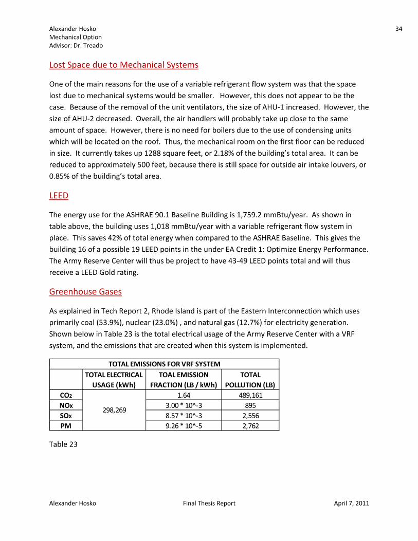
Lost Space due to Mechanical Systems
One of the main reasons for the use of a variable refrigerant flow system was that the space lost due to mechanical systems would be smaller. However, this does not appear to be the case. Because of the removal of the unit ventilators, the size of AHU‐1 increased. However, the size of AHU‐2 decreased. Overall, the air handlers will probably take up close to the same amount of space. However, there is no need for boilers due to the use of condensing units which will be located on the roof. Thus, the mechanical room on the first floor can be reduced in size. It currently takes up 1288 square feet, or 2.18% of the building’s total area. It can be reduced to approximately 500 feet, because there is still space for outside air intake louvers, or 0.85% of the building’s total area.
LEED
The energy use for the ASHRAE 90.1 Baseline Building is 1,759.2 mmBtu/year. As shown in table above, the building uses 1,018 mmBtu/year with a variable refrigerant flow system in place. This saves 42% of total energy when compared to the ASHRAE Baseline. This gives the building 16 of a possible 19 LEED points in the under EA Credit 1: Optimize Energy Performance. The Army Reserve Center will thus be project to have 43‐49 LEED points total and will thus receive a LEED Gold rating.
Greenhouse Gases
As explained in Tech Report 2, Rhode Island is part of the Eastern Interconnection which uses primarily coal (53.9%), nuclear (23.0%) , and natural gas (12.7%) for electricity generation. Shown below in Table 23 is the total electrical usage of the Army Reserve Center with a VRF system, and the emissions that are created when this system is implemented.
Table 23
TOTAL ELECTRICAL USAGE (kWh)
TOAL EMISSION FRACTION (LB / kWh)
TOTAL POLLUTION (LB)
CO2 1.64 489,161NOX 3.00 * 10^‐3 895SOX 8.57 * 10^‐3 2,556PM 9.26 * 10^‐5 2,762
298,269
TOTAL EMISSIONS FOR VRF SYSTEM

Alexander MechanicaAdvisor: D
Alexander
Groun
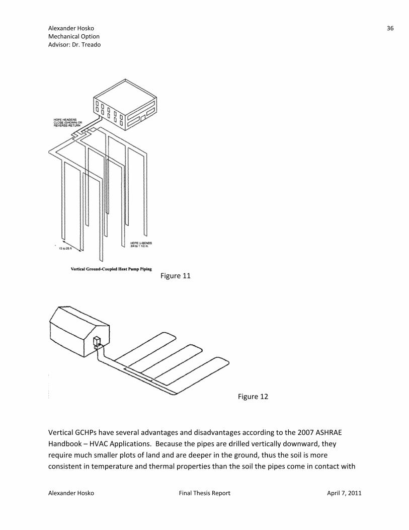
A groundto help tosource othe earthrefrigerashown in
The advadescribedoutdoor air handl
There arethose in wFigure 12
Hosko al Option r. Treado
Hosko
d Couple
d couple heao reduce enr sink, depenh has a relatint through pn Figure 10.
antages of usd above. Usair handlersers.
e two types which the p2, are those
Heat Pu
at pump (GCergy consumnding on whively constanpipes in the
sing a GCHP sing a GCHP s to replace t
of GCHPs: vipes are placin which pip
Final
mp (GCH
HP) and a demption. A grhether heatinnt temperatground and
are similar twill save enthe existing
ertical and hced downwapes are laid a
l Thesis Report
P) with D
edicated outround coupleng or coolingture of 50°F –then passin
to those of tergy and willarger variab
horizontal. Vard in to the across the gr
t
Dedicated
tdoor air syse heat pumpg is required– 60°F. A GCg it through
Figur
the variable ll also allow ble air volum
Vertical GCHground andround.
d Outdoo
stem (DOAS)p uses the Ead. This workCHP does th a heat exch
re 10
refrigerant ffor smaller
me and const
HPs, shown id horizontal
April 7
or Air (DO
) could be usarth as a heaks well becauhis by sendinhanger. This
flow systemdedicated tant air volu
n Figure 11, GCHPs, show
7, 2011
OAS)
sed at use ng a is
m
ume
are wn in
35
Alexander MechanicaAdvisor: D
Alexander
Vertical GHandboorequire mconsisten
Hosko al Option r. Treado
Hosko
GCHPs have ok – HVAC Amuch smallent in temper
several advapplications. r plots of lanrature and th
Final
Figure 11
antages and Because thnd and are dhermal prop
l Thesis Report
d disadvantae pipes are ddeeper in theperties than t
t
Figure 12
ges accordindrilled vertice ground, ththe soil the
2
ng to the 200cally downwhus the soil ispipes come
April 7
07 ASHRAE ward, they s more in contact w
7, 2011
with
36

Alexander Hosko 37 Mechanical Option Advisor: Dr. Treado
Alexander Hosko Final Thesis Report April 7, 2011
in a horizontal GCHP. Other advantages are that they require the smallest amount of piping and pumping energy and yield the most efficient GCHP system performance. Disadvantages include that it is difficult to find contractors able to install a vertical loop GCHP and the higher cost of installing a vertical loop GCHP.
Horizontal GCHPs also have several advantages and disadvantages according to the 2007 ASHRAE Handbook – HVAC Applications. The advantages are that they cost less than vertical GCHPs and trained equipment operators are more widely available. The disadvantages are that ground properties fluctuate because the pipes are not deep enough to be unaffected by season and rainfall, pumps need to use more energy, and the system is less efficient.
Load Analysis
Trane Trace 700 was used to model the Army Reserve Center in order to determine the total energy required as well as the heating and cooling loads. The outside air required to meet the latent loads was determined using a hand calculation.
In the Trace model, a water source heat pump (WSHP) is initially selected as the system type. However, when defining the cooling plant, a ground couple heat pump can be selected under the equipment type tab. As in the variable refrigerant volume system, dedicated ventilation is once again selected.
Assumptions Airflow, lighting, schedules, occupancy, indoor conditions, and outdoor conditions are all the same as those used for designing the variable refrigerant flow system.
Sizing the GCHP
Table 24
The heat pumps shown in Table 24 above will be used in order to meet the heating and cooling capacity of the building.
HEAT PUMP NO. OF UNITS MANUFACTURER MODEL CAPACITY (TONS)GSHP 1‐17 17 TRANE 4TWB3060A 5

Alexander MechanicaAdvisor: D
Alexander
Vertical
To size a treats thequation
Howeverexchangeand intermust thu
Hosko al Option r. Treado
Hosko
l
vertical groe design as hn is used:
r, this equatier by using arfaces betweus be used:
und couple heat transfe
ion must be a series of coeen the pipe
Final
heat pump, r from a cyli
modified toonstant heate and fluid an
l Thesis Report
the methodinder buried
o account fort‐rate pulsesnd the pipe a
t
d of Ingersolld within the e
r the variabls and also thand the grou
l and Zobel cearth. The f
e heat rate e resistanceund. The fo
April 7
can be used.following
of a ground e of the pipellowing equa
7, 2011
. It
heat wall ation
38

Alexander MechanicaAdvisor: D
Alexander
Fsc: Fsc iHVAC Apbe used.
Table 25
PLFm: Thethe total
qa: To deused:
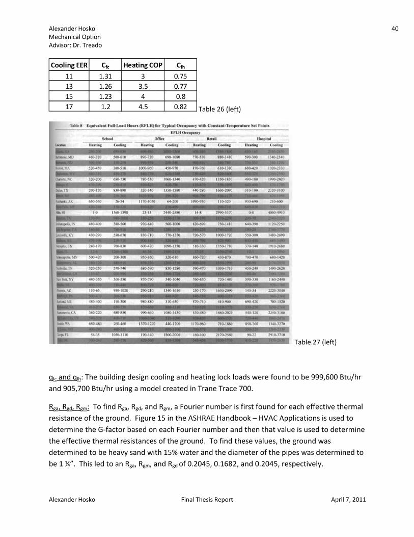
Cfc and Cheat pumhours whTable 27 heating aNewportheating bSince 8.5much), th999,600 228,894
Hosko al Option r. Treado
Hosko
s found usinpplications. T
e part load fcapacity ava
etermine the
fh are heat pmp shown inhich are provbelow. For are 970 and t, Rhode Islabecause an E50 is not in thhe heating CBtu/hr and aBtu/hr.
ng Table 25 bThree Bores
factor for theailable. This
e net annual
pump correc Table 26 bevided in the the Army Re1000, respend. The heaEER of 11.3 ihe Table 26 COP of 4.5 wa building de
Final
below whichs per Loop w
e design mos is equal to
average hea
tion factors elow, and EF2007 ASHRAeserve Centectively, becaat pump corrs used for co(and this is a
will be assumesign heatin
l Thesis Report
h is found in will be selecte
nth is found0.98 for the
at transfer to
based on thFLhoursc andAE Handbooer, the equivause Boston rection factoooling and foa maximum ed. With a bg block load
t
Chapter 32 ed at 3 gpm/
d by dividing Army Reser
o the ground
he cooling EEd EFLhoursh aok – HVAC Apvalent full lo was used siors are 1.302or heating, aCOP which ibuilding desd of 905,700
in the ASHR/ton thus a v
g the load of rve Center.
d, the follow
ER and heatiare the equipplications aoad hours foince it is the2 for coolinga COP of 8.5is probably nsign cooling bBtu/hr, qa w
April 7
AE Handboovalue of 1.01
the building
wing equatio
ing COP of thvalent full‐loand shown inr cooling an closest city g and 0.82 fo0 is presentnot achievedblock load owas found to
7, 2011
ok – 1 will
g by
on is
he oad n d to or . d of o be
39
Alexander MechanicaAdvisor: D
Alexander
qlc and qland 905,
Rga, Rgd, Rresistancdeterminthe effecdeterminbe 1 ¼”.
Cooling E11131517
Hosko al Option r. Treado
Hosko
lh: The build700 Btu/hr u
Rgm: To find ce of the grone the G‐factctive thermaned to be heThis led to a
EER Cfc1.311.261.231.2
ing design cousing a mod
Rga, Rgd, andund. Figuretor based onl resistanceseavy sand wian Rga, Rgm, a
Heating CO33.544.5
Final
ooling and hel created in
d Rgm, a Foure 15 in the ASn each Fouris of the grouth 15% wateand Rgd of 0.
OP Cfh0.750.770.80.82
l Thesis Report
Table 26 (le
heating lock n Trane Trac
rier number SHRAE Hander number aund. To finder and the d2045, 0.168
t
eft)
loads were fce 700.
is first foundbook – HVAand then tha these valueiameter of t2, and 0.204
Table
found to be
d for each eAC Applicatioat value is uses, the grounthe pipes wa45, respectiv
April 7
e 27 (left)
999,600 Btu
effective therons is used tsed to deternd was as determinevely.
7, 2011
u/hr
rmal to mine
ed to
40
Alexander MechanicaAdvisor: D
Alexander
Rb: Rb waApplicati
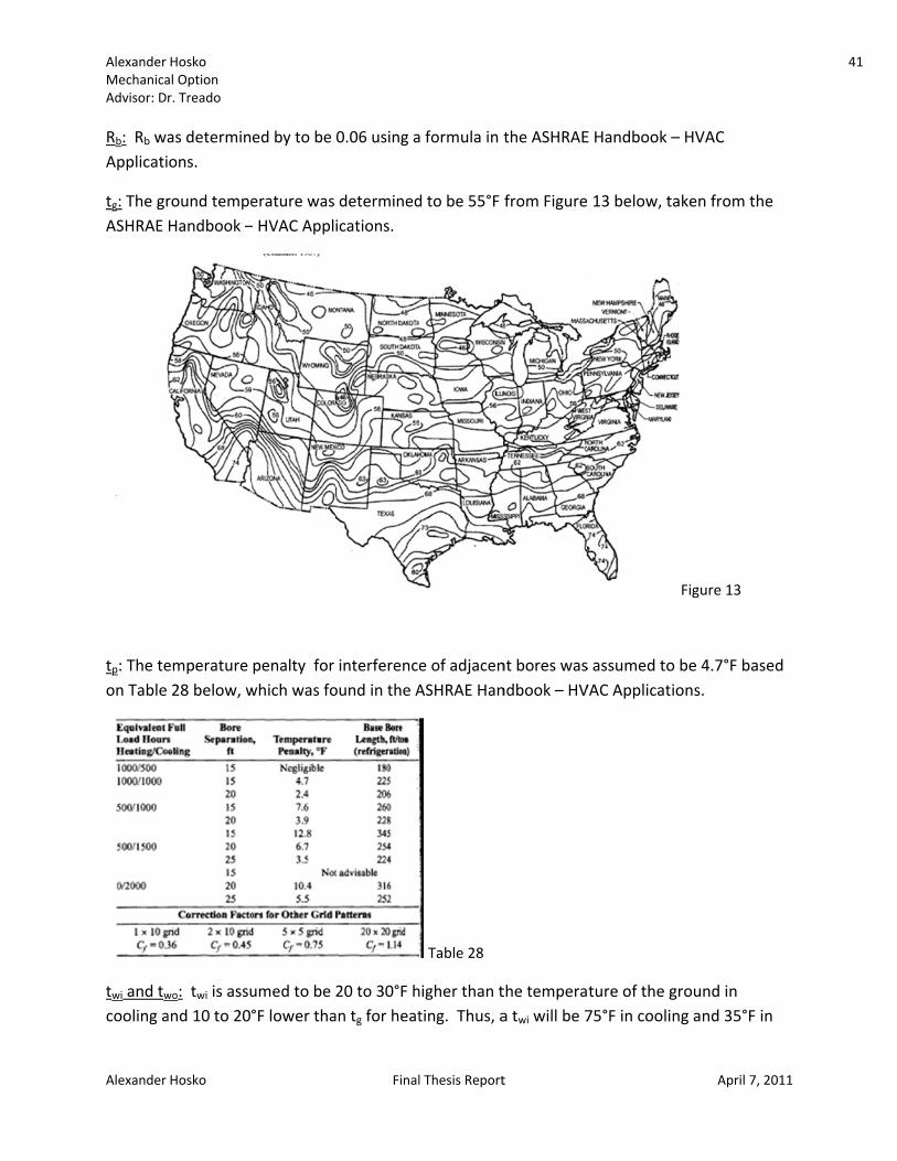
tg: The grASHRAE
tp: The teon Table
twi and twcooling a
Hosko al Option r. Treado
Hosko
as determinons.
round tempeHandbook –
emperature 28 below, w
wo: twi is assuand 10 to 20°
ed by to be
erature was – HVAC Appl
penalty for which was fo
umed to be °F lower tha
Final
0.06 using a
determinedications.
interferenceound in the A
20 to 30°F han tg for heat
l Thesis Report
a formula in t
d to be 55°F
e of adjacenASHRAE Han
Table 28
higher than tting. Thus, a
t
the ASHRAE
from Figure
nt bores wasndbook – HV
the temperaa twi will be 7
E Handbook –
13 below, t
s assumed toVAC Applicat
ture of the g75°F in cooli
April 7
– HVAC
taken from t
Figure 13
o be 4.7°F baions.
ground in ng and 35°F
7, 2011
he
ased
in
41
Alexander MechanicaAdvisor: D
Alexander
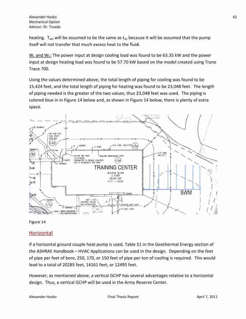
heating. itself will
Wc and Winput at dTrace 700
Using the15,424 feof pipingcolored bspace.
Figure 14
Horizon
If a horizthe ASHRof pipe plead to a
Howeverdesign. T
Hosko al Option r. Treado
Hosko
Two will be al not transfe
Wh: The powdesign heati0.
e values deteeet, and the g needed is tblue in in Fig
ntal
ontal groundRAE Handboper feet of bototal of 202
r, as mentionThus, a verti
assumed to r that much
wer input at dng load was
ermined abototal lengthhe greater ogure 14 below
d couple heaok – HVAC Aore, 250, 170285 feet, 141
ned above, acal GCHP wi
Final
be the same excess heat
design coolins found to be
ove, the totah of piping foof the two vaw and, as sh
at pump is uApplications 0, or 150 fee161 feet, or
a vertical GCill be used in
l Thesis Report
e as twi becat to the fluid
ng load was e 57.70 kW b
al length of por heating walues, thus 2hown in Figu
used, Table 1can be usedet of pipe pe12495 feet.
CHP has seven the Army R
t
use it will bed.
found to bebased on the
piping for cowas found to 23,048 feet wure 14 below
11 in the Geod in the desiger ton of coo
eral advantaReserve Cent
e assumed t
e 63.35 kW ae model crea
ooling was fobe 23,048 fewas used. Tw, there is ple
othermal Engn. Dependoling is requi
ges relative ter.
April 7
hat the pum
and the powated using T
ound to be eet. The lenhe piping is enty of extra
nergy sectioning on the fered. This wo
to a horizon
7, 2011
mp
er Trane
ngth
a
n of eet ould
ntal
42

Alexander Hosko 43 Mechanical Option Advisor: Dr. Treado
Alexander Hosko Final Thesis Report April 7, 2011
Space Requirements: Horizontal or Vertical Use
According to the ASHRAE Handbook – HVAC Applications, a separation of 20 feet should be between each bore. Bore depths can be as deep as 600 feet. As shown in Figure 14 above, there are a total of seven rows, six of which contain three boreholes and one with two boreholes.
Annual Energy Use
Table 29
As shown in Table 29 above, the total building energy consumed by the Army Reserve Center is 878 mmBtu/yr. The supply fans and lighting use the largest percentage of building energy at 32.81% and 28.97% respectively. Although most of the heating is done by the ground couple heat pump and is thus electricity, a backup boiler uses natural gas to help meet the load if necessary.
The total amount of natural gas used per month is shown in Figure 15 below. It is a maximum of 64 therms in February. The total amount of electricity used per month is shown in Figure 16 below. Most of the electricity is used throughout the summer months due to the high cooling loads and the electricity is a maximum of 24,826 kWh in August.
Electric Consumption (kWh) Gas Consumption (kBTU) % of Total Building Energy Total Building Energy (mmBtu/yr)Heating
Primary Heating 14,320 9,208 6.62% 58.1Other Htg. Accessories 118 0.05% 0.4
Cooling Cooling Compessor 22,932 8.92% 78.3Tower/Cond Fans
Other Clg Accessories 43 0.01% 0.1Auxiliary
Supply Fans 84,340 32.81% 287.9Pumps 13,320 5.19% 45.5Lighting 74,484 28.97% 254.2
Receptacles 44,821 17.44% 153Total 254,378 9,208 100% 877.50

Alexander Hosko 44 Mechanical Option Advisor: Dr. Treado
Alexander Hosko Final Thesis Report April 7, 2011
Figure 15
Figure 16
Fuel Costs
According to the specifications, the cost for electricity is $93.15/MWH or $0.09315/Kwh. The cost of natural gas is approximately $4.00/MMBtu. As shown in Table 29 below, the total cost of energy is $23,732 per year.
0
10
20
30
40
50
60
70
GAS (therms)
GAS (therms)
0
5,000
10,000
15,000
20,000
25,000
30,000
JAN
FEB
MAR APR
MAY
JUNE
JULY
AUG
SEPT
OCT
NOV
DEC
ELECTRICITY (kWh)
ELECTRICITY (kWh)
Alexander Hosko 45 Mechanical Option Advisor: Dr. Treado
Alexander Hosko Final Thesis Report April 7, 2011
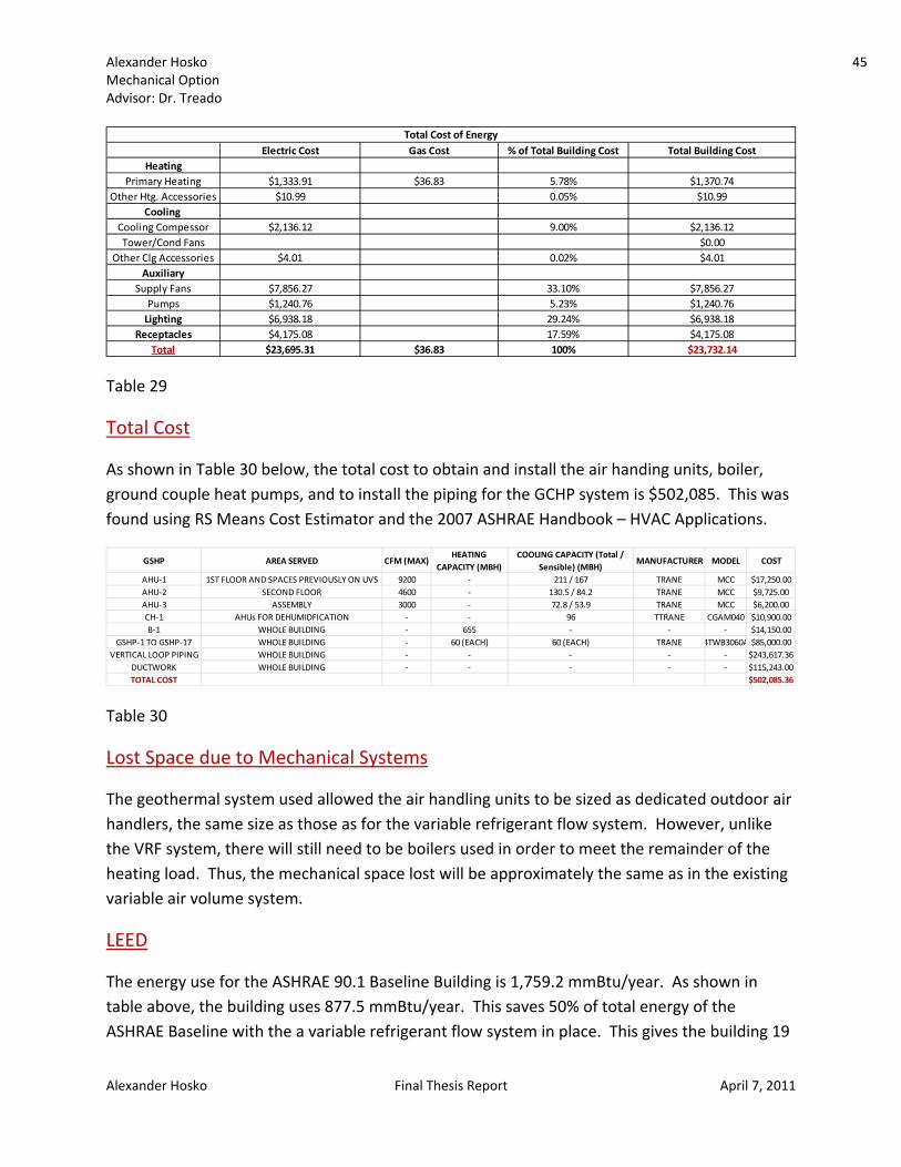
Table 29
Total Cost
As shown in Table 30 below, the total cost to obtain and install the air handing units, boiler, ground couple heat pumps, and to install the piping for the GCHP system is $502,085. This was found using RS Means Cost Estimator and the 2007 ASHRAE Handbook – HVAC Applications.
Table 30
Lost Space due to Mechanical Systems
The geothermal system used allowed the air handling units to be sized as dedicated outdoor air handlers, the same size as those as for the variable refrigerant flow system. However, unlike the VRF system, there will still need to be boilers used in order to meet the remainder of the heating load. Thus, the mechanical space lost will be approximately the same as in the existing variable air volume system.
LEED
The energy use for the ASHRAE 90.1 Baseline Building is 1,759.2 mmBtu/year. As shown in table above, the building uses 877.5 mmBtu/year. This saves 50% of total energy of the ASHRAE Baseline with the a variable refrigerant flow system in place. This gives the building 19
Electric Cost Gas Cost % of Total Building Cost Total Building CostHeating
Primary Heating $1,333.91 $36.83 5.78% $1,370.74Other Htg. Accessories $10.99 0.05% $10.99
Cooling Cooling Compessor $2,136.12 9.00% $2,136.12Tower/Cond Fans $0.00
Other Clg Accessories $4.01 0.02% $4.01Auxiliary
Supply Fans $7,856.27 33.10% $7,856.27Pumps $1,240.76 5.23% $1,240.76Lighting $6,938.18 29.24% $6,938.18
Receptacles $4,175.08 17.59% $4,175.08Total $23,695.31 $36.83 100% $23,732.14
Total Cost of Energy
GSHP AREA SERVED CFM (MAX)HEATING
CAPACITY (MBH)COOLING CAPACITY (Total /
Sensible) (MBH)MANUFACTURER MODEL COST
AHU‐1 1ST FLOOR AND SPACES PREVIOUSLY ON UVS 9200 ‐ 211 / 167 TRANE MCC $17,250.00AHU‐2 SECOND FLOOR 4600 ‐ 130.5 / 84.2 TRANE MCC $9,725.00AHU‐3 ASSEMBLY 3000 ‐ 72.8 / 53.9 TRANE MCC $6,200.00CH‐1 AHUs FOR DEHUMIDFICATION ‐ ‐ 96 TTRANE CGAM040 $10,900.00B‐1 WHOLE BUILDING ‐ 655 ‐ ‐ ‐ $14,150.00
GSHP‐1 TO GSHP‐17 WHOLE BUILDING ‐ 60 (EACH) 60 (EACH) TRANE 4TWB3060A $85,000.00VERTICAL LOOP PIPING WHOLE BUILDING ‐ ‐ ‐ ‐ ‐ $243,617.36
DUCTWORK WHOLE BUILDING ‐ ‐ ‐ ‐ ‐ $115,243.00TOTAL COST $502,085.36

Alexander Hosko 46 Mechanical Option Advisor: Dr. Treado
Alexander Hosko Final Thesis Report April 7, 2011
of a possible 19 LEED points in the under EA Credit 1: Optimize Energy Performance. The Army Reserve Center will thus receive 46‐52 LEED points and obtain a gold or platinum rating.
Greenhouse Gases
As explained in Tech Report 2, Rhode Island is part of the Eastern Interconnection which uses primarily coal (53.9%), nuclear (23.0%) , and natural gas (12.7%) for electricity generation. Shown below in Table 31 and Table 32 is the total electrical and natural gas usage of the Army Reserve Center with a GCHP system, and the emissions that are created when this system is implemented.
Table 31 (above)
Table 32 (above)
TOTAL ELECTRICAL USAGE (kWh)
TOAL EMISSION FRACTION (LB / kWh)
TOTAL POLLUTION (LB)
CO2 1.64 417,180NOX 3.00 * 10^‐3 763SOX 8.57 * 10^‐3 2,180PM 9.26 * 10^‐5 2,356
TOTAL ELECTRICAL EMISSIONS FOR GSHP SYSTEM
254,378
TOTAL GAS USAGE (*1000 FT3)
TOAL EMISSION FRACTION (LB / 1000
FT3)
TOTAL POLLUTION (LB)
CO2 11.6 106,813NOX 0.0164 151SOX 1.22 11,234PM 0.002237 21
TOTAL GAS EMISSIONS FOR GSHP SYSTEM
9,208

Alexander MechanicaAdvisor: D
Alexander
Structu
As mentiUnits wilof the rorefrigera
Figure 17
The massbelow. T
The total
TAG MVRV‐1VRV‐2VRV‐3VRV‐4VRV‐5VRV‐6
Hosko al Option r. Treado
Hosko
ural Brea
oned in the l be added. of. As shownt volume u
7
s of each VRThey were tr
l dead load w
MANUFACTUDAIKINDAIKINDAIKINDAIKINDAIKINDAIKIN
dth
Variable ReThese units
wn in Figure 1units will be p
V unit is givereated as de
was first det
RER MOREYQ96REYQ12REYQ16REYQ16REYQ72REYQ96
Final
frigerant Flo will be plac17 below, thplaced as sh
en in the maad loads in d
termined bas
DEL MAS6PYDN 720PYDN 768PYDN 1068PYDN 102PYDN 76PYDN 7
l Thesis Report
ow section, Ded on the rohe roof is broown in Figu
anufacturer’determining
Table
sed on data
SS (LB)732732036036732732
t
Daikin Variaboof, thus chaoken up intore 17 below
s catalog ang the roof str
e 33
shown in Ta
ble Refrigeraanging the sto 30’x30’ bayw.
nd is shown iructure.
able 34 belo
April 7
ant Volume tructural deys. The varia
n Table 33
w.
7, 2011
sign able
47

Alexander MechanicaAdvisor: D
Alexander
Next, thea 30 psf s1.5B20 ro
Table 35
To size thand girdewas dete
VRV UNITSTANDININSULATAPPROXITOTAL
Hosko al Option r. Treado
Hosko
e total load osnow load aoof deck, hig
he joists anders were incermined that
TSNG SEAM METIONIMATE DECK S
TOTAL DEA
on the roof dnd a 20 psf lghlighted in
d girders, theluded. Usint 28K8 joists
TAL ROOF
SELF WEIGHT
AD LOAD (psf
Final
deck was fouive load. ThTable 35 be
e same loadsg the Standa will be used
323
T 311
f)
l Thesis Report
Table 34
und. This inche total loadlow, will be
s were used ard LRFD Load as shown i
t
cluded the d was found tused.
except thatad Table fron Table 36 b
Ta
dead load, bto be 61 psf
t the self‐wem the Steel below.
ble 36
April 7
ut also assuf. A Vulcraft
ight of the joJoist Institut
7, 2011
med
oists te, it
48

Alexander MechanicaAdvisor: D
Alexander
Likewise,Construc
A detaile
Hosko al Option r. Treado
Hosko
, using the Fction, it was
ed calculatio
lexural Desigdetermined
n is located
Final
gn Tables pr that W10x5
in Appendix
l Thesis Report
rovided by th54 girders wi
x A.
t
he Americanill be used a
Table
n Institute ofs shown in T
e 37
April 7
f Steel Table 37 belo
7, 2011
ow.
49
Alexander MechanicaAdvisor: D
Alexander
Acoust
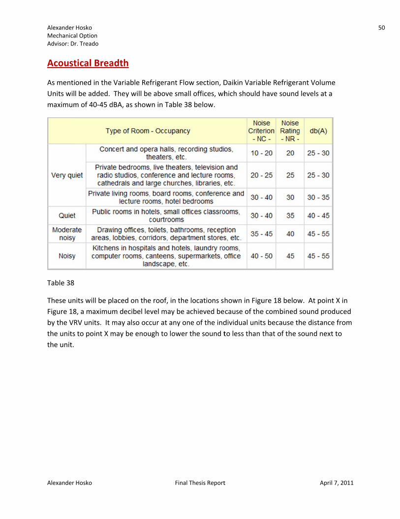
As mentiUnits wilmaximum
Table 38
These unFigure 18by the VRthe unitsthe unit.
Hosko al Option r. Treado
Hosko
tical Brea
oned in the l be added. m of 40‐45 d
nits will be p8, a maximumRV units. It ms to point X m
adth
Variable ReThey will be
dBA, as show
laced on them decibel lemay also occmay be enou
Final
frigerant Floe above smawn in Table 3
e roof, in thevel may be acur at any onugh to lower
l Thesis Report
ow section, Dall offices, wh38 below.
e locations shachieved bene of the indr the sound t
t
Daikin Variabhich should
hown in Figucause of thedividual unitto less than
ble Refrigerahave sound
ure 18 belowe combined ts because ththat of the s
April 7
ant Volume levels at a
w. At point Xsound produhe distance fsound next t
7, 2011
X in uced from to
50

Alexander MechanicaAdvisor: D
Alexander
Figure 18
Accordinshown in
From thefrequenc
The soun
dB = 10 l
dB = souI = the inI0 = the re
TAVRVVRVVRVVRVVRVVRV
Hosko al Option r. Treado
Hosko
8
g to the spen Table 39 be
e specificatiocy of 60 hert
nd level of ea
og (I / I0)
nd level in dtensity eference int
AGV‐1 REV‐2 REYV‐3 REYV‐4 REYV‐5 REV‐6 RE
DIAKIN
ecifications, telow.
ons, the unitz. The soun
ach individu
decibels (adju
tensity
MODELEYQ96PYDNYQ120PYDNYQ168PYDNYQ168PYDNEYQ72PYDNEYQ96PYDN
N VRV UNITS
Final
the variable
ts operate atd is measure
al unit at po
usted so dBA
dBA586061615858
l Thesis Report
refrigerant
Table 39
t 460 volts aed at a point
oint X is foun
A will be use
t
volume unit
nd the sount 3.3 feet in
nd by using t
ed)
ts have the d
nd is producefront of the
he following
April 7
decibel level
ed at a e unit.
g equations:
7, 2011
s
51
Alexander MechanicaAdvisor: D
Alexander
I1 / I2 = (d
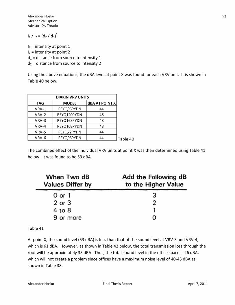
I1 = intenI2 = intend1 = distad2 = dista Using theTable 40
The combelow. It
Table 41 At point which is roof will which wishown in
TAGVRV‐VRV‐VRV‐VRV‐4VRV‐VRV‐
Hosko al Option r. Treado
Hosko
d2 / d1)2
nsity at pointnsity at pointance from soance from so
e above equbelow.
bined effectt was found
X, the sound61 dBA. Howbe approximll not createn Table 38.
M1 REYQ2 REYQ3 REYQ4 REYQ5 REYQ6 REYQ
DIAKI
t 1 t 2 ource to inteource to inte
ations, the d
t of the indivto be 53 dB
d level (53 dwever, as shmately 35 dBe a problem
MODEL dQ96PYDNQ120PYDNQ168PYDNQ168PYDNQ72PYDNQ96PYDN
N VRV UNITS
Final
ensity 1 ensity 2
dBA level at
vidual VRV uA.
BA) is less thhown in TablBA. Thus, thesince offices
dBA AT POIN444648484444
S
l Thesis Report
point X was
Table 40
nits at point
han that of tle 42 below,e total souns have a max
NT X
t
found for e
0
t X was then
the sound lev the total trad level in thximum noise
each VRV uni
n determined
vel at VRV‐3ansmission le office space level of 40‐
April 7
it. It is show
d using Table
3 and VRV‐4,loss throughce is 26 dBA,‐45 dBA as
7, 2011
wn in
e 41
, h the ,
52
Alexander MechanicaAdvisor: D
Alexander
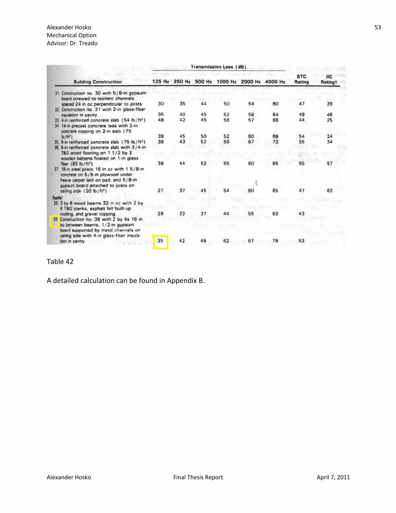
Table 42 A detaile
Hosko al Option r. Treado
Hosko
ed calculation can be fou
Final
und in Appen
l Thesis Report
ndix B.
t April 77, 2011
53

Alexander Hosko 54 Mechanical Option Advisor: Dr. Treado
Alexander Hosko Final Thesis Report April 7, 2011
System Comparison and Recommendation
Table 43
As shown in Table 43 above, there are advantages in cost, energy use, and saved mechanical space in replacing the existing variable air volume system with either a variable refrigerant flow system or a ground couple heat pump system. The ground couple heat pump system uses 86% of the total energy of the variable refrigerant flow system and only 72% of the energy of the variable air volume system. This saves $3651 per year compared to the VAV system and $4051 when compared to the VRF system. However, the first cost of the variable refrigerant flow system is only 56% of the cost of the ground couple heat pump system.
Although the VRF system cost is the cheapest based on the equipment costs found, this number may be misleading. Variable refrigerant flow systems are used commonly in Europe. Thus, the numbers for the equipment was found in euros and then converted to US dollars. The equipment may be slightly more expensive if it was ordered for a job in the United States. Also, the cost of installation, estimated using RS Means, may be slightly higher because there are not many contractors with experience in VRF systems. Another disadvantage of a VRF system is that extra maintenance may have to be hired in order to operate a VRF system. If an extra employee needs to be hired, this would add an annual cost of at least $40,000 per year, thus making the energy savings and first cost savings not worth it for a VRF system.
One predicted advantage with using a VRF system or a GCHP that hopefully would have occurred was decreasing the size of ductwork due to it only providing outside air and handling the latent load. The first floor ductwork was relatively the same size as with the VAV; however, the second floor ductwork was able to be shrunk. This is because the latent load on the first floor is high relative to the sensible load whereas the second floor is dominated by the sensible load. Less ductwork is used which will provide cost savings and reduce the pressure in ducts (and thus noise); however, it was not as much as predicted.
Although the variable refrigerant flow system uses less energy, the annual cost of energy is the greatest. This is because electricity is used for heating and the price of electricity is currently high relative to the price of natural gas, which is used for heating in the variable air volume
ANNUAL ENERGY USE (mmBtu/yr) FIRST COST ANNUAL ENERGY COSTMECHANICAL
SPACE SAVED (FT)VAV 1,227 $301,410.00 $27,384.00 ‐VRF 1018 $283,105.00 $27,784.00 800GSHP 878 $502,086.00 $23,733.00 ‐
SYSTEM COMPARISON

Alexander Hosko 55 Mechanical Option Advisor: Dr. Treado
Alexander Hosko Final Thesis Report April 7, 2011
system and used for some heating in the ground couple heat pump system. The annual energy cost would thus change in upcoming years based on the change in the price of natural gas relative to that of electricity.
The most logical system selected for the Army Reserve Center would be the ground couple heat pump system, based on solely energy consumption and cost of energy per year. However, the payback for the system is 54 years which is certainly not worth the extra added cost. Based on information from the National Institute of Standards and Technology, energy is not supposed to escalate much relative to inflation. Thus, a drastic change in the cost of energy is not expected to occur, which makes the simple payback of 54 years to be an accurate estimate, and certainly not justifiable. Thus, based on a combination of energy consumption, first cost, and saved mechanical space, the variable refrigerant flow system should be selected, assuming that extra maintenance would not be required.

Alexander Hosko 56 Mechanical Option Advisor: Dr. Treado
Alexander Hosko Final Thesis Report April 7, 2011
References
ASHRAE. (2007). Standard 62.1 ‐ 2007, Ventilation for Acceptable Indoor Air Quality. Atlanta, GA: American Society of Heating Refrigeration and Air Conditioning Engineers, Inc. ASHRAE. (2007). Standard 90.1 ‐ 2007, Energy Standard for Buildings Except Low‐Rise Residential Buildings. Atlanta, GA: American Society of Heating Refrigeration and Air Conditioning Engineers, Inc. Michel Baker Corporation. Construction Documents & Specifications. 101 Airside Drive, Pittsburgh, PA, 15108. Deru & Torcellini. (2007). Source Energy and Emission Factors for Energy Use in Buildings. National Renewable Energy Laboratory. Trane Trace 700. Mumma, Stanley A. “Designing Dedicated Outdoor Air Systems” ASHRAE Journal May (2001): pages 28‐31. 9 December 2010. Goetzler, William. “Variable Refrigerant Flow Systems” ASHRAE Journal April (2007): pages 24‐31. 9 December 2010. Kavanaugh, Steve. “Ground Source Heat Pumps for Commercial Buildings.” 1 Sept 2008. Web. 2 Dec 2010. <http://hpac.com/fastrack/ground‐source‐heat‐pumps/>. ASHRAE. 2007, ASHRAE, Handbook of HVAC Applications. American Society of Heating Refrigeration and Air‐Conditioning Engineeers, Inc., Atlanta, GA ASHRAE. 2009, ASHRAE, Fundamentals. American Society of Heating Refrigeration and Air‐Conditioning Engineeers, Inc., Atlanta, GA ASHRAE. 2008, ASHRAE, Systems and Equipment. American Society of Heating Refrigeration and Air‐Conditioning Engineeers, Inc., Atlanta, GA Daikin. VRV III Engineering Data. 1645 Wallace Drive, Suite 110, Carrollton, Texas, 75006. LG Electronics. “Introduction of VRF System.” HVAC Monthly Magazine (2007). 16 Jan 2011. RS Means Costworks. James, Zachary. 2001. Updating and Debugging the Federal Renewable Energy Screening Assistant: Ground Coupled Heat Pump Algorithm. National Renewable Energy Lab.
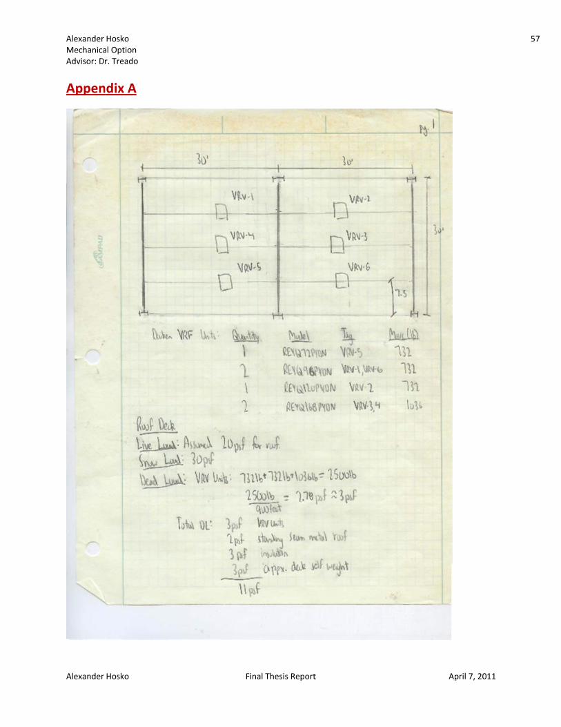
Alexander MechanicaAdvisor: D
Alexander
Appen
Hosko al Option r. Treado
Hosko
ndix A
Finall Thesis Reportt April 7
7, 2011
57

Alexander MechanicaAdvisor: D
Alexander
Hosko al Option r. Treado
Hosko Finall Thesis Reportt April 77, 2011
58
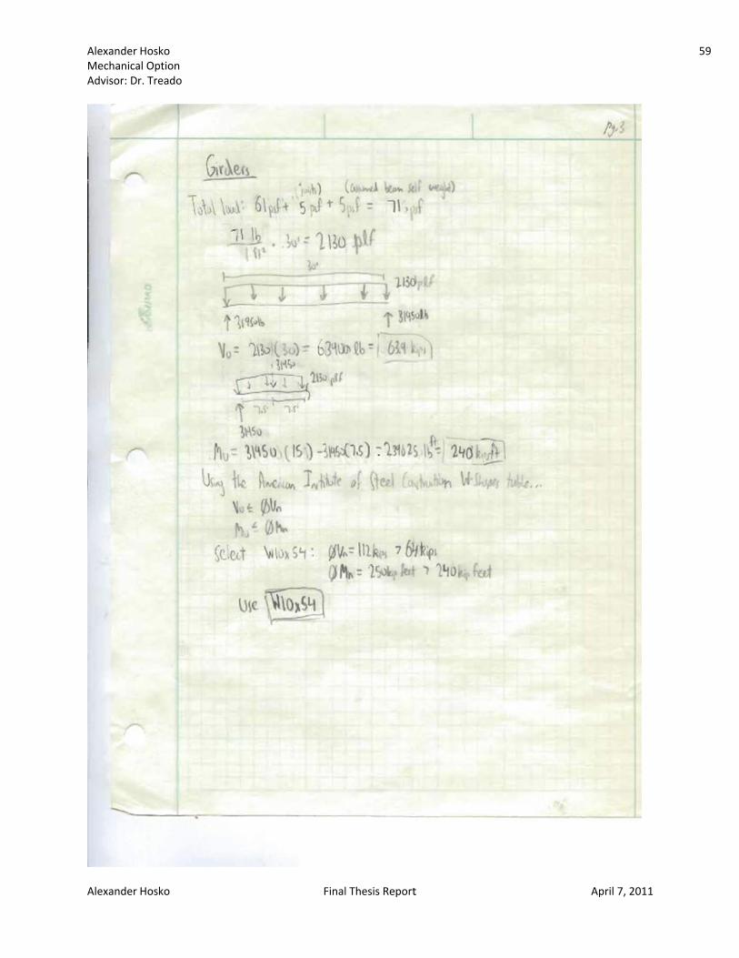
Alexander MechanicaAdvisor: D
Alexander
Hosko al Option r. Treado
Hosko Finall Thesis Reportt April 77, 2011
59

Alexander MechanicaAdvisor: D
Alexander
Hosko al Option r. Treado
Hosko Finall Thesis Reportt April 77, 2011
60

Alexander MechanicaAdvisor: D
Alexander
Appen
Hosko al Option r. Treado
Hosko
ndix B
Finall Thesis Reportt April 7
7, 2011
61

Alexander MechanicaAdvisor: D
Alexander
Hosko al Option r. Treado
Hosko Finall Thesis Reportt April 77, 2011
62

Alexander MechanicaAdvisor: D
Alexander
Hosko al Option r. Treado
Hosko Finall Thesis Reportt April 77, 2011
63


