PROJECT REPORT EICHER ENGINES, ALWAR (A Unit of TAFE Motors & Tractors Limited) A Wholly Owned Subsidiary of TAFE Department of Mechanical engineering Sunrise faculty of engineering, Udaipur Page 1
Transcript
PROJECT REPORT
EICHER ENGINES, ALWAR(A Unit of TAFE Motors & Tractors Limited) A Wholly Owned Subsidiary of TAFE
(A Unit of TAFE Motors & Tractors)
Department of Mechanical engineering Sunrise faculty of engineering, Udaipur Page 1
PROJECT REPORT(INDUSTRIAL TRAINING MAY-JULY2016)
Dissertation Report Submitted on Metallurgical testing Of Valtra Engine Component
RAJASTHAN TECHNICAL UNIVERSITY, KOTATowards The Partial Fulfillment for the Course Of
Bachelor of EngineeringBy
Arpit JainRoll no.-13EIUME007
B.tech mechanical engineering2013-17
SUBMITTED TO-: GUIDE BY-: Mr. Rahul Kumar Mr. Shelender Sharma Jr. Manager-QSA Manager EICHER ENGINES, ALWAR EICHER ENGINES, ALWAR
Department of Mechanical engineering Sunrise faculty of engineering, Udaipur Page 2
INDEXS.No.
Topic Page no.
1 Declaration 32 Acknowledgement 43 Introduction about company 54 Product range 85 Eicher engine product 96 Process flow chart 137 An over look into the system of Eicher Engines 158 Project - Inspection of The Composition of
Material Valtra Engine Component 23
9 Conclusion 5810 References 59
Department of Mechanical engineering Sunrise faculty of engineering, Udaipur Page 3
DECLARATIONI hereby declare that the project work entitled “Inspection of The Composition of Material Of Valtra Engine Component” is an authentic record of my own work carried out at EICHER ENGINES (TMTL), Alwar as requirement of two month (sixty days) project semester for the award of degree of B.tech Mechanical Engineering, Rajasthan technical university, kota, under the guidance of Mr. Rahul kumar during may to july2016. The empirical findings in this report are based on the data educated myself. This is my original work and cannot be submitted partially or wholly to any other university or institute for award of this or any other degree or diploma.
Arpit Jain
Date: - ……………… roll no.:- 13eiume007
Certified that the above statement made by the student is correct to the best of our knowledge and belief.
………………
Vibhu Joshi Asst. manager,
Human resource, TMTL, Alwar,
Department of Mechanical engineering Sunrise faculty of engineering, Udaipur Page 4
AcknowledgementBefore I start with the details of my project, I would like to add a few heartfelt words for the people who were the part of my project in numerous ways, the people who gave me the immense support right from the stage from the stage where I was novice to the engines industry.
First of all I would like to express my deep sense of gratitude to Mr. Sudhir Jain, who gave me opportunity to undertake training in this organization. I have appreciation and regards for their constant encouragement, constructive criticism and sympathetic understanding throughout the course of this training.
I would like to thank my mentor Mr. Rahul kumar (Jr. Manager-QSA) for those opportunities he gave me to share his ideas and knowledge in a large variety of settings and sense of quality that I learnt from him are truly uncommon. I am very thankful to him for his wise and synergetic help throughout my training period.
I would like to thank whole metallurgy department and RQC department team for always helped me in increasing my knowledge and understanding of working in an organization.
I express my gratitude to all the other employees of Eicher Engines for making my training at the company wonderful experience.
Arpit
Department of Mechanical engineering Sunrise faculty of engineering, Udaipur Page 5
INTRODUCTION ABOUT COMPANY Established in 1961 Chennai based amalgamation group Turnover RS. 37000 Crores C.E.O. Mrs. Malika Srinivaasan In December 2003, TAFE acquired Eicher’s Tractor plant at Mandideep, Engines Plant at Alwar and
Transmission plant at Parwanoo through the formation of a wholly owned subsidiary, TAFE Motors and tractors Limited (TMTL)
TAFE PROFILETractors and farm equipment limited (TAFE) is a unit company of the amalgamation group , one of India’s largest light engineering group with diverse in diesel engines, automobile components, tractors and related farm machinery, lubricants, panel instrument, hydraulic pumps, engineering tools, storage batteries, paints, engineering plastics, automobile franchises and printing apart from interests in agribusiness , book selling and publishing.
TAFE was established in 1961 to manufacture and market a range of Massey Ferguson tractors and related farm equipment in India. One of the largest tractors manufactures in India, TAFE has collaboration with AGCO Corporation, headquartered in Duluth, Georgia, which is one of the largest manufactures, designers and distributors of agricultural equipment in the world.
TAFE was the first company to market a total package of tractors and farm equipment to not only provides farm power but also interfaces to transform the farm power to increased farm productivity. TAFE was also the first to introduce the direct injection technology in India. Thereby initiating considerable fuel saving and the result economies in tractors operation cost to its customers.
TAFE was also first Indian manufacturer to launch a 75 HP tractor to cater to the emerging need of very large farms and agri- businesses. Whit three manufacturing locations at Chennai (Sembiam), Madurai (kalladipatti) and Bangalore (Doddaballapur), TAFE has a large manufacturing base. Its Madurai plant, the latest and possibly the largest such plant in the country is specially tailored to take on short run production batches to the exacting standards demanded by advanced countries. All its plant and sales offices are linked by VSAT providing fast and efficient communications and data linkage another first of its kind in India.
Department of Mechanical engineering Sunrise faculty of engineering, Udaipur Page 6
TAFE is also involved in the following areas, apart from its core business of manufacturing and marketing tractors.
1. TAFE has developed a range of matching trailers, implements and accessories. These are marketed through TAFE’s dealer network by a totally owned subsidiary.
2. TAFE, through TAL is also involved in the marketing and distribution of lubricants and greases for tractors through its dealer network.
3. TAFE is also involved in the packaged power industry through its Power Source Division.
4. TAFE has also diversified into Engineering plastic and production of tools and dies for this industry.
5. TAFE’s vision is not just wishful thinking but based on recognized engineering, marketing and financial strengths, built up over the past four decades.
6. TAFE has in- house facilities for the manufacture of hydraulic pumps and gears for tractors. A related facility for the manufacturing of panel instruments, not only for captive use but also for the growing automobile industry in India is an integral part of the company.
7. To achieve the distinction of the first choice among the farming community of India and ensure a growing presence in international markets through setting leadership standards of performance and customer care in the agricultural machinery business
Department of Mechanical engineering Sunrise faculty of engineering, Udaipur Page 7
TMTL- A wholly owned subsidiary of TAFE (Tractors and Farm Equipment). TAFE is a unit company of the amalgamation group one of India’s largest light engineering group with diverse interests in diesel engines, auto mobile component s, tractors and related farm machinery, lubricants panel instruments, hydraulic pumps, engineering tool, storage batteries, engineering plastics, automobile franchises and printing apart from interests in agribusiness, book selling& publishing . The group’s leadership technology built on foreign know how has been nurtured through indigenous efforts.
TMTL has in three divisions in India – Tractor Division, Bhopal – Manufacture and Assembly of Tractors. Engine division, Alwar – Manufacture and Assembly of Auto & Stationary Engines. Transmission Division, Parwanoo – Manufacture of various Transmission components like Spur Gears, Helical Gears, Spline Shafts, Crown Wheel Pinion, and Cam Shaft.
Tractor division at Bhopal viz. Eicher tractors. Eicher tractors a pioneer in tractor manufacturing in India rolled out its first Indian tractor in 1959 with the collaboration of gerb-eicher, Germany in 1960. The other group company TAFE too is amongst the oldest tractor manufacturer in India and is manufacturing and selling Ferguson and TAFE range of tractors. TAFE and TMTL as a group is the second largest tractor manufacture in India. Jointly more than 25 tractor models and 100 variants. Which is the largest range being offered by any tractor manufacturer in India? Eicher India has manufacturing and design facilities in mandideep in Madhya Pradesh and producing 13 base models ranging from 24HP to 50HP. Eicher range of tractors enjoys unique advantages in terms of phenomenal fuel efficiency, Its easy maintenance, higher pulling capacity, reliability and suitability for farm and commercial applications.
Department of Mechanical engineering Sunrise faculty of engineering, Udaipur Page 8
EICHER ENGINE ALWAR Established in 1982 technical tie-up:-
Technology transfer from Ricardo of UK for developing air-cooled engines. Technology transfer from SISU (VELMET) Finland, for higher horse power
tractors.
Eicher Engines :- some awards and recognition
1994-95 Certificate of merit for productivity performance awarded by national productivity council
1996-97 Certificate of merit for productivity performance awarded by national productivity council
TECHNOLOGY IN EICHER:-Eicher has state of art Product development centre at Alwar facility, which has CREO, ANSYS, Auto CAD, Adams, Hyper mesh work stations, simulation rings, mechanical engine test beds and mock shop for developing new products. The plant has assembly lines, Co-ordinate Measurement Machines and conveyers for various product lines. Eicher puts a lot of emphasis on technology up gradation of its service network as well. Company uses IT as a business excellence and its home portal EPIC is widely used for all in-house daily management progress of information sharing. Leave planning. Performance appraisal and progress tracking etc. ERP package of SAP was established in 1999, which helps smooth transactions in supply chain management processes from supplier raw material planning to tractor delivery at sales outlets and demand forecasting.
Department of Mechanical engineering Sunrise faculty of engineering, Udaipur Page 9
PRODUCT RANGE
Tractor models :
• 241xtrac - 24hp tractor single cylinder air cooled• 242xtrac - 24hp tractor single cylinder air cooled• 312SDI - 30hp tractor two cylinder air cooled• 333SDI - 30hp tractor two cylinder water cooled• 364SDI - 35hp tractor two cylinder air cooled• 368SDI - 35hp tractor three cylinder air cooled• 380SDI - 35hp tractor three cylinder water cooled • 485SDI - 42hp tractor three cylinder air cooled• 480SDI - 42hp tractor three cylinder water cooled • 5150SDI - 47hp tractor three cylinder water cooled • 5660 - 52hp tractor three cylinder water cooled
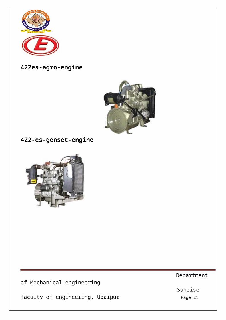
stationary Engines: 222ES/222HS - 18hp single cylinder 1500rpm rating 322ES - 24 hp two cylinder 1500 rpm rating 422ES - 34hp three cylinder 1500 rpm rating
EICHER ENGINES PRODUCT
Department of Mechanical engineering Sunrise faculty of engineering, Udaipur Page 10
222es-agro-engine 222-esg-genset-engine
321es-agro-engine 421es engine
Department of Mechanical engineering Sunrise faculty of engineering, Udaipur Page 11
Full form Related of engine model HS- Handle Start ES- Electric Start ESG- Electric Start Generator ESU- Electric Safety Unit GCU- Gen set Control Unit CPCB- Central Pollution Control board EGR- Exhaust Gas Recirculation ED- Engine Derated EDD- Engine Double Derated KVA- kilo Volt Ampere T.C- turbo Charger I.C- Inter Cooler
Department of Mechanical engineering Sunrise faculty of engineering, Udaipur Page 13
Process Flow Chart
RAW MATERIAL IN THE FORM OF CASTING AND FORGING SHALL BE INSPECTED FOR PARAMETER AS PER SPECIFICATION / DRAWING AND SENT TO STORE COMPONENTS LIKE PISTON, LINER, BLOWER SHAFT
ETC. SHELL BE SENT FOR SUB-ASSEMBLY PRIOR TO ITS PERFORMANCE AND THEN PAINTED. THE PAINTED ENGINE IS SUBJECTED TO PRE-
DISPATCH INSPECTION PRIOR TO ITS DISPATCH AS FINAL PRODUCT.
Department of Mechanical engineering Sunrise faculty of engineering, Udaipur Page 14
DEPARTMENTS IN EICHER ENGINES, ALWAR PRODUCT DEVELOPMENT CENTER FINANCE AND ACCOUNTS DEPARTMENT SALES AND MARKETING DEPARTMENT MATERIALS/VENDOR DEVELOPMENT STORE DEPARTMENT QUALITY ASSURANCE DEPARTMENT DESIGN RELEASE DEPARTMENT PRODUCTION DEPARTMENT MAINTENANCE DEPARTMENT ENGINEERING & PROJECTS HUMAN RESOURSES DEPARTMENT
AN OVER LOOK INTO THE SYSTEM OF EICHER ENGINESThere are following basics departments in Eicher Engine Department of Mechanical engineering Sunrise faculty of engineering, Udaipur Page 15
1. PRODUCT DEVELOPMENT CENTER This department is responsible for designing the products to be manufactured by the different vendors.
2. FINANCE AND ACCOUNTS DEPARTMENT This department is responsible for all the financial transforms that are carried out in the company such as payments for all the incoming material, salaries of all the employees, all the records for expenditures and credits to the company are maintained by this department.
3. SALES AND MARKETING DEPARTMENT This department is responsible for consolidating the position of the company in the market every year. Every year these people get some new strategies so as to increase the share of the company in the market most of the sales of the company are dependent on the working of this department thus being one of the most important departments.
4. MATERIALS/VENDOR DEVELOPMENT This department is responsible for all the incoming material from the vendor. This department is further divided into two departments.
a) Vendor Development All the new samples and in fact all the new components are developed by this department. All the components developed are not consumed as a part of the regular production but implemented as a trial only and consumed in regular production only after these components are regularized.
b) Purchase Department This department is responsible for all the incoming material brought in that is used in regular production.
5. STORE DEPARTMENT
Department of Mechanical engineering Sunrise faculty of engineering, Udaipur Page 16
This department is responsible for the handling of the incoming material, supplying the material on to the line and also the dispatch the rejected materials back to the vendors.
6. QUALITY ASSURANCE DEPARTMENTThis department is responsible for overall quality control of the incoming components and assurance about the quality of the engines to the customer.
Quality can be defined as “fitness for use” when we talk of quality it means that product should be fit for use and it is the user who judges and decides what qualities he wants in the product.The Quality Characteristics Can Be Grouped Into Four Categories:
a. Quality of designb. Quality of conformancec. Availabilityd. Customer service
The Various Sub-Departments Of Quality Assurance Department Are:
a. Metallurgical labb. Standard roomc. Development celld. Receipt quality controle. Manufacturing quality control.
Sample validation:-If there are some changes to be made or any new component is to install a lot of five samples is to be brought to the sample room for verification purposes. Then the sample is
Passed on depending upon its department purpose is to check the components of new vendor.
Department of Mechanical engineering Sunrise faculty of engineering, Udaipur Page 17
The objectives of sample validation department are: To assure the dimensional and other characteristics of new sample are conforming
to the specification. To make quality standards along with materials department to ensure the
characteristics of components over long period of time.
Metallurgical lab:-
This lab has all facilities to determine the chemical composition of the raw material used for the production of various components. This lab includes universal testing machine, Rockwell machine, brinell hardness tester, rubber testing machine, chemicals for determine the microstructure of the raw material, rubber tensile testing equipment.
The objectives of metallurgy lab:-
To ensure all components should be free from any sort of non-conformance related to physical chemical aspects per relevant standards. To ensure the quality of paints rubber items.
Standard room:-
This department houses all the measuring instruments and their records. It is a fully air conditioned room with dust free environment. The room is specially made dust proof for avoiding any measurement anomalies. CMM machine is installed here which is used to check the components for better accuracy.
Objectives of Standard room:-
To perform calibration of the various instruments in various department.
Department of Mechanical engineering Sunrise faculty of engineering, Udaipur Page 18
To demonstrate the confidence level of measurement system to the customer.
Gauge planning and procurement from the vendor for calibration.
7. DESIGN RELEASE DEPARTMENT:-This department deals with product development of new tractors as was Valtra
when it was developed last year. Basically this department coordinates between design and various divisions.
Objectives of design release department:- New design implementation. To coordinate different department while new design is to be
implemented. Review of components according to quality aspects and design review.
Receipt quality control:-Receipt quality control (RQC) may be defined as the sum of the measurement taken by the receivers to assure the quality or material offered by vendor. This development receives the components from the vendor and assures mainly the dimensional aspect and also the appearance of the component. This department has a very large list of gauges and instrument, which are duly calibrated according to date; Adherence and tractability to the is there.The clearing of components includes evaluating the sample size from each lot; the components are checked for various aspects and then send for confirmation or rejection.
Objective of Receipt quality control (RQC):-
Department of Mechanical engineering Sunrise faculty of engineering, Udaipur Page 19
To assure the quality of a particular unit or group of units submitted for acceptance.
To assure quality characteristics over the long term will meet with the quality standards.
The Receipt quality control (RQC) department is sub divided into four sections as materials there are
I. Sheet metal II. Casting
III. ForgingIV. Bar stock
Manufacturing quality control:-The department deals with the manufacturing quality. To ensure this quality, various audits are conducted like FIFO (first in first out), torquing, functional audit, settings and various alignments, bearing, final product audit etc.
Judging the conformity of the established standard and taking suitable action when deviation is noted.
To assure that these standards are implemented by conducting daily audits and upgrading the standards as and when required.
8. PRODUCTION DEPARTMENT:-This department is responsible for carrying out all the assembly operations. This department is further sub-divided into some of the parts as per different assembly lines such as hydraulics assembly line, transmission line, pre-painting line, paint kitchen, post painting line, PDI etc.
a. Maintenance department b. Store
Department of Mechanical engineering Sunrise faculty of engineering, Udaipur Page 20
a. Maintenance department:- For regular and prevent maintenance of machines and other equipment used for assembly this department provides its services.
b. Store:- Store assures regular rand continuously supply to avoid line stopping. All the materials purchased are stored here systematically and items that can be rusted are applied with rust preventive oil once in a week and in season in a week.
9. ENGINEERING & PROJECTS:-This department deals with the shop floor problems and identifies the potential areas for improvement by studying the existing facilities which leads to layout modification, Structure modification and also lead to the designing of trolleys and tackles. It also participates in discussion for selection and finalization of new machine tools, which involves the studying of tooling requirement and then makes the tooling available and establish them.Capacity enhancement like building new storages, new assembly areas, and offices as per the future plan of the plant is also one of the works done by department. Nearly all kinds of machines, presses, wrenches etc are handed over by engineering department.
10. MAINTENANCE DEPARTMENT:-This department is responsible for carrying out all the maintenance work to be carried out in the plant. Any kind out of repair work or maintenance such as electrical maintenance, this department carries out working of equipment on the assembly line etc.
Department of Mechanical engineering Sunrise faculty of engineering, Udaipur Page 21
11. HUMAN RESOURSES DEPARTMENT:-This is the most important department of any organization. As we all know that 3 M’s are most vital for any production unit. These 3M’sare men, materials and
machines, out of all the, men or human resource is the most complicated or important resource for any organization, the department which performs all the functions relating to the human resource is known as HUMANRESORCE MANAGEMENT . Human resource department is divided into three parts:
Corporate HR Plant HR Marketing HR
12. ADMINISTRATION :-The department look for the reception of the company, Security of the plant, greenery of the plant, transport facilities etc.
13. CENTRE OF EXCELLENCE:-The function of the department is creating the work culture in the company. Look for the certification of the company. Currently have TS 16949:2002 and ISO 14001:2004 and going for the OHSAS 18001:2007 and the vision of the department is to get Deming prize in 2016.
Department of Mechanical engineering Sunrise faculty of engineering, Udaipur Page 22
MATERIALS
Material department is the heart of any assembly unit. This department requires people with extreme passion for their work and those who can get things done at the lowest cost. The basic function of material department is to provide the production unit with all the components required for assembly. People in this department have to make sure that whatsoever material is required for day’s production is provided. At Eicher thousand of component has to be provided from a network of around 600 vendors from different states. Material department usually works overtime to see that they get material from this vast vendor network despite rain, strikes and delays in transportation due to breakdown of transport vehicles etc. here everybody work as a part of a team because even if a single component is not in adequate quantity then despite the presence of all other components line will stop and this will not be the failure of an individual but failure of materials department as a whole.
Department of Mechanical engineering Sunrise faculty of engineering, Udaipur Page 23
PROJECT Metallurgical Testing of
Valtra Engine Component
Metallurgical lab:-
Department of Mechanical engineering Sunrise faculty of engineering, Udaipur Page 24
This lab has all facilities to determine the chemical composition of the raw material used for the production of various components.
This lab includes Rockwell hardness tester Universal testing machine Brinell hardness tester Rubber and plastic tensile tester Chemicals for determine the micro-structure of the raw material
The objectives of metallurgy lab:-
To ensure all components should be free from any sort of non-conformance related to physical chemical aspects per relevant standards. To ensure the quality of paints rubber items.
Rockwell hardness tester
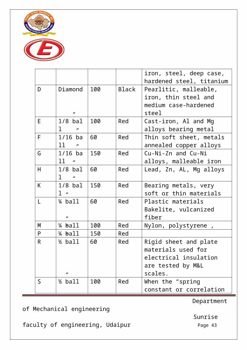
SCALES:-Scale Indicator Load
Kgf.Dial Application
Department of Mechanical engineering Sunrise faculty of engineering, Udaipur Page 25
A Diamond 60 Black Carbides, thin steel, shallow case-hardened steel case carburized surface
B 1/16”ball 100 Red Aluminum alloys, copper alloys, unhardened steel etc. in rolled drawn, extruded or cast metal.
C Diamond 150 Black HCI, pearlitic malleable iron, steel, deep case, hardened steel, titanium
D Diamond 100 Black Pearlitic, malleable, iron, thin steel and medium case-hardened steel
E 1/8”ball 100 Red Cast-iron, Al and Mg alloys bearing metal
F 1/16”ball 60 Red Thin soft sheet, metals annealed copper alloys
G 1/16”ball 150 Red Cu-Ni-Zn and Cu-Ni alloys, malleable iron
H 1/8”ball 60 Red Lead, Zn, AL, Mg alloysK 1/8”ball 150 Red Bearing metals, very soft or thin
materialsL ¼”ball 60 Red Plastic materials Bakelite,
vulcanized fiberM ¼”ball 100 Red Nylon, polystyrene , P ¼”ball 150 RedR ½”ball 60 Red Rigid sheet and plate materials
used for electrical insulation are tested by M&L scales.
S ½”ball 100 Red When the “spring constant or correlation factor is included in the test procedure only R scale is used.
V ½”ball 150 Red
Rockwell hardness tester:-
The Rockwell scale is a hardness scale based on indentation hardness of a material. The Rockwell test determines the hardness by measuring the depth of
Department of Mechanical engineering Sunrise faculty of engineering, Udaipur Page 26
penetration of an indenter under a large load compared to the penetration made by a preload. There are different scales, denoted by a single letter, that use different loads or indenters. The result is a dimensionless number noted as HRA, HRB, HRC, etc., where the last letter is the respective Rockwell scale.
When testing metals, indentation hardness correlates linearly with tensile strength. This important relation permits economically important nondestructive testing of bulk metal deliveries with lightweight, even portable equipment, such as hand-held Rockwell hardness testers. The determination of Rockwell hardness of material involves the application of a minor load followed by a major load. The minor load establishes the zero position. The major load is applied, and then removed while still maintaining the minor load. The depth of penetration from the zero data is measured from a dial, on which a harder material gives a higher number. That is, the penetration depth and hardness are inversely proportional. The chief advantage of Rockwell hardness is its ability to display hardness values directly, thus obviating tedious calculations involved in other hardness measurement techniques.
It is typically used in engineering and metallurgy. Its commercial popularity arises from its speed, reliability, robustness, resolution and small area of indentation.
In order to get a reliable reading the thickness of the test-piece should be at least 10 times the depth of the indentation. Also, readings should be taken from a flat perpendicular surface, because convex surfaces give lower readings. A correction factor can be used if the hardness of a convex surface is to be measured.
Department of Mechanical engineering Sunrise faculty of engineering, Udaipur Page 27
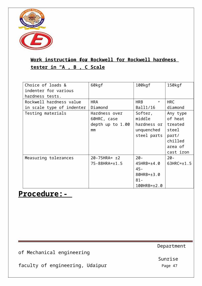
Work instruction for Rockwell for Rockwell hardness tester in “A”,”B”,”C”Scale
Choice of loads & indenter for various hardness tests.
60kgf 100kgf 150kgf
Rockwell hardness value in scale type of indenter
HRADiamond
HRBBall1/16”
HRCdiamond
Testing materials Hardness over 60HRC, case depth up to 1.00 mm
Softer, middle hardness or unquenched steel parts
Any type of heat treated steel part/ chilled area of cast iron
Measuring tolerances 20-75HRA= ±275-88HRA=±1.5
20-45HRB=±4.045-80HRB=±3.081-100HRB=±2.0
20-63HRC=±1.5
Procedure:-
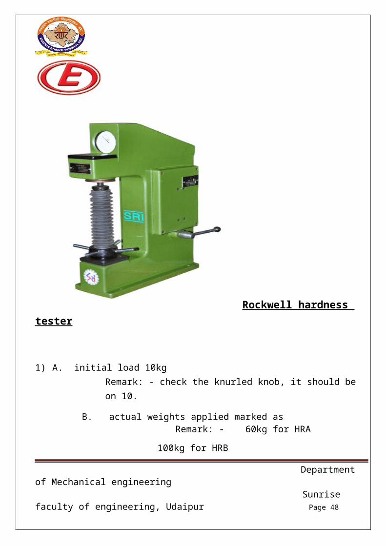
Rockwell hardness tester
Department of Mechanical engineering Sunrise faculty of engineering, Udaipur Page 28
1) A. initial load 10kgRemark: - check the knurled knob, it should be on 10.
B. actual weights applied marked as Remark: - 60kg for HRA
100kg for HRB
150kg for HRC
C. indenter
Remark: - diamond for the HRA and HRC scale & ball dial 1/16” for HRB scale.
D. hardness scale
Remark: - outer black dial reading for HRA & HRC.
2) Keep the master block/ component on table of hardness tester.
3) Making sure to choose right penetrator.Remark: - diamond indenter for the HRA and HRC scale and Ball dials 1/16” indenter for HRC scale.
4) Miner load apply on master pcs by 2.5 rotation of dial or up to 3 noc indication mark of dial (red dot)
Remark: - during minor load apply; the lever should be on inspector side.
5) Rotating the working plate slowly to support up the penetrator till small finger of indicator points at the red mark, the big finger turns 3 circles and stop vertically on the zero reading of the dial.
Remark: - ensure small finger stay on 3 (red marked) & bid finger stay on 0 (rounded black scale)
Department of Mechanical engineering Sunrise faculty of engineering, Udaipur Page 29
6) Turning the test force knob to test force thru rotating hydraulic lever.
7) Pulling the loading handle to apply main test force as arrow direction, at this moment the big finger of dial indicator rotates anticlockwise.
Remark: - making sure that lever position should be opposite the inspector after applied the test force (60kg for HRA, 100kg for HRB and 150kgf HRC.)
8) Hold loading handle at this stage up to dial Niddle stop.
9) Pushing back the unloading handle to release the main test force after the big finger of indicator stops clearly.
Remark: - leaver position should be on inspector side.
10) Waiting for big finger fixed on one data and getting the hardness value of the standard block / components.
Remark: - getting the hardness value as mentioned:-1. For HRA/HRC= full round black colored scale.2. For HRB= full round red colored scale.
Department of Mechanical engineering Sunrise faculty of engineering, Udaipur Page 30
Universal testing machine:-A universal testing machine (UTM) also known as a universal tester materials testing machine or material test frame, is used to test the tensile strength and compressive strength of materials. The “universal” part of the name reflects that it can perform many standard tests on materials, components, and structures (in other words, that it is versatile).
Components:- Load frames – Usually consisting of two strong supports for the machine
some small machine have a single support. Load cell – A force transducer or other means of measuring the load is
required. Periodic calibration is usually required by governing regulations or quality system.
Cross head – A movable cross head (crosshead) is controlled to move up or down. Usually this is at a constant speed: sometimes called a constant rate of extension (CRE) machine. Some machine can program the crosshead speed or conduct cyclical testing, testing at constant force, testing at constant deformation, etc. electromechanical, servo-hydraulic, linear drive, and resonance drive are used.
Means of measuring extension or deformation many tests require a measure of the test specimen to the movement of the cross head. Extensometers are sometimes used.
Output device – A means of providing the test result is needed. Some older machines have dial or digital displays and chart recorders. Many newer machines have a computer interface for analysis and printing.
Conditioning – Many tests require controlled conditioning (temperature, humidity, pressure, etc.). The machine can be in a controlled room or a specimen for the test.
Text fixtures, specimen holding jaws, and related sample making equipment are called for in many test methods.
Department of Mechanical engineering Sunrise faculty of engineering, Udaipur Page 31
Use:- The setup and usage are detailed in a test method, often published by a standards organization. This specifies the sample preparation, Fixturing, gauge length (The length which is under study or observation), analysis, etc.
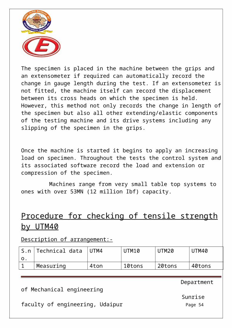
The specimen is placed in the machine between the grips and an extensometer if required can automatically record the change in gauge length during the test. If an extensometer is not fitted, the machine itself can record the displacement between its cross heads on which the specimen is held. However, this method not only records the change in length of the specimen but also all other extending/elastic components of the testing machine and its drive systems including any slipping of the specimen in the grips.
Once the machine is started it begins to apply an increasing load on specimen. Throughout the tests the control system and its associated software record the load and extension or compression of the specimen.
Machines range from very small table top systems to ones with over 53MN (12 million Ibf) capacity.
Procedure for checking of tensile strength by UTM40Description of arrangement:-
Department of Mechanical engineering Sunrise faculty of engineering, Udaipur Page 32
Universal testing machineSteps:-
1) First of all ensure the zero setting by Appling the hydraulic load without components. Remark: - the load- indicator zero and the plot-load-axis zero, if applicable, should be set before the specimen is placed in the grips. Zeroes should never be reset after the specimen is in place.
2) Select the weight as per section of tonnage.Remark:-
4TON – only pendulum10TON- only A including pendulum20TON- only A+B including pendulum40TON- A+B+C including pendulum.
3) Select the jaws.Remark:-
Serration jaws- for sheet metalRound serration jaws- for small fastenersHolding jaws- for CI rods & long fasteners
Department of Mechanical engineering Sunrise faculty of engineering, Udaipur Page 33
4) Specimen for tensile strength before strength before to put into machine we should have the following values of specimen :-
i. Cross section areaii. Gauge length
Remark:-Checking the tensile of fasteners, we can use the made out fixture according to their size.
4a) following formula is used to calculate the cross section area and gauge length
Cross section area Round bar = πr2
Square bar = b*t Fastener (which broken on thread) = 0.7854(D-0.9382P)2
Where Π = 3.14, r= radius, b = breath, t = thickness
Gauge length:-Lo = 5.65*A where A = cross section area
THREAD SIZE CROSS SECTION AREA
M14*1.5 124.49mm2
M12*1.75 84.30mm2
M12*1.50 88.10mm2
M12*1.25 92.09mm2
M10*1.50 57.95mm2
M8*1.25 36.64mm2
M6*1.0 20.12mm2
5) Specimen alignment in fixture, should be proper and in centre.
Department of Mechanical engineering Sunrise faculty of engineering, Udaipur Page 34
Remark:-The specimen is placed in the grips and is secured by closing the grips.
6) After the above set up, ensure the proper straightening / tightened the specimen in jaw.For this the both valve should be on open condition.
Remark:-
Rotate the value anti clockwise to open than operate the push button for upward / downward direction for proper tightening the specimen.
7) Next both valves should be properly closed by moving the clockwise direction.Than push the hydraulic pressure switch on for applying the load. Remark:-
Rotate the valve clockwise to close.
8) Than open the hydraulic pressure valve slowly by operating the valve on anti clockwise, when hydraulic pressure is increase simultaneously load applied on specimen.
Remark:-Hydraulic pressure should be on very slowly until you didn’t get the actual load of fracture.
9) When a specimen is subjected to an external tensile loading, the metal will undergo elastic and plastic deformation. Initially, the metal will elastically deform giving a linear relationship of load and extension. These two parameters are then used for the calculation of the engineering stress and engineering strain to give a relationship as illustrated in given below figure and using equations to get the results.
10) After fracture, the maximum load shall be recorded and the diameter at point of fracture
Tensile strength = p/A0
(Where p = maximum tensile load & A0 original cross section area).
Department of Mechanical engineering Sunrise faculty of engineering, Udaipur Page 35
Percentage elongation = [(lo’-lo)/lo] x 100
(where lo’ is final gage length after fracture)
Percentage reduction in area= [(Ao - Ao’)/Ao] x 100
(where Ao’ is final reduced cross sectional area after fracture)
Yield strength = load at yield strength/original cross section area.
Department of Mechanical engineering Sunrise faculty of engineering, Udaipur Page 36
Brinell hardness tester:-The brinell method is suitable for testing the hardness of soft metals (light metals, lead, and tin) through to hard metals, such as steel and iron.
Brinell testing of a material with different ball diameters and test forces must be conducted within the same force-diameter index in order to enable direct comparison of the measured hardness values.
The brinell methods grouped by force-diameter index, the association hardness range and recommended applications (materials). The higher the load factor, the harder the metals that can or should be tested with the methods within this force-diameter index. The most common force-diameter index is HBW30. Brinell method HBW30 is used for testing hard metals, such as steel and iron.
In the brinell method, the indents must be positioned such that there is sufficient clearance from the specimen edge and between this individual indents. The minimum values to be observed in accordance with the standard can be found.
The specimen must be thick enough for the indent not to cause any visible deformation on the underside of the specimen (supporting surface).
According to the standard, this means that the specimen must be at least at times thicker the then indentation depth of the brinell ball. The indentation depth can be estimated from the expected hardness value, which in turn depends on the average indent diameter. The minimum specimen thickness can therefore be derived as a function of the average indent diameter and the ball diameter of the brinell indenter. A detailed from
Which the minimum specimen thickness can be read correspondingly for brinell can be found by table.
Department of Mechanical engineering Sunrise faculty of engineering, Udaipur Page 37
In the Brinell hardness test, an optical method, the size of indentation left by the indenter is measured. In contrast to the likewise optical Vickers method, which involves a pyramid- shaped indenter being pressed into a specimen, the brinell method uses a spherical indenter.
The larger the indent left in the surface of a work piece (specimen) by the brinell indenter with a defined ball diameter and a defined test force, the softer the tested material.
In order to determine the Brinell hardness (HBW) according to ISO6506. The spherical, hard metal (tungsten carbide) indenter is pressed into a specimen (work piece) with a defined test load (between 1kgf and 3000kgf). The Brinell hardness (HBW) results from the quotient of the applied test force (F) in Newton’s (N) and the surface area of the residual indent on the specimen (the projection of the indent) after withdrawing the test force. To calculate the surface area of the residual spherical indentation, the arithmetic mean (d) of the two perpendicular diagonals (d1 and d2 in mm) is used, because the base area of brinell indents is frequently not exactly round.
d1 F d2
ØD
Department of Mechanical engineering Sunrise faculty of engineering, Udaipur Page 38
HBW = constant* test force (F)/surface of the indentation = 0.102 * 2F/πD2(1−√1−d2/√D2)
Where
d= d1+d2/2 (average indentation diameter)
WORK INSTRUCTION FOR BRINELL CUM VICKERS HARDNESS TESTER
The ball diameter and load stages should be used in the Brinell hardness tester
3 Pure aluminum, magnesium, zinc, cast brass 12-158HB 5 D2
4 Bearing metals 7-78HB 2.5 D2
5 Lead, tin, soft solder 4-39HB 1.25 D2
6 Soft, metal at elevated temperatures 2-15HB 0.5 D2
BRINELL CUM VICKERS HARDNESS TESTER
Department of Mechanical engineering Sunrise faculty of engineering, Udaipur Page 40
Process-:
1. In start we check the material and hardness value on drawing/ specification. Remark:-Based on material and hardness value select the indenter and load.Ball dia. = 2.5mmDiamond indenter = 1360
2. Select the load from push button (on right hand side, mentioned the load on push button).
Remark:-2.5dia indenter used for HB hardness & diamond pyramid indenter used for Vickers hardness.
3. Place the object / components on Supper.Remark:-Be remember the object/ master/ components should be parallel to the object, otherwise ball/ indenter may be destroy/ broken.
4. Switch on light by the left hand knob, than focus the object.Remark:- Remember the object image should be clear on screen. Check the measuring scale also be clear visible on screen.
5. Appling the load by push button, lever moves to upward direction automatically.Remark:-Wait 30sec. for proper impression of ball indenter on object.
6. Down the lever slowly to unload the weight, than you found that the indenter is on starting condition.
Remark:-
Department of Mechanical engineering Sunrise faculty of engineering, Udaipur Page 41
Wait 10sec. for auto focusing of indentation.
7. Check on screen, you found the indentation mark & measuring the length of dia / square by the vernier scale in the screen.
Remark:- Circle indention found by the ball indenter and square indentation mark by the diamond pyramid.
8. Length converts to hardness by the chart near affix the machine.
[Mark sure to take at least 03 reading on master/ standard block to validate the hardness tester. If the master reading match with standard than we should have to start the work on hardness tester. If not than accommodate the difference value on object hardness. ]
Department of Mechanical engineering Sunrise faculty of engineering, Udaipur Page 42
MICROSTRUCTURE:-Microstructure is small scale structure of a material, defined as the structure of a prepared surface of material as revealed by a microscope above 25x magnification. The microstructure of a material (such as metals, polymers, ceramics or composites) can strongly influence physical properties such as strength, toughness, ductility, hardness, corrosion resistance, high/low temperature behavior or wear resistance. These properties in turn govern the application of these materials in industrial practice.
Microstructure at scales smaller than can be viewed with optical microscopes is often called nanostructure, while the structure in which individual atoms are arranged is known as crystal structure. The nanostructure of biological specimen is referred to as ultra structure.
MICROSTRUCTURE CHARACTERIZATIONS:-To quantify micro structural features, both morphological and material property must be characterized and material property must be characterized. Image processing is a robust technique for determination of morphological feature such as volume fraction, void, crystal orientations. To acquire micrographs, optical as well as electron microscopy are commonly used. To determine material property, Nano indentation is a robust technique for determination of properties in micron and submicron level for which conventional testing are not feasible. Conventional mechanical testing such as tensile testing or dynamic mechanical analysis can only return macroscopic properties. However, Nano indentation can be used for determination of local micro structural properties of homogeneous as well as heterogeneous materials.
OPTICAL:-When a polished flat sample reveals traces of its microstructure, it is normal to capture the image using macro photography. More sophisticated micro structure examination involves higher powered instruments: optical microscopy, electron microscopy, and x-ray
Department of Mechanical engineering Sunrise faculty of engineering, Udaipur Page 43
Difference and so on, some involving preparation of the material sample (cutting, microtome, polishing, etching, vapor-deposition etc.). These methods are known collectively as metallographic as applied to metals and alloys, and can be used in modified form for any other material, such as ceramics, glasses, composites and polymers.
Two kind of optical microscope are generally used to examine flat, polished and etched specimens: a reflection microscope and an inverted microscope. Recording the image is achieved using a digital camera working through the eyepiece.
To study the micro structure of the cylinder clamping screw.Steps-:
1) First of all taken a cylinder clamping screw and cut the requirement position.
2) After the cut a piece provide a finishing to the twin wet belt grinder and remove the rough surface.
3) Use the micro sampling mounting fixture and put the sample in the mounting fixture cavity and use to grease to Easley remove the particle and use to the white plastic powder (cold setting compound) and liquid (cold setting compound) as a equivalent amount and put the 15-20min.
4) After that use the emery paper for different size and remove the fine abrasive particle from the piece.
Grain size for emery paper (Grade-220, grade-4/0, grade-3/0, grade-2/0, grade-1/0)
5) After that applied the etching process.Remark-:Before etching, the polished specimen is thoroughly washed in running water. Then the etching is done either by
immersing the polishing surface (of the specimen) in the etching reagent or by
Department of Mechanical engineering Sunrise faculty of engineering, Udaipur Page 44
Rubbing the polished surface gently with a cotton swab wetted with the etching reagent.
After etching, the specimen is again washed thoroughly and dried.
The best general etching etchant for copper, brasses and bronzes.
4. Dilute hydro-fluoric acid
.hydrofluoric acid
.water0.5CC99.5CC
A good general etch-ant for Al and its alloys
5. Keller’s reagent
. hydrofluoric acid
.HCL
.HNO3
. water
1CC1.5CC2.5CC95CC
For(immersion) etching of Duralumin type alloy
6. Mixed nitric and acetic acids
.Nitric acid
.glacial acetic acid50CC50CC
A good general etch-ant for Al and its alloys
6) After that etching process we use the microscope to saw that micro-structure of the cylinder clamping screw.
Department of Mechanical engineering Sunrise faculty of engineering, Udaipur Page 45
Process flow chart of micro structure
Department of Mechanical engineering Sunrise faculty of engineering, Udaipur Page 46
Dye Penetrant Inspection-:Dye penetrant inspection(DPI),or also called liquid penetrant inspection(LPI) or penetrant testing(PT), is a widely applied and low post inspection method used to locked surface breaking defects in all non-porous materials(metals, plastics, or ceramics ). Penetrant may be applied to all non-ferrous materials and ferrous, although for ferrous components magnetic-particle inspection is often used instead for its sub-surface detection capability. LPI is used to detect casting, forging, and welding surface defects such as hairline cracks, surface porosity, leaks in new products, and fatigue cracks on in-service components.
PRINCIPLE -:DPI is based upon capillary action, where low surface tension fluid penetrants into clean and dry surface-breaking discontinuities. Penetrant may be applied to the test component by dipping, spraying, or brushing. After adequate penetration time has been allowed, the excess penetrant is removed and a developer is applied. The developer helps to draw penetrant out of the flaw so that an invisible indication becomes visible to the inspector. Inspection is performed under ultraviolet or white light, depending on the type of dye used- fluorescent or non-fluorescent visible.
Steps:- Step:-1
Applied FC911/2 red penetrant (solvent removable) Step :-2
Applied FC711/2 green penetrant (solvent removable)(Remove red penetrant)
Step:-3Applied FC811/2 wet developer After applied the wet developer then inspection visible If any defect found then reject the product.
Test component:- Dogbon (125kva 4cylinder)
Department of Mechanical engineering Sunrise faculty of engineering, Udaipur Page 47
Millipore:-Millipore may refer to:-
Millipore Corporation, a biosciences company. Millipore filter, Nucleopore filter, nitrocellulose or polycarbonate membrane
filters with a pore size 5 µm. Millipore chamber, or Millipore diffusion chamber, a round- shaped chamber
widely used for in vivo research, sealed at each end with a cellulose cell- impenetrable filter to permit the growth of transplanted cell or tissue, while allowing nutrients through
Department of Mechanical engineering Sunrise faculty of engineering, Udaipur Page 48
Procedure:- First pass the part from the trichloroethylene. The trichloroethylene
will take the contamination or the surface deposits with and the collect it in to a collector.
Then the contamination trichloroethylene from the Millipore apparatus machine from the Millipore filter and find the contamination.
Then dry the contamination up to the temperature of 60-800c
[They fixed a particular amount of contamination say 5Mg/part. They fixed a particular amount of contamination is more than that the piece will be rejected]
Department of Mechanical engineering Sunrise faculty of engineering, Udaipur Page 49
s.no.
I code Component Name Material Hardness
1 1670426 Cyl. Head Screw (12*140) Grd12.9 39-44HRC
2 1670499 Screw M12*142 For Cyl. Head Grd12.9 39-44HRC
3 1671339 Washer For Oil Pump Fe52c 30-35HRC
4 1670610 Adjusting Screw C45kv HRC55-60
5 1670736 Tappet Chilled casting HRC50 min.
6 93181352 Drive Shaft For Hyd Pump 20Nicrmo5-02 400-450HB
Core structure-: core structure to be checked at end section of the cam shaft.
Mo, Ni, and Co are optional elements and will be added to the requirement for achieving desired hardness at cam shaft
Thermostat
Material- assy.
Anchor cap- brass By pass spring- st. steelSeat- brass By Pass plate- brass Element- assy. By bass stud- brassMain spring- st. spring Jiggle pin- brassMain plate- brass Stem- st. steelFrame – brass
Crank shaft assy.
Crank pin and gear induction hardness depth:- 2-2.5 , HRC-48-57
Crank shaft 42CrMo4 Counter weight for crank shaft
Department of Mechanical engineering Sunrise faculty of engineering, Udaipur Page 58
Counter weight for crankshaft Hex screw M12*1.25*35 sfs2219
Main bearing and main bearing groovedLining SAE49 (H24)
Steel back SAE1008-1010
Overlay SAE192
Oil Pump Assembly
Parts Material o.p body Cast ironCover Cast ironDrive shaft Ck-45Idle shaft EN-353Drive gear EN-19AIdle gear EN-19AGasket Craft paperHex. bolt Std.Dowel pin Std.
Con Rod Assy. Valtra
Con rod -1
Bush- 1
Screw-2
Nut-2
Department of Mechanical engineering Sunrise faculty of engineering, Udaipur Page 59
Spring-:Specification
Load frequency
Operation temp -40……+1200c
Winding direction- Right
Wire diameter d=2, 25
Dm (mean coil dia.)= 21, 25
Di(internal)= 19,0 External = 23,5
No of turns = 9min
Valve spring capMaterial - CKtal 15Cr3 or 16MnCr5
Hardness-
Surface hardness- HV10 450-550
Core hardness max.300HV30
Hardening depth-: 0.2-0.4
Inlet valveBack 48RC
Front 54RC
Mid 30-40RC
Chrome this length with 0.005-0.010 thick deposit
Department of Mechanical engineering Sunrise faculty of engineering, Udaipur Page 60
CONCLUSIONThe primary goal of my project is to learn the standard procedure of ‘metallurgy lab’. I have been made to study of property of materials (component) and its drawing. This study shows that a first check the drawing and its measurement of the sample product when a measurement dose not correctly according to drawing then product are rejected and if it is correct than product are accepted. and after that a sample product is taken from the store and checks the property of a material. If the sample product is no defect than the product are accepted and sand to assembly line or other machine shop, and if the sample product find out any defect then the whole product are rejected.
Department of Mechanical engineering Sunrise faculty of engineering, Udaipur Page 61