Submitted in Partial Fulfillment Of the Requirements for
The Degree of
Doctor of Philosophy
May 2009
ii
The dissertation of Jiying Zou was reviewed and approved* by the following Fred S. Cannon Professor of Environmental Engineering Dissertation Advisor Chair of Committee Brian A. Dempsey Kappe Professor of Environmental Engineering Paul Painter Professor of polymer Science Department of Material Science and Engineering John M. Regan Associate Professor of Environmental Engineering Peggy A. Johnson Professor of Civil Engineering Head of the Department of Civil and Environmental Engineering *Signatures are on file in the Graduate School
iii
ABSTRACT
ARSENIC REMOVAL FROM GROUNDWATER BY IRON
TAILORED GAC PLUS PRECORRODED IRON Ph.D. Candidate: Jiying Zou
Thesis Advisor: Fred S. Cannon, Professor The Pennsylvania State University (University Park, PA)
Department of Civil and Environmental Engineering
Arsenic of over 50 ppb level in drinking water could cause a lifetime risk of dying from
cancer for the consumer. Although, conventional granular activated carbon (GAC) has a very
limited capacity for removing arsenic, it was found that tailoring GAC by preloading iron could
enhance its bed life, when the iron tailored GAC was coupled with precorroded iron, the GAC’s
bed life could greatly enhanced.
For carbon tailoring, incipient wetness method and organic-iron preloading method were
employed. 1-3% Fe loading was achieved with organic-iron preloading method and 3-6% Fe
loading was achieved via incipient wetness method. Compared with virgin GAC, the citric
acid-iron preloaded GAC could extend the GAC’s bedlife by over 20 times to 7000 bed volumes
of 50 ppb arsenic containing water processed before 10 ppb breakthrough. The incipient wetness
method could further extend the GAC’s bedlife by 2 times.
Precorroded iron material, coupled with Organic carboxyl-Fe preloaded granular
activated carbons (GAC), have been appraised as an innovative technique for removing arsenic
from groundwater. The effective precorroded iron materials have included Galvanized Steel
Fittings and Perforated Steel Sheets. Rapid Small Scale Column Tests (RSSCT’s) and mini
column tests had been conducted to evaluate the arsenic removal capacity of the procorroded iron
iv
coupled with tailored carbon. The arsenic was found to be removed by both the iron column and
the GAC column, with GAC column as the major absorber. The pH, idling and precorrosion
protocol affect the iron release and arsenic removal. The combination of a precorroded iron
column followed by a iron – tailored GAC column removed arsenic to below 10 ppb for as much
as 248,000 bed volumes (BVs) at pH 6. These tests employed Rutland, MA groundwater with
native As of 47 ~ 55 ppb. Idling the system for one time extended the bed life of by 2 time, but
caused a short period arsenic breakthrough after column restart.
Arsenic removal in the GAC column was proportional to the iron amount accumulated in
the GAC column. The iron amount accumulated in the GAC column was generally controlled by
the operating pH, but was also affected by the precorrosion conditions of the iron and the idling of
the system. The arsenic removal in the iron column was generally higher with lower pH.
Moreover, as the column just started up, the removal was also controlled by the iron pre-corrosion
condition. A longer precorrosion period has promoted arsenic removal in the iron column. The
arsenic removal was generally lower with aged PSSs as the column just started, this was attributed
to the release of iron (hydr)oxides particles from the iron column; but with longer aging period of
more than 10 days, arsenic removal by aged PSSs could be greatly increased.
The precorrosion protocol influenced the formation of surface corrosion layer of the iron,
which in turn, affected how the iron was released and accumulated in the GAC column, especially
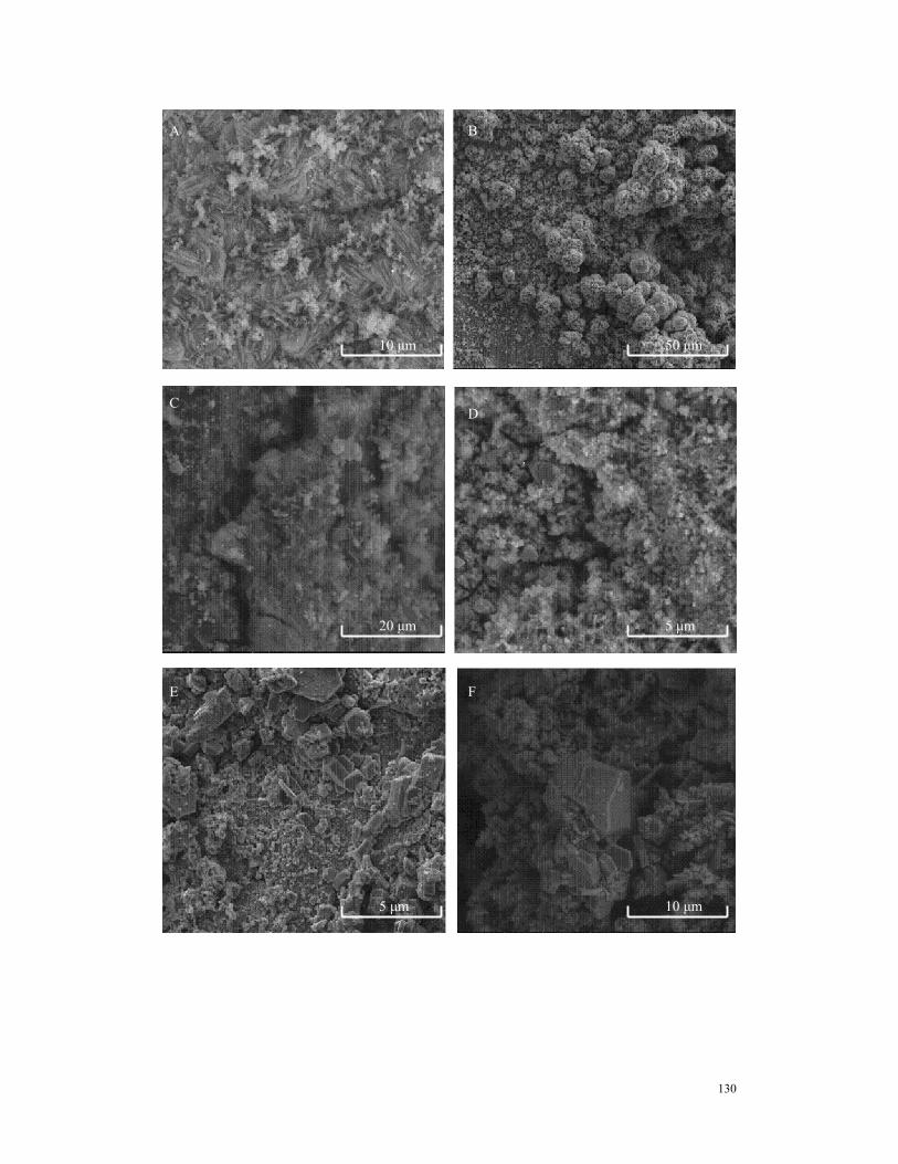
when the column just restarted. The morphology and structure of surface corrosion products on
precorroded steel sheets were studied via scanning electron microscope (SEM), X-ray diffraction
(XRD) and X-ray photoelectron spectroscopy (XPS) method. The results showed that the
morphology of surface corrosion products was highly related to iron release and arsenic removal.
v
Fresh precorroded steel sheets have a uniform surface, while aged precorroded steel sheets
exhibited a heterogeneous surface with some areas covered with thick, porous scales.
Lepidocrocite (γ-FeOOH), humboditine (FeC2O4(H2O)2) and clinoferrosilite (Fe1.5Mg0.5Si2O6) are
the mainly component on the fresh precorroded steel sheet, while goethite (α-FeOOH),
lepidocrocite and magnetite (Fe3O4)are the primary component of the aged precorroded steel sheet
surface. After they were employed in the column for arsenic removal, the primary phase on
precorroded steel sheet changed to goethite and magnetite, calcite was also detected. Arsenic
extracted from precorroded steel in iron columns contain only As(III) when the column was
operated at pH < 7 and had been idled. XAFS study of the GAC in pH 7.5 column indicated the
presence of reduced iron phases such as FeO and green rust, some As(V) has also been reduced to
As(III). Idling the columns for 7 days is promoted a reduction reaction in both the iron and the
GAC columns.
vi
TABLE OF CONTENTS
LIST OF TABLES ...........................................................................................................................ix LIST OF FIGURES ..........................................................................................................................x Acknowledgements........................................................................................................................ xii CHAPTER 1 .....................................................................................................................................1 CHAPTER 2 .....................................................................................................................................5
2.1.5.1.1 Precipitation by Alum.......................................................................12 2.1.5.1.2 Precipitation by Iron.........................................................................12 2.1.5.1.3 Lime softening .................................................................................13
2.1.5.2 Adsorption and Ion exchange reactions ...............................................14 2.1.5.2.1 Adsorption by activated carbon........................................................14 2.1.5.2.2 Adsorption by Activated Alumina ....................................................16 2.1.5.2.3 Adsorption by iron hydroxide/iron oxides........................................17 2.1.5.2.4 Adsorption by zero valent iron (ZVI)...............................................21 2.1.5.2.5 Adsorption by other low cost adsorbents..........................................24 2.1.5.2.6 Adsorption by Iron Based Sorbents..................................................24
2.2 ACTIVATED CARBON ...................................................................................................26 2.2.1 The Physical Characteristics and Surface Chemistry of Activated Carbon............26 2.2.2 Fe loading onto Activated Carbon for Arsenic Removal........................................28
2.2.2.1 Impregnation ...............................................................................................28 2.2.2.2 Precipitation .............................................................................................29 2.2.2.3 With Chelating Agent...............................................................................29
2.3 IRON CORROSION.........................................................................................................30 2.3.1 Corrosion process...................................................................................................30
2.3.1.1 Anaerobic iron corrosion.............................................................................30 2.3.1.2 Iron corrosion with the presence of oxygen or other oxidizer.....................32 2.3.1.3 Reduction of surface corrosion product on Fe0 ........................................33
2.3.2 Corrosion product characterization ........................................................................34 2.3.2.1 Corrosion scales on iron pipes in water distribution systems......................34
vii
2.3.2.2 Corrosion layers on the surface of iron used in contaminant removal ........36 2.3.3 Surface corrosion products and contaminant removal ...........................................39
2.3.3.1 Iron corrosion and contaminant reduction in PRBs ....................................40 2.3.3.2 Iron corrosion and contaminant adsorption in PBRs...................................41
2.4 THE MECHANISMS OF ARSENIC REMOVAL BY IRON BASED SORBENTS.......42 2.4.1 Adsorption of Arsenic by iron oxide/hydroxide—As removal mechanisms..........42 2.4.2 Arsenic removal by ZVI.........................................................................................43
2.4.2.1 Iron corrosion and arsenic removal on ZVI – the process...........................43 2.4.2.2 Rate controlling arsenic removal by ZVI ....................................................44
4.1.1 Background ............................................................................................................76 4.1.2 Arsenic Removal Technology ................................................................................76 4.1.3 pH Effect on Arsenic Removal by ZVI and Iron (hydr)oxides ..............................77 4.1.4 Iron Corrosion and Iron Release ............................................................................77
4.2 MATERIALS AND METHODS....................................................................................79 4.2.1 Materials..............................................................................................................79 4.2.2 Citrate-Fe preloaded carbon................................................................................80 4.2.3 Iron Pre-corrosion ...............................................................................................80 4.2.4 Column tests........................................................................................................80 4.2. 5 Chemical Analysis..............................................................................................82
viii
4.3 RESULTS AND DISCUSSION.....................................................................................84 4.3.1 Arsenic removal with and without precorroded iron..............................................84 4.3.2 pH effect on Arsenic removal.................................................................................87 4.3.3 Idle Effect on Arsenic Removal .............................................................................92 4.3.4 Precorrosion iron amount effect .............................................................................96 4.3.5 Iron release and arsenic removal in iron column – A summary ..........................96
5.1.1 Surface corrosion layer and its effect on contaminant removal ........................ 111 5.1.2 Arsenic – iron redox reaction and As removal by ZVI .....................................112 5.1.3 As release ..........................................................................................................114
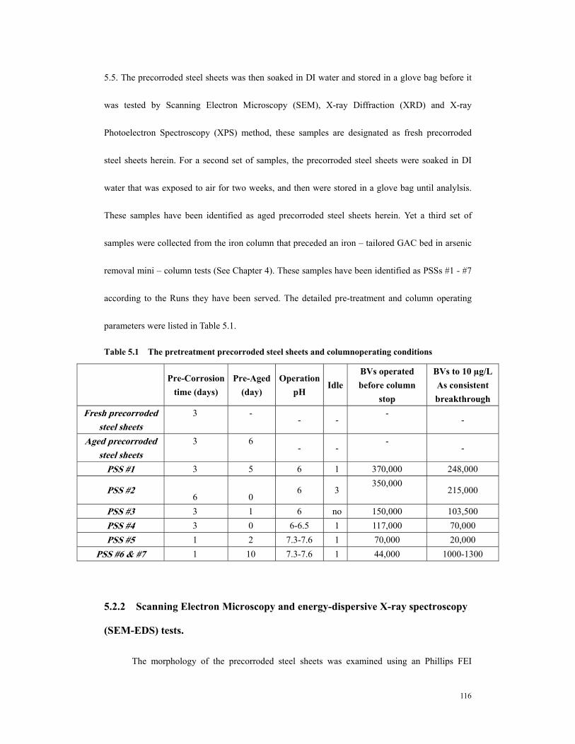
5.2 MATERIALS and METHODS ....................................................................................115 5.2.1 Precorroded steel sheets. ...................................................................................115 5.2.2 Scanning Electron Microscopy and energy-dispersive X-ray spectroscopy (SEM-EDS) tests...........................................................................................................116 5.2.3 X-ray Diffraction (XRD) Measurements. ............................................................117 5.2.4 X-ray Diffraction (XRD) Measurements of the powders collected from PSS surface. ..........................................................................................................................117 5.2.5 X-ray Photoelectron Spectroscopy (XPS) analysis. ..........................................117 5.2.6 Digestion of precorroded steel sheets for arsenic speciation.............................118
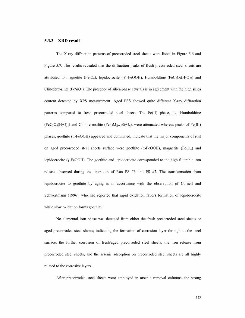
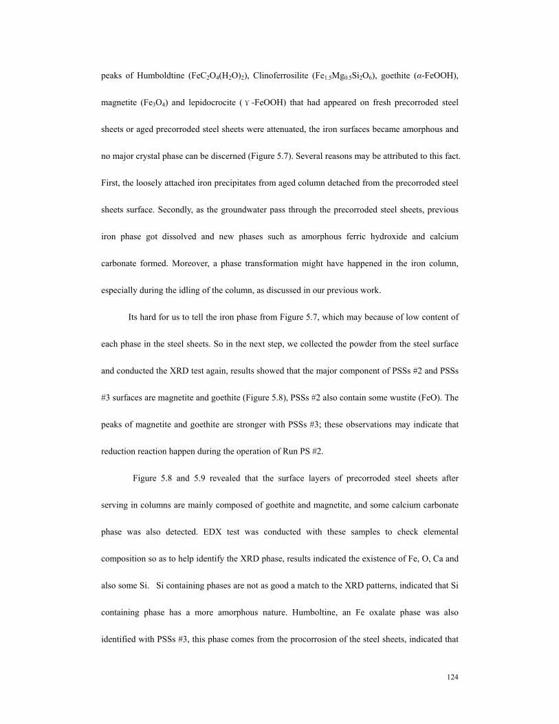
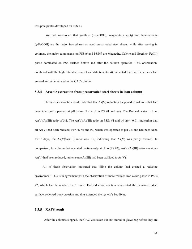
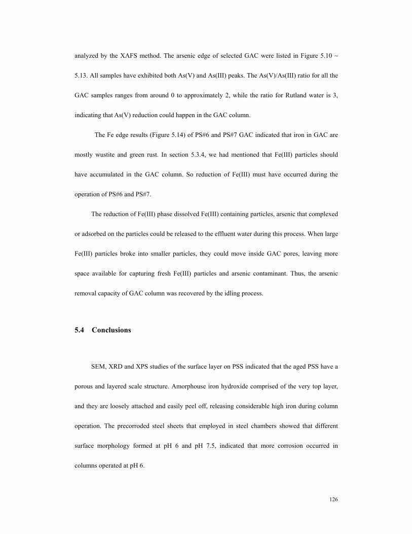
5.3 RESULTS and DISCUSSION....................................................................................118 5.3.1 SEM result............................................................................................................118 5.3.2 XPS results........................................................................................................120 5.3.3 XRD result ........................................................................................................123 5.3.4 Arsenic extraction from precorroded steel sheets in iron column.....................125 5.3.5 XAFS result.......................................................................................................125
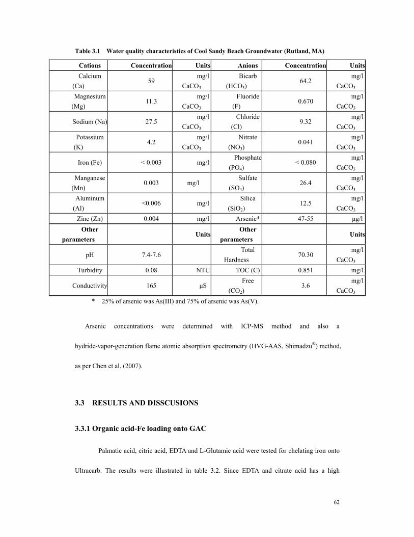
Table 1.1 pKa Values of Arsenate and Arsenite .............................................................10 Table 3.1 Water quality characteristics of Cool Sandy Beach Groundwater (Rutland,
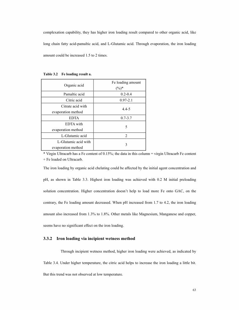
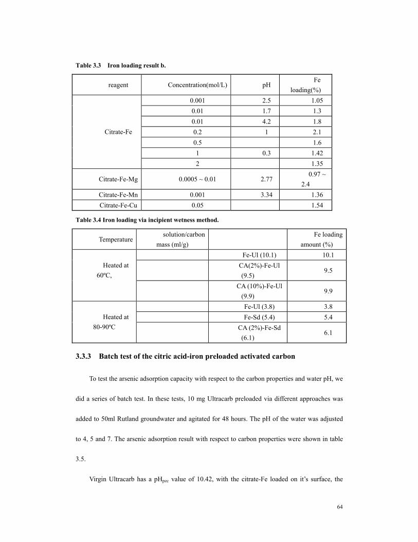
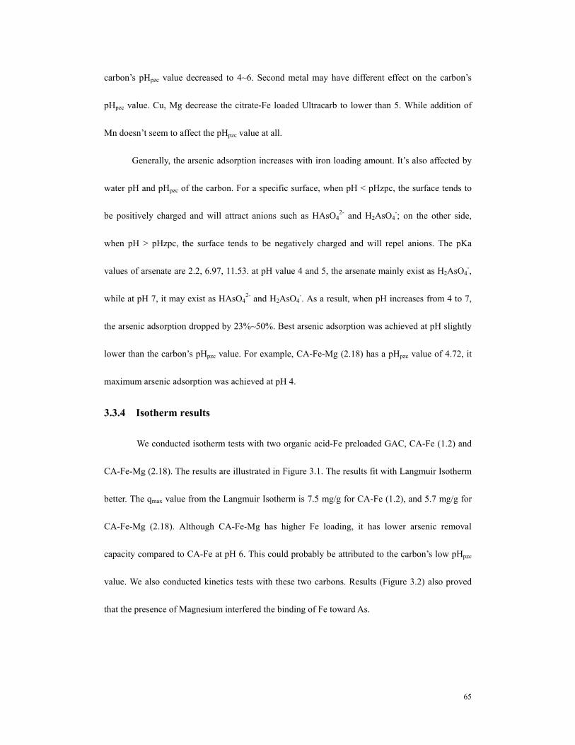
MA).................................................................................................................................62 Table 3.2 Fe loading result a..............................................................................................63 Table 3.3 Iron loading result b. .........................................................................................64 Table 3.4 Iron loading via incipient wetness method. ........................................................64 Table 3.5. Arsenic adsorption capacity with respect to water pH and carbon properties
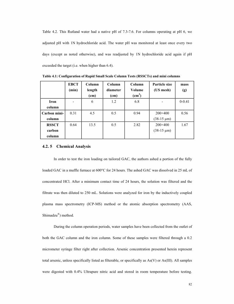
.........................................................................................................................................66 Table 4.1: Configuration of Rapid Small Scale Column Tests (RSSCTs) and mini
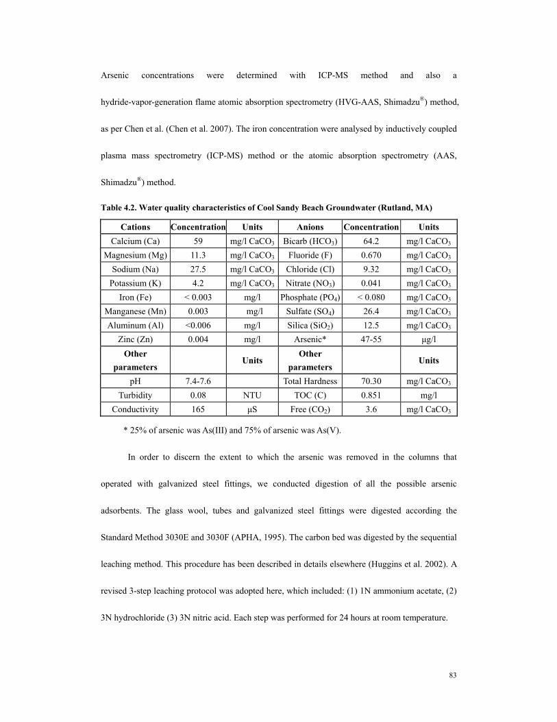
columns...........................................................................................................................82 Table 4.2. Water quality characteristics of Cool Sandy Beach Groundwater (Rutland,
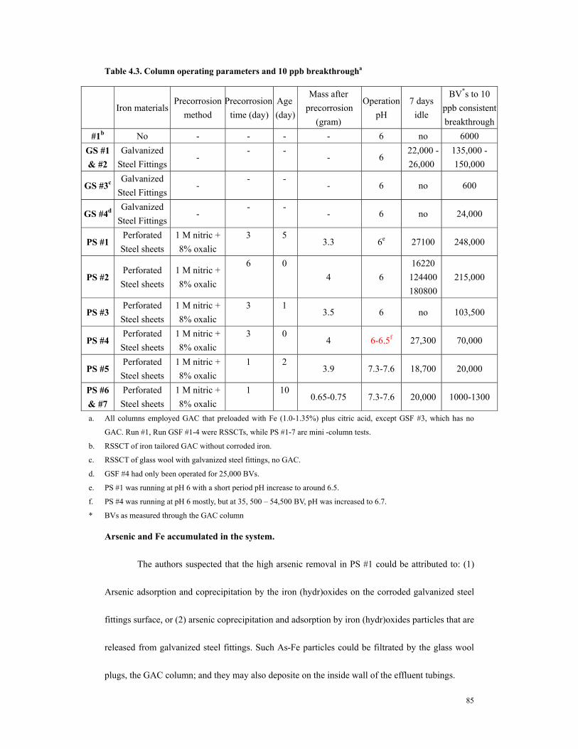
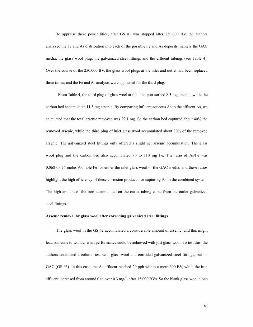
MA).................................................................................................................................83 Table 4.3. Column operating parameters and 10 ppb breakthrougha..............................85 Table 4.4. Arsenic distribution in GS #1 (iron - tailored GAC coupled with corrosion of
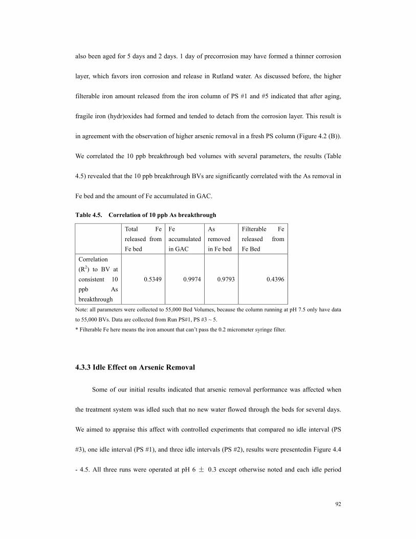
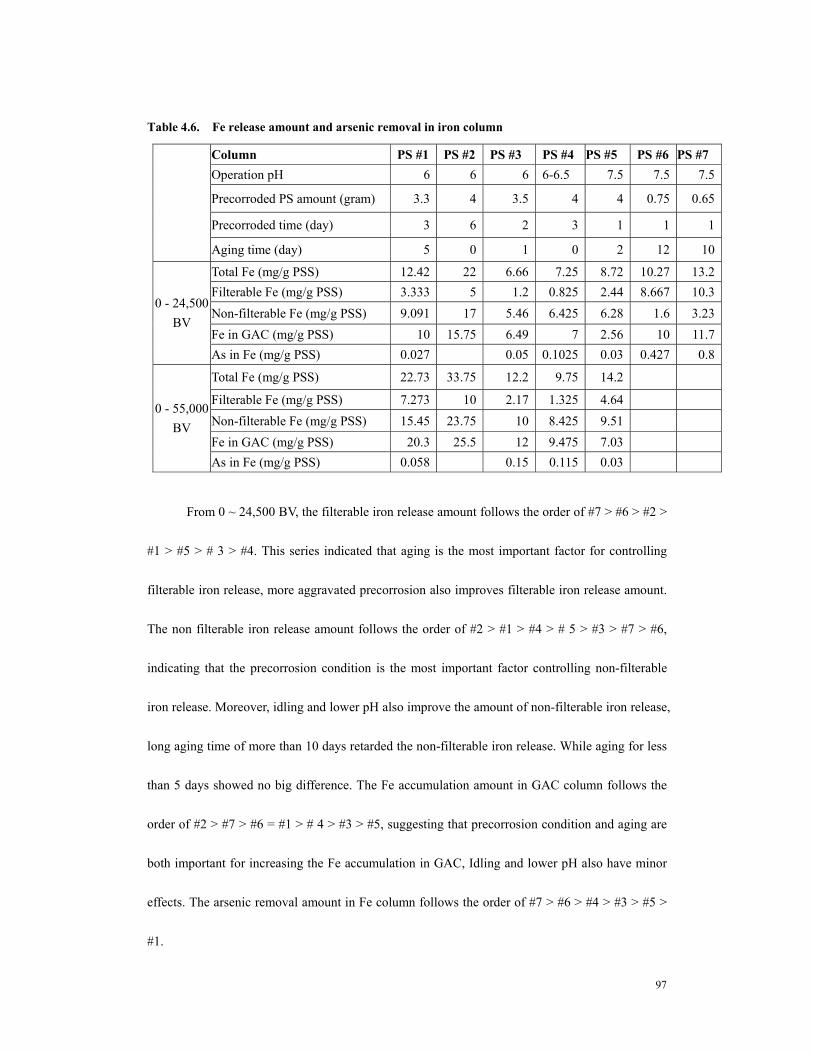
galvanized steel fittings) after 250,000 BV ..................................................................87 Table 4.5. Correlation of 10 ppb As breakthrough..........................................................92 Table 4.6. Fe release amount and arsenic removal in iron column................................97 Table 5.1 The pretreatment precorroded steel sheets and columnoperating conditions
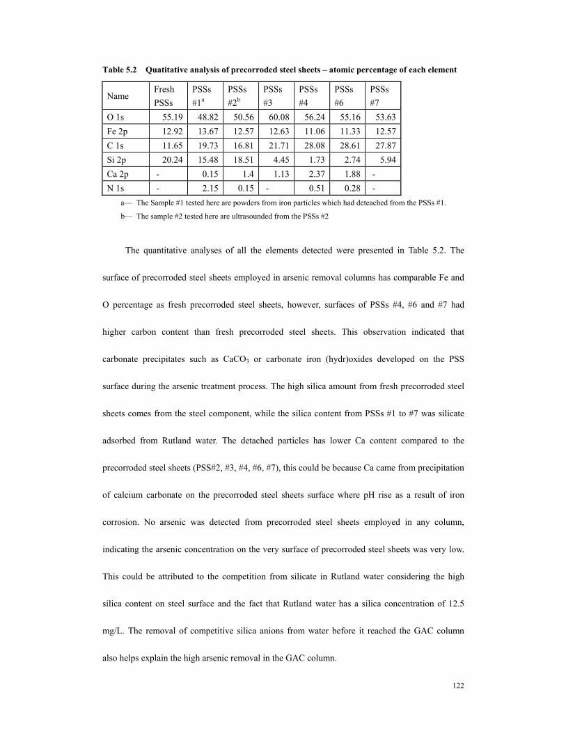
.......................................................................................................................................116 Table 5.2 Quatitative analysis of precorroded steel sheets – atomic percentage of each
element .........................................................................................................................122
x
LIST OF FIGURES
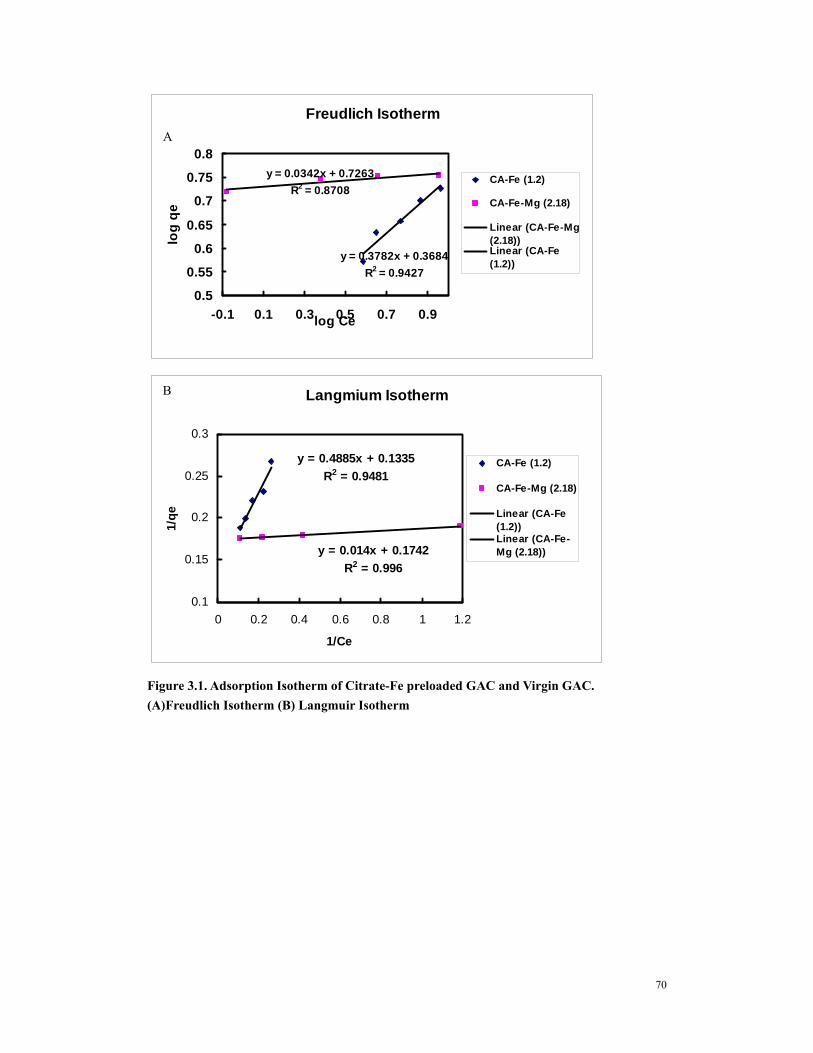
Figure 1.1 Molecular configurations of arsenite and arsenate..........................................55 Figure 1.2 (A) arsenate and (B) arsenite speciation as a function of pH..........................55 Figure 3.1. Adsorption Isotherm of Citrate-Fe preloaded GAC and Virgin GAC.
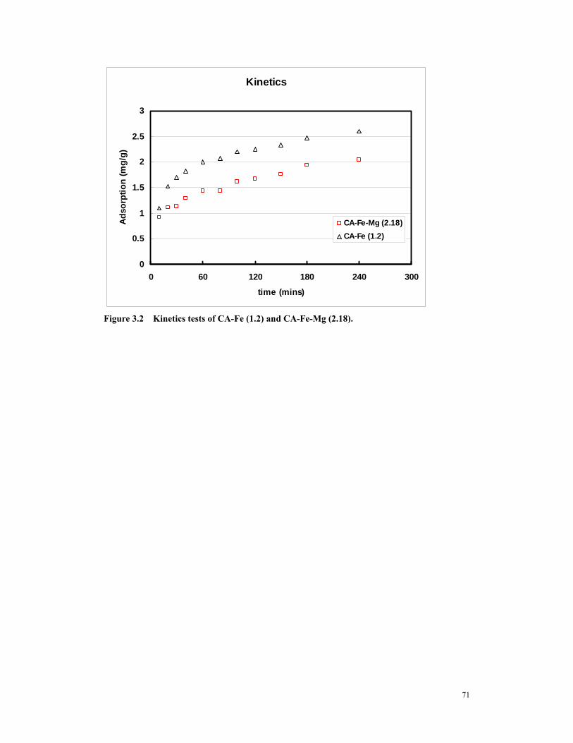
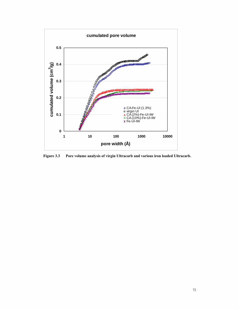
(A)Freudlich Isotherm (B) Langmuir Isotherm .........................................................70 Figure 3.2 Kinetics tests of CA-Fe (1.2) and CA-Fe-Mg (2.18). .....................................71 Figure 3.3 Pore volume analysis of virgin Ultracarb and various iron loaded
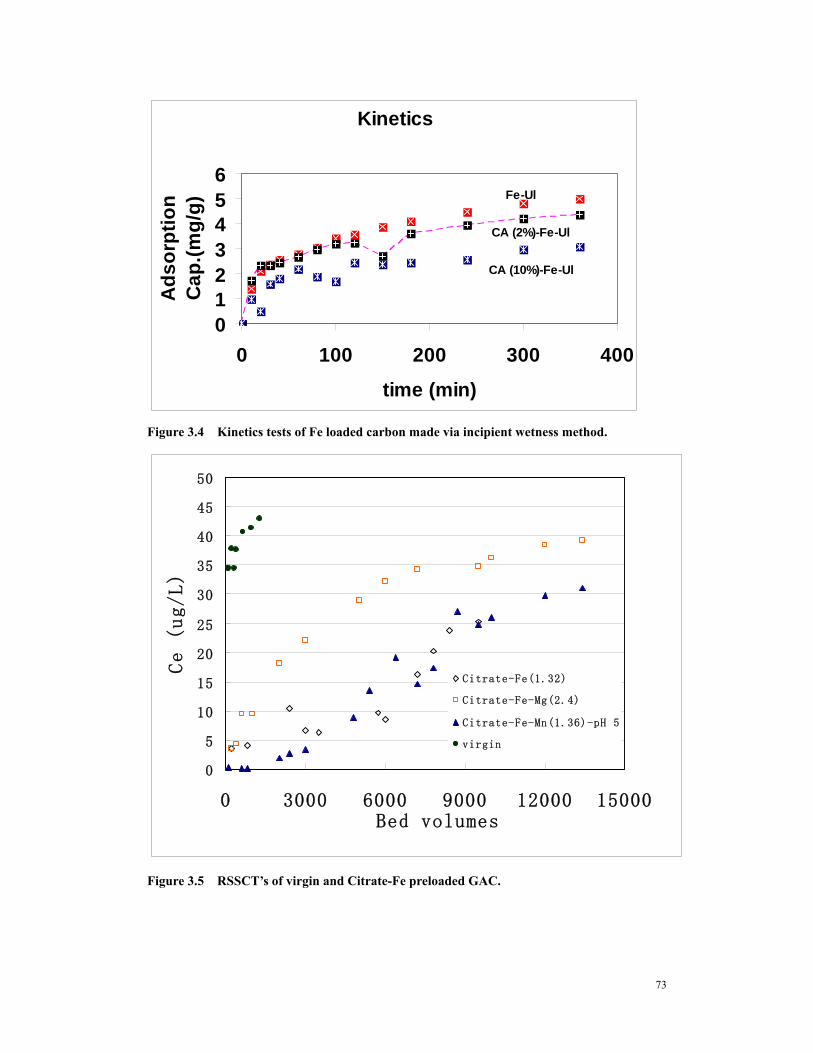
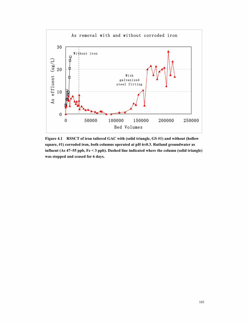
Ultracarb........................................................................................................................72 Figure 3.4 Kinetics tests of Fe loaded carbon made via incipient wetness method. .....73 Figure 3.6 RSSCT’s of amorphous iron oxide preloaded GAC. ....................................74 Figure 4.1 RSSCT of iron tailored GAC with (solid triangle, GS #1) and without
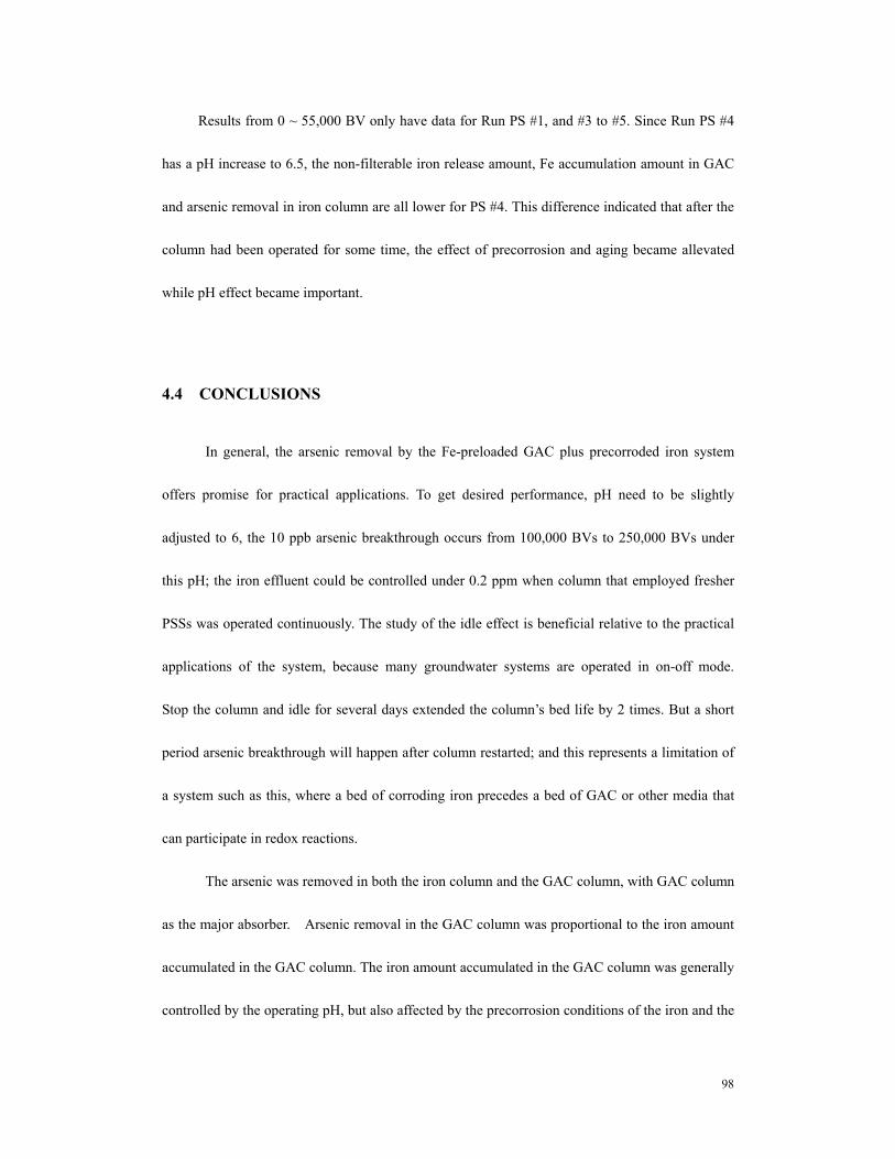
(hollow square, #1) corroded iron, both columns operated at pH 6±0.3. Rutland groundwater as influent (As 47~55 ppb, Fe < 3 ppb). Dashed line indicated where the column (solid triangle) was stopped and ceased for 6 days. ..............................103
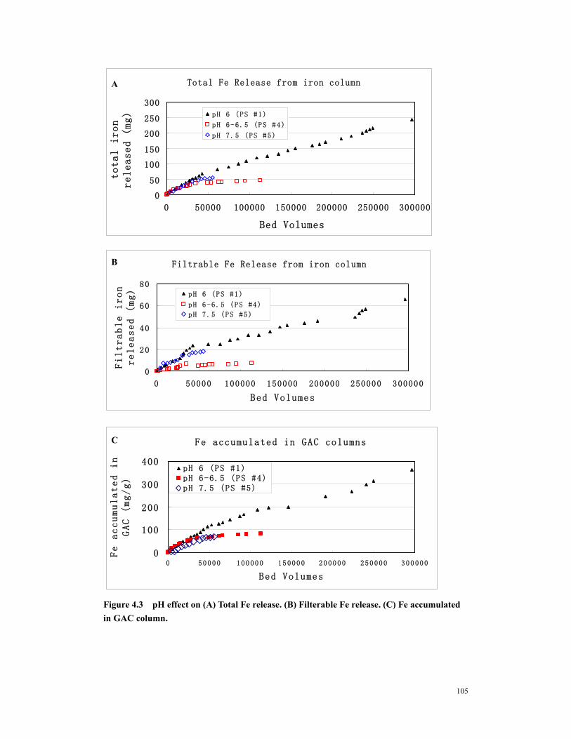
Figure 4.3 pH effect on (A) Total Fe release. (B) Filterable Fe release. (C) Fe accumulated in GAC column. ....................................................................................105
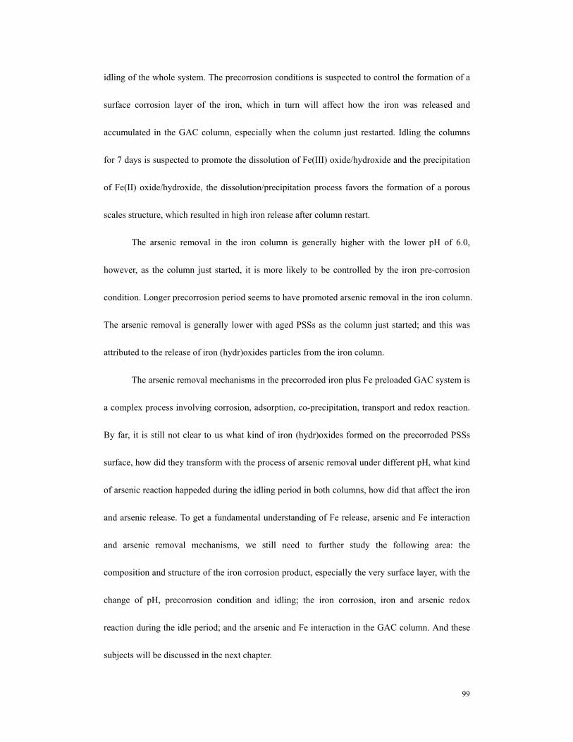
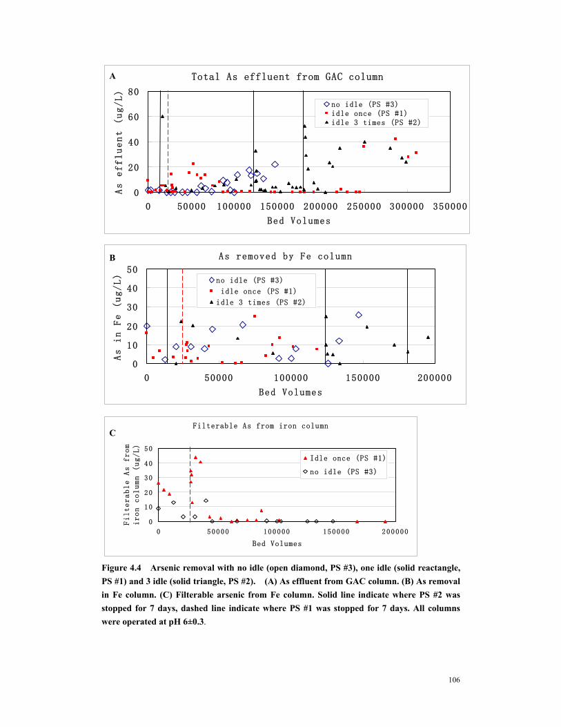
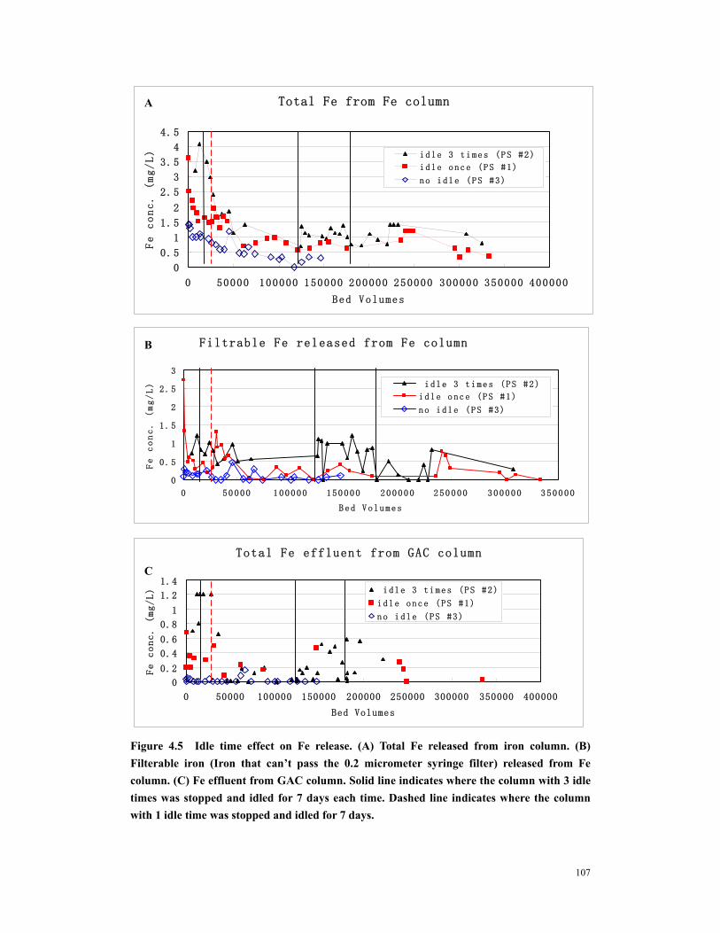
Figure 4.4 Arsenic removal with no idle (open diamond, PS #3), one idle (solid reactangle, PS #1) and 3 idle (solid triangle, PS #2). (A) As effluent from GAC column. (B) As removal in Fe column. (C) Filterable arsenic from Fe column. Solid line indicate where PS #2 was stopped for 7 days, dashed line indicate where PS #1 was stopped for 7 days. All columns were operated at pH 6±0.3 ............................106
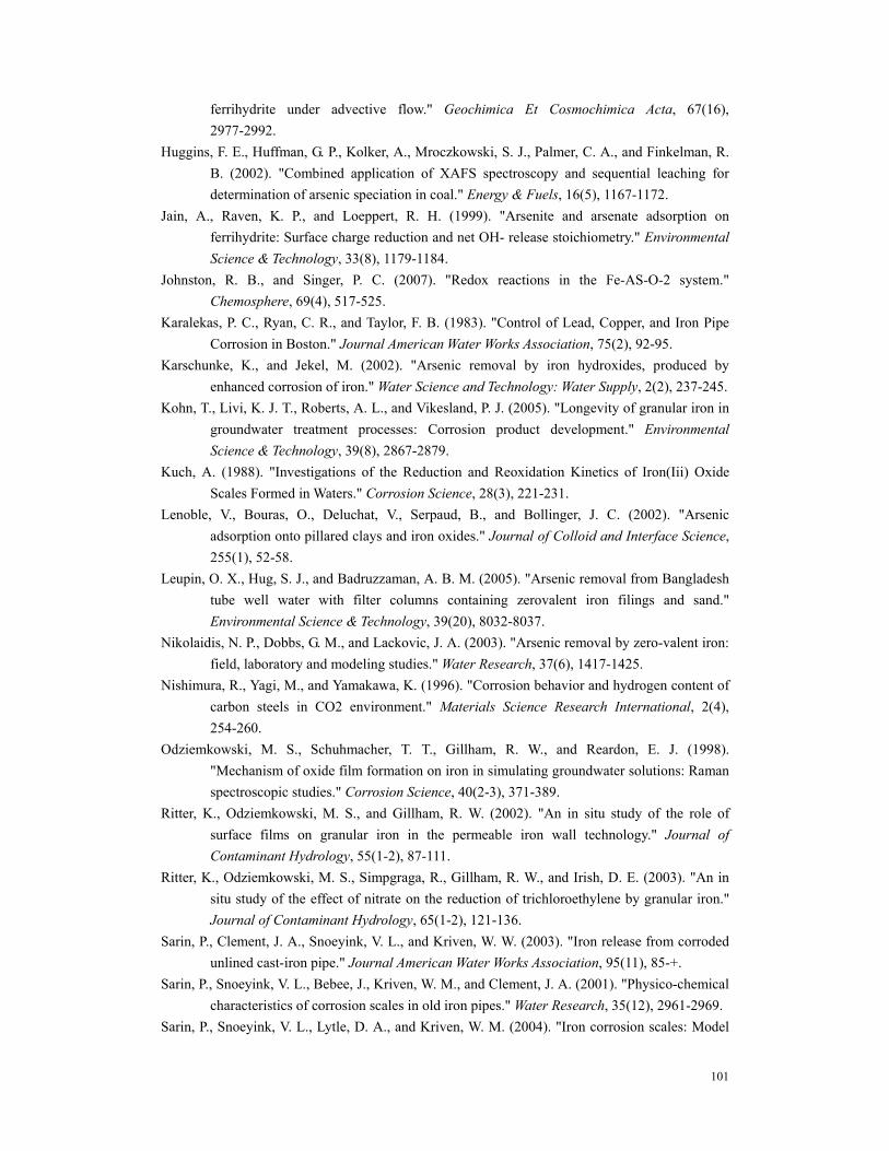
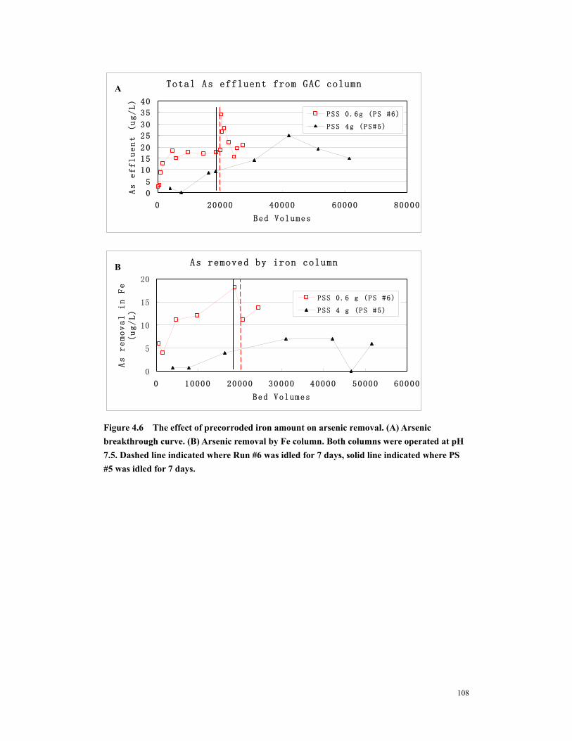
Figure 4.6 The effect of precorroded iron amount on arsenic removal. (A) Arsenic breakthrough curve. (B) Arsenic removal by Fe column. Both columns were operated at pH 7.5. Dashed line indicated where Run #6 was idled for 7 days, solid line indicated where PS #5 was idled for 7 days. ......................................................108
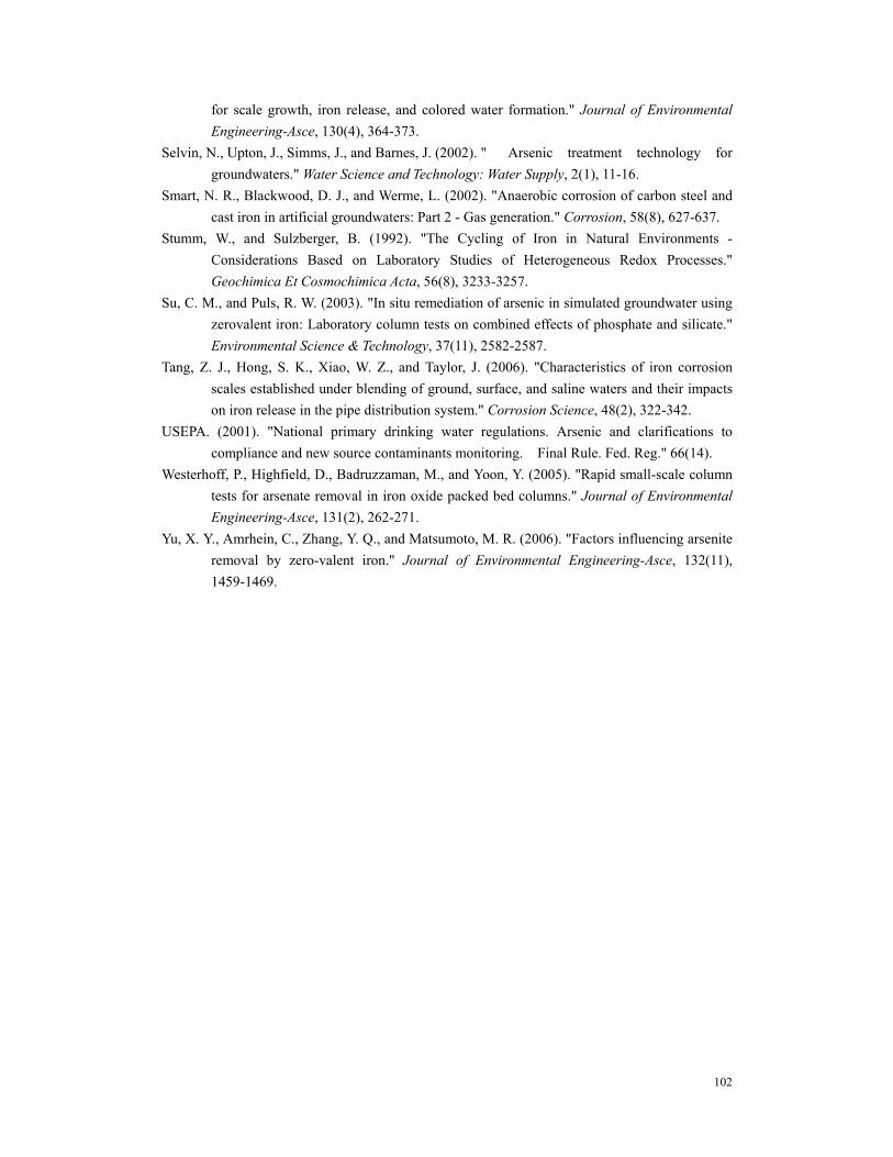
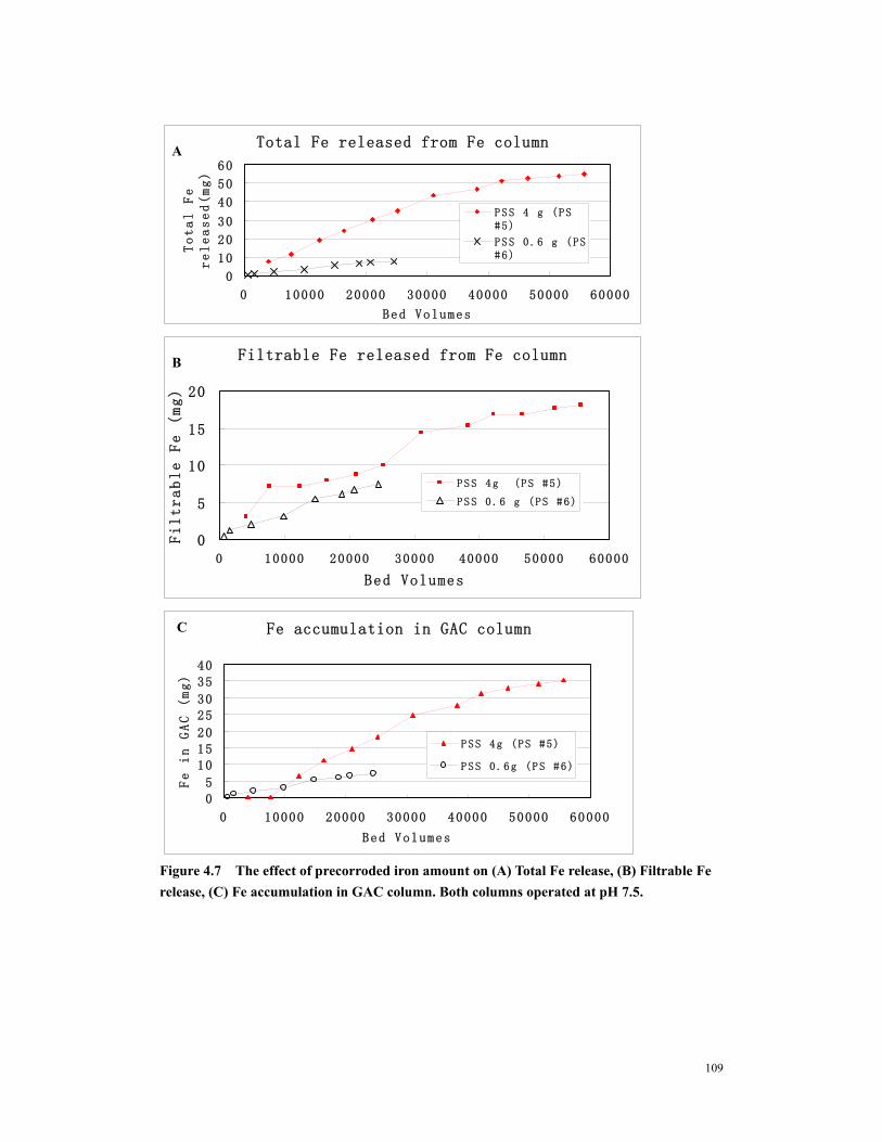
Figure 4.7 The effect of precorroded iron amount on (A) Total Fe release, (B) Filtrable Fe release, (C) Fe accumulation in GAC column. Both columns operated at pH 7.5........................................................................................................................................109
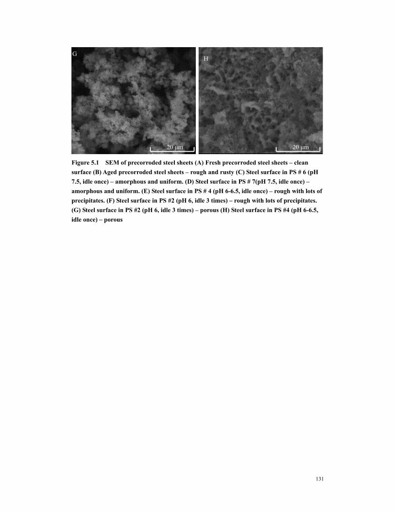
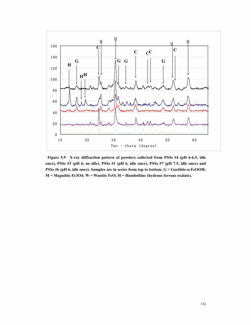
Figure 5.1 SEM of precorroded steel sheets (A) Fresh precorroded steel sheets – clean surface (B) Aged precorroded steel sheets – rough and rusty (C) Steel surface in PS # 6 (pH 7.5, idle once) – amorphous and uniform. (D) Steel surface in PS # 7(pH 7.5, idle once) – amorphous and uniform. (E) Steel surface in PS # 4 (pH 6-6.5, idle once) – rough with lots of precipitates. (F) Steel surface in PS #2 (pH 6, idle 3 times) – rough with lots of precipitates. (G) Steel surface in PS #2 (pH 6, idle 3 times) – porous (H) Steel surface in PS #4 (pH 6-6.5, idle once) – porous ............................131
Figure 5.2 Various crystals on surfaces of PSSs # 2 and PSSs #4. (A) to (E) Iron oxides, (F) Calcium oxides and iron oxides............................................................................132
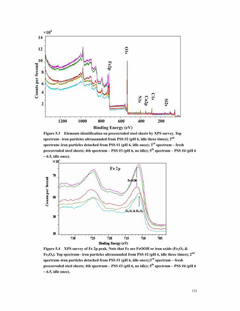
Figure 5.3 Elements identification on precorroded steel sheets by XPS survey. Top spectrum– iron particles ultrasounded from PSS #2 (pH 6, idle three times); 2nd spectrum–iron particles detached from PSS #1 (pH 6, idle once); 3rd spectrum – fresh precorroded steel sheets; 4th spectrum – PSS #3 (pH 6, no idle); 5th spectrum – PSS #4 (pH 6 ~ 6.5, idle once). .................................................................................133
xi
Figure 5.4 XPS survey of Fe 2p peak. Note that Fe are FeOOH or iron oxide (Fe2O3 & Fe3O4). Top spectrum– iron particles ultrasounded from PSS #2 (pH 6, idle three times); 2nd spectrum–iron particles detached from PSS #1 (pH 6, idle once);3rd spectrum – fresh precorroded steel sheets; 4th spectrum – PSS #3 (pH 6, no idle); 5th spectrum – PSS #4 (pH 6 ~ 6.5, idle once)............................................................133
Figure 5.5 XPS survey of O 1s peak. Note that O is mainly hydroxide or iron oxide. 1st spectrum– iron particles ultrasounded from PSS #2 (pH 6, idle three times); 2nd spectrum–iron particles detached from PSS #1 (pH 6, idle once);3rd spectrum – fresh precorroded steel sheets; 4th spectrum – PSS #3 (pH 6, no idle); 5th spectrum – PSS #4 (pH 6 ~ 6.5, idle once). .................................................................................134
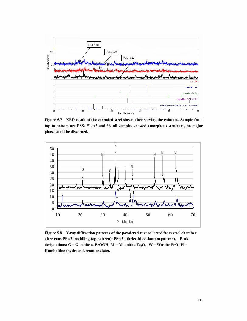
Figure 5.8 X-ray diffraction patterns of the powdered rust collected from steel chamber after runs PS #3 (no idling-top pattern); PS #2 ( thrice-idled-bottom pattern). Peak designations: G = Goethite-α-FeOOH; M = Magnitite Fe3O4; W = Wustite FeO; H = Humboltine (hydrous ferrous oxalate). ......................................135
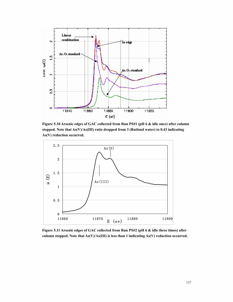
Figure 5.10 Arsenic edges of GAC collected from Run PS#1 (pH 6 & idle once) after column stopped. Note that As(V)/As(III) ratio dropped from 3 (Rutland water) to 0.43 indicating As(V) reduction occurred..................................................................137
Figure 5.11 Arsenic edges of GAC collected from Run PS#2 (pH 6 & idle three times) after column stopped. Note that As(V)/As(III) is less than 1 indicating As(V) reduction occurred. .....................................................................................................137
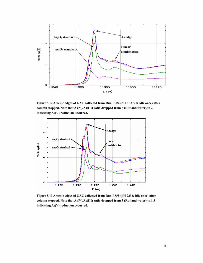
Figure 5.12 Arsenic edges of GAC collected from Run PS#4 (pH 6 ~6.5 & idle once) after column stopped. Note that As(V)/As(III) ratio dropped from 3 (Rutland water) to 2 indicating As(V) reduction occurred. .....................................................138
Figure 5.13 Arsenic edges of GAC collected from Run PS#5 (pH 7.5 & idle once) after column stopped. Note that As(V)/As(III) ratio dropped from 3 (Rutland water) to 1.3 indicating As(V) reduction occurred....................................................................138
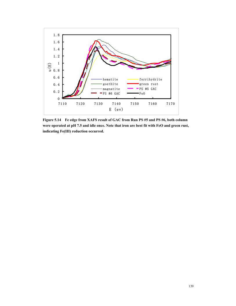
Figure 5.14 Fe edge from XAFS result of GAC from Run PS #5 and PS #6, both column were operated at pH 7.5 and idle once. Note that iron are best fit with FeO and green rust, indicating Fe(III) reduction occurred. ............................................139
xii
Acknowledgements
There are many people who have helped to complete this work, and I owe thanks to all of them.
First and foremost, I would like to express my appreciation to Dr. Fred S. Cannon, for giving me
this opportunity to do this work, and for his guide and support throughout this study. It has been a
pleasure working for him.
I would like to thank Dr. Brian A. Dempsey, Dr. Paul Painter, and Dr. John M. Regan for their
willingness to serve on my doctoral committee.
I would also like to thank Dr. Robert Parette, Dr. Weifang Chen, Fenglong Sun, Dr. Adam Redding,
Dr. Wang Yujue and Huang He for their help with some Laboratory procedure and all the graduate
students and staffs in the Kappe Laboratory for their kindly help.
This study was supported by the American Water Works Association Research Foundation. We
thank Siemens Water Technologies and Cool Sandy Beach Community Water System, Inc.
Rutland, MA for their support and service.
1
CHAPTER 1
INTRODUCTION
Throughout the world, arsenic is creating potentially serious environmental problems for
humans and other living organisms. Most reported arsenic problems are found in groundwater
water supply systems and are caused by natural processes such as mineral weathering and
dissolution resulting from a change in the geo-chemical environment to a reductive condition
(Astrup et al. 2000; Namasivayam and Senthilkumar 1998).
Millions of people in Western Bengal and Bangladesh have been drinking groundwater from
wells that contain 100-2,000 µg/L As, and many of these people have succumbed to diseases that
are caused by the arsenic contaminated ground water (Mandal et al. 1996). In the United States
over 35,000 people may be drinking water contaminated with more than 50 μg/L of arsenic and
over 2.5 million people could be supplied with water having arsenic levels over 25 μg/L (Smith et
al. 1992). Consumption of arsenic at the 50 µg/L level is estimated to cause mortality due to
lung, kidney, or bladder cancer in 1 out of every 1,000 to 10,000 people. Because of this concern,
the WHO in 1993 and USEPA in 2001, lowered the arsenic standard from 50 ppb to 10 ppb; and
the USEPA likewise has dictated that, all United States public water systems must comply with the
new 10 ppb standard as of January 1st 2006. In initial projections, USEPA and AwwaRF had
estimated the costs to meet this MCL to be $102 to 550 million per year (Frey 2000; USEPA
2001).
Modified conventional iron coagulation and filtration can be cost effective arsenic
2
removal for the larger municipalities; but such treatment may not be practical for small and very
small water utilities, which commonly employ simple well head treatment systems. Thus there has
been an urgent need to devise simple arsenic removal systems that are suitable for small utilities.
This research aimed to devise a means to remove arsenic from groundwater in a cost
effective manner for small and very small water systems. Activated carbon has been widely used
in the water treatment industry. The inherently simple features about activated carbon are that
GAC column is easy to operate and very applicable to small and very small water systems.
Studies revealed that iron (III) had high affinity toward inorganic arsenic species and very
selective in the sorption process. Granular ferric hydroxide (GFH) can be effective to remove both
As (V) and As (III) from aqueous solutions, it is physically weak, and will crumble and crush and
lost its capacity during the arsenic removal process. Recent researches are focused on creating
cheap and stable iron bearing adsorbents, such as iron oxide coated sand (Gupta, 2005), Iron oxide
impregnated activated carbon(Vaughan, 2005; Reed, 2000), and GAC based iron containing
adsorbent (Gu, 2005). GAC has large surface area, high pore volume, and rigid structure, which
renders it an ideal backbone for hosting a considerable quantity of iron, the authors aimed to
preload GAC with an effective way so as to improve the GAC’s arsenic removal capacity without
blocking GAC pored with too much unavailable iron.
Zero valent iron (ZVI) has been successfully used as a filter medium to remove arsenic
from water. ZVI’s bed life is not so long compared with GFH, but ZVI is relatively cost effective.
Researchers observed that the ZVI filter easily clogged with the iron oxidation; and to prevent this
clogging, iron filings need to be mixed with sand homogenously, but the homogenously mixed
ZVI/sand filter released effluent iron as high as 70 mg/L (Nikolaidis et al, 2003). Adding a
3
separate sand filter could control the iron effluent to less than 0.3 mg/L (bang, 2005); but this
added to system complexity.
The iron loaded GAC plus precorroded iron could be an effective way of arsenic removing
from groundwater. The precorroded iron could serve as an arsenic remover with its iron
(hydr)oxides corrosion products, it could also provide fresh iron for arsenic removal by adsorption
or coprecipitation in GAC column.
Research Objectives
The objectives of this research were:
1. To extend the bed life of activated carbon for arsenic removal.
2. To test the hypothesis that by preloading organic acid-Fe onto activated carbon surface, even
with just 1.2% Fe loading, the resultant carbon would be more effective in arsenic adsorption.
3. To test the hypothesis that when coupled with precorroded iron source, the iron preloaded
carbons are more effective in removing arsenic.
4. To test the arsenic removal as a function of pH, idle times, aging etc; and to study the influence
of iron release on arsenic removal during the column operation period.
5. To characterize the precorroded steel sheets so as to obtain a better understanding of how the
corrosion surface affect arsenic removal.
6. To test the hypothesis that arsenic removal in the precorroded iron plus iron loaded GAC
system is highly related to iron accumulated in GAC.
7. To study the arsenic and iron speciation in precorroded iron and GAC, so as to
explore the mechanism of arsenic and iron interaction.
4
REFERENCES Astrup, T., Stipp, S. L. S., and Christensen, T. H. (2000). "Immobilization of chromate from coal fly
ash leachate using an attenuating barrier containing zero-valent iron." Environmental Science & Technology, 34(19), 4163-4168.
Frey, M. (2000). " Cost implications of a lower arsenic MCL. Final report." Awwa Research Foundation.
Mandal, B. K., Chowdhury, T. R., Samanta, G., Basu, G. K., Chowdhury, P. P., Chanda, C. R., Lodh, D., Karan, N. K., Dhar, R. K., Tamili, D. K., Das, D., Saha, K. C., and Chakraborti, D. (1996). "Arsenic in groundwater in seven districts of West Bengal, India - The biggest arsenic calamity in the world." Current Science, 70(11), 976-986.
Namasivayam, C., and Senthilkumar, S. (1998). "Removal of Arsenic(V) from Aqueous Solution Using Industrial Solid Waste: Adsorption Rates and Equilibrium Studies." Ind. Eng. Chem. Res., 37, 4816-4822.
USEPA. (2001). "National primary drinking water regulations. Arsenic and clarifications to compliance and new source contaminants monitoring. Final Rule. Fed. Reg." 66(14).
5
CHAPTER 2
LITERATURE REVIEW
2.1 ARSENIC
2.1.1 Background
Throughout the world, arsenic is creating potentially serious environmental problems for
humans and other living organisms. Most reported arsenic problems are found in groundwater
water supply systems and are caused by natural processes such as mineral weathering and
dissolution resulting from a change in the geo-chemical environment to a reductive condition
(Astrup et al. 2000; Namasivayam and Senthilkumar 1998). Arsenic contamination is also
caused by human activities such as mining wastes, petroleum refining, sewage sludge, agricultural
chemicals, ceramic manufacturing industries and coal fly ash (Grossl et al. 1997; Manning
and Goldberg 1997; Viraraghavan et al. 1999).
Millions of people in Western Bengal and Bangladesh have been drinking groundwater
from wells that contain 100-2,000 µg/L As, and many of these people have succumbed to diseases
that are caused by the arsenic contaminated ground water (Mandal et al. 1996). In the United
States over 35,000 people may be drinking water contaminated with more than 50 μg/L of arsenic
and over 2.5 million people could be supplied with water having arsenic levels over 25 μg/L
(Smith et al. 1992). Consumption of arsenic at the 50 µg/L level is estimated to cause mortality
due to lung, kidney, or bladder cancer in 1 out of every 1,000 to 10,000 people. The World
Health Organization (WHO) announced that water containing more than 50 µg/L of arsenic is
unsuitable due to acute and chronic toxicity. Owing to epidemiological evidence linking arsenic
6
and cancer, the safe limit of arsenic in drinking water was reduced from 50 µg/L to 10 µg/L in
1993 by WHO (Johnston and Heijnen 2001; Tokunaga et al. 1999). The Clinton administration
promulgated a new maximum concentration level (MCL) of 10 µg/L As, and the EPA announced
on October 31, 2001 that public water supplies nationwide should reduce arsenic concentration
levels to below 10 µg/L by 2006. Complying with these stringent limits on arsenic could impose
a heavy financial burden on small public water system (Woods 2001). The overall objective of
this research has been to discern a less expensive means of removing arsenic from groundwater,
particularly for small municipalities.
2.1.2 Toxicology
Arsenic in drinking water may cause chronic arsenic intoxication (arsenicosis), which
may lead to harm of respiratory, digestive, renal circulatory, neural systems and internal organs
(ATSDR, 2000; IPCS, WHO, 2001). There are reported clinical effects and symptoms including
Raynaud’s syndrome, hypertension, cerebral infarction (Chen et al. 1995), damage of the
peripheral nerve bodies (Bansal et al. 1991), diabetes mellitus (Chen et al. 1994), and circulatory
disorders. In large regions of Bangladesh and West Benghal, India, the drinking water contains
arsenic concentrations as high as 1 mg/L; and as many as 50-65 million people are being poisoned
by this (Driehaus et al. 1998). In this area, 170,000 people have exhibited symptoms of chronic
arsenicosis(Paty et al. 1995).
The toxicity of arsenic is related to its chemical form and oxidation state. Inorganic
arsenic compounds normally are more toxic than organic compounds. The most significant
consequence of chronic arsenic intoxication is the induction of cancers in various organs.
Therefore, arsenic has been recognized as Class I human carcinogen and is a public concern due to
7
its widespread usage in both industry and agriculture. An area in Taiwan has had drinking water
sources in which arsenic concentrations ranged from 170 to 800 ppb. On the basis of the cancer
that was observed there, Smith et al. (1992) surmised that a 50 ppb arsenic level would translate to
a lifetime risk that 13 people per 1000 could die from cancer to the liver, lung, kidney, or bladder.
Arsenic also causes skin cancer at low concentrations; and it poisons the heart and gastrointestinal
tract at high concentrations.
Inorganic arsenic in low and micro molar doses can cause great genotoxicity. Sodium arsenite
is reported to induce chromosome aberrations, sister chromatic exchanges, and DNA-protein crosslinks
(Dong and Luo 1993).
2.1.3 Regulatory
Arsenic exceeds 10 ppb in at least 4000 community and non-community wells that
appear in more than 45 U.S. states (Frey and Edwards 1997). Half of all the states in America
have more than ten community wells that exceed this new limit; and they are (from roughly west
to east): Alaska, California, Oregon, Washington, Nevada, Idaho, Montana, Utah, Arizona, New
Mexico, Colorado, Texas, Oklahoma, Nebraska, South Dakota, North Dakota, Minnesota,
Wisconsin, Michigan, Indiana, West Virginia, New Jersey, Massachusetts, Vermont, Maine, and
Florida. (http://co.water.usgs.gov/trace/pubs/geo_v46n11/fig1.html; Welch et al. 2000). Many of
these wells service small and very small community water systems; and for the majority of these,
an arsenic removal facility will represent the first treatment system that the small providers have
had to install, above mere chlorination.
In early 2001, the USEPA published a revised arsenic standard of 10 ppb in drinking
water. This is considerably lower than the previous 50 ppb standard, which was established in
8
1942. All public water systems must comply with this 10 ppb standard within 5 years after this
rule was published (i.e. by 2006). The USEPA estimates that 3,000 community water systems
will need to take measures to lower their arsenic levels. The USEPA projects that throughout the
nation, it will cost these communities a cumulative $195-$675 million to comply; and this will
translate to $58-327 / household / year. Other individuals have projected yet higher compliance
costs. The cost burden for removing arsenic will be greatest on very small community systems,
which have traditionally employed no treatment beyond simple chlorination. Thus, there is great
need to devise new and innovative technologies that are inexpensive to use, easy to operate, and
durable through long-term use.
2.1.4 Chemistry of Arsenic
2.1.4.1 Immobilization of arsenic
Arsenic is of concern in water treatment because of its health effects. In general,
inorganic arsenic compounds are more toxic than organic arsenic compounds, and arsenite
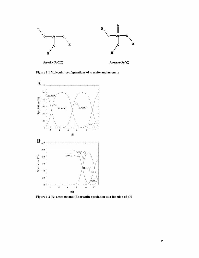
(As(III)) is more toxic than arsenate (As(V)). The molecular structure of both arsenate and arsenite
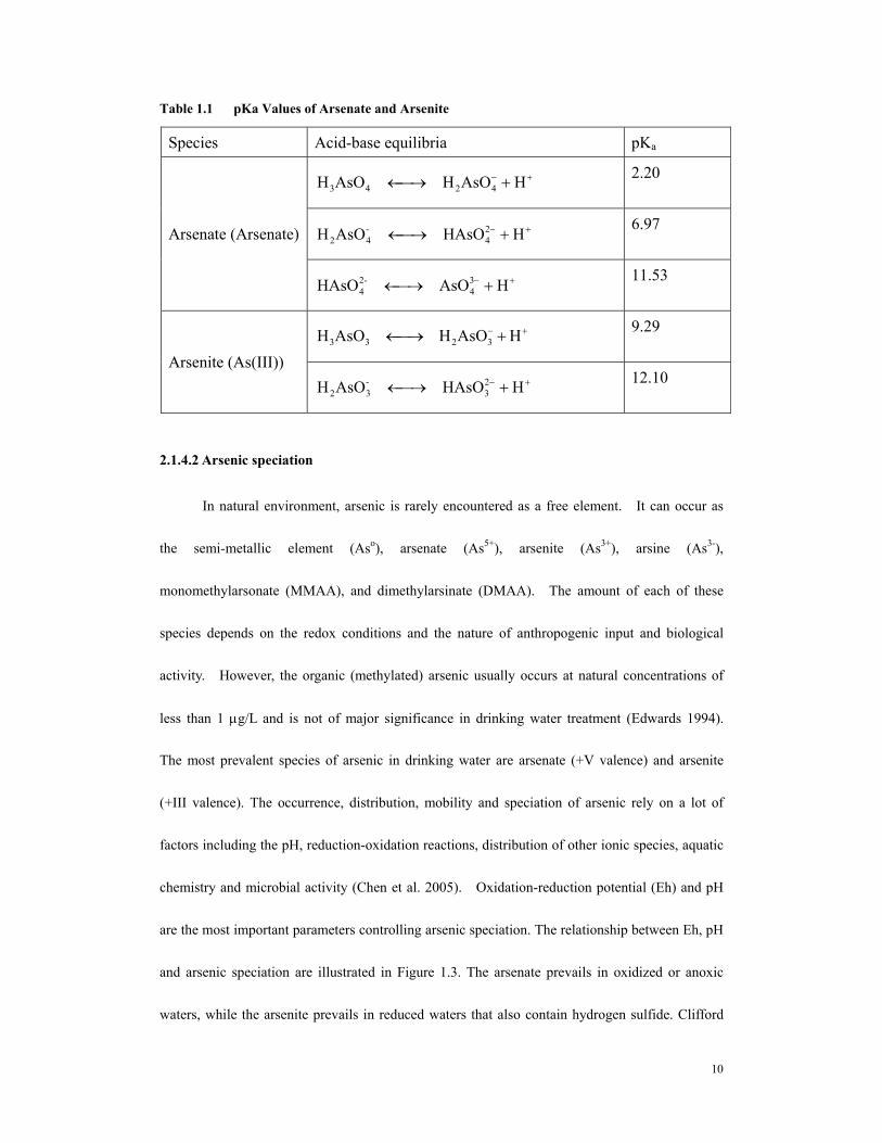
are shown in Figure 1.1. The double-bonded oxygen in arsenate has a large effect on the ionization
due to the loss of hydrogen ions. The tendency of ionization is expressed by pKa (the
dissociation constant). For arsenic species, acid-base equilibria and pKa values are summerized
in Table 1.1. Figure 1.2 shows a schematic of the pH relationship between arsenic species and
illustrates the significant difference in the pH values of ionization steps that occur between
arsenate and arsenite. The pE-pH relationship is important for understanding the mobility of
arsenic species in groundwater and the effectiveness of arsenic treatment systems (Sun and Doner
9
1998). Inorganic arsenic species mainly exist in the +3 or +5 oxidation state. These oxidation
states are controlled by micro-organisms, redox potential, and pH, as well as reactions with other
chemical compounds in the soil and sediments such as iron sulfides, iron/manganese/aluminum
oxides and hydroxides, dissolved organic matter, etc. (Loeppert et al. 1995).
Components of soils and sediments are involved with ionic species in two types of adsorptive
reactions. The first type of adsorption reaction is based on ion exchange between charged
adsorptive sites and charged soluble ions. The second type is London Van der Waals bonding
and is the result of complex interactions between the electron clouds of molecules, molecular
polarity, and the attractive forces of an atomic nucleus for electrons beyond its own electron cloud.
The change of groundwater to a reductive condition could cause the arsenate attached in the soil or
sediment to be released into the liquid phase due to the chemical reduction of arsenate to arsenite
(especially predominant species H3AsO3 at below pH 9.22), which is more mobile due to its weak
adsorption on most mineral surfaces (Manning and Goldberg 1997; Scott 1991). The redox
alterations incurred when drawing reduced groundwater out of the ground can increase the arsenic
levels in the extracted water.
10
Table 1.1 pKa Values of Arsenate and Arsenite
Species Acid-base equilibria pKa
+− +⎯→← HAsOHAsOH 4243 2.20
+− +⎯→← HHAsOAsOH 24
-42
6.97 Arsenate (Arsenate)
+− +⎯→← HAsOHAsO 34
-24
11.53
+− +⎯→← HAsOHAsOH 3233 9.29
Arsenite (As(III)) +− +⎯→← HHAsOAsOH 2
3-32
12.10
2.1.4.2 Arsenic speciation
In natural environment, arsenic is rarely encountered as a free element. It can occur as
the semi-metallic element (Aso), arsenate (As5+), arsenite (As3+), arsine (As3-),
monomethylarsonate (MMAA), and dimethylarsinate (DMAA). The amount of each of these
species depends on the redox conditions and the nature of anthropogenic input and biological
activity. However, the organic (methylated) arsenic usually occurs at natural concentrations of
less than 1 μg/L and is not of major significance in drinking water treatment (Edwards 1994).
The most prevalent species of arsenic in drinking water are arsenate (+V valence) and arsenite
(+III valence). The occurrence, distribution, mobility and speciation of arsenic rely on a lot of
factors including the pH, reduction-oxidation reactions, distribution of other ionic species, aquatic
chemistry and microbial activity (Chen et al. 2005). Oxidation-reduction potential (Eh) and pH
are the most important parameters controlling arsenic speciation. The relationship between Eh, pH
and arsenic speciation are illustrated in Figure 1.3. The arsenate prevails in oxidized or anoxic
waters, while the arsenite prevails in reduced waters that also contain hydrogen sulfide. Clifford
11
and Ghurye (2000) compiled data indicating that arsenate represented more than 80% of the
arsenic species in the wells that were tested in California, New Mexico, Arizona, Taiwan, and
Chile; while arsenite predominated in Bangladesh, West Bengal, and Alaska wells. The acid/base
species of arsenate (V) are H3AsO4, H2AsO4-. HAsO4
2-, and AsO43-with corresponding pKa’s of
2.35, 6.75, and 11.6. This means that when the water pH is between 2.35 and 6.75, the H2AsO4-
species will prevail; and when the water pH is between 6.75 and 11.6, the HAsO42-
species will
prevail. Since both of these species that predominate in the near-neutral pH region are charged,
charge-based processes will remove arsenate. Moreover, when the pH is above neutral, the
arsenate exchange bonding will be greater (with the double negative charge) than below neutral
(with the single negative charge).
Similarly, the acid/base species of arsenite (III) are H3AsO3, H2AsO3-, HAsO3
2-, and AsO33-,
with pKa’s of 9.23, 12.11, and 13.41. This means that below pH 9.23, the non-charged H3AsO3
species will predominate, and charge-based processes will not remove arsenite. However, Ghurye
and Clifford (2000) observed that arsenite will oxidize to arsenate when it is exposed to chlorine
for one minute; while dosing with just three times the stoichiometrically required level of chlorine.
This means that in typical groundwaters, a chlorine dose of <0.1 mg/L would convert all arsenite
to arsenate. Most groundwater-based municipalities already have adopted chlorination; and thus
oxidation of As(III) to As(V) will not be an additional issue.
The material that is used in iron walls is not pure iron, but rather is a commercial product,
consisting of scrap metal, mostly cast iron and low alloy steels, and the material is furthermore
covered with a passive oxide film (Ritter et al. 2002). Roh, et al, (2000) studied the master builder
Fe0 filings used for dechlorination with SEM micrograph, results also proved that the Fe was
covered with Fe (hydr)oxides.
Several potential precipitates, such as magnetite (Fe3O4) (Gregory et al. 2004; Lee et al.
2002; Sivavec and Horney 1996) and green rust (e.g., [Fe42+Fe2
3+(OH)12][CO3·2H2O]) (Erbs et
41
al. 1999), as well as Fe2+ adsorbed onto iron (hydr)oxides (Elsner et al. 2004; Klausen et al. 1995;
Pecher et al. 2002), have been shown to be able to reduce organic redox-active contaminants.
Legrand et al. (2004), studied the reduction of chromate by Fe(II)/Fe(III) Carbonate Green Rust.
Results indicate the formation of ferric oxyhydroxy carbonate and the concomitant precipitation of
CrIII monolayers at the surface of the iron compound that induce passivation effects and
progressive rate limitations. Thick green rust particles formed by the corrosion of iron in
permeable reactive barriers, makes FeII not accessible for efficient CrVI removal.
Stratmann et al. (1994) studied the mechanism of the oxygen reduction on rust-covered
metal, the results show that oxygen is predominantly reduced within the rust scale and not at the
metal/electrolyte phase boundary. In order to allow any oxygen reduction, the rust layers have to
be reduced. Oxidized rust scales, which are nearly free of Fe2+ states, inhibit the reduction of
oxygen completely.
The degradation characteristics changes with time in the PBR, these changes are attributed
to (1) reduction in Fe surface reactivity caused by passivation of Fe0 by precipitates, including Fe
(hydr)oxides and Fe sulfides, and (2) alternation of flow paths through Fe filings as a result of
precipitation and cementation.
Bacteria may cause a potential negative consequence of biofouling because the proliferation
of bacteria in an improperly designed reactive barrier could reduce the hydraulic conductivity of
the barrier, thereby hindering the flow of groundwater through it (Weathers and others 1997).
2.3.3.2 Iron corrosion and contaminant adsorption in PBRs
Furukawa, 2002 studied the fine-grained fractions of permeable reactive barrier (PRB)
42
samples for groundwater treatment. They claimed that if adsorption is mechanism for contaminant
removal, Fe0-PRBs may remain effective for a longer period of time in slightly oxidized
groundwater systems where ferrihydrite formation occurs compared to oxygen-depleted systems
where magnetite passivation occurs.
2.4 THE MECHANISMS OF ARSENIC REMOVAL BY IRON BASED
SORBENTS
2.4.1 Adsorption of Arsenic by iron oxide/hydroxide—As removal mechanisms
The mechanisms of As sorption to the iron oxide/hydroxide surfaces based on the
spectroscopic, sorption, and EM measurements are as follows: arsenate forms inner-sphere surface
complexes on Fe oxide, while arsenite forms both inner- and outer-sphere surface complexes on
amorphous Fe oxide (Goldberg and Johnston 2001). Adsorption on ferrihydrite occurs by ligand
exchange of the As species for OH2 and OH− in the coordination spheres of surface structural Fe
atoms (Jain et al. 1999). While arsenate adsorption resulted in the net release of OH− at pH 4.6 and
9.2, arsenite adsorption resulted in net OH− release at pH 9.2 and net H+ release at pH 4.6. The
amount of H+ or OH− released/adsorbed As (mol/L) varied with the As surface coverage,
indicating that different mechanisms of arsenic adsorption predominate at low versus high
coverage. The results provide evidence that during arsenite adsorption at low pH, i.e., pH 4.6, the
oxygen of the Fe–O–As bond remained partially protonated as Fe–O(H)–As (Jain et al. 1999).
For Fe3O4, α-FeOOH, γ -Fe2O3, and amorphous Fe(OH)3, values of pHzpc = 6.5–8.5 were
obtained (Stumm, 1981). Hlavay et al.(2005) studied the surface properties of iron
hydroxide-coated alumina adsorbents for arsenic removal, results revealed that: the total capacity
43
of the adsorbent was 0.12 mmol/g, and the pH of zero point of charge, pHzpc = 6.9 ± 0.3.
Depending on the pH of solutions, the adsorbent can be used for binding of both anions and
cations, if pHeq < pHzpc anions are sorbed on the surface of adsorbent (S) through c and {S–OH}
groups. Values of pHiep = 6.1 ± 0.3 for As(III) and pHiep = 8.0 ± 0.3 for As(V) ions were found.
The amount of surface charged groups (Q) was about zero within the a pH range of 6.5–8.6, due to
the practically neutral surface formed on the adsorption of As(V) ions. At acidic pH (pH 4.7), Q =
0.19 mol/kg was obtained.
2.4.2 Arsenic removal by ZVI
The use of Fe0 to remove arsenic has been actively investigated by many groups t al. (Farrell
et al. 2001; Krishna et al. 2001; Manning et al. 2002; Su and Puls 2001a; Su and Puls 2003). In
this method, arsenic is adsorbed onto corrosion products of zero-valent iron (ZVI) as the ZVI
converts so such species as iron (oxyhydr) oxide. Possible arsenic removal processes in
zero-valent iron system include surface adsorption onto corrosion products, e.g. iron
(oxyhydr)oxides (Manning et al. 2002, Dixit and Hering 2003), precipitation such as formation of
symplesite (Fe3(AsO4)2· 8H2O) (Nikolaidis et al 2003) , co-precipiration ( e.g. arsenic
co-precipitation with carbonate green rust) (Lien and Wilkin 2005) or redox reaction such as As
(III) oxidized to As(V) by corrosion products or impurities such as MnO2 (Melitas et al. 2002,
Manning et al. 2002).
2.4.2.1 Iron corrosion and arsenic removal on ZVI – the process
In anoxic environment, upon contact with water, the corrosion of ZVI may happen as an
autoreduction process, as discussed in Section 2.3.1.3. Continual corrosion of ZVI to generate iron
44
oxides is needed for the continuous removal of As by ZVI. It is expected that, once the free iron
metal is depleted or complete passivation occurs, As removal capacity will decrease and
eventually cease.
With respect to pH, an optimum range for As(III) adsorption by ZVI is expected because: (1)
acidic conditions favor ZVI corrosion; and (2) maximum adsorption of As(III) on iron oxides
occurs between pH 7 and 9.2. ZVI corrosion results in the release of Fe2+ and OH− into solution,
which in turn forms Fe(OH)2 initially and ferric oxides with time. The optimum pH range for
removal of As(III) was found to be between 7 and 8 (Yu et al. 2006).
Aging maybe beneficial for arsenic removal. It was observed that after aging ZVI for two
months, significant improvement was observed in the percentage removal of As(III) at pH 9 (Yu
et al. 2006).
Carbonate effect on arsenite removal by ZVI debatable. Carbonates are known to stimulate
iron corrosion (Evans 1982) however, they may also interfere with As(III) adsorption onto iron
oxides. A recent assertion by Kim et al. (2000) was that complexation between carbonate and As
was responsible for the observed correlation between soluble As with carbonate concentration in a
Michigan groundwater. Yu et al. (2006) found that in typical groundwater conditions, when
alkalinity is below 200 mg/L as CaCO3, competition of HCO3−/CO3
2− with As(III) for adsorption
sites on iron oxides will most likely be negligible.
2.4.2.2 Rate controlling arsenic removal by ZVI
Mass transfer efficiency was found to play an important role in the removal of arsenic by
ZVI. After an initial period of arsenic rapid adsorption to surface rusts formed during
manufacturing and exposure to air, arsenic removal rate is most likely controlled by the rate of
45
iron corrosion and the diffusion of arsenic to adsorption sites in ZVI/iron oxides (Yu, 2006). In a
batch study of As(V) adsorption to ferrihydrite, Fuller et al. (1993) reported that, following the
fast saturation of available surface sites, diffusion of As(V)to inner adsorption sites was the
rate-limiting step.
Liu’s research (2006) has proposed differences in iron aging effect on TCE removal by Fe0
in column and batch results. As reported, long term column tests, decline in dechlorination. The
decline was attributed to an increase in the mass transfer resistance of contaminants due to
insoluble Fe-oxides and Fe-(oxy)- hydroxides formed on particle surface, or to porosity loss and
decreased access to iron particles in the column. In contrast, long-term batch studies on the
corrosion behavior of micrometer-scale iron filings in unbuffered water reported a constant
(zero-order) H2 corrosion rate over a 125-160 day period suggesting that the iron corrosion rate,
hence reactivity, is not changing as the iron ages (Reardon 1995; Reardon 2005).
2.4.3 Redox reaction in ZVI system
The issue of arsenic redox reactions in iron filter media has not been resolved. Several
investigations using column reactors packed with iron filings have reported that the relative
concentrations of As(V) to As(III) in the effluent solutions were the same as those in the feed
solutions (Lackovic et al. 2000; Melitas et al. 2002). Spectroscopic analyses of iron filings from
column reactors treating As(V) have found no discernible As(III) or As(0) associated with the iron
particles, even after more than 1 year of operation (Farrell et al. 2001). These observations suggest
that there is no reduction of As(V) in iron media filters. Although column studies have not
observed changes in the arsenic oxidation state, reduction of As(V) to As(III) and As(III) to As(0)
46
have been observed in batch experiments conducted in nitrogen purged solutions containing iron
filings (Bang et al. 2005). Su and Puls reported that the ratio of As(V) to As(III) on iron filings
after 60 days elapsed was approximately 1:3. This ratio was independent of whether As(V) or
As(III) was the initial reactant, which strongly suggests that the 1:3 ratio is representative of
equilibrium between As(V) and As(III) on the iron surfaces.
Melitas’ study (2002) showed that bound arsenic species decrease the corrosion rate of
zerovalent iron and that bound or solution-phase As(V) may be reduced to As(III). Reduction of
bound As(V) occurs at higher potentials than reduction of aqueous arsenate. At lower potential
that favors the arsenate reduction, the electrochemical adsorption of arsenate was retarted because
of the negatively charged iron surface. Thus As(III) adsorption was favored over As(V) at the iron
surface. The stronger binding of As(III) results in an elevated As(III) to As(V) ratio on the iron
surface with respect to their bulk solution ratio. The elevated As(III) concentrations on the iron
surface decrease the equilibrium potential for further As(V) reduction. Melitas et al. (2002)
concluded that the pH and potential conditions necessary for significant As(V) reduction will be
difficult or impossible to achieve in an open system under freely corroding conditions. Therefore,
in the absence of biological reduction, there will be little conversion of As(V) to As(III) in zero
valent iron filter media.
2.4.4 Arsenic release
The principal mechanisms of arsenic mobilization associated with geochemical conditions
have been identified as desorption in alkaline conditions, competitive sorption, and reductive
release, especially as associated with the dissolution of iron oxides. Of these, the reductive release
47
of arsenic and/or arsenic-bearing minerals especially iron(III) (hydr)-oxides, appears to be the
primary cause of elevated arsenic levels under most conditions. (Cummings et al. 1999; Nickson
et al. 2000; Pfeifer et al. 2004).
In drinking water distribution systems, arsenic released could be related to iron based solids. It
was reported that solids released from cast iron pipes could have an arsenic content of 83 ug As/g
solid, while hydrant flushed solid contain nearly 2000 ug As/g solid (Lytle et al. 2004). Those iron
oxide solids are loosely deposited at the pipe surface and can become re-suspended by hydraulic
flow.
The dissolution and transformation of the iron (hydr)oxides will impart a pronounced effect on As
partitioning. Ferrihydrite, a short-range order material common in soils and sediments, is
transforming to lower surface area minerals such as goethite and magnetite in the presence of
aqueous Fe(II) (Benner et al. 2002; Hansel et al. 2003). Thus, iron reduction should be expected to
induce As release (desorption) from Fe(III) (hydr)oxides dissolved or are transformed to lower
surface area minerals.
As(III) binds to Fe(III) (hydr)oxides more extensively than As(V) under circumneutral conditions
(Dixit and Hering 2003), but was contrarily shown to be more mobile under flow conditions than
As(V) (Gulens, 1979; Jenne, 1979). Thus, the reduction of As(V) to As(III) will also cause arsenic
release.
Arsenic associated with poorly crystalline iron oxides can also be mobilized as a result of
dissimilatory iron reduction by microorganisms (Cummings et al. 1999; Nickson et al. 2000;
Pfeifer et al. 2004; Van Geen et al. 2004; Zobrist et al. 2000)
48
2.5 REFERENCES
Arienzo, M., Adamo, P., Chiarenzelli, J., Bianco, M. R., and De Martino, A. (2002). Retention of
arsenic on hydrous ferric oxides generated by electrochemical peroxidation. Chemosphere, 48(10), 1009-1018.
Astrup, T., Stipp, S. L. S., and Christensen, T. H. (2000). Immobilization of chromate from coal fly ash leachate using an attenuating barrier containing zero-valent iron. Environmental Science & Technology, 34(19), 4163-4168.
Balko, B. A., and Tratnyek, P. G. (1998). Photoeffects on the reduction of carbon tetrachloride by zero-valent iron. Journal of Physical Chemistry B, 102(8), 1459-1465.
Bang, S., Johnson, M. D., Korfiatis, G. P., and Meng, X. G. (2005). Chemical reactions between arsenic and zero-valent iron in water. Water Research, 39(5), 763-770.
Bansal, S. K., Haldar, N., Dhand, U. K., and Chopra, J. S. (1991). Phrenic Neuropathy in Arsenic Poisoning. Chest, 100(3), 878-880.
Benjamin, M. M., Sletten, R. S., Bailey, R. P., and Bennett, T. (1996). Sorption and filtration of metals using iron-oxide-coated sand. Water Research, 30(11), 2609-2620.
Benner, S. G., Hansel, C. M., Wielinga, B. W., Barber, T. M., and Fendorf, S. (2002). Reductive dissolution and biomineralization of iron hydroxide under dynamic flow conditions. Environmental Science & Technology, 36(8), 1705-1711.
Bonin, P. M. L., Jedral, W., Odziemkowski, M. S., and Gillham, R. W. (2000). Electrochemical and Raman spectroscopic studies of the influence of chlorinated solvents on the corrosion behaviour of iron in borate buffer and in simulated groundwater. Corrosion Science, 42(11), 1921-1939.
Burris, D. R., Campbell, T. J., and Manoranjan, V. S. (1995). Sorption of Trichloroethylene and Tetrachloroethylene in a Batch Reactive Metallic Iron-Water System. Environmental Science & Technology, 29(11), 2850-2855.
Chen, H. W., Frey, M. M., Clifford, D., McNeill, L. S., and Edwards, M. (1999). Arsenic treatment considerations. Journal American Water Works Association, 91(3), 74-85.
Chen, S. L., Yeh, S. J., Yang, M. H., and Lin, T. H. (1995). Trace-Element Concentration and Arsenic Speciation in the Well Water of a Taiwan Area with Endemic Blackfoot Disease. Biological Trace Element Research, 48(3), 263-274.
Chen, Y. S., Young, D. J., and Blairs, S. (1994). Effects of Yttrium and Zirconium Additions on the High-Temperature Sulfidation Behavior of an Fe-10mo-20al-8mn Alloy. Oxidation of Metals, 42(5-6), 485-509.
Chen, Y. Y., Duval, T., Hung, U. D., Yeh, J. W., and Shih, H. C. (2005). Microstructure and electrochemical properties of high entropy alloys - a comparison with type-304 stainless steel. Corrosion Science, 47(9), 2257-2279.
Chuang, C. L., Fan, M., Xu, M., Brown, R. C., Sung, S., Saha, B., and Huang, C. P. (2005). Adsorption of arsenic(V) by activated carbon prepared from oat hulls. Chemosphere, 61(4), 478-483.
Cummings, D. E., Caccavo, F., Fendorf, S., and Rosenzweig, R. F. (1999). Arsenic mobilization by the dissimilatory Fe(III)-reducing bacterium Shewanella alga BrY. Environmental Science & Technology, 33(5), 723-729.
Daus, B., Wennrich, R., and Weiss, H. (2004). Sorption materials for arsenic removal from water: A
49
comparative study. Water Research, 38(12), 2948-2954. Deng, B. L., Campbell, T. J., and Burris, D. R. (1997). Hydrocarbon formation in metallic iron/water
systems. Environmental Science & Technology, 31(4), 1185-1190. Dixit, S., and Hering, J. G. (2003). Comparison of arsenic(V) and arsenic(III) sorption onto iron oxide
Dong, J. T., and Luo, X. M. (1993). Arsenic-Induced DNA-Strand Breaks Associated with DNA-Protein Cross-Links in Human Fetal Lung Fibroblasts. Mutation Research, 302(2), 97-102.
Driehaus, W., Jekel, M., and Hildebrandt, U. (1998). Granular ferric hydroxide - a new adsorbent for the removal of arsenic from natural water. Journal of Water Services Research and Technology-Aqua, 47(1), 30-35.
Edwards, M. (1994). Chemistry of Arsenic Removal During Coagulation and Fe-Mn Oxidation. Journal American Water Works Association, 86(9), 64-78.
Eguez, H. E., and Cho, E. H. (1987). Adsorption of Arsenic on Activated-Charcoal. Journal of Metals, 39(7), 38-41.
Elsner, M., Haderlein, S. B., Kellerhals, T., Luzi, S., Zwank, L., Angst, W., and Schwarzenbach, R. P. (2004). Mechanisms and products of surface-mediated reductive dehalogenation of carbon tetrachloride by Fe(II) on goethite. Environmental Science & Technology, 38(7), 2058-2066.
Farrell, J., Wang, J. P., O'Day, P., and Conklin, M. (2001). Electrochemical and spectroscopic study of arsenate removal from water using zero-valent iran media. Environmental Science & Technology, 35(10), 2026-2032.
Frey, M. M., and Edwards, M. A. (1997). Surveying arsenic occurrence. Journal American Water Works Association, 89(3), 105-117.
Goldberg, S., and Johnston, C. T. (2001). Mechanisms of arsenic adsorption on amorphous oxides evaluated using macroscopic measurements, vibrational spectroscopy, and surface complexation modeling. Journal of Colloid and Interface Science, 234(1), 204-216.
Gregory, K. B., Larese-Casanova, P., Parkin, G. F., and Scherer, M. M. (2004). Abiotic transformation of hexahydro-1,3,5-trinitro-1,3,5-triazine by fell bound to magnetite. Environmental Science & Technology, 38(5), 1408-1414.
Grossl, P. R., Eick, M., Sparks, D. L., Goldberg, S., and Ainsworth, C. C. (1997). Arsenate and chromate retention mechanisms on goethite. 2. kinetic evaluation using a pressure-jump relaxation technique. Environ. Sci. Technol., 31, 321-326.
Gu, B., Phelps, T. J., Liang, L., Dickey, M. J., Roh, Y., Kinsall, B. L., Palumbo, A. V., and Jacobs, G. K. (1999). Biogeochemical dynamics in zero-valent iron columns: Implications for permeable reactive barriers. Environmental Science & Technology, 33(13), 2170-2177.
Gu, Z. M., and Deng, B. L. (2005). Arsenic redox transformation and adsorption by GAC-based iron-containing adsorbents. Abstracts of Papers of the American Chemical Society, 230, U1577-U1577.
Gu, Z. M., Fang, J., and Deng, B. L. (2005). Preparation and evaluation of GAC-based iron-containing adsorbents for arsenic removal. Environmental Science & Technology, 39(10), 3833-3843.
Hansel, C. M., Benner, S. G., Neiss, J., Dohnalkova, A., Kukkadapu, R. K., and Fendorf, S. (2003). Secondary mineralization pathways induced by dissimilatory iron reduction of ferrihydrite under advective flow. Geochimica Et Cosmochimica Acta, 67(16), 2977-2992.
50
Huang, C. P., and Fu, P. L. K. (1984). Treatment of Arsenic .5. Containing Water by the Activated Carbon Process. Journal Water Pollution Control Federation, 56(3), 233-242.
Jain, A., Raven, K. P., and Loeppert, R. H. (1999). Arsenite and arsenate adsorption on ferrihydrite: Surface charge reduction and net OH- release stoichiometry. Environmental Science & Technology, 33(8), 1179-1184.
Johnston, R., and Heijnen, H. (2001). "Safe Water Technology for Arsenic Removal." Bangladesh Unversity of Engineering and Technology, Dhaka.
Kartinen, E. O., and Martin, C. J. (1995). An overview of arsenic removal processes. Desalination, 103(1-2), 79-88.
Kim, J. Y., Davis, A. P., and Kim, K. W. (2003). Stabilization of available arsenic in highly contaminated mine tailings using iron. Environmental Science & Technology, 37(1), 189-195.
Kim, Y. H., Kim, C. M., Choi, I. H., Rengaraj, S., and Yi, J. H. (2004). Arsenic removal using mesoporous alumina prepared via a templating method. Environmental Science & Technology, 38(3), 924-931.
Klausen, J., Trober, S. P., Haderlein, S. B., and Schwarzenbach, R. P. (1995). Reduction of Substituted Nitrobenzenes by Fe(Ii) in Aqueous Mineral Suspensions. Environmental Science & Technology, 29(9), 2396-2404.
Kohn, T., Livi, K. J. T., Roberts, A. L., and Vikesland, P. J. (2005). Longevity of granular iron in groundwater treatment processes: Corrosion product development. Environmental Science & Technology, 39(8), 2867-2879.
Krishna, M. V. B., Chandrasekaran, K., Karunasagar, D., and Arunchalam, J. (2001). A combined treatment approach using Fenton's reagent and zero valent iron for the removal of arsenic from drinking water. Journal of Hazardous Materials, 84(2-3), 229-240.
Kuriakose, S., Singh, T. S., and Pant, K. K. (2004). Adsorption of As(III) from aqueous solution onto iron oxide impregnated activated alumina. Water Quality Research Journal of Canada, 39(3), 258-266.
Lackovic, J. A., Nikolaidis, N. P., and Dobbs, G. M. (2000). Inorganic arsenic removal by zero-valent iron. Environmental Engineering Science, 17(1), 29-39.
Lee, Y. Y., Heck, C., Chun, S. Y., Chayahara, A., Horino, Y., Ensinger, W., and Enders, B. (2002). Electrochemical porosity evaluation of thin films on iron base materials. Surface & Coatings Technology, 158, 588-593.
Legrand, L., Abdelmoula, M., Gehin, A., Chausse, A., and Genin, J. M. R. (2001). Electrochemical formation of a new Fe(II)-Fe(III) hydroxy-carbonate green rust: characterisation and morphology. Electrochimica Acta, 46(12), 1815-1822.
Lenoble, V., Bouras, O., Deluchat, V., Serpaud, B., and Bollinger, J. C. (2002). Arsenic adsorption onto pillared clays and iron oxides. Journal of Colloid and Interface Science, 255(1), 52-58.
Leon, C., and Radovic, L. R. (1994). "Interfacial Chemistry and Electrochemistry of Carbon Surfaces." Chemistry and Physics of Carbon, Vol 24, 213-310.
Lien, H. L., and Wilkin, R. T. (2005). High-level arsenite removal from groundwater by zero-valent iron. Chemosphere, 59(3), 377-386.
Loeppert, R. H., Jain, A., Raven, K. P., and Wang, J. (1995). "Arsenate and Arsenite Retention and Release in Oxide and Sulfide Dominated Systems." Soil & Crop Sciences Dept., Texas A&M University, College Station, TX.
Lorenzen, L., Vandeventer, J. S. J., and Landi, W. M. (1995). Factors Affecting the Mechanism of the
51
Adsorption of Arsenic Species on Activated Carbon. Minerals Engineering, 8(4-5), 557-569. Mackenzie, P. D., Horney, D. P., and Sivavec, T. M. (1999). Mineral precipitation and porosity losses in
granular iron columns. Journal of Hazardous Materials, 68(1-2), 1-17. Mandal, B. K., Chowdhury, T. R., Samanta, G., Basu, G. K., Chowdhury, P. P., Chanda, C. R., Lodh, D.,
Karan, N. K., Dhar, R. K., Tamili, D. K., Das, D., Saha, K. C., and Chakraborti, D. (1996). Arsenic in groundwater in seven districts of West Bengal, India - The biggest arsenic calamity in the world. Current Science, 70(11), 976-986.
Manning, B. A., and Goldberg, S. (1997). Adsorption and stability of arsenic(III) at the clay mineral-water interface. Environ. Sci. Technol., 31, 2005-2011.
Manning, B. A., Hunt, M. L., Amrhein, C., and Yarmoff, J. A. (2002). Arsenic(III) and Arsenic(V) reactions with zerovalent iron corrosion products. Environmental Science & Technology, 36(24), 5455-5461.
Mayo, J. T., Yavuz, C., Yean, S., Cong, L., Shipley, H., Yu, W., Falkner, J., Kan, A., Tomson, M., and Colvin, V. L. (2007). The effect of nanocrystalline magnetite size on arsenic removal. Science and Technology of Advanced Materials, 8(1-2), 71-75.
Melitas, N., Conklin, M., and Farrell, J. (2002). Electrochemical study of arsenate and water reduction on iron media used for arsenic removal from potable water. Environmental Science & Technology, 36(14), 3188-3193.
Mielczarski, J. A., Atenas, G. M., and Mielczarski, E. (2005). Role of iron surface oxidation layers in decomposition of azo-dye water pollutants in weak acidic solutions. Applied Catalysis B-Environmental, 56(4), 289-303.
Myneni, S. C. B., Tokunaga, T. K., and Brown, G. E. (1997). Abiotic selenium redox transformations in the presence of Fe(II,III) oxides. Science, 278(5340), 1106-1109.
Nagarnaik, P. B., Bhole, A. G., and Natarajan, G. S. (2003). Arsenic(III) removal by adsorption on sawdust carbon. International Journal of Environment and Pollution, 19(2), 177-187.
Namasivayam, C., and Senthilkumar, S. (1998). Removal of Arsenic(V) from Aqueous Solution Using Industrial Solid Waste: Adsorption Rates and Equilibrium Studies. Ind. Eng. Chem. Res., 37, 4816-4822.
Nickson, R. T., McArthur, J. M., Ravenscroft, P., Burgess, W. G., and Ahmed, K. M. (2000). Mechanism of arsenic release to groundwater, Bangladesh and West Bengal. Applied Geochemistry, 15(4), 403-413.
Nikolaidis, N. P., Dobbs, G. M., and Lackovic, J. A. (2003). Arsenic removal by zero-valent iron: field, laboratory and modeling studies. Water Research, 37(6), 1417-1425.
Nowack, B., and Stone, A. T. (2002). Homogeneous and heterogeneous oxidation of nitrilotrismethylenephosphonic acid (NTMP) in the presence of manganese(II, III) and molecular oxygen. Journal of Physical Chemistry B, 106(24), 6227-6233.
Odziemkowski, M. S., and Gillham, R. W. (1997). Surface redox reactions on commercial grade granular iron (steel) and their influence on the reductive dechlorination of solvent. Micro Raman spectroscopic studies. Abstracts of Papers of the American Chemical Society, 213, 185-ENVR.
Oh, S. Y., Cha, D. K., Kim, B. J., and Chiu, P. C. (2002). Effect of adsorption to elemental iron on the transformation of 2,4,6-trinitrotoluene and hexahydro-1,3,5-trinitro-1,3,5-triazine in solution. Environmental Toxicology and Chemistry, 21(7), 1384-1389.
Olesen, B. H., Lorenzen, J., Kjellerup, B. V., Odum, S., Nielsen, P. H., and Frolund, B. (2004). MIC
52
mitigation in a 100 MW district heating peak load unit. Water Science and Technology, 49(2), 99-105.
Paty, B. B., Das, C. R., and Singh, D. D. N. (1995). Role of Hydrogen Promoters on Corrosion and Hydrogenation of Mild-Steel in Aqueous and Methanolic Hydrochloric-Acid Solutions. Corrosion, 51(7), 537-543.
Pecher, K., Haderlein, S. B., and Schwarzenbach, R. P. (2002). Reduction of polyhalogenated methanes by surface-bound Fe(II) in aqueous suspensions of iron oxides. Environmental Science & Technology, 36(8), 1734-1741.
Pfeifer, H. R., Gueye-Girardet, A., Reymond, D., Schlegel, C., Temgoua, E., Hesterberg, D. L., and Chou, J. W. Q. (2004). Dispersion of natural arsenic in the Malcantone watershed, Southern Switzerland: field evidence for repeated sorption-desorption and oxidation-reduction processes. Geoderma, 122(2-4), 205-234.
Phillips, D. H., Gu, B., Watson, D. B., Roh, Y., Liang, L., and Lee, S. Y. (2000). Performance evaluation of a zerovalent iron reactive barrier: Mineralogical characteristics. Environmental Science & Technology, 34(19), 4169-4176.
Puls, R. W., Blowes, D. W., and Gillham, R. W. (1999). Long-term performance monitoring for a permeable reactive barrier at the US Coast Guard Support Center, Elizabeth City, North Carolina. Journal of Hazardous Materials, 68(1-2), 109-124.
Rajakovic, L. V. (1992). The Sorption of Arsenic onto Activated Carbon Impregnated with Metallic Silver and Copper. Separation Science and Technology, 27(11), 1423-1433.
Raven, K. P., Jain, A., and Loeppert, R. H. (1998). Arsenite and arsenate adsorption on ferrihydrite: Kinetics, equilibrium, and adsorption envelopes. Environmental Science & Technology, 32(3), 344-349.
Reardon, E. J. (1995). Anaerobic Corrosion of Granular Iron - Measurement and Interpretation of Hydrogen Evolution Rates. Environmental Science & Technology, 29(12), 2936-2945.
Reardon, E. J. (2005). Zerolvalent irons: Styles of corrosion and inorganic control on hydrogen pressure buildup. Environmental Science & Technology, 39(18), 7311-7317.
Ritter, K., Odziemkowski, M. S., and Gillham, R. W. (2002). An in situ study of the role of surface films on granular iron in the permeable iron wall technology. Journal of Contaminant Hydrology, 55(1-2), 87-111.
Ritter, K., Odziemkowski, M. S., Simpgraga, R., Gillham, R. W., and Irish, D. E. (2003). An in situ study of the effect of nitrate on the reduction of trichloroethylene by granular iron. Journal of Contaminant Hydrology, 65(1-2), 121-136.
Roberts, L. C., Hug, S. J., Ruettimann, T., Billah, M., Khan, A. W., and Rahman, M. T. (2004). Arsenic removal with iron(II) and iron(III) waters with high silicate and phosphate concentrations. Environmental Science & Technology, 38(1), 307-315.
Roh, Y., Lee, S. Y., and Elless, M. P. (2000). Characterization of corrosion products in the permeable reactive barriers. Environmental Geology, 40(1-2), 184-194.
Saha, B., Bains, R., and Greenwood, F. (2005). Physicochemical characterization of granular ferric hydroxide (GFH) for arsenic(V) sorption from water. Separation Science and Technology, 40(14), 2909-2932.
Sarin, P., Snoeyink, V. L., Bebee, J., Jim, K. K., Beckett, M. A., Kriven, W. M., and Clement, J. A. (2004). Iron release from corroded iron pipes in drinking water distribution systems: effect of dissolved oxygen. Water Research, 38(5), 1259-1269.
53
Sarin, P., Snoeyink, V. L., Bebee, J., Kriven, W. M., and Clement, J. A. (2001). Physico-chemical characteristics of corrosion scales in old iron pipes. Water Research, 35(12), 2961-2969.
Schwertmann, U. (1991). Solubility and Dissolution of Iron-Oxides. Plant and Soil, 130(1-2), 1-25. Scott, M. J. (1991). "Kinetics of Adsorption and Redox Processes on Iron and Manganese Oxides:
Reactions of As(III) and Se(IV) at Goethite and Birnessite Surfaces," Ph.D., Califonia Institute of Technology, Pasadena.
Selvin, N., Upton, J., Simms, J., and Barnes, J. (2002). Arsenic treatment technology for groundwaters. Water Science and Technology: Water Supply, 2(1), 11-16.
Singh, T. S., and Pant, K. K. (2004). Equilibrium, kinetics and thermodynamic studies for adsorption of As(III) on activated alumina. Separation and Purification Technology, 36(2), 139-147.
Sivavec, T. M., and Horney, D. P. (1996). Reductive dechlorination of chlorinated solvents by zero-valent iron, iron oxide and iron sulfide minerals. Abstracts of Papers of the American Chemical Society, 211, 50-COLL.
Smith, A. H., Hopenhaynrich, C., Bates, M. N., Goeden, H. M., Hertzpicciotto, I., Duggan, H. M., Wood, R., Kosnett, M. J., and Smith, M. T. (1992). Cancer Risks from Arsenic in Drinking-Water. Environmental Health Perspectives, 97, 259-267.
Su, C. M., and Puls, R. W. (2001a). Arsenate and arsenite removal by zerovalent iron: Effects of phosphate, silicate, carbonate, borate, sulfate, chromate, molybdate, and nitrate, relative to chloride. Environmental Science & Technology, 35(22), 4562-4568.
Su, C. M., and Puls, R. W. (2001b). Arsenate and arsenite removal by zerovalent iron: Kinetics, redox transformation, and implications for in situ groundwater remediation. Environmental Science & Technology, 35(7), 1487-1492.
Su, C. M., and Puls, R. W. (2003). In situ remediation of arsenic in simulated groundwater using zerovalent iron: Laboratory column tests on combined effects of phosphate and silicate. Environmental Science & Technology, 37(11), 2582-2587.
Su, C. M., and Puls, R. W. (2004). Significance of iron(II,III) hydroxycarbonate green rust in arsenic remediation using zerovalent him in laboratory column tests. Environmental Science & Technology, 38(19), 5224-5231.
Sun, X., and Doner, H. E. (1998). Adsorption and Oxidation of Arsenite on Goethite. Soil Science, 163(4), 278-287.
Thirunavukkarasu, O. S., Viraraghavan, T., and Subramanian, K. S. (2003). Arsenic removal from drinking water using granular ferric hydroxide. Water Sa, 29(2), 161-170.
Tokunaga, S., Yokoyama, S. A., and Wasay, S. A. (1999). Removal of Arsenic (III) and Arsenic (V) Ions from Aqueous Solutions with Lanthanum (III) Salt and Comparison with Aluminum (III), Calcium (II), and Iron (III) Salts. Water Environment Research, 71(3), 299-306.
Vaishya, R. C., and Gupta, S. K. (2003). Modelling arsenic(III) adsorption from water by sulfate-modified iron oxide-coated sand (SMIOCS). Journal of Chemical Technology and Biotechnology, 78(1), 73-80.
Van Geen, A., Rose, J., Thoral, S., Garnier, J. M., Zheng, Y., and Bottero, J. Y. (2004). Decoupling of As and Fe release to Bangladesh groundwater under reducing conditions. Part II: Evidence from sediment incubations. Geochimica Et Cosmochimica Acta, 68(17), 3475-3486.
Vaughan, R. L., and Reed, B. E. (2005). Modeling As(V) removal by a iron oxide impregnated activated carbon using the surface complexation approach. Water Research, 39(6), 1005-1014.
Viraraghavan, T., Subramanian, K. S., and Aruldoss, J. A. (1999). Arsenic in drinking water - Problems
54
and solutions. Water Science and Technology, 40(2), 69-76. Weber, L. (1996). The chemistry of arsenic-carbon multiple bonds: Arsaalkenes and arsaalkynes.
Chemische Berichte, 129(4), 367-379. Westerhoff, P., Highfield, D., Badruzzaman, M., and Yoon, Y. (2005). Rapid small-scale column tests
for arsenate removal in iron oxide packed bed columns. Journal of Environmental Engineering-Asce, 131(2), 262-271.
Wilkie, J. A., and Hering, J. G. (1996). Adsorption of arsenic onto hydrous ferric oxide: Effects of adsorbate/adsorbent ratios and co-occurring solutes. Colloids and Surfaces a-Physicochemical and Engineering Aspects, 107, 97-110.
Woods, R. (2001). EPA announces arsenic standard for drinking water of 10 parts per billion. Headquarters Press Release, Environmental News.
Yu, X. Y., Amrhein, C., Zhang, Y. Q., and Matsumoto, M. R. (2006). Factors influencing arsenite removal by zero-valent iron. Journal of Environmental Engineering-Asce, 132(11), 1459-1469.
Zeng, L. (2003). A method for preparing silica-containing iron(III) oxide adsorbents for arsenic removal. Water Research, 37(18), 4351-4358.
Zhang, F. S., and Itoh, H. (2005). Iron oxide-loaded slag for arsenic removal from aqueous system. Chemosphere, 60(3), 319-325.
Zhang, N. L., Blowers, P., and Farrell, J. (2005). Evaluation of density functional theory methods for studying chemisorption of arsenite on ferric hydroxides. Environmental Science & Technology, 39(13), 4816-4822.
Zobrist, J., Dowdle, P. R., Davis, J. A., and Oremland, R. S. (2000). Mobilization of arsenite by dissimilatory reduction of adsorbed arsenate. Environmental Science & Technology, 34(22), 4747-4753.
55
Figure 1.1 Molecular configurations of arsenite and arsenate
pH2 4 6 8 10 12
Spec
iatio
n (%
)
0
20
40
60
80
100
120
AsO43-
HAsO42-
H2AsO4-
H3AsO4
A
pH2 4 6 8 10 12
Spec
iatio
n (%
)
0
20
40
60
80
100
120
AsO33-
HAsO32-
H2AsO3-
H3AsO3
B
Figure 1.2 (A) arsenate and (B) arsenite speciation as a function of pH
56
CHAPTER 3
Arsenic Removal from Groundwater by Iron tailored GAC
3.1 INTRODUCTION
In recent years, arsenic contamination of groundwater has emerged as a major concern on a global
scale (AwwaRF). At 50 ppb arsenic level, 13 people out of 1000 could die from cancer to the liver,
lung, kidney, or bladder (Smith et al. 1992). This situation is especially serious in Taiwan, India,
Chile and Bangladesh. For this concern, the WHO in 1993 and USEPA in 2001, lowered the
arsenic standard from 50 ppb to 10 ppb. In USA, all public water systems must comply with the
new standard since January 1st 2006. The USEPA and AwwaRF had estimated the costs to meet
this new MCL to be $102 to 550 millions per year. So there is urgent need for simple and cost
effective technologies for arsenic removal.
Many researches had been focused on developing new arsenic adsorbents because adsorption
systems have the characters motioned above. Studies have shown that iron oxides, such as
granular ferric hydroxide (GFH) (Driehaus et al. 1998; Driehaus et al. 1995) and hydrous ferric
oxide (HFO) (Dixit and Hering 2003) can be effective to remove both As (V) and As (III) from
aqueous solutions. GFH is reported to have a high treatment capacity of 30 000-40 000 bed
volumes to a 10 μg/L breakthrough (Driehaus et al. 1998). Dixit and Hering reported maximum
sorption of about 0.2 moles As per mole of iron in HFO (Dixit and Hering 2003). But these iron
oxide granules can crumble and disintegrate when they experience prolonged use, it was reported
that GFH with a media particle size at 0.8-2.0 mm will need a backwashing every 5000 Bed
57
volumes (Selvin et al. 2000). Also, after backwashing, there would be significant amount of
headloss pressure built up in the system (Gu and Deng 2005).
Studies revealed that iron (III) had high affinity toward inorganic arsenic species and very
selective in the sorption process. Recent researches are focused on creating cheap and stable iron
bearing adsorbents. There are: (1) iron oxide coated sand. Sand only serve as a support, it's the
iron oxide who removes arsenic. Gupta et al. (2005) found out the adsorption of As (III) onto iron
oxide coated sand could reach 28.57 ug/g at pH 7.5. (2) Iron oxide impregnated activated carbon.
The adsorbent could get an iron content of 7%. At pH 7, 1mg/L arsenic, 0.2 g/L Fe oxide
impregnated activated carbon, this adsorbent could get an As (III) adsorption of 4.67 mg/g, an As
(V) adsorption of 4.5 mg/g (Vaughan and Reed 2005). (3) Fe (III)-loaded cellulose sponge. The
sponge is claimed to contain free available ethyleneamine and iminodiacetate groups, which
interact with Fe (III) by chelation and ion exchange. The Fe (III) loading capacity was 0.25 mmol
Fe/g sponge, corresponding to 1.4% Fe content. And with this 1.4% iron loading, the media has a
high As (V) adsorption capacity as 1.83 mmol As /g, and a fairly As (III) adsorption capacity as
0.24 mmol As/g (Munoz et al. 2002). (4) Granular activated carbon (GAC) based iron containing
adsorbents. This media was made in 2 steps, first Fe (II) was adsorbed onto GAC, then the Fe (II)
was oxidized to Fe (III) by O2, H2O2 or NaClO. When lignite based carbon was employed, the iron
loading could reach 7.89%, and the author proposed that the impregnated iron was mostly in
coordinated form with various functional groups on GAC, but not in polymeric iron hydroxide
form. The adsorbent could remove arsenic to 7500 Bed volume before reached 10ppb
breakthrough (Gu et al. 2005).
Among all these medias, GAC is of the most concern. GAC has large surface area, high pore
58
volume, and rigid structure, which renders it an ideal backbone for hosting a considerable quantity
of iron and also GAC had been used for water treatment for decades, there are no investment for
new systems needed.
Surface modification of activated carbon by immobilizing organic compounds is recognized as an
effective approach for enhancement of heavy metal removal. Surface modification of GAC by
citric acid had been reported to enhance copper adsorption by 140% (Chen et al. 2003). The
presence of ethylenediamine tetra-acetic acid (EDTA) was reported to improve the cadmium
adsorption by 2~3 times (Patrick, et al. 1995). Besides, iron, citric acid, EDTA and fatty acids are
non-toxic and commonplace in water and foods. No primary drinking water standards exist for
any of these species.
Pore Volume Impregnation, also called incipient wetness, is one of the most prevalent
methods used in the area of catalyst production.
The impregnation procedure comprise saturating the pores of the porous support with
aqueous metal salt solution, drying and then calcining the impregnated support to convert the
metal salt to metal oxide. It had been reported that 10-12 % Cu impregnation could be achieved
via this method (Montanari et al. 1997; Marchi et al, 2003).
Unfortunately, this impregnation procedure affords relatively large metal crystallites
concentrated at the surface of the support particle (Delmon 1979), which means most metals are so
buried inside so that they are not active.
Amorphous oxide had been loaded on sand (Benjamin et al. 1996), incinerator melted slag (Zhang
and Itoh 2005), and also in a macroporous cation exchange bead (DeMarco, et al. 2003) and the
latter two had been tested for arsenic removal. The porous cation exchange resins could get an
59
iron loading of 25% based on dry bead weight, and 50% out of the iron loading is in the form of
FeOOH. This product could remove arsenic from 50 ppb down to 10 ppb for 45,000 BVs.
DeMarco, et al. also pointed out that the HFO agglomerates in the beads were very stable,
turbulence and mechanical stirring did not result in any loss of HFO. The iron oxide loaded on
metled slag was believed to chemically bonded with the Si inside slag, which prevented the
crystallization of FeOOH, and they claim this material had better arsenic removal (arsenate of 78.5
mg/g) capacity than FeOOH.
This paper will focus on developing iron bearing GAC for arsenic removal, the authors had
studied two iron loading methods, incipient wetness method and preloading GAC with organic
carboxylic-iron. Batch test and column test was conducted to test the arsenic removal capacity of
Fe tailored GAC.
3.2 MATERIALS AND METHODS
3.2.1 Materials.
All chemicals were reagent grade. The experiments had employed 0.01M EDTA solutions
from VWR scientific products; Palmitic acid ( CH3(CH2)14CO2H) from ALDRICH; and Citric
acid (HOC(COOH)(CH2COOH)2) from J.T.Baker company. Metal ions employed include Ferric
chloride (FeCl3·6H2O), Magnesium chloride (MgCl2·6H2O) and Manganese chloride (MnCl2 •
4H2O) from Fisher Scientific company. As (V) solution was made from Na2HAsO4·7H2O (Alfa
Aesar).
Activated carbon employed here is Ultracarb from USFilter # WESTATE. The non
tailored carbon was designated as virgin carbon.
60
3.2.2 Organic carboxylic-Fe preloaded carbon.
Several kinds of organic acids were tested, including pamaltic acid, EDTA, citric acid and
L-Glutamic acid. Certain amount of Ultracarb was mixed with the organic carboxyl-Fe solution at
certain concentration, and then agitated on a shaking table at 100-120 RPM for 2~3 days, from
literature, this time is long enough to reach equilibrium. The adsorbent was filtered out and
washed with distilled water until no color in the washing water could be discerned. The tailored
carbon was dried at 104ºC overnight and stored in desiccators before use. Detailed information is
presented in table 2.
The authors also employed evaporation method. In this process, the GAC was added to
50 ml 0.05M Citrate-Fe solution, and then mixed on a hot plate with magnetic stirring until the
solution volume lowered to 5~10 ml.
3.2.3 Preparation of Fe-GAC through incipient wetness impregnation (IWI).
Iron nitrate nonahydrate [Fe(NO3)3·9H2O], was incorporated as a precursor of iron oxide
into the pores of granular-size porous GAC. Some times, citrate was also added as a precursor. The
following coating procedure has been developed to achieve this impregnation as homogeneously
as possible: (1) dissolve the iron precursor in deionized water at given concentrations to have the
final volume of an iron-dissolved solution of 1–1.5 mL, (2) disperse well the iron precursor
solution using a 1-mL micropipette over the dried GAC (1 g), (3) dry the solids at room
temperature for one day, and (4) put in a rotary evaporator for oxidative precipitation of iron
nitrate at a temperature selected from the range of 60–90 ºC for a time of 4–12 h.
61
3.2.4 Adsorption Isotherm.
In this experiment, a prescribed amount of activated carbon ( 10 mg, 20 mg, 50 mg, 80 mg
or 100 mg) was added to 50 mL arsenic-spiked Rutland groundwater (Total arsenic concentration
is 550 ppb). The water pH had been adjusted to 6 with 0.1 M HCl. The mixtures were then put
on the horizontal shaking table and shaken at 120-150 rpm for 48 hours.
3.2.5 Column tests.
Rapid small-scale column tests (RSSCT’s) were conducted to evaluate GAC’s arsenic
adsorption capacity; it was designed to simulate the adsorption conditions that would occur in a
full-scale bed. The RSSCT’s in this paper was designed to simulate a full scale Column with
EBCT of 20 minutes. Detailed configuration of the columns had been discussed in previous work
of our Penn State team (Chen et al. 2003).
All small-scale column tests were carried out at room temperatures 20-23°C. The ground
water originated from the well of the Cool Sandy Beach Community Water System of Rutland,
MA. The total Arsenic in this groundwater was 47-55 ppb depending on weather. Characteristics
of the groundwater were presented in table 3.1.
3.2.6 Chemical Analysis.
To test the iron loading on tailored GAC, a portion of the fully loaded GAC were ashed in
a muffle furnace at 600°C for 24 hours. The ashed GAC was dissolved in 25 mL of concentrated
HCl. After a minimum contact time of 24 hours, the solution was filtered and the filtrate was then
diluted to 250 mL. Solutions were analyzed for iron by the ICP-MS method.
62
Table 3.1 Water quality characteristics of Cool Sandy Beach Groundwater (Rutland, MA)
Cations Concentration Units Anions Concentration UnitsCalcium
(Ca) 59
mg/l CaCO3
Bicarb (HCO3)
64.2 mg/l
CaCO3 Magnesium
(Mg) 11.3
mg/l CaCO3
Fluoride (F)
0.670 mg/l
CaCO3
Sodium (Na) 27.5 mg/l
CaCO3 Chloride
(Cl) 9.32
mg/l CaCO3
Potassium (K)
4.2 mg/l
CaCO3 Nitrate
(NO3) 0.041
mg/l CaCO3
Iron (Fe) < 0.003 mg/lPhosphate
(PO4) < 0.080
mg/l CaCO3
Manganese (Mn)
0.003 mg/l Sulfate
(SO4) 26.4
mg/l CaCO3
Aluminum (Al)
<0.006 mg/lSilica
(SiO2) 12.5
mg/l CaCO3
Zinc (Zn) 0.004 mg/l Arsenic* 47-55 μg/lOther
parameters Units
Other parameters
Units
pH 7.4-7.6 Total
Hardness 70.30
mg/l CaCO3
Turbidity 0.08 NTU TOC (C) 0.851 mg/l
Conductivity 165 μS Free
(CO2) 3.6
mg/l CaCO3
* 25% of arsenic was As(III) and 75% of arsenic was As(V).
Arsenic concentrations were determined with ICP-MS method and also a
Table 3.4 Iron loading via incipient wetness method.
Temperature solution/carbon
mass (ml/g)
Fe loading amount (%)
Fe-Ul (10.1) 10.1
CA(2%)-Fe-Ul (9.5)
9.5 Heated at
60ºC,
CA (10%)-Fe-Ul
(9.9) 9.9
Fe-Ul (3.8) 3.8 Fe-Sd (5.4) 5.4 Heated at
80-90ºC
CA (2%)-Fe-Sd (6.1)
6.1
3.3.3 Batch test of the citric acid-iron preloaded activated carbon
To test the arsenic adsorption capacity with respect to the carbon properties and water pH, we
did a series of batch test. In these tests, 10 mg Ultracarb preloaded via different approaches was
added to 50ml Rutland groundwater and agitated for 48 hours. The pH of the water was adjusted
to 4, 5 and 7. The arsenic adsorption result with respect to carbon properties were shown in table
3.5.
Virgin Ultracarb has a pHpzc value of 10.42, with the citrate-Fe loaded on it’s surface, the
65
carbon’s pHpzc value decreased to 4~6. Second metal may have different effect on the carbon’s
pHpzc value. Cu, Mg decrease the citrate-Fe loaded Ultracarb to lower than 5. While addition of
Mn doesn’t seem to affect the pHpzc value at all.
Generally, the arsenic adsorption increases with iron loading amount. It’s also affected by
water pH and pHpzc of the carbon. For a specific surface, when pH < pHzpc, the surface tends to
be positively charged and will attract anions such as HAsO42- and H2AsO4
-; on the other side,
when pH > pHzpc, the surface tends to be negatively charged and will repel anions. The pKa
values of arsenate are 2.2, 6.97, 11.53. at pH value 4 and 5, the arsenate mainly exist as H2AsO4-,
while at pH 7, it may exist as HAsO42- and H2AsO4
-. As a result, when pH increases from 4 to 7,
the arsenic adsorption dropped by 23%~50%. Best arsenic adsorption was achieved at pH slightly
lower than the carbon’s pHpzc value. For example, CA-Fe-Mg (2.18) has a pHpzc value of 4.72, it
maximum arsenic adsorption was achieved at pH 4.
3.3.4 Isotherm results
We conducted isotherm tests with two organic acid-Fe preloaded GAC, CA-Fe (1.2) and
CA-Fe-Mg (2.18). The results are illustrated in Figure 3.1. The results fit with Langmuir Isotherm
better. The qmax value from the Langmuir Isotherm is 7.5 mg/g for CA-Fe (1.2), and 5.7 mg/g for
CA-Fe-Mg (2.18). Although CA-Fe-Mg has higher Fe loading, it has lower arsenic removal
capacity compared to CA-Fe at pH 6. This could probably be attributed to the carbon’s low pHpzc
value. We also conducted kinetics tests with these two carbons. Results (Figure 3.2) also proved
that the presence of Magnesium interfered the binding of Fe toward As.
66
Table 3.5. Arsenic adsorption capacity with respect to water pH and carbon properties
carbon Fe conc.
(%) pHpzc pH Ce As/g carbon
4 40.4 0.037
5 40.7 0.0355 Virgin 0.16 10.42
7 50.2 ~ 0
4 2 0.229 5 3.9 0.2195
CA-Fe-Mg (2.18)
2.18 4.72
7 19.3 0.1425 4 6.95 0.20475
5 6.6 0.2395 CA-Fe-Mn
(1.36) 1.36 5.8
7 27.4 0.102
4 3.1 0.2235 5 7 0.204
CA-Fe-Cu (1.54)
1.54 4.59
7 24.5 0.1165 4 3.9 0.2195
5 2.6 0.226 CA-Fe (2.1) 2.1 5.6
7 14.4 0.167
4 1.6 0.231 5 4.9 0.2145
CA-Fe (1.78)
1.78 5.84
7 20.2 0.138
As mentioned in the iron loading part, incipient wetness method could produce iron loading
GAC with a high iron loading amount as 10%. With the presence of citrate, the iron loading is
slightly lower than 10%. To figure out whether citrate could help to make nano-sized FeOOH, we
conducted pore volume analysis with the Fe-Ul (10.1), CA (2%)-Fe-Ul(9.5), CA (10%)-Fe-Ul(9.9).
Results were illustrated in Figure 3.3. From this result, citrate does help to make more porous iron
oxide loaded GAC. Both CA (2%)-Fe-Ul (9.5) and CA (10%)-Fe-Ul (9.9) has more pores than the
Fe-Ul (10.1). Also, CA (2%)-Fe-Ul (9.5) has slightly lower iron loading compared to CA
(10%)-Fe-Ul (9.9), but it has more pores.
Kinetic tests were conducted and results were illustrated in Figure 3.4. Although citrate-Fe
loaded carbon has higher pore volume, it doesn’t help adsorb more arsenic, on the contrary, the
67
arsenic adsorption decreased, especially for the carbon made from 10% citrate. When citrate bond
with iron and form amorphous iron oxide, it already takes some active site of the iron oxide, so
less active sites available for arsenic.
3.3.5 Rapid Small Scale Column Tests
Arsenic breakthrough behaviors for virgin carbon and various kinds of tailored
carbon are explored with rapid small scale column tests (RSSCT’s), and results are illustrated in
Figure 3.5 and Figure 3.6. All RSSCT’s herein were operated with pH 6, except as noted
otherwise.
Virgin Ultracarb has a 30 ppb arsenic breakthrough at merely 200 ppb. Citrate-Fe preloaded
carbons could be fairly effective for arsenic removal. This column exhibited 10 ppb breakthrough
at 5500-7000 bed volumes (BV); and they reached 25 ppb breakthrough at 8500-12,000 BV. In
accordance with the isotherm test and the kinetics test, CA-Fe-Mg (2.4) has a very sharp
breakthrough curve compared to CA-Fe (1.36).
GAC made with incipient wetness method has slightly longer bed life, with a10 ppb arsenic
breakthrough achieved at 9000 BV and 25 ppb breakthrough at 19,000 BV. The CA (2%)-Fe-Sd
(6.1) has a better performance than Fe-Sd (5.4). This may be attributed to two reasons: first, the
CA (2%)-Fe-Sd (6.1) has a higher iron loading than the Fe-Sd (5.4); secondly, at higher
temperature, the Fe state on the Fe-Sd (5.4) is more crystallized and thus less active compared to
the Fe on the CA (2%)-Fe-Sd (6.1).
68
3.4 CONCLUSIONS
Organic acid-Fe preloading carbon could achieve and iron loading amount of 1-3%. Highest
iron loading was achieved with an initial citrate-Fe concentration of 0.2 M. With incipient wetness
method, higher iron loading amount as 10% could be achieved.
Arsenic removal is generally higher with higher iron loading amount. But it also affected by
the pHzpc value of the carbon. With the addition of second metal Magnesium, higher iron loading
amount could be achieved, but the arsenic removal capacity was lower compared to citrate –Fe
preloaded carbon.
When loading Fe to carbon with incipient wetness method, the addition of 2% and 10%
(molar percent to Fe) citric acid made more porous carbon. But the arsenic removal capacity of
this carbon was lower because citrate took up some active site.
Citrate-Fe preloaded GAC could be fairly effective for arsenic removal, with a 10 ppb
arsenic breakthrough at 5500-7000 BV. The citrate acid-Fe preloaded GAC made through
incipient wetness method has slightly better arsenic removal.
3.5 REFERENCES
Benjamin, M. M., Sletten, R. S., Bailey, R. P., and Bennett, T. (1996). "Sorption and filtration of metals using iron-oxide-coated sand." Water Research, 30(11), 2609-2620.
Chen, J. Paul; Wu, Shunnian; Chong, Kai-Hau. Surface modification of a granular activated carbon by citric acid for enhancement of copper adsorption. Carbon. 2003, 41, 1979-1986.
Chen, Weifang ; Cannon, Fred S.; Rangel-Mendez, Jose R. Ammonia-tailoring of GAC to enhance perchlorate removal. II: Perchlorate adsorption. Carbon, 2005, 43, 581-590.
Clesceri, Lenore S. Standard methods for the examination of water and wastewater. American Public Health Association:Washington, DC. 1998.
Daus, Birgit; Wennrich, Rainer; Weiss, Holger. Sorption materials for arsenic removal from water:
69
A comparative study. Water Res., 2004, 38, 2948-2954. DeMarco, Matthew J.; SenGupta, Arup K.; Greenleaf, John E. Arsenic removal using a
polymeric/inorganic hybrid sorbent. Water Research, 2003, 37, 164-176. Dixit, S., and Hering, J. G. (2003). "Comparison of arsenic(V) and arsenic(III) sorption onto iron
Driehaus, W., Jekel, M., and Hildebrandt, U. (1998). "Granular ferric hydroxide - a new adsorbent for the removal of arsenic from natural water." Journal of Water Services Research and Technology-Aqua, 47(1), 30-35.
Driehaus, W., Seith, R., and Jekel, M. (1995). "Oxidation of Arsenate(Iii) with Manganese Oxides in Water-Treatment." Water Research, 29(1), 297-305.
Gu, Z. M., and Deng, B. L. (2005). "Arsenic redox transformation and adsorption by GAC-based iron-containing adsorbents." Abstracts of Papers of the American Chemical Society, 230, U1577-U1577.
Gupta, V.K. ; Saini, V.K.; Jain, Neeraj. Adsorption of As (III) from aqueous solutions by iron oxide-coated sand. J. Colloid Interface Sci. 2005, 288, 55-60.
Jekel, M.; Seith, R. Comparison of conventional and new techniques for the removal of arsenic in a full scale water treatment plant. Source: Water Supply, 2000, 18, 628-631
Kolker, Allan; Huggins, F.E.; Palmer, C.A.; Shah, Naresh; Crowley, S.S.; Huffman, G.P.; Finkelman, R.B. Mode of occurrence of arsenic in four US coals. Fuel Proc. Technol. 2000, 63, 167-178.
Munoz, J.A.; Gonzalo, A. ; Valiente, M. Arsenic adsorption by Fe (III)-loaded open-celled cellulose sponge, Thermodynamic and selectivity aspects. Environ. Sci. Technol. 2002, 36, 3405-3411.
Patrick, John W. Porosity in carbons : characterization and applications. Halsted Press, 1995. Selvin, N.; Messham, G.; Simms, J.; Pearson, I.; Hall, J. The development of granular ferric
media-arsenic removal and additional uses in water treatment. Proceedings-Water Quality Technology Conferences, Salt Lake City, UT, 2000; 483-494.
Smith, A. H., Hopenhaynrich, C., Bates, M. N., Goeden, H. M., Hertzpicciotto, I., Duggan, H. M., Wood, R., Kosnett, M. J., and Smith, M. T. (1992). "Cancer Risks from Arsenic in Drinking-Water." Environmental Health Perspectives, 97, 259-267.
Thirunavukkarasu, O.S.; Viraraghavan, T.; Subramanian, K.S. Arsenic removal from drinking water using iron oxide-coated sand. Water, Air, and Soil Pollut. 2003, 142, 95-111.
Vaughan, R. L., and Reed, B. E. (2005). "Modeling As(V) removal by a iron oxide impregnated activated carbon using the surface complexation approach." Water Research, 39(6), 1005-1014.
Zhang, F. S., and Itoh, H. (2005). "Iron oxide-loaded slag for arsenic removal from aqueous system." Chemosphere, 60(3), 319-325.
70
Freudlich Isotherm
y = 0.0342x + 0.7263R2 = 0.8708
y = 0.3782x + 0.3684R2 = 0.9427
0.5
0.55
0.6
0.65
0.7
0.75
0.8
-0.1 0.1 0.3 0.5 0.7 0.9log Ce
log
qeCA-Fe (1.2)
CA-Fe-Mg (2.18)
Linear (CA-Fe-Mg(2.18))Linear (CA-Fe(1.2))
Langmium Isotherm
y = 0.4885x + 0.1335R2 = 0.9481
y = 0.014x + 0.1742R2 = 0.996
0.1
0.15
0.2
0.25
0.3
0 0.2 0.4 0.6 0.8 1 1.2
1/Ce
1/qe
CA-Fe (1.2)
CA-Fe-Mg (2.18)
Linear (CA-Fe(1.2))Linear (CA-Fe-Mg (2.18))
Figure 3.1. Adsorption Isotherm of Citrate-Fe preloaded GAC and Virgin GAC. (A)Freudlich Isotherm (B) Langmuir Isotherm
B
A
71
Kinetics
0
0.5
1
1.5
2
2.5
3
0 60 120 180 240 300
time (mins)
Ads
orpt
ion
(mg/
g)
CA-Fe-Mg (2.18)CA-Fe (1.2)
Figure 3.2 Kinetics tests of CA-Fe (1.2) and CA-Fe-Mg (2.18).
0.75 g carbon* 40,730 3,724 0.091 0.068 Normalized to 1.67 g carbon 113,557 11588 0.101 0.075
Total (with 1.67 g carbon) 223,637 22558 0.096 0.072 *A representative 0.75 g activated carbon was evaluated, out of 1.67 g loaded activated carbon present at the start of this RSSCT run.
The authors also conducted a short run (GS #4), which has similar operating conditions but
was only operated for 25,000 BVs, this column (GS #4) reached 10 ppb breakthrough at 24,000
BV. After the column was stopped, we conducted the same digestion to the GAC media inside the
column. Results revealed that over 90% arsenic was removed by the GAC column. Comparision
of the results from GS #1, #2, and #4, with that from the glass wool column (GS #3) indicated that
the arsenic removal was initially preferably removed by the GAC media, and then subsequently,
more arsenic was removed by the inlet glass wool as time progressed and the GAC column
clogged up and the glass wool accumulated iron particles.
4.3.2 pH effect on Arsenic removal
The authors appraised how water pH influenced arsenic removal by running three mini
column systems: the first operated mostly at pH 6.0 (PS #1), the second at pH 6.0, with a time
span at pH 6.5 (PS #4), and the third at pH 7.5 (PS #5). For all three of the runs, a column of
88
precorroded steel sheets (PSs), preceded the mini column of iron – tailored GAC. All three column
systems had been idled for 7 days, as indicated in Figure 4.2. The water pH clearly influenced the
system’s performance: the pH 6.0 run (PS #1) exhibited consistent 10 ppb As breakthrough at
248,000 BV, where the pH 7.5 run (PS #5) exhibited breakthrough at 20, 000 BV (Figure 2).
Indeed, even a short period of pH increase diminished not only the concurrent As removal, but
also the long term bed volume to continuous As breakthrough. This perspective comes from
evaluating the PS #4 data. This system was operated at pH 6.0±0.3 for 39,000 BV, then the water
pH was increased to 6.6-6.7 from 39,000 to 58,000 BV; after which, the water pH was returned
back to 6.0±0.3. As shown in Figure 2, after the pH increased, the arsenic effluent from PS #4
gradually increased from 8 to 33; then when the pH dropped back to 6.0, the arsenic effluent
concentration dropped back to below 10 ppb unitl 70,000 BV, when consistent breakthrough of >
10 ppb occurred. In comparison, when the pH was consistently maintained at 6.0 throughout a run,
As breakthrough above 10 ppb did not occur until 248,000 BVs (PS #1).
The PS #1 run did experience one short period arsenic breakthrough period from 45,000
to 70,000 BVs; and this could be attributed to a slight pH increase when pH was not monitored or
adjusted for 8 days (during a holiday). The authors had noticed that the Rutland water pH changed
with time after it received HCl dosing. Specifically, after we adjusted 19-22L of Rutland water to a
pH of 5.8±0.2, we observed that within one day, the water pH increased to 6.2±0.2, even when its
container was capped. When not capped, as the water was consumed by the arsenic removal
columns, the pH rise to 6.3~6.5 within 2 ~ 3days after a quarter of the 20L water was left. It’s
possible that when the water was left for 8 days without monitoring and adjusting pH, its pH value
increased to around 6.5 when the water – air partition reached equilibrium. Rutland water has a
89
bicarbonate concentration of 64.2 mg/L (as CaCO3); and thus pH adjustment was somewhat
buffered by the bicarbonate. In order to keep the pH value stable between pH 5.8 to 6.2, the water
pH need to be monitored at least once a day and adjusted by 1 N HCl as needed. This protocol was
maintained in all subsequent runs, except in PS #4, where we aimed to temporary increase the pH.
pH effect on arsenic removal in iron column
Results from Figure 4.2 (A) and 4.2(B) suggested that arsenic was removed both by the Fe
column and the GAC column, with the GAC column as the major absorber. After 55,000 BV
operation, the arsenic accumulated in the Fe bed was calculated to be 0.1 mg, 0.46 mg and 0.54
mg for column running at pH 7.5, at pH 6-6.5 and at pH 6 respectively; and this highlights the
higher arsenic removal at lower pH.
These observations of better arsenic removal performance with lower pH is in agreement
with previous studies of arsenic removal by iron (hydr)oxides and zero valent iron (Bang et al.
2005; Jain et al. 1999; Lenoble et al. 2002). The pH effect on arsenic removal by iron
(hydr)oxides could be assigned to the arsenic speciation and differences in surface charge. Per the
literature, the pHzpc value of various kinds of iron (hydr)oxides ranges from 6.5 to 8.5 (Stumm,
1981), for examples, magnetite exhibited a pHzpc value of 6.3-6.5 (Stumm, 1981), while
amorphous iron hydroxide or HFO usually has a pHzpc value close to 8 (Dzombak and Morel,
1990). For a specific surface, when pH < pHzpc, the surface tends to be positively charged and
will attract anions such as HAsO42- and H2AsO4
-; in contrast, when pH > pHzpc, the surface tends
to be negatively charged and will repel anions.
75% of the arsenic species in Rutland water were in the As(V) state, while 25% of them
are in the As(III) state. The pKa values of arsenate are 2.2, 6.97, 11.53. For arsenate species, at pH
90
7.5, 78% of the arsenate are H2AsO4-, and 22% are HAsO4
2-; while at pH 6, 90.2% are
H2AsO4-and 9.8% are HAsO4
2- (Calculated via. Visual MINTEQ). The pKa value of arsenite are
9,29 and 12.10 and 13.4, so it is almost 100% H3AsO3 at pH 6 - 7. 5. When considering the
arsenic speciation in Rutland water and pHzpc of iron (hydr)oxides surface, one can note that at
pH 6 the iron (hydr)oxides surface has more active sites for arsenic removal.
The authors note that there was a distinction between arsenic removal by iron column in
PS #1 and PS #4 in the first 20,000 BVs even thought the two runs were both operated at pH 6.0
(Figure 2 (B)). The PSs in PS #1 had been aged for 5 days, while those in PS #4 were not aged
(See Table 3). The authors suspected aging may have created a more extensive surface corrosion
layer which contain more fragile iron (hydr)oxides (Sarin et al. 2001, 2004); these fragile iron
(hydr)oxides would easily detach from the PS surface and transfer to the GAC column, where they
were filtered and captured more arsenic. This hypothesis is reasonable considering the fact that in
the first 20, 000 BVs, the total iron release amount, filterable iron release amount and the filterable
arsenic amount from iron columns were all higher with run PS #1.
These observations indicate that there may be other factors affecting arsenic removal. The
surface layer characteristics and composition may contribute to the arsenic removal in several
ways: (1) Different corrosion product will have different capacity toward arsenic removal. For
example, amorphous iron (hydr)oxides like GFO and HFO are known to have better arsenic
removal because of their higher and more reactive surface area. (2) The corrosion product and
morphology may control the mass transfer efficiency. Baylis (1926) observed that higher pH led to
the formation of an impervious iron membrane on the scale, whereas lower pH resulted in the
formation of a fibrous, porous scale structure. The later will be more beneficial to arsenic removal
91
because the porous structure makes more active sites accessible to arsenic. (3) The amorphous iron
(hydr)oxides formed on the inter-surface of iron scales and water solution are fragile, and tend to
be released to water. When arsenic are adsorbed on those iron (hydr)oxides, the release of iron
particles resulted in arsenic release. Comparing the arsenic removal and iron release data from
Run PS #1 and #4, we noticed that in the first 20,000 BVs, the total iron release amount, filterable
iron release amount and the filterable arsenic amount from iron column were all higher with PS #1.
These observations suggested that the difference of arsenic removal in iron column from PS #1
and #4 as column just started could be attributed to the last reason listed above. The PSSs in
column #1 has been aged (Table 3), the authors suspected the higher amount of fragile iron
(hydr)oxides was created during the aging of the PSSs.
pH effect on iron release and arsenic removal in GAC column
Usually a low pH was accompanied by a low alkalinity and a high iron release (Karalekas et
al. 1983). The authors suspected that pH might also affect the arsenic removal by varying the
amount of Fe released from iron column and the amount of Fe accumulated in GAC column. In
order to test this hypothesis, the iron release from iron column and iron effluent from the GAC
column were monitored and the cumulative amount was calculated and presented in Figure 4.3 (A)
to (C). From Figure 4.3, the iron release amount from the three columns follow the order of
column #1 > column #5 > column #4. This observation seems contradict to the general rules that
the iron corrosion rate decrease as pH increases. But for a corrosion product covered iron surface,
the iron release amount is not in accordance with corrosion rate, it is controlled by the surface
corrosion layer (Sarin, et al. 2001; Sarin, et al. 2004). PSSs in Run PS #1, #4 and #5 had been
precorroded for 3 days, 3 days and 1 day, respectively (Table 4.3), PSSs in Run PS #1 and #5 had
92
also been aged for 5 days and 2 days. 1 day of precorrosion may have formed a thinner corrosion
layer, which favors iron corrosion and release in Rutland water. As discussed before, the higher
filterable iron amount released from the iron column of PS #1 and #5 indicated that after aging,
fragile iron (hydr)oxides had formed and tended to detach from the corrosion layer. This result is
in agreement with the observation of higher arsenic removal in a fresh PS column (Figure 4.2 (B)).
We correlated the 10 ppb breakthrough bed volumes with several parameters, the results (Table
4.5) revealed that the 10 ppb breakthrough BVs are significantly correlated with the As removal in
Fe bed and the amount of Fe accumulated in GAC.
Table 4.5. Correlation of 10 ppb As breakthrough
Total Fe released from Fe bed
Fe accumulated in GAC
As removed in Fe bed
Filterable Fe released from Fe Bed
Correlation (R2) to BV at consistent 10 ppb As breakthrough
0.5349 0.9974 0.9793 0.4396
Note: all parameters were collected to 55,000 Bed Volumes, because the column running at pH 7.5 only have data
to 55,000 BVs. Data are collected from Run PS#1, PS #3 ~ 5.
* Filterable Fe here means the iron amount that can’t pass the 0.2 micrometer syringe filter.
4.3.3 Idle Effect on Arsenic Removal
Some of our initial results indicated that arsenic removal performance was affected when
the treatment system was idled such that no new water flowed through the beds for several days.
We aimed to appraise this affect with controlled experiments that compared no idle interval (PS
#3), one idle interval (PS #1), and three idle intervals (PS #2), results were presentedin Figure 4.4
- 4.5. All three runs were operated at pH 6 ± 0.3 except otherwise noted and each idle period
93
lasted for 7 days.
From the results, we observed: (1) the column’s bed life was extended from 103,000 BV
(PS #3) to 248,000 BV when the column was idled for one time (PS #1), but 3 idle intervals (PS
#2) didn’t improve the column’s performance compared with one idle period. (2) Without any stop
or idle, the system exhibited a rather smooth breakthrough curves; On the contrary, the idling
intervals caused a short period arsenic breakthrough. Also, runs with idling intervals exhibited a
sharp final breakthrough curve. (3) The arsenic removal in Fe columns and filterable iron release
amount tends to be higher tends to be higher after idling.
Idle effect on arsenic removal in iron column
The high arsenic removal by Fe column as the column just started could be attributed to
the availability of active sites on the iron (hydr)oxides formed by pre-corrosion. Likewise, when
the column was restarted, the same trend could generally be observed, which may indicate the
active sites have developed during the idling period. As discussed below, this is attributed to the
reduction reaction.
The more active sites could be developed in two ways. First, iron corrosion will create more
active sites. During the idle period, after the dissolved oxygen in groundwater was consumed up
with iron corrosion, the column became anaerobic, and Fe corrosion may happen as reaction 1- 5
(Kuch 1988; Ritter et al. 2002; Ritter et al. 2003). Iron corrosion resulted in the local pH increase
at the cathode site on the iron surface, which precipitates ferrous iron as ferrous hydroxide.
Ferrous hydroxide is not the thermodynamically favorable state and will transform into magnetite
independent of water composition (Odziemkowski et al. 1998). Both reactions create fresh active
sites for arsenic removal. By reaction 2, some Fe (III) oxide is dissolved and the reaction sites that
94
previously covered by them becomes available for arsenic removal.
The arsenic removal by iron (hydr)oxides like GFH and HFO is generally a diffusion
controlled reaction. Previous research (Fuller et al. 1993; Yu et al. 2006) indicated that arsenic
diffusion into available active sites controls the reaction rate. In our case, the intra particle
diffusion controls the in-situ arsenic removal in the iron column; when the columns were idled, the
arsenic that had previously adsorbed on the outer surface of the iron oxide could diffuse into inner
pores of the iron scales, and this process would render more available active sites on the outer
surface for arsenic removal after the column restarted.
Idle effect on iron release from iron column
The results presented in Figure 4.5 showed that the more we idle the columns, the more the
iron released from Fe column; and as a result, the higher the iron effluent from the GAC column.
The filterable iron amount also increases with more idle times. This phenomena is more evident
when the column was just restarted, suggesting the formation of more dissolvable iron scales
during idling period. As discussed previously, Reaction 1-5 might happen during the idle period,
the dissolution of iron (hydr)oxides and the precipitation of ferrous hydroxide and magnetite
promoted the formation of new porous scales, with dissolved ferrous ions dispersed in those pores,
as proposed by Odziemkowski et al. (1998). After column restarted, the Rutland water with DO
concentration ranging from 4-6 mg/L entered iron column, at the iron scale and groundwater
inter-surface, reaction 6-8 might happen; as a result, the amorphous iron oxide formed on the scale
surface, these iron hydroxides are physically very weak and easy to detach from the iron surface
even with little hydraulic change. This explains the high total iron and filterable iron amount after
column restart. The amorphous iron hydroxide will transform into thermodynamically more stable
95
state as magnetite and goethite, the later are stronger and the total and filterable iron release
Total Fe (mg/g PSS) 12.42 22 6.66 7.25 8.72 10.27 13.2Filterable Fe (mg/g PSS) 3.333 5 1.2 0.825 2.44 8.667 10.3Non-filterable Fe (mg/g PSS) 9.091 17 5.46 6.425 6.28 1.6 3.23Fe in GAC (mg/g PSS) 10 15.75 6.49 7 2.56 10 11.7
0 - 24,500 BV
As in Fe (mg/g PSS) 0.027 0.05 0.1025 0.03 0.427 0.8
Total Fe (mg/g PSS) 22.73 33.75 12.2 9.75 14.2
Filterable Fe (mg/g PSS) 7.273 10 2.17 1.325 4.64 Non-filterable Fe (mg/g PSS) 15.45 23.75 10 8.425 9.51 Fe in GAC (mg/g PSS) 20.3 25.5 12 9.475 7.03
0 - 55,000 BV
As in Fe (mg/g PSS) 0.058 0.15 0.115 0.03
From 0 ~ 24,500 BV, the filterable iron release amount follows the order of #7 > #6 > #2 >
#1 > #5 > # 3 > #4. This series indicated that aging is the most important factor for controlling
filterable iron release, more aggravated precorrosion also improves filterable iron release amount.
The non filterable iron release amount follows the order of #2 > #1 > #4 > # 5 > #3 > #7 > #6,
indicating that the precorrosion condition is the most important factor controlling non-filterable
iron release. Moreover, idling and lower pH also improve the amount of non-filterable iron release,
long aging time of more than 10 days retarded the non-filterable iron release. While aging for less
than 5 days showed no big difference. The Fe accumulation amount in GAC column follows the
order of #2 > #7 > #6 = #1 > # 4 > #3 > #5, suggesting that precorrosion condition and aging are
both important for increasing the Fe accumulation in GAC, Idling and lower pH also have minor
effects. The arsenic removal amount in Fe column follows the order of #7 > #6 > #4 > #3 > #5 >
#1.
98
Results from 0 ~ 55,000 BV only have data for Run PS #1, and #3 to #5. Since Run PS #4
has a pH increase to 6.5, the non-filterable iron release amount, Fe accumulation amount in GAC
and arsenic removal in iron column are all lower for PS #4. This difference indicated that after the
column had been operated for some time, the effect of precorrosion and aging became allevated
while pH effect became important.
4.4 CONCLUSIONS
In general, the arsenic removal by the Fe-preloaded GAC plus precorroded iron system
offers promise for practical applications. To get desired performance, pH need to be slightly
adjusted to 6, the 10 ppb arsenic breakthrough occurs from 100,000 BVs to 250,000 BVs under
this pH; the iron effluent could be controlled under 0.2 ppm when column that employed fresher
PSSs was operated continuously. The study of the idle effect is beneficial relative to the practical
applications of the system, because many groundwater systems are operated in on-off mode.
Stop the column and idle for several days extended the column’s bed life by 2 times. But a short
period arsenic breakthrough will happen after column restarted; and this represents a limitation of
a system such as this, where a bed of corroding iron precedes a bed of GAC or other media that
can participate in redox reactions.
The arsenic was removed in both the iron column and the GAC column, with GAC column
as the major absorber. Arsenic removal in the GAC column was proportional to the iron amount
accumulated in the GAC column. The iron amount accumulated in the GAC column was generally
controlled by the operating pH, but also affected by the precorrosion conditions of the iron and the
99
idling of the whole system. The precorrosion conditions is suspected to control the formation of a
surface corrosion layer of the iron, which in turn will affect how the iron was released and
accumulated in the GAC column, especially when the column just restarted. Idling the columns
for 7 days is suspected to promote the dissolution of Fe(III) oxide/hydroxide and the precipitation
of Fe(II) oxide/hydroxide, the dissolution/precipitation process favors the formation of a porous
scales structure, which resulted in high iron release after column restart.
The arsenic removal in the iron column is generally higher with the lower pH of 6.0,
however, as the column just started, it is more likely to be controlled by the iron pre-corrosion
condition. Longer precorrosion period seems to have promoted arsenic removal in the iron column.
The arsenic removal is generally lower with aged PSSs as the column just started; and this was
attributed to the release of iron (hydr)oxides particles from the iron column.
The arsenic removal mechanisms in the precorroded iron plus Fe preloaded GAC system is
a complex process involving corrosion, adsorption, co-precipitation, transport and redox reaction.
By far, it is still not clear to us what kind of iron (hydr)oxides formed on the precorroded PSSs
surface, how did they transform with the process of arsenic removal under different pH, what kind
of arsenic reaction happeded during the idling period in both columns, how did that affect the iron
and arsenic release. To get a fundamental understanding of Fe release, arsenic and Fe interaction
and arsenic removal mechanisms, we still need to further study the following area: the
composition and structure of the iron corrosion product, especially the very surface layer, with the
change of pH, precorrosion condition and idling; the iron corrosion, iron and arsenic redox
reaction during the idle period; and the arsenic and Fe interaction in the GAC column. And these
subjects will be discussed in the next chapter.
100
4.5 REFERENCES
APHA, AWWA, WEF (1995) Standard methods for the examination of water and wastewater, 19th edn. American Public Health Association, Baltimore
D.A. Dzombak, F.M.M. Morel, Surface Complexation Modeling Hydrous Ferric Oxide, Wiley, New York, 1990, p. 94.
Bang, S., Korfiatis, G. P., and Meng, X. G. (2005). "Removal of arsenic from water by zero-valent iron." Journal of Hazardous Materials, 121(1-3), 61-67.
Benner, S. G., Hansel, C. M., Wielinga, B. W., Barber, T. M., and Fendorf, S. (2002). "Reductive dissolution and biomineralization of iron hydroxide under dynamic flow conditions." Environmental Science & Technology, 36(8), 1705-1711.
Burnol, A., Garrido, F., Baranger, P., Joulian, C., Dictor, M. C., Bodenan, F., Morin, G., and Charlet, L. (2007). "Decoupling of arsenic and iron release from ferrihydrite suspension under reducing conditions: a biogeochemical model." Geochemical Transactions, 8.
Charlet, L., Bosbach, D., and Peretyashko, T. (2002). "Natural attenuation of TCE, As, Hg linked to the heterogeneous oxidation of Fe(II): an AFM study." Chemical Geology, 190(1-4), 303-319.
Chen, H. W., Frey, M. M., Clifford, D., McNeill, L. S., and Edwards, M. (1999). "Arsenic treatment considerations." Journal American Water Works Association, 91(3), 74-85.
Chen, W. F., Parette, R., Zou, J. Y., Cannon, F. S., and Dempsey, B. A. (2007). "Arsenic removal by iron-modified activated carbon." Water Research, 41(9), 1851-1858.
R.M. Cornell and U. Schwertmann, The Iron Oxides: Structure, Properties, Reactions, Occurrence and Use, Wiley-VCM, New York (1996).
Cumbal, L., and Sengupta, A. K. (2005). "Arsenic removal using polymer-supported hydrated iron(III) oxide nanoparticles: Role of Donnan membrane effect." Environmental Science & Technology, 39(17), 6508-6515.
Driehaus, W., Jekel, M., and Hildebrandt, U. (1998). "Granular ferric hydroxide - a new adsorbent for the removal of arsenic from natural water." Journal of Water Services Research and Technology-Aqua, 47(1), 30-35.
Frey, M. (2000). " Cost implications of a lower arsenic MCL. Final report." Awwa Research Foundation.
Fuller, C. C., Davis, J. A., and Waychunas, G. A. (1993). "Surface-Chemistry of Ferrihydrite .2. Kinetics of Arsenate Adsorption and Coprecipitation." Geochimica Et Cosmochimica Acta, 57(10), 2271-2282.
Gu, Z. M., Fang, J., and Deng, B. L. (2005). "Preparation and evaluation of GAC-based iron-containing adsorbents for arsenic removal." Environmental Science & Technology, 39(10), 3833-3843.
Gupta, V. K., Saini, V. K., and Jain, N. (2005). "Adsorption of As(III) from aqueous solutions by iron oxide-coated sand." Journal of Colloid and Interface Science, 288(1), 55-60.
Hand, D. W., Crittenden, J. C., Arora, H., Miller, J. M., and Lykins, B. W. (1989). "Designing Fixed-Bed Adsorbers to Remove Mixtures of Organics." Journal American Water Works Association, 81(1), 67-77.
Hansel, C. M., Benner, S. G., Neiss, J., Dohnalkova, A., Kukkadapu, R. K., and Fendorf, S. (2003). "Secondary mineralization pathways induced by dissimilatory iron reduction of
101
ferrihydrite under advective flow." Geochimica Et Cosmochimica Acta, 67(16), 2977-2992.
Huggins, F. E., Huffman, G. P., Kolker, A., Mroczkowski, S. J., Palmer, C. A., and Finkelman, R. B. (2002). "Combined application of XAFS spectroscopy and sequential leaching for determination of arsenic speciation in coal." Energy & Fuels, 16(5), 1167-1172.
Jain, A., Raven, K. P., and Loeppert, R. H. (1999). "Arsenite and arsenate adsorption on ferrihydrite: Surface charge reduction and net OH- release stoichiometry." Environmental Science & Technology, 33(8), 1179-1184.
Johnston, R. B., and Singer, P. C. (2007). "Redox reactions in the Fe-AS-O-2 system." Chemosphere, 69(4), 517-525.
Karalekas, P. C., Ryan, C. R., and Taylor, F. B. (1983). "Control of Lead, Copper, and Iron Pipe Corrosion in Boston." Journal American Water Works Association, 75(2), 92-95.
Karschunke, K., and Jekel, M. (2002). "Arsenic removal by iron hydroxides, produced by enhanced corrosion of iron." Water Science and Technology: Water Supply, 2(2), 237-245.
Kohn, T., Livi, K. J. T., Roberts, A. L., and Vikesland, P. J. (2005). "Longevity of granular iron in groundwater treatment processes: Corrosion product development." Environmental Science & Technology, 39(8), 2867-2879.
Kuch, A. (1988). "Investigations of the Reduction and Reoxidation Kinetics of Iron(Iii) Oxide Scales Formed in Waters." Corrosion Science, 28(3), 221-231.
Lenoble, V., Bouras, O., Deluchat, V., Serpaud, B., and Bollinger, J. C. (2002). "Arsenic adsorption onto pillared clays and iron oxides." Journal of Colloid and Interface Science, 255(1), 52-58.
Leupin, O. X., Hug, S. J., and Badruzzaman, A. B. M. (2005). "Arsenic removal from Bangladesh tube well water with filter columns containing zerovalent iron filings and sand." Environmental Science & Technology, 39(20), 8032-8037.
Nikolaidis, N. P., Dobbs, G. M., and Lackovic, J. A. (2003). "Arsenic removal by zero-valent iron: field, laboratory and modeling studies." Water Research, 37(6), 1417-1425.
Nishimura, R., Yagi, M., and Yamakawa, K. (1996). "Corrosion behavior and hydrogen content of carbon steels in CO2 environment." Materials Science Research International, 2(4), 254-260.
Odziemkowski, M. S., Schuhmacher, T. T., Gillham, R. W., and Reardon, E. J. (1998). "Mechanism of oxide film formation on iron in simulating groundwater solutions: Raman spectroscopic studies." Corrosion Science, 40(2-3), 371-389.
Ritter, K., Odziemkowski, M. S., and Gillham, R. W. (2002). "An in situ study of the role of surface films on granular iron in the permeable iron wall technology." Journal of Contaminant Hydrology, 55(1-2), 87-111.
Ritter, K., Odziemkowski, M. S., Simpgraga, R., Gillham, R. W., and Irish, D. E. (2003). "An in situ study of the effect of nitrate on the reduction of trichloroethylene by granular iron." Journal of Contaminant Hydrology, 65(1-2), 121-136.
Sarin, P., Clement, J. A., Snoeyink, V. L., and Kriven, W. W. (2003). "Iron release from corroded unlined cast-iron pipe." Journal American Water Works Association, 95(11), 85-+.
Sarin, P., Snoeyink, V. L., Bebee, J., Kriven, W. M., and Clement, J. A. (2001). "Physico-chemical characteristics of corrosion scales in old iron pipes." Water Research, 35(12), 2961-2969.
Sarin, P., Snoeyink, V. L., Lytle, D. A., and Kriven, W. M. (2004). "Iron corrosion scales: Model
102
for scale growth, iron release, and colored water formation." Journal of Environmental Engineering-Asce, 130(4), 364-373.
Selvin, N., Upton, J., Simms, J., and Barnes, J. (2002). " Arsenic treatment technology for groundwaters." Water Science and Technology: Water Supply, 2(1), 11-16.
Smart, N. R., Blackwood, D. J., and Werme, L. (2002). "Anaerobic corrosion of carbon steel and cast iron in artificial groundwaters: Part 2 - Gas generation." Corrosion, 58(8), 627-637.
Stumm, W., and Sulzberger, B. (1992). "The Cycling of Iron in Natural Environments - Considerations Based on Laboratory Studies of Heterogeneous Redox Processes." Geochimica Et Cosmochimica Acta, 56(8), 3233-3257.
Su, C. M., and Puls, R. W. (2003). "In situ remediation of arsenic in simulated groundwater using zerovalent iron: Laboratory column tests on combined effects of phosphate and silicate." Environmental Science & Technology, 37(11), 2582-2587.
Tang, Z. J., Hong, S. K., Xiao, W. Z., and Taylor, J. (2006). "Characteristics of iron corrosion scales established under blending of ground, surface, and saline waters and their impacts on iron release in the pipe distribution system." Corrosion Science, 48(2), 322-342.
USEPA. (2001). "National primary drinking water regulations. Arsenic and clarifications to compliance and new source contaminants monitoring. Final Rule. Fed. Reg." 66(14).
Westerhoff, P., Highfield, D., Badruzzaman, M., and Yoon, Y. (2005). "Rapid small-scale column tests for arsenate removal in iron oxide packed bed columns." Journal of Environmental Engineering-Asce, 131(2), 262-271.
Yu, X. Y., Amrhein, C., Zhang, Y. Q., and Matsumoto, M. R. (2006). "Factors influencing arsenite removal by zero-valent iron." Journal of Environmental Engineering-Asce, 132(11), 1459-1469.
103
As removal with and without corroded iron
Without iron
With
galvanized
steel fitting
0
10
20
30
0 50000 100000 150000 200000 250000
Bed Volumes
As effluent (ug/L)
Figure 4.1 RSSCT of iron tailored GAC with (solid triangle, GS #1) and without (hollow square, #1) corroded iron, both columns operated at pH 6±0.3. Rutland groundwater as influent (As 47~55 ppb, Fe < 3 ppb). Dashed line indicated where the column (solid triangle) was stopped and ceased for 6 days.
104
pH effect on As removal
0
10
20
30
40
50
60
0 80000 160000 240000 320000
Bed Volumes
As effluent
(ug/L)
p H 7.5 (PS #5)
pH 6-6.5 (PS #4)
pH 6 (PS #1)
As removal by Fe bed at different pH
0
5
10
15
20
25
0 20000 40000 60000 80000 100000 120000 140000
Bed Volumes
As removed by Fe
bed (ug/L)
p H 6 (PS #1)
pH 6-6.5 (PS #4)
pH 7.5 (PS #5)
Filterable arsenic from iron column
0
10
20
30
40
50
0 50000 100000 150000 200000
Bed Volumes
Filterable As from
iron column (ug/L)
pH 6 (PS #1)
pH 6-6.5 (PS # 4)
Figure 4.2 pH effect on Mini column performance (A) Arsenic effluent from GAC column. (B) Arsenic removed by iron column. (C) Filterable arsenic (arsenic that didn’t pass the 0.2 μm syringe filter) after iron column. Lines indicated where the columns were idled for 7 days (Dotted line - pH 7.5, dashed - pH 6, Solid line - pH 6-6.5). PS #4 was operated at pH 6 most of the time, except from 35500 BV to 54500BV, where the water pH was increased to 6.5-6.7.
B
A
C
105
Total Fe Release from iron column
0
50
100
150
200
250
300
0 50000 100000 150000 200000 250000 300000
Bed Volumes
total iron
released (mg) p H 6 (PS #1)
pH 6-6.5 (PS #4)
pH 7.5 (PS #5)
Filtrable Fe Release from iron column
0
20
40
60
80
0 50000 100000 150000 200000 250000 300000
Bed Volumes
Filtrable iron
released (mg) p H 6 (PS #1)
pH 6-6.5 (PS #4)
pH 7.5 (PS #5)
Fe accumulated in GAC columns
0
100
200
300
400
0 50000 100000 150000 200000 250000 300000
Bed Volumes
Fe accumulated in
GAC (mg/g)
p H 6 (PS #1)pH 6-6.5 (PS #4)pH 7.5 (PS #5)
Figure 4.3 pH effect on (A) Total Fe release. (B) Filterable Fe release. (C) Fe accumulated in GAC column.
C
B
A
106
Total As effluent from GAC column
0
20
40
60
80
0 50000 100000 150000 200000 250000 300000 350000
Bed Volumes
As effluent (ug/L)
no idle (PS #3)idle once (PS #1)idle 3 times (PS #2)
As removed by Fe column
0
10
20
30
40
50
0 50000 100000 150000 200000
Bed Volumes
As in Fe (ug/L)
no idle (PS #3)
idle once (PS #1)
idle 3 times (PS #2)
Filterable As from iron column
0
10
20
30
40
50
0 50000 100000 150000 200000
Bed Volumes
Filterable As from
iron column (ug/L)
Idle once (PS #1)
no idle (PS #3)
Figure 4.4 Arsenic removal with no idle (open diamond, PS #3), one idle (solid reactangle, PS #1) and 3 idle (solid triangle, PS #2). (A) As effluent from GAC column. (B) As removal in Fe column. (C) Filterable arsenic from Fe column. Solid line indicate where PS #2 was stopped for 7 days, dashed line indicate where PS #1 was stopped for 7 days. All columns were operated at pH 6±0.3.
Figure 4.5 Idle time effect on Fe release. (A) Total Fe released from iron column. (B) Filterable iron (Iron that can’t pass the 0.2 micrometer syringe filter) released from Fe column. (C) Fe effluent from GAC column. Solid line indicates where the column with 3 idle times was stopped and idled for 7 days each time. Dashed line indicates where the column with 1 idle time was stopped and idled for 7 days.
A
B
C
108
Total As effluent from GAC column
0
5
10
15
20
25
30
35
40
0 20000 40000 60000 80000
Bed Volumes
As effluent (ug/L)
P S S 0.6g (PS #6)
PSS 4g (PS#5)
As removed by iron column
0
5
10
15
20
0 10000 20000 30000 40000 50000 60000
Bed Volumes
As removal in Fe
(ug/L)
P S S 0.6 g (PS #6)
PSS 4 g (PS #5)
Figure 4.6 The effect of precorroded iron amount on arsenic removal. (A) Arsenic breakthrough curve. (B) Arsenic removal by Fe column. Both columns were operated at pH 7.5. Dashed line indicated where Run #6 was idled for 7 days, solid line indicated where PS #5 was idled for 7 days.
B
A
109
Total Fe released from Fe column
0
10
20
30
40
50
60
0 10000 20000 30000 40000 50000 60000
Bed Volumes
Total Fe
released(mg)
P S S 4 g (PS#5)
PSS 0.6 g (PS#6)
Filtrable Fe released from Fe column
0
5
10
15
20
0 10000 20000 30000 40000 50000 60000
Bed Volumes
Filtrable Fe (mg)
P S S 4g (PS #5)
PSS 0.6 g (PS #6)
Fe accumulation in GAC column
05
101520
2530
3540
0 10000 20000 30000 40000 50000 60000
Bed Volumes
Fe in GAC (mg)
P S S 4g (PS #5)
PSS 0.6g (PS #6)
Figure 4.7 The effect of precorroded iron amount on (A) Total Fe release, (B) Filtrable Fe release, (C) Fe accumulation in GAC column. Both columns operated at pH 7.5.
B
A
C
110
CHAPTER 5
Arsenic removal mechanisms in a precorroded steel sheets plus iron
preloaded activated carbon column systems
ABSTRACT
In our previous study, precorroded steel sheets plus iron preloaded activated carbon had showed
considerable capacity for arsenic removal. In this study, the morphology and structure of surface
corrosion products on precorroded steel sheets had been studied via Scanning Electron
Microscopy (SEM), X-ray Diffraction (XRD) and X-ray Photoelectron Spectroscopy (XPS)
method. The results indicated that iron release and arsenic removal are highly related to surface
corrosion products. Fresh precorroded steel sheets have a uniform surface, while aged precorroded
steel sheets exhibited a heterogeneous surface with some area covered with thick, porous scales.
Lepidocrocite (γ- FeOOH), humboditine (FeC2O4(H2O)) and clinoferrosilite (Fe1.5Mg0.5Si2O6) are
the main component on the fresh precorroded steel sheets, while goethite (α- FeOOH),
lepidocrocite (γ- FeOOH) and magnetite (Fe3O4) are the primary component of the aged
precorroded steel sheets surface. After precorroded steel sheets were employed in the column for
arsenic removal, the primary phase changed to goethite (α- FeOOH ) and magnetite (Fe3O4),
calcite (CaCO3) was also detected. Arsenic extraction from precorroded steel sheets in the iron
columns that had been idled and were operated at pH less than 7 showed the existence of only
As(III). X-ray absorption fine structure (XAFS) study of the GAC in pH 7.5 columns showed the
presence of reduced iron phases such as wustite (FeO) and green rust, the arsenic edge tests of
selected GAC samples indicated the reduction of As(V) occured. All these observations indicated
111
that reduction reaction happened in both Fe column and GAC column.
5.1 INTRODUCTION
5.1.1 Surface corrosion layer and its effect on contaminant removal
Oxidation of Fe0 can proceed along several reaction pathways. In reduced environments
at low temperature, Fe(OH)2 is stable, but is predicted thermodynamically to convert to either
magnetite or intermediate products (green rusts).
Iron metal can be transformed into green rusts such as [Fe4(OH)8Cln·H2O],
[Fe6(OH)12][CO3·nH2O] in moderately neutral solutions ( 6.5 < pH < 8.0). Green rust as an
intermediate product during the hydrolytic oxidation of Fe2+ solutions often transform to goethite
(α-FeOOH), lepidocrocite (γ-FeOOH), maghemite (Fe2O3), or magnetite (Fe3O4), depending on
rate of oxidation and dehydration (Myneni et al. 1997). Rapid oxidation of ferrous hydroxides
forms lepidocrocite (γ-FeOOH) on top layers of iron surface (Cornell and Schewertmann, 1996).
Goethite (α-FeOOH) formation predominanted over lepidocrocite formation at a slow oxidation
rate (Benjamin et al. 1996). A high pH and a slower rate of oxidation favored formation of
magnetite (Fe3O4) over lepidocrocite (Cornell and Schewertmann, 1996). Iron corrosion produces
OH- ions that increase pH and react with dissolved carbonic acid and bicarbonate species in the
groundwater to produce carbonate ions, build up of carbonate ions eventually results in the
precipitation of carbonate solid species, such as calcite (CaCO3) and siderite (FeCO3). Buildup of
precipitates could reduce the reactivity of Fe0 by blocking the surface to further reaction, they
could also reduce water flow rate by blocking the pore spaces between iron particles.
Surface Fe(II) complexes formed with hydrous iron oxides, silicates and sulfides, are very
112
efficient reductants from a thermodynamic as well as from a kinetic point of view (Stumm and
Sulzberger 1992). Surface Fe(II) has been shown to effectively remove a variety of pollutant
including nitrite, nitrate, chromium, selenate, uranium, vanadate, and nitrobenzene from aqueous
solution (Buerge and Hug 1999; Cui and Eriksen 1996; Klausen et al. 1995; Liger et al. 1999;
Myneni et al. 1997; Ottley et al. 1997; Schwertmann and Pfab 1994). The reaction rate is not a
direct function of the total sorbed Fe(II) concentration. Instead, it has been shown by Charlet et al.
(1998b) to be proportional to the concentration of the >FeOFeIIOH0 hydroxylated surface complex
of Fe(II).
Sorption of Fe(II) to Fe-oxyhydroxide surfaces enhances the oxygenation of sorbed Fe(II)
species (Tamura et al., 1980). This reaction can lead to autocatalytic processes. Upon oxidation of
a Fe(II) surface species, Fe-oxyhydroxide precipitates, which serves as a substrate for further Fe(II)
sorption. Therefore, as the reaction proceeds, the heterogeneous precipitation of Fe-oxyhydroxides
leads to the formation of new sites for Fe(II) sorption, and the reaction rate speeds up.
The sorption of Fe(II) has also been proposed to inhibit microbial dissolution of crystalline
iron oxides (Liu et al. 2001; Roden and Urrutia 1999)
5.1.2 Arsenic – iron redox reaction and As removal by ZVI
Corrosion products of ZVI are a mixture of amorphous Fe(III) oxide/hydroxide, magnetite
and/or maghemite and lepidocrocite (γ-FeOOH) (Farrell et al. 2001; Kanel et al. 2005; Manning et
al. 2002; Melitas et al. 2002). The formation of various corrosion products on the surface of ZVI
results in the creation of adsorption sites for both As(III) and As(V). The suggested mechanism of
arsenic removal is the formation of inner-sphere bidentate As(III) and As(V) complexes with iron
corrosion products (Farrell, et al. 2001; Manning, et al. 2002 ).
113
Abiotic As(V) reduction by Fe0 is still debatable. Using X-ray Photoelectron Spectroscopy
(XPS), Su and Puls (2001) found reduction of As(V) to As(III) on Fe0 where a steady distribution
of 73-76% As(V) and 22-25% As(III) was achieved over 30-60 days in the solid phase corrosion
products. Reduction of As(V) to As(III) and As(III) to As(0) by iron fillings have also been
observed in batch experiments conducted in nitrogen purged solutions (Bang, et al. 2005).
Lackovic et al. (2000) found no evidence of As(V) reduction or As(III) oxidation in leachates from
As(V)- and As(III)- treated Fe0:sand column experiments over shorter time periods. Recent work
by Melitas et al. (2002) has proposed that reduction of As(V) adsorbed on ZVI is more favorable
than As(V) in solution, they also concluded that the electrochemical potential required to reduce
As(V) to As(III) is lower than the potential produced at the corroding Fe0 surface in aqueous
solution, therefore, in the absence of biological reduction, there will be little conversion of As(V)
to As(III) in zero-valent iron filter media.
Relatively little work has been done on the As(V)–Fe(II) reaction. Charlet et al. (2002)
showed that Fe(II) adsorbed to a clay surface was oxidized by As(V), producing a Fe(III) coating
along surface defects. Johnston et al. (2007) observed the reduction of As(V) to As(III) with the
presence of goethite and Fe(II), suggesting that an adsorbed Fe(II) species is the active reductant.
Direct homogenous reduction of As(V) by Fe(II) is thermodynamically feasible but is kinetically
limited. In the presence of goethite, the reaction is catalyzed to some degree, but the kinetics are
still relatively slow..
Under aerobic conditions, the Fe0 corrosion did not cause As(V) reduction to As(III) but
did cause As(III) oxidation to As(V). Water reduction and release of OH- to solution on the surface
of corroding Fe0 may also promote As(III) oxidation. A previous study (Devitre et al. 1991) found
114
that iron oxides and oxyhydroxides synthesized from Fe(II) were capable of rapid As(III)
oxidation. Co-oxidation of As(III) was observed during oxygenation of Fe(II), but the relative
extents of As(V) production and Fe(II) consumption were highly dependent on buffer type and
concentration.
Although As redox transformations may be influenced by abiotic reactions,
microorganisms appear to commonly dominate the redox chemistry of As and are capable to
reducing As(V) in solution or adsorbed on the surface of Fe (hydr)oxides (Zobrist et al. 2000).
5.1.3 As release
The principal mechanisms of arsenic mobilization associated with geochemical
conditions have been identified as desorption in alkaline conditions, competitive sorption, and
reductive release, especially as associated with the dissolution of iron oxides. Of these, the
reductive release of arsenic and/or arsenic-bearing minerals from such deposites as iron(III)
(hydr)-oxides, appears to be the primary cause of elevated arsenic levels in groundwater
(Cummings et al. 1999; Nickson et al. 2000; Pfeifer et al. 2004). The dissolution and
transformation of the iron (hydr)oxides will impart a pronounced effect on As partitioning.
Ferrihydrite, a short-range order material common in soils and sediments, is transforming to lower
surface area minerals such as goethite and magnetite in the presence of aqueous Fe(II) (Benner et
al. 2002; Hansel et al. 2003). Thus, iron reduction should be expected to induce As release
(desorption) when Fe(III) (hydr)oxides are dissolved or are transformed to lower surface area
minerals. As(III) binds to Fe(III) (hydr)oxides more extensively than As(V) under circumneutral
conditions (Dixit and Hering 2003), but was contrarily shown to be more mobile under flow
conditions than As(V) (Gulens and Champ 1978). Thus, the reduction of As(V) to As(III) will also
115
cause arsenic release (Jenne, 1979). Arsenic associated with poorly crystalline iron oxides can also
be mobilized as a result of dissimilatory iron reduction by microorganisms (Cummings et al. 1999;
Nickson et al. 2000; Pfeifer et al. 2004; Van Geen et al. 2004; Zobrist et al. 2000).
In drinking water distribution systems, arsenic released could be related to iron based
solids. It was reported that solids released from cast iron pipes could have an arsenic content of 83
ug As/g solid, while hydrant flushed solid contain nearly 2000 ug As/g solid (Lytle et al. 2004).
Those iron oxide solids are loosely deposited at the pipe surface and can become re-suspended by
hydraulic flow.
The objectives of this study was to (i) Study the morphology and structure of the surface
corrosion layer of precorroded steel sheets (ii) investigate how the surface structure of precorroded
steel sheets affect arsenic removal. (iii) Study the arsenic speciation in precorroded steel sheets
and iron – tailored GAC column and explore the redox reaction in the system.
5.2 MATERIALS and METHODS
5.2.1 Precorroded steel sheets.
Perforated steel sheets originated from McMaster.com, which were low carbon plain steel,
with a thickness of 0.5 mm; the steel sheets had holes with a diameter of 0.6 mm, and total
opening area of 23%. The sheets were cut into 0.5~0.6 (±0.2) mm × 0.5~1.2 (±0.2) mm before
use.
The precorrosion of perforated steel sheets was conducted by soaking the steel materials in
acid solution (1 M nitric acid + 8 % oxalic acid) for 1-6 days. After the precorrosion, the steel
pieces were taken out and washed with deionized (DI) water until the washing water pH exceeded
116
5.5. The precorroded steel sheets was then soaked in DI water and stored in a glove bag before it
was tested by Scanning Electron Microscopy (SEM), X-ray Diffraction (XRD) and X-ray
Photoelectron Spectroscopy (XPS) method, these samples are designated as fresh precorroded
steel sheets herein. For a second set of samples, the precorroded steel sheets were soaked in DI
water that was exposed to air for two weeks, and then were stored in a glove bag until analylsis.
These samples have been identified as aged precorroded steel sheets herein. Yet a third set of
samples were collected from the iron column that preceded an iron – tailored GAC bed in arsenic
removal mini – column tests (See Chapter 4). These samples have been identified as PSSs #1 - #7
according to the Runs they have been served. The detailed pre-treatment and column operating
parameters were listed in Table 5.1.
Table 5.1 The pretreatment precorroded steel sheets and columnoperating conditions
a— The Sample #1 tested here are powders from iron particles which had deteached from the PSSs #1.
b— The sample #2 tested here are ultrasounded from the PSSs #2
The quantitative analyses of all the elements detected were presented in Table 5.2. The
surface of precorroded steel sheets employed in arsenic removal columns has comparable Fe and
O percentage as fresh precorroded steel sheets, however, surfaces of PSSs #4, #6 and #7 had
higher carbon content than fresh precorroded steel sheets. This observation indicated that
carbonate precipitates such as CaCO3 or carbonate iron (hydr)oxides developed on the PSS
surface during the arsenic treatment process. The high silica amount from fresh precorroded steel
sheets comes from the steel component, while the silica content from PSSs #1 to #7 was silicate
adsorbed from Rutland water. The detached particles has lower Ca content compared to the
precorroded steel sheets (PSS#2, #3, #4, #6, #7), this could be because Ca came from precipitation
of calcium carbonate on the precorroded steel sheets surface where pH rise as a result of iron
corrosion. No arsenic was detected from precorroded steel sheets employed in any column,
indicating the arsenic concentration on the very surface of precorroded steel sheets was very low.
This could be attributed to the competition from silicate in Rutland water considering the high
silica content on steel surface and the fact that Rutland water has a silica concentration of 12.5
mg/L. The removal of competitive silica anions from water before it reached the GAC column
also helps explain the high arsenic removal in the GAC column.
123
5.3.3 XRD result
The X-ray diffraction patterns of precorroded steel sheets were listed in Figure 5.6 and
Figure 5.7. The results revealed that the diffraction peaks of fresh precorroded steel sheets are
attributed to magnetite (Fe3O4), lepidocrocite (γ-FeOOH), Humboldtine (FeC2O4(H2O)2) and
Clinoferrosilite (FeSiO3). The presence of silica phase crystals is in agreement with the high silica
content detected by XPS measurement. Aged PSS showed quite different X-ray diffraction
patterns compared to fresh precorroded steel sheets. The Fe(II) phase, i.e, Humboldtine
(FeC2O4(H2O)2) and Clinoferrosilite (Fe1.5Mg0.5Si2O6), were attenuated whereas peaks of Fe(III)
phases, goethite (α-FeOOH) appeared and dominated, indicate that the major components of rust
on aged precorroded steel sheets surface were goethite (α-FeOOH), magnetite (Fe3O4) and
lepidocrocite (γ-FeOOH). The goethite and lepidocrocite corresponded to the high filterable iron
release observed during the operation of Run PS #6 and PS #7. The transformation from
lepidocrocite to goethite by aging is in accordance with the observation of Cornell and
Schwertmann (1996), who had reported that rapid oxidation favors formation of lepidocrocite
while slow oxidation forms goethite.
No elemental iron phase was detected from either the fresh precorroded steel sheets or
aged precorroded steel sheets; indicating the formation of corrosion layer throughout the steel
surface, the further corrosion of fresh/aged precorroded steel sheets, the iron release from
precorroded steel sheets, and the arsenic adsorption on precorroded steel sheets are all highly
related to the corrosive layers.
After precorroded steel sheets were employed in arsenic removal columns, the strong
124
peaks of Humboldtine (FeC2O4(H2O)2), Clinoferrosilite (Fe1.5Mg0.5Si2O6), goethite (α-FeOOH),
magnetite (Fe3O4) and lepidocrocite (γ-FeOOH) that had appeared on fresh precorroded steel
sheets or aged precorroded steel sheets were attenuated, the iron surfaces became amorphous and
no major crystal phase can be discerned (Figure 5.7). Several reasons may be attributed to this fact.
First, the loosely attached iron precipitates from aged column detached from the precorroded steel
sheets surface. Secondly, as the groundwater pass through the precorroded steel sheets, previous
iron phase got dissolved and new phases such as amorphous ferric hydroxide and calcium
carbonate formed. Moreover, a phase transformation might have happened in the iron column,
especially during the idling of the column, as discussed in our previous work.
Its hard for us to tell the iron phase from Figure 5.7, which may because of low content of
each phase in the steel sheets. So in the next step, we collected the powder from the steel surface
and conducted the XRD test again, results showed that the major component of PSSs #2 and PSSs
#3 surfaces are magnetite and goethite (Figure 5.8), PSSs #2 also contain some wustite (FeO). The
peaks of magnetite and goethite are stronger with PSSs #3; these observations may indicate that
reduction reaction happen during the operation of Run PS #2.
Figure 5.8 and 5.9 revealed that the surface layers of precorroded steel sheets after
serving in columns are mainly composed of goethite and magnetite, and some calcium carbonate
phase was also detected. EDX test was conducted with these samples to check elemental
composition so as to help identify the XRD phase, results indicated the existence of Fe, O, Ca and
also some Si. Si containing phases are not as good a match to the XRD patterns, indicated that Si
containing phase has a more amorphous nature. Humboltine, an Fe oxalate phase was also
identified with PSSs #3, this phase comes from the procorrosion of the steel sheets, indicated that
125
less precipitates developed on PSS #3.
We had mentioned that goethite (α-FeOOH), magnetite (Fe3O4) and lepidocrocite
(γ-FeOOH) are the major iron phases on aged precorroded steel sheets, while after serving in
columns, the major components on PSS#6 and PSS#7 are Magnetite, Calcite and Goethite. Fe(III)
phase dominated on PSS surface before and after the column operation. This observation,
combined with the high filterable iron release data (chapter 4), indicated that Fe(III) particles had
entered and accumulated in the GAC column.
5.3.4 Arsenic extraction from precorroded steel sheets in iron column
The arsenic extraction result indicated that As(V) reduction happened in columns that had
been idled and operated at pH below 7 (i.e. Run PS #1 and #4). The Rutland water had an
As(V)/As(III) ratio of 3:1. The As(V)/As(III) ratio on PSSs #1 and #4 are < 0.01, indicating that
all As(V) had been reduced. For PS #6 and #7, which was operated at pH 7.5 and had been idled
for 7 days, the As(V)/As(III) ratio was 1.2, indicating that As(V) was partly reduced. In
comparison, for column that operated continuously at pH 6 (PS #3), As(V)/As(III) ratio was 4, no
As(V) had been reduced, rather, some As(III) had been oxidized to As(V).
All of these observation indicated that idling the column had created a reducing
environment. This is in agreement with the observation of more reduced iron oxide phase in PSSs
#2, which had been idled for 3 times. The reduction reaction reactivated the passivated steel
surface, renewed iron corrosion and thus extended the system’s bed lives.
5.3.5 XAFS result
After the columns stopped, the GAC was taken out and stored in glove bag before they are
126
analyzed by the XAFS method. The arsenic edge of selected GAC were listed in Figure 5.10 ~
5.13. All samples have exhibited both As(V) and As(III) peaks. The As(V)/As(III) ratio for all the
GAC samples ranges from around 0 to approximately 2, while the ratio for Rutland water is 3,
indicating that As(V) reduction could happen in the GAC column.
The Fe edge results (Figure 5.14) of PS#6 and PS#7 GAC indicated that iron in GAC are
mostly wustite and green rust. In section 5.3.4, we had mentioned that Fe(III) particles should
have accumulated in the GAC column. So reduction of Fe(III) must have occurred during the
operation of PS#6 and PS#7.
The reduction of Fe(III) phase dissolved Fe(III) containing particles, arsenic that complexed
or adsorbed on the particles could be released to the effluent water during this process. When large
Fe(III) particles broke into smaller particles, they could move inside GAC pores, leaving more
space available for capturing fresh Fe(III) particles and arsenic contaminant. Thus, the arsenic
removal capacity of GAC column was recovered by the idling process.
5.4 Conclusions
SEM, XRD and XPS studies of the surface layer on PSS indicated that the aged PSS have a
porous and layered scale structure. Amorphouse iron hydroxide comprised of the very top layer,
and they are loosely attached and easily peel off, releasing considerable high iron during column
operation. The precorroded steel sheets that employed in steel chambers showed that different
surface morphology formed at pH 6 and pH 7.5, indicated that more corrosion occurred in
columns operated at pH 6.
127
XRD results and XAFS edge tests results revealed that reduction reaction occurred in both
the steel chamber and the GAC columns for columns that idled. By idling, the passivated PSS
surface was reactivated and the arsenic removal capacity of GAC column was recovered.
5.5 REFERENCES
Benjamin, M. M., Sletten, R. S., Bailey, R. P., and Bennett, T. (1996). "Sorption and filtration of metals
using iron-oxide-coated sand." Water Research, 30(11), 2609-2620. Benner, S. G., Hansel, C. M., Wielinga, B. W., Barber, T. M., and Fendorf, S. (2002). "Reductive
dissolution and biomineralization of iron hydroxide under dynamic flow conditions." Environmental Science & Technology, 36(8), 1705-1711.
Buerge, I. J., and Hug, S. J. (1999). "Influence of mineral surfaces on Chromium(VI) reduction by Iron(II)." Environmental Science & Technology, 33(23), 4285-4291.
Charlet, L., Bosbach, D., and Peretyashko, T. (2002). "Natural attenuation of TCE, As, Hg linked to the heterogeneous oxidation of Fe(II): an AFM study." Chemical Geology, 190(1-4), 303-319.
Cui, D. Q., and Eriksen, T. E. (1996). "Reduction of pertechnetate by ferrous iron in solution: Influence of sorbed and precipitated Fe(II)." Environmental Science & Technology, 30(7), 2259-2262.
Cummings, D. E., Caccavo, F., Fendorf, S., and Rosenzweig, R. F. (1999). "Arsenic mobilization by the dissimilatory Fe(III)-reducing bacterium Shewanella alga BrY." Environmental Science & Technology, 33(5), 723-729.
Devitre, R., Belzile, N., and Tessier, A. (1991). "Speciation and Adsorption of Arsenic on Diagenetic Iron Oxyhydroxides." Limnology and Oceanography, 36(7), 1480-1485.
Dixit, S., and Hering, J. G. (2003). "Comparison of arsenic(V) and arsenic(III) sorption onto iron oxide minerals: Implications for arsenic mobility." Environmental Science & Technology, 37(18), 4182-4189.
Farrell, J., Wang, J. P., O'Day, P., and Conklin, M. (2001). "Electrochemical and spectroscopic study of arsenate removal from water using zero-valent iran media." Environmental Science & Technology, 35(10), 2026-2032.
Gulens, J., and Champ, D. R. (1978). "Influence of Redox Environments on Mobility of Arsenic in Ground-Water." Abstracts of Papers of the American Chemical Society, 176(SEP), 10-10.
Hansel, C. M., Benner, S. G., Neiss, J., Dohnalkova, A., Kukkadapu, R. K., and Fendorf, S. (2003). "Secondary mineralization pathways induced by dissimilatory iron reduction of ferrihydrite under advective flow." Geochimica Et Cosmochimica Acta, 67(16), 2977-2992.
Islam, F. S., Boothman, C., Gault, A. G., Polya, D. A., and Lloyd, J. R. (2005). "Potential role of the Fe(III)-reducing bacteria Geobacter and Geothrix in controlling arsenic solubility in Bengal delta sediments." Mineralogical Magazine, 69(5), 865-875.
Johnson, D. L. (1971). "Simultaneous Determination of Arsenate and Phosphate in Natural Waters." Environmental Science & Technology, 5(5), 411-&.
128
Johnson, D. L., and Pilson, M. E. Q. (1972). "Spectrophotometric Determination of Arsenite, Arsenate, and Phosphate in Natural Waters." Analytica Chimica Acta, 58(2), 289-&.
Johnston, R. B., and Singer, P. C. (2007). "Redox reactions in the Fe-AS-O-2 system." Chemosphere, 69(4), 517-525.
Kanel, S. R., Manning, B., Charlet, L., and Choi, H. (2005). "Removal of arsenic(III) from groundwater by nanoscale zero-valent iron." Environmental Science & Technology, 39(5), 1291-1298.
Kim, K. J., Moon, D. W., Lee, S. K., and Jung, K. H. (2000). "Formation of a highly oriented FeO thin film by phase transition of Fe3O4 and Fe nanocrystallines." Thin Solid Films, 360(1-2), 118-121.
Klausen, J., Trober, S. P., Haderlein, S. B., and Schwarzenbach, R. P. (1995). "Reduction of Substituted Nitrobenzenes by Fe(Ii) in Aqueous Mineral Suspensions." Environmental Science & Technology, 29(9), 2396-2404.
Liger, E., Charlet, L., and Van Cappellen, P. (1999). "Surface catalysis of uranium(VI) reduction by iron(II)." Geochimica Et Cosmochimica Acta, 63(19-20), 2939-2955.
Liu, C. X., Kota, S., Zachara, J. M., Fredrickson, J. K., and Brinkman, C. K. (2001). "Kinetic analysis of the bacterial reduction of goethite." Environmental Science & Technology, 35(12), 2482-2490.
Lytle, D. A., Sorg, T. J., and Frietch, C. (2004). "Accumulation of arsenic in drinking water distribution systems." Environmental Science & Technology, 38(20), 5365-5372.
Manning, B. A., Hunt, M. L., Amrhein, C., and Yarmoff, J. A. (2002). "Arsenic(III) and Arsenic(V) reactions with zerovalent iron corrosion products." Environmental Science & Technology, 36(24), 5455-5461.
Melitas, N., Conklin, M., and Farrell, J. (2002). "Electrochemical study of arsenate and water reduction on iron media used for arsenic removal from potable water." Environmental Science & Technology, 36(14), 3188-3193.
Meng, X. G., Bang, S., and Korfiatis, G. P. (2000). "Effects of silicate, sulfate, and carbonate on arsenic removal by ferric chloride." Water Research, 34(4), 1255-1261.
Murphy, J., and Riley, J. P. (1962). "A Modified Single Solution Method for Determination of Phosphate in Natural Waters." Analytica Chimica Acta, 26(1), 31-&.
Myneni, S. C. B., Tokunaga, T. K., and Brown, G. E. (1997). "Abiotic selenium redox transformations in the presence of Fe(II,III) oxides." Science, 278(5340), 1106-1109.
Nickson, R. T., McArthur, J. M., Ravenscroft, P., Burgess, W. G., and Ahmed, K. M. (2000). "Mechanism of arsenic release to groundwater, Bangladesh and West Bengal." Applied Geochemistry, 15(4), 403-413.
Ottley, C. J., Davison, W., and Edmunds, W. M. (1997). "Chemical catalysis of nitrate reduction by iron(II)." Geochimica Et Cosmochimica Acta, 61(9), 1819-1828.
Pfeifer, H. R., Gueye-Girardet, A., Reymond, D., Schlegel, C., Temgoua, E., Hesterberg, D. L., and Chou, J. W. Q. (2004). "Dispersion of natural arsenic in the Malcantone watershed, Southern Switzerland: field evidence for repeated sorption-desorption and oxidation-reduction processes." Geoderma, 122(2-4), 205-234.
Ray, B. J., and Johnson, D. L. (1972). "Method for Neutron-Activation Analysis of Natural Waters for Arsenic." Analytica Chimica Acta, 62(1), 196-&.
Roden, E. E., and Urrutia, M. M. (1999). "Ferrous iron removal promotes microbial reduction of
129
crystalline iron(III) oxides." Environmental Science & Technology, 33(11), 1847-1853. Sarin, P., Snoeyink, V. L., Bebee, J., Kriven, W. M., and Clement, J. A. (2001). "Physico-chemical
characteristics of corrosion scales in old iron pipes." Water Research, 35(12), 2961-2969. Schwertmann, U., and Pfab, G. (1994). "Structural Vanadium in Synthetic Geothite." Geochimica Et
Cosmochimica Acta, 58(20), 4349-4352. Sracek, O., Bhattacharya, P., Jacks, G., Gustafsson, J. P., and von Bromssen, M. (2004). "Behavior of
arsenic and geochemical modeling of arsenic enrichment in aqueous environments." Applied Geochemistry, 19(2), 169-180.
Stumm, W., and Sulzberger, B. (1992). "The Cycling of Iron in Natural Environments - Considerations Based on Laboratory Studies of Heterogeneous Redox Processes." Geochimica Et Cosmochimica Acta, 56(8), 3233-3257.
Su, C. M., and Puls, R. W. (2004). "Significance of iron(II,III) hydroxycarbonate green rust in arsenic remediation using zerovalent him in laboratory column tests." Environmental Science & Technology, 38(19), 5224-5231.
Van Geen, A., Rose, J., Thoral, S., Garnier, J. M., Zheng, Y., and Bottero, J. Y. (2004). "Decoupling of As and Fe release to Bangladesh groundwater under reducing conditions. Part II: Evidence from sediment incubations." Geochimica Et Cosmochimica Acta, 68(17), 3475-3486.
Zobrist, J., Dowdle, P. R., Davis, J. A., and Oremland, R. S. (2000). "Mobilization of arsenite by dissimilatory reduction of adsorbed arsenate." Environmental Science & Technology, 34(22), 4747-4753.
130
C
A B
D
E F
10 μm
50 μm 10 μm
5 μm 20 μm
5 μm
131
Figure 5.1 SEM of precorroded steel sheets (A) Fresh precorroded steel sheets – clean surface (B) Aged precorroded steel sheets – rough and rusty (C) Steel surface in PS # 6 (pH 7.5, idle once) – amorphous and uniform. (D) Steel surface in PS # 7(pH 7.5, idle once) – amorphous and uniform. (E) Steel surface in PS # 4 (pH 6-6.5, idle once) – rough with lots of precipitates. (F) Steel surface in PS #2 (pH 6, idle 3 times) – rough with lots of precipitates. (G) Steel surface in PS #2 (pH 6, idle 3 times) – porous (H) Steel surface in PS #4 (pH 6-6.5, idle once) – porous
20 μm 20 μm
HG
132
Figure 5.2 Various crystals on surfaces of PSSs # 2 and PSSs #4. (A) to (E) Iron oxides, (F) Calcium oxides and iron oxides.
10 μm 50 μm
20 μm 5 μm
5 μm 10 μm
C
A B
D
E F
133
Figure 5.3 Elements identification on precorroded steel sheets by XPS survey. Top spectrum– iron particles ultrasounded from PSS #2 (pH 6, idle three times); 2nd spectrum–iron particles detached from PSS #1 (pH 6, idle once); 3rd spectrum – fresh precorroded steel sheets; 4th spectrum – PSS #3 (pH 6, no idle); 5th spectrum – PSS #4 (pH 6 ~ 6.5, idle once).
Figure 5.4 XPS survey of Fe 2p peak. Note that Fe are FeOOH or iron oxide (Fe2O3 & Fe3O4). Top spectrum– iron particles ultrasounded from PSS #2 (pH 6, idle three times); 2nd spectrum–iron particles detached from PSS #1 (pH 6, idle once);3rd spectrum – fresh precorroded steel sheets; 4th spectrum – PSS #3 (pH 6, no idle); 5th spectrum – PSS #4 (pH 6 ~ 6.5, idle once).
2004006008001000 1200
2
4
6
8
10
12
14 ×104
Binding Energy (eV)Fe2p
O1s
C1s C
a2pN
1s
Si2s
Cou
nts p
er S
econ
d
134
Figure 5.5 XPS survey of O 1s peak. Note that O is mainly hydroxide or iron oxide. 1st spectrum– iron particles ultrasounded from PSS #2 (pH 6, idle three times); 2nd spectrum–iron particles detached from PSS #1 (pH 6, idle once);3rd spectrum – fresh precorroded steel sheets; 4th spectrum – PSS #3 (pH 6, no idle); 5th spectrum – PSS #4 (pH 6 ~ 6.5, idle once).
Figure 5.6 Typical X-ray diffraction patterns of fresh precorroded steel sheets and aged precorroded steel sheet. Peak designations: G = Goethite (α-FeOOH); L = Lepidocrocite (γ-FeOOH); M = Magnitite (Fe3O4); Cl = Clinoferrosilite (Fe1.5Mg0.5Si2O6); H = Humboltine (FeC2O4(H2O)2).
135
Figure 5.7 XRD result of the corroded steel sheets after serving the columns. Sample from top to bottom are PSSs #1, #2 and #6, all samples showed amorphous structure, no major phase could be discerned.
0
5
10
15
20
25
30
35
40
45
50
10 20 30 40 50 60 70
2 theta
M
M
M M
WW
G GG
M
G M
Figure 5.8 X-ray diffraction patterns of the powdered rust collected from steel chamber after runs PS #3 (no idling-top pattern); PS #2 ( thrice-idled-bottom pattern). Peak designations: G = Goethite-α-FeOOH; M = Magnitite Fe3O4; W = Wustite FeO; H = Humboltine (hydrous ferrous oxalate).
PSSs #1
PSSs #2
PSSs# 6
136
0
20
40
60
80
100
120
140
160
15 25 35 45 55 65
Two - theta (degree)
MM MM
C CC CC
G G G GH
HH
Figure 5.9 X-ray diffraction pattern of powders collected from PSSs #4 (pH 6-6.5, idle once), PSSs #3 (pH 6, no idle), PSSs #1 (pH 6, idle once), PSSs #7 (pH 7.5, idle once) and PSSs #6 (pH 6, idle once). Samples are in series from top to bottom. G = Goethite-α-FeOOH; M = Magnitite Fe3O4; W = Wustite FeO; H = Humboltine (hydrous ferrous oxalate).
137
Figure 5.10 Arsenic edges of GAC collected from Run PS#1 (pH 6 & idle once) after column stopped. Note that As(V)/As(III) ratio dropped from 3 (Rutland water) to 0.43 indicating As(V) reduction occurred.
0
0.5
1
1.5
2
2.5
11860 11870 11880 11890E (ev)
μ(E)
As(V)
As(III)
Figure 5.11 Arsenic edges of GAC collected from Run PS#2 (pH 6 & idle three times) after column stopped. Note that As(V)/As(III) is less than 1 indicating As(V) reduction occurred.
138
Figure 5.12 Arsenic edges of GAC collected from Run PS#4 (pH 6 ~6.5 & idle once) after column stopped. Note that As(V)/As(III) ratio dropped from 3 (Rutland water) to 2 indicating As(V) reduction occurred.
Figure 5.13 Arsenic edges of GAC collected from Run PS#5 (pH 7.5 & idle once) after column stopped. Note that As(V)/As(III) ratio dropped from 3 (Rutland water) to 1.3 indicating As(V) reduction occurred.
As2O3 standard
As2O5 standard
Linear combination
As edge
139
0
0.2
0.4
0.6
0.8
1
1.2
1.4
1.6
1.8
7110 7120 7130 7140 7150 7160 7170
E (ev)
u(E)
hematite ferrihydrite
goethite green rust
magnatite PS #5 GAC
PS #6 GAC FeO
Figure 5.14 Fe edge from XAFS result of GAC from Run PS #5 and PS #6, both column were operated at pH 7.5 and idle once. Note that iron are best fit with FeO and green rust, indicating Fe(III) reduction occurred.
Vita: Jiying Zou
EDUCATION Ph.D. Environmental Engineering (expected 05/2009) The Pennsylvania State University, University Park, PA Thesis: “Arsenic removal from groundwater with iron tailored granular activated carbon preceded by pre-corroded steel” Advisor: Fred S. Cannon M.S. Environmental Engineering (7/2002) Peking University, Beijing, China Thesis: “The sustainable development of Guangzhou City – The application of industry ecology to the layout of population, industry, and natural resources.” Advisor: Zhifeng Mao B.S. Textile Engineering (7/1999) Qingdao University, Qingdao, China
PUBLICATIONS AND PRESENTATIONS
Chen WF, Parette R, Zou JY, et al. Arsenic removal by iron-modified activated carbon. WATER RESEARCH 41 (9): 1851-1858 MAY 2007 Zou, Y. and Fred. S. Cannon (2005) Arsenic removal from groundwater with iron tailored activated carbon. AWWA annual conference 2005, SanFransisco, CA, June 12 – 16.