Acceleratore di carico Turbo filler Accélérateur de remplissage Turbobefüller Acelerador de llenado Zootecnica-ecologia art.0750 METALTECNICA zootechnics-ecology / zootechnie-écologie Tierhaltung-Ökologie / accesórios para cisterna Codici di ordinazione Purchase article numbers Destro / Right Sinistro / Left Acceleratore di carico Turbo filler ARZO 0750 200 00D ARZO 0750 200 00S A richiesta flangia di adattamento per attacco 10” Adjustment flange for the 10” connection available on demand D 190 d M12 I 180×180 L 490 A 240 B 648 H 550 Peso gr ~ Weight gr ~ 72.000 Immagine relativa alla versione sinistra The picture refers to the left version Acceleratore sinistro Left turbo filler Acceleratore destro Right turbo filler Acceleratore destro montato a sinistra Right turbo filler assembled to the left Acceleratore sinistro montato a destra Left turbo filler assembled to the right
Transcript
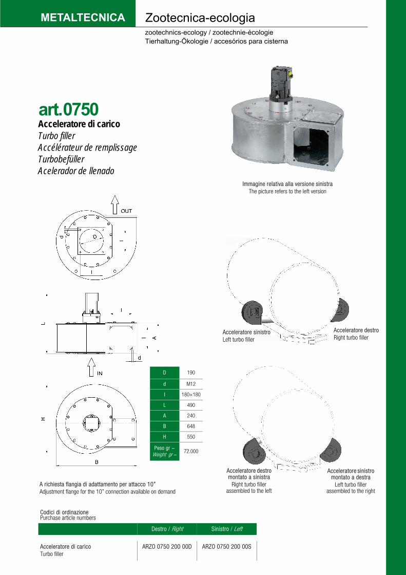
Acceleratore di carico Turbo filler Accélérateur de remplissage Turbobefüller Acelerador de llenado
Zootecnica-ecologia
art.0750
METALTECNICA zootechnics-ecology / zootechnie-écologie Tierhaltung-Ökologie / accesórios para cisterna
Codici di ordinazione Purchase article numbers
Destro / Right Sinistro / Left
Acceleratore di carico Turbo filler
ARZO 0750 200 00D ARZO 0750 200 00S
A richiesta flangia di adattamento per attacco 10” Adjustment flange for the 10” connection available on demand
D 190
d M12
I 180×180
L 490
A 240
B 648
H 550
Peso gr ~ Weight gr ~
72.000
Immagine relativa alla versione sinistraThe picture refers to the left version
Acceleratore sinistroLeft turbo filler
Acceleratore destroRight turbo filler
Acceleratore destromontato a sinistra
Right turbo fillerassembled to the left
Acceleratore sinistromontato a destra
Left turbo filler assembled to the right
L’acceleratore è la soluzione ideale per chi vuole ottimizzare i tempi di riempimento delle botti per liquami. La cisterna viene riempita in maniera veloce ed omogenea, così facendo il liquido risulterà essere più leggero e dosabile con maggiore precisione. L’acceleratore è compatibile con qualsiasi tipo di botte e cisterna. Per garantire un perfetto isolamento tra motore e liquidi trattati, vengono inseriti componenti a tenuta che conferiscono al prodotto la massima resa ed affidabilità nel corso del tempo.
Struttura: acciaio elettrosaldato mat.rif. S235 JR EN 10027/1 Metallo di apporto: UNI EN 14341 G42 M G3 SI 1 SIDERGAS S6 Miscela gas: Argon 87% + CO213% EN 14175 M20 Trattamento protettivo: zincatura a caldo normativa UNI EN ISO 1461, ideale per l’elevatissima resistenza alla corrosione - spessori 150/200 micron Litri max: 4753 Litri medi: 3885 Peso: 72 Kg Requisiti necessari per motore idraulico: minimo 50 l/min a 160 bar massimo 70 l/min a 170 bar montare valvola antiurto
Installazione Montare l’acceleratore nell’impianto in modo che sia in posizione facilmente accessibile e protetta. Per far funzionare l’acceleratore è necessario montare un motore idraulico sull’albero di trasmissione e fissarlo tramite viti al supporto in acciaio situato nella parte frontale dell’acceleratore. Rodaggio Non è previsto un periodo di rodaggio ed è pertanto possibile utilizzare l’acceleratore subito in condizioni di lavoro normali Lubrificazione L’acceleratore deve essere ingrassato nell’apposito ingrassatore ogni 50 ore di funzionamento e prima di fermi di funzionamento prolungati. Sostituire periodicamente gli anelli di tenuta interni al supporto in acciaio e al motore. In caso di perdita di liquido dal foro del supporto in acciaio, fermare immediatamente l’impianto. Eseguire gli interventi di manutenzione a motore spento e tubi idraulici scollegati.
The turbo filler is the ideal solution for those wishing to optimise slurry tanker filler times. Cisterns are filled quicker and in a more homogenous manner, conse-quently resulting in lighter liquid that can be dosed with greater precision. The turbo filler is compatible with almost every type of tank and cistern. To ensure that the liquid treated is fully isolated from the motor, seals are added, guaranteeing maximum yield and reliability of the product over time.
Structure: electro welded steel material reference S235 JR EN 10027/1 Filler metal: UNI EN 14341 G42 M G3 SI 1 SIDERGAS S6 Gas mixture: Argon 87% + CO213% EN 14175 M20 Protective treatment: hot-dip galvanizing, UNI EN ISO 1461, ideal for very high corrosion resistance - 150/200 microns thickness Max. litres: 4753 Average litres: 3885 Weight: 72 kg Necessary requirements for hydraulic motors: minimum 50 l/min at 160 bar, maximum 70 l/min at 170 bar fit anti-shock valves
Installation Fit the turbo filler in the system in an easily accessible and protected position. In order for the turbo filler to work, a hydraulic motor must be fitted on the drive shaft. The motor is to be secured with screws to the steel support on the front of the turbo filler. Run-in The turbo filler does not need to be run in and can be used immediately under normal working conditions Lubrication The turbo filler must be greased with the appropriate lubricator every 50 hours of operation and prior to any prolonged periods of non-use. Periodically replace the sealing rings inside the steel support and on the motor. If liquid leaks from the hole on the steel support, immediately stop the system. Perform any maintenance work with the motor off and the hydraulic hoses uncoupled.
Der Turbobefüller ist die ideale Lösung zur Optimierung der Befüllungszeiten von Güllefässern. Das Fass wird schnell mit einer homogenen Masse befüllt. Die Gülle ist so leichter und exakter dosierbar. Der Turbobefüller ist mit allen Fasstypologien kompatibel. Für eine perfekte Isolierung zwischen Motor und Pumpmedium kommen Dichtungselemente zum Einsatz, die dem Turbobefüller ein Höchstmaß an Förderleis-tung und Betriebszuverlässigkeit gewährleisten.
Gehäuse: Stahl, elektrogeschweißt, Material S235 JR EN 10027/1 Schweißzusatz: UNI EN 14341 G42 M G3 SI 1 SIDERGAS S6 Schutzgas: Argon 87% + CO2 13% EN 14175 M20 Schutzbehandlung: Feuerverzinkung UNI EN ISO 1461 für hohe Korrosionsbeständigkeit - Schichtdicke 150/200 µm Max. Förderleistung: 4.753 l Mittl. Förderleistung: 3.885 l Gewicht: 72 kg Voraussetzungen für Hydraulikmotor: min. 50 l/min bei 160 bar max. 70 l/min bei 170 bar Installation eines Stoßventils erforderlich
Installation Turbobefüller an der Anlage in einer leicht zugänglichen und geschützten Einbauposition installieren. Für den Betrieb des Turbobefüllers ist an der Antriebswelle ein Hydrau-likmotor zu montieren und mittels Schrauben an der Halterung im Frontbereich des Turbobefüllers zu befestigen. Einlaufzeit Es ist keine Einlaufzeit vorgesehen. Der Turbobefüller ist daher sofort unter normalen Betriebsbedingungen einsetzbar. Schmierung Der Turbobefüller muss alle 50 Betriebsstunden und vor längeren Stillstandszeiten mit der hierfür vorgesehenen Fettbüchse gefettet werden. Die internen Dichtungsringe der Stahlhalterung und des Motors sind regelmäßig zu ersetzen. Bei Austritt von Flüssigkeit am Bohrloch der Stahlhalterung ist die Anlage unverzüglich anzuhalten. Wartungsarbeiten sind bei ausgeschaltetem Motor und abgetrennten Hydraulikleitungen auszuführen.