Dimensions in mm This data sheet is designed as a guide and should not be regarded as wholly accurate in every detail. We reserve the right to amend the specification of any product without notice. Page 1 ART241 Differential Pressure Control Valve (DPCV) Differential Pressure Control Valve (DPCV) Technical Data and Installation Instructions PATENTED V2
Transcript
Dimensions in mmThis data sheet is designed as a guide and should not be regarded as wholly accurate in every detail. We reserve the right to amend the specification of any product without notice.
Page 1
ART241 Differential Pressure Control Valve (DPCV)
Differential Pressure Control Valve (DPCV)
Technical Data andInstallation Instructions
PATENTED
V2
Dimensions in mmThis data sheet is designed as a guide and should not be regarded as wholly accurate in every detail. We reserve the right to amend the specification of any product without notice.
Page 2
ART241 Differential Pressure Control Valve (DPCV)
In conformity with directive 97/23/CE PED
Construction and testing norms (correspondences):
Face-to-face: EN 558-1Flanges: EN 1092,Design: EN13445Marking: EN19Testing: 100% testing according to EN 12266
The modulating valves ART 241 balance and control the differential pressure (DPCV) automatically and proportionally.
controls and keeps the differential pressure over the load at a stable value, reducing the risk of noisiness and wear of the thermostatic control valves. Moreover, correcting the imbalances of the supply between the user units assures a better envi-ronmental comfort together with an optimization of the energy consumption. The regulation range of the differential pressure delivered is comprised between 0.2 - 0.8 and 0.8 - 1.6 bar for DN65-100 and between 0.2 and 0.8 bar for DN125-150.The valves perform shut-off and measuring functions.
Advantages: reduces purchasing costs, and installation and set-up times.No need for an external energy supply.
Accessories
5
2
1
7
6
3
4
Electronic instrument for measuring the
of the circuitPressure gauge probe adaptor
capillary pipe, test plug.
1. Internal and external epoxy coating, high temperature resistance, environmentally-friendly water-based paint.
2. Self-sealing test points for quick connection pressure or temperature probes.
3. The large diameter membrane allows accurate measuring of the pressure
4. Differential pressure regulation screws. The associated position indicator allows easy setting of the differential pressure
5. Position indicator may be adjusted to 4 positions for easy reading.
6. The shutter with EPDM seal produces a perfect seal, when maintenance work is done on the system.
7. Safety pressure relief by-pass: limits the allowable differential pressure value across the membrane and prevents the risk of damages and breakage.
Dimensions in mmThis data sheet is designed as a guide and should not be regarded as wholly accurate in every detail. We reserve the right to amend the specification of any product without notice.
Page 3
ART241 Differential Pressure Control Valve (DPCV)
H
F
B
H1
A
V
Cat2011_EKOFLUX.M_p3.drw1_sezdim+matrev. a 6.2.15
n° x D
C
Dimensions (mm)
Weight (kg)
DN 65 80 100 125 150A EN 558-1/1 290 310 350 400 480H 305 316 326 367 381H1 310 400 414 436 460B 200 242 242 242 242V 200 200 200 200 200C 185 200 220 250 285F EN1092 PN16 145 160 180 210 240n x D 4 x 18 8 x 18 8 x 18 8 x 18 8 x 22
Dimensions in mmThis data sheet is designed as a guide and should not be regarded as wholly accurate in every detail. We reserve the right to amend the specification of any product without notice.
Page 4
ART241 Differential Pressure Control Valve (DPCV)
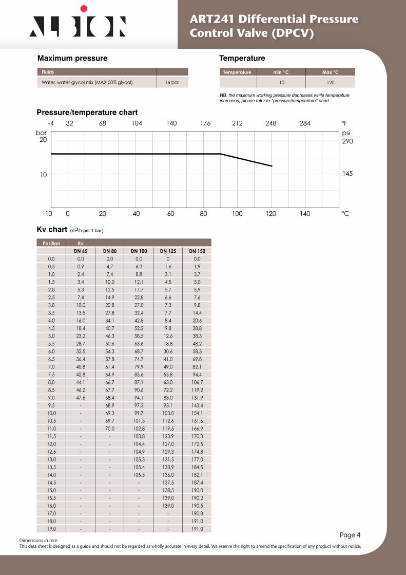
Temperature min ° C Max °C
-10 120
Pressure/temperature chart
Temperature
NB: the maximum working pressure decreases while temperature increases, please refer to “pressure/temperature” chart
Dimensions in mmThis data sheet is designed as a guide and should not be regarded as wholly accurate in every detail. We reserve the right to amend the specification of any product without notice.
Page 5
ART241 Differential Pressure Control Valve (DPCV)
Working range
Refer also to “Instructions and Recommendations”: Regulation of the differential pressure
ATTENTION:Minimum flow rate: indicated in italicsMaximum flow rate: indicated in italics, bold type
ΔP (mbar)
Flow rate l/s
Dimensions in mmThis data sheet is designed as a guide and should not be regarded as wholly accurate in every detail. We reserve the right to amend the specification of any product without notice.
Page 6
ART241 Differential Pressure Control Valve (DPCV)
A) To regulate the differential pressure, turn the command screw (X): turn clockwise to increase the differential pressure, and to stabilize it up to the required value, as indicated in the working range chart. Refer to the digital position indicator as shown in the table below to set the required differential pressure value.B) WARNING: for valves DN125 and DN150, to assure the correct operation, the regulation needle (N) shall be adjusted to match the value set for the positionindicator of the command screw (X).- Loosen the socket head screw (1)- By acting on the screw (2) turn the indicator (3), until the required value is read in correspondence of notch (4)- Tighten socket head screw (1) to lock the position.Note: the position indicator/differential pressure table is given to ease the set-up and cannot substitute a direct pressure measurement.
IMPORTANT: If the differential pressure acting on the membrane is too high, it can lead to damage the membrane itself or other components and thus compromising the valve functionality.ART 241 is equipped with a safety pressure relief by-pass (BP, see the picture above) that limits the allowable differential pressure value across the membrane and prevents the risk of damages and breakage,We recommend anyway to check the correctness of capillary pipes connection as well as the correctness of plant set-up (e.g. the correct position open/close of isolation valves) before plant start-up.
Dimensions in mmThis data sheet is designed as a guide and should not be regarded as wholly accurate in every detail. We reserve the right to amend the specification of any product without notice.
Page 7
ART241 Differential Pressure Control Valve (DPCV)
Instrument for measurementElectronic instrument for the measurement of the differential pressure,
balancing of the circuit.
Project data to be supplied while ordering
• Differential pressure of the user unit ΔPAttention: In order to grant that valve works properly, it is important to assure that the differential pressure ΔH user unit connection to the riser (upstream of the valve) has at least the double value of the differential pressure ΔP across the user unit (ΔH > 2,5 x ΔP)
Accessories
1/4M-1/8F adap-ter, compression
capillary pipe diam. 4mm 2m length, 1/4M test plug.
Complete kit
Fittings, adapter and test plug kit1/4M test plug.
Test plug
4mm 2m length.
Fitting and capillary kit
Pressure gauge probe adaptor. 1/4” F brass body and stainless steel probe.
Adaptor
Versions
ART 241 LP
Body: EN GJL 250Seal: EPDMTemp: -10 +120°CControllable differential pressure range: 0,2 – 0,8 bar
ART 241 HP (DN 65÷100) Body: EN GJL 250Seal: EPDMTemp: -10 +120°CControllable differential pressure range: 0,8 – 1,6 bar
Modulating differential pressure control valve
Coating: RAL 5002 colour
Dimensions in mmThis data sheet is designed as a guide and should not be regarded as wholly accurate in every detail. We reserve the right to amend the specification of any product without notice.
Page 8
ART241 Differential Pressure Control Valve (DPCV)
The information provided here is delivered with each product, and contains “Instructions for use and maintenance”.
RECOMMENDATIONS
caustic liquids. Temperatures above 50°C and below 0°C might cause damage to people.Commissioning, decommissioning and maintenance interventions must be carried out by trained staff, taking account of instructions and local safety regulations.
ADVICE FOR PLANT LAYOUT-and pressure switches.- Observe the following minimum distances between the valve and other system components.
- - In order to ensure that valve works properly, it is important to ensure that the differential pressure ΔH user unit connection to the riser (upstream of the valve) has at least twice value of the differential pressure ΔP across the user unit The differential pressure ΔH should not exceed 4 bar, if cavitation is to be avoided.INSTALLATION AND CONNECTIONS (FIG. 1-2).installation and connections with DPCV mounted in the return pipework (Fig 1) - connect to the flow pipe by means of a capillary tube (supplied separately) between positions M & C1.
installation and connections -connect to the return pipe by means of a capillary tube (supplied separately) between positions M & C2.
NOTE: in case of normal operation the handle must be completely open.
ABOUT CAVITATION
corresponding static pressure decreases. If the static pressure value drops below the vapour pressure level, steam bubbles will form. These bubbles will be carried
high temperatures and pressure shock waves locally, which will damage the valve and cause vibrations and noise. Higher temperatures, lower static pressure and higher pressure drops across the valve usually increase the risk of cavitation.
Instructions and Recommendations
2DN 5DN 2DN 10DN
DISTANCE FROM UPSTREAM DOWNSTREAMPump 10 x DN -Bends, T-joints 5 x DN 2 x DN
FIG.1 FIG.3
C2
B
C1
∆H
∆P
M
C2
C1
B
M
∆H
∆P
M
C2
B
C1
FIG.2
with DPCV mounted in the flow pipework (Fig 2)
Fig 1 Return mounted DPCV C2 to Test plug B shown in red (already installed)
Fig 2 Flow mounted DPCV C1 to B shown in red (already installed)
Dimensions in mmThis data sheet is designed as a guide and should not be regarded as wholly accurate in every detail. We reserve the right to amend the specification of any product without notice.
Page 9
ART241 Differential Pressure Control Valve (DPCV)
STORING- Keep the valve in a dry place, protect from damage and dirt.- Handle with care, avoid knocks, especially on the weaker parts (hand wheel).- Do not lift the valve by the hand wheel.- Use suitable, sturdy packing for transport.
INSTALLATION- Do not lift the valve by the hand wheel.- Before installation, check that: • The piping is clean • The valve is clean and undamaged
- Use suitable gaskets and check that they are correctly centred.ve.
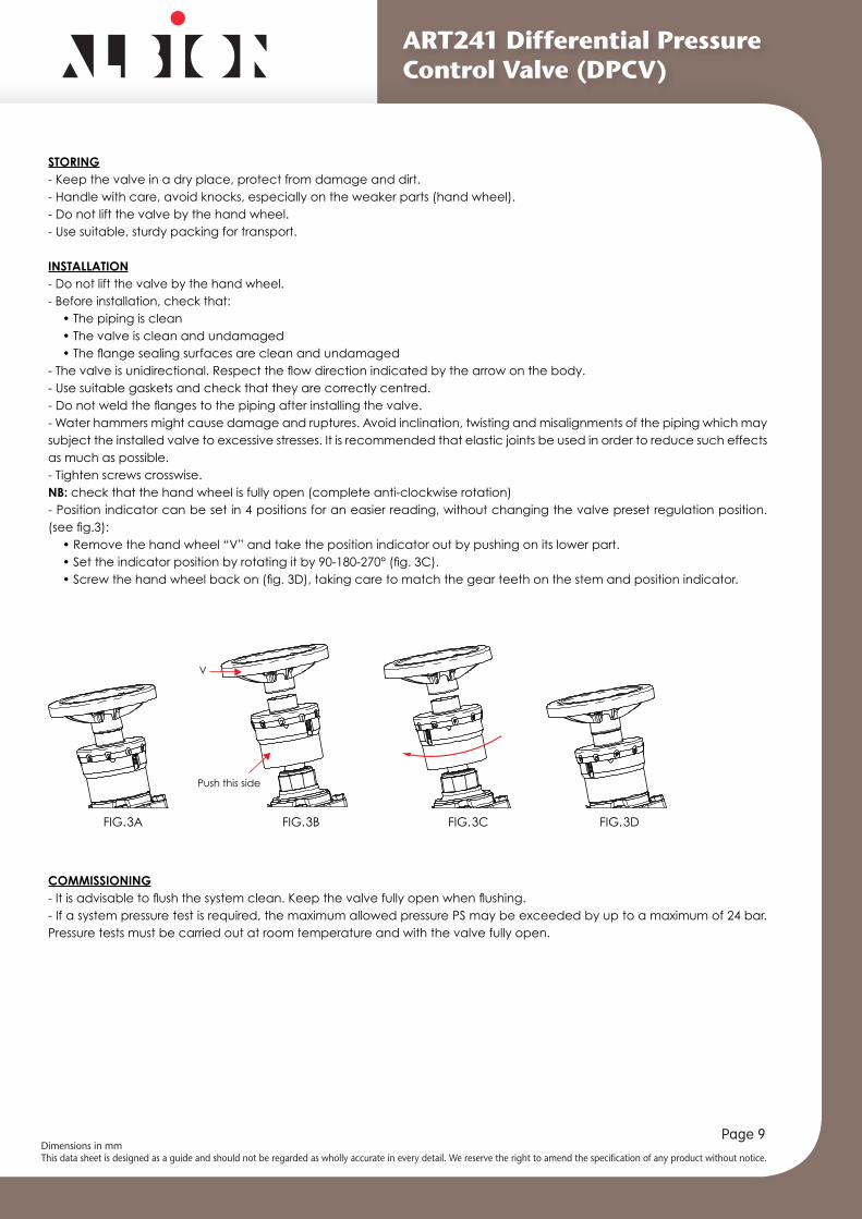
- Water hammers might cause damage and ruptures. Avoid inclination, twisting and misalignments of the piping which may subject the installed valve to excessive stresses. It is recommended that elastic joints be used in order to reduce such effects as much as possible.- Tighten screws crosswise. NB: check that the hand wheel is fully open (complete anti-clockwise rotation)- Position indicator can be set in 4 positions for an easier reading, without changing the valve preset regulation position.
• Remove the hand wheel “V” and take the position indicator out by pushing on its lower part.
COMMISSIONING
- If a system pressure test is required, the maximum allowed pressure PS may be exceeded by up to a maximum of 24 bar. Pressure tests must be carried out at room temperature and with the valve fully open.
V
FIG.3A FIG.3B FIG.3C FIG.3D
Push this side
Dimensions in mmThis data sheet is designed as a guide and should not be regarded as wholly accurate in every detail. We reserve the right to amend the specification of any product without notice.
Page 10
ART241 Differential Pressure Control Valve (DPCV)
MEASURINGPay close attention during measurement, in the case of hot media.
- We recommend placing an isolation valve upstream of the probe. - After measuring, unscrew and extract the probe. Screw the plug cap back on.
• Open the valve fully (complete anti-clockwise rotation).• Screw the pressure gauge connection to the pressure plugs.• Turn the hand wheel clockwise observing the pressure gauge connection. The gauge indicator is stable as long as the
• Stop turning as soon as the gauge indicator moves (differential pressure increasing).• Take note of differential pressure reading on pressure gauge.
• When the measurements have been done, put the valve in the fully open position (complete anti-clockwise rotation of the hand wheel).
REGULATION OF THE DIFFERENTIAL PRESSURE- Open the valve fully (complete anti-clockwise rotation).-
- Tighten until it stops turning, and replace the cover “P”.- To regulate the differential pressure, turn the command screw “X”: turn clockwise to increase the differential pressure, up to
ΔP (bar) Differential pressure reading on the pressure gauge Kv correspondence with the number of turns made, read on the hand wheel position indicator Q (m3/h)
ΔPQ=Kv · √⎯
FIG.5
S
P
XIstruzioni EkofluxS + M montaggio prese pressione
FIG.4A FIG.4B
Dimensions in mmThis data sheet is designed as a guide and should not be regarded as wholly accurate in every detail. We reserve the right to amend the specification of any product without notice.
Page 11
ART241 Differential Pressure Control Valve (DPCV)
SETTINGHand wheel mounting can be set for an easier reading, see chapter entitled “Installation”.The regulation position can be read from the digital setting scales, showing basic settings (number of complete turns) and
Position 0.0 coincides with the valve being fully closed.
SCHEMEIn an heating/conditioning plant, because of the distance of the pump and of the plant layout, some user units are subjected to a differential pressure higher than
represent pressure upstream and downstream the user units, and the rods’ red part represent the differential pressure, which varies widely among the circuits (ΔP1-2 > ΔP3-4 > ΔP5-6 > ΔP7-8 > ΔP9-0).
-tively comfort (requested temperature are reached after a long time, or not reached at all, resulting in unstable temperature), control as well the energy consumption raise and wear of user unit control valve.
Placing a balancing valve ART 241 upstream of the user unit,
provides hydronic balanc and allows to keep the optimum differential pressure on the user unit control valve (in red, ΔP1-2 = ΔP3-4 = ΔP5-6 = ΔP7-8 = ΔP9-0).A differential pressure control valve gives the further advantage to keep constant the differential pressure
in the plant (e.g. end user circuit opening/closing, temperature variations).