Analytical and numerical investigation of the radiation from concentric metamaterial spheres excited by an electric Hertzian dipole Samel Arslanagic, 1 Richard W. Ziolkowski, 2 and Olav Breinbjerg 1 Received 19 March 2007; revised 20 July 2007; accepted 6 August 2007; published 19 October 2007. [1] The canonical problem of an electric Hertzian dipole radiating in the presence of a pair of concentric double negative metamaterial spheres is investigated analytically and numerically. The spatial distribution of the near field as well as the total radiated power are examined. The results are compared to those for the corresponding structures made of conventional double positive materials. It is shown that electrically small concentric metamaterial spheres can be designed to be resonant and that these resonant designs lead to significant changes in the field radiated by the electric Hertzian dipole and, in particular, to significant enhancements of the total power radiated by it. The impact of the location of the electric Hertzian dipole in both radiating and scattering configurations is studied in detail. Furthermore, the influence of dispersion and loss is investigated. Finally, a few results for larger size metamaterial concentric spheres are given. Citation: Arslanagic, S., R. W. Ziolkowski, and O. Breinbjerg (2007), Analytical and numerical investigation of the radiation from concentric metamaterial spheres excited by an electric Hertzian dipole, Radio Sci., 42, RS6S16, doi:10.1029/2007RS003663. 1. Introduction [2] Recent years have witnessed an increased interest in various classes of metamaterials (MTMs), such as double-negative (DNG) and single-negative (SNG) materials, as well as combinations of these with conventional double-positive (DPS) materials. A sig- nificant amount of work has already been performed on fundamental issues as well as potential applications [see, e.g., Caloz and Itoh, 2006; Eleftheriades and Balmain, 2005; Engheta and Ziolkowski, 2006, and references therein]. [3] The increased interest in MTMs is mainly due to the unusual properties of DNG materials [Veselago, 1968] which are characterized by a negative real part of the permittivity as well as the permeability. These unusual properties are not present in conventional DPS materials which are characterized by a positive real part of those parameters. In particular, the concept of the so- called perfect lens [Pendry , 2000], consisting of a spe- cific DNG slab, has attracted much attention. Moreover, combinations of DNG and DPS materials have lead to a new paradigm in the miniaturization of devices such as cavity resonators [Engheta, 2002], waveguides [Alu ´ and Engheta, 2004], scatterers [Alu ´ and Engheta, 2005; Arslanagic et al., 2006], and antennas [Alu ´ et al., 2007; Arslanagic et al., 2006; Stuart and Pidwerbetsky , 2006; Ziolkowski and Erentok, 2006; Ziolkowski and Kipple, 2003, 2005]. Many of these ideas were based on the observed properties of such electrically small MTM-based structures when illuminated by plane waves or by localized sources such as an electric Hertzian dipole (EHD) or an electric line source (ELS). In particular, it has been observed that such electrically small MTM-based structures can be designed to be resonant and that these resonant designs lead to signif- icant enhancements of the total radiated power or the total scattering cross section. This is in contrast to electrically small structures made of only conventional DPS materials. [4] The purpose of this work is to further investigate the radiation properties of electrically small spherical MTM-based structures that are excited by an arbitrarily oriented and located EHD. In extension of the works of Ziolkowski and Kipple [2003, 2005], where the EHD is located at the origin, the present work inves- tigates also other EHD locations and documents the RADIO SCIENCE, VOL. 42, RS6S16, doi:10.1029/2007RS003663, 2007 Click Here for Full Articl e 1 ØrstedDTU, ElectroScience Section, Technical University of Denmark, Lyngby, Denmark. 2 Department of Electrical and Computer Engineering, University of Arizona, Tucson, Arizona, USA. Copyright 2007 by the American Geophysical Union. 0048-6604/07/2007RS003663$11.00 RS6S16 1 of 20
Transcript
Analytical and numerical investigation of the radiation from
concentric metamaterial spheres excited by an electric Hertzian
dipole
Samel Arslanagic,1 Richard W. Ziolkowski,2 and Olav Breinbjerg1
Received 19 March 2007; revised 20 July 2007; accepted 6 August 2007; published 19 October 2007.
[1] The canonical problem of an electric Hertzian dipole radiating in the presence of apair of concentric double negative metamaterial spheres is investigated analytically andnumerically. The spatial distribution of the near field as well as the total radiated power areexamined. The results are compared to those for the corresponding structures made ofconventional double positive materials. It is shown that electrically small concentricmetamaterial spheres can be designed to be resonant and that these resonant designs leadto significant changes in the field radiated by the electric Hertzian dipoleand, in particular, to significant enhancements of the total power radiated by it. The impactof the location of the electric Hertzian dipole in both radiating and scattering configurationsis studied in detail. Furthermore, the influence of dispersion and loss is investigated.Finally, a few results for larger size metamaterial concentric spheres are given.
Citation: Arslanagic, S., R. W. Ziolkowski, and O. Breinbjerg (2007), Analytical and numerical investigation of the radiation
from concentric metamaterial spheres excited by an electric Hertzian dipole, Radio Sci., 42, RS6S16,
doi:10.1029/2007RS003663.
1. Introduction
[2] Recent years have witnessed an increased interestin various classes of metamaterials (MTMs), such asdouble-negative (DNG) and single-negative (SNG)materials, as well as combinations of these withconventional double-positive (DPS) materials. A sig-nificant amount of work has already been performedon fundamental issues as well as potential applications[see, e.g., Caloz and Itoh, 2006; Eleftheriades andBalmain, 2005; Engheta and Ziolkowski, 2006, andreferences therein].[3] The increased interest in MTMs is mainly due to
the unusual properties of DNG materials [Veselago,1968] which are characterized by a negative real partof the permittivity as well as the permeability. Theseunusual properties are not present in conventional DPSmaterials which are characterized by a positive real partof those parameters. In particular, the concept of the so-called perfect lens [Pendry, 2000], consisting of a spe-
cific DNG slab, has attracted much attention. Moreover,combinations of DNG and DPS materials have lead to anew paradigm in the miniaturization of devices such ascavity resonators [Engheta, 2002], waveguides [Alu andEngheta, 2004], scatterers [Alu and Engheta, 2005;Arslanagic et al., 2006], and antennas [Alu et al.,2007; Arslanagic et al., 2006; Stuart and Pidwerbetsky,2006; Ziolkowski and Erentok, 2006; Ziolkowski andKipple, 2003, 2005]. Many of these ideas were basedon the observed properties of such electrically smallMTM-based structures when illuminated by plane wavesor by localized sources such as an electric Hertziandipole (EHD) or an electric line source (ELS). Inparticular, it has been observed that such electricallysmall MTM-based structures can be designed to beresonant and that these resonant designs lead to signif-icant enhancements of the total radiated power or thetotal scattering cross section. This is in contrast toelectrically small structures made of only conventionalDPS materials.[4] The purpose of this work is to further investigate
the radiation properties of electrically small sphericalMTM-based structures that are excited by an arbitrarilyoriented and located EHD. In extension of the worksof Ziolkowski and Kipple [2003, 2005], where theEHD is located at the origin, the present work inves-tigates also other EHD locations and documents the
RADIO SCIENCE, VOL. 42, RS6S16, doi:10.1029/2007RS003663, 2007ClickHere
for
FullArticle
1Ørsted�DTU, ElectroScience Section, Technical University ofDenmark, Lyngby, Denmark.
2Department of Electrical and Computer Engineering, University ofArizona, Tucson, Arizona, USA.
Copyright 2007 by the American Geophysical Union.
0048-6604/07/2007RS003663$11.00
RS6S16 1 of 20
properties and advantages of such configurations. Inparticular, it is shown that these structures remain reso-nant independent of the source location or orientation andthat they still lead to significant enhancements of the totalradiated power as compared to the power radiated by theEHD in free space. It is emphasized that the presentinvestigation is entirely theoretical as it assumes theexistence of electrically small DNG materials and consid-ers a canonical configuration with an impressed Hertziandipole source.[5] The present manuscript is organized as follows. In
section 2, the analytical solution is derived for theproblem of an arbitrarily located and oriented EHDradiating in the presence of a pair of concentric MTMspheres. This section also defines quantities which areused in subsequent numerical investigations of thesestructures. The condition for resonance in the electri-cally small designs is derived and discussed in section3, while section 4 presents a detailed numerical inves-tigation of the near-field spatial distribution and thetotal radiated power of these designs. Two types ofstructures, referred to as the dipolar and quadrupolarones, are studied in section 4. The influence of disper-sion and loss, present in any realistic MTM, is takeninto account in section 5, while the properties ofstructures having larger electrical sizes are discussedin section 6. The potential use of SNG materials insimilar electrically small designs is clarified in section 7.The entire work is summarized and concluded in
section 8. Throughout this manuscript, the time factorexp(jwt) with w being the angular frequency, and tbeing the time, is assumed and suppressed.
2. Analytical Solution
2.1. Configuration
[6] The configuration of interest is depicted inFigure 1. A sphere (region 1) of radius r1 is coveredwith a concentric spherical shell of radius r2 (region 2) andimmersed in an infinite ambient medium (region 3). Theconcentric MTM spheres are illuminated by an EHDpossessing the dipole moment ~ps = ps ps with theorientation ps and complex magnitude ps [Am]. TheEHD can be located in any of the three regions andcan possess an arbitrary orientation and complex mag-nitude of the dipole moment. The EHD constitutes amodel of an electrically short dipole with ps being theproduct of the current and length of that dipole. Region i,with i = 1 and 2, is characterized by a permittivity and apermeability, denoted by ei = ei
0 ÿ jei00 and mi = mi
0 ÿjmi
00, respectively, while the wave number inside region iis ki = w
ffiffiffiffiffiffiffiffi
eimi
p, where the branch of the square root is
chosen such that Im{ki } � 0. Both region 1 and 2 can becomposed of simple DPS, DNG, and/or SNG materials.The exterior region, region 3, is free space with thepermittivity e0 and permeability m0. Thus, its wave num-ber is k0 = w
ffiffiffiffiffiffiffiffiffi
e0m0p
and intrinsic impedance h0 =ffiffiffiffiffiffiffiffiffiffiffiffi
m0=e0p
.A spherical coordinate system (r, q, f ) and the associatedCartesian coordinate system (x, y, z) are introduced suchthat the origin coincides with the common center of thespheres. The coordinates of the observation point and theEHD are (r, q, f ) and (rs, qs, fs ), respectively.
2.2. Field of the EHD
[7] Following the approach of Jones [1965, chapter 8],the electric field generated by the EHD in an infinitemedium, characterized by eEHD, mEHD, and kEHD, can beexpressed as an expansion of spherical transverse mag-netic (TM) and transverse electric (TE) waves
~EEHD r; q;fð Þ
~HEHD r; q;fð Þ
8
<
:
9
=
;
¼X
Nmax
n¼1
X
n
m¼ÿn
1
jweEHDmEHD
a cð Þnm~N TMð Þ; cð Þnm
b cð Þnm~N TEð Þ; cð Þnm
8
<
:
9
=
;
2
4
þÿ1=eEHDð Þb cð Þ
nm~M TEð Þ; cð Þ
nm
1=mEHDð Þa cð Þnm
~M TMð Þ; cð Þnm
8
<
:
9
=
;
3
5;
ð1Þ
Figure 1. Configuration of the EHD-excited concentricpair of MTM spheres.
RS6S16 ARSLANAGIC ET AL.: INVESTIGATION OF METAMATERIAL SPHERES
2 of 20
RS6S16
where the familiar spherical vector wave functions(SVWFs) are
~M Gð Þ; cð Þnm r; q;fð Þ ¼ gEHDw
cð Þn kEHDrð Þe jmf
� jm
sin qPjmjn cos qð Þqÿ d
dqPjmjn cos qð Þf
� �
;
ð2Þ
~N Gð Þ; cð Þnm r; q;fð Þ ¼ gEHD
n nþ 1ð Þr
w cð Þn kEHDrð ÞPjmj
n cos qð Þ
� e jmfr þ gEHD1
r
d
drfrw cð Þ
n kEHDrð Þg
� ddq
Pjmjn cos qð Þejmfqþ gEHD
1
r
d
dr
� frw cð Þn kEHDrð Þg jm
sin qPjmjn cos qð Þe jmff;
ð3Þ
with gEHD = eEHD for G = TE, and gEHD = mEHD for G =TM, and with wn
(c) (�) being a specific spherical functionto be introduced below. The quantities anm
(c) and bnm(c) are
the TM and TE expansion coefficients, respectively, ofthe EHD field which can be expressed as
a cð Þnm ¼ ÿ jkEHD
ps
4p
1
mEHD
2nþ 1
n nþ 1ð Þnÿ jmjð Þ!nþ jmjð Þ!
� ps � ~NTMð Þ; 5ÿcð Þn;ÿm rs; qs;fsð Þ
n o
; ð4Þ
and
b cð Þnm ¼ k3EHD
w
ps
4p
1
e2EHD
2nþ 1
n nþ 1ð Þnÿ jmjð Þ!nþ jmjð Þ!
� ps � ~MTEð Þ; 5ÿcð Þn;ÿm rs; qs;fsð Þ
n o
: ð5Þ
[8] For r < rs c is equal to 1, and for r > rs c is equal to4. The function wn
(1)(�) = jn(�), where jn(�) is the sphericalBessel function of order n, is chosen to represent the fieldfor r < rs due to its nonsingular behavior at the origin,while wn
(4)(�) = hn(2)(�), hn(2)(�) being the spherical Hankel
function of second kind and order n, is chosen for r > rsbecause it represents an outward propagating wavecomplying with the radiation condition. The functionPnjmj is the associated Legendre function of the first kind
of degree n and order jmj. The symbol Nmax is thetruncation limit in a practical numerical implementationof the infinite summation in the exact solution and ischosen in a manner that ensures the convergence of thisexpansion. When the EHD is located in regions 1 and 2,eEHD = ei, mEHD = mi, and kEHD = ki, for i = 1 and 2,
respectively, while eEHD = e0, mEHD = m0, and kEHD = k0when the EHD is in region 3.
2.3. Unknown Fields
[9] The unknown fields in each of the three regions,i.e., the scattered field in the region containing the EHDand the total fields in the other regions, are likewiseexpanded in terms of SVWFs. Therefore, these can beexpressed as
~E1s r; q;fð Þ~H1s r; q;fð Þ
( )
¼X
Nmax
n¼1
X
n
m¼ÿn
1
jwe1m1
A1;nm~N
TMð Þ; 1ð Þnm
B1;nm~N
TEð Þ; 1ð Þnm
8
<
:
9
=
;
2
4
þ ÿ1=e1ð ÞB1;nm~M TEð Þ; 1ð Þ
nm
1=m1ð ÞA1;nm~M TMð Þ; 1ð Þ
nm
( )#
for r � r1; ð6aÞ
~E2s r; q;fð Þ~H2s r; q;fð Þ
( )
¼
X
Nmax
n¼1
X
n
m¼ÿn
1
jwe2m2
A2;nm~N TMð Þ; 1ð Þnm þ A3;nm
~N TMð Þ; 2ð Þnm
B2;nm~N TEð Þ; 1ð Þnm þ B3;nm
~N TEð Þ; 2ð Þnm
( )"
þÿ1=e2ð Þ B2;nm
~M TEð Þ; 1ð Þnm þ B3;nm
~M TEð Þ; 2ð Þnm
ÿ �
1=m2ð Þ A2;nm~N TMð Þ; 1ð Þnm þ A3;nm
~N TMð Þ; 2ð Þnm
ÿ �
( )#
for r1 � r � r2;
~E3s r; q;fð Þ~H3s r; q;fð Þ
( )
¼X
Nmax
n¼1
X
n
m¼ÿn
1
jwe0m0
A4;nm~N
TMð Þ; 4ð Þnm
B4;nm~N
TEð Þ; 4ð Þnm
8
<
:
9
=
;
2
4
þ ÿ1=e0ð ÞB4;nm~M TEð Þ; 4ð Þ
nm
1=m0ð ÞA4;nm~M TMð Þ; 4ð Þ
nm
( )#
for r � r2; ð6cÞ
where Ai,nm, i = 1,. . ., 4 are the unknown expansioncoefficients associated with the TM part of the fields and,henceforth, are referred to as the TM coefficients, whileBi,nm, i = 1,. . ., 4 are the unknown expansion coefficientsassociated with the TE part of the fields and, henceforth,are referred to as the TE coefficients. It is noted that theexpansion in (6b) also contains the function wn
(2)(�) =yn(�), where yn(�) is the spherical Neumann function oforder n. The expressions (1) and (6a)–(6c) representmultipole expansions of the respective fields, i.e., the n =1 term (for which m = ÿ1, 0, and 1) corresponds to thedipolar mode, the n = 2 term (for which m = ÿ2, ÿ 1, 1,2) corresponds to the quadrupolar mode, and similarlyfor the other terms.
ð6bÞ
RS6S16 ARSLANAGIC ET AL.: INVESTIGATION OF METAMATERIAL SPHERES
3 of 20
RS6S16
[10] Enforcing the electromagnetic field boundary con-ditions, i.e., the continuity of the tangential componentsof the electric and magnetic fields at the interfaces r = r1and r = r2, it can be shown that the unknown expansioncoefficients are found from the following matrix relation
~Dnm ¼ ��Sn
� �ÿ1~Ynm; n ¼ 1; 2; . . .Nmax
and m ¼ ÿn; . . . ; nð7Þ
where ~Dnm = [A1,nm,, . . ., A4,nm, B1,nm,, . . ., B4,nm] is thevector containing the eight unknown expansion coeffi-cients, and ~Y nm = [Y1,nm,, . . ., Y8,nm,] is the excitationvector which depends on the location of the EHD. Theelements of this excitation vector, when the EHD islocated in regions 1, 2 or 3, are shown in Table 1.[11] In Table 1, as well as in certain forthcoming
relations, use is made of the expression
d0r¼rkrkw
cð Þn kirkð Þ
n o
¼ w cð Þn kirkð Þ þ kirkw
cð Þ0n kirkð Þ; ð8Þ
where wn(c)0(x) = dwn
(c) (x)/dx. The matrix ��Sn is an eight-by-eight matrix that depends on the values of the SVWFsat the two interfaces. The explicit form of this matrix isgiven by
��Sn ¼��An
��0��0 ��Bn
� �
; ð9Þ
where ��0 is a four-by-four zero matrix, ��An =��Gn (gi = ei , i =
1, 2 ; g3 = e0) and��Bn =
��Gn (gi = mi , i = 1, 2 ; g3 = m0), with
the matrix ��Gn having the form of
��Gn ¼
jn k1r1ð Þ jn k2r1ð Þ ÿyn k2r1ð Þ 0
d0r¼r1rjn k1rð Þf g ÿ g1
g2d0r¼r1
rjn k2rð Þf g ÿ g1g2
d0r¼r1ryn k2rð Þf g 0
0 jn k2r2ð Þ yn k2r2ð Þ ÿh 2ð Þn k0r2ð Þ
0 d0r¼r2rjn k2rð Þf g d0r¼r2
ryn k2rð Þf g ÿ g2g3
d0r¼r2rh 2ð Þ
n k0rð Þn o
2
6
6
6
6
6
4
3
7
7
7
7
7
5
:
ð10Þ
[12] It is interesting to note that the first four elements ofthe excitation vector~Y nm, i.e., Yi,nmwith i = 1, 2, 3, and 4,see Table 1, are used only in the determination of theunknown TM coefficients Ai,nm, while the last four ele-ments of this vector, i.e., Yi,nm with i = 5, 6, 7, and 8, areused in the determination of the unknown TE coefficientsBi,nm. This matrix structure is due to the fact that the TMand TE spherical modes are linearly independent and,hence, their coefficients are uncoupled. In other words, thelinear system of equations used to determine the unknownTM coefficients, and the one used to determine theunknown TE coefficients, and vice versa, are uncoupled.As a consequence, relation (7) is split into two relations fornumerical convenience, each involving a four-by-fourmatrix of the form given by (10) to determine the Ai,nm
on the one hand, and Bi,nm on the other. This fact will alsobe used in section 3 in order to obtain the conditions forresonance.
2.4. Total Radiated Power
[13] In the numerical studies of several MTM-basedstructures conducted in section 4, a thorough investigationof their spatial near-field distributions will be undertaken.Aside from these near-field investigations, significantattention will also be devoted to the total radiated power,Pt, henceforth termed the total power. The total power isgiven by the expression
Pt ¼ limr!1
1
2
Z
p
q¼0
Z
2p
8¼0
Re ~Et r; q;8ð Þ � ~H�t r; q;fð Þ
�
� d~s;
ð11Þ
Table 1. Elements Yi,nm, i = 1, . . ., 8 of the Excitation Vector ~Ynm When the EHD is Located in
Regions 1, 2, or 3
Yi,nm EHD in Region 1 EHD in Region 2 EHD in Region 3
Y1,nm ÿ anm(4) hn
(2)(k1r1) anm(1) jn (k2r1) 0
Y2,nm ÿ anm(4) dr=r1
0 {rhn(2) (k1r)} (e1/e2)anm
(1)dr=r10 {rjn (k2r)} 0
Y3,nm 0 ÿ anm(4) hn
(2) (k2r2) anm(1) jn (k0r2)
Y4,nm 0 ÿ anm(4) dr=r2
0 {rhn(2)(k2r)} (e2/e0)anm
(1) d 0r=r2 {rjn (k0r)}
Y5,nm ÿ bnm(4) hn
(2)(k1r1) bnm(1) jn (k2r1) 0
Y6,nm ÿ bnm(4) dr=r1
0 {rhn(2) (k1r)} (m1/m 2)bnm
(1) d 0r=r1
{rjn (k2r)} 0Y7,nm 0 ÿ bnm
(4) hn(2) (k2r2) bnm
(1) jn (k0r2)Y8,nm 0 ÿ bnm
(4) d0r=r2 {rhn(2) (k2r)} (m2/m0)anm
(1) d 0r=r2 {rjn (k0r)}
ð10Þ
RS6S16 ARSLANAGIC ET AL.: INVESTIGATION OF METAMATERIAL SPHERES
4 of 20
RS6S16
where * denotes the complex conjugate and d~s = rr2 sinqdfdq is the outward pointing surface differentialelement. In addition, ~Et and ~H t denote the total electricand magnetic field, respectively, in region 3. When theEHD is in region 3, these total fields are equal to the sumof the field generated by the EHD (1) defined for r > rsand the field (6c), while they equal the field (6c) whenthe EHD is located in either region 1 or 2. Theexpression for the total electric and magnetic fields in(11) is easily obtained by introducing the large argumentexpansions of the involved spherical Hankel functions[Abramowitz and Stegun, 1965, chapter 11]. The finalexpression for the total power then takes the form
Pt ¼2p
wk0
X
1
n¼1
X
n
m¼ÿn
n nþ 1ð Þ2nþ 1
nþ jmjð Þ!nÿ jmjð Þ!
� 1
e0janmj2 þ
1
m0jbnmj2
� �
; ð12Þ
where anm = anm(4) + A4,nm, bnm = bnm
(4) + B4,nm if the EHDis located in region 3, and anm = A4,nm, bnm = + B4,nm ifthe EHD is located in either region 1 or 2.[14] The power radiated by the EHD when it is situated
alone in free space is denoted by Pi and is given by (12)with anm = anm
(4) and bnm = bnm(4). However, the power
radiated by the EHD in free space has a considerablysimpler and well-known form if it is not expressed interms of the spherical vector wave functions. In partic-ular, with Balanis [1989, p. 137] one finds
Pi ¼h0p
3
psk0
2p
�
�
�
�
�
�
�
�
2
: ð13Þ
Of particular interest to the present work is thecomparison of the total power radiated in the presenceof the concentric MTM spheres to that radiated by theEHD alone in free space. To this end, the quantitydesignated as the power ratio (PR) is introduced. It isgiven by
PR ¼ Pt
Pi
; ð14Þ
with Pt and Pi given by (12) and (13), respectively. It isnoted that we employ here an impressed Hertzian dipoleas the source which corresponds to a constant currentgenerator.[15] It is noted that the PR in (14) is equivalent to the
radiation resistance of the EHD radiating in the presenceof the structure normalized by the radiation resistance ofthe EHD radiating in free space. However, the inputimpedance cannot be properly defined since the EHD isan idealized source. Thus the PR simply measures therelative performance of two idealized canonical config-urations: the EHD with or without the MTM-based
structure. In the consideration of realistic antennas, theissue of impedance matching the antenna to the source isprofoundly important. We do not address this practicalissue here since it has been considered by Ziolkowskiand Erentok [2006]. Instead, we concentrate on thephysical properties and responses of the canonicalMTM-based systems in both their radiating and scatter-ing configurations.
3. Resonance Condition: Discussion and
Derivation
[16] Prior to presenting the results for specific electri-cally small structures, it is useful to derive the conditionsfor which they become resonant; i.e., they provideenhancements of the total power. Specific details onthe derivation of these conditions have already beenreported by, e.g., Alu and Engheta [2005], Arslanagicet al. [2006], and Ziolkowski and Kipple [2005] forcylindrical and spherical structures; thus, only the mainpoints associated with the spherical structures areincluded below.[17] With the objective of enlarging the total power in
(12) and, hence, the PR in (14), the amplitudes of thecoefficients A4,nm and/or B4,nm must be large. When thespheres are made of DPS materials only, these coeffi-cients become large only when the sizes of the spheresare on the order of, or larger, than the wavelengths in thematerials [Engheta and Ziolkowski, 2006, chapter 2].These resonances are referred to as the wavelength-sizednatural resonances of the structure [Arslanagic et al.,2006]. As the size of the object becomes electricallysmall, these resonances are lost since the natural modescannot exist below a certain cutoff size [Engheta andZiolkowski, 2006, chapter 2]. In contrast to this, thecoefficients may exhibit a resonance when the structureconsists of specific combinations of DPS, DNG, and/orSNG materials, even if the structure is electrically small.This is due to the presence of the so-called subwave-length-sized natural resonances (also termed interfaceresonances by Engheta and Ziolkowski [2006,chapter 2] and Alu and Engheta [2005]) in such electri-cally small structures [see Engheta and Ziolkowski,2006, chapter 2; Alu and Engheta, 2005; Arslanagicet al., 2006; Ziolkowski and Kipple, 2005].[18] In order to find the condition for which the ampli-
tudes of A4,nm and B4,nm become large, it is first recalledthat these coefficients are determined independently ofeach other. The TM coefficients A4,nm are proportional to
the product of the inverse of the matrix ��An and the first fourelements of the excitation vector~Y nm, i.e.,Yi,nmwith i = 1,2, 3, and 4, while the TE coefficients B4,nm are propor-tional to the product of the inverse of the matrix ��Bn and thelast four elements of the excitation vector ~Ynm, Yi,nm with
RS6S16 ARSLANAGIC ET AL.: INVESTIGATION OF METAMATERIAL SPHERES
5 of 20
RS6S16
i = 5, 6, 7, and 8. Then, in similitude with the procedureoutlined in the work of Arslanagic et al. [2006] for thecase of concentric MTM-based cylinders illuminated byan ELS, it is found that A4,nm and B4,nm become largewhen the magnitudes of the determinants of ��An and
��Bn,respectively, attain a minimum. As the structures areelectrically small, the small argument expansions of thefunctions in ��An and ��Bn, which hold when the productsjk1jr1jk2jr1jk2jr2, and k0r2 are much smaller than unity,are used to derive the approximate analytical expressionsfor which the resonances will occur. The derivation ofthese resonance conditions is facilitated significantly byassuming that the materials in regions 1 and 2 arelossless. For the range of parameters to be investigatedhere, it can be shown that the TM coefficients A4,nmexhibit a resonance subject to the approximate condition
[19] The conditions (15a) and (15b) are used to deter-mine, for a given set of material parameters, the approx-imate ratio of r1 and r2 that will produce a resonantdesign. The condition for the electrically small resonantstructure given by (15) depends on the mode number, n,the values of the permittivity and permeability of thethree regions, and, most importantly, on the ratio of theinner and outer radii of region 2. The resonance condi-tion therefore does not depend on the absolute size ofthese radii. A given resonant structure is defined on thebasis of (15), e.g., by first selecting the material param-eters and the mode number n that is to be excited as thedominant mode, and then selecting the inner (outer)radius. Subsequently, (15) gives the outer (inner) radiusof the structure at which the resonance occurs. It is notedthat certain small terms have been neglected in thederivation of (15). Thus, as will be demonstrated below,this condition only constitutes an approximation for theradii ratio at resonance and serves as a guideline toestimate the resonant configuration, i.e., as a startingpoint for the numerical analysis. Since it is implementedwithout the use of any small argument expansions, thenumerical solution will, of course, be exact. The valuesof r1 and r2 so obtained will be the ones used to definethe resonant structures that lead to the performanceenhancements demonstrated below. It must be noted thatrelation (15) has also been derived by Engheta and
Ziolkowski [2006, chapter 2] and Alu and Engheta[2005] for plane wave scattering from similar sphericalstructures. Furthermore, the condition (15a) for the n = 1term has likewise been derived and discussed by Kerkerand Blatchford [1982].[20] As noted in the beginning of this section, large
values of the total power and, hence, the PR may result ifeither A4,nm or B4,nm exhibit a resonance. In this regard,only (15b) or (15b), depending on the specific configu-ration, needs to be satisfied. According to Engheta andZiolkowski [2006, chapter 2], and Alu and Engheta[2005], at least one of the parameters, e1 or e2 for(15a), and m1 or m2 for (15b), must be negative in orderto satisfy the resonance conditions (15a) or (15b). In thework of Kerker and Blatchford [1982] it has also beenpointed out that for (15a) with n = 1 the permittivities ofregions 1 and 2 must have opposite signs to fulfill thecondition. Thus, in this case, an ENG or MNG material,respectively, is needed in at least one of the regions 1 or2. On the other hand, the simultaneous fulfillment of(15a) and (15b) requires either that at least one of theregions, 1 or 2, be a DNG material or that ENG-MNG orMNG-ENG structures be used. A resonance for the n’thmode in both the A4,nm, and B4,nm coefficients requires eiand mi, i = 1 and 2, to be selected to ensure the same radiiratio n. As will be illustrated in section 6, the EHD-driven DPS-ENG structures may possess resonancessimilar to those exhibited by the DPS-DNG ones.
4. Numerical Results
4.1. Resonant Configurations: Definition
[21] The resonant configurations that have been select-ed to illustrate the results of interest are summarized inTable 2. Two different structures, namely those for whichthe dominant modes of radiation are the dipolar and thequadrupolar ones, are chosen.[22] Regions 1 and 3 are assumed to be free space,
while region 2 is taken to be a DNG medium. Thepositive material parameters in region 2 of thecorresponding reference DPS-DPS structures are alsoincluded in the table. For these fixed materials and thespecified value of the radius of region 1, the resonanceconditions (15a) and (15b) were used to obtain theapproximate value of the outer radius of region 2. Thesetwo structures are referred to as the dipolar and quad-rupolar structures, respectively. Throughout the followingdiscussion, the frequency of operation is f0 = 300 MHzwith the free-space wavelength l0 = 1 m. Although theouter radius of region 2 given in Table 2 is approximate,the forthcoming numerical investigations used the exactsolution to determine the exact value of this radius. Thisexact value of the outer radius was subsequently used inthe analysis of the relevant figures of merit.
RS6S16 ARSLANAGIC ET AL.: INVESTIGATION OF METAMATERIAL SPHERES
6 of 20
RS6S16
[23] The numerical results are illustrated for the fol-lowing configuration. The EHD is taken to be z-oriented,i.e., ps = z, and is located on the positive x-axis, i.e., withthe coordinates (rs, qs = 90°, fs = 0°), while themagnitude of the dipole moment is ps = 0.01 Am. Thus,the structures under examination are either a DPS or aDNG spherical shell in the presence of a z-oriented EHDthat is located at an arbitrary distance along the positivex-axis.[24] It is noted that since the resonance condition in
(15) is independent of the orientation of the EHD,behaviors similar to the results given below are expectedfor other orientations of the EHD. While they are notexplicitly considered here, the results for such alternativeEHD orientations can be obtained straightforwardly withthe solution given here. Moreover, it is emphasized thatthe magnitude of the dipole moment is fixed,corresponding to a constant current source that is inde-pendent of the configuration. This is an impressed sourcewithout a feed network and, hence, the impedancematching of the radiating system to this source is notpart of this investigation.[25] It is furthermore noted, as observed from (15a),
(15b) and Table 2, that for fixed material parameters, aconsiderably thinner structure is needed to excite thequadrupolar mode than the dipolar one. This behavior issimilar to that found for the cylindrical structures treatedby Arslanagic et al. [2006]. In addition, the diameter ofthe resonant dipolar structure is close to 37 mm, or l0/25(which means k0 r2 = 0.116), while that of the quadrupolarstructure is 27 mm, or l0/37 (which means k0 r2 = 0.085).Thus the structures considered here are indeed electricallysmall.
4.2. Electrically Small Dipolar Structures
[26] Presently, the electrically small resonant dipolarDPS-DNG structure is examined and compared to thecorresponding DPS-DPS structure.4.2.1. Total Power
[27] Figure 2 shows the PR as a function of the outershell radius r2 for the dipolar DPS-DNG and DPS-DPSstructures when the inner radius is r1 = 10 mm = l0/100and the EHD is in region 1 at rs = 5 mm = l0/200. As canbe seen in Figure 2, a resonance in the PR with a
maximum value PR � 63 dB or PR � 1.99 � 106
occurs for the DPS-DNG structure at r2 = 18.69 mm =l0/53.50. This value is very close to the approximatevalue r2 = 18.57 mm = l0/53.85 obtained from (15). Incontrast, no resonance in the PR is found for thecorresponding DPS-DPS structure; in fact, the PR issomewhat below 0 dB for all considered values of r2.These results clearly show the advantage of the electri-cally small dipolar DPS-DNG structure over thecorresponding DPS-DPS one. Similar results, not includedhere, have been obtained for the same structures whenthe EHD is located in regions 2 and 3. The peak at r2 =18.69 mm = l0/53.50 for the DPS-DNG structure israther broad for this lossless and nondispersive case.Large PRs are obtained for a range of outer radius values,e.g., PR > 30 dB for r2 2 [18, 9.5] mm = [0.018, 0.0195]l0. Furthermore, it is of interest to note that the value ofr2 and the peak value of the PR at r2 = 18.69 mm = l0/53.50 for the DPS-DNG structure agree very well with thecorresponding peak value of the PR for the same radiusreported by Ziolkowski and Kipple [2003], but for theEHD located at the center of the spheres.[28] To investigate the effect of the EHD location on the
enhancement of the total power, Figures 3a, 3b and 3cshow, respectively, the PR as a function of the EHDlocation, rs, when the EHD is located in regions 1, 2,and 3 for the DPS-DNG andDPS-DPS structures with r1 =10 mm = l0/100 and r2 = 18.69 mm = l0/53.50. Thelocation of the EHD varies in the interval rs 2 [0.01, 9.99]mm = [0.00001, 0.00999] l0 for Figure 3a, in rs 2 [10.1,18.68] mm = [0.0101, 0.01868] l0 for Figure 3b, and inrs 2 [18.7, 30] mm = [0.0187, 0.0300] l0 for Figure 3c.
Table 2. Material and Approximate Geometrical Parameters
for Region 2 of the Electrically Small Resonant Dipolar and
Quadrupolar Configurations
Structure e2 m2 r1 r2
Dipolar ±3e0 ±3m0 10 mm = l0/100 18.57 mm = l0 / 53.85Quadrupolar ±3e0 ±3m0 10 mm = l0/100 13.55 mm = l0 / 73.80
Figure 2. Power ratio as a function of the outer shellradius r2 for the dipolar DPS-DNG and DPS-DPSstructures. The EHD is in region 1 at rs = 5 mm = l0/200.
RS6S16 ARSLANAGIC ET AL.: INVESTIGATION OF METAMATERIAL SPHERES
7 of 20
RS6S16
Figure 3. Power ratio as a function of the EHD location rs for the dipolar DPS-DNG and DPS-DPS structures whenthe EHD is located in region 1 (a), region 2 (b), and region 3 (c).
RS6S16
ARSLANAGIC
ETAL.:INVESTIGATIONOFMETAMATERIALSPHERES
8of20
RS6S16
[29] For all locations, the DPS-DPS structure gives noenhancement, while the corresponding DPS-DNG struc-ture gives very large values of the PR. As the EHDmoves through region 1, the PR is approximately con-stant and equal to PR �63 dB. As the EHD traversesregion 2, a very small decrease of the PR is observed. Forthe case of the EHD in region 3, it is found that the PRvalues are diminished as the EHD is moved further away.However, for all of the considered EHD locations,significant enhancements of the total power are still inevidence.[30] It is interesting to note that the largest PR values
are obtained for EHD locations very close to the origin.One finds that the PR values are falling off slowly as theEHD moves away from the origin through regions 1, 2and 3. However, the PR values in these three regions arenot significantly affected by changing the EHD loca-tions, this being particularly the case when the EHD is inregions 1 and 2. These findings are very interesting andare in sharp contrast to those obtained for thecorresponding cylindrical structures excited by an elec-tric line source. For those cylindrical cases the PR valuesvary significantly when the source is located in thedifferent regions [Arslanagic et al., 2006]. In particular,these cylindrical counterparts offer no enhancementswhen the source is located close to and at the origin,and at a specific location inside region 2, while thelargest enhancements are found when the source islocated near the interfaces of the cylindrical shell. Thedifferences in the behavior of the spherical and cylindri-cal structures, as explained by Arslanagic et al. [2006],are caused by the fact that the latter allows the monop-olar mode. The monopolar mode, which dominates forsource locations close to and at the origin, and at aspecific location inside region 2, produces no PRenhancements. As the source approaches the interfacesof the cylindrical MTM shell, the dipolar mode isemphasized strongly. As a consequence, large variationsin the PR values for the corresponding cylindricalstructures occur as the source location varies. In thespherical case, however, there is no monopolar moderegardless of the EHD location. The dipolar modedominates the radiating/scattering processes when it isexcited, and the corresponding enhancement is on thesame order of magnitude for all of the considered EHDlocations.4.2.2. Near Field
[31] In order to investigate further the presence of theenhanced PR values when the EHD is radiating in thepresence of the DPS-DNG structure, and their absence inthe presence of the DPS-DPS structure, near-field inves-tigations are performed next. For the near-field plots thequantity, 20 log10 jEt,qj, where Et,q is the q-component ofthe total electric field normalized by 1V/m, is shown.The plane of observation is the xz-plane, and the field is
shown in a circular region with a radius of 30 mm = l0/33.33.[32] Figure 4a shows the near field of the EHD in free
space; Figure 4b shows the near field of the DPS-DPSstructure for which r2 = 18.69 mm = l0/53.50 (curvesrepresenting the spherical surfaces of the DPS-DPSstructure are also shown).[33] The electric field in the near field of the EHD in
free space would, of course, have a dipolar form in acoordinate system centered at the EHD. However, itsq-component is asymmetric due to the displacement ofthe EHD from the origin. On the other hand, themagnitude of the total electric field, although not shownhere, is symmetric with respect to the displaced sourcelocation. Moreover, as expected, the q-componentappears to be more symmetric when the observationpoints are further from the origin where far-field con-ditions are reached. The near field in Figure 4b is verysimilar to the field in Figure 4a, implying that the presentDPS-DPS structure does not affect the field of the EHD.Therefore, such a structure is not expected to lead to anyenhancement of the total power, this being in line withthe results presented in Figures 2 and 3. Similar results,not included here, have been obtained for DPS-DPSstructures with the EHD located in any of the threeregions.[34] The q-component of the electric field of the reso-
nant dipolar DPS-DNG structure with r2 = 18.69 mm =l0/53.50 is depicted in Figure 4c. It is clear fromcomparisons of Figures 4a–4c that the DNG structurehas significantly affected the near field of the EHD. Morespecifically, the near field in Figure 4c has a dipolarform. This result indicates that an EHD in the presence ofa DPS-DNG structure having these specific geometryand material parameters will excite a dominant dipolarmode. These results agree with those predicted by theapproximate resonance conditions (15).[35] An additional insight into the resonance behavior
can be observed from Figure 4d where the total powerspectrum of the n’th mode for this DPS-DNG structure isgiven. More specifically, the total power in the n’thmode, n = 1, 2 and 3, normalized by the total power inthe dipolar mode (n = 1) is depicted. As observed, thevast majority of the total power is contained in thedipolar mode, while only a negligible amount iscontained in the next two higher order modes. Inparticular, Pt(n = 2) and Pt(n = 3) are more than 80 dBbelow Pt(n = 1), and essentially no power is contained inthe n > 3 modes.[36] Before closing this section, several remarks are in
order. Although not included here, it was verified that thenear field of the electrically small resonant dipolar DPS-DNG structure for other locations of the EHD in regions 1,2, and 3 is very similar to the near field shown inFigure 4c. This implies that the excited resonant dipolar
RS6S16 ARSLANAGIC ET AL.: INVESTIGATION OF METAMATERIAL SPHERES
9 of 20
RS6S16
mode is a natural dipolar mode of this structure. Conse-quently, the strongest (weakest) excitation of this mode isobtained by placing the EHD at locations where the fieldis a maximum (minimum). These findings are generaland, therefore, also apply for the quadrupolar (and evenhigher order) structures considered next.[37] The strength of the near field in Figure 4c is rather
constant for those locations of the EHD used in theexamination of the PR, see Figures 3 and 4c, i.e., along
the positive x-axis throughout the three regions. There-fore, it is clear that the enhancements observed in Figure 3are comparable in amplitude.
4.3. Electrically Small Quadrupolar Structures
[38] Next, the results for the quadrupolar DPS-DNGstructures are illustrated and compared to the results ofthe corresponding DPS-DPS structures. Figure 5 showsthe PR as a function of the outer shell radius r2 for the
Figure 4. The magnitude of the �-component of the electric near field of the EHD in free space(a), in the presence of the DPS-DPS structure (b), and in the presence of the resonant dipolar DPS-DNG structure (c). The EHD is in region 1 at rs = 5 mm = l0/200. (d) The total power of the DPS-DNG structure contained in the n’th mode, n = 1, 2, and 3, normalized by the total power in thedipolar mode. The plane of observation is the xz-plane, and the field is shown in a circular regionwith a radius of 30 mm = l0/33.33.
RS6S16 ARSLANAGIC ET AL.: INVESTIGATION OF METAMATERIAL SPHERES
10 of 20
RS6S16
quadrupolar DPS-DNG and DPS-DPS quadrupolarstructures having r1 = 10 mm = l0/100 and for theEHD being located in region 1 at rs = 5 mm = l0/200.[39] As with the dipolar mode, the DPS-DPS structure
does not offer any enhancements of the total power. On
the other hand, a resonance peak and, thus, a significantenhancement of the total power is observed in Figure 5for the DPS-DNG structure. The maximum PR of theDPS-DNG structure is approximately PR � 93 dB at r2 =13.55 mm = l0/73.80 which agrees with the value inTable 2 predicted by the resonance condition (15). It isalso found that the resonant enhancements reported inFigure 5 are larger, but extremely narrower than thoseoccurring in the corresponding dipolar DPS-DNG struc-ture. This difference between the dipolar and quadrupo-lar spherical structures is in line with the differencesobserved for the dipolar and quadrupolar cylindricalstructures [Arslanagic et al., 2006].[40] To verify that these results are due to the resonant
excitation of the quadrupolar mode, the near-field andthe total power spectra of the n’th modes are againconsidered. The electric near field for the quadrupolarDPS-DNG structure for which r2 = 13.55 mm = l0/73.80is depicted in Figure 6a for the case where the EHD islocated at rs = 5 mm = l0/200 (curves representing thespherical surfaces of the DPS-DNG structure are alsoshown).[41] Since the near field has a clear quadrupolar form,
it follows that the EHD in the presence of this DPS-DNGstructure excites the quadrupolar mode, and the enhance-ments of the total power result from this dominant mode.These findings are confirmed with the results given inFigure 6b, where the total power spectrum of the n’thmode, n = 1, 2, and 3, normalized by the total power in
Figure 5. Power ratio as a function of the outer shellradius r2 for the quadrupolar DPS-DNG and DPS-DPSstructures when the EHD is located in region 1 at rs =5 mm = l0/200.
Figure 6. Quadrupolar DPS-DNG structure: (a) the magnitude of the �-component of the electricnear field when the EHD is in region 1 at rs = 5 mm = l0/200, and (b) the total power in the n’thmode, n = 1, 2, and 3, normalized by the total power in the quadrupolar mode. In Figure 6a, theplane of observation is the xz-plane, and the field is shown in a circular region of radius 30 mm =l0/33.33.
RS6S16 ARSLANAGIC ET AL.: INVESTIGATION OF METAMATERIAL SPHERES
11 of 20
RS6S16
the quadrupolar mode (n = 2), is shown. The largest partof the total power is contained in the quadrupolar mode,while only an extremely small amount is contained in theother modes. Again, essentially no total power iscontained in the n > 3 modes. Results similar to thosereported in Figure 6 are obtained for the quadrupolarDPS-DNG structure when the EHD is located inregions 2 and 3. One also notes from Figure 6a that thisnear field, evaluated at a given distance and direction, islarger (as the dynamic range is larger) than the near field ofthe corresponding dipolar structure depicted in Figure 4c.These differences in the near-field values for the dipolarand quadrupolar structures explain why the PR values arehigher for the quadrupolar cases.[42] Additional near-field results for the quadrupolar
DPS-DNG structure are shown in Figures 7a and 7b forthe EHD located at rs = 1 mm = l0/1000 and rs = 9 mm =l0/111.1, respectively. From these results and the oneshown in Figure 6a, it is clear that once the resonantquadrupolar mode is excited, its form is rather unaffectedof the location of the EHD. Thus, similar to the previ-ously considered dipolar mode, the excited quadrupolarmode is a natural mode of the structure. As a conse-quence, placing the EHD at locations where the field isvery small (large) leads to a weak (strong) excitation ofthis mode. With reference to Figures 6a and 7, the smallfield locations are, amongst others, near the origin. Thelocations of the largest fields are near the interfaces ofthe DNG shell along the x- and z-axes. Thus, theexcitation of the resonant quadrupolar mode is veryweak when the EHD is near the origin, while it is very
strong when it is close to the interfaces of the DNG shellalong the x- and z-axes.[43] With these results in hand, it is next of interest to
address the influence of the location of the EHD in thepresence of a quadrupolar structure on the resonantenhancement of the total power. Figures 8a, 8b, and 8cshow, respectively, the PR as a function of the EHDlocation, rs, in regions 1, 2, and 3 for the DPS-DNG andDPS-DPS quadrupolar structures having the fixed radii:r1 = 10 mm = l0/100 and r2 = 13.55 mm = l0/73.80. TheEHD location is varied through the interval rs 2 [0.01,9.99] mm = [0.00001, 0.00999] l0 in Figure 8a, rs 2[10.01, 13.54] mm = [0.01001, 0.01354]l0 in Figure 8b,and rs 2 [13.56, 30] mm = [0.01356, 0.0300] l0 inFigure 8c.[44] While no enhancements occur for the DPS-DPS
structures, the DPS-DNG ones produce very large valuesof the PR for most of the considered EHD locations.Aside from the fact that the enhancements of the totalpower in the quadrupolar cases are larger than those forthe dipolar cases for the majority of the EHD locations,the overall behavior of the results given in Figures 8band 8c resembles that of the corresponding dipolar DPS-DNG structures. Nonetheless, there are some differencesbetween the PR results in Figures 8a and 3a. In theformer, the PR 2 [39.3, 99.3] dB when the EHD locationtraverses region 1 from the origin towards the DNGshell. This is in contrast to the dipolar DPS-DNGstructure results given in Figure 3a, where the PR isnearly constant in this region. This behavior of thequadrupolar DPS-DNG structure is not surprising. One
Figure 7. Themagnitude of the �-component of the electric near field of the DPS-DNG quadrupolarstructure when the EHD is in region 1 at rs = 1 mm = l0/1000 (a), and rs = 9 mm = l0/111.1 (b).
RS6S16 ARSLANAGIC ET AL.: INVESTIGATION OF METAMATERIAL SPHERES
12 of 20
RS6S16
Figure 8. Power ratio as a function of the EHD location rs for the quadrupolar DPS-DNG and DPS-DPS structureswhen the EHD is in region 1 (a), region 2 (b), and region 3 (c).
RS6S16
ARSLANAGIC
ETAL.:INVESTIGATIONOFMETAMATERIALSPHERES
13of20
RS6S16
Figure 9. The total power contained in the n’th mode for the quadrupolar DPS-DNG structure when the EHD islocated in region 1 at rs = 1 mm = l0/1000 (a), rs = 5 mm = l0/200 (b), and rs = 9 mm = l0/111.1 (c).
RS6S16
ARSLANAGIC
ETAL.:INVESTIGATIONOFMETAMATERIALSPHERES
14of20
RS6S16
recalls that the resonant structure has been designed sothat the EHD will dominantly excite the quadrupolarmode. Moreover, with reference to the above discussionon the near-field behavior and the characterization of theexcited quadrupolar mode as the natural mode, it isrecalled that this mode is excited most strongly (weakly)when the EHD is located near to the interfaces (origin) ofthe DNG shell. In particular, it is well known that onlythe dipolar mode exists at the origin [e.g., see Ziolkowskiand Kipple, 2003; Jones, 1965, chapter 8]. As a conse-quence, the enhancements of the total power are dimin-ished significantly as the EHD location is moved close tothe origin; and they are completely absent when the EHDis located at the origin itself. On the other hand, they aresignificantly increased as the EHD approaches the sur-face of the DNG shell. This behavior is clarified furtherby the results shown in Figure 9, where the total powerspectrum in the n’th mode, n = 1, 2, and 3, is shown forthree representative locations of the EHD (note that inFigure 9a only the values for n = 1 and 2 modes aregiven since essentially no power is contained in the n >2 modes). While the total power in the dipolar mode isalmost constant in the three cases, an increase in the totalpower in the quadrupolar mode is noted as the locationof the EHD changes from rs = 1 mm = l0/1000 inFigure 9a to rs = 9 mm = l0/111.1 in Figure 9c. Althoughnot included here, it has been verified that at a distance ofrs = 0.0001 mm = l0/10000000, the total power in thequadrupolar mode is close to the total power in the dipolarmode. Thus, for such small distances from the origin, the
quadrupolar configuration has no distinct advantage overthe dipole case.
5. Effects of Dispersion and Losses
[45] Next, dispersion and losses are introduced in theDNG shell in order to examine their effects on thebehavior of the resonant DPS-DNG structures consideredin section 4. To this end, the well-known lossy Drudeand Lorentz dispersion models of the permittivity andpermeability are used. The lossy Drude models of thepermittivity and permeability read
e2 wð Þ ¼ e0 1ÿw2pe
w wÿ jGeð Þ
!
; ð16aÞ
m2 wð Þ ¼ m0 1ÿw2pm
w wÿ jGmð Þ
!
; ð16bÞ
while the lossy Lorentz models take the form
e2 wð Þ ¼ e0 1ÿw2pe
w2 ÿ jGewÿ w2er
!
; ð17aÞ
m2 wð Þ ¼ m0 1ÿw2pm
w2 ÿ jGmwÿ w2mr
!
: ð17bÞ
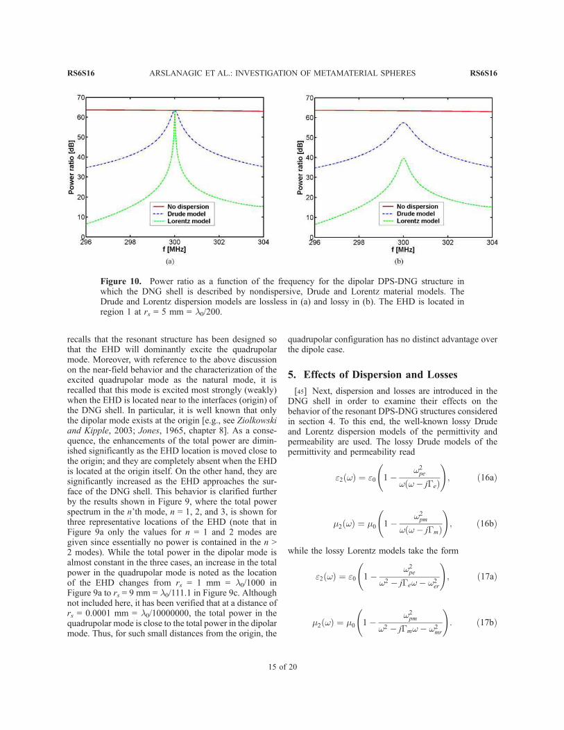
Figure 10. Power ratio as a function of the frequency for the dipolar DPS-DNG structure inwhich the DNG shell is described by nondispersive, Drude and Lorentz material models. TheDrude and Lorentz dispersion models are lossless in (a) and lossy in (b). The EHD is located inregion 1 at rs = 5 mm = l0/200.
RS6S16 ARSLANAGIC ET AL.: INVESTIGATION OF METAMATERIAL SPHERES
15 of 20
RS6S16
[46] In (16) and (17), the quantities wpe and wpm
represent the electric and magnetic plasma frequencies,Ge and Gm represent the electric and magnetic collisionfrequencies, while wer and wmr in (17) represent theresonance frequencies of the permittivity and permeabil-ity, respectively. The two models are designed to recover,at the angular frequency of operation, w0 = 2pf0 with f0 =300 MHz the lossless permittivity and permeabilityvalues given in Table 2, which were used in section 4to define the resonant DPS-DNG structures. For theDrude model, the values of wpe
2 and wpe2 are determined
from the real part of (16a) and (16b), respectively,evaluated at wo to recover the desired lossless materialparameter values. For the Lorentz model, with theassumption that the losses are small, the frequency ofoperation f0 must lie above the resonance frequency toobtain the required negative lossless material parametervalues. Since the angular frequencies of the permittivityand permeability at resonance are given by wer = 2pfer =wmr = 2pfmr = 2pfr, the frequency fr is set to fr = 290 MHz,and the values of wpe
2 and wer2 for the Lorentz model are
determined from the required values of the real parts of(17a) and (17b).[47] To investigate the effects of the dispersion and
loss, two specific cases are first considered. In the firstcase, Ge = Gm = 0 for both models, and in the secondcase, Ge = Gm = 10ÿ3 wo. Thus, the DNG shell isdispersive and lossless in the first case, while it is bothdispersive and lossy in the second case. The influence ofthese two cases on the performance of the electricallysmall dipolar DPS-DNG structure with the EHD locatedin region 1 at rs = 5 mm = l0/200 is shown in Figure 10.(The PR values given in this section are calculated forthe same resonant dipolar configuration that was treatedin section 4.2, with the exception that dispersion or/andloss are now included.) The results for the reference case,in which no dispersion occurs, are likewise included inthe figure.[48] As can be observed from Figure 10, the PR is
almost constant in the depicted frequency range when theDNG shell is treated as lossless and nondispersive, and,hence, the response is broadband. In contrast to thesenondispersive results, the bandwidth of the resonanceattained at f0 = 300 MHz is narrowed considerably wheneither of the two dispersion models is introduced into theDNG shell. Moreover, the Lorentz model results arecharacterized by an even narrower bandwidth than those
obtained with the Drude model, this being particularlythe case in the absence of losses as illustrated inFigure 10a. In the lossless dispersion cases it is importantto note that the maxima of their PR values, which occurat the resonance frequency f0 = 300 MHz, attain the samevalue as predicted for the nondispersive case. Theinclusion of loss has two basic impacts on the PR values.With reference to Figure 10b it is first noted that theresonances remain at f0 = 300 MHz, but they arebroadened relative to the lossless cases. Secondly, themaxima of the PR values at the resonance frequency f0 =300 MHz for the lossy dispersive models are lower thanthe nonlossy case value. In particular, the PR value at f0 =300 MHz in the nonlossy case is 63.43 dB, while it is57.44 dB for the lossy Drude dispersion model and39.55 dB for the lossy Lorentz dispersion model. Thedifference in the PR behavior between the two dispersionmodels was expected. The Lorentz model, which has afaster frequency variation than the Drude model near thespecified negative material values, has a much narrowerbandwidth. The losses associated with the Lorentz modelare also more severe (for the same collision frequencies)than those with the Drude model because the requirednegative values occur near its resonance frequency,where its losses are largest. In fact the values of thepermittivity and the permeability in the lossy dispersionmodels evaluated at f0 = 300 MHz are e2 = e0 (ÿ3 ÿj0.004), m2 = m0(ÿ3 ÿ j0.004) for the Drude model, ande2 = e0 (ÿ3 ÿ j0.0594), m2 = m0(ÿ3 ÿ j0.059) for theLorentz model. As a consequence, the electric andmagnetic loss tangents at this frequency, denoted andgiven by LTe = e002/je02j and LTm = m00
2/jm02j, respectively,
are LTe = LTm = 0.0013 for the Drude model and LTe =LTm = 0.019 for the Lorentz model. Thus, the loss in theLorentz model is indeed larger than that in the Drudemode, even though their collision frequency values arethe same. Similar results are obtained for the dipolarDPS-DNG structure when the EHD is located inregions 2 and 3.[49] To further illustrate the effects of loss on the
performance of the resonant dipolar DPS-DNG structure,several additional lossy, dispersionless cases were con-sidered. In particular, five lossy cases whose permittivityand permeability values (at f0 = 300 MHz) are shown inTable 3, along with the associated electric and magneticloss tangent values, were chosen for the investigation.The real parts of the material parameters were fixed at
Table 3. Five Lossy Cases for the Additional Investigation on the Effects of Loss
RS6S16 ARSLANAGIC ET AL.: INVESTIGATION OF METAMATERIAL SPHERES
16 of 20
RS6S16
the same value, while the amount of loss was varied froma very small to a very large value. In each of these cases,identical values of the relative permittivity and perme-ability were selected, thus yielding the same electric andmagnetic loss tangents. The PR as a function of the EHDlocation, rs, is shown in Figure 11a for these five lossycases. The reference lossless case, treated in section 4.2,is likewise included for comparison purposes.[50] While there is almost no difference between the
lossless case and the very small loss Case 1, there isreduction of the PR in Case 2. As more loss is includedin Cases 3 and 4, the PR values are lowered even further.They attain their lowest values for Case 5 when thelargest amount of loss is included. One finds that anappreciable amount of loss in the DNG shell suppressesthe excitation of the resonant dipolar mode. More lossfurther suppresses the interaction of the EHD with theDPS-DNG structure. Consequently, the inclusion of losshas the effect of lowering the enhancement of the totalpower. These observations are illustrated in Figure 11b,where the electric near field is given for the Case 5 lossyDPS-DNG structure when the EHD is in region 1 at rs =5 mm = l0/200. Comparing the results in Figure 11bwith the electric near field for the EHD in free spacegiven in Figure 4a, it is found that they are very similar,i.e., the Case 5 lossy DPS-DNG structure does not haveany influence on the field radiated by the EHD, thisbeing similar to the effect of the corresponding losslessDPS-DPS structure, see also Figure 4b. In other words,
the Case 5 lossy DPS-DNG structure is at most only veryweakly resonant and, therefore, it can not lead to anyappreciable enhancement of the total power.[51] It must be emphasized that only the results for the
dipolar DPS-DNG structures have been presented in thissection. Similar behavior is obtained when lossless andlossy dispersive quadrupolar, or even higher-order, DPS-DNG structures are considered. Although not includedhere, it has been shown that these higher-order structureshave significantly narrower bandwidths and are, there-fore, even more easily affected by the presence ofdispersion and losses than the dipolar DPS-DNG struc-tures are. These features observed for the concentricsphere geometry treated in this manuscript are also inevidence when the corresponding cylindrical structuresare considered [see, e.g., Arslanagic et al., 2006].
6. Wavelength-Sized Natural Resonances
[52] In the previous sections it was emphasized thatDNG materials offer advantages over the usual DPSmaterials in the design of resonant electrically smallMTM layered spheres, with significant enhancement ofthe total power. The existence of these resonances,despite the electrically small size, was attributed to theexcitation of the necessary resonant mode, which wasshown to be possible because of the presence of theDNG material. It will be demonstrated below that as thesize of the structure is increased to be on the order of a
Figure 11. Impact of the DNG material losses: (a) Power ratio as a function of the EHD location,rs, when the EHD is in region 1 for the lossless and the lossy (Cases 1-5) dipolar DPS-DNGstructures. (b) The magnitude of the �-component of the total electric near field of the dipolar DPS-DNG structure in which the DNG shell is modeled by Case 5 and the EHD is in region 1 at rs =5 mm = l0/200. In Figure 11b, the plane of observation is the xz-plane, and the field is shown in acircular region of radius 30 mm = l0/33.33.
RS6S16 ARSLANAGIC ET AL.: INVESTIGATION OF METAMATERIAL SPHERES
17 of 20
RS6S16
wavelength, the advantages of the DNG materials dis-appear, e.g., the same order of magnitude of the PRvalues are obtained for both DPS-DNG and DPS-DPSstructures. This behavior is expected and occurs when thesize of the structure enters the natural resonance regime;e.g., see Engheta and Ziolkowski [2006, chapter 2],
Alu and Engheta [2005], and Ziolkowski and Kipple[2003] for detailed explanations.[53] To illustrate this point, a DPS-DPS and a DPS-
DNG structure with the material parameters given inTable 2 are considered. The frequency of operation is f0 =300 MHz and the location, as well as the orientation, ofthe EHD is the same as in section 4. The inner radius ofregion 2 is set to r1 = 10 mm = l0/100, and the outerradius is allowed to vary in the interval r2 2 [19.5, 300]mm = [0.0195, 0.0300] l0 , corresponding to r2 valuesmuch larger than those investigated previously. Figure 12shows the PR values as a function of these r2 values. For r2approximately greater than 150 mm = l0/6.666, compa-rable values of the PR are obtained in this wavelength-sized natural resonance regime for both the DPS-DPS andDPS-DNG structures. However, for the majority of theinvestigated r2 values, the PR values for the DPS-DNGstructure are slightly above those for the DPS-DPSstructure. Nonetheless, none of the PR values inFigure 12 are on the order of the very large PRs obtainedwith the electrically small resonant dipolar, as well asquadrupolar structures, considered in section 4.
7. SNG Structures
[54] While the emphasis so far has been on the use ofDNG versus DPS materials, it is possible, as noted insection 3, to use SNG materials to achieve subwave-length-sized natural resonances. More specifically,depending on the specific configuration under examina-
Figure 12. Power ratio as a function of the outer shellradius r2 for the DPS-DNG and DPS-DPS sphericalstructures when the size of the structures is in thewavelength-sized natural resonance regime.
Figure 13. (a) Power ratio as a function of the outer shell radius r2 for the electrically smalldipolar DPS-ENG, DPS-MNG, DPS-DNG and DPS-DPS structures. (b) Power ratio as a functionof the outer shell radius as it varies in the interval r2 2 [19.5, 300] mm = [0.0195, 0.0300] l0 for theDPS-ENG and DPS-MNG structures. In both Figures 13a and 13b, the EHD is in region 1 at rs =5 mm = l0/200.
RS6S16 ARSLANAGIC ET AL.: INVESTIGATION OF METAMATERIAL SPHERES
18 of 20
RS6S16
tion, satisfaction of either of the two resonance condi-tions, i.e., (15a) or (15b), can still lead to electricallysmall resonant structures having the same enhancementproperties as those discussed with the DPS-DNG struc-tures. It is recalled that this occurs because the totalpower in (11) has resonant features when either A4,nm orB4,nm have resonant behaviors.[55] To illustrate this behavior, it is useful to examine
configurations consisting of an EHD radiating in thepresence of a dipolar DPS-ENG structure and a dipolarDPS-MNG structure. These structures are chosen to havethe same material and geometrical parameters as thedipolar DPS-DNG structure considered in section 4,except that for the DPS-ENG structure, the permeabilityin region 2 is positive and equal to m2 = 3m0 while for theDPS-MNG structure, the permittivity in region 2 ispositive and equal to e2 = 3e0.[56] Figure 13a shows the PR as a function of the outer
radius r2 for the dipolar DPS-ENG and DPS-MNGstructures having the EHD located in region 1 at rs =5 mm = l0/200. The results reported in section 4 for theDPS-DNG and DPS-DPS structures are likewise included.[57] The resonance peaks, at which significant enhance-
ments of the total power are obtained, are found for theDPS-ENG and DPS-MNG structures at the same outerradius value r2 = 18.84 mm = l0/53.08. These peaksclearly show that ENG or MNG materials may replaceDNG materials in the task of generating resonances inelectrically small MTM-based structures. These resultsare interesting and suggest that one might focus onobtaining appropriate SNG materials rather than DNGones for this particular application. It is also interesting tonote that the amplitude of the resonance peak for the DPS-ENG structure is PR � 63 dB, and is thus identical to thepeak value of PR obtained for the DPS-DNG structure insection 4.2. However, the peak PR value, PR� 21 dB, forthe resonant DPS-MNG structure is significantly lowerthan those obtained for the corresponding resonant DPS-ENG and DPS-ENG structures. Nonetheless, it is stillconsiderably higher that the PR values generated by theDPS-DPS structures. These results reflect that the domi-nant field structure in the spherical vector wave expan-sions of the fields present in the electrically small cases is,as expected, TM. Thus, a DPS-ENG structure is favouredin the presence of an EHD. Note that if the source ofelectromagnetic radiation is a magnetic Hertzian dipole,the DPS-MNG structure would be naturally favoured,since the dominant term is TE in that case. It must bestressed that the underlying mechanism for the enhance-ment of the total power when an EHD radiates in thepresence of DPS-ENG structures resembles that ofthe previously treated DPS-DNG structure. However,the resonant peaks for the two DPS-SNG cases, found atr2 = 18.84 mm = l0/53.08, are attained at a somewhat
larger value of the outer radius r2 = 18.69 mm = l0/53.50,than for the DPS-DNG structure.[58] For the SNG-based structures of larger size, the
PR as a function of r2 2 [19.5,300] mm = [0.0195,0.0300] l0 is shown in Figure 13b for both DPS-ENGand DPS-MNG structures. For the former, PR valuesabove 10 dB are obtained up to the outer radius of r2 =100 mm = l0/10 mm, while beyond this radius the PRfalls rapidly off. This is expected since the waves fromthe EHD cannot penetrate through an electrically largeENG shell in which the wave number is purely imagi-nary. This is also the case for the DPS-MNG structure,for which the blockage of the waves is emphasized ateven smaller r2 values and, thus, no enhancements areobserved. As a consequence, the significant enhance-ments of the total power by use of DPS-ENG and DPS-MNG structures are only obtained if they are electricallysmall.
8. Summary and Conclusions
[59] In this paper the properties of the canonical con-figuration consisting of an arbitrarily oriented and locatedEHD radiating in the presence of a pair of concentricMTM spheres were investigated. An analytical solution interms of spherical vector wave functions was first derived,and this was subsequently employed in a numericalinvestigation of electrically small, as well as large,MTM-based structures. The investigation is entirely the-oretical since it assumes the existence of electrically smallDNGmaterials and considers a canonical problemwith animpressed current source. Nevertheless, the resultsreported here for the power ratio correspond to a normal-ized radiation resistance and are thus of relevance for thepotential matching of generators to more realistic versionsof these radiating systems. Particular emphasis was put onthe electrically small dipolar and quadrupolar structures.In the numerical investigations, the near field spatialdistribution and the total radiated power were examined.The results for the MTM-based designs were compared tothe corresponding DPS-based designs.[60] It was demonstrated that electrically small MTM-
based structures, such as the DPS-DNG structures, canbe designed to be resonant and thereby lead to significantchanges of the field radiated by the EHD as well assignificant enhancements of the total radiated power.These enhancements were found to be due to the so-called subwavelength-sized natural resonances of theMTM-based structures. Their existence was predictedanalytically, and it was demonstrated that they do notexist for the corresponding DPS-DPS structures. It wasalso shown that changing the location of the EHD withinthe DPS-DNG structure had little impact on the totalradiated power. This is in distinct contrast to the analo-gous cylindrically-shaped configurations [Arslanagic et
RS6S16 ARSLANAGIC ET AL.: INVESTIGATION OF METAMATERIAL SPHERES
19 of 20
RS6S16
al., 2006]. Nonetheless, the spherical electrically smallresonant quadrupolar DPS-DNG structure was found toexhibit some variation of the total radiated power withthe EHD location. In particular, when the EHD is locatednear the center of the concentric spheres, the dipolarmode then dominates the interaction process. Thus,although such a resonant DPS-DNG structure wasexpected to excite the quadrupolar mode as the dominantone, it was found that other modes, such as the dipolarmode, could be excited for specific source locations.Moreover, it was found that the enhancements, althoughsignificantly narrower and more sensitive to variationsof the material and geometrical parameters, are con-siderably larger for the quadrupolar structures than forthe dipolar ones. This feature was also recognized withthe corresponding cylindrical designs in the work ofArslanagic et al. [2006].[61] The dispersive nature of the MTM material was
shown to lead to a considerable narrowing in frequencyof the resonances. Small and moderate losses did notmake the resonances disappear but were found to lowerthe peak amplitudes of the resonant enhancements.However, the inclusion of very large losses did makethe resonances disappear because of the suppression ofthe required resonant modes.[62] Furthermore, it was demonstrated that ENG and
MNG materials can offer results similar to those obtainedwith DNG materials. With the EHD, the exciting field ispredominantly TM and for this case it was found that theDPS-ENG structure posses properties comparable tothose of the DPS-DNG structure.[63] It is important to emphasize that the electrically
small resonant DPS-DNG structures investigated in thiswork give rise to a total radiated power comparable toand even exceeding those of electrically larger structures.For the latter, it was found that both DPS-DPS and DPS-DNG structures lead to resonant behaviors.
References
Abramowitz, M., and I. A. Stegun (1965), Handbook of Math-
ematical Functions, Dover, Mineola, N. Y.
Alu, A., and N. Engheta (2004), Guided modes in a waveguide
filled with a pair of single-negative (SNG), double-negative