3 Artificial Materials based Microstrip Antenna Design Merih Palandöken Berlin Institute of Technology Germany 1. Introduction The demand on the portable mobile devices is increasing progressively with the development of novel wireless communication techniques. In that respect, novel design methods of wireless components have to be introduced to fulfill many performance criteria simultaneously. Compact size, light weight, low profile and low cost are now quite important challenges for a system designer to accomplish in the design and performance enhancement of every wireless mobile component. One of these wireless components to be enhanced inevitably and matched with these new challenges in any communication system is the antenna. Therefore, this chapter is mainly dealing with the novel antenna design method, which is based on artificial materials. How to engineer artificially the ground plane, substrate or radiating part of the antenna as a solution for better antenna designs are explained from basic electrical limitations upto proposed design solutions. In this chapter, basic concepts in electrically small antennas are introduced in Section 2 to determine the fundamental performance limitations of small antennas. The minimum Q and maximum gain of electrically small antennas, which are the main targets in the antenna design, are addressed to point out the effect of electromagnetic material parameters and physical dimensions on the antenna radiation performance. In Section 3, the concept of electromagnetic parameter engineering and how to engineer substrate effective parameters are introduced along with the design of broadband artificial material loaded dipole antenna in detail as a design example to understand how to combine these artificial materials with the radiating sections for better antenna performance than conventional alternative designs. In Section 4, rather than manipulation of effective parameters of substrate, the concept of artificial ground plane, like high impedance surface (HIS), electromagnetic bandgap structures (EBG) for more directive and high gain antennas is explained with a numerical example of the design of electrically small artificial magnetic conductor (AMC) ground plane. In the last section, in the microstrip antenna design with artificial materials, the radiating part of the antenna is structured with electrically small self-resonant cells to design electrically smaller, higher gain antennas in a certain physical dimension than the conventional antennas. Each above mentioned concepts are detailed with pioneering references for more interested readers. www.intechopen.com
Transcript
3
Artificial Materials based Microstrip Antenna Design
Merih Palandöken Berlin Institute of Technology
Germany
1. Introduction
The demand on the portable mobile devices is increasing progressively with the
development of novel wireless communication techniques. In that respect, novel design
methods of wireless components have to be introduced to fulfill many performance criteria
simultaneously. Compact size, light weight, low profile and low cost are now quite
important challenges for a system designer to accomplish in the design and performance
enhancement of every wireless mobile component. One of these wireless components to be
enhanced inevitably and matched with these new challenges in any communication system
is the antenna. Therefore, this chapter is mainly dealing with the novel antenna design
method, which is based on artificial materials. How to engineer artificially the ground plane,
substrate or radiating part of the antenna as a solution for better antenna designs are
explained from basic electrical limitations upto proposed design solutions.
In this chapter, basic concepts in electrically small antennas are introduced in Section 2 to
determine the fundamental performance limitations of small antennas. The minimum Q and
maximum gain of electrically small antennas, which are the main targets in the antenna
design, are addressed to point out the effect of electromagnetic material parameters and
physical dimensions on the antenna radiation performance. In Section 3, the concept of
electromagnetic parameter engineering and how to engineer substrate effective parameters
are introduced along with the design of broadband artificial material loaded dipole antenna
in detail as a design example to understand how to combine these artificial materials with
the radiating sections for better antenna performance than conventional alternative designs.
In Section 4, rather than manipulation of effective parameters of substrate, the concept of
artificial ground plane, like high impedance surface (HIS), electromagnetic bandgap
structures (EBG) for more directive and high gain antennas is explained with a numerical
example of the design of electrically small artificial magnetic conductor (AMC) ground
plane. In the last section, in the microstrip antenna design with artificial materials, the
radiating part of the antenna is structured with electrically small self-resonant cells to design
electrically smaller, higher gain antennas in a certain physical dimension than the
conventional antennas. Each above mentioned concepts are detailed with pioneering
references for more interested readers.
www.intechopen.com
Microstrip Antennas
44
2. Fundamental limits of small antennas
Electrically small antenna design has long been the current trend as one of the most significant and interested research topics in microwave community. The large physical dimensions of conventional ┣/2 dipole or ┣/4 monopole antennas in the short-, or long-wave radio communication has further triggered to miniaturize the antenna dimensions in new generation applications. Especially, nowadays the demand on multifunctional complex systems imposes to design miniaturized mobile terminals with a predetermined bandwidth. One of the challenging issue in the design of these mobile systems is to miniaturize their radiating parts with a prerequired gain for data transmission and navigation. The small antennas have an additional advantage, especially in wireless/contactless measurement systems,of not to influence the measured field for more reliable measurements. Hence, to design compact, high efficient/gain, broadband antennas is the current challenge to be overcome for any high performance wireless systems. An electrically small antenna is commonly defined as an antenna occupying a small fraction of one radiansphere, which circumscribes the maximum dimension of the antenna (Wheeler, 1975;Wheeler, 1959;Wheeler, 1947;Johnson,1993). The radianphere is by definition the spherical volume having the radius of ┣/ 2┨. This defines logically the maximum dimension to be smaller than ┣/┨, 0.314┣ where ┣ is the free space wavelength. A conventional upperlimit for the greatest dimension is less than one-quarter wavelength (including any image resulting from the ground plane), which is approximately 0.785 times radius of the radiansphere. This results the electrically small antenna to have maximum ka value of 0.78, where k is the free space wave number and a is the radius of the imaginary enclosing sphere. The main reason to have the radiansphere as a logical reference in the above definition is that because around a small antenna, this volume is the space occupied mainly by the stored energy of its electrical or magnetic field for the electrical dipole and magnetic dipole respectively. This region is also termed as reactive near field region. The radius of the enclosing radiansphere is also the distance at which the reactive part of the input impedance is equal to the real part for infinitesimally small electric and magnetic dipole. Far distances away from this radius, the real part is more dominating than the imaginary part, leading to have more plane wave formed wave propagation like in the transition from Fresnel to Fraunhofer regime. Thus, an electrically small antenna is essentially a capacitive electric or inductive magnetic dipole or possibly a self resonant antenna, which is the combination of both types. The operation bandwidth of any antenna type can be determined by the frequency
dependence of feed point impedance, which is calculated by the surface integration of
transversal field components over the spherical surface of radius a. The feed point
impedance is given by Z(ω) = R(ω) + j X(ω), where ω is the radian frequency. The resistive
part of input impedance includes both the radiation and conduction loss. The imaginary
part is proportional to the difference of time averaged stored magnetic and electric energy
outside the spherical volume of radius a. This could be easily deduced from the following
Poynting formulation,
( ) ( )2 2* * 2
S V V
1 1 1 1 1ExH �dA=j2ω ┤ H - ┝ E dV+ E�J dV I Z(ω)
2 4 4 2 2
⎛ ⎞− =⎜ ⎟⎝ ⎠∫ ∫ ∫iiij iijifij¶ (1)
The impedance bandwidth of matched small antennas is often characterized by its Q at the resonant frequency, which has an achievable theoretical lower bound and inversely
www.intechopen.com
Artificial Materials based Microstrip Antenna Design
45
proportional to the respective fractional bandwidth. Therefore, no electrically small antenna can exhibit a Q less than its theoretical lower bound or bandwidth larger than a specific upper bound. The antenna Q is generally defined as, in (2), where We and Wm are time averaged stored electric and magnetic energy outside the enclosing sphere of radius a,
respectively and lossP is the sum of total radiated and metallic loss power at the resonance
frequency, 0ω .
e0 e m
loss
m0 m e
loss
W2ω , W >W
PQ =
W 2ω , W >W
P
⎧⎪⎪⎨⎪⎪⎩ (2)
This formulation is actually the same formulation, which could be derived from Poynting formulation in (1) by taking the ratio of imaginary and real part of complex power for high Q antennas. In the theoretical lower bound calculation of Q, an arbitrary current distribution is optimized to excite all possible higher order orthogonal spherical TM modes with respective rotation symmetrical modal near fields for a vertical wire antenna. The modal Qn of vertically oriented omnidirectional antenna can be calculated in the terms of modal tangential field quantities on the spherical surface of the reactive near field region of radius a as (Chu,1948),
( ) ( )2n n
n n nn
-2n n n n n n
2ωW 1 dXQ = = ┩h ┩ -X
P 2 d┩
X = ┩j ┩j ' + ┩n ┩n ' ┩h
⎡ ⎤⎢ ⎥⎣ ⎦⎡ ⎤⎣ ⎦
(3)
where hn is the nth order spherical Hankel function of second kind, which is defined as hn=jn- jnn , ┩ is ka, which is calculated on a spherical closed surface. The antenna Q resulting from the spherical wave function expansion method is lower than the real value since the stored energy inside the sphere has been totally ignored in the calculation. The above relation is plotted in Figure 1. As it could be understood from Figure 1, for a specific operation frequency and excited mode of electrically small antenna, to increase the antenna’s maximum dimension 2a or its physical volume, reduces the total stored energy outside the antenna volume along with the increase in the radiation resistance, hence Qn.
.The reason of reduction in the amount of stored energy or increase in the radiation resistance could be deduced by the introduction of additional radiating sections which enhances the specific mode to propagate with real impedance and less reactive part. Especially, for electrically small antennas, to increase the antenna length leads the excited near field to be more bounded in the antenna volume due to the small ratio of reactive near
field region radius, 3D
0.62┣
to antenna size. This results modal stored energy, which is
calculated in the spherical volume outside the radius a, to be reduced. On the other hand, higher order modes result the antenna to have higher Q for the specific size. Thus, to excite higher order modes is in practice quite challenging due to the difficulty in matching high reactive input impedance. The main conclusion to be conducted in minimum Q calculation is that Q is only to be minimized under one mode excitation of the
www.intechopen.com
Microstrip Antennas
46
Fig. 2.1. Qn of the equivalent circuit of TMn or TEn wave (Chu,1948)
antenna without multimodal operation. Since Q1 has the lowest amplitude, the antenna which generates a field outside the sphere corresponding to that of an infinitesimally small dipole has potentially the broadest bandwidth of all antennas (Chu, 1948). Therefore, the optimum method to obtain broadbandwidth operation for a specific antenna size is to operate the antenna with lowest of all possible modes. The theoretical lower bound of Q for small directional and omnidirectional antennas is expressed as (Geyi, 2003)
( )minsmall 3
1 1Q = +
ka2 ka
⎛ ⎞⎜ ⎟⎜ ⎟⎝ ⎠ (4)
In general, for a tuned antenna of any size exhibiting a single resonance frequency, Q can be calculated from the input feeding impedance as (Yaghjian & Best,2005)
2
0200 0 0
0 0
X(ω )ωQ(ω ) = R'(ω ) + X'(ω )+
2R(ω ) ω⎛ ⎞⎜ ⎟⎜ ⎟⎝ ⎠ (5)
where 0R'(ω ) and 0X'(ω ) are the frequency derivatives of real and imaginary parts of feed
point impedance of unmatched antenna at the resonance frequency. As it can be deduced
from the formulation, Q can be minimized with higher radiation resistance, for instance, by
the design of self-resonating elements, which has an additional advantage of compensated
reactive part, 0X(ω ) =0 to minimize the numerator term and increase the antenna overall
gain and efficiency without introducing any conduction loss due to the matching network. It
is an important issue because it is generally known that in electrically small antennas the
loss resistance within the matching network often exceeds the radiation resistance, resulting
www.intechopen.com
Artificial Materials based Microstrip Antenna Design
47
in low overall efficiency. The efficiency reduction in mismatch loss achieved with the
impedance match often exceeds the increase in loss due to the matching components and
better overall performance is achieved relative to the isolated mismatched antenna. Thus,
one strategy in the antenna design could be to design self resonating structures to increase
the radiation resistance and enhance the operation bandwidth in comparison to the non
resonating capacitive or inductive antennas. 0R'(ω ) in (5) is mostly quite small in
comparison to the other terms. However for the case of gain optimization, it is well known that there is no mathematical
limit to the gain to be obtained from currents confined to an arbitrary small volume
(Chu,1948). But a small sized antenna with extremely high gain produces high field intensity
in the vicinity of the antenna, which results in high heat loss or high stored energy. This
leads the antenna gain to be limited with an upper bound. The maximum gain obtainable is
calculated as Gmax= N(N+2) by artificially truncating the spherical wave function
expansions of the fields to the order N (Harrington, 1960). Hence as N increases
(equivalently the antenna complexity increases) the maximum gain and practical difficulty
in the matching network of high reactive antenna increases. Therefore, in principle, the main
target is to excite higher number of modes in the antenna by imposing the specified
optimum current distribution, which increases the radiation resistance and hence gain.
However, as it is stated, this leads in turn these higher order modes to attenuate more in
comparison to the lower order modes as the evanescent fields, leading large stored energy
in comparison to the radiation loss. This could be quite easily deduced in analogy to the
reduction of propagation constant with the higher order modes in dielectric waveguides,
which increases the leaking power of the guided field from the substrate to the free space,
hence radiated power. In other words to express, the gain enhancement with the account of
high number of in-phase excited modes and hence the superposition of radiated field of
each mode could counteract to the amount of stored energy in the near field, because they
could not propagate effectively into the free space. It is because that these evanescent waves
have pure capacitive or inductive impedance depending on the excitation of TM or TE
modes, respectively.
Therefore, due to the trade-off between gain and Q of an antenna, there is one additional parameter to be maximized for optimum antenna design. This parameter is the ratio of gain (G) to Q. The maximum G/Q ratio for the small antennas is expressed as,
small 3
2dir
small 3
2omni
G 6(ka)max
Q 2(ka) +1
G 3(ka)max
Q 2(ka) +1
≈
≈ (6)
Antenna gain can be alternatively expressed with an additional parameter called radiation power factor (PF) in terms of antenna input impedance (Wheeler, 1947). It is descriptive of the radiated power from an electrically small antenna taking a much larger value of reactive power. This term is applicable to either kind of electrically small electric or magnetic reactor, and its small value is limited to some measure of the physical size in either kind. It is equal
www.intechopen.com
Microstrip Antennas
48
to 1/Q and defined as the ratio of input resistance to reactance at the resonant frequency. For any shape of electrically small antenna, the radiation PF at one frequency is proportional to its volume. Moreover, it is nearly equal for electric and magnetic dipole type radiators of nearly equal volume. However, radiation PF is somewhat different from the radiation parameters, which have been calculated before. The main difference is that in principle the effective volume of any small electric or magnetic antenna is determined by mapping the near field distribution of the antenna around the radiansphere to that of the equivalent circular capacitor shaped electric and spiral inductor formed magnetic antenna, which has not been done in previous calculations. The integration volume in the calculation of previously described parameters is the volume outside the smallest sphere enclosing the antenna, which is unbounded, in contrast to that, for radiation PF calculation, the reference volume is the volume inside the radiansphere, which is clearly bounded. The radiation PF can be alternatively defined in terms of effective volume V' and volume of radiansphere V as (Wheeler, 1947; Johnson,1993 )
3
2 V' 2 2┨a'p= =
9 Vs 9 ┣⎛ ⎞⎜ ⎟⎝ ⎠ (7)
Thus, one method to enhance the radiation PF of small antenna is to increase the effective volume of electric or magnetic dipoles by decreasing electric permittivity of dielectric or increasing magnetic permeability of inductive core, respectively. The logical approach of this method is to eliminate or minimize the avoidable stored energy inside the magnetic or electric core by leaving unavoidable amount of stored energy outside the capacitor or inductor core but mostly inside the radiansphere. The accompanying enhancement of radiation resistance with decreasing permittivity and increasing permeability is also consistent with the medium parameter dependence of radiation resistance of Hertzian electric and magnetic dipoles. After having pointed out the influence of material parameters on the antenna performance, how to engineer the substrate material to design broadband microstrip dipole antenna is explained with numerical simulations in the next section.
3. Artificial substrate design
Metamaterials are artificially structured materials providing electromagnetic properties not encountered in nature (Veselago, 1968; Engheta & Ziolkowski, 2006, Caloz & Itoh, 2005, Eleftheriades & Balmain, 2005). The electrodynamics of hypothetical materials having simultaneously negative permittivity and permeability was first theoretically predicted by Veselago (Veselago, 1968). These materials are termed as “left handed materials (LHM) “ due to the left-handedness of electric, magnetic field and wave vector. A left handed material was first implemented in a two dimensional periodic array of split ring resonators and long wire strips by Smith (Smith et al., 2000). The logical approach was to excite the split ring resonators and wire strips in order to force the structure to behave like magnetic and electric dipoles, respectively. Since then, there have been large numbers of experimental investigations on the observation of this phenomenon. The effective electromagnetic parameters were also retrieved experimentally and numerically from the transmission and reflection data (Chen et al., 2006; Smith et al., 2005; Alexopoulos et al., 2007; Smith et al., 2000). Rather than split ring resonators and wire strips, the left handed feature can also be
www.intechopen.com
Artificial Materials based Microstrip Antenna Design
49
realized with periodic loading of conventional microstrip transmission lines with series capacitors and shunt inductors [12],[20]. Many microwave circuits have been implemented by using this strategy such as compact broadband couplers, broadband phase shifters, compact wideband filters, compact resonator antennas, LH leaky wave antennas, which have a very unique property of backfire-to-endfire frequency scanning capability with broadside radiation, which is not possible for RH leaky wave antennas (Caloz & Itoh, 2005, Eleftheriades & Balmain, 2005). In this section, the design of a novel microstrip dipole antenna by artificially engineering the substrate material with left-handed metamaterials (LHM) is explained for compact wideband wireless applications. The broadband microstrip antenna is composed of a dipole and six LHM unit cells. The antenna is matched to 50Ω with the stepped impedance transformer and rectangular slot in the truncated ground plane. By the utilization of phase compensation and coupled resonance feature of LHMs, the narrowband dipole antenna is operated at broader bandwidth. First in Section 3.1, the structure of the electrically small LHM unit cell is described. A one dimensional dispersion diagram is numerically calculated by Finite Element Method (FEM) to prove the lefthandedness and respective negative refractive index of the proposed unit cell. The effective permittivity and permeability are also retrieved from the reflection and transmission data of one unit cell. In Section 3.2, the configuration and operation principle of the proposed antenna are explained. The simulated and measured return loss, radiation pattern and numerically computed radiation parameters are presented.
3.1 LHM unit cell design
The negative material parameters are synthesized by the simultaneous excitation of electric and magnetic dipoles in the LHM unit cell. The original structure proposed in (Smith et al., 2000) consists of a bulky combination of metal wires and split ring resonators (SRR) disposed in alternating rows. The excited wires and SRRs are electric and magnetic dipoles, thus creating the left-handed behavior. Because the typical LHM designs are inherently inhomogeneous, novel strategies to miniaturize the unit cell with different topological and geometrical methods are important.
3.1.1 Description of the structure LHM behavior implies small unit cells as compared to the free space wavelength ┣o. The upper limit of the unit cell size is one fourth of the guided wavelength (Caloz & Itoh, 2005). One well-known method of miniaturization is to increase the coupling between the resonators. This strategy was chosen for the proposed LHM unit cell, Figure 3.1 with geometrical parameters in (Palandöken et al. 2009), in which wire strips and spiral resonators (SR) are directly connected with each other, on both sides of the substrate. Further, instead of SRRs as in the original proposals, SRs are used, which have half the resonance frequency of SRRs (Baena et al., 2004). In the design, the geometrical parameters of the front and back side unit cells are the same, except shorter wire strip length on the front side. Different strip wire lengths lead to a smaller resonance frequency and larger bandwidth. The substrate material is nonmagnetic FR4-Epoxy with a relative permittivity of 4.4 and loss tangent of 0.02. The unit cell size is 3x3.5 mm. The validity of the model is shown by retrieving the effective constitutive parameters from S parameters and by the opposite direction of group and phase velocity.
www.intechopen.com
Microstrip Antennas
50
(a) (b)
Fig. 3.1. LHM unit cell geometry. (a) Front and (b) back side of one LHM unit cell
3.1.2 Simulation results
To determine the frequency interval of left-handedness, a one dimensional Brillouin diagram is studied at first. In order to obtain the dispersion relation of the infinite periodic structure, the cells must be excited with the magnetic field perpendicular to the SR plane (z-direction), and the electric field in the direction of strip wires (x-direction), Figure 3.1. Therefore, the eigenfrequencies of a unit cell are calculated with perfect magnetic boundaries (PMC) in z-direction and perfect electric boundaries (PEC) in x-direction. Periodic boundary conditions (PBC) are imposed in y-direction. The simulation was done with the FEM based commercial software HFSS and is shown in Figure 3.2. Oppositely directed phase and group velocities are observed in the LH band between 2.15-2.56 GHz with 410MHz bandwidth, which proves additionally the negative refractive index of the proposed unit cell. Alternatively, the same unit cell structure but with longer strip wires on the front side leads to higher cutoff frequencies (2.58-2.65 GHz) and a narrow LH passband
Fig. 3.2. Dispersion diagram of the proposed LHM structure
www.intechopen.com
Artificial Materials based Microstrip Antenna Design
51
(69.7MHz). Also, if the front and back side are chosen identically, the LH passband is between 3.45-3.51 GHz, which is relatively narrow and which is at higher frequencies than for the proposed design. This explains the use of a shorter wire strip on the front side of the substrate, which reduces the resonance frequency and increases the bandwidth. In addition to the dispersion diagram, the effective constitutive parameters are retrieved from the scattering parameters of a one cell thick LHM sample. Therefore, the lefthandedness of the unit cell is not only proved with the opposite phase and group velocities as in Figure 3.2, but also with the values and the sign of the retrieved parameters. The reflection and transmission parameters are numerically calculated for x polarized and in y-direction propagating plane waves. PEC and PMC boundary conditions are imposed in x- and z- direction. The effective permittivity and permeability are retrieved from the simulated S parameters and shown in Figure 3.3.
(a)
(b)
Fig. 3.3. Real (solid) and imaginary (dashed) part of retrieved effective parameters of LHM: (a) complex permittivity, (b) complex permeability
www.intechopen.com
Microstrip Antennas
52
Therefore, by the introduction of metallic inclusions as wire strips and SRs on the substrate,
permittivity and permeability of the material, composed of periodical arrangement of these
cells can be engineered. This is the main motivation in the performance enhancement of
antennas due to the controllable manipulation of substrate parameters. There are important
issues to be discussed about the frequency dispersion of retrieved parameters. First of all,
the retrieval procedure leads in general to satisfying results – an expected Lorentzian type
magnetic resonance for µ – but unphysical artifacts occur such as a positive imaginary part
of ┝. The reason is that the homogenization limit has not been reached (Smith et al., 2005),
although the unit cell is approximately 1/23 of the guided wavelength in the substrate. The
anti-resonance of the real part of ┝ near 1.8 GHz leads consistently to a positive imaginary
part. This is an inherent artifact for inhomogeneous, periodic structures because of the finite
unit cell size. Secondly, there is a LH resonance near 1.94 GHz, which is smaller than the
lower cutoff frequency in the Brillouin diagram and is attributed to the single cell
simulation. The Bloch impedance of the infinitely periodic LHM is no longer valid for an
isolated single cell. Recently, a new parameter retrieval procedure, which is based on two-
port network formulation of one unit cell thick sample and virtual continuation of one cell
periodically into infinite number of unit cells in the propagation direction by Bloch Theorem
is introduced (Palandöken & Henke, 2009). This method will be detailed in Section 4. The
LH band for retrieved parameters extends from 1.75 up to 2.55 GHz. It is in good
correspondence with the simulated band in the range from 2.17 to 2.53 GHz in terms of the
refractive indices calculated directly from the dispersion diagram in Figure 3.2.
The size of a unit cell is approximately 1/43 of ┣o at 2 GHz, which is directly connected, in first approximation and neglecting all coupling, to the total metallic length from the open circuited SR to the short circuited wire strip. The varying degree of coupling between the resonators shifts and broadens the transmission band. If the electrically small unit cells are excited by their eigencurrents, they represent effective radiating elements and are key elements for the future aspects in the antenna miniaturization.
3.2 Antenna design 3.2.1 Operation principle
The operation principle of the antenna depends on the radiation of the dipole antenna and the excitation of LHM unit cells with the dipole field. The excitation of LH cells in their eigenmodes causes the individual electric and magnetic dipoles to be coupled in the same way as in the eigenmode simulation. These unit cell dipoles are also radiation sources in addition to the exciting dipole antenna even though they are designed as loads for the dipole. The magnetic and electric dipole moments are expressed by the surface current density as in (Li et al., 2006). For each unit cell, the electric and magnetic dipoles are simultaneously excited in principle. However, the magnetic dipoles are more effective than the electric ones. At first, magnetic dipole fields do not cancel in the far field because of inplane electrical coupling among the cells on the front and back side. The second reason is that the current on the back side strip wire has partially opposite directions and do not excite the electric dipole as effectively as the magnetic dipole. As a last reason, the surface current on the back side unit cell spirals in the same direction as the surface current on the front side unit cell, thus doubling the magnetic dipole moment. In that respect, front and back side cells are mainly magnetically coupled and the back side cells can be considered as the artificial magnetic ground plane for the front side cells, which will be discussed in
www.intechopen.com
Artificial Materials based Microstrip Antenna Design
53
Section 4. It also follows from the Lorentzian type magnetic resonance in Figure 3.3.b, which is the dominating resonance in the retrieved effective parameters. However, the antenna radiates mainly in the dipole mode, which is the reason why we call it as an LHM loaded dipole antenna.
3.2.2 Antenna design
As a first step in the antenna design, the front and back side unit cells were connected symmetrically with adjacent cells in x-direction and periodically in y-direction, see Figure 3.1. These requirements follow from the boundary condition in the eigenmode simulation. Six unit cells were used without vertical stacking and arranged in a 2x3 array, Figure 3.4. The front sides of unit cells are directly connected to the dipole in order to increase the coupling from the dipole to the LH load. In that way, the impedance of the LH load is transformed by the dipole. The truncated ground plane leads to a decreased stored energy because of lower field components near the metallic interfaces (decreased effective permittivity).The effect of the slot can be modeled by a shunt element consisting of a parallel LC resonator in series with the capacitance. The width of the slot is appreciably smaller than half a wavelength in the substrate and is optimized together with the length. Geometrical parameters are given in (Palandöken et al., 2009). The overall size of the antenna is 55x14 mm, while the size of main radiating section of the loaded dipole is 30x14 mm.
Fig. 3.4. (a) Top, (b) bottom geometry of the proposed antenna.
3.2.3 Experimental and simulation results
The return loss of the antenna was measured with the vector network analyzer HP 8722C and is shown in Figure 3.5 together with the simulation result.
www.intechopen.com
Microstrip Antennas
54
Fig. 3.5. Measured (solid line) and simulated (dashed line) reflection coefficient of the proposed antenna
The bandwidth of 63.16 % extends from approximately 1.3 GHz to 2.5 GHz with the center frequency of 1.9 GHz. Two unit cell resonances can be clearly observed in the passband. The low frequency ripples are attributed to the inaccurate modeling of the coax-microstrip line transition due to the inherent uncertainty of substrate epsilon. In summary, the measured and simulated return losses are in good agreement. There are nevertheless some issues to be discussed from the measured and simulated
results. First of all, in the experimental result, there are lower resonance frequencies than
those of the LH passband in Figure 3.2, which is also the case in the simulated return loss.
These lower resonance frequencies are due to the direct coupling between the dipole
antenna and LHM unit cells and are not emerging from the LHM resonances. In order to
prove this reasoning, the current distribution in LHM cells and the dipole is examined. At
1.7GHz, the dipole is stronger excited than the LHM cells, which is obvious because the
resonance of the LH load is out-of-band. In other words, the LH load impedance is
transformed by the dipole to match at this lower frequency. Secondly, the bandwidth is
enhanced by the fact that different sections of LHM cells and dipole are excited at different
frequencies. Still, the effect of the LH load is quite important for broadband operation. It is
because the unit cell resonances are closer to each other at the lower frequencies than at
higher frequencies. This unique property results in a broadband behavior at low
frequencies, which is not the case for RH operation. The same reasoning can also be
deduced from the dispersion diagram in Figure 3.2. Therefore, the coupled resonance
feature of LHM cells results in an antenna input impedance as smooth as in the case of
tapering. It is the main reason why the antenna is broadband (Geyi et al., 2000). The
topology of the matching network is as important as the broadband load for the wideband
operation. The third important issue is the radiation of electrically small LHM cells. It could
be verified not only from the current distribution and the return loss but also from the
radiation pattern, which is explained next. The antenna matching can be explained by the
www.intechopen.com
Artificial Materials based Microstrip Antenna Design
55
phase compensation feature of LHM as for instance in the case for the length independent
subwavelength resonators (Engheta & Ziolkowski, 2006) and antennas (Jiang et al., 2007).
The normalized radiation patterns of the antenna in y-z and x-z planes at 1.7 GHz and 2.3 GHz are shown in Figure 3.6. They are mainly dipole-like radiation patterns in E and H planes, which is the reason to call the antenna an LHM loaded dipole antenna. The radiation of the electrically small LHM cells is also observed from the radiation pattern at 2.3 GHz. As it is shown in Figure 3.6.b, the more effective excitation of the LHM cells at 2.3 GHz than at 1.7 GHz results in an asymmetric radiation pattern because of the structure asymmetry along the y axis. The cross polarization in the y-z plane is 8 dB higher at 2.3 GHz than that at 1.7 GHz, see Figure 3.2, because of LH passband resonance.
Fig. 3.6. Normalized radiation patterns cross-polarization (o-light line ) and co-polarization (+ - dark line) at 1.7 GHz in (a) y-z and (c) x-z plane, and at 2.3 GHz in (b) y-z and (d) x-z plane
www.intechopen.com
Microstrip Antennas
56
The gain of the broadband antenna is unfortunately small. The maximum gain and directivity are -1 dBi and 3 dB with 40% efficiency at 2.5 GHz, respectively. For the comparison of the overall size and radiation parameters of the proposed design with conventional microstrip dipole antennas, two edge excited ┣/4 and ┣/2 dipole antennas are designed and radiation parameters are tabulated along with the frequency dependent efficiency and gain of the proposed LHM loaded dipole in (Palandöken et al., 2009). The proposed antenna has relatively better radiation performance than these conventional dipole antennas. In addition, the gain of the proposed antenna is higher than different kinds of miniaturized and narrow band antennas in literature (Skrivervik et. al, 2001; Iizuka & Hall, 2007; Lee et al., 2006; Lee et al., 2005). On the other hand, instead of loading a narrow-band dipole with a number of LHM unit cells to broaden the bandwidth, there are well-known alternative design techniques, some of which are increasing the thickness of the substrate, using different shaped slots or radiating patches (Lau et al., 2007), stacking different radiating elements or loading of the antenna laterally or vertically (Matin et al., 2007; Ooi et al., 2002), utilizing magnetodielectric substrates (Sarabandi et al., 2002) and engineering the ground plane as in the case of EBG metamaterials (Engheta & Ziolkowski, 2006). The main reasons of low antenna gain are substrate/copper loss and horizontal orientation of the radiating section over the ground plane. It is like in the case of gain reduction of the dipole antenna with the smaller aperture (angle) between two excited lines. However, the gain can be increased by orienting the radiating element vertically to the ground plane to have same direction directed electric dipoles, unfortunately with the cost of high profile. Hence, a frequently addressed solution to decrease the antenna profile with the advantage of higher gain is to design artificial magnetic ground plane, on which the electric dipole can be oriented horizontally with the simultaneous gain enhancement, whose design is the main task of the next section.
4. Artificial ground plane design
In general, the performance of low profile wire antennas is degraded by their ground plane backings due to out-off phase image current distribution especially when the antenna is in close proximity to the ground plane. If the separation distance between the radiating section of the antenna and ground plane is ┣/4, the ground plane reflects the exciting antenna radiation in phase with approximately 3 dB increase in gain perpendicular to ground. The problem, however, is that if the ground plane-antenna separation distance is smaller than ┣/4, it cannot provide 3 dB increase, because the reflected antenna back-radiation interferes destructively with the antenna forward-radiation. Therefore, the antenna can be attributed in this case to be partially “short circuited”. A second problem in microstrip antenna design is the generation of surface waves due to the dielectric layer. In surface wave excitation, the field distribution on the feeding line and the near field distribution of the antenna excite the propagating surface wave modes of ground-substrate-air system. This results the radiation efficiency degradation due to the near field coupling of antenna to the guided wave along the substrate, which does not actually contribute to the antenna radiation in the desired manner. Additionally, the guided waves can deteriorate the antenna radiation pattern by reflecting from and diffracting at the substrate edges and other metallic parts on the substrate. To solve these problems a Perfect Magnetic Conductor (PMC) would be an ideal solution for low profile antennas on which the input radiation reflects without a phase-shift
www.intechopen.com
Artificial Materials based Microstrip Antenna Design
57
due to high surface impedance. A PMC can be designed by introducing certain shaped metallic inclusions on the substrate surface to have resonances at the operation frequency. These surfaces are called EBG surfaces or Artificial Magnetic Conductors (AMC) (Goussetis et al., 2006; Engheta & Ziolkowski, 2006). There are two bandgap regions in EBG structures. The first one is caused as a result of EBGs array resonance and array periodicity. This is the region where surface waves are suppressed and reflected due reactive Bloch impedance and complex propagation constant of the periodic array. The second region is caused by the cavity resonance between the ground plane and high impedance surface (HIS) on which radiating waves are reflected with no phase shift as in the case of PMC. The most commonly known EBG surface is the mushroom EBG (Sievenpiper et al., 1999). It consists of an array of metal patches, each patch connected with a via to ground through a substrate. The capacitively-coupled metal patches and inductive vias create a grid of LC resonators. A planar EBG can also be designed, which does not have vias and acts as a periodic frequency selective surface (FSS). A widely used EBG surface of this kind is the Jerusalem-cross (Yang et al, 1999), which consists of metal pads connected with narrow lines to create a LC network. Advanced structures without vias, consisting of square pads and narrow lines with insets, have also been proposed which are simpler to fabricate (Yang et al, 1999). On the other hand, split-ring resonators have also been frequently used in AMC design (Oh & Shafai, 2006). When the exciting magnetic field (H) is directed perpendicular to the SRR surface, strong magnetic material-like responses are produced around its resonant frequencies, thus resulting its effective permeability to be negative. However, another possibility is to excite SRRs with the magnetic field parallel to the SRRs, which results the effective permittivity to be negative rather than effective permeability. The possibility of using SRRs for the PMC surface where the magnetic vector H was normal to the rings surface or the propagation vector k perpendicular to the rings surface with the magnetic field vector H parallel to the surface was investigated (Oh & Shafai, 2006). In this section, the design of an electrically small fractal spiral resonator is explained as a
basic unit cell of an AMC. In Section 4.1, the geometry of one unit cell of periodic artificial
magnetic material is introduced. In Section 4.2, the magnetic resonance from the numerically
calculated field pattern is illustrated along with the effective permeability, which is
analytically calculated from the numerical data in addition to the dispersion diagram. The
negative permeability in the vicinity of resonance frequency validates the proposed design
to be an artificial magnetic material.
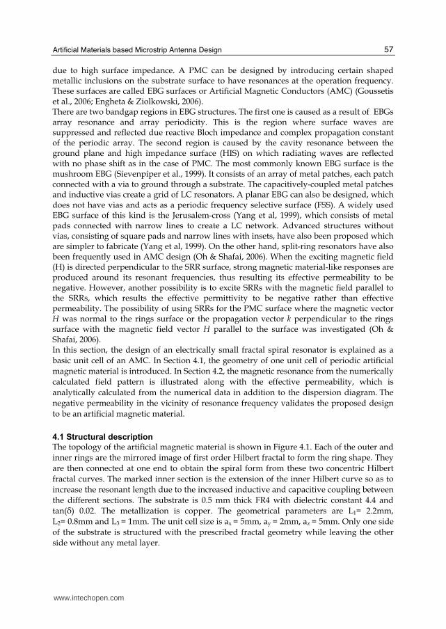
4.1 Structural description
The topology of the artificial magnetic material is shown in Figure 4.1. Each of the outer and
inner rings are the mirrored image of first order Hilbert fractal to form the ring shape. They
are then connected at one end to obtain the spiral form from these two concentric Hilbert
fractal curves. The marked inner section is the extension of the inner Hilbert curve so as to
increase the resonant length due to the increased inductive and capacitive coupling between
the different sections. The substrate is 0.5 mm thick FR4 with dielectric constant 4.4 and
tan(├) 0.02. The metallization is copper. The geometrical parameters are L1= 2.2mm,
L2= 0.8mm and L3 = 1mm. The unit cell size is ax = 5mm, ay = 2mm, az = 5mm. Only one side
of the substrate is structured with the prescribed fractal geometry while leaving the other
side without any metal layer.
www.intechopen.com
Microstrip Antennas
58
Fig. 4.1. Magnetic metamaterial geometry
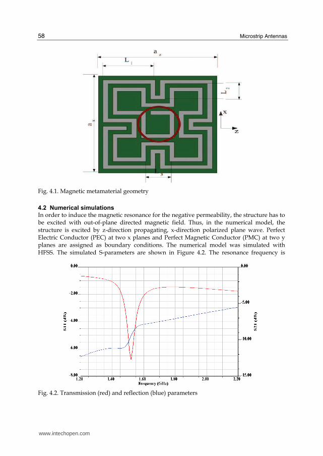
4.2 Numerical simulations
In order to induce the magnetic resonance for the negative permeability, the structure has to be excited with out-of-plane directed magnetic field. Thus, in the numerical model, the structure is excited by z-direction propagating, x-direction polarized plane wave. Perfect Electric Conductor (PEC) at two x planes and Perfect Magnetic Conductor (PMC) at two y planes are assigned as boundary conditions. The numerical model was simulated with HFSS. The simulated S-parameters are shown in Figure 4.2. The resonance frequency is
Fig. 4.2. Transmission (red) and reflection (blue) parameters
www.intechopen.com
Artificial Materials based Microstrip Antenna Design
59
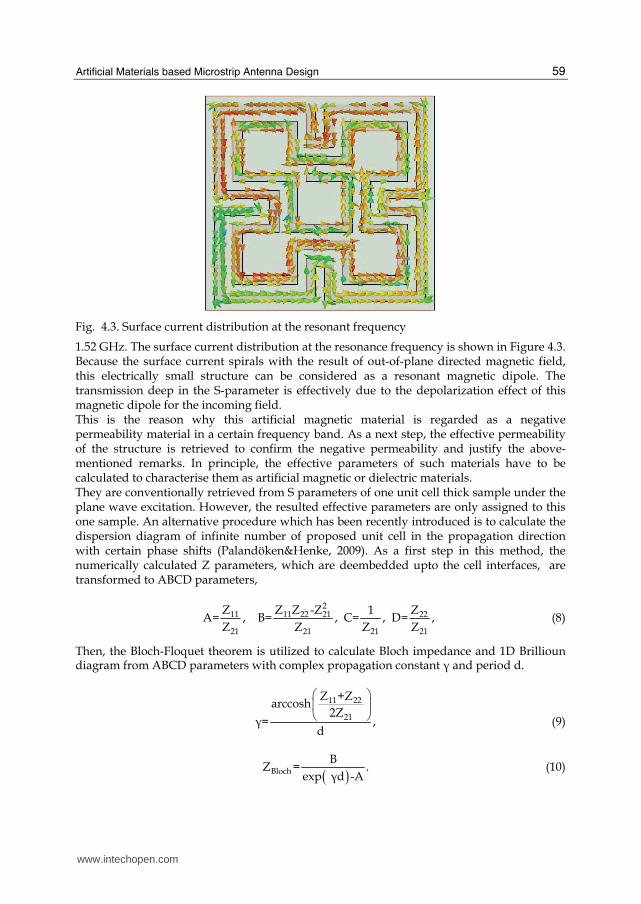
Fig. 4.3. Surface current distribution at the resonant frequency
1.52 GHz. The surface current distribution at the resonance frequency is shown in Figure 4.3. Because the surface current spirals with the result of out-of-plane directed magnetic field, this electrically small structure can be considered as a resonant magnetic dipole. The transmission deep in the S-parameter is effectively due to the depolarization effect of this magnetic dipole for the incoming field. This is the reason why this artificial magnetic material is regarded as a negative permeability material in a certain frequency band. As a next step, the effective permeability of the structure is retrieved to confirm the negative permeability and justify the above-mentioned remarks. In principle, the effective parameters of such materials have to be calculated to characterise them as artificial magnetic or dielectric materials. They are conventionally retrieved from S parameters of one unit cell thick sample under the plane wave excitation. However, the resulted effective parameters are only assigned to this one sample. An alternative procedure which has been recently introduced is to calculate the dispersion diagram of infinite number of proposed unit cell in the propagation direction with certain phase shifts (Palandöken&Henke, 2009). As a first step in this method, the numerically calculated Z parameters, which are deembedded upto the cell interfaces, are transformed to ABCD parameters,
2
11 11 22 21 22
21 21 21 21
Z Z Z -Z 1 ZA= , B= , C= , D= ,
Z Z Z Z (8)
Then, the Bloch-Floquet theorem is utilized to calculate Bloch impedance and 1D Brillioun diagram from ABCD parameters with complex propagation constant ┛ and period d.
11 22
21
Z +Zarccosh
2Z┛= ,
d
⎛ ⎞⎜ ⎟⎝ ⎠ (9)
( )Bloch
BZ = .
exp ┛d -A (10)
www.intechopen.com
Microstrip Antennas
60
The effective permeability can then be easily calculated from Bloch impedance and propagation constant with free space wave number ko, and line impedance Zo
Blocheff.
0 0
-j┛Z┤ = . k Z
(11)
The propagation constant and effective permeability are shown in Figure 4.4.
Fig. 4.4.a. Real (blue) and imaginary (red) part of complex propagation constant
Fig. 4.4.b. Real (red) and imaginary (blue) part of effective relative permeability
As it can be deduced from Figure 4.4.a, the exciting plane wave is exponentially attenuated in the frequency band of 1.45-1.96 GHz due to nonzero attenuation parameter. This results to have pure capacitive Bloch line impedance through the periodic unit cells. This reactive Bloch impedance could be modeled as series and shunt capacitances, which is the transmission line model of negative permeability metamaterials (Caloz & Itoh, 2005, Eleftheriades & Balmain, 2005). From Figure 4.4.b, the magnetic resonance frequency, 1.52 GHz, can be identified at which EBG, which is composed of periodically oriented fractal spiral resonators, can be operated as AMC due to high Bloch impedance and relative
www.intechopen.com
Artificial Materials based Microstrip Antenna Design
61
permeability. In addition, there is also a broader bandwidth of negative permeability, which is obtained between the magnetic resonance and plasma frequency at which surface wave propagation through the substrate could be suppressed. As a result, the proposed fractal spiral resonator, which is electrically small with the unit cell size of approximately 1/40 of resonant wavelength can be effectively utilized in artificial ground plane design. In the antenna design, the radiating element of either magnetic or electric dipole antenna is mostly located on the EBG surface with a substrate of certain distance inbetween. In addition, rather than artificially structuring the substrate and ground plane of microstrip antennas,which was explained in the previous sections, the radiating element itself can also be designed with electrically small self-resonating structures, which is explained in the next section.
5. Metamaterials based antenna design
As it was pointed out in the previous sections, metamaterial structures are able to sustain strong subwavelength resonances in the form of magnetic or electric dipole. These two types of dipoles can also be coupled in the same unit cell to excite both radiators in smaller size. In other words, the inductive impedance of negative permittivity material (ENG) can be compensated with the capacitive impedance of negative permeability material (MNG) as in double negative material (DNG). This leads these electrically small structures to be utilized as the resonators in miniturized antennas. Rather than designing self-resonating structures for new antenna topologies, there is a great deal of interest in enhancing the performance of conventional electrically small non-resonant antennas (ESA). As an attempt, the performance of ESAs surrounded by metamaterial shells was originally shown in papers (Ziolkowski et al.,2006; Ziolkowski et al.,2005; Ziolkowski et al.,2003; Li et al.,2001), in which significant gain enhancement of an electrically small dipole can be accomplished by surrounding it with a (DNG) shell. It is because high capacitive impedance of dipole is compensated with inherent inductance and capacitance of DNG, which results the resonance frequency to shift from the eigenfrequencies in the passband of DNG due to capacitive loading. In other words, the whole system comprised of electric dipole and DNG shell resonates rather than dipole itself. The gain is therefore higher due to not only matching of non-resonant dipole but also the contribution of metamaterial shell into the radiation as in the case of phased antenna arrays. A similar configuration for an infinitesimal dipole surrounded by an ENG shell in (Ziolkowski et al.,2007) was shown to demonstrate a very large power gain, due to the resonance between the inductive load offered by the ENG shell and the capacitive impedance of the dipole in the inner medium. A multilayer spherical configuration was presented in (Kim et al, 2007) to achieve gain enhancement for an electrically small antenna. And the radiated power gain of the DNG/MNG shell was also compared with respect to a loop antenna of the same radius as the outer radius of the shell and reasonably good power gains were obtained (Ghosh et al.,2008 ). In analogy with the electrically small dipole, the inductive impedance of electrically small loop antenna can be matched with the capacitive impedance of MNG shell. The resulting shell/magnetic loop system couples to DNG material effectively due to enhanced near field, resulting the whole system to resonate and cumulatively radiate in large volume. In this section, a metamaterial based antenna, which is composed of self-resonating slots
and an exciting small microstrip monopole, is explained. The electrically small monopole is
www.intechopen.com
Microstrip Antennas
62
coupled to the slot radiators capacitively to excite the compact resonators for subwavelength
operation. The radiating slots are located horizontally over the large ground plane while the
exciting microstrip monopole is located vertically on the ground plane and connected to the
inner conductor of SMA connector. The main radiating section of the antenna is composed
of four slotted array of the unit cell shown in Figure 3.1 in Section 3. In Section 5.1, the
geometrical model of the metamaterial inspired radiator is explained. In Section 5.2, the
antenna geometry is explained along with the design and operation principle. In Section 5.3,
the numerically calculated return loss and radiation patterns are presented.
5.1 Metamaterial inspired radiating structure
The main radiating section of the antenna is composed of four slots of the unit cell proposed
in (Palandöken et al. 2009). Because the electrical length of each resonator can be increased
by the direct connection with the neighboring resonator antisymmetrically, the radiator is
structured as shown in Figure 5.1. This perforated structure is located perpendicular to the
substrate of exciting monopole. The overall size is 14 mm x 6 mm. The separation distance
between each pair of resonators is 0.4 mm.
Fig. 5.1. Metamaterial slot radiator geometry
5.2 Antenna design
The metamaterial resonator based slot antenna is shown in Figure 5.2. In the antenna
model, the inner conductor of SMA is extended to be connected with the microstrip line of
monopole. The length of extended inner conductor from the ground plane surface is 2 mm.
The substrate material is 0.5 mm thick FR4 with the ground plane length Lgrn = 6mm. There
is a small gap between the slot resonators and microstrip line with the arm width, Wmat
=6.5mm and length Lmat=6mm, which enhances the impedance matching and capacitive
field coupling from the feeding line to the slots. The monopole feeding line is situated
exactly in the middle of the resonator in case two slot resonators are excited to be coupled
magnetically. The microstrip monopole has two main design advantages. Firstly, it is a
supporting material for the radiating slot resonator to be located on due to no substrate
under the radiator. Secondly, it results matching network to be designed on the feeding
monopole without increasing antenna size. The microstrip monopole with T-formed
matching section is shown in Figure 5.3.
www.intechopen.com
Artificial Materials based Microstrip Antenna Design
63
Lgrn
(a) (b)
Fig. 5.2. (a) Top and (b) side view of metamaterial based microstrip antenna
Wmat
Lmat
Fig. 5.3. Microstrip feeding monopole antenna
On the other hand, the spiral nature of SRs and linear form of the slotted thin wires in the
radiating section lead the excited virtual magnetic currents to react the structure as a
combination of electric and magnetic dipole, respectively. Therefore , the operation principle
of the antenna is based on the excitation of the horizontally oriented magnetic and vertically
oriented electric dipoles. Because these dipoles have the same direction directed image
currents due to perfect electric ground plane, this radiator topology results both dipole
types to radiate effectively.
www.intechopen.com
Microstrip Antennas
64
5.3 Simulation results
The return loss of metamaterial inspired antenna is numerically calculated with HFSS and
shown in Figure 5.4. The resonance frequency is 5.25 GHz. The resonance frequency is
higher than the eigenfrequencies in the passband of unit cell due to the slotted form and no
existence of substrate. This proposed topology increases the radiation efficiency and gain of
the antenna in comparison to the alternative design with substrate. The truncated ground of
microstrip monopole (Figure 5.2.b) increases the field coupling from the guided line to the
slot resonators, which results the antenna to be better impedance matched. On the other
hand, another advantage of the feeding line ground plane is to couple the incoming field
from the input port more effectively to the antenna without any leaking fields to the
surrounding large ground plane.
Fig. 5.4. Return loss of the metamaterial based slot antenna
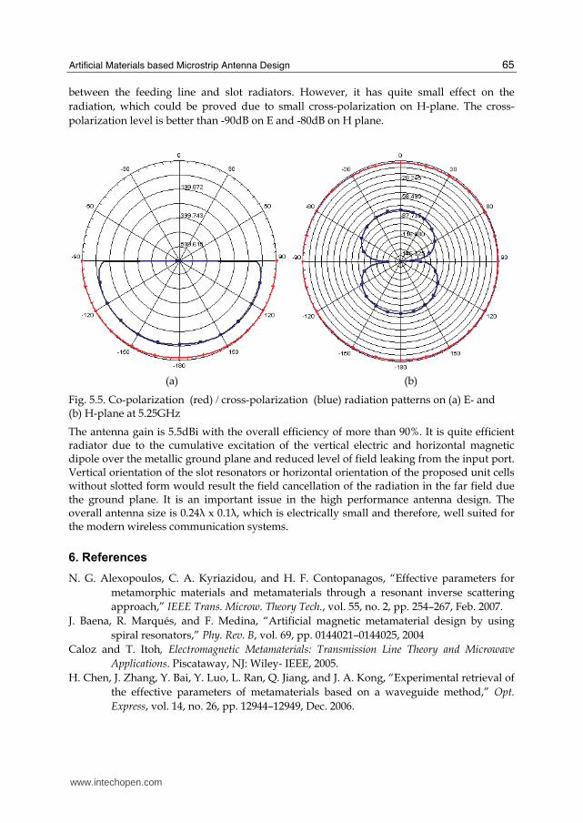
The normalized radiation patterns on H and E planes at 5.25 GHz are shown in Figure 5.5.
As deduced from Figure 5.5.b, the co-polarization radiation pattern on H plane has quite
similar form of H-plane radiation pattern of electric dipole. This is because of the excitation
of the spiral resonator with the eigencurrents in the form of virtual magnetic current.
Spiraling magnetic current generates the near field distribution as in the form of electric
dipole excitation due to Babinet's principle and duality. However, the radiation pattern on
E-plane is not similar to the dipole radiation because of the lack of radiation null on the
dipole axis. The reason of the enhanced radiation on the dipole axis is due to the
superposition of the dipole fields in four element dipole array on H plane and shift of the
antenna phase center. However, the radiation intensity along the dipole axis is minimum.
On the other hand, the cross-polarization radiation pattern on H plane is quite similar to the
radiation pattern of horizontally directed magnetic dipole. It is due to the excitation of
slotted connection lines of the spiral resonators in the slot radiator. There is another possible
magnetic radiation source, which originates from the electric coupling in the gap separation
www.intechopen.com
Artificial Materials based Microstrip Antenna Design
65
between the feeding line and slot radiators. However, it has quite small effect on the
radiation, which could be proved due to small cross-polarization on H-plane. The cross-
polarization level is better than -90dB on E and -80dB on H plane.
(a) (b)
Fig. 5.5. Co-polarization (red) / cross-polarization (blue) radiation patterns on (a) E- and (b) H-plane at 5.25GHz
The antenna gain is 5.5dBi with the overall efficiency of more than 90%. It is quite efficient radiator due to the cumulative excitation of the vertical electric and horizontal magnetic dipole over the metallic ground plane and reduced level of field leaking from the input port. Vertical orientation of the slot resonators or horizontal orientation of the proposed unit cells without slotted form would result the field cancellation of the radiation in the far field due the ground plane. It is an important issue in the high performance antenna design. The overall antenna size is 0.24┣ x 0.1┣, which is electrically small and therefore, well suited for the modern wireless communication systems.
6. References
N. G. Alexopoulos, C. A. Kyriazidou, and H. F. Contopanagos, “Effective parameters for
metamorphic materials and metamaterials through a resonant inverse scattering
approach,” IEEE Trans. Microw. Theory Tech., vol. 55, no. 2, pp. 254–267, Feb. 2007.
J. Baena, R. Marqués, and F. Medina, “Artificial magnetic metamaterial design by using
spiral resonators,” Phy. Rev. B, vol. 69, pp. 0144021–0144025, 2004
Caloz and T. Itoh, Electromagnetic Metamaterials: Transmission Line Theory and Microwave
Applications. Piscataway, NJ: Wiley- IEEE, 2005.
H. Chen, J. Zhang, Y. Bai, Y. Luo, L. Ran, Q. Jiang, and J. A. Kong, “Experimental retrieval of
the effective parameters of metamaterials based on a waveguide method,” Opt.
Express, vol. 14, no. 26, pp. 12944–12949, Dec. 2006.
www.intechopen.com
Microstrip Antennas
66
Chen, T. M. Grzegorczyk, B.-I.Wu, J. Pacheco, Jr., and J. A. Kong, “Robust method to retrieve
the constitutive effective parameters of metamaterials,” Phys. Rev. Lett. E, vol. 70,
pp. 0166081–0166087, 2004.
J. Chu, “Physical limitations on omnidirectional antennas,” J. Appl. Phys., vol. 19, pp. 1163–
1175, Dec. 1948
G. V. Eleftheriades and K. G. Balmain, Negative Refraction Metamaterials: Fundamental
Principles and Applications. New York:Wiley Interscience, 2005
N. Engheta and R. W. Ziolkowski, Metamaterials Physics and Engineering Explorations, , Eds.
New York: Wiley/IEEE, 2006.
W. Geyi, P. Jarmuszewski, and Y. Qi, “The Foster reactance theorem for antenna radiation
Q,” IEEE Trans. Antennas Propag., vol. 48, no. 3, pp. 401–408, Mar. 2000.
Geyi, W. , “Physical limitations of antenna,”, Antennas and Propagation, IEEE Transactions on
pp. 2116 - 2123 , Volume: 51 Issue: 8, Aug. 2003
Ghosh, B., S. Ghosh, and A. B. Kakade, “Investigation of gain enhancement of electrically
small antennas using double-negative, single-negative, and double-positive
materials,” Physical Review E, Vol. 78, 026611, 2008.
G. Goussetis, A.P. Feresidis, J.C. Vardaxoglou, Tailoring the AMC and EBG Characteristics
of Periodic Metallic Arrays Printed on Grounded Dielectric Substrate. IEEE
Transactions on Antennas and Propagation, vol. 54, no. 1, January 2006.
R. F. Harrington, "Effect of antenna size on gain, bandwidth, and efficiency", J. Res. Nat.
Bureau Stand., vol. 64D, pp. 1 - 12, 1960.
H. Iizuka and P. S. Hall, “Left-handed dipole antennas and their implementations,” IEEE
Trans. Antennas Propag., vol. 55, no. 5, pp. 1246–1253, May 2007
T. Jiang, Y. Yuan, D. Wang, L. Ran, and J. A. Kong, “High directive cavity antenna based on
1D LHM-RHM resonator,” in PIERS, 2007, vol. 3, no. 3, pp. 2054–2056.
R. C. Johnson, Antenna Engineering Handbook, 3rd ed. New York: McGraw-Hill.
Kim, H. Y., J. K. Kim, J. H. Kim, Y. J. Kim, and H. M. Lee, “Design of metamaterial structure
based electrically small monopole antenna,” 2007 Autumn Microwave & Radio
Wave Conference, Vol. 30, 577–580, September 2007
K. L. Lau, K. C. Kong, and K. M. Luk, “A miniature folded shorted patch antenna for dual-
band operation,” IEEE Trans. Antennas. Prop.,vol. 55, no.8, pp. 2391–2398, Aug. 2007
C.-J. Lee, K. M. K. H. Leong, and T. Itoh, “Composite right/left-handed transmission line
based compact resonant antennas for RF module integration,” IEEE Trans. Antennas
Propag., vol. 54, no. 8, pp. 2283–2291, Aug. 2006.
C.-J. Lee, K. M. K. H. Leong, and T. Itoh, “Design of resonant small antenna using composite
Sievenpiper, L. Zhang, R. Broas, N.G. Alexopolous, and E. Yablonovitch, High-
impedanceelectromagnetic surfaces with a forbidden frequency band, IEEE Trans
Microwave Theory Tech MTT-47 (1999), 2059–2074.
A. K. Skrivervik, J. -F. Zürcher, O. Staub, and J. R. Mosig, “PCS antenna design: The
challenge of miniaturization,” IEEE Antennas Propag. Mag., vol. 43, no. 4, pp. 12–27,
Aug. 2001.
R. Smith, D. C. Vier, T. Koschny, and C. M. Soukoulis, “Electromagnetic parameter retrieval
from inhomogeneous metamaterials,” Phys. Rev. E, vol. 71, pp. 0366171–03661711,
2005.
R. Smith, W. J. Padilla, D. C. Vier, S. C. Nemat-Nasser, and S. Schultz, “Composite medium
with simultaneously negative permeability and permittivity,” Phys. Rev. Lett., vol.
84, no. 18, pp. 4184–4187, 2000.
Veselago G., “The electrodynamics of substance with simultaneously negative values of ┝ and ┤” Sov. Phys.-Usp., vol. 10, no. 4, pp.509–514, Jan.–Feb. 1968.
InTech ChinaUnit 405, Office Block, Hotel Equatorial Shanghai No.65, Yan An Road (West), Shanghai, 200040, China
Phone: +86-21-62489820 Fax: +86-21-62489821
In the last 40 years, the microstrip antenna has been developed for many communication systems such asradars, sensors, wireless, satellite, broadcasting, ultra-wideband, radio frequency identifications (RFIDs),reader devices etc. The progress in modern wireless communication systems has dramatically increased thedemand for microstrip antennas. In this book some recent advances in microstrip antennas are presented.
How to referenceIn order to correctly reference this scholarly work, feel free to copy and paste the following:
Merih Palando ̈ken (2011). Artificial Materials based Microstrip Antenna Design, Microstrip Antennas, Prof.Nasimuddin Nasimuddin (Ed.), ISBN: 978-953-307-247-0, InTech, Available from:http://www.intechopen.com/books/microstrip-antennas/artificial-materials-based-microstrip-antenna-design