Artisan Technology Group is your source for quality new and certified-used/pre-owned equipment • FAST SHIPPING AND DELIVERY • TENS OF THOUSANDS OF IN-STOCK ITEMS • EQUIPMENT DEMOS • HUNDREDS OF MANUFACTURERS SUPPORTED • LEASING/MONTHLY RENTALS • ITAR CERTIFIED SECURE ASSET SOLUTIONS SERVICE CENTER REPAIRS Experienced engineers and technicians on staff at our full-service, in-house repair center WE BUY USED EQUIPMENT Sell your excess, underutilized, and idle used equipment We also offer credit for buy-backs and trade-ins www.artisantg.com/WeBuyEquipment REMOTE INSPECTION Remotely inspect equipment before purchasing with our interactive website at www.instraview.com LOOKING FOR MORE INFORMATION? Visit us on the web at www.artisantg.com for more information on price quotations, drivers, technical specifications, manuals, and documentation Contact us: (888) 88-SOURCE | [email protected]| www.artisantg.com SM View Instra
Transcript
Artisan Technology Group is your source for quality new and certified-used/pre-owned equipment
• FAST SHIPPING AND DELIVERY
• TENS OF THOUSANDS OF IN-STOCK ITEMS
• EQUIPMENT DEMOS
• HUNDREDS OF MANUFACTURERS SUPPORTED
• LEASING/MONTHLY RENTALS
• ITAR CERTIFIED SECURE ASSET SOLUTIONS
SERVICE CENTER REPAIRSExperienced engineers and technicians on staff at our full-service, in-house repair center
WE BUY USED EQUIPMENTSell your excess, underutilized, and idle used equipment We also offer credit for buy-backs and trade-inswww.artisantg.com/WeBuyEquipment
REMOTE INSPECTIONRemotely inspect equipment before purchasing with our interactive website at www.instraview.com
LOOKING FOR MORE INFORMATION? Visit us on the web at www.artisantg.com for more information on price quotations, drivers, technical specifications, manuals, and documentation
ALPHI TECHNOLOGY CORP. Page ii REV 2.2 Part Number : 722-1-000-4000 Copyright Alphi Technology Corporation ,1996 4/15/97
NOTICE
The information in this document has been carefully checked and is believed to be entirely reliable. While all reasonable efforts to ensure accuracy have been taken in the preparation of this manual, ALPHI TECHNOLOGY assumes no responsibility resulting from omissions or errors in this manual, or from the use of information contain herein. ALPHI TECHNOLOGY reserves the right to make any changes, without notice, to this or any of ALPHI TECHNOLOGY’s products to improve reliability, performance, function or design. ALPHI TECHNOLOGY does not assume any liability arising out of the application or use of any product or circuit described herein; nor does ALPHI TECHNOLOGY convey any license under its patent rights or the rights of others.
ALPHI TECHNOLOGY CORPORATION All Rights Reserved
This document shall not be duplicated, nor its contents used for any purpose, unless express permission has been granted in advance.
ALPHI TECHNOLOGY CORP. Page 1 REV 2.2 Part Number : 722-1-000-4000 Copyright Alphi Technology Corporation ,1996 4/15/97
1. GENERAL DESCRIPTION ULTRA LOW POWER 68030 The ICC8, is a intelligent communication controller based on a 68030 processor board with 8 RS232/422/485 serial ports. This product is optimized for applications requiring a high performance general purpose CPU with low power consumption or dissipation. Exclusive use of CMOS components guaranties not only low overall power use but also the absence of “hot-points”. This allows the ICC8 module to be put in an airtight box that will fit the most trying environment; therefore protecting against dust or other contaminants. The resources already available on the board will fit most applications. However, if additional resources are needed, the board standard VME interface allows the user to tap the wealth of available VMEbus modules to complete the system.
* Up to 4 Mbyte of SRAM with battery back up * Up to 8 Mbytes of EPROM (4 sockets) * 8 RS232/RS485 serial interface with Z85C30 SCC * Supports async and synchronous bit and character oriented protocols * Two 8 bit parallel interfaces with handshake lines (P2 connector) * Two independent 16-bit counter/timers with access lines on P2 connector * Time-of-day clock with battery backup * Independent watchdog timer * Fully VMEbus Rev C compatible * Single level VMEbus arbiter * Sysclk driver * Supports ACFAIL* and SYSFAIL* interrupts * CMOS for low power
ALPHI TECHNOLOGY CORP. Page 2 REV 2.2 Part Number : 722-1-000-4000 Copyright Alphi Technology Corporation ,1996 4/15/97
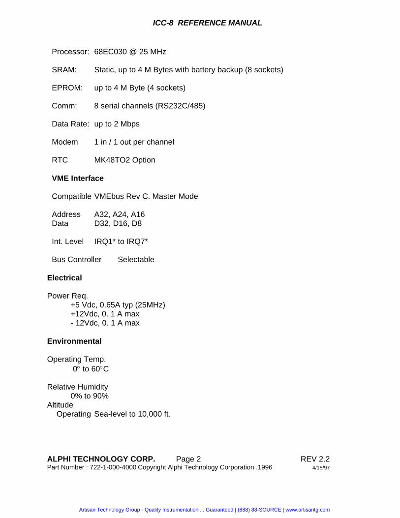
Processor: 68EC030 @ 25 MHz SRAM: Static, up to 4 M Bytes with battery backup (8 sockets) EPROM: up to 4 M Byte (4 sockets) Comm: 8 serial channels (RS232C/485) Data Rate: up to 2 Mbps Modem 1 in / 1 out per channel RTC MK48TO2 Option VME Interface Compatible VMEbus Rev C. Master Mode Address A32, A24, A16 Data D32, D16, D8 Int. Level IRQ1* to IRQ7* Bus Controller Selectable Electrical Power Req. +5 Vdc, 0.65A typ (25MHz) +12Vdc, 0. 1 A max - 12Vdc, 0. 1 A max Environmental Operating Temp. 0° to 60°C Relative Humidity 0% to 90% Altitude Operating Sea-level to 10,000 ft.
ALPHI TECHNOLOGY CORP. Page 3 REV 2.2 Part Number : 722-1-000-4000 Copyright Alphi Technology Corporation ,1996 4/15/97
2. FUNCTIONAL DESCRIPTION
2.1 MEMORY
2.1.1 RAM The ICC8 module has 8 x 32-pin JEDEC sockets that can receive either 128Kx8, OR 512KX8 static RAM chips. The ICC8 memory is backed by a lithium battery. Using low-power memories (1pA typical), the battery will be able to maintain the data for 5 years (typical) in the absence of any external source of power. Disconnecting the jumper W08 will stop the battery backup and will prevent the battery from discharging. Thus, allowing for a longer storage period. The reset circuitry automatically disables the memory chip select if the VCC voltage drops below 4.5V. This mechanism protects the memory content in case of a power failure.
2.1.2 EPROM The ICC8 module has 4 x 32 Pin sockets allowing up to 2 Mbytes of EPROM. EPROMs supported range from the 8Kx8 2764 to the 512Kx8. The jumper area W7 selects the type of EPROM. Table 2.1 shows the different EPROMs supported and the corresponding jumper configuration.
ALPHI TECHNOLOGY CORP. Page 4 REV 2.2 Part Number : 722-1-000-4000 Copyright Alphi Technology Corporation ,1996 4/15/97
Eight serial channels are installed on the ICC8. All eight channels are controlled by four Zilog Z85C30 Serial Communication Controllers (SCC). The SCC supports many synchronous and asynchronous protocols. All eight ports are accessible on the front panel.
2.3.1 SCC Description The board uses four on board Z85C30s as serial interfaces. This controller can be configured by software to satisfy a wide variety of serial communication applications. The Z85C30 contains a variety of sophisticated internal functions including on-chip baud rate generators, digital phase-locked loops, and crystal oscillators. It handles asynchronous formats and synchronous byte-oriented protocols such as HDLC and SDLC. It can generate and check CRC codes in any synchronous mode and can be programmed to check data integrity in various modes. The clock signal PCLK is generated by a 7.372 MHz crystal oscillator.
Address Register $F30201C3 Channel H Command Register $F30201C7 Channel H Data Register $F30201CB Channel G Command Register $F30201CF Channel G Data Register $F3020183 Channel F Command Register $F3020187 Channel F Data Register $F302018B Channel E Command Register $F302018F Channel E Data Register $F3020143 Channel D Command Register $F3020147 Channel D Data Register $F302014B Channel C Command Register $F302014F Channel C Data Register $F3020103 Channel B Command Register $F3020107 Channel B Data Register $F302010B Channel A Command Register $F302010F Channel A Data Register
ALPHI TECHNOLOGY CORP. Page 8 REV 2.2 Part Number : 722-1-000-4000 Copyright Alphi Technology Corporation ,1996 4/15/97
2.6 PARALLEL INTERFACE AND TIMER
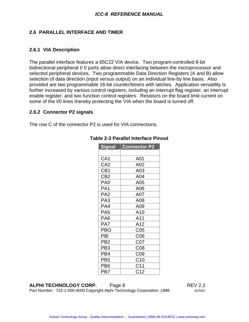
2.6.1 VIA Description The parallel interface features a 65C22 VIA device. Two program-controlled 8-bit bidirectional peripheral I/ 0 ports allow direct interfacing between the microprocessor and selected peripheral devices. Two programmable Data Direction Registers (A and B) allow selection of data direction (input versus output) on an individual line-by line basis. Also provided are two programmable 16-bit counter/timers with latches. Application versatility is further increased by various control registers, including an interrupt flag register, an interrupt enable register, and two function control registers. Resistors on the board limit current on some of the I/0 lines thereby protecting the VIA when the board is turned off.
2.6.2 Connector P2 signals The row C of the connector P2 is used for VIA connections.
ALPHI TECHNOLOGY CORP. Page 9 REV 2.2 Part Number : 722-1-000-4000 Copyright Alphi Technology Corporation ,1996 4/15/97
2.7 REAL-TIME CLOCK The on-board real-time clock uses a Mostek chip MM5827c.
Address Function $F301000 CONTROL REG. $F301001 TENTHS OF SEC. $F301002 SECONDS $F301003 TENS OF SECONDS $F301004 MINUTES $F301005 TENS OF MINUTES $F301006 HOURS $F301007 TENS OF HOURS $F301008 DAYS $F301009 TENS OF DAYS $F30100A MONTHS $F30100B TENS OF MONTH $F30100C YEARS $F30100D TENS OF YEARS $F30100E DAY OF WEEK $F30100F CLOCK SETTING INTERRUPT
ALPHI TECHNOLOGY CORP. Page 11 REV 2.2 Part Number : 722-1-000-4000 Copyright Alphi Technology Corporation ,1996 4/15/97
2.9 RESET AND WATCHDOG The ICC8 module reset and watchdog cicuit has been designed to guarantee the board reliable function in a variety of conditions. When power is off, the module resets the CPU as soon as the power voltage drops below 4.5V. This operation also prevents accidental corruption of the data in the battery backup RAM. The optional real-time clock has its own circuitry protecting it on power-down. On power-on or when the user activates the front panel reset push-button, the reset circuitry asserts the internal RESET* signal for a minimum of 200 mS after VCC has risen above 4.75V.
ALPHI TECHNOLOGY CORP. Page 12 REV 2.2 Part Number : 722-1-000-4000 Copyright Alphi Technology Corporation ,1996 4/15/97
2.10 ADDRESS MAP On reset, the bit CR5 of the control register is set to 0, selecting the alternate address map. This allows the 68030 to fetch the reset vectors in the EPROM. This bit should be set to 1 by the initialization routine to allow RAM accesses at the address 0. On request, Alphi can provide the user with the information to customize the address map if necessary. The following tables show the different address map depending on the decoding PAL and the value of the bit CR5 of the control register.
Table 2.7: Standard Address Map
Address Function $00000000-$00FFFFFF Local RAM $01000000-$7FFFFFFF VME A32/D32 $80000000-$EFFFFFFF VME A32/D16 $F0000000-$F0FFFFFF VME A24/D16 $F1000000-$F100FFFF VME A16/D16 $F3000000-$F300FFFF 6522 VIA $F301000-$F301FFFF RTC $F3020040 Control Register $F3020050 Output port C $F3020103-$f302013F Serial Controller 1 $F3020143-$F302017F Serial Controller 2 $F3020183-$F30201BF Serial Controller 3 $F30201C3-$F30201FF Serial Controller 4 $FE000000-$FEFFFFFF Local Prom $FF000000-$FFFFFFFF VME A24/D32
Table 2.8: Alternate Address Map
Address Function $00000000-$00FFFFFF Local PROM $F4000000-$F4FFFFFF Local RAM
ALPHI TECHNOLOGY CORP. Page 13 REV 2.2 Part Number : 722-1-000-4000 Copyright Alphi Technology Corporation ,1996 4/15/97
Table 2.9: Internal Interrupt levels
Interupt Source Level7 VMEbus ACFAIL* Level7 Abort Push-button Level 6 Serial Controller IRQ Level 5 Serial Controller IRQ Level 4 Serial Controller IRQ Level 3 VIA auto vector Level 2 SYSFAIL* auto vector Level 1 RTC auto vector
Internal Interrupt levels for the SCC
Serial Controller Group Jumper W9 Interrupt 1,2 1-2 IRQ6 3-4 IRQ5 5-6 IRQ4 3,4 7-8 IRQ6 9-10 IRQ5 11-12 IRQ4
2.11 CONTROL REGISTER The ICC8 Control register contains 8 bits which monitor and controls several of the board functions. Table 2.11 contains the meaning of the different bits. The Control register is accessible at the address $F3020040. The Status Register reflect most of the Bit of the Control Register. See Table below for details On board reset, all the bits of the control register are cleared.
Bit Name Description D7 DD31 D6 DD30 D5 DD29 CR5 = 0 alternate address map CR5 = 1 standard address map D4 DD28 WD Watchdog toggle bit D3 DD27
ALPHI TECHNOLOGY CORP. Page 15 REV 2.2 Part Number : 722-1-000-4000 Copyright Alphi Technology Corporation ,1996 4/15/97
2.13.2 STATUS Indicator This red LED reflects the state of the local processor STATUS line. When it is bright red, it means that the processor is halted (generally the result of a double bus fault).
3. HARDWARE PREPARATION
3.1 INTRODUCTION This chapter provides hardware preparation instructions for the ICC8 processor module.
ALPHI TECHNOLOGY CORP. Page 16 REV 2.2 Part Number : 722-1-000-4000 Copyright Alphi Technology Corporation ,1996 4/15/97
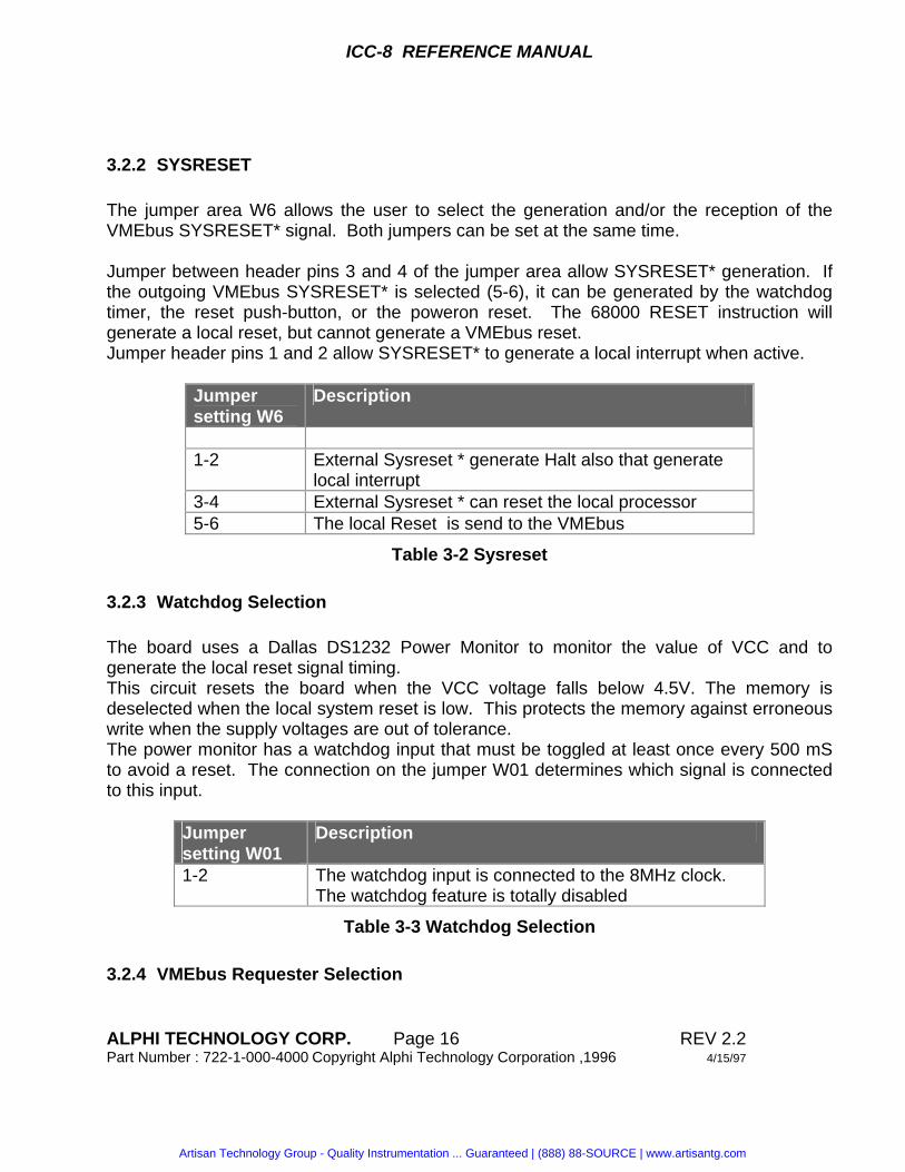
3.2.2 SYSRESET The jumper area W6 allows the user to select the generation and/or the reception of the VMEbus SYSRESET* signal. Both jumpers can be set at the same time. Jumper between header pins 3 and 4 of the jumper area allow SYSRESET* generation. If the outgoing VMEbus SYSRESET* is selected (5-6), it can be generated by the watchdog timer, the reset push-button, or the poweron reset. The 68000 RESET instruction will generate a local reset, but cannot generate a VMEbus reset. Jumper header pins 1 and 2 allow SYSRESET* to generate a local interrupt when active.
Jumper setting W6
Description
1-2 External Sysreset * generate Halt also that generate
local interrupt 3-4 External Sysreset * can reset the local processor 5-6 The local Reset is send to the VMEbus
Table 3-2 Sysreset
3.2.3 Watchdog Selection The board uses a Dallas DS1232 Power Monitor to monitor the value of VCC and to generate the local reset signal timing. This circuit resets the board when the VCC voltage falls below 4.5V. The memory is deselected when the local system reset is low. This protects the memory against erroneous write when the supply voltages are out of tolerance. The power monitor has a watchdog input that must be toggled at least once every 500 mS to avoid a reset. The connection on the jumper W01 determines which signal is connected to this input.
Jumper setting W01
Description
1-2 The watchdog input is connected to the 8MHz clock. The watchdog feature is totally disabled
ALPHI TECHNOLOGY CORP. Page 17 REV 2.2 Part Number : 722-1-000-4000 Copyright Alphi Technology Corporation ,1996 4/15/97
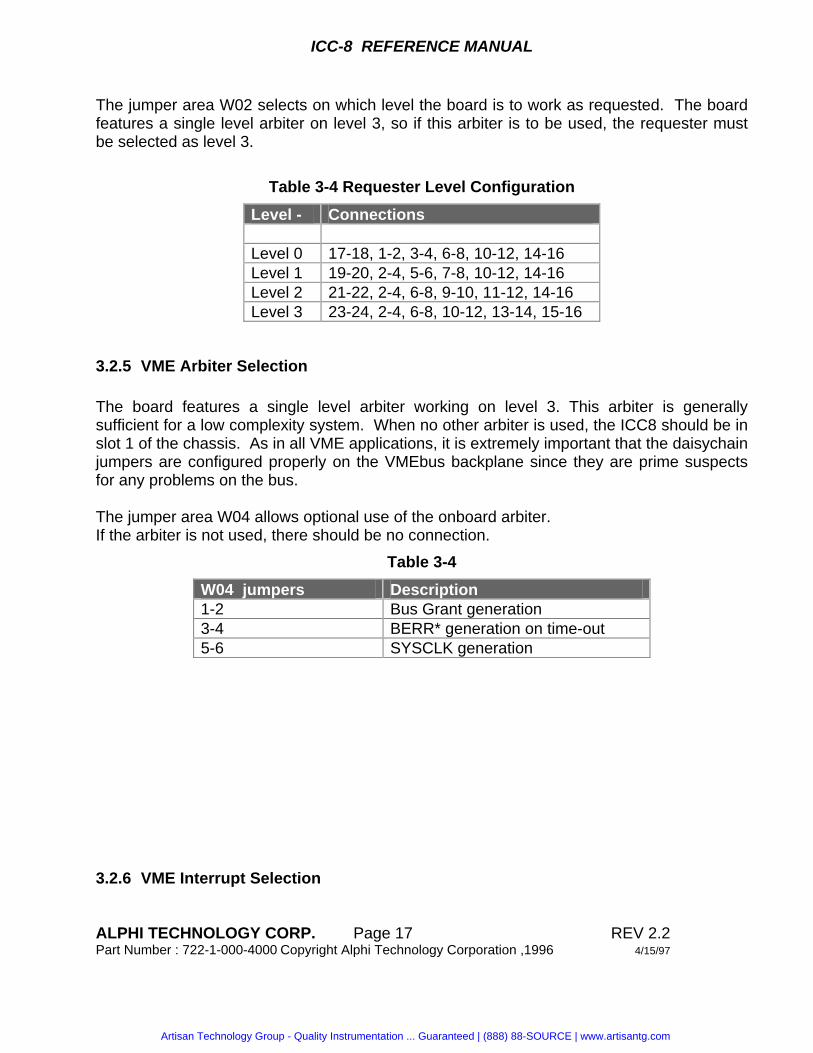
The jumper area W02 selects on which level the board is to work as requested. The board features a single level arbiter on level 3, so if this arbiter is to be used, the requester must be selected as level 3.
3.2.5 VME Arbiter Selection The board features a single level arbiter working on level 3. This arbiter is generally sufficient for a low complexity system. When no other arbiter is used, the ICC8 should be in slot 1 of the chassis. As in all VME applications, it is extremely important that the daisychain jumpers are configured properly on the VMEbus backplane since they are prime suspects for any problems on the bus. The jumper area W04 allows optional use of the onboard arbiter. If the arbiter is not used, there should be no connection.
Table 3-4
W04 jumpers Description 1-2 Bus Grant generation 3-4 BERR* generation on time-out 5-6 SYSCLK generation
ALPHI TECHNOLOGY CORP. Page 18 REV 2.2 Part Number : 722-1-000-4000 Copyright Alphi Technology Corporation ,1996 4/15/97
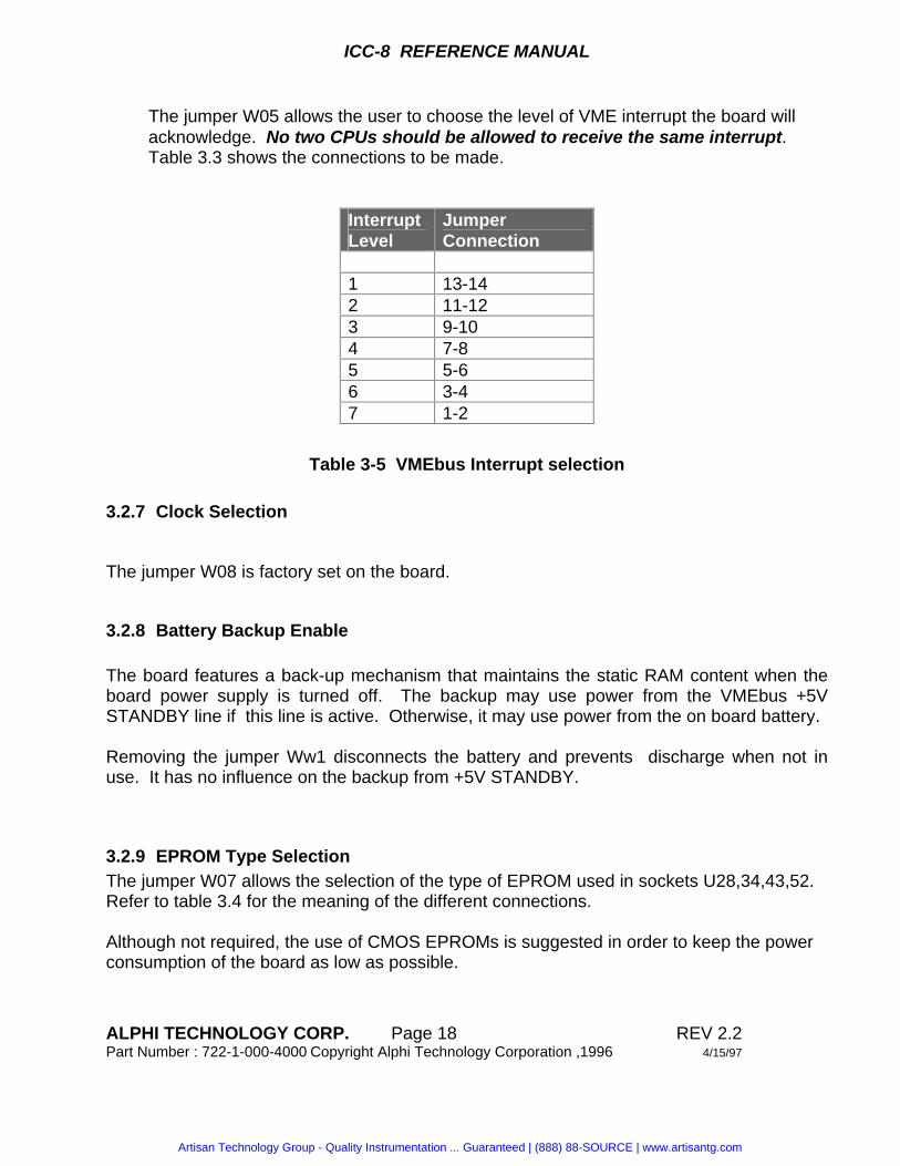
The jumper W05 allows the user to choose the level of VME interrupt the board will acknowledge. No two CPUs should be allowed to receive the same interrupt. Table 3.3 shows the connections to be made.
Interrupt Level
Jumper Connection
1 13-14 2 11-12 3 9-10 4 7-8 5 5-6 6 3-4 7 1-2
Table 3-5 VMEbus Interrupt selection
3.2.7 Clock Selection
The jumper W08 is factory set on the board.
3.2.8 Battery Backup Enable The board features a back-up mechanism that maintains the static RAM content when the board power supply is turned off. The backup may use power from the VMEbus +5V STANDBY line if this line is active. Otherwise, it may use power from the on board battery. Removing the jumper Ww1 disconnects the battery and prevents discharge when not in use. It has no influence on the backup from +5V STANDBY.
3.2.9 EPROM Type Selection The jumper W07 allows the selection of the type of EPROM used in sockets U28,34,43,52. Refer to table 3.4 for the meaning of the different connections. Although not required, the use of CMOS EPROMs is suggested in order to keep the power consumption of the board as low as possible.
3.2.10 Software Selection Jumpers Two read-only bits of the Status register allows the user software to verify the presence of connections on this jumper area. When the connection is done, the corresponding bit in the Status register reads 0. This can be used to indicate a hardware configuration or a start-up option, for instance.
Table 3.5: Software Option Bits
Connection Bit of the control register W10 1-2 6 3-4 5
Artisan Technology Group is your source for quality new and certified-used/pre-owned equipment
• FAST SHIPPING AND DELIVERY
• TENS OF THOUSANDS OF IN-STOCK ITEMS
• EQUIPMENT DEMOS
• HUNDREDS OF MANUFACTURERS SUPPORTED
• LEASING/MONTHLY RENTALS
• ITAR CERTIFIED SECURE ASSET SOLUTIONS
SERVICE CENTER REPAIRSExperienced engineers and technicians on staff at our full-service, in-house repair center
WE BUY USED EQUIPMENTSell your excess, underutilized, and idle used equipment We also offer credit for buy-backs and trade-inswww.artisantg.com/WeBuyEquipment
REMOTE INSPECTIONRemotely inspect equipment before purchasing with our interactive website at www.instraview.com
LOOKING FOR MORE INFORMATION? Visit us on the web at www.artisantg.com for more information on price quotations, drivers, technical specifications, manuals, and documentation