Page 1
8/3/2019 As CT2 - Waves, Electricity and Quantum - JAN 2012
http://slidepdf.com/reader/full/as-ct2-waves-electricity-and-quantum-jan-2012 1/13
WORDBRIDGE – WAVES, ELECTRICITY & QUANTUM (AS) CT:
SHK Page 1
1. (a) Explain why the resistance of a metallic conductor increases when its temperature is increased.
....................................................................................................................................................................
....................................................................................................................................................................
....................................................................................................................................................................
................................................................................................................................................................ (2)
(b) A lamp filament of length 0.17 m is made from tungsten. The radius of the filament is 2.1 × 10⁻⁵
m
and its resistance is 6.0 Ω. Calculate the resistivity of tungsten.
....................................................................................................................................................................
....................................................................................................................................................................
....................................................................................................................................................................
................................................................................................................................................................ (3)
2. Figures 2 shows a circuit in which there is a current in a metallic resistor, R, and in a salt solution, S.
Figure 2
The dots in R and S indicate the charge carriers in those materials.
(i) Label on Figure 2 the names and charges of each charge carrier.
(ii) Draw arrows on Figure 2 to show the directions of drift of the charge carriers shown. (5)
3. (a) (i) Describe what is meant by a superconductor.
....................................................................................................................................................................
....................................................................................................................................................................
....................................................................................................................................................................
................................................................................................................................................................ (1)
Page 2
8/3/2019 As CT2 - Waves, Electricity and Quantum - JAN 2012
http://slidepdf.com/reader/full/as-ct2-waves-electricity-and-quantum-jan-2012 2/13
WORDBRIDGE – WAVES, ELECTRICITY & QUANTUM (AS) CT:
SHK Page 2
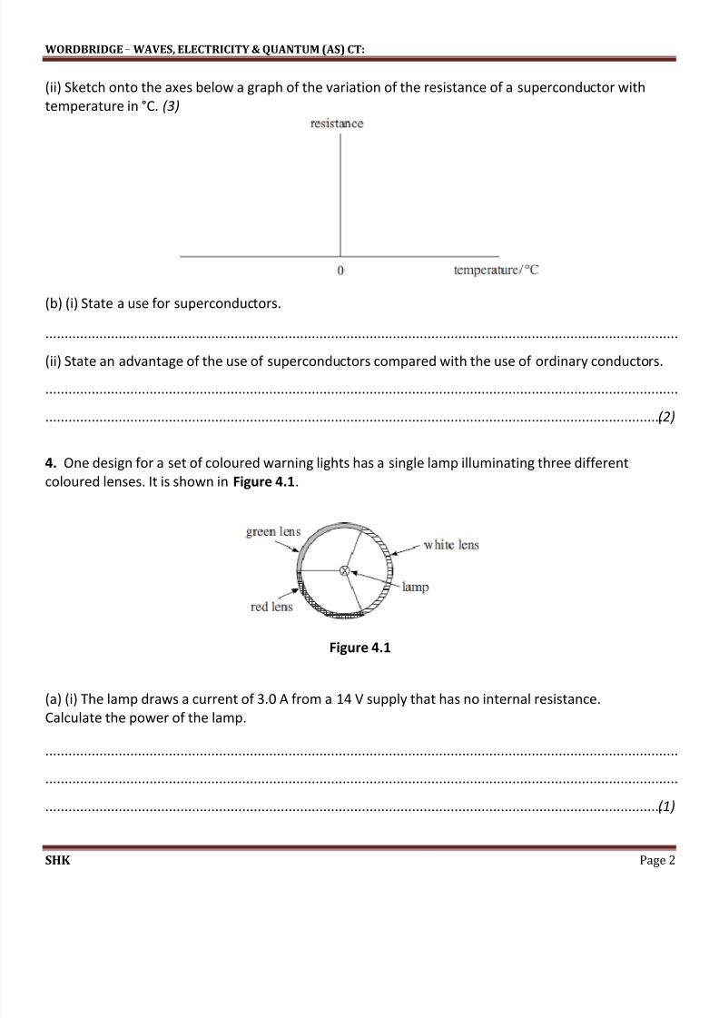
(ii) Sketch onto the axes below a graph of the variation of the resistance of a superconductor with
temperature in °C. (3)
(b) (i) State a use for superconductors.
....................................................................................................................................................................
(ii) State an advantage of the use of superconductors compared with the use of ordinary conductors.
....................................................................................................................................................................
................................................................................................................................................................ (2)
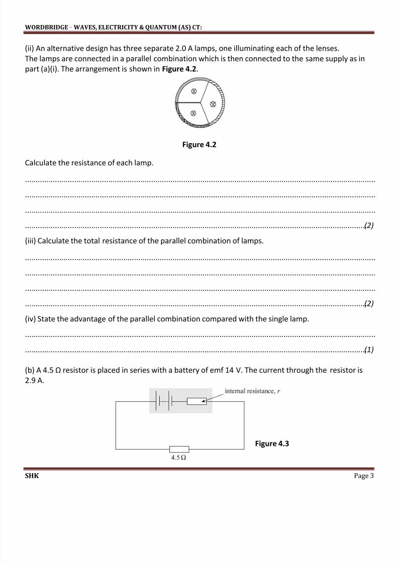
4. One design for a set of coloured warning lights has a single lamp illuminating three different
coloured lenses. It is shown in Figure 4.1.
Figure 4.1
(a) (i) The lamp draws a current of 3.0 A from a 14 V supply that has no internal resistance.
Calculate the power of the lamp.
....................................................................................................................................................................
....................................................................................................................................................................
................................................................................................................................................................ (1)
Page 3
8/3/2019 As CT2 - Waves, Electricity and Quantum - JAN 2012
http://slidepdf.com/reader/full/as-ct2-waves-electricity-and-quantum-jan-2012 3/13
WORDBRIDGE – WAVES, ELECTRICITY & QUANTUM (AS) CT:
SHK Page 3
(ii) An alternative design has three separate 2.0 A lamps, one illuminating each of the lenses.
The lamps are connected in a parallel combination which is then connected to the same supply as in
part (a)(i). The arrangement is shown in Figure 4.2.
Figure 4.2
Calculate the resistance of each lamp.
....................................................................................................................................................................
....................................................................................................................................................................
....................................................................................................................................................................
................................................................................................................................................................ (2)
(iii) Calculate the total resistance of the parallel combination of lamps.
....................................................................................................................................................................
....................................................................................................................................................................
....................................................................................................................................................................
................................................................................................................................................................ (2)
(iv) State the advantage of the parallel combination compared with the single lamp.
....................................................................................................................................................................
................................................................................................................................................................ (1)
(b) A 4.5 Ω resistor is placed in series with a battery of emf 14 V. The current through the resistor is
2.9 A.
Figure 4.3
Page 4
8/3/2019 As CT2 - Waves, Electricity and Quantum - JAN 2012
http://slidepdf.com/reader/full/as-ct2-waves-electricity-and-quantum-jan-2012 4/13
WORDBRIDGE – WAVES, ELECTRICITY & QUANTUM (AS) CT:
SHK Page 4
(i) Calculate the internal resistance, r , of the battery.
....................................................................................................................................................................
....................................................................................................................................................................
................................................................................................................................................................ (2)
(ii) Calculate the voltage lost across the internal resistance.
....................................................................................................................................................................
....................................................................................................................................................................
................................................................................................................................................................ (1)
5. Figure 5 shows the mode of vibration for a stretched string of length 0.45 m when it is emitting a
note of frequency 900 Hz.
Figure 5
(a) (i) How many nodes are there in the waveform?
................................................................................................................................................................ (1)
(ii) State the wavelength of the waves shown in Figure 5.
................................................................................................................................................................ (1)
(b) (i) Calculate the speed of waves along the string.
....................................................................................................................................................................
................................................................................................................................................................ (1)
(ii) The maximum frequency of vibration of this string that can be heard by an observer is 3600 Hz.
How many loops would occur when the string is emitting this frequency?
....................................................................................................................................................................
................................................................................................................................................................ (2)
Page 5
8/3/2019 As CT2 - Waves, Electricity and Quantum - JAN 2012
http://slidepdf.com/reader/full/as-ct2-waves-electricity-and-quantum-jan-2012 5/13
WORDBRIDGE – WAVES, ELECTRICITY & QUANTUM (AS) CT:
SHK Page 5
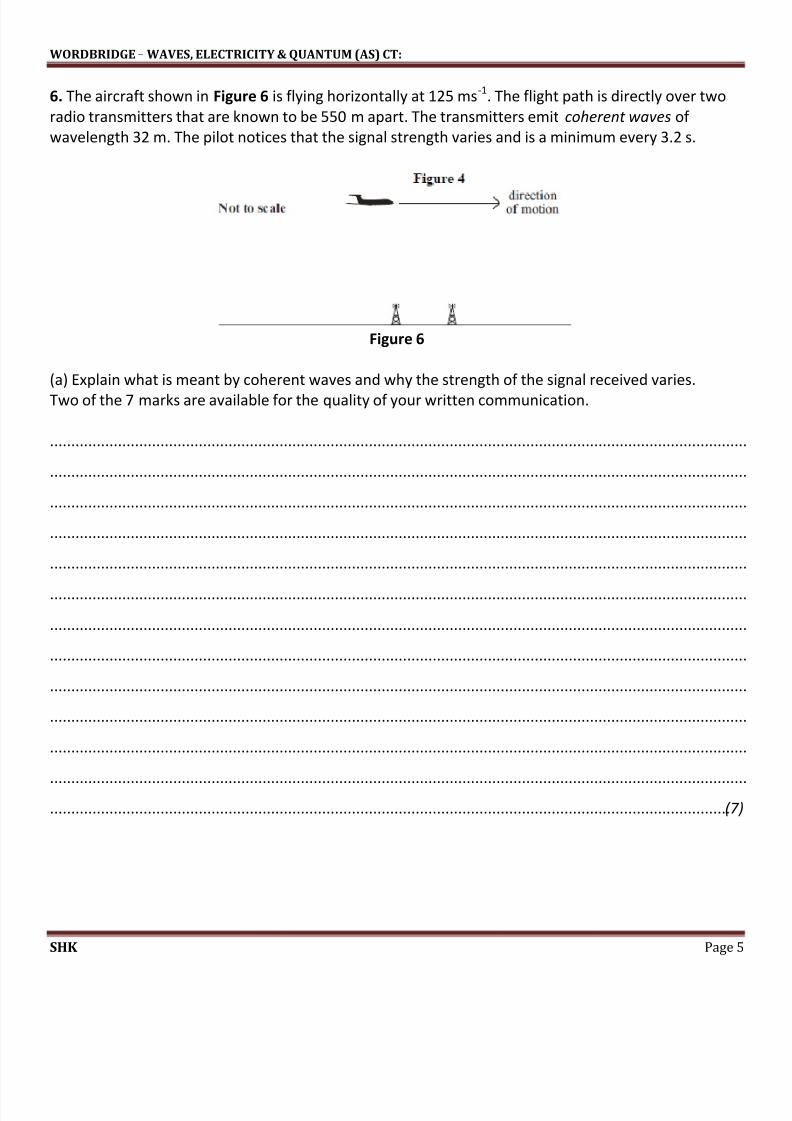
6. The aircraft shown in Figure 6 is flying horizontally at 125 ms-1
. The flight path is directly over two
radio transmitters that are known to be 550 m apart. The transmitters emit coherent waves of
wavelength 32 m. The pilot notices that the signal strength varies and is a minimum every 3.2 s.
Figure 6
(a) Explain what is meant by coherent waves and why the strength of the signal received varies.
Two of the 7 marks are available for the quality of your written communication.
....................................................................................................................................................................
....................................................................................................................................................................
....................................................................................................................................................................
....................................................................................................................................................................
....................................................................................................................................................................
....................................................................................................................................................................
....................................................................................................................................................................
....................................................................................................................................................................
....................................................................................................................................................................
....................................................................................................................................................................
....................................................................................................................................................................
....................................................................................................................................................................
................................................................................................................................................................ (7)
Page 6
8/3/2019 As CT2 - Waves, Electricity and Quantum - JAN 2012
http://slidepdf.com/reader/full/as-ct2-waves-electricity-and-quantum-jan-2012 6/13
WORDBRIDGE – WAVES, ELECTRICITY & QUANTUM (AS) CT:
SHK Page 6
(b) (i) Calculate the distance travelled by the aircraft between one position of minimum signal
strength and the next.
....................................................................................................................................................................
....................................................................................................................................................................
................................................................................................................................................................ (2)
(ii) Calculate the height at which the aircraft is flying.
....................................................................................................................................................................
....................................................................................................................................................................
................................................................................................................................................................ (2)
7. When electromagnetic radiation passes through hydrogen gas, some of the frequencies of the
radiation are absorbed. Figure 7.1 shows part of the absorption spectrum with a pronounced
absorption shown at point A.
Figure 7.1
(a) Show that an absorbed photon with a frequency corresponding to point A on the graph has an
energy of about 3 × 10-19
J.
Planck constant = 6.6 × 10⁻³⁴
J s
....................................................................................................................................................................
....................................................................................................................................................................
....................................................................................................................................................................
................................................................................................................................................................ (2)
Page 7
8/3/2019 As CT2 - Waves, Electricity and Quantum - JAN 2012
http://slidepdf.com/reader/full/as-ct2-waves-electricity-and-quantum-jan-2012 7/13
WORDBRIDGE – WAVES, ELECTRICITY & QUANTUM (AS) CT:
SHK Page 7
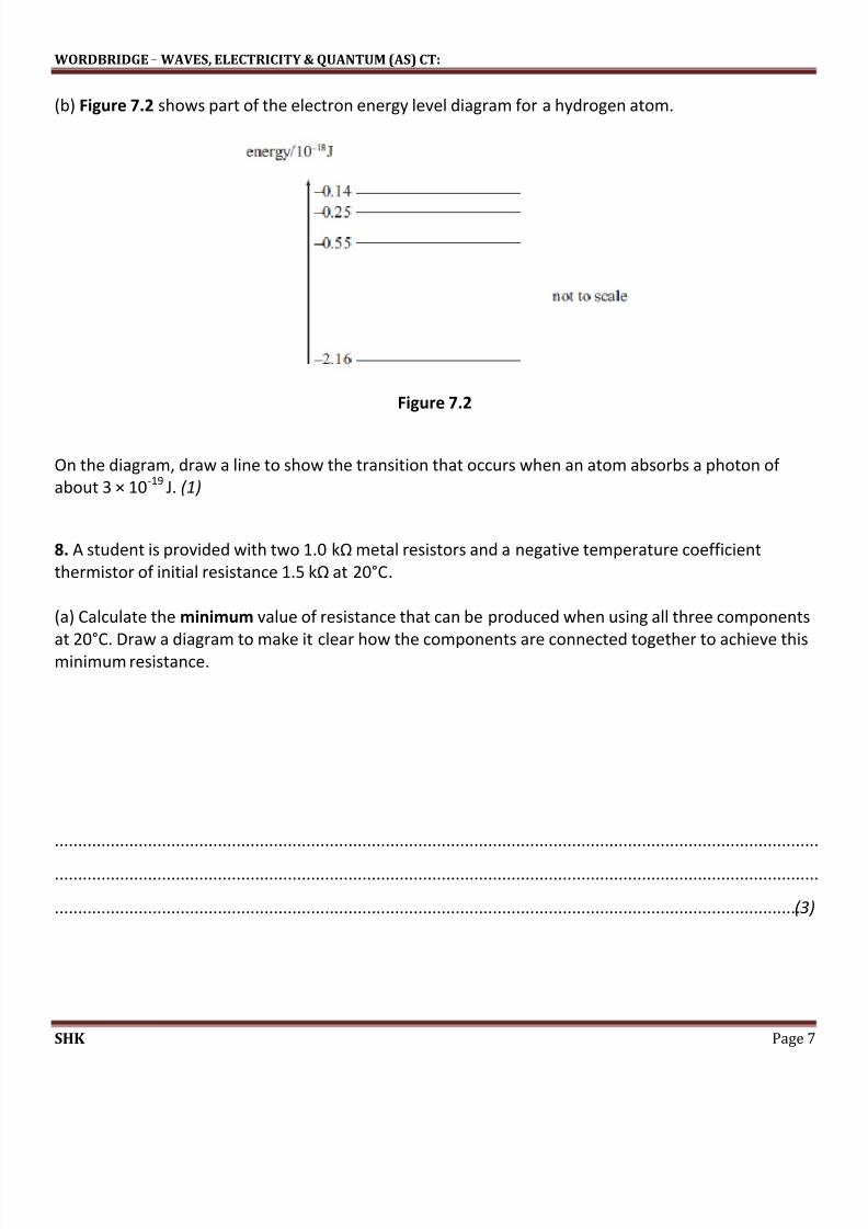
(b) Figure 7.2 shows part of the electron energy level diagram for a hydrogen atom.
Figure 7.2
On the diagram, draw a line to show the transition that occurs when an atom absorbs a photon of
about 3 × 10-19
J. (1)
8. A student is provided with two 1.0 kΩ metal resistors and a negative temperature coefficient
thermistor of initial resistance 1.5 kΩ at 20°C.
(a) Calculate the minimum value of resistance that can be produced when using all three components
at 20°C. Draw a diagram to make it clear how the components are connected together to achieve thisminimum resistance.
....................................................................................................................................................................
....................................................................................................................................................................
................................................................................................................................................................ (3)
Page 8
8/3/2019 As CT2 - Waves, Electricity and Quantum - JAN 2012
http://slidepdf.com/reader/full/as-ct2-waves-electricity-and-quantum-jan-2012 8/13
WORDBRIDGE – WAVES, ELECTRICITY & QUANTUM (AS) CT:
SHK Page 8
(b) When charge flows through the resistor network, the temperature of each component rises.
State and explain the changes in resistance that occur in each of the components as a result of the
changes in temperature.
....................................................................................................................................................................
....................................................................................................................................................................
....................................................................................................................................................................
....................................................................................................................................................................
....................................................................................................................................................................
....................................................................................................................................................................
....................................................................................................................................................................
....................................................................................................................................................................
....................................................................................................................................................................
....................................................................................................................................................................
....................................................................................................................................................................
................................................................................................................................................................ (3)
9. (a) Describe the difference between longitudinal and transverse waves.
....................................................................................................................................................................
....................................................................................................................................................................
....................................................................................................................................................................
................................................................................................................................................................ (2)
(b) (i) Light from a lamp is unpolarised. Explain how this light is different from light that has been
passed through a polarising filter.
....................................................................................................................................................................
....................................................................................................................................................................
................................................................................................................................................................ (1)
(ii) Name an example of a wave that cannot be polarised and explain why.
....................................................................................................................................................................
................................................................................................................................................................ (2)
Page 9
8/3/2019 As CT2 - Waves, Electricity and Quantum - JAN 2012
http://slidepdf.com/reader/full/as-ct2-waves-electricity-and-quantum-jan-2012 9/13
WORDBRIDGE – WAVES, ELECTRICITY & QUANTUM (AS) CT:
SHK Page 9
10. (a) In Figure 10, a ray of monochromatic light is incident in air on a glass block at an angle of
incidence of 40°. The critical angle for the glass is 42°. Without attempting any calculations, complete
the ray diagram to show the passage of light through the block. (3)
Figure 10
(b) The monochromatic light source in part (a) is replaced with a white light source. The ray willchange in appearance between entering and leaving the block. State and explain a difference that
may be observed.
....................................................................................................................................................................
....................................................................................................................................................................
....................................................................................................................................................................
................................................................................................................................................................ (2)
11. (a) Figure 11.1 shows two loudspeakers emitting identical sound waves of wavelength 0.15m. Theloudspeakers are 1.0 m apart. A regular rise and fall in sound intensity can be detected by an observer
moving from A to B in the area where the two sound waves from the loudspeakers overlap.
Figure 11.1
Page 10
8/3/2019 As CT2 - Waves, Electricity and Quantum - JAN 2012
http://slidepdf.com/reader/full/as-ct2-waves-electricity-and-quantum-jan-2012 10/13
WORDBRIDGE – WAVES, ELECTRICITY & QUANTUM (AS) CT:
SHK Page 10
Calculate the separation of two adjacent positions of maximum sound intensity in the interference
pattern between A and B.
....................................................................................................................................................................
....................................................................................................................................................................
....................................................................................................................................................................
....................................................................................................................................................................
................................................................................................................................................................ (3)
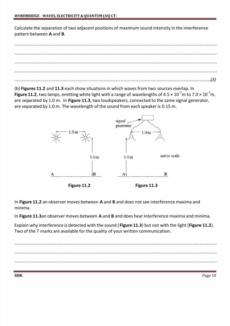
(b) Figures 11.2 and 11.3 each show situations in which waves from two sources overlap. In
Figure 11.2, two lamps, emitting white light with a range of wavelengths of 4.5 × 10⁻⁷
m to 7.0 × 10⁻⁷
m,
are separated by 1.0 m. In Figure 11.3, two loudspeakers, connected to the same signal generator,
are separated by 1.0 m. The wavelength of the sound from each speaker is 0.15 m.
Figure 11.2 Figure 11.3
In Figure 11.2 an observer moves between A and B and does not see interference maxima and
minima.
In Figure 11.3an observer moves between A and B and does hear interference maxima and minima.
Explain why interference is detected with the sound (Figure 11.3) but not with the light (Figure 11.2).
Two of the 7 marks are available for the quality of your written communication.
....................................................................................................................................................................
....................................................................................................................................................................
....................................................................................................................................................................
Page 11
8/3/2019 As CT2 - Waves, Electricity and Quantum - JAN 2012
http://slidepdf.com/reader/full/as-ct2-waves-electricity-and-quantum-jan-2012 11/13
WORDBRIDGE – WAVES, ELECTRICITY & QUANTUM (AS) CT:
SHK Page 11
....................................................................................................................................................................
....................................................................................................................................................................
....................................................................................................................................................................
....................................................................................................................................................................
....................................................................................................................................................................
....................................................................................................................................................................
....................................................................................................................................................................
....................................................................................................................................................................
....................................................................................................................................................................
................................................................................................................................................................ (7)
12. (a) Explain how a standing wave is formed.
....................................................................................................................................................................
....................................................................................................................................................................
....................................................................................................................................................................
....................................................................................................................................................................
....................................................................................................................................................................
....................................................................................................................................................................
....................................................................................................................................................................
....................................................................................................................................................................
....................................................................................................................................................................
................................................................................................................................................................ (4)
(question continues on next page)
Page 12
8/3/2019 As CT2 - Waves, Electricity and Quantum - JAN 2012
http://slidepdf.com/reader/full/as-ct2-waves-electricity-and-quantum-jan-2012 12/13
WORDBRIDGE – WAVES, ELECTRICITY & QUANTUM (AS) CT:
SHK Page 12
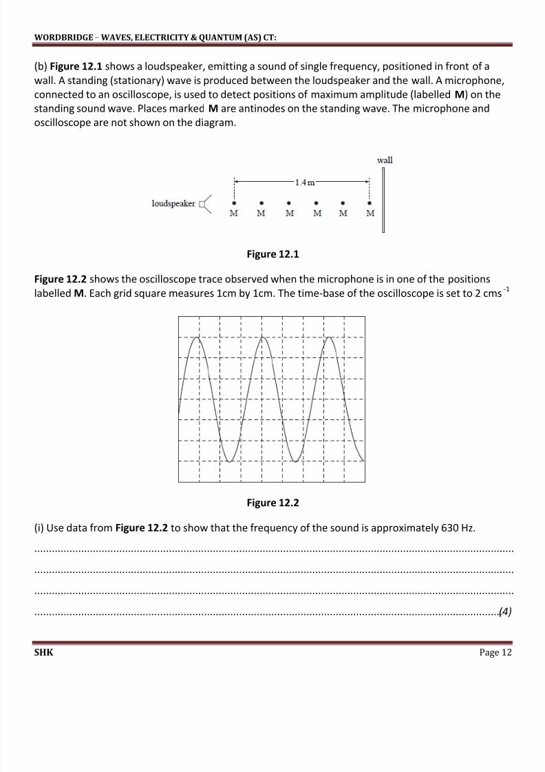
(b) Figure 12.1 shows a loudspeaker, emitting a sound of single frequency, positioned in front of a
wall. A standing (stationary) wave is produced between the loudspeaker and the wall. A microphone,
connected to an oscilloscope, is used to detect positions of maximum amplitude (labelled M) on the
standing sound wave. Places marked M are antinodes on the standing wave. The microphone and
oscilloscope are not shown on the diagram.
Figure 12.1
Figure 12.2 shows the oscilloscope trace observed when the microphone is in one of the positions
labelled M. Each grid square measures 1cm by 1cm. The time-base of the oscilloscope is set to 2 cms-1
Figure 12.2
(i) Use data from Figure 12.2 to show that the frequency of the sound is approximately 630 Hz.
....................................................................................................................................................................
....................................................................................................................................................................
....................................................................................................................................................................
................................................................................................................................................................ (4)
Page 13
8/3/2019 As CT2 - Waves, Electricity and Quantum - JAN 2012
http://slidepdf.com/reader/full/as-ct2-waves-electricity-and-quantum-jan-2012 13/13
WORDBRIDGE – WAVES, ELECTRICITY & QUANTUM (AS) CT:
SHK Page 13
(ii) Use data from Figure 6 to find the wavelength of the sound.
....................................................................................................................................................................
....................................................................................................................................................................
....................................................................................................................................................................
................................................................................................................................................................ (2)
(iii) Calculate the speed of sound in air.
....................................................................................................................................................................
....................................................................................................................................................................
................................................................................................................................................................ (2)
TOTAL FOR THIS PAPER: 80 MARKS