28
Aus- und Weiterbildung GmbH ELABOTrainingsSysteme ELABOTrainingsSysteme ® www.elabo-ts.com AS-i Fieldbus Technology
| Date post: | 26-Jul-2018 |
| Category: |
Documents |
| Upload: | trinhthuan |
| View: | 220 times |
| Download: | 0 times |

Aus- und Weiterbildung GmbH ELABOTrainingsSystemeELABOTrainingsSysteme
®
www.elabo-ts.com
AS-i Fieldbus Technology

2
From theory to practice
Source: Siemens AG
Source: Siemens AG

ELABOTrainingsSystemeELABOTrainingsSysteme
®

4
P R O F I
B U SPROCESS FIELD BUS
P R O F I
N E TINDUSTRIAL ETHERNET
From PROFINET and PROFIBUSto the AS-Interface
AS-Interface (Actuator Sensor Interface, AS-i) is a simple way of industrial networking. Due to its simplicity, this bus system is more economic, more fl exible and much easier to accomplish than any other conventio-nal parallel wiring. It is mainly used in automa-tion. Digital as well as analogue terminal de-vices can be connected. No special wiring is necessary, as almost all cable types can be used for this pur-pose. It is however of advantage to utilize the yellow AS-Interface fl at cable as it transfers
Industrial Communication
Source: Siemens AG

ELABOTrainingsSystemeELABOTrainingsSysteme
®
5
ASI Safe
to 100 m, it can however be ex-tended to 600 m by implementing repeaters or extenders. Digital as well as analogue modules can be connected.
AS-i network, are referred to as Slaves. Up to 62 Slaves can be addressed in a network.Communication modules, signal lights and motor starters count among the actuators. The sensors might be capacitive or inductive, light curtains, laser scan-ners or emergency-stop buttons.
ASI Safe (AS-Interface Safe-ty at Work)
Safety monitors and safe Slaves are used to bring an AS-i network into a safe condition. They are me-rely connected to the system run-ning on the same cable. A safe network can thus be integ-rated in a conventional network or form part of it without any further requirements.
and preparing the cable fi rst. If a module is removed the cable jacket automatically reseals itself and the insulation is restored. The network length is limited
The AS-i Master
The AS-i Master has the control and monitoring functions in an AS-i network. It communicates with the connected modules ex-changing all the relevant data with the so-called host. This is most commonly a module con-nected with the control, as e. g. an AS-i communication processor on a PLC. In the master standard operation, in addition to the sla-ve address 4 bits of output data are transferred to all the Slaves by a Master call during the data exchange phase. The Slave con-cerned responds to the call trans-ferring 4 bits of input data. The Master call enforces a check of all the Slaves in ascending order of the addresses. This procedure, which is cons-tantly repeated during the cyclical standard operation of the Master, is referred to as Master-Slave polling. Failing Slaves can be re-placed and readdressed by the Master.
The AS-i Slaves
All sensors, actuators and mo-dules, which are integrated in an
both power and data. The so-called cable piercing tech-nology allows AS-Interfacemodules to be installed anywhe-re on the network without cutting
The topology of an AS-i net-work is free-ly selectable. Bus, star, ring or tree structures are possible. More- over, a new segment can be started at any point of the bus.
What is AS-Interface?

6
P R O F I
B U SPROCESS FIELD BUS
P R O F I
N E TINDUSTRIAL ETHERNET
AS-i Addressing Unit
Transfer System with AS-i Pneumatic Module
Transfer System with AS-i Connection Module DI/DO
PLC Board 24 V with LOGO!and AS-i Expansion Module
Automation Board S7-315F-2PN/DP
AS-i PneumaticModule
AS-i Command/Message Module
AS-i SignalingColumn
Field Bus Technology − Overview
ELABOTrainingsSystemeELABOTrainingsSysteme
®
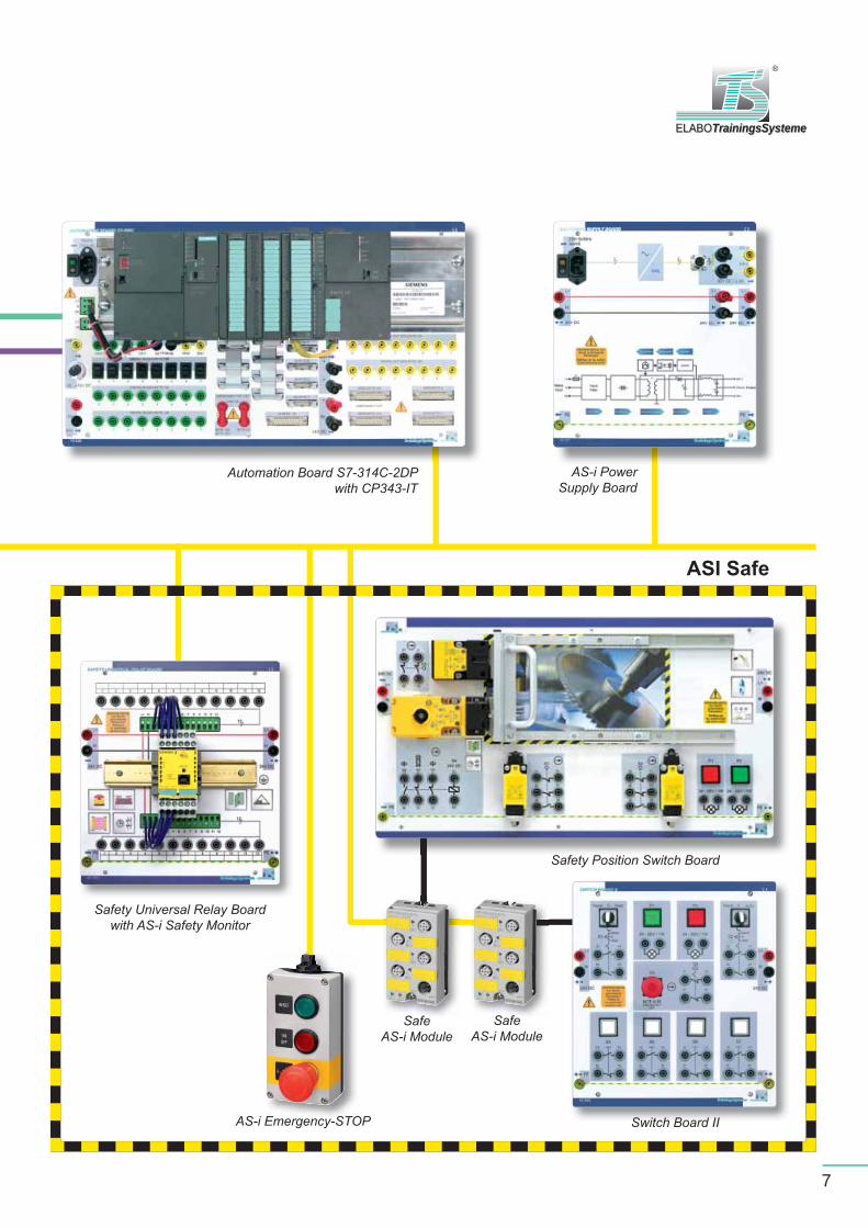
7
AS-i Emergency-STOP
SafeAS-i Module
AS-i Power Supply Board
Switch Board II
Safety Universal Relay Boardwith AS-i Safety Monitor
Automation Board S7-314C-2DPwith CP343-IT
SafeAS-i Module
Safety Position Switch Board
ASI Safe

8
AS-Interface Master
Automation Board S7 315F
70 230 Automation Board S7 315F-2PN/DP
1 power supply 24 V/5 A
1 CPU 314C-2DP with the integrated features:
- fail-safe PLC with PROFINET and PROFIBUS DP communication interfaces
24 digital inputs, 16 digital outputs
4 analog inputs, 2 analog outputs
1 Automation Board S7 / 300C
expanded with:
70 007 AS-i communication processor CP 343-2
70 230 Automation Board S7 315F-2PN/DP with70 007 AS-i communication processor
Learning Objectives:
Setup and design of a PLC
Commissioning an automation system
Programming in accordance with international standard IEC1131-3
Connecting and commissioning field bus systems
ELABOTrainingsSystemeELABOTrainingsSysteme
®
9
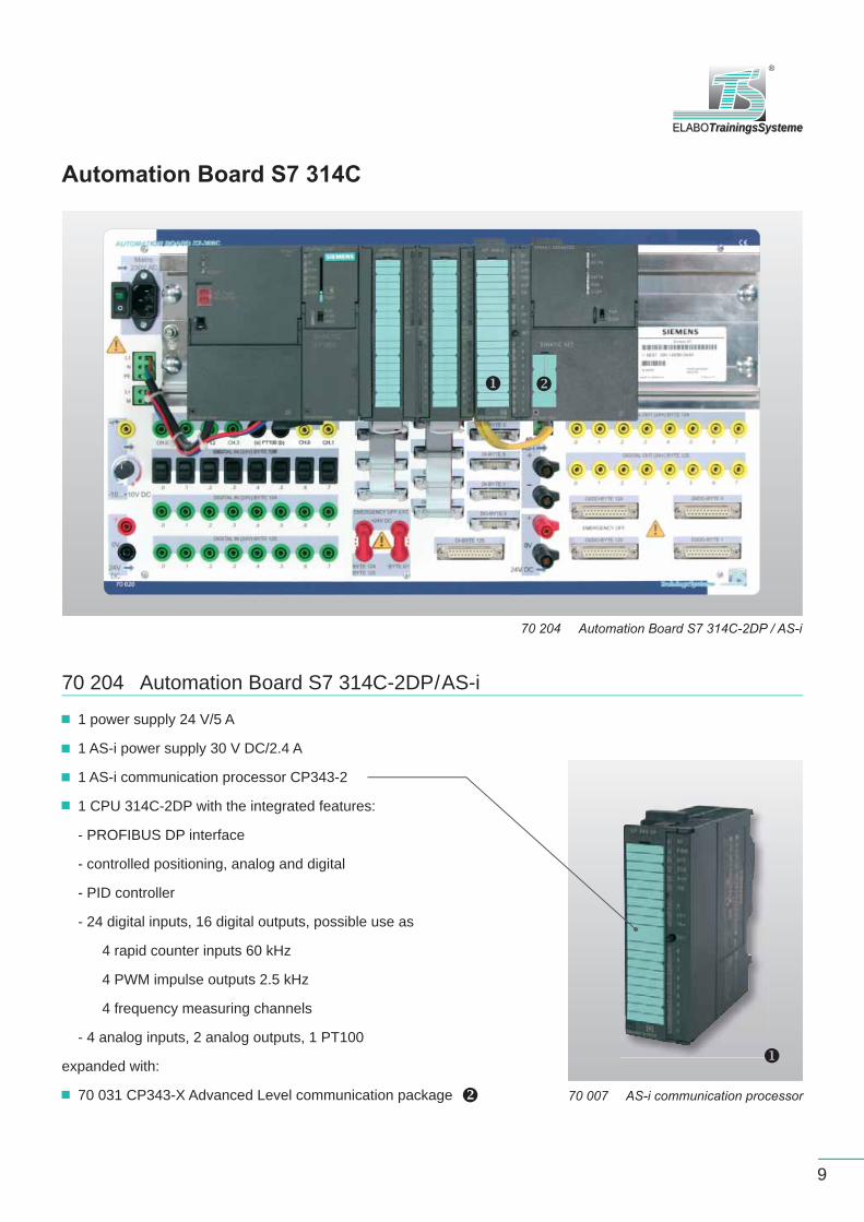
Automation Board S7 314C
70 204 Automation Board S7 314C-2DP / AS-i
70 204 Automation Board S7 314C-2DP/AS-i
1 power supply 24 V/5 A
1 AS-i power supply 30 V DC/2.4 A
1 AS-i communication processor CP343-2
1 CPU 314C-2DP with the integrated features:
- PROFIBUS DP interface
- controlled positioning, analog and digital
- PID controller
- 24 digital inputs, 16 digital outputs, possible use as
4 rapid counter inputs 60 kHz
4 PWM impulse outputs 2.5 kHz
4 frequency measuring channels
- 4 analog inputs, 2 analog outputs, 1 PT100
expanded with:
70 031 CP343-X Advanced Level communication package 70 007 AS-i communication processor

10
Use in a transfer system
Transfer systems with AS-i modules
80 590 Transfer system 24 V DC with78 108 AS-i connection module 4DI/4DO
80 590 Transfer System 24 V DC
24 V DC gear motor, 2 directions of rotation, locked
Integrated PWM motor control with overload protection
Analogue continuous speed control, also by external signal, 0 - 10 V
Digital control, rapid traverse
2 integrated detection modules for end position recognition, with 2-wire sensor,
M12 connectors and supporting brackets
M12 8-fold interface for connection of automatic systems, sensors, actuators, etc.
for use as inputs or outputs
- 8 x M12, double assignment possible
- 1 x SUB D 25-pin
System connection SUB D 25-pole to Automation Board S7/300C
- separate control current circuits of sensors/actuators for safety-relevant functions
DC control unit:
Control panel for external tapping/feeding of signals, power supply
Commissioning by switches, potentiometers on control panel
12 x 4 mm safety sockets
Length = 750 mm, width = 160 mm, track = 120 mm

ELABOTrainingsSystemeELABOTrainingsSysteme
®
11
80 590 Transfer system with 78 104 Pneumatic module,78 107 Command/message Module and 78 108 AS-i connection module 4DI/4DO
78 108 AS-i Connection Module 4DI/4DO
4 inputs 24 V DC
4 outputs 2 A, 24 V DC
78 104 Pneumatic Module 2PO
2 inputs DI 24 V
2 pneumatic outputs (2 3/2-way valves)
Inputs for 2- and 3-wire sensors
Function display for bus, in- and outputs
Direct connection of pneumatic cylinders
78 107 Command/Message Module
2 buttons with integrated signal lamps, green and red, 2DI/2DO

12
Fail-safe fi eld bus AS-i
AS-i Power Supply Board
78 021 AS-I Power Supply with Data Decoupling
78 021 AS-i Power Supply
M12 connection for AS-i slaves Looping-through and contacting of the 24 DC load supply via 4 mm safety jacks or pole terminals
Output voltage: 30 V AS-i Output current: 2.4 A max. Output power: 72 W
Input voltage: 230 V, 50/60 Hz
40 076 Safe AS-i Emergency-STOP
40 076 Safe AS-i Emergency-STOP
1 emergency-stop pushbutton via separate fail-safe slave, 2 FDI
2 pushbuttons, illuminated, via separate slave, 2DI/2DO Simple direct connection of proven operating elements to ASI Safe
Accessories
40 078 Safe AS-i Slave
40 078 Safe AS-i Slave
2 fail-safe inputs, 2FDI 2 digital outputs, 2DO, 24 V/2 A
Mounted on holding plate

13
ELABOTrainingsSystemeELABOTrainingsSysteme
®
40 016 PLC Board 24 V
equipped with LOGO! 12/24RC
12 inputs, 8 outputs
2 connections for bus systems
8 push/lock-in switches for input simulation
2 additional outputs for 24 V power supply of add-on components
PLC Board 24 V
40 016 PLC Board 24 V with LOGO! and40 025 AS-i Expansion Module
40 025 AS-i Expansion Module
4 virtual digital in- and outputs
Learning Objectives:
Parameterization of logical modules
Fundamentals of digital technology
Programming with the operator
elements
Programming with the PC 40 025 AS-i Expansion module
LOGO! 12/24RC
Integrated backlit display fi eld and operator control panel
Integrated EEPROM memory for control program and internal setpoint values
8 integrated time switching clocks
4 relay outputs 10 A max. - 10 A (with resistive load) - 3 A (with inductive load)
Short circuit protection by external fusing
8 inputs
14
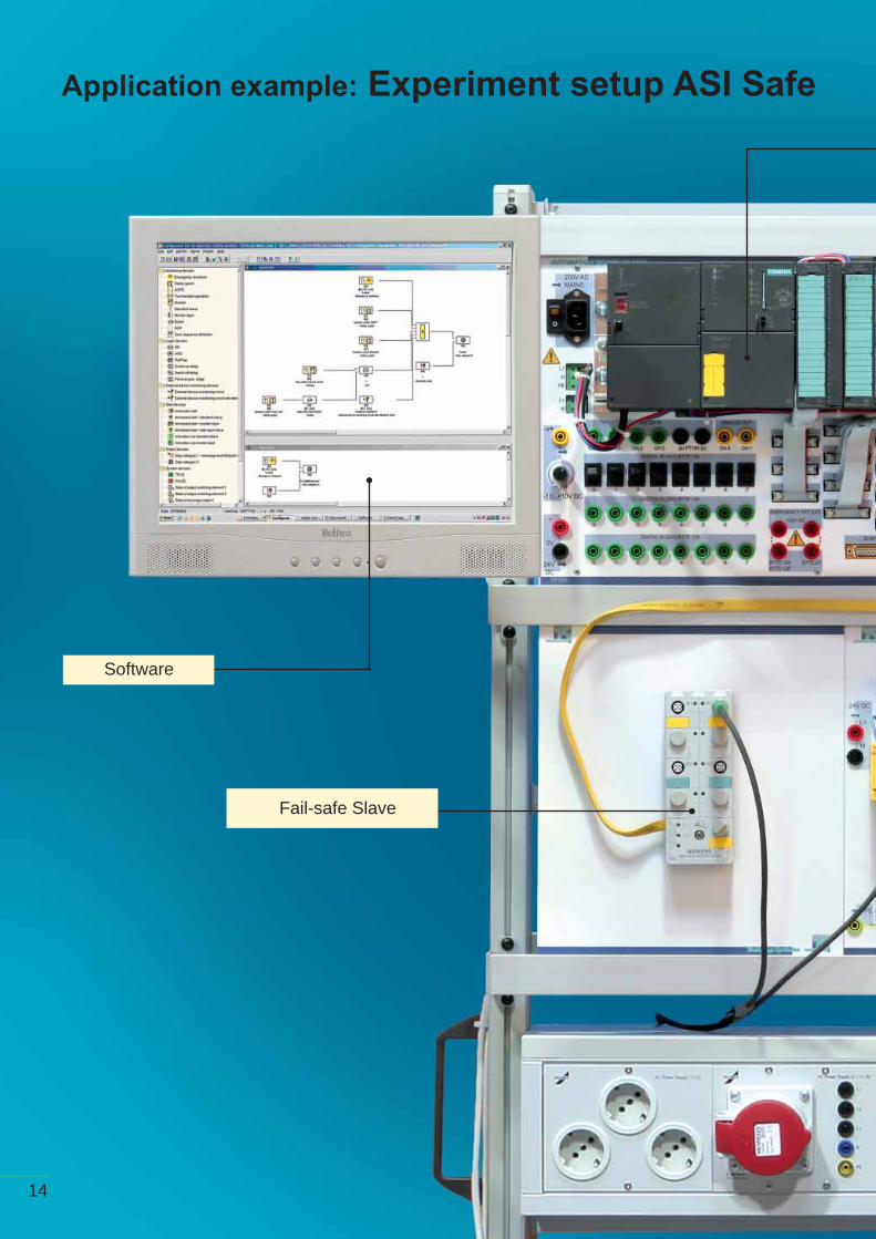
Application example: Experiment setup ASI Safe
Software
Fail-safe Slave

ELABOTrainingsSystemeELABOTrainingsSysteme
®
15
AS-i Master
Safety Monitor
Safety Position Switch Board
16
Fail-safe fi eld bus AS-i
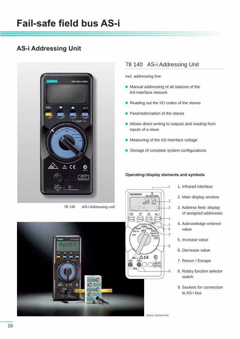
AS-i Addressing Unit
78 140 AS-i Addressing unit
78 140 AS-i Addressing Unit
incl. addressing line
Manual addressing of all stations of the AS-Interface network
Reading out the I/O codes of the slaves
Parameterization of the slaves
Allows direct writing to outputs and reading from inputs of a slave
Measuring of the AS-Interface voltage
Storage of complete system confi gurations
1. Infrared interface
2. Main display window
3. Address fi eld: display of assigned addresses
4. Acknowledge entered value
5. Increase value
6. Decrease value
7. Return / Escape
8. Rotary function selector switch
9. Sockets for connection to AS-i bus
Operating/display elements and symbols
Source: Siemens AG

ELABOTrainingsSystemeELABOTrainingsSysteme
®
17
Accessories
78 050 AS-i Shaped Cable, Yellow (data)
80 051 AS-i Shaped Cable, Black (power)
100 m each
Protection against reverse polarity due to trapezoidal shape
Optimized material allows use in various ambient conditions
Rapid exchange and connection to AS-Interface with piercing technology
Self-sealing: protection class IP67, even after disconnecting
AS-i Shaped Cables
78 103 Analog Output Module 2 AO
incl. aluminium exchange cassette and fastening material 2 AO 0…10 V
78 052 AS-i Branch
40 077 M12/4 mm Connecting Cables
2 adapter cables with M12 jack at one, 4 mm safety jacks at the other end Length: 0.5 m
80 053 M12 Connecting Cable
to connect e.g. AS-i proximity switch Length: 0.5 m
78 109 Top-hat Rail Mounting Plate for Compact Modules
incl. mounting kit
80 703 Set of Fastening Material for Sensors
2 slot nuts 2 M4 threaded screws
80 704 Sensor Mounting System
Profi le girder for setting up test stations at any free place on the transfer system
to connect slaves with M12 cables
80 150 AS-i Proximity Switch, Ind.
Switching distance: 5 mm Diameter: 18 mm Switching function: NC/NO

18
Teachware
E78 952CD Manual Trainer Section Applications of the fi eld bus system AS-i with S7-300
E78 953CD Manual Practical ExperimentsApplications of the fi eld bus system AS-i with S7-300
Contents
1. Task2. Required components3. Setup plan4. Programming the slave5. Confi guring or expanding and testing the AS-i network6. Connecting sensors/actuators7. Programming the PLC7.1 Background7.2 Creating a project7.3 Designing a program8. Testing the program9. Optimizing the program
Project 1: Sensor-controlled belt driveProject 2: Button-controlled belt driveProject 3: Material detectionProject 4: Use of a stop cylinderProject 5: Analogue value processingPrinted and digital!
Applications of the fi eld bus system AS-i with S7-300
Applications of the fi eld bus system AS-i with S7-300
Trainer Section Practical Experiments
Manual
19
ELABOTrainingsSystemeELABOTrainingsSysteme
®
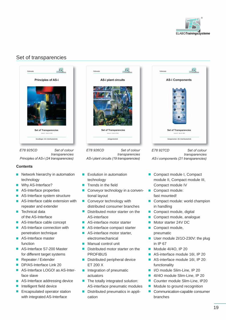
E78 925CD Set of colour transparencies
Principles of AS-i (24 transparencies)
E78 926CD Set of colour transparencies
AS-i plant circuits (19 transparencies)
E78 927CD Set of colour transparencies
AS-i components (21 transparencies)
Set of transparencies
Network hierarchy in automation technologyWhy AS-Interface?AS-Interface propertiesAS-Interface system structureAS-Interface cable extension with repeater and extenderTechnical data of the AS-InterfaceAS-Interface cable concept AS-Interface connection with penetration techniqueAS-Interface master functionAS-Interface S7-200 Master for different target systemsRepeater / Extender DP/AS-Interface Link 20 AS-Interface LOGO! as AS-Inter-face slave AS-Interface addressing deviceIntelligent fi eld deviceEncapsulated operator station with integrated AS-Interface
Evolution in automation technologyTrends in the fi eldConveyor technology in a conven-tional layoutConveyor technology with distributed consumer branchesDistributed motor starter on the AS-interfaceAS-interface motor starterAS-interface compact starterAS-interface motor starter, electromechanicalManual control unitDistributed motor starter on the PROFIBUSDistributed peripheral device ET 200 XIntegration of pneumatic actuators The totally integrated solution: AS-interface pneumatic modules Distributed pneumatics in appli-cation
Contents
Compact module I, Compact module II, Compact module III, Compact module IVCompact module: fast mounted!Compact module: world champion in handlingCompact module, digitalCompact module, analogueMotor starter 24V DCCompact module, pneumaticUser module 2I/1O-230V: the plug in IP 67Module 4I/4O, IP 20AS-interface module 16I, IP 20AS-interface module 16I, IP 20: functionalityI/O module Slim-Line, IP 204I/4O module Slim-Line, IP 20Counter module Slim-Line, IP20Module to ground recognitionCommunication-capable consumer branches
Principles of AS-i AS-i plant circuits AS-i Components
Set of Transparencies Set of Transparencies Set of Transparencies
20
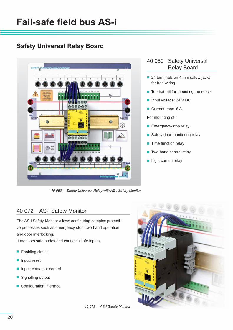
Safety Universal Relay Board
Fail-safe fi eld bus AS-i
40 050 Safety Universal Relay Board
24 terminals on 4 mm safety jacks for free wiring
Top-hat rail for mounting the relays
Input voltage: 24 V DC
Current: max. 6 A
For mounting of:
Emergency-stop relay
Safety door monitoring relay
Time function relay
Two-hand control relay
Light curtain relay
40 072 AS-i Safety Monitor
40 072 AS-i Safety Monitor
The AS-i Safety Monitor allows confi guring complex protecti-
ve processes such as emergency-stop, two-hand operation
and door interlocking.
It monitors safe nodes and connects safe inputs.
Enabling circuit
Input: reset
Input: contactor control
Signalling output
Confi guration interface
40 050 Safety Universal Relay with AS-i Safety Monitor
21
ELABOTrainingsSystemeELABOTrainingsSysteme
®
40 073 Parameterization Software
for the AS-i safety monitor
Single licence
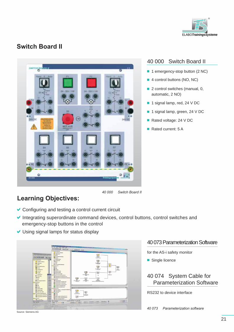
40 000 Switch Board II
1 emergency-stop button (2 NC)
4 control buttons (NO, NC)
2 control switches (manual, 0, automatic, 2 NO)
1 signal lamp, red, 24 V DC
1 signal lamp, green, 24 V DC
Rated voltage: 24 V DC
Rated current: 5 A
Switch Board II
Learning Objectives:
Configuring and testing a control current circuit
Integrating superordinate command devices, control buttons, control switches and emergency-stop buttons in the control
Using signal lamps for status display
40 000 Switch Board II
40 073 Parameterization software
40 074 System Cable for Parameterization Software
RS232 to device interface
Source: Siemens AG
22
Fail-safe fi eld bus AS-i
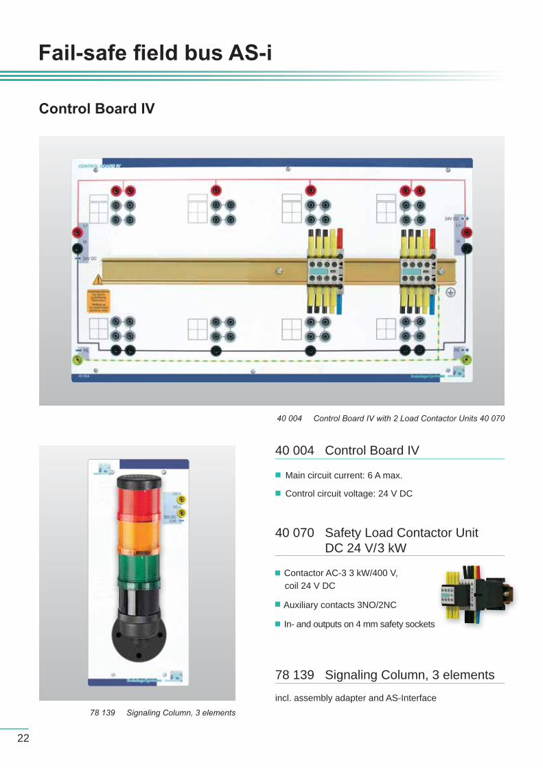
40 004 Control Board IV
Main circuit current: 6 A max.
Control circuit voltage: 24 V DC
40 070 Safety Load Contactor Unit DC 24 V/3 kW
Contactor AC-3 3 kW/400 V, coil 24 V DC
Auxiliary contacts 3NO/2NC
In- and outputs on 4 mm safety sockets
Control Board IV
78 139 Signaling Column, 3 elements
incl. assembly adapter and AS-Interface78 139 Signaling Column, 3 elements
40 004 Control Board IV with 2 Load Contactor Units 40 070
23
ELABOTrainingsSystemeELABOTrainingsSysteme
®
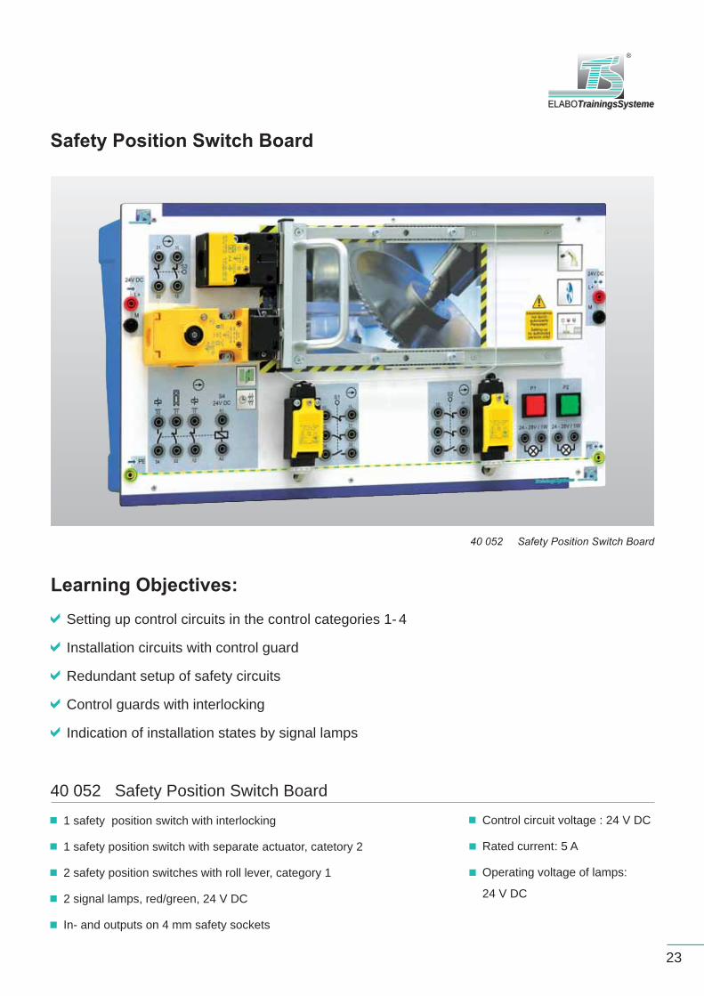
Safety Position Switch Board
40 052 Safety Position Switch Board
1 safety position switch with interlocking
1 safety position switch with separate actuator, catetory 2
2 safety position switches with roll lever, category 1
2 signal lamps, red/green, 24 V DC
In- and outputs on 4 mm safety sockets
Control circuit voltage : 24 V DC
Rated current : 5 A
Operating voltage of lamps:
24 V DC
Learning Objectives:
Setting up control circuits in the control categories 1- 4
Installation circuits with control guard
Redundant setup of safety circuits
Control guards with interlocking
Indication of installation states by signal lamps
40 052 Safety Position Switch Board

24
Teachware
Manual
Contents
Introduction: The fail-safe bus system AS-i 1. Principles of the system2. Transmission-relevant hardware structure of the bus users3. Data transfer of the fail-safe slaves4. Function and operating modes5. Master evaluation of the data provided by the AS-i fault monitor6. Display and operating elements7. Confi guration software8. System components9. Diagnostics options10. Evaluation of the confi gured components (time and function)11. Technical data
ApplicationsEmergency-Stop monitoring / Safety door monitoring / documentation
Printed and digital!
E40 541CD Manual Practical ExperimentsFail-safe bus system AS-i
E40 540CD Manual Trainer SectionFail-safe bus system AS-i
Fail-safebus system AS-i
Fail-safebus system AS-i
Trainer Section Practical Experiments

ELABOTrainingsSystemeELABOTrainingsSysteme
®
25
E40 542CD Set of transparenciesFail-safe bus system AS-i
E40 503CD Set of transparenciesSafety technology – General Information
TechnoCards
E40 546 Set of TechnoCards, consisting of
E40 547AS-i fault monitor
E40 548 Confi guration of a fail-safe AS-i bus system
Set of transparencies
The principle IThe principle IIThe conceptPrinciple structure ISignifi cation of the master call and slave response bitsPrinciple structure IIPrinciple structure IIIPrinciple structure IVSafety monitor ISafety monitor IIDisplay and operating elementsTerminal array / block diagramSetup with external supply
Confi guration softwareEvaluation process of the confi gured componentsSystem componentsOnline diagnosisBenefi t of using a fail-safe AS-i bus systemEmergency-stop monitoring, control category 4Safety door monitoring, control category 2Safety door monitoring, control category 4Functional expansionTechnical data
Set of transparencies
Safety technologyGeneral Information
Set of Transparencies
Set of Transparencies
Fail-safebus system AS-i
E40 503CD Set of transparencies Safety techno-logy – General Information

26
Information and consultation
in all questions concerning the equipment for
vocational and higher technical education
on site
over the telephone
We will support you ...
Contact
ELABO TrainingsSysteme GmbH
Servicecenter
Im Hüttental 11
85125 Kinding / Germany
Tel.: +49 (0)8467/ 84 04 - 0
Fax: +49 (0)8467/ 84 04 44
www.elabo-ts.com
Consultancy
Experience
Selection of products complying with syllabuses
Comprehensive system determination
Servicecenter - we will call you back
and support you in planning and project
development
Classroom layout concepts
Ergonomic workplace design
Customized offers
Information about our products / manuals
Planning of seminars
Comprehesive range of innovative products,
systems and solutions
Quality service from fi rst consultation
to delivery and beyond
Trainer-seminars / Inhouse-trainings
Industrial training institutions
Vocational schools / technical collgeges
Chambers of commerce
Academies / Universities
Projects and references
Where this catalogue ends,we start consulting ...
27
Trainer Packages
ELABOTrainingsSystemeAus- und Weiterbildung GmbH
Im Hüttental 1185125 Kinding - Germany
Tel: +49 (0) 84 67 / 84 04 - 0Fax: +49 (0) 84 67 / 84 04 44
Your enquiry
Name, position
Company / institution / authority
Street, PO Box
Post code, town/city, country
Telephone, telefax e-mail
Please send us the following catalogue(s):
CommunicationSystemsISDN and analog
Drive TechnologyControl TechnologySafety of Electric Installations and Devices
Trainer PackagesThe solution
System andProcess-Simulation
Microcontroller Technology
Practical Training in Sensor Technology
Home and Building Control KNX/EIB
Electrical EngineeringElectronics / Digital Technology
Gear Unit Technology
Operator Control and Monitoring
Subject to technical modifi cations and further developments 09/2009.
Cop
y an
d fa
x
Bus-capableIntercoms
Energy Measuring Technology
ElaboTrainingSystems
Gear Unit TechnologySystem andProcess-SimulationMicrocontroller TechnologyHome and Building Control
KNX/EIB
Bus-capable IntercomsControl Technology Drive Technology
Electrical Engineering Electronics / Digital Technology
Operator Control and MonitoringHuman Machine Interface
Communication SystemsISDN and analog
Safety of Electric Installations and Devices
The Solution
Practical Training in Sensor Technology
Energy Measuring Technology

Aus- und Weiterbildung GmbH ELABOTrainingsSystemeELABOTrainingsSysteme
®
ELABOTrainingsSysteme GmbHIm Hüttental 1185125 Kinding / Germany
Tel.: +49 (0) 84 67 / 84 04 - 0Fax: +49 (0) 84 67 / 84 04 44e-mail: [email protected]: www.elabo-ts.com


