ASEE 2014 Zone I Conference, April 3-5, 2014, University of Bridgeport, Bridgeport, CT, USA. Object Tracking Using Autonomous Quad Copter Carlos A. Munoz Robotics, Intelligent Sensing & Control (RISC) Laboratory, School of Engineering, University of Bridgeport, 221 University Avenue, Bridgeport, CT 06604, USA. [email protected], Abstract - To have a quad copter autonomously catch (tap) an object by receiving XYZ coordinates given by means of object detection using two cameras. This will be tested in a two-step process. First test is done on a flat surface (table) and the second test is done on the air. Keywords — autonomous tracking; image processing; object detection; quad copter; I. INTRODUCTION The goal of this work is to create a program that can attempt to simulate a catcher. This will be attempted using a quad copter “Fig. 1.” that will mimic the action of a catcher. The idea came from watching kids always playing by themselves throwing the ball to a wall or to the air and having to go and get the ball themselves. What if we can use a “bot” to pick the ball up or hit the ball back automatically based on location of such ball? This can be useful in areas like golf, where “bots” can be sent to pick all the golf balls and return them back to a central location. Or a concept for a bot that acts like a dog and catches the ball in the air. The objective of this work is to show a way of acquiring such feat. II. RELATED WORK The very first places where this idea came from was from a segment in TEDGlobal, by Raffaello D’Andrea [1] called “The astounding athletic power of quadcopters”. Here he explains how we can use and manipulate quad copters to our advantage; how they can be agile and swift to fulfill our needs without sacrificing performance and with redundancy capabilities. Another piece that inspired this paper was the work done by Armin Ambühl [2]. In his experiment, he manipulates quad copters using a Kinect as a guidance tool. His work was also supervised by Raffaello. In today’s world, autonomous quad copters are being utilized more often as cheaper more efficient alternatives. The Olympics [3] are a good example. In the past, helicopters were used to get the “perfect angles” during competitions. In the recent Olympics it was all done by quad copters. The route and length of time is set up per quad and off they go to get the same angles that the helicopters did at a much cheaper price. There are even some future jobs that could potentially be replaced by quad copters such as firefighters [4] and delivery of Amazon packages [5] just to name a few. Fig. 1.Quad copter used in this work III. HARDWARE A. Quad Copter In this work, there are three main items that are used in conjunction to achieve the end result. These parts are one quad copter made by 3D Robotics [6] and two Kinects [7] made by Microsoft. The quad copter contains four motors with four blades. Two blades spin counter clockwise and two that spin clockwise. There are 4 esc’s (electronic speed controllers) that govern the speed of the motors. The quad also comes with a power distribution board, a battery (4200mAh) and an APM (auto pilot module) that combined with the GPS one can achieve autonomy via setting a route on a map for the quad to go and come if needed be. There is also a telemetry radio module that is constantly sending information (altitude, speed, location battery level, etc.) from the quad to the pc and another telemetry radio on the pc connected via USB that sends pitch, jaw, and roll alterations to the quad. They are both send/receive modules. B. Kinect The Kinect cameras “Fig. 3” are made by Microsoft. They contain three main functions. There is a depth stream that is mainly used to give an approximation on how far an object is from the Kinect. There is also a skeleton tracking module that is mainly used to detect humans in front of the Kinect. There is
Transcript
ASEE 2014 Zone I Conference, April 3-5, 2014, University of Bridgeport, Bridgeport, CT, USA.
Object Tracking Using Autonomous Quad Copter Carlos A. Munoz
Robotics, Intelligent Sensing & Control (RISC) Laboratory, School of Engineering, University of Bridgeport,
221 University Avenue, Bridgeport, CT 06604, USA. [email protected],
Abstract - To have a quad copter autonomously catch (tap) an object by receiving XYZ coordinates given by means of object detection using two cameras. This will be tested in a two-step process. First test is done on a flat surface (table) and the second test is done on the air.
I. INTRODUCTION The goal of this work is to create a program that can
attempt to simulate a catcher. This will be attempted using a quad copter “Fig. 1.” that will mimic the action of a catcher. The idea came from watching kids always playing by themselves throwing the ball to a wall or to the air and having to go and get the ball themselves. What if we can use a “bot” to pick the ball up or hit the ball back automatically based on location of such ball? This can be useful in areas like golf, where “bots” can be sent to pick all the golf balls and return them back to a central location. Or a concept for a bot that acts like a dog and catches the ball in the air. The objective of this work is to show a way of acquiring such feat.
II. RELATED WORK The very first places where this idea came from was from a
segment in TEDGlobal, by Raffaello D’Andrea [1] called “The astounding athletic power of quadcopters”. Here he explains how we can use and manipulate quad copters to our advantage; how they can be agile and swift to fulfill our needs without sacrificing performance and with redundancy capabilities. Another piece that inspired this paper was the work done by Armin Ambühl [2]. In his experiment, he manipulates quad copters using a Kinect as a guidance tool. His work was also supervised by Raffaello.
In today’s world, autonomous quad copters are being
utilized more often as cheaper more efficient alternatives. The Olympics [3] are a good example. In the past, helicopters were used to get the “perfect angles” during competitions. In the recent Olympics it was all done by quad copters. The route and length of time is set up per quad and off they go to get the same angles that the helicopters did at a much cheaper price.
There are even some future jobs that could potentially be replaced by quad copters such as firefighters [4] and delivery of Amazon packages [5] just to name a few.
Fig. 1.Quad copter used in this work
III. HARDWARE A. Quad Copter
In this work, there are three main items that are used in conjunction to achieve the end result. These parts are one quad copter made by 3D Robotics [6] and two Kinects [7] made by Microsoft. The quad copter contains four motors with four blades. Two blades spin counter clockwise and two that spin clockwise. There are 4 esc’s (electronic speed controllers) that govern the speed of the motors. The quad also comes with a power distribution board, a battery (4200mAh) and an APM (auto pilot module) that combined with the GPS one can achieve autonomy via setting a route on a map for the quad to go and come if needed be. There is also a telemetry radio module that is constantly sending information (altitude, speed, location battery level, etc.) from the quad to the pc and another telemetry radio on the pc connected via USB that sends pitch, jaw, and roll alterations to the quad. They are both send/receive modules. B. Kinect
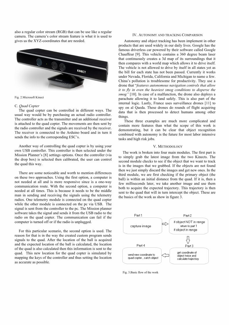
The Kinect cameras “Fig. 3” are made by Microsoft. They contain three main functions. There is a depth stream that is mainly used to give an approximation on how far an object is from the Kinect. There is also a skeleton tracking module that is mainly used to detect humans in front of the Kinect. There is
also a regular color stream (RGB) that can be use like a regular camera. The camera’s color stream feature is what it is used to gives us the XYZ-coordinates that are needed.
Fig. 2.Microsoft Kinect C. Quad Copter
The quad copter can be controlled in different ways. The usual way would be by purchasing an actual radio controller. The controller acts as the transmitter and an additional receiver is attached to the quad copter. The movements are then sent by the radio controller and the signals are received by the receiver. The receiver is connected to the Arduino board and in turn it sends the info to the corresponding ESC’s.
Another way of controlling the quad copter is by using your
own USB controller. This controller is then selected under the Mission Planner’s [8] settings options. Once the controller (via the drop box) is selected then calibrated, the user can control the quad this way.
There are some noticeable and worth to mention differences
on these two approaches. Using the first option, a computer is not needed at all and is more responsive since is a one-way communication route. With the second option, a computer is needed at all times. This is because it needs to be the middle man in sending and receiving the signals using the telemetry radios. One telemetry module is connected on the quad copter while the other module is connected on the pc via USB. The signal is sent from the controller to the pc. The Mission planner software takes the signal and sends it from the USB radio to the radio on the quad copter. The communication can fail if the computer is turned off or if the radio is unplugged.
For this particular scenario, the second option is used. The
reason for that is in the way the created custom program sends signals to the quad. After the location of the ball is acquired and the expected location of the ball is calculated, the location of the quad is also calculated then this information is sent to the quad. This new location for the quad copter is simulated by mapping the keys of the controller and thus setting the location as accurate as possible.
IV. AUTONOMY AND TRACKING COMPARISON Autonomy and object tracking has been implement in other
products that are used widely in our daily lives. Google has the famous driverless car powered by their software called Google Chauffeur [9]. This vehicle contains a 360 degree beam laser that continuously creates a 3d map of its surroundings that it then compares with a world map which allows it to drive itself. The vehicle is not allowed to drive by itself in all states yet as the bill for each state has not been passed. Currently it works under Nevada, Florida, California and Michigan to name a few. China’s pollution is troublesome for productivity. They use a drone that “features autonomous navigation controls that allow it to fly in even the heaviest smog conditions to disperse the smog” [10]. In case of a malfunction, the drone also deploys a parachute allowing it to land safely. This is also part of the internal logic. Lastly, France uses surveillance drones [11] to spy on al Qaeda. These drones do rounds of flight acquiring data that is then processed to detect humans among other things.
These three examples are much more complicated and contain more features than what the scope of this work is demonstrating, but it can be clear that object recognition combined with autonomy is the future for most labor intensive tasks and high risk jobs.
V. METHODOLOGY The work is broken into four main modules. The first part is
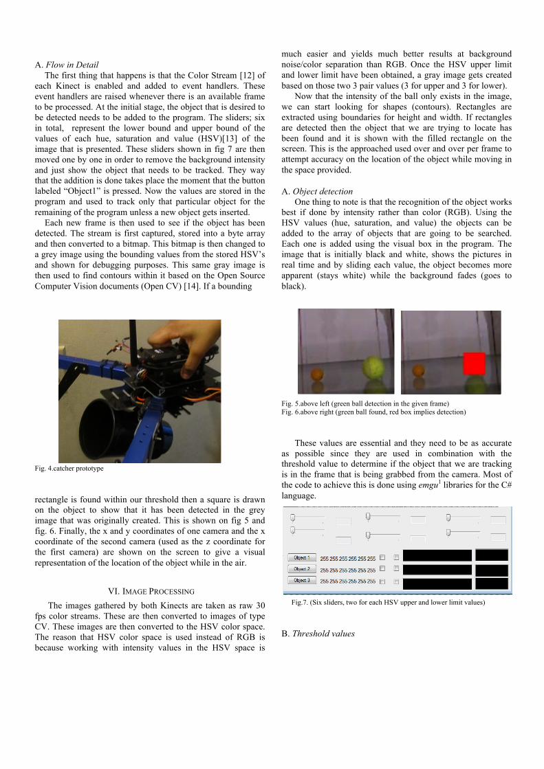
to simply grab the latest image from the two Kinects. The second module checks to see if the object that we want to track is in the images that we grabbed. If the objects are not found then we just simply discard the images and get new ones. In the third module, we are first checking if the primary object (the ball) is within an initial distance from the quad. If it is, then a few milliseconds later, we take another image and use them both to acquire the expected trajectory. This trajectory is then sent to the quad that will in turn intercept the object. These are the basics of the work as show in figure 3.
Fig. 3.Basic flow of the work
A. Flow in Detail
The first thing that happens is that the Color Stream [12] of each Kinect is enabled and added to event handlers. These event handlers are raised whenever there is an available frame to be processed. At the initial stage, the object that is desired to be detected needs to be added to the program. The sliders; six in total, represent the lower bound and upper bound of the values of each hue, saturation and value (HSV)[13] of the image that is presented. These sliders shown in fig 7 are then moved one by one in order to remove the background intensity and just show the object that needs to be tracked. They way that the addition is done takes place the moment that the button labeled “Object1” is pressed. Now the values are stored in the program and used to track only that particular object for the remaining of the program unless a new object gets inserted.
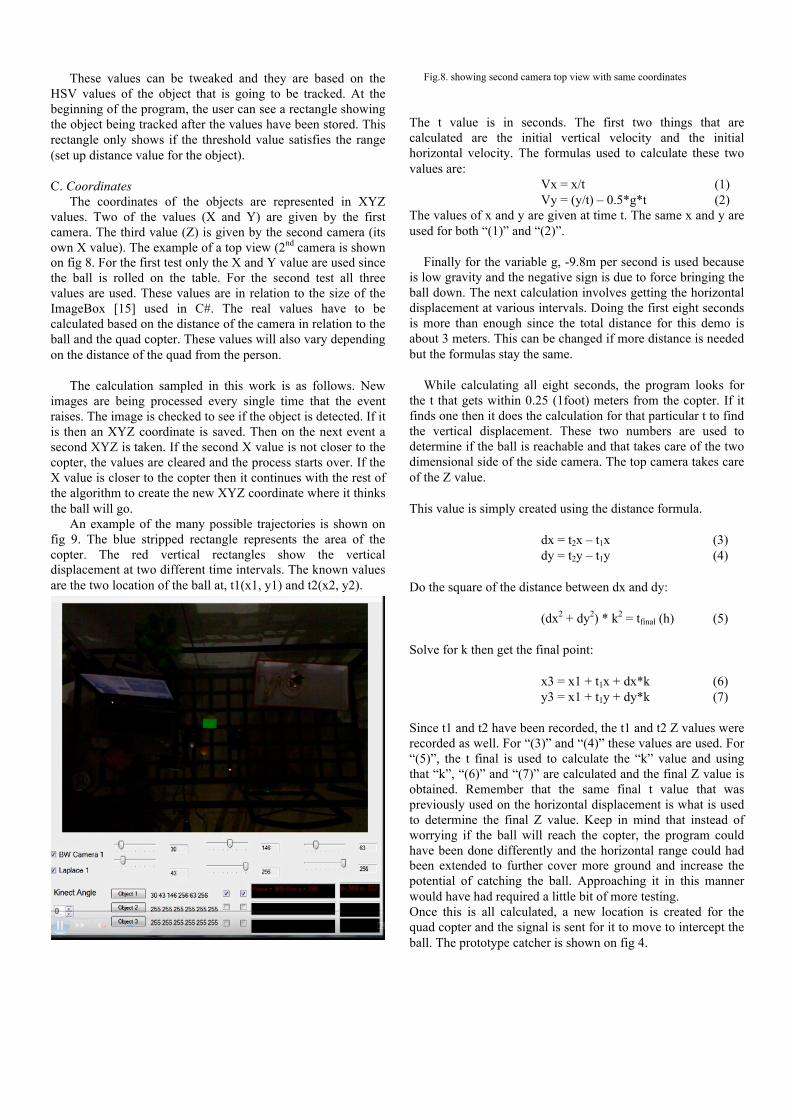
Each new frame is then used to see if the object has been detected. The stream is first captured, stored into a byte array and then converted to a bitmap. This bitmap is then changed to a grey image using the bounding values from the stored HSV’s and shown for debugging purposes. This same gray image is then used to find contours within it based on the Open Source Computer Vision documents (Open CV) [14]. If a bounding Fig. 4.catcher prototype rectangle is found within our threshold then a square is drawn on the object to show that it has been detected in the grey image that was originally created. This is shown on fig 5 and fig. 6. Finally, the x and y coordinates of one camera and the x coordinate of the second camera (used as the z coordinate for the first camera) are shown on the screen to give a visual representation of the location of the object while in the air.
VI. IMAGE PROCESSING The images gathered by both Kinects are taken as raw 30
fps color streams. These are then converted to images of type CV. These images are then converted to the HSV color space. The reason that HSV color space is used instead of RGB is because working with intensity values in the HSV space is
much easier and yields much better results at background noise/color separation than RGB. Once the HSV upper limit and lower limit have been obtained, a gray image gets created based on those two 3 pair values (3 for upper and 3 for lower).
Now that the intensity of the ball only exists in the image, we can start looking for shapes (contours). Rectangles are extracted using boundaries for height and width. If rectangles are detected then the object that we are trying to locate has been found and it is shown with the filled rectangle on the screen. This is the approached used over and over per frame to attempt accuracy on the location of the object while moving in the space provided. A. Object detection
One thing to note is that the recognition of the object works best if done by intensity rather than color (RGB). Using the HSV values (hue, saturation, and value) the objects can be added to the array of objects that are going to be searched. Each one is added using the visual box in the program. The image that is initially black and white, shows the pictures in real time and by sliding each value, the object becomes more apparent (stays white) while the background fades (goes to black).
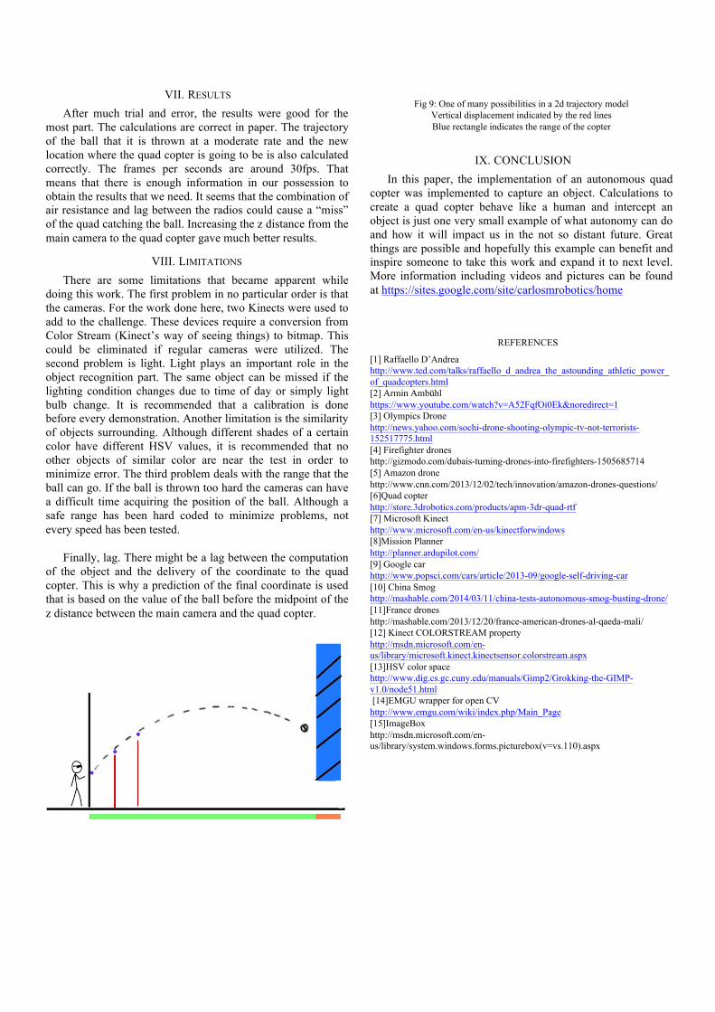
Fig. 5.above left (green ball detection in the given frame) Fig. 6.above right (green ball found, red box implies detection)
These values are essential and they need to be as accurate as possible since they are used in combination with the threshold value to determine if the object that we are tracking is in the frame that is being grabbed from the camera. Most of the code to achieve this is done using emgu1 libraries for the C# language.
Fig.7. (Six sliders, two for each HSV upper and lower limit values)
B. Threshold values
These values can be tweaked and they are based on the HSV values of the object that is going to be tracked. At the beginning of the program, the user can see a rectangle showing the object being tracked after the values have been stored. This rectangle only shows if the threshold value satisfies the range (set up distance value for the object). C. Coordinates
The coordinates of the objects are represented in XYZ values. Two of the values (X and Y) are given by the first camera. The third value (Z) is given by the second camera (its own X value). The example of a top view (2nd camera is shown on fig 8. For the first test only the X and Y value are used since the ball is rolled on the table. For the second test all three values are used. These values are in relation to the size of the ImageBox [15] used in C#. The real values have to be calculated based on the distance of the camera in relation to the ball and the quad copter. These values will also vary depending on the distance of the quad from the person.
The calculation sampled in this work is as follows. New
images are being processed every single time that the event raises. The image is checked to see if the object is detected. If it is then an XYZ coordinate is saved. Then on the next event a second XYZ is taken. If the second X value is not closer to the copter, the values are cleared and the process starts over. If the X value is closer to the copter then it continues with the rest of the algorithm to create the new XYZ coordinate where it thinks the ball will go.
An example of the many possible trajectories is shown on fig 9. The blue stripped rectangle represents the area of the copter. The red vertical rectangles show the vertical displacement at two different time intervals. The known values are the two location of the ball at, t1(x1, y1) and t2(x2, y2).
Fig.8. showing second camera top view with same coordinates
The t value is in seconds. The first two things that are calculated are the initial vertical velocity and the initial horizontal velocity. The formulas used to calculate these two values are:
Vx = x/t (1) Vy = (y/t) – 0.5*g*t (2)
The values of x and y are given at time t. The same x and y are used for both “(1)” and “(2)”.
Finally for the variable g, -9.8m per second is used because is low gravity and the negative sign is due to force bringing the ball down. The next calculation involves getting the horizontal displacement at various intervals. Doing the first eight seconds is more than enough since the total distance for this demo is about 3 meters. This can be changed if more distance is needed but the formulas stay the same.
While calculating all eight seconds, the program looks for
the t that gets within 0.25 (1foot) meters from the copter. If it finds one then it does the calculation for that particular t to find the vertical displacement. These two numbers are used to determine if the ball is reachable and that takes care of the two dimensional side of the side camera. The top camera takes care of the Z value. This value is simply created using the distance formula. dx = t2x – t1x (3) dy = t2y – t1y (4) Do the square of the distance between dx and dy: (dx2 + dy2) * k2 = tfinal (h) (5) Solve for k then get the final point: x3 = x1 + t1x + dx*k (6) y3 = x1 + t1y + dy*k (7) Since t1 and t2 have been recorded, the t1 and t2 Z values were recorded as well. For “(3)” and “(4)” these values are used. For “(5)”, the t final is used to calculate the “k” value and using that “k”, “(6)” and “(7)” are calculated and the final Z value is obtained. Remember that the same final t value that was previously used on the horizontal displacement is what is used to determine the final Z value. Keep in mind that instead of worrying if the ball will reach the copter, the program could have been done differently and the horizontal range could had been extended to further cover more ground and increase the potential of catching the ball. Approaching it in this manner would have had required a little bit of more testing. Once this is all calculated, a new location is created for the quad copter and the signal is sent for it to move to intercept the ball. The prototype catcher is shown on fig 4.
VII. RESULTS After much trial and error, the results were good for the
most part. The calculations are correct in paper. The trajectory of the ball that it is thrown at a moderate rate and the new location where the quad copter is going to be is also calculated correctly. The frames per seconds are around 30fps. That means that there is enough information in our possession to obtain the results that we need. It seems that the combination of air resistance and lag between the radios could cause a “miss” of the quad catching the ball. Increasing the z distance from the main camera to the quad copter gave much better results.
VIII. LIMITATIONS There are some limitations that became apparent while
doing this work. The first problem in no particular order is that the cameras. For the work done here, two Kinects were used to add to the challenge. These devices require a conversion from Color Stream (Kinect’s way of seeing things) to bitmap. This could be eliminated if regular cameras were utilized. The second problem is light. Light plays an important role in the object recognition part. The same object can be missed if the lighting condition changes due to time of day or simply light bulb change. It is recommended that a calibration is done before every demonstration. Another limitation is the similarity of objects surrounding. Although different shades of a certain color have different HSV values, it is recommended that no other objects of similar color are near the test in order to minimize error. The third problem deals with the range that the ball can go. If the ball is thrown too hard the cameras can have a difficult time acquiring the position of the ball. Although a safe range has been hard coded to minimize problems, not every speed has been tested.
Finally, lag. There might be a lag between the computation
of the object and the delivery of the coordinate to the quad copter. This is why a prediction of the final coordinate is used that is based on the value of the ball before the midpoint of the z distance between the main camera and the quad copter.
Fig 9: One of many possibilities in a 2d trajectory model Vertical displacement indicated by the red lines Blue rectangle indicates the range of the copter
IX. CONCLUSION In this paper, the implementation of an autonomous quad
copter was implemented to capture an object. Calculations to create a quad copter behave like a human and intercept an object is just one very small example of what autonomy can do and how it will impact us in the not so distant future. Great things are possible and hopefully this example can benefit and inspire someone to take this work and expand it to next level. More information including videos and pictures can be found at https://sites.google.com/site/carlosmrobotics/home
REFERENCES [1] Raffaello D’Andrea http://www.ted.com/talks/raffaello_d_andrea_the_astounding_athletic_power_of_quadcopters.html [2] Armin Ambühl https://www.youtube.com/watch?v=A52FqfOi0Ek&noredirect=1 [3] Olympics Drone http://news.yahoo.com/sochi-drone-shooting-olympic-tv-not-terrorists-152517775.html [4] Firefighter drones http://gizmodo.com/dubais-turning-drones-into-firefighters-1505685714 [5] Amazon drone http://www.cnn.com/2013/12/02/tech/innovation/amazon-drones-questions/ [6]Quad copter http://store.3drobotics.com/products/apm-3dr-quad-rtf [7] Microsoft Kinect http://www.microsoft.com/en-us/kinectforwindows [8]Mission Planner http://planner.ardupilot.com/ [9] Google car http://www.popsci.com/cars/article/2013-09/google-self-driving-car [10] China Smog http://mashable.com/2014/03/11/china-tests-autonomous-smog-busting-drone/ [11]France drones http://mashable.com/2013/12/20/france-american-drones-al-qaeda-mali/ [12] Kinect COLORSTREAM property http://msdn.microsoft.com/en-us/library/microsoft.kinect.kinectsensor.colorstream.aspx [13]HSV color space http://www.dig.cs.gc.cuny.edu/manuals/Gimp2/Grokking-the-GIMP-v1.0/node51.html [14]EMGU wrapper for open CV http://www.emgu.com/wiki/index.php/Main_Page [15]ImageBox http://msdn.microsoft.com/en-us/library/system.windows.forms.picturebox(v=vs.110).aspx