24
ASEPTIC SYSTEM User Manual DON’T GAMBLE WITH YOUR SAMPLE™

KEOFITT ASEPTIC SYSTEM USER MANUAL V.1 PAGE 1
ASEPTIC SYSTEMUser Manual
DON’T GAMBLE WITH YOUR SAMPLE™

KEOFITT ASEPTIC SYSTEM USER MANUAL V.1 PAGE 2
DOCUMENT VERSION LOGThe table below lists previous versions of this User Manual and states the major changes between ver-sions.This version list is introduced in April 2020.
Version # Version date Major changes from previous versions1 April 2020 Latest version without log

KEOFITT ASEPTIC SYSTEM USER MANUAL V.1 PAGE 3
INTRODUCTION: MANUFACTURER: KeofittA/S Kullinggade 31 B+E 5700 Svendborg, Denmark TYPE: ASEPTIC SAMPLING SYSTEM YEAR OF INTRODUCTION: 2020 YEAR OF REVISED DESIGN: 2020 MANUAL LAST UPDATED: April 2020
The English version of this Manual is the governing version and it is the only authorized version. Consequently, KEOFITT cannot be held liable for other versions including translations of this Manual.

KEOFITT ASEPTIC SYSTEM USER MANUAL V.1 PAGE 4

KEOFITT ASEPTIC SYSTEM USER MANUAL V.1 PAGE 5
CONTENTS1. PRESENTATION .................................................................................................................... 6
1.1Definitionofterms ..............................................................................................................................61.2 Quick start ...........................................................................................................................................8
2. CLEANING – DISINFECTION – STERILIZATION ........................................................................... 92.1 Clean-In-Place (CIP) ............................................................................................................................92.2 Disinfection ..........................................................................................................................................92.3 Sterilization .......................................................................................................................................10
3. DESCRIPTION OF THE ASEPTIC SAMPLING SYSTEM ................................................................ 123.1Valveheadconfigurations ................................................................................................................133.2 Membrane ..........................................................................................................................................133.3 Pressure Relief Valve .........................................................................................................................133.4Sterilefilter ........................................................................................................................................143.5 Parts and Accessories ........................................................................................................................14
4. EVERYDAY USE OF THE ASEPTIC SYSTEM ............................................................................... 154.1 Pre-sampling treatment ...................................................................................................................154.2 Connections .......................................................................................................................................154.3 Steaming ............................................................................................................................................16
5. ASEPTIC SYSTEM OPERATING INSTRUCTIONS ........................................................................ 175.1 Sampling valve preparations ...........................................................................................................175.2 Cleaning the Aseptic Sampling System ...........................................................................................175.3 Reassembling and autoclaving the Aseptic System .......................................................................185.4 Connecting the Aseptic System ........................................................................................................185.5 Steam sterilization ............................................................................................................................185.6 Sampling ...........................................................................................................................................195.7 Retrieving the sample ......................................................................................................................20
6. TECHNICAL DATA ................................................................................................................ 216.1 Material ..............................................................................................................................................216.2Certificate ..........................................................................................................................................216.3 Pressure (max.) ..................................................................................................................................216.4 Temperature ......................................................................................................................................216.5Surfacefinish .....................................................................................................................................216.6 Viscosity .............................................................................................................................................22
7. MAINTENANCE .................................................................................................................... 237.1 Maintenance ......................................................................................................................................237.2 Spare parts list ..................................................................................................................................237.3 Replacing a PTFE membrane ...........................................................................................................23

KEOFITT ASEPTIC SYSTEM USER MANUAL V.1 PAGE 6
1. PRESENTATIONThismanualdescribestheKeofittAsepticSamplingSystem.
The Keofitt Aseptic Sampling System enables the user to take a truly representative sterile sample. The Aseptic Sampling System protects the sample against airborne contamination, while taking the sample and during transfer to the laboratory. TheKeofittAsepticSamplingSystemisbasedonKeofitt’sguarantiedhighquality,microbiologicallysafevalvedesign.ThecurrentdesignisadoptedfromtheKeofittW9samplingvalve,whichis3-Aauthorized.The American 3-A Sanitary Standard is normative for the component’s ease of cleaning and sterilization and ensures optimum conditions for food products, which is in contact with the component in question. The Aseptic Sampling System is compatible with all medium (W9) sized Keofitt sampling valves. The Aseptic Sampling System is used in a wide range of processing industries, such as breweries, dairies,juice/softdrinksandthebiotechnologicalandpharmaceuticalindustries,whichallhavedifferent requirements and demands. VarioustestreportsandcertificatesaretobefoundontheKeofittwebsitewww.keofitt.dk.
1.1 Definition of termsIn order to ease the reading of this manual and to avoid any misunderstanding, please refer to the definitionoftermsinthetablebelow:
TERM DEFINITION
3-A Sanitary Standard, Inc. 3-A SSI is an independent, not-for-profit US corporation dedicatedto advancing hygienic equipment design for the food, beverage and pharmaceutical industries.
Acids An acid is a chemical substance whose aqueous solutions are characterized by a sour taste and the ability to react with bases and certain metals (like calcium) to form salts. Aqueous solutions of acids have a pH of less than 7. A lower pH means a higher acidity, and thus a higher concentration of positive hydrogen ions in the solution. Removes limestone and most mineral deposits.
Alkali Alkalis are all bases, which form hydroxide ions (OH-) when dissolved in water. The terms “base” and “alkali” are often used interchangeably. Alkalis have a pH value above 7. Alkalis dissolves fat and oil, destroys protein and attacks light metal.
Aseptic sampling The process of withdrawing a sample from the production equipment through a closed circuit, which has been sterilized and kept sterile with no exposure to the surroundings during the sampling process.
Bio load See Microbial load.Bioburden See Microbial load.Chemical Sterilant A few disinfectants will kill spores with prolonged exposure times (3–
12 hours); these are called chemical sterilants.Chlorine Chlorine is a chemical element with symbol Cl and atomic number
17. It belongs to the halogen group together with for instance iodine. It is a strong oxidizing agent and reacts with many substances. These propertiesmakechlorinecompoundsefficientdisinfectants.

KEOFITT ASEPTIC SYSTEM USER MANUAL V.1 PAGE 7
CIP Abbreviation of Clean-In-Place. The process of cleaning a process component (like a sampling valve) without removing it from the production line.
Cleaning Removal, usually with detergent and water or enzyme cleaner and water, of adherent visible soil on a surface.
Complexing agent A substance capable of forming a complex compound with another material in solution. Improves the cleaning properties of a detergent.
Contact time The time span during which the item is in contact with the detergent or the disinfectant.
Enzymes Molecules, which are added to cleaning agents to ease the removal ofspecificorganicmaterial.Assuressamecleaningeffectatalowertemperature.
Disinfectant Usually a chemical agent that destroys harmful microorganisms but might not kill bacterial spores.
Disinfection Thermal or chemical destruction of microorganisms. Disinfection is less lethal than sterilization, because it destroys most recognized microorganisms but not necessarily all microbial forms (e.g. bacterial spores).
Detergent A cleaning agent that has no antimicrobial effect, but in diluted solutions good cleaning properties.
EHEDG Abbreviation for the European Hygiene Engineering and Design Group. EHEDG is a consortium of equipment manufacturers, food industries, research institutes as well as public health authorities promoting safe food by improving hygienic engineering and design in all aspects of food manufacture.
Electro polishing Electro polishing is an electrochemical process by which the high points within the microscopic surface texture are removed and the corners rounded. This results in Reduced Product Adhesion, Ease of Cleaning and Improved Corrosion Resistance.
Exposure time Period in a sterilization/disinfectionprocess duringwhich the itemis exposed to the sterilant/disinfectant at the specific sterilization/ disinfection parameters.
Flow path Thepaththesampleflowsfromthetankorprocessequipmenttothesample recipient.
Germicidal The property of an agent to destroy microorganisms.Microbial load The number and types of viable microorganisms with which an item
is contaminated; also called bio load or bioburden.Microorganisms Animals or plants of microscopic size. As used in food and
pharmaceutical industries, generally refers to bacteria, fungi, viruses and bacterial spores.
Peracetic acid Acommonlyuseddisinfectant,whichisefficientatlowtemperatureand short contact time. Relatively harmless as it decomposes into carbon dioxide (CO2) and water (H2O).
Process media The product in the process equipment and the product from which a sample is taken.
Representative sample A sample which when it reaches the laboratory is still identical to the process media. A sample which is in no way contaminated or altered during neither the sampling process nor the transport to the laboratory.

KEOFITT ASEPTIC SYSTEM USER MANUAL V.1 PAGE 8
Sanitization The application of a chemical agent that reduces the number of bacterial contaminants to a safe level as judged by the public health authorities.Theofficialsanitizerprotocol indicatesthat99.999%ofthespecifictestbacteriabekilledin30secondsundertheconditionsof the test.
SIP Abbreviation for Sterilize-In-Place. The process of rendering a process component (like a sampling valve) sterile without removing it from the production line.
Spores Relatively water-poor resting cells surrounded by an impervious cell wall, which makes them relatively resistant to disinfectants and sterilants. They are dangerous as they can survive in adverse conditions and re-emerge as live bacteria at a later stage.
Sporicidal The property of an agent that kills spores.Steaming The process of using saturated steam under pressure as the sterilizing
agent.Sterile State of being free from all living microorganisms. In practice,
usually described as a probability function, e.g., as the probability of any microorganism surviving sterilization being one in one million.
Sterilant A few disinfectants will kill spores with prolonged exposure times (3–12 hours); these are called chemical sterilants.
Sterilization Validated process used to render an item free of all forms of viable microorganisms. In a sterilization process, the presence of micro- organisms is expressed in terms of probability. Although this probability can be reduced to a very low number, it can never be reduced to zero.
Sterility Assurance Level The probability of a viable microorganism being present on an item aftersterilization.Usuallyexpressedas10–n;aSALof10-6means<1/1,000,000chancethatasingleviablemicroorganismispresentona sterilized item.
Tensides A tenside is a surfactant that reduces the surface tension of water and assures a faster and better contact between the detergent and the soil.
1.2 Quick start The table below gives you an overview of the relevant chapters to read depending on the operations you want to perform to obtain the required hygienic level.
Required hygienic level
4.3
Stea
min
g
5.2
Clea
ning
the
As
epti
c Sa
mpl
ing
Sy
stem
5.3
Reas
sem
blin
g
and
auto
clav
ing
the
Asep
tic
Sam
plin
g
Syst
em
5.5
Stea
m
ster
iliza
tion
5.6
Sam
plin
g
Cleaning
Disinfection
Sterilization

KEOFITT ASEPTIC SYSTEM USER MANUAL V.1 PAGE 9
2. CLEANING – DISINFECTION – STERILIZATIONThis chapter gives introduction to the concepts of cleaning, disinfecting and sterilizing processequipment in general.
2.1 Clean-In-Place (CIP)Thorough cleaning of the Aseptic Sampling System is a prerequisite for proper disinfection. Cleaning of the valve is the removal of any visible residual product; it be organic or inorganic.Cleaning is the removal of adhering soil from the environment and from the previous sample (to the extent it has not been removed by the recommended post-sample cleaning). Cleaning is usually performed by flushingwithwaterfollowedbyathoroughwashingwithanappropriatedetergentandfinishedoffwitha thorough rinsing with water.Depending on the actual process media the proper detergent must be determined in cooperation with your usual supplier of detergents. The company Novadan ApS, Kolding, Denmark - www.novadan.dk, has supplied the generic table below for your convenience.
What to clean for Generic cleaning agents Comments
Fat Alkali and Tensides. Heat will facilitate the cleaning process as the fat melts.
Protein Alkali, Acids, Tensides and Chlorine. Coagulation and burning when heated, which makes the product hard to remove.
Sugar, Salt Water is usually sufficient as theproduct is water soluble.
Sugar caramelizes when heated, turning into a hard-sticky substance, which is difficulttoremove.
Minerals Acids, Complexing agent. Oftenseenaslimescale.Biofilm Alkali and Chlorine, Peracetic acid,
possibly Enzymes.Biofilm is an accumulated mass of micro- organisms that is tightly adhered to a surface and cannot be easily removed.
Starch Alkali and Chlorine.
2.2 DisinfectionAlthough CIP removes all visible residues of the process media the valve surfaces will still be contaminated on a microscopic level. Depending on your actual process media it will be necessary to carry out a disinfection operation in order to a) reduce the microbial load to an acceptable level (also referred to as Sanitization) or b) destroy critical microorganisms, but not necessarily all microbial forms (e.g. bacterial spores). DisinfectionoftheAsepticSamplingSystemissplitinto2operations:
• Initial autoclaving of the system components.• Steaming of the flow path of the system together with the sampling valve on the process
equipment just prior to taking the sample.Using a liquid chemical disinfectant is generally a valid alternative to steaming an ordinary sampling valve on a process line. However, to take an aseptic sample using the Aseptic Sampling System steaming is generally the preferred method (see explanation in chapter 2.3 Sterilization).There are several chemical disinfectants. It is important to choose the right one, the right concentration and contact time and the right method for your current application. Your usual supplier of chemical disinfectantscansupportyouinchoosingtherightdisinfectantforyourprocessmediaandthespecificgroup of microorganisms you are aiming at.

KEOFITT ASEPTIC SYSTEM USER MANUAL V.1 PAGE 10
The company Novadan ApS, Kolding, Denmark has supplied the table below, as a preliminary indication ofwhichtypeofdisinfectanttouse:
Disinfectant
Microbes to inactivate
Halogens(Chlorine)
Peroxides(Hydrogen peroxide
&Peracetic acid)
Alcohol(70%)
Gram-negative bacteriaSalmonellaCampylobacterE. Coli and others...
Gram-positive bacteriaListeriaBacillus cereusClostridium and others...
Bacteria spores Bacillus cereus and others...
BacteriophageYeastFungiVirus
Legend: Efficient Limitedeffect Little/Noeffect
NOTE! The final choice of detergent, disinfectant and method lies with the user, supportedbythesupplieroftheCIPfluidsanddisinfectants,asitisverymuchdependentonindividual concerns and circumstances.
2.3 SterilizationSterilization is a high-level disinfection designed to render the valve free of all forms of viable microorganisms (incl. bacterial spores) to a high level of certainty; the so-called Sterility Assurance Level or SAL. A SAL value of 10-6 means that the probability (or risk) of a single viable microorganism being presentontheequipment interiorafterwards isonly1 in1,000,000which isagenerallyaccepted levelfor calling an item sterile. Although the probability can be reduced to a very low number, it can never be reduced to zero.Sterility may in practice only be obtained by steaming. Disinfectants exist that in high concentrations and for a prolonged exposure time will be able to inactivate all forms of microorganisms and render the equipment interior sterile with a high probability; these disinfectants are called chemical sterilants. However, the application of chemical sterilants is most often problematic due to a) a required high concentration, which causes an operator hazard and b) the several hours of exposure time.
NOTE! Furthermore, sterilization with a chemical sterilant may not convey the same sterility assurance as sterilization with steam, because the germicidal and sporicidal kinetics are much less investigated and documented for chemical sterilants compared to steam.

KEOFITT ASEPTIC SYSTEM USER MANUAL V.1 PAGE 11
WARNING!
• During sterilization with steam the valve will become hot and care should thus be taken when operating the valve.
• When steaming always use dry saturated steam without condensation at max. 1 bar(g). At higher pressurethemembranemaybedamaged/split.
• Always remember to use safety goggles when steaming, taking samples and all other operations of the sampling valve.

KEOFITT ASEPTIC SYSTEM USER MANUAL V.1 PAGE 12
3. DESCRIPTION OF THE ASEPTIC SAMPLING SYSTEM TheAsepticSamplingSystem(hereaftercalledAsepticSystemorjustSystem)ismeanttoregularlytakesterile representative samples from the production process into a plastic bottle. The Aseptic System is therefore designed so that effective cleaning, sterilization and sampling can be carried out regularly without interrupting the production process.
TheAsepticSystemconsistsof:• Asystembodywithinlet,airoutletthroughsterilefilterandsteamoutletwithapressurerelief
valve.• A valve head with a lever actuator (type Q with PTFE membrane).• An integrated screw cap (disconnectable).• A handle with a rubber cover.
Available accessories see chapter 3.5.
Valve Head(TypeQw/PTFEmembrane)Sterile Filter
Handle
Inlet
Outlet
Pressure Relief Valve
Screw cap for PP Bottle

KEOFITT ASEPTIC SYSTEM USER MANUAL V.1 PAGE 13
The Aseptic System’s inlet port is connected to the output port of the production line sampling valve using aPTFEtubing.Supplyingsteamthroughtheconnectedpartscarriesoutsterilizationoftheentireflowpath.WiththeSysteminitsuprightpositionitisautodrainable,suchthataftersteaminganycondensatewillflowoutofthesystembody.
The Keofitt Aseptic System is based on the acknowledged Keofitt valve design. Steaming does flush, cleaning, rinsing and sterilization in one operation. Steaming is therefore a SIP process (Sterilize-In-Place).
AftersterilizationandshuttingoffthesteamsupplytheAsepticSystem’svalveisopenedusingtheleverhandleallowingaflowpathintothesamplebottle.Subsequentlyopeningofthesamplingvalvewillcauseproductmediafromtheprocesstoflowintothesamplebottlethroughthesterilizedflowpath.Productflowing to thebottlecauses thatair fromthebottlewillbeexpelled throughtheairoutlet,where the sterilefilterismounted.Tomaintainasepticconditionsasterilefiltermustbeconnectedtotheairoutletprior to autoclaving the system. When the required sample volume is obtained, the sampling valve at production line and the valve in theAsepticSystemmustbeclosedandsteamcouldbeadministeredtorinsetheflowpath.TheAsepticSystem now contains a sterile sample of the media in the production line and may be safely carried to the laboratory for analysis.
WARNING!• During sterilization with steam the sampling valve and the Aseptic System will become hot and
care should thus be taken when operating the valves.• When steaming always use dry saturated steam without condensation at max. 1 bar(g).• In case of obstruction of the air outlet pressure will build up in the bottle eventually causing it toburstiffilledwithliquid.Tohelpavoidingtoohighpressure,areliefvalveismountedattheoutlet of the Aseptic System. The relief valve will gradually open when pressure reaches 2-3 bar in the Aseptic System.
• Always remember to use safety goggles when steaming and taking samples and during all other operations of the sampling valve and the Aseptic System.
3.1 Valve head configurationsValveheadscomeinthefollowingconfigurations:
• Lever handle (type Q) AllconfigurationscomewithW9TM-membrane PTFE.
3.2 MembraneThe valve head is delivered with PTFE membrane.The PTFE membrane resists all CIP fluids and disinfectants except highly oxidizing acids in high concentrations.Forfurtherinformation,pleaserefertospecificDatasheetforarticlenumber850055.
3.3 Pressure Relief ValveThe Aseptic System comes with a spring actuated relief valve, which is designed to open at approximately 2-3 bar. The relief valve serves two functions as it is both a closeable outlet for steam and cleaning media (maintain aseptic conditions in the Aseptic System while taking sample) as well as function as relief valve for high pressure build up in the System due to wrong handling.
The relief valve has a plastic turn knob to manually open and close, as it also serves as outlet when
Valve Head(TypeQw/PTFEmembrane)

KEOFITT ASEPTIC SYSTEM USER MANUAL V.1 PAGE 14
cleaning the aseptic system. When cleaning the Aseptic System, the relief valve must be in its open position to let out cleaning media or steam. When in sampling mode, the relief valve must be in closed position. If a pressure of approx. 2-3 bar is build up in the system, the valve will gradually open and lead out excess air or product sample. At normal sampling procedure, the relief valve will stay in its closed position. If, at some reason the pressure in the system increase to 2-3 bar, e.g. the air outlet is blocked, the relief valve will gradually open and lead out excess air and liquid. When pressure decrease to approximately 0.5 bar, the valve will return to closed position.
3.4 Sterile filterTheAseptic systemcomeswithaWhatman™Puradisc™25TFfilter,poresize0.2µm.Thefiltercanbemounteddirectly in theairoutletof theAsepticSystemvia thefilters luerconnectionorbeplaced inthequickcouplinghousing forbetterfixation.For further informationon thefilter,please refer to the Datasheet article number 260122 or alternatively www.whatman.com.
3.5 Parts and AccessoriesKeofittprovideahugenumberofsparepartsandaccessoriestotheentirerangeofsamplingvalves.Theseincludesparepartslike:
• Membranes • O-rings and gaskets• Bushings• Handles
andotheraccessorieslike:• Barbedfittingsandtubeweldingfittingsfortubesandhoses• Adaptors between Tri-clamp, Mini Tri-clamp and Hose Piece (Quick Coupling)• Fitted PTFE tubing for Quick Coupling and Tri-clamp• Any length of PTFE tube• Clamps for Tri-clamp connections• Click-on steamer• Circulator• Sampling bottle systems

KEOFITT ASEPTIC SYSTEM USER MANUAL V.1 PAGE 15
4. EVERYDAY USE OF THE ASEPTIC SYSTEMThischapterintroducesthedifferentworkingstepswhenusingtheAsepticSystem.Forspecificoperatorinstructions please refer to chapter 5. ASEPTIC SYSTEM OPERATING INSTRUCTIONS.
NOTE! For specific instructions on operating the sampling valve on your production line,please read the corresponding user manual carefully.
4.1 Pre-sampling treatment The Aseptic System is a re-usable system, which must be cleaned and autoclaved prior to each use. The sampling valve on the production line must be prepared for taking samples according to the instructions in its user manual.
4.2 ConnectionsTheSystem’sdifferentconnectionsareseenontheillustrationbelow.
Thesteaminletofthesamplingvalveisconnectedtoasteamsupplyfeaturingashut-offvalvetocutthesteamsupplyaftersterilization.The outlet port of the sampling valve is connected to the inlet port of the Aseptic System via a PTFE tube (accessory).
Valve Head(TypeQw/PTFEmembrane)Sterile Filter
Handle
Inlet
Outlet
Pressure Relief Valve
Screw cap for PP Bottle
KEOFITT ASEPTIC SYSTEM USER MANUAL V.1 PAGE 16
The Aseptic System’s Steam Outlet port is connected to drain or similar, taking care to avoid getting injuredbythesteamjet.Usingasteamtrapisnotrecommendedhere,asitwillimpedetheflowofsteamandthustheflushingeffect.The Aseptic System’s Air Outlet connects to the interior of the bottle and allows air to be expelled as the sampleliquidfillsthebottle.Inordertomaintaintheasepticenvironmentinthesystem,theairoutletisfittedwitha0.2µmporefilter(seesection.3.4).Itispossibletousebothreusableandsingleusefiltersforthis purpose, please see the table below for comparison.
Solution Description Comments
1. Sterile venting filter(replaceable/reusable)
They are either a) a stainless-steel housing with replaceable filter in-serts or b) sealed plastic filters,which can be autoclaved many times.
For both types it is critical to discard the filtersregularlytoavoidusingablockedfilter,whichmayleadtoseriouspressurebuild-up in the sample bottle causing it to blast.
2. Sterile venting filter(single use)
Small disc shaped plastic filterswith hose barb, luer lock or similar connections.
Acostefficientsingle-usesolution,whichmay be autoclaved together with the Aseptic System.
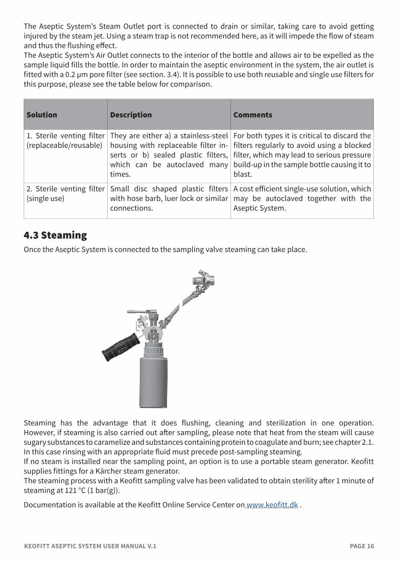
4.3 SteamingOnce the Aseptic System is connected to the sampling valve steaming can take place.
Steaming has the advantage that it does flushing, cleaning and sterilization in one operation. However,ifsteamingisalsocarriedoutaftersampling,pleasenotethatheatfromthesteamwillcause sugary substances to caramelize and substances containing protein to coagulate and burn; see chapter 2.1. Inthiscaserinsingwithanappropriatefluidmustprecedepost-samplingsteaming.Ifnosteamisinstallednearthesamplingpoint,anoptionistouseaportablesteamgenerator.KeofittsuppliesfittingsforaKärchersteamgenerator.ThesteamingprocesswithaKeofittsamplingvalvehasbeenvalidatedtoobtainsterilityafter1minuteofsteaming at 121 °C (1 bar(g)).
DocumentationisavailableattheKeofittOnlineServiceCenteronwww.keofitt.dk .

KEOFITT ASEPTIC SYSTEM USER MANUAL V.1 PAGE 17
5. ASEPTIC SYSTEM OPERATING INSTRUCTIONSThis chapter provides clear instructions on how to operate the Aseptic System. Before sampling the sampling valve and the Aseptic System must be prepared for the sampling process.
5.1 Sampling valve preparations Ifthesamplingvalvehasbeencleanedproperlyafterthelastsampling,theremightbenoneedforanyaction before steaming. Otherwisethesamplingvalveshouldbecleaned/disinfected/steamedaccordingtotheinstructionsinthesampling valve user manual. Final sterilization is done when the Aseptic System is connected (see chapter 5.4 and 5.5).
WARNING!• Carefully follow the guidelines given for any chemicals involved in the cleaning process.• Always remember to use safety goggles when steaming, cleaning, taking samples and all other
operations of the sampling valve.
5.2 Cleaning the Aseptic Sampling System CleaningtheAsepticSystemandpreparingitforthenextsamplingismostefficientlydoneimmediatelyaftertheprevioussamplehasbeenemptiedoutofthebottle.TocleantheAsepticSystemproperlyitmustbe disassembled.
NOTE! The screw cap may also be disconnected from the Aseptic System body for proper cleaning of the screw cap interior and the internal retention nut.
TodismantletheAsepticSystem(includingthescrewcap)performthefollowingoperations:1. Disconnectreliefvalve,filter,alltubingandhoses.2. Fasten the bottle tight onto the screw cap. 3. Holding the system by the housing and by the screw cap respectively, now unscrew, thereby
unscrewingthesteelcapflange,thescrewcapandthebottleasoneassembly.4. Dismantle this assembly taking care not to lose the O-ring and the gasket. 5. Open the valve using the lever handle. 6. Unscrew the valve head and remove it from the system body. 7. Wash the valve head, system body, relief valve, bottle, hoses and all other parts having been used
for sampling.8. Rinse and dry all parts.
TodismantletheAsepticSystemleavingthescrewcapinplaceperformthefollowingoperations:1. Disconnectreliefvalve,filter,alltubingandhoses.2. Holding the system housing and the screw cap together, now unscrew the bottle, making sure
thebottleflangeisnotloosened.3. Remove the clear gasket. 4. Open the valve using the lever handle. 5. Unscrew the valve head and remove it from the system body. 6. Wash the valve head, system body, relief valve, bottle, hoses and all other parts having been used
for sampling.7. Rinse and dry all parts.

KEOFITT ASEPTIC SYSTEM USER MANUAL V.1 PAGE 18
WARNING!• Carefully follow the guidelines given for the chemicals involved.• Always remember to use safety goggles when steaming, cleaning, taking samples and all other
operations of the sampling valve.
5.3 Reassembling and autoclaving the Aseptic System AfterpropercleaningtheSystemmustbereassembledandautoclaved,followingthesesteps:
1. Screw the valve head on the system body making sure the valve head is in its open position (to avoid damaging the membrane).
2. Leave the valve in its open position.3. Add a few drops of clean water to the bottle. 4. Screw the bottle on to the cap.5. Loosen the bottle half a turn to allow heat to access the interior of the bottle. 6. Addthefiltertotheairoutlet.7. Add relief valve, any tubing, hoses and other items that must be autoclaved (these items may be
placed in sterilizable bags for further protection until use).8. Autoclave the assembly.
Afterautoclavingperformthefollowingsteps:1. Immediatelyafteropeningtheautoclavescrewthebottlefirmlyontothecap.2. Immediatelythereafterclosethevalve.3. Immediatelythereafterfitanyhoses.4. Take out the assembly and other parts from the autoclave
Having done 1 and 2 you now have a sealed bottle unit, which is sterile on the inside.
5.4 Connecting the Aseptic SystemAfter having autoclaved the Aseptic System take it and its accessories to the sampling point in the production. Havingpreparedthesamplingvalveaccordingtochapter5.1performthefollowingsteps:
1. Using a PTFE hose, connect the sampling valve’s lower outlet port to the inlet port of the Aseptic System.
2. Connect a hose to the Aseptic System’s Steam Outlet and let it go to drain or some appropriate collectorofsteam(don’tuseasteamtrapwhichwilllimittheflowofsteamandgreatlyreducetheflushingeffectofthesteamjet).
5.5 Steam sterilization Steam sterilization of the flow path takes place with both the sampling valve and the system valve remainingintheirclosedpositionsandreliefvalveinitsopenposition.Performthefollowingsteps:
1. Make sure the steam supply is connected to the sampling valve’s upper inlet port. 2. Openthesteamsupplyandlet itflowthroughthesamplingvalveandtheAsepticSystemfor
sterilization. Allow minimum 1 minute at 121 °C (1 bar(g)). 3. Close the steam supply but leave the hose in place to prevent contamination from the ambient
during sampling. If removalof the steamhose is required, immediatelyfita sterile rubberorstainless-steel plug onto the sampling valve’s upper connector.
4. Close relief valve by turning the knob clockwise.
Thevalveisnowreadytotakeasample.Thesamplingmustbeperformedimmediatelyaftersteamingto

KEOFITT ASEPTIC SYSTEM USER MANUAL V.1 PAGE 19
avoidanycontaminationoftheflowpath,thebottleandhencethesample.Iftheprocessmediaisheatsensitive,itmaybenecessarytowaitforthevalvestocooloff.
WARNING!• During sterilization with steam the System valve will become hot and care should thus be taken
when operating the valve. • Do not open the System valve while sterilizing with steam, as it would lead steam into the bottle. • For a System allowed under ATEX
both the handle and the top of valve head (type Q) must be cleaned before use.• Always remember to wear safety goggles when steaming, cleaning, taking samples or any other
operations of the sampling valve or the System valve.
IMPORTANT! • Don’tattachasteamtraptothehosefromtheSteamOutletasitwillimpedetheflowofsteamand hence the flushing effect, and make the sterilization dependent on temperature only, demanding a much longer sterilization time.
• If thesteamcapacity is lowand/or theoutlethose fromthevalve is longand/orwitha largediameter, the temperature will drop, and condensation may occur in the valve chamber. In this case a counter pressure must be established using the pressure relief valve at the System’s Steam Outlet.
• Leave the steam hose in place on the sampling valve to maintain the aseptic condition and prevent contamination from the ambient during sampling.
5.6 Sampling The Aseptic System is now ready to take a sterile sample in an aseptic environment. Take the sample immediatelyaftersterilization(andcoolingoff,ifrequired)performingthefollowingsteps:
1. Open the Aseptic System’s valve fully and leave it open. 2. Openthesamplingvalveslowlyuntilasuitableflowisobtained.3. Fill the bottle with the required volume of sample. 4. Shutthesamplingvalveafterthesamplehasbeentaken.5. Shut the Aseptic System’s valve. 6. Disconnect the hose from the Aseptic System’s inlet port. 7. Disconnect the hose from the relief valve from Aseptic System’s Steam Outlet port.8. Clean the sampling valve as appropriate following the instructions from its User Manual.
You now have a sterile sample in the bottle to take to the laboratory.
WARNING!• Whensamplingatahighpressureand/orwithalowviscosityprocessmediaitmayflowrapidly
into the sample recipient. Therefore, open the sampling valve slowly. Special care must be taken with pneumatically operated sampling valves, as they open abruptly.
• Always remember to wear safety goggles when steaming, cleaning, taking samples or any other operations of the sampling valve.

KEOFITT ASEPTIC SYSTEM USER MANUAL V.1 PAGE 20
5.7 Retrieving the sample AftersamplingtaketheAsepticSystemtothelaboratory.In a LAF bench unscrew the bottle from the System by holding on to the screw cap. The sample is now ready tobefilled into another containerorwhatever elsemightbeneeded for the analysis. After the Aseptic System has been emptied it must made ready for the next sample by performing the cleaning process (chapter 5.2) and the autoclaving (chapter 5.3).

KEOFITT ASEPTIC SYSTEM USER MANUAL V.1 PAGE 21
6. TECHNICAL DATA
6.1 MaterialSteelparts: AISI316L(1.4404)Membrane: PTFE(white)O-ring: EPDM(black)Screwcap: Polypropylene(PP)Sealingring: Thermoplasticelastomer(TPE)
6.2 CertificateAsepticsystem: 3.1*,RaCert.incl.measurements**
* A 6-digit code ismarked on the valve body. This code refers to a 3.1 certificatewhichaccompanieseveryconsignmentofvalvebodies.The3.1certificateisavailableattheKeofittOnlineServiceCenteronwww.keofitt.dk.ClickCertificatesandthen3.1.
**Thesurfaceroughnessismeasuredforeachasepticsystemat3criticalplaces. A serial number identifies each aseptic system. A specific surface roughnesscertificateforeachvalvebodyisavailableonwww.keofitt.dk
Membrane: PTFEacc.toFDA,EU10,EC1935,USP88ClassVI,EC2023
6.3 Pressure (max.)Inlet: Dependingofthevalvehead.
Normal operation is pressure less, as pressure drop is across the sampling valveandthesampleflowspredominantlybygravity.
6.4 TemperatureSteam: Sterilizationusingdry, saturated steamat 121 °C / 250 °F and 1 bar(g). Dry,saturatedsteamattemperaturesupto134°C/272°Fand2bar(g)is possible but might reduce the service life of the membrane.
Processmedium: The acceptable operating temperature range for the process medium dependsonthechoiceofmembraneasfollows: PTFE:0°Cto150°C(32-300°F)
Sub-zero Centigrade operation is possible with all membranes. Please consult your local distributor and KEOFITT if occasion arises.
Ambient: The range of acceptable ambient temperatures is limited by the polymer handle and the pneumatic cylinder from -40 °C to 80 °C.
6.5 Surface finishInternal: ElectropolishedRa≤0.8µm/31µinchExternal: ElectropolishedRa≤1.2µm/47µinch

KEOFITT ASEPTIC SYSTEM USER MANUAL V.1 PAGE 22
6.6 ViscosityViscosityrange: 0-1000cP,withparticlesuptoØ3mmindiameter.
Higher viscosity liquids may be sampled, only will the sampling take longer.

KEOFITT ASEPTIC SYSTEM USER MANUAL V.1 PAGE 23
7. MAINTENANCE7.1 MaintenanceThe membrane must be inspected between batches. PTFE membranes should be replaced every 12 months. In the event of intensive cleaning it may be necessary to replace it more frequently. The appropriate replacement frequency should be determined by the user by starting with short intervals and continuously extend the time in use until one reaches the limit of the membrane’s durability. Based on the desired safety margin the user then decides on the replacement interval to adapt.
7.2 Spare parts list 1. Spring 2. Steel bushing 3. Lower stem 4. Membrane PTFE (White)5. Valve body 6. Sealing ring 7. Screw cap
7.3 Replacing a PTFE membrane The description and illustrations below show a type N with lever handle, but the instructions also apply to other valve head types. Toremoveanoldmembranefromthevalvehead:
1. OPEN the valve (lever handle position as in illustration A). 2. Unscrew the valve head from the valve body. 3. CLOSE valve head (illustration A). 4. Pushthemembraneandbushingapart(illustrationB)untilthetoolformembranefitsunderit.5. Insert tool for membrane, between the membrane and the bushing (illustration B). 6. OPEN valve head (illustration C). 7. Now the membrane is loosened from the valve head and can be replaced.
Toattachanewmembranetothevalvehead:8. Set the valve head to CLOSED position (lever handle position as in illustration B). 9. Place the new membrane on valve head.
10. Mount the membrane bushing with the new PTFE membrane by pressing the tip of the
1
2
3
4
5
6
7

KEOFITT ASEPTIC SYSTEM USER MANUAL V.1 PAGE 24
membrane with your hand until it clicks. 11. Set the valve head in OPEN position (lever handle position as in illustration A). 12. Insert the valve head into the valve body. 13. CLOSE valve head.
IMPORTANT!• Once the membrane has been removed from the valve head the click system in the
membrane might be damaged. Therefore, the membrane might be unsafe for further use and it is recommended not to use the membrane again.
• Do not use hammer or other tool that might scratch the surface of the membrane.
A. B. C.


