Ash & Lacy Building Systems LtdBromford Lane West Bromwich West Midlands B70 7JJTel: 0121 525 1444 Fax: 0121 525 3444e-mail: [email protected]: www.ashandlacy.com
The BBA is a UKAS accredited certification body — Number 113. The schedule of the current scope of accreditation for product certification is available in pdf format via the UKAS link on the BBA website at www.bbacerts.co.uk
Readers are advised to check the validity and latest issue number of this Agrément Certificate by either referring to the BBA website or contacting the BBA direct.
ASH & LACY RAINSCREEN SYSTEMS
ASH & LACY BUILDING SYSTEMS ALUCOBOND FAÇADE CLADDING SYSTEMS
This Agrément Certificate Product Sheet(1) relates to Ash & Lacy Building Systems Alucobond(2) Façade Cladding Systems, comprising aluminium sheet composite panels attached to an aluminium sub-frame, used as a drained and back-ventilated rainscreen cladding system to provide a decorative and protective façade over external concrete, masonry, steel and timber frame walls of new and existing buildings.(1) Hereinafter referred to as ‘Certificate’.(2) Alucobond is a registered trademark of 3A Composites GmbH.
CERTIFICATION INCLUDES:• factors relating to compliance with Building
Regulations where applicable• factors relating to additional non-regulatory
information where applicable• independently verified technical specification• assessment criteria and technical investigations• design considerations• installation guidance• regular surveillance of production• formal three-yearly review.
KEY FACTORS ASSESSEDStrength and stability — the cladding systems can resist the surface loadings normally encountered in the UK and transfer the design loads to the substrate wall structure (see section 6).Behaviour in relation to fire — the cladding panels have various reaction-to-fire classifications (see section 7).Air and water penetration — provided all joints between panels are adequately baffled, the cladding systems will minimise water entering the cavity. Any water collecting in the cavity owing to rain and condensation will be removed by drainage and ventilation (see section 8).Durability — the cladding systems have acceptable durability and can be expected to have a service life of in excess of 30 years (see section 10).
The BBA has awarded this Certificate to the company named above for the systems described herein. These systems have been assessed by the BBA as being fit for their intended use provided they are installed, used and maintained as set out in this Certificate.
On behalf of the British Board of Agrément
Date of First issue: 12 October 2015 Brian Chamberlain Claire Curtis-Thomas
Head of Technical Excellence Chief Executive
Page 2 of 13
In the opinion of the BBA, Ash & Lacy Building Systems Alucobond Façade Cladding Systems, if installed, used and maintained in accordance with this Certificate, can satisfy or contribute to satisfying the relevant requirements of the following Building Regulations (the presence of a UK map indicates that the subject is related to the Building Regulations in the region or regions of the UK depicted):
The Building Regulations 2010 (England and Wales) (as amended)
Requirement: A1 Loading
Comment: The systems are acceptable for use and can be designed to adequately transfer the design loads from the cladding to the substrate wall structure as set out in sections 4.3 and 6.1 to 6.11 of this Certificate.
Requirement: B4(1) External fire spread
Comment: The panels are capable of achieving Class 0 requirements. See section 7 of this Certificate.Requirement: C2(b) Resistance to moisture
Comment: The systems will meet this requirement. See section 8 of this Certificate.Regulation: 7 Materials and workmanship
Comment: The systems are acceptable. See section 10 and the Installation part of this Certificate.
The Building (Scotland) Regulations 2004 (as amended)
Regulation: 8(1)(2) Durability, workmanship and fitness of materials
Comment: The systems are acceptable. See sections 9 and 10 and the Installation part of this Certificate.Regulation: 9 Building standards applicable to constructionStandard: 1.1(a)(b) Structure
Comment: The systems are acceptable with reference to clauses 1.1.1(1)(2). See sections 4.4 and 6.1 to 6.11 of this Certificate.
Standard: 2.4 Cavities
Comment: The panels, when used in conjunction with fire-resistant materials, can meet this Standard, with reference to clauses 2.4.1(1)(2), 2.4.2(1)(2), 2.4.5(1), 2.4.7(1)(2) and 2.4.9(2). See sections 4.3 and 7.8 of this Certificate.
Standard: 2.6 Spread to neighbouring buildings
Comment: The panels can contribute to a construction satisfying this Standard, with reference to clauses 2.6.4(1)(2), 2.6.5(1), 2.6.6(1)(2) and 2.6.7(2). See section 7 of this Certificate.
Standard: 2.7 Spread on external walls
Comment: The panels can contribute to satisfying this Standard, with reference to clause 2.7.1(1)(2). See sections 7.1 and 7.8 of this Certificate.
Standard: 3.10 Precipitation
Comment: The systems will contribute to meeting this Standard, with reference to clauses 3.10.1(1)(2), 3.10.3(1)(2), 3.10.5(1)(2) and 3.10.6(1)(2). See section 8 of this Certificate.
Standard: 7.1(a)(b) Statement of sustainability
Comment: The systems can contribute to meeting the relevant requirements of Regulation 9, Standards 1 to 6 and therefore will contribute to a construction meeting a bronze level of sustainability as defined in this Standard.
The Building Regulations (Northern Ireland) 2012 (as amended)
Regulation: 23 Fitness of materials and workmanship
Comment: The systems are acceptable. See section 10 and the Installation part of this Certificate.Regulation: 28(b) Resistance to moisture and weather
Comment: The systems will contribute to meeting this Regulation. See section 8 of this Certificate.Regulation: 30 Stability
Comment: The systems are acceptable as set out in sections 4.3 and 6.1 to 6.11 of this Certificate.Regulation: 36 External fire spread
Comment: The panels are capable of achieving Class 0 requirements. See section 7 of this Certificate.
Construction (Design and Management) Regulations 2015Construction (Design and Management) Regulations (Northern Ireland) 2007
Information in this Certificate may assist the client, Principal Designer/CDM co-ordinator, designer and contractors to address their obligations under these Regulations.See sections: 1 Description (1.2), and 3 Delivery, storage and site handling (3.5) of this Certificate.
Regulations
Page 3 of 13
Additional Information
NHBC Standards 2014NHBC accepts the use of Ash & Lacy Building Systems Alucobond Façade Cladding Systems, provided they are installed, used and maintained in accordance with this Certificate, in relation to NHBC Standards, Chapter 6.9 Curtain walling and cladding.
Technical Specification
1 DescriptionGeneral1.1 Ash & Lacy Building Systems Alucobond Façade Cladding Systems comprise Alucobond composite panels attached to an aluminium sub-frame secured to external walls.
Panels1.2 The panels are available in three grades and two styles (see Table 1) and consist of a core layer bonded either side to aluminium outer skins. The panels are available in various thicknesses and colours.
(1) Lengths up to 8000 mm available on request.(2) 1750 mm width available on request.(3) 1650 mm width available on request.
1.3 The panel outer skins consist of 0.5 mm thick aluminium sheets manufactured from aluminium alloys EN AW-5005 or EN AW-3003, EN AW-3005, EN AW 3105 as per BS EN 485-2 : 2013 (bare anodised) or BS EN 1396 : 2015 (coated) with properties shown in Table 2. The external face of one or both sides of the skin may be plain, anodised (20 μm thick), primed (for post paint finish), or pre-painted with either 25 μm minimum coating of polyester paint, or PVDF (polyvinylidene fluoride) protective coating.
Table 2 Aluminium sheet properties
Property Value
E modulus (E) (N∙mm–2) 70,000
Tensile strength (Rm) (N∙mm–2) 130
0.2% proof strength (Rp 0.2) (N∙mm–2) 90
Elongation at break (A50 mm) (%) 5
1.4 The panels may be used as flat panels or tray panels (ie folded flat panels produced in the factory by routing out the inner face and most of the core, down the length of a panel, and then bending to shape). Where necessary, the flat panels can be bent to form corner panels and trims for use around openings and installation perimeters. The panels can also be fabricated into bespoke shapes and profiles when required(1).(1) Outside the scope of this Certificate.
1.5 Flat panels are riveted around the perimeter to the vertical support rails and cross-member bracing (see Figure 1a). The vertical support rails are bolted to the wall brackets and fixed to the substrate.
Page 4 of 13
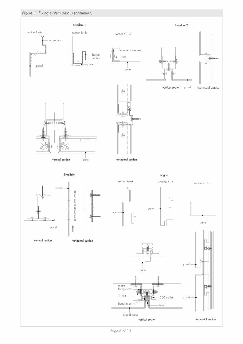
1.6 Fabricated cassette tray panels are either hung from vertical support rails using mounting bolts (see Figure 1b) or mechanically fixed to vertical support rails using rivets and fascia screws (see Figure 1c).
1.7 The panels are strengthened at the fixing points; tray panels incorporate corner sheet plates riveted to the side corners of the panel, and also include a continuous vertical section riveted to the tray side. In addition, horizontal aluminium reinforcing profiles fastened with rivets along the top and bottom of the tray panels for lateral stability may be required (see section 6).
Support system1.8 The panels are attached to the substrate via an aluminium sub-frame system comprising rail and wall brackets fixed to the substrate. The specifications of fasteners and support rails are given in Table 3.
Table 3 Fastener/rail system details
Type/system Description
Flat panel
Wall bracket Specified on project basis by a suitably-qualified and experienced individual
Vertical support rail and cross-member section Minimum 1.6 mm thick aluminium alloy 6000 series T- or L-shaped profile (eg EN AW 6060 or EN AW 6063 to BS EN 573-3 : 2013) mill finish or powder-coated
Rail/bracket fixing 5 mm diameter shank blind rivet (aluminium) or self-drilling screw minimum 4.8 mm diameter stainless steel (grade 1.4301 material)
Sub-frame rivet (cross member to rail) 6 mm diameter head with 3 mm diameter shank; aluminium with stainless steel mandrel
Rivets (panel to rail/cross member) 11 mm, 14 mm or 16 mm head diameter with 5 mm diameter shank; aluminium body with stainless steel mandrel or aluminium pop rivet with steel mandrel which pops out on application
Tray panel (mounting)
Wall bracket Specified on project basis by a suitably-qualified and experienced individual
Vertical support rail Minimum 1.6 mm aluminium alloy (6000 series) U profile (eg EN AW 6060 or EN AW 6063 to BS EN 573-3 : 2013) mill finish or powder-coated
Corner sheet (reinforcement) Minimum 2 mm thick aluminium alloy EN AW 5754
Rivets (corner sheet to panel) 11 mm, 14 mm or 16 mm head diameter with 5 mm diameter shank; aluminium body with stainless steel mandrel or aluminium pop rivet with steel mandrel which pops out on application
Bolt mountings 10 mm diameter stainless steel (grade 1.4301 material)
Tray panel (mechanically fastened)
Wall bracket Specified on project basis by a suitably-qualified and experienced individual
Vertical support rail Minimum 1.6 mm aluminium alloy (6000 series) U profile (eg EN AW 6060 or EN AW 6063 to BS EN 573-3 : 2013) mill finish or powder-coated
Vertical section (reinforcement) Minimum 1.6 mm aluminium alloy (6000 series) profile systems (as shown in Figure 1)
Rivets (panel to vertical section) 11 mm, 14 mm or 16 mm head diameter with 5 mm diameter shank; aluminium body with stainless steel mandrel or aluminium pop rivet with steel mandrel which pops out on application
Mounting bracket 2 mm thick aluminium alloy (5000 series) (optional, used to carry dead load)
Fascia screw (vertical section to support rail) 4.8 mm diameter self drilling screw, stainless steel (grade 1.4301 material)
Clamping washer (edge grip system) Screwed to the vertical support rail
(c) tray panel mechanically fixed (Freedom 1 and 2)
support structure
thermal pad
mullion
fixing
bracket
panel
fixing
support structure
fixing
panel
bracket
rivet
mullion
thermal pad
Page 6 of 13
Figure 1 Fixing system details (continued)
Freedom 2Freedom 1
section A�A section B�B section C�C
vertical section horizontal section
horizontal sectionvertical section
top section
panel panel
bottomsection
panel
side reinforcement
rivet
panel
panel
Simplicity
vertical section horizontal section
panel
panel
panelpanel
panel
panel
panel
panel
Lingrid
section A�A section B�B section C�C
horizontal sectionvertical section
Lingrid panel
bead insert bead
S50 mullion
angle fixing cleats
‘T’ bolt
Page 7 of 13
1.9 Ancillary items used with the system but not covered by this Certificate include:• substrate wall — masonry, steel and timber frame• wall bracket — used to fix sub-frame to wall• wall bracket fixing — used to fix bracket to the wall• insulation — where specified• cavity barriers.
2 Manufacture2.1 The panels are manufactured from Alucobond ACM, which is produced in a continuous process by extruding the core between two aluminium sheets during which the core hot-melt bonds to the aluminium.
2.2 The base Alucobond ACM material used to produce the panels is manufactured by 3A Composites GmbH.
2.3 Tray panels are folded into shape by routing the inner face and core section and include a vertical profiled section riveted to the side.
2.4 As part of the assessment and ongoing surveillance of product quality, the BBA has:• agreed with the manufacturer the quality control procedures and product testing to be undertaken• assessed and agreed the quality control operated over batches of incoming materials• monitored the production process and verified that it is in accordance with the documented process• evaluated the process for management of nonconformities• checked that equipment has been properly tested and calibrated• undertaken to carry out the above measures on a regular basis through a surveillance process, to verify that the
specifications and quality control operated by the manufacturer are being maintained.
2.5 The management system of Ash & Lacy Building Systems Ltd has been assessed and registered as meeting the requirements of BS EN ISO 9001 : 2008 by SAI Global (Certificate QEC 23355).
3 Delivery and site handling3.1 The panels are delivered to site stacked on pallets with a protective polythene film covering the external face. For reflective finishes (ie metallic-coloured panels and anodised panels), the protective film bears an arrow to enable correct alignment during installation. Additional arrows are printed to the rear side of the panels.
3.2 The pallets should be stored on a dry, flat and level surface in stacks not exceeding 2 m high and suitably protected from the weather. The protective film on the panels should be removed as soon after installation as is possible.
3.3 Each pallet carries a label bearing the product identification and order number.
3.4 The panels should be handled with care to avoid damage. They should be lifted off, rather than slid across each other.
3.5 Care should be exercised when handling the panels to avoid injury from sharp edges. Protective clothing should be worn and normal Health and Safety precautions observed.
Assessment and Technical Investigations
The following is a summary of the assessment and technical investigations carried out on Ash & Lacy Building Systems Alucobond Façade Cladding Systems.
Design Considerations
4 General4.1 Ash & Lacy Building Systems Alucobond Façade Cladding Systems are suitable for conversion into factory-produced cladding cassettes, or may be used as flat sheet, for non-load bearing external cladding fixed to aluminium sub-frames designed in accordance with BS EN 1999-1-1 : 2007 and BS EN 1999-1-4 : 2007.
4.2 The panels can be incorporated in back-ventilated and drained cladding systems (see section 8). All ventilation openings should be suitably protected, or baffled, to prevent the ingress of birds, vermin and rain.
4.3 The wall and the sub-frame to which the cladding is fixed should be structurally sound and constructed in accordance with the requirements of the relevant Building Regulations and Standards.
4.4 The supporting wall to which the cladding is fixed should be airtight and resistant to the transmission of heat and sound.
4.5 To allow for longitudinal expansion, a gap of minimum 10 mm between adjacent support rails should be provided. The cladding panels must not straddle this gap.
Page 8 of 13
5 Practicability of installationThe systems are designed to be installed by installers who have been trained and approved by the Certificate holder.
6 Strength and stability6.1 All design aspects of the installation should be checked by a suitably-qualified and experienced individual. Specific construction details can be obtained from the Certificate holder.
Wind loading6.2 Design wind loads should be calculated in accordance with BS EN 1991-1-4 : 2005. Due consideration should be given to the higher pressure coefficients applicable to corners of the building as recommended in this Standard.
6.3 The supporting wall must be able to take the full wind, as well as any racking, loads on its own. No contribution from the cladding may be assumed in this regard.
6.4 The designer must ensure that the fixing of the wall bracket to the substrate has adequate pull-out resistance for the calculated loads.
6.5 For design purposes, the panel properties given in Table 4 may be adopted.
Table 4 Panel properties(1)
Panel thickness(mm)
Section modulus (Z)(cm3∙m–1)
Flexural rigidity (El)(Nm2∙m–1)
46
1.752.75
240590
(1) The maximum panel centre deflection will be governed by specific project requirements but should not exceed 1/30 of the diagonal formed by the four adjacent fixings or 50 mm, whichever is the lesser.
6.6 The suitability of tray panels and their fixing mechanisms must be verified using the information in Table 4 by a suitably- qualified and experienced individual. For design purposes, tray panel mounting data given in Figure 2 may be used.
Figure 2 Tray panel mounting load resistance
Permissible design load F for•Ash&LacyAlucobond,allthickness•Aluminiumreinforcement(ENAW-5005)•hookedonstainlesssteelboltØ10 (including: safety factor 3 and 3 mm eccentricity)
Material hook t(mm)
load F(kN)
Ash & Lacy Alucobond 15 0.35
Ash & Lacy Alucobond 20 0.40
Al-sheet, 2 mm 10 0.45
Al-sheet, 2 mm 15 0.75
Al-sheet, 3 mm 10 0.65
Al-sheet, 3 mm 15 1.10
6.7 Rivets and bolts should be used to attach the panels to the support frame. The design should ensure adequate capacity against wind pressure/suction. To allow for panel expansion, fixings in clearance holes should be provided with a minimum of 1 mm clearance.
6.8 The maximum allowable wind pressure/suction will be the lesser value obtained by considering the panels and fixings separately.
6.9 The wind loads that may be taken by the flat panels are dependent upon the panel size as shown in Table 5. The load tables are based on the following data:• all four sides supported edges fixed
eccentricity
20
F
t
Page 9 of 13
• permissible design stress for the aluminium outer skins equals 51 N∙mm–2 (safety factor [f x m](1) of 3.0 regarding ultimate failure, and 1.75 regarding permanent deformation)
• panel flexural rigidity values EI as per Table 4• permissible design loads for 5 mm fastening rivets (safety factor 3): — in shear Rc = 720 N — in tension Rt = 680 N
• interaction between shear and tensile loads is given by:
FC +FI 1.0
RC RI
where Fc and Ft are the applied shear and tensile loads respectively• fastening clearance (diameter of hole minus diameter of rivet) equals 2 mm• minimum drilling margin at edge of panel equals 15 mm• permissible deflection of sub-frame 1/200 of vertical span between wall brackets.(1) f = partial factor for actions, m = partial factor for material property.
6.10 For guidance, the panel deflection should be taken as L/100 as this may be more appropriate for aesthetic reasons. However, the deflection (as given in Table 5) will not result in failure or permanent deflection.6.11 The designer should ensure that:• the system is designed to adequately resist wind loads likely to be experienced in the UK• fixing of the sub-frame to the substrate wall has adequate pull-out resistance (not covered by this Certificate) for the
calculated loads.Impact6.12 The system is suitable for use in locations where there is little possibility of impact or abrasion damage under Categories II, III and IV defined in Table 4 of ETAG 034 Part 1: 2012 (reproduced in Table 6).
Table 6 Definition of use categories (reproduced from ETAG 034, Part 1 Table 4)
Use category Description
I A zone readily accessible at ground level to the public and vulnerable to hard body impacts but not subjected to abnormally rough use.
II A zone liable to impacts from thrown or kicked objects, but in public locations where the height of the kit will limit the size of the impact; or at lower levels where access to the building is primarily to those with some incentive to exercise care.
III A zone not likely to be damaged by normal impacts caused by people or by thrown or kicked objects.
IV A zone out of reach from ground level
Page 10 of 13
7 Behaviour in relation to fire7.1 When tested to BS 476-6 : 1989, ALUCOBOND panel achieved a fire propagation index (I) of 0 with sub-indices (i1), (i2) and (i3) also of 0 and when tested to BS 476-7 : 1997, the product achieved a Class 1 surface spread of flame.
7.2 When classified in accordance with BS EN 13501-1 : 2007, ALUCOBOND panel, with outer aluminium sheet coated with primer and a two-layered finish coat, achieved a classification of B-s1, d0.
7.3 When classified in accordance with BS EN 13501-1 : 2007, ALUCOBOND A2 panel achieved a classification of A2-s1, d0.
7.4 The panels are capable of achieving Class 0 surface spread of flame or a ‘low risk’ material in relation to the national Building Regulations.
7.5 These performances may not be achieved by all colours of the panel and the designations of a particular colour should be confirmed by:England and Wales — test or assessment in accordance with Approved Document B, Appendix A, Clause 1Scotland — test to conform with Regulation 9, Annex 2C(1), Table, or Annex 2E(2)
Northern Ireland — test or assessment by a UKAS-accredited laboratory or an independent consultant with appropriate experience.(1) Technical Handbook (Domestic).(2) Technical Handbook (Non-Domestic).
7.6 The fixing gasket is present in such small quantity as to have negligible effect on the overall fire performance of the cladding.
7.7 For resistance to fire, the performance of a wall incorporating the system can only be determined by tests from a suitably-accredited laboratory and has not been assessed as part of this Certificate.
7.8 Cavity barriers should be incorporated behind the cladding, as required by the national Building Regulations, but should not block essential ventilation pathways. Particular attention should be paid to preventing the spread of fire from within a building breaching the cladding system through window and door openings.
8 Air and water penetration8.1 The panels are suitable for use in back-ventilated and drained cladding systems.
8.2 The supporting wall must be watertight and reasonably airtight.
8.3 The system is not sealed, (ie gaps between panels are minimum of 10 mm) but any water entering the cavity behind the cladding by wind-driven rain or condensation will be minimal and will be removed by drainage and ventilation.
8.4 The air space between the back of the panels and the supporting wall must be a minimum of 20 mm while allowing for conventional building tolerances. The ventilation pathway behind the cladding must not be allowed to become blocked and openings should be suitably protected, or baffled, to prevent the ingress of birds, vermin and rain.
9 Maintenance9.1 Soiled panels can be cleaned using a soft cloth or sponge with warm soapy water or detergents or with a proprietary cleaner recommended by the manufacturer. Strong acids/alkalis and harsh abrasives should not be used.
9.2 Annual maintenance inspections should be carried out to ensure that rainwater goods are complete and in good order and that such features as tiles, flashings and seals are in place and fixings are secure.
9.3 Damaged panels should be replaced as soon as is practicable; work carried out should follow the Certificate holder’s instructions and all necessary Health and Safety regulations should be observed.
10 Durability10.1 The system will perform effectively as a cladding with an estimated service life of at least 30 years.
10.2 The performance of the coating will depend upon the type, colour chosen, building location, façade aspect and immediate environment.
10.3 In a non-corrosive atmosphere, the panels can be expected to retain a good appearance for up to 20 years in typical locations, and 15 years in coastal or severe industrial regions. Colour change will be generally small and uniform on any one elevation. Regular maintenance (see section 9), will prolong the aesthetic appearance of the panels.
11 Reuse and recyclabilityThe panels comprise materials which can be recycled.
Page 11 of 13
Installation
12 General12.1 Ash & Lacy Building Systems Alucobond Façade Cladding Systems must be installed in accordance with the Certificate holder’s recommendations, the requirements of this Certificate and the specifications laid down by a suitably-qualified and experienced individual.
12.2 Installers must be trained and approved by the Certificate holder, who can provide technical assistance at the design stage and at the start of the installation.
12.3 Installation should not be carried out in extremes of temperature. It is recommended that installation takes place at temperatures of between 5ºC and 25ºC.
12.4 The panels must be mounted to allow for thermal expansion movement. When flat panels and mechanically- fixed tray panels are installed, allowance for expansion is made by the appropriate use of clearance holes at fixings. Rivets are centrally placed in oversized drill holes with a minimum 1 mm clearance around the 5 mm rivet and with a rivet head overlap of a minimum 1 mm onto the panel.
12.5 The panels can be worked by conventional techniques in accordance with the Certificate holder’s instructions. These include sawing and cutting, routing, slotting, folding, drilling, bending, clamping and bolting, shearing and riveting. It is essential that the correct tools, in good condition, are used to prevent any damage to the coating, and that swarf is removed.
12.6 The panels may be fabricated for installation in either the vertical or horizontal plane. Corner and other bent panels may be prepared in the factory or on site. The panels may be pre-drilled in the factory or on site.
12.7 Suitable cavity barriers, as described in section 7.8, should be installed behind the cladding as necessary, to comply with the relevant Building Regulations relating to fire safety.
13 ProcedureFlat panels (see Figure 3)
Figure 3 Typical installation detail
fixing by A&LIndicative membrane shownto suit insulation strategy, vapourcontrol and inner wall construction
extruded hat section
panel
adjustable wall bracket
cement particle boardand SFS support
10 plastic boardthermal seperation
13.1 Wall brackets are fixed to the substrate using appropriate fixings. Vertical spacing between wall brackets should be as specified.
Page 12 of 13
13.2 Vertical support rails are fixed to the brackets with the top fixing tight and the remainder of the fixings sufficiently free to allow for movement (ie a minimum of 10 mm). In addition, an expansion gap between adjacent vertical rails must be a minimum of 10 mm for standard 6 m lengths of rail.
13.3 Cross-member sections are riveted to the rails. The cross member should not be butted tightly between rails, to allow for some minimal expansion of this section.
13.4 The panels must be aligned in accordance with the directional arrow (where indicated) on the protective film, which must be removed only after installation.
13.5 The panels are riveted around their perimeter to rails and cross-members with a minimum 10 mm gap between panels. Rivets are fixed commencing at the middle of each side and working to the corners, at spacings of a maximum 500 mm along the supporting rails ensuring a minimum edge distance of 15 mm. The top and bottom of adjacent panels must be fixed to separate L-shaped cross-members at breaks between T-rails.
Tray panels13.6 Wall brackets are fixed to the substrate using appropriate fixings with vertical spacing between wall brackets as specified.
13.7 Rails are fixed to the brackets with the top fixing tight and the remainder of the fixings sufficiently free to allow for movement (ie a minimum of 10 mm). In addition, an expansion gap between adjacent vertical rails must be a minimum of 10 mm for standard 6 m lengths of rail.
13.8 The tray panels are fabricated as per the design requirements and layout as shown in Figure 1.
13.9 For mounted installation, the panels are hooked onto the bolts with the machined-notched slots, ensuring a minimum 10 mm gap between panels.
13.10 For mechanically-fixed panels, the panel is fixed to the vertical support rail using rivets commencing at the middle of each side and working to the corners, at spacing of maximum 500 mm along the supporting rails, ensuring a minimum edge distance of 15 mm.
13.11 The panels must be aligned in accordance with the directional arrow on the protective film, which must be removed only after installation.
14 Finishing14.1 The system should be left open at the top, protected with an overhanging trim or bent panel.
14.2 The system should be closed at the sides with appropriate panel work or trims.
14.3 A perforated base plate should be installed at the bottom of the installation, permitting adequate ventilation as specified in section 8 but preventing the intrusion of rodents.
Technical Investigations
15 Investigations15.1 An assessment was made of the test data from independent laboratories relating to:• performance under wind loads• impact strength• material characteristics• resistance to wind• impact loading• durability.
15.2 An assessment was made of the systems’ behaviour in relation to fire based on test data.
15.3 The manufacturing process was evaluated, including the methods adopted for quality control, and details were obtained of the quality and composition of the materials used.
BibliographyBS 476-6 : 1989 Fire tests on building materials and structures — Method of test for fire propagation for productsBS 476-7 : 1987 Fire tests on building materials and structures — Method for classification of the surface spread of flame of productsBS 8200 : 1985 Code of practice for design of non-loadbearing external vertical enclosures of buildingsBS EN 485-2 : 2013 Aluminium and aluminium alloys — Sheet, strip and plate — Mechanical propertiesBS EN 573-3 : 2013 Aluminium and aluminium alloys — Chemical composition and form of wrought products — Chemical composition and form of productsBS EN 1396 : 2015 Aluminium and aluminium alloys — Coil coated sheet and strip for general applications — Specifications
Page 13 of 13
BS EN 1991-1-4 : 2005 Eurocode 1 : Actions on structures — General actions — Wind actionsBS EN 1992-1-1 : 2004 Eurocode 2 : Design of concrete structures — General rules and rules for buildingsNA to BS EN 1996-1-1 : 2005 UK National Annex to Eurocode 6 : Design of masonry structures — General rules for reinforced and unreinforced masonry structuresBS EN 1996-2 : 2006 Eurocode 6 : Design of masonry structures — Design considerations, selection of materials and execution of masonryBS EN 1996-3 : 2006 Eurocode 6 : Design of masonry structures : Simplified calculation methods for unreinforced masonry structuresBS EN 1999-1-1 : 2007 Eurocode 9 : Design of aluminium structures — General structural rulesNA to BS EN 1999-1-1 : 2007 UK National Annex to Eurocode 9 : Design of aluminium structures — General structural rulesBS EN 1999-1-4 : 2007 Eurocode 9 : Design of aluminium structures — Cold-formed structural sheetingBS EN 13501-1 : 2007 Fire classification of construction products and building elements — Classification using test data from reaction to fire testsETAG 034-1 : 2012 Guideline for European Technical Approval of Kits for External Wall CladdingsPD 6697 : 2010 Recommendations for the design of masonry structures to BS EN 1996-1-1 and BS EN 1996-2
Conditions of Certification
16 Conditions16.1 This Certificate:• relates only to the product/system that is named and described on the front page• is issued only to the company, firm, organisation or person named on the front page — no other company, firm,
organisation or person may hold or claim that this Certificate has been issued to them• is valid only within the UK• has to be read, considered and used as a whole document — it may be misleading and will be incomplete to be
selective• is copyright of the BBA• is subject to English Law.
16.2 Publications, documents, specifications, legislation, regulations, standards and the like referenced in this Certificate are those that were current and/or deemed relevant by the BBA at the date of issue or reissue of this Certificate.
16.3 This Certificate will remain valid for an unlimited period provided that the product/system and its manufacture and/or fabrication, including all related and relevant parts and processes thereof:• are maintained at or above the levels which have been assessed and found to be satisfactory by the BBA• continue to be checked as and when deemed appropriate by the BBA under arrangements that it will determine• are reviewed by the BBA as and when it considers appropriate.
16.4 The BBA has used due skill, care and diligence in preparing this Certificate, but no warranty is provided.
16.5 In issuing this Certificate, the BBA is not responsible and is excluded from any liability to any company, firm, organisation or person, for any matters arising directly or indirectly from:• the presence or absence of any patent, intellectual property or similar rights subsisting in the product/system or any
other product/system• the right of the Certificate holder to manufacture, supply, install, maintain or market the product/system• actual installations of the product/system, including their nature, design, methods, performance, workmanship and
maintenance• any works and constructions in which the product/system is installed, including their nature, design, methods,
performance, workmanship and maintenance• any loss or damage, including personal injury, howsoever caused by the product/system, including its manufacture,
supply, installation, use, maintenance and removal• any claims by the manufacturer relating to CE marking.
16.6 Any information relating to the manufacture, supply, installation, use, maintenance and removal of this product/system which is contained or referred to in this Certificate is the minimum required to be met when the product/system is manufactured, supplied, installed, used, maintained and removed. It does not purport in any way to restate the requirements of the Health and Safety at Work etc. Act 1974, or of any other statutory, common law or other duty which may exist at the date of issue or reissue of this Certificate; nor is conformity with such information to be taken as satisfying the requirements of the 1974 Act or of any statutory, common law or other duty of care.