Ashford Guarantee Thank you for purchasing this Ashford product. In the unlikely event there is any fault in manufacture, please contact the dealer you purchased it from. To validate the guarantee, please go to www.ashford.co.nz/product-registration Ashford Handicrafts Limited 415 West Street, Ashburton 7700, New Zealand Telephone 64 3 308 9087 [email protected]www.ashford.co.nz INSTRUCTIONS ASHFORD COUNTRY SPINNER 2 CS060519V9
Transcript
Ashford GuaranteeThank you for purchasing this Ashford product. In the unlikely event there is any fault in manufacture, please contact the dealer you purchased it from. To validate the guarantee, please go to www.ashford.co.nz/product-registration
Ashford Handicrafts Limited415 West Street, Ashburton 7700, New ZealandTelephone 64 3 308 [email protected] www.ashford.co.nz
INSTRUCTIONS
ASHFORD COUNTRY SPINNER 2
CS060519V9
2
Check hardware against full size illustration.
To make assembly easier use candle wax on the screws.
Check the directions carefully.
When you use the allen key, make sure it is at 90 degrees and is at the bottom of the hole.
If the hook is hard to turn use the allen key.
Before commencing, please read these instructions completely, identify the parts and note the assem-bly sequence.
Remove any sharp corners or edges and smooth the surface of the wood with the sand paper provided. We recommend that the wood surfaces be waxed or sealed before assembly. This protects the kiln dried wood from the climatic changes and prevents it getting dirty or stained. The Silver Beech tree is a native of New Zealand and has a lovely variety
of colour and grain. For a silky smooth matt finish, use the Ashford Wax Finish to enhance the natural colours and character of this timber.
If you are assembling your Spinner on a table, we recommend you protect the surface with a towel, blanket or cardboard.
ASSEMBLY INSTRUCTIONS FOR THE ASHFORD COUNTRY SPINNER 2
Tools Required
Hints
More InformationThe Wheel MagazineAshford’s annual fibrecraft magazine. Spinning, weaving, felting, dyeing and knitting projects, patterns and articles from around the world. To receive the glossy version delivered to you, subscribe at: www.ashford.co.nz/subscribe
How-to videos on You TubeWatch our how-to videos on You Tube. www.youtube.com/user/AshfordHandicrafts
FacebookJoin us on facebook. www.facebook.com/ashford.wheels.looms
3
Real Scale Hardware List
x4
x2
x10
x10
x10
x1
x1
x16
x2
x2x2 x4
x1
x2
4
x2
x2x2
Front
Back
x4
SqueezeThread the flyer hooks into the flyer arms.
Squeeze and slide the stainless steel yarn guides onto the flyer arms.
Attach the front flyer bearing with the large slot to the top front rail with 19mm (3/4”) screws.
CHECK: The front top rail has provision for the flyer brake.
Attach the back flyer bearing with the small slot to the top back rail with 19mm (3/4”) screws.
Assemble the bobbin by aligning the screw holes in the bobbin end, whorl and long end of the bobbin centre. Then push the bobbin end and whorl onto the bobbin centre keeping the holes aligned and secure with 50mm (2") round head screws. Align the screw holes in the other bobbin end and short end of the bobbin centre. Push the bobbin end onto the bobbin centre keeping the holes aligned and secure
with 25mm (1") round head screws.
5
x10
Top front rail
Top front rail
Treadle rail
Treadle rail
Wheel support rail
Wheel support rail
Wheel support rails
Top back rail
Top back rail
x5 x5
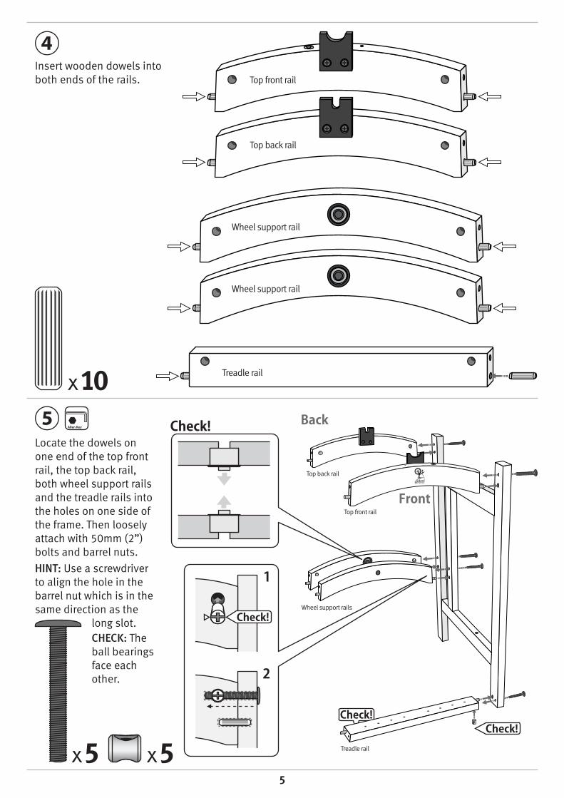
Insert wooden dowels into both ends of the rails.
Locate the dowels on one end of the top front rail, the top back rail, both wheel support rails and the treadle rails into the holes on one side of the frame. Then loosely attach with 50mm (2”) bolts and barrel nuts.
HINT: Use a screwdriver to align the hole in the barrel nut which is in the same direction as the
long slot.CHECK: The ball bearings face each other.
6
x5 x5
Hook the drive belt over the back flyer bearing and hang it between the 2 wheel support rails.
Position the wheel between the 2 wheel support rails.
CHECK: The smallest groove in the wheel is towards the front of the Spinner.
Position the other side onto the wooden dowels in the ends of the 5 rails. Then loosely attach all 5 rails with 50mm (2”) bolts and barrel nuts. Support the wheel and carefully lay the Spinner on its back to attach the treadle rail. Sit the Spinner back on its feet on a level surface.CHECK: The top and wheel support rails are parallel with the legs. Then tighten all bolts.NOTE: If the flyer “ticks” as it rotates, loosen the 2 bolts securing the front top rail and twist it about 1 degree forwards from vertical.
This ensures the ends of the steel split ring slide smoothly past the top of the bearing.
7
Rotate the wheel until the groove in the hub is in line with the hole in the crank and carefully tap the hub pin into position.
x1
Insert the crank through the ball bearing in the front wheel support, through the wheel and into the ball bearing in the rear wheel support.
If tight, loosen the bolts securing the wheel support rails, insert the crank and retighten.
CHECK: Make sure the drive belt is still around the wheel.
8
Locate the metal cover plates into the polyurethane hinges. Then attach the hinges to the treadle rail with 16mm (5/8”) screws.
Lay the Spinner on its back. Position the treadle boards against the hinges. Locate the metal cover plates into the polyurethane hinges.
CHECK: The treadle boards are parallel. Then attach the treadle boards to the hinges with 16mm (5/8”) screws.
x8
x8
9
Hold the conrod joint with one hand on either side of the treadle board.
With both hands turn the conrod joint a ¼ turn towards you.
Stretch and slide it up into the small slot and turn it back a ¼ turn until it clicks into place.
Repeat this sequence for the rear conrod and the left treadle board.
Slide the inner shell of the conrod universal joint onto the crank until it clicks into the groove.
Lay the Spinner on its back. Insert the front conrod joint into the large slot in right hand treadle board.
NOTE: The front conrod will attach to the right treadle board. The rear conrod will attach to the left treadle board.
10
Attach the leather brake to the front top rail with a 20mm (¾") round head screw.
Thread the tension knob through the leather brake band and into the front top rail.
Insert the 2 wooden lazy kate rods into the holes in the sides of the Spinner. If you want to ply your yarn, spare bobbins are available from your local Ashford Dealer.
HINT: The Spinner is bobbin lead and will require very little tension to draw the yarn onto the
bobbin. Only apply a minimum tension.
Apply a drop of oil to the flyer shaft and slide the bobbin onto it. Then position the flyer into the front and back flyer bearings. At the same time locate the stretchy drive belt on to the middle groove in the bobbin whorl & wrap it around the middle groove in the wheel.
CHECK: There should be 2-3mm (1/8”) clearance between the flyer and flyer bearings. If not loosen the bolts securing the top rails, adjust the clearance and retighten.
x1
2-3mm
11
Slow 3:1
Bobbin
Wheel
Medium 4:1 Fast 5:1
Large
Small
Small
Large
Medium
Medium
Remove drive belt when not in use to avoid it stretching.
RatioSlow 3:1 Use this ratio for extra bulky yarns with the least twist.
Medium 4:1 Use this ratio for medium to bulky yarns.
Fast 5:1 Use this ratio for fine to medium bulky yarns and plying.
MaintenanceTo make spinning easier apply a drop of Ashford Spinning Wheel Oil to the flyer, bobbin and conrod bearings.Note: The ball bearings are sealed for life and do not require oiling.
Ashford Handicrafts Limited415 West Street, Ashburton 7700, New ZealandTelephone 64 3 308 [email protected] www.ashford.co.nz
How to insert the polyurethane conrod joints into the conrod.*This has been pre-assembled in the factory.
Spinning on the Country Spinner 2 Because the Country Spinner 2 is bobbin lead, your yarn needs to be strong enough to turn the flyer.
- Place the drive belt on the slow ratio.
- Loosen the leather brake so there is no tension on the flyer shaft.
- Tie a 1.5m (5’) leader to the bobbin; wrap it around the flyer hooks & out through the flyer orifice.
- Start treadling slowly clockwise (60 RPM is ideal).
- Allow your prepared fibre to join onto the leader and feed the spun yarn onto the bobbin.
- If your yarn kinks, is over twisted or won’t feed on, treadle slower, draft a thinner yarn and increase the brake tension.
- If your yarn breaks, treadle faster or move to a higher ratio, draft a thicker yarn, reduce the brake tension and oil the bearings.
Refer to the Learn To Spin Booklet for more spinning hints.