American Society of Mechanical Engineers ASME Accepted Manuscript Repository Institutional Repository Cover Sheet Peter B Kreider First Last ASME Paper Title: Thermodynamic Analyses of Fuel Production Via Solar-Driven Ceria-Based Nonstoichiometric Redox Cycling: A Case Study of the Isothermal Membrane Reactor System Authors: Sha Li, Peter B. Kreider, Vincent M. Wheeler and Wojciech Lipiński ASME Journal Title: Journal of Solar Energy Engineering Volume/Issue 141/2___________________________ Date of Publication (VOR* Online) __8 January 2019_______________ ASME Digital Collection URL: http://solarenergyengineering.asmedigitalcollection.asme.org/article.aspx?articleid=27 DOI: 10.1115/1.4042228
Transcript
AmericanSocietyofMechanicalEngineers
ASMEAcceptedManuscriptRepository
InstitutionalRepositoryCoverSheet
Peter B
Kreider
First Last
ASME Paper Title:
Thermodynamic Analyses of Fuel Production Via Solar-Driven Ceria-Based Nonstoichiometric Redox Cycling: A Case Study of the Isothermal Membrane Reactor System
Authors: Sha Li, Peter B. Kreider, Vincent M. Wheeler and Wojciech Lipiński
ASME Journal Title: Journal of Solar Energy Engineering
Volume/Issue 141/2___________________________
Date of Publication (VOR* Online) __8 January
2019_______________
ASME Digital Collection URL:http://solarenergyengineering.asmedigitalcollection.asme.org/article.aspx?articleid=27
DOI: 10.1115/1.4042228
2
*VOR (version of record)
SOL-18-1424, Lipiński, page 1
Thermodynamic Analyses of Fuel Production via Solar-driven Ceria-based Non-
stoichiometric Redox Cycling: A Case Study of the Isothermal Membrane Reactor System
Sha Li, Peter B. Kreider, Vincent M. Wheeler, and Wojciech Lipiński1
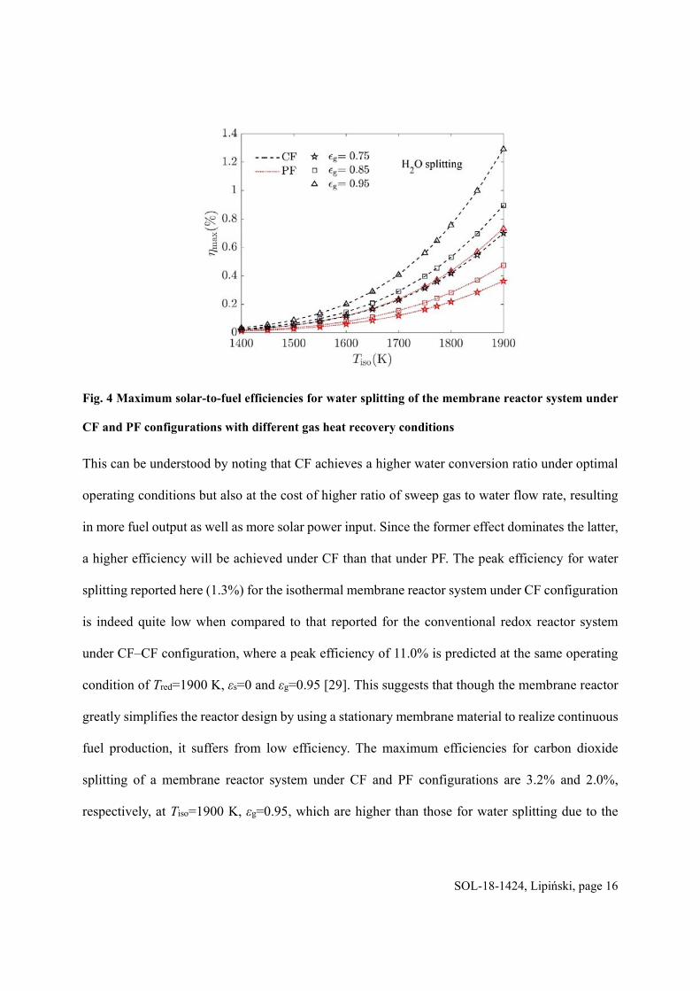
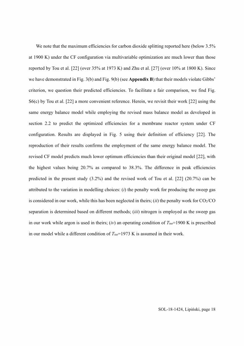
We note that the maximum efficiencies for carbon dioxide splitting reported here (below 3.5%
at 1900 K) under the CF configuration via multivariable optimization are much lower than those
reported by Tou et al. [22] (over 35% at 1973 K) and Zhu et al. [27] (over 10% at 1800 K). Since
we have demonstrated in Fig. 3(b) and Fig. 9(b) (see Appendix B) that their models violate Gibbs’
criterion, we question their predicted efficiencies. To facilitate a fair comparison, we find Fig.
S6(c) by Tou et al. [22] a more convenient reference. Herein, we revisit their work [22] using the
same energy balance model while employing the revised mass balance model as developed in
section 2.2 to predict the optimized efficiencies for a membrane reactor system under CF
configuration. Results are displayed in Fig. 5 using their definition of efficiency [22]. The
reproduction of their results confirms the employment of the same energy balance model. The
revised CF model predicts much lower optimum efficiencies than their original model [22], with
the highest values being 20.7% as compared to 38.3%. The difference in peak efficiencies
predicted in the present study (3.2%) and the revised work of Tou et al. [22] (20.7%) can be
attributed to the variation in modelling choices: (i) the penalty work for producing the sweep gas
is considered in our work, while this has been neglected in theirs; (ii) the penalty work for CO2/CO
separation is determined based on different methods; (iii) nitrogen is employed as the sweep gas
in our work while argon is used in theirs; (iv) an operating condition of Tiso=1900 K is prescribed
in our model while a different condition of Tiso=1973 K is assumed in their work.
SOL-18-1424, Lipiński, page 19
Fig. 5 Comparison of optimized efficiencies for carbon dioxide splitting with Tou et al. [22] (Fig. S6(c))
at εg=0.95, 2
6O ,red,in 10p atm for an isothermal membrane reactor system operated under CF
configuration. Legend text “reproduced” is in reference to the effort to reproduce the work by Tou
et al. [22], and “revised” refers to using the revised CF model to revisit, modify, and optimize the
work by Tou et al. [22]. The displayed values showcase the highest predicted solar-to-fuel efficiencies
using the respective CF models.
Next, we examine the dominating energy requirements behind the optimal results reported
above. Understanding the energetic constituents of total solar input can offer insight on reactor
design and operation. To facilitate our discussion, the system power outputs are normalized by the
total solar input so that their sum is 100%. This is conducted using CF configuration at the
optimized case as an example to help identify the dominating energy requirements at varying
temperature and gas heat recovery conditions.
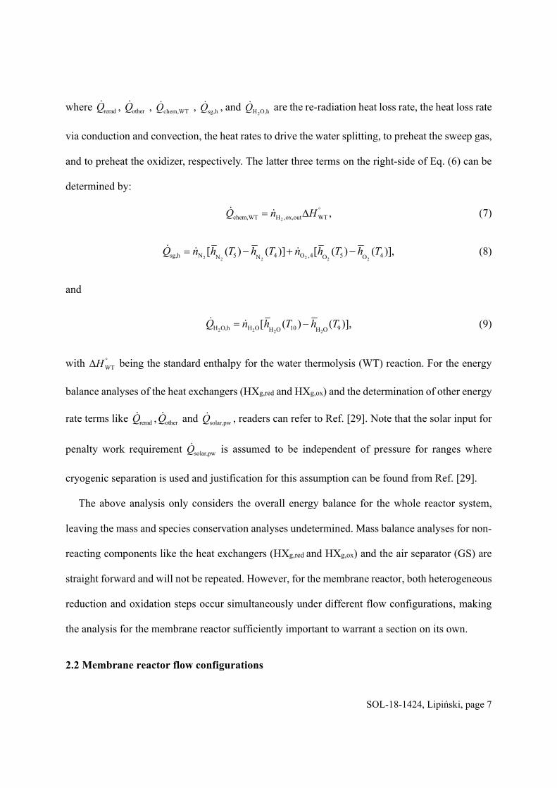
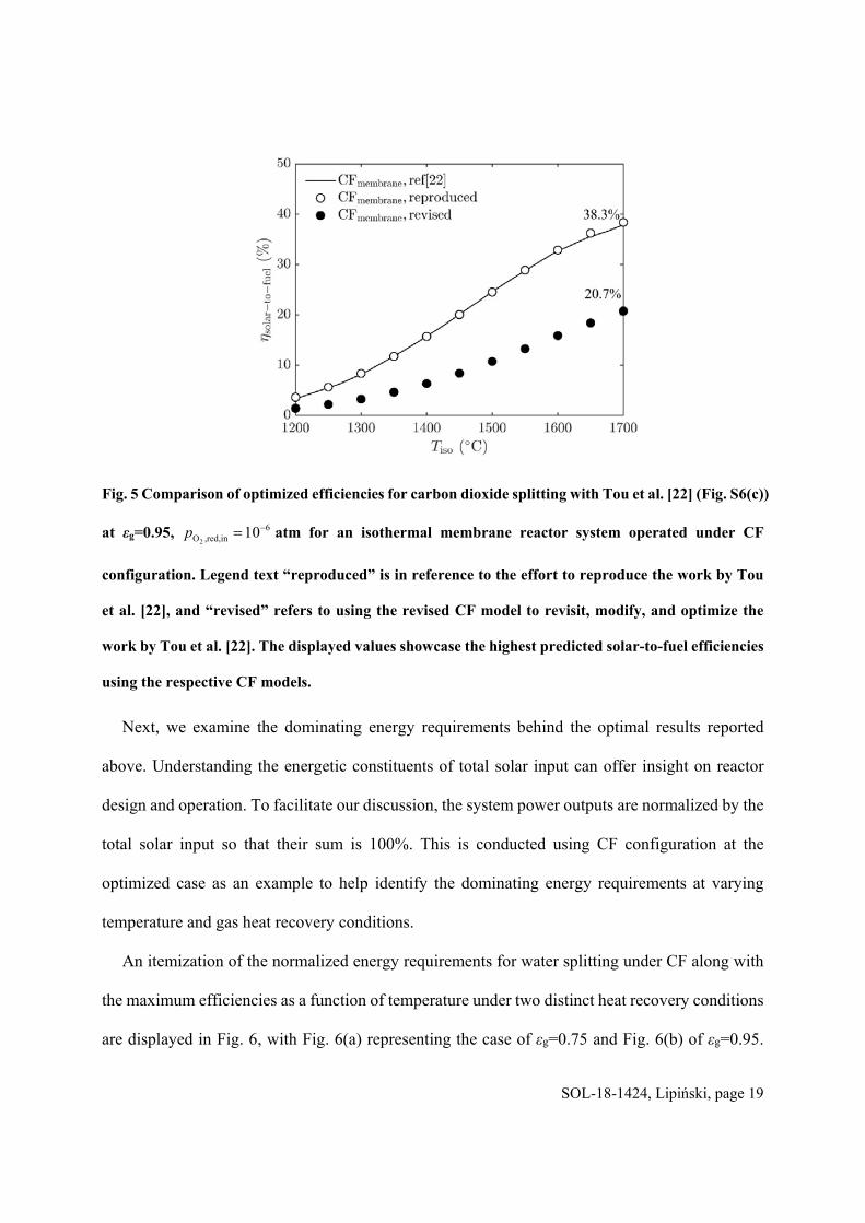
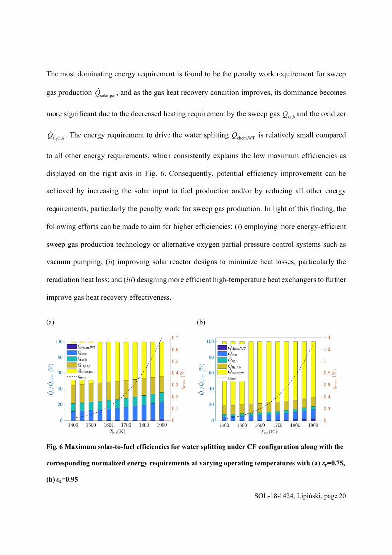
An itemization of the normalized energy requirements for water splitting under CF along with
the maximum efficiencies as a function of temperature under two distinct heat recovery conditions
are displayed in Fig. 6, with Fig. 6(a) representing the case of εg=0.75 and Fig. 6(b) of εg=0.95.
SOL-18-1424, Lipiński, page 20
The most dominating energy requirement is found to be the penalty work requirement for sweep
gas production solar,pwQ , and as the gas heat recovery condition improves, its dominance becomes
more significant due to the decreased heating requirement by the sweep gas sg,hQ and the oxidizer
2H O,hQ . The energy requirement to drive the water splitting chem,WTQ is relatively small compared
to all other energy requirements, which consistently explains the low maximum efficiencies as
displayed on the right axis in Fig. 6. Consequently, potential efficiency improvement can be
achieved by increasing the solar input to fuel production and/or by reducing all other energy
requirements, particularly the penalty work for sweep gas production. In light of this finding, the
following efforts can be made to aim for higher efficiencies: (i) employing more energy-efficient
sweep gas production technology or alternative oxygen partial pressure control systems such as
vacuum pumping; (ii) improving solar reactor designs to minimize heat losses, particularly the
reradiation heat loss; and (iii) designing more efficient high-temperature heat exchangers to further
improve gas heat recovery effectiveness.
(a) (b)
Fig. 6 Maximum solar-to-fuel efficiencies for water splitting under CF configuration along with the
corresponding normalized energy requirements at varying operating temperatures with (a) εg=0.75,
(b) εg=0.95
SOL-18-1424, Lipiński, page 21
3.2 Effect of free parameters
The effect of free parameters on solar-to-fuel efficiency is investigated to elucidate how changing
a certain free parameter causes deviation from the optimized efficiency conditions. The
investigation is conducted considering a membrane reactor operated under CF configuration at
Tiso=1900 K, εg=0.95. Only one free parameter is varied within a selected range while the other is
held constant at the optimal value as listed in Table 2. To facilitate the analysis, the solar-to-fuel
efficiency is reformulated via the introduction of dimensionless energy factor terms (Fi) following
the work by Jarrett et al. [5]:
2chem,WT loss sg,h H O,h solar,pw
1
F F F F F
(18)
with
2 2
2 2
2H H
rerad other
H H
H O
H
,( chem, WT; sg,h; pw)HHV
( =
,h;sol
loss)H
ar
V
i
i
Qi
nF
Q Qi
n
(19)
This enables the sum of all dimensionless energy factors to be the reciprocal of the solar-to-fuel
efficiency.
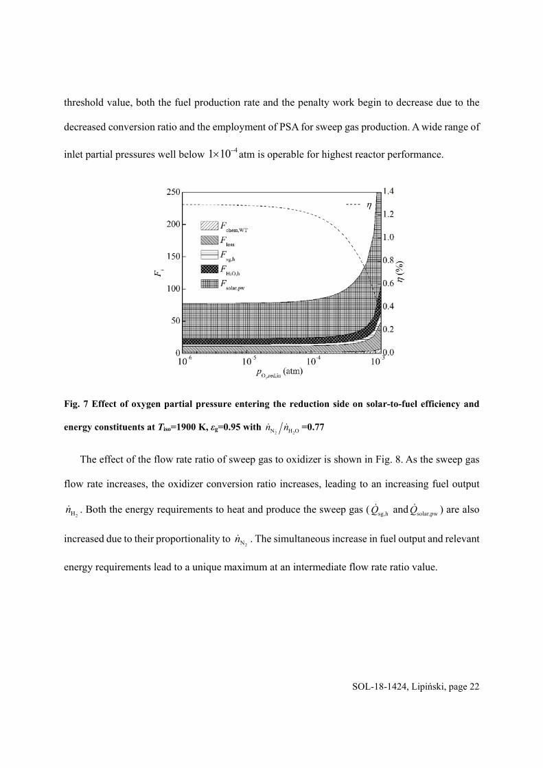
The effect of changes in the oxygen partial pressure entering the reduction side is illustrated in
Fig. 7. The solar-to-fuel efficiency is insensitive to changes in 2O ,red,inp over a broad range and
remains relatively constant within the range of 61 10 – 41 10 atm, after which the efficiency
begins to decrease gradually. This is not surprising since the optimal conversion ratio is always
achieved over the above wide range, creating a constant high fuel output. On the other hand, the
penalty work required to produce the sweep gas is assumed constant as long as cryogenic
separation can be used, making the solar input also constant [29]. Once 2O ,red,inp crosses the
SOL-18-1424, Lipiński, page 22
threshold value, both the fuel production rate and the penalty work begin to decrease due to the
decreased conversion ratio and the employment of PSA for sweep gas production. A wide range of
inlet partial pressures well below 41 10 atm is operable for highest reactor performance.
Fig. 7 Effect of oxygen partial pressure entering the reduction side on solar-to-fuel efficiency and
energy constituents at Tiso=1900 K, εg=0.95 with 2 2N H On n =0.77
The effect of the flow rate ratio of sweep gas to oxidizer is shown in Fig. 8. As the sweep gas
flow rate increases, the oxidizer conversion ratio increases, leading to an increasing fuel output
2Hn . Both the energy requirements to heat and produce the sweep gas ( sg,hQ and solar,pwQ ) are also
increased due to their proportionality to 2Nn . The simultaneous increase in fuel output and relevant
energy requirements lead to a unique maximum at an intermediate flow rate ratio value.
SOL-18-1424, Lipiński, page 23
Fig. 8 Effect of sweep gas to oxidizer flow rate ratio on solar-to-fuel efficiency and energy
constituents at Tiso=1900 K, εg=0.95 with 2
6O ,red,in 1 10p atm
4. Conclusions
A thermodynamic model based on conservation of mass and energy as well as Gibbs’ criterion has
been developed to predict the maximum efficiencies for a solar membrane reactor system via
simultaneous optimization of all variable parameters. Peak efficiencies along with their
corresponding optimal operating conditions are identified for two reactor flow configurations at
varying gas heat recovery conditions. The effect of operational parameters on the solar-to-fuel
efficiency has been examined.
A peak solar-to-fuel efficiency for water splitting (carbon dioxide splitting) has been found to
be 1.3% (3.2%) for CF configuration and 0.73% (2.0%) for PF configuration, respectively, at
operating temperature of 1900 K and 95% gas heat recovery. The CF configuration is demonstrated
to be more efficient than PF under the same heat recovery conditions. In terms of the optimal
operating conditions, the optimal oxygen partial pressure entering the reduction side remains
consistently low (10-6 atm) for both flow configurations under all gas heat recovery conditions.
SOL-18-1424, Lipiński, page 24
For the optimized case, the most dominating energy requirement has been identified to be the
penalty work requirement for sweep gas production. Its share of the total solar input has been
found to decrease from 55% to 44% and from 81% to 71% at εg=0.75 and εg=0.95, respectively,
when the operating temperature increases from 1400 K to 1900 K. The energy requirement to drive
the water splitting chem,WTQ has been found to be relatively small compared to all other terms,
agreeing with the low maximum efficiency result. The results reported above are found to be
independent of the membrane materials as long as the continuous fuel production at steady state is
guaranteed. The model results offered insights on potential efficiency improvement for membrane
reactor systems that help guide future reactor designs.
Acknowledgements
The financial support of the China Scholarship Council (Sha Li, grant no. [2015]3022,
201506020092) and the Australian Research Council (Wojciech Lipiński, Future Fellowship,
award no. FT140101213) is gratefully acknowledged.
Appendix A: an alternative method to derive Gibbs’ criterion for the membrane reactor
An alternative method to arrive at Eq. (14) can be obtained when Gibbs’ criterion is applied to the
whole membrane reactor system. At steady state the membrane material only serves as a pure
oxygen transport material. As a result, the overall net reaction will be simply water thermolysis,
with hydrogen generated on the oxidation side and oxygen transported across the membrane and
then released on the reduction side. Changes in the amount of each gaseous species are related to
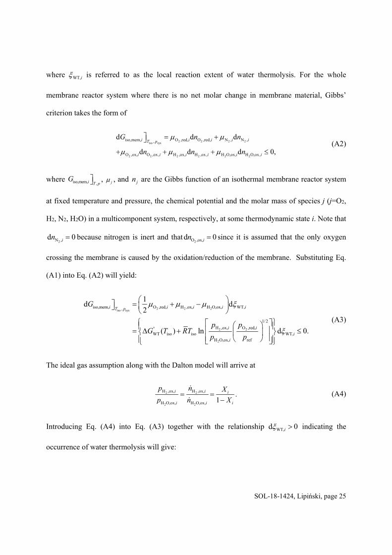
the stoichiometry coefficients of the overall water thermolysis reaction by:
2 2 2H O,ox, H ,ox, O ,red,WT,
d d dd
1 1 1 2i i i
i
n n n (A1)
SOL-18-1424, Lipiński, page 25
where WT,i is referred to as the local reaction extent of water thermolysis. For the whole
membrane reactor system where there is no net molar change in membrane material, Gibbs’
criterion takes the form of
2 2 2 2iso sys
2 2 2 2 2 2
iso,mem, O ,red, O ,red, N , N ,,
O ,ox, O ,ox, H ,ox, H ,ox, H O,ox, H O,ox,
d d d
d d d 0,
i i i i iT p
i i i i i i
G n n
n n n
(A2)
where iso,mem, ,i T pG , j , and jn are the Gibbs function of an isothermal membrane reactor system
at fixed temperature and pressure, the chemical potential and the molar mass of species j (j=O2,
H2, N2, H2O) in a multicomponent system, respectively, at some thermodynamic state i. Note that
2N ,d 0in because nitrogen is inert and that2O ,ox,d 0in since it is assumed that the only oxygen
crossing the membrane is caused by the oxidation/reduction of the membrane. Substituting Eq.
(A1) into Eq. (A2) will yield:
2 2 2iso sys
2 2
2
iso,mem, O ,red, H ,ox, H O,ox, WT,,
1/2
H ,ox, O ,red,WT iso iso WT,
H O,ox, ref
1d d
2
( ) ln d 0.
i i i i iT p
i ii
i
G
p pG T RT
p p
(A3)
The ideal gas assumption along with the Dalton model will arrive at
2 2
2 2
H ,ox, H ,ox,
H O,ox, H O,ox,
.1
i i i
i i i
p n X
p n X
(A4)
Introducing Eq. (A4) into Eq. (A3) together with the relationship WT,d 0i indicating the
occurrence of water thermolysis will give:
SOL-18-1424, Lipiński, page 26
2
1/2
O ,red,iso,mem, WT iso iso
ref
( ) ln 01
iii
i
pXG G T RT
X p
(A5)
which is exactly equivalent to Eq. (14). This suggests that Eq. (14) or (A5) can be interpreted as
the Gibbs criterion for the overall reaction of water thermolysis, with hydrogen produced on the
oxidation side while oxygen permeated through the membrane and then released on the reduction
side. However, since Eq. (A5) is derived based on the precondition of continuous oxygen transport
at steady state, Eq. (A5) holds true only when the membrane material satisfies both Eqs. (12) and
(13).
Appendix B: A graphical representation to determine the optimal conversion ratio for
carbon dioxide splitting
(a) (b)
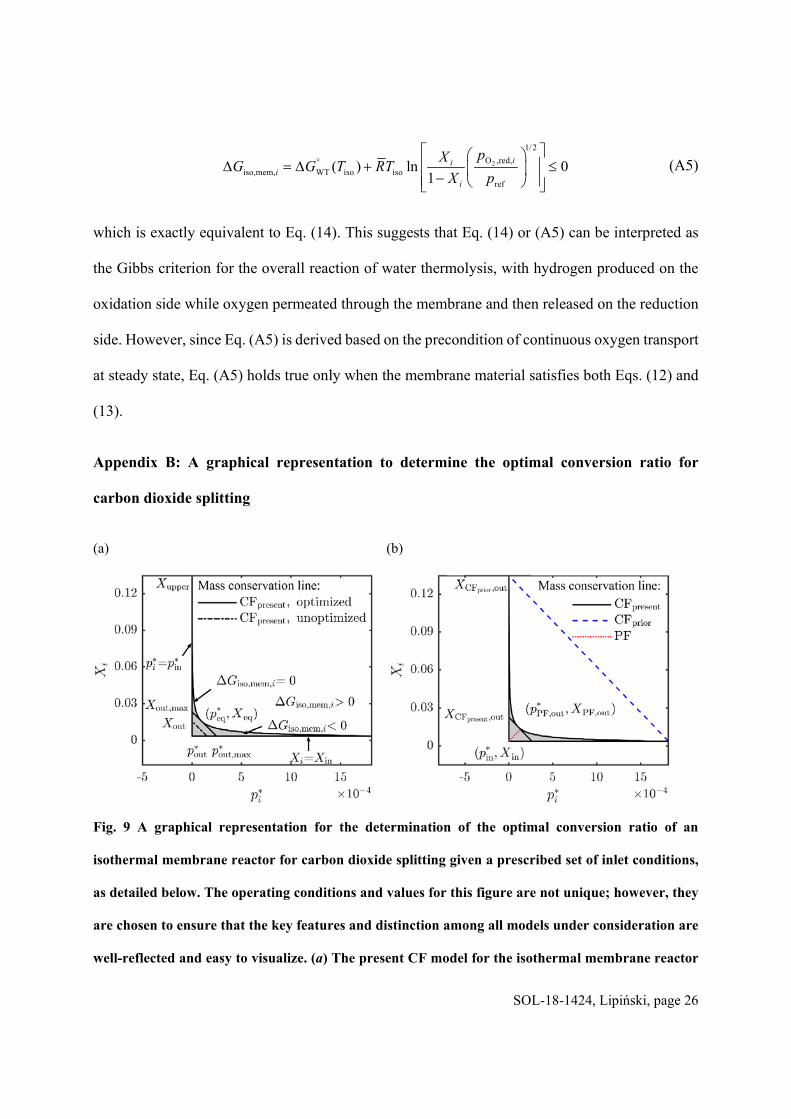
Fig. 9 A graphical representation for the determination of the optimal conversion ratio of an
isothermal membrane reactor for carbon dioxide splitting given a prescribed set of inlet conditions,
as detailed below. The operating conditions and values for this figure are not unique; however, they
are chosen to ensure that the key features and distinction among all models under consideration are
well-reflected and easy to visualize. (a) The present CF model for the isothermal membrane reactor
SOL-18-1424, Lipiński, page 27
at Tiso=1773 K with inlet conditions of * 6in 10 ,p and
2 2N COn n =40; and (b) comparison of CF and PF
models of the isothermal membrane reactor at Tiso=1773 K with inlet conditions of * 6in 10 ,p and
2 2N COn n =36.0 for all models under consideration. The subscript “prior” refers to the work by Tou
et al. [22] and Zhu et al. [27], and the subscript “present” refers to this work.
Appendix C: maximum solar-to-fuel efficiencies for carbon dioxide splitting
The maximum solar-to-fuel efficiencies of the membrane reactor system for carbon dioxide
splitting as a function of the operating temperature at varying gas recovery conditions are shown
in Fig. 10 under both CF and PF configurations. Unlike the case of water splitting, the penalty
work for carbon dioxide splitting includes two contributions: (i) the air separation work for sweep
gas production required in the reduction chamber; (ii) the product separation work of carbon
monoxide from the product mixtures. Readers can refer to Ref. [29] for detailed description.
Fig. 10 Maximum solar-to-fuel efficiencies for carbon dioxide splitting of the membrane reactor
system under CF and PF configurations with different gas heat recovery conditions
SOL-18-1424, Lipiński, page 28
Nomenclature
Aaperture=aperture area of reactor, m2
C= solar concentration ratio
DNI=direct normal irradiance, W m-2
dV=a differential control volume, m3
f=conduction and convection heat losses factor
F=dimensionless energy factor introduced in Eq. (18)
h =molar enthalpy, J mol-1
HHV= higher heating value, J mol−1
n =molar flow rate, mol s-1
p=pressure, atm
*p =dimensionless pressure as defined by 2 2
*O ,red, s
1
ys O ,red,i i ip p p p
Q =heat rate, W
R = universal molar gas constant, 8.314 J mol−1 K−1
s = molar entropy, J mol-1 K-1
T=temperature, K
w =molar separation work, J mol-1
W =work rate, W
X=conversion ratio
Greek Symbols
iso,memG = change in Gibbs function for isothermal membrane reactor, J mol−1
SOL-18-1424, Lipiński, page 29
2ox,H OG = standard molar Gibbs free energy for oxidation with water, J mol−1
2ox,OG = standard molar Gibbs free energy for oxidation with oxygen, J mol−1
redG = standard molar Gibbs free energy for reduction reaction, J mol−1
WTG = standard molar Gibbs free energy for WT reaction, J mol−1
oxH = standard molar enthalpy for oxidation with oxygen, -1OJ mol
redH = standard molar enthalpy for reduction reaction, -1OJ mol
WTH =standard molar enthalpy for WT reaction, J mol-1
°oxS = standard molar entropy for oxidation with oxygen, -1 -1
OJ K mol
°redS = standard molar entropy for reduction, -1 -1
OJ K mol
=non-stoichiometry swing
T =temperature swing, K
=non-stoichiometry
j = chemical potential of species j, J mol-1
=heat recovery effectiveness
=solar-to-fuel efficiency
solar-elec =solar-to-electricity efficiency
=Stefan–Boltzmann constant, W m-2 K-4
Subscripts
1,2…=thermodynamic state point
amb=ambient condition
chem,WT=chemical reaction of water thermolysis
SOL-18-1424, Lipiński, page 30
eq=equilibrium condition
g=gas phase
h=heating requirement
i=thermodynamic state
in=inlet
iso=isothermal
iso,mem=isothermal membrane reactor
L=lower limit
max=maximum
MO=metal oxide
other=other heat losses mode
out=outlet
ox=oxidation
ox,H2O=oxidation reaction with steam as given by Eq.(2)
ox,O2=oxidation reaction with oxygen
pw=penalty work
red=reduction
ref=reference condition
rerad=reradiation heat loss
s=solid phase
sg=sweep gas
solar=solar heat rate input
sys=system
SOL-18-1424, Lipiński, page 31
U=upper limit
Superscripts
=standard condition at T and patm
Abbreviations
CF=countercurrent flow
GS=gas separator
HX=heat exchanger
MO=metal oxide
OPM=oxygen permeation material
PF=parallel flow
PSA=pressure swing adsorption
WT=water thermolysis
References
[1] Chueh, W. C., Falter, C., Abbott, M., Scipio, D., Furler, P., Haile, S. M., and Steinfeld, A., 2010, "High-Flux Solar-Driven Thermochemical Dissociation of CO2 and H2O Using Nonstoichiometric Ceria," Science, 330(6012), pp. 1797–1801.
[2] Romero, M., Steinfeld, A., 2012, "Concentrating solar thermal power and thermochemical fuels," Energy & Environmental Science, 5(11), 9234.
[3] Lapp, J., Davidson, J. H., Lipiński, W., 2012, "Efficiency of two-step solar thermochemical non-stoichiometric redox cycles with heat recovery," Energy, 37(1), pp. 591–600.
[4] Krenzke, P. T., Davidson, J. H., 2015, "On the Efficiency of Solar H2 and CO Production via the Thermochemical Cerium Oxide Redox Cycle: The Option of Inert-Swept Reduction," Energy & Fuels, 29(2), pp. 1045–1054.
[5] Jarrett, C., Chueh, W., Yuan, C., Kawajiri, Y., Sandhage, K. H., Henry, A., 2016, "Critical limitations on the efficiency of two-step thermochemical cycles," Solar Energy, 123, pp. 57–73.
[6] Ermanoski, I., Miller, J. E., Allendorf, M. D., 2014, "Efficiency maximization in solar-thermochemical fuel production: challenging the concept of isothermal water splitting," Physical chemistry chemical physics : PCCP, 16(18), pp. 8418–8427.
[7] Marxer, D., Furler, P., Takacs, M., Steinfeld, A., 2017, "Solar thermochemical splitting of CO2 into separate streams of CO and O2 with high selectivity, stability, conversion, and efficiency," Energy & Environmental Science, 10(5), pp. 1142–1149.
SOL-18-1424, Lipiński, page 32
[8] Bader, R., Venstrom, L. J., Davidson, J. H., Lipiński, W., 2013, "Thermodynamic Analysis of Isothermal Redox Cycling of Ceria for Solar Fuel Production," Energy & Fuels, 27(9), pp. 5533–5544.
[9] Venstrom, L. J., De Smith, R. M., Hao, Y., Haile, S. M., Davidson, J. H., 2014, "Efficient Splitting of CO2 in an Isothermal Redox Cycle Based on Ceria," Energy & Fuels, 28(4), pp. 2732–2742.
[10] Muhich, C. L., Evanko, B. W., Weston, K. C., Lichty, P., Liang, X., Martinek, J., Musgrave, C. B., and Weimer, A. W., 2013, "Efficient generation of H2 by splitting water with an isothermal redox cycle," Science, 341(6145), pp. 540–542.
[11] Kong, H., Hao, Y., Jin, H., 2018, "Isothermal versus two-temperature solar thermochemical fuel synthesis: A comparative study," Applied Energy, 228, pp. 301–308.
[12] Al-Shankiti, I., Ehrhart, B. D., Weimer, A. W., 2017, "Isothermal redox for H2O and CO2 splitting—A review and perspective," Solar Energy, 156, pp. 21–29.
[13] Roeb, M., Neises, M., Säck, J.-P., Rietbrock, P., Monnerie, N., Dersch, J., Schmitz. M., and Sattler, C., 2009, "Operational strategy of a two-step thermochemical process for solar hydrogen production," International Journal of Hydrogen Energy, 34(10), pp. 4537–4545.
[14] Furler, P., Scheffe, J., Gorbar, M., Moes, L., Vogt, U., Steinfeld, A., 2012, "Solar Thermochemical CO2 Splitting Utilizing a Reticulated Porous Ceria Redox System," Energy & Fuels, 26(11), pp. 7051–7059.
[15] Lapp, J., Lipiński, W., 2014, "Transient Three-Dimensional Heat Transfer Model of a Solar Thermochemical Reactor for H2O and CO2 Splitting Via Nonstoichiometric Ceria Redox Cycling," Journal of Solar Energy Engineering, 136(3), 031006.
[16] Ermanoski, I., Siegel, N. P., Stechel, E. B., 2013, "A New Reactor Concept for Efficient Solar-Thermochemical Fuel Production," Journal of Solar Energy Engineering, 135(3), 031002.
[17] Diver, R. B., Miller, J. E., Allendorf, M. D., Siegel, N. P., Hogan, R. E., 2008, "Solar Thermochemical Water-Splitting Ferrite-Cycle Heat Engines," Journal of Solar Energy Engineering, 130(4), 041001.
[18] Fletcher, E. A., Moen, R. L., 1977, "Hydrogen-and oxygen from water," Science, 197(4308), pp. 1050–1056.
[19] Browall, K., Doremus, R., 1977, "Synthesis and Evaluation of Doped Y2O3‐Stabilized ZrO2 for the
Production of Hydrogen," Journal of the American Ceramic Society, 60(5‐6), pp. 262–267.
[20] Naito, H., Arashi, H., 1995, "Hydrogen production from direct water splitting at high temperatures using a ZrO2-TiO2-Y2O3 membrane," Solid State Ionics, 79, pp. 366–370.
[21] Wang, H., Hao, Y., Kong, H., 2015, "Thermodynamic study on solar thermochemical fuel production with oxygen permeation membrane reactors," International Journal of Energy Research, 39(13), pp. 1790–1799.
[22] Tou, M., Michalsky, R., Steinfeld, A., 2017, "Solar-Driven Thermochemical Splitting of CO2 and In Situ Separation of CO and O2 across a Ceria Redox Membrane Reactor," Joule, 1(1), pp. 146–154.
[23] Xu, S. J., Thomson, W. J., 1999, "Oxygen permeation rates through ion-conducting perovskite membranes," Chemical Engineering Science, 54(17), pp. 3839–3850.
[24] Tan, X., Li, K., 2002, "Modeling of air separation in a LSCF hollow‐fiber membrane module,"
AIChE journal, 48(7), pp. 1469–1477.
[25] Wu, X. Y., Ghoniem, A. F., 2018, "Hydrogen-assisted Carbon Dioxide Thermochemical Reduction on La0.9Ca0.1 FeO3-δ Membranes: A Kinetics Study," ChemSusChem, 11(2), pp. 483–493.
[26] Wu, X.-Y., Ghoniem, A. F., 2018, "CO2 reduction and methane partial oxidation on surface catalyzed La0.9 Ca0.1FeO3-δ oxygen transport membranes," Proceedings of the Combustion Institute (epub).
[27] Zhu, L., Lu, Y., Shen, S., 2016, "Solar fuel production at high temperatures using ceria as a dense membrane," Energy, 104, pp. 53–63.
SOL-18-1424, Lipiński, page 33
[28] Li, S., Wheeler, V. M., Kreider, P. B., Lipiński, W., 2018, "Thermodynamic Analyses of Fuel Production via Solar-Driven Non-stoichiometric Metal Oxide Redox Cycling. Part 1. Revisiting Flow and Equilibrium Assumptions," Energy & Fuels, 32(10), pp. 10838–10847.
[29] Li, S., Wheeler, V. M., Kreider, P. B., Bader, R., Lipiński, W., 2018, "Thermodynamic Analyses of Fuel Production via Solar-Driven Non-stoichiometric Metal Oxide Redox Cycling. Part 2. Impact of Solid–Gas Flow Configurations and Active Material Composition on System-Level Efficiency," Energy & Fuels, 32(10), pp. 10848–10863.
Table caption list
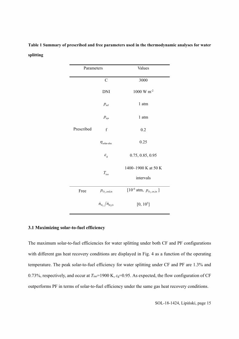
Table 1 Summary of prescribed and free parameters used in the thermodynamic analyses for water
splitting
Table 2 Peak efficiencies along with optimum operating conditions for water splitting under
varying gas heat recovery conditions
Figure caption list
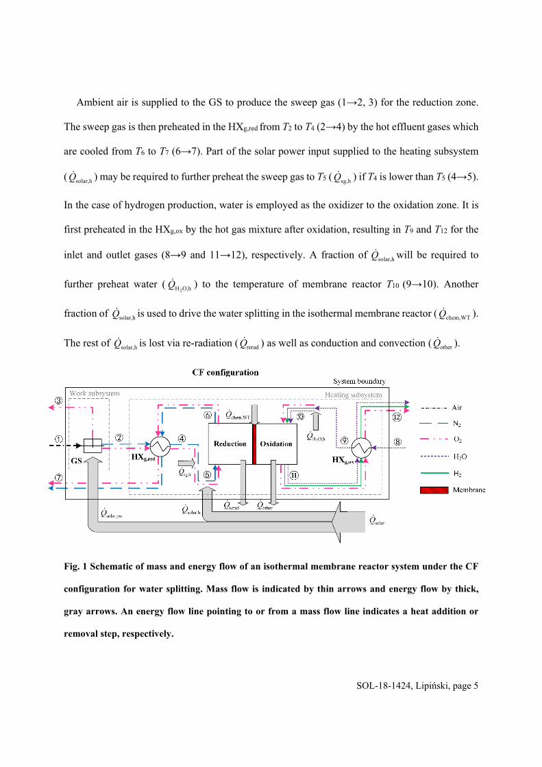
Fig. 1 Schematic of mass and energy flow of an isothermal membrane reactor system under the
CF configuration for water splitting. Mass flow is indicated by thin arrows and energy flow
by thick, gray arrows. An energy flow line pointing to or from a mass flow line indicates a
heat addition or removal step, respectively.
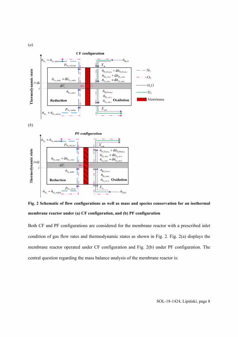
Fig. 2 Schematic of flow configurations as well as mass and species conservation for an isothermal
membrane reactor under (a) CF configuration, and (b) PF configuration
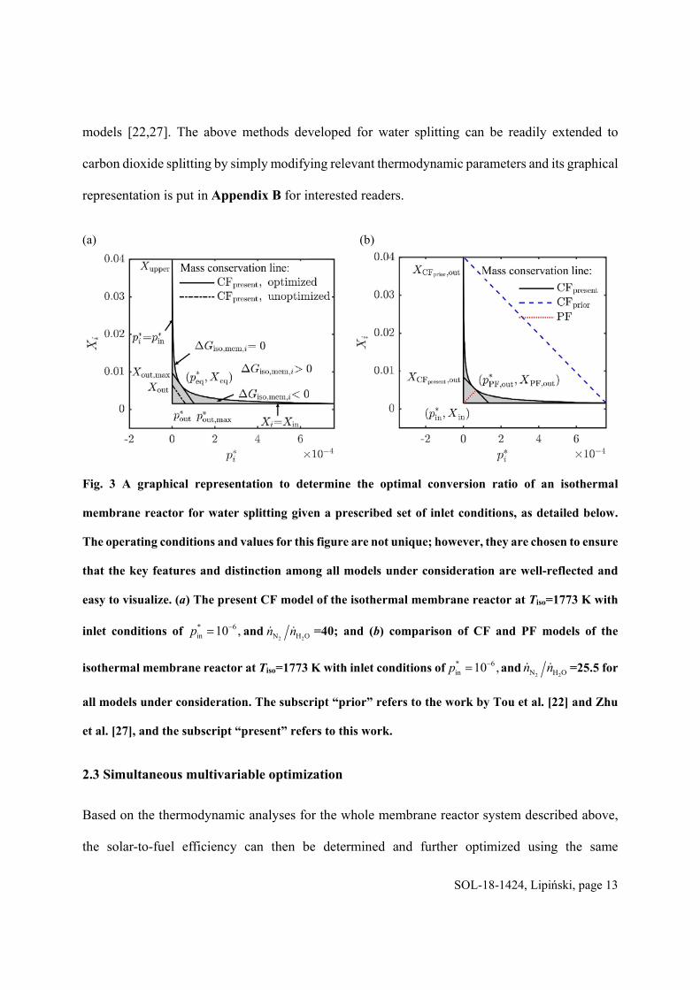
Fig. 3 A graphical representation to determine the optimal conversion ratio of an isothermal
membrane reactor for water splitting given a prescribed set of inlet conditions, as detailed
below. The operating conditions and values for this figure are not unique; however, they
are chosen to ensure that the key features and distinction among all models under
consideration are well-reflected and easy to visualize. (a) The present CF model of the
isothermal membrane reactor at Tiso=1773 K with inlet conditions of * 6in 10 ,p and
SOL-18-1424, Lipiński, page 34
2 2N H On n =40; and (b) comparison of CF and PF models of the isothermal membrane reactor
at Tiso=1773 K with inlet conditions of * 6in 10 ,p and
2 2N H On n =25.5 for all models under
consideration. The subscript “prior” refers to the work by Tou et al. [22] and Zhu et al. [27],
and the subscript “present” refers to this work.
Fig. 4 Maximum solar-to-fuel efficiencies for water splitting of the membrane reactor system
under CF and PF configurations with different gas heat recovery conditions
Fig. 5 Comparison of optimized efficiencies for carbon dioxide splitting with Tou et al. [22] (Fig.
S6(c)) at εg=0.95, 2
6O ,red,in 10p atm for an isothermal membrane reactor system operated
under CF configuration. Legend text “reproduced” is in reference to the effort to reproduce
the work by Tou et al. [22], and “revised” refers to using the revised CF model to revisit,
modify, and optimize the work by Tou et al. [22]. The displayed values showcase the
highest predicted solar-to-fuel efficiencies using the respective CF models.
Fig. 6 Maximum solar-to-fuel efficiencies for water splitting under CF configuration along with
the corresponding normalized energy requirements at varying operating temperatures with
(a) εg=0.75, (b) εg=0.95
Fig. 7 Effect of oxygen partial pressure entering the reduction side on solar-to-fuel efficiency and
energy constituents at Tiso=1900 K, εg=0.95 with 2 2N H On n =0.77
Fig. 8 Effect of sweep gas to oxidizer flow rate ratio on solar-to-fuel efficiency and energy
constituents at Tiso=1900 K, εg=0.95 with 2
6O ,red,in 1 10p atm
Fig. 9 A graphical representation for the determination of the optimal conversion ratio of an
isothermal membrane reactor for carbon dioxide splitting given a prescribed set of inlet
SOL-18-1424, Lipiński, page 35
conditions, as detailed below. The operating conditions and values for this figure are not
unique; however, they are chosen to ensure that the key features and distinction among all
models under consideration are well-reflected and easy to visualize. (a) The present CF
model for the isothermal membrane reactor at Tiso=1773 K with inlet conditions of
* 6in 10 ,p and
2 2N COn n =40; and (b) comparison of CF and PF models of the isothermal
membrane reactor at Tiso=1773 K with inlet conditions of * 6in 10 ,p and
2 2N COn n =36.0 for
all models under consideration. The subscript “prior” refers to the work by Tou et al. [22]
and Zhu et al. [27], and the subscript “present” refers to this work.
Fig. 10 Maximum solar-to-fuel efficiencies for carbon dioxide splitting of the membrane reactor
system under CF and PF configurations with different gas heat recovery conditions