352
Power Piping ASME Code for Pressure Piping, B31 AN AMERICAN NATIONAL STANDARD ASME B31.1-2010 (Revision of ASME B31.1-2007) --`,,```````,,```,`,`,,,,`,`,`,`-`-`,,`,,`,`,,`---
| Date post: | 28-Nov-2014 |
| Category: |
Documents |
| Upload: | mung-duong-xuan |
| View: | 4,794 times |
| Download: | 614 times |

Power Piping ASME Code for Pressure Piping, B31
A N A M E R I C A N N A T I O N A L S T A N D A R D
ASME B31.1-2010(Revision of ASME B31.1-2007)
Copyright ASME International Provided by IHS under license with ASME No reproduction or networking permitted without license from IHS
--`,,```````,,```,`,`,,,,`,`,`,`-`-`,,`,,`,`,,`---

INTENTIONALLY LEFT BLANK
Copyright ASME International Provided by IHS under license with ASME No reproduction or networking permitted without license from IHS
--`,,```````,,```,`,`,,,,`,`,`,`-`-`,,`,,`,`,,`---
标准分享网 www.bzfxw.com 免费下载
www.bzfxw.com
ASME B31.1-2010(Revision of ASME B31.1-2007)
Power PipingASME Code for Pressure Piping, B31
A N A M E R I C A N N A T I O N A L S T A N D A R D
Three Park Avenue • New York, NY • 10016 USA
Copyright ASME International Provided by IHS under license with ASME No reproduction or networking permitted without license from IHS
--`,,```````,,```,`,`,,,,`,`,`,`-`-`,,`,,`,`,,`---
www.bzfxw.com
Date of Issuance: December 31, 2010
The next edition of this Code is scheduled for publication in 2012. This Code will become effective6 months after the Date of Issuance. There will be no addenda issued to this edition.
ASME issues written replies to inquiries concerning interpretations of technical aspects of this Code.Interpretations, Code Cases, and errata are published on the ASME Web site under the CommitteePages at http://cstools.asme.org as they are issued. Interpretations and code cases are also includedwith each edition.
ASME is the registered trademark of The American Society of Mechanical Engineers.
This code or standard was developed under procedures accredited as meeting the criteria for American NationalStandards. The Standards Committee that approved the code or standard was balanced to assure that individuals fromcompetent and concerned interests have had an opportunity to participate. The proposed code or standard was madeavailable for public review and comment that provides an opportunity for additional public input from industry, academia,regulatory agencies, and the public-at-large.
ASME does not “approve,” “rate,” or “endorse” any item, construction, proprietary device, or activity.ASME does not take any position with respect to the validity of any patent rights asserted in connection with any
items mentioned in this document, and does not undertake to insure anyone utilizing a standard against liability forinfringement of any applicable letters patent, nor assume any such liability. Users of a code or standard are expresslyadvised that determination of the validity of any such patent rights, and the risk of infringement of such rights, isentirely their own responsibility.
Participation by federal agency representative(s) or person(s) affiliated with industry is not to be interpreted asgovernment or industry endorsement of this code or standard.
ASME accepts responsibility for only those interpretations of this document issued in accordance with the establishedASME procedures and policies, which precludes the issuance of interpretations by individuals.
No part of this document may be reproduced in any form,in an electronic retrieval system or otherwise,
without the prior written permission of the publisher.
The American Society of Mechanical EngineersThree Park Avenue, New York, NY 10016-5990
Copyright © 2010 byTHE AMERICAN SOCIETY OF MECHANICAL ENGINEERS
All rights reservedPrinted in U.S.A.
Copyright ASME International Provided by IHS under license with ASME No reproduction or networking permitted without license from IHS
--`,,```````,,```,`,`,,,,`,`,`,`-`-`,,`,,`,`,,`---
标准分享网 www.bzfxw.com 免费下载
www.bzfxw.com
CONTENTS
Foreword . . . . . . . . . . . . . . . . . . . . . . . . . . . . . . . . . . . . . . . . . . . . . . . . . . . . . . . . . . . . . . . . . . . . . . . . . . . . . . viCommittee Roster . . . . . . . . . . . . . . . . . . . . . . . . . . . . . . . . . . . . . . . . . . . . . . . . . . . . . . . . . . . . . . . . . . . . . viiIntroduction . . . . . . . . . . . . . . . . . . . . . . . . . . . . . . . . . . . . . . . . . . . . . . . . . . . . . . . . . . . . . . . . . . . . . . . . . . . xiSummary of Changes . . . . . . . . . . . . . . . . . . . . . . . . . . . . . . . . . . . . . . . . . . . . . . . . . . . . . . . . . . . . . . . . . . xiii
Chapter I Scope and Definitions. . . . . . . . . . . . . . . . . . . . . . . . . . . . . . . . . . . . . . . . . . . . . . . . . . . 1100 General . . . . . . . . . . . . . . . . . . . . . . . . . . . . . . . . . . . . . . . . . . . . . . . . . . . . . . . . . . . . . . . 1
Chapter II Design . . . . . . . . . . . . . . . . . . . . . . . . . . . . . . . . . . . . . . . . . . . . . . . . . . . . . . . . . . . . . . . . . 12Part 1 Conditions and Criteria . . . . . . . . . . . . . . . . . . . . . . . . . . . . . . . . . . . . . . . . . . . . . . . 12101 Design Conditions . . . . . . . . . . . . . . . . . . . . . . . . . . . . . . . . . . . . . . . . . . . . . . . . . . . . . 12102 Design Criteria . . . . . . . . . . . . . . . . . . . . . . . . . . . . . . . . . . . . . . . . . . . . . . . . . . . . . . . . 13Part 2 Pressure Design of Piping Components . . . . . . . . . . . . . . . . . . . . . . . . . . . . . . . 19103 Criteria for Pressure Design of Piping Components . . . . . . . . . . . . . . . . . . . . . 19104 Pressure Design of Components . . . . . . . . . . . . . . . . . . . . . . . . . . . . . . . . . . . . . . . 19Part 3 Selection and Limitations of Piping Components . . . . . . . . . . . . . . . . . . . . . 33105 Pipe . . . . . . . . . . . . . . . . . . . . . . . . . . . . . . . . . . . . . . . . . . . . . . . . . . . . . . . . . . . . . . . . . . 33106 Fittings, Bends, and Intersections . . . . . . . . . . . . . . . . . . . . . . . . . . . . . . . . . . . . . . 34107 Valves . . . . . . . . . . . . . . . . . . . . . . . . . . . . . . . . . . . . . . . . . . . . . . . . . . . . . . . . . . . . . . . . 35108 Pipe Flanges, Blanks, Flange Facings, Gaskets, and Bolting . . . . . . . . . . . . . 36Part 4 Selection and Limitations of Piping Joints . . . . . . . . . . . . . . . . . . . . . . . . . . . . 37110 Piping Joints . . . . . . . . . . . . . . . . . . . . . . . . . . . . . . . . . . . . . . . . . . . . . . . . . . . . . . . . . . 37111 Welded Joints . . . . . . . . . . . . . . . . . . . . . . . . . . . . . . . . . . . . . . . . . . . . . . . . . . . . . . . . . 37112 Flanged Joints . . . . . . . . . . . . . . . . . . . . . . . . . . . . . . . . . . . . . . . . . . . . . . . . . . . . . . . . . 37113 Expanded or Rolled Joints . . . . . . . . . . . . . . . . . . . . . . . . . . . . . . . . . . . . . . . . . . . . . 37114 Threaded Joints . . . . . . . . . . . . . . . . . . . . . . . . . . . . . . . . . . . . . . . . . . . . . . . . . . . . . . . 42115 Flared, Flareless, and Compression Joints, and Unions . . . . . . . . . . . . . . . . . . 42116 Bell End Joints . . . . . . . . . . . . . . . . . . . . . . . . . . . . . . . . . . . . . . . . . . . . . . . . . . . . . . . . 43117 Brazed and Soldered Joints . . . . . . . . . . . . . . . . . . . . . . . . . . . . . . . . . . . . . . . . . . . . 43118 Sleeve Coupled and Other Proprietary Joints . . . . . . . . . . . . . . . . . . . . . . . . . . . 43Part 5 Expansion, Flexibility, and Pipe Supporting Element . . . . . . . . . . . . . . . . . . 43119 Expansion and Flexibility . . . . . . . . . . . . . . . . . . . . . . . . . . . . . . . . . . . . . . . . . . . . . . 43120 Loads on Pipe Supporting Elements . . . . . . . . . . . . . . . . . . . . . . . . . . . . . . . . . . . 46121 Design of Pipe Supporting Elements . . . . . . . . . . . . . . . . . . . . . . . . . . . . . . . . . . . 47Part 6 Systems . . . . . . . . . . . . . . . . . . . . . . . . . . . . . . . . . . . . . . . . . . . . . . . . . . . . . . . . . . . . . . . 50122 Design Requirements Pertaining to Specific Piping Systems . . . . . . . . . . . . . 50
Chapter III Materials . . . . . . . . . . . . . . . . . . . . . . . . . . . . . . . . . . . . . . . . . . . . . . . . . . . . . . . . . . . . . . . 65123 General Requirements . . . . . . . . . . . . . . . . . . . . . . . . . . . . . . . . . . . . . . . . . . . . . . . . . 65124 Limitations on Materials . . . . . . . . . . . . . . . . . . . . . . . . . . . . . . . . . . . . . . . . . . . . . . . 66125 Materials Applied to Miscellaneous Parts . . . . . . . . . . . . . . . . . . . . . . . . . . . . . . 68
Chapter IV Dimensional Requirements . . . . . . . . . . . . . . . . . . . . . . . . . . . . . . . . . . . . . . . . . . . . . . 69126 Material Specifications and Standards for Standard and Nonstandard
Piping Components . . . . . . . . . . . . . . . . . . . . . . . . . . . . . . . . . . . . . . . . . . . . . . . . . 69
Chapter V Fabrication, Assembly, and Erection . . . . . . . . . . . . . . . . . . . . . . . . . . . . . . . . . . . . . . 77127 Welding . . . . . . . . . . . . . . . . . . . . . . . . . . . . . . . . . . . . . . . . . . . . . . . . . . . . . . . . . . . . . . . 77128 Brazing and Soldering . . . . . . . . . . . . . . . . . . . . . . . . . . . . . . . . . . . . . . . . . . . . . . . . . 88129 Bending and Forming . . . . . . . . . . . . . . . . . . . . . . . . . . . . . . . . . . . . . . . . . . . . . . . . . 89130 Requirements for Fabricating and Attaching Pipe Supports . . . . . . . . . . . . . 90131 Welding Preheat . . . . . . . . . . . . . . . . . . . . . . . . . . . . . . . . . . . . . . . . . . . . . . . . . . . . . . . 90
iii
Copyright ASME International Provided by IHS under license with ASME No reproduction or networking permitted without license from IHS
--`,,```````,,```,`,`,,,,`,`,`,`-`-`,,`,,`,`,,`---

www.bzfxw.com
132 Postweld Heat Treatment . . . . . . . . . . . . . . . . . . . . . . . . . . . . . . . . . . . . . . . . . . . . . . 91133 Stamping . . . . . . . . . . . . . . . . . . . . . . . . . . . . . . . . . . . . . . . . . . . . . . . . . . . . . . . . . . . . . 99135 Assembly . . . . . . . . . . . . . . . . . . . . . . . . . . . . . . . . . . . . . . . . . . . . . . . . . . . . . . . . . . . . . 99
Chapter VI Inspection, Examination, and Testing . . . . . . . . . . . . . . . . . . . . . . . . . . . . . . . . . . . . 101136 Inspection and Examination . . . . . . . . . . . . . . . . . . . . . . . . . . . . . . . . . . . . . . . . . . . 101137 Pressure Tests . . . . . . . . . . . . . . . . . . . . . . . . . . . . . . . . . . . . . . . . . . . . . . . . . . . . . . . . . 105
Chapter VII Operation and Maintenance . . . . . . . . . . . . . . . . . . . . . . . . . . . . . . . . . . . . . . . . . . . . . 108138 General . . . . . . . . . . . . . . . . . . . . . . . . . . . . . . . . . . . . . . . . . . . . . . . . . . . . . . . . . . . . . . . 108139 Operation and Maintenance Procedures . . . . . . . . . . . . . . . . . . . . . . . . . . . . . . . . 108140 Condition Assessment of CPS . . . . . . . . . . . . . . . . . . . . . . . . . . . . . . . . . . . . . . . . . . 108141 CPS Records . . . . . . . . . . . . . . . . . . . . . . . . . . . . . . . . . . . . . . . . . . . . . . . . . . . . . . . . . . 109
Figures100.1.2(A.1) Code Jurisdictional Limits for Piping — An Example of Forced Flow
Steam Generators With No Fixed Steam and Water Line . . . . . . . . . . . . . 2100.1.2(A.2) Code Jurisdictional Limits for Piping — An Example of Steam Separator
Type Forced Flow Steam Generators With No Fixed Steam and WaterLine . . . . . . . . . . . . . . . . . . . . . . . . . . . . . . . . . . . . . . . . . . . . . . . . . . . . . . . . . . . . . . . . 3
100.1.2(B) Code Jurisdictional Limits for Piping — Drum-Type Boilers . . . . . . . . . . . . 4100.1.2(C) Code Jurisdictional Limits for Piping — Spray-Type Desuperheater . . . . . 5102.4.5 Nomenclature for Pipe Bends . . . . . . . . . . . . . . . . . . . . . . . . . . . . . . . . . . . . . . . . . . 17104.3.1(D) Reinforcement of Branch Connections . . . . . . . . . . . . . . . . . . . . . . . . . . . . . . . . . . 24104.3.1(G) Reinforced Extruded Outlets . . . . . . . . . . . . . . . . . . . . . . . . . . . . . . . . . . . . . . . . . . . 28104.5.3 Types of Permanent Blanks . . . . . . . . . . . . . . . . . . . . . . . . . . . . . . . . . . . . . . . . . . . . 31104.8.4 Cross Section Resultant Moment Loading . . . . . . . . . . . . . . . . . . . . . . . . . . . . . . 33122.1.7(C) Typical Globe Valves . . . . . . . . . . . . . . . . . . . . . . . . . . . . . . . . . . . . . . . . . . . . . . . . . . 55122.4 Desuperheater Schematic Arrangement . . . . . . . . . . . . . . . . . . . . . . . . . . . . . . . . 59127.3 Butt Welding of Piping Components With Internal Misalignment . . . . . . . 78127.4.2 Welding End Transition — Maximum Envelope . . . . . . . . . . . . . . . . . . . . . . . . 79127.4.4(A) Fillet Weld Size . . . . . . . . . . . . . . . . . . . . . . . . . . . . . . . . . . . . . . . . . . . . . . . . . . . . . . . . 82127.4.4(B) Welding Details for Slip-On and Socket-Welding Flanges; Some
Acceptable Types of Flange Attachment Welds . . . . . . . . . . . . . . . . . . . . . . . 83127.4.4(C) Minimum Welding Dimensions Required for Socket Welding
Components Other Than Flanges . . . . . . . . . . . . . . . . . . . . . . . . . . . . . . . . . . . . 83127.4.8(A) Typical Welded Branch Connection Without Additional
Reinforcement . . . . . . . . . . . . . . . . . . . . . . . . . . . . . . . . . . . . . . . . . . . . . . . . . . . . . . . 83127.4.8(B) Typical Welded Branch Connection With Additional Reinforcement . . . . . 83127.4.8(C) Typical Welded Angular Branch Connection Without Additional
Reinforcement . . . . . . . . . . . . . . . . . . . . . . . . . . . . . . . . . . . . . . . . . . . . . . . . . . . . . . 83127.4.8(D) Some Acceptable Types of Welded Branch Attachment Details
Showing Minimum Acceptable Welds . . . . . . . . . . . . . . . . . . . . . . . . . . . . . . . 84127.4.8(E) Some Acceptable Details for Integrally Reinforced Outlet Fittings . . . . . . . 85127.4.8(F) Typical Full Penetration Weld Branch Connections for NPS 3 and
Smaller Half Couplings or Adapters . . . . . . . . . . . . . . . . . . . . . . . . . . . . . . . . . 86127.4.8(G) Typical Partial Penetration Weld Branch Connection for NPS 2 and
Smaller Fittings . . . . . . . . . . . . . . . . . . . . . . . . . . . . . . . . . . . . . . . . . . . . . . . . . . . . . 87135.5.3 Typical Threaded Joints Using Straight Threads . . . . . . . . . . . . . . . . . . . . . . . . 100
Tables102.4.3 Longitudinal Weld Joint Efficiency Factors . . . . . . . . . . . . . . . . . . . . . . . . . . . . . 16102.4.5 Bend Thinning Allowance . . . . . . . . . . . . . . . . . . . . . . . . . . . . . . . . . . . . . . . . . . . . . 17102.4.6(B.1.1) Maximum Severity Level for Casting Thickness 41⁄2 in. (114 mm) or
Less . . . . . . . . . . . . . . . . . . . . . . . . . . . . . . . . . . . . . . . . . . . . . . . . . . . . . . . . . . . . . . . . 18102.4.6(B.2.2) Maximum Severity Level for Casting Thickness Greater Than 41⁄2 in.
(114 mm) . . . . . . . . . . . . . . . . . . . . . . . . . . . . . . . . . . . . . . . . . . . . . . . . . . . . . . . . . . . 18
iv
Copyright ASME International Provided by IHS under license with ASME No reproduction or networking permitted without license from IHS
--`,,```````,,```,`,`,,,,`,`,`,`-`-`,,`,,`,`,,`---
标准分享网 www.bzfxw.com 免费下载

www.bzfxw.com
102.4.7 Weld Strength Reduction Factors to Be Applied When Calculating theMinimum Wall Thickness or Allowable Design Pressure ofComponents Fabricated With a Longitudinal Seam Fusion Weld . . . . . . 20
104.1.2(A) Values of y . . . . . . . . . . . . . . . . . . . . . . . . . . . . . . . . . . . . . . . . . . . . . . . . . . . . . . . . . . . . 22112 Piping Flange Bolting, Facing, and Gasket Requirements . . . . . . . . . . . . . . . 38114.2.1 Threaded Joints Limitations . . . . . . . . . . . . . . . . . . . . . . . . . . . . . . . . . . . . . . . . . . . . 42121.5 Suggested Pipe Support Spacing . . . . . . . . . . . . . . . . . . . . . . . . . . . . . . . . . . . . . . . 48121.7.2(A) Carrying Capacity of Threaded ASTM A 36, A 575, and A 576
Hot-Rolled Carbon Steel . . . . . . . . . . . . . . . . . . . . . . . . . . . . . . . . . . . . . . . . . . . . . 49122.2 Design Pressure for Blowoff/Blowdown Piping Downstream of BEP
Valves . . . . . . . . . . . . . . . . . . . . . . . . . . . . . . . . . . . . . . . . . . . . . . . . . . . . . . . . . . . . . . 55122.8.2(B) Minimum Wall Thickness Requirements for Toxic Fluid Piping . . . . . . . . . 62126.1 Specifications and Standards . . . . . . . . . . . . . . . . . . . . . . . . . . . . . . . . . . . . . . . . . . . 70127.4.2 Reinforcement of Girth and Longitudinal Butt Welds . . . . . . . . . . . . . . . . . . . 81129.3.1 Approximate Lower Critical Temperatures . . . . . . . . . . . . . . . . . . . . . . . . . . . . . 89132 Postweld Heat Treatment . . . . . . . . . . . . . . . . . . . . . . . . . . . . . . . . . . . . . . . . . . . . . . 92132.1 Alternate Postweld Heat Treatment Requirements for Carbon and
Low Alloy Steels . . . . . . . . . . . . . . . . . . . . . . . . . . . . . . . . . . . . . . . . . . . . . . . . . . . . 97136.4 Mandatory Minimum Nondestructive Examinations for Pressure
Welds or Welds to Pressure-Retaining Components . . . . . . . . . . . . . . . . . . . 103136.4.1 Weld Imperfections Indicated by Various Types of Examination . . . . . . . . . 104
Mandatory AppendicesA Table A-1, Carbon Steel . . . . . . . . . . . . . . . . . . . . . . . . . . . . . . . . . . . . . . . . . . . . . . . . 112
Table A-2, Low and Intermediate Alloy Steel . . . . . . . . . . . . . . . . . . . . . . . . . . . 124Table A-3, Stainless Steels . . . . . . . . . . . . . . . . . . . . . . . . . . . . . . . . . . . . . . . . . . . . . 134Table A-4, Nickel and High Nickel Alloys . . . . . . . . . . . . . . . . . . . . . . . . . . . . . . 164Table A-5, Cast Iron . . . . . . . . . . . . . . . . . . . . . . . . . . . . . . . . . . . . . . . . . . . . . . . . . . . 176Table A-6, Copper and Copper Alloys . . . . . . . . . . . . . . . . . . . . . . . . . . . . . . . . . . 178Table A-7, Aluminum and Aluminum Alloys . . . . . . . . . . . . . . . . . . . . . . . . . . . 182Table A-8, Temperatures 1,200°F and Above . . . . . . . . . . . . . . . . . . . . . . . . . . . . 190Table A-9, Titanium and Titanium Alloys . . . . . . . . . . . . . . . . . . . . . . . . . . . . . . 196Table A-10, Bolts, Nuts, and Studs . . . . . . . . . . . . . . . . . . . . . . . . . . . . . . . . . . . . . 200
B Table B-1, Thermal Expansion Data . . . . . . . . . . . . . . . . . . . . . . . . . . . . . . . . . . . . 206Table B-1 (SI), Thermal Expansion Data . . . . . . . . . . . . . . . . . . . . . . . . . . . . . . . . 210
C Table C-1, Moduli of Elasticity for Ferrous Material . . . . . . . . . . . . . . . . . . . . . 214Table C-1 (SI), Moduli of Elasticity for Ferrous Material . . . . . . . . . . . . . . . . 215Table C-2, Moduli of Elasticity for Nonferrous Material . . . . . . . . . . . . . . . . . 216Table C-2 (SI), Moduli of Elasticity for Nonferrous Material . . . . . . . . . . . . . 218
D Table D-1, Flexibility and Stress Intensification Factors . . . . . . . . . . . . . . . . . . 220Chart D-1, Flexibility Factor, k, and Stress Intensification Factor, i . . . . . . . 224Chart D-2, Correction Factor, c . . . . . . . . . . . . . . . . . . . . . . . . . . . . . . . . . . . . . . . . . 225Fig. D-1, Branch Connection Dimensions . . . . . . . . . . . . . . . . . . . . . . . . . . . . . . . 226
F Referenced Standards . . . . . . . . . . . . . . . . . . . . . . . . . . . . . . . . . . . . . . . . . . . . . . . . . . 227G Nomenclature . . . . . . . . . . . . . . . . . . . . . . . . . . . . . . . . . . . . . . . . . . . . . . . . . . . . . . . . . 231H Preparation of Technical Inquiries . . . . . . . . . . . . . . . . . . . . . . . . . . . . . . . . . . . . . . 237J Quality Control Requirements for Boiler External Piping (BEP) . . . . . . . . . 238
Nonmandatory AppendicesII Rules for the Design of Safety Valve Installations . . . . . . . . . . . . . . . . . . . . . . . 240III Rules for Nonmetallic Piping and Piping Lined With Nonmetals . . . . . . . . 260IV Corrosion Control for ASME B31.1 Power Piping Systems . . . . . . . . . . . . . . 280V Recommended Practice for Operation, Maintenance, and
Modification of Power Piping Systems . . . . . . . . . . . . . . . . . . . . . . . . . . . . . . . 284VI Approval of New Materials . . . . . . . . . . . . . . . . . . . . . . . . . . . . . . . . . . . . . . . . . . . . 294VII Procedures for the Design of Restrained Underground Piping . . . . . . . . . . . 295
Index . . . . . . . . . . . . . . . . . . . . . . . . . . . . . . . . . . . . . . . . . . . . . . . . . . . . . . . . . . . . . . . . . . . . . . . . . . . . . . . . . . 306
v
Copyright ASME International Provided by IHS under license with ASME No reproduction or networking permitted without license from IHS
--`,,```````,,```,`,`,,,,`,`,`,`-`-`,,`,,`,`,,`---

www.bzfxw.com
FOREWORD
The general philosophy underlying this Power Piping Code is to parallel those provisions ofSection I, Power Boilers, of the ASME Boiler and Pressure Vessel Code, as they can be appliedto power piping systems. The Allowable Stress Values for power piping are generally consistentwith those assigned for power boilers. This Code is more conservative than some other pipingcodes, reflecting the need for long service life and maximum reliability in power plant installations.
The Power Piping Code as currently written does not differentiate among the design, fabrication,and erection requirements for critical and noncritical piping systems, except for certain stresscalculations and mandatory nondestructive tests of welds for heavy wall, high temperatureapplications. The problem involved is to try to reach agreement on how to evaluate criticality,and to avoid the inference that noncritical systems do not require competence in design, fabrication,and erection. Someday such levels of quality may be definable, so that the need for the manydifferent piping codes will be overcome.
There are many instances where the Code serves to warn a designer, fabricator, or erectoragainst possible pitfalls; but the Code is not a handbook, and cannot substitute for education,experience, and sound engineering judgment.
Nonmandatory Appendices are included in the Code. Each contains information on a specificsubject, and is maintained current with the Code. Although written in mandatory language, theseAppendices are offered for application at the user’s discretion.
The Code never intentionally puts a ceiling limit on conservatism. A designer is free to specifymore rigid requirements as he feels they may be justified. Conversely, a designer who is capableof a more rigorous analysis than is specified in the Code may justify a less conservative design,and still satisfy the basic intent of the Code.
The Power Piping Committee strives to keep abreast of the current technological improvementsin new materials, fabrication practices, and testing techniques; and endeavors to keep the Codeupdated to permit the use of acceptable new developments.
vi
Copyright ASME International Provided by IHS under license with ASME No reproduction or networking permitted without license from IHS
--`,,```````,,```,`,`,,,,`,`,`,`-`-`,,`,,`,`,,`---
标准分享网 www.bzfxw.com 免费下载
ASME B31 COMMITTEECode for Pressure Piping
(The following is the roster of the Committee at the time of approval of this Code.)
STANDARDS COMMITTEE OFFICERS
M. L. Nayyar, ChairK. C. Bodenhamer, Vice Chair
N. Lobo, Secretary
STANDARDS COMMITTEE PERSONNEL
R. J. T. Appleby, Pipeline Experts, LLCC. Becht IV, Becht Engineering Co.A. E. Beyer, Fluor EnterprisesK. C. Bodenhamer, Enterprise Products Co.C. J. Campbell, Air LiquideJ. S. Chin, TransCanada Pipeline U.S.D. D. Christian, VictaulicD. L. Coym, WorleyParsonsC. J. Melo, Alternate, WorleyParsonsR. P. Deubler, Fronek Power Systems, LLCJ. A. Drake, Spectra Energy TransmissionP. D. Flenner, Flenner Engineering ServicesJ. W. Frey, Stress Engineering Services, Inc.D. R. Frikken, Becht Engineering Co.R. A. Grichuk, Fluor Corp.R. W. Haupt, Pressure Piping Engineering Associates, Inc.L. E. Hayden, Jr., ConsultantB. P. Holbrook, Babcock Power, Inc.
B31.1 POWER PIPING SECTION COMMITTEE
J. W. Frey, Chair, Stress Engineering Services, Inc.W. J. Mauro, Vice Chair, American Electric PowerC. E. O’Brien, Secretary, The American Society of Mechanical
EngineersH. A. Ainsworth, ConsultantD. D. Christian, VictaulicM. J. Cohn, Intertek–AptechD. H. Creates, Ontario Power Generation, Inc.G. J. Delude, PenpowerR. P. Deubler, Fronek Power Systems, LLCA. S. Drake, Constellation Energy GroupS. J. Findlan, Electric Power Research InstituteP. D. Flenner, Flenner Engineering ServicesE. C. Goodling, Jr., WorleyParsonsJ. W. Goodwin, Southern Co.T. E. Hansen, American Electric PowerR. W. Haupt, Pressure Piping Engineering Associates, Inc.C. L. Henley, Black & VeatchB. P. Holbrook, Babcock Power, Inc.
vii
G. A. Jolly, Vogt Valves/Flowserve Corp.N. Lobo, The American Society of Mechanical EngineersW. J. Mauro, American Electric PowerJ. E. Meyer, Louis Perry & Associates, Inc.M. L. Nayyar, Bechtel Power Corp.R. G. Payne, Alstom Power, Inc.G. R. Petru, Engineering Products Co.E. H. Rinaca, Dominion Resources, Inc.M. J. Rosenfeld, Kiefner & Associates, Inc.R. J. Silvia, Process Engineers and Constructors, Inc.W. J. Sperko, Sperko Engineering Services, Inc.F. W. Tatar, FM GlobalK. A. Vilminot, Black & VeatchK. H. Wooten, ConocoPhillips Pipe Line Co.A. Soni, Delegate, Engineers India Ltd.W. J. Koves, Ex-OfficioA. P. Rangus, Ex-Officio, BechtelR. A. Appleton, Contributing Member, Refrigeration Systems Co.
J. Kaliyadan, DominionR. J. Kennedy, Detroit Edison Co.D. J. Leininger, WorleyParsonsS. P. Licud, Weirich Consulting Services, Inc.W. M. Lundy, U.S. Coast GuardD. C. Moore, Southern Co. Services, Inc.M. L. Nayyar, Bechtel Power Corp.R. G. Payne, Alstom Power, Inc.D. W. Rahoi, CCM 2000K. I. Rapkin, FPLR. K. Reamey, Turner Industries Group, LLCE. H. Rinaca, Dominion Resources, Inc.R. D. Schueler, Jr., The National Board of Boiler and Pressure
Vessel InspectorsJ. P. Scott, DominionJ. J. Sekely, Welding Services, Inc.H. R. Simpson, Industry and Energy Associates, LLCS. K. Sinha, Lucius Pitkin, Inc.K. A. Vilminot, Black & VeatchA. L. Watkins, First Energy Corp.
Copyright ASME International Provided by IHS under license with ASME No reproduction or networking permitted without license from IHS
--`,,```````,,```,`,`,,,,`,`,`,`-`-`,,`,,`,`,,`---

B31.1 SUBGROUP ON DESIGN
K. A. Vilminot, Chair, Black & VeatchD. H. Creates, Ontario Power Generation, Inc.S. D. Cross, Zachry EngineeringM. K. Engelkemier, Stanley Consultants, Inc.J. W. Goodwin, Southern Co.R. W. Haupt, Pressure Piping Engineering Associates, Inc.B. P. Holbrook, Babcock Power, Inc.M. W. Johnson, RRI EnergyR. J. Kennedy, Detroit Edison Co.
B31.1 SUBGROUP ON FABRICATION AND EXAMINATION
R. K. Reamey, Chair, Turner Industries Group, LLCR. B. Corbit, Exelon NuclearP. M. Davis, Foster Wheeler North America Corp.C. EmslanderS. J. Findlan, Electric Power Research InstituteP. D. Flenner, Flenner Engineering ServicesJ. W. Frey, Stress Engineering Services, Inc.S. E. Gingrich, URS Corp.
B31.1 SUBGROUP ON GENERAL REQUIREMENTS
W. J. Mauro, Chair, American Electric PowerH. A. Ainsworth, ConsultantD. D. Christian, VictaulicG. J. Delude, PenpowerJ. Kaliyadan, Dominion
B31.1 SUBGROUP ON MATERIALS
D. W. Rahoi, Chair, CCM 2000M. G. BarkanR. P. Deubler, Fronek Power Systems, LLCP. J. Dobson, Electricity de FranceA. S. Drake, Constellation Energy GroupC. L. Henley, Black & Veatch
B31.1 SUBGROUP ON OPERATION AND MAINTENANCE
R. J. Kennedy, Chair, Detroit Edison Co.C. E. O’Brien, Secretary, The American Society of Mechanical
EngineersM. J. Cohn, Intertek–AptechD. H. Creates, Ontario Power Generation, Inc.P. M. Davis, Foster Wheeler North America Corp.M. K. Engelkemier, Stanley Consultants, Inc.P. D. Flenner, Flenner Engineering ServicesJ. W. Frey, Stress Engineering Services, Inc.E. C. Goodling, Jr., WorleyParsonsJ. W. Goodwin, Southern Co.T. E. Hansen, American Electric Power
viii
W. M. Lundy, U.S. Coast GuardD. C. Moore, Southern Co. Services, Inc.A. D. Nance, ConsultantR. D. Patel, GE Energy NuclearR. G. Payne, Alstom Power, Inc.D. D. Pierce, Puget Sound Naval ShipyardK. I. Rapkin, FPLT. Sato, Japan Power Engineering and Inspection Corp.A. L. Watkins, First Energy Corp.R. B. Wilson, TWD Technologies Ltd.
J. Hainsworth, The Babcock & Wilcox Co.T. E. Hansen, American Electric PowerD. J. Leininger, WorleyParsonsS. P. Licud, Weirich Consulting Services, Inc.T. Monday, Team Industries, Inc.J. J. Sekely, Welding Services, Inc.E. F. Summers, Jr., Babcock & Wilcox Construction Co.E. F. Gerwin, Honorary Member
J. W. Power, Alstom Power, Inc.R. D. Schueler, Jr., The National Board of Boiler and Pressure
Vessel InspectorsM. A. Treat, Associated Electric Cooperative, Inc.
S. L. McCracken, Electric Power Research InstituteL. C. McDonald, Structural Integrity Associates, Inc.M. L. Nayyar, Bechtel Power Corp.W. M. Sherman, Swagelok Co.N. S. Tambat, Bechtel Corp.
R. W. Haupt, Pressure Piping Engineering Associates, Inc.B. P. Holbrook, Babcock Power, Inc.M. W. Johnson, RRI EnergyL. C. McDonald, Structural Integrity Associates, Inc.D. C. Moore, Southern Co. Services, Inc.M. L. Nayyar, Bechtel Power Corp.R. G. Payne, Alstom Power, Inc.K. I. Rapkin, FPLR. K. Reamey, Turner Industries Group, LLCE. H. Rinaca, Dominion Resources, Inc.J. P. Scott, DominionA. L. Watkins, First Energy Corp.
Copyright ASME International Provided by IHS under license with ASME No reproduction or networking permitted without license from IHS
--`,,```````,,```,`,`,,,,`,`,`,`-`-`,,`,,`,`,,`---标准分享网 www.bzfxw.com 免费下载

B31.1 SUBGROUP ON SPECIAL ASSIGNMENTS
E. H. Rinaca, Chair, Dominion Resources, Inc.M. J. Cohn, Intertek–AptechE. C. Goodling, Jr., WorleyParsonsJ. P. Scott, Dominion
B31 EXECUTIVE COMMITTEE
N. Lobo, Secretary, The American Society of Mechanical EngineersC. Becht IV, Becht Engineering Co.K. C. Bodenhamer, Enterprise Products Co.D. D. Christian, VictaulicJ. A. Drake, Spectra Energy TransmissionP. D. Flenner, Flenner Engineering ServicesD. R. Frikken, Becht Engineering Co.R. W. Haupt, Pressure Piping Engineering Associates, Inc.L. E. Hayden, Jr., Consultant
B31 CONFERENCE GROUP
A. Bell, Bonneville Power AdministrationR. A. Coomes, Commonwealth of Kentucky, Department of
Housing/Boiler SectionD. H. HanrathC. J. Harvey, Alabama Public Service CommissionD. T. Jagger, Ohio Department of CommerceM. Kotb, Regie du Batiment du QuebecK. T. Lau, Alberta Boilers Safety AssociationR. G. Marini, New Hampshire Public Utilities CommissionI. W. Mault, Manitoba Department of LabourA. W. Meiring, Fire and Building Safety Division/Indiana
B31 FABRICATION AND EXAMINATION COMMITTEE
A. P. Rangus, Chair, BechtelR. J. Horvath, Jr., Secretary, The American Society of Mechanical
EngineersJ. P. EllenbergerR. J. Ferguson, MetallurgistD. J. Fetzner, BP Exploration Alaska, Inc.P. D. Flenner, Flenner Engineering ServicesJ. W. Frey, Stress Engineering Services, Inc.W. W. Lewis, E. I. DuPont
B31 MATERIALS TECHNICAL COMMITTEE
R. A. Grichuk, Chair, Fluor Corp.N. Lobo, Secretary, The American Society of Mechanical EngineersM. H. Barnes, Scantec, Inc.R. P. Deubler, Fronek Power Systems, LLCW. H. Eskridge, Jr., Aker Solutions Engineering & ConstructionC. L. Henley, Black & VeatchM. L. Nayyar, Bechtel Power Corp.
ix
H. R. Simpson, Industry and Energy Associates, LLCS. K. Sinha, Lucius Pitkin, Inc.D. A. Yoder, WorleyParsons
B. P. Holbrook, Babcock Power, Inc.G. A. Jolly, Vogt Valves/Flowserve Corp.W. J. KovesM. L. Nayyar, Bechtel Power Corp.R. G. Payne, Alstom Power, Inc.A. P. Rangus, BechtelW. J. Sperko, Sperko Engineering Services, Inc.K. H. Wooten, ConocoPhillips Pipe Line Co.R. A. Appleton, Contributing Member, Refrigeration Systems Co.
R. F. Mullaney, Boiler and Pressure Vessel Safety Branch/Vancouver
P. Sher, State of ConnecticutM. E. Skarda, Arkansas Department of LaborD. A. Starr, Nebraska Department of LaborD. J. Stursma, Iowa Utilities BoardR. P. Sullivan, The National Board of Boiler and Pressure Vessel
InspectorsJ. E. Troppman, Division of Labor/State of Colorado Boiler
InspectionsW. A. M. West, Lighthouse Assistance, Inc.T. F. Wickham, Rhode Island Department of Labor
S. P. Licud, Weirich Consulting Services, Inc.T. Monday, Team Industries, Inc.A. D. Nalbandian, Thielsch Engineering, Inc.R. I. Seals, ConsultantR. J. Silvia, Process Engineers & Constructors, Inc.W. J. Sperko, Sperko Engineering Services, Inc.E. F. Summers, Jr., Babcock & Wilcox Construction Co.P. L. Vaughan, ONEOK Partners
M. B. Pickell, Willbros Engineers, Inc.D. W. Rahoi, CCM 2000R. A. Schmidt, Hackney Ladish, Inc.H. R. Simpson, Industry and Energy Associates, LLCJ. L. Smith, Jacobs Engineering GroupZ. Djilali, Contributing Member, BEREP
Copyright ASME International Provided by IHS under license with ASME No reproduction or networking permitted without license from IHS
--`,,```````,,```,`,`,,,,`,`,`,`-`-`,,`,,`,`,,`---

B31 MECHANICAL DESIGN TECHNICAL COMMITTEE
W. J. Koves, ChairG. A. Antaki, Vice Chair, Becht Engineering Co., Inc.C. E. O’Brien, Secretary, The American Society of Mechanical
EngineersC. Becht IV, Becht Engineering Co.J. P. Breen, Becht Engineering Co.N. F. Consumo, Sr., GE EnergyJ. P. EllenbergerD. J. Fetzner, BP Exploration Alaska, Inc.J. A. Graziano, Tennessee Valley AuthorityR. W. Haupt, Pressure Piping Engineering Associates, Inc.B. P. Holbrook, Babcock Power, Inc.
x
R. A. Leishear, Savannah River National LaboratoryG. D. Mayers, Alion Science & TechnologyT. Q. McCawley, Zachry Engineering Corp.R. J. Medvick, SwagelokJ. C. Minichiello, Bechtel National, Inc.A. W. Paulin, Paulin Research GroupR. A. Robleto, KBRM. J. Rosenfeld, Kiefner & Associates, Inc.G. Stevick, Berkeley Engineering and Research, Inc.E. A. Wais, Wais and Associates, Inc.H. Kosasayama, Delegate, JGC Corp.E. C. Rodabaugh, Honorary Member, Consultant
Copyright ASME International Provided by IHS under license with ASME No reproduction or networking permitted without license from IHS
--`,,```````,,```,`,`,,,,`,`,`,`-`-`,,`,,`,`,,`---标准分享网 www.bzfxw.com 免费下载
INTRODUCTION
The ASME B31 Code for Pressure Piping consists ofa number of individually published Sections, each anAmerican National Standard, under the direction ofASME Committee B31, Code for Pressure Piping.
Rules for each Section have been developed consider-ing the need for application of specific requirements forvarious types of pressure piping. Applications consid-ered for each Code Section include
B31.1 Power Piping: piping typically found in elec-tric power generating stations, in industrialand institutional plants, geothermal heatingsystems, and central and district heating andcooling systems
B31.3 Process Piping: piping typically found inpetroleum refineries; chemical, pharmaceuti-cal, textile, paper, semiconductor, and cryo-genic plants; and related processing plantsand terminals
B31.4 Pipeline Transportation Systems for LiquidHydrocarbons and Other Liquids: pipingtransporting products that are predominatelyliquid between plants and terminals andwithin terminals, pumping, regulating, andmetering stations
B31.5 Refrigeration Piping: piping for refrigerantsand secondary coolants
B31.8 Gas Transportation and Distribution PipingSystems: piping transporting products thatare predominately gas between sources andterminals, including compressor, regulating,and metering stations; and gas gatheringpipelines
B31.9 Building Services Piping: piping typicallyfound in industrial, institutional, commercial,and public buildings, and in multi-unit resi-dences, which does not require the range ofsizes, pressures, and temperatures covered inB31.1
B31.11 Slurry Transportation Piping Systems: pipingtransporting aqueous slurries between plantsand terminals and within terminals, pump-ing, and regulating stations
B31.12 Hydrogen Piping and Pipelines: piping ingaseous and liquid hydrogen service, andpipelines in gaseous hydrogen service
This is the B31.1 Power Piping Code Section. Hereafter,in this Introduction and in the text of this CodeSection B31.1, where the word Code is used withoutspecific identification, it means this Code Section.
xi
It is the owner ’s responsibility to select the CodeSection that most nearly applies to a proposed pipinginstallation. Factors to be considered by the ownerinclude limitations of the Code Section, jurisdictionalrequirements, and the applicability of other codes andstandards. All applicable requirements of the selectedCode Section shall be met. For some installations, morethan one Code Section may apply to different parts of theinstallation. The owner is also responsible for imposingrequirements supplementary to those of the selectedCode Section, if necessary, to assure safe piping for theproposed installation.
Certain piping within a facility may be subject to othercodes and standards, including but not limited to
– ASME Boiler and Pressure Vessel Code, Section III:nuclear power piping
– ANSI Z223.1 National Fuel Gas Code: piping forfuel gas from the point of delivery to the connection ofeach fuel utilization device
– NFPA Fire Protection Standards: fire protection sys-tems using water, carbon dioxide, halon, foam, drychemical, and wet chemicals
– NFPA 99 Health Care Facilities: medical and labora-tory gas systems
– NFPA 8503 Standard for Pulverized Fuel Systems:piping for pulverized coal from the coal mills to theburners
– building and plumbing codes, as applicable, for pota-ble hot and cold water, and for sewer and drain systems
The Code sets forth engineering requirements deemednecessary for safe design and construction of pressurepiping. While safety is the basic consideration, this factoralone will not necessarily govern the final specificationsfor any piping system. The designer is cautioned thatthe Code is not a design handbook; it does not eliminatethe need for the designer or for competent engineeringjudgment.
To the greatest possible extent, Code requirements fordesign are stated in terms of basic design principles andformulas. These are supplemented as necessary withspecific requirements to ensure uniform application ofprinciples and to guide selection and application of pip-ing elements. The Code prohibits designs and practicesknown to be unsafe and contains warnings where cau-tion, but not prohibition, is warranted.
The specific design requirements of the Code usuallyrevolve around a simplified engineering approach to asubject. It is intended that a designer capable of applyingmore complete and rigorous analysis to special or
(10)
Copyright ASME International Provided by IHS under license with ASME No reproduction or networking permitted without license from IHS
--`,,```````,,```,`,`,,,,`,`,`,`-`-`,,`,,`,`,,`---

unusual problems shall have latitude in the develop-ment of such designs and the evaluation of complex orcombined stresses. In such cases the designer is responsi-ble for demonstrating the validity of his approach.
This Code Section includes the following:(a) references to acceptable material specifications
and component standards, including dimensionalrequirements and pressure–temperature ratings
(b) requirements for design of components andassemblies, including pipe supports
(c) requirements and data for evaluation and limita-tion of stresses, reactions, and movements associatedwith pressure, temperature changes, and other forces
(d) guidance and limitations on the selection andapplication of materials, components, and joiningmethods
(e) requirements for the fabrication, assembly, anderection of piping
(f) requirements for examination, inspection, andtesting of piping
(g) requirements for operation and maintenance ofpiping systems
It is intended that this Edition of Code Section B31.1not be retroactive. Unless agreement is specifically madebetween contracting parties to use another issue, or theregulatory body having jurisdiction imposes the use ofanother issue, the latest Edition and Addenda issued atleast 6 mo prior to the original contract date for the firstphase of activity covering a piping system or systemsshall be the governing document for all design, materi-als, fabrication, erection, examination, and testing forthe piping until the completion of the work and initialoperation.
Users of this Code are cautioned against making useof revisions without assurance that they are acceptableto the proper authorities in the jurisdiction where thepiping is to be installed.
Code users will note that clauses in the Code are notnecessarily numbered consecutively. Such discontinu-ities result from following a common outline, insofar aspracticable, for all Code Sections. In this way, corres-ponding material is correspondingly numbered in mostCode Sections, thus facilitating reference by those whohave occasion to use more than one Section.
The Code is under the direction of ASME CommitteeB31, Code for Pressure Piping, which is organized andoperates under procedures of The American Society ofMechanical Engineers which have been accredited bythe American National Standards Institute. TheCommittee is a continuing one, and keeps all CodeSections current with new developments in materials,construction, and industrial practice. Addenda are
xii
issued periodically. New editions are published at inter-vals of two to five years.
When no Section of the ASME Code for PressurePiping, specifically covers a piping system, at the user’sdiscretion, he/she may select any Section determinedto be generally applicable. However, it is cautioned thatsupplementary requirements to the Section chosen maybe necessary to provide for a safe piping system forthe intended application. Technical limitations of thevarious Sections, legal requirements, and possible appli-cability of other codes or standards are some of thefactors to be considered by the user in determining theapplicability of any Section of this Code.
The Committee has established an orderly procedureto consider requests for interpretation and revision ofCode requirements. To receive consideration, inquiriesmust be in writing and must give full particulars (seeMandatory Appendix H covering preparation of techni-cal inquiries). The Committee will not respond to inquir-ies requesting assignment of a Code Section to a pipinginstallation.
The approved reply to an inquiry will be sent directlyto the inquirer. In addition, the question and reply willbe published as part of an Interpretation Supplementissued to the applicable Code Section.
A Case is the prescribed form of reply to an inquirywhen study indicates that the Code wording needs clari-fication or when the reply modifies existing require-ments of the Code or grants permission to use newmaterials or alternative constructions. The Case will bepublished as part of a Case Supplement issued to theapplicable Code Section.
The ASME B31 Standards Committee took action toeliminate Code Case expiration dates effectiveSeptember 21, 2007. This means that all Code Cases ineffect as of this date will remain available for use untilannulled by the ASME B31 Standards Committee.
Materials are listed in the Stress Tables only whensufficient usage in piping within the scope of the Codehas been shown. Materials may be covered by a Case.Requests for listing shall include evidence of satisfactoryusage and specific data to permit establishment of allow-able stresses, maximum and minimum temperature lim-its, and other restrictions. Additional criteria can befound in the guidelines for addition of new materialsin the ASME Boiler and Pressure Vessel Code, Section IIand Section VIII, Division 1, Appendix B. (To developusage and gain experience, unlisted materials may beused in accordance with para. 123.1.)
Requests for interpretation and suggestions for revi-sion should be addressed to the Secretary, ASME B31Committee, Three Park Avenue, New York, NY10016-5990.
Copyright ASME International Provided by IHS under license with ASME No reproduction or networking permitted without license from IHS
--`,,```````,,```,`,`,,,,`,`,`,`-`-`,,`,,`,`,,`---
标准分享网 www.bzfxw.com 免费下载

www.bzfxw.com
ASME B31.1-2010SUMMARY OF CHANGES
Following approval by the B31 Committee and ASME, and after public review, ASME B31.1-2010was approved by the American National Standards Institute on April 1, 2010.
Changes given below are identified on the pages by a margin note, (10), placed next to theaffected area.
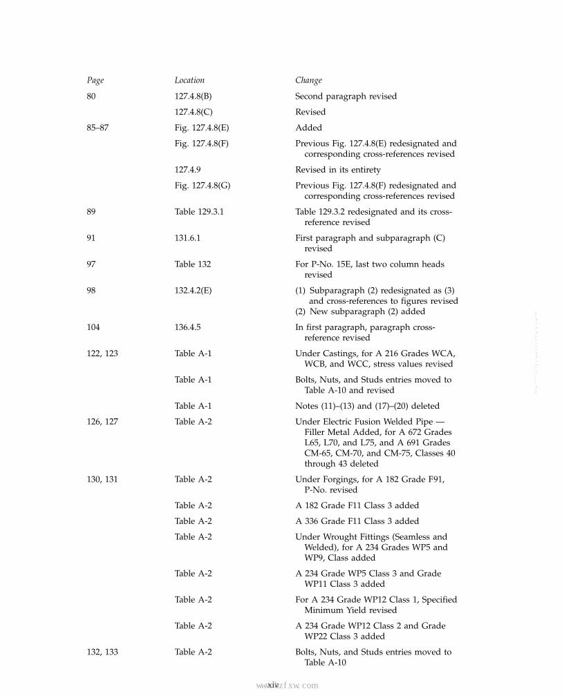
Page Location Change
xi, xii Introduction (1) In second paragraph, B31.12 added(2) Eighth-to-last and third-to-last
paragraphs revised
3 Fig. 100.1.2(A.2) Revised
6–8 100.2 Definitions of integrally reinforced branchoutlet fitting and owner added
16 Table 102.4.3 (1) Under Examination, third throughseventh entries revised
(2) Note (2) revised
17 102.4.6(B.1) First three paragraphs revised
18 102.4.6(B.2) First and fourth paragraphs revised
21 104.1.4 Equation (12) [formerly (14A)] revised
22 104.3.1(B.2) Revised
35 107.1(A) Revised
107.1(B) Revised
107.2 Revised
47 121.1 Revised
70 Table 126.1 (1) Under Castings, ASTM A 48M added(2) Under Cast Pipe, ASTM A 426M and
A 451M added(3) Under Seamless Pipe and Tube,
ASTM A 106M added
71 Table 126.1 (1) Under Welded Pipe and Tube, ASTMA 135M, A 139M, A 178M, andA 928M added
(2) Under Fittings, ASTM A 815M added(3) Under Structural Components, ASTM
A 992M added
73 Table 126.1 Under Welded Pipe and Tube, ASTMB 547M added
74 Table 126.1 (1) ASTM Standard Test Methodsheading and entries added
(2) Under MSS Standard Practices, titlesof SP-9, SP-43, SP-54, SP-55, SP-58,SP-61, SP-69, SP-80, and SP-94 revised
xiii
Copyright ASME International Provided by IHS under license with ASME No reproduction or networking permitted without license from IHS
--`,,```````,,```,`,`,,,,`,`,`,`-`-`,,`,,`,`,,`---
www.bzfxw.com
Page Location Change
80 127.4.8(B) Second paragraph revised
127.4.8(C) Revised
85–87 Fig. 127.4.8(E) Added
Fig. 127.4.8(F) Previous Fig. 127.4.8(E) redesignated andcorresponding cross-references revised
127.4.9 Revised in its entirety
Fig. 127.4.8(G) Previous Fig. 127.4.8(F) redesignated andcorresponding cross-references revised
89 Table 129.3.1 Table 129.3.2 redesignated and its cross-reference revised
91 131.6.1 First paragraph and subparagraph (C)revised
97 Table 132 For P-No. 15E, last two column headsrevised
98 132.4.2(E) (1) Subparagraph (2) redesignated as (3)and cross-references to figures revised
(2) New subparagraph (2) added
104 136.4.5 In first paragraph, paragraph cross-reference revised
122, 123 Table A-1 Under Castings, for A 216 Grades WCA,WCB, and WCC, stress values revised
Table A-1 Bolts, Nuts, and Studs entries moved toTable A-10 and revised
Table A-1 Notes (11)–(13) and (17)–(20) deleted
126, 127 Table A-2 Under Electric Fusion Welded Pipe —Filler Metal Added, for A 672 GradesL65, L70, and L75, and A 691 GradesCM-65, CM-70, and CM-75, Classes 40through 43 deleted
130, 131 Table A-2 Under Forgings, for A 182 Grade F91,P-No. revised
Table A-2 A 182 Grade F11 Class 3 added
Table A-2 A 336 Grade F11 Class 3 added
Table A-2 Under Wrought Fittings (Seamless andWelded), for A 234 Grades WP5 andWP9, Class added
Table A-2 A 234 Grade WP5 Class 3 and GradeWP11 Class 3 added
Table A-2 For A 234 Grade WP12 Class 1, SpecifiedMinimum Yield revised
Table A-2 A 234 Grade WP12 Class 2 and GradeWP22 Class 3 added
132, 133 Table A-2 Bolts, Nuts, and Studs entries moved toTable A-10
xiv
Copyright ASME International Provided by IHS under license with ASME No reproduction or networking permitted without license from IHS
--`,,```````,,```,`,`,,,,`,`,`,`-`-`,,`,,`,`,,`---
标准分享网 www.bzfxw.com 免费下载

www.bzfxw.com
Page Location Change
Table A-2 Note (6) revised
Table A-2 Notes (8)–(10), (13)–(16), and (18) deleted
158, 159 Table A-3 Bolts, Nuts, and Studs entries moved toTable A-10 and revised
162, 163 Table A-3 Notes (16)–(24) and (28) deleted
Table A-3 Note (39) redesignated as (32) andcorresponding cross-references revised
172, 173 Table A-4 Under Seamless Fittings, for both B 366N06022 lines, Nominal Compositionrevised; for first line, stress valuesrevised
Table A-4 For B 366 N06625, stress values revised
Table A-4 For both B 366 N08367 lines, NominalComposition and Notes revised
Table A-4 Both B 366 N08925 lines added
Table A-4 For both B 366 N08926 lines, NominalComposition revised
Table A-4 For both B 462 N08367 lines, NominalComposition revised
Table A-4 (1) Under Welded Fittings, all linesreferencing Note (13) added
(2) In previous lines for B 366 N06022,N08367, N08925, and N08926,Nominal Composition revised
(3) In previous lines for B 366 N06625and N08020, stress values revised
174 Table A-4 Note (13) added
178, 179 Table A-6 Under Seamless Pipe and Tube, for B 43C23000 Drawn, Specified MinimumTensile revised
Table A-6 For B 111 C44300, C44400, and C44500,stress value for 350°F italicized
Table A-6 For B 111 C68700, stress values at 350°Fthrough 450°F changed to roman
Table A-6 For B 111 C70400 Light drawn, stressvalues revised
Table A-6 For B 111 C71000, stress value at 550°Fchanged to roman
Table A-6 For B 111 C71500, stress values at 500°Fthrough 700°F changed to roman
Table A-6 For B 280 C12200 Annealed, stress valuesat 350°F and 400°F italicized
Table A-6 For B 302 C12000 and C12200, P-No.revised
xv
Copyright ASME International Provided by IHS under license with ASME No reproduction or networking permitted without license from IHS
--`,,```````,,```,`,`,,,,`,`,`,`-`-`,,`,,`,`,,`---

www.bzfxw.com
Page Location Change
Table A-6 For B 466 C71500, stress values at 500°Fthrough 700°F changed to roman
Table A-6 Under Welded Pipe and Tube, for allB 467 lines, stress values changed toroman
180, 181 Table A-6 Under Plate, for both B 171 C71500 lines,stress values at 500°F through 700°Fchanged to roman
Table A-6 Under Rod and Bar, for B 151 C71500,stress values at 500°F through 700°Fchanged to roman
Table A-6 Under Castings, for B 61 C92200, stressvalue at 500°F revised
Table A-6 For B 148 C95400 and B 584 C92200,stress value at 550°F revised
Table A-6 For B 584 C93700, stress values at −20°Fthrough 250°F revised
Table A-6 Bolts, Nuts, and Studs entries moved toTable A-10 and revised
182, 183 Table A-7 Under Drawn Seamless Tube, for B 210A93003 O, stress values at 250°F and300°F changed to roman
Table A-7 For B 210 A93003 H14, stress values at250°F through 350°F changed to romanand value at 400°F revised
Table A-7 For B 210 Alclad A93003 O, stress valuesat 250°F through 400°F changed toroman
Table A-7 For B 210 Alclad A93003 H14, stressvalues revised
Table A-7 For B 210 A96061 T4 and T6 welded,stress values for −20°F through 300°Frevised
Table A-7 Under Seamless Pipe and SeamlessExtruded Tube, for B 241 A93003 O,stress values at 250°F and 300°Fchanged to roman
Table A-7 For B 241 A93003 H18, stress values at250°F through 350°F changed to roman
Table A-7 For B 241 A93003 H112, stress values at250°F and 300°F changed to roman
Table A-7 For both B 241 Alclad A93003 lines, stressvalues at 250°F through 400°F changedto roman
Table A-7 For B 241 A96061 T4, stress values at350°F and 400°F italicized
xvi
Copyright ASME International Provided by IHS under license with ASME No reproduction or networking permitted without license from IHS
--`,,```````,,```,`,`,,,,`,`,`,`-`-`,,`,,`,`,,`---
标准分享网 www.bzfxw.com 免费下载

www.bzfxw.com
Page Location Change
Table A-7 For first B 241 A96061 T6 line, stressvalues at 250°F and 300°F changed toroman
Table A-7 For B 241 A96061 T4 and T6 welded,stress values at −20°F through 300°Frevised
Table A-7 For B 241 A96063 T6, stress values at250°F and 300°F revised
Table A-7 Under Drawn Seamless Condenser andHeat Exchanger Tube, for B 234 AlcladA93003 and last B 234 A96061 line,stress values revised
Table A-7 Under Arc-Welded Round Tube, for firstB 547 A93003 H112 line, stress valuesat 250°F through 350°F changed toroman
Table A-7 For all B 547 Alclad A93003 lines, stressvalues changed to roman
184, 185 Table A-7 For all B 547 A96061 T6 and T651 lines,stress value at 300°F changed to roman
Table A-7 Under Sheet and Plate, for B 209 A93003O, stress values at 250°F and 300°Fchanged to roman
Table A-7 For first B 209 A93003 H112 line, stressvalues at 250°F through 350°F changedto roman
Table A-7 For second B 209 A93003 H112 line,stress values revised
Table A-7 For first B 209 Alclad A93003 O line,stress values changed to roman
Table A-7 For second B 209 Alclad A93003 O lineand both Alclad A93003 H112 lines,stress values revised
Table A-7 For B 209 A96061 T4 and T451, stressvalues at 250°F and 300°F changed toroman
Table A-7 For B 209 A96061 T4 welded and T451welded, stress values revised
Table A-7 For B 209 A96061 T6 and first T651 line,stress values at 250°F and 300°Fchanged to roman
Table A-7 For second B 209 A96061 T651 line, stressvalues at 250°F and 300°F changed toroman, and stress value at 400°Frevised
Table A-7 For B 209 A96061 T6 welded and T651welded, stress values revised
xvii
Copyright ASME International Provided by IHS under license with ASME No reproduction or networking permitted without license from IHS
--`,,```````,,```,`,`,,,,`,`,`,`-`-`,,`,,`,`,,`---

www.bzfxw.com
Page Location Change
Table A-7 Under Die and Hand Forgings, for bothB 247 A93003 lines, stress values at250°F and 300°F changed to roman
186, 187 Table A-7 For B 247 A95083 H111, SpecifiedMinimum Yield revised
Table A-7 For all B 247 A96061 T6 lines, stressvalues at 250°F and 300°F changed toroman
Table A-7 For B 247 A96061 T6 welded, stressvalues revised
Table A-7 Under Rods, Bars, and Shapes, for bothB 221 A91060 lines, stress values at250°F and 300°F changed to roman
Table A-7 For both B 221 A91100 lines, stress valuesat 250°F through 350°F changed toroman
Table A-7 For both B 221 A93003 lines, stress valuesat 250°F and 300°F changed to roman
Table A-7 For all B 221 A92024 lines, stress value at250°F changed to roman
Table A-7 For B 221 A96061 T4 and T6, stressvalues at 250°F and 300°F changed toroman
Table A-7 For B 221 A96061 T4 welded and T6welded, stress values revised
188, 189 Table A-7 For first B 221 A96063 T1 line, stressvalue at 350°F italicized
Table A-7 For second B 221 A96063 T1 line, both T5lines, and T6 line, stress values at250°F and 300°F changed to roman
Table A-7 For B 221 A96063 T5 and T6 welded,stress values revised
Table A-7 Under Castings, for all lines, stress valueschanged to roman
200–204 Table A-10 Added
227–230 Mandatory Appendix F (1) ASTM Specifications updated(2) All ASTM Standard Test Methods
updated(3) MSS Standard Practices updated(4) AWS A3.0 and QC1 updated(5) Both PFI Standards updated(6) In list of organizations, information
added, and PFI and PPI informationrevised
xviii
Copyright ASME International Provided by IHS under license with ASME No reproduction or networking permitted without license from IHS
--`,,```````,,```,`,`,,,,`,`,`,`-`-`,,`,,`,`,,`---
标准分享网 www.bzfxw.com 免费下载

www.bzfxw.com
Page Location Change
231, 235 Mandatory Appendix G For tc and tn, references to Fig. 127.4.8(E)added
284–293 Nonmandatory Paragraphs and figures redesignatedAppendix V
SPECIAL NOTE:
The Interpretations to ASME B31.1 issued between January 1, 2009 and December 31, 2009 followthe last page of this Edition as a separate supplement, Interpretations Volume 45. After theInterpretations, a separate supplement, Cases No. 35, follows.
xix
Copyright ASME International Provided by IHS under license with ASME No reproduction or networking permitted without license from IHS
--`,,```````,,```,`,`,,,,`,`,`,`-`-`,,`,,`,`,,`---

www.bzfxw.comINTENTIONALLY LEFT BLANK
xx
Copyright ASME International Provided by IHS under license with ASME No reproduction or networking permitted without license from IHS
--`,,```````,,```,`,`,,,,`,`,`,`-`-`,,`,,`,`,,`---
标准分享网 www.bzfxw.com 免费下载

www.bzfxw.com
ASME B31.1-2010
POWER PIPING
Chapter IScope and Definitions
100 GENERAL
This Power Piping Code is one of several Sections ofthe American Society of Mechanical Engineers Code forPressure Piping, B31. This Section is published as a sepa-rate document for convenience.
Standards and specifications specifically incorporatedby reference into this Code are shown in Table 126.1. Itis not considered practical to refer to a dated edition ofeach of the standards and specifications in this Code.Instead, the dated edition references are included in anAddenda and will be revised yearly.
100.1 Scope
Rules for this Code Section have been developed con-sidering the needs for applications that include pipingtypically found in electric power generating stations, inindustrial and institutional plants, geothermal heatingsystems, and central and district heating and coolingsystems.
100.1.1 This Code prescribes requirements for thedesign, materials, fabrication, erection, test, inspection,operation, and maintenance of piping systems.
Piping as used in this Code includes pipe, flanges,bolting, gaskets, valves, relief devices, fittings, and thepressure containing portions of other piping compo-nents, whether manufactured in accordance withStandards listed in Table 126.1 or specially designed. Italso includes hangers and supports and other equipmentitems necessary to prevent overstressing the pressurecontaining components.
Rules governing piping for miscellaneous appurte-nances, such as water columns, remote water level indi-cators, pressure gages, gage glasses, etc., are includedwithin the scope of this Code, but the requirements forboiler appurtenances shall be in accordance withSection I of the ASME Boiler and Pressure Vessel Code,PG-60.
The users of this Code are advised that in some areaslegislation may establish governmental jurisdiction overthe subject matter covered by this Code. However, anysuch legal requirement shall not relieve the owner ofhis inspection responsibilities specified in para. 136.1.
1
100.1.2 Power piping systems as covered by thisCode apply to all piping and their component partsexcept as excluded in para. 100.1.3. They include butare not limited to steam, water, oil, gas, and air services.
(A) This Code covers boiler external piping as definedbelow for power boilers and high temperature, highpressure water boilers in which steam or vapor is gener-ated at a pressure of more than 15 psig [100 kPa (gage)];and high temperature water is generated at pressuresexceeding 160 psig [1 103 kPa (gage)] and/or tempera-tures exceeding 250°F (120°C).
Boiler external piping shall be considered as pipingthat begins where the boiler proper terminates at
(1) the first circumferential joint for welding endconnections; or
(2) the face of the first flange in bolted flangedconnections; or
(3) the first threaded joint in that type of connec-tion; and that extends up to and including the valve orvalves required by para. 122.1.
The terminal points themselves are considered part ofthe boiler external piping. The terminal points and pip-ing external to power boilers are illustrated byFigs. 100.1.2(A.1), 100.1.2(A.2), 100.1.2(B), and100.1.2(C).
Piping between the terminal points and the valve orvalves required by para. 122.1 shall be provided withData Reports, inspection, and stamping as required bySection I of the ASME Boiler and Pressure Vessel Code.All welding and brazing of this piping shall be per-formed by manufacturers or contractors authorized touse the appropriate symbol shown in Figs. PG-105.1through PG-105.3 of Section I of the ASME Boiler andPressure Vessel Code. The installation of boiler externalpiping by mechanical means may be performed by anorganization not holding a Code symbol stamp. How-ever, the holder of a valid S, A, or PP Certificate ofAuthorization shall be responsible for the documenta-tion and hydrostatic test, regardless of the method ofassembly. The quality control system requirements ofSection I of the ASME Boiler and Pressure Vessel Codeshall apply. These requirements are shown in Appendix Jof this Code.
Copyright ASME International Provided by IHS under license with ASME No reproduction or networking permitted without license from IHS
--`,,```````,,```,`,`,,,,`,`,`,`-`-`,,`,,`,`,,`---

www.bzfxw.com
ASME B31.1-2010
Fig. 100.1.2(A.1) Code Jurisdictional Limits for Piping — An Example of Forced Flow Steam Generators WithNo Fixed Steam and Water Line
Condenser
From feedpumps
Alternativespara. 122.1.7(B.9)
Administrative Jurisdiction and Technical Responsibility
Para. 122.1.7(B)
Start-up systemmay vary to suitboiler manufacturer
Economizer
Convectionand radiantsection
Reheater
Superheater
Turbine valve orCode stop valvepara. 122.1.7(A)
Turbine
To equipment
Boiler Proper — The ASME Boiler and Pressure Vessel Code (ASME BPVC) has total administrative jurisdiction and technical responsibility. Refer to ASME BPVC Section I Preamble.
Boiler External Piping and Joint (BEP) — The ASME BPVC has total administrative jurisdiction (mandatory certification by Code Symbol stamping, ASME Data Forms, and Authorized Inspection) of BEP. The ASME Section Committee B31.1 has been assigned technical responsibility. Refer to ASME BPVC Section I Preamble, fifth, sixth, and seventh paragraphs and ASME B31.1 Scope, para. 100.1.2(A). Applicable ASME B31.1 Editions and Addenda are referenced in ASME BPVC Section I, PG-58.3.
Nonboiler External Piping and Joint (NBEP) — The ASME Code Committee for Pressure Piping, B31, has total administrative and technical responsibility.
2
Copyright ASME International Provided by IHS under license with ASME No reproduction or networking permitted without license from IHS
--`,,```````,,```,`,`,,,,`,`,`,`-`-`,,`,,`,`,,`---标准分享网 www.bzfxw.com 免费下载

www.bzfxw.com
ASME B31.1-2010
(10)Fig. 100.1.2(A.2) Code Jurisdictional Limits for Piping — An Example of Steam Separator Type Forced FlowSteam Generators With No Fixed Steam and Water Line
Boiler feed pump
Alternatives para. 122.1.7(B.9)
Para. 122.1.7(B)(if used) (if used)
(if used)
Water
collector
Recirculation pump
(if used)
Steam
separator
Superheater
Reheater
Turbine
To equipment
Economizer
Convection
and radiant
section
Start-up system
may vary to suit
boiler manufacturer
Turbine valve or Code
stop valve para. 122.1.7(A)
Administrative Jurisdiction and Technical Responsibility
Boiler Proper – The ASME Boiler and Pressure Vessel Code (ASME BPVC) has total
administrative jurisdiction and technical responsibility. Refer to ASME BPVC Section I Preamble.
Boiler External Piping and Joint (BEP) – The ASME BPVC has total administrative jurisdiction
(mandatory certification by Code Symbol stamping, ASME Data Forms, and Authorized
Inspection) of BEP. The ASME Section Committee B31.1 has been assigned technical
responsibility. Refer to ASME BPVC Section I Preamble, fifth, sixth, and seventh paragraphs
and ASME B31.1 Scope, para. 100.1.2(A). Applicable ASME B31.1 Editions and Addenda are
referenced in ASME BPVC Section I, PG-58.3.
Nonboiler External Piping and Joint (NBEP) – The ASME Code Committee for Pressure Piping,
B31, has total administrative and technical responsibility.
3
Copyright ASME International Provided by IHS under license with ASME No reproduction or networking permitted without license from IHS
--`,,```````,,```,`,`,,,,`,`,`,`-`-`,,`,,`,`,,`---

www.bzfxw.com
ASME B31.1-2010
Fig. 100.1.2(B) Code Jurisdictional Limits for Piping — Drum-Type Boilers
Blow-off single and multiple installations
Feedwater systems and valving 122.1.3 & 122.1.7
Drain
Drain Drain122.1.5
Soot blowers
Level indicators 122.1.6
122.1.4
Main steam 122.1.2
122.6.2
Vents and instrumentation
Drain
Single installation
Multiple installation
Common header
Control device 122.1.6
Vent
Drain
Inlet header (if used)
Superheater
Reheater
Economizer
Drain
122.1.7(D) Hot reheat
122.1.7(D) Cold reheat
Vent
Vent
Drain
122.1.2
Steam drum
Soot blowers
Surface blowContinuous blowChemical feed drum sample
Multiple installations
Single installation
Common header
Single boiler
Single boiler
Two or more boilers fed from a common source
Two or more boilers fed from a common source
Regulating valves
Boiler No. 2
Boiler No. 1
Boiler No. 2
Boiler No. 1
Vent
Vent
122.1.4 Water drum
Administrative Jurisdiction and Technical Responsibility
Boiler Proper — The ASME Boiler and Pressure Vessel Code (ASME BPVC) has total administrative jurisdiction and technical responsibility. Refer to ASME BPVC Section I Preamble.
Boiler External Piping and Joint (BEP) — The ASME BPVC has total administrative jurisdiction (mandatory certification by Code Symbol stamping, ASME Data Forms, and Authorized Inspection) of BEP. The ASME Section Committee B31.1 has been assigned technical responsibility. Refer to ASME BPVC Section I Preamble and ASME B31.1 Scope, para. 100.1.2(A). Applicable ASME B31.1 Editions and Addenda are referenced in ASME BPVC Section I, PG-58.3.
Nonboiler External Piping and Joint (NBEP) — The ASME Code Committee for Pressure Piping, B31, has total administrative jurisdiction and technical responsibility.
4
Copyright ASME International Provided by IHS under license with ASME No reproduction or networking permitted without license from IHS
--`,,```````,,```,`,`,,,,`,`,`,`-`-`,,`,,`,`,,`---标准分享网 www.bzfxw.com 免费下载

www.bzfxw.com
ASME B31.1-2010
Fig. 100.1.2(C) Code Jurisdictional Limits for Piping — Spray-Type Desuperheater
Regulating valvepara. 122.4(A.1)
Regulating valvepara. 122.4(A.1)
Stop valvepara. 122.4(A.1)
Stop valvepara. 122.4(A.1)
Administrative Jurisdiction and Technical Responsibility
Desuperheaterlocated in boilerproper
Block valvepara. 122.4(A.1)
Block valvepara. 122.4(A.1)
Boiler Proper — The ASME Boiler and Pressure Vessel Code (ASME BPVC) has total administrative jurisdiction and technical responsibility. Refer to ASME BPVC Section 1 Preamble.
Boiler External Piping and Joint (BEP) — The ASME BPVC has total administrative jurisdiction (mandatory certification by Code Symbol stamping, ASME Data Forms, and Authorized Inspection) of BEP. The ASME Section Committee B31.1 has been assigned technical responsibility. Refer to ASME BPVC Section I Preamble and ASME B31.1 Scope, para. 100.1.2(A). Applicable ASME B31.1 Editions and Addenda are referenced in ASME BPVC Section I, PG-58.3.
Nonboiler External Piping and Joint (NBEP) — The ASME Code Committee for Pressure Piping, B31, has total administrative and technical responsibility.
Desuperheaterlocated in boilerproper
5
Copyright ASME International Provided by IHS under license with ASME No reproduction or networking permitted without license from IHS
--`,,```````,,```,`,`,,,,`,`,`,`-`-`,,`,,`,`,,`---

www.bzfxw.com(10)
ASME B31.1-2010
The valve or valves required by para. 122.1 are partof the boiler external piping, but do not require ASMEBoiler and Pressure Vessel Code, Section I inspectionand stamping except for safety, safety relief, and reliefvalves; see para. 107.8.2. Refer to PG-11.
Pipe connections meeting all other requirements ofthis Code but not exceeding NPS 1⁄2 may be welded topipe or boiler headers without inspection and stampingrequired by Section I of the ASME Boiler and PressureVessel Code.
(B) Nonboiler external piping includes all the pipingcovered by this Code except for that portion definedabove as boiler external piping.
100.1.3 This Code does not apply to the following:(A) economizers, heaters, pressure vessels, and
components covered by Sections of the ASME Boilerand Pressure Vessel Code
(B) building heating and distribution steam and con-densate piping designed for 15 psig [100 kPa (gage)] orless, or hot water heating systems designed for 30 psig[200 kPa (gage)] or less
(C) piping for hydraulic or pneumatic tools and theircomponents downstream of the first block or stop valveoff the system distribution header
(D) piping for marine or other installations underFederal control
(E) towers, building frames, tanks, mechanical equip-ment, instruments, and foundations
100.2 Definitions
Some commonly used terms relating to piping aredefined below. Terms related to welding generally agreewith AWS A3.0. Some welding terms are defined withspecified reference to piping. For welding terms used inthis Code, but not shown here, definitions of AWS A3.0apply.
anchor: a rigid restraint providing substantially full fixa-tion, permitting neither translatory nor rotational dis-placement of the pipe.
annealing: see heat treatments.
arc welding: a group of welding processes wherein coales-cence is produced by heating with an electric arc or arcs,with or without the application of pressure and with orwithout the use of filler metal.
assembly: the joining together of two or more pipingcomponents by bolting, welding, caulking, brazing, sol-dering, cementing, or threading into their installed loca-tion as specified by the engineering design.
automatic welding: welding with equipment that per-forms the entire welding operation without constantobservation and adjustment of the controls by an opera-tor. The equipment may or may not perform the loadingand unloading of the work.
6
backing ring: backing in the form of a ring that can beused in the welding of piping.ball joint: a component that permits universal rotationalmovement in a piping system.base metal: the metal to be welded, brazed, soldered,or cut.branch connection: the attachment of a branch pipe to therun of a main pipe with or without the use of fittings.braze welding: a method of welding whereby a groove,fillet, plug, or slot weld is made using a nonferrous fillermetal having a melting point below that of the basemetals, but above 840°F (450°C). The filler metal is notdistributed in the joint by capillary action. (Bronze weld-ing, formerly used, is a misnomer for this term.)brazing: a metal joining process wherein coalescence isproduced by use of a nonferrous filler metal having amelting point above 840°F (450°C) but lower than thatof the base metals joined. The filler metal is distributedbetween the closely fitted surfaces of the joint by capil-lary action.butt joint: a joint between two members lying approxi-mately in the same plane.capacitor discharge welding (CDW): stud arc welding pro-cess in which DC arc power is produced by a rapiddischarge of stored electrical energy with pressureapplied during or immediately following the electricaldischarge. The process uses an electrostatic storage sys-tem as a power source in which the weld energy is storedin capacitors.component: component as used in this Code is definedas consisting of but not limited to items such as pipe,piping subassemblies, parts, valves, strainers, reliefdevices, fittings, etc.
specially designed component: a component designed inaccordance with para. 104.7.2.
standard component: a component manufactured inaccordance with one or more of the standards listed inTable 126.1.covered piping systems (CPS): piping systems on whichcondition assessments are to be conducted. As a mini-mum for electric power generating stations, the CPSsystems are to include NPS 4 and larger of the mainsteam, hot reheat steam, cold reheat steam, and boilerfeedwater piping systems. In addition to the above, CPSalso includes NPS 4 and larger piping in other systemsthat operate above 750°F (400°C) or above 1,025 psi(7 100 kPa). The Operating Company may, in its judg-ment, include other piping systems determined to behazardous by an engineering evaluation of probabilityand consequences of failure.creep strength enhanced ferritic steel: steel in which themicrostructure, consisting of lower transformation prod-ucts such as martensite and bainite, is stabilized bycontrolled precipitation of temper-resistant carbides,carbonitrides, and/or nitrides.
Copyright ASME International Provided by IHS under license with ASME No reproduction or networking permitted without license from IHS
--`,,```````,,```,`,`,,,,`,`,`,`-`-`,,`,,`,`,,`---
标准分享网 www.bzfxw.com 免费下载

www.bzfxw.com
ASME B31.1-2010
defect: a flaw (imperfection or unintentional discontinu-ity) of such size, shape, orientation, location, or proper-ties as to be rejectable.
discontinuity: a lack of continuity or cohesion; an inter-ruption in the normal physical structure of material ora product.
employer: the owner, manufacturer, fabricator, contractor,assembler, or installer responsible for the welding, braz-ing, and NDE performed by his organization includingprocedure and performance qualifications.
engineering design: the detailed design developed fromprocess requirements and conforming to Code require-ments, including all necessary drawings and specifica-tions, governing a piping installation.
equipment connection: an integral part of such equipmentas pressure vessels, heat exchangers, pumps, etc.,designed for attachment of pipe or piping components.
erection: the complete installation of a piping system,including any field assembly, fabrication, testing, andinspection of the system.
examination: denotes the procedures for all nondestruc-tive examination. Refer to para. 136.3 and the definitionfor visual examination.
expansion joint: a flexible piping component that absorbsthermal and/or terminal movement.
fabrication: primarily, the joining of piping componentsinto integral pieces ready for assembly. It includes bend-ing, forming, threading, welding, or other operationsupon these components, if not part of assembly. It maybe done in a shop or in the field.
face of weld: the exposed surface of a weld on the sidefrom which the welding was done.
filler metal: metal to be added in welding, soldering,brazing, or braze welding.
fillet weld: a weld of approximately triangular cross sec-tion joining two surfaces approximately at right anglesto each other in a lap joint, tee joint, corner joint, orsocket weld.
fire hazard: situation in which a material of more thanaverage combustibility or explosibility exists in the pres-ence of a potential ignition source.
flaw: an imperfection or unintentional discontinuity thatis detectable by a nondestructive examination.
full fillet weld: a fillet weld whose size is equal to thethickness of the thinner member joined.
fusion: the melting together of filler metal and base metal,or of base metal only, that results in coalescence.
gas welding: a group of welding processes whereincoalescence is produced by heating with a gas flame orflames, with or without the application of pressure, andwith or without the use of filler metal.
7
groove weld: a weld made in the groove between twomembers to be joined.
heat affected zone: portion of the base metal that has notbeen melted, but whose mechanical properties or micro-structure have been altered by the heat of welding orcutting.
heat treatmentsannealing, full: heating a metal or alloy to a tempera-
ture above the critical temperature range and holdingabove the range for a proper period of time, followedby cooling to below that range. (A softening treatmentis often carried out just below the critical range, whichis referred to as a subcritical anneal.)
normalizing: a process in which a ferrous metal isheated to a suitable temperature above the transforma-tion range and is subsequently cooled in still air at roomtemperature.
postweld heat treatment: any heat treatment subsequentto welding.
preheating: the application of heat to a base metalimmediately prior to a welding or cutting operation.
stress-relieving: uniform heating of a structure or por-tion thereof to a sufficient temperature to relieve themajor portion of the residual stresses, followed by uni-form cooling.
imperfection: a condition of being imperfect; a departureof a quality characteristic from its intended condition.
indication: the response or evidence from the applicationof a nondestructive examination.
inert gas metal arc welding: an arc welding processwherein coalescence is produced by heating with anelectric arc between a metal electrode and the work.Shielding is obtained from an inert gas, such as heliumor argon. Pressure may or may not be used and fillermetal may or may not be used.
inspection: denotes the activities performed by anAuthorized Inspector, or an Owner’s Inspector, to verifythat all required examinations and testing have beencompleted, and to ensure that all the documentation formaterial, fabrication, and examination conforms to theapplicable requirements of this Code and the engi-neering design.
integrally reinforced branch outlet fitting: a branch outletfitting that is welded directly to a run pipe, where thebranch fitting and the deposited weld metal used toattach the fitting to the run pipe are designed by thefitting manufacturer to provide all the reinforcementrequired by this Code without the addition of separatesaddles or pads. The attachment of the branch pipe tothe fitting is by butt welding, socket welding, threading,or by a flanged connection. Integrally reinforced branchoutlet fittings include those fittings conforming toMSS SP-97.
Copyright ASME International Provided by IHS under license with ASME No reproduction or networking permitted without license from IHS
--`,,```````,,```,`,`,,,,`,`,`,`-`-`,,`,,`,`,,`---
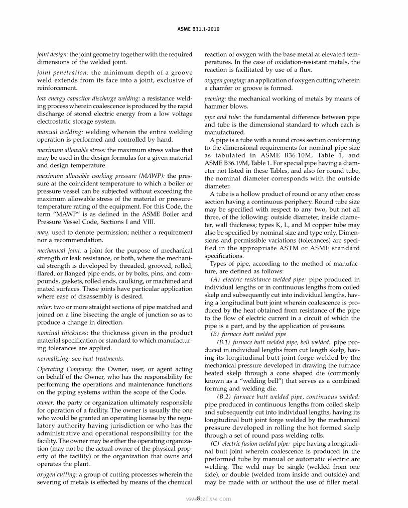
www.bzfxw.com
ASME B31.1-2010
joint design: the joint geometry together with the requireddimensions of the welded joint.
joint penetration: the minimum depth of a grooveweld extends from its face into a joint, exclusive ofreinforcement.
low energy capacitor discharge welding: a resistance weld-ing process wherein coalescence is produced by the rapiddischarge of stored electric energy from a low voltageelectrostatic storage system.
manual welding: welding wherein the entire weldingoperation is performed and controlled by hand.
maximum allowable stress: the maximum stress value thatmay be used in the design formulas for a given materialand design temperature.
maximum allowable working pressure (MAWP): the pres-sure at the coincident temperature to which a boiler orpressure vessel can be subjected without exceeding themaximum allowable stress of the material or pressure-temperature rating of the equipment. For this Code, theterm “MAWP” is as defined in the ASME Boiler andPressure Vessel Code, Sections I and VIII.
may: used to denote permission; neither a requirementnor a recommendation.
mechanical joint: a joint for the purpose of mechanicalstrength or leak resistance, or both, where the mechani-cal strength is developed by threaded, grooved, rolled,flared, or flanged pipe ends, or by bolts, pins, and com-pounds, gaskets, rolled ends, caulking, or machined andmated surfaces. These joints have particular applicationwhere ease of disassembly is desired.
miter: two or more straight sections of pipe matched andjoined on a line bisecting the angle of junction so as toproduce a change in direction.
nominal thickness: the thickness given in the productmaterial specification or standard to which manufactur-ing tolerances are applied.
normalizing: see heat treatments.
Operating Company: the Owner, user, or agent actingon behalf of the Owner, who has the responsibility forperforming the operations and maintenance functionson the piping systems within the scope of the Code.
owner: the party or organization ultimately responsiblefor operation of a facility. The owner is usually the onewho would be granted an operating license by the regu-latory authority having jurisdiction or who has theadministrative and operational responsibility for thefacility. The owner may be either the operating organiza-tion (may not be the actual owner of the physical prop-erty of the facility) or the organization that owns andoperates the plant.
oxygen cutting: a group of cutting processes wherein thesevering of metals is effected by means of the chemical
8
reaction of oxygen with the base metal at elevated tem-peratures. In the case of oxidation-resistant metals, thereaction is facilitated by use of a flux.
oxygen gouging: an application of oxygen cutting whereina chamfer or groove is formed.
peening: the mechanical working of metals by means ofhammer blows.
pipe and tube: the fundamental difference between pipeand tube is the dimensional standard to which each ismanufactured.
A pipe is a tube with a round cross section conformingto the dimensional requirements for nominal pipe sizeas tabulated in ASME B36.10M, Table 1, andASME B36.19M, Table 1. For special pipe having a diam-eter not listed in these Tables, and also for round tube,the nominal diameter corresponds with the outsidediameter.
A tube is a hollow product of round or any other crosssection having a continuous periphery. Round tube sizemay be specified with respect to any two, but not allthree, of the following: outside diameter, inside diame-ter, wall thickness; types K, L, and M copper tube mayalso be specified by nominal size and type only. Dimen-sions and permissible variations (tolerances) are speci-fied in the appropriate ASTM or ASME standardspecifications.
Types of pipe, according to the method of manufac-ture, are defined as follows:
(A) electric resistance welded pipe: pipe produced inindividual lengths or in continuous lengths from coiledskelp and subsequently cut into individual lengths, hav-ing a longitudinal butt joint wherein coalescence is pro-duced by the heat obtained from resistance of the pipeto the flow of electric current in a circuit of which thepipe is a part, and by the application of pressure.
(B) furnace butt welded pipe(B.1) furnace butt welded pipe, bell welded: pipe pro-
duced in individual lengths from cut length skelp, hav-ing its longitudinal butt joint forge welded by themechanical pressure developed in drawing the furnaceheated skelp through a cone shaped die (commonlyknown as a “welding bell”) that serves as a combinedforming and welding die.
(B.2) furnace butt welded pipe, continuous welded:pipe produced in continuous lengths from coiled skelpand subsequently cut into individual lengths, having itslongitudinal butt joint forge welded by the mechanicalpressure developed in rolling the hot formed skelpthrough a set of round pass welding rolls.
(C) electric fusion welded pipe: pipe having a longitudi-nal butt joint wherein coalescence is produced in thepreformed tube by manual or automatic electric arcwelding. The weld may be single (welded from oneside), or double (welded from inside and outside) andmay be made with or without the use of filler metal.
Copyright ASME International Provided by IHS under license with ASME No reproduction or networking permitted without license from IHS
--`,,```````,,```,`,`,,,,`,`,`,`-`-`,,`,,`,`,,`---
标准分享网 www.bzfxw.com 免费下载

www.bzfxw.com
ASME B31.1-2010
Spiral welded pipe is also made by the electric fusionwelded process with either a butt joint, a lap joint, or alock seam joint.
(D) electric flash welded pipe: pipe having a longitudi-nal butt joint wherein coalescence is produced, simulta-neously over the entire area of abutting surfaces, bythe heat obtained from resistance to the flow of electriccurrent between the two surfaces, and by the applicationof pressure after heating is substantially completed.Flashing and upsetting are accompanied by expulsionof metal from the joint.
(E) double submerged arc welded pipe: pipe having alongitudinal butt joint produced by the submerged arcprocess, with at least two passes, one of which is on theinside of the pipe.
(F) seamless pipe: pipe produced by one or more ofthe following processes:
(F.1) rolled pipe: pipe produced from a forged billetthat is pierced by a conical mandrel between two diamet-rically opposed rolls. The pierced shell is subsequentlyrolled and expanded over mandrels of increasinglylarger diameter. Where closer dimensional tolerancesare desired, the rolled pipe is cold or hot drawn throughdies, and machined.
One variation of this process produces the hollow shellby extrusion of the forged billet over a mandrel in avertical, hydraulic piercing press.
(F.2) forged and bored pipe: pipe produced by boringor trepanning of a forged billet.
(F.3) extruded pipe: pipe produced from hollow orsolid round forgings, usually in a hydraulic extrusionpress. In this process the forging is contained in a cylin-drical die. Initially a punch at the end of the extrusionplunger pierces the forging. The extrusion plunger thenforces the contained billet between the cylindrical dieand the punch to form the pipe, the latter acting as amandrel.
(F.4) centrifugally cast pipe: pipe formed from thesolidification of molten metal in a rotating mold. Bothmetal and sand molds are used. After casting, the pipeis machined, to sound metal, on the internal and externaldiameters to the surface roughness and dimensionalrequirements of the applicable material specification.
One variation of this process utilizes autofrettage(hydraulic expansion) and heat treatment, above therecrystallization temperature of the material, to producea wrought structure.
(F.5) statically cast pipe: pipe formed by the solidifi-cation of molten metal in a sand mold.
pipe supporting elements: pipe supporting elements con-sist of hangers, supports, and structural attachments.
hangers and supports: hangers and supports includeelements that transfer the load from the pipe or struc-tural attachment to the supporting structure or equip-ment. They include hanging type fixtures, such as
9
hanger rods, spring hangers, sway braces, counter-weights, turnbuckles, struts, chains, guides, andanchors, and bearing type fixtures, such as saddles,bases, rollers, brackets, and sliding supports.
structural attachments: structural attachments includeelements that are welded, bolted, or clamped to the pipe,such as clips, lugs, rings, clamps, clevises, straps, andskirts.
porosity: cavity-type discontinuities formed by gasentrapment during metal solidification.
postweld heat treatment: see heat treatments.
preheating: see heat treatments.
pressure: an application of force per unit area; fluidpressure (an application of internal or external fluidforce per unit area on the pressure boundary of pipingcomponents).
Procedure Qualification Record (PQR): a record of the weld-ing data used to weld a test coupon. The PQR is a recordof variables recorded during the welding of the testcoupons. It also contains the test results of the testedspecimens. Recorded variables normally fall within asmall range of the actual variables that will be used inproduction welding.
readily accessible: for visual examination, readily accessi-ble inside surfaces are defined as those inside surfacesthat can be examined without the aid of optical devices.(This definition does not prohibit the use of opticaldevices for a visual examination; however, the selectionof the device should be a matter of mutual agreementbetween the owner and the fabricator or erector.)
Reid vapor pressure: the vapor pressure of a flammableor combustible liquid as determined by ASTM StandardTest Method D 323 Vapor Pressure of PetroleumProducts (Reid Method).
reinforcement of weld: weld metal on the face of a grooveweld in excess of the metal necessary for the specifiedweld size.
restraint: any device that prevents, resists, or limits move-ment of a piping system.
root opening: the separation between the members to bejoined, at the root of the joint.
root penetration: the depth a groove weld extends intothe root opening of a joint measured on the centerlineof the root cross section.
seal weld: a weld used on a pipe joint primarily to obtainfluid tightness as opposed to mechanical strength.
semiautomatic arc welding: arc welding with equipmentthat controls only the filler metal feed. The advance ofthe welding is manually controlled.
shall: “shall” or “shall not” is used to indicate that aprovision or prohibition is mandatory.
Copyright ASME International Provided by IHS under license with ASME No reproduction or networking permitted without license from IHS
--`,,```````,,```,`,`,,,,`,`,`,`-`-`,,`,,`,`,,`---

www.bzfxw.com
ASME B31.1-2010
shielded metal arc welding: an arc welding process whereincoalescence is produced by heating with an electric arcbetween a covered metal electrode and the work.Shielding is obtained from decomposition of the elec-trode covering. Pressure is not used and filler metal isobtained from the electrode.should: “should” or “it is recommended” is used to indi-cate that a provision is not mandatory but recommendedas good practice.size of weld
fillet weld: for equal leg fillet welds, the leg lengths ofthe largest isosceles right triangle that can be inscribedwithin the fillet weld cross section. For unequal leg filletwelds, the leg lengths of the largest right triangle thatcan be inscribed within the fillet weld cross section.
groove weld: the joint penetration (depth of chamferingplus the root penetration when specified).slag inclusion: nonmetallic solid material entrapped inweld metal or between weld metal and base metal.soldering: a metal joining process wherein coalescence isproduced by heating to suitable temperature and byusing a nonferrous alloy fusible at temperatures below840°F (450°C) and having a melting point below that ofthe base metals being joined. The filler metal is distrib-uted between closely fitted surfaces of the joint by capil-lary action. In general, solders are lead–tin alloys andmay contain antimony, bismuth, silver, and otherelements.steel: an alloy of iron and carbon with no more than 2%carbon by weight. Other alloying elements may includemanganese, sulfur, phosphorus, silicon, aluminum,chromium, copper, nickel, molybdenum, vanadium, andothers depending upon the type of steel. For acceptablematerial specifications for steel, refer to Chapter III,Materials.stresses
displacement stress: a stress developed by the self-constraint of the structure. It must satisfy an imposedstrain pattern rather than being in equilibrium with anexternal load. The basic characteristic of a displacementstress is that it is self-limiting. Local yielding and minordistortions can satisfy the displacement or expansionconditions that cause the stress to occur. Failure from oneapplication of the stress is not to be expected. Further,the displacement stresses calculated in this Code are“effective” stresses and are generally lower than thosepredicted by theory or measured in strain-gage tests.1
1 Normally, the most significant displacement stress is encoun-tered in the thermal expansion stress range from ambient to thenormal operating condition. This stress range is also the stressrange usually considered in a flexibility analysis. However, if othersignificant stress ranges occur, whether they are displacement stressranges (such as from other thermal expansion or contraction events,or differential support movements) or sustained stress ranges (suchas from cyclic pressure, steam hammer, or earthquake inertiaforces), paras. 102.3.2(B) and 104.8.3 may be used to evaluate theireffect on fatigue life.
10
peak stress: the highest stress in the region under con-sideration. The basic characteristic of a peak stress isthat it causes no significant distortion and is objection-able only as a possible source of a fatigue crack initiationor a brittle fracture. This Code does not utilize peakstress as a design basis, but rather uses effective stressvalues for sustained stress and for displacement stress;the peak stress effect is combined with the displacementstress effect in the displacement stress range calculation.
sustained stress: a stress developed by an imposed load-ing that is necessary to satisfy the laws of equilibriumbetween external and internal forces and moments. Thebasic characteristic of a sustained stress is that it is notself-limiting. If a sustained stress exceeds the yieldstrength of the material through the entire thickness, theprevention of failure is entirely dependent on the strain-hardening properties of the material. A thermal stress isnot classified as a sustained stress. Further, the sustainedstresses calculated in this Code are “effective” stressesand are generally lower than those predicted by theoryor measured in strain-gage tests.
stress-relieving: see heat treatments.
submerged arc welding: an arc welding process whereincoalescence is produced by heating with an electric arcor arcs between a bare metal electrode or electrodesand the work. The welding is shielded by a blanket ofgranular, fusible material on the work. Pressure is notused, and filler metal is obtained from the electrode andsometimes from a supplementary welding rod.
supplementary steel: steel members that are installedbetween existing members for the purpose of installingsupports for piping or piping equipment.
swivel joint: a component that permits single-plane rota-tional movement in a piping system.
tack weld: a weld made to hold parts of a weldment inproper alignment until the final welds are made.
throat of a fillet weldactual: the shortest distance from the root of a fillet
weld to its face.theoretical: the distance from the beginning of the root
of the joint perpendicular to the hypotenuse of the larg-est right triangle that can be inscribed within the filletweld cross section.
toe of weld: the junction between the face of the weldand the base metal.
tube: refer to pipe and tube.
tungsten electrode: a nonfiller metal electrode used in arcwelding, consisting of a tungsten wire.
undercut: a groove melted into the base metal adjacentto the toe of a weld and not filled with weld metal.
visual examination: the observation of whatever portionsof components, joints, and other piping elements thatare exposed to such observation either before, during,
Copyright ASME International Provided by IHS under license with ASME No reproduction or networking permitted without license from IHS
--`,,```````,,```,`,`,,,,`,`,`,`-`-`,,`,,`,`,,`---
标准分享网 www.bzfxw.com 免费下载
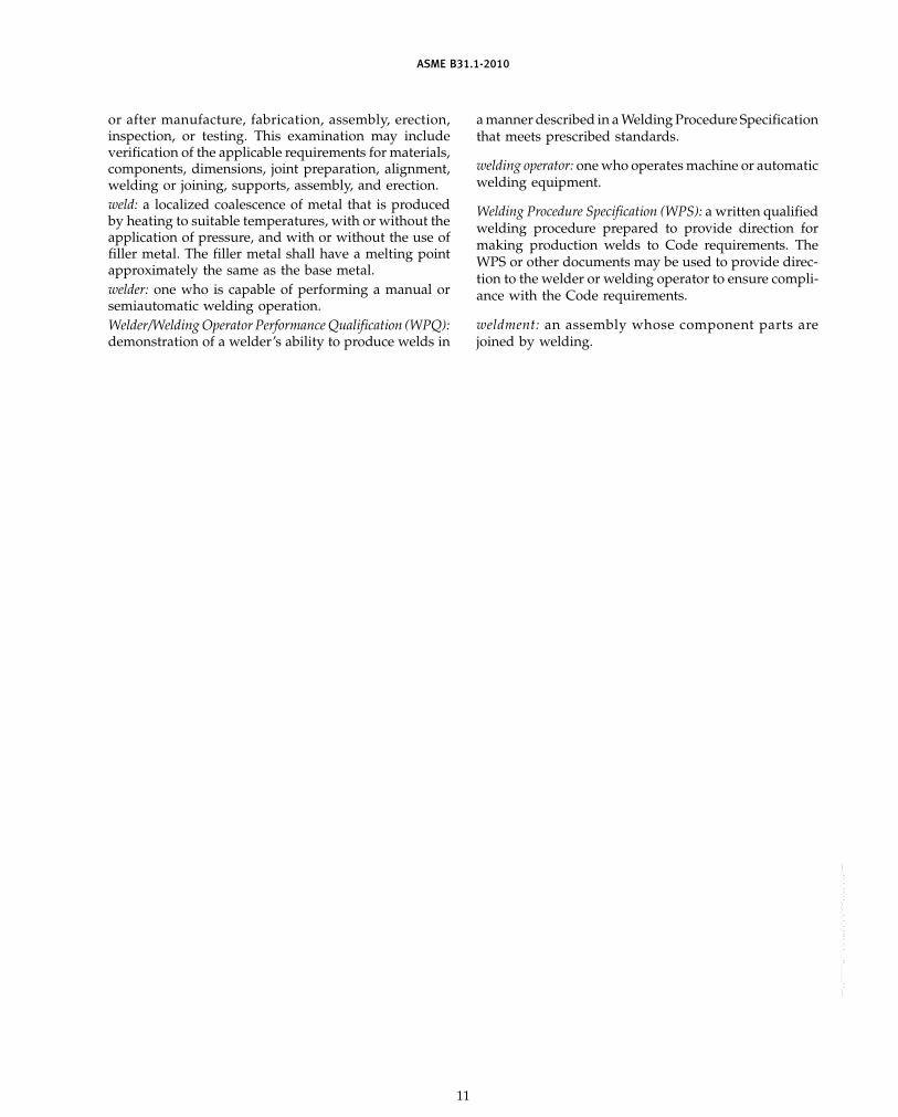
www.bzfxw.com
ASME B31.1-2010
or after manufacture, fabrication, assembly, erection,inspection, or testing. This examination may includeverification of the applicable requirements for materials,components, dimensions, joint preparation, alignment,welding or joining, supports, assembly, and erection.weld: a localized coalescence of metal that is producedby heating to suitable temperatures, with or without theapplication of pressure, and with or without the use offiller metal. The filler metal shall have a melting pointapproximately the same as the base metal.welder: one who is capable of performing a manual orsemiautomatic welding operation.Welder/Welding Operator Performance Qualification (WPQ):demonstration of a welder’s ability to produce welds in
11
a manner described in a Welding Procedure Specificationthat meets prescribed standards.
welding operator: one who operates machine or automaticwelding equipment.
Welding Procedure Specification (WPS): a written qualifiedwelding procedure prepared to provide direction formaking production welds to Code requirements. TheWPS or other documents may be used to provide direc-tion to the welder or welding operator to ensure compli-ance with the Code requirements.
weldment: an assembly whose component parts arejoined by welding.
Copyright ASME International Provided by IHS under license with ASME No reproduction or networking permitted without license from IHS
--`,,```````,,```,`,`,,,,`,`,`,`-`-`,,`,,`,`,,`---

www.bzfxw.com
ASME B31.1-2010
Chapter IIDesign
PART 1CONDITIONS AND CRITERIA
101 DESIGN CONDITIONS101.1 General
These design conditions define the pressures, temper-atures, and various forces applicable to the design ofpower piping systems. Power piping systems shall bedesigned for the most severe condition of coincidentpressure, temperature, and loading, except as hereinstated. The most severe condition shall be that whichresults in the greatest required pipe wall thickness andthe highest flange rating.
101.2 PressureAll pressures referred to in this Code are expressed in
pounds per square inch and kilopascals above atmo-spheric pressure, i.e., psig [kPa (gage)], unless otherwisestated.
101.2.2 Internal Design Pressure. The internaldesign pressure shall be not less than the maximumsustained operating pressure (MSOP) within the pipingsystem including the effects of static head.
101.2.4 External Design Pressure. Piping subject toexternal pressure shall be designed for the maximumdifferential pressure anticipated during operating, shut-down, or test conditions.
101.2.5 Pressure Cycling. This Code does notaddress the contribution to fatigue in fittings and com-ponents caused by pressure cycling. Special consider-ation may be necessary where systems are subjected toa very high number of large pressure cycles.
101.3 Temperature
101.3.1 All temperatures referred to in this Code,unless otherwise stated, are the average metal tempera-tures of the respective materials expressed in degreesFahrenheit, i.e., °F (Celsius, i.e., °C).
101.3.2 Design Temperature(A) The piping shall be designed for a metal tempera-
ture representing the maximum sustained conditionexpected. The design temperature shall be assumed tobe the same as the fluid temperature unless calculationsor tests support the use of other data, in which case thedesign temperature shall not be less than the average ofthe fluid temperature and the outside wall temperature.
(B) Where a fluid passes through heat exchangers inseries, the design temperature of the piping in each
12
section of the system shall conform to the most severetemperature condition expected to be produced by theheat exchangers in that section of the system.
(C) For steam, feedwater, and hot water piping lead-ing from fired equipment (such as boiler, reheater, super-heater, economizer, etc.), the design temperature shallbe based on the expected continuous operating condi-tion plus the equipment manufacturers guaranteed max-imum temperature tolerance. For operation attemperatures in excess of this condition, the limitationsdescribed in para. 102.2.4 shall apply.
(D) Accelerated creep damage, leading to excessivecreep strains and potential pipe rupture, caused byextended operation above the design temperature shallbe considered in selecting the design temperature forpiping to be operated above 800°F (425°C).
101.4 Ambient Influences101.4.1 Cooling Effects on Pressure. Where the
cooling of a fluid may reduce the pressure in the pipingto below atmospheric, the piping shall be designed towithstand the external pressure or provision shall bemade to break the vacuum.
101.4.2 Fluid Expansion Effects. Where the expan-sion of a fluid may increase the pressure, the pipingsystem shall be designed to withstand the increasedpressure or provision shall be made to relieve the excesspressure.
101.5 Dynamic Effects101.5.1 Impact. Impact forces caused by all external
and internal conditions shall be considered in the pipingdesign. One form of internal impact force is due to thepropagation of pressure waves produced by suddenchanges in fluid momentum. This phenomena is oftencalled water or steam “hammer.” It may be caused bythe rapid opening or closing of a valve in the system. Thedesigner should be aware that this is only one example ofthis phenomena and that other causes of impact load-ing exist.
101.5.2 Wind. Exposed piping shall be designed towithstand wind loadings. The analysis considerationsand loads may be as described in ASCE/SEI 7, MinimumDesign Loads for Buildings and Other Structures.Authoritative local meteorological data may also beused to define or refine the design wind forces. Wherelocal jurisdictional rules covering the design of buildingstructures are in effect and specify wind loadings forpiping, these values shall be considered the minimum
Copyright ASME International Provided by IHS under license with ASME No reproduction or networking permitted without license from IHS
--`,,```````,,```,`,`,,,,`,`,`,`-`-`,,`,,`,`,,`---
标准分享网 www.bzfxw.com 免费下载

www.bzfxw.com
ASME B31.1-2010
design values. Wind need not be considered as actingconcurrently with earthquakes.
101.5.3 Earthquake. The effect of earthquakes shallbe considered in the design of piping, piping supports,and restraints. The analysis considerations and loadsmay be as described in ASCE/SEI 7. Authoritative localseismological data may also be used to define or refinethe design earthquake forces. Where local jurisdictionalrules covering the design of building structures are ineffect and specify seismic loadings for piping, these val-ues shall be considered the minimum design values.Earthquakes need not be considered as acting concur-rently with wind.
101.5.4 Vibration. Piping shall be arranged andsupported with consideration of vibration [see paras.120.1(c) and 121.7.5].
101.6 Weight EffectsThe following weight effects combined with loads and
forces from other causes shall be taken into account in thedesign of piping. Piping shall be carried on adjustablehangers or properly leveled rigid hangers or supports,and suitable springs, sway bracing, vibration dampen-ers, etc., shall be provided where necessary.
101.6.1 Live Load. The live load consists of theweight of the fluid transported. Snow and ice loads shallbe considered in localities where such conditions exist.
101.6.2 Dead Load. The dead load consists of theweight of the piping components, insulation, protectivelining and coating, and other superimposed permanentloads.
101.6.3 Test or Cleaning Fluid Load. The test orcleaning fluid load consists of the weight of the test orcleaning fluid.
101.7 Thermal Expansion and Contraction Loads
101.7.1 General. The design of piping systems shalltake account of the forces and moments resulting fromthermal expansion and contraction, and from the effectsof expansion joints.
Thermal expansion and contraction shall be providedfor preferably by pipe bends, elbows, offsets, or changesin direction of the pipeline.
Hangers and supports shall permit expansion and con-traction of the piping between anchors.
101.7.2 Expansion, Swivel, or Ball Joints, and FlexibleMetal Hose Assemblies. Joints of the corrugated bel-lows, slip, sleeve, ball, or swivel types and flexible metalhose assemblies may be used if their materials conformto this Code, their structural and working parts are ofample proportions, and their design prevents the com-plete disengagement of working parts while in service.However, flexible metal hose assemblies, and expansionjoints of the corrugated bellows, slip, or sleeve type shallnot be used in any piping system connecting the boilerand the first stop valve in that system.
13
102 DESIGN CRITERIA102.1 General
These criteria cover pressure–temperature ratings forstandard and specially designed components, allowablestresses, stress limits, and various allowances to be usedin the design of piping and piping components.
102.2 Pressure–Temperature Ratings for PipingComponents
102.2.1 Components Having Specific Ratings.Pressure–temperature ratings for certain piping compo-nents have been established and are contained in someof the standards listed in Table 126.1.
Where piping components have established pressure–temperature ratings that do not extend to the uppermaterial temperature limits permitted by this Code, thepressure–temperature ratings between those establishedand the upper material temperature limit may be deter-mined in accordance with the rules of this Code, but suchextensions are subject to restrictions, if any, imposed bythe standards.
Standard components may not be used at conditionsof pressure and temperature that exceed the limitsimposed by this Code.
102.2.2 Components Not Having Specific Ratings.Some of the Standards listed in Table 126.1, such as thosefor buttwelding fittings, specify that components shallbe furnished in nominal thicknesses. Unless limited else-where in this Code, such components shall be rated forthe same allowable pressures as seamless pipe of thesame nominal thickness, as determined in paras. 103and 104 for material having the same allowable stress.
Piping components, such as pipe, for which allowablestresses have been developed in accordance with para.102.3, but that do not have established pressure ratings,shall be rated by rules for pressure design in para. 104,modified as applicable by other provisions of this Code.
Should it be desired to use methods of manufactureor design of components not covered by this Code ornot listed in referenced standards, it is intended thatthe manufacturer shall comply with the requirementsof paras. 103 and 104 and other applicable requirementsof this Code for design conditions involved. Where com-ponents other than those discussed above, such as pipeor fittings not assigned pressure–temperature ratings inan American National Standard, are used, the manufac-turer’s recommended pressure–temperature rating shallnot be exceeded.
102.2.3 Ratings: Normal Operating Condition. Apiping system shall be considered safe for operation ifthe maximum sustained operating pressure and temper-ature that may act on any part or component of thesystem does not exceed the maximum pressure and tem-perature allowed by this Code for that particular partor component. The design pressure and temperatureshall not exceed the pressure–temperature rating for the
Copyright ASME International Provided by IHS under license with ASME No reproduction or networking permitted without license from IHS
--`,,```````,,```,`,`,,,,`,`,`,`-`-`,,`,,`,`,,`---

www.bzfxw.com
ASME B31.1-2010
particular component and material as defined in theapplicable specification or standard listed in Table 126.1.
102.2.4 Ratings: Allowance for Variation From NormalOperation. The maximum internal pressure and tem-perature allowed shall include considerations for occa-sional loads and transients of pressure and temperature.
It is recognized that variations in pressure and temper-ature inevitably occur, and therefore the piping system,except as limited by component standards referred toin para. 102.2.1 or by manufacturers of componentsreferred to in para. 102.2.2, shall be considered safe foroccasional short operating periods at higher than designpressure or temperature. For such variations, either pres-sure or temperature, or both, may exceed the designvalues if the computed circumferential pressure stressdoes not exceed the maximum allowable stress fromAppendix A for the coincident temperature by
(A) 15% if the event duration occurs for no more than8 hr at any one time and not more than 800 hr/year, or
(B) 20% if the event duration occurs for not more than1 hr at any one time and not more than 80 hr/year
102.2.5 Ratings at Transitions. Where piping sys-tems operating at different design conditions are con-nected, a division valve shall be provided having apressure–temperature rating equal to or exceeding themore severe conditions. See para. 122 for design require-ments pertaining to specific piping systems.
102.3 Allowable Stress Values and Other StressLimits for Piping Components
102.3.1 Allowable Stress Values(A) Allowable stress values to be used for the design
of power piping systems are given in the Tables inAppendix A, also referred to in this Code Section as theAllowable Stress Tables. These tables list allowable stressvalues for commonly used materials at temperaturesappropriate to power piping installations. In every casethe temperature is understood to be the metal tempera-ture. Where applicable, weld joint efficiency factors andcasting quality factors are included in the tabulated val-ues. Thus, the tabulated values are values of S, SE, orSF, as applicable.
(B) Allowable stress values in shear shall not exceed80% of the values determined in accordance with therules of para. 102.3.1(A). Allowable stress values in bear-ing shall not exceed 160% of the determined values.
(C) The basis for establishing the allowable stress val-ues in this Code Section are the same as those in theASME Boiler and Pressure Vessel Code, Section II,Part D, Appendix 1; except that allowable stresses forcast iron and ductile iron are in accordance withSection VIII, Division 1, Appendix P for Tables UCI-23and UCD-23, respectively.
14
102.3.2 Limits for Sustained and DisplacementStresses
(A) Sustained Stresses(A.1) Internal Pressure Stress. The calculated stress
due to internal pressure shall not exceed the allowablestress values given in the Allowable Stress Tables inAppendix A. This criterion is satisfied when the wallthickness of the piping component, including any rein-forcement, meets the requirements of paras. 104.1through 104.7, excluding para. 104.1.3 but including theconsideration of allowances permitted by paras. 102.2.4,102.3.3(B), and 102.4.
(A.2) External Pressure Stress. Piping subject toexternal pressure shall be considered safe when the wallthickness and means of stiffening meet the requirementsof para. 104.1.3.
(A.3) Longitudinal Stress. The sum of the longitudi-nal stresses, SL, due to pressure, weight, and other sus-tained loads shall not exceed the basic material allowablestress in the hot condition, Sh.
The longitudinal pressure stress, Slp, may be deter-mined by either of the following equations:
Slp pPDo
4tn
or
Slp pPdn
2
Do2 − dn
2
(B) Displacement Stress Range. The calculated refer-ence displacement stress range, SE (see paras. 104.8.3and 119.6.4), shall not exceed the allowable stress range,SA, calculated by eq. (1A)
SA p f (1.25Sc + 0.25Sh) (1A)
When Sh is greater than SL, the difference betweenthem may be added to the term 0.25Sh in eq. (1A). Inthat case, the allowable stress range, SA, is calculated byeq. (1B)
SA p f (1.25Sc + 1.25Sh − SL) (1B)
wheref p cyclic stress range factor1 for the total number
of equivalent reference stress range cycles, N,determined from eq. (1C)
f p 6/N0.2 ≤ 1.0 (1C)
N p total number of equivalent reference displace-ment stress range cycles expected during theservice life of the piping. A minimum value for
1 Applies to essentially noncorroded piping. Corrosion cansharply decrease cyclic life; therefore, corrosion resistant materialsshould be considered where a large number of significant stressrange cycles is anticipated. The designer is also cautioned that thefatigue life of materials operated at elevated temperatures may bereduced.
Copyright ASME International Provided by IHS under license with ASME No reproduction or networking permitted without license from IHS
--`,,```````,,```,`,`,,,,`,`,`,`-`-`,,`,,`,`,,`---
标准分享网 www.bzfxw.com 免费下载

www.bzfxw.com
ASME B31.1-2010
f is 0.15, which results in an allowable displace-ment stress range for a total number of equiva-lent reference displacement stress range cyclesgreater than 108 cycles.
Sc p basic material allowable stress from AppendixA at the minimum metal temperature expectedduring the reference stress range cycle, psi(kPa)2
Sh p basic material allowable stress from AppendixA at the maximum metal temperature expectedduring the reference stress range cycle, psi(kPa)2
In determining the basic material allowable stresses,Sc and Sh, for welded pipe, the joint efficiency factor, E,need not be applied (see para. 102.4.3). The values ofthe allowable stresses from Appendix A may be dividedby the joint efficiency factor given for that material. Indetermining the basic material allowable stresses forcastings, the casting quality factor, F, shall be applied(see para. 102.4.6).
When considering more than a single displacementstress range, whether from thermal expansion or othercyclic conditions, each significant stress range shall becomputed. The reference displacement stress range, SE,is defined as the greatest computed displacement stressrange. The total number of reference displacement stressrange cycles, N, may then be calculated by eq. (2)
N p NE + �(qi5Ni) for i p 1, 2, . . ., n (2)
whereNE p number of cycles of the reference displacement
stress range, SE
Ni p number of cycles associated with displacementstress range, Si
qi p Si/SE
Si p any computed stress range other than the refer-ence displacement stress range, psi (kPa)
102.3.3 Limits of Calculated Stresses Due to Occa-sional Loads
(A) During Operation. The sum of the longitudinalstresses produced by internal pressure, live and deadloads and those produced by occasional loads, such asthe temporary supporting of extra weight, may exceedthe allowable stress values given in the Allowable StressTables by the amounts and durations of time given inpara. 104.8.2.
2 For materials with a minimum tensile strength of over 70 ksi(480 MPa), eqs. (1A) and (1B) shall be calculated using Sc or Shvalues no greater than 20 ksi (140 MPa), unless otherwise justified.
15
(B) During Test. During pressure tests performed inaccordance with para. 137, the circumferential (hoop)stress shall not exceed 90% of the yield strength (0.2%offset) at test temperature. In addition, the sum of longi-tudinal stresses due to test pressure and live and deadloads at the time of test, excluding occasional loads, shallnot exceed 90% of the yield strength at test temperature.
102.4 Allowances
102.4.1 Corrosion or Erosion. When corrosion orerosion is expected, an increase in wall thickness of thepiping shall be provided over that required by otherdesign requirements. This allowance in the judgment ofthe designer shall be consistent with the expected lifeof the piping.
102.4.2 Threading and Grooving. The calculatedminimum thickness of piping (or tubing) that is to bethreaded shall be increased by an allowance equal tothread depth; dimension h of ASME B1.20.1 or equiva-lent shall apply. For machined surfaces or grooves, wherethe tolerance is not specified, the tolerance shall beassumed to be 1⁄64 in. (0.40 mm) in addition to the speci-fied depth of cut. The requirements of para. 104.1.2(C)shall also apply.
102.4.3 Weld Joint Efficiency Factors. The use ofjoint efficiency factors for welded pipe is required bythis Code. The factors in Table 102.4.3 are based onfull penetration welds. These factors are included in theallowable stress values given in Appendix A. The factorsin Table 102.4.3 apply to both straight seam and spiralseam welded pipe.
102.4.4 Mechanical Strength. Where necessary formechanical strength to prevent damage, collapse, exces-sive sag, or buckling of pipe due to superimposed loadsfrom supports or other causes, the wall thickness of thepipe should be increased; or, if this is impractical orwould cause excessive local stresses, the superimposedloads or other causes shall be reduced or eliminatedby other design methods. The requirements of para.104.1.2(C) shall also apply.
102.4.5 Bending. The minimum wall thickness atany point on the bend shall conform to (A) or (B) below.
(A) The minimum wall thickness at any point in acompleted bend shall not be less than required by eq. (7)or (8) of para. 104.1.2(A).
(A.1) Table 102.4.5 is a guide to the designer whomust specify wall thickness for ordering pipe. In general,it has been the experience that when good shop practicesare employed, the minimum thicknesses of straight pipeshown in Table 102.4.5 should be sufficient for bendingand still meet the minimum thickness requirements ofpara. 104.1.2(A).
(A.2) The bend thinning allowance in Table 102.4.5may be provided in all parts of the cross section ofthe pipe circumference without any detrimental effectsbeing produced.
Copyright ASME International Provided by IHS under license with ASME No reproduction or networking permitted without license from IHS
--`,,```````,,```,`,`,,,,`,`,`,`-`-`,,`,,`,`,,`---

www.bzfxw.com
ASME B31.1-2010
(10) Table 102.4.3 Longitudinal Weld Joint Efficiency Factors
No. Type of Joint Type of Seam Examination Factor E
1 Furnace butt weld, con- Straight As required by listed 0.60tinuous weld specification [Note (1)]
2 Electric resistance weld Straight or spiral As required by listed 0.85specification [Note (1)]
3 Electric fusion weld
(a) Single butt weld Straight or spiral As required by listed 0.85(without filler metal) specification
Additionally 100% 1.00RT or UT [Note (2)]
(b) Single butt weld Straight or spiral As required by listed 0.80(with filler metal) specification
Additionally 100% 1.00RT or UT [Note (2)]
(c) Double butt weld Straight or spiral As required by listed 0.90(without filler metal) specification
Additionally 100% 1.00RT or UT [Note (2)]
(d) Double butt weld Straight or spiral As required by listed 0.90(with filler metal) specification
Additionally 100% 1.00RT or UT [Note (2)]
4 API 5L Submerged arc weld Straight with As required by speci- 0.90(SAW) one or two fication
seamsGas metal arc weld Additionally 100% 1.00
(GMAW) Spiral RT or UT [Note (2)]
Combined GMAW, SAW
NOTES:(1) It is not permitted to increase the longitudinal weld joint efficiency factor by additional examination for joint 1 or 2.(2) RT (radiographic examination) shall be in accordance with the requirements of para. 136.4.5 or the material specification, as applica-
ble. UT (ultrasonic examination) shall be in accordance with the requirements of para. 136.4.6 or the material specification, asapplicable.
16
Copyright ASME International Provided by IHS under license with ASME
Not for Resale, 03/08/2011 00:55:16 MSTNo reproduction or networking permitted without license from IHS
--`,,```````,,```,`,`,,,,`,`,`,`-`-`,,`,,`,`,,`---
标准分享网 www.bzfxw.com 免费下载

www.bzfxw.com
ASME B31.1-2010
Table 102.4.5 Bend Thinning Allowance
Minimum ThicknessRecommended Prior to
Radius of Bends Bending
6 pipe diameters or greater 1.06tm
5 pipe diameters 1.08tm
4 pipe diameters 1.14tm
3 pipe diameters 1.25tm
GENERAL NOTES:(a) Interpolation is permissible for bending to intermediate radii.(b) tm is determined by eq. (7) or (8) of para. 104.1.2(A).(c) Pipe diameter is the nominal diameter as tabulated in ASME
B36.10M, Tables 1, and ASME B36.19M, Table 1. For pipingwith a diameter not listed in these Tables, and also for tubing,the nominal diameter corresponds with the outside diameter.
(B) The minimum required thickness, tm, of a bend,after bending, in its finished form, shall be determinedin accordance with eq. (3) or (4)
tm pPDo
2(SE/I + Py)+ A (3)
or
tm pPd + 2SEA/I + 2yPA
2(SE/I + Py − P)(4)
where at the intrados (inside of bend)
I p4(R/Do) − 14(R/Do) − 2
(5)
and at the extrados (outside of bend)
I p4(R/Do) + 14(R/Do) + 2
(6)
and at the sidewall on the bend centerline, I p 1.0 whereR p bend radius of pipe bend
Thickness variations from the intrados to the extradosand at the ends of the bend shall be gradual. The thick-ness requirements apply at the center of the bend arc,at the intrados, extrados, and bend centerline (seeFig. 102.4.5). The minimum thickness at the ends of thebends shall not be less than the requirements of para.104.1.2 for straight pipe. For bends to conform to thisparagraph, all thickness requirements must be met.
102.4.6 Casting Quality Factors(A) General. The use of a casting quality factor is
required for all cast components that use the allowablestress values of Appendix A as the design basis. A factorof 0.80 is included in the allowable stress values for allcastings given in Appendix A.
This required factor does not apply to component stan-dards listed in Table 126.1, if such standards defineallowable pressure–temperature ratings or provide the
17
Fig. 102.4.5 Nomenclature for Pipe Bends
Extrados
End of bend (typ.)
R
Intrados
allowable stresses to be used as the design basis for thecomponent.
(B) For steel materials, a casting quality factor notexceeding 1.0 may be applied when the followingrequirements are met:
(B.1) All steel castings having a nominal bodythickness of 41⁄2 in. (114 mm) or less (other than pipeflanges, flanged valves and fittings, and butt weldingend valves, all complying with ASME B16.5 or B16.34)shall be inspected visually (MSS SP-55 may be used forguidance) as follows:
(B.1.1) All critical areas, including the junctionsof all gates, risers, and abrupt changes in section ordirection and area of weld end preparation shall beradiographed in accordance with Article 2 of Section Vof the ASME Boiler and Pressure Vessel Code. The radio-graphs shall conform to the requirements of ASTM E 446,Reference Radiographs for Steel Castings up to 2 in.(50 mm) in Thickness or ASTM E 186 ReferenceRadiographs for Heavy Walled (2 to 41⁄2 in. [50 to114 mm]) Steel Castings, depending upon the sectionthickness. MSS SP-54 may be used for guidance. Themaximum acceptable severity level for a 1.0 quality fac-tor shall be as listed in Table 102.4.6(B.1.1). Where appro-priate, radiographic examination (RT) of castings may besupplemented or replaced with ultrasonic examination(UT), provided it is performed in accordance withMSS SP-94.
(B.1.2) All surfaces of each casting, includingmachined gasket seating surfaces, shall be examined bythe magnetic particle or dye penetrant method afterheat treatment. The examination techniques shall be inaccordance with Article 6 or 7, as applicable, andArticle 9 of Section V of the ASME Boiler and PressureVessel Code. MSS SP-53 and SP-93 may be used forguidance. Magnetic particle or dye penetrant indicationsexceeding degree 1 of Type I, degree 2 of Type II, anddegree 3 of Type III, and exceeding degree 1 of Types IV
(10)
Copyright ASME International Provided by IHS under license with ASME No reproduction or networking permitted without license from IHS
--`,,```````,,```,`,`,,,,`,`,`,`-`-`,,`,,`,`,,`---

www.bzfxw.com
(10)
ASME B31.1-2010
Table 102.4.6(B.1.1) Maximum Severity Level for Casting Thickness 41⁄2 in. (114 mm) or Less
Severity Level
Discontinuity ≤1 in. (25 mm) >1 in. (25 mm) DiscontinuityCategory Designation Thick Thick Category Designation Severity Level
For E 446 [Castings up to 2 in. (50 mm) Thickness] For E 186 [Castings 2 in. to41⁄2 in. (50 mm to 114 mm)Thickness]
A 1 2A, B, and Types 1 and 2 of C 2
B 2 3Type 3 of C 3
C Types 1, 2, 1 33, and 4
D, E, and F NoneD, E, F, and G None None acceptable
acceptable acceptable
and V of ASTM E 125, Standard Reference Photographsfor Magnetic Particle Indications on Ferrous Castings,are not acceptable and shall be removed.
(B.1.3) Where more than one casting of a particu-lar design is produced, each of the first five castings shallbe inspected as above. Where more than five castings arebeing produced, the examination shall be performed onthe first five plus one additional casting to representeach five additional castings. If this additional castingproves to be unacceptable, each of the remaining cast-ings in the group shall be inspected.
(B.1.4) Any discontinuities in excess of the maxi-mum permitted in (B.1.1) and (B.1.2) above shall beremoved, and the casting may be repaired by weldingafter the base metal has been inspected to ensure com-plete removal of discontinuities. [Refer to para.127.4.11(A).] The complete 4d repair shall be subject toreinspection by the same method as was used in theoriginal inspection and shall be reinspected after anyrequired postweld heat treatment.
(B.2) All steel castings having a nominal bodythickness greater than 41⁄2 in. (114 mm) (other than pipeflanges, flanged valves and fittings, and butt weldingend valves, all complying with ASME B16.5 or B16.34)shall be inspected visually (MSS SP-55 may be used forguidance) as follows:
(B.2.1) All surfaces of each casting includingmachined gasket seating surfaces, shall be examined bythe magnetic particle or dye penetrant method afterheat treatment. The examination techniques shall be inaccordance with Article 6 or 7, as applicable, and withArticle 9 of Section V of the ASME Boiler and PressureVessel Code. Magnetic particle or dye penetrant indica-tions exceeding degree 1 of Type I, degree 2 of Type II,degree 3 of Type III, and degree 1 of Types IV and Vof ASTM E 125, Standard Reference Photographs forMagnetic Particle Indications on Ferrous Castings, shallbe removed.
18
Table 102.4.6(B.2.2) Maximum Severity Level forCasting Thickness Greater Than 41⁄2 in. (114 mm)
DiscontinuityCategory Designation Severity Level
A, B, and Types 1, 2, and 3 of C 2
D, E, and F Noneacceptable
(B.2.2) All parts of castings shall be subjected tocomplete radiographic inspection in accordance withArticle 2 of Section V of the ASME Boiler and PressureVessel Code. The radiographs shall conform to therequirements of ASTM E 280.
The maximum acceptable severity level for a 1.0 qual-ity factor shall be as listed in Table 102.4.6(B.2.2).MSS SP-54 may be used for guidance. Where appro-priate, radiographic examination (RT) of castings may besupplemented or replaced with ultrasonic examination(UT), provided it is performed in accordance withMSS SP-94.
(B.2.3) Any discontinuities in excess of the maxi-mum permitted in (B.2.1) and (B.2.2) above shall beremoved and may be repaired by welding after the basemetal has been magnetic particle or dye penetrantinspected to ensure complete removal of discontinuities.[Refer to para. 127.4.11(A).]
(B.2.4) All weld repairs of depth exceeding 1 in.(25 mm) or 20% of the section thickness, whichever isthe lesser, shall be inspected by radiography in accor-dance with (B.2.2) above and by magnetic particle ordye penetrant inspection of the finished weld surface.All weld repairs of depth less than 20% of the sectionthickness, or 1 in. (25 mm), whichever is the lesser, andall weld repairs of section that cannot be effectivelyradiographed shall be examined by magnetic particle
Copyright ASME International Provided by IHS under license with ASME No reproduction or networking permitted without license from IHS
--`,,```````,,```,`,`,,,,`,`,`,`-`-`,,`,,`,`,,`---标准分享网 www.bzfxw.com 免费下载

ASME B31.1-2010
or dye penetrant inspection of the first layer, of each1⁄4 in. (6 mm) thickness of deposited weld metal, andof the finished weld surface. Magnetic particle or dyepenetrant testing of the finished weld surface shall bedone after postweld heat treatment.
(C) For cast iron and nonferrous materials, no increaseof the casting quality factor is allowed except whenspecial methods of examination, prescribed by the mate-rial specification, are followed. If such increase is specifi-cally permitted by the material specification, a factornot exceeding 1.0 may be applied.
102.4.7 Weld Strength Reduction Factors. At ele-vated temperatures, seam welds on longitudinal-weldedor spiral-welded pipe can have lower creep strengththan the base material. This reduction is a factor indetermining the minimum wall thickness for longitudi-nal-welded or spiral-welded pipe (i.e., not seamless),whether fabricated in accordance with a material specifi-cation or fabricated in accordance with the rules of thisCode. The weld strength reduction factor, W, is givenin Table 102.4.7. The designer is responsible to assessapplication of weld strength reduction factor require-ments for welds other than longitudinal and spiral, asapplicable (e.g., circumferential welds).
PART 2PRESSURE DESIGN OF PIPING COMPONENTS
103 CRITERIA FOR PRESSURE DESIGN OF PIPINGCOMPONENTS
The design of piping components shall consider theeffects of pressure and temperature, in accordance withparas. 104.1 through 104.7, including the considerationof allowances permitted by paras. 102.2.4 and 102.4. Inaddition, the mechanical strength of the piping systemshall be determined adequate in accordance with para.104.8 under other applicable loadings, including but notlimited to those loadings defined in para. 101.
104 PRESSURE DESIGN OF COMPONENTS
104.1 Straight Pipe
104.1.1 Straight Pipe Under Internal Pressure.Straight pipe under internal pressure shall have a mini-mum wall thickness calculated per para. 104.1.2 if thepipe is of seamless construction or is designed for sus-tained operation below the creep range. Straight pipeunder internal pressure shall have a minimum wallthickness calculated per para. 104.1.4 if the pipe is oflongitudinal-welded or spiral-welded constructiondesigned for sustained operation within the creep range.(See para. 123.4 for definition of the creep range.)
19
104.1.2 Straight Pipe Under Internal Pressure —Seamless, Longitudinal Welded, or Spiral Welded andOperating Below the Creep Range
(A) Minimum Wall Thickness. The minimum thicknessof pipe wall required for design pressures and for tem-peratures not exceeding those for the various materialslisted in the Allowable Stress Tables, including allow-ances for mechanical strength, shall not be less than thatdetermined by eq. (7) or (8), as follows:
tm pPDo
2(SE + Py)+ A (7)3
tm pPd + 2SEA + 2yPA
2(SE + Py − P)(8)3
Design pressure shall not exceed
P p2SE(tm − A)
Do − 2y(tm − A)(9)3
P p2SE(tm − A)
d − 2y(tm − A) + 2tm(10)3
where the nomenclature used above is:(A.1) tm p minimum required wall thickness, in.
(mm)(A.1.1) If pipe is ordered by its nomi-
nal wall thickness, the manufacturing tol-erance on wall thickness must be takeninto account. After the minimum pipewall thickness tm is determined by eq. (7)or (8), this minimum thickness shall beincreased by an amount sufficient to pro-vide the manufacturing toleranceallowed in the applicable pipe specifica-tion or required by the process. The nextheavier commercial wall thickness shallthen be selected from thickness schedulessuch as contained in ASME B36.10M orfrom manufacturers’ schedules for otherthan standard thickness.
(A.1.2) To compensate for thinning inbends, refer to para. 102.4.5.
(A.1.3) For cast piping components,refer to para. 102.4.6.
(A.1.4) Where ends are subject toforming or machining for jointing, thewall thickness of the pipe, tube, or com-ponent after such forming or machiningshall not be less than tm minus the amountprovided for removal by para. 104.1.2(A.6.1).
3 SF shall be used in place of SE where casting quality factorsare intended. See definition of SE. Units of P and SE must beidentical. Appendix A values must be converted to kPa when thedesign pressure is in kPa.
Copyright ASME International Provided by IHS under license with ASME No reproduction or networking permitted without license from IHS
--`,,```````,,```,`,`,,,,`,`,`,`-`-`,,`,,`,`,,`---

ASME B31.1-2010
Table 102.4.7 Weld Strength Reduction Factors to Be Applied When Calculating the Minimum WallThickness or Allowable Design Pressure of Components Fabricated With a Longitudinal Seam Fusion Weld
Weld Strength Reduction Factor for Temperature, °F (°C) [Notes (1)–(6)]
700 750 800 850 900 950 1,000 1,050 1,100 1,150 1,200Steel Group (371) (399) (427) (454) (482) (510) (538) (566) (593) (621) (649)
Carbon (Norm.) [Notes (7), (8)] 1.00 0.95 0.91 NP NP NP NP NP NP NP NPCarbon (Sub Crit) [Notes (8), (9)] 1.00 0.95 0.91 NP NP NP NP NP NP NP NPCrMo [Notes (8), (10), (11)] . . . . . . 1.00 0.95 0.91 0.86 0.82 0.77 0.73 0.68 0.64CSEF (N+T) [Notes (8), (12), (13)] . . . . . . . . . . . . . . . 1.00 0.95 0.91 0.86 0.82 0.77
CSEF (Sub Crit) [Notes (8), (9)] . . . . . . . . . . . . 1.00 0.73 0.68 0.64 0.59 0.55 0.50Austenitic stainless (incl. 800H & . . . . . . . . . . . . . . . 1.00 0.95 0.91 0.86 0.82 0.77
800HT) [Notes (14), (15)]Autogenously welded austenitic . . . . . . . . . . . . . . . 1.00 1.00 1.00 1.00 1.00 1.00
stainless [Note (16)]
NOTES:(1) NP p not permitted.(2) Longitudinal welds in pipe for materials not covered in this Table operating in the creep regime are not permitted. For the purposes
of this Table, the start of the creep range is the highest temperature where the nonitalicized stress values end in Mandatory Appen-dix A for the base material involved.
(3) All weld filler metal shall be a minimum of 0.05% C for CrMo and CSEF materials, and 0.04% C for austenitic stainless in this Table.(4) Materials designed for temperatures below the creep range [see Note (2)] may be used without consideration of the WSRF or the
rules of this Table. All other Code rules apply.(5) Longitudinal seam welds in CrMo and CSEF materials shall be subjected to, and pass, a 100% volumetric examination (RT or UT). For
materials other than CrMo and CSEF, see para. 123.4(B).(6) At temperatures below those where WSRFs are tabulated, a value of 1.0 shall be used for the factor W where required by the rules of
this Section. However, the additional rules of this Table and Notes do not apply.(7) Norm. p normalizing postweld heat treatment (PWHT) is required.(8) Basicity index of SAW flux ≥ 1.0.(9) Sub Crit p subcritical PWHT is required. No exemptions from PWHT are permitted. The PWHT time and temperature shall meet the
requirements of Table 132; the alternate PWHT requirements of Table 132.1 are not permitted.(10) The CrMo steels include 1⁄2Cr–1⁄2Mo, 1Cr–1⁄2Mo, 11⁄4Cr–1⁄2Mo–Si, 21⁄4Cr–1Mo, 3Cr–1Mo, and 5Cr–1⁄2Mo. Longitudinal welds shall either
be normalized, normalized and tempered, or subjected to proper subcritical PWHT for the alloy.(11) Longitudinal seam fusion welded construction is not permitted for C–1⁄2Mo steel for operation in the creep range [see Notes (2) and
(4)].(12) The CSEF (creep strength enhanced ferritic) steels include Grades 91, 92, 911, 122, and 23.(13) N+T p normalizing + tempering PWHT.(14) WSRFs have been assigned for austenitic stainless (including 800H and 800HT) longitudinally welded pipe up to 1,500°F as follows:
Temperature, °F Temperature, °C Weld Strength Reduction Factor
1,250 677 0.731,300 704 0.681,350 732 0.641,400 760 0.591,450 788 0.551,500 816 0.5
(15) Certain heats of the austenitic stainless steels, particularly for those grades whose creep strength is enhanced by the precipitation oftemper-resistant carbides and carbo-nitrides, can suffer from an embrittlement condition in the weld heat affected zone that can leadto premature failure of welded components operating at elevated temperatures. A solution annealing heat treatment of the weld areamitigates this susceptibility.
(16) Autogenous SS welded pipe (without weld filler metal) has been assigned a WSRF up to 1,500°F of 1.00, provided that the productis solution annealed after welding and receives nondestructive electric examination, in accordance with the material specification.
20
Copyright ASME International Provided by IHS under license with ASME No reproduction or networking permitted without license from IHS
--`,,```````,,```,`,`,,,,`,`,`,`-`-`,,`,,`,`,,`---
标准分享网 www.bzfxw.com 免费下载

ASME B31.1-2010
(A.2) P p internal design pressure, psig [kPa(gage)]
NOTE: When computing the design pressure for a pipe of adefinite minimum wall thickness by eq. (9) or (10), the value of Pobtained by these formulas may be rounded out to the next higherunit of 10. For cast iron pipe, see para. 104.1.2(B).
(A.3) Do p outside diameter of pipe, in. (mm). Fordesign calculations, the outside diameterof pipe as given in tables of standardsand specifications shall be used inobtaining the value of tm. When calculat-ing the allowable working pressure ofpipe on hand or in stock, the actual mea-sured outside diameter and actual mea-sured minimum wall thickness at thethinner end of the pipe may be used tocalculate this pressure.
(A.4) d p inside diameter of pipe, in. (mm). Fordesign calculations, the inside diameterof pipe is the maximum possible valueallowable under the purchase specifica-tion. When calculating the allowableworking pressure of pipe on hand or instock, the actual measured inside diame-ter and actual measured minimum wallthickness at the thinner end of the pipemay be used to calculate this pressure.
(A.5) SEor SF p maximum allowable stress in material
due to internal pressure and joint effi-ciency (or casting quality factor) at thedesign temperature, psi (MPa). The valueof SE or SF shall not exceed that given inAppendix A, for the respective materialand design temperature. These valuesinclude the weld joint efficiency, E, or thecasting factor, F.
(A.6) A p additional thickness, in. (mm)(A.6.1) To compensate for material
removed in threading, grooving, etc.,required to make a mechanical joint, referto para. 102.4.2.
(A.6.2) To provide for mechanicalstrength of the pipe, refer to para. 102.4.4(not intended to provide for extreme con-ditions of misapplied external loads orfor mechanical abuse).
(A.6.3) To provide for corrosion and/or erosion, refer to para. 102.4.1.
(A.7) y p coefficient having values as given inTable 104.1.2(A)
(B) Thickness of gray and ductile iron fittings con-veying liquids may be determined from ANSI/AWWAC110/A21.10 or ANSI/AWWA C153/A21.53. The thick-ness of ductile iron pipe may be determined by ANSI/
21
AWWA C115/A21.15 or ANSI/AWWA C150/A21.50.These thicknesses include allowances for foundry toler-ances and water hammer.
(C) While the thickness determined from eq. (7) or(8) is theoretically ample for both bursting pressure andmaterial removed in threading, the following minimumrequirements are mandatory to furnish added mechani-cal strength:
(C.1) Where steel pipe is threaded and used forsteam service at pressure above 250 psi (1 750 kPa) orfor water service above 100 psi (700 kPa) with watertemperature above 220°F (105°C), the pipe shall be seam-less having the minimum ultimate tensile strength of48,000 psi (330 MPa) and a weight at least equal toSchedule 80 of ASME B36.10M.
(C.2) Where threaded brass or copper pipe is usedfor the services described in (C.1) above, it shall complywith pressure and temperature classifications permittedfor these materials by other paragraphs of this Codeand shall have a wall thickness at least equal to thatspecified above for steel pipe of corresponding size.
(C.3) Plain end nonferrous pipe or tube shall haveminimum wall thicknesses as follows:
(C.3.1) For nominal sizes smaller than NPS 3⁄4,the thickness shall not be less than that specified forType K of ASTM B 88.
(C.3.2) For nominal sizes NPS 3⁄4 and larger, thewall thickness shall not be less than 0.049 in. (1.25 mm).The wall thickness shall be further increased, as required,in accordance with para. 102.4.
104.1.3 Straight Pipe Under External Pressure. Fordetermining wall thickness and stiffening requirementsfor straight pipe under external pressure, the proceduresoutlined in UG-28, UG-29, and UG-30 of Section VIII,Division 1 of the ASME Boiler and Pressure Vessel Codeshall be followed.
104.1.4 Longitudinal-Welded or Spiral-Welded PipeOperating in the Creep Range. The minimum thicknessof pipe wall required for design pressures and for tem-perature not exceeding that for the various materialslisted in the Allowable Stress Tables shall not be lessthan that determined by eq. (11) or (12) as follows:
tm pPDo
2(SEW + Py)+ A (11)
tm pPd + 2SEWA + 2yPA
2(SEW + Py − P)(12)
Design pressure shall not exceed
P p2SEW(tm − A)
Do − 2y(tm − A)
P p2SEW(tm − A)
d − 2y(tm − A) + 2tm
(10)
Copyright ASME International Provided by IHS under license with ASME No reproduction or networking permitted without license from IHS
--`,,```````,,```,`,`,,,,`,`,`,`-`-`,,`,,`,`,,`---

ASME B31.1-2010
Table 104.1.2(A) Values of y
Temperature, °F (°C)
900 1,250(482) (677)and 950 1,000 1,050 1,100 1,150 1,200 and
Material Below (510) (538) (566) (593) (621) (649) Above
Ferritic steels 0.4 0.5 0.7 0.7 0.7 0.7 0.7 0.7Austenitic steels 0.4 0.4 0.4 0.4 0.5 0.7 0.7 0.7Nickel alloys UNS Nos. N06617, 0.4 0.4 0.4 0.4 0.4 0.4 0.5 0.7
N08800, N08810, N08825
GENERAL NOTES:(a) The value of y may be interpolated between the 50°F (27.8°C) values shown in the Table. For cast
iron and nonferrous materials, y equals 0.(b) For pipe with a Do /tm ratio less than 6, the value of y for ferritic and austenitic steels designed for
temperatures of 900°F (480°C) and below shall be taken as:
y pd
d + Do
where the nomenclature used above is given in para.104.1.2 and
E p weld joint efficiency factor (as given inTable 102.4.3 and referenced in Appendix Atables)
SE p maximum allowable stress in material due tointernal pressure and joint efficiency at thedesign temperature, psi (MPa). The value ofSE shall not exceed that given in Appendix A,for the respective material and design temper-ature. These values include the weld joint effi-ciency factor, E.
W p weld strength reduction factor (seepara. 102.4.7)
Also see requirements in para. 123.4 and Table 102.4.3.
104.2 Curved Segments of Pipe
104.2.1 Pipe Bends. Pipe bends shall be subject tothe following limitations:
(A) The minimum wall thickness shall meet therequirements of para. 102.4.5 and the fabrication require-ments of para. 129.
(B) Limits on flattening and buckling at bends maybe specified by design, depending upon the service, thematerial, and the stress level involved. Where limits onflattening and buckling are not specified by design, therequirements of para. 129.1 shall be met.
104.2.2 Elbows. Elbows manufactured in accor-dance with the standards listed in Table 126.1 are suit-able for use at the pressure–temperature ratingsspecified by such standards, subject to the requirementsof para. 106.
22
104.3 Intersections104.3.1 Branch Connections
(A) This paragraph gives rules governing the designof branch connections to sustain internal and externalpressure in cases where the axes of the branch and therun intersect, and the angle between the axes of thebranch and of the run is between 45 deg and 90 deg,inclusive.
Branch connections in which the smaller anglebetween the axes of the branch and the run is less than45 deg or branch connections where the axes of thebranch and the run do not intersect impose specialdesign and fabrication problems. The rules given hereinmay be used as a guide, but sufficient additional strengthmust be provided to ensure safe service. Such branchconnections shall be designed to meet the requirementof para. 104.7.
(B) Branch connections in piping may be made frommaterials listed in Appendix A by the use of thefollowing:
(B.1) fittings, such as tees, laterals, and crossesmade in accordance with the applicable standards listedin Table 126.1 where the attachment of the branch pipeto the fitting is by butt welding, socket welding, brazing,soldering, threading, or by a flanged connection.
(B.2) weld outlet fittings, such as cast or forgednozzles, couplings and adaptors, or similar items wherethe attachment of the branch pipe to the fitting is bybutt welding, socket welding, threading, or by a flangedconnection. Such weld outlet fittings are attached to therun by welding similar to that shown in Fig. 127.4.8(E)or Fig. 127.4.8(F), as applicable. MSS SP-97 may be usedfor design and manufacturing standards for integrallyreinforced forged branch outlet fittings. Couplings arerestricted to a maximum of NPS 3.
(10)
Copyright ASME International Provided by IHS under license with ASME No reproduction or networking permitted without license from IHS
--`,,```````,,```,`,`,,,,`,`,`,`-`-`,,`,,`,`,,`---
标准分享网 www.bzfxw.com 免费下载

ASME B31.1-2010
(B.3) extruded outlets at right angles to the runpipe, in accordance with (G) below, where the attach-ment of the branch pipe is by butt welding.
(B.4) piping directly attached to the run pipe bywelding in accordance with para. 127.4.8 or by socketwelding or threading as stipulated below:
(B.4.1) socket welded right angle branch connec-tions may be made by attaching the branch pipe directlyto the run pipe provided.
(B.4.1.1) the nominal size of the branch doesnot exceed NPS 2 or one-fourth of the nominal size ofthe run, whichever is smaller.
(B.4.1.2) the depth of the socket measured atits minimum depth in the run pipe is at least equal tothat shown in ASME B16.11. If the run pipe wall doesnot have sufficient thickness to provide the proper depthof socket, an alternate type of construction shall be used.
(B.4.1.3) the clearance between the bottom ofthe socket and the end of the inserted branch pipe is inaccordance with Fig. 127.4.4(C).
(B.4.1.4) the size of the fillet weld is not lessthan 1.09 times the nominal wall thickness of thebranch pipe.
(B.4.2) threaded right angle branch connectionsmay be made by attaching the branch pipe directly tothe run provided
(B.4.2.1) the nominal size of the branch doesnot exceed NPS 2 or one-fourth of the nominal size ofthe run, whichever is smaller.
(B.4.2.2) the minimum thread engagement is 6full threads for NPS 1⁄2 and NPS 3⁄4 branches; 7 for NPS 1,NPS 11⁄4, and NPS 11⁄2 branches; and 8 for NPS 2 branches.If the run pipe wall does not have sufficient thicknessto provide the proper depth for thread engagement, analternative type of construction shall be used.
(C) Branch Connections Not Requiring Reinforcement. Apipe having a branch connection is weakened by theopening that must be made in it. Unless the wall thick-ness of the branch and/or run pipe is sufficiently inexcess of that required to sustain the pressure, it is neces-sary to provide additional material to meet the reinforce-ment requirements of (D) and (E) below. However, thereare certain branch connections for which supportingcalculations are not required. These are as follows:
(C.1) branch connections made by the use of a fit-ting (tee, lateral, cross, or branch weld-on fitting), manu-factured in accordance with a standard listed inTable 126.1, and used within the limits of pressure–temperature ratings specified in that standard.
(C.2) branch connections made by welding a cou-pling or half coupling directly to the run pipe in accor-dance with Fig. 127.4.8(E), provided the nominaldiameter of the branch does not exceed NPS 2 or one-fourth the nominal diameter of the run, whichever isless. The minimum wall thickness of the coupling any-where in the reinforcement zone (if threads are in thezone, wall thickness is measured from the root of thethread to the minimum O.D.) shall not be less than
23
that of the unthreaded branch pipe. In no case shall thethickness of the coupling be less than extra heavy orClass 3000 rating.
Small branch connections NPS 2 or smaller as shownin Fig. 127.4.8(F) may be used, provided tw is not less thanthe thickness of schedule 160 pipe of the branch size.
(C.3) integrally reinforced fittings welded directlyto the run pipe when the reinforcements provided bythe fitting and the deposited weld metal meets therequirements of (D) below.
(C.4) integrally reinforced extruded outlets in therun pipe. The reinforcement requirements shall be inaccordance with (G) below.
(D) Branch Connections Subject to Internal PressureRequiring Reinforcement
(D.1) Reinforcement is required when it is not pro-vided inherently in the components of the branch con-nection. This paragraph gives rules covering the designof branch connections to sustain internal pressure incases where the angle between the axes of the branchand of the run is between 45 deg and 90 deg. Subpara-graph (E) below gives rules governing the design ofconnections to sustain external pressure.
(D.2) Figure 104.3.1(D) illustrates the notationsused in the pressure–temperature design conditions ofbranch connections. These notations are as follows:
b p subscript referring to branchDob p outside diameter of branch, in. (mm)Doh p outside diameter of header, in. (mm)
d1 p inside centerline longitudinal dimensionof the finished branch opening in the runof the pipe, in. (mm)
p [Dob − 2(Tb − A)]/sin �d2 p “half width” of reinforcing zone, in. (mm)
p the greater of d1 or (Tb − A) + (Th − A) +d1/2 but in no case more than Doh, in. (mm)
h p subscript referring to run or headerL4 p altitude of reinforcement zone outside of
run, in. (mm)p 2.5(Tb − A) + tr or 2.5(Th − A), whichever
is smallertr p thickness of attached reinforcing pad, in
Example A, in. (mm); or height of the larg-est 60 deg right triangle supported by therun and branch outside diameter projectedsurfaces and lying completely withinthe area of integral reinforcement, inExample B, in. (mm)
Tb, Th p actual (by measurement), or minimumwall thickness of the branch or headerpipe, in. (mm), permissible under pur-chase specification
tmb, tmh p required minimum wall thickness, in.(mm), of the branch or header pipe asdetermined by use of eq. (7) or (8) in para.104.1.2(A)
� p angle between axes of branch and run, deg
Copyright ASME International Provided by IHS under license with ASME No reproduction or networking permitted without license from IHS
--`,,```````,,```,`,`,,,,`,`,`,`-`-`,,`,,`,`,,`---
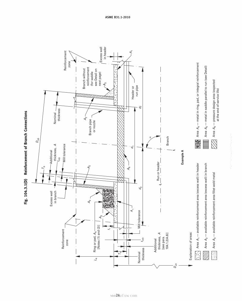
ASME B31.1-2010
Fig.
104.
3.1(
D)
Rein
forc
emen
tof
Bra
nch
Conn
ecti
ons
Mill
tole
ranc
e
Bra
nch
pipe
or
noz
zle
Nom
inal
thic
knes
s
Rei
nfor
cem
ent
zone
d 2d 2
d1
Mill
tole
ranc
e
Rin
g or
pad
, A4
[N
otes
(1) a
nd (2
)]
T h
t mh
t mb
T b
Exce
ss w
all
in b
ranc
h
Rei
nfor
cem
ent
zo
ne
Dob
A3
A3
A2
A6
c L
c L
Bra
nch
L 4
Doh
A3
Exce
ss w
all
in
hea
der
A2
A1
Expl
anat
ion
of a
reas
:
Are
aA
1 —
ava
ilabl
e re
info
rcem
ent a
rea
(exc
ess
wal
l) in
hea
der
Hea
der
or
run
pipe
A1
t r
Run
or
head
erA
dditi
onal
th
ickn
ess,
A
[see
par
a.
104.
1.2(
A.6
)]
Nom
inal
th
ickn
ess
Bra
nch
with
out
rein
forc
emen
t(f
or s
addl
ese
e D
etai
l on
next
pag
e)
Add
ition
al
thic
knes
s,A
Exam
ple
A
Are
aA
2 —
ava
ilabl
e re
info
rcem
ent a
rea
(exc
ess
wal
l) in
bra
nch
Are
aA
3 —
ava
ilabl
e re
info
rcem
ent a
rea
fille
t wel
d m
etal
Are
aA
4 —
met
al in
rin
g, p
ad, o
r in
tegr
al r
einf
orce
men
t
Are
aA
5 —
met
al in
sad
dle
para
llel t
o ru
n (s
ee D
etai
l)
Are
aA
6 —
pre
ssur
e de
sign
are
a (e
xpec
ted
at th
e en
d of
ser
vice
life
)
24
Copyright ASME International Provided by IHS under license with ASME No reproduction or networking permitted without license from IHS
--`,,```````,,```,`,`,,,,`,`,`,`-`-`,,`,,`,`,,`---
标准分享网 www.bzfxw.com 免费下载

ASME B31.1-2010
Fig.
104.
3.1(
D)
Rein
forc
emen
tof
Bra
nch
Conn
ecti
ons
(Con
t’d)
Rei
nfo
rcem
ent
ar
ea
(b)
(a)
Ex
am
ple
B
Tb
d1
d1
Tb
Th
ThRei
nfo
rcem
ent
ar
ea
t rt r
60 d
eg60
deg
Bra
nch
pip
e
or
no
zzle
Rei
nfo
rcem
ent
zo
ne A3
Exc
ess
wal
l
in h
ead
er
A2
A1
A3
Hea
der
or
ru
n p
ipe
t r
Sad
dle
, A5
[N
ote
(3)
]
90 d
eg
De
tail
for
Ex
am
ple
A
GEN
ERA
LN
OTE
S:
(a)
This
Figu
reill
ustr
ates
the
nom
encl
atur
eof
para
.10
4.3.
1(D
).(b
)Re
quir
edre
info
rcem
ent
area
pA 7
pA 6
(2−
sin
�)p
(tm
h−
A)d t
(2−
sin
�).
(c)
Ava
ilabl
ere
info
rcem
ent
area
sp
A 1+
A 2+
A 3+
A 4+
A 5(a
sap
plic
able
).(d
)A
vaila
ble
rein
forc
emen
tar
eas
≥re
quir
edre
info
rcem
ent
area
.
NO
TES
:(1
)W
hen
ari
ngor
pad
isad
ded
asre
info
rcem
ent
(Exa
mpl
eA
),th
eva
lue
ofre
info
rcem
ent
area
may
beta
ken
inth
esa
me
man
ner
inw
hich
exce
sshe
ader
met
alis
cons
ider
ed,
prov
ided
the
wel
dco
mpl
etel
yfu
ses
the
bran
chpi
pe,
head
erpi
pe,
and
ring
orpa
d.Ty
pica
lac
cept
able
met
hods
ofw
eldi
ngw
hich
mee
tth
eab
ove
requ
irem
ent
are
show
nin
Fig.
127.
4.8(
D),
sket
ches
(c)
and
(d).
(2)
Wid
thto
heig
htof
ring
san
dpa
dssh
all
bere
ason
ably
prop
orti
oned
,pr
efer
ably
ona
rati
oas
clos
eto
4:1
asth
eav
aila
ble
hori
zont
alsp
ace
wit
hin
the
limit
sof
the
rein
forc
ing
zone
alon
gth
eru
nan
dth
eou
tsid
edi
amet
erof
the
bran
chw
illpe
rmit
,bu
tin
noca
sem
ayth
era
tio
bele
ssth
an1:
1.(3
)Re
info
rcem
ent
sadd
les
are
limit
edto
use
on90
deg
bran
ches
(Exa
mpl
eA
Det
ail)
.
25
Copyright ASME International Provided by IHS under license with ASME No reproduction or networking permitted without license from IHS
--`,,```````,,```,`,`,,,,`,`,`,`-`-`,,`,,`,`,,`---
ASME B31.1-2010
(D.2.1) If the run pipe contains a longitudinalseam that is not intersected by the branch, the stressvalue of seamless pipe of comparable grade may beused to determine the value of tmh for the purpose ofreinforcement calculations only. If the branch intersectsa longitudinal weld in the run, or if the branch containsa weld, the weld joint efficiency for either or both shallenter the calculations. If the branch and run both containlongitudinal welds, care shall be taken to ensure thatthe two welds do not intersect each other.
(D.2.2) The required reinforcement area in squareinches (square millimeters) for branch connections shallbe the quantity
A7 p A6(2 − sin �) p (tmh − A)d1 (2 − sin �)
For right angle connections, the required reinforce-ment becomes
A7 p A6 p (tmh − A)d1
The required reinforcement must be within the limitsof the reinforcement zone as defined in (D.2.4) below.
(D.2.3) The reinforcement required by (D.2) shallbe that provided by any combination of areas A1, A2,A3, A4, and A5, as defined below and illustrated inFig. 104.3.1(D) where
A1 p area provided by excess pipe wall in the runp (2d2 − d1)(Th − tmh)
A2 p area, in.2 (mm2), provided by excess pipe wallin the branch for a distance L4 above the run
p 2L4 (Tb − tmb)/sin �A3 p area provided by deposited weld metal beyond
the outside diameter of the run and branch,and for fillet weld attachments of rings, pads,and saddles
A4 p area provided by a reinforcing ring, pad, orintegral reinforcement. The value of A4 maybe taken in the same manner in which excessheader metal is considered, provided the weldcompletely fuses the branch pipe, run pipe,and ring or pad, or integral reinforcement.For welding branch connections refer topara. 127.4.8.
A5 p area provided by a saddle on right angleconnections
p (O.D. of saddle − Dob)trA6 p pressure design area expected at the end of
service lifep (tmh − A)d1
Portions of the reinforcement area may be composedof materials other than those of the run pipe, but if theallowable stress of these materials is less than that forthe run pipe, the corresponding calculated reinforce-ment area provided by this material shall be reduced inthe ratio of the allowable stress being applied to thereinforcement area. No additional credit shall be takenfor materials having higher allowable stress values thanthe run pipe.
26
(D.2.4) Reinforcement Zone. The reinforcementzone is a parallelogram whose width shall extend adistance d2 on each side of the centerline of the branchpipe, and whose altitude shall start at the inside surfaceof the run pipe and extend to a distance L4 from theoutside surface of the run pipe.
(D.2.5) Reinforcement of Multiple Openings. It ispreferred that multiple branch openings be spaced sothat their reinforcement zones do not overlap. If closerspacing is necessary, the following requirement shall bemet. The two or more openings shall be reinforced inaccordance with (D.2), with a combined reinforcementthat has a strength equal to the combined strength of thereinforcement that would be required for the separateopenings. No portion of the cross section shall be consid-ered as applying to more than one opening, or be evalu-ated more than once in a combined area.
When more than two adjacent openings are to be pro-vided with a combined reinforcement, the minimumdistance between centers of any two of these openingsshould preferably be at least 11⁄2 times their averagediameter, and the area of reinforcement between themshall be at least equal to 50% of the total required forthese two openings.
(D.2.6) Rings, Pads, and Saddles. Reinforcementprovided in the form of rings, pads, or saddles shall notbe appreciably narrower at the side than at the crotch.
A vent hole shall be provided at the ring, pad, or saddleto provide venting during welding and heat treatment.Refer to para. 127.4.8(E).
Rings, pads, or saddles may be made in more thanone piece, provided the joints between pieces have fullthickness welds, and each piece is provided with avent hole.
(D.2.7) Other Designs. The adequacy of designsto which the reinforcement requirements of para. 104.3cannot be applied shall be proven by burst or prooftests on scale models or on full size structures, or bycalculations previously substantiated by successful ser-vice of similar design.
(E) Branch Connections Subject to External PressureRequiring Reinforcement. The reinforcement area insquare inches (square millimeters) required for branchconnections subject to external pressure shall be
0.5tmhd1 (2 − sin �)
where tmh is the required header wall thickness deter-mined for straight pipe under external pressure, usingprocedures outlined in UG-28, UG-29, UG-30, and UG-31of Section VIII, Division 1, of the ASME Boiler andPressure Vessel Code.
Procedures established heretofore for connections sub-ject to internal pressure shall apply for connections sub-ject to external pressure provided that Doh, Dob, and trare reduced to compensate for external corrosion, ifrequired by design conditions.
Copyright ASME International Provided by IHS under license with ASME No reproduction or networking permitted without license from IHS
--`,,```````,,```,`,`,,,,`,`,`,`-`-`,,`,,`,`,,`---
标准分享网 www.bzfxw.com 免费下载

ASME B31.1-2010
(F) Branch Connections Subject to External Forces andMoments. The requirements of the preceding para-graphs are intended to ensure safe performance of abranch connection subjected only to pressure. However,when external forces and moments are applied to abranch connection by thermal expansion and contrac-tion, by dead weight of piping, valves, and fittings, cov-ering and contents, or by earth settlement, the branchconnection shall be analyzed considering the stressintensification factors as specified in Appendix D. Useof ribs, gussets, and clamps designed in accordance withpara. 104.3.4 is permissible to stiffen the branch connec-tion, but their areas cannot be counted as contributingto the required reinforcement area of the branchconnection.
(G) Extruded Outlets Integrally Reinforced(G.1) The following definitions, modifications,
notations, and requirements are specifically applicableto extruded outlets. The designer shall make proper wallthickness allowances in order that the required mini-mum reinforcement is ensured over the design life ofthe system.
(G.2) Definition. An extruded outlet header isdefined as a header in which the extruded lip at theoutlet has an altitude above the surface of the run thatis equal to or greater than the radius of curvature of theexternal contoured portion of the outlet; i.e., ho ≥ ro. Seenomenclature and Fig. 104.3.1(G).
(G.3) These rules apply only to cases where the axisof the outlet intersects and is perpendicular to the axisof the run. These rules do not apply to any nozzle inwhich additional nonintegral material is applied in theform of rings, pads, or saddles.
(G.4) The notation used herein is illustratedin Fig. 104.3.1(G). All dimensions are in inches(millimeters).
Dob p outside diameter of branch pipeDoh p outside diameter of run
db p corroded internal diameter of branch pipedc p corroded internal diameter of extruded
outlet measured at the level of the outsidesurface of the run
dr p corroded internal diameter of runho p height of the extruded lip. This must be
equal to or greater than ro, except as shownin (G.4.2) below.
L8 p altitude of reinforcement zonep 0.7�DobTo
To p corroded finished thickness of extrudedoutlet measured at a height equal to ro
above the outside surface of the runtb − A p actual thickness of branch wall, not
including corrosion allowanceth − A p actual thickness of run wall, not including
the corrosion allowance
27
tmb − A p required thickness of branch pipeaccording to wall thickness eq. (7) or (8)in para. 104.1.2(A), but not including anythickness for corrosion
tmh − A p required thickness of the run according toeq. (7) or (8) in para. 104.1.2(A), but notincluding any allowance for corrosion
r1 p half width of reinforcement zone (equalto dc)
ro p radius of curvature of external contouredportion of outlet measured in the planecontaining the axes of the run and branch.This is subject to the following limitations:
(G.4.1) Minimum Radius. This dimensionshall not be less than 0.05Dob except thaton branch diameters larger than NPS 30,it need not exceed 1.50 in. (38 mm).
(G.4.2) Maximum Radius. For outlet pipesizes 6 in. (150 mm) nominal and larger,this dimension shall not exceed 0.10Dob +0.50 in. (0.10Dob + 12.7 mm). For outletpipe sizes less than NPS 6, this dimensionshall be not greater than 1.25 in. (32 mm).
(G.4.3) When the external contour con-tains more than one radius, the radius ofany arc sector of approximately 45 degshall meet the requirements of (G.4.1) and(G.4.2) above. When the external contourhas a continuously varying radius, theradius of curvature at every point on thecontour shall meet the requirements of(G.4.1) and (G.4.2) above.
(G.4.4) Machining other than grindingfor weld cleanup shall not be employedin order to meet the above requirements.
(G.5) Required Area. The required area is defined as
A7 p K (tmh − A) dc
where K shall be taken as follows:
For Dob/Doh greater than 0.60,
K p 1.00
For Dob/Doh greater than 0.15 and not exceeding 0.60,
K p 0.6 + 2⁄3 Dob/Doh
For Dob/Doh equal to or less than 0.15,
K p 0.70
The design must meet criteria that the reinforcementarea defined in (G.6) below is not less than therequired area.
Copyright ASME International Provided by IHS under license with ASME No reproduction or networking permitted without license from IHS
--`,,```````,,```,`,`,,,,`,`,`,`-`-`,,`,,`,`,,`---

ASME B31.1-2010
Fig. 104.3.1(G) Reinforced Extruded Outlets
Limits of reinforcement zone
30 deg max.
cof branch
Allowance
See Note (1)
(th − A)
(tb − A)
(th − A)
(tmb − A)
(tmb − A)
(tmh − A)(th − A)
Doh
ho ro
dr
To
(tb − A)
Allowance
Required areaA7 = K (tmh − A) dc
Required areaA7 = K (tmh − A) dc
Reinforcement zone
Reinforcement zone
(tmh − A)
roTo
(tmh − A)
(tmb − A)
(a)
(b)
(c) See Note (3)
(d) See Note (3)
db
Dob
ho ro
dc
dc
db
db
ho
ro
drDoh
ro
To
To dc
r1 = dc
Dob
dr
Doh
L8
A1
A4
A1
L8
r1 r1
A2
A4
A2
Allowance
r1
Dob
r1
A4
A1
A2
A4
A1
L8A2
See Note (2)
NOTES:(1) Taper bore inside diameter (if required) to match branch pipe 1:3 maximum taper.(2) Sketch to show method of establishing To when the taper encroaches on the crotch radius.(3) Sketch is drawn for condition where k p 1.00.
28
Copyright ASME International Provided by IHS under license with ASME No reproduction or networking permitted without license from IHS
--`,,```````,,```,`,`,,,,`,`,`,`-`-`,,`,,`,`,,`---
标准分享网 www.bzfxw.com 免费下载
ASME B31.1-2010
(G.6) Reinforcement Area. The reinforcement areashall be the sum of areas
A1 + A2 + A4
as defined below.(G.6.1) Area A1 is the area lying within the rein-
forcement zone resulting from any excess thicknessavailable in the run wall.
A1 p dc(tn − tmh)
(G.6.2) Area A2 is the area lying within the rein-forcement zone resulting from any excess thicknessavailable in the branch pipe wall.
A2 p 2L8(tb − tmb)
(G.6.3) Area A4 is the area lying within the rein-forcement zone resulting from excess thickness availablein the extruded outlet lip.
A4 p 2ro [To − (tb − A)]
(G.7) Reinforcement of Multiple Openings. It is pre-ferred that multiple branch openings be spaced so thattheir reinforcement zones do not overlap. If closer spac-ing is necessary, the following requirements shall bemet. The two or more openings shall be reinforced inaccordance with (G) with a combined reinforcement thathas a strength equal to the combined strength of thereinforcement that would be required for separate open-ings. No portion of the cross section shall be consideredas applying to more than one opening, or be evaluatedmore than once in a combined area.
(G.8) In addition to the above, the manufacturershall be responsible for establishing and marking on thesection containing extruded outlets, the design pressureand temperature. The manufacturer’s name or trade-marks shall be marked on the section.
104.3.3 Miters. Miter joints, and the terminologyrelated thereto, are described in Appendix D. A widelyspaced miter with
� < 9 �tn
rdeg
shall be considered to be equivalent to a girth butt-welded joint, and the rules of this paragraph do notapply. Miter joints, and fabricated pipe bends consistingof segments of straight pipe welded together, with �equal to or greater than this calculated value may beused within the limitations described below.
(A) Pressure shall be limited to 10 psi (70 kPa) underthe following conditions:
(A.1) The assembly includes a miter weld with � >22.5 deg, or contains a segment that has a dimension
B < 6tn
29
(A.2) The thickness of each segment of the miter isnot less than that determined in accordance withpara. 104.1.
(A.3) The contained fluid is nonflammable, non-toxic, and incompressible, except for gaseous vents toatmosphere.
(A.4) The number of full pressure cycles is less than7,000 during the expected lifetime of the piping system.
(A.5) Full penetration welds are used in joiningmiter segments.
(B) Pressure shall be limited to 100 psi (700 kPa) underthe conditions defined in (A.2), (A.3), (A.4), and (A.5)above, in addition to the following:
(B.1) the angle � does not exceed 22.5 deg(B.2) the assembly does not contain any segment
that has a dimension
B < 6tn
(C) Miters to be used in other services or at designpressures above 100 psi (700 kPa) shall meet the require-ments of para. 104.7.
(C.1) When justification under para. 104.7 is basedon comparable service conditions, such conditions mustbe established as comparable with respect to cyclic aswell as static loadings.
(C.2) When justification under para. 104.7 is basedon an analysis, that analysis and substantiating testsshall consider the discontinuity stresses that exist at thejuncture between segments; both for static (includingbrittle fracture) and cyclic internal pressure.
(C.3) The wall thickness, ts, of a segment of a mitershall not be less than specified in (C.3.1) or (C.3.2) below,depending on the spacing.
(C.3.1) For closely spaced miter bends (seeAppendix D for definition)
ts p tm2 − r/R
2(1 − r/R)
(C.3.2) For widely spaced miters (see AppendixD for definition)
ts p tm(1 + 0.64�r/ts tan �)
(The above equation requires an iterative or quadraticsolution for ts.)
104.3.4 Attachments. External and internal attach-ments to piping shall be designed so as not to causeflattening of the pipe, excessive localized bendingstresses, or harmful thermal gradients in the pipe wall.It is important that such attachments be designed tominimize stress concentrations in applications where thenumber of stress cycles, due either to pressure or thermaleffect, is relatively large for the expected life of theequipment.
Copyright ASME International Provided by IHS under license with ASME No reproduction or networking permitted without license from IHS
--`,,```````,,```,`,`,,,,`,`,`,`-`-`,,`,,`,`,,`---

ASME B31.1-2010
104.4 Closures
104.4.1 General. Closures for power piping sys-tems shall meet the applicable requirements of this Codeand shall comply with the requirements described in(A) or (B) below. Closures may be made
(A) by use of closure fittings, such as threaded orwelded plugs, caps, or blind flanges, manufactured inaccordance with standards listed in Table 126.1, andused within the specified pressure–temperature rat-ings, or
(B) in accordance with the rules contained in theASME Boiler and Pressure Vessel Code, Section I, PowerBoilers, PG-31, or Section VIII, Pressure Vessels, Division1, UG-34 and UW-13, calculated from
tm p t + A
wheret p pressure design thickness, calculated for the
given closure shape and direction of loadingusing appropriate equations and procedures inSection I or Section VIII, Division 1 of the ASMEBoiler and Pressure Vessel Code
The definition of A and the symbols used in determiningt shall have the definitions shown herein, instead ofthose given in the ASME Boiler and Pressure VesselCode.
Attachment of a welded flat permanent closure withonly a single fillet weld is not permitted.
104.4.2 Openings in Closures. Openings in closuresmay be made by welding, extruding, or threading.Attachment to the closure shall be in accordance withthe limitations provided for such connections in para.104.3.1 for branch connections. If the size of the openingis greater than one-half of the inside diameter of theclosure, the opening shall be designed as a reducer inaccordance with para. 104.6.
Other openings in closures shall be reinforced in accor-dance with the requirements of reinforcement for abranch connection. The total cross-sectional arearequired for reinforcement in any plane passing throughthe center of the opening and normal to the surface ofthe closure shall not be less than the quantity of d5t,where
d5 p diameter of the finished opening, in. (mm)t p as defined in (B) above
104.5 Pressure Design of Flanges and Blanks
104.5.1 Flanges — General(A) Flanges of sizes NPS 24 and smaller, that are man-
ufactured in accordance with ASME B16.1 and B16.5,shall be considered suitable for use at the primary ser-vice ratings (allowable pressure at service temperature)except the slip-on flanges to ASME B16.5 shall be limited
30
in application to no higher than Class 300 primarypressure service rating. Refer to para. 127.4.4.
For flanges larger than NPS 24, and manufactured inaccordance with the Specifications and Standards listedin Table 126.1, the designer is cautioned about thedimensionally different designs that are available, aswell as the limitations of their application.
Flanges not made in accordance with theSpecifications and Standards listed in Table 126.1 shallbe designed in accordance with Section VIII, Division 1of the ASME Boiler and Pressure Vessel Code, exceptthat the requirements for fabrication, assembly, inspec-tion, and testing, and the pressure and temperature lim-its for materials of this Code for Pressure Piping shallgovern. Certain notations used in the ASME Code,namely, P, Sa, Sb, and Sf, shall have the meaningsdescribed below instead of those given in the ASMECode. All other notations shall be as defined in theASME Code.
P p design pressure, psi (kPa) (see paras. 101.2.2and 101.2.4)
Sa p bolt design stress at atmospheric temperature,psi (kPa)
Sb p bolt design stress at design temperature, psi(kPa)
Sf p allowable stress for flange material or pipe, psi(kPa) (see para. 102.3.1 and Allowable StressTables) (stress values converted from MPa tokPa)
For certain specific applications, see the limitations ofparas. 122.1.1(F), (G), and (H).
(B) These flange design rules are not applicable toflat face designs employing full face gaskets that extendbeyond the bolts.
(C) The bolt design stress in (A) above shall be asestablished in Section VIII, Division 1 of the ASME Boilerand Pressure Vessel Code, Appendix P for ferrous mate-rials.
(D) Application of bolting materials for flanged jointsis covered in para. 108.5.
104.5.2 Blind Flanges(A) Blind flanges manufactured in accordance with
the standards listed in Table 126.1 shall be consideredsuitable for use at the pressure–temperature rating speci-fied by such standards.
(B) The required thickness of blind flanges not manu-factured in accordance with standards in Table 126.1shall be calculated from eq. (13).
tm p t + A (13)
wheret p pressure design thickness as calculated for the
given style of blind flange from the appropriateequations for bolted flat cover plates in SectionI of the ASME Boiler and Pressure Vessel Code.Certain notations used in these equations,
Copyright ASME International Provided by IHS under license with ASME No reproduction or networking permitted without license from IHS
--`,,```````,,```,`,`,,,,`,`,`,`-`-`,,`,,`,`,,`---
标准分享网 www.bzfxw.com 免费下载
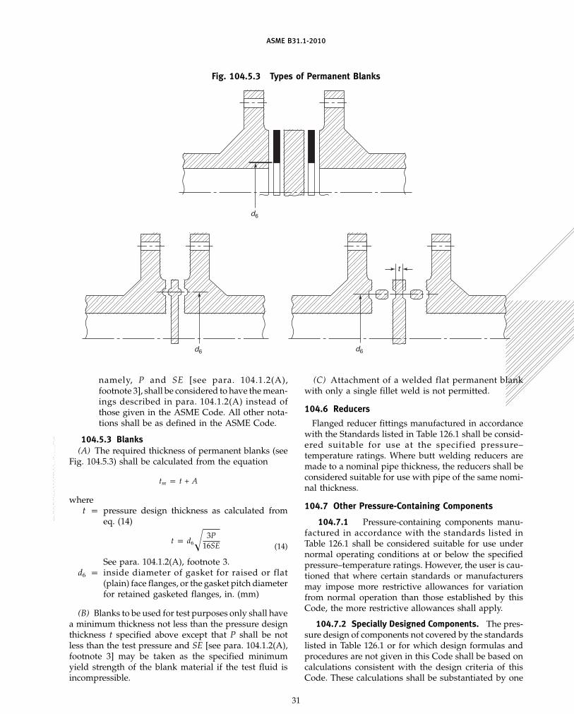
ASME B31.1-2010
Fig. 104.5.3 Types of Permanent Blanks
d6
d6 d6
t
namely, P and SE [see para. 104.1.2(A),footnote 3], shall be considered to have the mean-ings described in para. 104.1.2(A) instead ofthose given in the ASME Code. All other nota-tions shall be as defined in the ASME Code.
104.5.3 Blanks(A) The required thickness of permanent blanks (see
Fig. 104.5.3) shall be calculated from the equation
tm p t + A
wheret p pressure design thickness as calculated from
eq. (14)
t p d6� 3P16SE (14)
See para. 104.1.2(A), footnote 3.d6 p inside diameter of gasket for raised or flat
(plain) face flanges, or the gasket pitch diameterfor retained gasketed flanges, in. (mm)
(B) Blanks to be used for test purposes only shall havea minimum thickness not less than the pressure designthickness t specified above except that P shall be notless than the test pressure and SE [see para. 104.1.2(A),footnote 3] may be taken as the specified minimumyield strength of the blank material if the test fluid isincompressible.
31
(C) Attachment of a welded flat permanent blankwith only a single fillet weld is not permitted.
104.6 Reducers
Flanged reducer fittings manufactured in accordancewith the Standards listed in Table 126.1 shall be consid-ered suitable for use at the specified pressure–temperature ratings. Where butt welding reducers aremade to a nominal pipe thickness, the reducers shall beconsidered suitable for use with pipe of the same nomi-nal thickness.
104.7 Other Pressure-Containing Components
104.7.1 Pressure-containing components manu-factured in accordance with the standards listed inTable 126.1 shall be considered suitable for use undernormal operating conditions at or below the specifiedpressure–temperature ratings. However, the user is cau-tioned that where certain standards or manufacturersmay impose more restrictive allowances for variationfrom normal operation than those established by thisCode, the more restrictive allowances shall apply.
104.7.2 Specially Designed Components. The pres-sure design of components not covered by the standardslisted in Table 126.1 or for which design formulas andprocedures are not given in this Code shall be based oncalculations consistent with the design criteria of thisCode. These calculations shall be substantiated by one
Copyright ASME International Provided by IHS under license with ASME
Not for Resale, 03/08/2011 00:55:16 MSTNo reproduction or networking permitted without license from IHS
--`,,```````,,```,`,`,,,,`,`,`,`-`-`,,`,,`,`,,`---

ASME B31.1-2010
or more of the means stated in (A), (B), (C), and (D)below.
(A) extensive, successful service experience undercomparable conditions with similarly proportionedcomponents of the same or similar material
(B) experimental stress analysis, such as described inthe ASME Boiler and Pressure Vessel Code, Section VIII,Division 2, Appendix 6
(C) proof test in accordance with either ASME B16.9;MSS SP-97; or the ASME Boiler and Pressure VesselCode, Section I, A-22
(D) detailed stress analysis, such as finite elementmethod, in accordance with the ASME Boiler andPressure Vessel Code, Section VIII, Division 2, Appendix4, except that the basic material allowable stress fromthe Allowable Stress Tables of Appendix A shall be usedin place of Sm
For any of (A) through (D) above, it is permissible tointerpolate between sizes, wall thicknesses, and pressureclasses and to determine analogies among relatedmaterials.
Calculations and documentation showing compliancewith this paragraph shall be available for the owner’sapproval, and, for boiler external piping, they shall beavailable for the Authorized Inspector’s review.
104.8 Analysis of Piping Components
To validate a design under the rules in this paragraph,the complete piping system must be analyzed betweenanchors for the effects of thermal expansion, weight,other sustained loads, and other occasional loads. Eachcomponent in the system must meet the limits in thisparagraph. For pipe and fittings, the pressure term ineqs. (15) and (16) may be replaced with the alternativeterm for Slp as defined in para. 102.3.2(D). The pressureterm in eqs. (15) and (16) may not apply for bellowsand expansion joints. When evaluating stresses in thevicinity of expansion joints, consideration must be givento actual cross-sectional areas that exist at the expan-sion joint.
104.8.1 Stress Due to Sustained Loads. The effectsof pressure, weight, and other sustained mechanicalloads shall meet the requirements of eq. (15).
(U.S. Customary Units)
SL pPDo
4tn+
0.75iMA
Z≤ 1.0 Sh (15)
(SI Units)
SL pPDo
(1 000)4tn+
0.75iMA
Z≤ 1.0 Sh
32
wherei p stress intensification factor (see Appendix D).
The product 0.75i shall never be taken as lessthan 1.0.
MA p resultant moment loading on cross section dueto weight and other sustained loads, in-lb(mm-N) (see para. 104.8.4)
Sh p basic material allowable stress at maximum(hot) temperature [see para. 102.3.2(D)]
SL p sum of the longitudinal stresses due to pres-sure, weight, and other sustained loads
Z p section modulus, in.3 (mm3) (see para. 104.8.4)
104.8.2 Stress Due to Occasional Loads. The effectsof pressure, weight, other sustained loads, and occa-sional loads including earthquake shall meet the require-ments of eq. (16).
(U.S. Customary Units)
PDo
4tn+
0.75iMA
Z+
0.75iMB
Z≤ kSh (16)
(SI Units)
PDo
(1 000)4tn+
0.75iMA
Z+
0.75iMB
Z≤ kSh
Terms same as para. 104.8.1, exceptk p 1.15 for occasional loads acting for no more
than 8 hr at any one time and no more than800 hr/yr [see para. 102.3.3(A)]
p 1.2 for occasional loads acting for no more than1 hr at any one time and no more than 80 hr/yr[see para. 102.3.3(A)]
MB p resultant moment loading on the cross sectiondue to occasional loads, such as thrusts fromrelief/safety valve loads, from pressure andflow transients, and earthquake, in.-lb (mm-N)[see paras. 102.3.3(A) and 104.8.4]
104.8.3 Stress Due to Displacement Load Ranges.The effects of thermal expansion and other cyclic loadsshall meet the requirements of eq. (17).
(U.S. Customary Units)
SE piMC
Z≤ SA (17)
(SI Units)
SE p1 000(iMC)
Z≤ SA
Terms same as para. 104.8.1, exceptMC p resultant moment loading range on the cross
section due to the reference displacement loadrange. For flexibility analyses, the resultantmoment due to the ambient to normal
Copyright ASME International Provided by IHS under license with ASME No reproduction or networking permitted without license from IHS
--`,,```````,,```,`,`,,,,`,`,`,`-`-`,,`,,`,`,,`---
标准分享网 www.bzfxw.com 免费下载
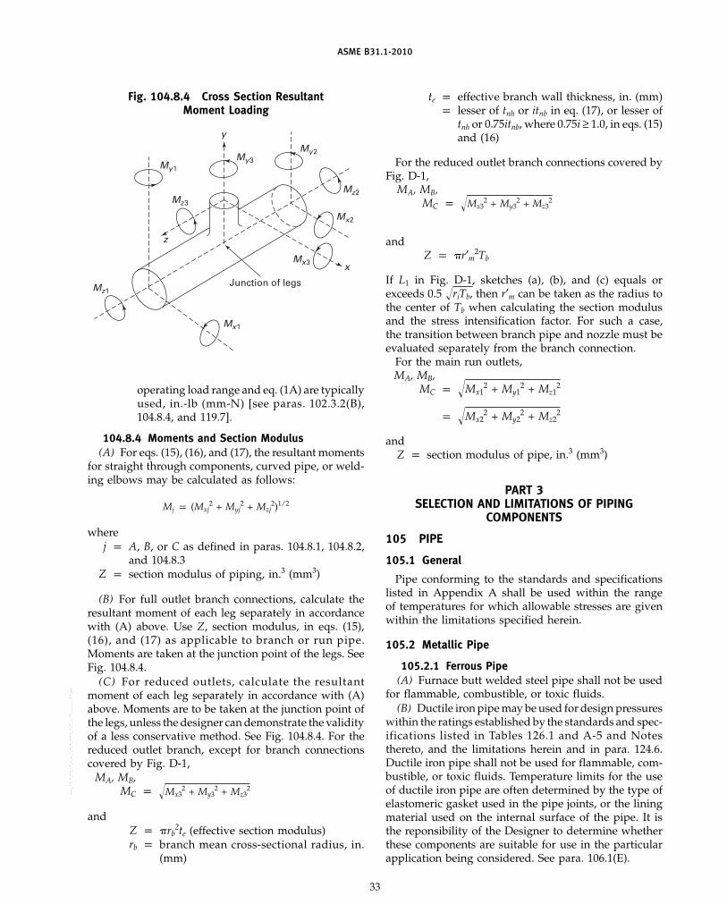
ASME B31.1-2010
Fig. 104.8.4 Cross Section ResultantMoment Loading
My1
My3
My2
Mz2
Mx2
Mx3
Mx1
Mz3
Mz1
y
x
z
Junction of legs
operating load range and eq. (1A) are typicallyused, in.-lb (mm-N) [see paras. 102.3.2(B),104.8.4, and 119.7].
104.8.4 Moments and Section Modulus(A) For eqs. (15), (16), and (17), the resultant moments
for straight through components, curved pipe, or weld-ing elbows may be calculated as follows:
Mj p (Mxj2 + Myj
2 + Mzj2)1/2
wherej p A, B, or C as defined in paras. 104.8.1, 104.8.2,
and 104.8.3Z p section modulus of piping, in.3 (mm3)
(B) For full outlet branch connections, calculate theresultant moment of each leg separately in accordancewith (A) above. Use Z, section modulus, in eqs. (15),(16), and (17) as applicable to branch or run pipe.Moments are taken at the junction point of the legs. SeeFig. 104.8.4.
(C) For reduced outlets, calculate the resultantmoment of each leg separately in accordance with (A)above. Moments are to be taken at the junction point ofthe legs, unless the designer can demonstrate the validityof a less conservative method. See Fig. 104.8.4. For thereduced outlet branch, except for branch connectionscovered by Fig. D-1,
MA, MB,MC p �Mx3
2 + My32 + Mz3
2
andZ p �rb
2te (effective section modulus)rb p branch mean cross-sectional radius, in.
(mm)
33
te p effective branch wall thickness, in. (mm)p lesser of tnh or itnb in eq. (17), or lesser of
tnh or 0.75itnb, where 0.75i ≥ 1.0, in eqs. (15)and (16)
For the reduced outlet branch connections covered byFig. D-1,
MA, MB,MC p �Mx3
2 + My32 + Mz3
2
andZ p �r′m2Tb
If L1 in Fig. D-1, sketches (a), (b), and (c) equals orexceeds 0.5 �riTb, then r′m can be taken as the radius tothe center of Tb when calculating the section modulusand the stress intensification factor. For such a case,the transition between branch pipe and nozzle must beevaluated separately from the branch connection.
For the main run outlets,MA, MB,
MC p �Mx12 + My1
2 + Mz12
p �Mx22 + My2
2 + Mz22
andZ p section modulus of pipe, in.3 (mm3)
PART 3SELECTION AND LIMITATIONS OF PIPING
COMPONENTS
105 PIPE
105.1 General
Pipe conforming to the standards and specificationslisted in Appendix A shall be used within the rangeof temperatures for which allowable stresses are givenwithin the limitations specified herein.
105.2 Metallic Pipe
105.2.1 Ferrous Pipe(A) Furnace butt welded steel pipe shall not be used
for flammable, combustible, or toxic fluids.(B) Ductile iron pipe may be used for design pressures
within the ratings established by the standards and spec-ifications listed in Tables 126.1 and A-5 and Notesthereto, and the limitations herein and in para. 124.6.Ductile iron pipe shall not be used for flammable, com-bustible, or toxic fluids. Temperature limits for the useof ductile iron pipe are often determined by the type ofelastomeric gasket used in the pipe joints, or the liningmaterial used on the internal surface of the pipe. It isthe reponsibility of the Designer to determine whetherthese components are suitable for use in the particularapplication being considered. See para. 106.1(E).
Copyright ASME International Provided by IHS under license with ASME No reproduction or networking permitted without license from IHS
--`,,```````,,```,`,`,,,,`,`,`,`-`-`,,`,,`,`,,`---
ASME B31.1-2010
105.2.2 Nonferrous Pipe(A) Copper and brass pipe for water and steam ser-
vice may be used for design pressures up to 250 psi(1 750 kPa) and for design temperatures to 406°F (208°C).
(B) Copper and brass pipe for air may be used inaccordance with the allowable stresses given in theAllowable Stress Tables.
(C) Copper tubing may be used for dead-endinstrument service with the limitations stated inpara. 122.3.2(D).
(D) Copper, copper alloy, or aluminum alloy pipe ortube may be used under the conditions stated inpara. 124.7. Copper, copper alloy, or aluminum pipe ortube shall not be used for flammable, combustible, ortoxic fluids except as permitted in paras. 122.7 and 122.8.
105.3 Nonmetallic Pipe(A) Plastic pipe may be used for water and nonflam-
mable liquids where experience or tests have demon-strated that the plastic pipe is suitable for the serviceconditions, and the pressure and temperature conditionsare within the manufacturer’s recommendations. Untilsuch time as mandatory rules are established for thesematerials, pressure shall be limited to 150 psi (1 000 kPa)and temperature to 140°F (60°C) for water service. Pres-sure and temperature limits for other services shall bebased on the hazards involved, but in no applicationshall they exceed 150 psi (1 000 kPa) and 140°F (60°C).For nonmandatory rules for nonmetallic piping, seeAppendix III of this Code.
(B) Reinforced thermosetting resin pipe may be used,in addition to the services listed in para. 105.3(A), inburied flammable and combustible liquid service subjectto the limitations described in para. 122.7.3(F).
(C) Reinforced concrete pipe may be used in accor-dance with the specifications listed in Table 126.1 forwater service up to 150°F (65°C).
(D) A flexible nonmetallic pipe or tube assembly maybe used in applications where
(D.1) satisfactory service experience exists(D.2) the pressure and temperature conditions are
within the manufacturer’s recommendations(D.3) the conditions described in paras. 104.7, 124.7,
and 124.9 are met(E) Polyethylene pipe may be used, in addition to the
services listed in para. 105.3(A), in buried flammableand combustible liquid and gas service subject to thelimitations described in paras. 122.7.2(D) and122.8.1(B.4).
(F) Metallic piping lined with nonmetals may be usedfor fluids that would corrode or be contaminated byunprotected metal. See para. 122.9 and Appendix III.
106 FITTINGS, BENDS, AND INTERSECTIONS106.1 Fittings
(A) Threaded, flanged, grooved and shoulderedsocket-welding, buttwelding, compression, push-on,
34
mechanical gland, and solder-joint fittings made inaccordance with the applicable standards in Table 126.1may be used in power piping systems within the mate-rial, size, pressure, and temperature limitations of thosestandards, and within any further limitations specifiedin this Code. Material for fittings in flammable, combus-tible, or toxic fluid systems shall in addition conformto the requirements of paras. 122.7 and 122.8.
(B) Fittings not covered by the Standards listed inTable 126.1 may be used if they conform to para. 104.7.
(C) Cast buttwelding steel fittings not covered by thedimensional standards listed in Table 126.1 may be usedup to the manufacturer’s pressure and temperature rat-ings, provided they are radiographed in accordance withthe method of ASTM E 94 and meet the acceptancerequirements of ASTM E 446, E 186, and E 280 as applica-ble for the thickness being radiographed.
(D) Fabricated ends for grooved and shouldered typejoints are acceptable, provided they are attached by fullpenetration welds, double fillet welds, or by threading.Fabricated ends attached by single fillet welds are notacceptable.
(E) Elastomeric gasket bell end fittings complyingwith applicable standards listed in Table 126.1 may beused for water service. Temperature limits for gray andductile iron fittings using ANSI/AWWA C111/A21.11joints are 65°C (150°F) for push-on joints and 49°C(120°F) for mechanical joints, based on standard waterservice gasket and lining materials. Fittings of this typeusing alternative materials, as allowed by AWWA C111,may be used for nonflammable, nontoxic service to100°C (212°F), where suitability for the fluid andoperating conditions has been established by test orexperience. Temperature limits for bell and spigot fit-tings in nonmetallic pipe shall be per para. 105.3.
106.2 Bends and Intersections
Bends and extruded branch connections may be usedwhen designed in accordance with the provisions ofparas. 104.2 and 104.3, respectively. Miters may be usedwithin the limitations of para. 104.3.3.
106.3 Pipe Couplings and Unions
(A) Cast iron and malleable iron pipe couplings shallbe limited in application as referenced in paras. 124.4and 124.5, respectively.
(B) Straight thread couplings shall not be used.(C) Class 3000 steel pipe unions constructed in accor-
dance with the MSS standard SP-83 may be used, pro-vided the system design conditions are within thestandard’s listed pressure–temperature ratings.
106.4 Flexible Metal Hose Assembly
(A) Flexible metal hose assemblies may be used toprovide flexibility in a piping system, to isolate or controlvibration, or to compensate for misalignment. The
Copyright ASME International Provided by IHS under license with ASME No reproduction or networking permitted without license from IHS
--`,,```````,,```,`,`,,,,`,`,`,`-`-`,,`,,`,`,,`---
标准分享网 www.bzfxw.com 免费下载

(10)
(10)
ASME B31.1-2010
design conditions shall be in accordance with para. 101and within the limitations of the assembly as recom-mended by the manufacturer. The basis for their applica-tion shall include the following service conditions:thermal cycling, bend radius, cycle life, and the possibil-ity of corrosion and erosion. Installation shall be limitedto a single-plane bend, free from any torsion effectsduring service conditions and nonoperating periods.Type of end-connector components shall be consistentwith the requirements of this Code.
(B) A flexible metal hose assembly, consisting of onecontinuous length of seamless or butt welded tube withhelical or annular corrugations, is not limited as to appli-cation in piping systems that are within the scope ofthis Code, provided that the conditions described in(A) above are met. For application subject to internalpressure the flexible element shall be contained withinone or more separate layers of braided metal perma-nently attached at both coupling ends by welding orbrazing. For application in toxic fluid systems, it is rec-ommended that the designer also review the standardspublished by the relevant fluid industry for any addi-tional safety and materials requirements that may benecessary.
(C) A flexible metal hose assembly consisting ofwound interlocking metal strips may be applied to atmo-spheric vent systems only and shall not be used in sys-tems that convey high temperature, flammable, toxic,or searching-type fluids. Where applicable, as deter-mined by the designer and within the limitationsdescribed in para. 122.6 and those imposed by the manu-facturer, this type of hose assembly may be used atpressure relieving devices.
107 VALVES
107.1 General
(A) Valves complying with the standards and specifi-cations listed in Table 126.1 shall be used within thespecified pressure–temperature ratings. Unless other-wise required in the individual standards and specifica-tions listed in Table 126.1, such steel valves shall bepressure tested in accordance with MSS SP-61.
(B) Valves not complying with (A) above shall be ofa design, or equal to the design, that the manufacturerrecommends for the service as stipulated in para. 102.2.2.Such valves shall be pressure tested in accordance withMSS SP-61.
(C) Some valves are capable of sealing simultaneouslyagainst a pressure differential between an internal cavityof the valve and the adjacent pipe in both directions.Where liquid is entrapped in such a valve and is subse-quently heated, a dangerous rise in pressure can result.Where this condition is possible, the Owner shall pro-vide means in design, installation, and/or operation toensure that the pressure in the valve shall not exceed
35
the rated pressure for the attained temperature. A reliefdevice used solely for the overpressure protection fromsuch entrapped fluid and conforming to (A) or (B) aboveneed not comply with the requirements of para. 107.8.Any penetration of the pressure retaining wall of thevalve shall meet the requirements of this Code.
(D) Only valves designed such that the valve stem isretained from blowout by an assembly that functionsindependently of the stem seal retainer shall be used.
(E) Materials used for pressure retention for valvesin flammable, combustible, or toxic fluid systems shallin addition conform to the requirements of paras. 122.7and 122.8.
(F) When selecting diaphragm valves in accordancewith MSS standard SP-88, the designer shall specifythe proper category pressure–temperature rating for thesystem design conditions, and should consider theexpected in-service and shelf lives of the diaphragmmaterial.
(G) Pressure regulating valves may have pressure rat-ings in accordance with ANSI/FCI Standard 79-1. Regu-lators having two static pressure ratings, i.e., inlet vs.outlet, shall be installed with adequate overpressure pro-tection devices to prevent excessive downstream pres-sure resulting from any system failure. Refer toparas. 122.5 and 122.14.
107.2 Marking
Each valve shall bear the manufacturer ’s name ortrademark and reference symbol to indicate the serviceconditions for which the manufacturer guarantees thevalve. The marking shall be in accordance withASME B16.5 and B16.34. MSS SP-25 may also be usedfor guidance.
107.3 Ends
Valves may be used with flanged, threaded, butt weld-ing, socket welding, or other ends in accordance withapplicable standards as specified in para. 107.1(A).
107.4 Stem Threads
Where threaded stem valves are used, stem threadsmay be internal or external with reference to the valvebonnet. Outside screw and yoke design shall be usedfor valves NPS 3 and larger for pressures above 600 psi(4 135 kPa). This requirement is not applicable to quar-ter-turn valves that comply with all other provisions ofthis Code.
107.5 Bonnet Joints
Bonnet joints may be of flanged, welded, pressure seal,union type, or other design, except that screwed bonnetconnections in which the seal depends on a steam tightthreaded joint shall not be permitted as source valvesin steam service at pressures above 250 psi (1 750 kPa).
(10)
Copyright ASME International Provided by IHS under license with ASME No reproduction or networking permitted without license from IHS
--`,,```````,,```,`,`,,,,`,`,`,`-`-`,,`,,`,`,,`---
ASME B31.1-2010
107.6 Bypasses
Sizes of bypasses shall be in accordance withMSS SP-45 as a minimum standard. Pipe for bypassesshall be at least schedule 80 seamless, and of a materialof the same nominal chemical composition and physicalproperties as that used for the main line. Bypasses maybe integral or attached.
107.8 Safety, Safety Relief, and Relief Valves
107.8.1 General. Safety, safety relief, and reliefvalves shall conform to the requirements specified inthis Code for flanges, valves, and fittings for the pres-sures and temperatures to which they may be subjected.
107.8.2 Safety, Safety Relief, and Relief Valves onBoiler External Piping. Safety, safety relief, and reliefvalves on boiler external piping shall be in accordancewith para. 122.1.7(D.1) of this Code.
107.8.3 Safety, Safety Relief, and Relief Valves onNonboiler External Piping. Safety, safety relief, and reliefvalves on nonboiler external piping (except for reheatsafety valves) shall be in accordance with the require-ments of the ASME Boiler and Pressure Vessel Code,Section VIII, Division 1, UG-126 through UG-133. Forvalves with set pressures 15 psig [100 kPa (gage)] andlower, an ASME Code Stamp and capacity certificationare not required. Reheat safety valves shall be in accor-dance with the requirements of the ASME Boiler andPressure Vessel Code, Section I, PG-67 through PG-73.
107.8.4 Nonmandatory Appendix. For nonmanda-tory rules for the design of safety valve installations,see Appendix II of this Code.
108 PIPE FLANGES, BLANKS, FLANGE FACINGS,GASKETS, AND BOLTING
108.1 Flanges
Flanges shall conform to the design requirements ofpara. 104.5.1 or to the standards listed in Table 126.1.They may be integral or shall be attached to pipe bythreading, welding, brazing, or other means within theapplicable standards specified in Table 126.1.
108.2 Blanks
Blanks shall conform to the design requirements ofpara. 104.5.3.
108.3 Flange Facings
Flange facings shall be in accordance with the applica-ble standards listed in Tables 112 and 126.1. When bolt-ing Class 150 standard steel flanges to flat face cast ironflanges, the steel flange shall be furnished with a flatface. Steel flanges of Class 300 raised face standard maybe bolted to Class 250 raised face cast iron.
36
108.4 Gaskets
Gaskets shall be made of materials that are not injuri-ously affected by the fluid or by temperature. They shallbe in accordance with Table 112.
108.5 U.S. Customary Bolting
108.5.1 General(A) Bolts, bolt studs, nuts, and washers shall comply
with applicable standards and specifications listed inTables 112 and 126.1. Bolts and bolt studs shall extendcompletely through the nuts.
(B) Washers, when used under nuts, shall be of forgedor rolled material with steel washers being used understeel nuts and bronze washers under bronze nuts.
(C) Nuts shall be provided in accordance with therequirements of the specification for the bolts and boltstuds.
(D) Alloy steel bolt studs shall be either threaded fulllength or provided with reduced shanks of a diameternot less than that at the root of the threads. They shallhave ASME heavy hexagonal nuts. Headed alloy boltsshall not be used with other than steel or stainless steelflanges.
(E) All alloy steel bolt studs and carbon steel bolts orbolt studs and accompanying nuts shall be threaded inaccordance with ASME B1.1 Class 2A for externalthreads and Class 2B for internal threads. Threads shallbe the coarse-thread series except that alloy steel bolting11⁄8 in. and larger in diameter shall be the 8-pitch-threadseries.
(F) Carbon steel headed bolts shall have square, hex,or heavy hex heads (ASME B18.2.1) and shall be usedwith hex or heavy hex nuts (ASME B18.2.2). For boltsizes smaller than 3⁄4 in., square or heavy hex heads andheavy hex nuts are recommended. For bolt sizes largerthan 11⁄2 in., bolt studs with a hex or heavy hex nut oneach end are recommended. For cast iron or bronzeflanges using 3⁄4 in. and larger carbon steel headed bolts,square nuts may be used.
108.5.2 For the various combinations of flangematerials, the selection of bolting materials and relatedrules concerning flange faces and gaskets shall be inaccordance with para. 108 and Table 112.
108.5.3 Bolting requirements for components notcovered by para. 108.5.2 shall be in accordance withpara. 102.2.2.
108.6 Metric Bolting
108.6.1 General. The use of metric bolts, bolt studs,nuts, and washers shall conform to the general require-ments of para. 108.5, but the following are allowed:
(A) Threads shall be in accordance withASME B1.13M, M profile, with tolerance Class 6g forexternal threads and Class 6H for internal threads.
Copyright ASME International Provided by IHS under license with ASME No reproduction or networking permitted without license from IHS
--`,,```````,,```,`,`,,,,`,`,`,`-`-`,,`,,`,`,,`--- 标准分享网 www.bzfxw.com 免费下载

ASME B31.1-2010
(B) Threads shall be the coarse-thread series for sizeM68 and smaller, and 6 mm fine-pitch for M70 and largersizes, except that alloy steel bolting M30 and larger shallbe the 3 mm fine-pitch.
(C) Nuts shall be heavy hex in accordance withASME B18.2.4.6M. Headed bolts shall be either hex orheavy hex in accordance with ASME B18.2.3.5M andB18.2.3.6M, respectively. Heavy hex heads are recom-mended for headed bolt sizes M18 and smaller.
(D) Bolt studs are recommended in lieu of headedbolts for sizes M39 and larger.
108.6.2 Responsibilities When Specifying orAllowing Metric Bolting
(A) The piping designer is responsible for specifyingthe metric bolt size to be used with each class and sizeof flange.
(B) The designer shall ensure that the selected metricsize will fit within the flange bolt holes, and that ade-quate space exists for bolt heads, nuts, and the assem-bly tool.
(C) In those instances where the selected metric boltsize is smaller in root thread area than the correspondingU.S. Customary size, the designer shall ensure that theselected size is capable of the required assembly torqueand of producing the required gasket loading to ade-quately seal at design pressure. Further, the designershall ensure sufficient contact area exists between theflange metal and both the nut and bolt head to withstandthe required bolt loading. If not, larger bolting or ahigher flange class shall be selected.
PART 4SELECTION AND LIMITATIONS OF PIPING JOINTS
110 PIPING JOINTS
The type of piping joint used shall be suitable for thedesign conditions and shall be selected with consider-ation of joint tightness, mechanical strength, and thenature of the fluid handled.
111 WELDED JOINTS
111.1 General
Welded joints may be used in any materials allowedby this Code for which it is possible to qualify WPSs,welders, and welding operators in conformance withthe rules established in Chapter V.
All welds shall be made in accordance with the appli-cable requirements of Chapter V.
111.2 Butt Welds
111.2.1 Design of Butt Welds. The design of buttwelds shall include the evaluation of any expected jointmisalignment [para. 127.3(C)] that may result from speci-fication of joint geometries at variance with the recom-mendations of this Code.
37
111.2.2 Backing Rings for Butt Welds. If backingrings are used in services where their presence will resultin severe corrosion or erosion, the backing ring shall beremoved and the internal surface ground smooth. Insuch services, where it is impractical to remove the back-ing ring, consideration shall be given to welding thejoint without a backing ring, or with a consumable typeinsert ring.
111.3 Socket Welds
111.3.1 Restrictions on size of socket welded com-ponents are given in paras. 104.3.1(B.4), 122.1.1(H), and122.8.2(C). Special consideration should be given to fur-ther restricting the use of socket welded piping jointswhere temperature or pressure cycling or severe vibra-tion is expected to occur or where the service may accel-erate crevice corrosion.
111.3.2 Dimensions for sockets of socket weldingcomponents shall conform to ASME B16.5 for flangesand ASME B16.11 for fittings. Assembly of socketwelded joints shall be made in accordance withpara. 127.3(E).
111.3.3 A branch connection socket weldeddirectly into the wall of the run pipe shall be in accor-dance with requirements of para. 104.3.1(B.4).
111.3.4 Drains and bypasses may be attached toa fitting or valve by socket welding, provided the socketdepth, bore diameter, and shoulder thickness conformto the requirements of ASME B16.11.
111.4 Fillet Welds
Fillet welds shall have dimensions not less than theminimum dimensions shown in Figs. 127.4.4(B),127.4.4(C), and 127.4.8(D).
111.5 Seal Welds
Seal welding of connections, including threaded joints,may be used to avoid joint leakage, but the welding shallnot be considered as contributing any strength to thejoint. Also see para. 127.4.5. Seal welded threaded jointsare subject to the limitations of para. 114.
112 FLANGED JOINTS
Flanged joints shall conform to paras. 108 and 110 andTable 112.
113 EXPANDED OR ROLLED JOINTS
Expanded or rolled joints may be used where experi-ence or test has demonstrated that the joint is suitablefor the design conditions and where adequate provisionsare made to prevent separation of the joint.
Copyright ASME International Provided by IHS under license with ASME No reproduction or networking permitted without license from IHS
--`,,```````,,```,`,`,,,,`,`,`,`-`-`,,`,,`,`,,`---

ASME B31.1-2010
Tabl
e11
2Pi
ping
Flan
geB
olti
ng,
Faci
ng,
and
Gas
ket
Requ
irem
ents
(Ref
erto
Para
s.10
8,11
0,an
d11
2)
Flan
geA
Mat
ing
Wit
hFl
ange
B
Item
Flan
geA
Flan
geB
Bol
ting
Flan
geFa
cing
sG
aske
ts
(a)
Clas
s25
cast
iron
Clas
s25
cast
iron
(a)(
1)“L
owst
reng
th”
(a)(
1)Fl
at(a
)(1)
Flat
ring
nonm
etal
licto
[Not
es(1
),(2
),an
d(3
)]A
SME
B16
.21,
Tabl
e1
(a)(
2)“H
ighe
rst
reng
th”
or(a
)(2)
Flat
(a)(
2)Fu
llfa
ceno
nmet
allic
to“l
owst
reng
th”
ASM
EB
16.2
1,Ta
ble
1[N
otes
(1)
thro
ugh
(5)]
(b)
Clas
s12
5ca
stir
onCl
ass
125
cast
iron
,“L
owst
reng
th”
Flat
Flat
ring
;no
nmet
allic
toCl
ass
150
stee
lan
dst
ainl
ess
[Not
es(1
),(2
),an
d(3
)]A
SME
B16
.21,
Tabl
e2
stee
l(e
xclu
ding
MSS
SP-
51),
orCl
ass
150
duct
ileir
on
(c)
Clas
s12
5ca
stir
on,
Clas
s12
5ca
stir
on,
“Hig
her
stre
ngth
”or
“low
Flat
Full
face
nonm
etal
licto
Clas
s15
0br
onze
,Cl
ass
150
bron
ze,
stre
ngth
”[N
otes
(1)
ASM
EB
16.2
1,Ta
ble
2M
SSS
P-51
stai
nles
sst
eel,
orCl
ass
150
stee
lan
dst
ainl
ess
thro
ugh
(7)]
[Not
es(8
),(9
)]N
onm
etal
licst
eel
(inc
ludi
ngM
SSS
P-51
),Cl
ass
150
duct
ileir
on,
orN
onm
etal
lic
(d)
Clas
s15
0st
eel
and
stai
nles
sCl
ass
150
stee
lan
dst
ainl
ess
(d)(
1)“L
owst
reng
th”
(d)(
1)Ra
ised
orfla
ton
one
(d)(
1)Fl
atri
ngno
nmet
allic
tost
eel
(exc
ludi
ngM
SSS
P-51
),st
eel
(exc
ludi
ngM
SSS
P-51
),[N
otes
(1),
(2),
and
(3)]
orbo
thfla
nges
ASM
EB
16.5
,A
nnex
C,or
orG
roup
Ia,
Tabl
eC1
Clas
s15
0du
ctile
iron
Clas
s15
0du
ctile
iron
[Not
e(1
0)]
(d)(
2)“H
ighe
rst
reng
th”
(d)(
2)Ra
ised
orfla
ton
one
(d)(
2)Ri
ngst
yle
toA
SME
[Not
es(3
),(4
),an
d(5
)]or
both
flang
esB
16.5
,A
nnex
C,G
roup
sIa
and
Ib,
Tabl
eC1
[Not
es(1
0)an
d(1
1)]
(d)(
3)“H
ighe
rst
reng
th”
or(d
)(3)
Flat
(d)(
3)Fu
llfa
ce“l
owst
reng
th”
nonm
etal
licto
[Not
es(1
)th
roug
h(5
)]A
SME
B16
.5,
Ann
exC,
Gro
upIa
mat
eria
l
(e)
Clas
s15
0st
eel
and
stai
nles
sCl
ass
150
stee
lan
dst
ainl
ess
“Hig
her
stre
ngth
”Ri
ngjo
int
Ring
join
tto
ASM
EB
16.2
0st
eel
(exc
ludi
ngM
SSS
P-51
)st
eel
(exc
ludi
ngM
SSS
P-51
)[N
otes
(3),
(4),
and
(5)]
38
Copyright ASME International Provided by IHS under license with ASME No reproduction or networking permitted without license from IHS
--`,,```````,,```,`,`,,,,`,`,`,`-`-`,,`,,`,`,,`---
标准分享网 www.bzfxw.com 免费下载

ASME B31.1-2010
Tabl
e11
2Pi
ping
Flan
geB
olti
ng,
Faci
ng,
and
Gas
ket
Requ
irem
ents
(Con
t‘d)
(Ref
erto
Para
s.10
8,11
0,an
d11
2)
Flan
geA
Mat
ing
Wit
hFl
ange
B
Item
Flan
geA
Flan
geB
Bol
ting
Flan
geFa
cing
sG
aske
ts
(f)
Clas
s25
0ca
stir
onCl
ass
250
cast
iron
,(f
)(1)
“Low
stre
ngth
”(f
)(1)
Rais
edor
flat
onon
e(f
)(1)
Flat
ring
nonm
etal
licto
Clas
s30
0st
eel
and
stai
nles
s[N
otes
(1),
(2),
and
(3)]
orbo
thfla
nges
ASM
EB
16.2
1,Ta
ble
3st
eel,
or(f
)(2)
“Hig
her
stre
ngth
”or
(f)(
2)Fl
at(f
)(2)
Full
face
nonm
etal
licto
Clas
s30
0du
ctile
iron
“low
stre
ngth
”A
SME
B16
.21
Tabl
e6
[Not
es(1
)th
roug
h(5
)](C
lass
300)
(g)
Clas
s30
0br
onze
Clas
s25
0ca
stir
on,
“Hig
her
stre
ngth
”or
“low
Flat
Full
face
nonm
etal
licto
Clas
s30
0br
onze
,st
reng
th”
[Not
es(1
)A
SME
B16
.21,
Tabl
e11
Clas
s30
0st
eel
and
stai
nles
sth
roug
h(7
)][N
ote
(8)]
stee
l,or
Clas
s30
0du
ctile
iron
(h)
Clas
s30
0du
ctile
iron
Clas
s30
0st
eel
and
stai
nles
s(h
)(1)
“Low
stre
ngth
”(h
)(1)
Rais
edor
flat
onon
eor
(h)(
1)Fl
atri
ngno
nmet
allic
tost
eel,
or[N
otes
(1),
(2),
and
(3)]
both
flang
esA
SME
B16
.5,
Ann
exC,
Clas
s30
0du
ctile
iron
Gro
upIa
,Ta
ble
C1[N
ote
(10)
]
(h)(
2)“H
ighe
rst
reng
th”
(h)(
2)Ra
ised
orfla
ton
one
or(h
)(2)
Ring
styl
eto
[Not
es(3
),(4
)an
d(5
)]bo
thfla
nges
ASM
EB
16.5
,A
nnex
C[N
otes
(10)
and
(11)
]
(h)(
3)“H
ighe
rst
reng
th”
or(h
)(3)
Flat
(h)(
3)Fu
llfa
ce“l
owst
reng
th”
nonm
etal
licto
[Not
es(1
)th
roug
h(5
)]A
SME
B16
.5,
Ann
exC,
Gro
upIa
mat
eria
l[N
ote
(10)
]
39
Copyright ASME International Provided by IHS under license with ASME No reproduction or networking permitted without license from IHS
--`,,```````,,```,`,`,,,,`,`,`,`-`-`,,`,,`,`,,`---

ASME B31.1-2010
Tabl
e11
2Pi
ping
Flan
geB
olti
ng,
Faci
ng,
and
Gas
ket
Requ
irem
ents
(Con
t’d)
(Ref
erto
Para
s.10
8,11
0,an
d11
2)
Flan
geA
Mat
ing
Wit
hFl
ange
B
Item
Flan
geA
Flan
geB
Bol
ting
Flan
geFa
cing
sG
aske
ts
(i)
Clas
s30
0an
dhi
gher
clas
ses,
Clas
s30
0an
dhi
gher
clas
ses,
(i)(
1)“L
owst
reng
th”
(i)(
1)Ra
ised
orfla
ton
one
or(i
)(1)
Flat
ring
nonm
etal
licto
stee
lan
dst
ainl
ess
stee
lst
eel
and
stai
nles
sst
eel
[Not
es(1
),(2
),an
d(3
)]bo
thfla
nges
;la
rge
orA
SME
B16
.5,
para
.6.
11sm
all
mal
ean
dfe
mal
e;an
dA
nnex
C,la
rge
orsm
all
tong
ueG
roup
Iam
ater
ial
and
groo
ve[N
ote
(10)
]
(i)(
2)“H
ighe
rst
reng
th”
(i)(
2)Ra
ised
orfla
ton
one
or(i
)(2)
Ring
styl
eto
[Not
es(3
),(4
),an
d(5
)]bo
thfla
nges
;la
rge
orA
SME
B16
.5,
para
.6.
11sm
all
mal
ean
dfe
mal
e;an
dA
nnex
Cla
rge
orsm
all
tong
ue[N
otes
(10)
and
(11)
]an
dgr
oove
(i)(
3)“H
ighe
rst
reng
th”
(i)(
3)Ri
ngjo
int
(i)(
3)Ri
ngjo
int
to[N
otes
(3),
(4),
and
(5)]
ASM
EB
16.2
0
(j)
Clas
s80
0ca
stir
onCl
ass
800
cast
iron
“Low
stre
ngth
”Ra
ised
orla
rge
mal
ean
dFl
atri
ngno
nmet
allic
to[N
otes
(1),
(2),
and
(3)]
fem
ale
ASM
EB
16.2
1,Ta
ble
4
GEN
ERA
LN
OTE
S:
(a)
Bol
ting
(inc
ludi
ngnu
ts),
flang
efa
cing
,an
dga
sket
sele
ctio
n(m
ater
ials
,di
men
sion
s,bo
ltst
ress
,ga
sket
fact
or,
seat
ing
stre
ss,
etc.
)sh
all
besu
itabl
efo
rth
efla
nges
,se
rvic
eco
ndit
ions
,an
dhy
dros
tati
cte
sts.
Ther
esh
all
beno
over
stre
ssin
gof
the
gask
etor
flang
esfr
omth
eex
pect
edbo
ltlo
adin
gor
exte
rnal
bend
ing
load
s.(b
)U
nles
sot
herw
ise
stat
ed,
the
flang
efa
cing
desc
ribe
dap
plie
sto
both
flang
esA
and
B.
(c)
For
flang
esot
her
than
toA
SME
B16
.1,
insi
zes
larg
erth
anN
PS24
(NPS
12in
Clas
s25
00),
gask
etdi
men
sion
ssh
ould
beve
rifie
dag
ains
tth
efla
nges
spec
ified
(e.g
.,M
SSS
P-44
and
API
605)
.(d
)Th
eef
fect
ive
seat
ing
ofa
full
face
gask
etsh
all
exte
ndto
the
outs
ide
edge
ofth
efla
nge.
For
flat
orra
ised
face
flang
es,
afla
tri
ngor
ring
styl
ega
sket
shal
lbe
self-
cent
erin
g,ex
tend
ing
toth
ein
ner
edge
ofth
ebo
ltho
les
orbo
lts.
Whe
reth
ejo
int
cont
ains
aca
stir
on,
bron
ze,
nonm
etal
lic,
orM
SSS
P-51
stai
nles
sst
eel
flang
e,th
eef
fect
ive
gask
etse
atin
gsh
all
exte
ndto
the
outs
ide
diam
eter
ofth
ega
sket
.(e
)U
ncon
fined
nonm
etal
licga
sket
ssh
all
not
beus
edon
flat
orra
ised
face
flang
esif
the
expe
cted
norm
alop
erat
ing
pres
sure
exce
eds
720
psi
(495
0kP
a)or
the
tem
pera
ture
exce
eds
750°
F(4
00°C
).M
etal
gask
ets,
spira
lw
ound
gask
ets
ofm
etal
wit
hno
nmet
allic
fille
r,an
dco
nfin
edno
nmet
allic
gask
ets
are
not
limit
edas
topr
essu
reor
tem
pera
ture
prov
ided
the
gas-
ket
mat
eria
lsar
esu
itabl
efo
rth
em
axim
umflu
idte
mpe
ratu
res.
40
Copyright ASME International Provided by IHS under license with ASME No reproduction or networking permitted without license from IHS
--`,,```````,,```,`,`,,,,`,`,`,`-`-`,,`,,`,`,,`---
标准分享网 www.bzfxw.com 免费下载
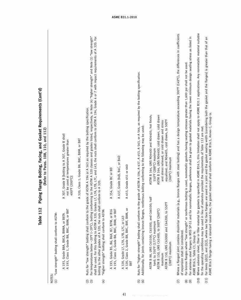
ASME B31.1-2010
Tabl
e11
2Pi
ping
Flan
geB
olti
ng,
Faci
ng,
and
Gas
ket
Requ
irem
ents
(Con
t’d)
(Ref
erto
Para
s.10
8,11
0,an
d11
2)
NO
TES
:(1
)“L
owst
reng
th”
bolt
ing
shal
lco
nfor
mto
AST
M:
A19
3,G
rade
B8A
,B
8CA
,B
8MA
,or
B8T
AA
307,
Gra
deB
[bol
ting
toA
307,
Gra
deB
shal
lA
193,
Clas
s1,
Gra
deB
8,B
8C,
B8M
,or
B8T
not
beus
edat
tem
pera
ture
sgr
eate
rth
an40
0°F
(200
°C)]
A32
0,Cl
ass
1,G
rade
B8,
B8C
,B
8M,
orB
8T
(2)
Nut
sfo
r“l
owst
reng
th”
bolt
ing
shal
lco
nfor
mto
the
grad
eof
AST
MA
194
orA
563
asre
quir
edby
the
bolt
ing
spec
ifica
tion
.(3
)Fo
rte
mpe
ratu
res
belo
w−
20°F
(−29
°C),
bolt
ing
conf
orm
ing
toth
eA
STM
A32
0cl
asse
san
dgr
ades
liste
d,re
spec
tive
ly,
inN
ote
(4)
“hig
her
stre
ngth
”an
dN
ote
(1)
“low
stre
ngth
”sh
all
beus
ed.
For
this
bolt
ing
toA
STM
A32
0,G
rade
sL7
,L7
A,
L7B
,L7
C,an
dL4
3,th
enu
tssh
all
conf
orm
toA
STM
A19
4,G
rade
4or
7w
ith
impa
ctre
quir
emen
tsof
A32
0.Fo
rbo
ltin
gto
the
othe
rgr
ades
ofA
320,
the
nuts
shal
lco
nfor
mto
A32
0.(4
)“H
ighe
rst
reng
th”
bolt
ing
shal
lco
nfor
mto
AST
M:
A19
3,G
rade
B5,
B6,
B6X
,B
7,B
7M,
orB
16A
354,
Gra
deB
Cor
BD
A19
3,Cl
ass
2,G
rade
B8,
B8C
,B
8M,
orB
8TA
437,
Gra
deB
4B,
B4C
,or
B4D
A32
0,G
rade
L7,
L7A
,L7
B,
L7C,
orL4
3A
320,
Clas
s2,
Gra
deB
8,B
8C,
B8F
,B
8M,
orA
453,
Gra
de65
1or
660
B8T
(5)
Nut
sfo
r“h
ighe
rst
reng
th”
bolt
ing
shal
lco
nfor
mto
the
grad
eof
AST
MA
194,
A43
7,A
453,
A56
3,or
A56
4,as
requ
ired
byth
ebo
ltin
gsp
ecifi
cati
on.
(6)
Add
itio
nally
,fo
rjo
ints
cont
aini
ngbr
onze
flang
es,
nonf
erro
usbo
ltin
gco
nfor
min
gto
the
follo
win
gm
aybe
used
:
AST
MB
98,
UN
SC6
5100
,C6
5500
,an
dC6
6100
;ha
lfA
STM
B16
4,U
NS
N04
400
and
N04
405;
hot
finis
h;ha
rd;
to35
0°F
(177
°C)
max
imum
550°
F(2
88°C
)m
axim
umA
STM
B15
0,U
NS
C614
00,
to50
0°F
(260
°C)
AST
MB
164,
UN
SN
0440
0,co
lddr
awn,
cold
draw
nm
axim
uman
dst
ress
relie
ved,
orco
lddr
awn
and
stre
ssA
STM
B15
0,U
NS
C630
00an
dC6
4200
,to
550°
Feq
ualiz
ed;
and
N04
405,
cold
draw
n,to
500°
F(2
88°C
)m
axim
um(2
60°C
)m
axim
um
(7)
Whe
rea
flang
edjo
int
cont
ains
diss
imila
rm
ater
ials
(e.g
.,br
onze
flang
esw
ith
stee
lbo
ltin
g)an
dha
sa
desi
gnte
mpe
ratu
reex
ceed
ing
300°
F(1
49°C
),th
edi
ffer
ence
sin
coef
ficie
nts
ofex
pans
ion
shal
lbe
cons
ider
ed.
(8)
For
bron
zefla
nges
whe
re“l
owst
reng
th”
orno
nfer
rous
bolt
ing
isus
ed,
nonm
etal
licga
sket
sha
ving
seat
ing
stre
sses
grea
ter
than
1,60
0ps
ish
all
not
beus
ed.
(9)
For
stai
nles
sst
eel
flang
esto
MSS
SP-
51an
dfo
rno
nmet
allic
flang
es,
pref
eren
cesh
all
begi
ven
toga
sket
mat
eria
lsha
ving
the
low
erm
inim
umde
sign
seat
ing
stre
ssas
liste
din
ASM
EB
16.5
,Ta
ble
C1,
Gro
upIa
.(1
0)W
here
asbe
stos
shee
t,fib
eror
fille
rm
ater
ial
for
gask
ets
issp
ecifi
edin
ASM
EB
16.5
,th
islim
itati
onsh
all
not
appl
yto
ASM
EB
31.1
appl
icat
ions
.A
nyno
nmet
allic
mat
eria
lsu
itabl
efo
rth
eop
erat
ing
cond
itio
nsm
aybe
used
inlie
uof
asbe
stos
prov
ided
the
requ
irem
ents
ofTa
ble
112
are
met
.(1
1)Fo
rit
ems
(d)(
2),
and
(i)(
2),
whe
retw
ofla
tfa
cefla
nges
are
used
ina
join
tan
dth
ega
sket
seat
ing
wid
th(c
onsi
deri
ngbo
thth
ega
sket
and
the
flang
es)
isgr
eate
rth
anth
atof
anA
SME
B16
.5fla
nge
havi
nga
stan
dard
rais
edfa
ce,
the
gask
etm
ater
ial
shal
lco
nfor
mto
ASM
EB
16.5
,A
nnex
C,G
roup
Ia.
41
Copyright ASME International Provided by IHS under license with ASME No reproduction or networking permitted without license from IHS
--`,,```````,,```,`,`,,,,`,`,`,`-`-`,,`,,`,`,,`---
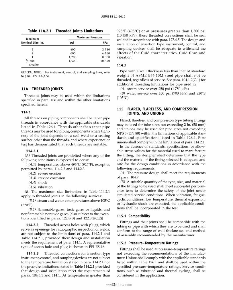
ASME B31.1-2010
Table 114.2.1 Threaded Joints Limitations
Maximum PressureMaximumNominal Size, in. psi kPa
3 400 2 7502 600 4 1501 1,200 8 300
3⁄4 and 1,500 10 350smaller
GENERAL NOTE: For instrument, control, and sampling lines, referto para. 122.3.6(A.5).
114 THREADED JOINTS
Threaded joints may be used within the limitationsspecified in para. 106 and within the other limitationsspecified herein.
114.1
All threads on piping components shall be taper pipethreads in accordance with the applicable standardslisted in Table 126.1. Threads other than taper pipethreads may be used for piping components where tight-ness of the joint depends on a seal weld or a seatingsurface other than the threads, and where experience ortest has demonstrated that such threads are suitable.
114.2.1(A) Threaded joints are prohibited where any of the
following conditions is expected to occur:(A.1) temperatures above 496°C (925°F), except as
permitted by paras. 114.2.2 and 114.2.3(A.2) severe erosion(A.3) crevice corrosion(A.4) shock(A.5) vibration
(B) The maximum size limitations in Table 114.2.1apply to threaded joints in the following services:
(B.1) steam and water at temperatures above 105°C(220°F)
(B.2) flammable gases, toxic gases or liquids, andnonflammable nontoxic gases [also subject to the excep-tions identified in paras. 122.8(B) and 122.8.2(C.2)]
114.2.2 Threaded access holes with plugs, whichserve as openings for radiographic inspection of welds,are not subject to the limitations of para. 114.2.1 andTable 114.2.1, provided their design and installationmeets the requirement of para. 114.1. A representativetype of access hole and plug is shown in PFI ES-16.
114.2.3 Threaded connections for insertion typeinstrument, control, and sampling devices are not subjectto the temperature limitation stated in para. 114.2.1 northe pressure limitations stated in Table 114.2.1 providedthat design and installation meet the requirements ofparas. 104.3.1 and 114.1. At temperatures greater than
42
925°F (495°C) or at pressures greater than 1,500 psi(10 350 kPa), these threaded connections shall be sealwelded in accordance with para. 127.4.5. The design andinstallation of insertion type instrument, control, andsampling devices shall be adequate to withstand theeffects of the fluid characteristics, fluid flow, andvibration.
114.3
Pipe with a wall thickness less than that of standardweight of ASME B36.10M steel pipe shall not bethreaded, regardless of service. See para. 104.1.2(C.1) foradditional threading limitations for pipe used in
(A) steam service over 250 psi (1 750 kPa)(B) water service over 100 psi (700 kPa) and 220°F
(105°C)
115 FLARED, FLARELESS, AND COMPRESSIONJOINTS, AND UNIONS
Flared, flareless, and compression type tubing fittingsmay be used for tube sizes not exceeding 2 in. (50 mm)and unions may be used for pipe sizes not exceedingNPS 3 (DN 80) within the limitations of applicable stan-dards and specifications listed in Table 126.1. Pipeunions shall comply with the limitations of para. 114.2.1.
In the absence of standards, specifications, or allow-able stress values for the material used to manufacturethe fitting, the designer shall determine that the typeand the material of the fitting selected is adequate andsafe for the design conditions in accordance with thefollowing requirements:
(A) The pressure design shall meet the requirementsof para. 104.7.
(B) A suitable quantity of the type, size, and materialof the fittings to be used shall meet successful perform-ance tests to determine the safety of the joint undersimulated service conditions. When vibration, fatigue,cyclic conditions, low temperature, thermal expansion,or hydraulic shock are expected, the applicable condi-tions shall be incorporated in the test.
115.1 Compatibility
Fittings and their joints shall be compatible with thetubing or pipe with which they are to be used and shallconform to the range of wall thicknesses and methodof assembly recommended by the manufacturer.
115.2 Pressure–Temperature Ratings
Fittings shall be used at pressure–temperature ratingsnot exceeding the recommendations of the manufac-turer. Unions shall comply with the applicable standardslisted within Table 126.1 and shall be used within thespecified pressure–temperature ratings. Service condi-tions, such as vibration and thermal cycling, shall beconsidered in the application.
Copyright ASME International Provided by IHS under license with ASME No reproduction or networking permitted without license from IHS
--`,,```````,,```,`,`,,,,`,`,`,`-`-`,,`,,`,`,,`---
标准分享网 www.bzfxw.com 免费下载

ASME B31.1-2010
115.3 Threads
See para. 114.1 for requirements of threads on pipingcomponents.
115.4 Fitting and Gripping
Flareless fittings shall be of a design in which thegripping member or sleeve shall grip or bite into theouter surface of the tube with sufficient strength to holdthe tube against pressure, but without appreciably dis-torting the inside tube diameter. The gripping membershall also form a pressure seal against the fitting body.
When using bite type fittings, a spot check shall bemade for adequate depth of bite and condition of tubingby disassembling and reassembling selected joints.
Grip-type fittings that are tightened in accordancewith manufacturer’s instructions need not be disassem-bled for checking.
116 BELL END JOINTS
116.1 Elastomeric-Gasket Joints
Elastomeric-gasket bell end joints may be used forwater and other nonflammable, nontoxic service whereexperience or tests have demonstrated that the joint issafe for the operating conditions and the fluid beingtransported. Provisions shall be made to prevent disen-gagement of the joints at bends and dead ends, and tosupport lateral reactions produced by branch connec-tions or other causes.
116.2 Caulked Joints
Caulked joints, if used, shall be restricted to cold waterservice, shall not use lead as the caulking material inpotable water service, and shall be qualified as speciallydesigned components in accordance with para. 104.7.2.Provisions shall be made to prevent disengagement ofthe joints at bends and dead ends, and to support lateralreactions produced by branch connections or othercauses.
117 BRAZED AND SOLDERED JOINTS
117.1 Brazed Joints
Brazed socket-type joints shall be made with suitablebrazing alloys. The minimum socket depth shall be suffi-cient for the intended service. Brazing alloy shall eitherbe end-fed into the socket or shall be provided in theform of a preinserted ring in a groove in the socket. Thebrazing alloy shall be sufficient to fill completely theannular clearance between the socket and the pipe ortube. The limitations of paras. 117.3(A) and (D) shallapply.
117.2 Soldered Joints
Soft soldered socket-type joints made in accordancewith applicable standards listed in Table 126.1 may be
43
used within their specified pressure–temperature rat-ings. The limitations in paras. 117.3 and 122.3.2(E.2.3)for instrument piping shall apply. The allowances ofpara. 102.2.4 do not apply.
117.3 Limitations
(A) Brazed socket-type joints shall not be used onsystems containing flammable or toxic fluids in areaswhere fire hazards are involved.
(B) Soldered socket-type joints shall be limited to sys-tems containing nonflammable and nontoxic fluids.
(C) Soldered socket-type joints shall not be used inpiping subject to shock or vibration.
(D) Brazed or soldered joints depending solely upona fillet, rather than primarily upon brazing or solderingmaterial between the pipe and sockets, are notacceptable.
118 SLEEVE COUPLED AND OTHER PROPRIETARYJOINTS
Coupling type, mechanical gland type, and other pro-prietary joints may be used where experience or testshave demonstrated that the joint is safe for the operatingconditions, and where adequate provision is made toprevent separation of the joint.
PART 5EXPANSION, FLEXIBILITY, AND PIPE SUPPORTING
ELEMENT
119 EXPANSION AND FLEXIBILITY
119.1 General
In addition to the design requirements for pressure,weight, and other sustained or occasional loadings (seeparas. 104.1 through 104.7, 104.8.1, and 104.8.2), powerpiping systems subject to thermal expansion, contrac-tion, or other displacement stress producing loads shallbe designed in accordance with the flexibility and dis-placement stress requirements specified herein.
119.2 Displacement Stress Range
Piping system stresses caused by thermal expansionand piping displacements, referred to as displacementstresses, when of sufficient initial magnitude during sys-tem startup or extreme displacements, relax in the maxi-mum stress condition as the result of local yielding orcreep. A stress reduction takes place and usually appearsas a stress of reversed sign when the piping systemreturns to the cold condition for thermal loads or theneutral position for extreme displacement loads. Thisphenomenon is designated as self-springing (or shake-down) of the piping and is similar in effect to coldspringing. The extent of self-springing depends uponthe material, the magnitude of the displacement stresses,the fabrication stresses, the hot service temperature, and
Copyright ASME International Provided by IHS under license with ASME No reproduction or networking permitted without license from IHS
--`,,```````,,```,`,`,,,,`,`,`,`-`-`,,`,,`,`,,`---

ASME B31.1-2010
the elapsed time. While the displacement stresses in thehot or displaced condition tend to diminish with timeand yielding, the sum of the displacement strains forthe maximum and minimum stress conditions duringany one cycle remains substantially constant. This sumis referred to as the strain range. However, to simplifythe evaluation process, the strain range is converted toa stress range to permit the more usual association withan allowable stress range. The allowable stress rangeshall be as determined in accordance withpara. 102.3.2(B).
119.3 Local Overstrain
Most of the commonly used methods of piping flexibil-ity and cyclic stress analysis assume elastic or partlyelastic behavior of the entire piping system. Thisassumption is sufficiently accurate for systems whereplastic straining occurs at many points or over relativelywide regions, but fails to reflect the actual strain distribu-tion in unbalanced systems where only a small portion ofthe piping undergoes plastic strain, or where, in pipingoperating in the creep range, the strain distribution isvery uneven. In these cases, the weaker or higherstressed portions will be subjected to strain concentra-tions due to elastic follow-up of the stiffer or lowerstressed portions. Unbalance can be produced
(A) by use of small pipe runs in series with larger orstiffer pipe, with the small lines relatively highly stressed
(B) by local reduction in size or cross section, or localuse of a weaker material
(C) in a system of uniform size, by use of a line config-uration for which the neutral axis or thrust line is situ-ated close to the major portion of the line itself, withonly a very small offset portion of the line absorbingmost of the expansion strain
Conditions of this type should preferably be avoided,particularly where materials of relatively low ductilityare used.
119.5 Flexibility
Power piping systems shall be designed to have suffi-cient flexibility to prevent piping displacements fromcausing failure from overstress of the piping compo-nents, overloading of anchors and other supports, leak-age at joints, or detrimental distortion of connectedequipment. Flexibility shall be provided by changes indirection in the piping through the use of fittings, bends,loops, and offsets. When piping bends, loops, and offsetsare not able to provide adequate flexibility, provisionsmay be made to absorb piping displacements by utiliz-ing expansion, swivel, or ball joints, or flexible metalhose assemblies.
119.5.1 Expansion, Swivel, or Ball Joints, and FlexibleMetal Hose Assemblies. Except as stated in para.101.7.2, these components may be used where experi-ence or tests have demonstrated that they are suitable
44
for expected conditions of pressure, temperature, ser-vice, and cyclic life.
Restraints and supports shall be provided, as required,to limit movements to those directions and magnitudespermitted for the specific joint or hose assembly selected.
119.6 Piping Properties
The coefficient of thermal expansion and moduli ofelasticity shall be determined from Appendices B andC, which cover more commonly used piping materials.For materials not included in those Appendices, refer-ence shall be to authoritative source data such as publi-cations of the National Institute of Standards andTechnology.
119.6.1 Coefficient of Thermal Expansion. The coef-ficient of thermal expansion shall be determined fromvalues given in Appendix B. The coefficient used shallbe based on the highest average operating metal temper-ature and the lowest ambient metal temperature, unlessother temperatures are justified. Appendix B values arebased on the assumption that the lowest ambient metaltemperature is 70°F (20°C). If the lowest metal tempera-ture of a thermal range to be evaluated is not 70°F (20°C),adjustment of the values in Appendix B may be required.
119.6.2 Moduli of Elasticity. The cold and hot mod-uli of elasticity, Ec and Eh, shall be as shown inAppendix C, Table C-1 for ferrous materials andTable C-2 for nonferrous materials, based on the temper-atures established in para. 119.6.1.
119.6.3 Poisson’s Ratio. Poisson’s ratio, whenrequired for flexibility calculations, shall be taken as 0.3at all temperatures for all materials.
119.6.4 Stresses. Calculations for the stresses shallbe based on the least cross section area of the component,using nominal dimensions at the location under consid-eration. Calculation for the reference displacement stressrange, SE, shall be based on the modulus of elasticity,Ec, at room temperature, unless otherwise justified.
119.7 Flexibility Analysis
119.7.1 Method of Analysis. All piping shall meetthe following requirements with respect to flexibility:
(A) It shall be the designer’s responsibility to performan analysis unless the system meets one of the followingcriteria:
(A.1) The piping system duplicates a successfullyoperating installation or replaces a system with a satis-factory service record.
(A.2) The piping system can be adjudged adequateby comparison with previously analyzed systems.
(A.3) The piping system is of uniform size, has notmore than two anchors and no intermediate restraints,is designed for essentially noncyclic service (less than7,000 total cycles), and satisfies the following approxi-mate criterion:
Copyright ASME International Provided by IHS under license with ASME No reproduction or networking permitted without license from IHS
--`,,```````,,```,`,`,,,,`,`,`,`-`-`,,`,,`,`,,`---
标准分享网 www.bzfxw.com 免费下载

ASME B31.1-2010
U.S. Customary Units
DY
(L − U)2≤ 30
SA
Ec
SI Units
DY
(L − U)2≤ 208 000
SA
Ec
whereD p nominal pipe size (NPS), in. (mm)Ec p modulus of elasticity at room temperature,
psi (kPa)L p developed length of pipe (total length of pipe
taken along the piping longitudinal axes), ft(m)
SA p allowable displacement stress range deter-mined in accordance with para. 102.3.2(B),eq. (1A), psi (kPa)
U p anchor distance (length of straight line betweenthe anchors), ft (m)
Y p resultant displacement between the anchors tobe absorbed by the piping system, in. (mm)
WARNING: No general proof can be offered that this equationwill yield accurate or consistently conservative results. It wasdeveloped for ferrous materials and is not applicable to systemsused under severe cyclic conditions. It should be used with cau-tion in configurations such as unequal leg U-bends (L/U > 2.5),or near straight “saw-tooth” runs, or for large diameter thin-wallpipe, or where extraneous displacements (not in the directionconnecting anchor points) constitute a large part of the totaldisplacement, or where piping operates in the creep range. Thereis no assurance that anchor reactions will be acceptably low, evenwhen a piping system meets the above requirements.
(B) All systems not meeting the above criteria, orwhere reasonable doubt exists as to adequate flexibilitybetween the anchors, shall be analyzed by simplified,approximate, or comprehensive methods of analysis thatare appropriate for the specific case. The results of suchanalysis shall be evaluated using para. 104.8.3, eq. (17).
(C) Approximate or simplified methods may beapplied only if they are used for the range of configura-tions for which their adequate accuracy has beendemonstrated.
(D) Acceptable comprehensive methods of analysisinclude: analytical, model tests, and chart methods thatprovide an evaluation of the forces, moments, andstresses caused by bending and torsion from the simulta-neous consideration of terminal and intermediaterestraints to thermal expansion of the entire piping sys-tem under consideration, and including all externalmovements transmitted to the piping by its terminaland intermediate attachments. Correction factors shallbe applied for the stress intensification of curved pipeand branch connections, as provided by the details ofthese rules, and may be applied for the increased flexibil-ity of such component parts.
45
119.7.3 Basic Assumptions and Requirements. Incalculating the flexibility or displacement stresses of apiping system between anchor points, the systembetween anchor points shall be treated as a whole. Thesignificance of all parts of the line and of all restraints,such as supports or guides, including intermediaterestraints introduced for reducing moments and forceson equipment or small branch lines, shall be considered.
Flexibility calculations shall take into account stressintensifying conditions found in components and joints.Credit may be taken when extra flexibility exists in suchcomponents. In the absence of more directly applicabledata, the flexibility factors and stress-intensification fac-tors shown in Appendix D may be used.4
Dimensional properties of pipe and fittings used inflexibility calculations shall be based on nominaldimensions.
The total reference displacement range resulting fromusing the coefficient of thermal expansion determinedin accordance with para. 119.6.1 shall be used, whetheror not the piping is cold sprung. Not only the expansionof the line itself, but also linear and angular movementsof the equipment to which it is attached, shall beconsidered.
Where simplifying assumptions are used in calcula-tions or model tests, the likelihood of attendant underes-timates of forces, moments, and stresses, including theeffects of stress intensification, shall be evaluated.
119.8 Movements
Movements caused by thermal expansion and load-ings shall be determined for consideration of obstruc-tions and design of proper supports.
119.9 Cold Spring
The beneficial effect of judicious cold springing inassisting a system to attain its most favorable positionsooner is recognized. Inasmuch as the life of a systemunder cyclic conditions depends on the stress rangerather than the stress level at any one time, no creditfor cold spring is allowed with regard to stresses. Incalculating end thrusts and moments acting on equip-ment, the actual reactions at any one time, rather thantheir range, are significant. Credit for cold springing isaccordingly allowed in the calculation of thrusts andmoments, provided an effective method of obtaining thedesigned cold spring is specified and used.
4 The stress-intensification factors in Appendix D have beendeveloped from fatigue tests of representative commercially avail-able, matching product forms and assemblies manufactured fromductile ferrous materials. The allowable stress range is based ontests of carbon and stainless steels. Caution should be exercisedwhen applying Figs. (1) and (13) for the allowable stress range forcertain nonferrous materials (e.g., copper and aluminum alloys)for other than low cycle applications.
Copyright ASME International Provided by IHS under license with ASME No reproduction or networking permitted without license from IHS
--`,,```````,,```,`,`,,,,`,`,`,`-`-`,,`,,`,`,,`---

ASME B31.1-2010
119.10 Reactions
119.10.1 Computing Hot and Cold Reactions. In apiping system with no cold spring or an equal percent-age of cold springing in all directions, the reactions(forces and moments) of Rh and Rc, in the hot and coldconditions, respectively, shall be obtained from the reac-tion, R, derived from the flexibility calculations basedon the modulus of elasticity at room temperature, Ec,using eqs. (18) and (19).
Rh p �1 − 2/3C� �Eh
EcR� (18)
Rc p − CR, or
(19)p − �1 −(Sh)(SE)
W
(Ec)(Eh)� R
whichever is greater, and with the further condition that
(Sh)(SE)
W
(Ec)(Eh)
< 1
whereC p cold spring factor varying from zero for no
cold spring to 1.00 for 100% cold springEc p modulus of elasticity in the cold condition,
psi (MPa)Eh p modulus of elasticity in the hot condition,
psi (MPa)R p maximum reaction for full expansion range
based on Ec, which assumes the most severecondition (100% cold spring, whether suchis used or not), lb and in.-lb (N and mm·N)
Rc, Rh p maximum reactions estimated to occur inthe cold and hot conditions, respectively, lband in.-lb (N and mm·N)
SE p computed thermal expansion stress range,psi (MPa)
Sh p basic material allowable stress at maximum(hot) temperature, without the 20 ksi limita-tion as noted in para. 102.3.2(C)
If a piping system is designed with different percent-ages of cold spring in various directions, eqs. (18) and(19) are not applicable. In this case, the piping systemshall be analyzed by a comprehensive method. The cal-culated hot reactions shall be based on theoretical coldsprings in all directions not greater than two-thirds ofthe cold springs as specified or measured.
119.10.2 Reaction Limits. The reactions computedshall not exceed limits that the attached equipment cansustain. Equipment allowable reaction limits (forces andmoments) on piping connections are normally estab-lished by the equipment manufacturer.
46
120 LOADS ON PIPE SUPPORTING ELEMENTS
120.1 General
(A) The broad terms “supporting elements” or “sup-ports” as used herein shall encompass the entire rangeof the various methods of carrying the weight of pipelines, insulation, and the fluid carried. It, therefore,includes “hangers” that are generally considered asthose elements that carry the weight from above, withthe supporting members being mainly in tension. Like-wise, it includes “supports” that on occasion are deline-ated as those that carry the weight from below, with thesupporting members being mainly in compression. Inmany cases a supporting element may be a combinationof both of these.
(B) In addition to the weight effects of piping compo-nents, consideration shall be given in the design of pipesupports to other load effects introduced by service pres-sure, wind, earthquake, etc., as defined in para. 101.Hangers and supporting elements shall be fabricatedand assembled to permit the free movement of pipingcaused by thermal expansion and contraction. Thedesign of elements for supporting or restraining pipingsystems, or components thereof, shall be based on allthe concurrently acting loads transmitted into the sup-porting elements.
(C) Where the resonance with imposed vibrationand/or shock occurs during operation, suitable damp-eners, restraints, anchors, etc., shall be added to removethese effects.
120.2 Supports, Anchors, and Guides
120.2.1 Rigid-Type Supports(A) The required strength of all supporting elements
shall be based on the loadings as given in para. 120.1,including the weight of the fluid transported or the fluidused for testing, whichever is heavier. The allowablestress in supporting equipment shall be as specified inpara. 121.2.
(B) Exceptions may be made in the case of supportingelements for large size gas or air piping, exhaust steam,relief or safety valve relief piping, but only under theconditions where the possibility of the line becomingfull of water or other liquid is very remote.
120.2.2 Variable and Constant Supports. Load cal-culations for variable and constant supports, such assprings or counterweights, shall be based on the designoperating conditions of the piping. They shall notinclude the weight of the hydrostatic test fluid. However,the support shall be capable of carrying the total loadunder test conditions, unless additional support is pro-vided during the test period.
120.2.3 Anchors or Guides. Where anchors orguides are provided to restrain, direct, or absorb pipingmovements, their design shall take into account the
Copyright ASME International Provided by IHS under license with ASME No reproduction or networking permitted without license from IHS
--`,,```````,,```,`,`,,,,`,`,`,`-`-`,,`,,`,`,,`---
标准分享网 www.bzfxw.com 免费下载

(10)
ASME B31.1-2010
forces and moments at these elements caused by internalpressure and thermal expansion.
120.2.4 Supplementary Steel. Where it is necessaryto frame structural members between existing steelmembers, such supplementary steel shall be designedin accordance with American Institute of SteelConstruction specifications, or similar recognized struc-tural design standards. Increases of allowable stress val-ues shall be in accordance with the structural designstandard being used. Additional increases of allowablestress values, such as allowed in para. 121.2(I), are notpermitted.
121 DESIGN OF PIPE SUPPORTING ELEMENTS
121.1 General
Design of standard pipe supporting elements shall bein accordance with the rules of MSS SP-58. Allowablestress values and other design criteria shall be in accor-dance with this paragraph. Supporting elements shallbe capable of carrying the sum of all concurrently actingloads as listed in para. 120. They shall be designed toprovide the required supporting effort and allow pipe-line movement with thermal changes without causingoverstress. The design shall also prevent completerelease of the piping load in the event of spring failureor misalignment. All parts of the supporting equipmentshall be fabricated and assembled so that they will notbe disengaged by movement of the supported piping.The maximum safe loads for bolts, threaded hanger rods,and all other threaded members shall be based on theroot area of the threads. MSS SP-69 may be used forguidance with respect to selection and application ofpipe hangers and supports.
121.2 Allowable Stress Values
(A) Allowable stress values tabulated in MSS SP-58or in Appendix A of this Code Section may be usedfor the base materials of all parts of pipe supportingelements.
(B) Where allowable stress values for a material speci-fication listed in Table 126.1 are not tabulated inAppendix A or in MSS SP-58, allowable stress valuesfrom Section II, Part D, Tables 1A and 1B of the ASMEBoiler and Pressure Vessel Code may be used, providedthe requirements of para. 102.3.1(B) are met. Where thereare no stress values given in Section II, Part D, Tables 1Aand 1B, an allowable stress value of 25% of the minimumtensile strength given in the material specification maybe used, for temperatures not exceeding 650°F (345°C).
(C) For a steel material of unknown specification, orof a specification not listed in Table 126.1 or MSS SP-58,an allowable stress value of 30% of yield strength (0.2%offset) at room temperature may be used at temperaturesnot exceeding 650°F (345°C). The yield strength shall bedetermined through a tensile test of a specimen of the
47
material and shall be the value corresponding to 0.2%permanent strain (offset) of the specimen. The allowablestress values for such materials shall not exceed 9,500 psi(65.5 MPa).
(D) The allowable shear stress shall not exceed 80%of the values determined in accordance with the rulesof (A), (B), and (C) above.
(E) The allowable compressive stress shall not exceedthe value as determined in accordance with the rules of(A), (B), or (C) above. In addition, consideration shallbe given to structural stability.
(F) The allowable bearing stress shall not exceed 160%of the value as determined in accordance with the rulesof (A), (B), or (C) above.
(G) The allowable stress in tension determined from(A), (B), or (C) above shall be reduced 25% for threadedhanger rods.
(H) The allowable stress in partial penetration or filletwelds in support assemblies shall be reduced 25% fromthose determined in accordance with (A), (B), (C), or(D) above for the weaker of the two metals joined.
(I) If materials for attachments have different allow-able stress values than the pipe, then the allowable stressfor the weld shall be based on the lower allowable stressof the materials being joined.
(J) Increases in the allowable stress values shall bepermitted as follows:
(J.1) an increase of 20% for short time overloadingduring operation.
(J.2) an increase to 80% of the minimum yieldstrength at room temperature during hydrostatic testing.Where the material allowable stress has been establishedin accordance with the rules of (C) above, the allowablestress value during hydrostatic testing shall not exceed16,000 psi (110.3 MPa).
121.3 Temperature Limitations
Parts of supporting elements that are subjected princi-pally to bending or tension loads and that are subjectedto working temperatures for which carbon steel is notrecommended shall be made of suitable alloy steel, orshall be protected so that the temperature of the support-ing member will be maintained within the appropriatetemperature limits of the material.
121.4 Hanger Adjustments
Hangers used for the support of piping, NPS 21⁄2 andlarger, shall be designed to permit adjustment after erec-tion while supporting the load. Screwed adjustmentsshall have threaded parts to conform to ASME B1.1.
Class 2 fit turnbuckles and adjusting nuts shall havethe full length of thread in engagement. Means shall beprovided for determining that full thread length is inengagement. All screw and equivalent adjustments shallbe provided with suitable locking devices.
Copyright ASME International Provided by IHS under license with ASME No reproduction or networking permitted without license from IHS
--`,,```````,,```,`,`,,,,`,`,`,`-`-`,,`,,`,`,,`---

ASME B31.1-2010
Table 121.5 Suggested Pipe Support Spacing
Suggested Maximum Span
Water Steam, Gas,NominalService or Air ServicePipe Size,
NPS ft m ft m
1 7 2.1 9 2.72 10 3.0 13 4.03 12 3.7 15 4.64 14 4.3 17 5.26 17 5.2 21 6.4
8 19 5.8 24 7.312 23 7.0 30 9.116 27 8.2 35 10.720 30 9.1 39 11.924 32 9.8 42 12.8
GENERAL NOTES:(a) Suggested maximum spacing between pipe supports for hori-
zontal straight runs of standard and heavier pipe at maximumoperating temperature of 750°F (400°C).
(b) Does not apply where span calculations are made or wherethere are concentrated loads between supports, such asflanges, valves, specialties, etc.
(c) The spacing is based on a fixed beam support with a bendingstress not exceeding 2,300 psi (15.86 MPa) and insulated pipefilled with water or the equivalent weight of steel pipe forsteam, gas, or air service, and the pitch of the line is suchthat a sag of 0.1 in. (2.5 mm) between supports ispermissible.
121.5 Hanger Spacing
Supports for piping with the longitudinal axis inapproximately a horizontal position shall be spaced toprevent excessive sag, bending and shear stresses in thepiping, with special consideration given where compo-nents, such as flanges and valves, impose concentratedloads. Where calculations are not made, suggested maxi-mum spacing of supports for standard and heavier pipeare given in Table 121.5. Vertical supports shall be spacedto prevent the pipe from being overstressed from thecombination of all loading effects.
121.6 Springs
The springs used in variable or constant effort typesupports shall be designed and manufactured in accor-dance with MSS SP-58.
121.7 Fixtures
121.7.1 Anchors and Guides(A) Anchors, guides, pivots, and restraints shall be
designed to secure the desired points of piping in rela-tively fixed positions. They shall permit the piping toexpand and contract freely in directions away from theanchored or guided point and shall be structurally suit-able to withstand the thrusts, moments, and other loadsimposed.
48
(B) Rolling or sliding supports shall permit free move-ment of the piping, or the piping shall be designed toinclude the imposed load and frictional resistance ofthese types of supports, and dimensions shall providefor the expected movement of the supported piping.Materials and lubricants used in sliding supports shallbe suitable for the metal temperature at the point ofsliding contact.
(C) Where corrugated or slip-type expansion joints,or flexible metal hose assemblies are used, anchors andguides shall be provided where necessary to direct theexpansion into the joint or hose assembly. Such anchorsshall be designed to withstand the force specified bythe manufacturer for the design conditions at which thejoint or hose assembly is to be used. If this force isotherwise unknown, it shall be taken as the sum of theproduct of the maximum internal area times the designpressure plus the force required to deflect the joint orhose assembly. Where expansion joints or flexible metalhose assemblies are subjected to a combination of longi-tudinal and transverse movements, both movementsshall be considered in the design and application of thejoint or hose assembly.
Flexible metal hose assemblies, applied in accordancewith para. 106.4, shall be supported in such a manneras to be free from any effects due to torsion and unduestrain as recommended by the manufacturer.
121.7.2 Other Rigid Types(A) Hanger Rods. Safe loads for threaded hanger rods
shall be based on the root area of the threads and 75%of the allowable stress of the material as provided inpara. 121.2(G). In no case shall hanger rods less than3⁄8 in. (9.5 mm) diameter be used for support of pipeNPS 2 and smaller, or less than 1⁄2 in. (12.5 mm) diameterrod for supporting pipe NPS 21⁄2 and larger. SeeTable 121.7.2(A) for carbon steel rods.
Pipe, straps, or bars of strength and effective area equalto the equivalent hanger rod may be used instead ofhanger rods.
Hanger rods, straps, etc., shall be designed to permitthe free movement of piping caused by thermal expan-sion and contraction.
(B) Welded link chain of 3⁄16 in. (5.0 mm) or largerdiameter stock, or equivalent area, may be used for pipehangers with a design stress of 9,000 psi (62 MPa)maximum.
(C) Cast iron in accordance with ASTM A 48 may beused for bases, rollers, anchors, and parts of supportswhere the loading will be mainly compression. Cast ironparts shall not be used in tension.
(D) Malleable iron castings in accordance withASTM A 47 may be used for pipe clamps, beam clamps,hanger flanges, clips, bases, swivel rings, and parts ofpipe supports, but their use shall be limited to tempera-tures not in excess of 450°F (230°C). This material is
Copyright ASME International Provided by IHS under license with ASME No reproduction or networking permitted without license from IHS
--`,,```````,,```,`,`,,,,`,`,`,`-`-`,,`,,`,`,,`---
标准分享网 www.bzfxw.com 免费下载
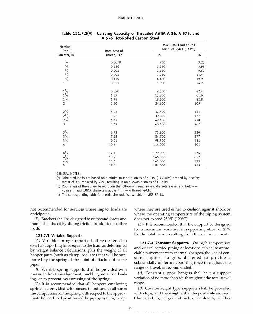
ASME B31.1-2010
Table 121.7.2(A) Carrying Capacity of Threaded ASTM A 36, A 575, andA 576 Hot-Rolled Carbon Steel
Max. Safe Load at RodNominalTemp. of 650°F (343°C)Rod Root Area of
Diameter, in. Thread, in.2 lb kN
3⁄8 0.0678 730 3.231⁄2 0.126 1,350 5.985⁄8 0.202 2,160 9.613⁄4 0.302 3,230 14.47⁄8 0.419 4,480 19.9
1 0.551 5,900 26.2
11⁄4 0.890 9,500 42.411⁄2 1.29 13,800 61.613⁄4 1.74 18,600 82.82 2.30 24,600 109
21⁄4 3.02 32,300 14421⁄2 3.72 39,800 17723⁄4 4.62 49,400 2203 5.62 60,100 267
31⁄4 6.72 71,900 32031⁄2 7.92 84,700 37733⁄4 9.21 98,500 4384 10.6 114,000 505
41⁄4 12.1 129,000 57641⁄2 13.7 146,000 65243⁄4 15.4 165,000 7335 17.2 184,000 819
GENERAL NOTES:(a) Tabulated loads are based on a minimum tensile stress of 50 ksi (345 MPa) divided by a safety
factor of 3.5, reduced by 25%, resulting in an allowable stress of 10.7 ksi.(b) Root areas of thread are based upon the following thread series: diameters 4 in. and below —
coarse thread (UNC); diameters above 4 in. — 4 thread (4-UN).(c) The corresponding table for metric size rods is available in MSS SP-58.
not recommended for services where impact loads areanticipated.
(E) Brackets shall be designed to withstand forces andmoments induced by sliding friction in addition to otherloads.
121.7.3 Variable Supports(A) Variable spring supports shall be designed to
exert a supporting force equal to the load, as determinedby weight balance calculations, plus the weight of allhanger parts (such as clamp, rod, etc.) that will be sup-ported by the spring at the point of attachment to thepipe.
(B) Variable spring supports shall be provided withmeans to limit misalignment, buckling, eccentric load-ing, or to prevent overstressing of the spring.
(C) It is recommended that all hangers employingsprings be provided with means to indicate at all timesthe compression of the spring with respect to the approx-imate hot and cold positions of the piping system, except
49
where they are used either to cushion against shock orwhere the operating temperature of the piping systemdoes not exceed 250°F (120°C).
(D) It is recommended that the support be designedfor a maximum variation in supporting effort of 25%for the total travel resulting from thermal movement.
121.7.4 Constant Supports. On high temperatureand critical service piping at locations subject to appre-ciable movement with thermal changes, the use of con-stant support hangers, designed to provide asubstantially uniform supporting force throughout therange of travel, is recommended.
(A) Constant support hangers shall have a supportvariation of no more than 6% throughout the total travelrange.
(B) Counterweight type supports shall be providedwith stops, and the weights shall be positively secured.Chains, cables, hanger and rocker arm details, or other
Copyright ASME International Provided by IHS under license with ASME No reproduction or networking permitted without license from IHS
--`,,```````,,```,`,`,,,,`,`,`,`-`-`,,`,,`,`,,`---

ASME B31.1-2010
devices used to attach the counterweight load to thepiping, shall be subject to requirements of para. 121.7.2.
(C) Hydraulic type supports utilizing a hydraulichead may be installed to give a constant supportingeffort. Safety devices and stops shall be provided tosupport the load in case of hydraulic failure.
(D) Boosters may be used to supplement the opera-tion of constant support hangers.
121.7.5 Sway Braces. Sway braces or vibrationdampeners shall be used to control the movement ofpiping due to vibration.
121.7.6 Shock Suppressors. For the control of pip-ing due to dynamic loads, hydraulic or mechanical typesof shock suppressors are permitted. These devices donot support pipe weight.
121.8 Structural Attachments
121.8.1 Nonintegral Type(A) Nonintegral attachments include clamps, slings,
cradles, saddles, straps, and clevises.(B) When clamps are used to support vertical lines,
it is recommended that shear lugs be welded to the pipeto prevent slippage. The provisions of para. 121.8.2(B)shall apply.
(C) In addition to the provision of (B) above, clampsto support vertical lines should be designed to supportthe total load on either arm in the event the load shiftsdue to pipe and/or hanger movement.
121.8.2 Integral Type(A) Integral attachments include ears, shoes, lugs,
cylindrical attachments, rings, and skirts that are fabri-cated so that the attachment is an integral part of thepiping component. Integral attachments shall be usedin conjunction with restraints or braces where multiaxialrestraint in a single member is to be maintained. Consid-eration shall be given to the localized stresses inducedinto the piping component by the integral attachments.Where applicable, the conditions of para. 121.8.1(C) areto apply.
(B) Integral lugs, plates, angle clips, etc., used as partof an assembly for the support or guiding of pipe maybe welded directly to the pipe provided the materialsare compatible for welding and the design is adequatefor the temperature and load. The design of hanger lugsfor attachment to piping for high temperature serviceshall be such as to provide for differential expansionbetween the pipe and the attached lug.
121.9 Loads and Supporting Structures
Considerations shall be given to the load carryingcapacity of equipment and the supporting structure.This may necessitate closer spacing of hangers on lineswith extremely high loads.
50
121.10 Requirements for Fabricating Pipe Supports
Pipe supports shall be fabricated in accordance withthe requirements of para. 130.
PART 6SYSTEMS
122 DESIGN REQUIREMENTS PERTAINING TOSPECIFIC PIPING SYSTEMS
Except as specifically stated otherwise in this Part 6,all provisions of the Code apply fully to the pipingsystems described herein.
122.1 Boiler External Piping; in Accordance WithPara. 100.1.2(A) — Steam, Feedwater, Blowoff,and Drain Piping
122.1.1 General. The minimum pressure and tem-perature and other special requirements to be used inthe design for steam, feedwater, blowoff, and drain pip-ing from the boiler to the valve or valves required bypara. 122.1 shall be as specified in the following para-graphs. Design requirements for desuperheater spraypiping connected to desuperheaters located in the boilerproper and in main steam piping are provided inpara. 122.4.
(A) It is intended that the design pressure and temper-ature be selected sufficiently in excess of any expectedoperating conditions, not necessarily continuous, to per-mit satisfactory operation without operation of the over-pressure protection devices. Also, since the operatingtemperatures of fired equipment can vary, the expectedtemperature at the connection to the fired equipmentshall include the manufacturer’s maximum temperaturetolerance.
(B) In a forced flow steam generator with no fixedsteam and water line, it is permissible to design theexternal piping, valves, and fittings attached to the pres-sure parts for different pressure levels along the paththrough the steam generator of water-steam flow. Thevalues of design pressure and the design temperatureto be used for the external piping, valves, and fittingsshall be not less than that required for the expectedmaximum sustained operating pressure and tempera-ture to which the abutted pressure part is subjectedexcept when one or more of the overpressure protectiondevices covered by PG-67.4 of Section I of the ASMEBoiler and Pressure Vessel Code is in operation. Thesteam piping shall comply with the requirements forthe maximum sustained operating conditions as usedin (A) above, or for the design throttle pressure plus 5%,whichever is greater.
(C) Provision shall be made for the expansion andcontraction of piping connected to boilers to limit forcesand moments transmitted to the boiler, by providingsubstantial anchorage at suitable points, so that thereshall be no undue strain transmitted to the boiler. Steam
Copyright ASME International Provided by IHS under license with ASME No reproduction or networking permitted without license from IHS
--`,,```````,,```,`,`,,,,`,`,`,`-`-`,,`,,`,`,,`---
标准分享网 www.bzfxw.com 免费下载

ASME B31.1-2010
reservoirs shall be used on steam mains when heavypulsations of the steam currents cause vibration.
(D) Piping connected to the outlet of a boiler for anypurpose shall be attached by
(D.1) welding to a nozzle or socket welding fitting(D.2) threading into a tapped opening with a
threaded fitting or valve at the other end(D.3) screwing each end into tapered flanges, fit-
tings, or valves with or without rolling or peening(D.4) bolted joints including those of the Van
Stone type(D.5) blowoff piping of firetube boilers shall be
attached in accordance with (D.2) above if exposed toproducts of combustion or in accordance with (D.2),(D.3), or (D.4) above if not so exposed
(E) Nonferrous pipe or tubes shall not exceed NPS 3in diameter.
(F) American National Standard slip-on flanges shallnot exceed NPS 4. Attachment of slip-on flanges shallbe by double fillet welds. The throats of the fillet weldsshall not be less than 0.7 times the thickness of the partto which the flange is attached.
(G) Hub-type flanges shall not be cut from platematerial.
(H) American National Standard socket weldedflanges may be used in piping or boiler nozzles providedthe dimensions do not exceed NPS 3 for Class 600 andlower and NPS 21⁄2 in Class 1500.
122.1.2 Steam Piping(A) The value of P to be used in the formulas in
para. 104 shall be as follows:(A.1) For steam piping connected to the steam
drum or to the superheater inlet header up to the firststop valve in each connection, the value of P shall benot less than the lowest pressure at which any drumsafety valve is set to blow, and the S value shall notexceed that permitted for the corresponding saturatedsteam temperature.
(A.2) For steam piping connected to the super-heater outlet header up to the first stop valve in eachconnection, the design pressure, except as otherwise pro-vided in (A.4) below shall be not less than the lowestpressure at which any safety valve on the superheateris set to blow, or not less than 85% of the lowest pressureat which any drum safety valve is set to blow, whicheveris greater, and the S value for the material used shallnot exceed that permitted for the expected steamtemperature.
(A.3) For steam piping between the first stop valveand the second valve, when one is required by para.122.1.7, the design pressure shall be not less than theexpected maximum sustained operating pressure or 85%of the lowest pressure at which any drum safety valveis set to blow, whichever is greater, and the S value forthe material used shall not exceed that permitted forthe expected steam temperature.
51
(A.4) For boilers installed on the unit system (i.e.,one boiler and one turbine or other prime mover) andprovided with automatic combustion control equipmentresponsive to steam header pressure, the design pressurefor the steam piping shall be not less than the designpressure at the throttle inlet plus 5%, or not less than85% of the lowest pressure at which any drum safetyvalve is set to blow, or not less than the expected maxi-mum sustained operating pressure at any point in thepiping system, whichever is greater, and the S value forthe material used shall not exceed that permitted forthe expected steam temperature at the superheater out-let. For forced-flow steam generators with no fixedsteam and water line, the design pressure shall also beno less than the expected maximum sustained operatingpressure.
(A.5) The design pressure shall not be taken at lessthan 100 psig [700 kPa (gage)] for any condition of ser-vice or material.
122.1.3 Feedwater Piping(A) The value of P to be used in the formulas in
para. 104 shall be as follows:(A.1) For piping from the boiler to and including
the required stop valve and the check valve, the mini-mum value of P except as permitted in para. 122.1.3(A.4)shall exceed the maximum allowable working pressureof the boiler by either 25% or 225 psi (1 550 kPa), which-ever is the lesser. For an installation with an integraleconomizer without valves between the boiler and econ-omizer, this paragraph shall apply only to the pipingfrom the economizer inlet header to and including therequired stop valve and the check valve.
(A.2) For piping between the required check valveand the globe or regulating valve, when required bypara. 122.1.7(B), and including any bypass piping up tothe shutoff valves in the bypass, the value of P shall benot less than the pressure required to feed the boiler.
(A.3) The value of P in the formula shall not betaken at less than 100 psig [700 kPa (gage)] for anycondition of service or material, and shall never be lessthan the pressure required to feed the boiler.
(A.4) In a forced flow steam generator with no fixedsteam and water line, the value of P for feedwater pipingfrom the boiler to and including the required stopvalve may be in accordance with the requirements ofpara. 122.1.1(B).
(B) The S value used, except as permitted in (A.4)above, shall not exceed that permitted for the tempera-ture of saturated steam at the maximum allowable work-ing pressure of the boiler.
(C) The size of the feed piping between the boiler andthe first required valve [para. 122.1.7(B)] or the branchfeed connection [para. 122.1.7(B.4)] shall, as a minimum,be the same as the boiler connection.
122.1.4 Blowoff and Blowdown Piping. Blowoff andblowdown piping are defined as piping connected to a
Copyright ASME International Provided by IHS under license with ASME No reproduction or networking permitted without license from IHS
--`,,```````,,```,`,`,,,,`,`,`,`-`-`,,`,,`,`,,`---

ASME B31.1-2010
boiler and provided with valves or cocks through whichthe water in the boiler may be blown out under pressure.This definition is not intended to apply to (i) drain pip-ing, and (ii) piping such as used on water columns, gageglasses, or feedwater regulators, etc., for the purpose ofdetermining the operating condition of the equipment.Requirements for (i) and (ii) are described in paras.122.1.5 and 122.1.6, respectively. Blowoff systems areoperated intermittently to remove accumulated sedi-ment from equipment and/or piping, or to lower boilerwater level in a rapid manner. Blowdown systems areprimarily operated continuously to control the concen-trations of dissolved solids in the boiler water.
(A) Blowoff piping systems from water spaces of aboiler, up to and including the blowoff valves, shall bedesigned in accordance with (A.1) to (A.4) below. Twoshutoff valves are required in the blowoff system; spe-cific valve requirements and exceptions are given inpara. 122.1.7(C).
(A.1) The value of P to be used in the formulas inpara. 104 shall exceed the maximum allowable workingpressure of the boiler by either 25% or 225 psi (1 550 kPa)whichever is less, but shall be not less than 100 psig[690 kPa (gage)]. The exception to this requirement per-tains to miniature boilers as described in Section I,Parts PEB and PMB of the ASME Boiler and PressureVessel Code, where the value of P to be used in theformulas in para. 104 shall be 100 psi [690 kPa (gage)].
(A.2) The allowable stress value for the pipingmaterials shall not exceed that permitted for the temper-ature of saturated steam at the maximum allowableworking pressure of the boiler.
(A.3) All pipe shall be steel except as permittedbelow. Galvanized steel pipe and fittings shall not beused for blowoff piping. When the value of P does notexceed 100 psig [690 kPa (gage)], nonferrous pipe maybe used and the fittings may be bronze, cast iron, mallea-ble iron, ductile iron, or steel.
CAUTION: Nonferrous alloys and austenitic stainless steelsmay be sensitive to stress corrosion cracking in certain aqueousenvironments.
When the value of P exceeds 100 psig [690 kPa (gage)],the fittings shall be steel, and the thickness of pipe andfittings shall not be less than that of Schedule 80 pipe.
(A.4) The size of blowoff piping shall be not lessthan the size of the connection on the boiler, and shallbe in accordance with the rules contained in the ASMEBoiler and Pressure Vessel Code, Section I, PG-59.3,PMB-12, and PEB-12.
(B) The blowdown piping system from the boiler, toand including the shutoff valve, shall be designed inaccordance with (B.1) through (B.4) below. Only oneshutoff valve is required in the blowdown system.
(B.1) The value of P to be used in the formulas inpara. 104 shall be not less than the lowest set pressureof any safety valve on the boiler drum.
52
(B.2) The allowable stress value for the pipingmaterials shall not exceed that permitted for the temper-ature of saturated steam at the maximum allowableworking pressure of the boiler.
(B.3) All pipe shall be steel except as permittedbelow. Galvanized steel pipe and fittings shall not beused for blowdown piping. When the value of P doesnot exceed 100 psig [690 kPa (gage)], nonferrous pipemay be used and the fittings may be bronze, cast iron,malleable iron, ductile iron, or steel.
CAUTION: Nonferrous alloys and austenitic stainless steelsmay be sensitive to stress corrosion cracking in certain aqueousenvironments.
When the value of P exceeds 100 psig [690 kPa (gage)],the fittings shall be steel and the thickness of pipe andfittings shall not be less than that of Schedule 80 pipe.
(B.4) The size of blowdown piping shall be not lessthan the size of the connection on the boiler, and shallbe in accordance with the rules contained in the ASMEBoiler and Pressure Vessel Code, Section I, PG-59.3,PMB-12, and PEB-12.
(C) The blowoff and blowdown piping beyond therequired valves described in (A) and (B) above are classi-fied as nonboiler external piping. The requirements aregiven in para. 122.2.
122.1.5 Boiler Drains(A) Complete drainage of the boiler and attached pip-
ing shall be provided to the extent necessary to ensureproper operation of the steam supply system. The pipe,fittings, and valves of any drain line shall not be smallerthan the drain connection.
(B) If the drain lines are intended to be used both asdrains and as blowoffs, then two valves are requiredand all conditions of paras. 122.1.4, 122.1.7(C), and 122.2shall be met.
(C) Miniature boilers constructed in accordance withthe rules contained in the ASME Boiler and PressureVessel Code, Section I, Parts PMB and PEB may use asingle valve where drain lines are intended to be used forboth blowoff and periodic automatic or manual flushingprior to startup. The single valve shall be designed forblowoff service but need not have locking capability.
(D) When a drain is intended for use only when theboiler is not under pressure (pressurizing the boiler forrapid drainage is an exception), a single shutoff valveis acceptable under the following conditions: either thevalve shall be a type that can be locked in the closedposition, or a suitable flanged and bolted connection thataccepts a blank insert shall be located on the downstreamside of the valve. When a single valve is used, it neednot be designed for blowoff service. Single valves onminiature boilers constructed in accordance with therules contained in the ASME Boiler and Pressure VesselCode, Section I, Parts PMB and PEB do not requirelocking capability.
Copyright ASME International Provided by IHS under license with ASME No reproduction or networking permitted without license from IHS
--`,,```````,,```,`,`,,,,`,`,`,`-`-`,,`,,`,`,,`---
标准分享网 www.bzfxw.com 免费下载

ASME B31.1-2010
(E) Drain piping from the drain connection, includingthe required valve(s) or the blanked flange connection,shall be designed for the temperature and pressure ofthe drain connection. The remaining piping shall bedesigned for the expected maximum temperature andpressure. Static head and possible choked flow condi-tions shall be considered. In no case shall the designpressure and temperature be less than 100 psig [690 kPa(gage)] and 220°F (105°C), respectively.
122.1.6 Boiler External Piping — MiscellaneousSystems
(A) Materials, design, fabrication, examination, anderection of piping for miscellaneous accessories, such aswater level indicators, water columns, gage cocks, andpressure gages, shall be in accordance with the applica-ble sections of this Code.
(B) The value of P to be used in the formulas inpara. 104 shall be not less than the maximum allowableworking pressure of the boiler except as provided bypara. 122.1.1(B).
(C) Valve requirements for water level indicators orwater columns, special gage glass and gage cock require-ments, minimum line sizes, and special piping configu-rations required specifically for cleaning, access, orreliability shall be in accordance with PG-60 of Section Iof the ASME Boiler and Pressure Vessel Code.
122.1.7 Valves and Fittings. The minimum pressureand temperature rating for all valves and fittings insteam, feedwater, blowoff, and miscellaneous pipingshall be equal to the pressure and temperature specifiedfor the connected piping on the side that has the higherpressure, except that in no case shall the pressure beless than 100 psig [690 kPa (gage)], and for pressuresnot exceeding 100 psig [690 kPa (gage)] in feedwaterand blowoff service, the valves and fittings shall be equalat least to the requirements of the ASME standards forClass 125 cast iron or bronze, or Class 150 steel or bronze.
(A) Steam Stop Valves. Each boiler discharge outlet,except safety valve or safety relief valve connections, orreheater inlet and outlet connections, shall be fitted witha stop valve located at an accessible point in the steam-delivery line and as near to the boiler nozzle as is conve-nient and practicable.
(A.1) Boiler stop valves shall provide bidirectionalshutoff at design conditions. The valve or valves shallmeet the requirements of para. 107. Valves with resilient(nonmetallic) seats shall not be used where the boilermaximum allowable working pressure exceeds 150 psig(1 035 kPa) or where the system design temperatureexceeds 366°F (186°C). Valves of the outside screw andyoke, rising stem style are preferred. Valves other thanthose of the outside screw and yoke, rising stem styleshall meet the following additional requirements.
(A.1.A) Each valve shall be equipped with a posi-tion indicator to visually indicate from a distancewhether the valve is open or closed.
53
(A.1.B) Quarter turn valves shall be equippedwith a slow operating mechanism to minimize dynamicloadings on the boiler and attached piping. Either aquick-opening manual quarter-turn valve or an auto-matic solenoid valve may be used on miniature boilersconstructed in accordance with the rules contained inthe ASME Boiler and Pressure Vessel Code, Section I,Parts PMB and PEB. Manual quarter-turn valves shallbe provided with a handle or other position indicatorto indicate from a distance whether the valve is openor closed.
(A.2) In the case of a single boiler and prime moverinstallation, the stop valve required herein may be omit-ted provided the prime mover throttle valve is equippedwith an indicator to show whether it is opened or closed,and it is designed to withstand the required boilerhydrostatic test.
(A.3) When two or more boilers are connected toa common header, or when a single boiler is connectedto a header having another steam source, the connectionfrom each boiler having a manhole opening shall befitted with two stop valves having an ample free-blowdrain between them. The preferred arrangement consistsof one stop-check valve (located closest to the boiler)and one valve of the style and design described in (A.1)above. Alternatively, both valves may be of the styleand design described in (A.1) above.
When a second stop valve is required, it shall have apressure rating at least equal to that required for theexpected steam pressure and temperature at the valve,or a pressure rating at least equal to 85% of the lowestset pressure of any safety valve on the boiler drum atthe expected temperature of the steam at the valve,whichever is greater.
(A.4) All valves and fittings on steam lines shallhave a pressure rating of at least 100 psig [690 kPa (gage)]in accordance with the applicable ASME standard.
(B) Feedwater Valves(B.1) The feedwater piping for all boilers, except
for high temperature water boilers complying with therequirements of (B.8) below, and for forced flow steamgenerators with no fixed steam and water line comply-ing with the requirements of (B.9) below, shall be pro-vided with a check valve and a stop valve or cockbetween the check valve and the boiler. The stop valveor cock shall comply with the requirements of (C.5)below.
(B.2) The relative locations of the check and stop(or cock) valves, as required in (B.1) above, may bereversed on a single boiler-turbine unit installation.
(B.3) If a boiler is equipped with a duplicate feedarrangement, each such arrangement shall be equippedas required by these rules.
(B.4) When the supply line to a boiler is dividedinto branch feed connections and all such connections
Copyright ASME International Provided by IHS under license with ASME No reproduction or networking permitted without license from IHS
--`,,```````,,```,`,`,,,,`,`,`,`-`-`,,`,,`,`,,`---

ASME B31.1-2010
are equipped with stop and check valves, the stop andcheck valves in the common source may be omitted.
(B.5) When two or more boilers are fed from a com-mon source, there shall also be a globe or regulatingvalve in the branch to each boiler located between thecheck valve and the source of supply. A typical arrange-ment is shown in Fig. 100.1.2(B).
(B.6) A combination stop and check valve in whichthere is only one seat and disk, and in which a valvestem is provided to close the valve, shall be consideredonly as a stop valve, and a check valve shall be installedas otherwise provided.
(B.7) Where an economizer or other feedwater heat-ing device is connected directly to the boiler withoutintervening valves, the feed valves and check valvesrequired shall be placed on the inlet of the economizeror feedwater heating device.
(B.8) The recirculating return line for a high tem-perature water boiler shall be provided with the samestop valve, or valves, required by (B.1) and (B.3) above.The use of a check valve in the recirculating return lineis optional. A check valve shall not be a substitute fora stop valve.
(B.9) The feedwater boiler external piping for aforced flow steam generator with no fixed steam andwater line may terminate up to and including the stopvalve(s) and omitting the check valve(s) provided thata check valve having a pressure rating no less than theboiler inlet design pressure is installed at the dischargeof each boiler feed pump or elsewhere in the feedlinebetween the feed pump and the stop valve(s).
(B.10) Wherever globe valves are used within BEPfeedwater piping for either isolation or regulation, theinlet shall be under the disk of the valve.
(C) Blowoff Valves(C.1) Ordinary globe valves as shown in
Fig. 122.1.7(C), sketch (a), and other types of valves thathave dams or pockets where sediment can collect, shallnot be used on blowoff connections.
(C.2) Y-type globe valves as shown inFig. 122.1.7(C), sketch (b) or angle valves may be usedin vertical pipes, or they may be used in horizontal runsof piping provided they are so constructed or installedthat the lowest edge of the opening through the seat isat least 25% of the inside diameter below the centerlineof the valve.
(C.3) The blowoff valve or valves, the pipe betweenthem, and the boiler connection shall be of the samesize except that a larger pipe for the return of condensatemay be used.
(C.4) For all boilers [except electric steam boilershaving a normal water content not exceeding 100 gal(380 L), traction-purpose, and portable steam boilers;see (C.11) and (C.12) below] with allowable workingpressure in excess of 100 psig [690 kPa (gage)], eachbottom blowoff pipe shall have two slow-opening
54
valves, or one quick-opening valve or cock, at the boilernozzle followed by a slow-opening valve. All valvesshall comply with the requirements of (C.5) and (C.6)below.
(C.5) When the value of P required by para.122.1.4(A.1) does not exceed 250 psig [1 725 kPa (gage)],the valves or cocks shall be bronze, cast iron, ductileiron, or steel. The valves or cocks, if of cast iron, shallnot exceed NPS 21⁄2 and shall meet the requirements ofthe applicable ASME standard for Class 250, as givenin Table 126.1, and if of bronze, steel, or ductile ironconstruction, shall meet the requirements of the applica-ble standards as given in Table 126.1 or para. 124.6.
(C.6) When the value of P required by para.122.1.4(A.1) is higher than 250 psig [1 725 kPa (gage)],the valves or cocks shall be of steel construction equalat least to the requirements of Class 300 of the applicableASME standard listed in Table 126.1. The minimum pres-sure rating shall be equal to the value of P required bypara. 122.1.4(A.1).
(C.7) If a blowoff cock is used, the plug shall beheld in place by a guard or gland. The plug shall bedistinctly marked in line with the passage.
(C.8) A slow-opening valve is a valve that requiresat least five 360 deg turns of the operating mechanismto change from fully closed to fully opened.
(C.9) On a boiler having multiple blowoff pipes, asingle master valve may be placed on the common blow-off pipe from the boiler, in which case only one valveon each individual blowoff is required. In such a case,either the master valve or the individual valves or cocksshall be of the slow-opening type.
(C.10) Two independent slow-opening valves, or aslow-opening valve and a quick-opening valve or cock,may be combined in one body and may be used providedthe combined fitting is the equivalent of two indepen-dent slow-opening valves, or a slow-opening valve anda quick-opening valve or cock, and provided further thatthe failure of one to operate cannot affect the operation ofthe other.
(C.11) Only one blowoff valve, which shall be eithera slow-opening or quick-opening blowoff valve or acock, is required on traction and/or portable boilers.
(C.12) Only one blowoff valve, which shall be of aslow-opening type, is required for the blowoff pipingfor forced circulation and electric steam boilers havinga normal water content not exceeding 100 gal (380 L).Electric boilers not exceeding a normal water content of100 gal (380 L) and a maximum MAWP of 100 psig[690 kPa (gage)] may use a quick-opening manual orslow-opening automatic quarter-turn valve up to NPS 1.Electric boilers not exceeding a normal water content of100 gal (380 L) but with a MAWP greater than 100 psig[690 kPa (gage)] shall only use either a slow-openingtype manual or automatic valve, regardless of size.
Copyright ASME International Provided by IHS under license with ASME No reproduction or networking permitted without license from IHS
--`,,```````,,```,`,`,,,,`,`,`,`-`-`,,`,,`,`,,`--- 标准分享网 www.bzfxw.com 免费下载

ASME B31.1-2010
Fig. 122.1.7(C) Typical Globe Valves
di
(a) (b)
1/4 di min.
Table 122.2 Design Pressure for Blowoff/Blowdown Piping Downstreamof BEP Valves
Boiler or Vessel Pressure Design Pressure [Note (1)]
MAWP kPa (gage) psig kPa (gage)
Below 250 1 725 Note (2) Note (2)250–600 1 725–4 135 250 1 725601–900 4 136–6 205 400 2 760901–1,500 6 206–10 340 600 4 1351,501 and higher 10 341 and higher 900 6 205
NOTES:(1) The allowable stress value for the piping material need not exceed that permitted for the tempera-
ture of saturated steam at the design pressure.(2) For boiler or vessel pressures below 250 psig [1 725 kPa (gage)], the design pressure shall be
determined in accordance with para. 122.1.4(B.1), but need not exceed 250 psig [1 725 kPa(gage)].
(D) Safety Valves(D.1) Safety valves, relief valves, and safety relief
valves shall conform to the requirements of PG-67,PG-68, PG-69, PG-70, PG-71, PG-72, and PG-73 ofSection I of the ASME Boiler and Pressure Vessel Code.
122.2 Blowoff and Blowdown Piping in NonboilerExternal Piping
Blowoff and blowdown piping systems shall be, wherepossible, self-draining and without pockets. If unavoid-able, valved drains at low points shall allow systemdraining prior to operation. In order to minimize pipe-line shock during the operation of blowoff systems, 3Dpipe bends (minimum) should be used in preference toelbows, and wye or lateral fittings should be used inpreference to tee connections.
55
(A) From Boilers
(A.1) Blowoff piping, located between the valvesdescribed in para. 122.1.4(A) and the blowoff tank orother point where the pressure is reduced approximatelyto atmospheric pressure and cannot be increased byclosing a downstream valve, shall be designed for theappropriate pressure in accordance with Table 122.2. Theprovisions of paras. 122.1.4(A.3) and 122.1.7 shall apply.The size of non-BEP blowoff header to the safe point ofdischarge shall not be smaller than the largest connectedBEP blowoff terminal [see para. 122.1.4(A.4)].
(A.2) Blowdown piping, in which the pressure can-not be increased by closing a downstream valve, shallbe designed for the appropriate pressure and tempera-ture in accordance with Table 122.2. The provisions of
Copyright ASME International Provided by IHS under license with ASME No reproduction or networking permitted without license from IHS
--`,,```````,,```,`,`,,,,`,`,`,`-`-`,,`,,`,`,,`---
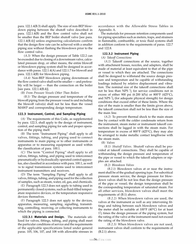
ASME B31.1-2010
para. 122.1.4(B.3) shall apply. The size of non-BEP blow-down piping between the shutoff valve described inpara. 122.1.4(B) and the flow control valve shall notbe smaller than the BEP boiler shutoff valve [see para.122.1.4(B.4)] unless engineering calculations confirmthat the design flow rate can be achieved with a smallerpiping size without flashing the blowdown prior to theflow control valve.
(A.3) When the design pressure of Table 122.2 canbe exceeded due to closing of a downstream valve, calcu-lated pressure drop, or other means, the entire blowoffor blowdown piping system shall be designed in accor-dance with paras. 122.1.4(A) and 122.1.7 for blowoff andpara. 122.1.4(B) for blowdown piping.
(A.4) Non-BEP blowdown piping downstream ofthe flow control valve shall not be smaller — and prefera-bly will be larger — than the connection on the boiler[see para. 122.1.4(B.4)].
(B) From Pressure Vessels Other Than Boilers(B.1) The design pressure and temperature of the
blowoff piping from the pressure vessel to and includingthe blowoff valve(s) shall not be less than the vesselMAWP and corresponding design temperature.
122.3 Instrument, Control, and Sampling Piping
(A) The requirements of this Code, as supplementedby para. 122.3, shall apply to the design of instrument,control, and sampling piping for safe and proper opera-tion of the piping itself.
(B) The term “Instrument Piping” shall apply to allvalves, fittings, tubing, and piping used to connectinstruments to main piping or to other instruments orapparatus or to measuring equipment as used withinthe classification of para. 100.1.
(C) The term “Control Piping” shall apply to allvalves, fittings, tubing, and piping used to interconnectpneumatically or hydraulically operated control appara-tus, also classified in accordance with para. 100.1, as wellas to signal transmission systems used to interconnectinstrument transmitters and receivers.
(D) The term “Sampling Piping” shall apply to allvalves, fittings, tubing, and piping used for the collectionof samples, such as steam, water, oil, gas, and chemicals.
(E) Paragraph 122.3 does not apply to tubing used inpermanently closed systems, such as fluid-filled temper-ature responsive devices, or the temperature responsivedevices themselves.
(F) Paragraph 122.3 does not apply to the devices,apparatus, measuring, sampling, signalling, transmit-ting, controlling, receiving, or collecting instruments towhich the piping is connected.
122.3.1 Materials and Design. The materials uti-lized for valves, fittings, tubing, and piping shall meetthe particular conditions of service and the requirementsof the applicable specifications listed under generalparas. 105, 106, 107, and 108 with allowable stresses in
56
accordance with the Allowable Stress Tables inAppendix A.
The materials for pressure retention components usedfor piping specialties such as meters, traps, and strainersin flammable, combustible, or toxic fluid systems shallin addition conform to the requirements of paras. 122.7and 122.8.
122.3.2 Instrument Piping(A) Takeoff Connections
(A.1) Takeoff connections at the source, togetherwith attachment bosses, nozzles, and adapters, shall bemade of material at least equivalent to that of the pipeor vessel to which they are attached. The connectionsshall be designed to withstand the source design pres-sure and temperature and be capable of withstandingloadings induced by relative displacement and vibra-tion. The nominal size of the takeoff connections shallnot be less than NPS 1⁄2 for service conditions not inexcess of either 900 psi (6 200 kPa) or 800°F (425°C),and NPS 3⁄4 (for adequate physical strength) for designconditions that exceed either of these limits. Where thesize of the main is smaller than the limits given above,the takeoff connection shall not be less than the size ofthe main line.
(A.2) To prevent thermal shock to the main steamline by contact with the colder condensate return fromthe instrument, steam meter or instrument takeoff con-nections shall be lagged in with the steam main. Fortemperature in excess of 800°F (425°C), they may alsobe arranged to make metallic contact lengthwise withthe steam main.
(B) Valves(B.1) Shutoff Valves. Shutoff valves shall be pro-
vided at takeoff connections. They shall be capable ofwithstanding the design pressure and temperature ofthe pipe or vessel to which the takeoff adapters or nip-ples are attached.
(B.2) Blowdown Valves(B.2.1) Blowdown valves at or near the instru-
ment shall be of the gradual opening type. For subcriticalpressure steam service, the design pressure for blow-down valves shall be not less than the design pressureof the pipe or vessel; the design temperature shall bethe corresponding temperature of saturated steam. Forall other services, blowdown valves shall meet therequirements of (B.1) above.
(B.2.2) When blowdown valves are used, thevalves at the instrument as well as any intervening fit-tings and tubing between such blowdown valves andthe meter shall be suitable at 100°F (40°C) for at least11⁄2 times the design pressure of the piping system, butthe rating of the valve at the instrument need not exceedthe rating of the blowdown valve.
(B.2.3) When blowdown valves are not used,instrument valves shall conform to the requirements of(B.2.1) above.
Copyright ASME International Provided by IHS under license with ASME No reproduction or networking permitted without license from IHS
--`,,```````,,```,`,`,,,,`,`,`,`-`-`,,`,,`,`,,`---
标准分享网 www.bzfxw.com 免费下载

ASME B31.1-2010
(C) Reservoirs or Condensers. In dead end steam ser-vice, the condensing reservoirs and connecting nipples,which immediately follow the shutoff valves, shall bemade of material suitable for the saturated steam tem-perature corresponding to the main line design pressure.
(D) Materials for Lines Between Shutoff Valves andInstruments
(D.1) Copper, copper alloys, and other nonferrousmaterials may be used in dead end steam or water ser-vices up to the design pressure and temperature condi-tions used for calculating the wall thickness inaccordance with para. 104 provided that the temperaturewithin the connecting lines for continuous services doesnot exceed 406°F (208°C).
Where water temperature in the reservoir of condens-ers is above 406°F (208°C), a length of uninsulated steeltubing at least 5 ft (1.5 m) long shall immediately followthe condenser ahead of the connecting copper tubing tothe instrument.
(D.2) The minimum size of the tubing or piping isa function of its length, the volume of fluid required toproduce full scale deflections of the instrument, and theservice of the instrument. When required to preventplugging as well as to obtain sufficient mechanicalstrength, the inside diameter of the pipe or tube shouldnot be less than 0.36 in. (9.14 mm), with a wall thicknessof not less than 0.049 in. (1.25 mm). When these require-ments do not apply, smaller sizes with wall thicknessin due proportions may be used. In either case, wallthickness of the pipe or tube shall meet the requirementsof (D.3) below.
(D.3) The piping or tubing shall be designed inaccordance with para. 104 with consideration for waterhammer.
(E) Fittings and Joints(E.1) For dead end steam service and for water
above 150°F (65°C), fittings of the flared, flareless, orsocket welding type, or other suitable type of similardesign shall be used. The fittings shall be suitable forthe header pressure and corresponding saturated steamtemperature or water temperature, whichever applies.For supercritical pressure conditions the fittings shallbe suitable for the design pressure and temperature ofthe main fluid line.
(E.2) For water, oil and similar instrument services,any of the following types may be used, within thepressure–temperature limitations of each:
(E.2.1) For main line hydraulic pressures above500 psi (3 450 kPa) and temperatures up to 150°F (65°C),steel fittings either of the flared, flareless, socket welded,fusion welded, or silver brazed socket type shall be used.
(E.2.2) For main line pressures up to 500 psi(3 450 kPa) and temperatures up to 150°F (65°C), thefittings may be flared or silver brazed socket type,inverted flared or flareless compression type, all of brassor bronze.
57
(E.2.3) For pressures up to 175 psi (1 200 kPa) ortemperatures up to 250°F (120°C), soldered type fittingsmay be used with water-filled or air-filled tubing underadjusted pressure–temperature ratings. These fittingsare not recommended where mechanical vibration,hydraulic shock, or thermal shock are encountered.
122.3.3 Control Piping(A) Takeoff Connections
(A.1) Takeoff connections shall be in accordancewith para. 122.3.2(A.1).
(B) Valves(B.1) Shutoff valves shall be in accordance with
para. 122.3.2(B.1).(C) Materials
(C.1) The same materials may be used for controllines as for instrument lines, except that the minimuminside diameter shall be 0.178 in. (4.52 mm) with a mini-mum wall thickness of 0.028 in. (0.71 mm), providedthat this wall thickness is not less than that required bypara. 122.3.2(D.3). If a control device has a connectionsmaller than 1⁄4 in. (6.0 mm), the size reduction from thecontrol tubing to the control device shall be made asclose to the control device as possible.
(D) Fittings and Joints(D.1) Fittings and joints shall be in accordance with
para. 122.3.2(E.2).
122.3.4 Sampling Piping(A) Takeoff Connections
(A.1) Takeoff connections shall be in accordancewith para. 122.3.2(A.1).
(B) Valves(B.1) Shutoff valves shall be in accordance with
para. 122.3.2(B.1).(B.2) Blowdown valves shall be of the gradual
opening type and shall be suitable for main line designpressure and temperature.
(C) Materials(C.1) The materials to be used for sampling lines
shall conform to minimum requirements for the mainline to which they connect.
(D) Fittings and Joints(D.1) For subcritical and supercritical pressure
steam, and for water above 150°F (65°C), fittings of theflared, flareless, or socket welding type, or other suitabletype of similar design shall be used. The fittings shall besuitable for main line design pressure and temperature.
(D.2) For water below 150°F (65°C), fittings andjoints shall be suitable for main line design pressureand temperature and shall be in accordance with para.122.3.2(E.2).
122.3.6 Fittings and Joints(A) All fittings shall be in accordance with standards
and specifications listed in Table 126.1.(A.1) Socket welded joints shall comply with the
requirements of para. 111.3.
Copyright ASME International Provided by IHS under license with ASME No reproduction or networking permitted without license from IHS
--`,,```````,,```,`,`,,,,`,`,`,`-`-`,,`,,`,`,,`---
ASME B31.1-2010
(A.2) Flared, flareless, and compression type fit-tings and their joints shall comply with the requirementsof para. 115.
(A.3) Silver brazed socket type joints shall complywith the requirements of paras. 117.1 and 117.3.
(A.4) Solder type joints shall comply with therequirements of paras. 117.2 and 117.3.
(A.5) The use of taper threaded joints up to andincluding NPS 1⁄2 is permitted at pressures up to 5,000psi (34 500 kPa) in dead end service from outlet endand downstream of shutoff valve located at instrument,at control apparatus, or at discharge of sample cooler.
122.3.7 Special Safety Provisions(A) Connecting piping subject to clogging from solids
or deposits shall be provided with suitable connectionsfor cleaning.
(B) Connecting piping handling air and gases con-taining moisture or other extraneous materials shall beprovided with suitable drains or settling chambers ortraps.
(C) Connecting piping that may contain liquids shallbe protected from damage due to freezing by heatingor other adequate means.
122.3.8 Supports. Supports shall be furnished asspecified in para. 121 not only for safety but also toprotect the piping against detrimental sagging, externalmechanical injury abuse, and exposure to unusual ser-vice conditions.
122.3.9 Installations(A) Instrument, control, and sampling piping shall
be inspected and tested in accordance with paras. 136and 137.
(B) The inside of all piping, tubing, valves, and fit-tings shall be smooth, clean, and free from blisters, loosemill scale, sand, and dirt when erected. All lines shall becleaned after installation and before placing in service.
122.4 Spray-Type Desuperheater Piping for Use onSteam Generators, Main Steam, and ReheatSteam Piping
(A) Valves and Piping Arrangement(A.1) Each spraywater pipe connected to a desuper-
heater shall be provided with a stop valve and a regulat-ing (spray control) valve. The regulating valve shall beinstalled upstream of the stop valve. In addition, if thesteam generator supplies steam to a steam turbine, apower-operated block valve5 shall be installed upstreamof the regulating valve.
(A.2) A bypass valve around the regulating valveis permitted.
(A.3) A bypass valve around the power-operatedblock valve is prohibited.
5 For information on the prevention of water damage to steamturbines used for electric power generation, see ASME TDP-1.
58
(A.4) On a superheater or reheater desuperheater,a drain valve shall be installed between the power-operated block valve and the regulating valve.
(A.5) If the spraywater supply is from the boilerfeedwater system and its source is not downstream ofthe feedwater check valve required by para. 122.1.7, acheck valve shall be provided in the spraywater pipingbetween the desuperheater and the spraywater source.
(A.6) It is recommended that the valves and pipingbe arranged to provide a head of water on the down-stream side of the stop valve.
(A.7) A typical arrangement is shown in Fig. 122.4.(A.8) Provisions shall be made to both steam and
water systems to accommodate the operating conditionsassociated with this service including: water hammer,thermal shock and direct water impingement. The con-nection for the spraywater pipe should be located perthe requirements established by the manufacturer so thatcomplete flow mixing is achieved prior to any bends,elbows, or other flow directional changes beingencountered.
(A.9) Insertable-type desuperheaters, whichinclude an integral stop and spraywater regulatingvalve, may be used within the limitations establishedby the manufacturer. If this type is used, the individualstop and regulating valves shown in Fig. 122.4 may beomitted. All other requirements described in para. 122.4shall apply.
(A.10) For Desuperheaters Located Within Main Steamor Reheat Steam Piping. The steam system to be desuper-heated shall be provided with proper drainage duringall water flow conditions. The drainage system shallfunction both manually and automatically.
(B) Design Requirements(B.1) The value of P to be used in the formulas of
para. 104 shall be as follows:(B.1.1) For piping from the desuperheater back
to the stop valve required by (A.1) above, the value of Pshall be equal to or greater than the maximum allowableworking pressure of the desuperheater.
(B.1.2) For the remainder of the spraywater pip-ing system, the value of P shall be not less than themaximum sustained pressure exerted by the spraywater.
(B.2) The stop valve required by (A.1) above shallbe designed for the pressure requirement of (B.1.1) aboveor the maximum sustained pressure exerted by thespraywater, whichever is greater.
(B.3) The S value used for the spraywater pipingshall not exceed that permitted for the expectedtemperature.
NOTE: The temperature varies from that of the desuperheaterto that of the spraywater source and is highly dependent on thepiping arrangement. It is the responsibility of the designer to deter-mine the design temperature to be used for the various sectionsof the piping system.
Copyright ASME International Provided by IHS under license with ASME No reproduction or networking permitted without license from IHS
--`,,```````,,```,`,`,,,,`,`,`,`-`-`,,`,,`,`,,`---
标准分享网 www.bzfxw.com 免费下载

ASME B31.1-2010
Fig. 122.4 Desuperheater Schematic Arrangement
Desuperheater
Stop valve
Block valve
Drain valve — required on superheater and reheater desuperheaters
From spray water source
Regulating valve
GENERAL NOTE: This Figure is a schematic only and is not intended to show equipment layout or orientation.
122.5 Pressure-Reducing Valves
122.5.1 General. Where pressure-reducing valvesare used, one or more relief devices or safety valves shallbe provided on the low pressure side of the system.Otherwise, the piping and equipment on the low pres-sure side of the system shall be designed to withstandthe upstream design pressure. The relief or safetydevices shall be located adjoining or as close as practica-ble to the reducing valve. The combined relieving capac-ity provided shall be such that the design pressure ofthe low pressure system will not be exceeded if thereducing valve fails open.
122.5.2 Bypass Valves. Hand controlled bypassvalves having a capacity no greater than the reducingvalve may be installed around pressure reducing valvesif the downstream piping is protected by relief valvesas required in para. 122.5.1 or if the design pressure ofthe downstream piping system and equipment is at leastas high as the upstream pressure.
122.5.3 Design of Valves and Relief Devices. Pres-sure reducing and bypass valves, and relief devices, shallbe designed for inlet pressure and temperature condi-tions. Safety and relief valves shall be in accordancewith the requirements of para. 107.8 of this Code.
122.6 Pressure Relief Piping
Pressure relief piping within the scope of this Codeshall be supported to sustain reaction forces, and shall
59
conform to the requirements of paras. 122.6.1 and122.6.2.
122.6.1 Piping to Pressure-Relieving Safety Devices(A) There shall be no intervening stop valve(s)
between piping being protected and the protectivedevice(s).
(B) Diverter or changeover valves designed to allowservicing of redundant protective devices without sys-tem depressurization may be installed between the pip-ing to be protected and the required protective devicesunder the following conditions:
(B.1) Diverter or changeover valves are prohibitedon boiler external piping or reheat piping.
(B.2) One hundred percent (100%) of the requiredrelieving capacity shall be continuously available anytime the system is in service.
(B.3) Positive position indicators shall be providedon diverter or changeover valves.
(B.4) Positive locking mechanisms and seals shallbe provided on diverter or changeover valves to pre-clude unauthorized or accidental operation.
(B.5) Diverter or changeover valves shall bedesigned for the most severe conditions of pressure,temperature, and loading to which they are exposed,and shall be in accordance with para. 107.
(B.6) Provision shall be made to safely bleed off thepressure between the isolated protective device and thediverter or changeover valve.
Copyright ASME International Provided by IHS under license with ASME No reproduction or networking permitted without license from IHS
--`,,```````,,```,`,`,,,,`,`,`,`-`-`,,`,,`,`,,`---

ASME B31.1-2010
122.6.2 Discharge Piping From Pressure-RelievingSafety Devices
(A) There shall be no intervening stop valve betweenthe protective device or devices and the point ofdischarge.
(B) When discharging directly to the atmosphere, dis-charge shall not impinge on other piping or equipmentand shall be directed away from platforms and otherareas used by personnel.
(C) It is recommended that individual discharge linesbe used, but if two or more reliefs are combined, thedischarge piping shall be designed with sufficient flowarea to prevent blowout of steam or other fluids. Sec-tional areas of a discharge pipe shall not be less thanthe full area of the valve outlets discharging thereintoand the discharge pipe shall be as short and straight aspossible and so arranged as to avoid undue stresses onthe valve or valves.
(D) Discharge lines from pressure-relieving safetydevices within the scope of this Code shall be designedto facilitate drainage.
(E) When the umbrella or drip pan type of connectionis used, the discharge piping shall be so designed as toprevent binding due to expansion movements.
(F) Drainage shall be provided to remove water col-lected above the safety valve seat.
(G) Carbon steel materials listed in Appendix A maybe used for discharge piping that is subjected to temper-atures above 800°F (427°C) only during operation ofpressure relieving safety devices provided that
(G.1) the duration of pressure relieving safetydevice operation is self-limiting
(G.2) the piping discharges directly to atmosphere(G.3) the allowable stresses for carbon steel materi-
als at temperatures above 800°F (427°C) shall be takenfrom Section II, Part D, Table 1A for materials applicableto Section I and Section VIII, Division 1 of the ASMEBoiler and Pressure Vessel Code
122.7 Piping for Flammable or Combustible Liquids
122.7.1 General. Piping for flammable or combusti-ble liquids including fuel and lubricating oils is withinthe scope of this Code. Piping for synthetic lubricantshaving no flash or fire point need not meet the require-ments of para. 122.7.
The designer is cautioned that, among other criteria,static electricity may be generated by the flowing fluid.Additionally, the designer is cautioned of the extremechilling effect of a liquefied gas flashing to vapor duringloss of pressure. This is a factor for determining thelowest expected service temperature relative to the pos-sibility of brittle fracture of materials. Consideration
60
shall also be given to the pressure rise that may occuras a cold fluid absorbs heat from the surroundings.
122.7.2 Materials(A) Seamless steel or nickel alloy piping materials
shall be used in all areas where the line is within 25 ft(7.6 m) of equipment or other lines having an open flameor exposed parts with an operating temperature above400°F (204°C). Seamless steel or nickel alloy pipe shallalso be used for fuel oil systems located downstream ofburner shutoff valve(s). The burner shutoff valve(s) shallbe located as close to the burner as is practical.
(B) In all other areas, piping systems may includepipe or tube of steel, nickel alloy, copper, or brass con-struction. Copper tubing shall have a thickness not lessthan that required by para. 104.1.2(C.3), regardless ofpressure. Refer also to paras. 105, 124.6, and 124.7(A).
Wherever materials other than steel or nickel alloy areused, they shall be so located that any spill resultingfrom the failure of these materials will not unduly exposepersons, buildings, or structures, or can be readily con-trolled by remote valves.
(C) For lubricating oil systems, steel tubing is anacceptable alternative to steel pipe.
(D) Polyethylene (PE) and reinforced thermosettingresin (RTR) pipe may be used for flammable or combusti-ble liquids in buried installations only. The fluid temper-atures shall not exceed 140°F (60°C) and pressures shallbe limited to 150 psi (1 000 kPa). Where such PE or RTRpipe is used in flammable or combustible liquid service,the rules of Appendix III shall be considered mandatory.Where jurisdictional requirements mandate that doublecontainment pipe be used, the rules of Appendix IIIshall be applied to both the inner and outer pipe.
Particular care must be exercised to prevent damageto RTR piping at the connection to the main or otherfacility. Precautions shall be taken to prevent crushingor shearing of RTR piping due to external loading orsettling of backfill and to prevent damage or pull outfrom the terminal connection resulting from thermalexpansion or contraction.
RTR piping may terminate above ground and outsidea building, provided that:
(D.1) the above ground portion of the RTR pipe iscompletely enclosed in a conduit or casing of sufficientstrength to provide protection from external damageand deterioration. Where a flexible conduit is used, thetop of the riser must be attached to a solid support.The conduit or casing shall extend a minimum of 6 in.(150 mm) below grade.
(D.2) the RTR pipe is not subjected to excessivestresses due to external loading.
122.7.3 Piping Joints(A) Welded joints shall be used between steel or nickel
alloy piping components where practicable. Wherebolted flanged joints are necessary, the gasket material
Copyright ASME International Provided by IHS under license with ASME No reproduction or networking permitted without license from IHS
--`,,```````,,```,`,`,,,,`,`,`,`-`-`,,`,,`,`,,`---
标准分享网 www.bzfxw.com 免费下载

ASME B31.1-2010
shall be suitable for the service. Where threaded jointsand compression fittings are unavoidable, the followingrequirements shall be met:
(A.1) For threaded joints, the pipe thickness shallbe not less than Extra Strong regardless of pressure ortype of material.
(A.2) The requirements of para. 114 shall apply toall threaded joints.
(A.3) Threaded joints and compression fittingsshall be assembled carefully to ensure leak tightness.Threaded joints shall meet the requirements of para.135.5. Compression fittings shall meet the requirementsof paras. 115 and 135.6. A thread sealant, suitable forthe service, shall be used in threaded joints unless thejoint is to be seal welded or a gasket or O-ring is usedto provide sealing at a surface other than the threads.
(B) Threaded joints in copper or brass pipe shall besubject to the same limitations as for steel pipe in (A.1),(A.2), and (A.3), above.
(C) Copper tubing shall be assembled with flared,flareless, or compression type joints as prescribed inpara. 115, or brazed in accordance with para. 117. Softsolder type joints are prohibited.
(D) RTR pipe shall be adhesive bonded in accordancewith the pipe manufacturer’s recommended procedures.
(E) Pipe joints dependent on the friction characteris-tics or resiliency of combustible materials for mechanicalor leak tightness of piping shall not be used insidebuildings.
(F) Steel tubing shall be assembled with fittings inaccordance with para. 115, or with socket weld fittings.
122.7.4 Valves and Specialties. Valves, strainers,meters, and other specialties shall be of steel or nickelalloy construction. As an alternative, ductile or mallea-ble iron or copper alloy valves and specialties may beused, subject to the restrictions in paras. 124.6 and 124.7,where metal temperatures do not exceed 400°F (204°C).
122.8 Piping for Flammable Gases, Toxic Fluids(Gases or Liquids), or Nonflammable NontoxicGases
(A) Although some gases are liquefied for storage ortransport, they shall be considered as gases if their Reidvapor pressure is greater than 40 psia [2 068.6 mm Hg(absolute)] at 100°F (37.8°C).
(B) Threaded joints and compression fittings may beused subject to the limitations of para. 114.2.1(B) andother specific limitations identified below, except theyare permitted at connections to refillable storage contain-ers and associated pressure regulators, shutoff valves,pumps, and meters, to a maximum pressure of 5,000 psig[34 475 kPa (gage)], provided the size does not exceedNPS 3⁄4 (DN 20).
122.8.1 Flammable Gas(A) Some of the common flammable gases are acety-
lene, ethane, ethylene, hydrogen, methane, propane,
61
butane, and natural or manufactured gas used for fuel.It shall be the designers’ responsibility to determinethe limiting concentrations (upper and lower explosivelimits) and the properties of the gas under consideration.The use of explosive concentrations shall be avoided,or the piping shall be designed to withstand explosiveforces.
The designer is further cautioned of the extreme chill-ing effect of gas during rapid expansion. This is a factorfor determining the lowest expected service temperaturerelative to the possibility of brittle fracture of materials.
(B) Materials. Steel piping, subject to the limitationsin para. 105, shall be used for all flammable gases, exceptas otherwise permitted in (B.2), (B.3), and (B.4) below.
(B.1) Welded joints shall be used between steelcomponents where practicable. Where bolted flangedjoints are necessary, the gasket material shall be suitablefor the service. Where threaded joints and compressionfittings are unavoidable, the following requirementsshall be met:
(B.1.1) For threaded joints, the pipe thicknessshall be not less than Extra Strong regardless of pressureor type of material.
(B.1.2) Threaded joints and compression fittingsmay be used subject to the limitations of para. 122.8(B).
(B.1.3) Threaded joints and compression fittingsshall be assembled carefully to ensure leak tightness.Threaded joints shall meet the requirements of para.135.5. Compression fittings shall meet the requirementsof paras. 115 and 135.6. A thread sealant, suitable forthe service, shall be used in threaded joints unless thejoint is to be seal welded or a gasket or O-ring is usedto provide sealing at a surface other than the threads.
(B.2) For hydrogen systems, the following alterna-tive materials may be used:
(B.2.1) seamless steel tubing with welded joints;(B.2.2) seamless copper or brass pipe or tubing
with brazed, threaded, or compression fitting joints.Threaded fittings shall not exceed NPS 3⁄4 (DN 20). Forprotection against damage, tubing shall be installed ina guarded manner that will prevent damage during con-struction, operation, or service. Valves with suitablepacking, gages, regulators, and other equipment mayalso consist of copper alloy materials. Safety reliefdevices shall be vented individually, and connected ventpiping shall be designed to convey the fluid, withoutpockets, to the outside atmosphere; and then directedaway from equipment ventilation systems, and ventsfrom other systems.
(B.3) For fuel gas instrumentation and control,seamless copper tubing subject to the following restric-tions may be used:
(B.3.1) The design pressure shall not exceed100 psi (690 kPa).
(B.3.2) Tubing shall not exceed 5⁄8 in. (15.9 mm)nominal outside diameter.
Copyright ASME International Provided by IHS under license with ASME No reproduction or networking permitted without license from IHS
--`,,```````,,```,`,`,,,,`,`,`,`-`-`,,`,,`,`,,`---
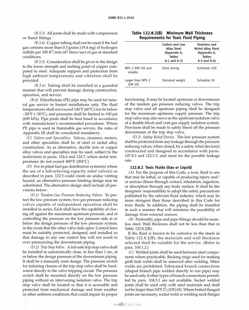
ASME B31.1-2010
(B.3.3) All joints shall be made with compressionor flared fittings.
(B.3.4) Copper tubing shall not be used if the fuelgas contains more than 0.3 grains (19.4 mg) of hydrogensulfide per 100 ft3/min (47 liters/sec) of gas at standardconditions.
(B.3.5) Consideration shall be given in the designto the lower strength and melting point of copper com-pared to steel. Adequate support and protection fromhigh ambient temperatures and vibration shall beprovided.
(B.3.6) Tubing shall be installed in a guardedmanner that will prevent damage during construction,operation, and service.
(B.4) Polyethylene (PE) pipe may be used for natu-ral gas service in buried installations only. The fluidtemperatures shall not exceed 140°F (60°C) nor be below−20°F (−30°C), and pressures shall be limited to 100 psi(690 kPa). Pipe joints shall be heat fused in accordancewith manufacturer’s recommended procedures. WherePE pipe is used in flammable gas service, the rules ofAppendix III shall be considered mandatory.
(C) Valves and Specialties. Valves, strainers, meters,and other specialties shall be of steel or nickel alloyconstruction. As as alternative, ductile iron or copperalloy valves and specialties may be used, subject to therestrictions in paras. 124.6 and 124.7, where metal tem-peratures do not exceed 400°F (204°C).
(D) For in-plant fuel gas distribution system(s) wherethe use of a full-relieving-capacity relief valve(s) asdescribed in para. 122.5 could create an undue ventinghazard, an alternative pressure limiting design may besubstituted. The alternative design shall include all pro-visions below:
(D.1) Tandem Gas Pressure Reducing Valves. To pro-tect the low pressure system, two gas pressure reducingvalves capable of independent operation shall beinstalled in series. Each shall have the capability of clos-ing off against the maximum upstream pressure, and ofcontrolling the pressure on the low pressure side at orbelow the design pressure of the low pressure system,in the event that the other valve fails open. Control linesmust be suitably protected, designed, and installed sothat damage to any one control line will not result inover pressurizing the downstream piping.
(D.2) Trip Stop Valve. A fail-safe trip stop valve shallbe installed to automatically close, in less than 1 sec, ator below the design pressure of the downstream piping.It shall be a manually reset design. The pressure switchfor initiating closure of the trip stop valve shall be hard-wired directly to the valve tripping circuit. The pressureswitch shall be mounted directly on the low pressurepiping without an intervening isolation valve. The tripstop valve shall be located so that it is accessible andprotected from mechanical damage and from weatheror other ambient conditions that could impair its proper
62
Table 122.8.2(B) Minimum Wall ThicknessRequirements for Toxic Fluid Piping
Carbon and Low Stainless andAlloy Steel Nickel Alloy Steel
(Appendix A, (Appendix A,Tables Tables
A-1 and A-2) A-3 and A-4)
NPS 2 (DN 50) and Extra strong Schedule 10Ssmaller
Larger than NPS 2 Standard weight Schedule 5S(DN 50)
functioning. It may be located upstream or downstreamof the tandem gas pressure reducing valves. The tripstop valve and all upstream piping shall be designedfor the maximum upstream supply pressure. The tripstop valve may also serve as the upstream isolation valveof a double-block and vent gas supply isolation system.Provision shall be made to safely bleed off the pressuredownstream of the trip stop valve.
(D.3) Safety Relief Device. The low pressure systemshall be protected from any leakage through the pressurereducing valves, when closed, by a safety relief device(s)constructed and designed in accordance with paras.107.8.3 and 122.5.3, and sized for the possible leakagerate.
122.8.2 Toxic Fluids (Gas or Liquid)(A) For the purpose of this Code, a toxic fluid is one
that may be lethal, or capable of producing injury and/or serious illness through contact, inhalation, ingestion,or absorption through any body surface. It shall be thedesigners’ responsibility to adopt the safety precautionspublished by the relevant fluid industry which may bemore stringent than those described in this Code fortoxic fluids. In addition, the piping shall be installedin such a manner that will minimize the possibility ofdamage from external sources.
(B) Preferably, pipe and pipe fittings should be seam-less steel. Wall thickness shall not be less than that inTable 122.8.2(B).
If the fluid is known to be corrosive to the steels inTable 122.8.2(B), the materials and wall thicknessselected shall be suitable for the service. (Refer topara. 104.1.2.)
(C) Welded joints shall be used between steel compo-nents where practicable. Backing rings used for makinggirth butt welds shall be removed after welding. Miterwelds are prohibited. Fabricated branch connections(shaped branch pipe welded directly to run pipe) maybe used only if other types of branch connections permit-ted by para. 104.3.1 are not available. Socket weldedjoints shall be used only with steel materials and shallnot be larger than NPS 21⁄2 (DN 65). Where bolted flangedjoints are necessary, socket weld or welding neck flanges
Copyright ASME International Provided by IHS under license with ASME No reproduction or networking permitted without license from IHS
--`,,```````,,```,`,`,,,,`,`,`,`-`-`,,`,,`,`,,`---
标准分享网 www.bzfxw.com 免费下载

ASME B31.1-2010
shall be used. Gasket materials shall be suitable for theservice. Compression fittings are prohibited. Where theuse of threaded joints is unavoidable, all of the followingrequirements shall be met:
(C.1) The pipe thickness shall be not less than ExtraStrong, regardless of pressure or type of material.
(C.2) In addition to the provisions of para. 122.8(B),threaded joints and compression fittings may be usedat connections to refillable storage containers and associ-ated pressure regulators, shutoff valves, pumps, andmeters to a maximum pressure of 50 psig [345 kPa(gage)], provided the size does not exceed NPS 2(DN 50).
(C.3) Threaded joints shall be assembled carefullyto ensure leak tightness. The requirements of para. 135.5shall be met. A thread sealant, suitable for the service,shall be used unless the joint is to be seal welded or agasket or O-ring is used to provide sealing at a surfaceother than the threads.
(D) Steel valves shall be used. Bonnet joints withtapered threads are not permitted. Special considerationshall be given to valve design to prevent stem leakageto the environment. Bonnet or cover plate closures andother body joints shall be one of the following types:
(D.1) union(D.2) flanged with suitable gasketing and secured
by at least four bolts(D.3) proprietary, attached by bolts, lugs, or other
substantial means, and having a design that increasesgasket compression as fluid pressure increases
(D.4) threaded with straight threads sufficient formechanical strength, metal-to-metal seats, and a sealweld made in accordance with para. 127.4.5, all actingin series
(E) Tubing not larger than 5⁄8 in. (16 mm) O.D. withsocket welding fittings may be used to connect instru-ments to the process line. An accessible root valve shallbe provided at the process lines to permit isolating thetubing from the process piping. The layout and mount-ing of tubing shall minimize vibration and exposure topossible damage.
(F) The provisions of para. 102.2.4 are not permitted.The simplified rules for analysis in para. 119.7.1 (A.3)are not permitted. The piping system shall be designedto minimize impact and shock loads. Suitable dynamicanalysis shall be made where necessary to avoid or mini-mize vibration, pulsation, or resonance effects in thepiping. The designer is cautioned to consider the possi-bility of brittle fracture of the steel material selected overthe entire range of temperatures to which it may besubjected.
(G) For dry chlorine service between −29°C (−20°F)and 149°C (300°F), the pipe material shall not be less inthickness than seamless Extra Strong steel.
(H) Toxic fluid piping shall be pneumatic leak testedin accordance with para. 137.5. Alternatively, mass spec-trometer or halide leak testing in accordance with
63
para. 137.6, and a hydrostatic test in accordance withpara. 137.3 may be performed.
122.8.3 Nonflammable Nontoxic Gas(A) Piping for nonflammable and nontoxic gases,
such as air, oxygen, carbon dioxide, and nitrogen, shallcomply with the requirements of this Code, except asotherwise permitted in (B) (below). The designer is cau-tioned of the extreme chilling effect during rapid expan-sion. This is a factor for determining the lowest expectedservice temperature relative to the brittle fracture of thematerial selected.
(B) Threaded joints and compression fittings may beused subject to the conditions of para. 122.8(B).
122.9 Piping for Corrosive Liquids and Gases
Where it is necessary to use special material, such asglass, plastics, or metallic piping lined with nonmetals,not listed in Table 126.1, for conveying corrosive or haz-ardous liquids and gases, the design shall meet therequirements of para. 104.7.
122.10 Temporary Piping Systems
Prior to test and operation of the power plant andits included piping systems, most power and auxiliaryservice piping are subjected to flushing or chemicalcleaning to remove internal foreign material such as rustparticles, scale, welding or brazing residue, dirt, etc.,which may have accumulated within the piping duringthe construction period. The flushing or cleaning opera-tion may be accomplished by blowing out with steamor air, by hot oil circulation of oil systems, by acid orcaustic fluid circulation, or by other flushing or cleaningmethods. Temporary piping, that is piping attached tothe permanent piping system whose function is to pro-vide means for introducing and removing the fluids usedin the flushing or cleaning operations, shall be designedand constructed to withstand the operating conditionsduring flushing and cleaning. The following minimumrequirements shall apply to temporary piping systems:
(A) Each such system shall be analyzed for compli-ance with para. 103.
(B) Connections for temporary piping to the perma-nent piping systems that are intended to remain, shallmeet the design and construction requirements of thepermanent system to which they are attached.
(C) The temporary systems shall be supported suchthat forces and moments due to static, dynamic andexpansion loadings will not be transferred in an unac-ceptable manner to the connected permanent pipingsystem. Paragraphs 120 and 121 shall be used as guid-ance for the design of the temporary piping systemssupporting elements.
(D) The temporary systems shall be capable of with-standing the cyclic loadings that occur during the flush-ing and cleaning operations. Particular attention shallbe given to the effects of large thrust forces that may be
Copyright ASME International Provided by IHS under license with ASME No reproduction or networking permitted without license from IHS
--`,,```````,,```,`,`,,,,`,`,`,`-`-`,,`,,`,`,,`---
ASME B31.1-2010
generated during high velocity blowing cycles. Wheresteam piping is to be subjected to high velocity blowingoperations, continuous or automatic draining of trappedor potentially trapped water within the system shallbe incorporated. Supports at the exhaust terminals ofblowdown piping shall provide for restraint of potentialpipe whip.
(E) Where necessary, temporary systems containingcast iron or carbon steel material subject to chemicalcleaning shall be prewarmed to avoid the potential forbrittle failure of the material.
(F) Where temporary piping has been installed andit does not comply with the requirements of this Codefor permanent piping systems, it shall be physicallyremoved or separated from the permanent piping towhich it is attached prior to testing of the permanentpiping system and prior to plant startup.
122.11 Steam Trap Piping
122.11.1 Drip Lines. Drip lines from piping orequipment operating at different pressures shall not beconnected to discharge through the same trap.
122.11.2 Discharge Piping. Trap discharge pipingshall be designed to the same pressure as the inlet pipingunless the discharge is vented to atmosphere, or is oper-ated under low pressure and has no stop valves. In nocase shall the design pressure of trap discharge pipingbe less than the maximum discharge pressure to whichit may be subjected. Where two or more traps dischargeinto the same header, a stop valve shall be provided inthe discharge line from each trap. Where the pressurein the discharge piping can exceed the pressure in theinlet piping, a check valve shall be provided in the trapdischarge line. A check valve is not required if either thestop valve or the steam trap is designed to automaticallyprevent reverse flow and is capable of withstanding areverse differential pressure equal to the design pressureof the discharge piping.
122.12 Exhaust and Pump Suction Piping
Exhaust and pump suction lines for any service andpressure shall have relief valves of suitable size unlessthe lines and attached equipment are designed for themaximum pressure to which they may accidentally orotherwise be subjected, or unless a suitable alarm indica-tor, such as a whistle or free blowing relief valve, isinstalled where it will warn the operator.
122.13 Pump Discharge Piping
Pump discharge piping from the pump up to andincluding the valve normally used for isolation or flowcontrol shall be designed for the maximum sustained
64
pressure exerted by the pump and for the highest coinci-dent fluid temperature, as a minimum. Variations inpressure and temperature due to occasional inadvertentoperation are permitted as limited in para. 102.2.4 underany of the following conditions:
(A) during operation of overpressure relief devicesdesigned to protect the piping system and the attachedequipment
(B) during a short period of abnormal operation, suchas pump overspeed
(C) during uncontrolled transients of pressure ortemperature
122.14 District Heating and Steam DistributionSystems
122.14.1 General. Where pressure reducing valvesare used, one or more relief devices or safety valves shallbe provided on the low pressure side of the system.Otherwise, the piping and equipment on the low pres-sure side of the system shall be designed to withstandthe upstream design pressure. The relief or safetydevices shall be located adjoining or as close as practica-ble to the reducing valve. The combined relieving capac-ity provided shall be such that the design pressure ofthe low pressure system will not be exceeded if thereducing valve fails open.
122.14.2 Alternative Systems. In district heatingand steam distribution systems where the steam pres-sure does not exceed 400 psi (2 750 kPa) and where theuse of relief valves as described in para. 122.14.1 is notfeasible (e.g., because there is no acceptable dischargelocation for the vent piping), alternative designs maybe substituted for the relief devices. In either case, it isrecommended that alarms be provided that will reliablywarn the operator of failure of any pressure reducingvalve.
(A) Tandem Steam Pressure Reducing Valves. Two ormore steam pressure reducing valves capable of inde-pendent operation may be installed in series, each setat or below the safe working pressure of the equipmentand piping system served. In this case, no relief deviceis required.
Each pressure reducing valve shall have the capabilityof closing off against full line pressure, and of controllingthe reduced pressure at or below the design pressure ofthe low pressure system, in the event that the other valvefails open.
(B) Trip Stop Valves. A trip stop steam valve set toclose at or below the design pressure of the low pressuresystem may be used in place of a second reducing valveor a relief valve.
Copyright ASME International Provided by IHS under license with ASME No reproduction or networking permitted without license from IHS
--`,,```````,,```,`,`,,,,`,`,`,`-`-`,,`,,`,`,,`---标准分享网 www.bzfxw.com 免费下载

ASME B31.1-2010
Chapter IIIMaterials
123 GENERAL REQUIREMENTS
Chapter III contains limitations and required qualifica-tions for materials based on their inherent properties.Use of these materials in piping systems is also subjectto requirements and limitations in other parts of thisCode.
123.1 Materials and Specifications
123.1.1 Listed Materials. Material meeting the fol-lowing requirements shall be considered listed andacceptable material:
(A) Materials for which allowable stress values arelisted in Appendix A or that have been approved by theprocedure established by (C) below.
(B) A material conforming to a specification for whichallowable stresses are not listed in Appendix A is accept-able provided its use is not specifically prohibited bythis Code Section and it satisfies one of the followingrequirements:
(B.1) It is referenced in a standard listed inTable 126.1. Such a material shall be used only withinthe scope of and in the product form covered by thereferencing standard listed in Table 126.1.
(B.2) It is referenced in other parts of this CodeSection and shall be used only within the scope of andin the product form permitted by the referencing text.
(C) Where it is desired to use materials that are notcurrently acceptable under the rules of this Code Section,written application shall be made to the Committee fullydescribing the proposed material and the contemplateduse. Such material shall not be considered listed andnot used as a listed material until it has been approvedby the Committee and allowable stress values have beenassigned. Details of information that should be includedin such applications are given in Appendix VI. Seepara. 123.1.2.
(D) Materials conforming to ASME SA or SB specifi-cations may be used interchangeably with material spec-ified to the listed ASTM A or B specifications of the samenumber, except where the requirements of para. 123.2.2apply.
(E) The tabulated stress values in Appendix A thatare shown in italics are at temperatures in the rangewhere creep and stress rupture strength govern the selec-tion of stresses.
123.1.2 Unlisted Materials. Materials other thanthose meeting the requirements of para. 123.1.1 shall be
65
considered unlisted materials. Such unlisted materialsmay only be used for nonboiler external piping providedthey satisfy all of the following requirements:
(A) Unlisted materials are certified by the materialmanufacturer to satisfy the requirements of a specifica-tion listed in any Code Section of the ASME B31 Codefor Pressure Piping, the ASME Boiler and Pressure VesselCode, Section II, Part D, or to a published specificationcovering chemistry, physical and mechanical properties,method and process of manufacture, heat treatment, andquality control.
(B) The allowable stresses of the unlisted materialsshall be determined in accordance with the rules ofpara. 102.3.1(C).
(C) Unlisted materials shall be qualified for servicewithin a stated range of minimum and maximum tem-peratures based upon data associated with successfulexperience, tests, or analysis; or a combination thereof.
(D) The designer shall document the owner’s accept-ance for use of unlisted material.
(E) All other requirements of this Code are satisfied.
123.1.3 Unknown Materials. Materials of unknownspecification shall not be used for pressure containingpiping components.
123.1.5 Size or Thickness. Materials outside thelimits of size or thickness given in the title or scopeclause of any specification listed in Table 126.1 may beused if the material is in compliance with the otherrequirements of the specification, and no other similarlimitation is given in the rules for construction.
123.1.6 Marking of Materials or Products. Materialsor products marked as meeting the requirements formore than one grade, type, or alloy of a material specifi-cation or multiple specifications, are acceptableprovided
(A) one of the markings includes the material specifi-cation, grade, class, and type or alloy of the materialpermitted by this Code and the material meets all therequirements of that specification
(B) the appropriate allowable stress for the specifiedgrade, type, or alloy of a material specification fromAppendix A is used
(C) all other requirements of this Code are satisfiedfor the material permitted
Copyright ASME International Provided by IHS under license with ASME No reproduction or networking permitted without license from IHS
--`,,```````,,```,`,`,,,,`,`,`,`-`-`,,`,,`,`,,`---
ASME B31.1-2010
123.1.7 Materials Manufactured to OtherSpecification Editions. Materials may meet the require-ments of material specification editions other than theeditions listed in Appendix F provided
(A) the materials are the same specification, grade,type, class, or alloy, and heat-treated condition, asapplicable.
(B) the material tensile and yield strengths shall becompared and any differences shall be evaluated. If thematerial has a lower strength than required by the edi-tion of the specification in Appendix F, the effect of thereduction on the allowable stress and the design shallbe reconciled.
123.2 Piping Components
123.2.1 General. Materials that do not comply withthe rules of para. 123.1 may be used for flared, flareless,and compression type tubing fittings, provided that therequirements of para. 115 are met.
123.2.2 Boiler External Piping(A) Materials for boiler external piping, as defined in
para. 100.1.2(A), shall be specified in accordance withASME SA, SB, or SFA specifications. Material producedunder an ASTM specification may be used, providedthat the requirements of the ASTM specification areidentical or more stringent than the ASME specificationfor the Grade, Class, or Type produced. The materialmanufacturer or component manufacturer shall certify,with evidence acceptable to the Authorized Inspector,that the ASME specification requirements have beenmet. Materials produced to ASME or ASTM materialspecifications are not limited as to country of origin.
(B) Materials that are not fully identified shall complywith PG-10 of Section I of the ASME Boiler and PressureVessel Code.
(C) In addition to materials listed in Appendix Awithout Note (1), materials that are listed in Section Iof the ASME Boiler and Pressure Vessel Code may beused in boiler external piping. When such Section I mate-rials are used, the allowable stresses shall be those listedin Section II, Part D, Subpart 1, Tables 1A and 1B applica-ble to Section I. For these Section I materials, the applica-ble requirements in Table 1A, Table 1B, and Section Iparas. PG-5 through PG-13, PW-5, PWT-5, PMB-5, andPEB-5 shall me met.
123.3 Pipe-Supporting Elements
Materials used for pipe-supporting elements shall besuitable for the service and shall comply with therequirements of para. 121.2(C), para. 121.7.2(C), para.121.7.2(D), para. 123.1, or MSS SP-58. When utilizingMSS SP-58, the allowable stresses for unlisted materialsshall be established in accordance with the rules of para.102.3.1(C) of ASME B31.1 in lieu of para. 4.4 ofMSS SP-58.
66
123.4 Longitudinal-Welded or Spiral-Welded PipeWith Filler Metal Added
(A) For the purposes of para. 104.1.1, the start of thecreep range is the highest temperature where the non-italicized stress values end in Appendix A.
(B) All welds in longitudinal-welded or spiral-weldedpipe operating in the creep range shall receive and passa 100% volumetric examination (RT or UT) per the appli-cable material specification or in accordance with para.136.4.5 or 136.4.6 and Table 136.4, or the joint efficiencyfactor (used as a multiplier to the weld strength reduc-tion factor) from Table 102.4.7 shall be used.
124 LIMITATIONS ON MATERIALS
124.1 Temperature Limitations
124.1.1 Upper Temperature Limits. The materialslisted in the Allowable Stress Tables A-1 through A-10,Appendix A, shall not be used at design temperaturesabove those for which stress values are given except aspermitted by para. 122.6.2(G).
124.1.2 Lower Temperature Limits. The designershall give consideration to the possibility of brittle frac-ture at low service temperature.
124.2 Steel
(A) Upon prolonged exposure to temperatures above800°F (427°C), the carbide phase of plain carbon steel,plain nickel alloy steel, carbon–manganese alloy steel,manganese–vanadium alloy steel, and carbon–siliconsteel may be converted to graphite.
(B) Upon prolonged exposure to temperatures above875°F (470°C), the carbide phase of alloy steels, such ascarbon–molybdenum, manganese–molybdenum–vanadium, manganese–chromium–vanadium, andchromium–vanadium, may be converted to graphite.
(C) Carbon or alloy steel having carbon content ofmore than 0.35% shall not be used in welded construc-tion or be shaped by oxygen cutting process or otherthermal cutting processes.
(D) Where low alloy 2¼% chromium steels are usedat temperatures above 850°F (455°C), the carbon contentof the base material and weld filler metal shall be 0.05%or higher.
124.4 Cast Gray Iron
The low ductility of cast gray iron may result in suddenfailure if shock loading (pressure, temperature, ormechanical) should occur. Possible shock loadings andconsequences of failure must be considered before speci-fying the use of such material. Cast iron componentsmay be used within the nonshock pressure–temperatureratings established by the standards and specificationsherein and in para. 105.2.1(B). Castings to ASME SA-278
Copyright ASME International Provided by IHS under license with ASME No reproduction or networking permitted without license from IHS
--`,,```````,,```,`,`,,,,`,`,`,`-`-`,,`,,`,`,,`---标准分享网 www.bzfxw.com 免费下载
ASME B31.1-2010
and ASTM A 278 shall have maximum limits of 250 psig[1 725 kPa (gage)] and 450°F (230°C).
The following referenced paragraphs prohibit orrestrict the use of gray cast iron for certain applicationsor to certain pressure–temperature ratings:
Pipe supports 121.7.2(C)BEP blowoff 122.1.4(A.3)BEP blowdown 122.1.4(B.3)BEP valves and fittings 122.1.7Blowoff valves 122.1.7(C.5) and (C.6)Non-BEP blowoff 122.2(A.1)Non-BEP blowdown 122.2(A.2)Flammable or combustible liquids 122.7.2(A) and (B),
122.7.4Flammable gases 122.8.1(B) and (C)Toxic gases or liquids 122.8.2(B) and (D)
124.5 Malleable Iron
Certain types of malleable iron have low ductility char-acteristics and may be subject to brittle fracture. Mallea-ble iron may be used for design conditions not to exceed350 psig [2 415 kPa (gage)] or 450°F (230°C).
The following referenced paragraphs prohibit orrestrict the use of malleable iron for certain applicationsor to certain pressure–temperature ratings:
Pipe supports 121.7.2(D)BEP blowoff 122.1.4(A.3)BEP blowdown 122.1.4(B.3)Non-BEP blowoff 122.2(A.1)Non-BEP blowdown 122.2(A.2)Flammable or combustible liquids 122.7.2(A) and (B),
122.7.4Flammable gases 122.8.1(B) and (C)Toxic gases or liquids 122.8.2(B) and (D)
124.6 Ductile (Nodular) Iron
Ductile iron components complying with ANSI/AWWA C110/A21.10, C115/A21.15, C151/A21.51, orC153/A21.53 may be used for water and other nontoxic,nonflammable service, with pressure limits as specifiedin those standards and temperature limits as specifiedin para. 106(E). These components may not be used forboiler external piping.
Ductile (nodular) iron components conforming toASME B16.42 may be used for services including boilerexternal piping under the following conditions:
(A) Components for boiler external piping shall beused only within the following limitations.
(A.1) Only ASME SA-395 material may be used.(A.2) Design pressure shall not exceed 350 psig
[2 415 kPa (gage)].(A.3) Design temperature shall not exceed 450°F
(230°C).(B) Welding shall not be used, either in fabrication of
the components or in their assembly as a part of a pipingsystem.
67
(C) The following referenced paragraphs prohibit orrestrict the use of ductile iron for certain applicationsor to certain pressure–temperature ratings:
BEP blowoff 122.1.4(A.3)BEP blowdown 122.1.4(B.3)BEP blowoff valves 122.1.7(C.5) and (C.6)Non-BEP blowoff 122.2(A.1)Non-BEP blowdown 122.2(A.2)Flammable or combustible liquids 122.7.2(A) and (B),
122.7.4Flammable gases 122.8.1(B) and (C)Toxic gases or liquids 122.8.2(B) and (D)Pipe supports 123.3
124.7 Nonferrous Metals
Nonferrous metals may be used in piping systemsunder the following conditions:
(A) The melting points of copper, copper alloys, alu-minum, and aluminum alloys must be considered partic-ularly where there is a fire hazard.
(B) The Designer shall consider the possibility of gal-vanic corrosion when combinations of dissimilar metals,such as copper, aluminum, and their alloys, are used inconjunction with each other or with steel or other metalsin the presence of an electrolyte.
(C) Threaded Connections. A suitable thread com-pound shall be used in making up threaded joints inaluminum pipe to prevent seizing that might cause leak-age and perhaps prevent disassembly. Pipe in theannealed temper should not be threaded.
124.8 Cladding and Lining Materials
Materials with cladding or lining may be used pro-vided that
(a) the base material is an approved Code material.The allowable stress used shall be that of the base metalat the design temperature.
(b) the cladding or lining is a material that in thejudgment of the user is suitable for the intended service,and the cladding/lining and its method of applicationdo not detract from the serviceability of the basematerial.
(c) bending procedures are such that damaging ordetrimental thinning of the cladding material isprevented.
(d) welding and the inspection of welds is in accor-dance with the provisions of Chapters V and VI of thisCode.
(e) the thickness of the cladding is not credited forstructural strength in the piping design.
124.9 Nonmetallic Pipe
This Code recognizes the existence of a wide varietyof nonmetallic piping materials that may be used oncorrosive (either internal or external) or other specializedapplications. Extreme care must be taken in their selec-tion as their design properties vary greatly and depend
Copyright ASME International Provided by IHS under license with ASME No reproduction or networking permitted without license from IHS
--`,,```````,,```,`,`,,,,`,`,`,`-`-`,,`,,`,`,,`---
ASME B31.1-2010
upon the material, type and grade. Particular consider-ation shall be given to the possibility of
(A) destruction where fire hazard is involved.(B) decrease in tensile strength at slight increase in
temperature.(C) effects of toxicity. Another consideration is that
of providing adequate support for the flexible pipe.For nonmandatory rules for nonmetallic piping, see
Appendix III of this Code.
124.10 Deterioration of Materials in Service
It is the responsibility of the engineer to select materi-als suitable for the intended application. Some guideline
68
for selection of protective coatings for metallic pipingare provided in Appendix IV.
125 MATERIALS APPLIED TO MISCELLANEOUSPARTS
125.1 Gaskets
Limitations on gasket materials are covered in para.108.4.
125.2 Bolting
Limitations on bolting materials are covered inpara. 108.5.
Copyright ASME International Provided by IHS under license with ASME No reproduction or networking permitted without license from IHS
--`,,```````,,```,`,`,,,,`,`,`,`-`-`,,`,,`,`,,`---
标准分享网 www.bzfxw.com 免费下载

ASME B31.1-2010
Chapter IVDimensional Requirements
126 MATERIAL SPECIFICATIONS AND STANDARDSFOR STANDARD AND NONSTANDARD PIPINGCOMPONENTS
126.1 Standard Piping Components
Dimensions of standard piping components shall com-ply with the standards and specifications listed inTable 126.1 in accordance with para. 100.
126.2 Nonstandard Piping Components
When nonstandard piping components are designedin accordance with para. 104, adherence to dimensionalstandards of ANSI and ASME is strongly recommendedwhen practicable.
69
126.3 Referenced DocumentsThe documents listed in Table 126.1 may contain refer-
ences to codes, standards, or specifications not listed inthis Table. Such unlisted codes, standards, or specifica-tions are to be used only in the context of the listeddocuments in which they appear.
Where documents listed in Table 126.1 contain designrules that are in conflict with this Code, the design rulesof this Code shall govern.
The fabrication, assembly, examination, inspection,and testing requirements of Chapters V and VI applyto the construction of piping systems. These require-ments are not applicable to piping components manufac-tured in accordance with the documents listed inTable 126.1 unless specifically so stated.
Copyright ASME International Provided by IHS under license with ASME No reproduction or networking permitted without license from IHS
--`,,```````,,```,`,`,,,,`,`,`,`-`-`,,`,,`,`,,`---

ASME B31.1-2010
Table 126.1 Specifications and Standards
AISC Publication
(10)
. . . Manual of Steel Construction Allowable Stress Design
ASCE Standard
ASCE/SEI 7 Minimum Design Loads for Buildings and Other Structures
ASTM Ferrous Material Specifications
Bolts, Nuts, and Studs
A 193/A 193M Alloy-Steel and Stainless Steel Bolting Materials for High-Temperature ServiceA 194/A 194M Carbon and Alloy Steel Nuts for Bolts for High-Pressure and High-Temperature ServiceA 307 Carbon Steel Bolts and Studs, 60,000 psi Tensile StrengthA 320/A 320M Alloy-Steel Bolting Materials for Low-Temperature ServiceA 354 Quenched and Tempered Alloy Steel Bolts, Studs and Other Externally-Threaded FastenersA 437/A 437M Alloy-Steel Turbine-Type Bolting Material Specially Heat Treated for High Temperature ServiceA 449 Quenched and Tempered Steel Bolts and StudsA 453 / A 453M High-Temperature Bolting Materials, With Expansion Coefficients Comparable to Austenitic Steels
Castings
A 47/A 47M Ferritic Malleable Iron CastingsA 48/A 48M Gray Iron CastingsA 126 Gray Iron Castings for Valves, Flanges, and Pipe FittingsA 197/A 197M Cupola Malleable IronA 216/A 216M Steel Castings, Carbon Suitable for Fusion Welding for High Temperature ServiceA 217/A 217M Steel Castings, Martensitic Stainless and Alloy, for Pressure-Containing Parts Suitable for High-Temperature ServiceA 278/A 278M Gray Iron Castings for Pressure-Containing Parts for Temperatures Up to 650°F (350°C)A 351/A 351M Steel Castings, Austenitic, for High-Temperature ServiceA 389/A 389M Steel Castings, Alloy, Specially Heat-Treated for Pressure-Containing Parts Suitable for High-Temperature ServiceA 395/A 395M Ferritic Ductile Iron Pressure-Retaining Castings for Use at Elevated TemperaturesA 536 Ductile Iron Castings
Forgings
A 105/A 105M Forgings, Carbon Steel, for Piping ComponentsA 181/A 181M Forgings, Carbon Steel for General Purpose PipingA 182/A 182M Forged or Rolled Alloy-Steel Pipe Flanges, Forged Fittings, and Valves and Parts for High-Temperature ServiceA 336/A 336M Alloy Steel Forgings for Pressure and High-Temperature PartsA 350/A 350M Forgings, Carbon and Low-Alloy Steel, Requiring Notch Toughness Testing for Piping Components
Cast Pipe
A 377 Standard Index of Specifications for Ductile Iron Pressure PipeA 426/A 426M Centrifugally Cast Ferritic Alloy Steel Pipe for High-Temperature ServiceA 451/A 451M Centrifugally Cast Austenitic Steel Pipe for High-Temperature Service
Seamless Pipe and Tube
A 106/A 106M Seamless Carbon Steel Pipe for High-Temperature ServiceA 179/A 179M Seamless Cold-Drawn Low-Carbon Steel Heat-Exchanger and Condenser TubesA 192/A 192M Seamless Carbon Steel Boiler Tubes for High-Pressure ServiceA 199 Seamless Cold-Drawn Intermediate Alloy-Steel Heat-Exchanger and Condenser TubesA 210/A 210M Seamless Medium-Carbon Steel Boiler and Superheater TubesA 213/A 213M Seamless Ferritic and Austenitic Alloy-Steel Boiler, Superheater, and Heat-Exchanger TubesA 335/A 335M Seamless Ferritic Alloy Steel Pipe for High-Temperature ServiceA 369/A 369M Carbon and Ferritic Alloy Steel Forged and Bored Pipe for High-Temperature ServiceA 376/A 376M Seamless Austenitic Steel Pipe for High-Temperature Central-Station Service
70
Copyright ASME International Provided by IHS under license with ASME No reproduction or networking permitted without license from IHS
--`,,```````,,```,`,`,,,,`,`,`,`-`-`,,`,,`,`,,`---
标准分享网 www.bzfxw.com 免费下载

ASME B31.1-2010
Table 126.1 Specifications and Standards (Cont’d)
ASTM Ferrous Material Specifications (Cont’d)
Seamless and Welded Pipe and Tube
(10)
A 53/A 53M Pipe, Steel, Black and Hot-Dipped, Zinc-Coated Welded and SeamlessA 268/A 268M Seamless and Welded Ferritic and Martensitic Stainless Steel Tubing for General ServiceA 312/A 312 Seamless and Welded Austenitic Stainless Steel PipeA 333/A 333M Seamless and Welded Steel Pipe for Low-Temperature ServiceA 450/A 450M General Requirements for Carbon, Ferritic Alloy, and Austenitic Alloy Steel TubesA 530/A 530M General Requirements for Specialized Carbon and Alloy Steel PipeA 714 High-Strength Low-Alloy Welded and Seamless Steel PipeA 789/A 789M Standard Specification for Seamless and Welded Ferritic/Austenitic Stainless Steel Tubing for General ServiceA 790/A 790M Standard Specification for Seamless and Welded Ferritic/Austenitic Stainless Steel Pipe
Welded Pipe and Tube
A 134 Pipe, Steel, Electric-Fusion (Arc)-Welded (Sizes NPS 16 and Over)A 135/A 135M Electric-Resistance-Welded Steel PipeA 139/A 139M Electric-Fusion (Arc)-Welded Steel Pipe (NPS 4 in. and Over)A 178/A 178M Electric-Resistance-Welded Carbon and Carbon-Manganese Steel Boiler and Superheater TubesA 214/A 214M Electric-Resistance-Welded Carbon Steel Heat-Exchanger and Condenser TubesA 249/A 249M Welded Austenitic Steel Boiler, Superheater, Heat-Exchanger, and Condenser TubesA 254 Copper Brazed Steel TubingA 358/A 358M Electric-Fusion-Welded Austenitic Chromium-Nickel Alloy Steel Pipe for High-Temperature ServiceA 409/A 409M Welded Large Diameter Austenitic Steel Pipe for Corrosive or High-Temperature ServiceA 587 Electric-Resistance-Welded Low-Carbon Steel Pipe for the Chemical IndustryA 671 Electric-Fusion-Welded Steel Pipe for Atmospheric and Lower TemperaturesA 672 Electric-Fusion-Welded Steel Pipe for High-Pressure Service at Moderate TemperaturesA 691 Carbon and Alloy Steel Pipe, Electric-Fusion-Welded for High-Pressure Service at High TemperaturesA 928/A 928M Ferritic/Austenitic (Duplex) Stainless Steel Pipe Electric Fusion Welded with Addition of Filler Metal
Fittings
A 234/A 234M Piping Fittings of Wrought Carbon Steel and Alloy Steel for Moderate and Elevated Temperature ServicesA 403/A 403M Wrought Austenitic Stainless Steel Piping FittingsA 420/A 420M Piping Fittings of Wrought Carbon Steel and Alloy Steel for Low-Temperature ServiceA 815/A 815M Wrought Ferritic, Ferritic/Austenitic, and Martensitic Stainless Steel Piping Fittings
Plate, Sheet, and Strip
A 240/A 240M Heat-Resistant Chromium and Chromium-Nickel Stainless Steel Plate Sheet and Strip for Pressure VesselsA 283/A 283M Low and Intermediate Tensile Strength Carbon Steel PlatesA 285/A 285M Pressure Vessel Plates, Carbon Steel, Low- and Intermediate-Tensile StrengthA 299/A 299M Pressure Vessel Plates, Carbon Steel, Manganese-SiliconA 387/A 387M Pressure Vessel Plates, Alloy Steel, Chromium-MolybdenumA 515/A 515M Pressure Vessel Plates, Carbon Steel for Intermediate- and Higher-Temperature ServiceA 516/A 516M Pressure Vessel Plates, Carbon Steel, for Moderate- and Lower-Temperature Service
Rods, Bars, and Shapes
A 276/A 276M Stainless Steel Bars and ShapesA 322 Steel Bars, Alloy, Standard GradesA 479/A 479M Stainless Steel Bars and Shapes for Use in Boilers and Other Pressure VesselsA 564/A 564M Hot-Rolled and Cold-Finished Age-Hardening Stainless Steel Bars and ShapesA 575 Steel Bars, Carbon, Merchant Quality, M-GradesA 576 Steel Bars, Carbon, Hot-Wrought, Special Quality
Structural Components
A 36/A 36M Structural SteelA 125 Steel Springs, Helical, Heat TreatedA 229/A 229M Steel Wire, Oil-Tempered for Mechanical SpringsA 242/A 242M High-Strength Low Alloy Structural SteelA 992/A 992M Structural Shapes
71
Copyright ASME International Provided by IHS under license with ASME No reproduction or networking permitted without license from IHS
--`,,```````,,```,`,`,,,,`,`,`,`-`-`,,`,,`,`,,`---
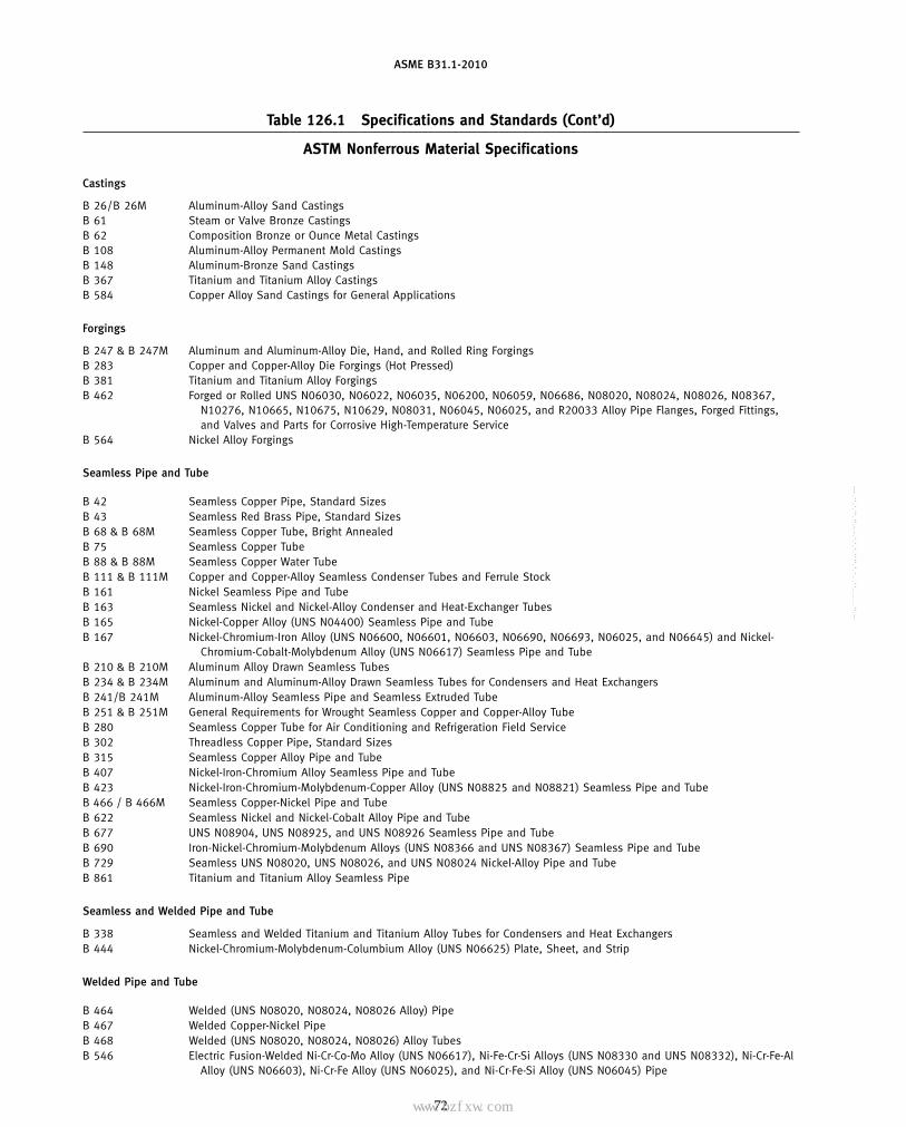
ASME B31.1-2010
Table 126.1 Specifications and Standards (Cont’d)
ASTM Nonferrous Material Specifications
Castings
B 26/B 26M Aluminum-Alloy Sand CastingsB 61 Steam or Valve Bronze CastingsB 62 Composition Bronze or Ounce Metal CastingsB 108 Aluminum-Alloy Permanent Mold CastingsB 148 Aluminum-Bronze Sand CastingsB 367 Titanium and Titanium Alloy CastingsB 584 Copper Alloy Sand Castings for General Applications
Forgings
B 247 & B 247M Aluminum and Aluminum-Alloy Die, Hand, and Rolled Ring ForgingsB 283 Copper and Copper-Alloy Die Forgings (Hot Pressed)B 381 Titanium and Titanium Alloy ForgingsB 462 Forged or Rolled UNS N06030, N06022, N06035, N06200, N06059, N06686, N08020, N08024, N08026, N08367,
N10276, N10665, N10675, N10629, N08031, N06045, N06025, and R20033 Alloy Pipe Flanges, Forged Fittings,and Valves and Parts for Corrosive High-Temperature Service
B 564 Nickel Alloy Forgings
Seamless Pipe and Tube
B 42 Seamless Copper Pipe, Standard SizesB 43 Seamless Red Brass Pipe, Standard SizesB 68 & B 68M Seamless Copper Tube, Bright AnnealedB 75 Seamless Copper TubeB 88 & B 88M Seamless Copper Water TubeB 111 & B 111M Copper and Copper-Alloy Seamless Condenser Tubes and Ferrule StockB 161 Nickel Seamless Pipe and TubeB 163 Seamless Nickel and Nickel-Alloy Condenser and Heat-Exchanger TubesB 165 Nickel-Copper Alloy (UNS N04400) Seamless Pipe and TubeB 167 Nickel-Chromium-Iron Alloy (UNS N06600, N06601, N06603, N06690, N06693, N06025, and N06645) and Nickel-
Chromium-Cobalt-Molybdenum Alloy (UNS N06617) Seamless Pipe and TubeB 210 & B 210M Aluminum Alloy Drawn Seamless TubesB 234 & B 234M Aluminum and Aluminum-Alloy Drawn Seamless Tubes for Condensers and Heat ExchangersB 241/B 241M Aluminum-Alloy Seamless Pipe and Seamless Extruded TubeB 251 & B 251M General Requirements for Wrought Seamless Copper and Copper-Alloy TubeB 280 Seamless Copper Tube for Air Conditioning and Refrigeration Field ServiceB 302 Threadless Copper Pipe, Standard SizesB 315 Seamless Copper Alloy Pipe and TubeB 407 Nickel-Iron-Chromium Alloy Seamless Pipe and TubeB 423 Nickel-Iron-Chromium-Molybdenum-Copper Alloy (UNS N08825 and N08821) Seamless Pipe and TubeB 466 / B 466M Seamless Copper-Nickel Pipe and TubeB 622 Seamless Nickel and Nickel-Cobalt Alloy Pipe and TubeB 677 UNS N08904, UNS N08925, and UNS N08926 Seamless Pipe and TubeB 690 Iron-Nickel-Chromium-Molybdenum Alloys (UNS N08366 and UNS N08367) Seamless Pipe and TubeB 729 Seamless UNS N08020, UNS N08026, and UNS N08024 Nickel-Alloy Pipe and TubeB 861 Titanium and Titanium Alloy Seamless Pipe
Seamless and Welded Pipe and Tube
B 338 Seamless and Welded Titanium and Titanium Alloy Tubes for Condensers and Heat ExchangersB 444 Nickel-Chromium-Molybdenum-Columbium Alloy (UNS N06625) Plate, Sheet, and Strip
Welded Pipe and Tube
B 464 Welded (UNS N08020, N08024, N08026 Alloy) PipeB 467 Welded Copper-Nickel PipeB 468 Welded (UNS N08020, N08024, N08026) Alloy TubesB 546 Electric Fusion-Welded Ni-Cr-Co-Mo Alloy (UNS N06617), Ni-Fe-Cr-Si Alloys (UNS N08330 and UNS N08332), Ni-Cr-Fe-Al
Alloy (UNS N06603), Ni-Cr-Fe Alloy (UNS N06025), and Ni-Cr-Fe-Si Alloy (UNS N06045) Pipe
72
Copyright ASME International Provided by IHS under license with ASME No reproduction or networking permitted without license from IHS
--`,,```````,,```,`,`,,,,`,`,`,`-`-`,,`,,`,`,,`---
标准分享网 www.bzfxw.com 免费下载

ASME B31.1-2010
Table 126.1 Specifications and Standards (Cont’d)
ASTM Nonferrous Material Specifications (Cont’d)
Welded Pipe and Tube (Cont’d)
(10)
B 547/B 547M Aluminum and Aluminum-Alloy Formed and Arc-Welded Round TubeB 608 Welded Copper-Alloy PipeB 619 Welded Nickel and Nickel-Cobalt Alloy PipeB 626 Welded Nickel and Nickel-Cobalt Alloy TubeB 673 UNS N08904, UNS N08925, and UNS N08926 Welded PipeB 674 UNS N08904, UNS N08925, and UNS N08926 Welded TubeB 675 UNS N08367 Welded PipeB 676 UNS N08367 Welded TubeB 704 Welded UNS N06625 and N08825 Alloy TubesB 705 Nickel-Alloy (UNS N06625 and N08825) Welded PipeB 804 UNS N08367 and UNS N08926 Welded PipeB 862 Titanium and Titanium Alloy Welded Pipe
Fittings
B 361 Factory-Made Wrought Aluminum and Aluminum-Alloy Welding FittingsB 366 Factory-Made Wrought Nickel and Nickel Alloy Fittings
Plate, Sheet, and Strip
B 168 Nickel-Chromium-Iron Alloys (UNS N06600, N06601, N06603, N06690, N06693, N06025, N06045) and Nickel-Chromium-Cobalt-Molybdenum Alloy (UNS N06617) Plate, Sheet, and Strip
B 171 Copper-Alloy Plate and Sheet for Pressure Vessels, Condensers, and Heat ExchangersB 209/B 209M Aluminum and Aluminum-Alloy Sheet and PlateB 265 Titanium and Titanium-Alloy Strip, Sheet, and PlateB 409 Nickel-Iron-Chromium Alloy Plate, Sheet, and StripB 424 Ni-Fe-Cr-Mo-Cu Alloy (UNS N08825 and N08221) Plate, Sheet, and StripB 435 UNS N06002, UNS N06230, UNS N12160, and UNS R30556 Plate, Sheet, and StripB 443 Nickel-Chromium-Molybdenum-Columbium Alloy (UNS N06625) Plate, Sheet, and StripB 463 UNS N08020, UNS N08026, and UNS N08024 Alloy Plate, Sheet, and StripB 625 UNS N08904, UNS N08925, UNS N08031, UNS N08932, UNS N08926, and UNS R20033 Plate, Sheet, and StripB 688 Chromium-Nickel-Molybdenum-Iron (UNS N08366 and UNS N08367) Plate, Sheet, and Strip
Rods, Bars, and Shapes
B 150 & B 150M Aluminum Bronze Rod, Bar, and ShapesB 151/B 151M Copper-Nickel-Zinc Alloy (Nickel Silver) and Copper-Nickel Rod and BarB 166 Nickel-Chromium-Iron Alloys (UNS N06600, N06601, N06603, N06690, N06693, N06025, and N06045) and
Nickel-Chromium-Cobalt-Molybdenum Alloy (UNS N06617) Rod, Bar, and WireB 221 & B 221M Aluminum and Aluminum Alloy Extruded Bars, Rods, Wire, Profiles, and TubesB 348 Titanium and Titanium Alloy Bars and BilletsB 408 Nickel-Iron-Chromium Alloy Rod and BarB 425 Ni-Fe-Cr-Mo-Cu Alloy (UNS N08825 and N08221) Rod and BarB 446 Nickel-Chromium Molybdenum-Columbium Alloy (UNS N06625) Rod and BarB 473 UNS N08020, UNS N08024, and UNS N08026 Nickel Alloy Bar and WireB 572 UNS N06002, UNS N06230, UNS N12160, and UNS R30556 RodB 649 Ni-Fe-Cr-Mo-Cu Low-Carbon Alloy (N08904), Ni-Fe-Cr-Mo-Cu-N Low-Carbon Alloys (UNS N08925, UNS N08031, and
UNS N08926), and Cr-Ni-Fe-N Low-Carbon Alloy (UNS R20033) Bar and WireB 691 Iron-Nickel-Chromium-Molybdenum Alloys (UNS N08366 and UNS N08367) Rod, Bar, and Wire
Solder
B 32 Solder MetalB 828 Standard Practice for Making Capillary Joints by Soldering of Copper and Copper Alloy Tube and Fittings
73
Copyright ASME International Provided by IHS under license with ASME No reproduction or networking permitted without license from IHS
--`,,```````,,```,`,`,,,,`,`,`,`-`-`,,`,,`,`,,`---
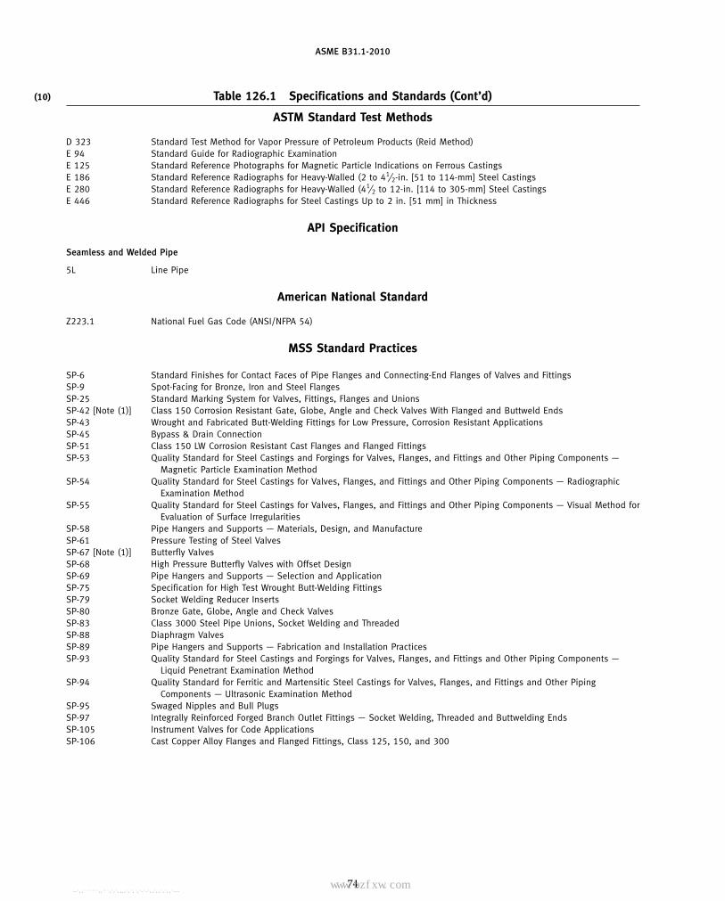
ASME B31.1-2010
Table 126.1 Specifications and Standards (Cont’d)(10)
ASTM Standard Test Methods
D 323 Standard Test Method for Vapor Pressure of Petroleum Products (Reid Method)E 94 Standard Guide for Radiographic ExaminationE 125 Standard Reference Photographs for Magnetic Particle Indications on Ferrous CastingsE 186 Standard Reference Radiographs for Heavy-Walled (2 to 41⁄2-in. [51 to 114-mm] Steel CastingsE 280 Standard Reference Radiographs for Heavy-Walled (41⁄2 to 12-in. [114 to 305-mm] Steel CastingsE 446 Standard Reference Radiographs for Steel Castings Up to 2 in. [51 mm] in Thickness
API Specification
Seamless and Welded Pipe
5L Line Pipe
American National Standard
Z223.1 National Fuel Gas Code (ANSI/NFPA 54)
MSS Standard Practices
SP-6 Standard Finishes for Contact Faces of Pipe Flanges and Connecting-End Flanges of Valves and FittingsSP-9 Spot-Facing for Bronze, Iron and Steel FlangesSP-25 Standard Marking System for Valves, Fittings, Flanges and UnionsSP-42 [Note (1)] Class 150 Corrosion Resistant Gate, Globe, Angle and Check Valves With Flanged and Buttweld EndsSP-43 Wrought and Fabricated Butt-Welding Fittings for Low Pressure, Corrosion Resistant ApplicationsSP-45 Bypass & Drain ConnectionSP-51 Class 150 LW Corrosion Resistant Cast Flanges and Flanged FittingsSP-53 Quality Standard for Steel Castings and Forgings for Valves, Flanges, and Fittings and Other Piping Components —
Magnetic Particle Examination MethodSP-54 Quality Standard for Steel Castings for Valves, Flanges, and Fittings and Other Piping Components — Radiographic
Examination MethodSP-55 Quality Standard for Steel Castings for Valves, Flanges, and Fittings and Other Piping Components — Visual Method for
Evaluation of Surface IrregularitiesSP-58 Pipe Hangers and Supports — Materials, Design, and ManufactureSP-61 Pressure Testing of Steel ValvesSP-67 [Note (1)] Butterfly ValvesSP-68 High Pressure Butterfly Valves with Offset DesignSP-69 Pipe Hangers and Supports — Selection and ApplicationSP-75 Specification for High Test Wrought Butt-Welding FittingsSP-79 Socket Welding Reducer InsertsSP-80 Bronze Gate, Globe, Angle and Check ValvesSP-83 Class 3000 Steel Pipe Unions, Socket Welding and ThreadedSP-88 Diaphragm ValvesSP-89 Pipe Hangers and Supports — Fabrication and Installation PracticesSP-93 Quality Standard for Steel Castings and Forgings for Valves, Flanges, and Fittings and Other Piping Components —
Liquid Penetrant Examination MethodSP-94 Quality Standard for Ferritic and Martensitic Steel Castings for Valves, Flanges, and Fittings and Other Piping
Components — Ultrasonic Examination MethodSP-95 Swaged Nipples and Bull PlugsSP-97 Integrally Reinforced Forged Branch Outlet Fittings — Socket Welding, Threaded and Buttwelding EndsSP-105 Instrument Valves for Code ApplicationsSP-106 Cast Copper Alloy Flanges and Flanged Fittings, Class 125, 150, and 300
74
Copyright ASME International Provided by IHS under license with ASME No reproduction or networking permitted without license from IHS
--`,,```````,,```,`,`,,,,`,`,`,`-`-`,,`,,`,`,,`---标准分享网 www.bzfxw.com 免费下载

ASME B31.1-2010
Table 126.1 Specifications and Standards (Cont’d)
ASME Codes & Standards
. . . ASME Boiler and Pressure Vessel CodeB1.1 Unified Inch Screw ThreadsB1.13M Metric Screw Threads — M ProfileB1.20.1 Pipe Threads, General Purpose (Inch)B1.20.3 Dryseal Pipe Threads (Inch)B16.1 Cast Iron Pipe Flanges and Flanged Fittings — 25, 125, 250 & 800 ClassesB16.3 Malleable Iron Threaded FittingsB16.4 Gray Iron Threaded FittingsB16.5 Pipe Flanges and Flanged FittingsB16.9 Factory-Made Wrought Buttwelding FittingsB16.10 Face-to-Face and End-to-End Dimensions of ValvesB16.11 Forged Fittings, Socket-Welding and ThreadedB16.14 Ferrous Pipe Plugs, Bushings, and Locknuts With Pipe ThreadsB16.15 Cast Bronze Threaded Fittings, Classes 125 and 250B16.18 Cast Copper Alloy Solder-Joint Pressure FittingsB16.20 Metallic Gaskets for Pipe Flanges — Ring Joint, Spiral Wound, and JacketedB16.21 Nonmetallic Flat Gaskets for Pipe FlangesB16.22 Wrought Copper and Copper Alloy Solder Joint Pressure FittingsB16.24 Cast Copper Alloy Pipe Flanges and Flanged Fittings — Class 150, 300, 400, 600, 900, 1500, and 2500B16.25 Butt Welding EndsB16.34 Valves — Flanged, Threaded, and Welding EndB16.42 Ductile Iron Pipe Flanges and Flanged Fittings — Classes 150 and 300B16.47 Large Diameter Steel FlangesB16.48 Steel Line BlanksB16.50 Wrought Copper and Copper Alloy Braze-Joint Pressure FittingsB18.2.1 Square and Hex Bolts and Screws — Inch SeriesB18.2.2 Square and Hex Nuts (Inch Series)B18.2.3.5M Metric Hex BoltsB18.2.3.6M Metric Heavy Hex BoltsB18.2.4.6M Hex Nuts, Heavy, MetricB18.21.1 Lock Washers (Inch Series)B18.22M Washers, Metric PlainB18.22.1 [Note (2)] Plain WashersB31.3 Process PipingB31.4 Pipeline Transportation Systems for Liquid Hydrocarbons and Other LiquidsB31.8 Gas Transmission and Distribution Piping SystemsB36.10M Welded and Seamless Wrought Steel PipeB36.19M Stainless Steel PipeTDP-1 Recommended Practices for the Prevention of Water Damage to Steam Turbines Used for Electric Power Generation —
Fossil Fueled Plants
AWS Specifications
A3.0 Standard Welding Terms and DefinitionsD10.10 Recommended Practices for Local Heating of Welds in Piping and TubingQC1 Qualification and Certification of Welding Inspectors
AWWA and ANSI/AWWA Standards
C110/A21.10 Ductile-Iron and Gray-Iron Fittings, 3 in. Through 48 in. (76 mm Through 1200 mm), for Water and Other LiquidsC111/A21.11 Rubber-Gasket Joints for Ductile-Iron Pressure Pipe and FittingsC115/A21.15 Flanged Ductile-Iron Pipe With Threaded FlangesC150/A21.50 Thickness Design of Ductile-Iron PipeC151/A21.51 Ductile-Iron Pipe, Centrifugally Cast, for WaterC153/A21.53 Ductile-Iron Compact Fittings, 3 in. Through 24 in. (76 mm Through 610 mm) and 54 in. Through 64 in. (1,400 mm
Through 1,600 mm), for Water Service
75
Copyright ASME International Provided by IHS under license with ASME No reproduction or networking permitted without license from IHS
--`,,```````,,```,`,`,,,,`,`,`,`-`-`,,`,,`,`,,`---

ASME B31.1-2010
Table 126.1 Specifications and Standards (Cont’d)
AWWA and ANSI/AWWA Standards (Cont’d)
C200 Steel Water Pipe—6 in. (150 mm) and LargerC207 Steel Pipe Flanges for Waterworks Service—Sizes 4 in. Through 144 in. (100 mm Through 3,600 mm)C208 Dimensions for Fabricated Steel Water Pipe FittingsC300 Reinforced Concrete Pressure Pipe, Steel-Cylinder Type, for Water and Other Liquids (Includes Addendum C300a-93.)C301 Prestressed Concrete Pressure Pipe, Steel-Cylinder Type, for Water and Other LiquidsC302 Reinforced Concrete Pressure Pipe, Noncylinder Type, for Water and Other LiquidsC304 Design of Prestressed Concrete Cylinder PipeC500 Metal-Seated Gate Valves for Water Supply ServiceC504 [Note (1)] Rubber Seated Butterfly ValvesC509 Resilient-Seated Gate Valves for Water Supply ServiceC600 Installation of Ductile-Iron Water Mains and Their AppurtenancesC606 Grooved and Shouldered Joints
National Fire Codes
NFPA 54/ANSI National Fuel Gas CodeZ223.1
NFPA 85 Boiler and Combustion Systems Hazards CodeNFPA 1963 Standard for Fire Hose Connections
PFI Standards
ES-16 Access Holes and Plugs for Radiographic Inspection of Pipe WeldsES-24 Pipe Bending Methods, Tolerances, Process and Material Requirements
FCI Standard
79-1 Proof of Pressure Ratings for Pressure Regulators
GENERAL NOTES:(a) For boiler external piping application, see para. 123.2.2.(b) For all other piping, materials conforming to an ASME SA or SB specification may be used interchangeably with material specified to an
ASTM A or B specification of the same number listed in Table 126.1.(c) The approved year of issue of the specifications and standards is not given in this Table. This information is given in Appendix F of
this Code.(d) The addresses and phone numbers of organizations whose specifications and standards are listed in this Table are given at the end of
Appendix F.
NOTES:(1) See para. 107.1(D) for valve stem retention requirements.(2) ANSI B18.22.1 is nonmetric.
76
Copyright ASME International Provided by IHS under license with ASME No reproduction or networking permitted without license from IHS
--`,,```````,,```,`,`,,,,`,`,`,`-`-`,,`,,`,`,,`---
标准分享网 www.bzfxw.com 免费下载

ASME B31.1-2010
Chapter VFabrication, Assembly, and Erection
127 WELDING
127.1 General
Piping systems shall be constructed in accordance withthe requirements of this Chapter and of materials thathave been manufactured in accordance with the require-ments of Chapter IV. These requirements apply to allfabrication, assembly, and erection operations, whetherperformed in a shop or at a construction site. The follow-ing applies essentially to the welding of ferrous materi-als. The welding of aluminum, copper, etc., requiresdifferent preparations and procedures.
127.1.1 The welding processes that are to be usedunder this part of this Code shall meet all the test require-ments of Section IX of the ASME Boiler and PressureVessel Code.
127.2 Material
127.2.1 Electrodes and Filler Metal. Welding elec-trodes and filler metal, including consumable inserts,shall conform to the requirements of the ASME Boilerand Pressure Vessel Code, Section II, Part C. An electrodeor filler metal not conforming to the above may be usedprovided the WPS and the welders and welding opera-tors who will follow the WPS have been qualified asrequired by ASME Section IX. Unless otherwise speci-fied by the designer, welding electrodes and filler metalsused shall produce weld metal that complies with thefollowing:
(A) The nominal tensile strength of the weld metalshall equal or exceed the minimum specified tensilestrength of the base metals being joined.
(B) If base metals of different tensile strengths are tobe joined, the nominal tensile strength of the weld metalshall equal or exceed the minimum specified tensilestrength of the weaker of the two.
(C) The nominal chemical analysis of the weld metalshall be similar to the nominal chemical analysis of themajor alloying elements of the base metal [e.g., 21⁄4% Cr,1% Mo steels should be joined using 21⁄4% Cr, 1% Mofiller metals; see also para. 124.2(D)].
(D) If base metals of different chemical analysis arebeing joined, the nominal chemical analysis of the weldmetal shall be similar to either base metal or an interme-diate composition, except as specified below for austen-itic steels joined to ferritic steels.
(E) When austenitic steels are joined to ferritic steels,the weld metal shall have an austenitic structure.
77
(F) For nonferrous metals, the weld metal shall bethat recommended by the manufacturer of the nonfer-rous metal or by industry associations for that metal.
(G) For unusual materials or combinations of materi-als, the design engineer shall specify the weld metal thatis required. In addition, when a base metal is selectedprimarily for its corrosion resistance, and the media isaggressive towards the material, the use of weld metalthat is electrochemically more noble than the base metalis recommended to ensure that selective corrosion of theweld metal does not occur (e.g., when using type 316Lbase metal in a strong acid, the use of 317L weld metalis preferred).
127.2.2 Backing Rings. Backing rings, when used,shall conform to the following requirements:
(A) Ferrous Rings. Ferrous metal backing rings thatbecome a permanent part of the weld shall be madefrom material of weldable quality, compatible with thebase material and the sulfur content shall not exceed0.05%.
(A.1) Backing rings may be of the continuousmachined or split band type.
(A.2) If two abutting surfaces are to be welded toa third member used as a backing ring and one or twoof the three members are ferritic and the other memberor members are austenitic, the satisfactory use of suchmaterials shall be determined by the WPS qualified asrequired in para. 127.5.
(A.3) Backing strips used at longitudinal weldedjoints shall be removed.
(B) Nonferrous and Nonmetallic Rings. Backing ringsof nonferrous or nonmetallic materials may be used forbacking provided they are included in a WPS as requiredin para. 127.5. Nonmetallic or nonfusing rings shall beremoved.
127.2.3 Consumable Inserts. Consumable insertsmay be used provided they are made from materialcompatible with the chemical and physical propertiesof the base material. Qualification of the WPS shall beas required by para. 127.5.
127.3 Preparation for Welding
(A) End Preparation(A.1) Oxygen or arc cutting is acceptable only if
the cut is reasonably smooth and true, and all slag iscleaned from the flame cut surfaces. Discoloration that
Copyright ASME International Provided by IHS under license with ASME No reproduction or networking permitted without license from IHS
--`,,```````,,```,`,`,,,,`,`,`,`-`-`,,`,,`,`,,`---

ASME B31.1-2010
Fig. 127.3 Butt Welding of Piping Components WithInternal Misalignment
30 degmax.
1/16 in. (2.0 mm) or less
Greater than 1/16 in. (2.0 mm)
may remain on the flame cut surface is not consideredto be detrimental oxidation.
(A.2) Butt-welding end preparation dimensionscontained in ASME B16.25 or any other end preparationthat meets the WPS are acceptable.
(A.3) If piping component ends are bored, such bor-ing shall not result in the finished wall thickness afterwelding less than the minimum design thickness. Wherenecessary, weld metal of the appropriate analysis maybe deposited on the inside or outside of the piping com-ponent to provide sufficient material for machining toinsure satisfactory fitting of rings.
(A.4) If the piping component ends are upset, theymay be bored to allow for a completely recessed backingring, provided the remaining net thickness of the fin-ished ends is not less than the minimum designthickness.
(B) Cleaning. Surfaces for welding shall be clean andshall be free from paint, oil, rust, scale, or other materialthat is detrimental to welding.
(C) Alignment. The inside diameters of piping com-ponents to be butt welded shall be aligned as accuratelyas is practicable within existing commercial toleranceson diameters, wall thicknesses, and out-of-roundness.Alignment shall be preserved during welding. The inter-nal misalignment of the ends to be joined shall notexceed 1⁄16 in. (2.0 mm) unless the piping design specifi-cally states a different allowable misalignment.
When the internal misalignment exceeds the allow-able, it is preferred that the component with the wallextending internally be internally trimmed perFig. 127.3. However, trimming shall result in a pipingcomponent thickness not less than the minimum designthickness, and the change in contour shall not exceed30 deg (see Fig. 127.3).
(D) Spacing. The root opening of the joint shall be asgiven in the WPS.
(E) Socket Weld Assembly. In assembly of the jointbefore welding, the pipe or tube shall be inserted into
78
the socket to the maximum depth and then withdrawnapproximately 1⁄16 in. (2.0 mm) away from contactbetween the end of the pipe and the shoulder of thesocket [see Figs. 127.4.4(B) and (C)]. In sleeve-type jointswithout internal shoulder, there shall be a distance ofapproximately 1⁄16 in. (2.0 mm) between the butting endsof the pipe or tube.
The fit between the socket and the pipe shall conformto applicable standards for socket weld fittings and inno case shall the inside diameter of the socket or sleeveexceed the outside diameter of the pipe or tube by morethan 0.080 in. (2.0 mm).
127.4 Procedure
127.4.1 General(A) Qualification of the WPS to be used, and of the
performance of welders and operators, is required, andshall comply with the requirements of para. 127.5.
(B) No welding shall be done if there is impingementof rain, snow, sleet, or high wind on the weld area.
(C) Tack welds permitted to remain in the finishedweld shall be made by a qualified welder. Tack weldsmade by an unqualified welder shall be removed. Tackwelds that remain shall be made with an electrode andWPS that is the same as or equivalent to the electrodeand WPS to be used for the first pass. The stopping andstarting ends shall be prepared by grinding or othermeans so that they can be satisfactorily incorporatedinto the final weld. Tack welds that have cracked shallbe removed.
(D) CAUTION: Arc strikes outside the area of theintended weld should be avoided on any base metal.
127.4.2 Girth Butt Welds(A) Girth butt welds shall be complete penetration
welds and shall be made with a single vee, double vee,or other suitable type of groove, with or without backingrings or consumable inserts. The depth of the weld mea-sured between the inside surface of the weld preparationand the outside surface of the pipe shall not be less thanthe minimum thickness required by Chapter II for theparticular size and wall of pipe used.
(B) To avoid abrupt transitions in the contour of thefinished weld, the requirements of (B.1) through (B.4)below shall be met.
(B.1) When components with different outsidediameters or wall thicknesses are welded together, thewelding end of the component with the larger outsidediameter shall fall within the envelope defined by solidlines in Fig. 127.4.2. The weld shall form a gradual transi-tion not exceeding a slope of 30 deg from the smallerto the larger diameter component. This condition maybe met by adding welding filler material, if necessary,beyond what would otherwise be the edge of the weld.
(B.2) When both components to be welded (otherthan pipe to pipe) have a transition from a thicker sectionto the weld end preparation, the included angle between
Copyright ASME International Provided by IHS under license with ASME No reproduction or networking permitted without license from IHS
--`,,```````,,```,`,`,,,,`,`,`,`-`-`,,`,,`,`,,`---标准分享网 www.bzfxw.com 免费下载

ASME B31.1-2010
Fig. 127.4.2 Welding End Transition — Maximum Envelope
1/2tm (min.) 11/2tm (min.)
30 deg max.
Maximum slope 1:3
Radius of at least 0.05tm
2tm (min.)
tm
Transition region
See Note (1)
See Note (2)
Radius not mandatory
Radius of at least 0.05tm
Maximum — See Note (3)Minimum — 1.0 tm
Component or fitting
Inside
Outside
45 deg max.
30 deg max.
GENERAL NOTES:(a) The value of tm is whichever of the following is applicable:
(1) as defined in para. 104.1.2(A)(2) the minimum ordered wall thickness of the cylindrical welding end of a component or fitting (or the thinner of the two) when the
joint is between two components(b) The maximum envelope is defined by solid lines.
NOTES:(1) Weld is shown for illustration only.(2) The weld transition and weld reinforcement shall comply with paras. 127.4.2(B) and (C.2) and may be outside the maximum envelope.(3) The maximum thickness at the end of the component is
(a) the greater of (tm + 0.15 in.) or 1.15tm when ordered on a minimum wall basis(b) the greater of (tm + 0.15 in.) or 1.10tnom when ordered on a nominal wall basis
79
Copyright ASME International Provided by IHS under license with ASME No reproduction or networking permitted without license from IHS
--`,,```````,,```,`,`,,,,`,`,`,`-`-`,,`,,`,`,,`---

ASME B31.1-2010
the surface of the weld and the surface of either of thecomponents shall not be less than 150 deg. Refer to para.119.3(B) for additional concerns related to this design.
(B.3) When welding pipe to pipe, the surface of theweld shall, as a minimum, be flush with the outer surfaceof the pipe, except as permitted in para. 127.4.2(B.4).
(B.4) For welds made without the addition of fillermetal, concavity shall be limited to 1⁄32 in. (1 mm) belowthe outside surface of the pipe, but shall not encroachupon minimum required thickness.
(C) As-welded surfaces are permitted; however, thesurface of welds shall be sufficiently free from coarseripples, grooves, overlaps, abrupt ridges, and valleys tomeet the following:
(C.1) The surface condition of the finished weldsshall be suitable for the proper interpretation of radio-graphic and other nondestructive examinations whennondestructive examinations are required byTable 136.4. In those cases where there is a questionregarding the surface condition on the interpretation ofa radiographic film, the film shall be compared to theactual weld surface for interpretation and determinationof acceptability.
(C.2) Reinforcements are permitted in accordancewith Table 127.4.2.
(C.3) Undercuts shall not exceed 1⁄32 in. (1.0 mm)and shall not encroach on the minimum required sectionthickness.
(C.4) If the surface of the weld requires grindingto meet the above criteria, care shall be taken to avoidreducing the weld or base material below the minimumrequired thickness.
(C.5) Concavity on the root side of a single weldedcircumferential butt weld is permitted when theresulting thickness of the weld is at least equal to thethickness of the thinner member of the two sectionsbeing joined and the contour of the concavity is smoothwithout sharp edges. The internal condition of the rootsurface of a girth weld, which has been examined byradiography, is acceptable only when there is a gradualchange in the density, as indicated in the radiograph.If a girth weld is not designated to be examined byradiography, a visual examination may be performed atwelds that are readily accessible.
127.4.3 Longitudinal Butt Welds. Longitudinal buttwelds not covered by the applicable material specifica-tions listed in Table 126.1 shall meet the requirementsfor girth butt welds in para. 127.4.2. For longitudinalwelds and spiral welds in pipe intended for sustainedoperation in the creep range (see paras. 104.1.1 and 123.4,and Table 102.4.7), any welding using the SAW processshall use a flux with a basicity index ≥ 1.0.
127.4.4 Fillet Welds. In making fillet welds, theweld metal shall be deposited in such a way as to secureadequate penetration into the base metal at the root ofthe weld.
80
Fillet welds may vary from convex to concave. The sizeof a fillet weld is determined as shown in Fig. 127.4.4(A).Typical minimum fillet weld details for slip-on flangesand socket-welding components are shown inFigs. 127.4.4(B) and (C).
127.4.5 Seal Welds. Where seal welding ofthreaded joints is performed, threads shall be entirelycovered by the seal weld. Seal welding shall be done byqualified welders.
127.4.8 Welded Branch Connections(A) Welded branch connections shall be made with
full penetration welds, except as allowed in para.127.4.8(F). Figures 127.4.8(A), (B), and (C) show typicaldetails of branch connections with and without addedreinforcement. No attempt has been made to show allacceptable types of construction and the fact that a cer-tain type of construction is illustrated does not indicatethat it is recommended over other types not illustrated.
(B) Figure 127.4.8(D) shows basic types of weldattachments used in the fabrication of branch connec-tions. The location and minimum size of these attach-ment welds shall conform to the requirements of para.127.4.8. Welds shall be calculated in accordance withpara. 104.3.1 but shall not be less than the sizes shownin Fig. 127.4.8(D).
The notations and symbols used in this paragraph,Fig. 127.4.8(D), and Fig. 127.4.8(E) are as follows:
tc p the smaller of 1⁄4 in. (6.0 mm) or 0.7tnbtmin p the smaller of tnb or tnr
tnb p nominal thickness of branch wall, in. (mm)tnh p nominal thickness of header wall, in. (mm)tnr p nominal thickness of reinforcing element (ring
or saddle), in. (mm)
(C) Figure 127.4.8(F) shows branch connections madeby welding half couplings or adapters directly to therun pipe.
Figure 127.4.8(E) shows branch connections using spe-cifically reinforced branch outlet fittings welded directlyto the run pipe. These branch connection fittings, halfcouplings, or adapters, which abut the outside surfaceof the run wall, or which are inserted through an openingcut in the run wall, shall have opening and branch con-tour to provide a good fit and shall be attached by meansof full penetration groove welds except as otherwisepermitted in (F) below.
The full penetration groove welds shall be finishedwith cover fillet welds and meet the requirements ofpara. 104. The cover fillet welds shall have a minimumthroat dimension not less than that shown inFig. 127.4.8(E) or Fig. 127.4.8(F), as applicable.
(D) In branch connections having reinforcement padsor saddles, the reinforcement shall be attached by weldsat the outer edge and at the branch periphery as follows:
(D.1) If the weld joining the added reinforcementto the branch is a full penetration groove weld, it shall
(10)
(10)
Copyright ASME International Provided by IHS under license with ASME No reproduction or networking permitted without license from IHS
--`,,```````,,```,`,`,,,,`,`,`,`-`-`,,`,,`,`,,`---标准分享网 www.bzfxw.com 免费下载

ASME B31.1-2010
Table 127.4.2 Reinforcement of Girth and Longitudinal Butt Welds
Maximum Thickness of Reinforcementfor Design Temperature
> 750°F 350°F–750°F < 350°F(400°C) (175°C–400°C) (175°C)Thickness of Base Metal,
in. (mm) in. mm in. mm in. mm
Up to 1⁄8 (3.0), incl. 1⁄16 2.0 3⁄32 2.5 3⁄16 5.0Over 1⁄8 to 3⁄16 (3.0 to 5.0), incl. 1⁄16 2.0 1⁄8 3.0 3⁄16 5.0Over 3⁄16 to 1⁄2 (5.0 to 13.0), incl. 1⁄16 2.0 5⁄32 4.0 3⁄16 5.0
Over 1⁄2 to 1 (13.0 to 25.0), incl. 3⁄32 2.5 3⁄16 5.0 3⁄16 5.0Over 1 to 2 (25.0 to 50.0), incl. 1⁄8 3.0 1⁄4 6.0 1⁄4 6.0Over 2 (50.0) 5⁄32 4.0 The greater of 1⁄4 in. (6 mm) or 1⁄8 times
the width of the weld in inches (millimeters).
GENERAL NOTES:(a) For double welded butt joints, this limitation on reinforcement given above shall apply separately to both inside and outside surfaces
of the joint.(b) For single welded butt joints, the reinforcement limits given above shall apply to the outside surface of the joint only.(c) The thickness of weld reinforcement shall be based on the thickness of the thinner of the materials being joined.(d) The weld reinforcement thicknesses shall be determined from the higher of the abutting surfaces involved.(e) Weld reinforcement may be removed if so desired.
81
Copyright ASME International Provided by IHS under license with ASME No reproduction or networking permitted without license from IHS
--`,,```````,,```,`,`,,,,`,`,`,`-`-`,,`,,`,`,,`---

ASME B31.1-2010
Fig. 127.4.4(A) Fillet Weld Size
The “size” of an equal leg fillet weld shall be described by the leg length of the largest inscribed isoceles triangle.The “size” of an unequal leg fillet weld shall be described using both leg lengths and their location on the members to be joined.Angle , as noted in the above figures, may vary from the 90 deg angle as shown based on the angle between the surfaces to be welded.For an equal leg fillet weld where the angle between the members being joined is 90 deg,the theoretical throat shall be 0.7 × leg length. For other fillet welds, the theoretical throat shall be based on the leg lengths and the angle between the members to be joined.For all fillet welds, particularly unequal leg fillet welds with angle less than 90 deg, the theoretical throat shall lie within the cross section of the deposited weld metal and shall not be less than the minimum distance through the weld.
Size ofweld
Size ofweld
Leg length
Leglength
θ Theoretical throat
(a) Convex Equal Leg
Fillet Weld
(b) Concave Equal Leg
Fillet Weld
GENERAL NOTES:(a)
(b)
(c)
(d)
(e)
θ
(d) Concave Unequal Leg
Fillet Weld
Leg length
Leglength
(c) Convex Unequal Leg
Fillet Weld
θθ
θ
θθ
θ
Theoretical throat
82
Copyright ASME International Provided by IHS under license with ASME No reproduction or networking permitted without license from IHS
--`,,```````,,```,`,`,,,,`,`,`,`-`-`,,`,,`,`,,`---标准分享网 www.bzfxw.com 免费下载

ASME B31.1-2010
Fig. 127.4.4(B) Welding Details for Slip-On and Socket-Welding Flanges; Some Acceptable Types of FlangeAttachment Welds
tn or 1/4 in. (6.0 mm),whichever is smaller
Approximately 1/16 in.(2.0 mm) before welding
(a) Front and Back Weld
[See Notes (1) and (2)]
(b) Face and Back Welds
[See Notes (1) and (2)]
(c) Socket Welding Flange
[See Notes (2) and (3)]
xmin.xmin.
xmin.xmin.
xmin.xmin.
tn p nominal pipe wall thicknessxmin. p 1.4tn or thickness of the hub, whichever is smaller
NOTES:(1) Refer to para. 122.1.1(F) for limitations of use.(2) Refer to para. 104.5.1 for limitations of use.(3) Refer to para. 122.1.1(H) for limitations of use.
Fig. 127.4.4(C) Minimum Welding DimensionsRequired for Socket Welding Components Other Than
Flanges
tn = nominal pipe wall thickness
Cx (min.) = 1.09tn or the thicknessof the socket wall,whichever is smaller
Cx
Cx
Approximately 1/16 in. (2.0 mm)before welding
Fig. 127.4.8(A) Typical Welded Branch ConnectionWithout Additional Reinforcement
83
Fig. 127.4.8(B) Typical Welded Branch ConnectionWith Additional Reinforcement
Vent hole
Fig. 127.4.8(C) Typical Welded Angular BranchConnection Without Additional Reinforcement
Copyright ASME International Provided by IHS under license with ASME
Not for Resale, 03/08/2011 00:55:16 MSTNo reproduction or networking permitted without license from IHS
--`,,```````,,```,`,`,,,,`,`,`,`-`-`,,`,,`,`,,`---

ASME B31.1-2010
Fig. 127.4.8(D) Some Acceptable Types of WeldedBranch Attachment Details Showing Minimum
Acceptable Welds
tnh
tnh
tnh
tnh
tnh
tnr
tnr
tnr
tnb
tnb
tnb
tnb
tnb
0.5tnr
0.5tnr
0.5tnr
0.7tmin
tc
tc
tc
tc
tc
GENERAL NOTE: Weld dimensions may be larger than theminimum values shown here.
(a)
(b)
(d)
(c)
(e)
84
Copyright ASME International Provided by IHS under license with ASME No reproduction or networking permitted without license from IHS
--`,,```````,,```,`,`,,,,`,`,`,`-`-`,,`,,`,`,,`---标准分享网 www.bzfxw.com 免费下载

ASME B31.1-2010
(10)Fig. 127.4.8(E) Some Acceptable Details for Integrally Reinforced Outlet Fittings
Manufacturer's weld line [Note (1)]
Bore may be straight or tapered as shown
C L b
ranc
hC L
bra
nch
C L b
ranc
h
CL branch
C L b
ranc
h
C L b
ranc
h
Manufacturer's weld line [Note (1)]
Manufacturer's weld line [Note (1)]
Manufacturer's weld line [Note (1)]
Manufacturer's weld line [Note (1)]
Manufacturer's weld line [Note (1)]
Manufacturer's weld line [Note (1)]
(1) Transverse View
(a) 90 deg Branch Fitting
(b) Elbow Branch Fitting
(c) Lateral Branch Fitting
(1) Transverse View
(1) Transverse View
(2) Longitudinal View
(2) Longitudinal View
(2) Longitudinal View
Cover weld [Note (3)]
Cover weld [Note (3)]
Angle [Note (2)]
Cover weld [Note (3)]
Cover weld [Note (3)]
Run pipe
Cover weld [Notes (2), (3)]
Heel area
Heel area
Elbow
Cover weld [Notes (2), (3)]
Cover weld [Note (2)]
Crotch area
Cover weld [Note (3)]
Crotch area
tc[Note (2)]
tc[Note (2)]
tc[Note (2)]
tnb[Note (4)]
tnb[Note (4)]
tnb[Note (4)]
tnb[Note (4)]
tnb[Note (4)]
tc
Angle[Note (2)]
tc[Note (2)]
Angle [Note (2)]
tc[Note (2)]
85
Copyright ASME International Provided by IHS under license with ASME No reproduction or networking permitted without license from IHS
--`,,```````,,```,`,`,,,,`,`,`,`-`-`,,`,,`,`,,`---

ASME B31.1-2010
(10) Fig. 127.4.8(E) Some Acceptable Details for Integrally Reinforced Outlet Fittings (Cont’d)
GENERAL NOTES;(a) Welds shall be in accordance with para. 127.4.8(C).(b) Weld attachment details for branch fittings that do not match the schedule or weight designation of the run pipe as defined by MSS
SP-97 Table 1 shall be designed to meet the requirements in paras. 104.3.1 and 104.7.2.(c) The stress intensification factors as required by paras. 104.8 and 119.7.3, for the fittings represented by drawings (b-1), (b-2), (c-1),
and (c-2), should be obtained from the fitting manufacturer.
NOTES;(1) When the fitting manufacturer has not provided a visible scribe line on the branch fitting, the weld line shall be the edge of the first
bevel on the branch fitting adjacent to the run pipe.(2) The minimum cover weld throat thickness, tc, applies when the angle between the branch fitting groove weld face and the run pipe
surface is less than 135 deg. For areas where the angle between the groove weld face and the run pipe surface is 135 deg or greater,the cover weld may transition to nothing.
(3) Cover weld shall provide a smooth transition to the run pipe.(4) tnb shall be measured at the longitudinal centerline of the branch fitting. When tnb in the crotch area does not equal tnb in the heel
area, the thicker of the two shall govern in determining the heat treatment in accordance with para. 132.4.
(10) Fig. 127.4.8(F) Typical Full Penetration Weld Branch Connections for NPS 3 and Smaller Half Couplings orAdapters
NOTE:(1) Refer to para. 104.3.1(C.2) for branch connections not requiring reinforcement calculations.
Socket-welding orthreaded half coupling
Socket-welding orthreaded adapter
Cover fillet weld Cover filletweld3/16 in. (5.0 mm) min.
3/16 in. (5 mm) min.
Full penetrationgroove weld
Full penetrationgroove weld
Header or run pipeHeader or run pipe
Bore after weldingPer WPS
(a) Branch Connection Using ASME B16.11
Forged Steel Socket-Welding or
Threaded Half Coupling [See Note (1)]
(b) Branch Connection Using Forged Steel Socket-Welding or
Threaded Adapter for Pressure and Temperature Conditions
Greater Than Permitted for ASME B16.11 Forged Steel Fittings
be finished with a cover fillet weld having a minimumthroat dimension not less than tc; the weld at the outeredge, joining the added reinforcement to the run, shall bea fillet weld with a minimum throat dimension of 0.5tnr.
(D.2) If the weld joining the added reinforcementto the branch is a fillet weld, the throat dimension shallnot be less than 0.7tmin. The weld at the outer edgejoining the outer reinforcement to the run shall also bea fillet weld with a minimum throat dimension of 0.5tnr.
(E) When rings or saddles are used, a vent hole shallbe provided (at the side and not at the crotch) in thering or saddle to reveal leakage in the weld betweenbranch and main run and to provide venting duringwelding and heat treating operations. Rings or saddlesmay be made in more than one piece if the joints between
86
the pieces have strength equivalent to ring or saddleparent metal and if each piece is provided with a venthole. A good fit shall be provided between reinforcingrings or saddles and the parts to which they are attached.
(F) Branch connections NPS 2 and smaller that do notrequire reinforcements (see para. 104.3) may be con-structed as shown in Fig. 127.4.8(G). The groove weldsshall be finished with cover fillet welds with a minimumthroat dimension not less than that shown inFig. 127.4.8(G). This construction shall not be used atdesign temperatures greater than 750°F (400°C) nor atdesign pressures greater than 1,025 psi (7 100 kPa).
127.4.9 Attachment Welds. Structural attachmentsmay be made by complete penetration, partial penetra-tion, or fillet welds.
(10)
Copyright ASME International Provided by IHS under license with ASME
Not for Resale, 03/08/2011 00:55:16 MSTNo reproduction or networking permitted without license from IHS
--`,,```````,,```,`,`,,,,`,`,`,`-`-`,,`,,`,`,,`---
标准分享网 www.bzfxw.com 免费下载
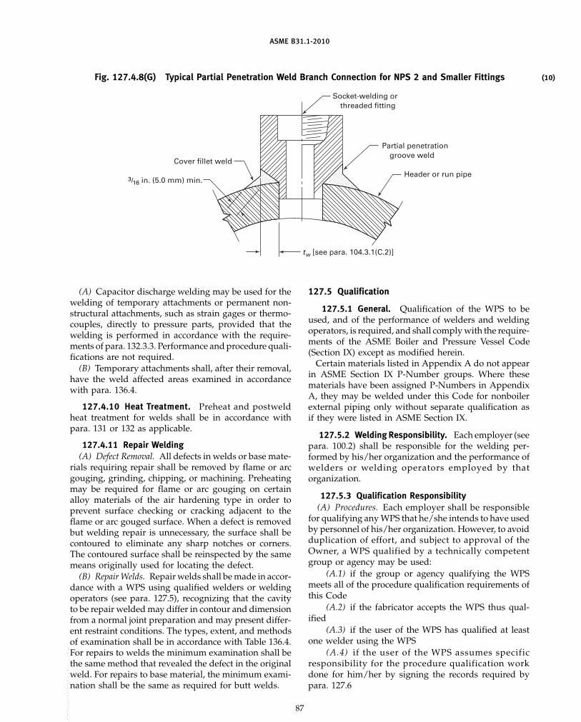
ASME B31.1-2010
(10)Fig. 127.4.8(G) Typical Partial Penetration Weld Branch Connection for NPS 2 and Smaller Fittings
3/16 in. (5.0 mm) min.
Partial penetrationgroove weld
Socket-welding orthreaded fitting
Cover fillet weld
Header or run pipe
tw [see para. 104.3.1(C.2)]
(A) Capacitor discharge welding may be used for thewelding of temporary attachments or permanent non-structural attachments, such as strain gages or thermo-couples, directly to pressure parts, provided that thewelding is performed in accordance with the require-ments of para. 132.3.3. Performance and procedure quali-fications are not required.
(B) Temporary attachments shall, after their removal,have the weld affected areas examined in accordancewith para. 136.4.
127.4.10 Heat Treatment. Preheat and postweldheat treatment for welds shall be in accordance withpara. 131 or 132 as applicable.
127.4.11 Repair Welding(A) Defect Removal. All defects in welds or base mate-
rials requiring repair shall be removed by flame or arcgouging, grinding, chipping, or machining. Preheatingmay be required for flame or arc gouging on certainalloy materials of the air hardening type in order toprevent surface checking or cracking adjacent to theflame or arc gouged surface. When a defect is removedbut welding repair is unnecessary, the surface shall becontoured to eliminate any sharp notches or corners.The contoured surface shall be reinspected by the samemeans originally used for locating the defect.
(B) Repair Welds. Repair welds shall be made in accor-dance with a WPS using qualified welders or weldingoperators (see para. 127.5), recognizing that the cavityto be repair welded may differ in contour and dimensionfrom a normal joint preparation and may present differ-ent restraint conditions. The types, extent, and methodsof examination shall be in accordance with Table 136.4.For repairs to welds the minimum examination shall bethe same method that revealed the defect in the originalweld. For repairs to base material, the minimum exami-nation shall be the same as required for butt welds.
87
127.5 Qualification
127.5.1 General. Qualification of the WPS to beused, and of the performance of welders and weldingoperators, is required, and shall comply with the require-ments of the ASME Boiler and Pressure Vessel Code(Section IX) except as modified herein.
Certain materials listed in Appendix A do not appearin ASME Section IX P-Number groups. Where thesematerials have been assigned P-Numbers in AppendixA, they may be welded under this Code for nonboilerexternal piping only without separate qualification asif they were listed in ASME Section IX.
127.5.2 Welding Responsibility. Each employer (seepara. 100.2) shall be responsible for the welding per-formed by his/her organization and the performance ofwelders or welding operators employed by thatorganization.
127.5.3 Qualification Responsibility(A) Procedures. Each employer shall be responsible
for qualifying any WPS that he/she intends to have usedby personnel of his/her organization. However, to avoidduplication of effort, and subject to approval of theOwner, a WPS qualified by a technically competentgroup or agency may be used:
(A.1) if the group or agency qualifying the WPSmeets all of the procedure qualification requirements ofthis Code
(A.2) if the fabricator accepts the WPS thus qual-ified
(A.3) if the user of the WPS has qualified at leastone welder using the WPS
(A.4) if the user of the WPS assumes specificresponsibility for the procedure qualification workdone for him/her by signing the records required bypara. 127.6
Copyright ASME International Provided by IHS under license with ASME
Not for Resale, 03/08/2011 00:55:16 MSTNo reproduction or networking permitted without license from IHS
--`,,```````,,```,`,`,,,,`,`,`,`-`-`,,`,,`,`,,`---

ASME B31.1-2010
All four of the above conditions shall be met before aWPS thus qualified may be used.
(B) Welders and Welding Operators. Each employershall be responsible for qualifying all the welders andwelding operators employed by him/her.
However, to avoid duplication of effort, he/she mayaccept a Welder/Welding Operator PerformanceQualification (WPQ) made by a previous employer (sub-ject to the approval of the Owner or his/her agent) onpiping using the same or an equivalent procedurewherein the essential variables are within the limitsestablished in Section IX, ASME Boiler and PressureVessel Code. An employer accepting such qualificationtests by a previous employer shall obtain a copy of theoriginal WPQ, showing the name of the employer bywhom the welders or welding operators were qualified,the dates of such qualification, and evidence that thewelder or welding operator has maintained qualificationin accordance with QW-322 of Section IX, ASME Boilerand Pressure Vessel Code. The evidence of process usageto maintain continuity may be obtained from employersother than the original qualifying employer. Theemployer shall then prepare and sign the record requiredin para. 127.6 accepting responsibility for the ability ofthe welder or welding operator.
127.5.4 Standard Welding ProcedureSpecifications. Standard Welding ProcedureSpecifications published by the American WeldingSociety and listed in Appendix E of Section IX of theASME Boiler and Pressure Vessel Code are permittedfor Code construction within the limitations establishedby Article V of ASME Section IX.
127.6 Welding RecordsThe employer shall maintain a record (WPS and/or
WPQ) signed by him/her, and available to the purchaseror his/her agent and the inspector, of the WPSs usedand the welders and/or welding operators employedby him/her, showing the date and results of procedureand performance qualification.
The WPQ shall also show the identification symbolassigned to the welder or welding operator employedby him/her, and the employer shall use this symbol toidentify the welding performed by the welder or weld-ing operator. This may be accomplished by the applica-tion of the symbol on the weld joint in a manner specifiedby the employer. Alternatively, the employer shall main-tain records that identify the weld(s) made by the welderor welding operator.
128 BRAZING AND SOLDERING128.1 General
128.1.1 The brazing processes that are to be usedunder this part of the Code shall meet all the test require-ments of Section IX of the ASME Boiler and PressureVessel Code.
88
128.1.2 Soldering. Solderers shall follow the proce-dure in ASTM B 828, Standard Practice for MakingCapillary Joints by Soldering of Copper and CopperAlloy Tube and Fittings.
128.2 Materials
128.2.1 Filler Metal. The brazing alloy or soldershall melt and flow freely within the specified or desiredtemperature range and, in conjunction with a suitableflux or controlled atmosphere, shall wet and adhere tothe surfaces to be joined.
128.2.2 Flux. A flux that is fluid and chemicallyactive at brazing or soldering temperature shall be usedwhen necessary to eliminate oxidation of the filler metaland the surfaces to be joined, and to promote free flowof the brazing alloy or solder.
128.3 Preparation
128.3.1 Surface Preparation. The surfaces to bebrazed or soldered shall be clean and free from grease,oxides, paint, scale, dirt, or other material that is detri-mental to brazing. A suitable chemical or mechanicalcleaning method shall be used if necessary to providea clean wettable surface.
128.3.2 Joint Clearance. The clearance between sur-faces to be joined by brazing or soldering shall be nolarger than is necessary to allow complete capillary dis-tribution of the brazing alloy or solder.
128.4 Procedure
128.4.1 General(A) Qualification of the brazing procedures to be used
and of the performance of the brazer and brazing opera-tors is required and shall comply with the requirementsof para. 128.5.
(B) No brazing shall be done if there is impingementof rain, snow, sleet, or high wind on the area to bebrazed.
128.4.2 Heating. To minimize oxidation, the jointshall be brought to brazing or soldering temperature inas short a time as possible without localized underheat-ing or overheating.
128.4.3 Flux Removal. Residual flux shall beremoved if detrimental.
128.5 Brazing Qualification
128.5.1 General. The qualification of the brazing-procedure and of the performance of brazers and brazingoperators shall be in accordance with the requirementsof Part QB, Section IX, ASME Boiler and Pressure VesselCode, except as modified herein.
128.5.2 Brazing Responsibility. Each employer (seepara. 100.2) shall be responsible for the brazing per-formed by his/her organization and the performance of
Copyright ASME International Provided by IHS under license with ASME No reproduction or networking permitted without license from IHS
--`,,```````,,```,`,`,,,,`,`,`,`-`-`,,`,,`,`,,`--- 标准分享网 www.bzfxw.com 免费下载
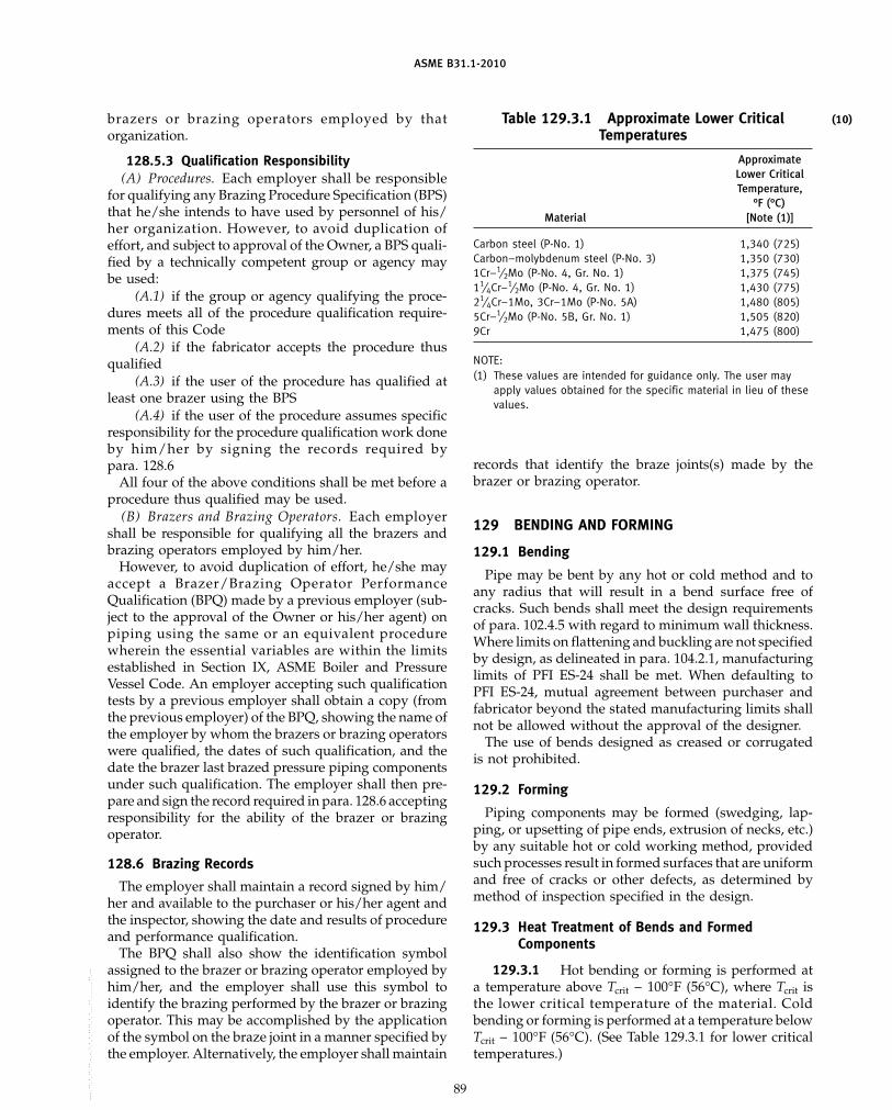
ASME B31.1-2010
brazers or brazing operators employed by thatorganization.
128.5.3 Qualification Responsibility(A) Procedures. Each employer shall be responsible
for qualifying any Brazing Procedure Specification (BPS)that he/she intends to have used by personnel of his/her organization. However, to avoid duplication ofeffort, and subject to approval of the Owner, a BPS quali-fied by a technically competent group or agency maybe used:
(A.1) if the group or agency qualifying the proce-dures meets all of the procedure qualification require-ments of this Code
(A.2) if the fabricator accepts the procedure thusqualified
(A.3) if the user of the procedure has qualified atleast one brazer using the BPS
(A.4) if the user of the procedure assumes specificresponsibility for the procedure qualification work doneby him/her by signing the records required bypara. 128.6
All four of the above conditions shall be met before aprocedure thus qualified may be used.
(B) Brazers and Brazing Operators. Each employershall be responsible for qualifying all the brazers andbrazing operators employed by him/her.
However, to avoid duplication of effort, he/she mayaccept a Brazer/Brazing Operator PerformanceQualification (BPQ) made by a previous employer (sub-ject to the approval of the Owner or his/her agent) onpiping using the same or an equivalent procedurewherein the essential variables are within the limitsestablished in Section IX, ASME Boiler and PressureVessel Code. An employer accepting such qualificationtests by a previous employer shall obtain a copy (fromthe previous employer) of the BPQ, showing the name ofthe employer by whom the brazers or brazing operatorswere qualified, the dates of such qualification, and thedate the brazer last brazed pressure piping componentsunder such qualification. The employer shall then pre-pare and sign the record required in para. 128.6 acceptingresponsibility for the ability of the brazer or brazingoperator.
128.6 Brazing Records
The employer shall maintain a record signed by him/her and available to the purchaser or his/her agent andthe inspector, showing the date and results of procedureand performance qualification.
The BPQ shall also show the identification symbolassigned to the brazer or brazing operator employed byhim/her, and the employer shall use this symbol toidentify the brazing performed by the brazer or brazingoperator. This may be accomplished by the applicationof the symbol on the braze joint in a manner specified bythe employer. Alternatively, the employer shall maintain
89
(10)Table 129.3.1 Approximate Lower CriticalTemperatures
ApproximateLower CriticalTemperature,
°F (°C)Material [Note (1)]
Carbon steel (P-No. 1) 1,340 (725)Carbon–molybdenum steel (P-No. 3) 1,350 (730)1Cr–1⁄2Mo (P-No. 4, Gr. No. 1) 1,375 (745)11⁄4Cr–1⁄2Mo (P-No. 4, Gr. No. 1) 1,430 (775)21⁄4Cr–1Mo, 3Cr–1Mo (P-No. 5A) 1,480 (805)5Cr–1⁄2Mo (P-No. 5B, Gr. No. 1) 1,505 (820)9Cr 1,475 (800)
NOTE:(1) These values are intended for guidance only. The user may
apply values obtained for the specific material in lieu of thesevalues.
records that identify the braze joints(s) made by thebrazer or brazing operator.
129 BENDING AND FORMING
129.1 Bending
Pipe may be bent by any hot or cold method and toany radius that will result in a bend surface free ofcracks. Such bends shall meet the design requirementsof para. 102.4.5 with regard to minimum wall thickness.Where limits on flattening and buckling are not specifiedby design, as delineated in para. 104.2.1, manufacturinglimits of PFI ES-24 shall be met. When defaulting toPFI ES-24, mutual agreement between purchaser andfabricator beyond the stated manufacturing limits shallnot be allowed without the approval of the designer.
The use of bends designed as creased or corrugatedis not prohibited.
129.2 Forming
Piping components may be formed (swedging, lap-ping, or upsetting of pipe ends, extrusion of necks, etc.)by any suitable hot or cold working method, providedsuch processes result in formed surfaces that are uniformand free of cracks or other defects, as determined bymethod of inspection specified in the design.
129.3 Heat Treatment of Bends and FormedComponents
129.3.1 Hot bending or forming is performed ata temperature above Tcrit − 100°F (56°C), where Tcrit isthe lower critical temperature of the material. Coldbending or forming is performed at a temperature belowTcrit − 100°F (56°C). (See Table 129.3.1 for lower criticaltemperatures.)
Copyright ASME International Provided by IHS under license with ASME No reproduction or networking permitted without license from IHS
--`,,```````,,```,`,`,,,,`,`,`,`-`-`,,`,,`,`,,`---

ASME B31.1-2010
129.3.2 A postbending or postforming heat treat-ment at the time and temperature cycles listed for post-weld heat treatment in Table 132 is required on all carbonsteel (P-No. 1) materials with a nominal wall thickness inexcess of 3⁄4 in. (19.0 mm) unless the bending or formingoperations are performed and completed at tempera-tures of 1,650°F (900°C) or greater.
129.3.3 A postforming or postbending heat treat-ment as defined below is required for all ferritic alloysteel (excluding P-No. 1) materials with a nominal pipesize 4 in. and larger or with a nominal thickness of 1⁄2 in.(13.0 mm) or greater.
(A) If hot bending or forming is performed, the mate-rial shall receive a full anneal, normalize and temper,or tempering heat treatment as specified by the designer.
(B) If cold bending or forming is performed, a heattreatment is required at the time and temperature cyclelisted for the material in Table 132.
129.3.4 Postbending or postforming heat treat-ment of other materials including austenitic stainlesssteel is neither required nor prohibited. If a postbendingor postforming heat treatment is to be performed, thedesigner shall fully describe the procedure to be used.
130 REQUIREMENTS FOR FABRICATING ANDATTACHING PIPE SUPPORTS
130.1 Pipe Supports
Standard pipe hangers and supports shall be fabri-cated in accordance with the requirements of MSS SP-58.Welders, welding operators, and WPSs shall be qualifiedin accordance with the requirements of the ASME Boilerand Pressure Vessel Code, Section IX.
130.2 Alternate Pipe Supports
Special hangers, supports, anchors, and guides, notdefined as standard types of hanger components inMSS SP-58, shall be welded in accordance with therequirements of para. 127 (para. 132 is not applicableexcept as required by the weld procedure used) andinspected in accordance with the requirements ofpara. 136.4.2.
130.3 Pipe Support Welds
Welds attaching hangers, supports, guides, andanchors to the piping system shall conform to therequirements of Chapters V and VI of this Code.
131 WELDING PREHEAT
131.1 Minimum Preheat Requirements
The preheat requirements listed herein are mandatoryminimum values.
The base metal temperature prior to welding shall beat or above the specified minimum temperature in alldirections from the point of welding for a distance of
90
3 in. or 1.5 times the base metal thickness (as definedin para. 131.4.1), whichever is greater.
The base metal temperature for tack welds shall beat or above the specified minimum temperature for adistance not less than 1 in. in all directions from thepoint of welding.
131.2 Different P-Number Materials
When welding two different P-Number materials, theminimum preheat temperature required shall be thehigher temperature for the material to be welded.
131.3 Preheat Temperature Verification
The preheat temperature shall be checked by use oftemperature-indicating crayons, thermocouple pyrome-ters, or other suitable methods to ensure that therequired preheat temperature is obtained prior to anduniformly maintained during the welding operation.
131.4 Preheat Temperature
The minimum preheat for all materials shall be 50°F(10°C) unless stated otherwise in the followingparagraphs.
131.4.1 Thickness referred to is the greater of thenominal thicknesses at the weld of the parts to be joined.
131.4.2 P-No. 1. 175°F (80°C) for material that hasboth a specified maximum carbon content in excess of0.30% and a thickness at the joint in excess of 1 in.(25.0 mm). Preheat may be based on the actual carboncontent as determined from a ladle or product analysisin accordance with the material specification in lieu ofthe maximum carbon content specified in the materialspecification.
131.4.3 P-No. 3. 175°F (80°C) for material or prod-uct form that has either a specified minimum tensilestrength in excess of 60,000 psi (413.7 MPa) or a thicknessat the joint in excess of 1⁄2 in. (13.0 mm).
131.4.4 P-No. 4. 250°F (120°C) for all materials.
131.4.5 P-Nos. 5A and 5B(A) 400°F (200°C) for material that has either a speci-
fied minimum tensile strength in excess of 60,000 psi(413.7 MPa), or has both a specified minimum chromiumcontent above 6.0% and a thickness at the joint in excessof 1⁄2 in. (13.0 mm)
(B) 300°F (150°C) for all other materials having thisP-Number
131.4.6 P-No. 6. 400°F (200°C) for all materials.
131.4.7 P-Nos. 9A and 9B(A) 250°F (120°C) for P-No. 9A materials(B) 300°F (150°C) for P-No. 9B materials
131.4.8 P-No. 10I. 300°F (150°C) with an interpasstemperature of 450°F (230°C) maximum.
131.4.9 P-No. 15E. 400°F (200°C) for all materials.
Copyright ASME International Provided by IHS under license with ASME No reproduction or networking permitted without license from IHS
--`,,```````,,```,`,`,,,,`,`,`,`-`-`,,`,,`,`,,`---
标准分享网 www.bzfxw.com 免费下载
(10)
ASME B31.1-2010
131.6 Interruption of Welding
131.6.1 After welding commences, the minimumpreheat temperature shall be maintained until anyrequired PWHT is performed on P-Nos. 3, 4, 5A, 5B, 6,and 15E, except when all of the following conditionsare satisfied:
(A) A minimum of at least 3⁄8 in. (9.5 mm) thicknessof weld is deposited or 25% of the welding groove isfilled, whichever is less (the weldment shall be suffi-ciently supported to prevent overstressing the weld ifthe weldment is to be moved or otherwise loaded).
(B) For P-Nos. 3, 4, and 5A (with a chromium contentof 3.0% maximum) materials, the weld is allowed to coolslowly to room temperature.
(C) For P-No. 5B (with a chromium content greaterthan 3.0%), P-No. 6, and P-No. 15E materials, the weldis subjected to an adequate intermediate heat treatmentwith a controlled rate of cooling. The preheat tempera-ture may be reduced to 200°F (93°C) (minimum) forthe purpose of root examination without performing anintermediate heat treatment.
(D) After cooling and before welding is resumed,visual examination of the weld shall be performed toassure that no cracks have formed.
(E) Required preheat shall be applied before weldingis resumed.
131.6.2 Intermediate heat treatment for P-No. 5Bor 15E materials may be omitted entirely when usinglow-hydrogen electrodes and filler metals classified bythe filler metal specification with an optional supple-mental diffusible-hydrogen designator of H8 or lowerand suitably controlled by maintenance procedures toavoid contamination by hydrogen-producing sources.The surface of the base metal prepared for welding shallbe free of contaminants.
132 POSTWELD HEAT TREATMENT
132.1 Minimum PWHT Requirements
132.1.1 Before applying the detailed requirementsand exemptions in these paragraphs, satisfactory qualifi-cation of the WPS to be used shall be performed inaccordance with the essential variables of the ASMEBoiler and Pressure Vessel Code, Section IX includingthe conditions of postweld heat treatment or lack ofpostweld heat treatment and including other restrictionslisted below. Except as otherwise provided in paras.132.2 and 132.3, all welds in materials included in theP-Numbers listed in Table 132 shall be given a postweldheat treatment within the temperature range specifiedin Table 132. (The range specified in Table 132 may bemodified by Table 132.1 for the lower limit and para.132.2 for the upper limit.) The materials in Table 132are listed in accordance with the material P-Numbergrouping of Appendix A. Welds of materials not
91
included in Table 132 shall be heat treated in accordancewith the WPS.
132.1.2 Pressure part welds and attachment weldsusing ferritic filler metals that have a specified chro-mium content of more than 3% shall receive a postweldheat treatment. The postweld heat treatment time andtemperature range used shall be that shown in Table 132for a base metal of similar composition.
132.2 Mandatory PWHT Requirements
Heat treatment may be accomplished by a suitableheating method that will provide the desired heatingand cooling rates, the required metal temperature, tem-perature uniformity, and temperature control.
(A) The upper limit of the PWHT temperature rangein Table 132 is a recommended value that may beexceeded provided the actual temperature does notexceed the lower critical temperature of either material(see Table 129.3.2).
(B) When parts of two different P-Numbers are joinedby welding, the postweld heat treatment shall be thatspecified for the material requiring the higher PWHTtemperature. When a nonpressure part is welded to apressure part and PWHT is required for either part,the maximum PWHT temperature shall not exceed themaximum temperature acceptable for the pressureretaining part.
(C) Caution is necessary to preclude metallurgicaldamage to some materials or welds not intended orqualified to withstand the PWHT temperaturesrequired.
132.3 Exemptions to Mandatory PWHT Requirements
132.3.1 Postweld heat treatment is not requiredfor the following conditions:
(A) welds in nonferrous materials(B) welds exempted in Table 132(C) welds subject to temperatures above the lower
critical temperature (see Table 129.3.2) during fabrica-tion provided the WPS has been qualified with PWHT(see para. 132.1) at the temperature range to be reachedduring fabrication
132.3.2 The postweld heat treatment exemptionof Table 132 may be based on the actual chemical compo-sition as determined by a ladle or product analysis inaccordance with the material specification in lieu of thespecified or maximum specified chemical compositionlimits.
132.3.3 Capacitor discharge welding may be usedfor welding temporary attachments and permanent non-structural attachments without subsequent postweldheat treatment on P-No. 1 through P-No. 5B materials,provided
Copyright ASME International Provided by IHS under license with ASME No reproduction or networking permitted without license from IHS
--`,,```````,,```,`,`,,,,`,`,`,`-`-`,,`,,`,`,,`---

ASME B31.1-2010
Table 132 Postweld Heat Treatment
Holding Time Based on Nominal ThicknessP-Number HoldingFrom Temperature Up to 2 in. Over 2 in.
Appendix A Range, °F (°C) (50 mm) (50 mm)
P-No. 1 1,100 (600) 1 hr/in. (25 mm), 2 hr plus 15 min for eachGr. Nos. 1, 2, 3 to 15 min minimum additional inch (25 mm) over
1,200 (650) 2 in. (50 mm)
GENERAL NOTES:(a) PWHT of P-No. 1 materials is not mandatory, provided that all of the following conditions are met:
(1) the nominal thickness, as defined in para. 132.4.1, is 3⁄4 in. (19.0 mm) or less(2) a minimum preheat of 200°F (95°C) is applied when the nominal material thickness of either of the base metals exceeds 1 in.
(25.0 mm)(b) PWHT of low hardenability P-No. 1 materials with a nominal material thickness, as defined in para. 132.4.3, over 3⁄4 in. (19.0 mm) but
not more than 11⁄2 in. (38 mm) is not mandatory, provided all of the following conditions are met:(1) the carbon equivalent, CE, is ≤ 0.50, using the formula
CE p C + (Mn + Si)/6 + (Cr + Mo + V)/5 + (Ni + Cu)/15
The maximum chemical composition limit from the material specification or actual values from a chemical analysis or material testreport shall be used in computing CE. If analysis for the last two terms is not available, 0.1% may be substituted for those two termsas follows:
CE p C + (Mn + Si)/6 + 0.1
(2) a minimum preheat of 250°F (121°C) is applied(3) the maximum weld deposit thickness of each weld pass shall not exceed 1⁄4 in. (6 mm)
(c) When it is impractical to PWHT at the temperature range specified in Table 132, it is permissible to perform the PWHT of this materialat lower temperatures for longer periods of time in accordance with Table 132.1.
Holding Time Based on Nominal ThicknessP-Number HoldingFrom Temperature Up to 2 in. Over 2 in.
Appendix A Range, °F (°C) (50 mm) (50 mm)
P-No. 3 1,100 (600) 1 hr/in. (25 mm), 2 hr plus 15 min for eachGr. Nos. 1, 2 to 15 min minimum additional inch (25 mm) over
1,200 (650) 2 in. (50 mm)
GENERAL NOTES:(a) PWHT of P-No. 3 materials is not mandatory, provided all of the following conditions are met:
(1) the nominal thickness, as defined in para. 132.4.1, is 5⁄8 in. (16.0 mm) or less(2) a minimum preheat of 200°F (95°C) is applied when the nominal material thickness of either of the base metals exceeds 5⁄8 in.
(16.0 mm)(3) the specified carbon content of the P-No. 3 base material is 0.25% or less
(b) When it is impractical to PWHT at the temperature range specified in Table 132, it is permissible to perform the PWHT of this materialat lower temperatures for longer periods of time in accordance with Table 132.1.
92
Copyright ASME International Provided by IHS under license with ASME No reproduction or networking permitted without license from IHS
--`,,```````,,```,`,`,,,,`,`,`,`-`-`,,`,,`,`,,`---
标准分享网 www.bzfxw.com 免费下载

ASME B31.1-2010
Table 132 Postweld Heat Treatment (Cont’d)
Holding Time Based on Nominal ThicknessP-Number HoldingFrom Temperature Up to 2 in. Over 2 in.
Appendix A Range, °F (°C) (50 mm) (50 mm)
P-No. 4 1,200 (650) 1 hr/in. (25 mm), 2 hr plus 15 min for eachGr. Nos. 1, 2 to 15 min minimum additional inch (25 mm) over
1,300 (700) 2 in. (50 mm)
GENERAL NOTE: PWHT is not mandatory for P-No. 4 material under the following conditions:(a) welds in pipe or attachment welds to pipe complying with all of the following conditions:
(1) a nominal material thickness of 1⁄2 in. (13.0 mm) or less(2) a specified carbon content of the material to be welded of 0.15% or less
(b) for seal welding of threaded or other mechanical joints, provided the seal weld has a throat thickness of 3⁄8 in. (9.0 mm) or less(c) attachment welds for nonload-carrying attachments provided in addition to (a)(2) above:
(1) stud welds or fillet welds made by the SMAW or GTAW process shall be used.(2) the hardened portion of the heat affected zone (HAZ) shall not encroach on the minimum wall thickness of the pipe, as determined
by welding procedure qualification using the maximum welding heat input. The depth of the HAZ shall be taken as the point where the HAZhardness does not exceed the average unaffected base metal hardness by more than 10%.
(3) if SMAW is used, the electrode shall be the low hydrogen type.(4) the thickness of the test plate used in making the welding procedure qualification of Section IX shall not be less than that of the
material to be welded.(5) the attachment weld has a throat thickness of 3⁄16 in. or less.
(d) for socket welded components and slip-on flange welds provided(1) the throat thickness is 1⁄2 in. (13 mm) or less(2) the wall thickness of the pipe is 1⁄2 in. (13 mm) or less(3) the specified carbon content of the pipe is 0.15% or less
Holding Time Based on Nominal ThicknessP-Number HoldingFrom Temperature Up to 2 in. Over 2 in.
Appendix A Range, °F (°C) (50 mm) (50 mm)
P-No. 5A 1,300 (700) 1 hr/in. (25 mm), 2 hr plus 15 min for eachGr. No. 1 to 15 min minimum additional inch (25 mm) over
1,400 (760) 2 in. (50 mm)
GENERAL NOTE: PWHT is not mandatory for P-No. 5A material under the following conditions:(a) welds in pipe or attachment welds to pipe complying with all of the following conditions:
(1) a nominal material thickness of 1⁄2 in. (13.0 mm) or less(2) a specified carbon content of the material to be welded of 0.15% or less
(b) for seal welding of threaded or other mechanical joints, provided the seal weld has a throat thickness of 3⁄8 in. (9.0 mm) or less(c) attachment welds for non-load-carrying attachments provided in addition to (a)(2) above:
(1) stud welds or fillet welds made by the SMAW or GTAW process shall be used.(2) the hardened portion of the heat affected zone (HAZ) shall not encroach on the minimum wall thickness of the pipe, as determined
by welding procedure qualification using the maximum welding heat input. The depth of the HAZ shall be taken as the point where the HAZhardness does not exceed the average unaffected base metal hardness by more than 10%.
(3) if SMAW is used, the electrode shall be the low hydrogen type.(4) the thickness of the test plate used in making the welding procedure qualification of Section IX shall not be less than that of the
material to be welded.(5) the attachment weld has a throat thickness of 3⁄16 in. or less.
(d) for socket welded components and slip-on flange welds provided(1) the throat thickness is 1⁄2 in. (13 mm) or less(2) the wall thickness of the pipe is 1⁄2 in. (13 mm) or less(3) the specified carbon content of the pipe is 0.15% or less
93
Copyright ASME International Provided by IHS under license with ASME No reproduction or networking permitted without license from IHS
--`,,```````,,```,`,`,,,,`,`,`,`-`-`,,`,,`,`,,`---

ASME B31.1-2010
Table 132 Postweld Heat Treatment (Cont’d)
Holding Time Based on Nominal ThicknessP-Number HoldingFrom Temperature Up to 2 in. Over 2 in.
Appendix A Range, °F (°C) (50 mm) (50 mm)
P-No. 5B 1,300 (700) 1 hr/in. (25 mm), 2 hr plus 15 minGr. No. 1 to 15 min minimum for each additional inch
1,400 (760) (25 mm) over 2 in.(50 mm)
Holding Time Based on Nominal ThicknessP-Number HoldingFrom Temperature Up to 2 in. Over 2 in.
Appendix A Range, °F (°C) (50 mm) (50 mm)
P-No. 6 1,400 (760) 1 hr/in. (25 mm), 2 hr plus 15 minGr. Nos. 1, 2, 3 to 15 min minimum for each additional inch
1,475 (800) (25 mm) over 2 in.(50 mm)
GENERAL NOTE: PWHT is not mandatory for P-No. 6 Type 410 material, provided all of the following conditions are met:(a) the specified carbon content is not more than 0.08%(b) the nominal material thickness is 3⁄8 in. (10 mm) or less(c) the weld is made with A-No. 8, A-No. 9, or F-No. 43 filler metal
94
Copyright ASME International Provided by IHS under license with ASME No reproduction or networking permitted without license from IHS
--`,,```````,,```,`,`,,,,`,`,`,`-`-`,,`,,`,`,,`---
标准分享网 www.bzfxw.com 免费下载

ASME B31.1-2010
Table 132 Postweld Heat Treatment (Cont’d)
Holding Time Based on Nominal ThicknessP-Number HoldingFrom Temperature Up to 2 in. Over 2 in.
Appendix A Range, °F (°C) (50 mm) (50 mm)
P-No. 7 1,350 (730) 1 hr/in. (25 mm), 2 hr plus 15 minGr. Nos. 1, 2 to 15 min minimum for each additional inch
1,425 (775) (25 mm) over 2 in.(50 mm)
GENERAL NOTES:(a) In lieu of the cooling rate described in para. 132.5, P-No. 7 material cooling rate shall be not greater than 100°F (55°C) per hr in the
range above 1,200°F (650°C), after which the cooling rate shall be sufficiently rapid to prevent embrittlement.(b) PWHT is not mandatory for P-No. 7 Type 405 material, provided all of the following conditions are met:
(1) the specified carbon content is not more than 0.08%(2) the nominal material thickness is 3⁄8 in. (10 mm) or less(3) the weld is made with A-No. 8, A-No. 9, or F-No. 43 filler metal
Holding Time Based on Nominal ThicknessP-Number HoldingFrom Temperature Up to 2 in. Over 2 in.
Appendix A Range, °F (°C) (50 mm) (50 mm)
P-No. 8 None None NoneGr. Nos. 1, 2, 3, 4
GENERAL NOTE: PWHT is neither required nor prohibited for joints between P-No. 8 austenitic stainless steels.
Holding Time Based on Nominal ThicknessP-Number HoldingFrom Temperature Up to 2 in. Over 2 in.
Appendix A Range, °F (°C) (50 mm) (50 mm)
P-No. 9A 1,100 (600) 1 hr/in. (25 mm), 2 hr plus 15 minGr. No. 1 to 15 min minimum for each additional inch
1,200 (650) (25 mm) over 2 in.(50 mm)
GENERAL NOTES:(a) PWHT is not mandatory for P-No. 9A material when welds on pipe or attachment welds to pipe comply with all of the following condi-
tions:(1) a nominal material thickness of 1⁄2 in. (13.0 mm) or less(2) a specified carbon content of the material to be welded of 0.15% or less(3) a minimum preheat of 250°F (120°C) is maintained during welding
(b) When it is impractical to PWHT at the temperature range specified in Table 132, it is permissible to perform the PWHT of this materialat lower temperatures for longer periods of time in accordance with Table 132.1, but the minimum PWHT shall not be less than1,000°F (550°C).
Holding Time Based on Nominal ThicknessP-Number Holding
From Temperature Up to 2 in. Over 2 in.Appendix A Range, °F (°C) (50 mm) (50 mm)
P-No. 9B 1,100 (600) 1 hr/in. (25 mm), 2 hr plus 15 minGr. No. 1 to 15 min minimum for each additional inch
1,175 (630) (25 mm) over 2 in.(50 mm)
GENERAL NOTES:(a) PWHT of P-No. 9B material is not mandatory for a nominal material thickness of 5⁄8 in. (16.0 mm) or less provided the Welding Proce-
dure Qualification has been made using material of thickness equal to or greater than the production weld.(b) When it is impractical to PWHT at the temperature range specified in Table 132, it is permissible to perform the PWHT of this material
at lower temperatures for longer periods of time in accordance with Table 132.1, but the minimum PWHT temperature shall not be lessthan 1,000°F (550°C).
95
Copyright ASME International Provided by IHS under license with ASME No reproduction or networking permitted without license from IHS
--`,,```````,,```,`,`,,,,`,`,`,`-`-`,,`,,`,`,,`---

ASME B31.1-2010
Table 132 Postweld Heat Treatment (Cont’d)
Holding Time Based on Nominal ThicknessP-Number Holding
From Temperature Up to 2 in. Over 2 in.Appendix A Range, °F (°C) (50 mm) (50 mm)
P-No. 10H . . . . . . . . .Gr. No. 1
GENERAL NOTE: Postweld heat treatment is neither required nor prohibited. If any heat treatment is performed after forming or welding, itshall be performed within the temperature range listed below for the particular alloy, followed by a rapid cool:
Alloy S31803 1,870°F–2,010°FAlloy S32550 1,900°F–2,050°FAlloy S32750 1,880°F–2,060°FAll others 1,800°F–1,900°F
Holding Time Based on Nominal ThicknessP-Number Holding
From Temperature Up to 2 in. Over 2 in.Appendix A Range, °F (°C) (50 mm) (50 mm)
P-No. 10I 1,350 (730) 1 hr/in. (25 mm), 1 hr/in. (25 mm)Gr. No. 1 to 15 min minimum
1,500 (815)
GENERAL NOTES:(a) In lieu of the cooling rate described in para. 132.5, the P-No. 10I material cooling rate shall be not greater than 100°F (55°C) per hr in
the range above 1,200°F (650°C), after which the cooling rate shall be sufficiently rapid to prevent embrittlement.(b) Postweld heat treatment is neither required nor prohibited for a nominal thickness of 1⁄2 in. (13 mm) or less.
96
Copyright ASME International Provided by IHS under license with ASME No reproduction or networking permitted without license from IHS
--`,,```````,,```,`,`,,,,`,`,`,`-`-`,,`,,`,`,,`---
标准分享网 www.bzfxw.com 免费下载

ASME B31.1-2010
Table 132 Postweld Heat Treatment (Cont’d)
Holding Time Based on Nominal ThicknessP-Number HoldingFrom Temperature Up to 5 in. Over 5 in.
Appendix A Range, °F (°C) (125 mm) (125 mm)
P-No. 15E 1,350 (730) 1 hr/in. (25 mm), 5 hr plus 15 min for eachGr. No. 1 to 30 min minimum additional inch
1,425 (775) (25 mm) over 5 in.(125 mm)
GENERAL NOTES:(a) If the nominal weld thickness is ≤ 1⁄2 in. (13 mm), the minimum holding temperature is 1,325°F (720°C).(b) For dissimilar metal welds (i.e., welds made between a P-No. 15E and another lower chromium ferritic, austenitic, or nickel-based
steel), if filler metal chromium content is less than 3.0% or if the filler metal is nickel-based or austenitic, the minimum holding tem-perature shall be 1,300°F (700°C).
(c) The maximum holding temperature above is to be used if the actual chemical composition of the matching filler metal used whenmaking the weld is unknown. If the chemical composition of the matching filler metal is known, the maximum holding temperature canbe increased as follows:
(1) If Ni + Mn < 1.50% but ≥ 1.0%, the maximum PWHT temperature is 1,450°F (790°C).(2) If Ni + Mn < 1.0%, the maximum PWHT temperature is 1,470°F (800°C).
Explanatory Note to (c) Above: The lower transformation temperature for matching filler material is affected by alloy content, primarilythe total of Ni + Mn. The maximum holding temperature has been set to avoid heat treatment in the intercritical zone.
(d) If a portion of the component is heated above the heat treatment temperature allowed above, one of the following actions shall beperformed:
(1) The component in its entirety must be renormalized and tempered.(2) If the maximum holding temperature in the Table or Note (c)(1) above is exceeded but does not exceed 1,470°F (800°C), the
weld metal shall be removed and replaced.(3) The portion of the component heated above 1,470°F (800°C) and at least 3 in. (75 mm) on either side of the overheated zone
must be removed and be renormalized and tempered or replaced.(4) The allowable stress shall be that for Grade 9 material (i.e., SA-213-T9, SA-335-P9, or equivalent product specification) at the
design temperature, provided that the portion of the component heated to a temperature greater than that allowed above is reheattreated within the temperature range specified above.
Table 132.1 Alternate Postweld Heat TreatmentRequirements for Carbon and Low Alloy Steels
Decrease in TemperaturesBelow Minimum Specified Minimum Holding Time at
Temperature, Decreased Temperature,°F (°C) hr [Note (1)]
50 (28) 2100 (56) 4150 (84) [Note (2)] 10200 (112) [Note (2)] 20
GENERAL NOTE: Postweld heat treatment at lower temperatures forlonger periods of time, in accordance with this Table, shall be usedonly where permitted in Table 132.
NOTES:(1) Times shown apply to thicknesses up to 1 in. (25 mm). Add
15 min/in. (15 min/25 mm) of thickness for thicknessesgreater than 1 in. (25 mm).
(2) A decrease of more than 100°F (56°C) below the minimumspecified temperature is allowable only for P-No. 1, Gr. Nos. 1and 2 materials.
97
(10)
Copyright ASME International Provided by IHS under license with ASME No reproduction or networking permitted without license from IHS
--`,,```````,,```,`,`,,,,`,`,`,`-`-`,,`,,`,`,,`---

(10)
ASME B31.1-2010
(A) a Welding Procedure Specification is prepared,describing the capacitor discharge equipment, the com-bination of materials to be joined, and the technique ofapplication; qualification of the welding procedure isnot required
(B) the energy output of the welding process is lim-ited to 125 W-sec
(C) for P-No. 5A and P-No. 5B materials, the maxi-mum carbon content of the material is 0.15%
132.4 Definition of Thickness Governing PWHT
132.4.1 The term nominal thickness as used inTable 132 and Notes is the lesser thickness of (A) or (B)as follows:
(A) the thickness of the weld(B) the thicker of the materials being joined at the
weld
132.4.2 Thickness of the weld, which is a factorin determining the nominal thickness, is defined asfollows:
(A) groove welds (girth and longitudinal) — thethicker of the two abutting ends after weld preparation,including I.D. machining
(B) fillet welds — the throat thickness of the weld(C) partial penetration welds — the depth of the weld
groove(D) material repair welds — the depth of the cavity
to be repaired(E) branch welds — the weld thickness is the dimen-
sion existing in the plane intersecting the longitudinalaxes and is calculated as indicated for each detail using
tc p the smaller of 1⁄4 in. or 0.7tnb
(1) for welds described in Fig. 127.4.8(D):
Detail (a)
weld thickness p tnb + tc
Detail (b)
weld thickness p tnh + tc
Detail (c)
weld thickness p greater of tnr + tc or tnb + tc
Detail (d)
weld thickness p tnh + tnr + tc
Detail (e)
weld thickness p tnb + tc
(2) for welds described in Fig. 127.4.8(E):
weld thickness p tnb + tc
98
(3) for welds described in Fig. 127.4.8(F) andFig. 127.4.8(G):
weld thickness p depth of groove weld+ throat thickness of cover fillet
132.4.3 The term nominal material thickness as usedin Table 132 is the thicker of the materials being joinedat the weld.
132.5 PWHT Heating and Cooling Requirements
Above 600°F (315°C), the rate of heating and coolingshall not exceed 600°F/hr (315°C/h) divided by one-half the maximum thickness of material in inches atthe weld, but in no case shall the rate exceed 600°F/hr(315°C/h). (See Table 132 for cooling rate requirementsfor P-Nos. 7 and 10I materials.)
132.6 Furnace Heating
(A) Heating an assembly in a furnace should be usedwhen practical; however, the size or shape of the unitor the adverse effect of a desired heat treatment on oneor more components where dissimilar materials areinvolved, may dictate alternative procedures such asheating a section before assembly, or by applying localheating in accordance with para. 132.7.
(B) An assembly may be postweld heat treated inmore than one heat in a furnace provided there is atleast a 1 ft (300 mm) overlap of the heated sectionsand the portion of the assembly outside the furnace isshielded so that the temperature gradient is not harmful.
(C) Direct impingement of flame on the assembly isprohibited.
132.7 Local Heating
Welds may be locally PWHT by heating a circumferen-tial band around the entire component with the weldlocated in the center of the band. The width of the bandheated to the PWHT temperature for girth welds shallbe at least three times the wall thickness at the weld ofthe thickest part being joined. For nozzle and attachmentwelds, the width of the band heated to the PWHT tem-perature shall extend beyond the nozzle weld or attach-ment weld on each side at least two times the headerthickness and shall extend completely around theheader. Guidance for the placement of thermocouples oncircumferential butt welds is provided in AWS D10.10,Sections 5, 6, and 8. Special consideration shall be givento the placement of thermocouples when heating weldsadjacent to large heat sinks such as valves or flanges,or when joining parts of differing thicknesses, to ensurethat no part of the materials subjected to the heat sourceexceeds the lower critical temperature of the material.Particular care must be exercised when the applicablePWHT temperature is close to the material’s lower criti-cal temperature, such as for creep strength enhancedferritic steels.
Copyright ASME International Provided by IHS under license with ASME No reproduction or networking permitted without license from IHS
--`,,```````,,```,`,`,,,,`,`,`,`-`-`,,`,,`,`,,`---
标准分享网 www.bzfxw.com 免费下载
ASME B31.1-2010
133 STAMPING
Stamping, if used, shall be performed by a methodthat will not result in sharp discontinuities. In no caseshall stamping infringe on the minimum wall thicknessor result in dimpling or denting of the material beingstamped.
CAUTIONARY NOTE: Detrimental effects can result fromstamping of material that will be in operation under long-termcreep or creep fatigue conditions.
135 ASSEMBLY
135.1 General
The assembly of the various piping components,whether done in a shop or as field erection, shall bedone so that the completely erected piping conformswith the requirements of the engineering design.
135.2 Alignment
135.2.1 Equipment Connections. When makingconnections to equipment, such as pumps or turbines orother piping components that are sensitive to externallyinduced loading, forcing the piping into alignment isprohibited if this action introduces end reactions thatexceed those permitted by design.
135.2.2 Cold Springs. Before assembling joints inpiping to be cold sprung, an examination shall be madeof guides, supports, and anchors for obstructions thatmight interfere with the desired movement or result inundesired movement. The gap or overlap of piping priorto assembly shall be checked against the design specifi-cations and corrected if necessary.
135.3 Bolted Flanged Connections
135.3.1 Fit Up. All flanged joints shall be fitted upso that the gasket contact surfaces bear uniformly onthe gasket and then shall be made up with relativelyuniform bolt stress.
135.3.2 Gasket Compression. When bolting gas-keted flange joints, the gasket shall be properly com-pressed in accordance with the design principlesapplicable to the type of gasket being used.
135.3.3 Cast Iron to Steel Joints. Cast iron to steelflanged joints in accordance with para 108.3 shall beassembled with care to prevent damage to the cast ironflange.
99
135.3.4 Bolt Engagement. All bolts shall beengaged so that there is visible evidence of completethreading through the nut or threaded attachment.
135.3.5 Nonmetallic Lined Joints. When assemblingnonmetallic lined joints, such as plastic lined steel pipe,consideration should be given to maintaining electricalcontinuity between flanged pipe sections whererequired.
135.4 Packed Joints and Caulked Joints
Care shall be used to ensure adequate engagement ofjoint members. Where packed joints are used to absorbthermal expansion, proper clearance shall be providedat the bottom of the sockets to permit movement.
135.5 Threaded Piping
135.5.1 Thread Compound. Any compound orlubricant used in threaded joints shall be suitable forthe service conditions, and shall be compatible with thepiping material and the service fluid.
135.5.2 Joints for Seal Welding. Threaded jointsthat are intended to be seal welded in accordance withpara. 127.4.5 should be made up without any threadcompound.
135.5.3 Joints Using Straight Threads. Some jointsusing straight threads, with sealing at a surface otherthan threads, are shown in Fig. 135.5.3. Care shall beused to avoid distorting the seal when incorporatingsuch joints into piping assemblies by welding or brazing.
135.5.4 Backing Off. Backing off threaded joints toallow for alignment is prohibited.
135.6 Tubing Joints
135.6.1 Flared. The sealing surface shall be free ofinjurious defects before installation.
135.6.2 Flareless and Compression. Flareless andcompression joints shall be assembled in accordancewith manufacturer’s recommendations.
135.7 Ductile Iron Bell End Piping
Assembly of ductile iron pipe, using ANSI/AWWAC111/A21.11 mechanical or push-on joints, shall complywith AWWA C600.
Copyright ASME International Provided by IHS under license with ASME No reproduction or networking permitted without license from IHS
--`,,```````,,```,`,`,,,,`,`,`,`-`-`,,`,,`,`,,`---

ASME B31.1-2010
Fig. 135.5.3 Typical Threaded Joints Using Straight Threads
Gasket or O-ring
Gasket or O-ring
GENERAL NOTE: Threads are ASME B1.1 straight threads.
(a) (b) (c)
100
Copyright ASME International Provided by IHS under license with ASME No reproduction or networking permitted without license from IHS
--`,,```````,,```,`,`,,,,`,`,`,`-`-`,,`,,`,`,,`---标准分享网 www.bzfxw.com 免费下载
ASME B31.1-2010
Chapter VIInspection, Examination, and Testing
136 INSPECTION AND EXAMINATION
136.1 Inspection
136.1.1 General. This Code distinguishes between“examination” and “inspection.” Inspection is theresponsibility of the Owner and may be performed byemployees of the Owner or a party authorized by theOwner, except for the inspections required by para.136.2. Prior to initial operation, a piping installation shallbe inspected to ensure compliance with the engineeringdesign and with the material, fabrication, assembly,examination, and test requirements of this Code.
136.1.2 Verification of Compliance. Compliancewith the requirements of this Code shall be verified byan Authorized Inspector when a Code stamp is requiredby Section I of the ASME Boiler and Pressure VesselCode. The rules of this Code and the quality controlsystem requirements of Appendix A-300 of Section I ofthe ASME Boiler and Pressure Vessel Code shall apply.The quality control system requirements are shown inAppendix J of this Code. The duty of the Inspector shallbe as defined in PG-90, Section I, of the ASME Boiler andPressure Vessel Code. Data Report Forms are included inthe Appendix of ASME Section I for use in developingthe necessary inspection records. The Inspector shallassure himself/herself that the piping has been con-structed in accordance with the applicable requirementsof this Code.
136.1.3 Rights of Inspectors. Inspectors shall haveaccess to any place where work concerned with thepiping is being performed. This includes manufacture,fabrication, heat treatment, assembly, erection, examina-tion, and testing of the piping. They shall have the rightto audit any examination, to inspect the piping usingany appropriate examination method required by theengineering design or this Code, and to review all certifi-cations and records necessary to satisfy the Owner’sresponsibility as stated in para. 136.1.1.
136.1.4 Qualifications of the Owner’s Inspector(A) The Owner’s Inspector shall be designated by the
Owner and shall be an employee of the Owner, anemployee of an engineering or scientific organization,or of a recognized insurance or inspection companyacting as the Owner’s agent. The Owner’s Inspector shallnot represent nor be an employee of the piping manufac-turer, fabricator, or erector unless the Owner is also themanufacturer, fabricator, or erector.
101
(B) The Owner’s Inspector shall have not less than10 years of experience in the design, manufacture, erec-tion, fabrication, or inspection of power piping. Eachyear of satisfactorily completed work toward an engi-neering degree recognized by the Accreditation Boardfor Engineering and Technology shall be consideredequivalent to 1 year of experience, up to 5 years total.
(C) In delegating the performance of inspections, theOwner is responsible for determining that a person towhom an inspection function is delegated is qualifiedto perform that function.
136.2 Inspection and Qualification of AuthorizedInspector for Boiler External Piping
136.2.1 Piping for which inspection and stampingis required as determined in accordance with para.100.1.2(A) shall be inspected during construction andafter completion and at the option of the AuthorizedInspector at such stages of the work as he/she maydesignate. For specific requirements see the applicableparts of Section I of the ASME Boiler and Pressure VesselCode, PG-104 through PG-113. Each manufacturer, fabri-cator, or assembler is required to arrange for the servicesof Authorized Inspectors.
136.2.1.1 The inspections required by thisSection shall be performed by an Inspector employedby an ASME accredited Authorized Inspection Agency.
136.2.2 Certification by stamping and DataReports, where required, shall be as per PG-104, PG-105,PG-109, PG-110, PG-111, and PG-112 of Section I of theASME Boiler and Pressure Vessel Code.
136.3 Examination
136.3.1 General. Examination denotes the func-tions performed by the manufacturer, fabricator, erector,or a party authorized by the Owner that include nonde-structive examinations (NDE), such as visual, radiogra-phy, ultrasonic, eddy current, liquid penetrant, andmagnetic particle methods. The degree of examinationand the acceptance standards beyond the requirementsof this Code shall be a matter of prior agreement betweenthe manufacturer, fabricator, or erector and the Owner.
136.3.2 Qualification of NDE Personnel. Personnelwho perform nondestructive examination of welds shallbe qualified and certified for each examination methodin accordance with a program established by the
Copyright ASME International Provided by IHS under license with ASME No reproduction or networking permitted without license from IHS
--`,,```````,,```,`,`,,,,`,`,`,`-`-`,,`,,`,`,,`---

ASME B31.1-2010
employer of the personnel being certified, which shallbe based on the following minimum requirements:
(A) instruction in the fundamentals of the nonde-structive examination method.
(B) on-the-job training to familiarize the NDE person-nel with the appearance and interpretation of indica-tions of weld defects. The length of time for such trainingshall be sufficient to ensure adequate assimilation of theknowledge required.
(C) an eye examination performed at least once eachyear to determine optical capability of NDE personnelto perform the required examinations.
(D) upon completion of (A) and (B) above, the NDEpersonnel shall be given an oral or written examinationand performance examination by the employer to deter-mine if the NDE personnel are qualified to perform therequired examinations and interpretation of results.
(E) certified NDE personnel whose work has notincluded performance of a specific examination methodfor a period of 1 yr or more shall be recertified by success-fully completing the examination of (D) above and alsopassing the visual examination of (C) above. Substantialchanges in procedures or equipment shall require recer-tification of the NDE personnel.
As an alternative to the preceding program, therequirements of the ASME Boiler and Pressure VesselCode, Section V, Article 1 may be used for the qualifica-tion of NDE personnel. Personnel qualified to AWS QC1may be used for the visual examination of welds.
136.4 Examination Methods of Welds
136.4.1 Nondestructive Examination. Nondestruc-tive examinations shall be performed in accordance withthe requirements of this Chapter. The types and extentof mandatory examinations for pressure welds andwelds to pressure retaining components are specifiedin Table 136.4. For welds other than those covered byTable 136.4, only visual examination is required. Weldsrequiring nondestructive examination shall comply withthe applicable acceptance standards for indications asspecified in paras. 136.4.2 through 136.4.6. As a guide,the detection capabilities for the examination methodare shown in Table 136.4.1. Welds not requiring examina-tion (i.e., RT, UT, MT, or PT) by this Code or the engi-neering design shall be judged acceptable if they meetthe examination requirements of para. 136.4.2 and thepressure test requirements specified in para. 137. NDEfor P-Nos. 3, 4, 5A, 5B, and 15E material welds shall beperformed after postweld heat treatment unless directedotherwise by engineering design. Required NDE forwelds in all other materials may be performed beforeor after postweld heat treatment.
136.4.2 Visual Examination. Visual examination asdefined in para. 100.2 shall be performed in accordancewith the methods described in Section V, Article 9, of
102
the ASME Boiler and Pressure Vessel Code. Visual exam-inations may be conducted, as necessary, during thefabrication and erection of piping components to pro-vide verification that the design and WPS requirementsare being met. In addition, visual examination shall beperformed to verify that all completed welds in pipeand piping components comply with the acceptancestandards specified in (A) below or with the limitationson imperfections specified in the material specificationunder which the pipe or component was furnished.
(A) Acceptance Standards. The following indicationsare unacceptable:
(A.1) cracks — external surface.(A.2) undercut on surface that is greater than 1⁄32 in.
(1.0 mm) deep.(A.3) weld reinforcement greater than specified in
Table 127.4.2.(A.4) lack of fusion on surface.(A.5) incomplete penetration (applies only when
inside surface is readily accessible).(A.6) any other linear indications greater than 3⁄16 in.
(5.0 mm) long.(A.7) surface porosity with rounded indications
having dimensions greater than 3⁄16 in. (5.0 mm) or fouror more rounded indications separated by 1⁄16 in.(2.0 mm) or less edge to edge in any direction. Roundedindications are indications that are circular or ellipticalwith their length less than three times their width.
136.4.3 Magnetic Particle Examination. Wheneverrequired by this Chapter (see Table 136.4), magneticparticle examination shall be performed in accordancewith the methods of Article 7, Section V, of the ASMEBoiler and Pressure Vessel Code.
(A) Evaluation of Indications(A.1) Mechanical discontinuities at the surface will
be indicated by the retention of the examinationmedium. All indications are not necessarily defects;however, certain metallurgical discontinuities and mag-netic permeability variations may produce similar indi-cations that are not relevant to the detection ofunacceptable discontinuities.
(A.2) Any indication that is believed to be nonrele-vant shall be reexamined to verify whether or not actualdefects are present. Surface conditioning may precedethe reexamination. Nonrelevant indications that wouldmask indications of defects are unacceptable.
(A.3) Relevant indications are those that result fromunacceptable mechanical discontinuities. Linear indica-tions are those indications in which the length is morethan three times the width. Rounded indications areindications that are circular or elliptical with the lengthless than three times the width.
(A.4) An indication of a discontinuity may be largerthan the discontinuity that causes it; however, the sizeof the indication and not the size of the discontinuityis the basis of acceptance or rejection.
Copyright ASME International Provided by IHS under license with ASME No reproduction or networking permitted without license from IHS
--`,,```````,,```,`,`,,,,`,`,`,`-`-`,,`,,`,`,,`---
标准分享网 www.bzfxw.com 免费下载

ASME B31.1-2010
Tabl
e13
6.4
Man
dato
ryM
inim
umN
onde
stru
ctiv
eEx
amin
atio
nsfo
rPr
essu
reW
elds
orW
elds
toPr
essu
re-R
etai
ning
Com
pone
nts
Pipi
ngD
esig
nCo
ndit
ions
and
Non
dest
ruct
ive
Exam
inat
ion
Tem
pera
ture
sB
etw
een
350°
F(1
75°C
)an
d75
0°F
(400
°C)
Tem
pera
ture
sO
ver
750°
FIn
clus
ive,
Wit
hA
llPr
essu
res
(400
°C)
and
atA
llO
ver
1,02
5ps
ig[7
100
kPa
Type
Wel
dPr
essu
res
(gag
e)]
All
Oth
ers
But
tw
elds
(gir
than
dlo
ngitu
di-
RTor
UT
for
over
NPS
2.RT
orU
Tfo
rov
erN
PS2
Visu
alfo
ral
lsi
zes
and
nal)
[Not
e(1
)]M
Tor
PTfo
rN
PS2
and
wit
hth
ickn
ess
over
3 ⁄ 4in
.th
ickn
esse
sle
ss[N
ote
(2)]
.(1
9.0
mm
).V
Tfo
ral
lsi
zes
wit
hth
ickn
ess
3 ⁄ 4in
.(1
9.0
mm
)or
less
.
Wel
ded
bran
chco
nnec
tion
s(s
ize
RTor
UT
for
over
NPS
4.RT
orU
Tfo
rbr
anch
over
NPS
4V
Tfo
ral
lsi
zes
and
indi
cate
dis
bran
chsi
ze)
[Not
esM
Tor
PTfo
rN
PS4
and
and
thic
knes
sof
bran
chov
erth
ickn
esse
s(3
)an
d(4
)]le
ss[N
ote
(2)]
.3 ⁄ 4
in.
(19.
0m
m)
MT
orPT
for
bran
chN
PS4
and
less
wit
hth
ickn
ess
ofbr
anch
over
3 ⁄ 4in
.(1
9m
m)
VT
for
all
size
sw
ith
bran
chth
ickn
ess
3 ⁄ 4in
.(1
9.0
mm
)or
less
Fille
t,so
cket
,at
tach
men
t,PT
orM
Tfo
ral
lsi
zes
and
VT
for
all
size
san
dV
Tfo
ral
lsi
zes
and
and
seal
wel
dsth
ickn
esse
s[N
ote
(5)]
thic
knes
ses
thic
knes
ses
GEN
ERA
LN
OTE
S:
(a)
All
wel
dssh
all
begi
ven
avi
sual
exam
inat
ion
inad
diti
onto
the
type
ofsp
ecifi
cno
ndes
truc
tive
exam
inat
ion
spec
ified
.(b
)N
PS—
nom
inal
pipe
size
.(c
)RT
—ra
diog
raph
icex
amin
atio
n;U
T—
ultr
ason
icex
amin
atio
n;M
T—
mag
neti
cpa
rtic
leex
amin
atio
n;PT
—liq
uid
pene
tran
tex
amin
atio
n;V
T—
visu
alex
amin
atio
n.(d
)Fo
rno
ndes
truc
tive
exam
inat
ions
ofth
epr
essu
rere
tain
ing
com
pone
nt,
refe
rto
the
stan
dard
slis
ted
inTa
ble
126.
1or
man
ufac
turi
ngsp
ecifi
cati
ons.
(e)
Acc
epta
nce
stan
dard
sfo
rno
ndes
truc
tive
exam
inat
ions
perf
orm
edar
eas
follo
ws:
MT
—se
epa
ra.
136.
4.3;
PT—
see
para
.13
6.4.
4;V
T—
see
para
.13
6.4.
2;RT
—se
epa
ra.
136.
4.5;
UT
—se
epa
ra.
136.
4.6.
(f)
All
long
itudi
nal
wel
dsan
dsp
iral
wel
dsin
pipe
inte
nded
for
sust
aine
dop
erat
ion
inth
ecr
eep
rang
e(s
eepa
ras.
104.
1.1
and
123.
4,an
dTa
ble
102.
4.7)
mus
tre
ceiv
ean
dpa
ssa
100%
volu
met
ric
exam
inat
ion
(RT
orU
T)pe
rth
eap
plic
able
mat
eria
lsp
ecifi
cati
onor
inac
cord
ance
wit
hpa
ra.
136.
4.5
or13
6.4.
6.
NO
TES
:(1
)Th
eth
ickn
ess
ofbu
ttw
elds
isde
fined
asth
eth
icke
rof
the
two
abut
ting
ends
afte
ren
dpr
epar
atio
n.(2
)RT
may
beus
edas
anal
tern
ativ
eto
PTor
MT
whe
nit
ispe
rfor
med
inac
cord
ance
wit
hpa
ra.
136.
4.5.
(3)
RTor
UT
ofbr
anch
wel
dssh
all
bepe
rfor
med
befo
rean
yno
nint
egra
lre
info
rcin
gm
ater
ial
isap
plie
d.(4
)In
lieu
ofvo
lum
etri
cex
amin
atio
n(R
T,U
T)of
wel
ded
bran
chco
nnec
tion
sw
hen
requ
ired
abov
e,su
rfac
eex
amin
atio
n(P
T,M
T)is
acce
ptab
lean
d,w
hen
used
,sh
all
bepe
rfor
med
atth
ele
sser
ofon
e-ha
lfof
the
wel
dth
ickn
ess
orea
ch1 ⁄ 2
in.
(12.
5m
m)
ofw
eld
thic
knes
san
dal
lac
cess
ible
final
wel
dsu
rfac
es.
(5)
Fille
tw
elds
not
exce
edin
g1 ⁄ 4
in.
(6m
m)
thro
atth
ickn
ess
whi
char
eus
edfo
rth
epe
rman
ent
atta
chm
ent
ofno
npre
ssur
ere
tain
ing
part
sar
eex
empt
from
the
PTor
MT
requ
irem
ents
ofth
eab
ove
Tabl
e.
103
Copyright ASME International Provided by IHS under license with ASME No reproduction or networking permitted without license from IHS
--`,,```````,,```,`,`,,,,`,`,`,`-`-`,,`,,`,`,,`---
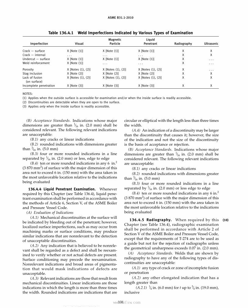
ASME B31.1-2010
Table 136.4.1 Weld Imperfections Indicated by Various Types of Examination
Magnetic LiquidImperfection Visual Particle Penetrant Radiography Ultrasonic
Crack — surface X [Note (1)] X [Note (1)] X [Note (1)] X XCrack — internal . . . . . . . . . X XUndercut — surface X [Note (1)] X [Note (1)] X [Note (1)] X . . .Weld reinforcement X [Note (1)] . . . . . . X . . .
Porosity X [Notes (1), (2)] X [Notes (1), (2)] X [Notes (1), (2)] X . . .Slag inclusion X [Note (2)] X [Note (2)] X [Note (2)] X XLack of fusion X [Notes (1), (2)] X [Notes (1), (2)] X [Notes (1), (2)] X X
(on surface)Incomplete penetration X [Note (3)] X [Note (3)] X [Note (3)] X X
NOTES:(1) Applies when the outside surface is accessible for examination and/or when the inside surface is readily accessible.(2) Discontinuities are detectable when they are open to the surface.(3) Applies only when the inside surface is readily accessible.
(B) Acceptance Standards. Indications whose majordimensions are greater than 1⁄16 in. (2.0 mm) shall beconsidered relevant. The following relevant indicationsare unacceptable:
(B.1) any cracks or linear indications(B.2) rounded indications with dimensions greater
than 3⁄16 in. (5.0 mm)(B.3) four or more rounded indications in a line
separated by 1⁄16 in. (2.0 mm) or less, edge to edge(B.4) ten or more rounded indications in any 6 in.2
(3 870 mm2) of surface with the major dimension of thisarea not to exceed 6 in. (150 mm) with the area taken inthe most unfavorable location relative to the indicationsbeing evaluated
136.4.4 Liquid Penetrant Examination. Wheneverrequired by this Chapter (see Table 136.4), liquid pene-trant examination shall be performed in accordance withthe methods of Article 6, Section V, of the ASME Boilerand Pressure Vessel Code.
(A) Evaluation of Indications(A.1) Mechanical discontinuities at the surface will
be indicated by bleeding out of the penetrant; however,localized surface imperfections, such as may occur frommachining marks or surface conditions, may producesimilar indications that are nonrelevant to the detectionof unacceptable discontinuities.
(A.2) Any indication that is believed to be nonrele-vant shall be regarded as a defect and shall be reexam-ined to verify whether or not actual defects are present.Surface conditioning may precede the reexamination.Nonrelevant indications and broad areas of pigmenta-tion that would mask indications of defects areunacceptable.
(A.3) Relevant indications are those that result frommechanical discontinuities. Linear indications are thoseindications in which the length is more than three timesthe width. Rounded indications are indications that are
104
circular or elliptical with the length less than three timesthe width.
(A.4) An indication of a discontinuity may be largerthan the discontinuity that causes it; however, the sizeof the indication and not the size of the discontinuityis the basis of acceptance or rejection.
(B) Acceptance Standards. Indications whose majordimensions are greater than 1⁄16 in. (2.0 mm) shall beconsidered relevant. The following relevant indicationsare unacceptable:
(B.1) any cracks or linear indications(B.2) rounded indications with dimensions greater
than 3⁄16 in. (5.0 mm)(B.3) four or more rounded indications in a line
separated by 1⁄16 in. (2.0 mm) or less edge to edge(B.4) ten or more rounded indications in any 6 in.2
(3 870 mm2) of surface with the major dimension of thisarea not to exceed 6 in. (150 mm) with the area taken inthe most unfavorable location relative to the indicationsbeing evaluated
136.4.5 Radiography. When required by thisChapter (see Table 136.4), radiographic examinationshall be performed in accordance with Article 2 ofSection V of the ASME Boiler and Pressure Vessel Code,except that the requirements of T-274 are to be used asa guide but not for the rejection of radiographs unlessthe geometrical unsharpness exceeds 0.07 in. (2.0 mm).
(A) Acceptance Standards. Welds that are shown byradiography to have any of the following types of dis-continuities are unacceptable:
(A.1) any type of crack or zone of incomplete fusionor penetration
(A.2) any other elongated indication that has alength greater than
(A.2.1) 1⁄4 in. (6.0 mm) for t up to 3⁄4 in. (19.0 mm),inclusive
(10)
Copyright ASME International Provided by IHS under license with ASME No reproduction or networking permitted without license from IHS
--`,,```````,,```,`,`,,,,`,`,`,`-`-`,,`,,`,`,,`---
标准分享网 www.bzfxw.com 免费下载

ASME B31.1-2010
(A.2.2) 1⁄3t for t from 3⁄4 in. (19.0 mm) to 21⁄4 in.(57.0 mm), incl.
(A.2.3) 3⁄4 in. (19.0 mm) for t over 21⁄4 in. (57.0 mm)where t is the thickness of the thinner portion of the weld
NOTE: t referred to in (A.2.1), (A.2.2), and (A.2.3) above pertainsto the thickness of the weld being examined; if a weld joins twomembers having different thickness at the weld, t is the thinnerof these two thickness.
(A.3) any group of indications in line that have anaggregate length greater than t in a length of 12t, exceptwhere the distance between the successive indicationsexceeds 6L where L is the longest indication in the group
(A.4) porosity in excess of that shown as acceptablein Appendix A-250 of Section I of the ASME Boiler andPressure Vessel Code
(A.5) root concavity when there is an abrupt changein density, as indicated on the radiograph
136.4.6 Ultrasonic Examination. When required bythis Chapter (see Table 136.4), ultrasonic examination(UT) shall be performed in accordance with Article 4 ofSection V of the ASME Boiler and Pressure Vessel Codeand the following additional requirements.
(A) The following criteria shall also be met when per-forming ultrasonic examinations:
(A.1) The equipment used to perform the examina-tion shall be capable of recording the UT data to facilitatethe analysis by a third party and for the repeatabilityof subsequent examinations, should they be required.Where physical obstructions prevent the use of systemscapable of recording the UT data, manual UT may beused with the approval of the Owner.
(A.2) NDE personnel performing and evaluatingUT examinations shall be qualified and certified inaccordance with their employer’s written practice andthe requirements of para. 136.3.2 of this Code. Personnel,procedures, and equipment used to collect and analyzeUT data shall have demonstrated their ability to performan acceptable examination using test blocks approvedby the Owner.
(B) Acceptance Standards. Welds that are shown byultrasonic examination to have discontinuities that pro-duce an indication greater than 20% of the referencelevel shall be investigated to the extent that ultrasonicexamination personnel can determine their shape, iden-tity, and location so that they may evaluate each disconti-nuity for acceptance in accordance with (B.1) and (B.2)below.
(B.1) Discontinuities evaluated as being cracks, lackof fusion, or incomplete penetration are unacceptableregardless of length.
(B.2) Other discontinuities are unacceptable if theindication exceeds the reference level and their lengthexceeds the following:
(B.2.1) 1⁄4 in. (6.0 mm) for t up to 3⁄4 in. (19.0 mm).
105
(B.2.2) 1⁄3t for t from 3⁄4 in. (19.0 mm) to 21⁄4 in.(57.0 mm).
(B.2.3) 3⁄4 in. (19.0 mm) for t over 21⁄4 in. (57.0 mm)where t is the thickness of the weld being examined. Ifthe weld joins two members having different thicknessesat the weld, t is the thinner of these two thicknesses.
137 PRESSURE TESTS
137.1 General Requirements
137.1.1 Subassemblies. When conducted in accor-dance with the requirements of this Code, the pressuretesting of piping systems to ensure leak tightness shallbe acceptable for the determination of any leaks in pip-ing subassemblies.
137.1.2 Temperature of Test Medium. The tempera-ture of the test medium shall be that of the availablesource unless otherwise specified by the Owner. Thetest pressure shall not be applied until the system andthe pressurizing medium are approximately at the sametemperature. When conducting pressure tests at lowmetal temperatures, the possibility of brittle fractureshall be considered.
137.1.3 Personnel Protection. Suitable precautionsin the event of piping system rupture shall be taken toeliminate hazards to personnel in the proximity of linesbeing tested.
137.1.4 Maximum Stress During Test. At no timeduring the pressure test shall any part of the pipingsystem be subjected to a stress greater than that permit-ted by para. 102.3.3(B).
137.1.5 Testing Schedule. Pressure testing shall beperformed following the completion of postweld heattreatment, required by para. 132, nondestructive exami-nations required by Table 136.4, and all other fabrication,assembly and erection activities required to provide thesystem or portions thereof subjected to the pressure testwith pressure retaining capability.
137.2 Preparation for Testing
137.2.1 Exposure of Joints. All joints includingwelds not previously pressure tested shall be left uninsu-lated and exposed for examination during the test. Byprior agreement the complete system or portions thereofsubject to test may be insulated prior to the test periodprovided an extended holding time pressurization ofthe system is performed to check for possible leakagethrough the insulation barrier.
137.2.2 Addition of Temporary Supports. Pipingsystems designed for vapor or gas shall be providedwith additional temporary supports if necessary to sup-port the weight of the test liquid. Such supports shallmeet the requirements for testing and system cleanupprocedures described in para. 122.10.
Copyright ASME International Provided by IHS under license with ASME No reproduction or networking permitted without license from IHS
--`,,```````,,```,`,`,,,,`,`,`,`-`-`,,`,,`,`,,`---

ASME B31.1-2010
137.2.3 Restraint or Isolation of Expansion Joints.Expansion joints shall be provided with temporaryrestraint if required for the additional pressure loadunder test, or they shall be isolated during the systemtest.
137.2.4 Isolation of Equipment and Piping NotSubjected to Pressure Test. Equipment that is not to besubjected to the pressure test shall be either disconnectedfrom the system or isolated by a blank or similar means.Valves may be used for this purpose provided that valveclosure is suitable for the proposed test pressure. Ownershall be aware of the limitations of pressure and temper-ature for each valve subject to test conditions and asfurther described in para. 107.1(C). Isolated equipmentand piping must be vented.
137.2.5 Treatment of Flanged Joints ContainingBlanks. Flanged joints at which blanks are inserted toblank off other equipment during the test need not betested after removal of the blank provided the require-ments of para. 137.7.1 are subsequently performed.
137.2.6 Precautions Against Test MediumExpansion. If a pressure test is to be maintained for aperiod of time during which the test medium in thesystem is subject to thermal expansion, precautions shallbe taken to avoid excessive pressure. A pressure reliefdevice set at 11⁄3 times the test pressure is recommendedduring the pressure test, provided the requirements ofparas. 137.1.4, 137.4.5, and 137.5.5 are not exceeded.
137.3 Requirements for Specific Piping Systems
137.3.1 Boiler External Piping. Boiler external pip-ing [see para. 100.1.2(A)] shall be hydrostatically testedin accordance with PG-99 of Section I of the ASME Boilerand Pressure Vessel Code. The test shall be conductedin the presence of the Authorized Inspector.
137.3.2 Nonboiler External Piping. All nonboilerexternal piping shall be hydrostatically tested in accor-dance with para. 137.4. As an alternative, when specifiedby the owner, the piping may be leak tested in accor-dance with para. 137.5, 137.6, or 137.7. Lines open tothe atmosphere, such as vents or drains downstream ofthe last shutoff valve, need not be tested.
137.4 Hydrostatic Testing
137.4.1 Material. When permitted by the MaterialSpecification, a system hydrostatic test may be per-formed in lieu of the hydrostatic test required by thematerial specifications for material used in the pipingsubassembly or system provided the minimum test pres-sure required for the piping system is met.
137.4.2 Provision of Air Vents at High Points. Ventsshall be provided at all high points of the piping systemin the position in which the test is to be conducted topurge air pockets while the component or system is
106
filling. Venting during the filling of the system may beprovided by the loosening of flanges having a minimumof four bolts or by the use of equipment vents.
137.4.3 Test Medium. Water shall normally be usedas the test medium unless otherwise specified by theOwner. Test water shall be clean and shall be of suchquality as to minimize corrosion of the materials in thepiping system. Further recommended precautions onthe quality of test water used for hydrotesting of austen-itic (300 series) and ferritic (400 series) stainless steelsare contained in Appendix IV, para. IV-3.4.
137.4.4 Check of Test Equipment Before ApplyingPressure. The test equipment shall be examined beforepressure is applied to ensure that it is tightly connected.All low-pressure filling lines and all other items notsubject to the test pressure shall be disconnected or iso-lated by valves or other suitable means.
137.4.5 Required Hydrostatic Test Pressure. Thehydrostatic test pressure at any point in the piping sys-tem shall not be less than 1.5 times the design pressure,but shall not exceed the maximum allowable test pres-sure of any nonisolated components, such as vessels,pumps, or valves, nor shall it exceed the limits imposedby para. 102.3.3(B). The pressure shall be continuouslymaintained for a minimum time of 10 min and may thenbe reduced to the design pressure and held for suchtime as may be necessary to conduct the examinationsfor leakage. Examinations for leakage shall be made ofall joints and connections. The piping system, exclusiveof possible localized instances at pump or valve packing,shall show no visual evidence of weeping or leaking.
137.5 Pneumatic Testing
137.5.1 General. Except for preliminary testing inaccordance with para. 137.5.4, pneumatic testing shallnot be used unless the Owner specifies pneumatic test-ing or permits its use as an alternative. It is recom-mended that pneumatic testing be used only when oneof the following conditions exists:
(A) when piping systems are so designed that theycannot be filled with water
(B) when piping systems are to be used in serviceswhere traces of the testing medium cannot be tolerated
137.5.2 Test Medium. The gas used as the testmedium shall be nonflammable and nontoxic. Sincecompressed gas may be hazardous when used as a test-ing medium, it is recommended that special precautionsfor protection of personnel be observed when a gasunder pressure is used as the test medium.
137.5.3 Check of Test Equipment Before ApplyingPressure. The test equipment shall be examined beforepressure is applied to ensure that it is tightly connected.All items not subjected to the test pressure shall be
Copyright ASME International Provided by IHS under license with ASME No reproduction or networking permitted without license from IHS
--`,,```````,,```,`,`,,,,`,`,`,`-`-`,,`,,`,`,,`---
标准分享网 www.bzfxw.com 免费下载

ASME B31.1-2010
disconnected or isolated by valves or other suitablemeans.
137.5.4 Preliminary Test. A preliminary pneumatictest not to exceed 25 psig [175 kPa (gage)] may beapplied, prior to other methods of leak testing, as ameans of locating major leaks. If used, the preliminarypneumatic test shall be performed in accordance withthe requirements of paras. 137.5.2 and 137.5.3.
137.5.5 Required Pneumatic Test Pressure. Thepneumatic test pressure shall be not less than 1.2 normore than 1.5 times the design pressure of the pipingsystem. The test pressure shall not exceed the maximumallowable test pressure of any nonisolated component,such as vessels, pumps, or valves, in the system. Thepressure in the system shall gradually be increased tonot more than one-half of the test pressure, after whichthe pressure shall be increased in steps of approximatelyone-tenth of the test pressure until the required testpressure has been reached. The pressure shall be contin-uously maintained for a minimum time of 10 min. Itshall then be reduced to the lesser of design pressure or100 psig [700 kPa (gage)] and held for such time as maybe necessary to conduct the examination for leakage.Examination for leakage detected by soap bubble orequivalent method shall be made of all joints and connec-tions. The piping system, exclusive of possible localizedinstances at pump or valve packing, shall show no evi-dence of leaking.
137.6 Mass-Spectrometer and Halide Testing
137.6.1 When specified by the Owner, systemswith conditions of operation and design that requiretesting methods having a greater degree of sensitivitythan can be obtained by a hydrostatic or pneumatictest shall be tested by a method, such as helium mass-spectrometer test or halide test, which has the requiredsensitivity.
137.6.2 When a mass-spectrometer or halide testis performed, it shall be conducted in accordance withthe instructions of the manufacturer of the test equip-ment. In all cases a calibrated reference leak, with a leakrate not greater than the maximum permissible leakagefrom the system, shall be used. The equipment shall becalibrated against the reference leak in such a way thatthe system leakage measured by the equipment can bedetermined to be not greater than the leak rate of thereference leak.
137.7 Initial Service Testing
137.7.1 When specified by the owner, an initialservice test and examination is acceptable when other
107
types of tests are not practical or when leak tightnessis demonstrable due to the nature of the service. Oneexample is piping where shut-off valves are not availablefor isolating a line and where temporary closures areimpractical. Others may be systems where during thecourse of checking out of pumps, compressors, or otherequipment, ample opportunity is afforded for examina-tion for leakage prior to full scale operation. An initialservice test is not applicable to boiler external piping.
137.7.2 When performing an initial service test, thepiping system shall be gradually brought up to normaloperating pressure and continuously held for a mini-mum time of 10 min. Examination for leakage shall bemade of all joints and connections. The piping systemexclusive of possible localized instances at pump orvalve packing shall show no visual evidence of weepingor leaking.
137.8 Retesting After Repair or Additions
137.8.1 Repairs may be made to the pressure partsof boiler external piping after the hydrostatic testrequired by para. 137.3.1, provided the requirements ofPW-54.2 of Section I of the ASME Boiler and PressureVessel Code are met.
137.8.2 Nonpressure parts may be welded to thepressure parts of boiler external piping after the hydro-static test required by para. 137.3.1, provided the require-ments of PW-54.3 of Section I of the ASME Boiler andPressure Vessel Code are met.
137.8.3 If repairs or additions to nonboiler externalpiping are made following a test, the affected pipingshall be retested in accordance with the provisions ofpara. 137.3.2. However, a system need not be retestedafter seal welding or after attachments of lugs, brackets,insulation supports, nameplates, or other nonpressureretaining attachments provided
(A) the attachment fillet weld does not exceed 3⁄8 in.(10.0 mm) thickness or, if a full penetration weld is used,the material attached does not exceed the nominal thick-ness of the pressure retaining member or 1⁄2 in. (12.0 mm),whichever is less
(B) welds shall be preheated as required by para. 131(C) welds shall be examined as required by
Table 136.4(D) seal welds shall be examined for leakage after
system startup
137.8.4 All weld defect repairs shall be made inaccordance with para. 127.4.11.
Copyright ASME International Provided by IHS under license with ASME No reproduction or networking permitted without license from IHS
--`,,```````,,```,`,`,,,,`,`,`,`-`-`,,`,,`,`,,`---

ASME B31.1-2010
Chapter VIIOperation and Maintenance
138 GENERALSafety is the overriding concern in design, operation,
and maintenance of power piping. Managing safe pipingservice begins with the initial project concept and contin-ues throughout the service life of the piping system. TheOperating Company is responsible for the safe operationand maintenance of its power piping.
The Code does not prescribe a detailed set of operatingand maintenance procedures that will encompass allcases. Each Operating Company shall develop operationand maintenance procedures for piping systems deemednecessary to ensure safe facility operations based on theprovisions of this Code, relevant industry experience,the Operating Company’s experience and knowledgeof its facility, and conditions under which the pipingsystems are operated. The additional requirementsdescribed in paras. 139 through 141 apply to coveredpiping systems (CPS).
139 OPERATION AND MAINTENANCEPROCEDURES
For CPS, this shall be accomplished by the issuanceof written operation and maintenance procedures. Theoperation and maintenance procedures established bythe Operating Company for ensuring safe operation ofits CPS may vary, but the following aspects shall becovered:
(A) operation of piping system within design limits(B) documentation of system operating hours and
modes of operation(C) documentation of actual operating temperatures
and pressures(D) documentation of significant system transients or
excursions including thermal hydraulic events (e.g.,steam hammers, liquid slugging)
(E) documentation of modifications, repairs, andreplacements
(F) documentation of maintenance of pipe supportsfor piping operating within the creep regime
(G) documentation of maintenance of piping systemelements such as vents, drains, relief valves, desuper-heaters, and instrumentation necessary for safeoperation
(H) assessment of degradation mechanisms, includ-ing, but not limited to, creep, fatigue, graphitization,corrosion, erosion, and flow accelerated corrosion (FAC)
(I) quality of flow medium (e.g., dissolved oxygen,pH)
108
(J) documentation of the condition assessment (seepara. 140)
(K) other required maintenance
140 CONDITION ASSESSMENT OF CPS
A program shall be established to provide for theassessment and documentation of the condition of allCPS. The documentation shall include a statement as toany actions necessary for continued safe operation. Acondition assessment shall be performed at periodicintervals as determined by an engineering evaluation.
Condition assessments shall be made of CPS based onestablished industry practices. The condition assessmentmay range from a review of previous inspection findingsand operating history since the previous inspection, toa thorough nondestructive examination (NDE) and engi-neering evaluation. The extent of the assessment per-formed shall be established by the Operating Companyor its designee with consideration of the age of the CPS,the previous documented assessment, and anticipatedoperating conditions.
The condition assessment documentation, in a formestablished by the Operating Company, should contain(but not be limited to) as many of the following elementsas available:
(A) system name(B) listing of original material specifications and their
editions(C) design diameters and wall thicknesses(D) design temperature and pressure(E) normal operating temperature and pressure(F) operating hours, both cumulative (from initial
operation) and since last condition assessment(G) actual modes of operation since last condition
assessment (such as the number of hot, warm, and coldstarts)
(H) pipe support hot and cold walk-down readingsand conditions since last condition assessment for pip-ing systems that are operated within the creep regime
(I) modifications and repairs since last conditionassessment
(J) description and list of any dynamic events, includ-ing thermal hydraulic events, since the last conditionassessment
(K) actual pipe wall thickness and outside diametermeasurements taken since the last condition assessmentas appropriate based on service
Copyright ASME International Provided by IHS under license with ASME No reproduction or networking permitted without license from IHS
--`,,```````,,```,`,`,,,,`,`,`,`-`-`,,`,,`,`,,`---标准分享网 www.bzfxw.com 免费下载

ASME B31.1-2010
(L) summary of pipe system inspection findings,including list of areas of concern
(M) recommendations for reinspection interval andscope
Guidance on condition assessment may be found inNonmandatory Appendix V of this Code.
141 CPS RECORDS
CPS records shall be maintained and easily accessiblefor the life of the piping systems and should consist of,but not be limited to
109
(A) procedures required by para. 139(B) condition assessment documentation required by
para. 140(C) original, as-built, and as modified or repaired pip-
ing drawings(D) design and modified or repaired pipe support
drawings for piping operating within the creep regime
Copyright ASME International Provided by IHS under license with ASME No reproduction or networking permitted without license from IHS
--`,,```````,,```,`,`,,,,`,`,`,`-`-`,,`,,`,`,,`---

INTENTIONALLY LEFT BLANK
110
Copyright ASME International Provided by IHS under license with ASME No reproduction or networking permitted without license from IHS
--`,,```````,,```,`,`,,,,`,`,`,`-`-`,,`,,`,`,,`---
标准分享网 www.bzfxw.com 免费下载

ASME B31.1-2010
MANDATORY APPENDICES
MANDATORY APPENDIX A
Begins on next page.
111
Copyright ASME International Provided by IHS under license with ASME No reproduction or networking permitted without license from IHS
--`,,```````,,```,`,`,,,,`,`,`,`-`-`,,`,,`,`,,`---

ASME B31.1-2010
Table A-1 Carbon Steel
Specified SpecifiedMinimum Minimum E
Spec. Nominal P- Tensile, Yield, orNo. Grade Type or Class Composition No. Notes ksi ksi F
Seamless Pipe and Tube
A 53 A S C 1 (2) 48 30 1.00B S C–Mn 1 (2) 60 35 1.00
A 106 A . . . C–Si 1 (2) 48 30 1.00B . . . C–Si 1 (2) 60 35 1.00C . . . C–Si 1 (2) 70 40 1.00
A 179 . . . . . . C 1 (1)(2)(5) (47) 26 1.00
A 192 . . . . . . C–Si 1 (2)(5) (47) 26 1.00
A 210 A-1 . . . C–Si 1 (2) 60 37 1.00C . . . C–Mn–Si 1 (2) 70 40 1.00
A 333 1 . . . C–Mn 1 (1) 55 30 1.006 . . . C–Mn–Si 1 (1) 60 35 1.00
A 369 FPA . . . C–Si 1 (2) 48 30 1.00FPB . . . C–Mn 1 (2) 60 35 1.00
API 5L A . . . C 1 (1)(2)(14) 48 30 1.00B . . . C–Mn 1 (1)(2)(14) 60 35 1.00
Furnace Butt Welded Pipe
A 53 . . . F C 1 (4) 48 30 0.60
API 5L A25 I & II C 1 (1)(4)(14) 45 25 0.60
Electric Resistance Welded Pipe and Tube
A 53 A E C 1 (2) 48 30 0.85B E C–Mn 1 (2) 60 35 0.85
A 135 A . . . C 1 (1)(2) 48 30 0.85B . . . C–Mn 1 (1)(2) 60 35 0.85
A 178 A . . . C 1 (2)(5) (47) 26 0.85C . . . C 1 (2) 60 37 0.85
A 214 . . . . . . C 1 (1)(2)(5) (47) 26 0.85
. . . . . . . . . . . . . . . . . . . . . . . . . . .
A 333 1 . . . C–Mn 1 (1) 55 30 0.856 . . . C–Mn–Si 1 (1) 60 35 0.85
112
Copyright ASME International Provided by IHS under license with ASME No reproduction or networking permitted without license from IHS
--`,,```````,,```,`,`,,,,`,`,`,`-`-`,,`,,`,`,,`---
标准分享网 www.bzfxw.com 免费下载

ASME B31.1-2010
Table A-1 Carbon Steel
Maximum Allowable Stress Values in Tension, ksi, for Metal Temperature, °F, Not Exceeding
−20to Spec.
100 200 300 400 500 600 650 700 750 800 Grade No.
Seamless Pipe and Tube
13.7 13.7 13.7 13.7 13.7 13.7 13.7 12.5 10.7 9.0 A A 5317.1 17.1 17.1 17.1 17.1 17.1 17.1 15.6 13.0 10.8 B
13.7 13.7 13.7 13.7 13.7 13.7 13.7 12.5 10.7 9.0 A A 10617.1 17.1 17.1 17.1 17.1 17.1 17.1 15.6 13.0 10.8 B20.0 20.0 20.0 20.0 20.0 20.0 19.8 18.3 14.8 12.0 C
13.4 13.4 13.4 13.4 13.4 13.3 12.8 12.4 10.7 9.2 . . . A 179
13.4 13.4 13.4 13.4 13.4 13.3 12.8 12.4 10.7 9.0 . . . A 192
17.1 17.1 17.1 17.1 17.1 17.1 17.1 15.6 13.0 10.8 A-1 A 21020.0 20.0 20.0 20.0 20.0 20.0 19.8 18.3 14.8 12.0 C
15.7 15.7 15.7 15.7 15.7 15.3 14.8 . . . . . . . . . 1 A 33317.1 17.1 17.1 17.1 17.1 17.1 17.1 15.6 . . . . . . 6
13.7 13.7 13.7 13.7 13.7 13.7 13.7 12.5 10.7 9.0 FPA A 36917.1 17.1 17.1 17.1 17.1 17.1 17.1 15.6 13.0 10.8 FPB
13.7 13.7 13.7 13.7 13.7 13.7 13.7 12.5 10.7 9.0 A API 5L17.1 17.1 17.1 17.1 17.1 17.1 17.1 15.6 13.0 10.8 B
Furnace Butt Welded Pipe
8.2 8.2 8.2 8.2 8.2 8.2 8.2 7.5 . . . . . . . . . A 53
7.7 7.7 7.7 7.7 . . . . . . . . . . . . . . . . . . A25 API 5L
Electric Resistance Welded Pipe and Tube
11.7 11.7 11.7 11.7 11.7 11.7 11.7 10.6 9.1 7.7 A A 5314.6 14.6 14.6 14.6 14.6 14.6 14.6 13.3 11.1 9.2 B
11.7 11.7 11.7 11.7 11.7 11.7 11.7 10.6 9.1 7.9 A A 13514.6 14.6 14.6 14.6 14.6 14.6 14.6 13.3 11.1 9.2 B
11.4 11.4 11.4 11.4 11.4 11.3 10.9 10.5 9.1 7.7 A A 17814.6 14.6 14.6 14.6 14.6 14.6 14.6 13.3 11.1 9.2 C
11.4 11.4 11.4 11.4 11.4 11.3 10.9 10.5 9.1 7.8 . . . A 214
. . . . . . . . . . . . . . . . . . . . . . . . . . . . . . . . . . . .
13.4 13.4 13.4 13.4 13.4 13.0 12.6 . . . . . . . . . 1 A 33314.6 14.6 14.6 14.6 14.6 14.6 14.6 13.3 . . . . . . 6
113
Copyright ASME International Provided by IHS under license with ASME No reproduction or networking permitted without license from IHS
--`,,```````,,```,`,`,,,,`,`,`,`-`-`,,`,,`,`,,`---

ASME B31.1-2010
Table A-1 Carbon Steel (Cont’d)
Specified SpecifiedMinimum Minimum E
Spec. Nominal P- Tensile, Yield, orNo. Grade Type or Class Composition No. Notes ksi ksi F
Electric Resistance Welded Pipe and Tube (Cont’d)
API 5L A25 I & II C 1 (1)(14) 45 25 0.85A . . . C 1 (1)(2)(14) 48 30 0.85B . . . C–Mn 1 (1)(2)(14) 60 35 0.85
A 587 . . . . . . C 1 (1)(2) 48 30 0.85
Electric Fusion Welded Pipe — Filler Metal Added
A 134 A283A . . . C 1 (1)(7) 45 24 0.80A283B . . . C 1 (1)(7) 50 27 0.80A283C . . . C 1 (1)(7) 55 30 0.80A283D . . . C 1 (1)(7) 60 33 0.80
A 134 A285A . . . C 1 (1)(2)(8) 45 24 0.80A285B . . . C 1 (1)(2)(8) 50 27 0.80A285C . . . C 1 (1)(2)(8) 55 30 0.80
A 139 A . . . C 1 (1)(2)(14) 48 30 0.80B . . . C–Mn 1 (1)(2)(14) 60 35 0.80
API 5L A . . . C 1 (1)(2)(14) 48 30 0.90B . . . C–Mn 1 (1)(2)(14) 60 35 0.90
A 211 A570-30 . . . C 1 (1)(7)(14)(16) 49 30 0.75A570-33 . . . C 1 (1)(7)(14)(16) 52 33 0.75A570-40 . . . C 1 (1)(7)(14)(16) 55 40 0.75
A 671 CA55 10,13 C 1 (1)(2)(15) 55 30 0.90CA55 11,12 C 1 (1)(2)(15) 55 30 1.00CA55 20,23,30,33 C 1 (1)(2) 55 30 0.90CA55 21,22,31,32 C 1 (1)(2) 55 30 1.00
A 671 CB60 10,13 C–Si 1 (1)(2)(15) 60 32 0.90CB60 11,12 C–Si 1 (1)(2)(15) 60 32 1.00CB60 20,23,30,33 C–Si 1 (1)(2) 60 32 0.90CB60 21,22,31,32 C–Si 1 (1)(2) 60 32 1.00
A 671 CB65 10,13 C–Si 1 (1)(2)(15) 65 35 0.90CB65 11,12 C–Si 1 (1)(2)(15) 65 35 1.00CB65 20,23,30,33 C–Si 1 (1)(2) 65 35 0.90CB65 21,22,31,32 C–Si 1 (1)(2) 65 35 1.00
A 671 CB70 10,13 C–Si 1 (1)(2)(15) 70 38 0.90CB70 11,12 C–Si 1 (1)(2)(15) 70 38 1.00CB70 20,23,30,33 C–Si 1 (1)(2) 70 38 0.90CB70 21,22,31,32 C–Si 1 (1)(2) 70 38 1.00
A 671 CC60 10,13 C–Mn–Si 1 (1)(2)(15) 60 32 0.90CC60 11,12 C–Mn–Si 1 (1)(2)(15) 60 32 1.00CC60 20,23,30,33 C–Mn–Si 1 (1)(2) 60 32 0.90CC60 21,22,31,32 C–Mn–Si 1 (1)(2) 60 32 1.00
114
Copyright ASME International Provided by IHS under license with ASME No reproduction or networking permitted without license from IHS
--`,,```````,,```,`,`,,,,`,`,`,`-`-`,,`,,`,`,,`---
标准分享网 www.bzfxw.com 免费下载

ASME B31.1-2010
Table A-1 Carbon Steel (Cont’d)
Maximum Allowable Stress Values in Tension, ksi, for Metal Temperature, °F, Not Exceeding
−20to Spec.
100 200 300 400 500 600 650 700 750 800 Grade No.
Electric Resistance Welded Pipe and Tube (Cont’d)
10.9 10.9 10.9 10.9 . . . . . . . . . . . . . . . . . . A25 API 5L11.7 11.7 11.7 11.7 11.7 11.7 11.7 10.6 9.1 7.7 A14.6 14.6 14.6 14.6 14.6 14.6 14.6 13.3 11.1 9.2 B
11.7 11.7 11.7 11.7 11.7 11.7 11.7 10.6 9.1 7.8 . . . A 587
Electric Fusion Welded Pipe — Filler Metal Added
10.3 10.3 10.3 10.3 10.3 9.8 9.5 . . . . . . . . . A283A A 13411.4 11.4 11.4 11.4 11.4 11.0 10.7 . . . . . . . . . A283B12.6 12.6 12.6 12.6 12.6 12.3 11.9 . . . . . . . . . A283C13.7 13.7 13.7 13.7 13.7 13.5 13.0 . . . . . . . . . A283D
10.3 10.3 10.3 10.3 10.3 9.8 9.5 9.2 8.6 6.6 A285A A 13411.4 11.4 11.4 11.4 11.4 11.0 10.7 10.0 8.8 6.5 A285B12.6 12.6 12.6 12.6 12.6 12.3 11.9 11.5 10.4 8.6 A285C
11.0 11.0 11.0 11.0 11.0 11.0 11.0 10.0 8.6 7.4 A A 13913.7 13.7 13.7 13.7 13.7 13.7 13.7 12.5 10.4 8.6 B
12.3 12.3 12.3 12.3 12.3 12.3 12.3 11.3 9.6 8.3 A API 5L15.4 15.4 15.4 15.4 15.4 15.4 15.4 14.0 11.7 9.7 B
10.5 10.5 . . . . . . . . . . . . . . . . . . . . . . . . A570-30 A 21111.1 11.1 . . . . . . . . . . . . . . . . . . . . . . . . A570-3311.8 11.8 . . . . . . . . . . . . . . . . . . . . . . . . A570-40
14.1 14.1 14.1 14.1 14.1 13.8 13.3 12.9 11.7 9.7 CA55 A 67115.7 15.7 15.7 15.7 15.7 15.3 14.8 14.3 13.0 10.8 CA5514.1 14.1 14.1 14.1 14.1 13.8 13.3 12.9 11.7 9.7 CA5515.7 15.7 15.7 15.7 15.7 15.3 14.8 14.3 13.0 10.8 CA55
15.4 15.4 15.4 15.4 15.4 14.7 14.2 13.7 11.7 9.7 CB60 A 67117.1 17.1 17.1 17.1 17.1 16.4 15.8 15.3 13.0 10.8 CB6015.4 15.4 15.4 15.4 15.4 14.7 14.2 13.7 11.7 9.7 CB6017.1 17.1 17.1 17.1 17.1 16.4 15.8 15.3 13.0 10.8 CB60
16.7 16.7 16.7 16.7 16.7 16.1 15.6 15.0 12.5 10.3 CB65 A 67118.6 18.6 18.6 18.6 18.6 17.9 17.3 16.7 13.9 11.4 CB6516.7 16.7 16.7 16.7 16.7 16.1 15.6 15.0 12.5 10.3 CB6518.6 18.6 18.6 18.6 18.6 17.9 17.3 16.7 13.9 11.4 CB65
18.0 18.0 18.0 18.0 18.0 17.5 16.9 16.3 13.3 10.8 CB70 A 67120.0 20.0 20.0 20.0 20.0 19.4 18.8 18.1 14.8 12.0 CB7018.0 18.0 18.0 18.0 18.0 17.5 16.9 16.3 13.3 10.8 CB7020.0 20.0 20.0 20.0 20.0 19.4 18.8 18.1 14.8 12.0 CB70
15.4 15.4 15.4 15.4 15.4 14.7 14.2 13.7 11.7 9.7 CC60 A 67117.1 17.1 17.1 17.1 17.1 16.4 15.8 15.3 13.0 10.8 CC6015.4 15.4 15.4 15.4 15.4 14.7 14.2 13.7 11.7 9.7 CC6017.1 17.1 17.1 17.1 17.1 16.4 15.8 15.3 13.0 10.8 CC60
115
Copyright ASME International Provided by IHS under license with ASME No reproduction or networking permitted without license from IHS
--`,,```````,,```,`,`,,,,`,`,`,`-`-`,,`,,`,`,,`---

ASME B31.1-2010
Table A-1 Carbon Steel (Cont’d)
Specified SpecifiedMinimum Minimum E
Spec. Nominal P- Tensile, Yield, orNo. Grade Type or Class Composition No. Notes ksi ksi F
Electric Fusion Welded Pipe — Filler Metal Added (Cont’d)
A 671 CC65 10,13 C–Mn–Si 1 (1)(2)(15) 65 35 0.90CC65 11,12 C–Mn–Si 1 (1)(2)(15) 65 35 1.00CC65 20,23,30,33 C–Mn–Si 1 (1)(2) 65 35 0.90CC65 21,22,31,32 C–Mn–Si 1 (1)(2) 65 35 1.00
A 671 CC70 10,13 C–Mn–Si 1 (1)(2)(15) 70 38 0.90CC70 11,12 C–Mn–Si 1 (1)(2)(15) 70 38 1.00CC70 20,23,30,33 C–Mn–Si 1 (1)(2) 70 38 0.90CC70 21,22,31,32 C–Mn–Si 1 (1)(2) 70 38 1.00
A 671 CK75 10,13 C–Mn–Si 1 (1)(2)(15) 75 42 0.90CK75 11,12 C–Mn–Si 1 (1)(2)(15) 75 42 1.00CK75 20,23,30,33 C–Mn–Si 1 (1)(2) 75 40 0.90CK75 21,22,31,32 C–Mn–Si 1 (1)(2) 75 40 1.00
A 671 CD70 10,13 C–Mn–Si 1 (1)(2)(15) 70 50 0.90CD70 11,12 C–Mn–Si 1 (1)(2)(15) 70 50 1.00CD70 20,23,30,33 C–Mn–Si 1 (1)(3) 70 50 0.90CD70 21,22,31,32 C–Mn–Si 1 (1)(3) 70 50 1.00
A 671 CD80 10,13 C–Mn–Si 1 (1)(15) 80 60 0.90CD80 11,12 C–Mn–Si 1 (1)(15) 80 60 1.00CD80 20,23 C–Mn–Si 1 (1)(3) 80 60 0.90CD80 21,22 C–Mn–Si 1 (1)(3) 80 60 1.00
A 672 A45 10,13 C 1 (1)(2)(15) 45 24 0.90A45 11,12 C 1 (1)(2)(15) 45 24 1.00A45 20,23,30,33 C 1 (1)(2) 45 24 0.90A45 21,22,31,32 C 1 (1)(2) 45 24 1.00
A 672 A50 10,13 C 1 (1)(2)(15) 50 27 0.90A50 11,12 C 1 (1)(2)(15) 50 27 1.00A50 20,23,30,33 C 1 (1)(2) 50 27 0.90A50 21,22,31,32 C 1 (1)(2) 50 27 1.00
A 672 A55 10,13 C 1 (1)(2)(15) 55 30 0.90A55 11,12 C 1 (1)(2)(15) 55 30 1.00A55 20,23,30,33 C 1 (1)(2) 55 30 0.90A55 21,22,31,32 C 1 (1)(2) 55 30 1.00
A 672 B55 10,13 C 1 (1)(2)(15) 55 30 0.90B55 11,12 C 1 (1)(2)(15) 55 30 1.00B55 20,23,30,33 C 1 (1)(2) 55 30 0.90B55 21,22,31,32 C 1 (1)(2) 55 30 1.00
A 672 B60 10,13 C 1 (1)(2)(15) 60 32 0.90B60 11,12 C 1 (1)(2)(15) 60 32 1.00B60 20,23,30,33 C 1 (1)(2) 60 32 0.90B60 21,22,31,32 C 1 (1)(2) 60 32 1.00
116
Copyright ASME International Provided by IHS under license with ASME No reproduction or networking permitted without license from IHS
--`,,```````,,```,`,`,,,,`,`,`,`-`-`,,`,,`,`,,`---
标准分享网 www.bzfxw.com 免费下载
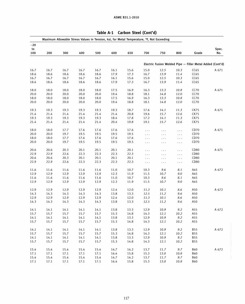
ASME B31.1-2010
Table A-1 Carbon Steel (Cont’d)
Maximum Allowable Stress Values in Tension, ksi, for Metal Temperature, °F, Not Exceeding
−20to Spec.
100 200 300 400 500 600 650 700 750 800 Grade No.
Electric Fusion Welded Pipe — Filler Metal Added (Cont’d)
16.7 16.7 16.7 16.7 16.7 16.1 15.6 15.0 12.5 10.3 CC65 A 67118.6 18.6 18.6 18.6 18.6 17.9 17.3 16.7 13.9 11.4 CC6516.7 16.7 16.7 16.7 16.7 16.1 15.6 15.0 12.5 10.3 CC6518.6 18.6 18.6 18.6 18.6 17.9 17.3 16.7 13.9 11.4 CC65
18.0 18.0 18.0 18.0 18.0 17.5 16.9 16.3 13.3 10.8 CC70 A 67120.0 20.0 20.0 20.0 20.0 19.4 18.8 18.1 14.8 12.0 CC7018.0 18.0 18.0 18.0 18.0 17.5 16.9 16.3 13.3 10.8 CC7020.0 20.0 20.0 20.0 20.0 19.4 18.8 18.1 14.8 12.0 CC70
19.3 19.3 19.3 19.3 19.3 19.3 18.7 17.6 14.1 11.3 CK75 A 67121.4 21.4 21.4 21.4 21.4 21.4 20.8 19.6 15.7 12.6 CK7519.3 19.3 19.3 19.3 19.3 18.4 17.8 17.2 14.1 11.3 CK7521.4 21.4 21.4 21.4 21.4 20.4 19.8 19.1 15.7 12.6 CK75
18.0 18.0 17.7 17.6 17.6 17.6 17.6 . . . . . . . . . CD70 A 67120.0 20.0 19.7 19.5 19.5 19.5 19.5 . . . . . . . . . CD7018.0 18.0 17.7 17.6 17.6 17.6 17.6 . . . . . . . . . CD7020.0 20.0 19.7 19.5 19.5 19.5 19.5 . . . . . . . . . CD70
20.6 20.6 20.3 20.1 20.1 20.1 20.1 . . . . . . . . . CD80 A 67122.9 22.9 22.6 22.3 22.3 22.3 22.3 . . . . . . . . . CD8020.6 20.6 20.3 20.1 20.1 20.1 20.1 . . . . . . . . . CD8022.9 22.9 22.6 22.3 22.3 22.3 22.3 . . . . . . . . . CD80
11.6 11.6 11.6 11.6 11.6 11.0 10.7 10.3 9.6 8.1 A45 A 67212.9 12.9 12.9 12.9 12.9 12.3 11.9 11.5 10.7 9.0 A4511.6 11.6 11.6 11.6 11.6 11.0 10.7 10.3 9.6 8.1 A4512.9 12.9 12.9 12.9 12.9 12.3 11.9 11.5 10.7 9.0 A45
12.9 12.9 12.9 12.9 12.9 12.4 12.0 11.3 10.1 8.6 A50 A 67214.3 14.3 14.3 14.3 14.3 13.8 13.3 12.5 11.2 9.6 A5012.9 12.9 12.9 12.9 12.9 12.4 12.0 11.3 10.1 8.6 A5014.3 14.3 14.3 14.3 14.3 13.8 13.3 12.5 11.2 9.6 A50
14.1 14.1 14.1 14.1 14.1 13.8 13.3 12.9 10.9 9.2 A55 A 67215.7 15.7 15.7 15.7 15.7 15.3 14.8 14.3 12.1 10.2 A5514.1 14.1 14.1 14.1 14.1 13.8 13.3 12.9 10.9 9.2 A5515.7 15.7 15.7 15.7 15.7 15.3 14.8 14.3 12.1 10.2 A55
14.1 14.1 14.1 14.1 14.1 13.8 13.3 12.9 10.9 9.2 B55 A 67215.7 15.7 15.7 15.7 15.7 15.3 14.8 14.3 12.1 10.2 B5514.1 14.1 14.1 14.1 14.1 13.8 13.3 12.9 10.9 9.2 B5515.7 15.7 15.7 15.7 15.7 15.3 14.8 14.3 12.1 10.2 B55
15.4 15.4 15.4 15.4 15.4 14.7 14.2 13.7 11.7 9.7 B60 A 67217.1 17.1 17.1 17.1 17.1 16.4 15.8 15.3 13.0 10.8 B6015.4 15.4 15.4 15.4 15.4 14.7 14.2 13.7 11.7 9.7 B6017.1 17.1 17.1 17.1 17.1 16.4 15.8 15.3 13.0 10.8 B60
117
Copyright ASME International Provided by IHS under license with ASME No reproduction or networking permitted without license from IHS
--`,,```````,,```,`,`,,,,`,`,`,`-`-`,,`,,`,`,,`---

ASME B31.1-2010
Table A-1 Carbon Steel (Cont’d)
Specified SpecifiedMinimum Minimum E
Spec. Nominal P- Tensile, Yield, orNo. Grade Type or Class Composition No. Notes ksi ksi F
Electric Fusion Welded Pipe — Filler Metal Added (Cont’d)
A 672 B65 10,13 C 1 (1)(2)(15) 65 35 0.90B65 11,12 C 1 (1)(2)(15) 65 35 1.00B65 20,23,30,33 C 1 (1)(2) 65 35 0.90B65 21,22,31,32 C 1 (1)(2) 65 35 1.00
A 672 B70 10,13 C 1 (1)(2)(15) 70 38 0.90B70 11,12 C 1 (1)(2)(15) 70 38 1.00B70 20,23,30,33 C 1 (1)(2) 70 38 0.90B70 21,22,31,32 C 1 (1)(2) 70 38 1.00
A 672 C55 10,13 C 1 (1)(2)(15) 55 30 0.90C55 11,12 C 1 (1)(2)(15) 55 30 1.00C55 20,23,30,33 C 1 (1)(2) 55 30 0.90C55 21,22,31,32 C 1 (1)(2) 55 30 1.00
A 672 C60 10,13 C 1 (1)(2)(15) 60 32 0.90C60 11,12 C 1 (1)(2)(15) 60 32 1.00C60 20,23,30,33 C 1 (1)(2) 60 32 0.90C60 21,22,31,32 C 1 (1)(2) 60 32 1.00
A 672 C65 10,13 C 1 (1)(2)(15) 65 35 0.90C65 11,12 C 1 (1)(2)(15) 65 35 1.00C65 20,23,30,33 C 1 (1)(2) 65 35 0.90C65 21,22,31,32 C 1 (1)(2) 65 35 1.00
A 672 C70 10,13 C 1 (1)(2)(15) 70 38 0.90C70 11,12 C 1 (1)(2)(15) 70 38 1.00C70 20,23,30,33 C 1 (1)(2) 70 38 0.90C70 21,22,31,32 C 1 (1)(2) 70 38 1.00
A 672 D70 10,13 C–Mn–Si 1 (1)(15) 70 50 0.90D70 11,12 C–Mn–Si 1 (1)(15) 70 50 1.00D70 20,23,30,33 C–Mn–Si 1 (1)(3) 70 50 0.90D70 21,22,31,32 C–Mn–Si 1 (1)(3) 70 50 1.00
A 672 D80 10,13 C–Mn–Si 1 (1)(15) 80 60 0.90D80 11,12 C–Mn–Si 1 (1)(15) 80 60 1.00D80 20,23 C–Mn–Si 1 (1)(3) 80 60 0.90D80 21,22 C–Mn–Si 1 (1)(3) 80 60 1.00
A 672 N75 10,13 C–Mn–Si 1 (1)(2)(15) 75 42 0.90N75 11,12 C–Mn–Si 1 (1)(2)(15) 75 42 1.00N75 20,23,30,33 C–Mn–Si 1 (1)(2) 75 40 0.90N75 21,22,31,32 C–Mn–Si 1 (1)(2) 75 40 1.00
A 691 CMSH-70 10,13 C–Mn–Si 1 (1)(15) 70 50 0.90CMSH-70 11,12 C–Mn–Si 1 (1)(15) 70 50 1.00CMSH-70 20,23,30,33 C–Mn–Si 1 (1)(3) 70 50 0.90CMSH-70 21,22,31,32 C–Mn–Si 1 (1)(3) 70 50 1.00
118
Copyright ASME International Provided by IHS under license with ASME No reproduction or networking permitted without license from IHS
--`,,```````,,```,`,`,,,,`,`,`,`-`-`,,`,,`,`,,`---
标准分享网 www.bzfxw.com 免费下载

ASME B31.1-2010
Table A-1 Carbon Steel (Cont’d)
Maximum Allowable Stress Values in Tension, ksi, for Metal Temperature, °F, Not Exceeding
−20to Spec.
100 200 300 400 500 600 650 700 750 800 Grade No.
Electric Fusion Welded Pipe — Filler Metal Added (Cont’d)
16.7 16.7 16.7 16.7 16.7 16.1 15.6 15.0 12.5 10.3 B65 A 67218.6 18.6 18.6 18.6 18.6 17.9 17.3 16.7 13.9 11.4 B6516.7 16.7 16.7 16.7 16.7 16.1 15.6 15.0 12.5 10.3 B6518.6 18.6 18.6 18.6 18.6 17.9 17.3 16.7 13.9 11.4 B65
18.0 18.0 18.0 18.0 18.0 17.5 16.9 16.3 13.3 10.8 B70 A 67220.0 20.0 20.0 20.0 20.0 19.4 18.8 18.1 14.8 12.0 B7018.0 18.0 18.0 18.0 18.0 17.5 16.9 16.3 13.3 10.8 B7020.0 20.0 20.0 20.0 20.0 19.4 18.8 18.1 14.8 12.0 B70
14.1 14.1 14.1 14.1 14.1 13.8 13.3 12.9 10.9 9.2 C55 A 67215.7 15.7 15.7 15.7 15.7 15.3 14.8 14.3 12.1 10.2 C5514.1 14.1 14.1 14.1 14.1 13.8 13.3 12.9 10.9 9.2 C5515.7 15.7 15.7 15.7 15.7 15.3 14.8 14.3 12.1 10.2 C55
15.4 15.4 15.4 15.4 15.4 14.7 14.2 13.7 11.7 9.7 C60 A 67217.1 17.1 17.1 17.1 17.1 16.4 15.8 15.3 13.0 10.8 C6015.4 15.4 15.4 15.4 15.4 14.7 14.2 13.7 11.7 9.7 C6017.1 17.1 17.1 17.1 17.1 16.4 15.8 15.3 13.0 10.8 C60
16.7 16.7 16.7 16.7 16.7 16.1 15.6 15.0 12.5 10.3 C65 A 67218.6 18.6 18.6 18.6 18.6 17.9 17.3 16.7 13.9 11.4 C6516.7 16.7 16.7 16.7 16.7 16.1 15.6 15.0 12.5 10.3 C6518.6 18.6 18.6 18.6 18.6 17.9 17.3 16.7 13.9 11.4 C65
18.0 18.0 18.0 18.0 18.0 17.5 16.9 16.3 13.3 10.8 C70 A 67220.0 20.0 20.0 20.0 20.0 19.4 18.8 18.1 14.8 12.0 C7018.0 18.0 18.0 18.0 18.0 17.5 16.9 16.3 13.3 10.8 C7020.0 20.0 20.0 20.0 20.0 19.4 18.8 18.1 14.8 12.0 C70
18.0 18.0 17.7 17.6 17.6 17.6 17.6 . . . . . . . . . D70 A 67220.0 20.0 19.7 19.5 19.5 19.5 19.5 . . . . . . . . . D7018.0 18.0 17.7 17.6 17.6 17.6 17.6 . . . . . . . . . D7020.0 20.0 19.7 19.5 19.5 19.5 19.5 . . . . . . . . . D70
20.6 20.6 20.3 20.1 20.1 20.1 20.1 . . . . . . . . . D80 A 67222.9 22.9 22.6 22.3 22.3 22.3 22.3 . . . . . . . . . D8020.6 20.6 20.3 20.1 20.1 20.1 20.1 . . . . . . . . . D8022.9 22.9 22.6 22.3 22.3 22.3 22.3 . . . . . . . . . D80
19.3 19.3 19.3 19.3 19.3 18.4 17.8 17.2 14.1 11.3 N75 A 67221.4 21.4 21.4 21.4 21.4 20.4 19.8 19.1 15.7 12.6 N7519.3 19.3 19.3 19.3 19.3 18.4 17.8 17.2 14.1 11.3 N7521.4 21.4 21.4 21.4 21.4 20.4 19.8 19.1 15.7 12.6 N75
18.0 18.0 17.7 17.6 17.6 17.6 17.6 . . . . . . . . . CMSH-70 A 69120.0 20.0 19.7 19.5 19.5 19.5 19.5 . . . . . . . . . CMSH-7018.0 18.0 17.7 17.6 17.6 17.6 17.6 . . . . . . . . . CMSH-7020.0 20.0 19.7 19.5 19.5 19.5 19.5 . . . . . . . . . CMSH-70
119
Copyright ASME International Provided by IHS under license with ASME No reproduction or networking permitted without license from IHS
--`,,```````,,```,`,`,,,,`,`,`,`-`-`,,`,,`,`,,`---

ASME B31.1-2010
Table A-1 Carbon Steel (Cont’d)
Specified SpecifiedMinimum Minimum E
Spec. Nominal P- Tensile, Yield, orNo. Grade Type or Class Composition No. Notes ksi ksi F
Electric Fusion Welded Pipe — Filler Metal Added (Cont’d)
A 691 CMSH-80 10,13 C–Mn–Si 1 (1)(15) 80 60 0.90CMSH-80 11,12 C–Mn–Si 1 (1)(15) 80 60 1.00CMSH-80 20,23 C–Mn–Si 1 (1)(3) 80 60 0.90CMSH-80 21,22 C–Mn–Si 1 (1)(3) 80 60 1.00
A 691 CMS-75 10,13 C–Mn–Si 1 (1)(2)(15) 75 42 0.90CMS-75 11,12 C–Mn–Si 1 (1)(2)(15) 75 42 1.00CMS-75 20,23,30,33 C–Mn–Si 1 (1)(2) 75 40 0.90CMS-75 21,22,31,32 C–Mn–Si 1 (1)(2) 75 40 1.00
Copper Brazed Tubing
A 254 . . . . . . C . . . (1)(9)(10) 42 25 1.00
Plate
A 36 . . . . . . C–Mn–Si 1 (1)(7)(21) 58 36 0.92
A 283 A . . . C 1 (1)(7) 45 24 0.92B . . . C 1 (1)(7) 50 27 0.92C . . . C 1 (1)(7) 55 30 0.92D . . . C 1 (1)(7) 60 33 0.92
A 285 A . . . C 1 (2) 45 24 1.00B . . . C 1 (2) 50 27 1.00C . . . C 1 (2) 55 30 1.00
A 299 . . . . . . C–Mn–Si 1 (2)(23) 75 40 1.00. . . . . . C–Mn–Si 1 (2)(22) 75 42 1.00
A 515 60 . . . C–Si 1 (2) 60 32 1.0065 . . . C–Si 1 (2) 65 35 1.0070 . . . C–Si 1 (2) 70 38 1.00
A 516 55 . . . C–Si 1 (2) 55 30 1.0060 . . . C–Mn–Si 1 (2) 60 32 1.0065 . . . C–Mn–Si 1 (2) 65 35 1.0070 . . . C–Mn–Si 1 (2) 70 38 1.00
Forgings
A 105 . . . . . . C–Si 1 (2) 70 36 1.00
A 181 . . . 60 C–Si 1 (2) 60 30 1.00. . . 70 C–Si 1 (2) 70 36 1.00
120
Copyright ASME International Provided by IHS under license with ASME No reproduction or networking permitted without license from IHS
--`,,```````,,```,`,`,,,,`,`,`,`-`-`,,`,,`,`,,`---
标准分享网 www.bzfxw.com 免费下载

ASME B31.1-2010
Table A-1 Carbon Steel (Cont’d)
Maximum Allowable Stress Values in Tension, ksi, for Metal Temperature, °F, Not Exceeding
−20to Spec.
100 200 300 400 500 600 650 700 750 800 Grade No.
Electric Fusion Welded Pipe — Filler Metal Added (Cont’d)
20.6 20.6 20.3 20.1 20.1 20.1 20.1 . . . . . . . . . CMSH-80 A 69122.9 22.9 22.6 22.3 22.3 22.3 22.3 . . . . . . . . . CMSH-8020.6 20.6 20.3 20.1 20.1 20.1 20.1 . . . . . . . . . CMSH-8022.9 22.9 22.6 22.3 22.3 22.3 22.3 . . . . . . . . . CMSH-80
19.3 19.3 19.3 19.3 19.3 18.4 17.8 17.2 14.1 11.3 CMS-75 A 69121.4 21.4 21.4 21.4 21.4 20.4 19.8 19.1 15.7 12.6 CMS-7519.3 19.3 19.3 19.3 19.3 18.4 17.8 17.2 14.1 11.3 CMS-7521.4 21.4 21.4 21.4 21.4 20.4 19.8 19.1 15.7 12.6 CMS-75
Copper Brazed Tubing
6.0 5.5 4.8 3.0 . . . . . . . . . . . . . . . . . . . . . A 254
Plate
15.2 15.2 15.2 15.2 15.2 15.2 15.2 . . . . . . . . . . . . A 36
11.8 11.8 11.8 11.8 11.8 11.3 10.9 . . . . . . . . . A A 28313.1 13.1 13.1 13.1 13.1 12.7 12.3 . . . . . . . . . B14.5 14.5 14.5 14.5 14.5 14.1 13.6 . . . . . . . . . C15.8 15.8 15.8 15.8 15.8 15.5 15.0 . . . . . . . . . D
12.9 12.9 12.9 12.9 12.9 12.3 11.9 11.5 10.7 8.3 A A 28514.3 14.3 14.3 14.3 14.3 13.8 13.3 12.5 11.0 9.4 B15.7 15.7 15.7 15.7 15.7 15.3 14.8 14.3 13.0 10.8 C
21.4 21.4 21.4 21.4 21.4 20.4 19.8 19.1 15.7 12.6 . . . A 29921.4 21.4 21.4 21.4 21.4 21.4 20.8 19.6 15.7 12.6 . . .
17.1 17.1 17.1 17.1 17.1 16.4 15.8 15.3 13.0 10.8 60 A 51518.6 18.6 18.6 18.6 18.6 17.9 17.3 16.7 13.9 11.4 6520.0 20.0 20.0 20.0 20.0 19.4 18.8 18.1 14.8 12.6 70
15.7 15.7 15.7 15.7 15.7 15.3 14.8 14.3 13.0 10.8 55 A 51617.1 17.1 17.1 17.1 17.1 16.4 15.8 15.3 13.0 10.8 6018.6 18.6 18.6 18.6 18.6 17.9 17.3 16.7 13.9 11.4 6520.0 20.0 20.0 20.0 20.0 19.4 18.8 18.1 14.8 12.0 70
Forgings
20.0 20.0 20.0 20.0 19.6 18.4 17.8 17.2 14.8 12.0 . . . A 105
17.1 17.1 17.1 17.1 16.3 15.3 14.8 14.3 13.0 10.8 . . . A 18120.0 20.0 20.0 20.0 19.6 18.4 17.8 17.2 14.8 12.0 . . .
121
Copyright ASME International Provided by IHS under license with ASME No reproduction or networking permitted without license from IHS
--`,,```````,,```,`,`,,,,`,`,`,`-`-`,,`,,`,`,,`---
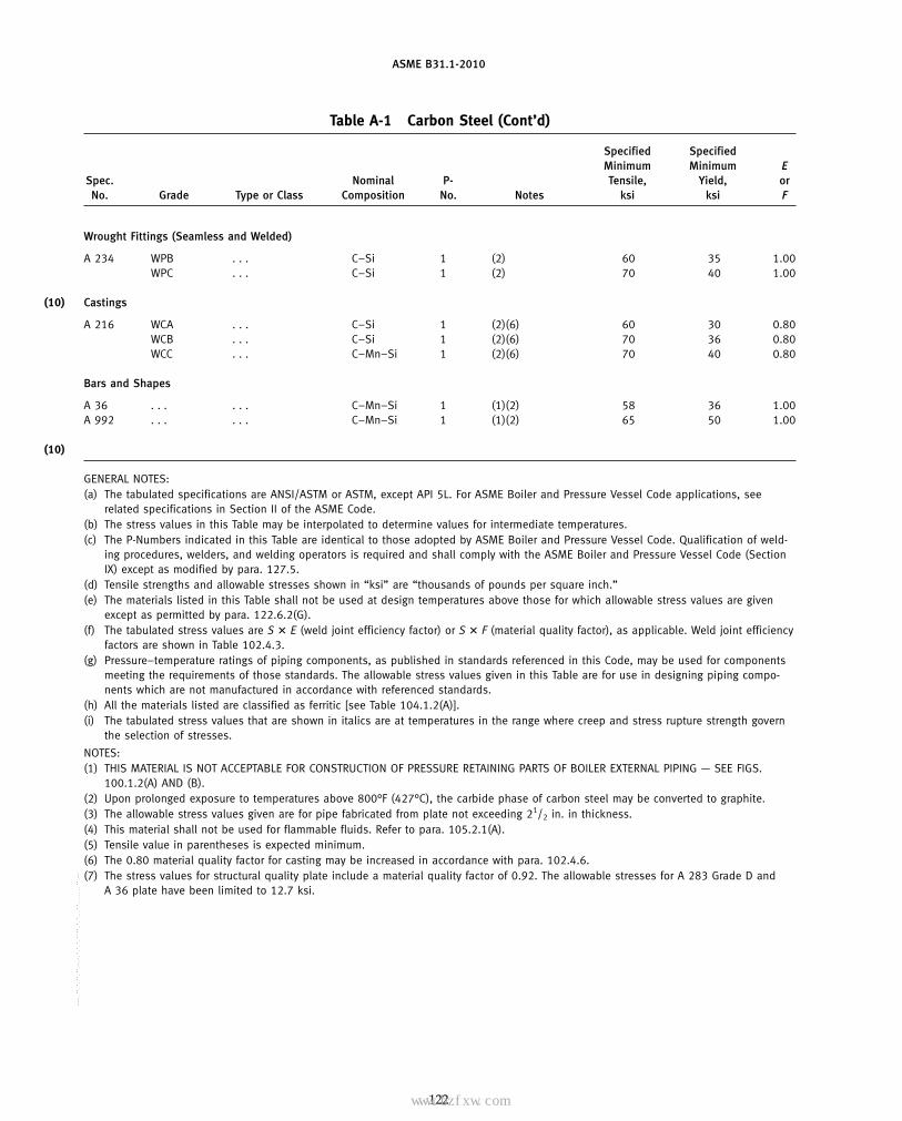
ASME B31.1-2010
Table A-1 Carbon Steel (Cont’d)
Specified SpecifiedMinimum Minimum E
Spec. Nominal P- Tensile, Yield, orNo. Grade Type or Class Composition No. Notes ksi ksi F
Wrought Fittings (Seamless and Welded)
A 234 WPB . . . C–Si 1 (2) 60 35 1.00WPC . . . C–Si 1 (2) 70 40 1.00
(10) Castings
A 216 WCA . . . C–Si 1 (2)(6) 60 30 0.80WCB . . . C–Si 1 (2)(6) 70 36 0.80WCC . . . C–Mn–Si 1 (2)(6) 70 40 0.80
Bars and Shapes
A 36 . . . . . . C–Mn–Si 1 (1)(2) 58 36 1.00A 992 . . . . . . C–Mn–Si 1 (1)(2) 65 50 1.00
(10)
GENERAL NOTES:(a) The tabulated specifications are ANSI/ASTM or ASTM, except API 5L. For ASME Boiler and Pressure Vessel Code applications, see
related specifications in Section II of the ASME Code.(b) The stress values in this Table may be interpolated to determine values for intermediate temperatures.(c) The P-Numbers indicated in this Table are identical to those adopted by ASME Boiler and Pressure Vessel Code. Qualification of weld-
ing procedures, welders, and welding operators is required and shall comply with the ASME Boiler and Pressure Vessel Code (SectionIX) except as modified by para. 127.5.
(d) Tensile strengths and allowable stresses shown in “ksi” are “thousands of pounds per square inch.”(e) The materials listed in this Table shall not be used at design temperatures above those for which allowable stress values are given
except as permitted by para. 122.6.2(G).(f) The tabulated stress values are S � E (weld joint efficiency factor) or S � F (material quality factor), as applicable. Weld joint efficiency
factors are shown in Table 102.4.3.(g) Pressure–temperature ratings of piping components, as published in standards referenced in this Code, may be used for components
meeting the requirements of those standards. The allowable stress values given in this Table are for use in designing piping compo-nents which are not manufactured in accordance with referenced standards.
(h) All the materials listed are classified as ferritic [see Table 104.1.2(A)].(i) The tabulated stress values that are shown in italics are at temperatures in the range where creep and stress rupture strength govern
the selection of stresses.
NOTES:(1) THIS MATERIAL IS NOT ACCEPTABLE FOR CONSTRUCTION OF PRESSURE RETAINING PARTS OF BOILER EXTERNAL PIPING — SEE FIGS.
100.1.2(A) AND (B).(2) Upon prolonged exposure to temperatures above 800°F (427°C), the carbide phase of carbon steel may be converted to graphite.(3) The allowable stress values given are for pipe fabricated from plate not exceeding 21/2 in. in thickness.(4) This material shall not be used for flammable fluids. Refer to para. 105.2.1(A).(5) Tensile value in parentheses is expected minimum.(6) The 0.80 material quality factor for casting may be increased in accordance with para. 102.4.6.(7) The stress values for structural quality plate include a material quality factor of 0.92. The allowable stresses for A 283 Grade D and
A 36 plate have been limited to 12.7 ksi.
122
Copyright ASME International Provided by IHS under license with ASME No reproduction or networking permitted without license from IHS
--`,,```````,,```,`,`,,,,`,`,`,`-`-`,,`,,`,`,,`---
标准分享网 www.bzfxw.com 免费下载

ASME B31.1-2010
Table A-1 Carbon Steel (Cont’d)
Maximum Allowable Stress Values in Tension, ksi, for Metal Temperature, °F, Not Exceeding
−20to Spec.
100 200 300 400 500 600 650 700 750 800 Grade No.
Wrought Fittings (Seamless and Welded)
17.1 17.1 17.1 17.1 17.1 17.1 17.1 15.6 13.0 10.8 WPB A 23420.0 20.0 20.0 20.0 20.0 20.0 19.8 18.3 14.8 12.0 WPC
(10)Castings
13.7 13.7 13.7 13.7 13.0 12.2 11.8 11.4 10.4 8.6 WCA A 21616.0 16.0 16.0 16.0 15.7 14.7 14.2 13.8 11.8 9.6 WCB16.0 16.0 16.0 16.0 16.0 16.0 15.8 14.6 11.8 9.6 WCC
Bars and Shapes
16.6 16.6 16.6 16.6 16.6 16.6 16.6 15.6 13.0 10.8 . . . A 3618.6 18.6 18.6 18.6 18.6 18.6 18.6 16.9 13.9 11.4 . . . A 992
(10)
(10) NOTES (Cont’d):(8) These stress values are permitted only if killed or semikilled steels are used.(9) A 254 is copper brazed (not welded) steel pipe.(10) For saturated steam at 250 psi (406°F), the values given for 400°F may be used.(11) DELETED.(12) DELETED.(13) DELETED.(14) This material is not listed in the ASME Boiler and Pressure Vessel Code, Section IX. However, weld procedures shall be qualified in
accordance with the P-Number shown. See para. 127.5.1.(15) This material shall not be used in nominal wall thicknesses exceeding 3⁄4 in.(16) These allowable stress values are for pipe made using a butt-welded joint process. Pipe made by other processes shall not be used.(17) DELETED.(18) DELETED.(19) DELETED.(20) DELETED.(21) The allowable stress values listed in MSS SP-58 for this material may be used for pipe supporting elements designed in accordance
with MSS SP-58.(22) These values apply to material less than or equal to 1 in. thick.(23) These values apply to material greater than 1 in. thick.
123
Copyright ASME International Provided by IHS under license with ASME No reproduction or networking permitted without license from IHS
--`,,```````,,```,`,`,,,,`,`,`,`-`-`,,`,,`,`,,`---
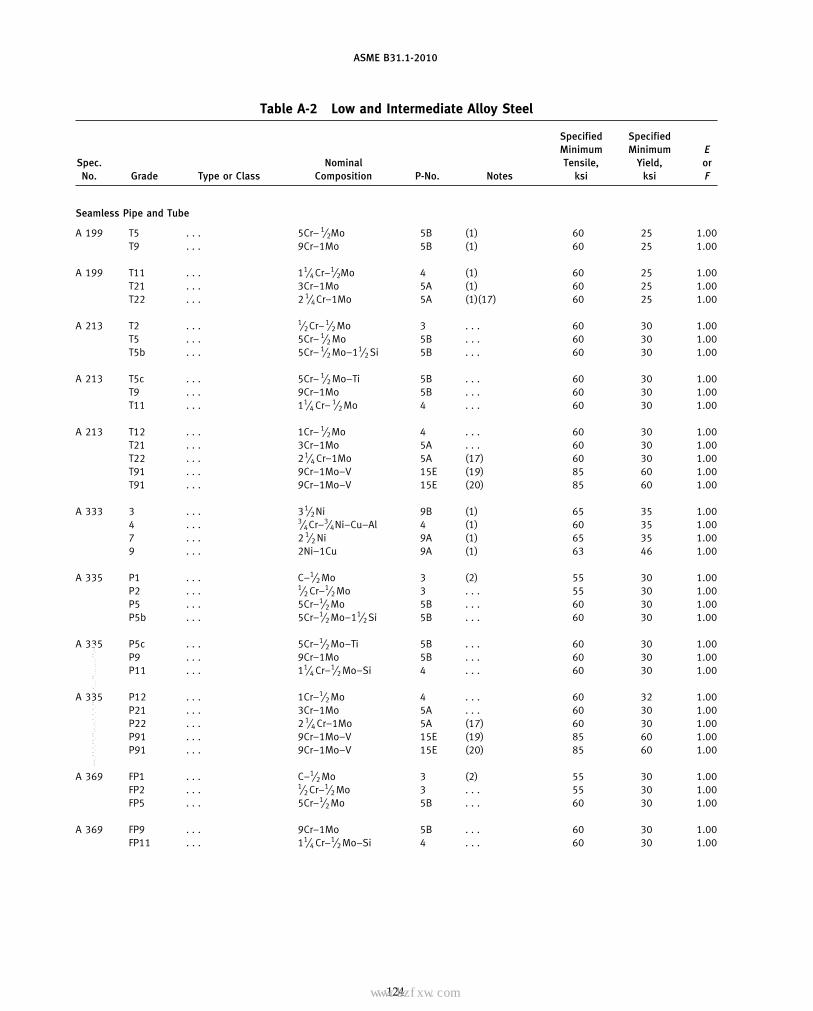
ASME B31.1-2010
Table A-2 Low and Intermediate Alloy Steel
Specified SpecifiedMinimum Minimum E
Spec. Nominal Tensile, Yield, orNo. Grade Type or Class Composition P-No. Notes ksi ksi F
Seamless Pipe and Tube
A 199 T5 . . . 5Cr– 1⁄2Mo 5B (1) 60 25 1.00T9 . . . 9Cr–1Mo 5B (1) 60 25 1.00
A 199 T11 . . . 11⁄4Cr–1⁄2Mo 4 (1) 60 25 1.00T21 . . . 3Cr–1Mo 5A (1) 60 25 1.00T22 . . . 2 1⁄4Cr–1Mo 5A (1)(17) 60 25 1.00
A 213 T2 . . . 1⁄2Cr–1⁄2 Mo 3 . . . 60 30 1.00T5 . . . 5Cr– 1⁄2 Mo 5B . . . 60 30 1.00T5b . . . 5Cr– 1⁄2 Mo–11⁄2 Si 5B . . . 60 30 1.00
A 213 T5c . . . 5Cr– 1⁄2 Mo–Ti 5B . . . 60 30 1.00T9 . . . 9Cr–1Mo 5B . . . 60 30 1.00T11 . . . 11⁄4 Cr– 1⁄2 Mo 4 . . . 60 30 1.00
A 213 T12 . . . 1Cr– 1⁄2Mo 4 . . . 60 30 1.00T21 . . . 3Cr–1Mo 5A . . . 60 30 1.00T22 . . . 21⁄4 Cr–1Mo 5A (17) 60 30 1.00T91 . . . 9Cr–1Mo–V 15E (19) 85 60 1.00T91 . . . 9Cr–1Mo–V 15E (20) 85 60 1.00
A 333 3 . . . 31⁄2Ni 9B (1) 65 35 1.004 . . . 3⁄4Cr–3⁄4Ni–Cu–Al 4 (1) 60 35 1.007 . . . 2 1⁄2 Ni 9A (1) 65 35 1.009 . . . 2Ni–1Cu 9A (1) 63 46 1.00
A 335 P1 . . . C–1⁄2 Mo 3 (2) 55 30 1.00P2 . . . 1⁄2 Cr–1⁄2 Mo 3 . . . 55 30 1.00P5 . . . 5Cr–1⁄2 Mo 5B . . . 60 30 1.00P5b . . . 5Cr–1⁄2 Mo–11⁄2 Si 5B . . . 60 30 1.00
A 335 P5c . . . 5Cr–1⁄2 Mo–Ti 5B . . . 60 30 1.00P9 . . . 9Cr–1Mo 5B . . . 60 30 1.00P11 . . . 11⁄4 Cr–1⁄2 Mo–Si 4 . . . 60 30 1.00
A 335 P12 . . . 1Cr–1⁄2 Mo 4 . . . 60 32 1.00P21 . . . 3Cr–1Mo 5A . . . 60 30 1.00P22 . . . 2 1⁄4 Cr–1Mo 5A (17) 60 30 1.00P91 . . . 9Cr–1Mo–V 15E (19) 85 60 1.00P91 . . . 9Cr–1Mo–V 15E (20) 85 60 1.00
A 369 FP1 . . . C–1⁄2 Mo 3 (2) 55 30 1.00FP2 . . . 1⁄2 Cr–1⁄2 Mo 3 . . . 55 30 1.00FP5 . . . 5Cr–1⁄2 Mo 5B . . . 60 30 1.00
A 369 FP9 . . . 9Cr–1Mo 5B . . . 60 30 1.00FP11 . . . 11⁄4 Cr–1⁄2 Mo–Si 4 . . . 60 30 1.00
124
Copyright ASME International Provided by IHS under license with ASME No reproduction or networking permitted without license from IHS
--`,,```````,,```,`,`,,,,`,`,`,`-`-`,,`,,`,`,,`---
标准分享网 www.bzfxw.com 免费下载

ASME B31.1-2010
Table A-2 Low and Intermediate Alloy Steel
Maximum Allowable Stress Values in Tension, ksi, for Metal Temperature, °F, Not Exceeding
−20to Spec.
100 200 300 400 500 600 650 700 750 800 850 900 950 1,000 1,050 1,100 1,150 1,200 Grade No.
Seamless Pipe and Tube
16.7 15.1 14.5 14.3 14.2 14.0 13.8 13.6 13.3 12.8 12.3 10.9 8.0 5.8 4.2 2.9 1.8 1.3 T5 A 19916.7 15.1 14.5 14.3 14.2 14.0 13.8 13.6 13.3 12.8 12.3 11.7 10.6 7.4 5.0 3.3 2.2 1.5 T9
16.7 15.4 14.6 14.0 13.5 13.1 12.8 12.6 12.3 12.0 11.7 11.3 9.3 6.3 4.2 2.8 1.9 1.2 T11 A 19916.7 15.6 15.1 15.0 15.0 15.0 15.0 15.0 14.9 14.8 14.5 12.0 9.0 7.0 5.5 4.0 2.7 1.5 T2116.7 15.6 15.1 15.0 15.0 15.0 15.0 15.0 14.9 14.8 14.5 13.6 10.8 8.0 5.7 3.8 2.4 1.4 T22
17.1 17.1 17.1 17.1 16.9 16.4 16.1 15.7 15.4 14.9 14.5 13.9 9.2 5.9 . . . . . . . . . . . . T2 A 21317.1 17.1 16.6 16.5 16.4 16.2 15.9 15.6 15.1 14.5 13.8 10.9 8.0 5.8 4.2 2.9 1.8 1.0 T517.1 17.1 16.6 16.5 16.4 16.2 15.9 15.6 15.1 14.5 13.8 10.9 8.0 5.8 4.2 2.9 1.8 1.0 T5b
17.1 17.1 16.6 16.5 16.4 16.2 15.9 15.6 15.1 14.5 13.8 10.9 8.0 5.8 4.2 2.9 1.8 1.0 T5c A 21317.1 17.1 16.6 16.5 16.4 16.2 15.9 15.6 15.1 14.5 13.8 13.0 10.6 7.4 5.0 3.3 2.2 1.5 T917.1 17.1 17.1 16.8 16.2 15.7 15.4 15.1 14.8 14.4 14.0 13.6 9.3 6.3 4.2 2.8 . . . . . . T11
17.1 16.8 16.5 16.5 16.5 16.3 16.0 15.8 15.5 15.3 14.9 14.5 11.3 7.2 4.5 2.8 . . . . . . T12 A 21317.1 17.1 16.6 16.6 16.6 16.6 16.6 16.6 16.6 16.6 16.0 12.0 9.0 7.0 5.5 4.0 . . . . . . T2117.1 17.1 16.6 16.6 16.6 16.6 16.6 16.6 16.6 16.6 16.6 13.6 10.8 8.0 5.7 3.8 . . . . . . T2224.3 24.3 24.3 24.2 24.1 23.7 23.4 22.9 22.2 21.3 20.3 19.1 17.8 16.3 14.0 10.3 7.0 4.3 T9124.3 24.3 24.3 24.2 24.1 23.7 23.4 22.9 22.2 21.3 20.3 19.1 17.8 16.3 12.9 9.6 7.0 4.3 T91
18.6 18.6 18.6 18.6 18.6 17.5 16.7 . . . . . . . . . . . . . . . . . . . . . . . . . . . . . . . . . 3 A 33317.1 17.1 17.1 17.1 17.1 17.1 17.1 . . . . . . . . . . . . . . . . . . . . . . . . . . . . . . . . . 418.6 18.6 18.6 18.6 18.6 17.5 16.7 . . . . . . . . . . . . . . . . . . . . . . . . . . . . . . . . . 718.0 . . . . . . . . . . . . . . . . . . . . . . . . . . . . . . . . . . . . . . . . . . . . . . . . . . . 9
15.7 15.7 15.7 15.7 15.7 15.7 15.7 15.7 15.4 14.9 14.5 . . . . . . . . . . . . . . . . . . . . . P1 A 33515.7 15.7 15.7 15.7 15.7 15.7 15.7 15.7 15.4 14.9 14.5 13.9 9.2 5.9 . . . . . . . . . . . . P217.1 17.1 16.6 16.5 16.4 16.2 15.9 15.6 15.1 14.5 13.8 10.9 8.0 5.8 4.2 2.9 1.8 1.0 P517.1 17.1 16.6 16.5 16.4 16.2 15.9 15.6 15.1 14.5 13.8 10.9 8.0 5.8 4.2 2.9 1.8 1.0 P5b
17.1 17.1 16.6 16.5 16.4 16.2 15.9 15.6 15.1 14.5 13.8 10.9 8.0 5.8 4.2 2.9 1.8 1.0 P5c A 33517.1 17.1 16.6 16.5 16.4 16.2 15.9 15.6 15.1 14.5 13.8 13.0 10.6 7.4 5.0 3.3 2.2 1.5 P917.1 17.1 17.1 16.8 16.2 15.7 15.4 15.1 14.8 14.4 14.0 13.6 9.3 6.3 4.2 2.8 . . . . . . P11
17.1 16.8 16.5 16.5 16.5 16.3 16.0 15.8 15.5 15.3 14.9 14.5 11.3 7.2 4.5 2.8 . . . . . . P12 A 33517.1 17.1 16.6 16.6 16.6 16.6 16.6 16.6 16.6 16.6 16.0 12.0 9.0 7.0 5.5 4.0 . . . . . . P2117.1 17.1 16.6 16.6 16.6 16.6 16.6 16.6 16.6 16.6 16.6 13.6 10.8 8.0 5.7 3.8 . . . . . . P2224.3 24.3 24.3 24.2 24.1 23.7 23.4 22.9 22.2 21.3 20.3 19.1 17.8 16.3 14.0 10.3 7.0 4.3 P9124.3 24.3 24.3 24.2 24.1 23.7 23.4 22.9 22.2 21.3 20.3 19.1 17.8 16.3 12.9 9.6 7.0 4.3 P91
15.7 15.7 15.7 15.7 15.7 15.7 15.7 15.7 15.4 14.9 14.5 . . . . . . . . . . . . . . . . . . . . . FP1 A 36915.7 15.7 15.7 15.7 15.7 15.7 15.7 15.7 15.4 14.9 14.5 13.9 9.2 5.9 . . . . . . . . . . . . FP217.1 17.1 16.6 16.5 16.4 16.2 15.9 15.6 15.1 14.5 13.8 10.9 8.0 5.8 4.2 2.9 1.8 1.0 FP5
17.1 17.1 16.6 16.5 16.4 16.2 15.9 15.6 15.1 14.5 13.8 13.0 10.6 7.4 5.0 3.3 2.2 1.5 FP9 A 36917.1 17.1 17.1 16.8 16.2 15.7 15.4 15.1 14.8 14.4 14.0 13.6 9.3 6.3 4.2 2.8 . . . . . . FP11
125
Copyright ASME International Provided by IHS under license with ASME No reproduction or networking permitted without license from IHS
--`,,```````,,```,`,`,,,,`,`,`,`-`-`,,`,,`,`,,`---
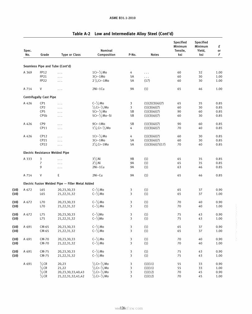
ASME B31.1-2010
Table A-2 Low and Intermediate Alloy Steel (Cont’d)
Specified SpecifiedMinimum Minimum E
Spec. Nominal Tensile, Yield, orNo. Grade Type or Class Composition P-No. Notes ksi ksi F
Seamless Pipe and Tube (Cont’d)
A 369 FP12 . . . 1Cr–1⁄2 Mo 4 . . . 60 32 1.00FP21 . . . 3Cr–1Mo 5A . . . 60 30 1.00FP22 . . . 2 1⁄4 Cr–1Mo 5A (17) 60 30 1.00
A 714 V . . . 2Ni–1Cu 9A (1) 65 46 1.00
Centrifugally Cast Pipe
A 426 CP1 . . . C–1⁄2 Mo 3 (1)(2)(3)(4)(7) 65 35 0.85CP2 . . . 1⁄2 Cr–1⁄2 Mo 3 (1)(3)(4)(7) 60 30 0.85CP5 . . . 5Cr–1⁄2 Mo 5B (1)(3)(4)(7) 90 60 0.85CP5b . . . 5Cr–1⁄2 Mo–Si 5B (1)(3)(4)(7) 60 30 0.85
A 426 CP9 . . . 9Cr–1Mo 5B (1)(3)(4)(7) 90 60 0.85CP11 . . . 11⁄4 Cr–1⁄2 Mo 4 (1)(3)(4)(7) 70 40 0.85
A 426 CP12 . . . 1Cr–1⁄2 Mo 4 (1)(3)(4)(7) 60 30 0.85CP21 . . . 3Cr–1Mo 5A (1)(3)(4)(7) 60 30 0.85CP22 . . . 21⁄4 Cr–1Mo 5A (1)(3)(4)(7)(17) 70 40 0.85
Electric Resistance Welded Pipe
A 333 3 . . . 31⁄2 Ni 9B (1) 65 35 0.857 . . . 21⁄2 Ni 9A (1) 65 35 0.859 . . . 2Ni–1Cu 9A (1) 63 46 0.85
A 714 V E 2Ni–Cu 9A (1) 65 46 0.85
Electric Fusion Welded Pipe — Filler Metal Added
(10) A 672 L65 20,23,30,33 C–1⁄2 Mo 3 (1) 65 37 0.90(10) L65 21,22,31,32 C–1⁄2 Mo 3 (1) 65 37 1.00
(10) A 672 L70 20,23,30,33 C–1⁄2 Mo 3 (1) 70 40 0.90(10) L70 21,22,31,32 C–1⁄2 Mo 3 (1) 70 40 1.00
(10) A 672 L75 20,23,30,33 C–1⁄2Mo 3 (1) 75 43 0.90(10) L75 21,22,31,32 C–1⁄2Mo 3 (1) 75 43 1.00
(10) A 691 CM-65 20,23,30,33 C–1⁄2 Mo 3 (1) 65 37 0.90(10) CM-65 21,22,31,32 C–1⁄2 Mo 3 (1) 65 37 1.00
(10) A 691 CM-70 20,23,30,33 C–1⁄2 Mo 3 (1) 70 40 0.90(10) CM-70 21,22,31,32 C–1⁄2 Mo 3 (1) 70 40 1.00
(10) A 691 CM-75 20,23,30,33 C–1⁄2 Mo 3 (1) 75 43 0.90(10) CM-75 21,22,31,32 C–1⁄2 Mo 3 (1) 75 43 1.00
A 691 1⁄2 CR 20,23 1⁄2 Cr–1⁄2 Mo 3 (1)(11) 55 33 0.901⁄2 CR 21,22 1⁄2 Cr–1⁄2 Mo 3 (1)(11) 55 33 1.001⁄2 CR 20,23,30,33,40,43 1⁄2 Cr–1⁄2 Mo 3 (1)(12) 70 45 0.901⁄2 CR 21,22,31,32,41,42 1⁄2 Cr–1⁄2 Mo 3 (1)(12) 70 45 1.00
126
Copyright ASME International Provided by IHS under license with ASME No reproduction or networking permitted without license from IHS
--`,,```````,,```,`,`,,,,`,`,`,`-`-`,,`,,`,`,,`---
标准分享网 www.bzfxw.com 免费下载

ASME B31.1-2010
Table A-2 Low and Intermediate Alloy Steel (Cont’d)
Maximum Allowable Stress Values in Tension, ksi, for Metal Temperature, °F, Not Exceeding
−20to Spec.
100 200 300 400 500 600 650 700 750 800 850 900 950 1,000 1,050 1,100 1,150 1,200 Grade No.
Seamless Pipe and Tube (Cont’d)
17.1 16.8 16.5 16.5 16.5 16.3 16.0 15.8 15.5 15.3 14.9 14.5 11.3 7.2 4.5 2.8 . . . . . . FP12 A 36917.1 17.1 16.6 16.6 16.6 16.6 16.6 16.6 16.6 16.6 16.0 12.0 9.0 7.0 5.5 4.0 . . . . . . FP2117.1 17.1 16.6 16.6 16.6 16.6 16.6 16.6 16.6 16.6 16.6 13.6 10.8 8.0 5.7 3.8 . . . . . . FP22
18.6 . . . . . . . . . . . . . . . . . . . . . . . . . . . . . . . . . . . . . . . . . . . . . . . . . . . V A 714
Centrifugally Cast Pipe
15.8 15.8 15.8 15.8 15.8 15.8 15.8 15.6 15.2 14.8 14.4 . . . . . . . . . . . . . . . . . . . . . CP1 A 42614.5 14.5 14.5 14.5 14.4 13.9 13.7 13.3 13.1 12.7 12.3 11.8 7.8 5.0 . . . . . . . . . . . . CP221.9 21.8 21.2 21.0 20.9 20.6 20.3 19.9 19.3 18.5 12.2 9.3 6.8 4.9 3.6 2.5 1.5 0.85 CP514.6 14.5 14.1 14.0 14.0 13.8 13.5 13.3 12.9 12.4 11.8 9.3 6.8 4.9 3.6 2.5 1.5 0.85 CP5b
21.9 21.8 21.2 21.0 20.9 20.7 20.3 19.9 19.3 18.5 17.7 14.0 9.4 6.3 4.3 2.8 1.9 1.3 CP9 A 42617.0 17.0 17.0 17.0 17.0 17.0 17.0 17.0 16.7 16.3 15.9 11.6 7.9 5.4 3.6 2.4 . . . . . . CP11
14.5 14.3 14.0 13.8 13.3 12.9 12.8 12.6 12.4 12.2 11.9 11.6 9.6 6.1 3.8 2.4 . . . . . . CP12 A 42614.5 14.5 14.1 14.1 14.1 14.1 14.1 14.1 14.1 14.1 13.6 10.2 7.7 6.0 4.7 3.4 . . . . . . CP2117.0 17.0 16.7 16.5 16.4 16.3 16.2 16.0 15.7 15.2 14.6 13.4 9.7 6.6 4.3 2.7 . . . . . . CP22
Electric Resistance Welded Pipe
15.8 15.8 15.8 15.8 15.8 14.9 14.2 . . . . . . . . . . . . . . . . . . . . . . . . . . . . . . . . . 3 A 33315.8 15.8 15.8 15.8 15.8 14.9 14.2 . . . . . . . . . . . . . . . . . . . . . . . . . . . . . . . . . 715.3 . . . . . . . . . . . . . . . . . . . . . . . . . . . . . . . . . . . . . . . . . . . . . . . . . . . 9
15.8 . . . . . . . . . . . . . . . . . . . . . . . . . . . . . . . . . . . . . . . . . . . . . . . . . . . V A 714
Electric Fusion Welded Pipe — Filler Metal Added
(10)16.7 16.7 16.7 16.7 16.7 16.7 16.7 16.7 16.7 16.6 16.1 . . . . . . . . . . . . . . . . . . . . . L65 A 672(10)18.6 18.6 18.6 18.6 18.6 18.6 18.6 18.6 18.6 18.4 17.9 . . . . . . . . . . . . . . . . . . . . . L65
(10)18.0 18.0 18.0 18.0 18.0 18.0 18.0 18.0 18.0 17.9 17.4 . . . . . . . . . . . . . . . . . . . . . L70 A 672(10)20.0 20.0 20.0 20.0 20.0 20.0 20.0 20.0 20.0 19.9 19.3 . . . . . . . . . . . . . . . . . . . . . L70
(10)19.3 19.3 19.3 19.3 19.3 19.3 19.3 19.3 19.3 19.3 18.7 . . . . . . . . . . . . . . . . . . . . . L75 A 672(10)21.4 21.4 21.4 21.4 21.4 21.4 21.4 21.4 21.4 21.4 20.7 . . . . . . . . . . . . . . . . . . . . . L75
(10)16.7 16.7 16.7 16.7 16.7 16.7 16.7 16.7 16.7 16.6 16.1 . . . . . . . . . . . . . . . . . . . . . CM-65 A 691(10)18.6 18.6 18.6 18.6 18.6 18.6 18.6 18.6 18.6 18.4 17.9 . . . . . . . . . . . . . . . . . . . . . CM-65
(10)18.0 18.0 18.0 18.0 18.0 18.0 18.0 18.0 18.0 17.9 17.4 . . . . . . . . . . . . . . . . . . . . . CM-70 A 691(10)20.0 20.0 20.0 20.0 20.0 20.0 20.0 20.0 20.0 19.9 19.3 . . . . . . . . . . . . . . . . . . . . . CM-70
(10)19.3 19.3 19.3 19.3 19.3 19.3 19.3 19.3 19.3 19.3 18.7 . . . . . . . . . . . . . . . . . . . . . CM-75 A 691(10)21.4 21.4 21.4 21.4 21.4 21.4 21.4 21.4 21.4 21.4 20.7 . . . . . . . . . . . . . . . . . . . . . CM-75
14.1 14.1 14.1 14.1 14.1 14.1 14.1 14.1 14.1 14.1 13.8 12.9 8.3 5.3 . . . . . . . . . . . . 1⁄2CR A 69115.7 15.7 15.7 15.7 15.7 15.7 15.7 15.7 15.7 15.7 15.3 14.3 9.2 5.9 . . . . . . . . . . . . 1⁄2CR18.0 18.0 18.0 18.0 18.0 18.0 18.0 18.0 18.0 18.0 17.6 16.7 8.3 5.3 . . . . . . . . . . . . 1⁄2CR20.0 20.0 20.0 20.0 20.0 20.0 20.0 20.0 20.0 20.0 19.5 18.6 9.2 5.9 . . . . . . . . . . . . 1⁄2CR
127
Copyright ASME International Provided by IHS under license with ASME No reproduction or networking permitted without license from IHS
--`,,```````,,```,`,`,,,,`,`,`,`-`-`,,`,,`,`,,`---

ASME B31.1-2010
Table A-2 Low and Intermediate Alloy Steel (Cont’d)
Specified SpecifiedMinimum Minimum E
Spec. Nominal Tensile, Yield, orNo. Grade Type or Class Composition P-No. Notes ksi ksi F
Electric Fusion Welded Pipe — Filler Metal Added (Cont’d)
A 691 1CR 20,23 1Cr–1⁄2 Mo 4 (1)(11) 55 33 0.901CR 21,22 1Cr–1⁄2 Mo 4 (1)(11) 55 33 1.001CR 20,23,30,33,40,43 1Cr–1⁄2 Mo 4 (1)(12) 65 40 0.901CR 21,22,31,32,41,42 1Cr–1⁄2 Mo 4 (1)(12) 65 40 1.00
A 691 11⁄4 CR 20,23 11⁄4 Cr–1⁄2 Mo–Si 4 (1)(11) 60 35 0.9011⁄4 CR 21,22 11⁄4 Cr–1⁄2 Mo–Si 4 (1)(11) 60 35 1.0011⁄4 CR 20,23,30,33,40,43 11⁄4 Cr–1⁄2 Mo–Si 4 (1)(12) 75 45 0.9011⁄4 CR 21,22,31,32,41,42 11⁄4 Cr–1⁄2 Mo–Si 4 (1)(12) 75 45 1.00
A 691 21⁄4 CR 20,23 21⁄4 Cr–1Mo 5A (1)(11)(17) 60 30 0.9021⁄4 CR 21,22 21⁄4 Cr–1Mo 5A (1)(11)(17) 60 30 1.0021⁄4 CR 20,23,30,33,40,43 21⁄4 Cr–1Mo 5A (1)(12)(17) 75 45 0.9021⁄4 CR 21,22,31,32,41,42 21⁄4 Cr–1Mo 5A (1)(12)(17) 75 45 1.00
A 691 3CR 20,23 3Cr–1Mo 5A (1)(11) 60 30 0.903CR 21,22 3Cr–1Mo 5A (1)(11) 60 30 1.003CR 20,23,30,33,40,43 3Cr–1Mo 5A (1)(12) 75 45 0.903CR 21,22,31,32,41,42 3Cr–1Mo 5A (1)(12) 75 45 1.00
A 691 5CR 20,23 5Cr–1⁄2 Mo 5B (1)(11) 60 30 0.905CR 21,22 5Cr–1⁄2 Mo 5B (1)(11) 60 30 1.005CR 20,23,30,33,40,43 5Cr–1⁄2 Mo 5B (1)(12) 75 45 0.905CR 21,22,31,32,41,42 5Cr–1⁄2 Mo 5B (1)(12) 75 45 1.00
A 691 91 40,43,50,53 9Cr–1Mo–V 15E (1)(12) 85 60 0.9091 41,42,51,52 9Cr–1Mo–V 15E (1)(12) 85 60 1.00
Plate
A 387 2 1 1⁄2 Cr–1⁄2 Mo 3 . . . 55 33 1.002 2 1⁄2 Cr–1⁄2 Mo 3 (1) 70 45 1.005 1 5Cr–1⁄2 Mo 5B . . . 60 30 1.005 2 5Cr–1⁄2 Mo 5B (1) 75 45 1.00
A 387 11 1 11⁄4 Cr–1⁄2 Mo–Si 4 . . . 60 35 1.0011 2 11⁄4 Cr–1⁄2 Mo–Si 4 . . . 75 45 1.0012 1 1Cr–1⁄2 Mo 4 . . . 55 33 1.0012 2 1Cr–1⁄2 Mo 4 . . . 65 40 1.00
A 387 21 1 3Cr–1Mo 5A . . . 60 30 1.0021 2 3Cr–1Mo 5A . . . 75 45 1.0022 1 21⁄4 Cr–1Mo 5A (17) 60 30 1.0022 2 21⁄4 Cr–1Mo 5A (17) 75 45 1.00
A 387 91 2 9Cr–1Mo–V 15E (19) 85 60 1.0091 2 9Cr–1Mo–V 15E (20) 85 60 1.00
128
Copyright ASME International Provided by IHS under license with ASME No reproduction or networking permitted without license from IHS
--`,,```````,,```,`,`,,,,`,`,`,`-`-`,,`,,`,`,,`---
标准分享网 www.bzfxw.com 免费下载

ASME B31.1-2010
Table A-2 Low and Intermediate Alloy Steel (Cont’d)
Maximum Allowable Stress Values in Tension, ksi, for Metal Temperature, °F, Not Exceeding
−20to Spec.
100 200 300 400 500 600 650 700 750 800 850 900 950 1,000 1,050 1,100 1,150 1,200 Grade No.
Electric Fusion Welded Pipe — Filler Metal Added (Cont’d)
14.1 13.9 13.6 13.6 13.6 13.6 13.6 13.6 13.6 13.6 13.6 13.2 10.2 6.5 4.1 2.5 . . . . . . 1CR A 69115.7 15.4 15.1 15.1 15.1 15.1 15.1 15.1 15.1 15.1 15.1 14.7 11.3 7.2 4.5 2.8 . . . . . . 1CR16.7 16.4 16.1 16.1 16.1 16.1 16.1 16.1 16.1 16.1 16.1 15.6 10.2 6.5 4.1 2.5 . . . . . . 1CR18.6 18.2 17.9 17.9 17.9 17.9 17.9 17.9 17.9 17.9 17.9 17.4 11.3 7.2 4.5 2.8 . . . . . . 1CR
15.4 15.4 15.4 15.4 15.4 15.4 15.4 15.4 15.4 15.1 14.7 12.3 8.4 5.7 3.8 2.5 . . . . . . 11⁄4CR A 69117.1 17.1 17.1 17.1 17.1 17.1 17.1 17.1 17.1 16.8 16.4 13.7 9.3 6.3 4.2 2.8 . . . . . . 11⁄4CR19.3 19.3 19.3 19.3 19.3 19.3 19.3 19.3 19.3 19.3 18.2 12.3 8.4 5.7 3.8 2.5 . . . . . . 11⁄4CR21.4 21.4 21.4 21.4 21.4 21.4 21.4 21.4 21.4 21.4 20.2 13.7 9.3 6.3 4.2 2.8 . . . . . . 11⁄4CR
15.4 15.4 15.0 14.9 14.8 14.6 14.4 14.2 14.0 13.7 13.4 13.0 10.3 7.0 4.6 2.9 . . . . . . 21⁄4CR A 69117.1 17.1 16.6 16.6 16.6 16.6 16.6 16.6 16.6 16.6 16.6 13.6 10.8 8.0 5.7 3.8 . . . . . . 21⁄4CR19.3 19.3 18.8 18.6 18.5 18.3 18.2 18.0 17.7 17.4 16.8 14.2 10.3 7.0 4.6 2.9 . . . . . . 21⁄4CR21.4 21.4 20.9 20.6 20.5 20.4 20.2 20.0 19.7 19.3 18.7 15.8 11.4 7.8 5.1 3.2 . . . . . . 21⁄4CR
15.4 15.4 15.0 15.0 15.0 15.0 15.0 15.0 15.0 15.0 14.4 10.8 8.1 6.3 5.0 3.6 . . . . . . 3CR A 69117.1 17.1 16.6 16.6 16.6 16.6 16.6 16.6 16.6 16.6 16.0 12.0 9.0 7.0 5.5 4.0 . . . . . . 3CR19.3 19.3 18.8 18.6 18.5 18.3 18.2 18.0 17.7 17.4 16.3 11.8 8.6 6.1 4.4 2.9 . . . . . . 3CR21.4 21.4 20.9 20.6 20.5 20.4 20.2 20.0 19.7 19.3 18.1 13.1 9.5 6.8 4.9 3.2 . . . . . . 3CR
15.4 15.4 14.9 14.8 14.8 14.6 14.3 14.0 13.6 13.1 12.5 9.8 7.2 5.2 3.8 2.6 1.6 0.9 5CR A 69117.1 17.1 16.6 16.5 16.4 16.2 15.9 15.6 15.1 14.5 13.8 10.9 8.0 5.8 4.2 2.9 1.8 1.0 5CR19.3 19.2 18.7 18.5 18.5 18.2 17.9 17.5 17.0 16.4 12.9 9.8 7.2 5.2 3.8 2.6 1.6 0.9 5CR21.4 21.4 20.8 20.6 20.5 20.2 19.9 19.5 18.9 18.2 14.3 10.9 8.0 5.8 4.2 2.9 1.8 1.0 5CR
21.9 21.9 21.9 21.8 21.7 21.4 21.0 20.6 20.0 19.2 18.3 17.2 16.0 14.7 12.6 9.3 6.3 3.8 91 A 69124.3 24.3 24.3 24.2 24.1 23.7 23.4 22.9 22.2 21.3 20.3 19.1 17.8 16.3 14.0 10.3 7.0 4.3 91
Plate
15.7 15.7 15.7 15.7 15.7 15.7 15.7 15.7 15.7 15.7 15.3 14.3 9.2 5.9 . . . . . . . . . . . . 2 A 38720.0 20.0 20.0 20.0 20.0 20.0 20.0 20.0 20.0 20.0 19.5 18.6 9.2 5.9 . . . . . . . . . . . . 217.1 17.1 16.6 16.5 16.4 16.2 15.9 15.6 15.1 14.5 13.8 10.9 8.0 5.8 4.2 2.9 1.8 1.0 521.4 21.4 20.8 20.6 20.5 20.2 19.9 19.5 18.9 18.2 14.3 10.9 8.0 5.8 4.2 2.9 1.8 1.0 5
17.1 17.1 17.1 17.1 17.1 17.1 17.1 17.1 17.1 16.8 16.4 13.7 9.3 6.3 4.2 2.8 . . . . . . 11 A 38721.4 21.4 21.4 21.4 21.4 21.4 21.4 21.4 21.4 21.4 20.2 13.7 9.3 6.3 4.2 2.8 . . . . . . 1115.7 15.4 15.1 15.1 15.1 15.1 15.1 15.1 15.1 15.1 15.1 14.7 11.3 7.2 4.5 2.8 . . . . . . 1218.6 18.2 17.9 17.9 17.9 17.9 17.9 17.9 17.9 17.9 17.9 17.4 11.3 7.2 4.5 2.8 . . . . . . 12
17.1 17.1 16.6 16.6 16.6 16.6 16.6 16.6 16.6 16.6 16.0 12.0 9.0 7.0 5.5 4.0 . . . . . . 21 A 38721.4 21.4 20.9 20.6 20.5 20.4 20.2 20.0 19.7 19.3 18.1 13.1 9.5 6.8 4.9 3.2 . . . . . . 2117.1 17.1 16.6 16.6 16.6 16.6 16.6 16.6 16.6 16.6 16.6 13.6 10.8 8.0 5.7 3.8 . . . . . . 2221.4 21.4 20.9 20.6 20.5 20.4 20.2 20.0 19.7 19.3 18.7 15.8 11.4 7.8 5.1 3.2 . . . . . . 22
24.3 24.3 24.3 24.2 24.1 23.7 23.4 22.9 22.2 21.3 20.3 19.1 17.8 16.3 14.0 10.3 7.0 4.3 91 A 38724.3 24.3 24.3 24.2 24.1 23.7 23.4 22.9 22.2 21.3 20.3 19.1 17.8 16.3 12.9 9.6 7.0 4.3 91
129
Copyright ASME International Provided by IHS under license with ASME No reproduction or networking permitted without license from IHS
--`,,```````,,```,`,`,,,,`,`,`,`-`-`,,`,,`,`,,`---

ASME B31.1-2010
Table A-2 Low and Intermediate Alloy Steel (Cont’d)
Specified SpecifiedMinimum Minimum E
Spec. Nominal Tensile, Yield, orNo. Grade Type or Class Composition P-No. Notes ksi ksi F
Forgings
A 182 F1 . . . C–1⁄2 Mo 3 (2) 70 40 1.00F2 . . . 1⁄2 Cr–1⁄2 Mo 3 . . . 70 40 1.00F5 . . . 5Cr–1⁄2 Mo 5B . . . 70 40 1.00F5a . . . 5Cr–1⁄2 Mo 5B . . . 90 65 1.00
A 182 F9 . . . 9Cr–1Mo 5B . . . 85 55 1.00(10) F91 . . . 9Cr–1Mo–V 15E . . . 85 60 1.00
F11 Class 1 11⁄4 Cr–1⁄2 Mo–Si 4 . . . 60 30 1.00F11 Class 2 11⁄4 Cr–1⁄4 Mo–Si 4 . . . 70 40 1.00
(10) F11 Class 3 11⁄4 Cr–1⁄2 Mo–Si 4 . . . 75 45 1.00F12 Class 1 1Cr–1⁄2 Mo 4 . . . 60 30 1.00F12 Class 2 1Cr–1⁄2 Mo 4 . . . 70 40 1.00F21 . . . 3Cr–1Mo 5A . . . 75 45 1.00F22 Class 1 21⁄4 Cr–1Mo 5A (17) 60 30 1.00F22 Class 3 21⁄4 Cr–1Mo 5A (17) 75 45 1.00
A 336 F1 . . . C–1⁄2Mo 3 (2) 70 40 1.00F5 . . . 5Cr–1⁄2Mo 5B . . . 60 36 1.00F5A . . . 5Cr–1⁄2Mo 5B . . . 80 50 1.00F11 Class 1 11⁄4 Cr–1⁄2 Mo–Si 4 . . . 60 30 1.00F11 Class 2 11⁄4 Cr–1⁄2 Mo–Si 4 . . . 70 40 1.00
(10) F11 Class 3 11⁄4 Cr–1⁄2 Mo–Si 4 . . . 75 45 1.00F12 . . . 1Cr–1⁄2 Mo 4 . . . 70 40 1.00F21 Class 1 3Cr–1Mo 5A . . . 60 30 1.00F21 Class 3 3Cr–1Mo 5A . . . 75 45 1.00F22 Class 1 21⁄4 Cr–1Mo 5A (17) 60 30 1.00F22 Class 3 21⁄4 Cr–1Mo 5A (17) 75 45 1.00F91 . . . 9Cr–1Mo–V 15E (19) 85 60 1.00F91 . . . 9Cr–1Mo–V 15E (20) 85 60 1.00
A 350 LF3 . . . 31⁄2 Ni 9B (1) 70 40 1.00LF4 . . . 3⁄4 Cr–3⁄4Ni–Cu–Al 4 (1) 60 . . . 1.00LF5 Class 1 11⁄2 Ni 9A (1) 60 30 1.00LF5 Class 2 11⁄2 Ni 9A (1) 70 37 1.00LF9 . . . 2Ni–1Cu 9A (1) 63 46 1.00
Wrought Fittings (Seamless and Welded)
A 234 WP1 . . . C–1⁄2 Mo 3 (2) 55 30 1.00(10) WP5 Class 1 5Cr–1⁄2 Mo 5B . . . 60 30 1.00(10) WP5 Class 3 5Cr–1⁄2 Mo 5B . . . 75 45 1.00(10) WP9 Class 1 9Cr–1Mo 5B . . . 60 30 1.00
WP11 Class 1 11⁄4 Cr–1⁄2 Mo 4 . . . 60 30 1.00(10) WP11 Class 3 11⁄4 Cr–1⁄2 Mo 4 . . . 75 45 1.00(10) WP12 Class 1 1Cr–1⁄2 Mo 4 (6) 60 32 1.00(10) WP12 Class 2 1Cr–1⁄2 Mo 4 . . . 70 40 1.00
A 234 WP22 Class 1 21⁄4 Cr–1Mo 5A (17) 60 30 1.00(10) WP22 Class 3 21⁄4 Cr–1Mo 5A (17) 75 45 1.00
WP91 . . . 9Cr–1Mo–V 15E (19) 85 60 1.00WP91 . . . 9Cr–1Mo–V 15E (20) 85 60 1.00
130
Copyright ASME International Provided by IHS under license with ASME No reproduction or networking permitted without license from IHS
--`,,```````,,```,`,`,,,,`,`,`,`-`-`,,`,,`,`,,`---
标准分享网 www.bzfxw.com 免费下载

ASME B31.1-2010
Table A-2 Low and Intermediate Alloy Steel (Cont’d)
Maximum Allowable Stress Values in Tension, ksi, for Metal Temperature, °F, Not Exceeding
−20to Spec.
100 200 300 400 500 600 650 700 750 800 850 900 950 1,000 1,050 1,100 1,150 1,200 Grade No.
Forgings
20.0 20.0 20.0 20.0 20.0 20.0 20.0 20.0 20.0 19.9 19.3 . . . . . . . . . . . . . . . . . . . . . F1 A 18220.0 20.0 20.0 20.0 20.0 20.0 20.0 20.0 20.0 19.9 19.3 18.6 9.2 5.9 . . . . . . . . . . . . F220.0 20.0 19.4 19.2 19.2 18.9 18.6 18.2 17.6 17.0 14.3 10.9 8.0 5.8 4.2 2.9 1.8 1.0 F525.7 25.7 24.9 24.7 24.6 24.3 23.9 23.4 22.7 19.1 14.3 10.9 8.0 5.8 4.2 2.9 1.8 1.0 F5a
24.3 24.2 23.5 23.4 23.3 22.9 22.6 22.1 21.4 20.6 19.6 16.4 11.0 7.4 5.0 3.3 2.2 1.5 F9 A 182(10)24.3 24.3 24.3 24.2 24.1 23.7 23.4 22.9 22.2 21.3 20.3 19.1 17.8 16.3 14.0 10.3 7.0 4.3 F91
17.1 17.1 17.1 16.8 16.2 15.7 15.4 15.1 14.8 14.4 14.0 13.6 9.3 6.3 4.2 2.8 . . . . . . F1120.0 20.0 20.0 20.0 20.0 20.0 20.0 20.0 19.7 19.2 18.7 13.7 9.3 6.3 4.2 2.8 . . . . . . F11
(10)21.4 21.4 21.4 21.4 21.4 21.4 21.4 21.4 21.4 21.4 20.2 13.7 9.3 6.3 4.2 2.8 . . . . . . F1117.1 16.8 16.5 16.5 16.5 16.3 16.0 15.8 15.5 15.3 14.9 14.5 11.3 7.2 4.5 2.8 . . . . . . F1220.0 19.6 19.2 19.2 19.2 19.2 19.2 19.2 19.2 19.1 18.6 18.0 11.3 7.2 4.5 2.8 . . . . . . F1221.4 21.4 20.9 20.6 20.5 20.4 20.2 20.0 19.7 19.3 18.1 13.1 9.5 6.8 4.9 3.2 . . . . . . F2117.1 17.1 16.6 16.6 16.6 16.6 16.6 16.6 16.6 16.6 16.6 13.6 10.8 8.0 5.7 3.8 . . . . . . F2221.4 21.4 20.9 20.6 20.5 20.4 20.2 20.0 19.7 19.3 18.7 15.8 11.4 7.8 5.1 3.2 . . . . . . F22
20.0 20.0 20.0 20.0 20.0 20.0 20.0 20.0 20.0 19.9 19.3 13.7 8.2 4.8 . . . . . . . . . . . . F1 A 33617.1 17.1 16.6 16.5 16.4 16.2 15.9 15.6 15.1 14.5 13.8 10.9 8.0 5.8 4.2 2.9 1.8 1.0 F522.9 22.8 22.1 22.0 21.9 21.6 21.3 20.8 20.2 19.1 14.3 10.9 8.0 5.8 4.2 2.9 1.8 1.0 F5A17.1 17.1 17.1 16.8 16.2 15.7 15.4 15.1 14.8 14.4 14.0 13.6 9.3 6.3 4.2 2.8 . . . . . . F1120.0 20.0 20.0 20.0 20.0 20.0 20.0 20.0 19.7 19.2 18.7 13.7 9.3 6.3 4.2 2.8 . . . . . . F11
(10)21.4 21.4 21.4 21.4 21.4 21.4 21.4 21.4 21.4 21.4 20.2 13.7 9.3 6.3 4.2 2.8 . . . . . . F1120.0 19.6 19.2 19.2 19.2 19.2 19.2 19.2 19.2 19.1 18.6 18.0 11.3 7.2 4.5 2.8 . . . . . . F1217.1 17.1 16.6 16.6 16.6 16.6 16.6 16.6 16.6 16.6 16.0 12.0 9.0 7.0 5.5 4.0 2.7 1.5 F2121.4 21.4 20.9 20.6 20.5 20.4 20.2 20.0 19.7 19.3 18.1 13.1 9.5 6.8 4.9 3.2 2.4 1.3 F2117.1 17.1 16.6 16.6 16.6 16.6 16.6 16.6 16.6 16.6 16.6 13.6 10.8 8.0 5.7 3.8 . . . . . . F2221.4 21.4 20.9 20.6 20.5 20.4 20.2 20.0 19.7 19.3 18.7 15.8 11.4 7.8 5.1 3.2 . . . . . . F2224.3 24.3 24.3 24.2 24.1 23.7 23.4 22.9 22.2 21.3 20.3 19.1 17.8 16.3 14.0 10.3 7.0 4.3 F9124.3 24.3 24.3 24.2 24.1 23.7 23.4 22.9 22.2 21.3 20.3 19.1 17.8 16.3 12.9 9.6 7.0 4.3 F91
20.0 20.0 20.0 20.0 20.0 18.8 17.9 . . . . . . . . . . . . . . . . . . . . . . . . . . . . . . . . . LF3 A 35017.1 17.1 17.1 17.1 17.1 17.1 17.1 . . . . . . . . . . . . . . . . . . . . . . . . . . . . . . . . . LF417.1 16.5 15.7 15.3 15.3 . . . . . . . . . . . . . . . . . . . . . . . . . . . . . . . . . . . . . . . LF520.0 19.2 18.3 17.8 17.8 . . . . . . . . . . . . . . . . . . . . . . . . . . . . . . . . . . . . . . . LF518.0 . . . . . . . . . . . . . . . . . . . . . . . . . . . . . . . . . . . . . . . . . . . . . . . . . . . LF9
Wrought Fittings (Seamless and Welded)
15.7 15.7 15.7 15.7 15.7 15.7 15.7 15.7 15.4 14.9 14.5 . . . . . . . . . . . . . . . . . . . . . WP1 A 234(10)17.1 17.1 16.6 16.5 16.4 16.2 15.9 15.6 15.1 14.5 13.8 10.9 8.0 5.8 4.2 2.9 1.8 1.0 WP5(10)21.4 21.4 20.8 20.6 20.5 20.2 19.9 19.5 18.9 18.2 14.3 10.9 8.0 5.8 4.2 2.9 1.8 1.0 WP5(10)17.1 17.1 16.6 16.5 16.4 16.2 15.9 15.6 15.1 14.5 13.8 13.0 10.6 7.4 5.0 3.3 2.2 1.5 WP9
17.1 17.1 17.1 16.8 16.2 15.7 15.4 15.1 14.8 14.4 14.0 13.6 9.3 6.3 4.2 2.8 . . . . . . WP11(10)21.4 21.4 21.4 21.4 21.4 21.4 21.4 21.4 21.4 21.4 20.2 13.7 9.3 6.3 4.2 2.8 . . . . . . WP11(10)17.1 16.8 16.5 16.5 16.5 16.3 16.0 15.8 15.5 15.3 14.9 14.5 11.3 7.2 4.5 2.8 . . . . . . WP12(10)20.0 19.6 19.2 19.2 19.2 19.2 19.2 19.2 19.2 19.1 18.6 18.0 11.3 7.2 4.5 2.8 . . . . . . WP12
17.1 17.1 16.6 16.6 16.6 16.6 16.6 16.6 16.6 16.6 16.6 13.6 10.8 8.0 5.7 3.8 . . . . . . WP22 A 234(10)21.4 21.4 20.9 20.6 20.5 20.4 20.2 20.0 19.7 19.3 18.7 15.8 11.4 7.8 5.1 3.2 . . . . . . WP22
24.3 24.3 24.3 24.2 24.1 23.7 23.4 22.9 22.2 21.3 20.3 19.1 17.8 16.3 14.0 10.3 7.0 4.3 WP9124.3 24.3 24.3 24.2 24.1 23.7 23.4 22.9 22.2 21.3 20.3 19.1 17.8 16.3 12.9 9.6 7.0 4.3 WP91
131
Copyright ASME International Provided by IHS under license with ASME No reproduction or networking permitted without license from IHS
--`,,```````,,```,`,`,,,,`,`,`,`-`-`,,`,,`,`,,`---

ASME B31.1-2010
Table A-2 Low and Intermediate Alloy Steel (Cont’d)
Specified SpecifiedMinimum Minimum E
Spec. Nominal Tensile, Yield, orNo. Grade Type or Class Composition P-No. Notes ksi ksi F
Castings
A 217 WC1 . . . C–1⁄2 Mo 3 (2)(3)(4) 65 35 0.80WC4 . . . 1Ni–1⁄2Cr–1⁄2Mo 4 (3)(4) 70 40 0.80WC5 . . . 3⁄4 Ni–1Mo–3⁄4Cr 4 (3)(4) 70 40 0.80WC6 . . . 11⁄4 Cr–1⁄2 Mo 4 (3)(4) 70 40 0.80
A 217 WC9 . . . 21⁄4 Cr–1Mo 5A (3)(4) 70 40 0.80C5 . . . 5Cr–1⁄2 Mo 5B (3)(4) 90 60 0.80C12 . . . 9Cr–1Mo 5B (3)(4) 90 60 0.80C12A . . . 9Cr–1Mo–V 15E (3)(4) 85 60 0.80
(10)
GENERAL NOTES:(a) The tabulated specifications are ANSI/ASTM or ASTM. For ASME Boiler and Pressure Vessel Code applications, see related specifica-
tions in Section II of the ASME Code.(b) The stress values in this Table may be interpolated to determine values for intermediate temperatures.(c) The P-Numbers indicated in this Table are identical to those adopted by the ASME Boiler and Pressure Vessel Code, Section IX, except
as modified by para. 127.5.(d) Tensile strengths and allowable stresses shown in “ksi” are “thousands of pounds per square inch.”(e) The materials listed in this Table shall not be used at design temperatures above those for which allowable stress values are given.(f) The tabulated stress values are S � E (weld joint efficiency factor) or S � F (material quality factor), as applicable. Weld joint effi-
ciency factors are shown in Table 102.4.3.(g) Pressure-temperature ratings of piping components, as published in standards referenced in this Code, may be used for components
meeting the requirements of those standards. The allowable stress values given in this Table are for use in designing piping compo-nents which are not manufactured in accordance with referenced standards.
(h) All the materials listed are classifed as ferritic [see Table 104.1.2(A)].(i) The tabulated stress values that are shown in italics are at temperatures in the range where creep and stress rupture strength govern
the selection of stresses.
132
Copyright ASME International Provided by IHS under license with ASME No reproduction or networking permitted without license from IHS
--`,,```````,,```,`,`,,,,`,`,`,`-`-`,,`,,`,`,,`---
标准分享网 www.bzfxw.com 免费下载

ASME B31.1-2010
Table A-2 Low and Intermediate Alloy Steel (Cont’d)
Maximum Allowable Stress Values in Tension, ksi, for Metal Temperature, °F, Not Exceeding
−20to Spec.
100 200 300 400 500 600 650 700 750 800 850 900 950 1,000 1,050 1,100 1,150 1,200 Grade No.
Castings
14.9 14.9 14.9 14.9 14.9 14.9 14.9 14.7 14.3 13.9 13.5 . . . . . . . . . . . . . . . . . . . . . WC1 A 21716.0 16.0 16.0 16.0 16.0 16.0 16.0 16.0 16.0 16.0 15.4 12.0 7.4 4.7 . . . . . . . . . . . . WC416.0 16.0 16.0 16.0 16.0 16.0 16.0 16.0 16.0 16.0 15.4 13.0 8.8 5.5 3.7 2.2 . . . . . . WC516.0 16.0 16.0 16.0 16.0 16.0 16.0 16.0 15.8 15.4 15.0 11.0 7.4 5.0 3.4 2.2 . . . . . . WC6
16.0 16.0 15.8 15.5 15.4 15.4 15.3 15.0 14.8 14.3 13.8 12.6 9.1 6.2 4.1 2.6 . . . . . . WC9 A 21720.6 20.6 19.9 19.8 19.7 19.4 19.1 18.7 18.2 15.3 11.4 8.7 6.4 4.6 3.4 2.3 1.4 0.8 C520.6 20.6 19.9 19.8 19.7 19.4 19.1 18.7 18.2 17.4 16.6 13.1 8.8 5.9 4.0 2.6 1.8 1.2 C1219.4 19.4 19.4 19.4 19.3 19.0 18.7 18.3 17.7 17.1 16.2 15.3 14.2 13.0 11.2 8.2 5.6 3.4 C12A
(10)
(10)NOTES:(1) THIS MATERIAL IS NOT ACCEPTABLE FOR USE ON BOILER EXTERNAL PIPING — SEE FIGS. 100.1.2(A) AND (B).(2) Upon prolonged exposure to temperature above 875°F, the carbide phase of carbon-molybdenum steel may be converted to
graphite.(3) These allowable stress values apply to normalized and tempered material only.(4) The material quality factors and allowable stress values for these materials may be increased in accordance with para. 102.4.6.(5) . . .(6) If A 234 Grade WP-12 fittings are made from A 387 Grade 12 Class 1 plate, the allowable stress values shall be reduced by the ratio
of 55 divided by 60 in the temperature range —20°F through 850°F. At 900°F through 1,100°F, the values shown may be used.(7) The mutual quality factor for centrifugally cast pipe (0.85) is based on all surfaces being machined, after heat treatment, to a surface
finish of 250 �in. arithmetic average deviation or better.(8) DELETED.(9) DELETED.(10) DELETED.(11) These allowable stress values are for pipe fabricated from ASTM A 387 Class 1 plate in the annealed condition.(12) These allowable stress values are for pipe fabricated from ASTM A 387 Class 2 plate.(13) DELETED.(14) DELETED.(15) DELETED.(16) DELETED.(17) For use at temperatures above 850°F, the carbon content of the base material and, where applicable, weld filler metal shall be
0.05% or higher. See para. 124.2(D).(18) DELETED.(19) These allowable stress values apply to thickness less than 3 in.(20) These allowable stress values apply to thickness 3 in. or greater.
133
Copyright ASME International Provided by IHS under license with ASME No reproduction or networking permitted without license from IHS
--`,,```````,,```,`,`,,,,`,`,`,`-`-`,,`,,`,`,,`---

ASME B31.1-2010
Table A-3 Stainless Steels
Specified SpecifiedUNS Minimum Minimum E
Spec. Type or Alloy Nominal P- Tensile, Yield, orNo. Grade Class No. Composition No. Notes ksi ksi F
Seamless Pipe and TubeAustenitic
A 213 TP304 . . . S30400 18Cr–8Ni 8 (10) 75 30 1.00TP304 . . . S30400 18Cr–8Ni 8 (9)(10) 75 30 1.00TP304H . . . S30409 18Cr–8Ni 8 . . . 75 30 1.00TP304H . . . S30409 18Cr–8Ni 8 (9) 75 30 1.00
A 213 TP304L . . . S30403 18Cr–8Ni 8 (1) 70 25 1.00TP304L . . . S30403 18Cr–8Ni 8 (1)(9) 70 25 1.00TP304N . . . S30451 18Cr–8Ni–N 8 (10) 80 35 1.00TP304N . . . S30451 18Cr–8Ni–N 8 (9)(10) 80 35 1.00
A 213 . . . . . . S30815 21Cr–11Ni–N 8 (1) 87 45 1.00. . . . . . S30815 21Cr–11Ni–N 8 (1)(9) 87 45 1.00
A 213 TP309H S30909 23Cr–12Ni 8 (9) 75 30 1.00TP309H S30909 23Cr–12Ni 8 . . . 75 30 1.00TP310H S31009 25Cr–20Ni 8 (9) 75 30 1.00TP310H S31009 25Cr–20Ni 8 . . . 75 30 1.00
A 213 TP316 . . . S31600 16Cr–12Ni–2Mo 8 (10) 75 30 1.00TP316 . . . S31600 16Cr–12Ni–2Mo 8 (9)(10) 75 30 1.00TP316H . . . S31609 16Cr–12Ni–2Mo 8 . . . 75 30 1.00TP316H . . . S31609 16Cr–12Ni–2Mo 8 (9) 75 30 1.00
A 213 TP316L . . . S31603 16Cr–12Ni–2Mo 8 (1) 70 25 1.00TP316L . . . S31603 16Cr–12Ni–2Mo 8 (1)(9) 70 25 1.00TP316N . . . S31651 16Cr–12Ni–2Mo–N 8 (10) 80 35 1.00TP316N . . . S31651 16Cr–12Ni–2Mo–N 8 (9)(10) 80 35 1.00
A 213 TP321 . . . S32100 18Cr–10Ni–Ti 8 (10) 75 30 1.00TP321 . . . S32100 18Cr–10Ni–Ti 8 (9)(10) 75 30 1.00TP321H . . . S32109 18Cr–10Ni–Ti 8 . . . 75 30 1.00TP321H . . . S32109 18Cr–10Ni–Ti 8 (9) 75 30 1.00
A 213 TP347 . . . S34700 18Cr–10Ni–Cb 8 (10) 75 30 1.00TP347 . . . S34700 18Cr–10Ni–Cb 8 (9)(10) 75 30 1.00TP347H . . . S34709 18Cr–10Ni–Cb 8 . . . 75 30 1.00TP347H . . . S34709 18Cr–10Ni–Cb 8 (9) 75 30 1.00
A 213 TP348 . . . S34800 18Cr–10Ni–Cb 8 (10) 75 30 1.00TP348 . . . S34800 18Cr–10Ni–Cb 8 (9)(10) 75 30 1.00TP348H . . . S34809 18Cr–10Ni–Cb 8 . . . 75 30 1.00TP348H . . . S34809 18Cr–10Ni–Cb 8 (9) 75 30 1.00
A 312 TP304 . . . S30400 18Cr–8Ni 8 (10) 75 30 1.00TP304 . . . S30400 18Cr–8Ni 8 (9)(10) 75 30 1.00TP304H . . . S30409 18Cr–8Ni 8 . . . 75 30 1.00TP304H . . . S30409 18Cr–8Ni 8 (9) 75 30 1.00
134
Copyright ASME International Provided by IHS under license with ASME No reproduction or networking permitted without license from IHS
--`,,```````,,```,`,`,,,,`,`,`,`-`-`,,`,,`,`,,`--- 标准分享网 www.bzfxw.com 免费下载

ASME B31.1-2010
Table A-3 Stainless Steels
Maximum Allowable Stress Values in Tension, ksi, for Metal Temperature, °F, Not Exceeding
−20 Typeto or Spec.
100 200 300 400 500 600 650 700 750 800 850 900 950 1,000 1,050 1,100 1,150 1,200 Grade No.
Seamless Pipe and TubeAustenitic
20.0 16.7 15.0 13.8 12.9 12.3 12.0 11.7 11.5 11.2 11.0 10.8 10.6 10.4 10.1 9.8 7.7 6.1 TP304 A 21320.0 20.0 18.9 18.3 17.5 16.6 16.2 15.8 15.5 15.2 14.9 14.6 14.3 14.0 12.4 9.8 7.7 6.1 TP30420.0 16.7 15.0 13.8 12.9 12.3 12.0 11.7 11.5 11.2 11.0 10.8 10.6 10.4 10.1 9.8 7.7 6.1 TP304H20.0 20.0 18.9 18.3 17.5 16.6 16.2 15.8 15.5 15.2 14.9 14.6 14.3 14.0 12.4 9.8 7.7 6.1 TP304H
16.7 14.3 12.8 11.7 10.9 10.4 10.2 10.0 9.8 9.7 . . . . . . . . . . . . . . . . . . . . . . . . TP304L A 21316.7 16.7 16.7 15.8 14.7 14.0 13.7 13.5 13.3 13.0 . . . . . . . . . . . . . . . . . . . . . . . . TP304L22.9 19.1 16.7 15.1 14.0 13.3 13.0 12.8 12.5 12.3 12.1 11.8 11.6 11.3 11.0 9.8 7.7 6.1 TP304N22.9 22.9 21.7 20.3 18.9 17.9 17.5 17.2 16.9 16.6 16.3 16.0 15.6 15.2 12.4 9.8 7.7 6.1 TP304N
24.9 24.7 22.0 19.9 18.5 17.7 17.4 17.2 17.0 16.8 16.6 16.4 16.2 14.9 11.6 9.0 6.9 5.2 . . . A 21324.9 24.7 23.3 22.4 21.8 21.4 21.2 21.0 20.8 20.6 20.3 20.0 19.1 14.9 11.6 9.0 6.9 5.2 . . .
20.0 20.0 20.0 20.0 19.4 18.8 18.5 18.2 18.0 17.7 17.5 17.2 16.9 13.8 10.3 7.6 5.5 4.0 TP309H A 21320.0 17.5 16.1 15.1 14.4 13.9 13.7 13.5 13.3 13.1 12.9 12.7 12.5 12.3 10.3 7.6 5.5 4.0 TP309H20.0 20.0 20.0 19.9 19.3 18.5 18.2 17.9 17.7 17.4 17.2 16.9 16.7 13.8 10.3 7.6 5.5 4.0 TP310H20.0 17.6 16.1 15.1 14.3 13.7 13.5 13.3 13.1 12.9 12.7 12.5 12.3 12.1 10.3 7.6 5.5 4.0 TP310H
20.0 17.3 15.6 14.3 13.3 12.6 12.3 12.1 11.9 11.8 11.6 11.5 11.4 11.3 11.2 11.1 9.8 7.4 TP316 A 21320.0 20.0 20.0 19.3 18.0 17.0 16.6 16.3 16.1 15.9 15.7 15.6 15.4 15.3 15.1 12.4 9.8 7.4 TP31620.0 17.3 15.6 14.3 13.3 12.6 12.3 12.1 11.9 11.8 11.6 11.5 11.4 11.3 11.2 11.1 9.8 7.4 TP316H20.0 20.0 20.0 19.3 18.0 17.0 16.6 16.3 16.1 15.9 15.7 15.6 15.4 15.3 15.1 12.4 9.8 7.4 TP316H
16.7 14.1 12.7 11.7 10.9 10.4 10.2 10.0 9.8 9.6 9.4 9.2 8.9 8.8 8.0 7.9 6.5 6.4 TP316L A 21316.7 16.7 16.0 15.6 14.8 14.0 13.8 13.5 13.2 13.0 12.7 12.4 12.0 11.9 10.8 10.2 8.8 6.4 TP316L22.9 20.7 19.0 17.6 16.5 15.6 15.2 14.9 14.5 14.2 13.9 13.7 13.4 13.2 12.9 12.3 9.8 7.4 TP316N22.9 22.9 22.0 21.5 21.2 21.0 20.5 20.0 19.6 19.2 18.8 18.5 18.1 17.8 15.8 12.3 9.8 7.4 TP316N
20.0 18.0 16.5 15.3 14.3 13.5 13.2 13.0 12.7 12.6 12.4 12.3 12.1 12.0 9.6 6.9 5.0 3.6 TP321 A 21320.0 20.0 19.1 18.7 18.7 18.3 17.9 17.5 17.2 16.9 16.7 16.5 16.4 16.2 9.6 6.9 5.0 3.6 TP32120.0 18.0 16.5 15.3 14.3 13.5 13.2 13.0 12.7 12.6 12.4 12.3 12.1 12.0 11.9 9.1 6.9 5.4 TP321H20.0 20.0 19.1 18.7 18.7 18.3 17.9 17.5 17.2 16.9 16.7 16.5 16.4 16.2 12.3 9.1 6.9 5.4 TP321H
20.0 18.4 17.1 16.0 15.0 14.3 14.0 13.8 13.7 13.6 13.5 13.4 13.4 13.4 12.1 9.1 6.1 4.4 TP347 A 21320.0 20.0 18.8 17.8 17.2 16.9 16.8 16.8 16.8 16.8 16.8 16.7 16.6 16.0 12.1 9.1 6.1 4.4 TP34720.0 18.4 17.1 16.0 15.0 14.3 14.0 13.8 13.7 13.6 13.5 13.4 13.4 13.4 13.4 13.3 10.5 7.9 TP347H20.0 20.0 18.8 17.8 17.1 16.9 16.8 16.8 16.8 16.8 16.8 16.7 16.6 16.4 16.2 14.1 10.5 7.9 TP347H
20.0 18.4 17.1 16.0 15.0 14.3 14.0 13.8 13.7 13.6 13.5 13.4 13.4 13.4 12.1 9.1 6.1 4.4 TP348 A 21320.0 20.0 18.8 17.8 17.2 16.9 16.8 16.8 16.8 16.8 16.8 16.7 16.6 16.0 12.1 9.1 6.1 4.4 TP34820.0 18.4 17.1 16.0 15.0 14.3 14.0 13.8 13.7 13.6 13.5 13.4 13.4 13.4 13.4 13.3 10.5 7.9 TP348H20.0 20.0 18.8 17.8 17.1 16.9 16.8 16.8 16.8 16.8 16.8 16.7 16.6 16.4 16.2 14.1 10.5 7.9 TP348H
20.0 16.7 15.0 13.8 12.9 12.3 12.0 11.7 11.5 11.2 11.0 10.8 10.6 10.4 10.1 9.8 7.7 6.1 TP304 A 31220.0 20.0 18.9 18.3 17.5 16.6 16.2 15.8 15.5 15.2 14.9 14.6 14.3 14.0 12.4 9.8 7.7 6.1 TP30420.0 16.7 15.0 13.8 12.9 12.3 12.0 11.7 11.5 11.2 11.0 10.8 10.6 10.4 10.1 9.8 7.7 6.1 TP304H20.0 20.0 18.9 18.3 17.5 16.6 16.2 15.8 15.5 15.2 14.9 14.6 14.3 14.0 12.4 9.8 7.7 6.1 TP304H
135
Copyright ASME International Provided by IHS under license with ASME No reproduction or networking permitted without license from IHS
--`,,```````,,```,`,`,,,,`,`,`,`-`-`,,`,,`,`,,`---
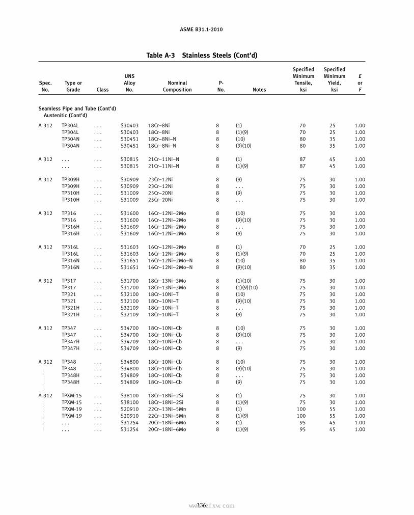
ASME B31.1-2010
Table A-3 Stainless Steels (Cont’d)
Specified SpecifiedUNS Minimum Minimum E
Spec. Type or Alloy Nominal P- Tensile, Yield, orNo. Grade Class No. Composition No. Notes ksi ksi F
Seamless Pipe and Tube (Cont’d)Austenitic (Cont’d)
A 312 TP304L . . . S30403 18Cr–8Ni 8 (1) 70 25 1.00TP304L . . . S30403 18Cr–8Ni 8 (1)(9) 70 25 1.00TP304N . . . S30451 18Cr–8Ni–N 8 (10) 80 35 1.00TP304N . . . S30451 18Cr–8Ni–N 8 (9)(10) 80 35 1.00
A 312 . . . . . . S30815 21Cr–11Ni–N 8 (1) 87 45 1.00. . . . . . S30815 21Cr–11Ni–N 8 (1)(9) 87 45 1.00
A 312 TP309H . . . S30909 23Cr–12Ni 8 (9) 75 30 1.00TP309H . . . S30909 23Cr–12Ni 8 . . . 75 30 1.00TP310H . . . S31009 25Cr–20Ni 8 (9) 75 30 1.00TP310H . . . S31009 25Cr–20Ni 8 . . . 75 30 1.00
A 312 TP316 . . . S31600 16Cr–12Ni–2Mo 8 (10) 75 30 1.00TP316 . . . S31600 16Cr–12Ni–2Mo 8 (9)(10) 75 30 1.00TP316H . . . S31609 16Cr–12Ni–2Mo 8 . . . 75 30 1.00TP316H . . . S31609 16Cr–12Ni–2Mo 8 (9) 75 30 1.00
A 312 TP316L . . . S31603 16Cr–12Ni–2Mo 8 (1) 70 25 1.00TP316L . . . S31603 16Cr–12Ni–2Mo 8 (1)(9) 70 25 1.00TP316N . . . S31651 16Cr–12Ni–2Mo–N 8 (10) 80 35 1.00TP316N . . . S31651 16Cr–12Ni–2Mo–N 8 (9)(10) 80 35 1.00
A 312 TP317 . . . S31700 18Cr–13Ni–3Mo 8 (1)(10) 75 30 1.00TP317 . . . S31700 18Cr–13Ni–3Mo 8 (1)(9)(10) 75 30 1.00TP321 . . . S32100 18Cr–10Ni–Ti 8 (10) 75 30 1.00TP321 . . . S32100 18Cr–10Ni–Ti 8 (9)(10) 75 30 1.00TP321H . . . S32109 18Cr–10Ni–Ti 8 . . . 75 30 1.00TP321H . . . S32109 18Cr–10Ni–Ti 8 (9) 75 30 1.00
A 312 TP347 . . . S34700 18Cr–10Ni–Cb 8 (10) 75 30 1.00TP347 . . . S34700 18Cr–10Ni–Cb 8 (9)(10) 75 30 1.00TP347H . . . S34709 18Cr–10Ni–Cb 8 . . . 75 30 1.00TP347H . . . S34709 18Cr–10Ni–Cb 8 (9) 75 30 1.00
A 312 TP348 . . . S34800 18Cr–10Ni–Cb 8 (10) 75 30 1.00TP348 . . . S34800 18Cr–10Ni–Cb 8 (9)(10) 75 30 1.00TP348H . . . S34809 18Cr–10Ni–Cb 8 . . . 75 30 1.00TP348H . . . S34809 18Cr–10Ni–Cb 8 (9) 75 30 1.00
A 312 TPXM-15 . . . S38100 18Cr–18Ni–2Si 8 (1) 75 30 1.00TPXM-15 . . . S38100 18Cr–18Ni–2Si 8 (1)(9) 75 30 1.00TPXM-19 . . . S20910 22Cr–13Ni–5Mn 8 (1) 100 55 1.00TPXM-19 . . . S20910 22Cr–13Ni–5Mn 8 (1)(9) 100 55 1.00. . . . . . S31254 20Cr–18Ni–6Mo 8 (1) 95 45 1.00. . . . . . S31254 20Cr–18Ni–6Mo 8 (1)(9) 95 45 1.00
136
Copyright ASME International Provided by IHS under license with ASME No reproduction or networking permitted without license from IHS
--`,,```````,,```,`,`,,,,`,`,`,`-`-`,,`,,`,`,,`---
标准分享网 www.bzfxw.com 免费下载

ASME B31.1-2010
Table A-3 Stainless Steels (Cont’d)
Maximum Allowable Stress Values in Tension, ksi, for Metal Temperature, °F, Not Exceeding
−20 Typeto or Spec.
100 200 300 400 500 600 650 700 750 800 850 900 950 1,000 1,050 1,100 1,150 1,200 Grade No.
Seamless Pipe and Tube (Cont’d)Austenitic (Cont’d)
16.7 14.3 12.8 11.7 10.9 10.4 10.2 10.0 9.8 9.7 . . . . . . . . . . . . . . . . . . . . . . . . TP304L A 31216.7 16.7 16.7 15.8 14.7 14.0 13.7 13.5 13.3 13.0 . . . . . . . . . . . . . . . . . . . . . . . . TP304L22.9 19.1 16.7 15.1 14.0 13.3 13.0 12.8 12.5 12.3 12.1 11.8 11.6 11.3 11.0 9.8 7.7 6.1 TP304N22.9 22.9 21.7 20.3 18.9 17.9 17.5 17.2 16.9 16.6 16.3 16.0 15.6 15.2 12.4 9.8 7.7 6.1 TP304N
24.9 24.7 22.0 19.9 18.5 17.7 17.4 17.2 17.0 16.8 16.6 16.4 16.2 14.9 11.6 9.0 6.9 5.2 . . . A 31224.9 24.7 23.3 22.4 21.8 21.4 21.2 21.0 20.8 20.6 20.3 20.0 19.1 14.9 11.6 9.0 6.9 5.2 . . .
20.0 20.0 20.0 20.0 19.4 18.8 18.5 18.2 18.0 17.7 17.5 17.2 16.9 13.8 10.3 7.6 5.5 4.0 TP309H A 31220.0 17.5 16.1 15.1 14.4 13.9 13.7 13.5 13.3 13.1 12.9 12.7 12.5 12.3 10.3 7.6 5.5 4.0 TP309H20.0 20.0 20.0 19.9 19.3 18.5 18.2 17.9 17.7 17.4 17.2 16.9 16.7 13.8 10.3 7.6 5.5 4.0 TP310H20.0 17.6 16.1 15.1 14.3 13.7 13.5 13.3 13.1 12.9 12.7 12.5 12.3 12.1 10.3 7.6 5.5 4.0 TP310H
20.0 17.3 15.6 14.3 13.3 12.6 12.3 12.1 11.9 11.8 11.6 11.5 11.4 11.3 11.2 11.1 9.8 7.4 TP316 A 31220.0 20.0 20.0 19.3 18.0 17.0 16.6 16.3 16.1 15.9 15.7 15.6 15.4 15.3 15.1 12.4 9.8 7.4 TP31620.0 17.3 15.6 14.3 13.3 12.6 12.3 12.1 11.9 11.8 11.6 11.5 11.4 11.3 11.2 11.1 9.8 7.4 TP316H20.0 20.0 20.0 19.3 18.0 17.0 16.6 16.3 16.1 15.9 15.7 15.6 15.4 15.3 15.1 12.4 9.8 7.4 TP316H
16.7 14.2 12.7 11.7 10.9 10.4 10.2 10.0 9.8 9.6 9.4 . . . . . . . . . . . . . . . . . . . . . TP316L A 31216.7 16.7 16.7 15.7 14.8 14.0 13.7 13.5 13.2 12.9 12.7 . . . . . . . . . . . . . . . . . . . . . TP316L22.9 20.7 19.0 17.6 16.5 15.6 15.2 14.9 14.5 14.2 13.9 13.7 13.4 13.2 12.9 12.3 9.8 7.4 TP316N22.9 22.9 22.0 21.5 21.2 21.0 20.5 20.0 19.6 19.2 18.8 18.5 18.1 17.8 15.8 12.3 9.8 7.4 TP316N
20.0 17.3 15.6 14.3 13.3 12.6 12.3 12.1 11.9 11.8 11.6 11.5 11.4 11.3 11.2 11.1 9.8 7.4 TP317 A 31220.0 20.0 20.0 19.3 18.0 17.0 16.6 16.3 16.1 15.9 15.7 15.6 15.4 15.3 15.1 12.4 9.8 7.4 TP31720.0 18.0 16.5 15.3 14.3 13.5 13.2 13.0 12.7 12.6 12.4 12.3 12.1 12.0 9.6 6.9 5.0 3.6 TP32120.0 20.0 19.1 18.7 18.7 18.3 17.9 17.5 17.2 16.9 16.7 16.5 16.4 16.2 9.6 6.9 5.0 3.6 TP32120.0 18.0 16.5 15.3 14.3 13.5 13.2 13.0 12.7 12.6 12.4 12.3 12.1 12.0 11.9 9.1 6.9 5.4 TP321H20.0 20.0 19.1 18.7 18.7 18.3 17.9 17.5 17.2 16.9 16.7 16.5 16.4 16.2 12.3 9.1 6.9 5.4 TP321H
20.0 18.4 17.1 16.0 15.0 14.3 14.0 13.8 13.7 13.6 13.5 13.4 13.4 13.4 12.1 9.1 6.1 4.4 TP347 A 31220.0 20.0 18.8 17.8 17.2 16.9 16.8 16.8 16.8 16.8 16.8 16.7 16.6 16.0 12.1 9.1 6.1 4.4 TP34720.0 18.4 17.1 16.0 15.0 14.3 14.0 13.8 13.7 13.6 13.5 13.4 13.4 13.4 13.4 13.3 10.5 7.9 TP347H20.0 20.0 18.8 17.8 17.1 16.9 16.8 16.8 16.8 16.8 16.8 16.7 16.6 16.4 16.2 14.1 10.5 7.9 TP347H
20.0 18.4 17.1 16.0 15.0 14.3 14.0 13.8 13.7 13.6 13.5 13.4 13.4 13.4 12.1 9.1 6.1 4.4 TP348 A 31220.0 20.0 18.8 17.8 17.2 16.9 16.8 16.8 16.8 16.8 16.8 16.7 16.6 16.0 12.1 9.1 6.1 4.4 TP34820.0 18.4 17.1 16.0 15.0 14.3 14.0 13.8 13.7 13.6 13.5 13.4 13.4 13.4 13.4 13.3 10.5 7.9 TP348H20.0 20.0 18.8 17.8 17.1 16.9 16.8 16.8 16.8 16.8 16.8 16.7 16.6 16.4 16.2 14.1 10.5 7.9 TP348H
20.0 16.7 15.0 13.8 12.9 12.3 12.0 11.7 11.5 11.2 11.0 10.8 10.6 10.4 . . . . . . . . . . . . TPXM-15 A 31220.0 20.0 18.9 18.3 17.5 16.6 16.2 15.8 15.5 15.2 14.9 14.6 10.6 10.4 . . . . . . . . . . . . TPXM-1528.6 28.4 26.9 26.0 25.5 25.0 24.6 24.2 23.9 23.5 23.3 23.0 22.7 22.5 22.2 . . . . . . . . . TPXM-1928.6 28.4 26.9 26.0 25.5 25.1 24.9 24.7 24.5 24.2 23.9 23.6 23.2 22.8 22.3 . . . . . . . . . TPXM-1927.1 27.1 25.8 24.6 23.7 23.2 23.1 23.0 22.9 . . . . . . . . . . . . . . . . . . . . . . . . . . . . . .27.1 24.5 21.9 20.2 19.1 18.3 18.0 17.8 17.7 . . . . . . . . . . . . . . . . . . . . . . . . . . . . . .
137
Copyright ASME International Provided by IHS under license with ASME No reproduction or networking permitted without license from IHS
--`,,```````,,```,`,`,,,,`,`,`,`-`-`,,`,,`,`,,`---

ASME B31.1-2010
Table A-3 Stainless Steels (Cont’d)
Specified SpecifiedUNS Minimum Minimum E
Spec. Type or Alloy Nominal P- Tensile, Yield, orNo. Grade Class No. Composition No. Notes ksi ksi F
Seamless Pipe and Tube (Cont’d)Austenitic (Cont’d)
A 376 TP304 . . . S30400 18Cr–8Ni 8 (10) 75 30 1.00TP304 . . . S30400 18Cr–8Ni 8 (9)(10) 75 30 1.00TP304H . . . S30409 18Cr–8Ni 8 . . . 75 30 1.00TP304H . . . S30409 18Cr–8Ni 8 (9) 75 30 1.00TP304N . . . S30451 18Cr–8Ni–N 8 (10) 80 35 1.00TP304N . . . S30451 18Cr–8Ni–N 8 (9)(10) 80 35 1.00
A 376 TP316 . . . S31600 16Cr–12Ni–2Mo 8 (10) 75 30 1.00TP316 . . . S31600 16Cr–12Ni–2Mo 8 (9)(10) 75 30 1.00TP316H . . . S31609 16Cr–12Ni–2Mo 8 . . . 75 30 1.00TP316H . . . S31609 16Cr–12Ni–2Mo 8 (9) 75 30 1.00TP316N . . . S31651 16Cr–12Ni–2Mo–N 8 (10) 80 35 1.00TP316N . . . S31651 16Cr–12Ni–2Mo–N 8 (9)(10) 80 35 1.00
A 376 TP321 . . . S32100 18Cr–10Ni–Ti 8 (10) 75 30 1.00TP321 . . . S32100 18Cr–10Ni–Ti 8 (9)(10) 75 30 1.00TP321H . . . S32109 18Cr–10Ni–Ti 8 . . . 75 30 1.00TP321H . . . S32109 18Cr–10Ni–Ti 8 (9) 75 30 1.00
A 376 TP347 . . . S34700 18Cr–10Ni–Cb 8 (10) 75 30 1.00TP347 . . . S34700 18Cr–10Ni–Cb 8 (9)(10) 75 30 1.00TP347H . . . S34709 18Cr–10Ni–Cb 8 . . . 75 30 1.00TP347H . . . S34709 18Cr–10Ni–Cb 8 (9) 75 30 1.00
A 376 TP348 . . . S34800 18Cr–10Ni–Cb 8 (10) 75 30 1.00TP348 . . . S34800 18Cr–10Ni–Cb 8 (9)(10) 75 30 1.00
A 430 FP304 . . . S30400 18Cr–8Ni 8 (10)(11) 70 30 1.00FP304 . . . S30400 18Cr–8Ni 8 (9)(10)(11) 70 30 1.00FP304H . . . S30409 18Cr–8Ni 8 . . . 70 30 1.00FP304H . . . S30409 18Cr–8Ni 8 (9) 70 30 1.00FP304N . . . S30451 18Cr–8Ni–N 8 (10) 75 35 1.00FP304N . . . S30451 18Cr–8Ni–N 8 (9)(10) 75 35 1.00
A 430 FP316 . . . S31600 16Cr–12Ni–2Mo 8 (10)(11) 70 30 1.00FP316 . . . S31600 16Cr–12Ni–2Mo 8 (9)(10)(11) 70 30 1.00FP316H . . . S31609 16Cr–12Ni–2Mo 8 . . . 70 30 1.00FP316H . . . S31609 16Cr–12Ni–2Mo 8 (9) 70 30 1.00FP316N . . . S31651 16Cr–12Ni–2Mo–N 8 (10) 75 35 1.00FP316N . . . S31651 16Cr–12Ni–2Mo–N 8 (9)(10) 75 35 1.00
A 430 FP321 . . . S32100 18Cr–10Ni–Ti 8 (10)(11) 70 30 1.00FP321 . . . S32100 18Cr–10Ni–Ti 8 (9)(10)(11) 70 30 1.00FP321H . . . S32109 18Cr–10Ni–Ti 8 . . . 70 30 1.00FP321H . . . S32109 18Cr–10Ni–Ti 8 (9) 70 30 1.00
A 430 FP347 . . . S34700 18Cr–10Ni–Cb 8 (10)(11) 70 30 1.00FP347 . . . S34700 18Cr–10Ni–Cb 8 (9)(10)(11) 70 30 1.00FP347H . . . S34709 18Cr–10Ni–Cb 8 . . . 70 30 1.00FP347H . . . S34709 18Cr–10Ni–Cb 8 (9) 70 30 1.00
A 789 . . . . . . S32550 25.5Cr–5.5Ni–3.5Mo–2Cu 10H (1)(35)(36) 110 80 1.00A 790 . . . . . . S32550 25.5Cr–5.5Ni–3.5Mo–2Cu 10H (1)(35)(36) 110 80 1.00
138
Copyright ASME International Provided by IHS under license with ASME No reproduction or networking permitted without license from IHS
--`,,```````,,```,`,`,,,,`,`,`,`-`-`,,`,,`,`,,`--- 标准分享网 www.bzfxw.com 免费下载

ASME B31.1-2010
Table A-3 Stainless Steels (Cont’d)
Maximum Allowable Stress Values in Tension, ksi, for Metal Temperature, °F, Not Exceeding
−20 Typeto or Spec.
100 200 300 400 500 600 650 700 750 800 850 900 950 1,000 1,050 1,100 1,150 1,200 Grade No.
Seamless Pipe and Tube (Cont’d)Austenitic (Cont’d)
20.0 16.7 15.0 13.8 12.9 12.3 12.0 11.7 11.5 11.2 11.0 10.8 10.6 10.4 10.1 9.8 7.7 6.1 TP304 A 37620.0 20.0 18.9 18.3 17.5 16.6 16.2 15.8 15.5 15.2 14.9 14.6 14.3 14.0 12.4 9.8 7.7 6.1 TP30420.0 16.7 15.0 13.8 12.9 12.3 12.0 11.7 11.5 11.2 11.0 10.8 10.6 10.4 10.1 9.8 7.7 6.1 TP304H20.0 20.0 18.9 18.3 17.5 16.6 16.2 15.8 15.5 15.2 14.9 14.6 14.3 14.0 12.4 9.8 7.7 6.1 TP304H22.9 19.1 16.7 15.1 14.0 13.3 13.0 12.8 12.5 12.3 12.1 11.8 11.6 11.3 11.0 9.8 7.7 6.1 TP304N22.9 22.9 21.7 20.3 18.9 17.9 17.5 17.2 16.9 16.6 16.3 16.0 15.6 15.2 12.4 9.8 7.7 6.1 TP304N
20.0 17.3 15.6 14.3 13.3 12.6 12.3 12.1 11.9 11.8 11.6 11.5 11.4 11.3 11.2 11.1 9.8 7.4 TP316 A 37620.0 20.0 20.0 19.3 18.0 17.0 16.6 16.3 16.1 15.9 15.7 15.6 15.4 15.3 15.1 12.4 9.8 7.4 TP31620.0 17.3 15.6 14.3 13.3 12.6 12.3 12.1 11.9 11.8 11.6 11.5 11.4 11.3 11.2 11.1 9.8 7.4 TP316H20.0 20.0 20.0 19.3 18.0 17.0 16.6 16.3 16.1 15.9 15.7 15.6 15.4 15.3 15.1 12.4 9.8 7.4 TP316H22.9 20.7 19.0 17.6 16.5 15.6 15.2 14.9 14.5 14.2 13.9 13.7 13.4 13.2 12.9 12.3 9.8 7.4 TP316N22.9 22.9 22.0 21.5 21.2 21.0 20.5 20.0 19.6 19.2 18.8 18.5 18.1 17.8 15.8 12.3 9.8 7.4 TP316N
20.0 18.0 16.5 15.3 14.3 13.5 13.2 13.0 12.7 12.6 12.4 12.3 12.1 12.0 9.6 6.9 5.0 3.6 TP321 A 37620.0 20.0 19.1 18.7 18.7 18.3 17.9 17.5 17.2 16.9 16.7 16.5 16.4 16.2 9.6 6.9 5.0 3.6 TP32120.0 18.0 16.5 15.3 14.3 13.5 13.2 13.0 12.7 12.6 12.4 12.3 12.1 12.0 11.9 9.1 6.9 5.4 TP321H20.0 20.0 19.1 18.7 18.7 18.3 17.9 17.5 17.2 16.9 16.7 16.5 16.4 16.2 12.3 9.1 6.9 5.4 TP321H
20.0 18.4 17.1 16.0 15.0 14.3 14.0 13.8 13.7 13.6 13.5 13.4 13.4 13.4 12.1 9.1 6.1 4.4 TP347 A 37620.0 20.0 18.8 17.8 17.2 16.9 16.8 16.8 16.8 16.8 16.8 16.7 16.6 16.0 12.1 9.1 6.1 4.4 TP34720.0 18.4 17.1 16.0 15.0 14.3 14.0 13.8 13.7 13.6 13.5 13.4 13.4 13.4 13.4 13.3 10.5 7.9 TP347H20.0 20.0 18.8 17.8 17.1 16.9 16.8 16.8 16.8 16.8 16.8 16.7 16.6 16.4 16.2 14.1 10.5 7.9 TP347H
20.0 18.4 17.1 16.0 15.0 14.3 14.0 13.8 13.7 13.6 13.5 13.4 13.4 13.4 12.1 9.1 6.1 4.4 TP348 A 37620.0 20.0 18.8 17.8 17.2 16.9 16.8 16.8 16.8 16.8 16.8 16.7 16.6 16.0 12.1 9.1 6.1 4.4 TP348
20.0 16.7 15.0 13.8 12.9 12.3 12.0 11.7 11.5 11.2 11.0 10.8 10.6 10.4 10.1 9.8 7.7 6.1 FP304 A 43020.0 18.9 17.7 17.1 16.9 16.6 16.2 15.8 15.5 15.2 14.9 14.6 14.3 14.0 12.4 9.8 7.7 6.1 FP30420.0 16.7 15.0 13.8 12.9 12.3 12.0 11.7 11.5 11.2 11.0 10.8 10.6 10.4 10.1 9.8 7.7 6.1 FP304H20.0 18.9 17.7 17.1 16.9 16.6 16.2 15.8 15.5 15.2 14.9 14.6 14.3 14.0 12.4 9.8 7.7 6.1 FP304H21.4 19.1 16.7 15.1 14.0 13.3 13.0 12.8 12.5 12.3 12.1 11.8 11.6 11.3 11.0 9.8 7.7 6.1 FP304N21.4 21.4 20.4 19.6 18.9 17.9 17.5 17.2 16.9 16.6 16.3 16.0 15.6 15.2 12.4 9.8 7.7 6.1 FP304N
20.0 17.3 15.6 14.3 13.3 12.6 12.3 12.1 11.9 11.8 11.6 11.5 11.4 11.3 11.2 11.1 9.8 7.4 FP316 A 43020.0 20.0 19.4 19.2 18.0 17.0 16.6 16.3 16.1 15.9 15.7 15.6 15.4 15.3 15.1 12.4 9.8 7.4 FP31620.0 17.3 15.6 14.3 13.3 12.6 12.3 12.1 11.9 11.8 11.6 11.5 11.4 11.3 11.2 11.1 9.8 7.4 FP316H20.0 20.0 19.4 19.2 18.0 17.0 16.6 16.3 16.1 15.9 15.7 15.6 15.4 15.3 15.1 12.4 9.8 7.4 FP316H21.4 20.7 19.0 17.6 16.5 15.6 15.2 14.9 14.5 14.2 13.9 13.7 13.4 13.2 12.9 12.3 9.8 7.4 FP316N21.4 21.4 20.6 20.1 19.9 19.9 19.9 19.9 19.6 19.2 18.8 18.5 18.1 17.8 15.8 12.3 9.8 7.4 FP316N
20.0 18.0 16.5 15.3 14.3 13.5 13.2 13.0 12.7 12.6 12.4 12.3 12.1 12.0 9.6 6.9 5.0 3.6 FP321 A 43020.0 19.0 17.8 17.5 17.5 17.5 17.5 17.5 17.2 16.9 16.7 16.5 16.4 14.9 9.6 6.9 5.0 3.6 FP32120.0 18.0 16.5 15.3 14.3 13.5 13.2 13.0 12.7 12.6 12.4 12.3 12.1 12.0 11.9 9.1 6.9 5.4 FP321H20.0 19.0 17.8 17.5 17.5 17.5 17.5 17.5 17.2 16.9 16.7 16.5 16.4 16.2 12.3 9.1 6.9 5.4 FP321H
20.0 18.4 17.1 16.0 15.0 14.3 14.0 13.8 13.7 13.6 13.5 13.4 13.4 13.4 12.1 9.1 6.1 4.4 FP347 A 43020.0 19.1 17.6 16.6 16.0 15.8 15.7 15.7 15.7 15.7 15.7 15.6 15.5 15.3 12.1 9.1 6.1 4.4 FP34720.0 18.4 17.1 16.0 15.0 14.3 14.0 13.8 13.7 13.6 13.5 13.4 13.4 13.4 13.4 13.3 10.5 7.9 FP347H20.0 19.1 17.6 16.6 16.0 15.7 15.7 15.7 15.7 15.7 15.7 15.6 15.5 15.3 15.1 14.1 10.5 7.9 FP347H
31.4 31.3 29.5 28.6 28.2 . . . . . . . . . . . . . . . . . . . . . . . . . . . . . . . . . . . . . . . . . . A 78931.4 31.3 29.5 28.6 28.2 . . . . . . . . . . . . . . . . . . . . . . . . . . . . . . . . . . . . . . . . . . A 790
139
Copyright ASME International Provided by IHS under license with ASME No reproduction or networking permitted without license from IHS
--`,,```````,,```,`,`,,,,`,`,`,`-`-`,,`,,`,`,,`---

ASME B31.1-2010
Table A-3 Stainless Steels (Cont’d)
Specified SpecifiedUNS Minimum Minimum E
Spec. Type or Alloy Nominal P- Tensile, Yield, orNo. Grade Class No. Composition No. Notes ksi ksi F
Seamless Pipe and Tube (Cont’d)Ferritic/Martensitic
A 268 TP405 . . . S40500 12Cr–A1 7 (3) 60 30 1.00TP410 . . . S41000 13Cr 6 . . . 60 30 1.00TP429 . . . S42900 15Cr 6 (3) 60 35 1.00TP430 . . . S43000 17Cr 7 (3) 60 35 1.00TPXM-27 . . . S44627 26Cr–1Mo 10I (1)(2) 65 40 1.00TP446-1 . . . S44600 27Cr 10I . . . 70 40 1.00TPXM-33 . . . S44626 27Cr–1Mo–Ti 10I (2) 68 45 1.00
A 731 TPXM-27 . . . S44627 27Cr–1Mo 10I (2) 65 40 1.00TPXM-33 . . . S44626 27Cr–1Mo–Ti 10I (2) 65 40 1.00
Ferritic/Austenitic
A 789 S31803 . . . S31803 22Cr–5.5Ni–3Mo–N 10H (1)(33)(34) 90 65 1.00S32205 . . . S32205 22Cr–5.5Ni–3Mo–N 10H (1)(33)(34) 95 70 1.00S32750 . . . S32750 25Cr–7Ni–4Mo–N 10H (1)(32)(33) 116 80 1.00
A 790 S31803 . . . S31803 22Cr–5.5Ni–3Mo–N 10H (1)(33)(34) 90 65 1.00S32205 . . . S32205 22Cr–5.5Ni–3Mo–N 10H (1)(33)(34) 90 65 1.00S32750 . . . S32750 25Cr–7Ni–4Mo–N 10H (1)(32)(33) 116 80 1.00
Centrifugally Cast PipeAustenitic
A 451 CPF8 . . . J92600 18Cr–8Ni 8 (1)(8)(10)(26) 70 30 0.85CPF8 . . . J92600 18Cr–8Ni 8 (1)(8)(9)(10)(26) 70 30 0.85CPF8C . . . J92710 18Cr–10Ni–Cb 8 (1)(8)(10)(26) 70 30 0.85CPF8C . . . J92710 18Cr–10Ni–Cb 8 (1)(8)(9)(10)(26) 70 30 0.85CPF8M . . . J92900 18Cr–9Ni–2Mo 8 (1)(8)(13)(26) 70 30 0.85CPF8M . . . J92900 18Cr–9Ni–2Mo 8 (1)(8)(9)(13)(26) 70 30 0.85
A 451 CPH8 . . . J93400 25Cr–12Ni 8 (1)(8)(10)(26) 65 28 0.85CPH8 . . . J93400 25Cr–12Ni 8 (1)(8)(9)(10)(26) 65 28 0.85CPH10 . . . J93410 25Cr–12Ni 8 (1)(6)(8)(10)(26) (70) 30 0.85CPH10 . . . J93410 25Cr–12Ni 8 (1)(6)(8)(9)(10)(26) (70) 30 0.85
A 451 CPH20 . . . J93402 25Cr–12Ni 8 (1)(6)(8)(10)(26) (70) 30 0.85CPH20 . . . J93402 25Cr–12Ni 8 (1)(6)(8)(9)(10)(26) (70) 30 0.85CPK20 . . . J94202 25Cr–20Ni 8 (1)(8)(10)(26) 65 28 0.85CPK20 . . . J94202 25Cr–20Ni 8 (1)(8)(9)(10)(26) 65 28 0.85
Welded Pipe and Tube — Without Filler MetalAustenitic
A 249 TP304 . . . S30400 18Cr–8Ni 8 (10) 75 30 0.85TP304 . . . S30400 18Cr–8Ni 8 (9)(10) 75 30 0.85TP304H . . . S30409 18Cr–8Ni 8 . . . 75 30 0.85TP304H . . . S30409 18Cr–8Ni 8 (9) 75 30 0.85
A 249 TP304L . . . S30403 18Cr–8Ni 8 (1) 70 25 0.85TP304L . . . S30403 18Cr–8Ni 8 (1)(9) 70 25 0.85TP304N . . . S30451 18Cr–8Ni–N 8 (10) 80 35 0.85TP304N . . . S30451 18Cr–8Ni–N 8 (9)(10) 80 35 0.85
140
Copyright ASME International Provided by IHS under license with ASME No reproduction or networking permitted without license from IHS
--`,,```````,,```,`,`,,,,`,`,`,`-`-`,,`,,`,`,,`---
标准分享网 www.bzfxw.com 免费下载

ASME B31.1-2010
Table A-3 Stainless Steels (Cont’d)
Maximum Allowable Stress Values in Tension, ksi, for Metal Temperature, °F, Not Exceeding
−20 Typeto or Spec.
100 200 300 400 500 600 650 700 750 800 850 900 950 1,000 1,050 1,100 1,150 1,200 Grade No.
Seamless Pipe and Tube (Cont’d)Ferritic/Martensitic
17.1 17.1 16.8 16.5 16.3 15.9 15.6 15.2 . . . . . . . . . . . . . . . . . . . . . . . . . . . . . . TP405 A 26817.1 17.1 16.8 16.5 16.3 15.9 15.6 15.2 . . . . . . . . . . . . . . . . . . . . . . . . . . . . . . TP41017.1 17.1 16.8 16.5 16.3 15.9 15.6 15.2 . . . . . . . . . . . . . . . . . . . . . . . . . . . . . . TP42917.1 17.1 16.8 16.5 16.3 15.9 15.6 15.2 . . . . . . . . . . . . . . . . . . . . . . . . . . . . . . TP43018.6 18.6 18.3 18.1 18.1 18.1 18.1 . . . . . . . . . . . . . . . . . . . . . . . . . . . . . . . . . TPXM-2720.0 20.0 19.3 18.8 18.4 17.9 17.7 . . . . . . . . . . . . . . . . . . . . . . . . . . . . . . . . . TP446-119.4 19.4 19.3 19.0 18.8 18.4 18.1 . . . . . . . . . . . . . . . . . . . . . . . . . . . . . . . . . TPXM-33
18.6 18.6 18.3 18.1 18.1 18.1 18.1 . . . . . . . . . . . . . . . . . . . . . . . . . . . . . . . . . TPXM-27 A 73118.6 18.6 18.4 18.2 18.0 17.6 17.3 . . . . . . . . . . . . . . . . . . . . . . . . . . . . . . . . . TPXM-33
Ferritic/Austenitic
25.7 25.7 24.8 23.9 23.3 23.1 . . . . . . . . . . . . . . . . . . . . . . . . . . . . . . . . . . . . S31803 A 78927.1 27.1 26.2 25.2 24.6 24.3 . . . . . . . . . . . . . . . . . . . . . . . . . . . . . . . . . . . . S3220533.1 33.0 31.2 30.1 29.6 29.4 . . . . . . . . . . . . . . . . . . . . . . . . . . . . . . . . . . . . S32750
25.7 25.7 24.8 23.9 23.3 23.1 . . . . . . . . . . . . . . . . . . . . . . . . . . . . . . . . . . . . S31803 A 79025.7 25.7 24.8 23.9 23.3 23.1 . . . . . . . . . . . . . . . . . . . . . . . . . . . . . . . . . . . . S3220533.1 33.0 31.2 30.1 29.6 29.4 . . . . . . . . . . . . . . . . . . . . . . . . . . . . . . . . . . . . S32750
Centrifugally Cast PipeAustenitic
17.0 14.2 12.7 11.7 11.0 10.5 10.2 9.9 9.8 9.5 9.4 9.2 9.0 8.8 8.1 6.4 5.1 4.1 CPF8 A 45117.0 16.1 15.0 14.5 14.4 14.1 13.8 13.4 13.2 12.9 12.7 12.4 12.2 10.4 8.1 6.4 5.1 4.1 CPF817.0 14.2 12.7 11.7 11.0 10.4 10.2 10.0 9.8 9.5 9.4 9.2 9.0 8.8 8.6 7.8 5.2 3.8 CPF8C17.0 16.1 15.0 14.5 14.4 14.1 13.8 13.5 13.2 12.9 12.6 12.4 12.1 11.9 10.3 7.8 5.2 3.8 CPF8C17.0 14.6 13.2 12.1 11.3 10.7 10.4 10.3 10.1 10.0 9.9 9.8 9.7 9.6 9.5 7.6 5.9 4.6 CPF8M17.0 17.0 16.5 16.3 15.2 14.4 14.1 13.8 13.6 13.5 13.3 13.2 13.1 12.6 9.8 7.6 5.9 4.6 CPF8M
15.8 13.0 12.0 11.5 11.1 10.8 10.5 10.3 10.0 9.7 9.4 9.1 8.7 8.4 7.2 5.5 4.3 3.2 CPH8 A 45115.8 14.4 13.4 13.1 13.1 13.1 13.0 12.9 12.8 12.5 12.2 11.8 11.3 9.4 7.2 5.5 4.3 3.2 CPH817.0 13.9 12.8 12.3 11.9 11.5 11.3 11.0 10.7 10.4 10.0 9.7 7.8 5.0 3.2 2.1 1.3 0.85 CPH1017.0 15.6 14.5 14.1 14.1 14.1 14.0 13.9 13.8 13.5 13.1 12.7 7.8 5.0 3.2 2.1 1.3 0.85 CPH10
17.0 13.9 12.8 12.3 11.9 11.5 11.3 11.0 10.7 10.4 10.0 9.7 9.4 9.0 7.2 5.5 4.3 3.2 CPH20 A 45117.0 15.6 14.5 14.1 14.1 14.1 14.0 13.9 13.8 13.5 13.1 12.7 12.1 9.4 7.2 5.5 4.3 3.2 CPH2015.8 13.0 12.0 11.5 11.1 10.8 10.5 10.3 10.0 9.7 9.4 9.1 8.7 8.4 8.1 7.2 6.2 5.1 CPK2015.8 14.4 13.4 13.1 13.1 13.1 13.0 12.9 12.8 12.5 12.2 11.8 11.3 9.6 8.3 7.2 6.2 5.1 CPK20
Welded Pipe and Tube – Without Filler MetalAustenitic
17.0 14.2 12.7 11.7 11.0 10.4 10.2 10.0 9.8 9.6 9.4 9.2 9.0 8.8 8.6 8.3 6.6 5.2 TP304 A 24917.0 17.0 16.1 15.5 14.8 14.1 13.8 13.5 13.2 12.9 12.6 12.4 12.1 11.9 10.5 8.3 6.6 5.2 TP30417.0 14.2 12.7 11.7 11.0 10.4 10.2 10.0 9.8 9.6 9.4 9.2 9.0 8.8 8.6 8.3 6.6 5.2 TP304H17.0 17.0 16.1 15.5 14.8 14.1 13.8 13.5 13.2 12.9 12.6 12.4 12.1 11.9 10.5 8.3 6.6 5.2 TP304H
14.2 12.1 10.9 9.9 9.3 8.8 8.6 8.5 8.3 8.2 . . . . . . . . . . . . . . . . . . . . . . . . TP304L A 24914.2 14.2 14.2 13.4 12.5 11.9 11.7 11.4 11.3 11.1 . . . . . . . . . . . . . . . . . . . . . . . . TP304L19.4 16.2 14.2 12.8 11.9 11.3 11.0 10.8 10.6 10.5 10.3 10.0 9.8 9.6 9.4 8.3 6.6 5.2 TP304N19.4 19.4 18.5 17.3 16.0 15.2 14.9 14.6 14.4 14.1 13.8 13.6 13.3 13.0 10.5 8.3 6.6 5.2 TP304N
141
Copyright ASME International Provided by IHS under license with ASME No reproduction or networking permitted without license from IHS
--`,,```````,,```,`,`,,,,`,`,`,`-`-`,,`,,`,`,,`---

ASME B31.1-2010
Table A-3 Stainless Steels (Cont’d)
Specified SpecifiedUNS Minimum Minimum E
Spec. Type or Alloy Nominal P- Tensile, Yield, orNo. Grade Class No. Composition No. Notes ksi ksi F
Welded Pipe and Tube — Without Filler Metal (Cont’d)Austenitic (Cont’d)
A 249 . . . . . . S30815 21Cr–11Ni–N 8 (1) 87 45 0.85. . . . . . S30815 21Cr–11Ni–N 8 (1)(9) 87 45 0.85
A 249 TP309H . . . S30909 23Cr–12Ni 8 (9) 75 30 0.85TP309H . . . S30909 23Cr–12Ni 8 . . . 75 30 0.85
A 249 TP316 . . . S31600 16Cr–12Ni–2Mo 8 (10) 75 30 0.85TP316 . . . S31600 16Cr–12Ni–2Mo 8 (9)(10) 75 30 0.85TP316H . . . S31609 16Cr–12Ni–2Mo 8 . . . 75 30 0.85TP316H . . . S31609 16Cr–12Ni–2Mo 8 (9) 75 30 0.85
A 249 TP316L . . . S31603 16Cr–12Ni–2Mo 8 (1) 70 25 0.85TP316L . . . S31603 16Cr–12Ni–2Mo 8 (1)(9) 70 25 0.85TP316N . . . S31651 16Cr–12Ni–2Mo–N 8 (10) 80 35 0.85TP316N . . . S31651 16Cr–12Ni–2Mo–N 8 (9)(10) 80 35 0.85
A 249 TP317 . . . S31700 18Cr–13Ni–3Mo 8 (1)(10) 75 30 0.85TP317 . . . S31700 18Cr–13Ni–3Mo 8 (1)(9)(10) 75 30 0.85TP321 . . . S32100 18Cr–10Ni–Ti 8 (10) 75 30 0.85TP321 . . . S32100 18Cr–10Ni–Ti 8 (9)(10) 75 30 0.85TP321H . . . S32109 18Cr–10Ni–Ti 8 . . . 75 30 0.85TP321H . . . S32109 18Cr–10Ni–Ti 8 (9) 75 30 0.85
A 249 TP347 . . . S34700 18Cr–10Ni–Cb 8 (10) 75 30 0.85TP347 . . . S34700 18Cr–10Ni–Cb 8 (9)(10) 75 30 0.85TP347H . . . S34709 18Cr–10Ni–Cb 8 . . . 75 30 0.85TP347H . . . S34709 18Cr–10Ni–Cb 8 (9) 75 30 0.85
A 249 TP348 . . . S34800 18Cr–10Ni–Cb 8 (10) 75 30 0.85TP348 . . . S34800 18Cr–10Ni–Cb 8 (9)(10) 75 30 0.85TP348H . . . S34809 18Cr–10Ni–Cb 8 . . . 75 30 0.85TP348H . . . S34809 18Cr–10Ni–Cb 8 (9) 75 30 0.85
A 249 . . . . . . S31254 20Cr–18Ni–6Mo 8 (1) 94 44 0.85. . . . . . S31254 20Cr–18Ni–6Mo 8 (1)(9) 94 44 0.85
A 312 TP304 . . . S30400 18Cr–8Ni 8 (10) 75 30 0.85TP304 . . . S30400 18Cr–8Ni 8 (9)(10) 75 30 0.85TP304H . . . S30409 18Cr–8Ni 8 . . . 75 30 0.85TP304H . . . S30409 18Cr–8Ni 8 (9) 75 30 0.85
A 312 TP304L . . . S30403 18Cr–8Ni 8 (1) 70 25 0.85TP304L . . . S30403 18Cr–8Ni 8 (1)(9) 70 25 0.85TP304N . . . S30451 18Cr–8Ni–N 8 (10) 80 35 0.85TP304N . . . S30451 18Cr–8Ni–N 8 (9)(10) 80 35 0.85
A 312 . . . . . . S30815 21Cr–11Ni–N 8 (1) 87 45 0.85. . . . . . S30815 21Cr–11Ni–N 8 (1)(9) 87 45 0.85
142
Copyright ASME International Provided by IHS under license with ASME No reproduction or networking permitted without license from IHS
--`,,```````,,```,`,`,,,,`,`,`,`-`-`,,`,,`,`,,`---
标准分享网 www.bzfxw.com 免费下载

ASME B31.1-2010
Table A-3 Stainless Steels (Cont’d)
Maximum Allowable Stress Values in Tension, ksi, for Metal Temperature, °F, Not Exceeding
−20 Typeto or Spec.
100 200 300 400 500 600 650 700 750 800 850 900 950 1,000 1,050 1,100 1,150 1,200 Grade No.
Welded Pipe and Tube – Without Filler Metal (Cont’d)Austenitic (Cont’d)
21.2 21.0 18.7 16.9 15.7 15.0 14.8 14.6 14.5 14.3 14.1 13.9 13.8 12.7 9.9 7.7 5.9 4.4 . . . A 24921.2 21.0 19.8 19.0 18.5 18.2 18.0 17.9 17.7 17.5 17.3 17.0 16.2 12.7 9.9 7.7 5.9 4.4 . . .
17.0 17.0 17.0 17.0 16.5 15.9 15.7 15.5 15.3 15.1 14.8 14.6 14.4 11.7 8.8 6.5 4.7 3.4 TP309H A 24917.0 14.9 13.7 12.8 12.2 11.8 11.6 11.5 11.3 11.2 11.0 10.8 10.6 10.4 8.8 6.5 4.7 3.4 TP309H
17.0 14.7 13.2 12.1 11.3 10.7 10.5 10.3 10.1 10.0 9.9 9.8 9.7 9.6 9.5 9.4 8.3 6.3 TP316 A 24917.0 17.0 17.0 16.4 15.3 14.5 14.1 13.9 13.7 13.5 13.4 13.2 13.1 13.0 12.9 10.5 8.3 6.3 TP31617.0 14.7 13.2 12.1 11.3 10.7 10.5 10.3 10.1 10.0 9.9 9.8 9.7 9.6 9.5 9.4 8.3 6.3 TP316H17.0 17.0 17.0 16.4 15.3 14.5 14.1 13.9 13.7 13.5 13.4 13.2 13.1 13.0 12.9 10.5 8.3 6.3 TP316H
14.2 12.1 10.8 9.9 9.3 8.8 8.7 8.5 8.3 8.1 8.0 . . . . . . . . . . . . . . . . . . . . . TP316L A 24914.2 14.2 14.2 13.4 12.5 11.9 11.7 11.4 11.2 11.0 10.8 . . . . . . . . . . . . . . . . . . . . . TP316L19.4 17.6 16.1 15.0 14.0 13.3 12.9 12.6 12.3 12.1 11.9 11.6 11.4 11.2 11.0 10.5 8.3 6.3 TP316N19.4 19.4 18.7 18.2 18.1 17.9 17.4 17.0 16.7 16.3 16.0 15.7 15.4 15.1 13.4 10.5 8.3 6.3 TP316N
17.0 14.7 13.2 12.1 11.3 10.7 10.5 10.3 10.1 10.0 9.9 9.8 9.7 9.6 9.5 9.4 8.3 6.3 TP317 A 24917.0 17.0 17.0 16.4 15.3 14.5 14.1 13.9 13.7 13.5 13.4 13.2 13.1 13.0 12.9 10.5 8.3 6.3 TP31717.0 15.3 14.1 13.0 12.2 11.5 11.2 11.0 10.8 10.7 10.5 10.4 10.3 10.2 8.2 5.9 4.3 3.1 TP32117.0 17.0 16.2 15.9 15.9 15.5 15.2 14.9 14.6 14.4 14.2 14.1 13.9 13.8 8.2 5.9 4.3 3.1 TP32117.0 15.3 14.1 13.0 12.2 11.5 11.2 11.0 10.8 10.7 10.5 10.4 10.3 10.2 10.1 7.7 5.9 4.6 TP321H17.0 17.0 16.2 15.9 15.9 15.5 15.2 14.9 14.6 14.4 14.2 14.1 13.9 13.8 10.5 7.7 5.9 4.6 TP321H
17.0 15.6 14.6 13.6 12.8 12.2 11.9 11.8 11.6 11.5 11.5 11.4 11.4 11.4 10.3 7.8 5.2 3.8 TP347 A 24917.0 17.0 16.0 15.1 14.6 14.3 14.3 14.3 14.3 14.3 14.3 14.2 14.1 13.6 10.3 7.8 5.2 3.8 TP34717.0 15.6 14.6 13.6 12.8 12.2 11.9 11.8 11.6 11.5 11.5 11.4 11.4 11.4 11.4 11.3 8.9 6.7 TP347H17.0 17.0 16.0 15.1 14.6 14.3 14.3 14.3 14.3 14.3 14.3 14.2 14.1 14.0 13.7 12.0 8.9 6.7 TP347H
17.0 15.6 14.6 13.6 12.8 12.2 11.9 11.8 11.6 11.5 11.5 11.4 11.4 11.4 10.3 7.8 5.2 3.8 TP348 A 24917.0 17.0 16.0 15.1 14.6 14.3 14.3 14.3 14.3 14.3 14.3 14.2 14.1 13.6 10.3 7.8 5.2 3.8 TP34817.0 15.6 14.6 13.6 12.8 12.2 11.9 11.8 11.6 11.5 11.5 11.4 11.4 11.4 11.4 11.3 8.9 6.7 TP348H17.0 17.0 16.0 15.1 14.6 14.3 14.3 14.3 14.3 14.3 14.3 14.2 14.1 14.0 13.7 12.0 8.9 6.7 TP348H
22.8 20.3 18.2 16.8 15.8 15.2 15.0 14.8 14.7 . . . . . . . . . . . . . . . . . . . . . . . . . . . . . . A 24922.8 22.8 21.7 20.7 20.0 19.5 19.4 19.3 19.2 . . . . . . . . . . . . . . . . . . . . . . . . . . . . . .
17.0 14.2 12.7 11.7 11.0 10.4 10.2 10.0 9.8 9.6 9.4 9.2 9.0 8.8 8.6 8.3 6.6 5.2 TP304 A 31217.0 17.0 16.1 15.5 14.8 14.1 13.8 13.5 13.2 12.9 12.6 12.4 12.1 11.9 10.5 8.3 6.6 5.2 TP30417.0 14.2 12.7 11.7 11.0 10.4 10.2 10.0 9.8 9.6 9.4 9.2 9.0 8.8 8.6 8.3 6.6 5.2 TP304H17.0 17.0 16.1 15.5 14.8 14.1 13.8 13.5 13.2 12.9 12.6 12.4 12.1 11.9 10.5 8.3 6.6 5.2 TP304H
14.2 12.1 10.9 9.9 9.3 8.8 8.6 8.5 8.3 8.2 . . . . . . . . . . . . . . . . . . . . . . . . TP304L A 31214.2 14.2 14.2 13.4 12.5 11.9 11.7 11.4 11.3 11.1 . . . . . . . . . . . . . . . . . . . . . . . . TP304L19.4 16.2 14.2 12.8 11.9 11.3 11.0 10.8 10.6 10.5 10.3 10.0 9.8 9.6 9.4 8.3 6.6 5.2 TP304N19.4 19.4 18.5 17.3 16.0 15.2 14.9 14.6 14.4 14.1 13.8 13.6 13.3 13.0 10.5 8.3 6.6 5.2 TP304N
21.2 21.0 18.7 16.9 15.7 15.0 14.8 14.6 14.5 14.3 14.1 13.9 13.8 12.7 9.9 7.7 5.9 4.4 . . . A 31221.2 21.0 19.8 19.0 18.5 18.2 18.0 17.9 17.7 17.5 17.3 17.0 16.2 12.7 9.9 7.7 5.9 4.4 . . .
143
Copyright ASME International Provided by IHS under license with ASME No reproduction or networking permitted without license from IHS
--`,,```````,,```,`,`,,,,`,`,`,`-`-`,,`,,`,`,,`---

ASME B31.1-2010
Table A-3 Stainless Steels (Cont’d)
Specified SpecifiedUNS Minimum Minimum E
Spec. Type or Alloy Nominal P- Tensile, Yield, orNo. Grade Class No. Composition No. Notes ksi ksi F
Welded Pipe and Tube — Without Filler Metal (Cont’d)Austenitic (Cont’d)
A 312 TP309H . . . S30909 23Cr–12Ni 8 (9) 75 30 0.85TP309H . . . S30909 23Cr–12Ni 8 . . . 75 30 0.85TP310H . . . S31009 23Cr–20Ni 8 (9) 75 30 0.85TP310H . . . S31009 23Cr–20Ni 8 . . . 75 30 0.85
A 312 TP316 . . . S31600 16Cr–12Ni–2Mo 8 (10) 75 30 0.85TP316 . . . S31600 16Cr–12Ni–2Mo 8 (9)(10) 75 30 0.85TP316H . . . S31609 16Cr–12Ni–2Mo 8 . . . 75 30 0.85TP316H . . . S31609 16Cr–12Ni–2Mo 8 (9) 75 30 0.85
A 312 TP316L . . . S31603 16Cr–12Ni–2Mo 8 (1) 70 25 0.85TP316L . . . S31603 16Cr–12Ni–2Mo 8 (1)(9) 70 25 0.85TP316N . . . S31651 16Cr–12Ni–2Mo–N 8 (10) 80 35 0.85TP316N . . . S31651 16Cr–12Ni–2Mo–N 8 (9)(10) 80 35 0.85
A 312 TP317 . . . S31700 18Cr–13Ni–3Mo 8 (1)(10) 75 30 0.85TP317 . . . S31700 18Cr–13Ni–3Mo 8 (1)(9)(10) 75 30 0.85TP321 . . . S32100 18Cr–10Ni–Ti 8 (10) 75 30 0.85TP321 . . . S32100 18Cr–10Ni–Ti 8 (9)(10) 75 30 0.85TP321H . . . S32109 18Cr–10Ni–Ti 8 . . . 75 30 0.85TP321H . . . S32109 18Cr–10Ni–Ti 8 (9) 75 30 0.85
A 312 TP347 . . . S34700 18Cr–10Ni–Cb 8 (10) 75 30 0.85TP347 . . . S34700 18Cr–10Ni–Cb 8 (9)(10) 75 30 0.85TP347H . . . S34709 18Cr–10Ni–Cb 8 . . . 75 30 0.85TP347H . . . S34709 18Cr–10Ni–Cb 8 (9) 75 30 0.85
A 312 TP348 . . . S34800 18Cr–10Ni–Cb 8 (1)(10) 75 30 0.85TP348 . . . S34800 18Cr–10Ni–Cb 8 (1)(9)(10) 75 30 0.85TP348H . . . S34809 18Cr–10Ni–Cb 8 (1) 75 30 0.85TP348H . . . S34809 18Cr–10Ni–Cb 8 (1)(9) 75 30 0.85
A 312 TPXM-15 . . . S38100 18Cr–18Ni–2Si 8 (1) 75 30 0.85TPXM-15 . . . S38100 18Cr–18Ni–2Si 8 (1)(9) 75 30 0.85. . . . . . S31254 20Cr–18Ni–6Mo 8 (1) 95 45 0.85. . . . . . S31254 20Cr–18Ni–6Mo 8 (1)(9) 95 45 0.85
A 409 . . . . . . S30815 21Cr–11Ni–N 8 (1) 87 45 0.85. . . . . . S30815 21Cr–11Ni–N 8 (1)(9) 87 45 0.85
A 789 . . . . . . S32550 25.5Cr–5.5Ni–3.5Mo–2Cu 10H (1)(35)(36) 110 80 1.00A 790 . . . . . . S32550 25.5Cr–5.5Ni–3.5Mo–2Cu 10H (1)(35)(36) 110 80 1.00
Ferritic/Martensitic
A 268 TP405 . . . S40500 12Cr–Al 7 . . . 60 30 0.85TP410 . . . S41000 13Cr 6 . . . 60 30 0.85TP429 . . . S42900 15Cr 6 . . . 60 35 0.85TP430 . . . S43000 17Cr 7 . . . 60 35 0.85TP446-1 . . . S44600 27Cr 10I (1) 70 40 0.85TPXM-27 . . . S44627 26Cr–1Mo 10I (1)(2) 65 40 0.85TPXM-33 . . . S44626 27Cr–1Mo–Ti 10I (2) 68 45 0.85
144
Copyright ASME International Provided by IHS under license with ASME No reproduction or networking permitted without license from IHS
--`,,```````,,```,`,`,,,,`,`,`,`-`-`,,`,,`,`,,`---
标准分享网 www.bzfxw.com 免费下载
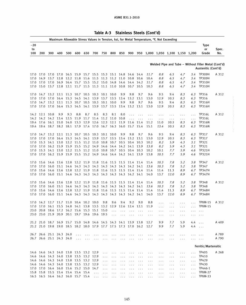
ASME B31.1-2010
Table A-3 Stainless Steels (Cont’d)
Maximum Allowable Stress Values in Tension, ksi, for Metal Temperature, °F, Not Exceeding
−20 Typeto or Spec.
100 200 300 400 500 600 650 700 750 800 850 900 950 1,000 1,050 1,100 1,150 1,200 Grade No.
Welded Pipe and Tube – Without Filler Metal (Cont’d)Austenitic (Cont’d)
17.0 17.0 17.0 17.0 16.5 15.9 15.7 15.5 15.3 15.1 14.8 14.6 14.4 11.7 8.8 6.5 4.7 3.4 TP309H A 31217.0 14.9 13.7 12.8 12.2 11.8 11.6 11.5 11.3 11.2 11.0 10.8 10.6 10.4 8.8 6.5 4.7 3.4 TP309H17.0 17.0 17.0 16.9 16.4 15.7 15.5 15.2 15.0 14.8 14.6 14.4 14.2 11.7 8.8 6.5 4.7 3.4 TP310H17.0 15.0 13.7 12.8 12.1 11.7 11.5 11.3 11.1 11.0 10.8 10.7 10.5 10.3 8.8 6.5 4.7 3.4 TP310H
17.0 14.7 13.2 12.1 11.3 10.7 10.5 10.3 10.1 10.0 9.9 9.8 9.7 9.6 9.5 9.4 8.3 6.3 TP316 A 31217.0 17.0 17.0 16.4 15.3 14.5 14.1 13.9 13.7 13.5 13.4 13.2 13.1 13.0 12.9 10.5 8.3 6.3 TP31617.0 14.7 13.2 12.1 11.3 10.7 10.5 10.3 10.1 10.0 9.9 9.8 9.7 9.6 9.5 9.4 8.3 6.3 TP316H17.0 17.0 17.0 16.4 15.3 14.5 14.1 13.9 13.7 13.5 13.4 13.2 13.1 13.0 12.9 10.5 8.3 6.3 TP316H
14.2 12.1 10.8 9.9 9.3 8.8 8.7 8.5 8.3 8.1 8.0 . . . . . . . . . . . . . . . . . . . . . TP316L A 31214.2 14.2 14.2 13.4 12.5 11.9 11.7 11.4 11.2 11.0 10.8 . . . . . . . . . . . . . . . . . . . . . TP316L19.4 17.6 16.1 15.0 14.0 13.3 12.9 12.6 12.3 12.1 11.9 11.6 11.4 11.2 11.0 10.5 8.3 6.3 TP316N19.4 19.4 18.7 18.2 18.1 17.9 17.4 17.0 16.7 16.3 16.0 15.7 15.4 15.1 13.4 10.5 8.3 6.3 TP316N
17.0 14.7 13.2 12.1 11.3 10.7 10.5 10.3 10.1 10.0 9.9 9.8 9.7 9.6 9.5 9.4 8.3 6.3 TP317 A 31217.0 17.0 17.0 16.4 15.3 14.5 14.1 13.9 13.7 13.5 13.4 13.2 13.1 13.0 12.9 10.5 8.3 6.3 TP31717.0 15.3 14.1 13.0 12.2 11.5 11.2 11.0 10.8 10.7 10.5 10.4 10.3 10.2 8.2 5.9 4.3 3.1 TP32117.0 17.0 16.2 15.9 15.9 15.5 15.2 14.9 14.6 14.4 14.2 14.1 13.9 13.8 8.2 5.9 4.3 3.1 TP32117.0 15.3 14.1 13.0 12.2 11.5 11.2 11.0 10.8 10.7 10.5 10.4 10.3 10.2 10.1 7.7 5.9 4.6 TP321H17.0 17.0 16.2 15.9 15.9 15.5 15.2 14.9 14.6 14.4 14.2 14.1 13.9 13.8 10.5 7.7 5.9 4.6 TP321H
17.0 15.6 14.6 13.6 12.8 12.2 11.9 11.8 11.6 11.5 11.5 11.4 11.4 11.4 10.3 7.8 5.2 3.8 TP347 A 31217.0 17.0 16.0 15.1 14.6 14.3 14.3 14.3 14.3 14.3 14.3 14.2 14.1 13.6 10.3 7.8 5.2 3.8 TP34717.0 15.6 14.6 13.6 12.8 12.2 11.9 11.8 11.6 11.5 11.5 11.4 11.4 11.4 11.4 11.3 8.9 6.7 TP347H17.0 17.0 16.0 15.1 14.6 14.3 14.3 14.3 14.3 14.3 14.3 14.2 14.1 14.0 13.7 12.0 8.9 6.7 TP347H
17.0 15.6 14.6 13.6 12.8 12.2 11.9 11.8 11.6 11.5 11.5 11.4 11.4 11.4 10.3 7.8 5.2 3.8 TP348 A 31217.0 17.0 16.0 15.1 14.6 14.3 14.3 14.3 14.3 14.3 14.3 14.2 14.1 13.6 10.3 7.8 5.2 3.8 TP34817.0 15.6 14.6 13.6 12.8 12.2 11.9 11.8 11.6 11.5 11.5 11.4 11.4 11.4 11.4 11.3 8.9 6.7 TP348H17.0 17.0 16.0 15.1 14.6 14.3 14.3 14.3 14.3 14.3 14.3 14.2 14.1 14.0 13.7 12.0 8.9 6.7 TP348H
17.0 14.2 12.7 11.7 11.0 10.4 10.2 10.0 9.8 9.6 9.4 9.2 9.0 8.8 . . . . . . . . . . . . TPXM-15 A 31217.0 17.0 16.1 15.5 14.8 14.1 13.8 13.5 13.2 12.9 12.6 12.4 12.1 11.9 . . . . . . . . . . . . TPXM-1523.0 20.8 18.6 17.2 16.2 15.6 15.3 15.1 15.0 . . . . . . . . . . . . . . . . . . . . . . . . . . . . . .23.0 23.0 21.9 20.9 20.1 19.7 19.6 19.6 19.5 . . . . . . . . . . . . . . . . . . . . . . . . . . . . . .
21.2 21.0 18.7 16.9 15.7 15.0 14.8 14.6 14.5 14.3 14.1 13.9 13.8 12.7 9.9 7.7 5.9 4.4 . . . A 40921.2 21.0 19.8 19.0 18.5 18.2 18.0 17.9 17.7 17.5 17.3 17.0 16.2 12.7 9.9 7.7 5.9 4.4 . . .
26.7 26.6 25.1 24.3 24.0 . . . . . . . . . . . . . . . . . . . . . . . . . . . . . . . . . . . . . . . . . . A 78926.7 26.6 25.1 24.3 24.0 . . . . . . . . . . . . . . . . . . . . . . . . . . . . . . . . . . . . . . . . . . A 790
Ferritic/Martensitic
14.6 14.6 14.3 14.0 13.8 13.5 13.2 12.9 . . . . . . . . . . . . . . . . . . . . . . . . . . . . . . TP405 A 26814.6 14.6 14.3 14.0 13.8 13.5 13.2 12.9 . . . . . . . . . . . . . . . . . . . . . . . . . . . . . . TP41014.6 14.6 14.3 14.0 13.8 13.5 13.2 12.9 . . . . . . . . . . . . . . . . . . . . . . . . . . . . . . TP42914.6 14.6 14.3 14.0 13.8 13.5 13.2 12.9 . . . . . . . . . . . . . . . . . . . . . . . . . . . . . . TP43017.0 17.0 16.4 16.0 15.6 15.2 15.0 14.7 . . . . . . . . . . . . . . . . . . . . . . . . . . . . . . TP446-115.8 15.8 15.5 15.4 15.4 15.4 15.4 . . . . . . . . . . . . . . . . . . . . . . . . . . . . . . . . . TPXM-2716.5 16.5 16.4 16.2 16.0 15.7 15.4 . . . . . . . . . . . . . . . . . . . . . . . . . . . . . . . . . TPXM-33
145
Copyright ASME International Provided by IHS under license with ASME No reproduction or networking permitted without license from IHS
--`,,```````,,```,`,`,,,,`,`,`,`-`-`,,`,,`,`,,`---

ASME B31.1-2010
Table A-3 Stainless Steels (Cont’d)
Specified SpecifiedUNS Minimum Minimum E
Spec. Type or Alloy Nominal P- Tensile, Yield, orNo. Grade Class No. Composition No. Notes ksi ksi F
Welded Pipe and Tube — Without Filler Metal (Cont’d)Ferritic/Martensitic (Cont’d)
A 731 TPXM-27 . . . S44627 27Cr–1Mo 10I (2) 65 40 0.85TPXM-33 . . . S44626 27Cr–1Mo–Ti 10I (2) 65 40 0.85
Ferritic/Austenitic
A 789 S31803 . . . S31803 22Cr–5.5Ni–3Mo–N 10H (1)(33)(34) 90 65 0.85S32205 . . . S32205 22Cr–5.5Ni–3Mo–N 10H (1)(33)(34) 95 70 0.85S32750 . . . S32750 25Cr–7Ni–4Mo–N 10H (1)(32)(33) 116 80 0.85
A 790 S31803 . . . S31803 22Cr–5.5Ni–3Mo–N 10H (1)(33)(34) 90 65 0.85S32205 . . . S32205 22Cr–5.5Ni–3Mo–N 10H (1)(33)(34) 90 65 0.85S32750 . . . S32750 25Cr–7Ni–4Mo–N 10H (1)(32)(33) 116 80 0.85
Welded Pipe — Filler Metal AddedAustenitic
A 358 304 1 & 3 S30400 18Cr–8Ni 8 (1)(10)(11) 75 30 1.00304 2 S30400 18Cr–8Ni 8 (1)(10)(11) 75 30 0.90304 1 & 3 S30400 18Cr–8Ni 8 (1)(9)(10)(11) 75 30 1.00304 2 S30400 18Cr–8Ni 8 (1)(9)(10)(11) 75 30 0.90
A 358 304L 1 & 3 S30403 18Cr–8Ni 8 (1) 70 25 1.00304L 2 S30403 18Cr–8Ni 8 (1) 70 25 0.90304L 1 & 3 S30403 18Cr–8Ni 8 (1)(9) 70 25 1.00304L 2 S30403 18Cr–8Ni 8 (1)(9) 70 25 0.90
A 358 304N 1 & 3 S30451 18Cr–8Ni–N 8 (1)(10) 80 35 1.00304N 2 S30451 18Cr–8Ni–N 8 (1)(10) 80 35 0.90304N 1 & 3 S30451 18Cr–8Ni–N 8 (1)(9)(10) 80 35 1.00304N 2 S30451 18Cr–8Ni–N 8 (1)(9)(10) 80 35 0.90
A 358 . . . 1 & 3 S30815 21Cr–11Ni–N 8 (1) 87 45 1.00. . . 2 S30815 21Cr–11Ni–N 8 (1) 87 45 0.90. . . 1 & 3 S30815 21Cr–11Ni–N 8 (1)(9) 87 45 1.00. . . 2 S30815 21Cr–11Ni–N 8 (1)(9) 87 45 0.90
A 358 309 1 & 3 S30900 23Cr–12Ni 8 (1)(10) 75 30 1.00309 2 S30900 23Cr–12Ni 8 (1)(10) 75 30 0.90309 1 & 3 S30900 23Cr–12Ni 8 (1)(9)(10) 75 30 1.00309 2 S30900 23Cr–12Ni 8 (1)(9)(10) 75 30 0.90
A 358 310 1 & 3 S31000 25Cr–20Ni 8 (1)(10)(14) 75 30 1.00310 2 S31000 25Cr–20Ni 8 (1)(10)(14) 75 30 0.90310 1 & 3 S31000 25Cr–20Ni 8 (1)(9)(10)(14) 75 30 1.00310 2 S31000 25Cr–20Ni 8 (1)(9)(10)(14) 75 30 0.90
A 358 310 1 & 3 S31000 25Cr–20Ni 8 (1)(10)(15) 75 30 1.00310 2 S31000 25Cr–20Ni 8 (1)(10)(15) 75 30 0.90310 1 & 3 S31000 25Cr–20Ni 8 (1)(9)(10)(15) 75 30 1.00310 2 S31000 25Cr–20Ni 8 (1)(9)(10)(15) 75 30 0.90
A 358 316 1 & 3 S31600 16Cr–12Ni–2Mo 8 (1)(10)(11) 75 30 1.00316 2 S31600 16Cr–12Ni–2Mo 8 (1)(10)(11) 75 30 0.90316 1 & 3 S31600 16Cr–12Ni–2Mo 8 (1)(9)(10)(11) 75 30 1.00316 2 S31600 16Cr–12Ni–2Mo 8 (1)(9)(10)(11) 75 30 0.90
146
Copyright ASME International Provided by IHS under license with ASME No reproduction or networking permitted without license from IHS
--`,,```````,,```,`,`,,,,`,`,`,`-`-`,,`,,`,`,,`---
标准分享网 www.bzfxw.com 免费下载

ASME B31.1-2010
Table A-3 Stainless Steels (Cont’d)
Maximum Allowable Stress Values in Tension, ksi, for Metal Temperature, °F, Not Exceeding
−20 Typeto or Spec.
100 200 300 400 500 600 650 700 750 800 850 900 950 1,000 1,050 1,100 1,150 1,200 Grade No.
Welded Pipe and Tube – Without Filler Metal (Cont’d)Ferritic/Martensitic (Cont’d)
15.8 15.8 15.5 15.4 15.4 15.4 15.4 . . . . . . . . . . . . . . . . . . . . . . . . . . . . . . . . . TPXM-27 A 73115.8 15.8 15.7 15.4 15.3 15.0 14.7 . . . . . . . . . . . . . . . . . . . . . . . . . . . . . . . . . TPXM-33
Ferritic/Austenitic
21.9 21.9 21.1 20.3 19.8 19.6 . . . . . . . . . . . . . . . . . . . . . . . . . . . . . . . . . . . . S31803 A 78923.1 23.1 22.3 21.4 20.9 20.7 . . . . . . . . . . . . . . . . . . . . . . . . . . . . . . . . . . . . S3220528.2 28.0 26.5 25.6 25.2 25.0 . . . . . . . . . . . . . . . . . . . . . . . . . . . . . . . . . . . . S32750
21.9 21.9 21.1 20.3 19.8 19.6 . . . . . . . . . . . . . . . . . . . . . . . . . . . . . . . . . . . . S31803 A 79021.9 21.9 21.1 20.3 19.8 19.6 . . . . . . . . . . . . . . . . . . . . . . . . . . . . . . . . . . . . S3220528.2 28.0 26.5 25.6 25.2 25.0 . . . . . . . . . . . . . . . . . . . . . . . . . . . . . . . . . . . . S32750
Welded Pipe – Filler Metal AddedAustenitic
20.0 16.7 15.0 13.8 12.9 12.3 12.0 11.7 11.5 11.2 11.0 10.8 10.6 10.4 10.1 9.8 7.7 6.1 304 A 35818.0 15.0 13.5 12.4 11.6 11.1 10.8 10.6 10.3 10.1 9.9 9.7 9.5 9.3 9.1 8.8 7.0 5.5 30420.0 20.0 18.9 18.3 17.5 16.6 16.2 15.8 15.5 15.2 14.9 14.6 14.3 14.0 12.4 9.8 7.7 6.1 30416.2 16.2 15.3 14.8 14.1 13.4 13.1 12.8 12.6 12.3 12.0 11.8 11.6 11.3 10.0 7.9 6.3 4.9 304
16.7 14.3 12.8 11.7 10.9 10.4 10.2 10.0 9.8 9.7 . . . . . . . . . . . . . . . . . . . . . . . . 304L A 35815.0 12.8 11.5 10.5 9.8 9.3 9.1 9.0 8.8 8.7 . . . . . . . . . . . . . . . . . . . . . . . . 304L16.7 16.7 16.7 15.8 14.7 14.0 13.7 13.5 13.3 13.0 . . . . . . . . . . . . . . . . . . . . . . . . 304L15.0 15.0 15.0 14.2 13.3 12.6 12.3 12.1 11.9 11.7 . . . . . . . . . . . . . . . . . . . . . . . . 304L
22.9 19.1 16.7 15.1 14.0 13.3 13.0 12.8 12.5 12.3 12.1 11.8 11.6 11.3 11.0 9.8 7.7 6.1 304N A 35820.6 17.2 15.0 13.5 12.6 11.9 11.7 11.5 11.3 11.1 10.9 10.6 10.4 10.2 9.9 8.8 7.0 5.5 304N22.9 22.9 21.7 20.3 18.9 17.9 17.5 17.2 16.9 16.6 16.3 16.0 15.6 15.2 12.4 9.8 7.7 6.1 304N20.6 20.6 19.6 18.3 17.0 16.1 15.8 15.5 15.2 14.9 14.7 14.4 14.0 13.7 11.2 8.8 7.0 5.5 304N
24.9 24.7 22.0 19.9 18.5 17.7 17.4 17.2 17.0 16.8 16.6 16.4 16.2 14.9 11.6 9.0 6.9 5.2 . . . A 35822.4 22.2 21.0 20.2 19.6 19.3 19.1 18.9 18.7 18.5 18.3 18.0 17.2 13.4 10.4 8.1 6.2 4.7 . . .24.9 24.7 22.0 19.9 18.5 17.7 17.4 17.2 17.0 16.8 16.6 16.4 16.2 14.9 11.6 9.0 6.9 5.2 . . .22.4 22.2 21.0 20.2 19.6 19.3 19.1 18.9 18.7 18.5 18.3 18.0 17.2 13.4 10.4 8.1 6.2 4.7 . . .
20.0 17.5 16.1 15.1 14.4 13.9 13.7 13.5 13.3 13.1 12.9 12.7 12.5 9.9 7.1 5.0 3.6 2.5 309 A 35818.0 15.8 14.5 13.6 13.0 12.5 12.3 12.1 12.0 11.8 11.6 11.5 11.3 8.9 6.4 4.5 3.2 2.3 30920.0 20.0 20.0 20.0 19.4 18.8 18.5 18.2 18.0 17.7 17.5 17.2 15.9 9.9 7.1 5.0 3.6 2.5 30918.0 18.0 18.0 18.0 17.5 16.9 16.6 16.4 16.2 15.9 15.7 15.5 14.3 8.9 6.4 4.5 3.2 2.3 309
20.0 17.6 16.1 15.1 14.3 13.7 13.5 13.3 13.1 12.9 12.7 12.5 12.3 9.9 7.1 5.0 3.6 2.5 310 A 35818.0 15.9 14.5 13.6 12.9 12.4 12.1 12.0 11.8 11.6 11.5 11.3 11.1 8.9 6.4 4.5 3.2 2.3 31020.0 20.0 20.0 19.9 19.3 18.5 18.2 17.9 17.7 17.4 17.2 16.9 15.9 9.9 7.1 5.0 3.6 2.5 31018.0 18.0 18.0 17.9 17.4 16.7 16.4 16.1 15.9 15.7 15.5 15.2 14.3 8.9 6.4 4.5 3.2 2.3 310
20.0 17.6 16.1 15.1 14.3 13.7 13.5 13.3 13.1 12.9 12.7 12.5 12.3 9.9 7.1 5.0 3.6 2.5 310 A 35818.0 15.9 14.5 13.6 12.9 12.4 12.1 12.0 11.8 11.6 11.5 11.3 11.1 8.9 6.4 4.5 3.2 2.3 31020.0 20.0 20.0 19.9 19.3 18.5 18.2 17.9 17.7 17.4 17.2 16.9 15.9 9.9 7.1 5.0 3.6 2.5 31018.0 18.0 18.0 17.9 17.4 16.7 16.4 16.1 15.9 15.7 15.5 15.2 14.3 8.9 6.4 4.5 3.2 2.3 310
20.0 17.3 15.6 14.3 13.3 12.6 12.3 12.1 11.9 11.8 11.6 11.5 11.4 11.3 11.2 11.1 9.8 7.4 316 A 35818.0 15.5 14.0 12.9 12.0 11.3 11.1 10.9 10.7 10.6 10.5 10.4 10.3 10.2 10.1 9.9 8.8 6.7 31620.0 20.0 20.0 19.3 18.0 17.0 16.6 16.3 16.1 15.9 15.7 15.6 15.4 15.3 15.1 12.4 9.8 7.4 31618.0 18.0 18.0 17.4 16.2 15.3 15.0 14.7 14.5 14.3 14.1 14.0 13.9 13.8 13.6 11.2 8.8 6.7 316
147
Copyright ASME International Provided by IHS under license with ASME No reproduction or networking permitted without license from IHS
--`,,```````,,```,`,`,,,,`,`,`,`-`-`,,`,,`,`,,`---

ASME B31.1-2010
Table A-3 Stainless Steels (Cont’d)
Specified SpecifiedUNS Minimum Minimum E
Spec. Type or Alloy Nominal P- Tensile, Yield, orNo. Grade Class No. Composition No. Notes ksi ksi F
Welded Pipe — Filler Metal Added (Cont’d)Austenitic (Cont’d)
A 358 316L 1 & 3 S31603 16Cr–12Ni–2Mo 8 (1) 70 25 1.00316L 2 S31603 16Cr–12Ni–2Mo 8 (1) 70 25 0.90316L 1 & 3 S31603 16Cr–12Ni–2Mo 8 (1)(9) 70 25 1.00316L 2 S31603 16Cr–12Ni–2Mo 8 (1)(9) 70 25 0.90
A 358 316N 1 & 3 S31651 16Cr–12Ni–2Mo–N 8 (1)(10) 80 35 1.00316N 2 S31651 16Cr–12Ni–2Mo–N 8 (1)(10) 80 35 0.90316N 1 & 3 S31651 16Cr–12Ni–2Mo–N 8 (1)(9)(10) 80 35 1.00316N 2 S31651 16Cr–12Ni–2Mo–N 8 (1)(9)(10) 80 35 0.90
A 358 321 1 & 3 S32100 18Cr–10Ni–Ti 8 (1)(10)(11) 75 30 1.00321 2 S32100 18Cr–10Ni–Ti 8 (1)(10)(11) 75 30 0.90321 1 & 3 S32100 18Cr–10Ni–Ti 8 (1)(9)(10)(11) 75 30 1.00321 2 S32100 18Cr–10Ni–Ti 8 (1)(9)(10)(11) 75 30 0.90
A 358 347 1 & 3 S34700 18Cr–10Ni–Cb 8 (1)(10)(11) 75 30 1.00347 2 S34700 18Cr–10Ni–Cb 8 (1)(10)(11) 75 30 0.90347 1 & 3 S34700 18Cr–10Ni–Cb 8 (1)(9)(10)(11) 75 30 1.00347 2 S34700 18Cr–10Ni–Cb 8 (1)(9)(10)(11) 75 30 0.90
A 358 348 1 & 3 S34800 18Cr–10Ni–Cb 8 (1)(10)(11) 75 30 1.00348 2 S34800 18Cr–10Ni–Cb 8 (1)(10)(11) 75 30 0.90348 1 & 3 S34800 18Cr–10Ni–Cb 8 (1)(9)(10)(11) 75 30 1.00348 2 S34800 18Cr–10Ni–Cb 8 (1)(9)(10)(11) 75 30 0.90
A 358 . . . 1 & 3 S31254 20Cr–18Ni–6Mo 8 (1) 95 45 1.00. . . 2 S31254 20Cr–18Ni–6Mo 8 (1) 95 45 0.90. . . 1 & 3 S31254 20Cr–18Ni–6Mo 8 (1)(9) 95 45 1.00. . . 2 S31254 20Cr–18Ni–6Mo 8 (1)(9) 95 45 0.90
A 358 . . . 1 & 3 S31254 20Cr–18Ni–6Mo 8 (1) 100 45 1.00. . . 2 S31254 20Cr–18Ni–6Mo 8 (1) 100 45 0.90. . . 1 & 3 S31254 20Cr–18Ni–6Mo 8 (1)(9) 100 45 1.00. . . 2 S31254 20Cr–18Ni–6Mo 8 (1)(9) 100 45 0.90
A 409 TP304 . . . S30400 18Cr–8Ni 8 (1)(10)(29) 75 30 1.00TP304 . . . S30400 18Cr–8Ni 8 (1)(10)(30) 75 30 0.90TP304 . . . S30400 18Cr–8Ni 8 (1)(10)(31) 75 30 0.80TP304 . . . S30400 18Cr–8Ni 8 (1)(9)(10)(29) 75 30 1.00TP304 . . . S30400 18Cr–8Ni 8 (1)(9)(10)(30) 75 30 0.90TP304 . . . S30400 18Cr–8Ni 8 (1)(9)(10)(31) 75 30 0.80
A 409 TP304L . . . S30403 18Cr–8Ni 8 (1)(29) 70 25 1.00TP304L . . . S30403 18Cr–8Ni 8 (1)(30) 70 25 0.90TP304L . . . S30403 18Cr–8Ni 8 (1)(31) 70 25 0.80TP304L . . . S30403 18Cr–8Ni 8 (1)(9)(29) 70 25 1.00TP304L . . . S30403 18Cr–8Ni 8 (1)(9)(30) 70 25 0.90TP304L . . . S30403 18Cr–8Ni 8 (1)(9)(31) 70 25 0.80
A 409 . . . . . . S30815 21Cr–11Ni–N 8 (1)(29) 87 45 1.00. . . . . . S30815 21Cr–11Ni–N 8 (1)(30) 87 45 0.90. . . . . . S30815 21Cr–11Ni–N 8 (1)(31) 87 45 0.80. . . . . . S30815 21Cr–11Ni–N 8 (1)(9)(29) 87 45 1.00. . . . . . S30815 21Cr–11Ni–N 8 (1)(9)(30) 87 45 0.90. . . . . . S30815 21Cr–11Ni–N 8 (1)(9)(31) 87 45 0.80
148
Copyright ASME International Provided by IHS under license with ASME No reproduction or networking permitted without license from IHS
--`,,```````,,```,`,`,,,,`,`,`,`-`-`,,`,,`,`,,`---
标准分享网 www.bzfxw.com 免费下载
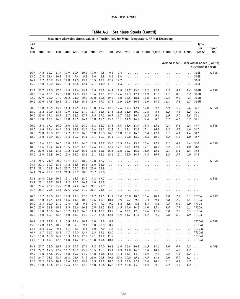
ASME B31.1-2010
Table A-3 Stainless Steels (Cont’d)
Maximum Allowable Stress Values in Tension, ksi, for Metal Temperature, °F, Not Exceeding
−20 Typeto or Spec.
100 200 300 400 500 600 650 700 750 800 850 900 950 1,000 1,050 1,100 1,150 1,200 Grade No.
Welded Pipe – Filler Metal Added (Cont’d)Austenitic (Cont’d)
16.7 14.2 12.7 11.7 10.9 10.4 10.2 10.0 9.8 9.6 9.4 . . . . . . . . . . . . . . . . . . . . . 316L A 35815.0 12.8 11.4 10.5 9.8 9.4 9.2 9.0 8.8 8.6 8.4 . . . . . . . . . . . . . . . . . . . . . 316L16.7 16.7 16.7 15.7 14.8 14.0 13.7 13.5 13.2 12.9 12.7 . . . . . . . . . . . . . . . . . . . . . 316L15.0 15.0 15.0 14.2 13.3 12.6 12.4 12.1 11.9 11.6 11.4 . . . . . . . . . . . . . . . . . . . . . 316L
22.9 20.7 19.0 17.6 16.5 15.6 15.2 14.9 14.5 14.2 13.9 13.7 13.4 13.2 12.9 12.3 9.8 7.4 316N A 35820.6 18.6 17.1 15.8 14.8 14.0 13.7 13.4 13.1 12.8 12.6 12.3 12.1 11.9 11.6 11.1 8.8 6.7 316N22.9 22.9 22.0 21.5 21.2 21.0 20.5 20.0 19.6 19.2 18.8 18.5 18.1 17.8 15.8 12.3 9.8 7.4 316N20.6 20.6 19.8 19.3 19.1 18.9 18.5 18.0 17.7 17.3 16.9 16.6 16.3 16.0 14.2 11.1 8.8 6.7 316N
20.0 18.0 16.5 15.3 14.3 13.5 13.2 13.0 12.7 12.6 12.4 12.3 12.1 12.0 9.6 6.9 5.0 3.6 321 A 35818.0 16.2 14.9 13.8 12.9 12.2 11.9 11.7 11.5 11.3 11.2 11.0 10.9 10.8 8.6 6.2 4.5 3.2 32120.0 20.0 19.1 18.7 18.7 18.3 17.9 17.5 17.2 16.9 16.7 16.5 16.4 16.2 9.6 6.9 5.0 3.6 32118.0 18.0 17.2 16.8 16.8 16.5 16.1 15.8 15.5 15.3 15.1 14.9 14.7 14.6 8.6 6.2 4.5 3.2 321
20.0 18.4 17.1 16.0 15.0 14.3 14.0 13.8 13.7 13.6 13.5 13.4 13.4 13.4 12.1 9.1 6.1 4.4 347 A 35818.0 16.6 15.4 14.4 13.5 12.9 12.6 12.4 12.3 12.2 12.1 12.1 12.1 12.1 10.9 8.2 5.5 4.0 34720.0 20.0 18.8 17.8 17.2 16.9 16.8 16.8 16.8 16.8 16.8 16.7 16.6 16.0 12.1 9.1 6.1 4.4 34718.0 18.0 16.9 16.0 15.4 15.2 15.1 15.1 15.1 15.1 15.1 15.0 14.9 14.4 10.9 8.2 5.5 4.0 347
20.0 18.4 17.1 16.0 15.0 14.3 14.0 13.8 13.7 13.6 13.5 13.4 13.4 13.4 12.1 9.1 6.1 4.4 348 A 35818.0 16.6 15.4 14.4 13.5 12.9 12.6 12.4 12.3 12.2 12.1 12.1 12.1 12.1 10.9 8.2 5.5 4.0 34820.0 20.0 18.8 17.8 17.2 16.9 16.8 16.8 16.8 16.8 16.8 16.7 16.6 16.0 12.1 9.1 6.1 4.4 34818.0 18.0 16.9 16.0 15.4 15.2 15.1 15.1 15.1 15.1 15.1 15.0 14.9 14.4 10.9 8.2 5.5 4.0 348
27.1 24.5 21.9 20.2 19.1 18.3 18.0 17.8 17.7 . . . . . . . . . . . . . . . . . . . . . . . . . . . . . . A 35824.4 22.1 19.7 18.2 17.2 16.5 16.2 16.0 15.9 . . . . . . . . . . . . . . . . . . . . . . . . . . . . . .27.1 27.1 25.8 24.6 23.7 23.2 23.1 23.0 22.9 . . . . . . . . . . . . . . . . . . . . . . . . . . . . . .24.4 24.4 23.2 22.1 21.3 20.9 20.8 20.7 20.6 . . . . . . . . . . . . . . . . . . . . . . . . . . . . . .
28.6 24.5 21.9 20.2 19.1 18.3 18.0 17.8 17.7 . . . . . . . . . . . . . . . . . . . . . . . . . . . . . . A 35825.7 22.1 19.7 18.2 17.2 16.5 16.2 16.0 15.9 . . . . . . . . . . . . . . . . . . . . . . . . . . . . . .28.6 28.6 27.2 25.9 25.0 24.4 24.3 24.1 23.9 . . . . . . . . . . . . . . . . . . . . . . . . . . . . . .25.7 25.7 24.5 23.3 22.5 22.0 21.9 21.7 21.5 . . . . . . . . . . . . . . . . . . . . . . . . . . . . . .
20.0 16.7 15.0 13.8 12.9 12.3 12.0 11.7 11.5 11.2 11.0 10.8 10.6 10.4 10.1 9.8 7.7 6.1 TP304 A 40918.0 15.0 13.5 12.4 11.6 11.1 10.8 10.6 10.3 10.1 9.9 9.7 9.5 9.3 9.1 8.8 7.0 5.5 TP30416.0 13.3 12.0 11.0 10.4 9.8 9.6 9.4 9.2 9.0 8.8 8.6 8.5 8.3 8.1 7.8 6.2 4.9 TP30420.0 20.0 18.9 18.3 17.5 16.6 16.2 15.8 15.5 15.2 14.9 14.6 14.3 14.0 12.4 9.8 7.7 6.1 TP30418.0 18.0 17.0 16.5 15.7 14.9 14.6 14.3 13.9 13.7 13.4 13.1 12.8 12.6 11.2 8.8 7.0 5.5 TP30416.0 16.0 15.1 14.6 14.0 13.3 13.0 12.7 12.4 12.1 11.9 11.7 11.4 11.2 9.9 7.8 6.2 4.9 TP304
16.7 14.3 12.8 11.7 10.9 10.4 10.2 10.0 9.8 9.7 . . . . . . . . . . . . . . . . . . . . . . . . TP304L A 40915.0 12.8 11.5 10.5 9.8 9.3 9.1 9.0 8.8 8.7 . . . . . . . . . . . . . . . . . . . . . . . . TP304L13.3 11.4 10.2 9.4 8.7 8.3 8.1 8.0 7.9 7.7 . . . . . . . . . . . . . . . . . . . . . . . . TP304L16.7 16.7 16.7 15.8 14.7 14.0 13.7 13.5 13.3 13.0 . . . . . . . . . . . . . . . . . . . . . . . . TP304L15.0 15.0 15.0 14.2 13.3 12.6 12.3 12.1 11.9 11.7 . . . . . . . . . . . . . . . . . . . . . . . . TP304L13.3 13.3 13.3 12.6 11.8 11.2 11.0 10.8 10.6 10.4 . . . . . . . . . . . . . . . . . . . . . . . . TP304L
24.9 24.7 22.0 19.9 18.5 17.7 17.4 17.2 17.0 16.8 16.6 16.4 16.2 14.9 11.6 9.0 6.9 5.2 . . . A 40922.4 22.2 19.8 17.9 16.7 15.9 15.7 15.5 15.3 15.1 14.9 14.8 14.6 13.4 10.4 8.1 6.2 4.7 . . .19.9 19.8 17.6 15.9 14.8 14.2 13.9 13.8 13.6 13.4 13.3 13.1 13.0 11.9 9.3 7.2 5.5 4.2 . . .24.9 24.7 23.3 22.4 21.8 21.4 21.2 21.0 20.8 20.6 20.3 20.0 19.1 14.9 11.6 9.0 6.9 5.2 . . .22.4 22.2 21.0 20.2 19.6 19.3 19.1 18.9 18.7 18.5 18.3 18.0 17.2 13.4 10.4 8.1 6.2 4.7 . . .19.9 19.8 18.6 17.9 17.4 17.1 17.0 16.8 16.6 16.5 16.2 16.0 15.3 11.9 9.3 7.2 5.5 4.2 . . .
149
Copyright ASME International Provided by IHS under license with ASME No reproduction or networking permitted without license from IHS
--`,,```````,,```,`,`,,,,`,`,`,`-`-`,,`,,`,`,,`---

ASME B31.1-2010
Table A-3 Stainless Steels (Cont’d)
Specified SpecifiedUNS Minimum Minimum E
Spec. Type or Alloy Nominal P- Tensile, Yield, orNo. Grade Class No. Composition No. Notes ksi ksi F
Welded Pipe — Filler Metal Added (Cont’d)Austenitic (Cont’d)
A 409 TP316 . . . S31600 16Cr–12Ni–2Mo 8 (1)(10)(29) 75 30 1.00TP316 . . . S31600 16Cr–12Ni–2Mo 8 (1)(10)(30) 75 30 0.90TP316 . . . S31600 16Cr–12Ni–2Mo 8 (1)(10)(31) 75 30 0.80TP316 . . . S31600 16Cr–12Ni–2Mo 8 (1)(9)(10)(29) 75 30 1.00TP316 . . . S31600 16Cr–12Ni–2Mo 8 (1)(9)(10)(30) 75 30 0.90TP316 . . . S31600 16Cr–12Ni–2Mo 8 (1)(9)(10)(31) 75 30 0.80
A 409 TP316L . . . S31603 16Cr–12Ni–2Mo 8 (1)(29) 70 25 1.00TP316L . . . S31603 16Cr–12Ni–2Mo 8 (1)(30) 70 25 0.90TP316L . . . S31603 16Cr–12Ni–2Mo 8 (1)(31) 70 25 0.80TP316L . . . S31603 16Cr–12Ni–2Mo 8 (1)(9)(29) 70 25 1.00TP316L . . . S31603 16Cr–12Ni–2Mo 8 (1)(9)(30) 70 25 0.90TP316L . . . S31603 16Cr–12Ni–2Mo 8 (1)(9)(31) 70 25 0.80
Ferritic/Austenitic
A 928 S31803 1 & 3 S31803 22Cr–5.5Ni–3Mo–N 10H (1)(33)(34) 90 65 1.00S31803 2 S31803 22Cr–5.5Ni–3Mo–N 10H (1)(33)(34) 90 65 0.90
Plate, Sheet, and StripAustenitic
A 240 304 . . . S30400 18Cr–8Ni 8 (10)(11) 75 30 1.00304 . . . S30400 18Cr–8Ni 8 (9)(10)(11) 75 30 1.00304L . . . S30403 18Cr–8Ni 8 (1) 70 25 1.00304L . . . S30403 18Cr–8Ni 8 (1)(9) 70 25 1.00304N . . . S30451 18Cr–8Ni–N 8 (1)(10) 80 35 1.00304N . . . S30451 18Cr–8Ni–N 8 (1)(9)(10) 80 35 1.00
A 240 . . . . . . S30815 21Cr–11Ni–N 8 (1) 87 45 1.00. . . . . . S30815 21Cr–11Ni–N 8 (1)(9) 87 45 1.00
A 240 309H . . . S30909 23Cr–12Ni 8 (9)(11)(27) 75 30 1.00309H . . . S30909 23Cr–12Ni 8 (11)(27) 75 30 1.00309S . . . S30908 23Cr–12Ni 8 (1)(10) 75 30 1.00309S . . . S30908 23Cr–12Ni 8 (1)(9)(10) 75 30 1.00
A 240 310H . . . S31009 25Cr–20Ni 8 (9) 75 30 1.00310H . . . S31009 25Cr–20Ni 8 . . . 75 30 1.00310S . . . S31008 25Cr–20Ni 8 (10)(11)(14) 75 30 1.00310S . . . S31008 25Cr–20Ni 8 (9)(10)(11)(14) 75 30 1.00310S . . . S31008 25Cr–20Ni 8 (10)(11)(15) 75 30 1.00310S . . . S31008 25Cr–20Ni 8 (9)(10)(11)(15) 75 30 1.00
A 240 316 . . . S31600 16Cr–12Ni–2Mo 8 (10)(11) 75 30 1.00316 . . . S31600 16Cr–12Ni–2Mo 8 (9)(10)(11) 75 30 1.00316L . . . S31603 16Cr–12Ni–2Mo 8 (1) 70 25 1.00316L . . . S31603 16Cr–12Ni–2Mo 8 (1)(9) 70 25 1.00316N . . . S31651 16Cr–12Ni–2Mo–N 8 (10) 80 35 1.00316N . . . S31651 16Cr–12Ni–2Mo–N 8 (9)(10) 80 35 1.00
150
Copyright ASME International Provided by IHS under license with ASME No reproduction or networking permitted without license from IHS
--`,,```````,,```,`,`,,,,`,`,`,`-`-`,,`,,`,`,,`---
标准分享网 www.bzfxw.com 免费下载

ASME B31.1-2010
Table A-3 Stainless Steels (Cont’d)
Maximum Allowable Stress Values in Tension, ksi, for Metal Temperature, °F, Not Exceeding
−20 Typeto or Spec.
100 200 300 400 500 600 650 700 750 800 850 900 950 1,000 1,050 1,100 1,150 1,200 Grade No.
Welded Pipe – Filler Metal Added (Cont’d)Austenitic (Cont’d)
20.0 17.3 15.6 14.3 13.3 12.6 12.3 12.1 11.9 11.8 11.6 11.5 11.4 11.3 11.2 11.1 9.8 7.4 TP316 A 40918.0 15.5 14.0 12.9 12.0 11.3 11.1 10.9 10.7 10.6 10.5 10.4 10.3 10.2 10.1 9.9 8.8 6.7 TP31616.0 13.8 12.5 11.4 10.6 10.1 9.9 9.7 9.5 9.4 9.3 9.2 9.1 9.1 9.0 8.8 7.8 5.9 TP31620.0 20.0 20.0 19.3 18.0 17.0 16.6 16.3 16.1 15.9 15.7 15.6 15.4 15.3 15.1 12.4 9.8 7.4 TP31618.0 18.0 18.0 17.4 16.2 15.3 15.0 14.7 14.5 14.3 14.1 14.0 13.9 13.8 13.6 11.2 8.8 6.7 TP31616.0 16.0 16.0 15.4 14.4 13.6 13.3 13.1 12.9 12.7 12.6 12.5 12.3 12.2 12.1 9.9 7.8 5.9 TP316
16.7 14.2 12.7 11.7 10.9 10.4 10.2 10.0 9.8 9.6 9.4 . . . . . . . . . . . . . . . . . . . . . TP316L A 40915.0 12.8 11.4 10.5 9.8 9.4 9.2 9.0 8.8 8.6 8.4 . . . . . . . . . . . . . . . . . . . . . TP316L13.3 11.4 10.2 9.3 8.7 8.3 8.1 8.0 7.8 7.7 7.5 . . . . . . . . . . . . . . . . . . . . . TP316L16.7 16.7 16.7 15.7 14.8 14.0 13.7 13.5 13.2 12.9 12.7 . . . . . . . . . . . . . . . . . . . . . TP316L15.0 15.0 15.0 14.2 13.3 12.6 12.4 12.1 11.9 11.6 11.4 . . . . . . . . . . . . . . . . . . . . . TP316L13.3 13.3 13.3 12.6 11.8 11.2 11.0 10.8 10.6 10.3 10.1 . . . . . . . . . . . . . . . . . . . . . TP316L
Ferritic/Austenitic
25.7 25.7 24.8 23.9 23.3 23.1 . . . . . . . . . . . . . . . . . . . . . . . . . . . . . . . . . . . . S31803 A 92823.1 23.1 22.3 21.5 21.0 20.8 . . . . . . . . . . . . . . . . . . . . . . . . . . . . . . . . . . . . S31803
Plate, Sheet, and StripAustenitic
20.0 16.7 15.0 13.8 12.9 12.3 12.0 11.7 11.5 11.2 11.0 10.8 10.6 10.4 10.1 9.8 7.7 6.1 304 A 24020.0 20.0 18.9 18.3 17.5 16.6 16.2 15.8 15.5 15.2 14.9 14.6 14.3 14.0 12.4 9.8 7.7 6.1 30416.7 14.3 12.8 11.7 10.9 10.4 10.2 10.0 9.8 9.7 . . . . . . . . . . . . . . . . . . . . . . . . 304L16.7 16.7 16.7 15.8 14.7 14.0 13.7 13.5 13.3 13.0 . . . . . . . . . . . . . . . . . . . . . . . . 304L22.9 19.1 16.7 15.1 14.0 13.3 13.0 12.8 12.5 12.3 12.1 11.8 11.6 11.3 11.0 9.8 7.7 6.1 304N22.9 22.9 21.7 20.3 18.9 17.9 17.5 17.2 16.9 16.6 16.3 16.0 15.6 15.2 12.4 9.8 7.7 6.1 304N
24.9 24.7 22.0 19.9 18.5 17.7 17.4 17.2 17.0 16.8 16.6 16.4 16.2 14.9 11.6 9.0 6.9 5.2 . . . A 24024.9 24.7 23.3 22.4 21.8 21.4 21.2 21.0 20.8 20.6 20.3 20.0 19.1 14.9 11.6 9.0 6.9 5.2 . . .
20.0 20.0 20.0 20.0 19.4 18.8 18.5 18.2 18.0 17.7 17.5 17.2 16.9 13.8 10.3 7.6 5.5 4.0 309H A 24020.0 17.5 16.1 15.1 14.4 13.9 13.7 13.5 13.3 13.1 12.9 12.7 12.5 12.3 10.3 7.6 5.5 4.0 309H20.0 17.5 16.1 15.1 14.4 13.9 13.7 13.5 13.3 13.1 12.9 12.7 12.5 9.9 7.1 5.0 3.6 2.5 309S20.0 20.0 20.0 20.0 19.4 18.8 18.5 18.2 18.0 17.7 17.5 17.2 15.9 9.9 7.1 5.0 3.6 2.5 309S
20.0 20.0 20.0 19.9 19.3 18.5 18.2 17.9 17.7 17.4 17.2 16.9 16.7 13.8 10.3 7.6 5.5 4.0 310H A 24020.0 17.6 16.1 15.1 14.3 13.7 13.5 13.3 13.1 12.9 12.7 12.5 12.3 12.1 10.3 7.6 5.5 4.0 310H20.0 17.6 16.1 15.1 14.3 13.7 13.5 13.3 13.1 12.9 12.7 12.5 12.3 9.9 7.1 5.0 3.6 2.5 310S20.0 20.0 20.0 19.9 19.3 18.5 18.2 17.9 17.7 17.4 17.2 16.9 15.9 9.9 7.1 5.0 3.6 2.5 310S20.0 17.6 16.1 15.1 14.3 13.7 13.5 13.3 13.1 12.9 12.7 12.5 12.3 9.9 7.1 5.0 3.6 2.5 310S20.0 20.0 20.0 19.9 19.3 18.5 18.2 17.9 17.7 17.4 17.2 16.9 15.9 9.9 7.1 5.0 3.6 2.5 310S
20.0 17.3 15.6 14.3 13.3 12.6 12.3 12.1 11.9 11.8 11.6 11.5 11.4 11.3 11.2 11.1 9.8 7.4 316 A 24020.0 20.0 20.0 19.3 18.0 17.0 16.6 16.3 16.1 15.9 15.7 15.6 15.4 15.3 15.1 12.4 9.8 7.4 31616.7 14.2 12.7 11.7 10.9 10.4 10.2 10.0 9.8 9.6 9.4 9.2 9.0 8.8 8.6 8.4 8.3 6.4 316L16.7 16.7 16.7 15.7 14.8 14.0 13.7 13.5 13.2 12.9 12.7 12.4 12.1 11.8 10.8 10.2 8.8 6.4 316L22.9 20.7 19.0 17.6 16.5 15.6 15.2 14.9 14.5 14.2 13.9 13.7 13.4 13.2 12.9 12.3 9.8 7.4 316N22.9 22.9 22.0 21.5 21.2 21.0 20.5 20.0 19.6 19.2 18.8 18.5 18.1 17.8 15.8 12.3 9.8 7.4 316N
151
Copyright ASME International Provided by IHS under license with ASME No reproduction or networking permitted without license from IHS
--`,,```````,,```,`,`,,,,`,`,`,`-`-`,,`,,`,`,,`---
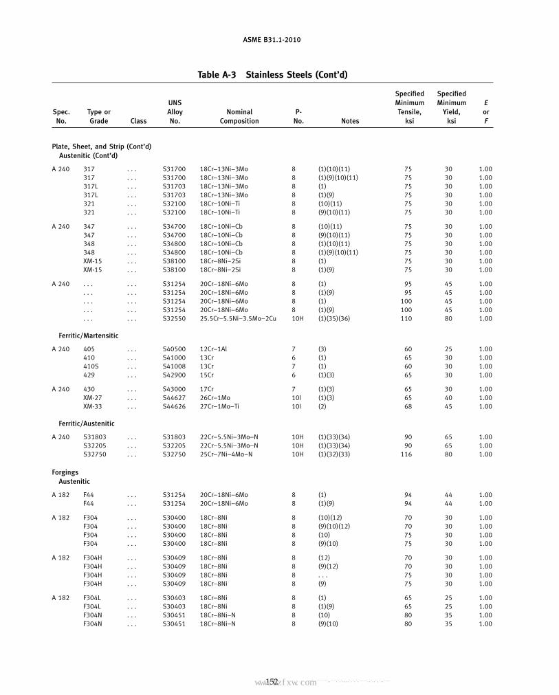
ASME B31.1-2010
Table A-3 Stainless Steels (Cont’d)
Specified SpecifiedUNS Minimum Minimum E
Spec. Type or Alloy Nominal P- Tensile, Yield, orNo. Grade Class No. Composition No. Notes ksi ksi F
Plate, Sheet, and Strip (Cont’d)Austenitic (Cont’d)
A 240 317 . . . S31700 18Cr–13Ni–3Mo 8 (1)(10)(11) 75 30 1.00317 . . . S31700 18Cr–13Ni–3Mo 8 (1)(9)(10)(11) 75 30 1.00317L . . . S31703 18Cr–13Ni–3Mo 8 (1) 75 30 1.00317L . . . S31703 18Cr–13Ni–3Mo 8 (1)(9) 75 30 1.00321 . . . S32100 18Cr–10Ni–Ti 8 (10)(11) 75 30 1.00321 . . . S32100 18Cr–10Ni–Ti 8 (9)(10)(11) 75 30 1.00
A 240 347 . . . S34700 18Cr–10Ni–Cb 8 (10)(11) 75 30 1.00347 . . . S34700 18Cr–10Ni–Cb 8 (9)(10)(11) 75 30 1.00348 . . . S34800 18Cr–10Ni–Cb 8 (1)(10)(11) 75 30 1.00348 . . . S34800 18Cr–10Ni–Cb 8 (1)(9)(10)(11) 75 30 1.00XM-15 . . . S38100 18Cr–8Ni–2Si 8 (1) 75 30 1.00XM-15 . . . S38100 18Cr–8Ni–2Si 8 (1)(9) 75 30 1.00
A 240 . . . . . . S31254 20Cr–18Ni–6Mo 8 (1) 95 45 1.00. . . . . . S31254 20Cr–18Ni–6Mo 8 (1)(9) 95 45 1.00. . . . . . S31254 20Cr–18Ni–6Mo 8 (1) 100 45 1.00. . . . . . S31254 20Cr–18Ni–6Mo 8 (1)(9) 100 45 1.00. . . . . . S32550 25.5Cr–5.5Ni–3.5Mo–2Cu 10H (1)(35)(36) 110 80 1.00
Ferritic/Martensitic
A 240 405 . . . S40500 12Cr–1Al 7 (3) 60 25 1.00410 . . . S41000 13Cr 6 (1) 65 30 1.00410S . . . S41008 13Cr 7 (1) 60 30 1.00429 . . . S42900 15Cr 6 (1)(3) 65 30 1.00
A 240 430 . . . S43000 17Cr 7 (1)(3) 65 30 1.00XM-27 . . . S44627 26Cr–1Mo 10I (1)(3) 65 40 1.00XM-33 . . . S44626 27Cr–1Mo–Ti 10I (2) 68 45 1.00
Ferritic/Austenitic
A 240 S31803 . . . S31803 22Cr–5.5Ni–3Mo–N 10H (1)(33)(34) 90 65 1.00S32205 . . . S32205 22Cr–5.5Ni–3Mo–N 10H (1)(33)(34) 90 65 1.00S32750 . . . S32750 25Cr–7Ni–4Mo–N 10H (1)(32)(33) 116 80 1.00
ForgingsAustenitic
A 182 F44 . . . S31254 20Cr–18Ni–6Mo 8 (1) 94 44 1.00F44 . . . S31254 20Cr–18Ni–6Mo 8 (1)(9) 94 44 1.00
A 182 F304 . . . S30400 18Cr–8Ni 8 (10)(12) 70 30 1.00F304 . . . S30400 18Cr–8Ni 8 (9)(10)(12) 70 30 1.00F304 . . . S30400 18Cr–8Ni 8 (10) 75 30 1.00F304 . . . S30400 18Cr–8Ni 8 (9)(10) 75 30 1.00
A 182 F304H . . . S30409 18Cr–8Ni 8 (12) 70 30 1.00F304H . . . S30409 18Cr–8Ni 8 (9)(12) 70 30 1.00F304H . . . S30409 18Cr–8Ni 8 . . . 75 30 1.00F304H . . . S30409 18Cr–8Ni 8 (9) 75 30 1.00
A 182 F304L . . . S30403 18Cr–8Ni 8 (1) 65 25 1.00F304L . . . S30403 18Cr–8Ni 8 (1)(9) 65 25 1.00F304N . . . S30451 18Cr–8Ni–N 8 (10) 80 35 1.00F304N . . . S30451 18Cr–8Ni–N 8 (9)(10) 80 35 1.00
152
Copyright ASME International Provided by IHS under license with ASME No reproduction or networking permitted without license from IHS
--`,,```````,,```,`,`,,,,`,`,`,`-`-`,,`,,`,`,,`---标准分享网 www.bzfxw.com 免费下载

ASME B31.1-2010
Table A-3 Stainless Steels (Cont’d)
Maximum Allowable Stress Values in Tension, ksi, for Metal Temperature, °F, Not Exceeding
−20 Typeto or Spec.
100 200 300 400 500 600 650 700 750 800 850 900 950 1,000 1,050 1,100 1,150 1,200 Grade No.
Plate, Sheet, and Strip (Cont’d)Austenitic (Cont’d)
20.0 17.3 15.6 14.3 13.3 12.6 12.3 12.1 11.9 11.8 11.6 11.5 11.4 11.3 11.2 11.1 9.8 7.4 317 A 24020.0 20.0 20.0 19.3 18.0 17.0 16.6 16.3 16.1 15.9 15.7 15.6 15.4 15.3 15.1 12.4 9.8 7.4 31720.0 17.0 15.2 14.0 13.1 12.5 12.2 12.0 11.7 11.5 11.3 . . . . . . . . . . . . . . . . . . . . . 317L20.0 20.0 19.6 18.9 17.7 16.9 16.5 16.2 15.8 15.5 15.2 . . . . . . . . . . . . . . . . . . . . . 317L20.0 18.0 16.5 15.3 14.3 13.5 13.2 13.0 12.7 12.6 12.4 12.3 12.1 12.0 9.6 6.9 5.0 3.6 32120.0 20.0 19.1 18.7 18.7 18.3 17.9 17.5 17.2 16.9 16.7 16.5 16.4 16.2 9.6 6.9 5.0 3.6 321
20.0 18.4 17.1 16.0 15.0 14.3 14.0 13.8 13.7 13.6 13.5 13.4 13.4 13.4 12.1 9.1 6.1 4.4 347 A 24020.0 20.0 18.8 17.8 17.2 16.9 16.8 16.8 16.8 16.8 16.8 16.7 16.6 16.0 12.1 9.1 6.1 4.4 34720.0 18.4 17.1 16.0 15.0 14.3 14.0 13.8 13.7 13.6 13.5 13.4 13.4 13.4 12.1 9.1 6.1 4.4 34820.0 20.0 18.8 17.8 17.2 16.9 16.8 16.8 16.8 16.8 16.8 16.7 16.6 16.0 12.1 9.1 6.1 4.4 34820.0 16.7 15.0 13.8 12.9 12.3 12.0 11.7 11.5 11.2 11.0 10.8 10.6 10.4 . . . . . . . . . . . . XM-1520.0 20.0 18.9 18.3 17.5 16.6 16.2 15.8 15.5 15.2 14.9 14.6 14.3 14.0 . . . . . . . . . . . . XM-15
27.1 24.5 21.9 20.2 19.1 18.3 18.0 17.8 17.7 . . . . . . . . . . . . . . . . . . . . . . . . . . . . . . A 24027.1 27.1 25.8 24.6 23.7 23.2 23.1 23.0 22.9 . . . . . . . . . . . . . . . . . . . . . . . . . . . . . .28.6 24.5 21.9 20.2 19.1 18.3 18.0 17.8 17.7 . . . . . . . . . . . . . . . . . . . . . . . . . . . . . .28.6 28.6 27.2 25.9 25.0 24.4 24.3 24.1 23.9 . . . . . . . . . . . . . . . . . . . . . . . . . . . . . .31.4 31.3 29.5 28.6 28.2 . . . . . . . . . . . . . . . . . . . . . . . . . . . . . . . . . . . . . . . . . .
Ferritic/Martensitic
16.7 15.3 14.8 14.5 14.3 14.0 13.8 13.5 . . . . . . . . . . . . . . . . . . . . . . . . . . . . . . 405 A 24018.6 18.4 17.8 17.4 17.2 16.8 16.6 16.2 15.7 15.1 14.4 12.3 8.8 6.4 4.4 2.9 1.8 1.0 41017.1 17.1 16.8 16.5 16.3 15.9 15.6 15.2 14.7 14.1 13.4 12.3 8.8 6.4 4.4 2.9 1.8 1.0 410S18.6 18.4 17.8 17.4 17.2 16.8 16.6 16.2 15.7 15.1 14.4 12.0 9.2 6.5 4.5 3.2 2.4 1.8 429
18.6 18.4 17.8 17.4 17.2 16.8 16.6 16.2 15.7 15.1 14.4 12.0 9.2 6.5 4.5 3.2 2.4 1.8 430 A 24018.6 18.6 18.3 18.1 18.1 18.1 18.1 . . . . . . . . . . . . . . . . . . . . . . . . . . . . . . . . . XM-2719.4 19.4 19.3 19.0 18.8 18.4 18.1 . . . . . . . . . . . . . . . . . . . . . . . . . . . . . . . . . XM-33
Ferritic/Austenitic
25.7 25.7 24.8 23.9 23.3 23.1 . . . . . . . . . . . . . . . . . . . . . . . . . . . . . . . . . . . . S31803 A 24025.7 25.7 24.8 23.9 23.3 23.1 . . . . . . . . . . . . . . . . . . . . . . . . . . . . . . . . . . . . S3220533.1 33.0 31.2 30.1 29.6 29.4 . . . . . . . . . . . . . . . . . . . . . . . . . . . . . . . . . . . . S32750
ForgingsAustenitic
26.9 23.9 21.4 19.8 18.6 17.9 17.6 17.4 17.3 . . . . . . . . . . . . . . . . . . . . . . . . . . . F44 A 18226.9 26.9 25.5 24.3 23.5 23.0 22.8 22.7 22.6 . . . . . . . . . . . . . . . . . . . . . . . . . . . F44
20.0 16.7 15.0 13.8 12.9 12.3 12.0 11.7 11.5 11.2 11.0 10.8 10.6 10.4 10.1 9.8 7.7 6.1 F304 A 18220.0 20.0 18.9 18.3 17.5 16.6 16.2 15.8 15.5 15.2 14.9 14.6 14.3 14.0 12.4 9.8 7.7 6.1 F30420.0 16.7 15.0 13.8 12.9 12.3 12.0 11.7 11.5 11.2 11.0 10.8 10.6 10.4 10.1 9.8 7.7 6.1 F30420.0 20.0 18.9 18.3 17.5 16.6 16.2 15.8 15.5 15.2 14.9 14.6 14.3 14.0 12.4 9.8 7.7 6.1 F304
20.0 16.7 15.0 13.8 12.9 12.3 12.0 11.7 11.5 11.2 11.0 10.8 10.6 10.4 10.1 9.8 7.7 6.1 F304H A 18220.0 18.9 17.7 17.1 16.9 16.6 16.2 15.8 15.5 15.2 14.9 14.6 14.3 14.0 12.4 9.8 7.7 6.1 F304H20.0 16.7 15.0 13.8 12.9 12.3 12.0 11.7 11.5 11.2 11.0 10.8 10.6 10.4 10.1 9.8 7.7 6.1 F304H20.0 20.0 18.9 18.3 17.5 16.6 16.2 15.8 15.5 15.2 14.9 14.6 14.3 14.0 12.4 9.8 7.7 6.1 F304H
16.7 14.3 12.8 11.7 10.9 10.4 10.2 10.0 9.8 9.7 . . . . . . . . . . . . . . . . . . . . . . . . F304L A 18216.7 16.7 16.2 15.6 14.7 14.0 13.7 13.5 13.3 13.0 . . . . . . . . . . . . . . . . . . . . . . . . F304L22.9 19.1 16.7 15.1 14.0 13.3 13.0 12.8 12.5 12.3 12.1 11.8 11.6 11.3 11.0 9.8 7.7 6.1 F304N22.9 22.9 21.7 20.3 18.9 17.9 17.5 17.2 16.9 16.6 16.3 16.0 15.6 15.2 12.4 9.8 7.7 6.1 F304N
153
Copyright ASME International Provided by IHS under license with ASME No reproduction or networking permitted without license from IHS
--`,,```````,,```,`,`,,,,`,`,`,`-`-`,,`,,`,`,,`---

ASME B31.1-2010
Table A-3 Stainless Steels (Cont’d)
Specified SpecifiedUNS Minimum Minimum E
Spec. Type or Alloy Nominal P- Tensile, Yield, orNo. Grade Class No. Composition No. Notes ksi ksi F
Forgings (Cont’d)Austenitic (Cont’d)
A 182 . . . . . . S30815 21Cr–11Ni–N 8 (1) 87 45 1.00. . . . . . S30815 21Cr–11Ni–N 8 (1)(9) 87 45 1.00
A 182 F310 . . . S31000 25Cr–20Ni 8 (1)(10)(14) 75 30 1.00F310 . . . S31000 25Cr–20Ni 8 (1)(9)(10)(14) 75 30 1.00F310 . . . S31000 25Cr–20Ni 8 (1)(10)(15) 75 30 1.00F310 . . . S31000 25Cr–20Ni 8 (1)(9)(10)(15) 75 30 1.00
A 182 F316 . . . S31600 16Cr–12Ni–2Mo 8 (10)(12) 70 30 1.00F316 . . . S31600 16Cr–12Ni–2Mo 8 (9)(10)(12) 70 30 1.00F316 . . . S31600 16Cr–12Ni–2Mo 8 (10) 75 30 1.00F316 . . . S31600 16Cr–12Ni–2Mo 8 (9)(10) 75 30 1.00
A 182 F316H . . . S31609 16Cr–12Ni–2Mo 8 (12) 70 30 1.00F316H . . . S31609 16Cr–12Ni–2Mo 8 (9)(12) 70 30 1.00F316H . . . S31609 16Cr–12Ni–2Mo 8 . . . 75 30 1.00F316H . . . S31609 16Cr–12Ni–2Mo 8 (9) 75 30 1.00
A 182 F316L . . . S31603 16Cr–12Ni–2Mo 8 (1)(37) 70 25 1.00F316L . . . S31603 16Cr–12Ni–2Mo 8 (1)(9)(37) 70 25 1.00F316N . . . S31651 16Cr–12Ni–2Mo–N 8 (10) 80 35 1.00F316N . . . S31651 16Cr–12Ni–2Mo–N 8 (9)(10) 80 35 1.00
A 182 F321 . . . S32100 18Cr–10Ni–Ti 8 (12) 70 30 1.00F321 . . . S32100 18Cr–10Ni–Ti 8 (9)(12) 70 30 1.00F321 . . . S32100 18Cr–10Ni–Ti 8 (10) 75 30 1.00F321 . . . S32100 18Cr–10Ni–Ti 8 (9)(10) 75 30 1.00
A 182 F321H . . . S32109 18Cr–10Ni–Ti 8 (12) 70 30 1.00F321H . . . S32109 18Cr–10Ni–Ti 8 (9)(12) 70 30 1.00F321H . . . S32109 18Cr–10Ni–Ti 8 . . . 75 30 1.00F321H . . . S32109 18Cr–10Ni–Ti 8 (9) 75 30 1.00
A 182 F347 . . . S34700 18Cr–10Ni–Cb 8 (12) 70 30 1.00F347 . . . S34700 18Cr–10Ni–Cb 8 (9)(12) 70 30 1.00F347 . . . S34700 18Cr–10Ni–Cb 8 (10) 75 30 1.00F347 . . . S34700 18Cr–10Ni–Cb 8 (9)(10) 75 30 1.00
A 182 F347H . . . S34709 18Cr–10Ni–Cb 8 (12) 70 30 1.00F347H . . . S34709 18Cr–10Ni–Cb 8 (9)(12) 70 30 1.00F347H . . . S34709 18Cr–10Ni–Cb 8 . . . 75 30 1.00F347H . . . S34709 18Cr–10Ni–Cb 8 (9) 75 30 1.00
A 182 F348 . . . S34800 18Cr–10Ni–Cb 8 (12) 70 30 1.00F348 . . . S34800 18Cr–10Ni–Cb 8 (9)(12) 70 30 1.00F348 . . . S34800 18Cr–10Ni–Cb 8 (10) 75 30 1.00F348 . . . S34800 18Cr–10Ni–Cb 8 (9)(10) 75 30 1.00
154
Copyright ASME International Provided by IHS under license with ASME No reproduction or networking permitted without license from IHS
--`,,```````,,```,`,`,,,,`,`,`,`-`-`,,`,,`,`,,`---标准分享网 www.bzfxw.com 免费下载

ASME B31.1-2010
Table A-3 Stainless Steels (Cont’d)
Maximum Allowable Stress Values in Tension, ksi, for Metal Temperature, °F, Not Exceeding
−20 Typeto or Spec.
100 200 300 400 500 600 650 700 750 800 850 900 950 1,000 1,050 1,100 1,150 1,200 Grade No.
Forgings (Cont’d)Austenitic (Cont’d)
24.9 24.7 22.0 19.9 18.5 17.7 17.4 17.2 17.0 16.8 16.6 16.4 16.2 14.9 11.6 9.0 6.9 5.2 . . . A 18224.9 24.7 23.3 22.4 21.8 21.4 21.2 21.0 20.8 20.6 20.3 20.0 19.1 14.9 11.6 9.0 6.9 5.2 . . .
20.0 17.6 16.1 15.1 14.3 13.7 13.5 13.3 13.1 12.9 12.7 12.5 12.3 9.9 7.1 5.0 3.6 2.5 F310 A 18220.0 20.0 20.0 19.9 19.3 18.5 18.2 17.9 17.7 17.4 17.2 16.9 15.9 9.9 7.1 5.0 3.6 2.5 F31020.0 17.6 16.1 15.1 14.3 13.7 13.5 13.3 13.1 12.9 12.7 12.5 12.3 9.9 7.1 5.0 3.6 2.5 F31020.0 20.0 20.0 19.9 19.3 18.5 18.2 17.9 17.7 17.4 17.2 16.9 15.9 9.9 7.1 5.0 3.6 2.5 F310
20.0 17.3 15.6 14.3 13.3 12.6 12.3 12.1 11.9 11.8 11.6 11.5 11.4 11.3 11.2 11.1 9.8 7.4 F316 A 18220.0 20.0 19.4 19.2 18.0 17.0 16.6 16.3 16.1 15.9 15.7 15.6 15.4 15.3 15.1 12.4 9.8 7.4 F31620.0 17.3 15.6 14.3 13.3 12.6 12.3 12.1 11.9 11.8 11.6 11.5 11.4 11.3 11.2 11.1 9.8 7.4 F31620.0 20.0 20.0 19.3 18.0 17.0 16.6 16.3 16.1 15.9 15.7 15.6 15.4 15.3 15.1 12.4 9.8 7.4 F316
20.0 17.3 15.6 14.3 13.3 12.6 12.3 12.1 11.9 11.8 11.6 11.5 11.4 11.3 11.2 11.1 9.8 7.4 F316H A 18220.0 20.0 19.4 19.2 18.0 17.0 16.6 16.3 16.1 15.9 15.7 15.6 15.4 15.3 15.1 12.4 9.8 7.4 F316H20.0 17.3 15.6 14.3 13.3 12.6 12.3 12.1 11.9 11.8 11.6 11.5 11.4 11.3 11.2 11.1 9.8 7.4 F316H20.0 20.0 20.0 19.3 18.0 17.0 16.6 16.3 16.1 15.9 15.7 15.6 15.4 15.3 15.1 12.4 9.8 7.4 F316H
16.7 14.1 12.7 11.7 10.9 10.4 10.2 10.0 9.8 9.6 9.4 9.2 8.9 8.8 8.0 7.9 6.5 6.4 F316L A 18216.7 16.7 16.7 15.6 14.8 14.0 13.8 13.5 13.2 13.0 12.7 12.4 12.0 11.9 10.8 10.2 8.8 6.4 F316L22.9 20.7 19.0 17.6 16.5 15.6 15.2 14.9 14.5 14.2 13.9 13.7 13.4 13.2 12.9 12.3 9.8 7.4 F316N22.9 22.9 22.0 21.5 21.2 21.0 20.5 20.0 19.6 19.2 18.8 18.5 18.1 17.8 15.8 12.3 9.8 7.4 F316N
20.0 18.0 16.5 15.3 14.3 13.5 13.2 13.0 12.7 12.6 12.4 12.3 12.1 12.0 9.6 6.9 5.0 3.6 F321 A 18220.0 19.0 17.8 17.5 17.5 17.5 17.5 17.5 17.2 16.9 16.7 16.5 16.4 16.2 9.6 6.9 5.0 3.6 F32120.0 18.0 16.5 15.3 14.3 13.5 13.2 13.0 12.7 12.6 12.4 12.3 12.1 12.0 9.6 6.9 5.0 3.6 F32120.0 20.0 19.1 18.7 18.7 18.3 17.9 17.5 17.2 16.9 16.7 16.5 16.4 16.2 9.6 6.9 5.0 3.6 F321
20.0 18.0 16.5 15.3 14.3 13.5 13.2 13.0 12.7 12.6 12.4 12.3 12.1 12.0 11.9 9.1 6.9 5.4 F321H A 18220.0 19.0 17.8 17.5 17.5 17.5 17.5 17.5 17.2 16.9 16.7 16.5 16.4 16.2 12.3 9.1 6.9 5.4 F321H20.0 18.0 16.5 15.3 14.3 13.5 13.2 13.0 12.7 12.6 12.4 12.3 12.1 12.0 11.9 9.1 6.9 5.4 F321H20.0 20.0 19.1 18.7 18.7 18.3 17.9 17.5 17.2 16.9 16.7 16.5 16.4 16.2 12.3 9.1 6.9 5.4 F321H
20.0 18.4 17.1 16.0 15.0 14.3 14.0 13.8 13.7 13.6 13.5 13.4 13.4 13.4 12.1 9.1 6.1 4.4 F347 A 18220.0 19.1 17.6 16.6 16.0 15.8 15.7 15.7 15.7 15.7 15.7 15.6 15.5 15.3 12.1 9.1 6.1 4.4 F34720.0 18.4 17.1 16.0 15.0 14.3 14.0 13.8 13.7 13.6 13.5 13.4 13.4 13.4 12.1 9.1 6.1 4.4 F34720.0 20.0 18.8 17.8 17.2 16.9 16.8 16.8 16.8 16.8 16.8 16.7 16.6 16.0 12.1 9.1 6.1 4.4 F347
20.0 18.4 17.1 16.0 15.0 14.3 14.0 13.8 13.7 13.6 13.5 13.4 13.4 13.4 13.4 13.3 10.5 7.9 F347H A 18220.0 19.1 17.6 16.6 16.0 15.7 15.7 15.7 15.7 15.7 15.7 15.6 15.5 15.3 15.1 14.1 10.5 7.9 F347H20.0 18.4 17.1 16.0 15.0 14.3 14.0 13.8 13.7 13.6 13.5 13.4 13.4 13.4 13.4 13.3 10.5 7.9 F347H20.0 20.0 18.8 17.8 17.1 16.9 16.8 16.8 16.8 16.8 16.8 16.7 16.6 16.4 16.2 14.1 10.5 7.9 F347H
20.0 18.4 17.1 16.0 15.0 14.3 14.0 13.8 13.7 13.6 13.5 13.4 13.4 13.4 12.1 9.1 6.1 4.4 F348 A 18220.0 19.1 17.6 16.6 16.0 15.8 15.7 15.7 15.7 15.7 15.7 15.6 15.5 15.3 12.1 9.1 6.1 4.4 F34820.0 18.4 17.1 16.0 15.0 14.3 14.0 13.8 13.7 13.6 13.5 13.4 13.4 13.4 12.1 9.1 6.1 4.4 F34820.0 20.0 18.8 17.8 17.2 16.9 16.8 16.8 16.8 16.8 16.8 16.7 16.6 16.0 12.1 9.1 6.1 4.4 F348
155
Copyright ASME International Provided by IHS under license with ASME No reproduction or networking permitted without license from IHS
--`,,```````,,```,`,`,,,,`,`,`,`-`-`,,`,,`,`,,`---

ASME B31.1-2010
Table A-3 Stainless Steels (Cont’d)
Specified SpecifiedUNS Minimum Minimum E
Spec. Type or Alloy Nominal P- Tensile, Yield, orNo. Grade Class No. Composition No. Notes ksi ksi F
Forgings (Cont’d)Austenitic (Cont’d)
A 182 F348H . . . S34809 18Cr–10Ni–Cb 8 (12) 70 30 1.00F348H . . . S34809 18Cr–10Ni–Cb 8 (9)(12) 70 30 1.00F348H . . . S34809 18Cr–10Ni–Cb 8 . . . 75 30 1.00F348H . . . S34809 18Cr–10Ni–Cb 8 (9) 75 30 1.00
Ferritic/Martensitic
A 182 FXM-27Cb . . . S44627 27Cr–1Mo 10I (2) 60 35 1.00
A 336 FXM-27Cb . . . S44627 27Cr–1Mo 10I (2) 60 35 1.00
Ferritic/Austenitic
A 182 F51 . . . S31803 22Cr–5.5Ni–3Mo–N 10H (1)(33)(34) 90 65 1.00F60 . . . S32205 22Cr–5.5Ni–3Mo–N 10H (1)(33)(34) 95 70 1.00F53 . . . S32750 25Cr–7Ni–4Mo–N 10H (1)(32)(33) 116 80 1.00
Fittings (Seamless and Welded)Austenitic
A 403 WP304 . . . S30400 18Cr–8Ni 8 (1)(4)(7)(10)(11) 75 30 1.00WP304 . . . S30400 18Cr–8Ni 8 (1)(4)(7)(9)(10)(11) 75 30 1.00WP304H . . . S30409 18Cr–8Ni 8 (1)(4)(7)(11) 75 30 1.00WP304H . . . S30409 18Cr–8Ni 8 (1)(4)(7)(9)(11) 75 30 1.00
A 403 WP304L . . . S30403 18Cr–8Ni 8 (1)(7)(11) 70 25 1.00WP304L . . . S30403 18Cr–8Ni 8 (1)(7)(9)(11) 70 25 1.00WP304N . . . S30451 18Cr–8Ni–N 8 (1)(4)(7)(10) 80 35 1.00WP304N . . . S30451 18Cr–8Ni–N 8 (1)(4)(7)(9)(10) 80 35 1.00
A 403 WP309 . . . S30900 23Cr–12Ni 8 (1)(7)(10)(11) 75 30 1.00WP309 . . . S30900 23Cr–12Ni 8 (1)(7)(9)(10)(11) 75 30 1.00WP310 . . . S31000 23Cr–20Ni 8 (1)(7)(10)(11)(14) 75 30 1.00WP310 . . . S31000 23Cr–20Ni 8 (1)(7)(9)(10)(11)(14) 75 30 1.00WP310 . . . S31000 23Cr–20Ni 8 (1)(7)(10)(11)(15) 75 30 1.00WP310 . . . S31000 23Cr–20Ni 8 (1)(7)(9)(10)(11)(15) 75 30 1.00
A 403 WPS31254 . . . S31254 20Cr–18Ni–6Mo 8 (1)(7) 94 44 1.00WPS31254 . . . S31254 20Cr–18Ni–6Mo 8 (1)(7)(9) 94 44 1.00
A 403 WP316 . . . S31600 16Cr–12Ni–2Mo 8 (4)(7)(10)(11) 75 30 1.00WP316 . . . S31600 16Cr–12Ni–2Mo 8 (4)(7)(9)(10)(11) 75 30 1.00WP316H . . . S31609 16Cr–12Ni–2Mo 8 (4)(7)(11) 75 30 1.00WP316H . . . S31609 16Cr–12Ni–2Mo 8 (4)(7)(9)(11) 75 30 1.00
A 403 WP316L . . . S31603 16Cr–12Ni–2Mo 8 (1)(7)(11) 70 25 1.00WP316L . . . S31603 16Cr–12Ni–2Mo 8 (1)(7)(9)(11) 70 25 1.00WP316N . . . S31651 16Cr–12Ni–2Mo–N 8 (1)(7)(10) 80 35 1.00WP316N . . . S31651 16Cr–12Ni–2Mo–N 8 (1)(7)(9)(10) 80 35 1.00
A 403 WP317 . . . S31700 18Cr–13Ni–3Mo 8 (1)(7)(10)(11) 75 30 1.00WP317 . . . S31700 18Cr–13Ni–3Mo 8 (1)(7)(9)(10)(11) 75 30 1.00WP321 . . . S32100 18Cr–10Ni–Ti 8 (4)(7)(10)(11) 75 30 1.00WP321 . . . S32100 18Cr–10Ni–Ti 8 (4)(7)(9)(10)(11) 75 30 1.00WP321H . . . S32109 18Cr–10Ni–Ti 8 (4)(7)(11) 75 30 1.00WP321H . . . S32109 18Cr–10Ni–Ti 8 (4)(7)(9)(11) 75 30 1.00
156
Copyright ASME International Provided by IHS under license with ASME No reproduction or networking permitted without license from IHS
--`,,```````,,```,`,`,,,,`,`,`,`-`-`,,`,,`,`,,`---
标准分享网 www.bzfxw.com 免费下载
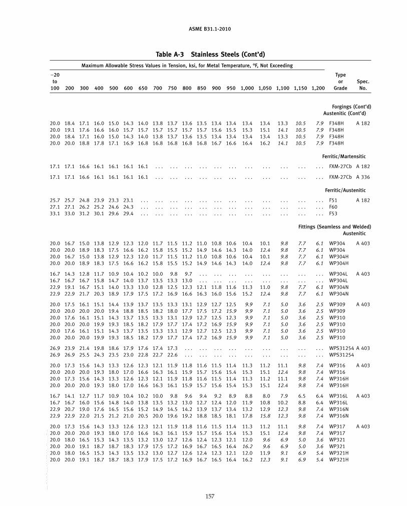
ASME B31.1-2010
Table A-3 Stainless Steels (Cont’d)
Maximum Allowable Stress Values in Tension, ksi, for Metal Temperature, °F, Not Exceeding
−20 Typeto or Spec.
100 200 300 400 500 600 650 700 750 800 850 900 950 1,000 1,050 1,100 1,150 1,200 Grade No.
Forgings (Cont’d)Austenitic (Cont’d)
20.0 18.4 17.1 16.0 15.0 14.3 14.0 13.8 13.7 13.6 13.5 13.4 13.4 13.4 13.4 13.3 10.5 7.9 F348H A 18220.0 19.1 17.6 16.6 16.0 15.7 15.7 15.7 15.7 15.7 15.7 15.6 15.5 15.3 15.1 14.1 10.5 7.9 F348H20.0 18.4 17.1 16.0 15.0 14.3 14.0 13.8 13.7 13.6 13.5 13.4 13.4 13.4 13.4 13.3 10.5 7.9 F348H20.0 20.0 18.8 17.8 17.1 16.9 16.8 16.8 16.8 16.8 16.8 16.7 16.6 16.4 16.2 14.1 10.5 7.9 F348H
Ferritic/Martensitic
17.1 17.1 16.6 16.1 16.1 16.1 16.1 . . . . . . . . . . . . . . . . . . . . . . . . . . . . . . . . . FXM-27Cb A 182
17.1 17.1 16.6 16.1 16.1 16.1 16.1 . . . . . . . . . . . . . . . . . . . . . . . . . . . . . . . . . FXM-27Cb A 336
Ferritic/Austenitic
25.7 25.7 24.8 23.9 23.3 23.1 . . . . . . . . . . . . . . . . . . . . . . . . . . . . . . . . . . . . F51 A 18227.1 27.1 26.2 25.2 24.6 24.3 . . . . . . . . . . . . . . . . . . . . . . . . . . . . . . . . . . . . F6033.1 33.0 31.2 30.1 29.6 29.4 . . . . . . . . . . . . . . . . . . . . . . . . . . . . . . . . . . . . F53
Fittings (Seamless and Welded)Austenitic
20.0 16.7 15.0 13.8 12.9 12.3 12.0 11.7 11.5 11.2 11.0 10.8 10.6 10.4 10.1 9.8 7.7 6.1 WP304 A 40320.0 20.0 18.9 18.3 17.5 16.6 16.2 15.8 15.5 15.2 14.9 14.6 14.3 14.0 12.4 9.8 7.7 6.1 WP30420.0 16.7 15.0 13.8 12.9 12.3 12.0 11.7 11.5 11.2 11.0 10.8 10.6 10.4 10.1 9.8 7.7 6.1 WP304H20.0 20.0 18.9 18.3 17.5 16.6 16.2 15.8 15.5 15.2 14.9 14.6 14.3 14.0 12.4 9.8 7.7 6.1 WP304H
16.7 14.3 12.8 11.7 10.9 10.4 10.2 10.0 9.8 9.7 . . . . . . . . . . . . . . . . . . . . . . . . WP304L A 40316.7 16.7 16.7 15.8 14.7 14.0 13.7 13.5 13.3 13.0 . . . . . . . . . . . . . . . . . . . . . . . . WP304L22.9 19.1 16.7 15.1 14.0 13.3 13.0 12.8 12.5 12.3 12.1 11.8 11.6 11.3 11.0 9.8 7.7 6.1 WP304N22.9 22.9 21.7 20.3 18.9 17.9 17.5 17.2 16.9 16.6 16.3 16.0 15.6 15.2 12.4 9.8 7.7 6.1 WP304N
20.0 17.5 16.1 15.1 14.4 13.9 13.7 13.5 13.3 13.1 12.9 12.7 12.5 9.9 7.1 5.0 3.6 2.5 WP309 A 40320.0 20.0 20.0 20.0 19.4 18.8 18.5 18.2 18.0 17.7 17.5 17.2 15.9 9.9 7.1 5.0 3.6 2.5 WP30920.0 17.6 16.1 15.1 14.3 13.7 13.5 13.3 13.1 12.9 12.7 12.5 12.3 9.9 7.1 5.0 3.6 2.5 WP31020.0 20.0 20.0 19.9 19.3 18.5 18.2 17.9 17.7 17.4 17.2 16.9 15.9 9.9 7.1 5.0 3.6 2.5 WP31020.0 17.6 16.1 15.1 14.3 13.7 13.5 13.3 13.1 12.9 12.7 12.5 12.3 9.9 7.1 5.0 3.6 2.5 WP31020.0 20.0 20.0 19.9 19.3 18.5 18.2 17.9 17.7 17.4 17.2 16.9 15.9 9.9 7.1 5.0 3.6 2.5 WP310
26.9 23.9 21.4 19.8 18.6 17.9 17.6 17.4 17.3 . . . . . . . . . . . . . . . . . . . . . . . . . . . WPS31254 A 40326.9 26.9 25.5 24.3 23.5 23.0 22.8 22.7 22.6 . . . . . . . . . . . . . . . . . . . . . . . . . . . WPS31254
20.0 17.3 15.6 14.3 13.3 12.6 12.3 12.1 11.9 11.8 11.6 11.5 11.4 11.3 11.2 11.1 9.8 7.4 WP316 A 40320.0 20.0 20.0 19.3 18.0 17.0 16.6 16.3 16.1 15.9 15.7 15.6 15.4 15.3 15.1 12.4 9.8 7.4 WP31620.0 17.3 15.6 14.3 13.3 12.6 12.3 12.1 11.9 11.8 11.6 11.5 11.4 11.3 11.2 11.1 9.8 7.4 WP316H20.0 20.0 20.0 19.3 18.0 17.0 16.6 16.3 16.1 15.9 15.7 15.6 15.4 15.3 15.1 12.4 9.8 7.4 WP316H
16.7 14.1 12.7 11.7 10.9 10.4 10.2 10.0 9.8 9.6 9.4 9.2 8.9 8.8 8.0 7.9 6.5 6.4 WP316L A 40316.7 16.7 16.0 15.6 14.8 14.0 13.8 13.5 13.2 13.0 12.7 12.4 12.0 11.9 10.8 10.2 8.8 6.4 WP316L22.9 20.7 19.0 17.6 16.5 15.6 15.2 14.9 14.5 14.2 13.9 13.7 13.4 13.2 12.9 12.3 9.8 7.4 WP316N22.9 22.9 22.0 21.5 21.2 21.0 20.5 20.0 19.6 19.2 18.8 18.5 18.1 17.8 15.8 12.3 9.8 7.4 WP316N
20.0 17.3 15.6 14.3 13.3 12.6 12.3 12.1 11.9 11.8 11.6 11.5 11.4 11.3 11.2 11.1 9.8 7.4 WP317 A 40320.0 20.0 20.0 19.3 18.0 17.0 16.6 16.3 16.1 15.9 15.7 15.6 15.4 15.3 15.1 12.4 9.8 7.4 WP31720.0 18.0 16.5 15.3 14.3 13.5 13.2 13.0 12.7 12.6 12.4 12.3 12.1 12.0 9.6 6.9 5.0 3.6 WP32120.0 20.0 19.1 18.7 18.7 18.3 17.9 17.5 17.2 16.9 16.7 16.5 16.4 16.2 9.6 6.9 5.0 3.6 WP32120.0 18.0 16.5 15.3 14.3 13.5 13.2 13.0 12.7 12.6 12.4 12.3 12.1 12.0 11.9 9.1 6.9 5.4 WP321H20.0 20.0 19.1 18.7 18.7 18.3 17.9 17.5 17.2 16.9 16.7 16.5 16.4 16.2 12.3 9.1 6.9 5.4 WP321H
157
Copyright ASME International Provided by IHS under license with ASME No reproduction or networking permitted without license from IHS
--`,,```````,,```,`,`,,,,`,`,`,`-`-`,,`,,`,`,,`---

ASME B31.1-2010
Table A-3 Stainless Steels (Cont’d)
Specified SpecifiedUNS Minimum Minimum E
Spec. Type or Alloy Nominal P- Tensile, Yield, orNo. Grade Class No. Composition No. Notes ksi ksi F
Fittings (Seamless and Welded) (Cont’d)Austenitic (Cont’d)
A 403 WP347 . . . S34700 18Cr–10Ni–Cb 8 (4)(7)(10)(11) 75 30 1.00WP347 . . . S34700 18Cr–10Ni–Cb 8 (4)(7)(9)(10)(11) 75 30 1.00WP347H . . . S34709 18Cr–10Ni–Cb 8 (4)(7)(11) 75 30 1.00WP347H . . . S34709 18Cr–10Ni–Cb 8 (4)(7)(9)(11) 75 30 1.00
A 403 WP348 . . . S34800 18Cr–10Ni–Cb 8 (4)(7)(10)(11) 75 30 1.00WP348 . . . S34800 18Cr–10Ni–Cb 8 (4)(7)(9)(10)(11) 75 30 1.00WP348H . . . S34809 18Cr–10Ni–Cb 8 (4)(7)(11) 75 30 1.00WP348H . . . S34809 18Cr–10Ni–Cb 8 (4)(7)(9)(11) 75 30 1.00
Ferritic/Austenitic
A 815 S31803 . . . S31803 22Cr–5.5Ni–3Mo–N 10H (1)(33)(34) 90 65 1.00S32205 . . . S32205 22Cr–5.5Ni–3Mo–N 10H (1)(33)(34) 95 70 1.00
CastingsAustenitic
A 351 CF3 . . . J92500 18Cr–8Ni 8 (1)(5)(26) 70 30 0.80CF3 . . . J92500 18Cr–8Ni 8 (1)(5)(9)(26) 70 30 0.80CF3A . . . J92500 18Cr–8Ni 8 (1)(5)(26) 77.5 35 0.80CF3A . . . J92500 18Cr–8Ni 8 (1)(5)(9)(26) 77.5 35 0.80CF3M . . . J92800 18Cr–12Ni–2Mo 8 (1)(5)(13)(26) 70 30 0.80CF3M . . . J92800 18Cr–12Ni–2Mo 8 (1)(5)(9)(13)(26) 70 30 0.80
A 351 CF8 . . . J92600 18Cr–8Ni 8 (5)(10)(26) 70 30 0.80CF8 . . . J92600 18Cr–8Ni 8 (5)(9)(10)(26) 70 30 0.80CF8C . . . J92710 18Cr–10Ni–Cb 8 (1)(5)(10)(26) 70 30 0.80CF8C . . . J92710 18Cr–10Ni–Cb 8 (1)(5)(9)(10)(26) 70 30 0.80CF8M . . . J92900 16Cr–12Ni–2Mo 8 (5)(13)(26) 70 30 0.80CF8M . . . J92900 16Cr–12Ni–2Mo 8 (5)(9)(13)(26) 70 30 0.80
A 351 CH8 . . . J93400 25Cr–12Ni 8 (1)(5)(10)(26) 65 28 0.80CH8 . . . J93400 25Cr–12Ni 8 (1)(5)(9)(10)(26) 65 28 0.80CH20 . . . J93402 25Cr–12Ni 8 (1)(5)(10)(26) 70 30 0.80CH20 . . . J93402 25Cr–12Ni 8 (1)(5)(9)(10)(26) 70 30 0.80CK20 . . . J94202 25Cr–20Ni 8 (1)(5)(10)(26) 65 28 0.80CK20 . . . J94202 25Cr–20Ni 8 (1)(5)(9)(10)(26) 65 28 0.80
Ferritic/Martensitic
A 217 CA15 . . . J91150 13Cr–1⁄2 Mo 6 (1)(3)(5) 90 65 0.80
(10)
158
Copyright ASME International Provided by IHS under license with ASME No reproduction or networking permitted without license from IHS
--`,,```````,,```,`,`,,,,`,`,`,`-`-`,,`,,`,`,,`---
标准分享网 www.bzfxw.com 免费下载

ASME B31.1-2010
Table A-3 Stainless Steels (Cont’d)
Maximum Allowable Stress Values in Tension, ksi, for Metal Temperature, °F, Not Exceeding
−20 Typeto or Spec.
100 200 300 400 500 600 650 700 750 800 850 900 950 1,000 1,050 1,100 1,150 1,200 Grade No.
Fittings (Seamless and Welded) (Cont’d)Austenitic (Cont’d)
20.0 18.4 17.1 16.0 15.0 14.3 14.0 13.8 13.7 13.6 13.5 13.4 13.4 13.4 12.1 9.1 6.1 4.4 WP347 A 40320.0 20.0 18.8 17.8 17.2 16.9 16.8 16.8 16.8 16.8 16.8 16.7 16.6 16.0 12.1 9.1 6.1 4.4 WP34720.0 18.4 17.1 16.0 15.0 14.3 14.0 13.8 13.7 13.6 13.5 13.4 13.4 13.4 13.4 13.3 10.5 7.9 WP347H20.0 20.0 18.8 17.8 17.1 16.9 16.8 16.8 16.8 16.8 16.8 16.7 16.6 16.4 16.2 14.1 10.5 7.9 WP347H
20.0 18.4 17.1 16.0 15.0 14.3 14.0 13.8 13.7 13.6 13.5 13.4 13.4 13.4 12.1 9.1 6.1 4.4 WP348 A 40320.0 20.0 18.8 17.8 17.2 16.9 16.8 16.8 16.8 16.8 16.8 16.7 16.6 16.0 12.1 9.1 6.1 4.4 WP34820.0 18.4 17.1 16.0 15.0 14.3 14.0 13.8 13.7 13.6 13.5 13.4 13.4 13.4 13.4 13.3 10.5 7.9 WP348H20.0 20.0 18.8 17.8 17.1 16.9 16.8 16.8 16.8 16.8 16.8 16.7 16.6 16.4 16.2 14.1 10.5 7.9 WP348H
Ferritic/Austenitic
25.7 25.7 24.8 23.9 23.3 23.1 . . . . . . . . . . . . . . . . . . . . . . . . . . . . . . . . . . . . S31803 A 81527.1 27.1 26.2 25.2 24.6 24.3 . . . . . . . . . . . . . . . . . . . . . . . . . . . . . . . . . . . . S32205
CastingsAustenitic
16.0 13.3 12.0 11.0 10.4 9.8 9.6 9.4 9.2 9.0 . . . . . . . . . . . . . . . . . . . . . . . . CF3 A 35116.0 15.2 14.1 13.7 13.5 13.3 13.0 12.7 12.4 12.1 . . . . . . . . . . . . . . . . . . . . . . . . CF317.7 15.6 14.0 12.9 12.1 11.5 11.2 10.9 . . . . . . . . . . . . . . . . . . . . . . . . . . . . . . CF3A17.7 16.8 15.6 15.1 15.0 15.0 15.0 14.8 . . . . . . . . . . . . . . . . . . . . . . . . . . . . . . CF3A16.0 13.8 12.4 11.4 10.6 10.1 9.8 9.7 9.5 9.4 9.3 . . . . . . . . . . . . . . . . . . . . . CF3M16.0 16.0 15.5 15.4 14.3 13.6 13.3 13.0 12.8 12.7 12.5 . . . . . . . . . . . . . . . . . . . . . CF3M
16.0 13.3 12.0 11.0 10.4 9.8 9.6 9.4 9.2 9.0 8.8 8.6 8.5 8.3 7.6 6.0 4.8 3.8 CF8 A 35116.0 15.2 14.1 13.7 13.5 13.3 13.0 12.7 12.4 12.1 11.9 11.7 11.4 9.8 7.6 6.0 4.8 3.8 CF816.0 13.3 12.0 11.0 10.4 9.8 9.6 9.4 9.2 9.0 8.8 8.6 8.5 8.3 8.1 7.3 4.9 3.6 CF8C16.0 15.2 14.1 13.7 13.5 13.3 13.0 12.7 12.4 12.1 11.9 11.7 11.4 11.2 9.7 7.3 4.9 3.6 CF8C16.0 13.8 12.4 11.4 10.6 10.1 9.8 9.7 9.5 9.4 9.3 9.2 9.1 9.1 9.0 7.1 5.5 4.3 CF8M16.0 16.0 15.5 15.4 14.3 13.6 13.3 13.0 12.8 12.7 12.5 12.4 12.3 11.9 9.2 7.1 5.5 4.3 CF8M
14.9 12.2 11.3 10.8 10.5 10.1 9.9 9.7 9.4 9.1 8.8 8.5 8.2 7.9 6.8 5.2 4.0 3.0 CH8 A 35114.9 13.6 12.7 12.3 12.3 12.3 12.3 12.2 12.0 11.8 11.5 11.1 10.6 8.9 6.8 5.2 4.0 3.0 CH816.0 13.1 12.1 11.6 11.2 10.8 10.6 10.4 10.1 9.8 9.5 9.1 8.8 8.5 6.8 5.2 4.0 3.0 CH2016.0 14.6 13.6 13.3 13.2 13.2 13.2 13.1 13.0 12.7 12.4 11.9 11.4 8.9 6.8 5.2 4.0 3.0 CH2014.9 12.2 11.3 10.8 10.5 10.1 9.9 9.7 9.4 9.1 8.8 8.5 8.2 7.9 7.6 6.8 5.8 4.8 CK2014.9 13.6 12.7 12.3 12.3 12.3 12.3 12.2 12.0 11.8 11.5 11.1 10.6 9.0 7.8 6.8 5.8 4.8 CK20
Ferritic/Martensitic
20.6 20.6 20.6 20.6 20.6 20.6 20.6 20.6 20.6 20.6 20.1 12.0 7.4 4.7 3.0 1.9 1.2 0.8 CA15 A 217
(10)
159
Copyright ASME International Provided by IHS under license with ASME No reproduction or networking permitted without license from IHS
--`,,```````,,```,`,`,,,,`,`,`,`-`-`,,`,,`,`,,`---

ASME B31.1-2010
Table A-3 Stainless Steels (Cont’d)
Specified SpecifiedUNS Minimum Minimum E
Spec. Type or Alloy Nominal P- Tensile, Yield, orNo. Grade Class No. Composition No. Notes ksi ksi F
BarAustenitic
A 479 304 . . . S30400 18Cr–8Ni 8 (10) 75 30 1.00304 . . . S30400 18Cr–8Ni 8 (9)(10) 75 30 1.00304H . . . S30409 18Cr–8Ni 8 . . . 75 30 1.00304H . . . S30409 18Cr–8Ni 8 (9) 75 30 1.00
A 479 304L . . . S30403 18Cr–8Ni 8 (25) 70 25 1.00304L . . . S30403 18Cr–8Ni 8 (9)(25) 70 25 1.00304N . . . S30451 18Cr–8Ni–N 8 (10) 80 35 1.00304N . . . S30451 18Cr–8Ni–N 8 (9)(10) 80 35 1.00
A 479 . . . . . . S30815 21Cr–11Ni–N 8 (1) 87 45 1.00. . . . . . S30815 21Cr–11Ni–N 8 (1)(9) 87 45 1.00
A 479 310S . . . S31008 25Cr–20Ni 8 (10)(11)(15) 75 30 1.00310S . . . S31008 25Cr–20Ni 8 (10)(11)(14) 75 30 1.00310S . . . S31008 25Cr–20Ni 8 (9)(10)(11) 75 30 1.00. . . . . . S31254 20Cr–18Ni–6Mo 8 (1) 95 44 1.00. . . . . . S31254 20Cr–18Ni–6Mo 8 (1)(9) 95 44 1.00
A 479 316 . . . S31600 16Cr–12Ni–2Mo 8 (10) 75 30 1.00316 . . . S31600 16Cr–12Ni–2Mo 8 (9)(10) 75 30 1.00316H . . . S31609 16Cr–12Ni–2Mo 8 . . . 75 30 1.00316H . . . S31609 16Cr–12Ni–2Mo 8 (9) 75 30 1.00
A 479 316L . . . S31603 16Cr–12Ni–2Mo 8 (1)(25)(38) 70 25 1.00316L . . . S31603 16Cr–12Ni–2Mo 8 (1)(9)(25)(38) 70 25 1.00316N . . . S31651 16Cr–12Ni–2Mo 8 (10) 80 35 1.00316N . . . S31651 16Cr–12Ni–2Mo 8 (9)(10) 80 35 1.00
A 479 321 . . . S32100 18Cr–10Ni–Ti 8 (10) 75 30 1.00321 . . . S32100 18Cr–10Ni–Ti 8 (9)(10) 75 30 1.00321H . . . S32109 18Cr–10Ni–Ti 8 . . . 75 30 1.00321H . . . S32109 18Cr–10Ni–Ti 8 (9) 75 30 1.00. . . . . . S32550 25.5Cr–5.5Ni–3.5Mo–2Cu 10H (1)(35)(36) 110 80 1.00
A 479 347 . . . S34700 18Cr–10Ni–Cb 8 (10) 75 30 1.00347 . . . S34700 18Cr–10Ni–Cb 8 (9)(10) 75 30 1.00347H . . . S34709 18Cr–10Ni–Cb 8 . . . 75 30 1.00347H . . . S34709 18Cr–10Ni–Cb 8 (9) 75 30 1.00
A 479 348 . . . S34800 18Cr–10Ni–Cb 8 (10) 75 30 1.00348 . . . S34800 18Cr–10Ni–Cb 8 (9)(10) 75 30 1.00348H . . . S34809 18Cr–10Ni–Cb 8 . . . 75 30 1.00348H . . . S34809 18Cr–10Ni–Cb 8 (9) 75 30 1.00
Ferritic/Martensitic
A 479 XM-27 . . . S44627 27Cr–1Mo 10I (2) 65 40 1.00
Ferritic/Austenitic
A 479 S31803 . . . S31803 22Cr–5.5Ni–3Mo–N 10H (1)(33)(34) 90 65 1.00
160
Copyright ASME International Provided by IHS under license with ASME No reproduction or networking permitted without license from IHS
--`,,```````,,```,`,`,,,,`,`,`,`-`-`,,`,,`,`,,`---
标准分享网 www.bzfxw.com 免费下载

ASME B31.1-2010
Table A-3 Stainless Steels (Cont’d)
Maximum Allowable Stress Values in Tension, ksi, for Metal Temperature, °F, Not Exceeding
−20 Typeto or Spec.
100 200 300 400 500 600 650 700 750 800 850 900 950 1,000 1,050 1,100 1,150 1,200 Grade No.
BarAustenitic
20.0 16.7 15.0 13.8 12.9 12.3 12.0 11.7 11.5 11.2 11.0 10.8 10.6 10.4 10.1 9.8 7.7 6.1 304 A 47920.0 20.0 18.9 18.3 17.5 16.6 16.2 15.8 15.5 15.2 14.9 14.6 14.3 14.0 12.4 9.8 7.7 6.1 30420.0 16.7 15.0 13.8 12.9 12.3 12.0 11.7 11.5 11.2 11.0 10.8 10.6 10.4 10.1 9.8 7.7 6.1 304H20.0 20.0 18.9 18.3 17.5 16.6 16.2 15.8 15.5 15.2 14.9 14.6 14.3 14.0 12.4 9.8 7.7 6.1 304H
16.7 14.3 12.8 11.7 10.9 10.4 10.2 10.0 9.8 9.7 . . . . . . . . . . . . . . . . . . . . . . . . 304L A 47916.7 16.7 16.7 15.8 14.7 14.0 13.7 13.5 13.3 13.0 . . . . . . . . . . . . . . . . . . . . . . . . 304L22.9 19.1 16.7 15.1 14.0 13.3 13.0 12.8 12.5 12.3 12.1 11.8 11.6 11.3 11.0 9.8 7.7 6.1 304N22.9 22.9 21.7 20.3 18.9 17.9 17.5 17.2 16.9 16.6 16.3 16.0 15.6 15.2 12.4 9.8 7.7 6.1 304N
24.9 24.7 22.0 19.9 18.5 17.7 17.4 17.2 17.0 16.8 16.6 16.4 16.2 14.9 11.6 9.0 6.9 5.2 . . . A 47924.9 24.7 23.3 22.4 21.8 21.4 21.2 21.0 20.8 20.6 20.3 20.0 19.1 14.9 11.6 9.0 6.9 5.2 . . .
20.0 17.6 16.1 15.1 14.3 13.7 13.5 13.3 13.1 12.9 12.7 12.5 12.3 9.9 . . . . . . . . . . . . 310S A 47920.0 17.6 16.1 15.1 14.3 13.7 13.5 13.3 13.1 12.9 12.7 12.5 12.3 9.9 . . . . . . . . . . . . 310S20.0 20.0 20.0 19.9 19.3 18.5 18.2 17.9 17.7 17.4 17.2 16.9 15.9 9.9 . . . . . . . . . . . . 310S26.9 23.9 21.4 19.8 18.6 17.9 17.6 17.4 17.3 . . . . . . . . . . . . . . . . . . . . . . . . . . . . . .26.9 26.9 25.5 24.3 23.5 23.0 22.8 22.7 22.6 . . . . . . . . . . . . . . . . . . . . . . . . . . . . . .
20.0 17.3 15.6 14.3 13.3 12.6 12.3 12.1 11.9 11.8 11.6 11.5 11.4 11.3 11.2 11.1 9.8 7.4 316 A 47920.0 20.0 20.0 19.3 18.0 17.0 16.6 16.3 16.1 15.9 15.7 15.6 15.4 15.3 15.1 12.4 9.8 7.4 31620.0 17.3 15.6 14.3 13.3 12.6 12.3 12.1 11.9 11.8 11.6 11.5 11.4 11.3 11.2 11.1 9.8 7.4 316H20.0 20.0 20.0 19.3 18.0 17.0 16.6 16.3 16.1 15.9 15.7 15.6 15.4 15.3 15.1 12.4 9.8 7.4 316H
16.7 14.1 12.7 11.7 10.9 10.4 10.2 10.0 9.8 9.6 9.4 9.2 8.9 8.8 8.0 7.9 6.5 6.4 316L A 47916.7 16.7 16.0 15.6 14.8 14.0 13.8 13.5 13.2 13.0 12.7 12.4 12.0 11.9 10.8 10.2 8.8 6.4 316L22.9 20.7 19.0 17.6 16.5 15.6 15.2 14.9 14.5 14.2 13.9 13.7 13.4 13.2 12.9 12.3 9.8 7.4 316N22.9 22.9 22.0 21.5 21.2 21.0 20.5 20.0 19.6 19.2 18.8 18.5 18.1 17.8 15.8 12.3 9.8 7.4 316N
20.0 18.0 16.5 15.3 14.3 13.5 13.2 13.0 12.7 12.6 12.4 12.3 12.1 12.0 9.6 6.9 5.0 3.6 321 A 47920.0 20.0 19.1 18.7 18.7 18.3 17.9 17.5 17.2 16.9 16.7 16.5 16.4 14.9 9.6 6.9 5.0 3.6 32120.0 18.0 16.5 15.3 14.3 13.5 13.2 13.0 12.7 12.6 12.4 12.3 12.1 12.0 11.9 9.1 6.9 5.4 321H20.0 20.0 19.1 18.7 18.7 18.3 17.9 17.5 17.2 16.9 16.7 16.5 16.4 16.2 12.3 9.1 6.9 5.4 321H31.4 31.3 29.5 28.6 28.2 . . . . . . . . . . . . . . . . . . . . . . . . . . . . . . . . . . . . . . . . . .
20.0 18.4 17.1 16.0 15.0 14.3 14.0 13.8 13.7 13.6 13.5 13.4 13.4 13.4 12.1 9.1 6.1 4.4 347 A 47920.0 20.0 18.8 17.8 17.2 16.9 16.8 16.8 16.8 16.8 16.8 16.7 16.6 16.0 12.1 9.1 6.1 4.4 34720.0 18.4 17.1 16.0 15.0 14.3 14.0 13.8 13.7 13.6 13.5 13.4 13.4 13.4 13.4 13.3 10.5 7.9 347H20.0 20.0 18.8 17.8 17.1 16.9 16.8 16.8 16.8 16.8 16.8 16.7 16.6 16.4 16.2 14.1 10.5 7.9 347H
20.0 18.4 17.1 16.0 15.0 14.3 14.0 13.8 13.7 13.6 13.5 13.4 13.4 13.4 12.1 9.1 6.1 4.4 348 A 47920.0 20.0 18.8 17.8 17.2 16.9 16.8 16.8 16.8 16.8 16.8 16.7 16.6 16.0 12.1 9.1 6.1 4.4 34820.0 18.4 17.1 16.0 15.0 14.3 14.0 13.8 13.7 13.6 13.5 13.4 13.4 13.4 13.4 13.3 10.5 7.9 348H20.0 20.0 18.8 17.8 17.1 16.9 16.8 16.8 16.8 16.8 16.8 16.7 16.6 16.4 16.2 14.1 10.5 7.9 348H
Ferritic/Martensitic
18.6 18.6 18.3 18.1 18.1 18.1 18.1 . . . . . . . . . . . . . . . . . . . . . . . . . . . . . . . . . TPXM-27 A 479
Ferritic/Austenitic
25.7 25.7 24.8 23.9 23.3 23.1 . . . . . . . . . . . . . . . . . . . . . . . . . . . . . . . . . . . . S31803 A 479
161
Copyright ASME International Provided by IHS under license with ASME No reproduction or networking permitted without license from IHS
--`,,```````,,```,`,`,,,,`,`,`,`-`-`,,`,,`,`,,`---

ASME B31.1-2010
Table A-3 Stainless Steels (Cont’d)GENERAL NOTES:(a) The tabulated specifications are ANSI/ASTM or ASTM. For ASME Boiler and Pressure Vessel Code applications, see related
specifications in Section II of the ASME Code.(b) The stress values in this Table may be interpolated to determine values for intermediate temperatures.(c) The P-Numbers indicated in this Table are identical to those adopted by the ASME Boiler and Pressure Vessel Code. Qualification of
welding procedures, welders, and welding operators is required and shall comply with the ASME Boiler and Pressure Vessel Code,Section IX, except as modified by para. 127.5.
(d) Tensile strengths and allowable stresses shown in “ksi” are “thousands of pounds per square inch.”(e) The materials listed in this Table shall not be used at design temperatures above those for which allowable stress values are given
herein or in Table A-8.(f) The tabulated stress values are S � E (weld joint efficiency factor) or S � F (material quality factor), as applicable. Weld joint
efficiency factors are shown in Table 102.4.3.(g) Pressure-temperature ratings of piping components, as published in standards referenced in this Code, may be used for components
meeting the requirements of those standards. The allowable stress values given in this Table are for use in designing pipingcomponents which are not manufactured in accordance with referenced standards.
(h) The tabulated stress values that are shown in italics are at temperatures in the range where creep and stress rupture strength governthe selection of stresses.
(10) NOTES:(1) THIS MATERIAL IS NOT ACCEPTABLE FOR USE ON BOILER EXTERNAL PIPING — SEE FIGS. 100.1.2(A) AND (B).(2) Use of this material at temperatures above 650°F is not approved because of the possibility of temper embrittlement.(3) This steel may be expected to develop embrittlement at room temperature after service at temperatures above 700°F. Consequently,
its use at higher temperatures is not recommended unless due caution is observed.(4) For fittings made from A 182 forgings over 5 in. in thickness, the allowable stress values tabulated shall be reduced by the ratio of
70 divided by 75.(5) The material quality factors and allowable stress values for these materials may be increased in accordance with para. 102.4.6.(6) Tensile strengths in parentheses are expected minimum values.(7) See MSS SP-43 for requirements for lightweight stainless steel fittings. MSS SP-43 Schedule 5S fittings shall not be used for design
temperatures above 400°F. MSS SP-43 Schedule 10S fittings shall not be used for design temperatures above 750°F.(8) The material quality factor for centrifugally cast pipe (0.85) is based on all surfaces being machined after heat treatment. The surface
finish, after machining, shall be 250 �in. arithmetic average deviation or smoother.(9) Due to relatively low yield strength of these materials, these higher allowable stress values were established at temperatures where
the short time tensile properties govern to permit the use of these alloys where slightly greater deformation is acceptable. Thesestress values exceed 67% but do not exceed 90% of the yield strength at temperature. Use of these stress values may result indimensional changes due to permanent strain. These values should not be used for the flanges of gasketed joints or otherapplications where slight amounts of distortion can cause leakage or malfunction.
(10) The allowable stress values tabulated for temperatures over 1,000°F apply only if the carbon content of the material is 0.04% orhigher.
(11) The allowable stress values tabulated for temperatures over 1,000°F apply only if the material is heat treated by heating to aminimum temperature of 1,900°F and quenching in water or rapidly cooling by other means.
(12) These allowable stress values apply to forgings over 5 in. in thickness.(13) The allowable stress values tabulated for temperatures over 800°F apply only if the carbon content of the material is 0.04% or
higher.(14) These allowable stress values shall be used only when the grain size of the material is ASTM No. 6 or coarser.(15) These allowable stress values shall be used when the grain size of the material is finer than ASTM No. 6 or when the grain size has
not been determined.(16) DELETED.(17) DELETED.(18) DELETED.(19) DELETED.(20) DELETED.(21) DELETED.(22) DELETED.(23) DELETED.(24) DELETED.(25) Use of external pressure charts for material in the form of barstock is permitted for stiffening rings only.
162
Copyright ASME International Provided by IHS under license with ASME No reproduction or networking permitted without license from IHS
--`,,```````,,```,`,`,,,,`,`,`,`-`-`,,`,,`,`,,`---
标准分享网 www.bzfxw.com 免费下载
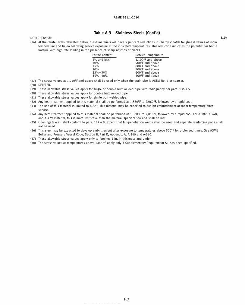
ASME B31.1-2010
Table A-3 Stainless Steels (Cont’d)NOTES (Cont’d):(26) At the ferrite levels tabulated below, these materials will have significant reductions in Charpy V-notch toughness values at room
temperature and below following service exposure at the indicated temperatures. This reduction indicates the potential for brittlefracture with high rate loading in the presence of sharp notches or cracks.
Ferrite Content Service Temperature
5% and less 1,100°F and above10% 900°F and above15% 800°F and above20% 700°F and above25%—30% 600°F and above35%—40% 500°F and above
(27) The stress values at 1,050°F and above shall be used only when the grain size is ASTM No. 6 or coarser.(28) DELETED.(29) These allowable stress values apply for single or double butt welded pipe with radiography per para. 136.4.5.(30) These allowable stress values apply for double butt welded pipe.(31) These allowable stress values apply for single butt welded pipe.(32) Any heat treatment applied to this material shall be performed at 1,880°F to 2,060°F, followed by a rapid cool.(33) The use of this material is limited to 600°F. This material may be expected to exhibit embrittlement at room temperature after
service.(34) Any heat treatment applied to this material shall be performed at 1,870°F to 2,010°F, followed by a rapid cool. For A 182, A 240,
and A 479 material, this is more restrictive than the material specification and shall be met.(35) Openings ≥ 4 in. shall conform to para. 127.4.8, except that full-penetration welds shall be used and separate reinforcing pads shall
not be used.(36) This steel may be expected to develop embrittlement after exposure to temperatures above 500°F for prolonged times. See ASME
Boiler and Pressure Vessel Code, Section II, Part D, Appendix A, A-340 and A-360.(37) These allowable stress values apply only to forgings 5 in. in thickness and under.(38) The stress values at temperatures above 1,000°F apply only if Supplementary Requirement S1 has been specified.
(10)
163
Copyright ASME International Provided by IHS under license with ASME No reproduction or networking permitted without license from IHS
--`,,```````,,```,`,`,,,,`,`,`,`-`-`,,`,,`,`,,`---

ASME B31.1-2010
Table A-4 Nickel and High Nickel Alloys
Specified SpecifiedUNS Minimum Minimum E
Spec. Alloy Temper or Nominal P- Tensile, Yield, orNo. No. Condition Composition No. Notes ksi ksi F
Seamless Pipe and Tube
B 161 N02200 Annealed Ni 41 (1)(5) 55 15 1.00N02200 Annealed Ni 41 (1)(6) 55 12 1.00N02200 Str. rel. Ni 41 (1) 65 40 1.00
B 161 N02201 Annealed Ni–Low C 41 (1)(5) 50 12 1.00N02201 Annealed Ni–Low C 41 (1)(6) 50 10 1.00N02201 Str. rel. Ni–Low C 41 (1) 60 30 1.00
B 163 N08800 Annealed Ni–Cr–Fe 45 (1)(7) 75 30 1.00N08800 Annealed Ni–Cr–Fe 45 (1)(2)(7) 75 30 1.00N08810 Annealed Ni–Cr–Fe 45 (1) 65 25 1.00N08810 Annealed Ni–Cr–Fe 45 (1)(2) 65 25 1.00
B 165 N04400 Annealed Ni–Cu 42 (1)(5) 70 28 1.00N04400 Annealed Ni–Cu 42 (1)(6) 70 25 1.00N04400 Str. rel. Ni–Cu 42 (1)(2)(3) 85 35 1.00
B 167 N06600 H.F./ann. Ni–Cr–Fe 43 (1)(5) 80 30 1.00N06600 H.F./ann. Ni–Cr–Fe 43 (1)(2)(5) 75 30 1.00N06600 H.F./ann. Ni–Cr–Fe 43 (1)(6) 75 25 1.00N06600 H.F./ann. Ni–Cr–Fe 43 (1)(2)(6) 80 25 1.00
B 167 N06600 C.D./ann. Ni–Cr–Fe 43 (1)(5) 80 35 1.00N06600 C.D./ann. Ni–Cr–Fe 43 (1)(2)(5) 80 35 1.00N06600 C.D./ann. Ni–Cr–Fe 43 (1)(6) 80 30 1.00N06600 C.D./ann. Ni–Cr–Fe 43 (1)(2)(6) 80 30 1.00
B 167 N06617 Annealed 52Ni–22Cr–13Co–9Mo 43 (1)(7) 95 35 1.00N06617 Annealed 52Ni–22Cr–13Co–9Mo 43 (1)(2)(7) 95 35 1.00
B 407 N08800 C.D./ann. Ni–Cr–Fe 45 (7) 75 30 1.00N08800 C.D./ann. Ni–Cr–Fe 45 (2)(7) 75 30 1.00N08810 Annealed Ni–Cr–Fe 45 (7) 65 25 1.00N08810 Annealed Ni–Cr–Fe 45 (2)(7) 65 25 1.00
B 423 N08825 C.W./ann. Ni–Fe–Cr–Mo–Cu 45 (1)(7) 85 35 1.00N08825 C.W./ann. Ni–Fe–Cr–Mo–Cu 45 (1)(2)(7) 85 35 1.00
B 444 N06625 Sol. ann. Ni–Cr–Mo–Cb 43 (1)(14)(18) 100 40 1.00N06625 Annealed Ni–Cr–Mo–Cb 43 (1)(2)(14) 120 60 1.00
B 622 N06022 Sol. ann. Ni–Mo–Cr–Low C 44 (1)(12) 100 45 1.00N06022 Sol. ann. Ni–Mo–Cr–Low C 44 (1)(2)(12) 100 45 1.00N10276 Sol. ann. Low C–Ni–Mo–Cr 43 (1)(12) 100 41 1.00N10276 Sol. ann. Low C–Ni–Mo–Cr 43 (1)(2)(12) 100 41 1.00R30556 Annealed Ni–Fe–Cr–Co–Mo–W 45 (1) 100 45 1.00R30556 Annealed Ni–Fe–Cr–Co–Mo–W 45 (1)(2) 100 45 1.00
B 677 N08925 Annealed Ni–Fe–Cr–Mo–Cu–Low C 45 (1) 87 43 1.00N08925 Annealed Ni–Fe–Cr–Mo–Cu–Low C 45 (1)(2) 87 43 1.00N08926 Annealed Ni–Fe–Cr–Mo–Cu–N–Low C 45 (1)(19)(20) 94 43 1.00N08926 Annealed Ni–Fe–Cr–Mo–Cu–N–Low C 45 (1)(2)(19)(20) 94 43 1.00
164
Copyright ASME International Provided by IHS under license with ASME No reproduction or networking permitted without license from IHS
--`,,```````,,```,`,`,,,,`,`,`,`-`-`,,`,,`,`,,`---
标准分享网 www.bzfxw.com 免费下载

ASME B31.1-2010
Table A-4 Nickel and High Nickel Alloys
Maximum Allowable Stress Values in Tension, ksi, for Metal Temperature, °F, Not Exceeding
−20 UNSto Alloy Spec.
100 200 300 400 500 600 650 700 750 800 850 900 950 1,000 1,050 1,100 1,150 1,200 No. No.
Seamless Pipe and Tube
10.0 10.0 10.0 10.0 10.0 10.0 . . . . . . . . . . . . . . . . . . . . . . . . . . . . . . . . . . . . N02200 B 1618.0 8.0 8.0 8.0 8.0 8.0 . . . . . . . . . . . . . . . . . . . . . . . . . . . . . . . . . . . . N02200
18.6 18.6 18.6 18.6 18.3 17.7 . . . . . . . . . . . . . . . . . . . . . . . . . . . . . . . . . . . . N02200
8.0 7.7 7.5 7.5 7.5 7.5 7.5 7.4 7.4 7.2 5.8 4.5 3.7 3.0 2.4 2.0 1.5 1.2 N02201 B 1616.7 6.4 6.3 6.2 6.2 6.2 6.2 6.2 6.1 6.0 5.8 4.5 3.7 3.0 2.4 2.0 1.5 1.2 N02201
17.1 17.1 17.0 17.0 16.8 16.3 . . . . . . . . . . . . . . . . . . . . . . . . . . . . . . . . . . . . N02201
20.0 18.5 17.8 17.2 16.8 16.3 16.1 15.9 15.7 15.5 15.3 15.1 14.9 14.7 14.5 13.0 9.8 6.6 N08800 B 16320.0 20.0 20.0 20.0 20.0 20.0 20.0 20.0 20.0 20.0 20.0 20.0 20.0 19.9 17.0 13.0 9.8 6.6 N0880016.7 15.4 14.4 13.6 12.9 12.2 11.9 11.6 11.4 11.1 10.9 10.7 10.5 10.4 10.2 10.0 9.3 7.4 N0881016.7 16.7 16.7 16.7 16.7 16.7 16.1 15.7 15.3 15.0 14.7 14.5 14.2 14.0 13.8 11.6 9.3 7.4 N08810
18.7 16.4 15.2 14.7 14.7 14.7 14.7 14.6 14.5 14.3 11.0 8.0 . . . . . . . . . . . . . . . . . . N04400 B 16516.7 14.6 13.6 13.2 13.1 13.1 13.1 13.0 12.9 12.7 11.0 8.0 . . . . . . . . . . . . . . . . . . N0440024.3 24.3 24.3 24.3 24.3 . . . . . . . . . . . . . . . . . . . . . . . . . . . . . . . . . . . . . . . N04400
20.0 19.1 18.3 17.5 16.8 16.2 15.9 15.7 15.5 15.2 15.1 14.9 10.6 7.0 4.5 3.0 2.2 2.0 N06600 B 16720.0 20.0 20.0 20.0 20.0 20.0 20.0 20.0 20.0 20.0 20.0 16.0 10.6 7.0 4.5 3.0 2.2 2.0 N0660016.7 15.9 15.2 14.6 14.0 13.5 13.3 13.1 12.9 12.7 12.5 12.4 10.6 7.0 4.5 3.0 2.2 2.0 N0660016.7 16.7 16.7 16.7 16.7 16.7 16.7 16.7 16.7 16.7 16.7 16.0 10.6 7.0 4.5 3.0 2.2 2.0 N06600
22.9 21.3 20.8 20.5 20.2 19.9 19.8 19.6 19.4 19.1 18.7 16.0 10.6 7.0 4.5 3.0 2.2 2.0 N06600 B 16722.9 22.9 22.9 22.9 22.9 22.9 22.9 22.9 22.9 22.9 22.4 16.0 10.6 7.0 4.5 3.0 2.2 2.0 N0660020.0 19.1 18.3 17.5 16.8 16.2 15.9 15.7 15.5 15.2 15.1 14.9 10.6 7.0 4.5 3.0 2.2 2.0 N0660020.0 20.0 20.0 20.0 20.0 20.0 20.0 20.0 20.0 20.0 20.0 16.0 10.6 7.0 4.5 3.0 2.2 2.0 N06600
23.3 20.8 19.2 18.1 17.2 16.6 16.4 16.2 16.0 15.9 15.8 15.7 15.6 15.5 15.4 15.4 15.3 15.3 N06617 B 16723.3 23.3 23.3 23.3 23.3 22.5 22.1 21.9 21.7 21.5 21.3 21.2 21.0 20.9 20.9 20.8 20.7 18.1 N06617
20.0 18.5 17.8 17.2 16.8 16.3 16.1 15.9 15.7 15.5 15.3 15.1 14.9 14.7 14.5 13.0 9.8 6.6 N08800 B 40720.0 20.0 20.0 20.0 20.0 20.0 20.0 20.0 20.0 20.0 20.0 20.0 20.0 19.9 17.0 13.0 9.8 6.6 N0880016.7 15.4 14.4 13.6 12.9 12.2 11.9 11.6 11.4 11.1 10.9 10.7 10.5 10.4 10.2 10.0 9.3 7.4 N0881016.7 16.7 16.7 16.7 16.7 16.5 16.1 15.7 15.3 15.0 14.7 14.5 14.2 14.0 13.8 11.6 9.3 7.4 N08810
23.3 21.4 20.3 19.4 18.5 17.8 17.5 17.3 17.2 17.0 . . . . . . . . . . . . . . . . . . . . . . . . N08825 B 42323.3 23.3 23.3 23.3 23.3 23.3 23.3 23.3 23.2 23.0 . . . . . . . . . . . . . . . . . . . . . . . . N08825
26.7 24.9 23.6 22.6 21.8 21.1 20.8 20.6 20.3 20.1 20.0 19.8 19.7 19.5 19.4 19.4 19.3 19.3 N06625 B 44434.3 34.3 34.3 33.6 32.9 32.4 32.1 31.8 31.5 31.2 30.9 30.6 30.3 29.9 29.5 29.0 21.0 13.2 N06625
28.6 26.7 24.6 22.9 21.5 20.4 20.0 19.6 19.3 19.0 . . . . . . . . . . . . . . . . . . . . . . . . N06022 B 62228.6 28.6 28.2 27.2 26.5 26.0 25.8 25.6 25.4 25.3 . . . . . . . . . . . . . . . . . . . . . . . . N0602227.3 24.9 23.0 21.3 19.9 18.8 18.2 17.8 17.4 17.1 16.9 16.7 16.6 16.5 . . . . . . . . . . . . N1027627.3 27.3 27.3 27.3 26.9 25.2 24.6 24.0 23.5 23.1 22.8 22.6 22.4 22.3 . . . . . . . . . . . . N1027628.6 25.6 23.1 21.3 20.1 19.3 18.9 18.7 18.4 18.2 18.0 17.8 17.6 17.5 17.3 17.1 16.9 13.6 R3055628.6 28.6 28.0 27.1 26.4 26.0 25.6 25.2 24.9 24.6 24.3 24.1 23.8 23.6 23.3 21.2 17.0 13.6 R30556
24.9 23.2 21.3 19.8 18.3 17.3 17.0 16.9 16.9 16.9 . . . . . . . . . . . . . . . . . . . . . . . . N08925 B 67724.9 24.9 23.9 23.0 22.1 21.4 21.1 20.8 20.4 20.1 . . . . . . . . . . . . . . . . . . . . . . . . N0892526.9 24.1 21.5 19.7 18.7 18.0 17.7 17.5 17.4 . . . . . . . . . . . . . . . . . . . . . . . . . . . N0892626.9 26.9 26.2 24.8 23.7 22.8 22.4 22.0 21.6 . . . . . . . . . . . . . . . . . . . . . . . . . . . N08926
165
Copyright ASME International Provided by IHS under license with ASME No reproduction or networking permitted without license from IHS
--`,,```````,,```,`,`,,,,`,`,`,`-`-`,,`,,`,`,,`---

ASME B31.1-2010
Table A-4 Nickel and High Nickel Alloys (Cont’d)
Specified SpecifiedUNS Minimum Minimum E
Spec. Alloy Temper or Nominal P- Tensile, Yield, orNo. No. Condition Composition No. Notes ksi ksi F
Seamless Pipe and Tube (Cont’d)
B 690 N08367 Sol. ann. Fe–Ni–Cr–Mo–Cu–N 45 (1)(8)(22) 95 45 1.00N08367 Sol. ann. Fe–Ni–Cr–Mo–Cu–N 45 (1)(2)(8)(22) 95 45 1.00N08367 Sol. ann. Fe–Ni–Cr–Mo–Cu–N 45 (1)(21) 100 45 1.00N08367 Sol. ann. Fe–Ni–Cr–Mo–Cu–N 45 (1)(2)(21) 100 45 1.00
B 729 N08020 Annealed Ni–Fe–Cr–Mo–Cu–Cb 45 (1) 80 35 1.00N08020 Annealed Ni–Fe–Cr–Mo–Cu–Cb 45 (1)(2) 80 35 1.00
Welded Pipe and Tube
B 464 N08020 Annealed Ni–Fe–Cr–Mo–Cu–Cb 45 (1) 80 35 0.85N08020 Annealed Ni–Fe–Cr–Mo–Cu–Cb 45 (1)(2) 80 35 0.85
B 468 N08020 Annealed Ni–Fe–Cr–Mo–Cu–Cb 45 (1) 80 35 0.85N08020 Annealed Ni–Fe–Cr–Mo–Cu–Cb 45 (1)(2) 80 35 0.85
B 546 N06617 Annealed 52Ni–22Cr–13Co–9Mo 43 (1)(7) 95 35 0.85N06617 Annealed 52Ni–22Cr–13Co–9Mo 43 (1)(2)(7) 95 35 0.85
B 619 N06022 Sol. ann. Ni–Mo–Cr–Low C 44 (1)(12) 100 45 0.85N06022 Sol. ann. Ni–Mo–Cr–Low C 44 (1)(2)(12) 100 45 0.85N10276 Sol. ann. Low C–Ni–Mo–Cr 43 (1)(12) 100 41 0.85N10276 Sol. ann. Low C–Ni–Mo–Cr 43 (1)(2)(12) 100 41 0.85R30556 Annealed Ni–Fe–Cr–Co–Mo–W 45 (1) 100 45 0.85R30556 Annealed Ni–Fe–Cr–Co–Mo–W 45 (1)(2) 100 45 0.85
B 626 N06022 Sol. ann. Ni–Mo–Cr–Low C 44 (1)(12) 100 45 0.85N06022 Sol. ann. Ni–Mo–Cr–Low C 44 (1)(2)(12) 100 45 0.85N10276 Sol. ann. Low C–Ni–Mo–Cr 43 (1)(12) 100 41 0.85N10276 Sol. ann. Low C–Ni–Mo–Cr 43 (1)(2)(12) 100 41 0.85R30556 Annealed Ni–Fe–Cr–Co–Mo–W 45 (1) 100 45 0.85R30556 Annealed Ni–Fe–Cr–Co–Mo–W 45 (1)(2) 100 45 0.85
B 673 N08925 Annealed Ni–Fe–Cr–Mo–Cu–Low C 45 (1) 87 43 0.85N08925 Annealed Ni–Fe–Cr–Mo–Cu–Low C 45 (1)(2) 87 43 0.85N08926 Annealed Ni–Fe–Cr–Mo–Cu–N–Low C 45 (1)(19)(20) 94 43 0.85N08926 Annealed Ni–Fe–Cr–Mo–Cu–N–Low C 45 (1)(2)(19)(20) 94 43 0.85
B 674 N08925 Annealed Ni–Fe–Cr–Mo–Cu–Low C 45 (1) 87 43 0.85N08925 Annealed Ni–Fe–Cr–Mo–Cu–Low C 45 (1)(2) 87 43 0.85N08926 Annealed Ni–Fe–Cr–Mo–Cu–N–Low C 45 (1)(19)(20) 94 43 0.85N08926 Annealed Ni–Fe–Cr–Mo–Cu–N–Low C 45 (1)(2)(19)(20) 94 43 0.85
B 675 N08367 Sol. ann. Fe–Ni–Cr–Mo–Cu–N 45 (1)(8)(22) 95 45 0.85N08367 Sol. ann. Fe–Ni–Cr–Mo–Cu–N 45 (1)(2)(8)(22) 95 45 0.85N08367 Sol. ann. Fe–Ni–Cr–Mo–Cu–N 45 (1)(8)(21) 100 45 0.85N08367 Sol. ann. Fe–Ni–Cr–Mo–Cu–N 45 (1)(2)(8)(21) 100 45 0.85
B 676 N08367 Sol. ann. Fe–Ni–Cr–Mo–Cu–N 45 (1)(8)(22) 95 45 0.85N08367 Sol. ann. Fe–Ni–Cr–Mo–Cu–N 45 (1)(2)(8)(22) 95 45 0.85N08367 Sol. ann. Fe–Ni–Cr–Mo–Cu–N 45 (1)(8)(21) 100 45 0.85N08367 Sol. ann. Fe–Ni–Cr–Mo–Cu–N 45 (1)(2)(8)(21) 100 45 0.85
166
Copyright ASME International Provided by IHS under license with ASME No reproduction or networking permitted without license from IHS
--`,,```````,,```,`,`,,,,`,`,`,`-`-`,,`,,`,`,,`---
标准分享网 www.bzfxw.com 免费下载
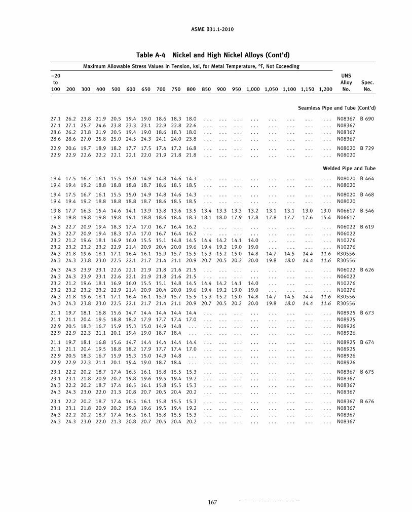
ASME B31.1-2010
Table A-4 Nickel and High Nickel Alloys (Cont’d)
Maximum Allowable Stress Values in Tension, ksi, for Metal Temperature, °F, Not Exceeding
−20 UNSto Alloy Spec.
100 200 300 400 500 600 650 700 750 800 850 900 950 1,000 1,050 1,100 1,150 1,200 No. No.
Seamless Pipe and Tube (Cont’d)
27.1 26.2 23.8 21.9 20.5 19.4 19.0 18.6 18.3 18.0 . . . . . . . . . . . . . . . . . . . . . . . . N08367 B 69027.1 27.1 25.7 24.6 23.8 23.3 23.1 22.9 22.8 22.6 . . . . . . . . . . . . . . . . . . . . . . . . N0836728.6 26.2 23.8 21.9 20.5 19.4 19.0 18.6 18.3 18.0 . . . . . . . . . . . . . . . . . . . . . . . . N0836728.6 28.6 27.0 25.8 25.0 24.5 24.3 24.1 24.0 23.8 . . . . . . . . . . . . . . . . . . . . . . . . N08367
22.9 20.6 19.7 18.9 18.2 17.7 17.5 17.4 17.2 16.8 . . . . . . . . . . . . . . . . . . . . . . . . N08020 B 72922.9 22.9 22.6 22.2 22.1 22.1 22.0 21.9 21.8 21.8 . . . . . . . . . . . . . . . . . . . . . . . . N08020
Welded Pipe and Tube
19.4 17.5 16.7 16.1 15.5 15.0 14.9 14.8 14.6 14.3 . . . . . . . . . . . . . . . . . . . . . . . . N08020 B 46419.4 19.4 19.2 18.8 18.8 18.8 18.7 18.6 18.5 18.5 . . . . . . . . . . . . . . . . . . . . . . . . N08020
19.4 17.5 16.7 16.1 15.5 15.0 14.9 14.8 14.6 14.3 . . . . . . . . . . . . . . . . . . . . . . . . N08020 B 46819.4 19.4 19.2 18.8 18.8 18.8 18.7 18.6 18.5 18.5 . . . . . . . . . . . . . . . . . . . . . . . . N08020
19.8 17.7 16.3 15.4 14.6 14.1 13.9 13.8 13.6 13.5 13.4 13.3 13.3 13.2 13.1 13.1 13.0 13.0 N06617 B 54619.8 19.8 19.8 19.8 19.8 19.1 18.8 18.6 18.4 18.3 18.1 18.0 17.9 17.8 17.8 17.7 17.6 15.4 N06617
24.3 22.7 20.9 19.4 18.3 17.4 17.0 16.7 16.4 16.2 . . . . . . . . . . . . . . . . . . . . . . . . N06022 B 61924.3 22.7 20.9 19.4 18.3 17.4 17.0 16.7 16.4 16.2 . . . . . . . . . . . . . . . . . . . . . . . . N0602223.2 21.2 19.6 18.1 16.9 16.0 15.5 15.1 14.8 14.5 14.4 14.2 14.1 14.0 . . . . . . . . . . . . N1027623.2 23.2 23.2 23.2 22.9 21.4 20.9 20.4 20.0 19.6 19.4 19.2 19.0 19.0 . . . . . . . . . . . . N1027624.3 21.8 19.6 18.1 17.1 16.4 16.1 15.9 15.7 15.5 15.3 15.2 15.0 14.8 14.7 14.5 14.4 11.6 R3055624.3 24.3 23.8 23.0 22.5 22.1 21.7 21.4 21.1 20.9 20.7 20.5 20.2 20.0 19.8 18.0 14.4 11.6 R30556
24.3 24.3 23.9 23.1 22.6 22.1 21.9 21.8 21.6 21.5 . . . . . . . . . . . . . . . . . . . . . . . . N06022 B 62624.3 24.3 23.9 23.1 22.6 22.1 21.9 21.8 21.6 21.5 . . . . . . . . . . . . . . . . . . . . . . . . N0602223.2 21.2 19.6 18.1 16.9 16.0 15.5 15.1 14.8 14.5 14.4 14.2 14.1 14.0 . . . . . . . . . . . . N1027623.2 23.2 23.2 23.2 22.9 21.4 20.9 20.4 20.0 19.6 19.4 19.2 19.0 19.0 . . . . . . . . . . . . N1027624.3 21.8 19.6 18.1 17.1 16.4 16.1 15.9 15.7 15.5 15.3 15.2 15.0 14.8 14.7 14.5 14.4 11.6 R3055624.3 24.3 23.8 23.0 22.5 22.1 21.7 21.4 21.1 20.9 20.7 20.5 20.2 20.0 19.8 18.0 14.4 11.6 R30556
21.1 19.7 18.1 16.8 15.6 14.7 14.4 14.4 14.4 14.4 . . . . . . . . . . . . . . . . . . . . . . . . N08925 B 67321.1 21.1 20.4 19.5 18.8 18.2 17.9 17.7 17.4 17.0 . . . . . . . . . . . . . . . . . . . . . . . . N0892522.9 20.5 18.3 16.7 15.9 15.3 15.0 14.9 14.8 . . . . . . . . . . . . . . . . . . . . . . . . . . . N0892622.9 22.9 22.3 21.1 20.1 19.4 19.0 18.7 18.4 . . . . . . . . . . . . . . . . . . . . . . . . . . . N08926
21.1 19.7 18.1 16.8 15.6 14.7 14.4 14.4 14.4 14.4 . . . . . . . . . . . . . . . . . . . . . . . . N08925 B 67421.1 21.1 20.4 19.5 18.8 18.2 17.9 17.7 17.4 17.0 . . . . . . . . . . . . . . . . . . . . . . . . N0892522.9 20.5 18.3 16.7 15.9 15.3 15.0 14.9 14.8 . . . . . . . . . . . . . . . . . . . . . . . . . . . N0892622.9 22.9 22.3 21.1 20.1 19.4 19.0 18.7 18.4 . . . . . . . . . . . . . . . . . . . . . . . . . . . N08926
23.1 22.2 20.2 18.7 17.4 16.5 16.1 15.8 15.5 15.3 . . . . . . . . . . . . . . . . . . . . . . . . N08367 B 67523.1 23.1 21.8 20.9 20.2 19.8 19.6 19.5 19.4 19.2 . . . . . . . . . . . . . . . . . . . . . . . . N0836724.3 22.2 20.2 18.7 17.4 16.5 16.1 15.8 15.5 15.3 . . . . . . . . . . . . . . . . . . . . . . . . N0836724.3 24.3 23.0 22.0 21.3 20.8 20.7 20.5 20.4 20.2 . . . . . . . . . . . . . . . . . . . . . . . . N08367
23.1 22.2 20.2 18.7 17.4 16.5 16.1 15.8 15.5 15.3 . . . . . . . . . . . . . . . . . . . . . . . . N08367 B 67623.1 23.1 21.8 20.9 20.2 19.8 19.6 19.5 19.4 19.2 . . . . . . . . . . . . . . . . . . . . . . . . N0836724.3 22.2 20.2 18.7 17.4 16.5 16.1 15.8 15.5 15.3 . . . . . . . . . . . . . . . . . . . . . . . . N0836724.3 24.3 23.0 22.0 21.3 20.8 20.7 20.5 20.4 20.2 . . . . . . . . . . . . . . . . . . . . . . . . N08367
167
Copyright ASME International Provided by IHS under license with ASME No reproduction or networking permitted without license from IHS
--`,,```````,,```,`,`,,,,`,`,`,`-`-`,,`,,`,`,,`---

ASME B31.1-2010
Table A-4 Nickel and High Nickel Alloys (Cont’d)
Specified SpecifiedUNS Minimum Minimum E
Spec. Alloy Temper or Nominal P- Tensile, Yield, orNo. No. Condition Composition No. Notes ksi ksi F
Welded Pipe and Tube (Cont’d)
B 704 N06625 Annealed Ni–Cr–Mo–Cb 43 (1)(14) 120 60 0.85
B 705 N06625 Annealed Ni–Cr–Mo–Cb 43 (1)(14) 120 60 0.85
B 804 N08367 Sol. ann. Fe–Ni–Cr–Mo–Cu–N 45 (1)(8) 95 45 0.85N08367 Sol. ann. Fe–Ni–Cr–Mo–Cu–N 45 (1)(2)(8) 95 45 0.85N08367 Sol. ann. Fe–Ni–Cr–Mo–Cu–N 45 (1)(8)(21) 100 45 0.85N08367 Sol. ann. Fe–Ni–Cr–Mo–Cu–N 45 (1)(2)(8)(21) 100 45 0.85
Plate, Sheet, and Strip
B 168 N06600 Annealed Ni–Cr–Fe 43 (1) 80 35 1.00N06600 Annealed Ni–Cr–Fe 43 (1)(2) 80 35 1.00N06600 Hot rolled Ni–Cr–Fe 43 (1)(4) 85 35 1.00N06600 Hot rolled Ni–Cr–Fe 43 (1)(2)(4) 85 35 1.00
B 168 N06617 Annealed 52Ni–22Cr–13Co–9Mo 43 (1)(7) 95 35 1.00N06617 Annealed 52Ni–22Cr–13Co–9Mo 43 (1)(2)(7) 95 35 1.00
B 409 N08800 Annealed Ni–Cr–Fe 45 (4)(7) 75 30 1.00N08800 Annealed Ni–Cr–Fe 45 (2)(4)(7) 75 30 1.00N08810 Annealed Ni–Cr–Fe 45 (4)(7) 65 25 1.00N08810 Annealed Ni–Cr–Fe 45 (2)(4)(7) 65 25 1.00
B 424 N08825 Annealed Ni–Fe–Cr–Mo–Cu 45 (1)(7) 85 35 1.00N08825 Annealed Ni–Fe–Cr–Mo–Cu 45 (1)(2)(7) 85 35 1.00
B 435 R30556 Annealed Ni–Fe–Cr–Co–Mo–W 45 (1) 100 45 1.00R30556 Annealed Ni–Fe–Cr–Co–Mo–W 45 (1)(2) 100 45 1.00
B 443 N06625 Sol. ann. Ni–Cr–Mo–Cb 43 (1)(14)(18) 100 40 1.00N06625 Annealed Ni–Cr–Mo–Cb 43 (1)(14) 110 55 1.00N06625 Annealed Ni–Cr–Mo–Cb 43 (1)(14)(15) 120 60 1.00
B 463 N08020 Annealed Ni–Fe–Cr–Mo–Cu–Cb 45 (1) 80 35 1.00N08020 Annealed Ni–Fe–Cr–Mo–Cu–Cb 45 (1)(12) 80 35 1.00
B 575 N06022 Sol. ann. Ni–Mo–Cr–Low C 44 (1)(12) 100 45 1.00N06022 Sol. ann. Ni–Mo–Cr–Low C 44 (1)(2)(12) 100 45 1.00N10276 Sol. ann. Low C–Ni–Mo–Cr 43 (1)(12) 100 41 1.00N10276 Sol. ann. Low C–Ni–Mo–Cr 43 (1)(2)(12) 100 41 1.00
B 625 N08925 Annealed Ni–Fe–Cr–Mo–Cu–Low C 45 (1) 87 43 1.00N08925 Annealed Ni–Fe–Cr–Mo–Cu–Low C 45 (1)(2) 87 43 1.00N08926 Annealed Ni–Fe–Cr–Mo–Cu–N–Low C 45 (1)(19)(20) 94 43 1.00N08926 Annealed Ni–Fe–Cr–Mo–Cu–N–Low C 45 (1)(2)(19)(20) 94 43 1.00
B 688 N08367 Sol. ann. Fe–Ni–Cr–Mo–Cu–N 45 (1)(7)(11)(22) 95 45 1.00N08367 Sol. ann. Fe–Ni–Cr–Mo–Cu–N 45 (1)(2)(7)(11)(22) 95 45 1.00N08367 Sol. ann. Fe–Ni–Cr–Mo–Cu–N 45 (1)(7)(10)(21) 100 45 1.00N08367 Sol. ann. Fe–Ni–Cr–Mo–Cu–N 45 (1)(2)(7)(10)(21) 100 45 1.00
168
Copyright ASME International Provided by IHS under license with ASME No reproduction or networking permitted without license from IHS
--`,,```````,,```,`,`,,,,`,`,`,`-`-`,,`,,`,`,,`---
标准分享网 www.bzfxw.com 免费下载

ASME B31.1-2010
Table A-4 Nickel and High Nickel Alloys (Cont’d)
Maximum Allowable Stress Values in Tension, ksi, for Metal Temperature, °F, Not Exceeding
−20 UNSto Alloy Spec.
100 200 300 400 500 600 650 700 750 800 850 900 950 1,000 1,050 1,100 1,150 1,200 No. No.
Welded Pipe and Tube (Cont’d)
29.1 29.1 29.1 28.5 28.0 27.5 27.3 27.0 26.8 26.5 26.3 26.0 25.7 25.4 25.1 24.7 17.9 11.2 N06625 B 704
29.1 29.1 29.1 28.5 28.0 27.5 27.3 27.0 26.8 26.5 26.3 26.0 25.7 25.4 25.1 24.7 17.9 11.2 N06625 B 705
23.1 22.2 20.2 18.7 17.4 16.5 16.1 15.8 15.5 15.3 . . . . . . . . . . . . . . . . . . . . . . . . N08367 B 80423.1 23.1 21.8 20.9 20.2 19.8 19.6 19.5 19.4 19.2 . . . . . . . . . . . . . . . . . . . . . . . . N0836724.3 22.2 20.2 18.7 17.4 16.5 16.1 15.8 15.5 15.3 . . . . . . . . . . . . . . . . . . . . . . . . N0836724.3 24.3 23.0 22.0 21.3 20.8 20.7 20.5 20.4 20.2 . . . . . . . . . . . . . . . . . . . . . . . . N08367
Plate, Sheet, and Strip
22.9 21.3 20.8 20.5 20.2 19.9 19.8 19.6 19.4 19.1 18.7 16.0 10.6 7.0 4.5 3.0 2.2 2.0 N06600 B 16822.9 22.9 22.9 22.9 22.9 22.9 22.9 22.9 22.9 22.9 22.4 16.0 10.6 7.0 4.5 3.0 2.2 2.0 N0660023.3 22.1 21.5 21.3 21.3 21.2 21.1 21.0 20.8 20.5 20.1 19.7 19.3 14.5 10.3 7.2 5.8 5.5 N0660023.3 23.3 23.3 23.3 23.3 23.3 23.3 23.3 23.3 23.3 23.3 23.3 23.3 14.5 10.3 7.2 5.8 5.5 N06600
23.3 20.8 19.2 18.1 17.2 16.6 16.4 16.2 16.0 15.9 15.8 15.7 15.6 15.5 15.4 15.4 15.3 15.3 N06617 B 16823.3 23.3 23.3 23.3 23.3 22.5 22.1 21.9 21.7 21.5 21.3 21.2 21.0 20.9 20.9 20.8 20.7 18.1 N06617
20.0 18.5 17.8 17.2 16.8 16.3 16.1 15.9 15.7 15.5 15.3 15.1 14.9 14.7 14.5 13.0 9.8 6.6 N08800 B 40920.0 20.0 20.0 20.0 20.0 20.0 20.0 20.0 20.0 20.0 20.0 20.0 20.0 19.9 17.0 13.0 9.8 6.6 N0880016.7 15.4 14.4 13.6 12.9 12.2 11.9 11.6 11.4 11.1 10.9 10.7 10.5 10.4 10.2 10.0 9.3 7.4 N0881016.7 16.7 16.7 16.7 16.7 16.5 16.1 15.7 15.3 15.0 14.7 14.5 14.2 14.0 13.8 11.6 9.3 7.4 N08810
23.3 21.4 20.3 19.4 18.5 17.8 17.5 17.3 17.2 17.0 . . . . . . . . . . . . . . . . . . . . . . . . N08825 B 42423.3 23.3 23.3 23.3 23.3 23.3 23.3 23.3 23.2 23.0 . . . . . . . . . . . . . . . . . . . . . . . . N08825
28.6 25.6 23.1 21.3 20.1 19.3 18.9 18.7 18.4 18.2 18.0 17.8 17.6 17.5 17.3 17.1 16.9 13.6 R30556 B 43528.6 28.6 28.0 27.1 26.4 26.0 25.6 25.2 24.9 24.6 24.3 24.1 23.8 23.6 23.3 21.2 17.0 13.6 R30556
26.7 24.9 23.6 22.6 21.8 21.1 20.8 20.6 20.3 20.1 20.0 19.8 19.7 19.5 19.4 19.4 19.3 19.3 N06625 B 44331.4 31.4 31.4 30.8 30.2 29.7 29.4 29.1 28.9 28.6 28.3 28.0 27.7 27.4 27.0 26.6 21.0 13.2 N0662534.3 34.3 34.3 33.6 32.9 32.4 32.1 31.8 31.5 31.2 30.9 30.6 30.3 29.9 29.5 29.0 21.0 13.2 N06625
22.9 20.6 19.7 18.9 18.2 17.7 17.5 17.4 17.2 16.8 . . . . . . . . . . . . . . . . . . . . . . . . N08020 B 46322.9 22.9 22.9 22.6 22.2 22.1 22.1 22.0 21.9 21.8 . . . . . . . . . . . . . . . . . . . . . . . . N08020
28.6 28.6 28.2 27.2 26.5 26.0 25.8 25.6 25.4 25.3 . . . . . . . . . . . . . . . . . . . . . . . . N06022 B 57528.6 28.6 28.2 27.2 26.5 26.0 25.8 25.6 25.4 25.3 . . . . . . . . . . . . . . . . . . . . . . . . N0602227.3 24.9 23.0 21.3 19.9 18.8 18.2 17.8 17.4 17.1 16.8 16.7 16.5 16.5 . . . . . . . . . . . . N1027627.3 27.3 27.3 27.3 26.9 25.2 24.6 24.0 23.5 23.1 22.8 22.6 22.4 22.3 . . . . . . . . . . . . N10276
24.9 23.2 21.3 19.8 18.3 17.3 17.0 16.9 16.9 16.9 . . . . . . . . . . . . . . . . . . . . . . . . N08925 B 62524.9 24.9 23.9 23.0 22.1 21.4 21.1 20.8 20.4 20.1 . . . . . . . . . . . . . . . . . . . . . . . . N0892526.9 24.1 21.5 19.7 18.7 18.0 17.7 17.5 17.4 . . . . . . . . . . . . . . . . . . . . . . . . . . . N0892626.9 26.9 26.2 24.8 23.7 22.8 22.4 22.0 21.6 . . . . . . . . . . . . . . . . . . . . . . . . . . . N08926
27.1 26.2 23.8 21.9 20.5 19.4 19.0 18.6 18.3 18.0 . . . . . . . . . . . . . . . . . . . . . . . . N08367 B 68827.1 27.1 25.7 24.6 23.8 23.3 23.1 22.9 22.8 22.6 . . . . . . . . . . . . . . . . . . . . . . . . N0836728.6 26.2 23.8 21.9 20.5 19.4 19.0 18.6 18.3 18.0 . . . . . . . . . . . . . . . . . . . . . . . . N0836728.6 28.6 27.0 25.8 25.0 24.5 24.3 24.1 24.0 23.8 . . . . . . . . . . . . . . . . . . . . . . . . N08367
169
Copyright ASME International Provided by IHS under license with ASME No reproduction or networking permitted without license from IHS
--`,,```````,,```,`,`,,,,`,`,`,`-`-`,,`,,`,`,,`---

ASME B31.1-2010
Table A-4 Nickel and High Nickel Alloys (Cont’d)
Specified SpecifiedUNS Minimum Minimum E
Spec. Alloy Temper or Nominal P- Tensile, Yield, orNo. No. Condition Composition No. Notes ksi ksi F
Bars, Rods, Shapes, and Forgings
B 166 N06617 Annealed 52Ni–22Cr–13Co–9Mo 43 (1)(7) 95 35 1.00N06617 Annealed 52Ni–22Cr–13Co–9Mo 43 (1)(2)(7) 95 35 1.00
B 408 N08800 Annealed Ni–Cr–Fe 45 (7) 75 30 1.00N08800 Annealed Ni–Cr–Fe 45 (2)(7) 75 30 1.00N08810 Annealed Ni–Cr–Fe 45 (7) 65 25 1.00N08810 Annealed Ni–Cr–Fe 45 (2)(7) 65 25 1.00
B 425 N08825 Annealed Ni–Fe–Cr–Mo–Cu 45 (1)(7) 85 35 1.00N08825 Annealed Ni–Fe–Cr–Mo–Cu 45 (1)(2)(7) 85 35 1.00
B 446 N06625 Sol. ann. Ni–Cr–Mo–Cb 43 (1)(14)(18) 100 40 1.00N06625 Annealed Ni–Cr–Mo–Cb 43 (1)(2)(14)(16) 110 50 1.00N06625 Annealed Ni–Cr–Mo–Cb 43 (1)(2)(14)(15)(17) 120 60 1.00
B 462 N08020 Annealed Ni–Fe–Cr–Mo–Cu–Cb 45 (1) 80 35 1.00N08020 Annealed Ni–Fe–Cr–Mo–Cu–Cb 45 (1)(2) 80 35 1.00
B 473 N08020 Annealed Cr–Ni–Fe–Mo–Cu–Cb 45 (1) 80 35 1.00N08020 Annealed Cr–Ni–Fe–Mo–Cu–Cb 45 (1)(2) 80 35 1.00
B 564 N06617 Annealed 52Ni–22Cr–13Co–9Mo 43 (1)(7) 95 35 1.00N06617 Annealed 52Ni–22Cr–13Co–9Mo 43 (1)(2)(7) 95 35 1.00N06625 Annealed Ni–Cr–Mo–Cb 43 (1)(2)(14)(16) 110 50 1.00N06625 Annealed Ni–Cr–Mo–Cb 43 (1)(2)(14)(15)(17) 120 60 1.00
B 564 N08367 Sol. ann. Fe–Ni–Cr–Mo–Cu–N 45 (1)(8)(22) 95 45 1.00N08367 Sol. ann. Fe–Ni–Cr–Mo–Cu–N 45 (1)(2)(8)(22) 95 45 1.00N08800 Annealed Ni–Cr–Fe 45 (1) 75 30 1.00N08800 Annealed Ni–Cr–Fe 45 (1)(2) 75 30 1.00N08810 Annealed Ni–Cr–Fe 45 (1) 65 25 1.00N08810 Annealed Ni–Cr–Fe 45 (1)(2) 65 25 1.00
B 572 R30556 Annealed Ni–Fe–Cr–Co–Mo–W 45 (1) 100 45 1.00R30556 Annealed Ni–Fe–Cr–Co–Mo–W 45 (1)(2) 100 45 1.00
B 574 N06022 Sol. ann. Ni–Mo–Cr–Low C 44 (1)(12) 100 45 1.00N06022 Sol. ann. Ni–Mo–Cr–Low C 44 (1)(2)(12) 100 45 1.00N10276 Sol. ann. Low C–Ni–Mo–Cr 43 (1)(12) 100 41 1.00N10276 Sol. ann. Low C–Ni–Mo–Cr 43 (1)(2)(12) 100 41 1.00
B 649 N08925 Annealed Ni–Fe–Cr–Mo–Cu–Low C 45 (1) 87 43 1.00N08925 Annealed Ni–Fe–Cr–Mo–Cu–Low C 45 (1)(2) 87 43 1.00N08926 Annealed Ni–Fe–Cr–Mo–Cu–N–Low C . . . (1) 94 43 1.00N08926 Annealed Ni–Fe–Cr–Mo–Cu–N–Low C . . . (1)(2) 94 43 1.00
B 691 N08367 Sol. ann. Fe–Ni–Cr–Mo–Cu–N 45 (1)(8)(22) 95 45 1.00N08367 Sol. ann. Fe–Ni–Cr–Mo–Cu–N 45 (1)(2)(8)(22) 95 45 1.00
170
Copyright ASME International Provided by IHS under license with ASME No reproduction or networking permitted without license from IHS
--`,,```````,,```,`,`,,,,`,`,`,`-`-`,,`,,`,`,,`---
标准分享网 www.bzfxw.com 免费下载

ASME B31.1-2010
Table A-4 Nickel and High Nickel Alloys (Cont’d)
Maximum Allowable Stress Values in Tension, ksi, for Metal Temperature, °F, Not Exceeding
−20 UNSto Alloy Spec.
100 200 300 400 500 600 650 700 750 800 850 900 950 1,000 1,050 1,100 1,150 1,200 No. No.
Bars, Rods, Shapes, and Forgings
23.3 20.8 19.2 18.1 17.2 16.6 16.4 16.2 16.0 15.9 15.8 15.7 15.6 15.5 15.4 15.4 15.3 15.3 N06617 B 16623.3 23.3 23.3 23.3 23.3 22.5 22.1 21.9 21.7 21.5 21.3 21.2 21.0 20.9 20.9 20.8 20.7 18.1 N06617
20.0 18.5 17.8 17.2 16.8 16.3 16.1 15.9 15.7 15.5 15.3 15.1 14.9 14.7 14.5 13.0 9.8 6.6 N08800 B 40820.0 20.0 20.0 20.0 20.0 20.0 20.0 20.0 20.0 20.0 20.0 20.0 20.0 19.9 17.0 13.0 9.8 6.6 N0880016.7 15.4 14.4 13.6 12.9 12.2 11.9 11.6 11.4 11.1 10.9 10.7 10.5 10.4 10.2 10.0 9.3 7.4 N0881016.7 16.7 16.7 16.7 16.7 16.5 16.1 15.7 15.3 15.0 14.7 14.5 14.2 14.0 13.8 11.6 9.3 7.4 N08810
23.3 21.4 20.3 19.4 18.5 17.8 17.5 17.3 17.2 17.0 . . . . . . . . . . . . . . . . . . . . . . . . N08825 B 42523.3 23.3 23.3 23.3 23.3 23.3 23.3 23.3 23.2 23.0 . . . . . . . . . . . . . . . . . . . . . . . . N08825
26.7 24.9 23.6 22.6 21.8 21.1 20.8 20.6 20.3 20.1 20.0 19.8 19.7 19.5 19.4 19.4 19.3 19.3 N06625 B 44631.4 31.4 31.4 30.8 30.2 29.7 29.4 29.1 28.9 28.6 28.3 28.0 27.7 27.4 27.0 26.6 21.0 13.2 N0662534.3 34.3 34.3 33.6 32.9 32.4 32.1 31.8 31.5 31.2 30.9 30.6 30.3 29.9 29.5 29.0 21.0 13.2 N06625
22.9 20.6 19.7 18.9 18.2 17.7 17.5 17.4 17.2 16.8 . . . . . . . . . . . . . . . . . . . . . . . . N08020 B 46222.9 22.9 22.6 22.2 22.1 22.1 22.0 21.9 21.8 21.8 . . . . . . . . . . . . . . . . . . . . . . . . N08020
22.9 20.6 19.7 18.9 18.2 17.7 17.5 17.4 17.2 16.8 . . . . . . . . . . . . . . . . . . . . . . . . N08020 B 47322.9 22.9 22.6 22.2 22.1 22.1 22.0 21.9 21.8 21.8 . . . . . . . . . . . . . . . . . . . . . . . . N08020
23.3 20.8 19.2 18.1 17.2 16.6 16.4 16.2 16.0 15.9 15.8 15.7 15.6 15.5 15.4 15.4 15.3 15.3 N06617 B 56423.3 23.3 23.3 23.3 23.3 22.5 22.1 21.9 21.7 21.5 21.3 21.2 21.0 20.9 20.9 20.8 20.7 18.1 N0661731.4 31.4 31.4 30.8 30.2 29.7 29.4 29.1 28.9 28.6 28.3 28.0 27.7 27.4 27.0 26.6 21.0 13.2 N0662534.3 34.3 34.3 33.6 32.9 32.4 32.1 31.8 31.5 31.2 30.9 30.6 30.3 29.9 29.5 29.0 21.0 13.2 N06625
27.1 26.2 23.8 21.9 20.5 19.4 19.0 18.6 18.3 18.0 . . . . . . . . . . . . . . . . . . . . . . . . N08367 B 56427.1 27.1 25.7 24.6 23.8 23.3 23.1 22.9 22.8 22.6 . . . . . . . . . . . . . . . . . . . . . . . . N0836720.0 18.5 17.8 17.2 16.8 16.3 16.1 15.9 15.7 15.5 15.3 15.1 14.9 14.7 14.5 13.0 9.8 6.6 N0880020.0 20.0 20.0 20.0 20.0 20.0 20.0 20.0 20.0 20.0 20.0 20.0 20.0 19.9 17.0 13.0 9.8 6.6 N0880016.7 15.4 14.4 13.6 12.9 12.2 11.9 11.6 11.4 11.1 10.9 10.7 10.5 10.4 10.2 10.0 9.3 7.4 N0881016.7 16.7 16.7 16.7 16.7 16.5 16.1 15.7 15.3 15.0 14.7 14.5 14.2 14.0 13.8 11.6 9.3 7.4 N08810
28.6 25.6 23.1 21.3 20.1 19.3 18.9 18.7 18.4 18.2 18.0 17.8 17.6 17.5 17.3 17.1 16.9 13.6 R30556 B 57228.6 28.6 28.0 27.1 26.4 26.0 25.6 25.2 24.9 24.6 24.3 24.1 23.8 23.6 23.3 21.2 17.0 13.6 R30556
28.6 22.9 22.9 22.6 22.2 22.1 22.1 22.0 21.9 21.8 . . . . . . . . . . . . . . . . . . . . . . . . N06022 B 57428.6 28.6 28.2 27.2 26.5 26.0 25.8 25.6 25.4 25.3 . . . . . . . . . . . . . . . . . . . . . . . . N0602227.3 24.9 23.0 21.3 19.9 18.8 18.2 17.8 17.4 17.1 16.9 16.7 16.6 16.5 . . . . . . . . . . . . N1027627.3 27.3 27.3 27.3 26.9 25.2 24.6 24.0 23.5 23.1 22.8 22.6 22.4 22.3 . . . . . . . . . . . . N10276
24.9 23.2 21.3 19.8 18.3 17.3 17.0 16.9 16.9 16.9 . . . . . . . . . . . . . . . . . . . . . . . . N08925 B 64924.9 24.9 23.9 23.0 22.1 21.4 21.1 20.8 20.4 20.1 . . . . . . . . . . . . . . . . . . . . . . . . N0892526.9 24.1 21.5 19.7 18.7 18.0 17.7 17.5 17.4 . . . . . . . . . . . . . . . . . . . . . . . . . . . N0892626.9 26.9 26.2 24.8 23.7 22.8 22.4 22.0 21.6 . . . . . . . . . . . . . . . . . . . . . . . . . . . N08926
27.1 26.2 23.8 21.9 20.5 19.4 19.0 18.6 18.3 18.0 . . . . . . . . . . . . . . . . . . . . . . . . N08367 B 69127.1 27.1 25.7 24.6 23.8 23.3 23.1 22.9 22.8 22.6 . . . . . . . . . . . . . . . . . . . . . . . . N08367
171
Copyright ASME International Provided by IHS under license with ASME No reproduction or networking permitted without license from IHS
--`,,```````,,```,`,`,,,,`,`,`,`-`-`,,`,,`,`,,`---

ASME B31.1-2010
Table A-4 Nickel and High Nickel Alloys (Cont’d)
Specified SpecifiedUNS Minimum Minimum E
Spec. Alloy Temper or Nominal P- Tensile, Yield, orNo. No. Condition Composition No. Notes ksi ksi F
Seamless Fittings
(10) B 366 N06022 Sol. ann. Low C–Ni–Mo–Cr 44 (1)(12) 100 45 1.00(10) N06022 Sol. ann. Low C–Ni–Mo–Cr 44 (1)(2)(12) 100 45 1.00(10) N06625 Annealed Ni–Cr–Mo–Cb 43 (1)(14) 110 50 1.00
B 366 N08020 Annealed Cr–Ni–Fe–Mo–Cu–Cb 45 (1) 80 35 . . .N08020 Annealed Cr–Ni–Fe–Mo–Cu–Cb 45 (1)(2) 80 35 . . .
(10) N08367 Annealed Fe–Ni–Cr–Mo–N 45 (1)(8)(22) 95 45 1.00(10) N08367 Annealed Fe–Ni–Cr–Mo–N 45 (1)(2)(8)(22) 95 45 1.00
(10) B 366 N08925 Annealed Low C–Ni–Fe–Cr–Mo–Cu 45 (1) 87 43 1.00(10) N08925 Annealed Low C–Ni–Fe–Cr–Mo–Cu 45 (1)(2) 87 43 1.00(10) N08926 Annealed Low C–Ni–Fe–Cr–Mo–Cu–N 45 (1) 94 43 1.00(10) N08926 Annealed Low C–Ni–Fe–Cr–Mo–Cu–N 45 (1)(2) 94 43 1.00
B 366 N10276 Sol. ann. Low C–Ni–Mo–Cr 43 (1)(12) 100 41 1.00N10276 Sol. ann. Low C–Ni–Mo–Cr 43 (1)(2)(12) 100 41 1.00R30556 Annealed Ni–Fe–Cr–Co–Mo–W 45 (1) 100 45 1.00R30556 Annealed Ni–Fe–Cr–Co–Mo–W 45 (1)(2) 100 45 1.00
(10) B 462 N08367 Sol. ann. Fe–Ni–Cr–Mo–N 45 (1)(8)(22) 95 45 1.00(10) N08367 Sol. ann. Fe–Ni–Cr–Mo–N 45 (1)(2)(8)(22) 95 45 1.00
Welded Fittings
(10) B 366 N06022 Sol. ann. Low C–Ni–Mo–Cr 44 (1)(12) 100 45 0.85(10) N06022 Sol. ann. Low C–Ni–Mo–Cr 44 (1)(12)(13) 100 45 1.00(10) N06022 Sol. ann. Low C–Ni–Mo–Cr 44 (1)(2)(12) 100 45 0.85(10) N06022 Sol. ann. Low C–Ni–Mo–Cr 44 (1)(2)(12)(13) 100 45 1.00(10) N06625 Annealed Ni–Cr–Mo–Cb 43 (1)(14) 110 50 0.85(10) N06625 Annealed Ni–Cr–Mo–Cb 43 (1)(13)(14) 110 50 1.00
(10) B366 N08020 Annealed Cr–Ni–Fe–Mo–Cu–Cb 45 (1) 80 35 0.85(10) N08020 Annealed Cr–Ni–Fe–Mo–Cu–Cb 45 (1)(13) 80 35 1.00(10) N08020 Annealed Cr–Ni–Fe–Mo–Cu–Cb 45 (1)(2) 80 35 0.85(10) N08020 Annealed Cr–Ni–Fe–Mo–Cu–Cb 45 (1)(2)(13) 80 35 1.00
(10) B 366 N08367 Sol. ann. Fe–Ni–Cr–Mo–N 45 (1)(8)(22) 95 45 0.85(10) N08367 Sol. ann. Fe–Ni–Cr–Mo–N 45 (1)(8)(13)(22) 95 45 1.00(10) N08367 Sol. ann. Fe–Ni–Cr–Mo–N 45 (1)(2)(8)(22) 95 45 0.85(10) N08367 Sol. ann. Fe–Ni–Cr–Mo–N 45 (1)(2)(8)(13)(22) 95 45 1.00
(10) B 366 N08925 Annealed Low C–Ni–Fe–Cr–Mo–Cu 45 (1) 87 43 0.85(10) N08925 Annealed Low C–Ni–Fe–Cr–Mo–Cu 45 (1)(13) 87 43 1.00(10) N08925 Annealed Low C–Ni–Fe–Cr–Mo–Cu 45 (1)(2) 87 43 0.85(10) N08925 Annealed Low C–Ni–Fe–Cr–Mo–Cu 45 (1)(2)(13) 87 43 1.00
(10) B 366 N08926 Annealed Low C–Ni–Fe–Cr–Mo–Cu–N 45 (1)(19)(20) 94 43 0.85(10) N08926 Annealed Low C–Ni–Fe–Cr–Mo–Cu–N 45 (1)(13) 94 43 1.00(10) N08926 Annealed Low C–Ni–Fe–Cr–Mo–Cu–N 45 (1)(2)(19)(20) 94 43 0.85(10) N08926 Annealed Low C–Ni–Fe–Cr–Mo–Cu–N 45 (1)(2)(13) 94 43 1.00
B 366 N10276 Sol. ann. Low C–Ni–Mo–Cr 43 (1)(12) 100 41 0.85(10) N10276 Sol. ann. Low C–Ni–Mo–Cr 43 (1)(12)(13) 100 41 1.00
N10276 Sol. ann. Low C–Ni–Mo–Cr 43 (1)(2)(12) 100 41 0.85(10) N10276 Sol. ann. Low C–Ni–Mo–Cr 43 (1)(2)(12)(13) 100 41 1.00
B 366 R30556 Annealed Ni–Fe–Cr–Co–Mo–W 45 (1)(12) 100 45 0.85(10) R30556 Annealed Ni–Fe–Cr–Co–Mo–W 45 (1)(13) 100 45 1.00
R30556 Annealed Ni–Fe–Cr–Co–Mo–W 45 (1)(2)(12) 100 45 0.85(10) R30556 Annealed Ni–Fe–Cr–Co–Mo–W 45 (1)(2)(13) 100 45 1.00
172
Copyright ASME International Provided by IHS under license with ASME No reproduction or networking permitted without license from IHS
--`,,```````,,```,`,`,,,,`,`,`,`-`-`,,`,,`,`,,`---
标准分享网 www.bzfxw.com 免费下载

ASME B31.1-2010
Table A-4 Nickel and High Nickel Alloys (Cont’d)
Maximum Allowable Stress Values in Tension, ksi, for Metal Temperature, °F, Not Exceeding
−20 UNSto Alloy Spec.
100 200 300 400 500 600 650 700 750 800 850 900 950 1,000 1,050 1,100 1,150 1,200 No. No.
Seamless Fittings
(10)28.6 26.7 24.6 22.9 21.5 20.4 20.0 19.6 19.3 19.0 . . . . . . . . . . . . . . . . . . . . . . . . N06022 B 366(10)28.6 28.6 28.2 27.2 26.5 26.0 25.8 25.6 25.4 25.3 . . . . . . . . . . . . . . . . . . . . . N06022(10)31.4 31.4 31.4 30.8 30.2 29.7 29.4 29.1 28.9 28.6 28.3 28.0 27.7 27.4 27.0 26.6 21.0 13.2 N06625
22.9 20.6 19.7 18.9 18.2 17.7 17.5 17.4 17.2 16.8 . . . . . . . . . . . . . . . . . . . . . . . . N08020 B 36622.9 22.9 22.6 22.2 22.1 22.1 22.0 21.9 21.8 21.8 . . . . . . . . . . . . . . . . . . . . . . . . N08020
(10)27.1 26.2 23.8 21.9 20.5 19.4 19.0 18.6 18.3 18.0 . . . . . . . . . . . . . . . . . . . . . . . . N08367(10)27.1 27.1 25.7 24.6 23.8 23.3 23.1 22.9 22.8 22.6 . . . . . . . . . . . . . . . . . . . . . . . . N08367
(10)24.9 23.2 21.3 19.8 18.3 17.3 16.9 16.9 16.9 . . . . . . . . . . . . . . . . . . . . . . . . . . . N08925 B 366(10)24.9 24.9 23.0 23.0 22.1 21.4 20.8 20.4 20.1 . . . . . . . . . . . . . . . . . . . . . . . . . . . N08925(10)26.9 24.1 21.5 19.7 18.7 18.0 17.7 17.5 17.4 . . . . . . . . . . . . . . . . . . . . . . . . . . . N08926(10)26.9 26.9 26.2 24.8 23.7 22.8 22.4 22.0 21.6 . . . . . . . . . . . . . . . . . . . . . . . . . . . N08926
27.3 24.9 23.0 21.3 19.9 18.8 18.2 17.8 17.4 17.1 16.9 16.7 16.6 16.5 . . . . . . . . . . . . N10276 B 36627.3 27.3 27.3 27.3 26.9 25.2 24.6 24.0 23.5 23.1 22.8 22.6 22.4 22.3 . . . . . . . . . . . . N1027628.6 25.6 23.1 21.3 20.1 19.3 18.9 18.7 18.4 18.2 18.0 17.8 17.6 17.5 17.3 17.1 16.9 13.6 R3055628.6 28.6 28.0 27.1 26.4 26.0 25.6 25.2 24.9 24.6 24.3 24.1 23.8 23.6 23.3 21.2 17.0 13.6 R30556
(10)27.1 26.2 23.8 21.9 20.5 19.4 19.0 18.6 18.3 18.0 . . . . . . . . . . . . . . . . . . . . . . . . N08367 B 462(10)27.1 27.1 25.7 24.6 23.8 23.3 23.1 22.9 22.8 22.6 . . . . . . . . . . . . . . . . . . . . . . . . N08367
Welded Fittings
(10)24.3 22.7 20.9 19.4 18.3 17.4 17.0 16.7 16.4 16.2 . . . . . . . . . . . . . . . . . . . . . . . . N06022 B 366(10)28.6 26.7 24.6 22.9 21.5 20.4 20.0 19.6 19.3 19.0 . . . . . . . . . . . . . . . . . . . . . . . . N06022(10)24.3 24.3 23.9 23.1 22.6 22.1 21.9 21.8 21.6 21.5 . . . . . . . . . . . . . . . . . . . . . . . . N06022(10)28.6 28.6 28.2 27.2 26.5 26.0 25.8 25.6 25.4 25.3 . . . . . . . . . . . . . . . . . . . . . . . . N06022(10)26.7 26.7 26.7 26.2 26.2 25.2 25.0 24.7 24.6 24.3 24.1 23.8 23.5 23.3 23.0 22.6 17.9 11.2 N06625(10)31.4 31.4 31.4 30.8 30.2 29.4 29.1 29.1 28.6 28.6 28.3 28.0 27.7 27.4 27.0 26.4 21.0 13.2 N06625
(10)19.4 17.5 16.8 16.1 15.5 15.0 14.9 14.8 14.6 14.3 . . . . . . . . . . . . . . . . . . . . . . . . N08020 B 366(10)22.9 20.6 19.7 18.9 18.2 17.7 17.5 17.4 17.2 16.8 . . . . . . . . . . . . . . . . . . . . . . . . N08020(10)19.4 19.4 19.2 18.8 18.8 18.8 18.7 18.6 18.5 18.5 . . . . . . . . . . . . . . . . . . . . . . . . N08020(10)22.9 22.9 22.6 22.2 22.1 22.1 22.0 21.9 21.8 21.8 . . . . . . . . . . . . . . . . . . . . . . . . N08020
(10)23.1 22.2 20.2 18.7 17.4 16.5 16.1 15.8 15.5 15.3 . . . . . . . . . . . . . . . . . . . . . . . . N08367 B 366(10)27.1 26.2 23.8 21.9 20.5 19.4 19.0 18.6 18.3 18.0 . . . . . . . . . . . . . . . . . . . . . . . . N08367(10)23.1 23.1 21.8 20.9 20.2 19.8 19.6 19.5 19.4 19.2 . . . . . . . . . . . . . . . . . . . . . . . . N08367(10)27.1 27.1 25.7 24.6 23.8 23.3 23.1 22.9 22.8 22.6 . . . . . . . . . . . . . . . . . . . . . . . . N08367
(10)21.1 19.7 18.1 16.8 15.6 14.7 14.4 14.4 14.4 14.4 . . . . . . . . . . . . . . . . . . . . . . . . N08925 B366(10)24.9 23.2 21.3 19.8 18.3 17.3 17.0 16.9 16.9 16.9 . . . . . . . . . . . . . . . . . . . . . . . . N08925(10)21.1 21.1 20.4 19.5 18.8 18.2 17.9 17.7 17.4 17.0 . . . . . . . . . . . . . . . . . . . . . . . . N08925(10)24.9 24.9 23.9 23.0 22.1 21.4 21.1 20.8 20.4 20.1 . . . . . . . . . . . . . . . . . . . . . . . . N08925
(10)22.9 20.5 18.3 16.7 15.9 15.3 15.0 14.9 14.8 . . . . . . . . . . . . . . . . . . . . . . . . . . . N08926 B 366(10)26.9 24.1 21.5 19.7 18.7 18.0 17.7 17.5 17.4 . . . . . . . . . . . . . . . . . . . . . . . . . . . N08926(10)22.9 22.9 22.3 21.1 20.1 19.4 19.0 18.7 18.4 . . . . . . . . . . . . . . . . . . . . . . . . . . . N08926(10)26.9 26.9 26.2 24.8 23.7 22.8 22.4 22.0 21.6 . . . . . . . . . . . . . . . . . . . . . . . . . . . N08926
23.2 21.2 19.6 18.1 16.9 16.0 15.5 15.1 14.8 14.5 14.4 14.2 14.1 14.0 . . . . . . . . . . . . N10276 B 366(10)27.3 24.9 23.0 21.3 19.9 18.8 18.2 17.8 17.4 17.1 16.9 16.7 16.6 16.5 . . . . . . . . . . . . N10276
23.2 23.2 23.2 23.2 22.9 21.4 20.9 20.4 20.0 19.6 19.4 19.2 19.0 19.0 . . . . . . . . . . . . N10276(10)27.3 27.3 27.3 27.3 26.9 25.2 24.6 24.0 23.5 23.1 22.8 22.6 22.4 22.3 . . . . . . . . . . . . N10276
24.3 21.8 19.6 18.1 17.1 16.4 16.1 15.9 15.7 15.5 15.3 15.2 15.0 14.8 14.7 14.5 14.4 11.6 R30556 B 366(10)28.6 25.6 23.1 21.3 20.1 19.3 18.9 18.7 18.4 18.2 18.0 17.8 17.6 17.5 17.3 17.1 16.9 13.6 R30556
24.3 24.3 23.8 23.0 22.5 22.1 21.7 21.4 21.1 20.9 20.7 20.5 20.2 20.0 19.8 18.0 14.4 11.6 R30556(10)28.6 28.6 28.0 27.1 26.4 26.0 25.6 25.2 24.9 24.6 24.3 24.1 23.8 23.6 23.3 21.2 17.0 13.6 R30556
173
Copyright ASME International Provided by IHS under license with ASME No reproduction or networking permitted without license from IHS
--`,,```````,,```,`,`,,,,`,`,`,`-`-`,,`,,`,`,,`---

ASME B31.1-2010
Table A-4 Nickel and High Nickel Alloys (Cont’d)GENERAL NOTES:(a) The tabulated specifications are ANSI/ASTM or ASTM. For ASME Boiler and Pressure Vessel Code applications, see related
specifications in Section II of the ASME Code.(b) The stress values in this Table may be interpolated to determine values for intermediate temperatures.(c) The P-Numbers indicated in this Table are identical to those adopted by the ASME Boiler and Pressure Vessel Code. Qualification of
welding procedures, welders, and welding operators is required and shall comply with the ASME Boiler and Pressure Vessel Code,Section IX, except as modified by para. 127.5.
(d) Tensile strengths and allowable stresses shown in “ksi” are “thousands of pounds per square inch.”(e) The materials listed in this table shall not be used at design temperatures above those for which allowable stress values are given
herein or in Table A-8.(f) The tabulated stress values are S � E (weld joint efficiency factor) or S � F (material quality factor), as applicable. Weld joint
efficiency factors are shown in Table 102.4.3.(g) Pressure-temperature ratings of piping components, as published in standards referenced in this Code, may be used for components
meeting the requirements of those standards. The allowable stress values given in this Table are for use in designing pipingcomponents which are not manufactured in accordance with referenced standards.
(h) The y coefficient p 0.4 except where Note (7) applies [see Table 104.1.2(A)].(i) The tabulated stress values that are shown in italics are at temperatures in the range where creep and stress rupture strength govern
the selection of stresses.
NOTES:(1) THIS MATERIAL IS NOT ACCEPTABLE FOR USE ON BOILER EXTERNAL PIPING — SEE FIGS. 100.1.2(A) AND (B).(2) Due to the relatively low yield strengths of these materials, these higher allowable stress values were established at temperatures
where the short time tensile properties govern to permit the use of these alloys where slightly greater deformation is acceptable.These stress values exceed 67% but do not exceed 90% of the yield strength at temperature. Use of these values may result indimensional changes due to permanent strain. These values should not be used for flanges of gasketed joints or other applicationswhere slight amounts of distortion can cause leakage or malfunction.
(3) The maximum temperature is limited to 500°F because harder temper adversely affects design stress in the creep rupturetemperature range.
(4) These values may be used for plate material only.(5) These values apply to sizes NPS 5 and smaller.(6) These values apply to sizes larger than NPS 5.(7) See Table 104.1.2(A) for y coefficient value.(8) Heat treatment after forming or welding is neither required nor prohibited. However, if heat treatment is applied, the solution
annealing treatment shall consist of heating to a minimum temperature of 2,025°F and then quenching in water or rapidly cooling byother means.
(9) These values apply to thickness less than 3⁄16 in.(10) These values apply to thickness from 3⁄16 in. up to and including 3⁄4 in.(11) These values apply to thickness more than 3⁄4 in.(12) All filler metal, including consumable insert material, shall comply with the requirements of Section IX of the ASME Boiler and
Pressure Vessel Code.(10) (13) These values (Ep1.00) apply only to Class WX fittings (all welds radiographed or ultrasonically examined).
(14) This alloy is subject to severe loss of impact strength at room temperature after exposure in the range of 1,000°F to 1,400°F.(15) The minimum tensile strength of reduced tension specimens in accordance with QW-462.1 of Section IX shall not be less than
110,000 psi.(16) These values apply to material with a thickness of greater than 4 in. prior to machining or fabricating.(17) These values apply to material with a maximum thickness of 4 in. prior to machining or fabricating.(18) For service at 1,200°F or higher, the deposited weld metal shall be of the same nominal chemistry as the base metal.(19) Heat treatment after fabrication and forming is neither required nor prohibited. If heat treatment is performed, the material shall be
heated for a sufficient time in the range of 2,010°F to 2,100°F followed by quenching in water or rapidly cooled by another means.(20) Welding electrodes or filler metal used for welding UNS N08926 shall conform to SFA-5.11 ENiCrMo-3 or ENiCrMo-4, or SFA-5.14
ERNiCrMo-3 or ERNiCrMo-4.(21) These values apply to thicknesses 3⁄16 in. or less.(22) These values apply to thicknesses greater than 3⁄16 in.
174
Copyright ASME International Provided by IHS under license with ASME No reproduction or networking permitted without license from IHS
--`,,```````,,```,`,`,,,,`,`,`,`-`-`,,`,,`,`,,`---标准分享网 www.bzfxw.com 免费下载

ASME B31.1-2010
Table A-5 begins on the next page.
175
Copyright ASME International Provided by IHS under license with ASME No reproduction or networking permitted without license from IHS
--`,,```````,,```,`,`,,,,`,`,`,`-`-`,,`,,`,`,,`---
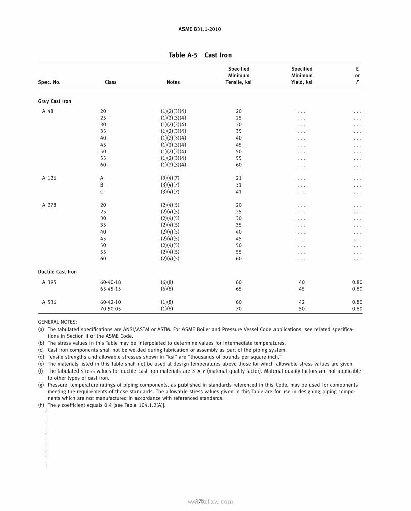
ASME B31.1-2010
Table A-5 Cast Iron
Specified Specified EMinimum Minimum or
Spec. No. Class Notes Tensile, ksi Yield, ksi F
Gray Cast Iron
A 48 20 (1)(2)(3)(4) 20 . . . . . .25 (1)(2)(3)(4) 25 . . . . . .30 (1)(2)(3)(4) 30 . . . . . .35 (1)(2)(3)(4) 35 . . . . . .40 (1)(2)(3)(4) 40 . . . . . .45 (1)(2)(3)(4) 45 . . . . . .50 (1)(2)(3)(4) 50 . . . . . .55 (1)(2)(3)(4) 55 . . . . . .60 (1)(2)(3)(4) 60 . . . . . .
A 126 A (3)(4)(7) 21 . . . . . .B (3)(4)(7) 31 . . . . . .C (3)(4)(7) 41 . . . . . .
A 278 20 (2)(4)(5) 20 . . . . . .25 (2)(4)(5) 25 . . . . . .30 (2)(4)(5) 30 . . . . . .35 (2)(4)(5) 35 . . . . . .40 (2)(4)(5) 40 . . . . . .45 (2)(4)(5) 45 . . . . . .50 (2)(4)(5) 50 . . . . . .55 (2)(4)(5) 55 . . . . . .60 (2)(4)(5) 60 . . . . . .
Ductile Cast Iron
A 395 60-40-18 (6)(8) 60 40 0.8065-45-15 (6)(8) 65 45 0.80
A 536 60-42-10 (1)(8) 60 42 0.8070-50-05 (1)(8) 70 50 0.80
GENERAL NOTES:(a) The tabulated specifications are ANSI/ASTM or ASTM. For ASME Boiler and Pressure Vessel Code applications, see related specifica-
tions in Section II of the ASME Code.(b) The stress values in this Table may be interpolated to determine values for intermediate temperatures.(c) Cast iron components shall not be welded during fabrication or assembly as part of the piping system.(d) Tensile strengths and allowable stresses shown in “ksi” are “thousands of pounds per square inch.”(e) The materials listed in this Table shall not be used at design temperatures above those for which allowable stress values are given.(f) The tabulated stress values for ductile cast iron materials are S � F (material quality factor). Material quality factors are not applicable
to other types of cast iron.(g) Pressure–temperature ratings of piping components, as published in standards referenced in this Code, may be used for components
meeting the requirements of those standards. The allowable stress values given in this Table are for use in designing piping compo-nents which are not manufactured in accordance with referenced standards.
(h) The y coefficient equals 0.4 [see Table 104.1.2(A)].
176
Copyright ASME International Provided by IHS under license with ASME No reproduction or networking permitted without license from IHS
--`,,```````,,```,`,`,,,,`,`,`,`-`-`,,`,,`,`,,`---
标准分享网 www.bzfxw.com 免费下载

ASME B31.1-2010
Table A-5 Cast Iron
Maximum Allowable Stress Values in Tension, ksi, for Metal Temperature, °F, Not Exceeding
−20 to −20 to400 450 500 600 650 650 Class Spec. No.
Gray Cast Iron
2.0 . . . . . . . . . . . . . . . 20 A 482.5 . . . . . . . . . . . . . . . 253.0 . . . . . . . . . . . . . . . 303.5 . . . . . . . . . . . . . . . 354.0 . . . . . . . . . . . . . . . 404.5 . . . . . . . . . . . . . . . 455.0 . . . . . . . . . . . . . . . 505.5 . . . . . . . . . . . . . . . 556.0 . . . . . . . . . . . . . . . 60
2.1 . . . . . . . . . . . . . . . A A 1263.1 . . . . . . . . . . . . . . . B4.1 . . . . . . . . . . . . . . . C
2.0 2.0 . . . . . . . . . . . . 20 A 2782.5 2.5 . . . . . . . . . . . . 253.0 3.0 . . . . . . . . . . . . 303.5 3.5 . . . . . . . . . . . . 35. . . . . . . . . . . . . . . 4.0 40. . . . . . . . . . . . . . . 4.5 45. . . . . . . . . . . . . . . 5.0 50. . . . . . . . . . . . . . . 5.5 55. . . . . . . . . . . . . . . 6.0 60
Ductile Cast Iron
. . . . . . . . . . . . . . . 9.6 60-40-18 A 39510.4 10.4 . . . . . . . . . . . . 65-45-15
. . . . . . . . . . . . . . . 4.8 60-42-10 A 536
. . . . . . . . . . . . . . . 5.6 70-50-05
NOTES:(1) THIS MATERIAL IS NOT ACCEPTABLE FOR BOILER EXTERNAL PIPING — SEE FIGS. 100.1.2(A) AND (B).(2) Material quality factors are not applicable to these materials.(3) For saturated steam at 250 psi (406°F), the stress values given at 400°F may be used.(4) For limitations on the use of this material, see para. 124.4.(5) This material shall not be used where the design pressure exceeds 250 psig [1 725 kPa (gage)] or where the design temperature
exceeds 450°F (230°C).(6) This material shall not be used for boiler external piping where the design pressure exceeds 350 psig [2 415 kPa (gage)] or where the
design temperature exceeds 450°F (230°C).(7) Piping components conforming to either ASME B16.1 or ASME B16.4 may be used for boiler external piping, subject to all the require-
ments of the particular standard.(8) For limitations on the use of this material, see para. 124.6.
177
Copyright ASME International Provided by IHS under license with ASME No reproduction or networking permitted without license from IHS
--`,,```````,,```,`,`,,,,`,`,`,`-`-`,,`,,`,`,,`---

ASME B31.1-2010
Table A-6 Copper and Copper Alloys
SpecifiedSize or Minimum Specified E
Spec. Temper or Thickness, P- Tensile, Minimum orNo. UNS Alloy No. Condition in. No. Notes ksi Yield, ksi F
Seamless Pipe and Tube
B 42 C10200, C12000, C12200 Annealed . . . 31 (2) 30 9 1.00C10200, C12000, C12200 Drawn 2 & under 31 (2)(4) 45 40 1.00C10200, C12000, C12200 Drawn Over 2 to 12 31 (2)(4) 36 30 1.00
B 43 C23000 Annealed . . . 31 (2) 40 12 1.00(10) C23000 Drawn . . . 31 (2)(4) 40 18 1.00
B 68 C10200, C12000, C12200 Annealed . . . 31 (1) 30 9 1.00
B 75 C10200, C12000, C12200 Annealed . . . 31 (2) 30 9 1.00C10200, C12000, C12200 Light drawn . . . 31 (2)(4) 36 30 1.00C10200, C12000, C12200 Hard drawn . . . 31 (2)(4) 45 40 1.00
B 88 C10200, C12000, C12200 Annealed . . . 31 (1) 30 9 1.00C10200, C12000, C12200 Drawn . . . 31 (1)(4) 36 30 1.00
B 111 C10200, C12000 Light drawn . . . 31 (1)(3) 36 30 1.00C10200, C12000 Hard drawn . . . 31 (1)(3) 45 40 1.00C12200, C14200 Light drawn . . . 31 (1)(3) 36 30 1.00C12200, C14200 Hard drawn . . . 31 (1)(3) 45 40 1.00
B 111 C23000 Annealed . . . 32 (1) 40 12 1.00C28000 Annealed . . . 32 (2) 50 20 1.00
(10) C44300, C44400, C44500 Annealed . . . 32 (2) 45 15 1.00C60800 Annealed . . . 35 (1) 50 19 1.00
(10) B 111 C68700 Annealed . . . 32 (1) 50 18 1.00C70400 Annealed . . . 34 (1) 38 12 1.00
(10) C70400 Light drawn . . . 34 (1)(4) 40 30 1.00
B 111 C70600 Annealed . . . 34 (2) 40 15 1.00(10) C71000 Annealed . . . 34 (2) 45 16 1.00(10) C71500 Annealed . . . 34 (2) 52 18 1.00
(10) B 280 C12200 Annealed . . . 31 (1) 30 9 1.00C12200 Drawn . . . 31 (1)(4) 36 30 1.00
(10) B 302 C12000, C12200 Drawn . . . 31 (1)(3) 36 30 1.00
B 315 C61300, C61400 Annealed . . . 35 (1) 65 28 1.00
B 466 C70600 Annealed . . . 34 (1) 38 13 1.00(10) C71500 Annealed . . . 34 (1) 52 18 1.00
Welded Pipe and Tube
(10) B 467 C70600 Annealed 41⁄2 & under 34 (1) 40 15 0.85(10) C70600 Annealed Over 41⁄2 34 (1) 38 13 0.85(10) C71500 Annealed 41⁄2 & under 34 (1) 50 20 0.85(10) C71500 Annealed Over 41⁄2 34 (1) 45 15 0.85
B 608 C61300, C61400 Annealed . . . 35 (1)(6) 70 30 0.80
178
Copyright ASME International Provided by IHS under license with ASME No reproduction or networking permitted without license from IHS
--`,,```````,,```,`,`,,,,`,`,`,`-`-`,,`,,`,`,,`---
标准分享网 www.bzfxw.com 免费下载

ASME B31.1-2010
Table A-6 Copper and Copper Alloys
Maximum Allowable Stress Values in Tension, ksi, for Metal Temperature, °F, Not Exceeding
−20to Spec.
100 150 200 250 300 350 400 450 500 550 600 650 700 750 800 UNS Alloy No. No.
Seamless Pipe and Tube
6.0 5.1 4.9 4.8 4.7 4.0 3.0 . . . . . . . . . . . . . . . . . . . . . . . . C10200, C12000, C12200 B 4212.9 12.9 12.9 12.9 12.5 11.8 4.3 . . . . . . . . . . . . . . . . . . . . . . . . C10200, C12000, C1220010.3 10.3 10.3 10.3 10.0 9.7 9.4 . . . . . . . . . . . . . . . . . . . . . . . . C10200, C12000, C12200
8.0 8.0 8.0 8.0 8.0 7.0 5.0 2.0 . . . . . . . . . . . . . . . . . . . . . C23000 B 43(10)8.0 8.0 8.0 8.0 8.0 7.0 5.0 2.0 . . . . . . . . . . . . . . . . . . . . . C23000
6.0 5.1 4.9 4.8 4.7 4.0 3.0 . . . . . . . . . . . . . . . . . . . . . . . . C10200, C12000, C12200 B 68
6.0 5.1 4.9 4.8 4.7 4.0 3.0 . . . . . . . . . . . . . . . . . . . . . . . . C10200, C12000, C12200 B 7510.3 10.3 10.3 10.3 10.0 9.7 9.4 . . . . . . . . . . . . . . . . . . . . . . . . C10200, C12000, C1220012.9 12.9 12.9 12.9 12.5 11.8 4.3 . . . . . . . . . . . . . . . . . . . . . . . . C10200, C12000, C12200
6.0 5.1 4.9 4.8 4.7 4.0 3.0 . . . . . . . . . . . . . . . . . . . . . . . . C10200, C12000, C12200 B 8810.3 10.3 10.3 10.3 10.0 9.7 9.4 . . . . . . . . . . . . . . . . . . . . . . . . C10200, C12000, C12200
10.3 10.3 10.3 10.3 10.0 9.7 9.4 . . . . . . . . . . . . . . . . . . . . . . . . C10200, C12000 B 11112.9 12.9 12.9 12.9 12.5 11.8 4.3 . . . . . . . . . . . . . . . . . . . . . . . . C10200, C1200010.3 10.3 10.3 10.3 10.0 9.7 9.4 . . . . . . . . . . . . . . . . . . . . . . . . C12200, C1420012.9 12.9 12.9 12.9 12.5 11.8 4.3 . . . . . . . . . . . . . . . . . . . . . . . . C12200, C14200
8.0 8.0 8.0 8.0 8.0 7.0 5.0 2.0 . . . . . . . . . . . . . . . . . . . . . C23000 B 11113.3 13.3 13.3 13.3 13.3 10.8 5.3 . . . . . . . . . . . . . . . . . . . . . . . . C28000
(10)10.0 10.0 10.0 10.0 10.0 9.8 3.5 2.0 . . . . . . . . . . . . . . . . . . . . . C44300, C44400, C4450012.7 12.2 12.2 12.2 12.0 10.0 6.0 4.0 2.0 . . . . . . . . . . . . . . . . . . C60800
(10)12.0 11.9 11.8 11.7 11.7 6.5 3.3 1.8 . . . . . . . . . . . . . . . . . . . . . C68700 B 1118.0 8.0 . . . . . . . . . . . . . . . . . . . . . . . . . . . . . . . . . . . . . . . C70400
(10)11.4 11.4 . . . . . . . . . . . . . . . . . . . . . . . . . . . . . . . . . . . . . . . C70400
10.0 9.7 9.5 9.3 9.0 8.8 8.7 8.5 8.0 7.0 6.0 . . . . . . . . . . . . C70600 B 111(10)10.7 10.6 10.5 10.4 10.2 10.1 9.9 9.6 9.3 8.9 8.4 7.7 7.0 . . . . . . C71000(10)12.0 11.6 11.3 11.0 10.8 10.5 10.3 10.1 9.9 9.8 9.6 9.5 9.4 . . . . . . C71500
(10)6.0 5.1 4.9 4.8 4.7 4.0 3.0 . . . . . . . . . . . . . . . . . . . . . . . . C12200 B 28010.3 10.3 10.3 10.3 10.0 9.7 9.4 . . . . . . . . . . . . . . . . . . . . . . . . C12200
(10)10.3 10.3 10.3 10.3 10.0 9.7 9.4 . . . . . . . . . . . . . . . . . . . . . . . . C12000, C12200 B 302
18.6 18.6 18.5 18.3 18.2 18.1 17.9 17.5 17.0 . . . . . . . . . . . . . . . . . . C61300, C61400 B 315
8.7 8.4 8.2 8.0 7.8 7.7 7.5 7.4 7.3 7.0 6.0 . . . . . . . . . . . . C70600 B 466(10)12.0 11.6 11.3 11.0 10.8 10.5 10.3 10.1 9.9 9.8 9.6 9.5 9.4 . . . . . . C71500
Welded Pipe and Tube
(10)8.5 8.3 8.1 7.9 7.7 7.5 7.4 7.2 6.3 5.7 4.3 . . . . . . . . . . . . C70600 B 467(10)7.4 7.2 7.0 6.8 6.7 6.5 6.4 6.3 6.2 5.7 4.3 . . . . . . . . . . . . C70600(10)11.3 10.9 10.7 10.4 10.2 10.0 9.7 9.6 9.4 9.2 9.1 . . . . . . . . . . . . C71500(10)8.5 8.2 8.0 7.8 7.6 7.5 7.3 7.2 7.0 6.9 6.8 . . . . . . . . . . . . C71500
16.0 15.9 15.8 15.7 15.6 15.5 15.4 15.1 14.6 . . . . . . . . . . . . . . . . . . C61300, C61400 B 608
179
Copyright ASME International Provided by IHS under license with ASME No reproduction or networking permitted without license from IHS
--`,,```````,,```,`,`,,,,`,`,`,`-`-`,,`,,`,`,,`---
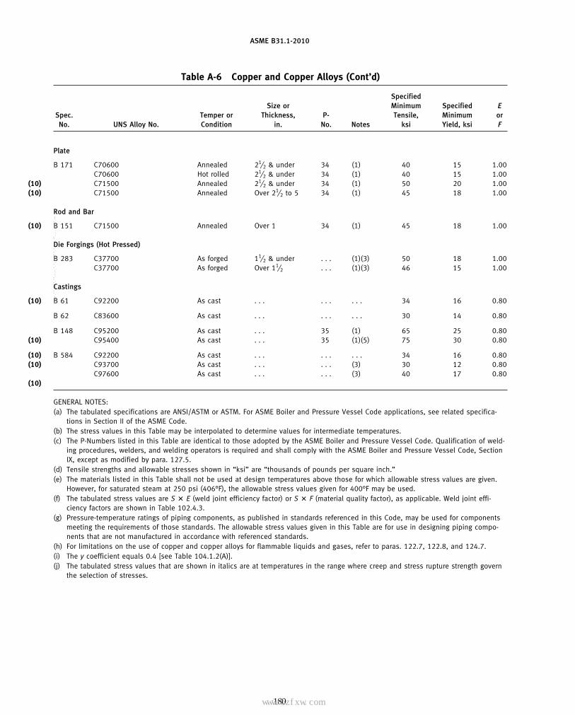
ASME B31.1-2010
Table A-6 Copper and Copper Alloys (Cont’d)
SpecifiedSize or Minimum Specified E
Spec. Temper or Thickness, P- Tensile, Minimum orNo. UNS Alloy No. Condition in. No. Notes ksi Yield, ksi F
Plate
B 171 C70600 Annealed 21⁄2 & under 34 (1) 40 15 1.00C70600 Hot rolled 21⁄2 & under 34 (1) 40 15 1.00
(10) C71500 Annealed 21⁄2 & under 34 (1) 50 20 1.00(10) C71500 Annealed Over 21⁄2 to 5 34 (1) 45 18 1.00
Rod and Bar
(10) B 151 C71500 Annealed Over 1 34 (1) 45 18 1.00
Die Forgings (Hot Pressed)
B 283 C37700 As forged 11⁄2 & under . . . (1)(3) 50 18 1.00C37700 As forged Over 11⁄2 . . . (1)(3) 46 15 1.00
Castings
(10) B 61 C92200 As cast . . . . . . . . . 34 16 0.80
B 62 C83600 As cast . . . . . . . . . 30 14 0.80
B 148 C95200 As cast . . . 35 (1) 65 25 0.80(10) C95400 As cast . . . 35 (1)(5) 75 30 0.80
(10) B 584 C92200 As cast . . . . . . . . . 34 16 0.80(10) C93700 As cast . . . . . . (3) 30 12 0.80
C97600 As cast . . . . . . (3) 40 17 0.80(10)
GENERAL NOTES:(a) The tabulated specifications are ANSI/ASTM or ASTM. For ASME Boiler and Pressure Vessel Code applications, see related specifica-
tions in Section II of the ASME Code.(b) The stress values in this Table may be interpolated to determine values for intermediate temperatures.(c) The P-Numbers listed in this Table are identical to those adopted by the ASME Boiler and Pressure Vessel Code. Qualification of weld-
ing procedures, welders, and welding operators is required and shall comply with the ASME Boiler and Pressure Vessel Code, SectionIX, except as modified by para. 127.5.
(d) Tensile strengths and allowable stresses shown in “ksi” are “thousands of pounds per square inch.”(e) The materials listed in this Table shall not be used at design temperatures above those for which allowable stress values are given.
However, for saturated steam at 250 psi (406°F), the allowable stress values given for 400°F may be used.(f) The tabulated stress values are S � E (weld joint efficiency factor) or S � F (material quality factor), as applicable. Weld joint effi-
ciency factors are shown in Table 102.4.3.(g) Pressure-temperature ratings of piping components, as published in standards referenced in this Code, may be used for components
meeting the requirements of those standards. The allowable stress values given in this Table are for use in designing piping compo-nents that are not manufactured in accordance with referenced standards.
(h) For limitations on the use of copper and copper alloys for flammable liquids and gases, refer to paras. 122.7, 122.8, and 124.7.(i) The y coefficient equals 0.4 [see Table 104.1.2(A)].(j) The tabulated stress values that are shown in italics are at temperatures in the range where creep and stress rupture strength govern
the selection of stresses.
180
Copyright ASME International Provided by IHS under license with ASME No reproduction or networking permitted without license from IHS
--`,,```````,,```,`,`,,,,`,`,`,`-`-`,,`,,`,`,,`---
标准分享网 www.bzfxw.com 免费下载

ASME B31.1-2010
Table A-6 Copper and Copper Alloys (Cont’d)
Maximum Allowable Stress Values in Tension, ksi, for Metal Temperature, °F, Not Exceeding
−20to Spec.
100 150 200 250 300 350 400 450 500 550 600 650 700 750 800 UNS Alloy No. No.
Plate
10.0 9.7 9.5 9.3 9.0 8.8 8.7 8.5 8.0 7.0 6.0 . . . . . . . . . . . . C70600 B 17110.0 9.7 9.5 9.3 9.0 8.8 8.7 8.5 8.0 7.0 6.0 . . . . . . . . . . . . C70600
(10)13.3 12.9 12.6 12.3 12.0 11.7 11.5 11.2 11.0 10.8 10.7 10.6 10.4 . . . . . . C71500(10)12.0 11.6 11.3 11.0 10.8 10.5 10.3 10.1 9.9 9.8 9.6 9.5 9.4 . . . . . . C71500
Rod and Bar
(10)12.0 11.6 11.3 11.0 10.8 10.5 10.3 10.1 9.9 9.8 9.6 9.5 9.4 . . . . . . C71500 B 151
Die Forgings (Hot Pressed)
12.0 11.3 10.8 . . . . . . . . . . . . . . . . . . . . . . . . . . . . . . . . . . . . C37700 B 28310.0 9.4 9.0 . . . . . . . . . . . . . . . . . . . . . . . . . . . . . . . . . . . . C37700
Castings
(10)7.8 7.8 7.8 7.8 7.8 7.8 6.6 6.2 5.8 4.0 . . . . . . . . . . . . . . . C92200 B 61
6.9 6.9 6.9 6.9 6.6 6.5 5.5 5.4 . . . . . . . . . . . . . . . . . . . . . C83600 B 62
13.4 12.6 12.2 11.8 11.6 11.4 11.4 11.4 11.4 9.4 5.9 . . . . . . . . . . . . C95200 B 148(10)16.0 15.2 15.0 14.8 14.8 14.8 14.8 12.8 11.1 8.8 6.8 . . . . . . . . . . . . C95400
(10)7.8 7.8 7.8 7.8 7.8 7.8 6.6 6.2 5.8 4.0 . . . . . . . . . . . . . . . C92200 B 584(10)6.4 5.9 5.5 5.3 5.3 5.2 5.1 . . . . . . . . . . . . . . . . . . . . . . . . C93700
6.0 5.8 5.6 5.5 5.4 . . . . . . . . . . . . . . . . . . . . . . . . . . . . . . C97600(10)
NOTES:(1) THIS MATERIAL IS NOT ACCEPTABLE FOR USE ON BOILER EXTERNAL PIPING — SEE FIGS. 100.1.2(A) and (B).(2) This material may be used for Boiler External Piping provided that the nominal size does not exceed 3 in. and the design temperature
does not exceed 406°F. This material shall not be used for blowoff or blowdown piping except as permitted in para. 122.1.4. Wherethreaded brass or copper pipe is used for feedwater piping, it shall have a wall thickness not less than that required for schedule 80steel pipe of the same nominal size.
(3) Welding or brazing of this material is not permitted.(4) When this material is used for welded or brazed construction, the allowable stress values used shall not exceed those given for the
same material in the annealed condition.(5) Castings that are welded or repair welded shall be heat treated at 1,150°F–1,200°F, followed by moving-air cooling. The required time
at temperature is based on the cross-section thicknesses as follows:(a) 11⁄2 hr for the first inch or fraction thereof(b) 1⁄2 hr for each additional inch or fraction thereof
(6) Welds must be made by an electric fusion welding process involving the addition of filler metal.
181
Copyright ASME International Provided by IHS under license with ASME No reproduction or networking permitted without license from IHS
--`,,```````,,```,`,`,,,,`,`,`,`-`-`,,`,,`,`,,`---

ASME B31.1-2010
Table A-7 Aluminum and Aluminum Alloys
Specified SpecifiedSize or Minimum Minimum E
Spec. Thickness, P- Tensile, Yield, orNo. UNS Alloy No. Temper in. No. Notes ksi ksi F
Drawn Seamless Tube
(10) B 210 A93003 O 0.010 to 0.500 21 (1) 14 5 1.00(10) A93003 H14 0.010 to 0.500 21 (1)(3) 20 17 1.00(10) Alclad A93003 O 0.010 to 0.500 21 (1)(4) 13 4.5 1.00(10) Alclad A93003 H14 0.010 to 0.500 21 (1)(3)(4) 19 16 1.00
B 210 A95050 O 0.018 to 0.500 21 (1) 18 6 1.00Alclad A95050 O 0.018 to 0.500 21 (1)(13)(23) 17 . . . 1.00A96061 T4 0.025 to 0.500 23 (1)(6) 30 16 1.00A96061 T6 0.025 to 0.500 23 (1)(6) 42 35 1.00
(10) A96061 T4, T6 welded 0.025 to 0.500 23 (1)(7) 24 10 1.00
Seamless Pipe and Seamless Extruded Tube
(10) B 241 A93003 O All 21 (1) 14 5 1.00(10) A93003 H18 Less than 1.000 21 (1)(3) 27 24 1.00
(10) B 241 A93003 H112 Note (20) 21 (1)(3)(20) 14 5 1.00(10) Alclad A93003 O All 21 (1)(4) 13 4.5 1.00(10) Alclad A93003 H112 All 21 (1)(3)(4) 13 4.5 1.00
B 241 A95083 O All 25 (1)(8) 39 16 1.00A95083 H112 All 25 (1)(8) 39 16 1.00A95454 O Up thru 5.000 22 (1) 31 12 1.00A95454 H112 Up thru 5.000 22 (1) 31 12 1.00
(10) B 241 A96061 T4 All 23 (1)(6)(9) 26 16 1.00(10) A96061 T6 Under 1 in. dia. 23 (1)(2)(5) 42 35 1.00
A96061 T6 All 23 (1)(6)(9) 38 35 1.00(10) A96061 T4, T6 welded All 23 (1)(7)(9) 24 10 1.00(10) A96063 T6 Note (10) 23 (1)(6)(10) 30 25 1.00
A96063 T5, T6 welded Note (10) 23 (1)(7)(10) 17 10 1.00
Drawn Seamless Condenser and Heat Exchanger Tube
B 234 A93003 H14 0.010 to 0.200 21 (1)(2) 20 17 1.00(10) Alclad A93003 H14 0.010 to 0.200 21 (1)(2)(4) 19 16 1.00
A95454 H34 0.010 to 0.200 22 (1)(2) 39 29 1.00
B 234 A96061 T4 0.025 to 0.200 23 (1)(6) 30 16 1.00A96061 T6 0.025 to 0.200 23 (1)(6) 42 35 1.00
(10) A96061 T4, T6 welded 0.025 to 0.200 23 (1)(7) 24 10 1.00
Arc-Welded Round Tube
B 547 A93003 O 0.125 to 0.500 21 (1)(15) 14 5 1.00A93003 O 0.125 to 0.500 21 (1)(16) 14 5 0.85
(10) A93003 H112 0.250 to 0.400 21 (1)(14)(15) 17 10 1.00A93003 H112 0.250 to 0.400 21 (1)(14)(16) 17 10 0.85
(10) B 547 Alclad A93003 O 0.125 to 0.499 21 (1)(4)(15) 13 4.5 1.00(10) Alclad A93003 O 0.125 to 0.499 21 (1)(4)(16) 13 4.5 0.85(10) Alclad A93003 H112 0.250 to 0.499 21 (1)(4)(14)(15) 16 9 1.00(10) Alclad A93003 H112 0.250 to 0.499 21 (1)(4)(14)(16) 16 9 0.85
182
Copyright ASME International Provided by IHS under license with ASME No reproduction or networking permitted without license from IHS
--`,,```````,,```,`,`,,,,`,`,`,`-`-`,,`,,`,`,,`---
标准分享网 www.bzfxw.com 免费下载

ASME B31.1-2010
Table A-7 Aluminum and Aluminum Alloys
Maximum Allowable Stress Values in Tension, ksi, for Metal Temperature, °F, Not Exceeding
−20to Spec.
100 150 200 250 300 350 400 UNS Alloy No. No.
Drawn Seamless Tube
(10)3.4 3.4 3.4 3.0 2.4 1.8 1.4 A93003 B 210(10)5.7 5.7 5.7 4.9 4.3 3.0 2.4 A93003(10)3.0 3.0 3.0 2.7 2.2 1.6 1.3 Alclad A93003(10)5.1 5.1 5.1 4.5 3.9 2.7 2.1 Alclad A93003
4.0 4.0 4.0 4.0 4.0 2.8 1.4 A95050 B 2103.3 3.3 3.3 3.3 3.3 2.8 1.4 Alclad A950508.6 8.6 8.6 7.4 6.9 6.3 4.5 A96061
12.0 12.0 12.0 9.9 8.4 6.3 4.5 A96061(10)6.0 6.0 6.0 5.9 5.5 4.6 3.5 A96061
Seamless Pipe and Seamless Extruded Tube
(10)3.4 3.4 3.4 3.0 2.4 1.8 1.4 A93003 B 241(10)7.8 7.8 7.7 6.3 5.4 3.5 2.5 A93003
(10)3.4 3.4 3.4 3.0 2.4 1.8 1.4 A93003 B 241(10)3.0 3.0 3.0 2.7 2.2 1.6 1.2 Alclad A93003(10)3.0 3.0 3.0 2.7 2.2 1.6 1.2 Alclad A93003
10.7 10.7 . . . . . . . . . . . . . . . A95083 B 24110.7 10.7 . . . . . . . . . . . . . . . A95083
8.0 8.0 8.0 7.5 5.5 4.1 3.0 A954548.0 8.0 8.0 7.5 5.5 4.1 3.0 A95454
(10)7.4 7.4 7.4 6.4 6.0 5.8 4.5 A96061 B 241(10)12.0 12.0 12.0 9.9 8.4 6.3 4.5 A96061
10.9 10.9 10.9 9.1 7.9 6.3 4.5 A96061(10)6.0 6.0 6.0 5.9 5.5 4.6 3.5 A96061(10)8.6 8.6 8.6 6.8 5.0 3.4 2.0 A96063
4.3 4.3 4.3 4.2 3.9 3.0 2.0 A96063
Drawn Seamless Condenser and Heat Exchanger Tube
5.7 5.7 5.7 4.9 4.3 3.0 2.4 A93003 B 234(10)5.1 5.1 5.1 4.5 3.9 2.7 2.1 Alclad A93003
11.1 11.1 11.1 7.5 5.5 4.1 3.0 A95454
8.6 8.6 8.6 7.4 6.9 6.3 4.5 A96061 B 23412.0 12.0 12.0 9.9 8.4 6.3 4.5 A96061
(10)6.0 6.0 6.0 5.9 5.5 4.6 3.5 A96061
Arc-Welded Round Tube
3.4 3.4 3.4 3.0 2.4 1.8 1.4 A93003 B 5472.9 2.9 2.9 2.6 2.0 1.5 1.2 A93003
(10)4.9 4.9 4.9 4.0 3.6 3.0 2.4 A930034.2 4.2 4.2 3.4 3.1 2.6 2.0 A93003
(10)3.0 3.0 3.0 2.7 2.2 1.6 1.3 Alclad A93003 B 547(10)2.6 2.6 2.6 2.3 1.9 1.4 1.1 Alclad A93003(10)4.6 4.6 4.6 2.7 2.2 1.6 1.3 Alclad A93003(10)3.9 3.9 3.9 2.3 1.9 1.4 1.1 Alclad A93003
183
Copyright ASME International Provided by IHS under license with ASME No reproduction or networking permitted without license from IHS
--`,,```````,,```,`,`,,,,`,`,`,`-`-`,,`,,`,`,,`---

ASME B31.1-2010
Table A-7 Aluminum and Aluminum Alloys (Cont’d)
Specified SpecifiedSize or Minimum Minimum E
Spec. Thickness, P- Tensile, Yield, orNo. UNS Alloy No. Temper in. No. Notes ksi ksi F
Arc-Welded Round Tube (Cont’d)
B 547 A95083 O 0.125 to 0.500 25 (1)(8)(15) 40 18 1.00A95083 O 0.125 to 0.500 25 (1)(8)(16) 40 18 0.85
B 547 A95454 O 0.125 to 0.500 22 (1)(15) 31 12 1.00A95454 O 0.125 to 0.500 22 (1)(16) 31 12 0.85A95454 H112 0.250 to 0.499 22 (1)(14)(15) 32 18 1.00A95454 H112 0.250 to 0.499 22 (1)(14)(16) 32 18 0.85
B 547 A96061 T4 0.125 to 0.249 23 (1)(7)(15)(17) 30 16 1.00A96061 T4 0.125 to 0.249 23 (1)(7)(16)(17) 30 16 0.85A96061 T451 0.250 to 0.500 23 (1)(7)(15)(17) 30 16 1.00A96061 T451 0.250 to 0.500 23 (1)(7)(16)(17) 30 16 0.85
(10) B 547 A96061 T6 0.125 to 0.249 23 (1)(7)(15)(17) 42 35 1.00(10) A96061 T6 0.125 to 0.249 23 (1)(7)(16)(17) 42 35 0.85(10) A96061 T651 0.250 to 0.500 23 (1)(7)(15)(17) 42 35 1.00(10) A96061 T651 0.250 to 0.500 23 (1)(7)(16)(17) 42 35 0.85
Sheet and Plate
(10) B 209 A93003 O 0.051 to 3.000 21 (1) 14 5 1.00(10) A93003 H112 0.250 to 0.499 21 (1)(3) 17 10 1.00(10) A93003 H112 0.500 to 2.000 21 (1)(3) 15 6 1.00
(10) B 209 Alclad A93003 O 0.051 to 0.499 21 (1)(4) 13 4.5 1.00(10) Alclad A93003 O 0.500 to 3.000 21 (1)(18) 14 5 1.00(10) Alclad A93003 H112 0.250 to 0.499 21 (1)(3)(4) 16 9 1.00(10) Alclad A93003 H112 0.500 to 2.000 21 (1)(3)(19) 15 6 1.00
B 209 A95083 O 0.051 to 1.500 25 (1)(8) 40 18 1.00A95454 O 0.051 to 3.000 22 (1) 31 12 1.00A95454 H112 0.250 to 0.499 22 (1)(3) 32 18 1.00A95454 H112 0.500 to 3.000 22 (1)(3) 31 12 1.00
(10) B 209 A96061 T4 0.051 to 0.249 23 (1)(6)(9) 30 16 1.00(10) A96061 T451 0.250 to 3.000 23 (1)(6)(9) 30 16 1.00(10) A96061 T4 welded 0.051 to 0.249 23 (1)(7)(9) 24 10 1.00(10) A96061 T451 welded 0.250 to 3.000 23 (1)(7)(9) 24 10 1.00
(10) B 209 A96061 T6 0.051 to 0.249 23 (1)(6)(9) 42 35 1.00(10) A96061 T651 0.250 to 4.000 23 (1)(6)(9) 42 35 1.00(10) A96061 T651 4.001 to 6.000 23 (1)(6)(9) 40 35 1.00(10) A96061 T6 welded 0.051 to 0.249 23 (1)(7)(9) 24 10 1.00(10) A96061 T651 welded 0.250 to 6.000 23 (1)(7)(9) 24 10 1.00
Die and Hand Forgings
(10) B 247 A93003 H112 Up thru 4.000 21 (1)(11) 14 5 1.00(10) A93003 H112 welded Up thru 4.000 21 (1)(7)(11) 14 5 1.00
184
Copyright ASME International Provided by IHS under license with ASME No reproduction or networking permitted without license from IHS
--`,,```````,,```,`,`,,,,`,`,`,`-`-`,,`,,`,`,,`---
标准分享网 www.bzfxw.com 免费下载
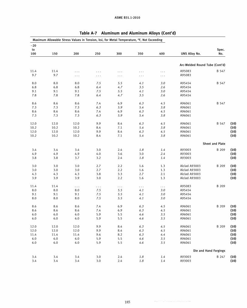
ASME B31.1-2010
Table A-7 Aluminum and Aluminum Alloys (Cont’d)
Maximum Allowable Stress Values in Tension, ksi, for Metal Temperature, °F, Not Exceeding
−20to Spec.
100 150 200 250 300 350 400 UNS Alloy No. No.
Arc-Welded Round Tube (Cont’d)
11.4 11.4 . . . . . . . . . . . . . . . A95083 B 5479.7 9.7 . . . . . . . . . . . . . . . A95083
8.0 8.0 8.0 7.5 5.5 4.1 3.0 A95454 B 5476.8 6.8 6.8 6.4 4.7 3.5 2.6 A954549.1 9.1 9.1 7.5 5.5 4.1 3.0 A954547.8 7.8 7.8 6.4 4.7 3.5 2.6 A95454
8.6 8.6 8.6 7.4 6.9 6.3 4.5 A96061 B 5477.3 7.3 7.3 6.3 5.9 5.4 3.8 A960618.6 8.6 8.6 7.4 6.9 6.3 4.5 A960617.3 7.3 7.3 6.3 5.9 5.4 3.8 A96061
(10)12.0 12.0 12.0 9.9 8.4 6.3 4.5 A96061 B 547(10)10.2 10.2 10.2 8.4 7.1 5.4 3.8 A96061(10)12.0 12.0 12.0 9.9 8.4 6.3 4.5 A96061(10)10.2 10.2 10.2 8.4 7.1 5.4 3.8 A96061
Sheet and Plate
(10)3.4 3.4 3.4 3.0 2.4 1.8 1.4 A93003 B 209(10)4.9 4.9 4.9 4.0 3.6 3.0 2.4 A93003(10)3.8 3.8 3.7 3.2 2.4 1.8 1.4 A93003
(10)3.0 3.0 3.0 2.7 2.2 1.6 1.3 Alclad A93003 B 209(10)3.0 3.0 3.0 2.7 2.2 1.6 1.3 Alclad A93003(10)4.3 4.3 4.3 3.8 3.3 2.7 2.1 Alclad A93003(10)3.9 3.9 3.9 3.0 2.2 1.6 1.3 Alclad A93003
11.4 11.4 . . . . . . . . . . . . . . . A95083 B 2098.0 8.0 8.0 7.5 5.5 4.1 3.0 A954549.1 9.1 9.1 7.5 5.5 4.1 3.0 A954548.0 8.0 8.0 7.5 5.5 4.1 3.0 A95454
(10)8.6 8.6 8.6 7.4 6.9 6.3 4.5 A96061 B 209(10)8.6 8.6 8.6 7.4 6.9 6.3 4.5 A96061(10)6.0 6.0 6.0 5.9 5.5 4.6 3.5 A96061(10)6.0 6.0 6.0 5.9 5.5 4.6 3.5 A96061
(10)12.0 12.0 12.0 9.9 8.4 6.3 4.5 A96061 B 209(10)12.0 12.0 12.0 9.9 8.4 6.3 4.5 A96061(10)11.4 11.4 11.4 9.6 8.2 6.3 4.4 A96061(10)6.0 6.0 6.0 5.9 5.5 4.6 3.5 A96061(10)6.0 6.0 6.0 5.9 5.5 4.6 3.5 A96061
Die and Hand Forgings
(10)3.4 3.4 3.4 3.0 2.4 1.8 1.4 A93003 B 247(10)3.4 3.4 3.4 3.0 2.4 1.8 1.4 A93003
185
Copyright ASME International Provided by IHS under license with ASME No reproduction or networking permitted without license from IHS
--`,,```````,,```,`,`,,,,`,`,`,`-`-`,,`,,`,`,,`---
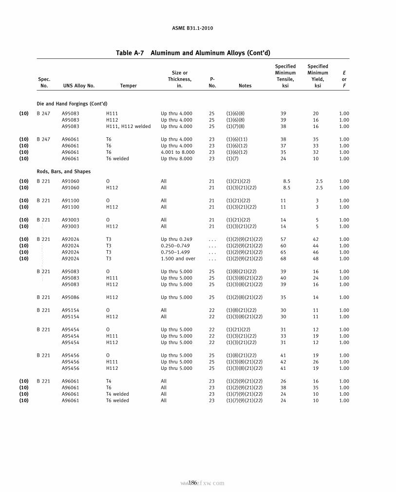
ASME B31.1-2010
Table A-7 Aluminum and Aluminum Alloys (Cont’d)
Specified SpecifiedSize or Minimum Minimum E
Spec. Thickness, P- Tensile, Yield, orNo. UNS Alloy No. Temper in. No. Notes ksi ksi F
Die and Hand Forgings (Cont’d)
(10) B 247 A95083 H111 Up thru 4.000 25 (1)(6)(8) 39 20 1.00A95083 H112 Up thru 4.000 25 (1)(6)(8) 39 16 1.00A95083 H111, H112 welded Up thru 4.000 25 (1)(7)(8) 38 16 1.00
(10) B 247 A96061 T6 Up thru 4.000 23 (1)(6)(11) 38 35 1.00(10) A96061 T6 Up thru 4.000 23 (1)(6)(12) 37 33 1.00(10) A96061 T6 4.001 to 8.000 23 (1)(6)(12) 35 32 1.00(10) A96061 T6 welded Up thru 8.000 23 (1)(7) 24 10 1.00
Rods, Bars, and Shapes
(10) B 221 A91060 O All 21 (1)(21)(22) 8.5 2.5 1.00(10) A91060 H112 All 21 (1)(3)(21)(22) 8.5 2.5 1.00
(10) B 221 A91100 O All 21 (1)(21)(22) 11 3 1.00(10) A91100 H112 All 21 (1)(3)(21)(22) 11 3 1.00
(10) B 221 A93003 O All 21 (1)(21)(22) 14 5 1.00(10) A93003 H112 All 21 (1)(3)(21)(22) 14 5 1.00
(10) B 221 A92024 T3 Up thru 0.249 . . . (1)(2)(9)(21)(22) 57 42 1.00(10) A92024 T3 0.250–0.749 . . . (1)(2)(9)(21)(22) 60 44 1.00(10) A92024 T3 0.750–1.499 . . . (1)(2)(9)(21)(22) 65 46 1.00(10) A92024 T3 1.500 and over . . . (1)(2)(9)(21)(22) 68 48 1.00
B 221 A95083 O Up thru 5.000 25 (1)(8)(21)(22) 39 16 1.00A95083 H111 Up thru 5.000 25 (1)(3)(8)(21)(22) 40 24 1.00A95083 H112 Up thru 5.000 25 (1)(3)(8)(21)(22) 39 16 1.00
B 221 A95086 H112 Up thru 5.000 25 (1)(2)(8)(21)(22) 35 14 1.00
B 221 A95154 O All 22 (1)(8)(21)(22) 30 11 1.00A95154 H112 All 22 (1)(3)(8)(21)(22) 30 11 1.00
B 221 A95454 O Up thru 5.000 22 (1)(21)(22) 31 12 1.00A95454 H111 Up thru 5.000 22 (1)(3)(21)(22) 33 19 1.00A95454 H112 Up thru 5.000 22 (1)(3)(21)(22) 31 12 1.00
B 221 A95456 O Up thru 5.000 25 (1)(8)(21)(22) 41 19 1.00A95456 H111 Up thru 5.000 25 (1)(3)(8)(21)(22) 42 26 1.00A95456 H112 Up thru 5.000 25 (1)(3)(8)(21)(22) 41 19 1.00
(10) B 221 A96061 T4 All 23 (1)(2)(9)(21)(22) 26 16 1.00(10) A96061 T6 All 23 (1)(2)(9)(21)(22) 38 35 1.00(10) A96061 T4 welded All 23 (1)(7)(9)(21)(22) 24 10 1.00(10) A96061 T6 welded All 23 (1)(7)(9)(21)(22) 24 10 1.00
186
Copyright ASME International Provided by IHS under license with ASME No reproduction or networking permitted without license from IHS
--`,,```````,,```,`,`,,,,`,`,`,`-`-`,,`,,`,`,,`---
标准分享网 www.bzfxw.com 免费下载

ASME B31.1-2010
Table A-7 Aluminum and Aluminum Alloys (Cont’d)
Maximum Allowable Stress Values in Tension, ksi, for Metal Temperature, °F, Not Exceeding
−20to Spec.
100 150 200 250 300 350 400 UNS Alloy No. No.
Die and Hand Forgings (Cont’d)
(10)11.1 11.1 . . . . . . . . . . . . . . . A95083 B 24710.7 10.7 . . . . . . . . . . . . . . . A9508310.9 10.9 . . . . . . . . . . . . . . . A95083
(10)10.9 10.9 10.9 9.1 7.9 6.3 4.5 A96061 B 247(10)10.6 10.6 10.6 8.8 7.7 6.3 4.5 A96061(10)10.0 10.0 10.0 8.4 7.4 6.1 4.5 A96061(10)6.0 6.0 6.0 5.9 5.5 4.6 3.5 A96061
Rods, Bars, and Shapes
(10)1.7 1.7 1.6 1.5 1.3 1.1 0.8 A91060 B 221(10)1.7 1.7 1.6 1.5 1.3 1.1 0.8 A91060
(10)2.0 2.0 2.0 2.0 1.8 1.4 1.0 A91100 B 221(10)2.0 2.0 2.0 2.0 1.8 1.4 1.0 A91100
(10)3.4 3.4 3.4 3.0 2.4 1.8 1.4 A93003 B 221(10)3.4 3.4 3.4 3.0 2.4 1.8 1.4 A93003
(10)16.3 16.3 16.3 12.6 9.5 6.0 4.2 A92024 B 221(10)17.1 17.1 17.1 13.2 10.0 6.3 4.4 A92024(10)18.6 18.6 18.6 14.3 10.8 6.8 4.7 A92024(10)19.4 19.4 19.4 15.0 11.3 7.1 5.0 A92024
10.7 10.7 . . . . . . . . . . . . . . . A95083 B 22111.4 11.4 . . . . . . . . . . . . . . . A9508310.7 10.7 . . . . . . . . . . . . . . . A95083
9.3 9.3 . . . . . . . . . . . . . . . A95086 B 221
7.3 7.3 . . . . . . . . . . . . . . . A95154 B 2217.3 7.3 . . . . . . . . . . . . . . . A95154
8.0 8.0 8.0 7.5 5.5 4.1 3.0 A95454 B 2219.4 9.4 9.4 7.5 5.5 4.1 3.0 A954548.0 8.0 8.0 7.5 5.5 4.1 3.0 A95454
11.7 11.7 . . . . . . . . . . . . . . . A95456 B 22112.0 12.0 . . . . . . . . . . . . . . . A9545611.7 11.7 . . . . . . . . . . . . . . . A95456
(10)7.4 7.4 7.4 6.4 6.0 5.8 4.5 A96061 B 221(10)10.9 10.9 10.9 9.1 7.9 6.3 4.5 A96061(10)6.0 6.0 6.0 5.9 5.5 4.6 3.5 A96061(10)6.0 6.0 6.0 5.9 5.5 4.6 3.5 A96061
187
Copyright ASME International Provided by IHS under license with ASME No reproduction or networking permitted without license from IHS
--`,,```````,,```,`,`,,,,`,`,`,`-`-`,,`,,`,`,,`---
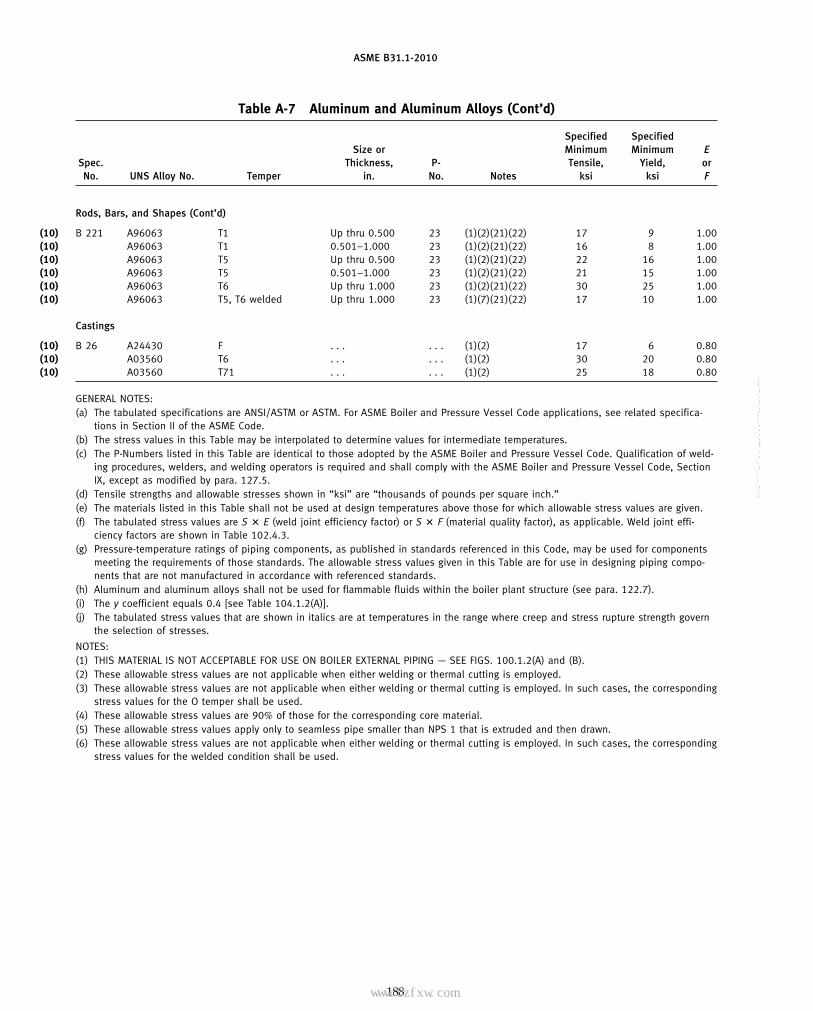
ASME B31.1-2010
Table A-7 Aluminum and Aluminum Alloys (Cont’d)
Specified SpecifiedSize or Minimum Minimum E
Spec. Thickness, P- Tensile, Yield, orNo. UNS Alloy No. Temper in. No. Notes ksi ksi F
Rods, Bars, and Shapes (Cont’d)
(10) B 221 A96063 T1 Up thru 0.500 23 (1)(2)(21)(22) 17 9 1.00(10) A96063 T1 0.501–1.000 23 (1)(2)(21)(22) 16 8 1.00(10) A96063 T5 Up thru 0.500 23 (1)(2)(21)(22) 22 16 1.00(10) A96063 T5 0.501–1.000 23 (1)(2)(21)(22) 21 15 1.00(10) A96063 T6 Up thru 1.000 23 (1)(2)(21)(22) 30 25 1.00(10) A96063 T5, T6 welded Up thru 1.000 23 (1)(7)(21)(22) 17 10 1.00
Castings
(10) B 26 A24430 F . . . . . . (1)(2) 17 6 0.80(10) A03560 T6 . . . . . . (1)(2) 30 20 0.80(10) A03560 T71 . . . . . . (1)(2) 25 18 0.80
GENERAL NOTES:(a) The tabulated specifications are ANSI/ASTM or ASTM. For ASME Boiler and Pressure Vessel Code applications, see related specifica-
tions in Section II of the ASME Code.(b) The stress values in this Table may be interpolated to determine values for intermediate temperatures.(c) The P-Numbers listed in this Table are identical to those adopted by the ASME Boiler and Pressure Vessel Code. Qualification of weld-
ing procedures, welders, and welding operators is required and shall comply with the ASME Boiler and Pressure Vessel Code, SectionIX, except as modified by para. 127.5.
(d) Tensile strengths and allowable stresses shown in “ksi” are “thousands of pounds per square inch.”(e) The materials listed in this Table shall not be used at design temperatures above those for which allowable stress values are given.(f) The tabulated stress values are S � E (weld joint efficiency factor) or S � F (material quality factor), as applicable. Weld joint effi-
ciency factors are shown in Table 102.4.3.(g) Pressure-temperature ratings of piping components, as published in standards referenced in this Code, may be used for components
meeting the requirements of those standards. The allowable stress values given in this Table are for use in designing piping compo-nents that are not manufactured in accordance with referenced standards.
(h) Aluminum and aluminum alloys shall not be used for flammable fluids within the boiler plant structure (see para. 122.7).(i) The y coefficient equals 0.4 [see Table 104.1.2(A)].(j) The tabulated stress values that are shown in italics are at temperatures in the range where creep and stress rupture strength govern
the selection of stresses.
NOTES:(1) THIS MATERIAL IS NOT ACCEPTABLE FOR USE ON BOILER EXTERNAL PIPING — SEE FIGS. 100.1.2(A) and (B).(2) These allowable stress values are not applicable when either welding or thermal cutting is employed.(3) These allowable stress values are not applicable when either welding or thermal cutting is employed. In such cases, the corresponding
stress values for the O temper shall be used.(4) These allowable stress values are 90% of those for the corresponding core material.(5) These allowable stress values apply only to seamless pipe smaller than NPS 1 that is extruded and then drawn.(6) These allowable stress values are not applicable when either welding or thermal cutting is employed. In such cases, the corresponding
stress values for the welded condition shall be used.
188
Copyright ASME International Provided by IHS under license with ASME No reproduction or networking permitted without license from IHS
--`,,```````,,```,`,`,,,,`,`,`,`-`-`,,`,,`,`,,`---
标准分享网 www.bzfxw.com 免费下载
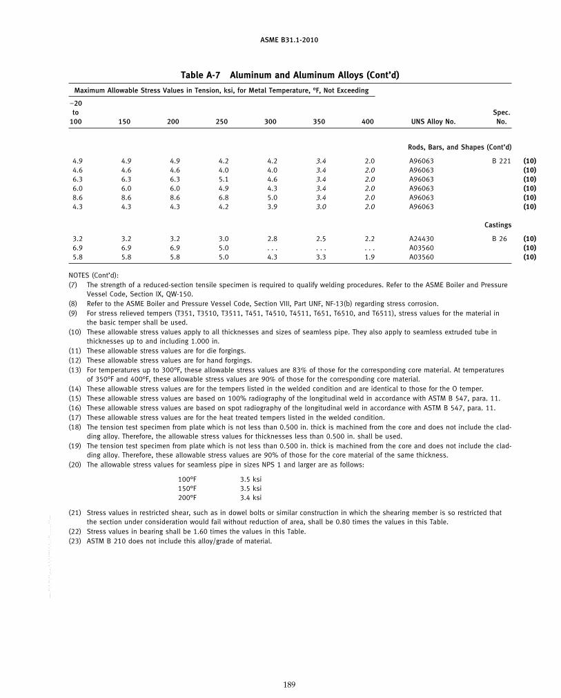
ASME B31.1-2010
Table A-7 Aluminum and Aluminum Alloys (Cont’d)
Maximum Allowable Stress Values in Tension, ksi, for Metal Temperature, °F, Not Exceeding
−20to Spec.
100 150 200 250 300 350 400 UNS Alloy No. No.
Rods, Bars, and Shapes (Cont’d)
(10)4.9 4.9 4.9 4.2 4.2 3.4 2.0 A96063 B 221(10)4.6 4.6 4.6 4.0 4.0 3.4 2.0 A96063(10)6.3 6.3 6.3 5.1 4.6 3.4 2.0 A96063(10)6.0 6.0 6.0 4.9 4.3 3.4 2.0 A96063(10)8.6 8.6 8.6 6.8 5.0 3.4 2.0 A96063(10)4.3 4.3 4.3 4.2 3.9 3.0 2.0 A96063
Castings
(10)3.2 3.2 3.2 3.0 2.8 2.5 2.2 A24430 B 26(10)6.9 6.9 6.9 5.0 . . . . . . . . . A03560(10)5.8 5.8 5.8 5.0 4.3 3.3 1.9 A03560
NOTES (Cont’d):(7) The strength of a reduced-section tensile specimen is required to qualify welding procedures. Refer to the ASME Boiler and Pressure
Vessel Code, Section IX, QW-150.(8) Refer to the ASME Boiler and Pressure Vessel Code, Section VIII, Part UNF, NF-13(b) regarding stress corrosion.(9) For stress relieved tempers (T351, T3510, T3511, T451, T4510, T4511, T651, T6510, and T6511), stress values for the material in
the basic temper shall be used.(10) These allowable stress values apply to all thicknesses and sizes of seamless pipe. They also apply to seamless extruded tube in
thicknesses up to and including 1.000 in.(11) These allowable stress values are for die forgings.(12) These allowable stress values are for hand forgings.(13) For temperatures up to 300°F, these allowable stress values are 83% of those for the corresponding core material. At temperatures
of 350°F and 400°F, these allowable stress values are 90% of those for the corresponding core material.(14) These allowable stress values are for the tempers listed in the welded condition and are identical to those for the O temper.(15) These allowable stress values are based on 100% radiography of the longitudinal weld in accordance with ASTM B 547, para. 11.(16) These allowable stress values are based on spot radiography of the longitudinal weld in accordance with ASTM B 547, para. 11.(17) These allowable stress values are for the heat treated tempers listed in the welded condition.(18) The tension test specimen from plate which is not less than 0.500 in. thick is machined from the core and does not include the clad-
ding alloy. Therefore, the allowable stress values for thicknesses less than 0.500 in. shall be used.(19) The tension test specimen from plate which is not less than 0.500 in. thick is machined from the core and does not include the clad-
ding alloy. Therefore, these allowable stress values are 90% of those for the core material of the same thickness.(20) The allowable stress values for seamless pipe in sizes NPS 1 and larger are as follows:
100°F 3.5 ksi150°F 3.5 ksi200°F 3.4 ksi
(21) Stress values in restricted shear, such as in dowel bolts or similar construction in which the shearing member is so restricted thatthe section under consideration would fail without reduction of area, shall be 0.80 times the values in this Table.
(22) Stress values in bearing shall be 1.60 times the values in this Table.(23) ASTM B 210 does not include this alloy/grade of material.
189
Copyright ASME International Provided by IHS under license with ASME No reproduction or networking permitted without license from IHS
--`,,```````,,```,`,`,,,,`,`,`,`-`-`,,`,,`,`,,`---
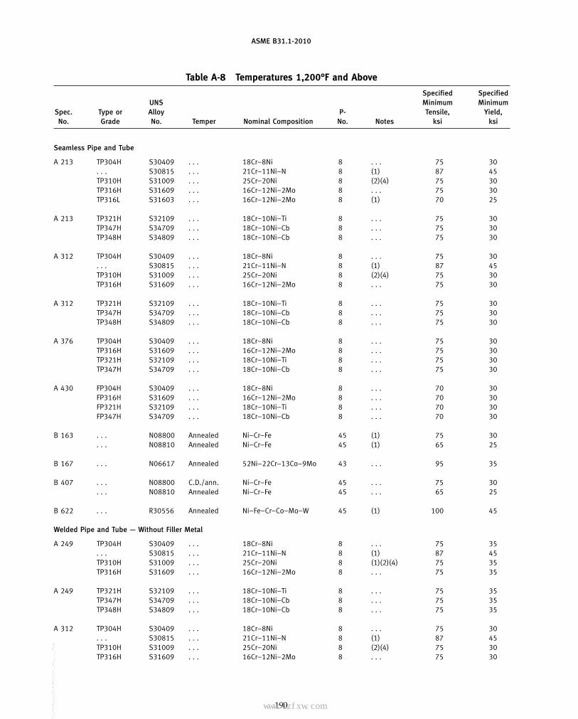
ASME B31.1-2010
Table A-8 Temperatures 1,200°F and Above
Specified SpecifiedUNS Minimum Minimum
Spec. Type or Alloy P- Tensile, Yield,No. Grade No. Temper Nominal Composition No. Notes ksi ksi
Seamless Pipe and Tube
A 213 TP304H S30409 . . . 18Cr–8Ni 8 . . . 75 30. . . S30815 . . . 21Cr–11Ni–N 8 (1) 87 45TP310H S31009 . . . 25Cr–20Ni 8 (2)(4) 75 30TP316H S31609 . . . 16Cr–12Ni–2Mo 8 . . . 75 30TP316L S31603 . . . 16Cr–12Ni–2Mo 8 (1) 70 25
A 213 TP321H S32109 . . . 18Cr–10Ni–Ti 8 . . . 75 30TP347H S34709 . . . 18Cr–10Ni–Cb 8 . . . 75 30TP348H S34809 . . . 18Cr–10Ni–Cb 8 . . . 75 30
A 312 TP304H S30409 . . . 18Cr–8Ni 8 . . . 75 30. . . S30815 . . . 21Cr–11Ni–N 8 (1) 87 45TP310H S31009 . . . 25Cr–20Ni 8 (2)(4) 75 30TP316H S31609 . . . 16Cr–12Ni–2Mo 8 . . . 75 30
A 312 TP321H S32109 . . . 18Cr–10Ni–Ti 8 . . . 75 30TP347H S34709 . . . 18Cr–10Ni–Cb 8 . . . 75 30TP348H S34809 . . . 18Cr–10Ni–Cb 8 . . . 75 30
A 376 TP304H S30409 . . . 18Cr–8Ni 8 . . . 75 30TP316H S31609 . . . 16Cr–12Ni–2Mo 8 . . . 75 30TP321H S32109 . . . 18Cr–10Ni–Ti 8 . . . 75 30TP347H S34709 . . . 18Cr–10Ni–Cb 8 . . . 75 30
A 430 FP304H S30409 . . . 18Cr–8Ni 8 . . . 70 30FP316H S31609 . . . 16Cr–12Ni–2Mo 8 . . . 70 30FP321H S32109 . . . 18Cr–10Ni–Ti 8 . . . 70 30FP347H S34709 . . . 18Cr–10Ni–Cb 8 . . . 70 30
B 163 . . . N08800 Annealed Ni–Cr–Fe 45 (1) 75 30. . . N08810 Annealed Ni–Cr–Fe 45 (1) 65 25
B 167 . . . N06617 Annealed 52Ni–22Cr–13Co–9Mo 43 . . . 95 35
B 407 . . . N08800 C.D./ann. Ni–Cr–Fe 45 . . . 75 30. . . N08810 Annealed Ni–Cr–Fe 45 . . . 65 25
B 622 . . . R30556 Annealed Ni–Fe–Cr–Co–Mo–W 45 (1) 100 45
Welded Pipe and Tube — Without Filler Metal
A 249 TP304H S30409 . . . 18Cr–8Ni 8 . . . 75 35. . . S30815 . . . 21Cr–11Ni–N 8 (1) 87 45TP310H S31009 . . . 25Cr–20Ni 8 (1)(2)(4) 75 35TP316H S31609 . . . 16Cr–12Ni–2Mo 8 . . . 75 35
A 249 TP321H S32109 . . . 18Cr–10Ni–Ti 8 . . . 75 35TP347H S34709 . . . 18Cr–10Ni–Cb 8 . . . 75 35TP348H S34809 . . . 18Cr–10Ni–Cb 8 . . . 75 35
A 312 TP304H S30409 . . . 18Cr–8Ni 8 . . . 75 30. . . S30815 . . . 21Cr–11Ni–N 8 (1) 87 45TP310H S31009 . . . 25Cr–20Ni 8 (2)(4) 75 30TP316H S31609 . . . 16Cr–12Ni–2Mo 8 . . . 75 30
190
Copyright ASME International Provided by IHS under license with ASME No reproduction or networking permitted without license from IHS
--`,,```````,,```,`,`,,,,`,`,`,`-`-`,,`,,`,`,,`---
标准分享网 www.bzfxw.com 免费下载

ASME B31.1-2010
Table A-8 Temperatures 1,200°F and Above
Maximum Allowable Stress Values in Tension, ksi, for Metal Temperature, °F, Not ExceedingE or Type or Spec.F 1,200 1,250 1,300 1,350 1,400 1,450 1,500 Grade No.
Seamless Pipe and Tube
1.00 6.1 4.7 3.7 2.9 2.3 1.8 1.4 TP304H A 2131.00 5.2 4.0 3.1 2.4 1.9 1.6 1.3 . . .1.00 4.0 3.0 2.2 1.7 1.3 0.97 0.75 TP310H1.00 7.4 5.5 4.1 3.1 2.3 1.7 1.3 TP316H1.00 6.4 4.7 3.5 2.5 1.8 1.3 1.0 TP316L
1.00 5.4 4.1 3.2 2.5 1.9 1.5 1.1 TP321H A 2131.00 7.9 5.9 4.4 3.2 2.5 1.8 1.3 TP347H1.00 7.9 5.9 4.4 3.2 2.5 1.8 1.3 TP348H
1.00 6.1 4.7 3.7 2.9 2.3 1.8 1.4 TP304H A 3121.00 5.2 4.0 3.1 2.4 1.9 1.6 1.3 . . .1.00 4.0 3.0 2.2 1.7 1.3 0.97 0.75 TP310H1.00 7.4 5.5 4.1 3.1 2.3 1.7 1.3 TP316H
1.00 5.4 4.1 3.2 2.5 1.9 1.5 1.1 TP321H A 3121.00 7.9 5.9 4.4 3.2 2.5 1.8 1.3 TP347H1.00 7.9 5.9 4.4 3.2 2.5 1.8 1.3 TP348H
1.00 6.1 4.7 3.7 2.9 2.3 1.8 1.4 TP304H A 3761.00 7.4 5.5 4.1 3.1 2.3 1.7 1.3 TP316H1.00 5.4 4.1 3.2 2.5 1.9 1.5 1.1 TP321H1.00 7.9 5.9 4.4 3.2 2.5 1.8 1.3 TP347H
1.00 6.1 4.7 3.7 2.9 2.3 1.8 1.4 FP304H A 4301.00 7.4 5.5 4.1 3.1 2.3 1.7 1.3 FP316H1.00 5.4 4.1 3.2 2.5 1.9 1.5 1.1 FP321H1.00 7.9 5.9 4.4 3.2 2.5 1.8 1.3 FP347H
1.00 6.6 4.2 2.0 1.6 1.1 1.0 0.80 . . . B 1631.00 7.4 5.9 4.7 3.8 3.0 2.4 1.9 . . .
1.00 15.3 14.5 11.2 8.7 6.6 5.1 3.9 . . . B 167
1.00 6.6 4.2 2.0 1.6 1.1 1.0 0.80 . . . B 4071.00 7.4 5.9 4.7 3.8 3.0 2.4 1.9 . . .
1.00 13.6 10.9 8.8 7.0 5.6 4.5 3.6 R30556 B 622
Welded Pipe and Tube — Without Filler Metal
0.85 5.2 4.0 3.2 2.5 2.0 1.6 1.2 TP304H A 2490.85 4.4 3.4 2.6 2.0 1.6 1.4 1.1 . . .0.85 3.4 2.6 1.9 1.4 1.1 0.82 0.64 TP310H0.85 6.3 4.7 3.5 2.6 1.9 1.5 1.1 TP316H
0.85 4.6 3.5 2.7 2.1 1.6 1.3 1.0 TP321H A 2490.85 6.7 5.0 3.7 2.7 2.1 1.6 1.1 TP347H0.85 6.7 5.0 3.7 2.7 2.1 1.6 1.1 TP348H
0.85 5.2 4.0 3.2 2.5 2.0 1.6 1.2 TP304H A 3120.85 4.4 3.4 2.6 2.0 1.6 1.4 1.1 . . .0.85 3.4 2.6 1.9 1.4 1.1 0.82 0.64 TP310H0.85 6.3 4.7 3.5 2.6 1.9 1.5 1.1 TP316H
191
Copyright ASME International Provided by IHS under license with ASME No reproduction or networking permitted without license from IHS
--`,,```````,,```,`,`,,,,`,`,`,`-`-`,,`,,`,`,,`---
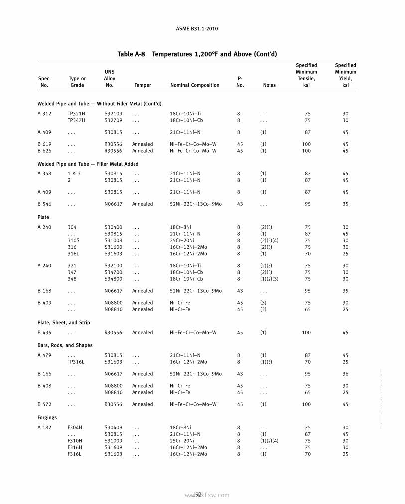
ASME B31.1-2010
Table A-8 Temperatures 1,200°F and Above (Cont’d)
Specified SpecifiedUNS Minimum Minimum
Spec. Type or Alloy P- Tensile, Yield,No. Grade No. Temper Nominal Composition No. Notes ksi ksi
Welded Pipe and Tube — Without Filler Metal (Cont’d)
A 312 TP321H S32109 . . . 18Cr–10Ni–Ti 8 . . . 75 30TP347H S32709 . . . 18Cr–10Ni–Cb 8 . . . 75 30
A 409 . . . S30815 . . . 21Cr–11Ni–N 8 (1) 87 45
B 619 . . . R30556 Annealed Ni–Fe–Cr–Co–Mo–W 45 (1) 100 45B 626 . . . R30556 Annealed Ni–Fe–Cr–Co–Mo–W 45 (1) 100 45
Welded Pipe and Tube — Filler Metal Added
A 358 1 & 3 S30815 . . . 21Cr–11Ni–N 8 (1) 87 452 S30815 . . . 21Cr–11Ni–N 8 (1) 87 45
A 409 . . . S30815 . . . 21Cr–11Ni–N 8 (1) 87 45
B 546 . . . N06617 Annealed 52Ni–22Cr–13Co–9Mo 43 . . . 95 35
Plate
A 240 304 S30400 . . . 18Cr–8Ni 8 (2)(3) 75 30. . . S30815 . . . 21Cr–11Ni–N 8 (1) 87 45310S S31008 . . . 25Cr–20Ni 8 (2)(3)(4) 75 30316 S31600 . . . 16Cr–12Ni–2Mo 8 (2)(3) 75 30316L S31603 . . . 16Cr–12Ni–2Mo 8 (1) 70 25
A 240 321 S32100 . . . 18Cr–10Ni–Ti 8 (2)(3) 75 30347 S34700 . . . 18Cr–10Ni–Cb 8 (2)(3) 75 30348 S34800 . . . 18Cr–10Ni–Cb 8 (1)(2)(3) 75 30
B 168 . . . N06617 Annealed 52Ni–22Cr–13Co–9Mo 43 . . . 95 35
B 409 . . . N08800 Annealed Ni–Cr–Fe 45 (3) 75 30. . . N08810 Annealed Ni–Cr–Fe 45 (3) 65 25
Plate, Sheet, and Strip
B 435 . . . R30556 Annealed Ni–Fe–Cr–Co–Mo–W 45 (1) 100 45
Bars, Rods, and Shapes
A 479 . . . S30815 . . . 21Cr–11Ni–N 8 (1) 87 45TP316L S31603 . . . 16Cr–12Ni–2Mo 8 (1)(5) 70 25
B 166 . . . N06617 Annealed 52Ni–22Cr–13Co–9Mo 43 . . . 95 36
B 408 . . . N08800 Annealed Ni–Cr–Fe 45 . . . 75 30. . . N08810 Annealed Ni–Cr–Fe 45 . . . 65 25
B 572 . . . R30556 Annealed Ni–Fe–Cr–Co–Mo–W 45 (1) 100 45
Forgings
A 182 F304H S30409 . . . 18Cr–8Ni 8 . . . 75 30. . . S30815 . . . 21Cr–11Ni–N 8 (1) 87 45F310H S31009 . . . 25Cr–20Ni 8 (1)(2)(4) 75 30F316H S31609 . . . 16Cr–12Ni–2Mo 8 . . . 75 30F316L S31603 . . . 16Cr–12Ni–2Mo 8 (1) 70 25
192
Copyright ASME International Provided by IHS under license with ASME No reproduction or networking permitted without license from IHS
--`,,```````,,```,`,`,,,,`,`,`,`-`-`,,`,,`,`,,`---
标准分享网 www.bzfxw.com 免费下载

ASME B31.1-2010
Table A-8 Temperatures 1,200°F and Above (Cont’d)
Maximum Allowable Stress Values in Tension, ksi, for Metal Temperature, °F, Not ExceedingE or Type or Spec.F 1,200 1,250 1,300 1,350 1,400 1,450 1,500 Grade No.
Welded Pipe and Tube — Without Filler Metal (Cont’d)
0.85 4.6 3.5 2.7 2.1 1.6 1.3 1.0 TP321H A 3120.85 6.7 5.0 3.7 2.7 2.1 1.6 1.1 TP347H
0.85 4.4 3.4 2.6 2.0 1.6 1.4 1.1 . . . A 409
0.85 11.6 9.3 7.5 6.0 4.8 3.8 3.1 R30556 B 6190.85 11.6 9.3 7.5 6.0 4.8 3.8 3.1 R30556 B 626
Welded Pipe and Tube — Filler Metal Added
1.00 5.2 4.0 3.1 2.4 1.9 1.6 1.3 1 & 3 A 3580.90 4.7 3.6 2.8 2.2 1.7 1.4 1.2 2
0.80 4.2 3.2 2.5 1.9 1.5 1.3 1.0 . . . A 409
0.85 13.0 12.3 9.5 7.4 5.6 4.3 3.3 . . . B 546
Plate
1.00 6.1 4.7 3.7 2.9 2.3 1.8 1.4 304 A 2401.00 5.2 4.0 3.1 2.4 1.9 1.6 1.3 . . .1.00 2.5 1.5 0.80 0.50 0.40 0.30 0.20 310S1.00 7.4 5.5 4.1 3.1 2.3 1.7 1.3 3161.00 6.4 4.7 3.5 2.5 1.8 1.3 1.0 316L
1.00 3.6 2.6 1.7 1.1 0.80 0.50 0.30 321 A 2401.00 4.4 3.3 2.2 1.5 1.2 0.90 0.80 3471.00 4.4 3.3 2.2 1.5 1.2 0.90 0.80 348
1.00 15.3 14.5 11.2 8.7 6.6 5.1 3.9 . . . B 168
1.00 6.6 4.2 2.0 1.6 1.1 1.0 0.80 . . . B 4091.00 7.4 5.9 4.7 3.8 3.0 2.4 1.9 . . .
Plate, Sheet, and Strip
1.00 13.6 10.9 8.8 7.0 5.6 4.5 3.6 R30556 B 435
Bars, Rods, and Shapes
1.00 5.2 4.0 3.1 2.4 1.9 1.6 1.3 . . . A 4791.00 6.4 4.7 3.5 2.5 1.8 1.3 1.0 TP316L
1.00 15.3 14.5 11.2 8.7 6.6 5.1 3.9 . . . B 166
1.00 6.6 4.2 2.0 1.6 1.1 1.0 0.80 . . . B 4081.00 7.4 5.9 4.7 3.8 3.0 2.4 1.9 . . .
1.00 13.6 10.9 8.8 7.0 5.6 4.5 3.6 R30556 B 572
Forgings
1.00 6.1 4.7 3.7 2.9 2.3 1.8 1.4 F304H A 1821.00 5.2 4.0 3.1 2.4 1.9 1.6 1.3 . . .1.00 4.0 3.0 2.2 1.7 1.3 0.97 0.75 F310H1.00 7.4 5.5 4.1 3.1 2.3 1.7 1.3 F316H1.00 6.4 4.7 3.5 2.5 1.8 1.3 1.0 F316L
193
Copyright ASME International Provided by IHS under license with ASME No reproduction or networking permitted without license from IHS
--`,,```````,,```,`,`,,,,`,`,`,`-`-`,,`,,`,`,,`---
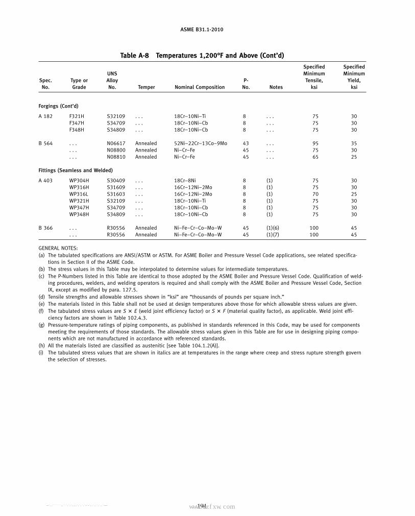
ASME B31.1-2010
Table A-8 Temperatures 1,200°F and Above (Cont’d)
Specified SpecifiedUNS Minimum Minimum
Spec. Type or Alloy P- Tensile, Yield,No. Grade No. Temper Nominal Composition No. Notes ksi ksi
Forgings (Cont’d)
A 182 F321H S32109 . . . 18Cr–10Ni–Ti 8 . . . 75 30F347H S34709 . . . 18Cr–10Ni–Cb 8 . . . 75 30F348H S34809 . . . 18Cr–10Ni–Cb 8 . . . 75 30
B 564 . . . N06617 Annealed 52Ni–22Cr–13Co–9Mo 43 . . . 95 35. . . N08800 Annealed Ni–Cr–Fe 45 . . . 75 30. . . N08810 Annealed Ni–Cr–Fe 45 . . . 65 25
Fittings (Seamless and Welded)
A 403 WP304H S30409 . . . 18Cr–8Ni 8 (1) 75 30WP316H S31609 . . . 16Cr–12Ni–2Mo 8 (1) 75 30WP316L S31603 . . . 16Cr–12Ni–2Mo 8 (1) 70 25WP321H S32109 . . . 18Cr–10Ni–Ti 8 (1) 75 30WP347H S34709 . . . 18Cr–10Ni–Cb 8 (1) 75 30WP348H S34809 . . . 18Cr–10Ni–Cb 8 (1) 75 30
B 366 . . . R30556 Annealed Ni–Fe–Cr–Co–Mo–W 45 (1)(6) 100 45. . . R30556 Annealed Ni–Fe–Cr–Co–Mo–W 45 (1)(7) 100 45
GENERAL NOTES:(a) The tabulated specifications are ANSI/ASTM or ASTM. For ASME Boiler and Pressure Vessel Code applications, see related specifica-
tions in Section II of the ASME Code.(b) The stress values in this Table may be interpolated to determine values for intermediate temperatures.(c) The P-Numbers listed in this Table are identical to those adopted by the ASME Boiler and Pressure Vessel Code. Qualification of weld-
ing procedures, welders, and welding operators is required and shall comply with the ASME Boiler and Pressure Vessel Code, SectionIX, except as modified by para. 127.5.
(d) Tensile strengths and allowable stresses shown in “ksi” are “thousands of pounds per square inch.”(e) The materials listed in this Table shall not be used at design temperatures above those for which allowable stress values are given.(f) The tabulated stress values are S � E (weld joint efficiency factor) or S � F (material quality factor), as applicable. Weld joint effi-
ciency factors are shown in Table 102.4.3.(g) Pressure-temperature ratings of piping components, as published in standards referenced in this Code, may be used for components
meeting the requirements of those standards. The allowable stress values given in this Table are for use in designing piping compo-nents which are not manufactured in accordance with referenced standards.
(h) All the materials listed are classified as austenitic [see Table 104.1.2(A)].(i) The tabulated stress values that are shown in italics are at temperatures in the range where creep and stress rupture strength govern
the selection of stresses.
194
Copyright ASME International Provided by IHS under license with ASME No reproduction or networking permitted without license from IHS
--`,,```````,,```,`,`,,,,`,`,`,`-`-`,,`,,`,`,,`--- 标准分享网 www.bzfxw.com 免费下载
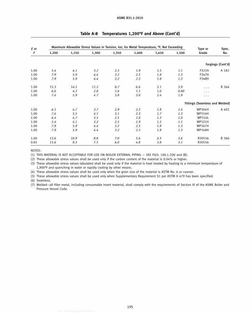
ASME B31.1-2010
Table A-8 Temperatures 1,200°F and Above (Cont’d)
Maximum Allowable Stress Values in Tension, ksi, for Metal Temperature, °F, Not ExceedingE or Type or Spec.F 1,200 1,250 1,300 1,350 1,400 1,450 1,500 Grade No.
Forgings (Cont’d)
1.00 5.4 4.1 3.2 2.5 1.9 1.5 1.1 F321H A 1821.00 7.9 5.9 4.4 3.2 2.5 1.8 1.3 F347H1.00 7.9 5.9 4.4 3.2 2.5 1.8 1.3 F348H
1.00 15.3 14.5 11.2 8.7 6.6 5.1 3.9 . . . B 5641.00 6.6 4.2 2.0 1.6 1.1 1.0 0.80 . . .1.00 7.4 5.9 4.7 3.8 3.0 2.4 1.9 . . .
Fittings (Seamless and Welded)
1.00 6.1 4.7 3.7 2.9 2.3 1.8 1.4 WP304H A 4031.00 7.4 5.5 4.1 3.1 2.3 1.7 1.3 WP316H1.00 6.4 4.7 3.5 2.5 1.8 1.3 1.0 WP316L1.00 5.4 4.1 3.2 2.5 1.9 1.5 1.1 WP321H1.00 7.9 5.9 4.4 3.2 2.5 1.8 1.3 WP347H1.00 7.9 5.9 4.4 3.2 2.5 1.8 1.3 WP348H
1.00 13.6 10.9 8.8 7.0 5.6 4.5 3.6 R30556 B 3660.85 11.6 9.3 7.5 6.0 4.8 3.8 3.1 R30556
NOTES:(1) THIS MATERIAL IS NOT ACCEPTABLE FOR USE ON BOILER EXTERNAL PIPING — SEE FIGS. 100.1.2(A) and (B).(2) These allowable stress values shall be used only if the carbon content of the material is 0.04% or higher.(3) These allowable stress values tabulated shall be used only if the material is heat treated by heating to a minimum temperature of
1,900°F and quenching in water or rapidly cooling by other means.(4) These allowable stress values shall be used only when the grain size of the material is ASTM No. 6 or coarser.(5) These allowable stress values shall be used only when Supplementary Requirement S1 per ASTM A 479 has been specified.(6) Seamless.(7) Welded—all filler metal, including consumable insert material, shall comply with the requirements of Section IX of the ASME Boiler and
Pressure Vessel Code.
195
Copyright ASME International Provided by IHS under license with ASME No reproduction or networking permitted without license from IHS
--`,,```````,,```,`,`,,,,`,`,`,`-`-`,,`,,`,`,,`---

ASME B31.1-2010
Table A-9 Titanium and Titanium Alloys
Specified SpecifiedMinimum Minimum E
Spec. Nominal P- Tensile, Yield, orNo. Grade Condition Composition No. Notes ksi ksi F
Seamless Pipe and Tube
B 338 1 Annealed Ti 51 (1) 35 25 1.002 Annealed Ti 51 (1) 50 40 1.003 Annealed Ti 52 (1) 65 55 1.007 Annealed Ti–Pd 51 (1) 50 40 1.00
12 Annealed Ti–Mo–Ni 52 (1) 70 50 1.00
B 861 1 Annealed Ti 51 (1) 35 25 1.002 Annealed Ti 51 (1) 50 40 1.003 Annealed Ti 52 (1) 65 55 1.007 Annealed Ti–Pd 51 (1) 50 40 1.00
12 Annealed Ti–Mo–Ni 52 (1) 70 50 1.00
Welded Pipe and Tube
B 338 1 Annealed Ti 51 (1)(2) 35 25 0.852 Annealed Ti 51 (1)(2) 50 40 0.853 Annealed Ti 52 (1)(2) 65 55 0.857 Annealed Ti–Pd 51 (1)(2) 50 40 0.85
12 Annealed Ti–Mo–Ni 52 (1)(2) 70 50 0.85
B 862 1 Annealed Ti 51 (1)(2) 35 25 0.852 Annealed Ti 51 (1)(2) 50 40 0.853 Annealed Ti 52 (1)(2) 65 55 0.857 Annealed Ti–Pd 51 (1)(2) 50 40 0.85
12 Annealed Ti–Mo–Ni 52 (1)(2) 70 50 0.85
Plate, Sheet, and Strip
B 265 1 Annealed Ti 51 (1) 35 25 1.002 Annealed Ti 51 (1) 50 40 1.003 Annealed Ti 52 (1) 65 55 1.007 Annealed Ti–Pd 51 (1) 50 40 1.00
12 Annealed Ti–Mo–Ni 52 (1) 70 50 1.00
Forgings
B 381 F1 Annealed Ti 51 (1) 35 25 1.00F2 Annealed Ti 51 (1) 50 40 1.00F3 Annealed Ti 52 (1) 65 55 1.00F7 Annealed Ti–Pd 51 (1) 50 40 1.00F12 Annealed Ti–Mo–Ni 52 (1) 70 50 1.00
196
Copyright ASME International Provided by IHS under license with ASME No reproduction or networking permitted without license from IHS
--`,,```````,,```,`,`,,,,`,`,`,`-`-`,,`,,`,`,,`---
标准分享网 www.bzfxw.com 免费下载

ASME B31.1-2010
Table A-9 Titanium and Titanium Alloys
Maximum Allowable Stress Values in Tension, ksi, for Metal Temperature, °F, Not Exceeding
−20to Spec.
100 150 200 250 300 350 400 450 500 550 600 Grade No.
Seamless Pipe and Tube
10.0 9.3 8.3 7.4 6.6 6.0 5.5 5.1 4.7 4.2 3.6 1 B 33814.3 13.7 12.4 11.3 10.3 9.5 8.8 8.2 7.6 7.0 6.5 218.6 17.5 15.8 14.2 12.8 11.5 10.3 9.3 8.5 7.9 7.4 314.3 13.7 12.4 11.3 10.3 9.5 8.8 8.2 7.6 7.0 6.5 720.0 20.0 18.7 17.4 16.2 15.2 14.3 13.6 13.1 12.7 12.3 12
10.0 9.3 8.3 7.4 6.6 6.0 5.5 5.1 4.7 4.2 3.6 1 B 86114.3 13.7 12.4 11.3 10.3 9.5 8.8 8.2 7.6 7.0 6.5 218.6 17.5 15.8 14.2 12.8 11.5 10.3 9.3 8.5 7.9 7.4 314.3 13.7 12.4 11.3 10.3 9.5 8.8 8.2 7.6 7.0 6.5 720.0 20.0 18.7 17.4 16.2 15.2 14.3 13.6 13.1 12.7 12.3 12
Welded Pipe and Tube
8.5 7.9 7.0 6.3 5.6 5.1 4.7 4.3 4.0 3.6 3.0 1 B 33812.1 11.6 10.6 9.6 8.8 8.1 7.5 7.0 6.5 6.0 5.5 215.8 14.9 13.4 12.1 10.8 9.7 8.8 7.9 7.2 6.7 6.3 312.1 11.6 10.6 9.6 8.8 8.1 7.5 7.0 6.5 6.0 5.5 717.0 17.0 15.9 14.8 13.8 12.9 12.1 11.5 11.1 10.8 10.5 12
8.5 7.9 7.0 6.3 5.6 5.1 4.7 4.3 4.0 3.6 3.0 1 B 86212.1 11.6 10.6 9.6 8.8 8.1 7.5 7.0 6.5 6.0 5.5 215.8 14.9 13.4 12.1 10.8 9.7 8.8 7.9 7.2 6.7 6.3 312.1 11.6 10.6 9.6 8.8 8.1 7.5 7.0 6.5 6.0 5.5 717.0 17.0 15.9 14.8 13.8 12.9 12.1 11.5 11.1 10.8 10.5 12
Plate, Sheet, and Strip
10.0 9.3 8.3 7.4 6.6 6.0 5.5 5.1 4.7 4.2 3.6 1 B 26514.3 13.7 12.4 11.3 10.3 9.5 8.8 8.2 7.6 7.0 6.5 218.6 17.5 15.8 14.2 12.8 11.5 10.3 9.3 8.5 7.9 7.4 314.3 13.7 12.4 11.3 10.3 9.5 8.8 8.2 7.6 7.0 6.5 720.0 20.0 18.7 17.4 16.2 15.2 14.3 13.6 13.1 12.7 12.3 12
Forgings
10.0 9.3 8.3 7.4 6.6 6.0 5.5 5.1 4.7 4.2 3.6 F1 B 38114.3 13.7 12.4 11.3 10.3 9.5 8.8 8.2 7.6 7.0 6.5 F218.6 17.5 15.8 14.2 12.8 11.5 10.3 9.3 8.5 7.9 7.4 F314.3 13.7 12.4 11.3 10.3 9.5 8.8 8.2 7.6 7.0 6.5 F720.0 20.0 18.7 17.4 16.2 15.2 14.3 13.6 13.1 12.7 12.3 F12
197
Copyright ASME International Provided by IHS under license with ASME No reproduction or networking permitted without license from IHS
--`,,```````,,```,`,`,,,,`,`,`,`-`-`,,`,,`,`,,`---
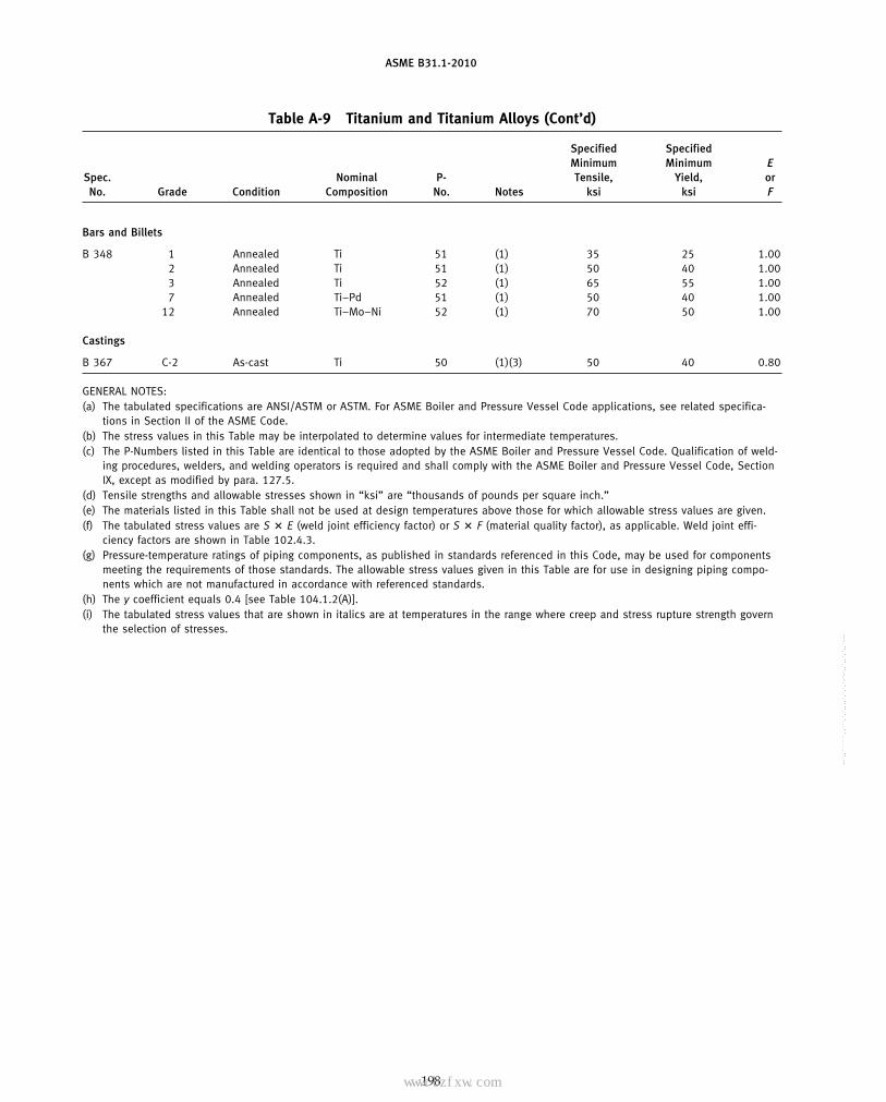
ASME B31.1-2010
Table A-9 Titanium and Titanium Alloys (Cont’d)
Specified SpecifiedMinimum Minimum E
Spec. Nominal P- Tensile, Yield, orNo. Grade Condition Composition No. Notes ksi ksi F
Bars and Billets
B 348 1 Annealed Ti 51 (1) 35 25 1.002 Annealed Ti 51 (1) 50 40 1.003 Annealed Ti 52 (1) 65 55 1.007 Annealed Ti–Pd 51 (1) 50 40 1.00
12 Annealed Ti–Mo–Ni 52 (1) 70 50 1.00
Castings
B 367 C-2 As-cast Ti 50 (1)(3) 50 40 0.80
GENERAL NOTES:(a) The tabulated specifications are ANSI/ASTM or ASTM. For ASME Boiler and Pressure Vessel Code applications, see related specifica-
tions in Section II of the ASME Code.(b) The stress values in this Table may be interpolated to determine values for intermediate temperatures.(c) The P-Numbers listed in this Table are identical to those adopted by the ASME Boiler and Pressure Vessel Code. Qualification of weld-
ing procedures, welders, and welding operators is required and shall comply with the ASME Boiler and Pressure Vessel Code, SectionIX, except as modified by para. 127.5.
(d) Tensile strengths and allowable stresses shown in “ksi” are “thousands of pounds per square inch.”(e) The materials listed in this Table shall not be used at design temperatures above those for which allowable stress values are given.(f) The tabulated stress values are S � E (weld joint efficiency factor) or S � F (material quality factor), as applicable. Weld joint effi-
ciency factors are shown in Table 102.4.3.(g) Pressure-temperature ratings of piping components, as published in standards referenced in this Code, may be used for components
meeting the requirements of those standards. The allowable stress values given in this Table are for use in designing piping compo-nents which are not manufactured in accordance with referenced standards.
(h) The y coefficient equals 0.4 [see Table 104.1.2(A)].(i) The tabulated stress values that are shown in italics are at temperatures in the range where creep and stress rupture strength govern
the selection of stresses.
198
Copyright ASME International Provided by IHS under license with ASME No reproduction or networking permitted without license from IHS
--`,,```````,,```,`,`,,,,`,`,`,`-`-`,,`,,`,`,,`---
标准分享网 www.bzfxw.com 免费下载

ASME B31.1-2010
Table A-9 Titanium and Titanium Alloys (Cont’d)
Maximum Allowable Stress Values in Tension, ksi, for Metal Temperature, °F, Not Exceeding
−20to Spec.
100 150 200 250 300 350 400 450 500 550 600 Grade No.
Bars and Billets
10.0 9.3 8.3 7.4 6.6 6.0 5.5 5.1 4.7 4.2 3.6 1 B 34814.3 13.7 12.4 11.3 10.3 9.5 8.8 8.2 7.6 7.0 6.5 218.6 17.5 15.8 14.2 12.8 11.5 10.3 9.3 8.5 7.9 7.4 314.3 13.7 12.4 11.3 10.3 9.5 8.8 8.2 7.6 7.0 6.5 720.0 20.0 18.7 17.4 16.2 15.2 14.3 13.6 13.1 12.7 12.3 12
Castings
11.4 10.5 10.0 9.0 8.3 7.6 . . . . . . . . . . . . . . . C-2 B 367
NOTES:(1) THIS MATERIAL IS NOT ACCEPTABLE FOR USE ON BOILER EXTERNAL PIPING — SEE FIGS. 100.1.2(A) and (B).(2) Filler metal shall not be used in the manufacture of welded pipe or tubing.(3) Welding of this material is not permitted.
199
Copyright ASME International Provided by IHS under license with ASME No reproduction or networking permitted without license from IHS
--`,,```````,,```,`,`,,,,`,`,`,`-`-`,,`,,`,`,,`---
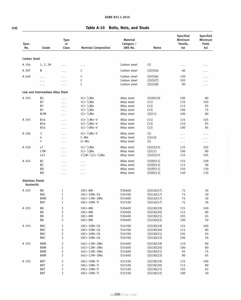
ASME B31.1-2010
(10) Table A-10 Bolts, Nuts, and Studs
Specified SpecifiedType Material Minimum Minimum
Spec. or Category / Tensile, Yield,No. Grade Class Nominal Composition UNS No. Notes ksi ksi
Carbon Steel
A 194 1, 2, 2H . . . . . . Carbon steel (1) . . . . . .
A 307 B . . . C Carbon steel (2)(3)(4) 60 . . .
A 449 . . . . . . C Carbon steel (2)(5)(6) 120 . . .. . . . . . C Carbon steel (2)(5)(7) 105 . . .. . . . . . C Carbon steel (2)(5)(8) 90 . . .
Low and Intermediate Alloy Steel
A 193 B5 . . . 5Cr–1⁄2Mo Alloy steel (5)(9)(10) 100 80B7 . . . 1Cr–1⁄5Mo Alloy steel (11) 125 105B7 . . . 1Cr–1⁄5Mo Alloy steel (12) 115 95B7 . . . 1Cr–1⁄5Mo Alloy steel (13) 100 75B7M . . . 1Cr–1⁄5Mo Alloy steel (2)(11) 100 80
A 193 B16 . . . 1Cr–1⁄2Mo–V Alloy steel (11) 125 105B16 . . . 1Cr–1⁄2Mo–V Alloy steel (12) 110 95B16 . . . 1Cr–1⁄2Mo–V Alloy steel (13) 100 85
A 194 3 . . . 5Cr–1⁄2Mo–V Alloy steel (1) . . . . . .4 . . . C–Mo Alloy steel (1)(14) . . . . . .7 . . . Cr–Mo Alloy steel (1) . . . . . .
A 320 L7 . . . 1Cr–1⁄5Mo Alloy steel (2)(5)(15) 125 105L7M . . . 1Cr–1⁄5Mo Alloy steel (2)(11) 100 80L43 . . . 13⁄4Ni–3⁄4Cr–1⁄4Mo Alloy steel (2)(5)(15) 125 105
A 354 BC . . . . . . Alloy steel (5)(9)(11) 125 109BC . . . . . . Alloy steel (5)(9)(12) 115 99BD . . . . . . Alloy steel (5)(9)(11) 150 130BD . . . . . . Alloy steel (5)(9)(12) 140 120
Stainless SteelsAustenitic
A 193 B8 1 18Cr–8Ni S30400 (5)(16)(17) 75 30B8C 1 18Cr–10Ni–Cb S34700 (5)(16)(17) 75 30B8M 1 16Cr–12Ni–2Mo S31600 (5)(16)(17) 75 30B8T 1 18Cr–10Ni–Ti S32100 (5)(16)(17) 75 30
A 193 B8 2 18Cr–8Ni S30400 (5)(18)(19) 125 100B8 2 18Cr–8Ni S30400 (5)(18)(20) 115 80B8 2 18Cr–8Ni S30400 (5)(18)(21) 105 65B8 2 18Cr–8Ni S30400 (5)(18)(22) 100 50
A 193 B8C 2 18Cr–10Ni–Cb S34700 (5)(18)(19) 125 100B8C 2 18Cr–10Ni–Cb S34700 (5)(18)(20) 115 80B8C 2 18Cr–10Ni–Cb S34700 (5)(18)(21) 105 65B8C 2 18Cr–10Ni–Cb S34700 (5)(18)(22) 100 50
A 193 B8M 2 16Cr–12Ni–2Mo S31600 (5)(18)(19) 110 80B8M 2 16Cr–12Ni–2Mo S31600 (5)(18)(20) 100 80B8M 2 16Cr–12Ni–2Mo S31600 (5)(18)(21) 95 75B8M 2 16Cr–12Ni–2Mo S31600 (5)(18)(22) 90 65
A 193 B8T 2 18Cr–10Ni–Ti S32100 (5)(18)(19) 125 100B8T 2 18Cr–10Ni–Ti S32100 (5)(18)(20) 115 80B8T 2 18Cr–10Ni–Ti S32100 (5)(18)(21) 105 65B8T 2 18Cr–10Ni–Ti S32100 (5)(18)(22) 100 50
200
Copyright ASME International Provided by IHS under license with ASME No reproduction or networking permitted without license from IHS
--`,,```````,,```,`,`,,,,`,`,`,`-`-`,,`,,`,`,,`---
标准分享网 www.bzfxw.com 免费下载

ASME B31.1-2010
(10)Table A-10 Bolts, Nuts, and Studs
Maximum Allowable Stress Values in Tension, ksi, for Metal Temperature, °F, Not Exceeding
−20to Spec.
100 200 300 350 400 450 500 600 650 700 750 800 850 900 950 1,000 1,050 1,100 1,150 1,200 Grade No.
Carbon Steel
. . . . . . . . . . . . . . . . . . . . . . . . . . . . . . . . . . . . . . . . . . . . . . . . . . . . . . . . . . . . 1, 2, 2H A 194
7.0 7.0 7.0 . . . 7.0 . . . . . . . . . . . . . . . . . . . . . . . . . . . . . . . . . . . . . . . . . . . . . B A 307
23.0 23.0 23.0 . . . 23.0 . . . 23.0 23.0 . . . . . . . . . . . . . . . . . . . . . . . . . . . . . . . . . . . . . . . A 44920.2 20.2 20.2 . . . 20.2 . . . 20.2 20.2 . . . . . . . . . . . . . . . . . . . . . . . . . . . . . . . . . . . . . . .14.5 14.5 14.5 . . . 14.5 . . . 14.5 14.5 . . . . . . . . . . . . . . . . . . . . . . . . . . . . . . . . . . . . . . .
Low and Intermediate Alloy Steel
20.0 20.0 20.0 . . . 20.0 . . . 20.0 20.0 20.0 20.0 20.0 18.5 14.5 10.4 7.6 5.6 4.2 3.1 2.0 1.3 B5 A 19325.0 25.0 25.0 . . . 25.0 . . . 25.0 25.0 25.0 25.0 23.6 21.0 16.3 12.5 8.5 4.5 . . . . . . . . . . . . B723.0 23.0 23.0 . . . 23.0 . . . 23.0 23.0 23.0 23.0 22.2 20.0 16.3 12.5 8.5 4.5 . . . . . . . . . . . . B718.8 18.8 18.8 . . . 18.8 . . . 18.8 18.8 18.8 18.8 18.8 18.0 16.3 12.5 8.5 4.5 . . . . . . . . . . . . B720.0 20.0 20.0 . . . 20.0 . . . 20.0 20.0 20.0 20.0 20.0 18.5 16.5 12.5 8.5 4.5 . . . . . . . . . . . . B7M
25.0 25.0 25.0 . . . 25.0 . . . 25.0 25.0 25.0 25.0 25.0 25.0 23.5 20.5 16.0 11.0 6.3 2.8 . . . . . . B16 A 19322.0 22.0 22.0 . . . 22.0 . . . 22.0 22.0 22.0 22.0 22.0 22.0 21.0 18.5 15.3 11.0 6.3 2.8 . . . . . . B1620.0 20.0 20.0 . . . 20.0 . . . 20.0 20.0 20.0 20.0 20.0 20.0 18.8 16.7 14.3 11.0 6.3 2.8 . . . . . . B16
. . . . . . . . . . . . . . . . . . . . . . . . . . . . . . . . . . . . . . . . . . . . . . . . . . . . . . . . . . . . 3 A 194
. . . . . . . . . . . . . . . . . . . . . . . . . . . . . . . . . . . . . . . . . . . . . . . . . . . . . . . . . . . . 4
. . . . . . . . . . . . . . . . . . . . . . . . . . . . . . . . . . . . . . . . . . . . . . . . . . . . . . . . . . . . 7
25.0 25.0 25.0 . . . 25.0 . . . 25.0 25.0 25.0 25.0 . . . . . . . . . . . . . . . . . . . . . . . . . . . . . . L7 A 32020.0 20.0 20.0 . . . 20.0 . . . 20.0 20.0 20.0 20.0 20.0 18.5 16.3 12.5 8.5 4.5 . . . . . . . . . . . . L7M25.0 25.0 25.0 . . . 25.0 . . . 25.0 25.0 25.0 25.0 . . . . . . . . . . . . . . . . . . . . . . . . . . . . . . L43
25.0 25.0 25.0 . . . 25.0 . . . 25.0 25.0 25.0 . . . . . . . . . . . . . . . . . . . . . . . . . . . . . . . . . BC A 35423.0 23.0 23.0 . . . 23.0 . . . 23.0 23.0 23.0 . . . . . . . . . . . . . . . . . . . . . . . . . . . . . . . . . BC30.0 30.0 30.0 . . . 30.0 . . . 30.0 30.0 30.0 . . . . . . . . . . . . . . . . . . . . . . . . . . . . . . . . . BD28.0 28.0 28.0 . . . 28.0 . . . 28.0 28.0 28.0 . . . . . . . . . . . . . . . . . . . . . . . . . . . . . . . . . BD
Stainless SteelsAustenitic
18.8 16.7 15.0 . . . 13.8 . . . 12.9 12.1 12.0 11.8 11.5 11.2 11.0 10.8 10.6 10.4 10.1 9.8 7.7 6.1 B8 A 19318.8 17.9 16.4 . . . 15.5 . . . 15.0 14.3 14.1 13.8 13.7 13.6 13.5 13.5 13.4 13.4 12.1 9.1 6.1 4.4 B8C18.8 17.7 15.6 . . . 14.3 . . . 13.3 12.6 12.3 12.1 11.9 11.7 11.6 11.5 11.4 11.3 11.2 11.0 9.8 7.4 B8M18.8 17.8 16.5 . . . 15.3 . . . 14.3 13.5 13.3 12.9 12.7 12.5 12.4 12.3 12.1 12.0 9.6 6.9 5.0 3.6 B8T
25.0 . . . . . . . . . . . . . . . . . . . . . . . . . . . . . . . . . . . . . . . . . . . . . . . . . . . . . . . . . B8 A 19320.0 . . . . . . . . . . . . . . . . . . . . . . . . . . . . . . . . . . . . . . . . . . . . . . . . . . . . . . . . . B818.8 . . . . . . . . . . . . . . . . . . . . . . . . . . . . . . . . . . . . . . . . . . . . . . . . . . . . . . . . . B818.8 . . . . . . . . . . . . . . . . . . . . . . . . . . . . . . . . . . . . . . . . . . . . . . . . . . . . . . . . . B8
25.0 . . . . . . . . . . . . . . . . . . . . . . . . . . . . . . . . . . . . . . . . . . . . . . . . . . . . . . . . . B8C A 19320.0 . . . . . . . . . . . . . . . . . . . . . . . . . . . . . . . . . . . . . . . . . . . . . . . . . . . . . . . . . B8C18.8 . . . . . . . . . . . . . . . . . . . . . . . . . . . . . . . . . . . . . . . . . . . . . . . . . . . . . . . . . B8C18.8 . . . . . . . . . . . . . . . . . . . . . . . . . . . . . . . . . . . . . . . . . . . . . . . . . . . . . . . . . B8C
22.0 22.0 22.0 . . . 22.0 . . . 22.0 22.0 22.0 22.0 22.0 . . . . . . . . . . . . . . . . . . . . . . . . . . . B8M A 19320.0 20.0 20.0 . . . 20.0 . . . 20.0 20.0 20.0 20.0 20.0 . . . . . . . . . . . . . . . . . . . . . . . . . . . B8M18.8 17.7 16.3 . . . 16.3 . . . 16.3 16.3 16.3 16.3 16.3 . . . . . . . . . . . . . . . . . . . . . . . . . . . B8M18.8 17.7 15.6 . . . 14.3 . . . 13.3 12.5 12.5 12.5 12.5 . . . . . . . . . . . . . . . . . . . . . . . . . . . B8M
25.0 . . . . . . . . . . . . . . . . . . . . . . . . . . . . . . . . . . . . . . . . . . . . . . . . . . . . . . . . . B8T A 19320.0 . . . . . . . . . . . . . . . . . . . . . . . . . . . . . . . . . . . . . . . . . . . . . . . . . . . . . . . . . B8T18.8 . . . . . . . . . . . . . . . . . . . . . . . . . . . . . . . . . . . . . . . . . . . . . . . . . . . . . . . . . B8T18.8 . . . . . . . . . . . . . . . . . . . . . . . . . . . . . . . . . . . . . . . . . . . . . . . . . . . . . . . . . B8T
201
Copyright ASME International Provided by IHS under license with ASME No reproduction or networking permitted without license from IHS
--`,,```````,,```,`,`,,,,`,`,`,`-`-`,,`,,`,`,,`---

ASME B31.1-2010
(10) Table A-10 Bolts, Nuts, and Studs (Cont’d)
Specified SpecifiedType Material Minimum Minimum
Spec. or Category / Tensile, Yield,No. Grade Class Nominal Composition UNS No. Notes ksi ksi
Stainless Steels (Cont’d)Austenitic (Cont’d)
A 194 8 . . . 18Cr–8Ni S30400 (1) . . . . . .8C . . . 18Cr–10Ni–Cb S34700 (1) . . . . . .
A 194 8M . . . 16Cr–12Ni–Mo S31600 (1) . . . . . .8T . . . 18Cr–10Ni–Ti S32100 (1) . . . . . .8F . . . 18Cr–8Ni–Fm . . . (1) . . . . . .
A 320 B8 1 18Cr–8Ni S30400 (5)(18) 75 30B8 1 18Cr–8Ni S30400 (5)(23) 75 30B8 2 18Cr–8Ni S30400 (5)(18)(22) 100 50B8 2 18Cr–8Ni S30400 (5)(18)(21) 105 65B8 2 18Cr–8Ni S30400 (5)(18)(20) 115 80B8 2 18Cr–8Ni S30400 (5)(18)(19) 125 100
A 320 B8C 1 18Cr–10Ni–Cb S34700 (5) 75 30B8C 1 18Cr–10Ni–Cb S34700 (5)(23) 75 30B8C 2 18Cr–10Ni–Cb S34700 (5)(18)(22) 100 50B8C 2 18Cr–10Ni–Cb S34700 (5)(18)(21) 105 65B8C 2 18Cr–10Ni–Cb S34700 (5)(18)(20) 115 80B8C 2 18Cr–10Ni–Cb S34700 (5)(18)(19) 125 100
A 320 B8M 1 16Cr–12Ni–2Mo S31600 (5) 75 30B8M 1 16Cr–12Ni–2Mo S31600 (5)(23) 75 30B8M 2 16Cr–12Ni–2Mo S31600 (5)(18)(22) 90 50B8M 2 16Cr–12Ni–2Mo S31600 (5)(18)(21) 95 65B8M 2 16Cr–12Ni–2Mo S31600 (5)(18)(20) 100 80B8M 2 16Cr–12Ni–2Mo S31600 (5)(18)(19) 110 95
A 320 B8T 1 18Cr–10Ni–Ti S32100 (5) 75 30B8T 1 18Cr–10Ni–Ti S32100 (5)(23) 75 30B8T 2 18Cr–10Ni–Ti S32100 (5)(18)(22) 100 50B8T 2 18Cr–10Ni–Ti S32100 (5)(18)(21) 105 65B8T 2 18Cr–10Ni–Ti S32100 (5)(18)(20) 115 80B8T 2 18Cr–10Ni–Ti S32100 (5)(18)(19) 125 100
A 453 660 A & B 15Cr–25Ni–Mo–Ti–V–B S66286 (5) 130 85
A 479 TP309H . . . 23Cr–12Ni S30909 (24) 75 30TP309H . . . 23Cr–12Ni S30909 . . . 75 30TP310H . . . 25Cr–20Ni S31009 (24) 75 30TP310H . . . 25Cr–20Ni S31009 . . . 75 30
Martensitic
A 193 B6 (410) 13Cr S41000 (5)(10) 110 85
A 194 6 . . . 13Cr S41000 (1) . . . . . .
Precipitation Hardened
A 564 630 H1100 17Cr–4Ni–3.5Cu–0.04P S17400 (5)(25) 140 115
Copper and Copper Alloys
B 150 . . . . . . . . . C61400 (2)(26)(27)(28) 80 40. . . . . . . . . C61400 (2)(26)(28)(29) 75 35. . . . . . . . . C61400 (2)(26)(28)(30) 70 32. . . . . . . . . C61400 (2)(26)(28)(31) 70 30
202
Copyright ASME International Provided by IHS under license with ASME No reproduction or networking permitted without license from IHS
--`,,```````,,```,`,`,,,,`,`,`,`-`-`,,`,,`,`,,`--- 标准分享网 www.bzfxw.com 免费下载

ASME B31.1-2010
(10)Table A-10 Bolts, Nuts, and Studs (Cont’d)
Maximum Allowable Stress Values in Tension, ksi, for Metal Temperature, °F, Not Exceeding
−20to Spec.
100 200 300 350 400 450 500 600 650 700 750 800 850 900 950 1,000 1,050 1,100 1,150 1,200 Grade No.
Stainless Steels (Cont’d)Austenitic (Cont’d)
. . . . . . . . . . . . . . . . . . . . . . . . . . . . . . . . . . . . . . . . . . . . . . . . . . . . . . . . . . . . 8 A 194
. . . . . . . . . . . . . . . . . . . . . . . . . . . . . . . . . . . . . . . . . . . . . . . . . . . . . . . . . . . . 8C
. . . . . . . . . . . . . . . . . . . . . . . . . . . . . . . . . . . . . . . . . . . . . . . . . . . . . . . . . . . . 8M A 194
. . . . . . . . . . . . . . . . . . . . . . . . . . . . . . . . . . . . . . . . . . . . . . . . . . . . . . . . . . . . 8T
. . . . . . . . . . . . . . . . . . . . . . . . . . . . . . . . . . . . . . . . . . . . . . . . . . . . . . . . . . . . 8F
18.8 . . . . . . . . . . . . . . . . . . . . . . . . . . . . . . . . . . . . . . . . . . . . . . . . . . . . . . . . . B8 A 32018.8 16.7 15.0 . . . 13.8 . . . . . . . . . . . . . . . . . . . . . . . . . . . . . . . . . . . . . . . . . . . . . B818.8 . . . . . . . . . . . . . . . . . . . . . . . . . . . . . . . . . . . . . . . . . . . . . . . . . . . . . . . . . B818.8 . . . . . . . . . . . . . . . . . . . . . . . . . . . . . . . . . . . . . . . . . . . . . . . . . . . . . . . . . B820.0 . . . . . . . . . . . . . . . . . . . . . . . . . . . . . . . . . . . . . . . . . . . . . . . . . . . . . . . . . B825.0 . . . . . . . . . . . . . . . . . . . . . . . . . . . . . . . . . . . . . . . . . . . . . . . . . . . . . . . . . B8
18.8 . . . . . . . . . . . . . . . . . . . . . . . . . . . . . . . . . . . . . . . . . . . . . . . . . . . . . . . . . B8C A 32018.8 18.4 17.1 . . . 16.0 . . . . . . . . . . . . . . . . . . . . . . . . . . . . . . . . . . . . . . . . . . . . . B8C18.8 . . . . . . . . . . . . . . . . . . . . . . . . . . . . . . . . . . . . . . . . . . . . . . . . . . . . . . . . . B8C18.8 . . . . . . . . . . . . . . . . . . . . . . . . . . . . . . . . . . . . . . . . . . . . . . . . . . . . . . . . . B8C20.0 . . . . . . . . . . . . . . . . . . . . . . . . . . . . . . . . . . . . . . . . . . . . . . . . . . . . . . . . . B8C25.0 . . . . . . . . . . . . . . . . . . . . . . . . . . . . . . . . . . . . . . . . . . . . . . . . . . . . . . . . . B8C
18.8 . . . . . . . . . . . . . . . . . . . . . . . . . . . . . . . . . . . . . . . . . . . . . . . . . . . . . . . . . B8M A 32018.8 17.7 15.6 . . . 14.3 . . . . . . . . . . . . . . . . . . . . . . . . . . . . . . . . . . . . . . . . . . . . . B8M18.8 . . . . . . . . . . . . . . . . . . . . . . . . . . . . . . . . . . . . . . . . . . . . . . . . . . . . . . . . . B8M18.8 . . . . . . . . . . . . . . . . . . . . . . . . . . . . . . . . . . . . . . . . . . . . . . . . . . . . . . . . . B8M20.0 . . . . . . . . . . . . . . . . . . . . . . . . . . . . . . . . . . . . . . . . . . . . . . . . . . . . . . . . . B8M25.0 . . . . . . . . . . . . . . . . . . . . . . . . . . . . . . . . . . . . . . . . . . . . . . . . . . . . . . . . . B8M
18.8 . . . . . . . . . . . . . . . . . . . . . . . . . . . . . . . . . . . . . . . . . . . . . . . . . . . . . . . . . B8T A 32018.8 17.8 16.5 . . . 15.3 . . . . . . . . . . . . . . . . . . . . . . . . . . . . . . . . . . . . . . . . . . . . . B8T18.8 . . . . . . . . . . . . . . . . . . . . . . . . . . . . . . . . . . . . . . . . . . . . . . . . . . . . . . . . . B8T18.8 . . . . . . . . . . . . . . . . . . . . . . . . . . . . . . . . . . . . . . . . . . . . . . . . . . . . . . . . . B8T20.0 . . . . . . . . . . . . . . . . . . . . . . . . . . . . . . . . . . . . . . . . . . . . . . . . . . . . . . . . . B8T25.0 . . . . . . . . . . . . . . . . . . . . . . . . . . . . . . . . . . . . . . . . . . . . . . . . . . . . . . . . . B8T
21.3 . . . . . . . . . . . . . . . . . . . . . . . . . . . . . . . . . . . . . . . . . . . . . . . . . . . . . . . . . 660 A 453
20.0 20.0 20.0 . . . 20.0 . . . 19.4 18.8 18.5 18.2 18.0 17.7 17.5 17.2 16.9 13.8 10.3 7.6 5.5 4.0 TP309H A 47920.0 17.5 16.1 . . . 15.1 . . . 14.4 13.9 13.7 13.5 13.3 13.1 12.9 12.7 12.5 12.3 10.3 7.6 5.5 4.0 TP309H20.0 17.6 16.1 . . . 15.1 . . . 14.3 13.7 13.5 13.3 13.1 12.9 12.7 12.5 12.3 12.1 10.3 7.6 5.5 4.0 TP310H20.0 20.0 20.0 . . . 19.9 . . . 19.3 18.5 18.2 17.9 17.7 17.4 17.2 16.9 16.7 13.8 10.3 7.6 5.5 4.0 TP310H
Martensitic
21.3 19.5 18.9 . . . 18.5 . . . 18.3 17.9 17.6 17.2 16.7 16.1 15.3 12.3 . . . . . . . . . . . . . . . . . . B6 A 193
. . . . . . . . . . . . . . . . . . . . . . . . . . . . . . . . . . . . . . . . . . . . . . . . . . . . . . . . . . . . 6 A 194
Precipitation Hardened
28.0 . . . . . . . . . . . . . . . . . . . . . . . . . . . . . . . . . . . . . . . . . . . . . . . . . . . . . . . . . 630 A 564
Copper and Copper Alloys
17.5 17.5 17.5 17.5 17.2 16.6 16.1 . . . . . . . . . . . . . . . . . . . . . . . . . . . . . . . . . . . . . . . . . . B 15017.5 17.5 17.5 17.5 17.2 16.6 16.1 . . . . . . . . . . . . . . . . . . . . . . . . . . . . . . . . . . . . . . . . . .17.5 17.5 17.5 17.5 17.2 16.6 16.1 . . . . . . . . . . . . . . . . . . . . . . . . . . . . . . . . . . . . . . . . . .17.5 17.5 17.5 17.5 17.2 16.6 16.1 . . . . . .
203
Copyright ASME International Provided by IHS under license with ASME No reproduction or networking permitted without license from IHS
--`,,```````,,```,`,`,,,,`,`,`,`-`-`,,`,,`,`,,`---
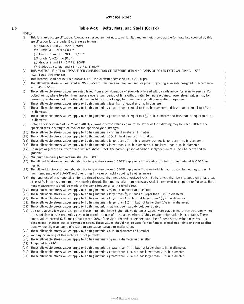
ASME B31.1-2010
(10) Table A-10 Bolts, Nuts, and Studs (Cont’d)NOTES:(1) This is a product specification. Allowable stresses are not necessary. Limitations on metal temperature for materials covered by this
specification for use under B31.1 are as follows:(a) Grades 1 and 2, −20°F to 600°F(b) Grade 2H, −20°F to 800°F(c) Grades 3 and 7, −20°F to 1,100°F(d) Grade 4, −20°F to 900°F(e) Grades 6 and 8F, −20°F to 800°F(f) Grades 8, 8C, 8M, and 8T, −20°F to 1,200°F
(2) THIS MATERIAL IS NOT ACCEPTABLE FOR CONSTRUCTION OF PRESSURE-RETAINING PARTS OF BOILER EXTERNAL PIPING — SEEFIGS. 100.1.2(A) AND (B).
(3) This material shall not be used above 400°F. The allowable stress value is 7,000 psi.(4) The allowable stress values listed in MSS SP-58 for this material may be used for pipe supporting elements designed in accordance
with MSS SP-58.(5) These allowable stress values are established from a consideration of strength only and will be satisfactory for average service. For
bolted joints, where freedom from leakage over a long period of time without retightening is required, lower stress values may benecessary as determined from the relative flexibility of the flange, bolt, and corresponding relaxation properties.
(6) These allowable stress values apply to bolting materials less than or equal to 1 in. in diameter.(7) These allowable stress values apply to bolting materials greater than or equal to 1 in. in diameter and less than or equal to 11⁄2 in.
in diameter.(8) These allowable stress values apply to bolting materials greater than or equal to 11⁄2 in. in diameter and less than or equal to 3 in.
in diameter.(9) Between temperatures of −20°F and 400°F, allowable stress values equal to the lower of the following may be used: 20% of the
specified tensile strength or 25% of the specified yield strength.(10) These allowable stress values apply to bolting materials 4 in. in diameter and smaller.(11) These allowable stress values apply to bolting materials 21⁄2 in. in diameter and smaller.(12) These allowable stress values apply to bolting materials larger than 21⁄2 in. in diameter but not larger than 4 in. in diameter.(13) These allowable stress values apply to bolting materials larger than 4 in. in diameter but not larger than 7 in. in diameter.(14) Upon prolonged exposures to temperatures above 875°F, the carbide phase of carbon–molybdenum steel may be converted to
graphite.(15) Minimum tempering temperature shall be 800°F.(16) The allowable stress values tabulated for temperatures over 1,000°F apply only if the carbon content of the material is 0.04% or
higher.(17) The allowable stress values tabulated for temperatures over 1,000°F apply only if the material is heat treated by heating to a mini-
mum temperature of 1,900°F and quenching in water or rapidly cooling by other means.(18) The hardness of this material, under the thread roots, shall not exceed Rockwell C35. The hardness shall be measured on a flat area,
at least 1⁄8 in. across, prepared by removing thread. No more material than necessary shall be removed to prepare the flat area. Hard-ness measurements shall be made at the same frequency as the tensile test.
(19) These allowable stress values apply to bolting materials 3⁄4 in. in diameter and smaller.(20) These allowable stress values apply to bolting materials larger than 3⁄4 in. but not larger than 1 in. in diameter.(21) These allowable stress values apply to bolting materials larger than 1 in. but not larger than 11⁄4 in. in diameter.(22) These allowable stress values apply to bolting materials larger than 11⁄4 in. but not larger than 11⁄2 in. in diameter.(23) These allowable stress values apply to bolting material that has been carbide solution treated.(24) Due to relatively low yield strength of these materials, these higher allowable stress values were established at temperatures where
the short-time tensile properties govern to permit the use of these alloys where slightly greater deformation is acceptable. Thesestress values exceed 67% but do not exceed 90% of the yield strength at temperature. Use of these stress values may result indimensional changes due to permanent strain. These values should not be used for the flanges of gasketed joints or other applica-tions where slight amounts of distortion can cause leakage or malfunction.
(25) These allowable stress values apply to bolting materials 8 in. in diameter and smaller.(26) Welding or brazing of this material is not permitted.(27) These allowable stress values apply to bolting materials 1⁄2 in. in diameter and smaller.(28) Tempered to HR50.(29) These allowable stress values apply to bolting materials greater than 1⁄2 in. but not larger than 1 in. in diameter.(30) These allowable stress values apply to bolting materials greater than 1 in. but not larger than 2 in. in diameter.(31) These allowable stress values apply to bolting materials greater than 2 in. but not larger than 3 in. in diameter.
204
Copyright ASME International Provided by IHS under license with ASME No reproduction or networking permitted without license from IHS
--`,,```````,,```,`,`,,,,`,`,`,`-`-`,,`,,`,`,,`---
标准分享网 www.bzfxw.com 免费下载

ASME B31.1-2010
MANDATORY APPENDIX B
Begins on next page.
205
Copyright ASME International Provided by IHS under license with ASME No reproduction or networking permitted without license from IHS
--`,,```````,,```,`,`,,,,`,`,`,`-`-`,,`,,`,`,,`---

ASME B31.1-2010
Tabl
eB
-1Th
erm
alEx
pans
ion
Dat
a
Ap
Mea
nCo
effi
cien
tof
Ther
mal
Expa
nsio
n,10
−6in
./in
./°F
�in
Goi
ngFr
om70
°Fto
Indi
cate
dTe
mpe
ratu
re[N
ote
(1)]
Bp
Line
arTh
erm
alEx
pans
ion,
in./
100
ft
Tem
pera
ture
Ran
ge70
°Fto
Coef
-M
ater
ial
fici
ent
−32
5−
150
−50
7020
030
040
050
060
070
080
090
010
0011
0012
0013
0014
00
Gro
up1
carb
onan
dlo
wal
loy
A5.
55.
96.
26.
46.
76.
97.
17.
37.
47.
67.
87.
98.
18.
28.
38.
48.
4st
eels
[Not
e(2
)]B
−2.
6−
1.6
−0.
90
1.0
1.9
2.8
3.7
4.7
5.7
6.8
7.9
9.0
10.1
11.3
12.4
14.7
Gro
up2
low
allo
yst
eels
[Not
e(3
)]A
6.0
6.5
6.7
7.0
7.3
7.4
7.6
7.7
7.8
7.9
8.1
8.1
8.2
8.3
8.4
8.4
8.5
B−
2.9
−1.
7−
1.0
01.
12.
13.
04.
05.
06.
07.
18.
19.
210
.311
.412
.414
.8
5Cr–
1Mo
stee
lsA
5.6
6.0
6.2
6.4
6.7
6.9
7.0
7.1
7.2
7.3
7.3
7.4
7.5
7.6
7.6
7.7
7.8
B−
2.7
−1.
6−
0.9
01.
11.
92.
83.
64.
65.
56.
47.
48.
49.
410
.411
.412
.4
9Cr–
1Mo
stee
lsA
5.0
5.4
5.6
5.8
6.0
6.2
6.3
6.4
6.5
6.6
6.7
6.8
6.9
7.0
7.1
7.2
7.2
B−
2.4
−1.
4−
0.8
00.
91.
72.
53.
34.
15.
05.
96.
87.
78.
79.
610
.611
.6
Str
aigh
tch
rom
ium
stai
nles
sst
eels
12Cr
to13
Crst
eels
A5.
15.
55.
75.
96.
26.
36.
46.
56.
56.
66.
76.
76.
86.
86.
96.
97.
0B
−2.
4−
1.5
−0.
80
1.0
1.7
2.5
3.3
4.2
5.0
5.8
6.7
7.6
8.4
9.3
10.2
10.6
15Cr
to17
Crst
eels
A4.
54.
95.
15.
35.
55.
75.
85.
96.
06.
16.
16.
26.
36.
46.
46.
56.
6B
−2.
1−
1.3
−0.
70
0.9
1.6
2.3
3.0
3.8
4.6
5.3
6.2
7.0
7.9
8.7
9.6
10.0
27Cr
stee
lsA
4.3
4.7
4.9
5.0
5.2
5.2
5.3
5.4
5.4
5.5
5.6
5.7
5.7
5.8
5.9
5.9
6.0
B−
2.0
−1.
2−
0.7
00.
81.
42.
12.
83.
54.
24.
95.
66.
47.
27.
98.
89.
6
Aus
teni
tic
stai
nles
sst
eels
(304
,A
7.5
8.0
8.2
8.5
8.9
9.2
9.5
9.7
9.8
10.0
10.1
10.2
10.3
10.5
10.6
10.7
10.8
305,
316,
317,
321,
347,
348
B−
3.6
−2.
1−
1.2
01.
42.
53.
75.
06.
37.
58.
810
.211
.512
.914
.315
.717
.219
-9D
L,XM
-15,
etc.
)
Oth
erau
sten
itic
stai
nles
sst
eels
A7.
17.
67.
88.
28.
58.
88.
99.
19.
29.
39.
49.
59.
69.
79.
89.
910
.1(3
09,
310,
315,
XM-1
9,et
c.)
B−
3.4
−2.
0−
1.1
01.
32.
43.
54.
75.
87.
08.
29.
510
.712
.013
.314
.716
.0
Gra
yca
stir
onA
...
...
...
...
5.8
5.9
6.1
6.3
6.5
6.7
6.8
7.0
7.2
...
...
...
...
B..
...
...
.0
0.9
1.6
2.4
3.2
4.1
5.0
6.0
7.0
8.0
...
...
...
...
Duc
tile
cast
iron
A..
.4.
95.
35.
76.
06.
36.
56.
97.
07.
17.
37.
47.
5..
...
...
...
.B
...
−1.
3−
0.8
00.
91.
72.
63.
54.
45.
46.
47.
48.
4..
...
...
...
.
206
Copyright ASME International Provided by IHS under license with ASME No reproduction or networking permitted without license from IHS
--`,,```````,,```,`,`,,,,`,`,`,`-`-`,,`,,`,`,,`---
标准分享网 www.bzfxw.com 免费下载
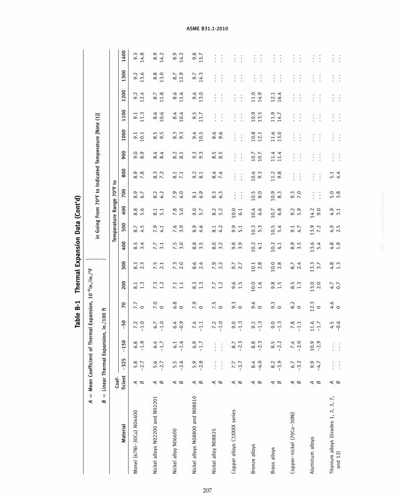
ASME B31.1-2010
Tabl
eB
-1Th
erm
alEx
pans
ion
Dat
a(C
ont‘
d)
Ap
Mea
nCo
effi
cien
tof
Ther
mal
Expa
nsio
n,10
−6in
./in
./°F
�in
Goi
ngFr
om70
°Fto
Indi
cate
dTe
mpe
ratu
re[N
ote
(1)]
Bp
Line
arTh
erm
alEx
pans
ion,
in./
100
ft
Tem
pera
ture
Ran
ge70
°Fto
Coef
-M
ater
ial
fici
ent
−32
5−
150
−50
7020
030
040
050
060
070
080
090
010
0011
0012
0013
0014
00
Mon
el(6
7Ni–
30Cu
)N
0440
0A
5.8
6.8
7.2
7.7
8.1
8.3
8.5
8.7
8.8
8.9
8.9
9.0
9.1
9.1
9.2
9.2
9.3
B−
2.7
−1.
8−
1.0
01.
32.
33.
44.
55.
66.
77.
88.
910
.111
.312
.413
.614
.8
Nic
kel
allo
ysN
0220
0an
dN
0220
1A
5.6
6.4
6.7
7.0
7.3
7.5
7.7
7.9
8.1
8.2
8.3
8.4
8.5
8.6
8.7
8.8
8.9
B−
2.7
−1.
7−
1.0
01.
22.
13.
14.
15.
16.
27.
28.
49.
510
.611
.813
.014
.2
Nic
kel
allo
yN
0660
0A
5.5
6.1
6.4
6.8
7.1
7.3
7.5
7.6
7.8
7.9
8.1
8.2
8.3
8.4
8.6
8.7
8.9
B−
2.6
−1.
6−
0.9
01.
12.
03.
03.
95.
06.
07.
18.
19.
310
.411
.612
.914
.2
Nic
kel
allo
ysN
0880
0an
dN
0881
0A
5.9
6.9
7.4
7.9
8.3
8.6
8.8
8.9
9.0
9.1
9.2
9.3
9.4
9.5
9.6
9.7
9.8
B−
2.8
−1.
7−
1.1
01.
32.
43.
54.
65.
76.
98.
19.
310
.511
.713
.014
.315
.7
Nic
kel
allo
yN
0882
5A
...
...
7.2
7.5
7.7
7.9
8.0
8.1
8.2
8.3
8.4
8.5
8.6
...
...
...
...
B..
...
.−
1.0
01.
22.
23.
24.
25.
26.
37.
48.
59.
6..
...
...
...
.
Copp
eral
loys
C1XX
XXse
ries
A7.
78.
79.
09.
39.
69.
79.
89.
910
.0..
...
...
...
...
...
...
...
.B
−3.
7−
2.3
−1.
30
1.5
2.7
3.9
5.1
6.1
...
...
...
...
...
...
...
...
Bro
nze
allo
ysA
8.4
8.8
9.2
9.6
10.0
10.1
10.2
10.3
10.4
10.5
10.6
10.7
10.8
10.9
11.0
...
...
B−
4.0
−2.
3−
1.3
01.
62.
84.
15.
36.
68.
09.
310
.712
.113
.514
.9..
...
.
Bra
ssal
loys
A8.
28.
59.
09.
39.
810
.010
.210
.510
.710
.911
.211
.411
.611
.912
.1..
...
.B
−3.
9−
2.2
−1.
30
1.5
2.8
4.1
5.4
6.8
8.3
9.8
11.4
13.0
14.7
16.4
...
...
Copp
er–
nick
el(7
0Cu–
30N
i)A
6.7
7.4
7.8
8.2
8.5
8.7
8.9
9.1
9.2
9.3
...
...
...
...
...
...
...
B−
3.2
−2.
0−
1.1
01.
32.
43.
54.
75.
97.
0..
...
...
...
...
...
...
.
Alu
min
umal
loys
A9.
910
.911
.612
.313
.013
.313
.613
.914
.2..
...
...
...
...
...
...
...
.B
−4.
7−
2.9
−1.
70
2.0
3.7
5.4
7.2
9.0
...
...
...
...
...
...
...
...
Tita
nium
allo
ys(G
rade
s1,
2,3,
7,A
...
...
4.5
4.6
4.7
4.8
4.8
4.9
4.9
5.0
5.1
...
...
...
...
...
...
and
12)
B..
...
.−
0.6
00.
71.
31.
92.
53.
13.
84.
4..
...
...
...
...
...
.
207
Copyright ASME International Provided by IHS under license with ASME No reproduction or networking permitted without license from IHS
--`,,```````,,```,`,`,,,,`,`,`,`-`-`,,`,,`,`,,`---
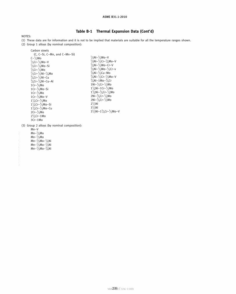
ASME B31.1-2010
Table B-1 Thermal Expansion Data (Cont’d)NOTES:(1) These data are for information and it is not to be implied that materials are suitable for all the temperature ranges shown.(2) Group 1 alloys (by nominal composition):
Carbon steels(C, C–Si, C–Mn, and C–Mn–Si)
C–1⁄2Mo1⁄2Cr–1⁄5Mo–V1⁄2Cr–1⁄4Mo–Si1⁄2Cr–1⁄2Mo1⁄2Cr–1⁄2Ni–1⁄4Mo3⁄4Cr–1⁄2Ni–Cu3⁄4Cr–3⁄4Ni–Cu–Al1Cr–1⁄5Mo1Cr–1⁄5Mo–Si1Cr–1⁄2Mo1Cr–1⁄2Mo–V11⁄4Cr–1⁄2Mo11⁄4Cr–1⁄2Mo–Si13⁄4Cr–1⁄2Mo–Cu2Cr–1⁄2Mo21⁄4Cr–1Mo3Cr–1Mo
1⁄2Ni–1⁄2Mo–V1⁄2Ni–1⁄2Cr–1⁄4Mo–V3⁄4Ni–1⁄2Mo–Cr–V3⁄4Ni–1⁄2Mo–1⁄3Cr–v3⁄4Ni–1⁄2Cu–Mo3⁄4Ni–1⁄2Cr–1⁄2Mo–V3⁄4Ni–1Mo–3⁄4Cr1Ni–1⁄2Cr–1⁄2Mo11⁄4Ni–1Cr–1⁄2Mo13⁄4Ni–3⁄4Cr–1⁄4Mo2Ni–3⁄4Cr–1⁄4Mo2Ni–3⁄4Cr–1⁄3Mo21⁄2Ni31⁄2Ni31⁄2Ni–13⁄4Cr–1⁄2Mo–V
(3) Group 2 alloys (by nominal composition):Mn–VMn–1⁄4MoMn–1⁄2MoMn–1⁄2Mo–1⁄4NiMn–1⁄2Mo–1⁄2NiMn–1⁄2Mo–3⁄4Ni
208
Copyright ASME International Provided by IHS under license with ASME No reproduction or networking permitted without license from IHS
--`,,```````,,```,`,`,,,,`,`,`,`-`-`,,`,,`,`,,`---
标准分享网 www.bzfxw.com 免费下载

ASME B31.1-2010
Table B-1 (SI) begins on the next page.
209
Copyright ASME International Provided by IHS under license with ASME No reproduction or networking permitted without license from IHS
--`,,```````,,```,`,`,,,,`,`,`,`-`-`,,`,,`,`,,`---

ASME B31.1-2010
Table B-1 (SI) Thermal Expansion Data
A p Mean Coefficient of Thermal Expansion, 10−6mm/mm/°C } in Going From 20°C to Indicated Temperature [Note (1)]B p Linear Thermal Expansion, mm/m
Temperature Range 20°C toCoef-Material ficient −200 −100 −50 20 50 75 100 125 150 175 200 225 250 275
Group 1 carbon and low alloy A 9.9 10.7 11.1 11.6 11.8 11.9 12.1 12.2 12.4 12.5 12.7 12.8 13.0 13.2steels [Note (2)] B −2.2 −1.3 −0.8 0 0.4 0.7 1.0 1.3 1.6 1.9 2.3 2.6 3.0 3.4
Group 2 low alloy steels [Note (3)] A 10.8 11.7 12.0 12.5 12.7 12.9 13.1 13.3 13.4 13.5 13.6 13.7 13.8 13.9B −2.4 −1.4 −0.8 0 0.4 0.7 1.0 1.4 1.7 2.1 2.5 2.8 3.2 3.6
5Cr–1Mo steels A 10.1 10.8 11.2 11.6 11.8 12.0 12.1 12.2 12.4 12.5 12.6 12.6 12.7 12.7B −2.2 −1.3 −0.8 0 0.4 0.7 1.0 1.3 1.6 1.9 2.3 2.6 2.9 3.3
9Cr–1Mo steels A 9.0 9.8 10.1 10.4 10.6 10.7 10.8 10.9 11.1 11.2 11.3 11.4 11.5 11.6B −2.0 −1.2 −0.7 0 0.3 0.6 0.9 1.1 1.4 1.7 2.0 2.3 2.6 3.0
Straight chromium stainless steels12Cr to 13Cr steels A 9.1 9.9 10.2 10.7 10.8 11.0 11.1 11.2 11.3 11.4 11.5 11.6 11.7 11.7
B −2.0 −1.2 −0.7 0 0.3 0.6 0.9 1.2 1.5 1.8 2.1 2.4 2.7 3.0
15Cr to 17Cr steels A 8.1 8.8 9.1 9.6 9.7 9.8 9.9 10.0 10.2 10.3 10.3 10.4 10.5 10.6B −1.8 −1.1 −0.6 0 0.3 0.5 0.8 1.1 1.3 1.6 1.9 2.1 2.4 2.7
27Cr steels A 7.7 8.5 8.7 9.0 9.1 9.2 9.3 9.4 9.4 9.5 9.5 9.6 9.7 9.7B −1.7 −1.0 −0.6 0 0.3 0.5 0.7 1.0 1.2 1.5 1.7 2.0 2.2 2.5
Austenitic stainless steels (304, A 13.5 14.3 14.7 15.3 15.6 15.9 16.1 16.4 16.6 16.8 17.0 17.2 17.3 17.5(305, 316, 317, 321, 347, 348 B −3.0 −1.7 −1.0 0 0.5 0.9 1.3 1.7 2.2 2.6 3.1 3.5 4.0 4.519-9DL XM-15, etc.)
Other austenitic stainless steels A 12.8 13.6 14.1 14.7 14.9 15.1 15.4 15.6 15.8 16.0 16.1 16.2 16.3 16.4(309, 310, 315, XM-19, etc.) B −2.8 −1.6 −1.0 0 0.4 0.8 1.2 1.6 2.1 2.5 2.9 3.3 3.8 4.2
Gray cast iron A . . . . . . . . . 9.8 10.1 10.2 10.4 10.5 10.7 10.8 11.0 11.1 11.2 11.4B . . . . . . . . . 0 0.3 0.6 0.8 1.1 1.4 1.7 2.0 2.3 2.6 2.9
Ductile cast iron A . . . 8.8 9.5 10.3 10.6 10.8 10.9 11.1 11.3 11.4 11.7 12.0 12.2 12.3B . . . −1.1 −0.7 0 0.3 0.6 0.9 1.2 1.5 1.8 2.1 2.5 2.8 3.1
Monel (67Ni–30Cu) N04400 A 10.4 12.2 13.0 13.8 14.1 14.4 14.7 14.9 15.0 15.2 15.3 15.4 15.6 15.7B −2.3 −1.5 −0.9 0 0.4 0.8 1.2 1.6 2.0 2.4 2.8 3.2 3.6 4.0
Nickel alloys N02200 and N02201 A 10.1 11.5 12.0 12.7 12.9 13.1 13.3 13.5 13.6 13.8 13.9 14.0 14.2 14.3B −2.2 −1.4 −0.8 0 0.4 0.7 1.1 1.4 1.8 2.1 2.5 2.9 3.3 3.6
Nickel alloy N06600 A 9.9 10.8 11.5 12.2 12.5 12.7 12.8 13.1 13.2 13.3 13.5 13.6 13.7 13.8B −2.2 −1.3 −0.8 0 0.4 0.7 1.0 1.4 1.7 2.1 2.4 2.8 3.2 3.5
Nickel alloys N08800 and N08810 A 10.6 12.5 13.3 14.3 14.6 14.9 15.1 15.3 15.5 15.7 15.8 15.9 16.0 16.1B −2.3 −1.5 −0.9 0 0.4 0.8 1.2 1.6 2.0 2.4 2.8 3.3 3.7 4.1
Nickel alloy N08825 A . . . . . . 12.9 13.5 13.6 13.8 13.9 14.0 14.1 14.2 14.4 14.4 14.5 14.6B . . . . . . −0.9 0 0.4 0.8 1.1 1.5 1.8 2.2 2.6 3.0 3.3 3.7
210
Copyright ASME International Provided by IHS under license with ASME No reproduction or networking permitted without license from IHS
--`,,```````,,```,`,`,,,,`,`,`,`-`-`,,`,,`,`,,`---
标准分享网 www.bzfxw.com 免费下载

ASME B31.1-2010
Table B-1 (SI) Thermal Expansion Data
A p Mean Coefficient of Thermal Expansion, 10−6mm/mm/°C } in Going From 20°C to Indicated Temperature [Note (1)]B p Linear Thermal Expansion, mm/m
Temperature Range 20°C to
300 325 350 375 400 425 450 475 500 525 550 575 600 625 650 675 700 725 750 775 800
13.3 13.5 13.6 13.7 13.8 13.9 14.1 14.2 14.3 14.4 14.6 14.7 14.8 14.9 15.0 15.0 15.1 15.1 15.2 . . . . . .3.7 4.1 4.5 4.9 5.2 5.6 6.1 6.5 6.9 7.3 7.7 8.1 8.6 9.0 9.4 9.8 10.2 10.7 11.1 . . . . . .
14.0 14.1 14.2 14.3 14.4 14.5 14.6 14.6 14.7 14.8 14.8 14.9 14.9 15.0 15.1 15.1 15.2 . . . . . . . . . . . .3.9 4.3 4.7 5.1 5.5 5.9 6.3 6.7 7.1 7.5 7.9 8.3 8.7 9.1 9.5 9.9 10.3 . . . . . . . . . . . .
12.8 12.9 13.0 13.1 13.1 13.2 13.2 13.3 13.4 13.5 13.5 13.6 13.6 13.7 13.8 13.8 13.9 . . . . . . . . . . . .3.6 3.9 4.3 4.6 5.0 5.3 5.7 6.1 6.4 6.8 7.2 7.5 7.9 8.3 8.7 9.1 9.4 . . . . . . . . . . . .
11.7 11.8 11.8 11.9 12.0 12.1 12.2 12.2 12.3 12.4 12.5 12.6 12.6 12.7 12.8 12.8 12.9 . . . . . . . . . . . .3.3 3.6 3.9 4.2 4.6 4.9 5.2 5.6 5.9 6.3 6.6 7.0 7.3 7.7 8.1 8.4 8.8 . . . . . . . . . . . .
11.7 11.8 11.8 11.9 11.9 12.0 12.1 12.1 12.2 12.2 12.2 12.3 12.3 12.4 12.4 12.4 12.5 . . . . . . . . . . . .3.3 3.6 3.9 4.2 4.5 4.9 5.2 5.5 5.8 6.2 6.5 6.8 7.2 7.5 7.8 8.1 8.5 . . . . . . . . . . . .
10.7 10.8 10.8 10.9 11.0 11.0 11.1 11.2 11.3 11.3 11.4 11.4 11.5 11.6 11.6 11.7 11.7 . . . . . . . . . . . .3.0 3.3 3.6 3.9 4.2 4.5 4.8 5.1 5.4 5.7 6.0 6.3 6.7 7.0 7.3 7.6 8.0 . . . . . . . . . . . .
9.8 9.8 9.9 9.9 10.0 10.0 10.1 10.2 10.2 10.3 10.3 10.4 10.4 10.5 10.6 10.6 10.7 . . . . . . . . . . . .2.7 3.0 3.3 3.5 3.8 4.1 4.3 4.6 4.9 5.2 5.5 5.8 6.1 6.4 6.7 7.0 7.3 . . . . . . . . . . . .
17.6 17.7 17.9 18.0 18.1 18.2 18.3 18.3 18.5 18.5 18.6 18.7 18.8 18.9 19.0 19.1 19.2 . . . . . . . . . . . .4.9 5.4 5.9 6.4 6.9 7.4 7.8 8.3 8.9 9.4 9.9 10.4 10.9 11.4 12.0 12.5 13.0 . . . . . . . . . . . .
16.5 16.5 16.7 16.7 16.8 16.9 17.0 17.1 17.2 17.2 17.3 17.4 17.5 17.6 17.7 17.8 17.9 . . . . . . . . . . . .4.6 5.0 5.5 5.9 6.4 6.8 7.3 7.8 8.2 8.7 9.2 9.7 10.1 10.6 11.1 11.6 12.2 . . . . . . . . . . . .
11.5 11.7 11.8 12.0 12.1 12.3 12.4 12.6 12.7 12.9 13.0 . . . . . . . . . . . . . . . . . . . . . . . . . . . . . .3.2 3.6 3.9 4.2 4.6 5.0 5.3 5.7 6.1 6.5 6.9 . . . . . . . . . . . . . . . . . . . . . . . . . . . . . .
12.5 12.7 12.7 12.9 13.0 13.1 13.1 13.2 13.3 13.5 13.6 . . . . . . . . . . . . . . . . . . . . . . . . . . . . . .3.5 3.9 4.2 4.6 4.9 5.3 5.7 6.0 6.4 6.8 7.2 . . . . . . . . . . . . . . . . . . . . . . . . . . . . . .
15.8 15.9 16.0 16.0 16.1 16.1 16.2 16.2 16.2 16.3 16.3 16.3 16.4 16.4 16.5 16.5 16.5 16.6 16.6 16.7 16.74.4 4.9 5.3 5.7 6.1 6.5 7.0 7.4 7.8 8.2 8.6 9.1 9.5 9.9 10.4 10.8 11.2 11.7 12.1 12.6 13.0
14.4 14.5 14.6 14.7 14.8 14.9 15.0 15.0 15.1 15.2 15.3 15.4 15.5 15.6 15.7 15.8 15.8 15.9 16.0 16.1 16.24.0 4.4 4.8 5.2 5.6 6.0 6.4 6.8 7.3 7.7 8.1 8.5 9.0 9.4 9.9 10.3 10.8 11.2 11.7 12.2 12.6
13.9 14.0 14.1 14.2 14.4 14.5 14.6 14.7 14.8 14.9 15.0 15.0 15.2 15.3 15.4 15.6 15.7 15.8 15.9 16.1 16.23.9 4.3 4.7 5.1 5.5 5.9 6.3 6.7 7.1 7.5 7.9 8.4 8.8 9.3 9.7 10.2 10.6 11.1 11.6 12.1 12.7
16.2 16.3 16.3 16.4 16.5 16.6 16.7 16.7 16.8 16.9 17.0 17.1 17.1 17.2 17.3 17.4 17.5 17.6 17.7 17.8 17.94.5 5.0 5.4 5.8 6.3 6.7 7.2 7.6 8.1 8.5 9.0 9.5 9.9 10.4 10.9 11.4 11.9 12.4 12.9 13.4 14.0
14.7 14.8 14.9 15.0 15.1 15.1 15.2 15.3 15.4 15.5 15.6 . . . . . . . . . . . . . . . . . . . . . . . . . . . . . .4.1 4.5 4.9 5.3 5.7 6.1 6.5 7.0 7.4 7.8 8.3 . . . . . . . . . . . . . . . . . . . . . . . . . . . . . .
211
Copyright ASME International Provided by IHS under license with ASME No reproduction or networking permitted without license from IHS
--`,,```````,,```,`,`,,,,`,`,`,`-`-`,,`,,`,`,,`---

ASME B31.1-2010
Table B-1 (SI) Thermal Expansion Data (Cont’d)
A p Mean Coefficient of Thermal Expansion, 10−6mm/mm/°C } in Going From 20°C to Indicated Temperature [Note (1)]B p Linear Thermal Expansion, mm/m
Temperature Range 20°C toCoef-Material ficient −200 −100 −50 20 50 75 100 125 150 175 200 225 250 275
Copper alloys C1XXXX series A 13.9 15.7 16.2 16.8 17.0 17.1 17.3 17.4 17.5 17.6 17.7 17.8 17.9 18.0B −3.1 −1.9 −1.1 0 0.5 0.9 1.4 1.8 2.3 2.7 3.2 3.7 4.1 4.6
Bronze alloys A 15.1 15.8 16.4 17.2 17.6 17.9 18.1 18.2 18.3 18.3 18.4 18.5 18.5 18.6B −3.3 −1.9 −1.1 0 0.5 1.0 1.4 1.9 2.4 2.8 3.3 3.8 4.3 4.8
Brass alloys A 14.7 15.4 16.0 16.8 17.2 17.4 17.6 17.8 18.0 18.2 18.4 18.6 18.8 19.0B −3.2 −1.9 −1.1 0 0.5 1.0 1.4 1.9 2.3 2.8 3.3 3.8 4.3 4.8
Copper–nickel (70Cu–30Ni) A 11.9 13.4 14.0 14.7 14.9 15.2 15.4 15.5 15.7 15.9 16.1 16.2 16.3 16.4B −2.6 −1.6 −1.0 0 0.4 0.8 1.2 1.6 2.0 2.5 2.9 3.3 3.7 4.2
Aluminum alloys A 18.0 19.7 20.8 22.1 22.6 23.0 23.4 23.7 23.9 24.2 24.5 24.7 24.9 25.2B −4.0 −2.4 −1.5 0 0.7 1.3 1.9 2.5 3.1 3.7 4.4 5.1 5.7 6.4
Titanium alloys (Grades 1, 2, 3, 7, A . . . . . . 8.2 8.3 8.4 8.4 8.5 8.5 8.6 8.6 8.6 8.7 8.7 8.8and 12) B . . . . . . −0.6 0 0.3 0.5 0.7 0.9 1.1 1.3 1.6 1.8 2.0 2.2
NOTES:(1) These data are for information and it is not to be implied that materials are suitable for all the temperature ranges shown.(2) Group 1 alloys (by nominal composition):
Carbon steels(C, C–Si, C–Mn, and C–Mn–Si)
C–1⁄2Mo1⁄2Cr–1⁄5Mo–V1⁄2Cr–1⁄4Mo–Si1⁄2Cr–1⁄2Mo1⁄2Cr–1⁄2Ni–1⁄4Mo3⁄4Cr–1⁄2Ni–Cu3⁄4Cr–3⁄4Ni–Cu–Al1Cr–1⁄5Mo1Cr–1⁄5Mo–Si1Cr–1⁄2Mo1Cr–1⁄2Mo–V11⁄4Cr–1⁄2Mo11⁄4Cr–1⁄2Mo–Si13⁄4Cr–1⁄2Mo–Cu2Cr–1⁄2Mo21⁄4Cr–1Mo3Cr–1Mo
1⁄2Ni–1⁄2Mo–V1⁄2Ni–1⁄2Cr–1⁄4Mo–V3⁄4Ni–1⁄2Mo–Cr–V3⁄4Ni–1⁄2Mo–1⁄3Cr–V3⁄4Ni–1⁄2Cu–Mo3⁄4Ni–1⁄2Cr–1⁄2Mo–V3⁄4Ni–1Mo–3⁄4Cr1Ni–1⁄2Cr–1⁄2Mo11⁄4Ni–1Cr–1⁄2Mo13⁄4Ni–3⁄4Cr–1⁄4Mo2Ni–3⁄4Cr–1⁄4Mo2Ni–3⁄4Cr–1⁄3Mo21⁄2Ni31⁄2Ni31⁄2Ni–13⁄4Cr–1⁄2Mo–V
(3) Group 2 alloys (by nominal composition):
Mn–VMn–1⁄4MoMn–1⁄2MoMn–1⁄2Mo–1⁄4NiMn–1⁄2Mo–1⁄2NiMn–1⁄2Mo–3⁄4Ni
212
Copyright ASME International Provided by IHS under license with ASME No reproduction or networking permitted without license from IHS
--`,,```````,,```,`,`,,,,`,`,`,`-`-`,,`,,`,`,,`---
标准分享网 www.bzfxw.com 免费下载
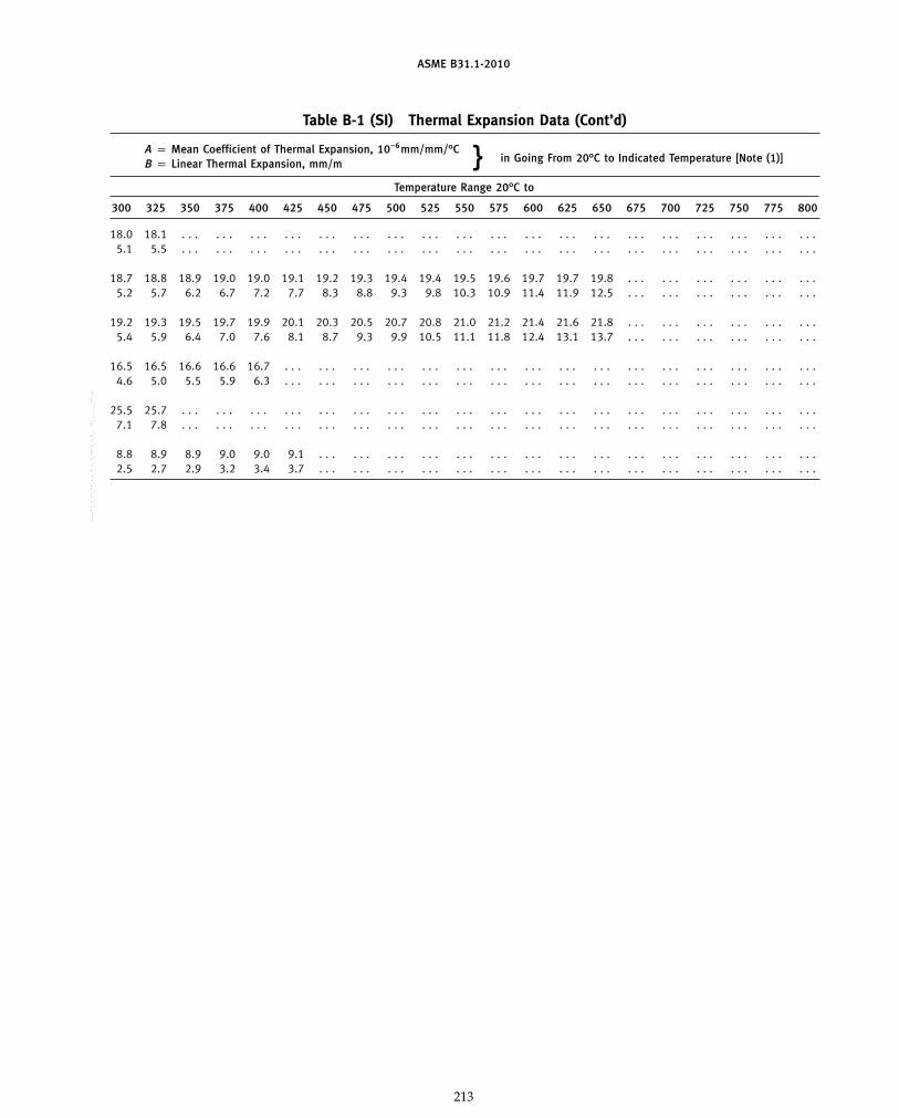
ASME B31.1-2010
Table B-1 (SI) Thermal Expansion Data (Cont’d)
A p Mean Coefficient of Thermal Expansion, 10−6mm/mm/°C } in Going From 20°C to Indicated Temperature [Note (1)]B p Linear Thermal Expansion, mm/m
Temperature Range 20°C to
300 325 350 375 400 425 450 475 500 525 550 575 600 625 650 675 700 725 750 775 800
18.0 18.1 . . . . . . . . . . . . . . . . . . . . . . . . . . . . . . . . . . . . . . . . . . . . . . . . . . . . . . . . .5.1 5.5 . . . . . . . . . . . . . . . . . . . . . . . . . . . . . . . . . . . . . . . . . . . . . . . . . . . . . . . . .
18.7 18.8 18.9 19.0 19.0 19.1 19.2 19.3 19.4 19.4 19.5 19.6 19.7 19.7 19.8 . . . . . . . . . . . . . . . . . .5.2 5.7 6.2 6.7 7.2 7.7 8.3 8.8 9.3 9.8 10.3 10.9 11.4 11.9 12.5 . . . . . . . . . . . . . . . . . .
19.2 19.3 19.5 19.7 19.9 20.1 20.3 20.5 20.7 20.8 21.0 21.2 21.4 21.6 21.8 . . . . . . . . . . . . . . . . . .5.4 5.9 6.4 7.0 7.6 8.1 8.7 9.3 9.9 10.5 11.1 11.8 12.4 13.1 13.7 . . . . . . . . . . . . . . . . . .
16.5 16.5 16.6 16.6 16.7 . . . . . . . . . . . . . . . . . . . . . . . . . . . . . . . . . . . . . . . . . . . . . . . .4.6 5.0 5.5 5.9 6.3 . . . . . . . . . . . . . . . . . . . . . . . . . . . . . . . . . . . . . . . . . . . . . . . .
25.5 25.7 . . . . . . . . . . . . . . . . . . . . . . . . . . . . . . . . . . . . . . . . . . . . . . . . . . . . . . . . .7.1 7.8 . . . . . . . . . . . . . . . . . . . . . . . . . . . . . . . . . . . . . . . . . . . . . . . . . . . . . . . . .
8.8 8.9 8.9 9.0 9.0 9.1 . . . . . . . . . . . . . . . . . . . . . . . . . . . . . . . . . . . . . . . . . . . . .2.5 2.7 2.9 3.2 3.4 3.7 . . . . . . . . . . . . . . . . . . . . . . . . . . . . . . . . . . . . . . . . . . . . .
213
Copyright ASME International Provided by IHS under license with ASME No reproduction or networking permitted without license from IHS
--`,,```````,,```,`,`,,,,`,`,`,`-`-`,,`,,`,`,,`---

ASME B31.1-2010
MANDATORY APPENDIX C
Table C-1 Moduli of Elasticity for Ferrous Material
E p Modulus of Elasticity, psi (Multiply Tabulated Values by 106) [Note (1)]
Temperature, °F
Material −100 70 200 300 400 500 600 700 800 900 1000 1100 1200 1300 1400 1500
Carbon steels with carbon content 30.2 29.5 28.8 28.3 27.7 27.3 26.7 25.5 24.2 22.4 20.4 18.0 . . . . . . . . . . . .0.30% or less
Carbon steels with carbon content 30.0 29.3 28.6 28.1 27.5 27.1 26.5 25.3 24.0 22.3 20.2 17.9 15.4 . . . . . . . . .above 0.30%
Carbon–molybdenum steels 29.9 29.2 28.5 28.0 27.4 27.0 26.4 25.3 23.9 22.2 20.1 17.8 15.3 . . . . . . . . .
Nickel steels 28.5 27.8 27.1 26.7 26.1 25.7 25.2 24.6 23.9 23.2 22.4 21.5 20.4 19.2 17.7 . . .
Chromium steels:1⁄2Cr through 2Cr 30.4 29.7 29.0 28.5 27.9 27.5 26.9 26.3 25.5 24.8 23.9 23.0 21.8 20.5 18.9 . . .21⁄4Cr through 3Cr 31.4 30.6 29.8 29.4 28.8 28.3 27.7 27.1 26.3 25.6 24.6 23.7 22.5 21.1 19.4 . . .5Cr through 9Cr 31.7 30.9 30.1 29.7 29.0 28.6 28.0 27.3 26.1 24.7 22.7 20.4 18.2 15.5 12.7 . . .
Austenitic stainless steels:Type 304, 18Cr–8NiType 310, 25Cr–20NiType 316, 16Cr–12Ni–2Mo
29.1 28.3 27.6 27.0 26.5 25.8 25.3 24.8 24.1 23.5 22.8 22.1 21.2 20.2 19.2 18.1Type 321, 18Cr–10Ni–TiType 347, 18Cr–10Ni–CbType 309, 23Cr–12Ni
Straight chromium stainless steels(12Cr, 17Cr, 27Cr) 30.1 29.2 28.5 27.9 27.3 26.7 26.1 25.6 24.7 23.2 21.5 19.1 16.6 . . . . . . . . .
Gray cast iron . . . 13.4 13.2 12.9 12.6 12.2 11.7 11.0 10.2 . . . . . . . . . . . . . . . . . . . . .
NOTE:(1) These data are for information and it is not to be implied that materials are suitable for all the temperature ranges shown.
214
Copyright ASME International Provided by IHS under license with ASME No reproduction or networking permitted without license from IHS
--`,,```````,,```,`,`,,,,`,`,`,`-`-`,,`,,`,`,,`---
标准分享网 www.bzfxw.com 免费下载

ASME B31.1-2010
Table C-1 (SI) Moduli of Elasticity for Ferrous Material
E p Modulus of Elasticity, MPa (Multiply Tabulated Values by 103) [Note (1)]
Temperature, °C
Material −75 20 50 100 150 200 250 300 350 400 450 500 550 600 650 700 750 800
Carbon steels with carbon content 208 203 201 198 195 191 189 185 179 172 162 150 136 122 107 . . . . . . . . .0.30% or less
Carbon steels with carbon content 207 202 200 197 194 190 188 184 178 171 161 149 135 121 106 . . . . . . . . .above 0.30%
Carbon–molybdenum steels 206 201 199 196 193 189 187 183 177 170 160 149 135 121 106 . . . . . . . . .
Nickel steels 196 192 190 187 184 180 178 174 169 162 153 141 128 115 101 . . . . . . . . .
Chromium steels:1⁄2Cr through 2Cr 210 205 204 201 197 193 190 186 181 176 170 160 148 133 . . . . . . . . . . . .21⁄4Cr through 3Cr 216 211 210 207 203 199 195 191 187 182 175 165 153 137 . . . . . . . . . . . .5Cr through 9Cr 219 213 212 209 205 201 197 193 189 185 181 176 171 164 156 147 138 . . .
Austenitic stainless steels:Type 304, 18Cr–8NiType 310, 25Cr–20NiType 316, 16Cr–12Ni–2Mo
201 195 194 192 188 184 180 176 172 168 164 160 156 152 146 140 134 127Type 321, 18Cr–10Ni–TiType 347, 18Cr–10Ni–CbType 309. 23Cr–12Ni
Straight chromium stainless steels(12Cr, 17Cr, 27Cr) 208 201 200 198 194 190 186 181 178 174 167 156 144 130 113 . . . . . . . . .
Gray cast iron . . . 92 92 91 89 87 85 82 78 73 67 . . . . . . . . . . . . . . . . . . . . .
NOTE:(1) These data are for information and it is not to be implied that materials are suitable for all the temperature ranges shown.
215
Copyright ASME International Provided by IHS under license with ASME No reproduction or networking permitted without license from IHS
--`,,```````,,```,`,`,,,,`,`,`,`-`-`,,`,,`,`,,`---

ASME B31.1-2010
Table C-2 Moduli of Elasticity for Nonferrous Material
E p Modulus of Elasticity, psi (Multiply Tabulated Values by 106) [Note (1)]
Temperature, °F
Materials −100 70 200 300 400 500 600 700 800 900 1,000 1,100 1,200
High Nickel Alloys
N02200 (200)N02201 (201) 30.9 30.0 29.3 28.8 28.5 28.1 27.8 27.3 26.7 26.1 25.5 25.1 24.5
N04400 (400) 26.8 26.0 25.4 25.0 24.7 24.3 24.1 23.7 23.1 22.6 22.1 21.7 21.2
N06002 (X) 29.4 28.5 27.8 27.4 27.1 26.6 26.4 25.9 25.4 24.8 24.2 23.7 23.2N06600 (600) 31.9 31.0 30.2 29.9 29.5 29.0 28.7 28.2 27.6 27.0 26.4 25.9 25.3N06617 (617) . . . 29.2 28.4 28.0 27.7 27.4 27.0 26.5 26.0 25.5 24.9 24.3 23.8N06625 (625) 30.9 30.0 29.3 28.8 28.5 28.1 27.8 27.3 26.7 26.1 25.5 25.1 24.5
N08800 (800) (2)N08810 (800H) (2) 29.4 28.5 27.8 27.4 27.1 26.6 26.4 25.9 25.4 24.8 24.2 23.8 23.2
N10001 (B) 32.0 31.1 30.3 29.9 29.5 29.1 28.8 28.3 27.7 27.1 26.4 26.0 25.3
N06007 (G) 28.6 27.8 27.1 26.7 26.4 26.0 25.7 25.3 24.7 24.2 23.6 23.2 22.7N06455 (C-4) 30.6 29.8 29.1 28.6 28.3 27.9 27.6 27.1 26.5 25.9 25.3 24.9 24.3N08320 (20 Mod) 28.6 27.8 27.1 26.7 26.4 26.0 25.7 25.3 24.7 24.2 23.6 23.2 22.7N10276 (C-276) 30.6 29.8 29.1 28.6 28.3 27.9 27.6 27.1 26.5 25.9 25.3 24.9 24.3N10665 (B-2) 32.3 31.4 30.6 30.1 29.8 29.3 29.0 28.6 27.9 27.3 26.7 26.2 25.6
Aluminum and Aluminum Alloys
A24430 (B443)A91060 (1060)A91100 (1100)A93003 (3003) 10.5 10.0 9.6 9.2 8.7 8.1 . . . . . . . . . . . . . . . . . . . . .A93004 (3004)A96061 (6061)A96063 (6063)
A95052 (5052)A95154 (5154)
10.7 10.2 9.7 9.4 8.9 8.3 . . . . . . . . . . . . . . . . . . . . .A95454 (5454)A95652 (5652)
A03560 (356)A95083 (5083)
10.8 10.3 9.8 9.5 9.0 8.3 . . . . . . . . . . . . . . . . . . . . .A95086 (5086)A95456 (5456)
Copper and Copper Alloys
C83600C92200 14.4 14.0 13.7 13.4 13.2 12.9 12.5 12.0 . . . . . . . . . . . . . . .
C46400C65500
15.4 15.0 14.6 14.4 14.1 13.8 13.4 12.8 . . . . . . . . . . . . . . .C95200C95400
C11000 16.5 16.0 15.6 15.4 15.0 14.7 14.2 13.7 . . . . . . . . . . . . . . .
216
Copyright ASME International Provided by IHS under license with ASME No reproduction or networking permitted without license from IHS
--`,,```````,,```,`,`,,,,`,`,`,`-`-`,,`,,`,`,,`---
标准分享网 www.bzfxw.com 免费下载

ASME B31.1-2010
Table C-2 Moduli of Elasticity for Nonferrous Material (Cont’d)
E p Modulus of Elasticity, psi (Multiply Tabulated Values by 106) [Note (1)]
Temperature, °F
Materials −100 70 200 300 400 500 600 700 800 900 1,000 1,100 1,200
Copper and Copper Alloys (Cont’d)
C10200C12000C12200C12500 17.5 17.0 16.6 16.3 16.0 15.6 15.1 14.5 . . . . . . . . . . . . . . .C14200C23000C61400
C70600 18.5 18.0 17.6 17.3 16.9 16.6 16.0 15.4 . . . . . . . . . . . . . . .C97600 19.6 19.0 18.5 18.2 17.9 17.5 16.9 16.2 . . . . . . . . . . . . . . .C71000 20.6 20.0 19.5 19.2 18.8 18.4 17.8 17.1 . . . . . . . . . . . . . . .C71500 22.7 22.0 21.5 21.1 20.7 20.2 19.6 18.8 . . . . . . . . . . . . . . .
Unalloyed Titanium
Grades 1, 2, 3,. . . 15.5 15.0 14.6 14.0 13.3 12.6 11.9 11.2 . . . . . . . . . . . .
7, and 12
NOTES:(1) These data are for information and it is not to be implied that materials are suitable for all the temperature ranges shown.(2) For N08800 and N08810, use the following E values above 1,200°F: at 1,300°F, E p 22.7; at 1,400°F, E p 21.9; at 1,500°F,
E p 21.2 � 106 psi.
217
Copyright ASME International Provided by IHS under license with ASME No reproduction or networking permitted without license from IHS
--`,,```````,,```,`,`,,,,`,`,`,`-`-`,,`,,`,`,,`---
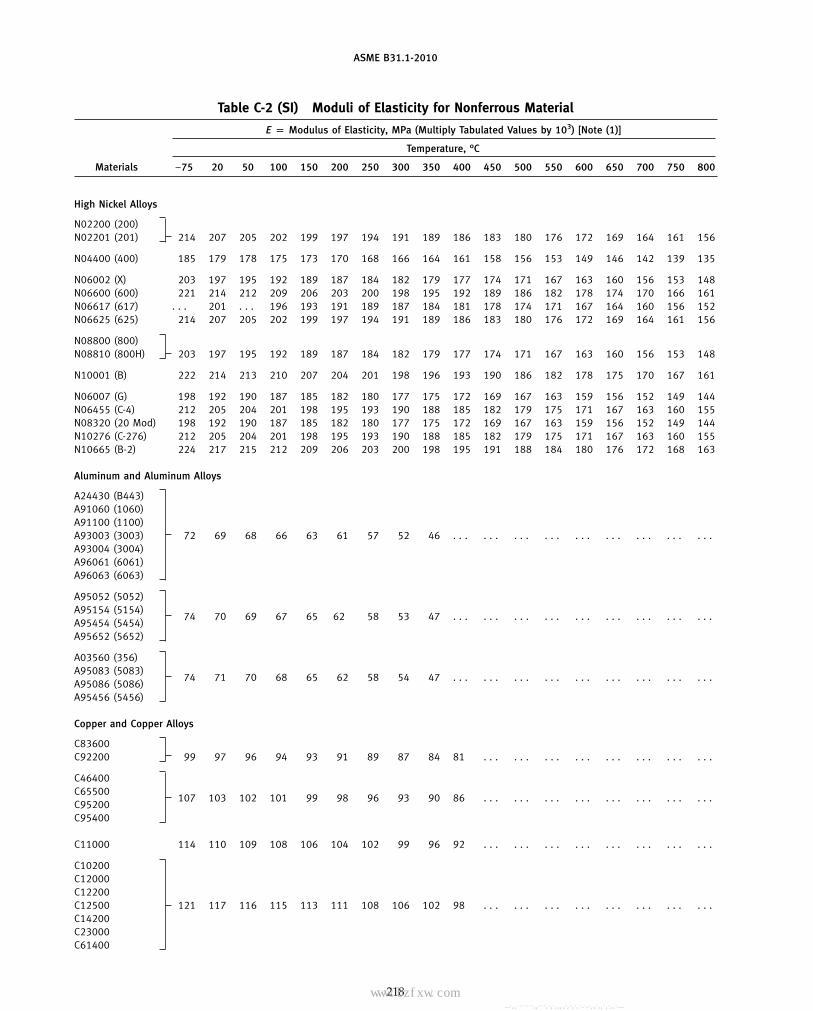
ASME B31.1-2010
Table C-2 (SI) Moduli of Elasticity for Nonferrous Material
E p Modulus of Elasticity, MPa (Multiply Tabulated Values by 103) [Note (1)]
Temperature, °C
Materials −75 20 50 100 150 200 250 300 350 400 450 500 550 600 650 700 750 800
High Nickel Alloys
N02200 (200)N02201 (201) 214 207 205 202 199 197 194 191 189 186 183 180 176 172 169 164 161 156
N04400 (400) 185 179 178 175 173 170 168 166 164 161 158 156 153 149 146 142 139 135
N06002 (X) 203 197 195 192 189 187 184 182 179 177 174 171 167 163 160 156 153 148N06600 (600) 221 214 212 209 206 203 200 198 195 192 189 186 182 178 174 170 166 161N06617 (617) . . . 201 . . . 196 193 191 189 187 184 181 178 174 171 167 164 160 156 152N06625 (625) 214 207 205 202 199 197 194 191 189 186 183 180 176 172 169 164 161 156
N08800 (800)N08810 (800H) 203 197 195 192 189 187 184 182 179 177 174 171 167 163 160 156 153 148
N10001 (B) 222 214 213 210 207 204 201 198 196 193 190 186 182 178 175 170 167 161
N06007 (G) 198 192 190 187 185 182 180 177 175 172 169 167 163 159 156 152 149 144N06455 (C-4) 212 205 204 201 198 195 193 190 188 185 182 179 175 171 167 163 160 155N08320 (20 Mod) 198 192 190 187 185 182 180 177 175 172 169 167 163 159 156 152 149 144N10276 (C-276) 212 205 204 201 198 195 193 190 188 185 182 179 175 171 167 163 160 155N10665 (B-2) 224 217 215 212 209 206 203 200 198 195 191 188 184 180 176 172 168 163
Aluminum and Aluminum Alloys
A24430 (B443)A91060 (1060)A91100 (1100)A93003 (3003) 72 69 68 66 63 61 57 52 46 . . . . . . . . . . . . . . . . . . . . . . . . . . .A93004 (3004)A96061 (6061)A96063 (6063)
A95052 (5052)A95154 (5154)
74 70 69 67 65 62 58 53 47 . . . . . . . . . . . . . . . . . . . . . . . . . . .A95454 (5454)A95652 (5652)
A03560 (356)A95083 (5083)
74 71 70 68 65 62 58 54 47 . . . . . . . . . . . . . . . . . . . . . . . . . . .A95086 (5086)A95456 (5456)
Copper and Copper Alloys
C83600C92200 99 97 96 94 93 91 89 87 84 81 . . . . . . . . . . . . . . . . . . . . . . . .
C46400C65500
107 103 102 101 99 98 96 93 90 86 . . . . . . . . . . . . . . . . . . . . . . . .C95200C95400
C11000 114 110 109 108 106 104 102 99 96 92 . . . . . . . . . . . . . . . . . . . . . . . .
C10200C12000C12200C12500 121 117 116 115 113 111 108 106 102 98 . . . . . . . . . . . . . . . . . . . . . . . .C14200C23000C61400
218
Copyright ASME International Provided by IHS under license with ASME No reproduction or networking permitted without license from IHS
--`,,```````,,```,`,`,,,,`,`,`,`-`-`,,`,,`,`,,`---
标准分享网 www.bzfxw.com 免费下载

ASME B31.1-2010
Table C-2 (SI) Moduli of Elasticity for Nonferrous Material (Cont’d)
E p Modulus of Elasticity, MPa (Multiply Tabulated Values by 103) [Note (1)]
Temperature, °C
Materials −75 20 50 100 150 200 250 300 350 400 450 500 550 600 650 700 750 800
Copper and Copper Alloys (Cont’d)
C70600C97600
128 124 123 121 119 117 115 112 108 104 . . . . . . . . . . . . . . . . . . . . . . . .C71000C71500
Unalloyed Titanium
Grades 1, 2, 3,. . . 107 106 103 100 97 92 88 84 79 75 71 . . . . . . . . . . . . . . . . . .
7, and 12
NOTE:(1) These data are for information and it is not to be implied that materials are suitable for all the temperature ranges shown.
219
Copyright ASME International Provided by IHS under license with ASME No reproduction or networking permitted without license from IHS
--`,,```````,,```,`,`,,,,`,`,`,`-`-`,,`,,`,`,,`---

ASME B31.1-2010
MANDATORY APPENDIX D
Table D-1 Flexibility and Stress Intensification Factors
Flexibility Flexibility StressCharacteristic, Factor, Intensification Factor,
Description h k i Sketch
Welding elbow or pipe bend 1.65h
0.9
h 2⁄3
tnR
r 2[Notes (1), (2), (3), (4), (5)]
tn
R
r
Closely spaced miter bend[Notes (1), (2), (3), (5)]s < r (1 + tan �) 1.52
h 5⁄6
0.9
h 2⁄3
stn cot �
2r 2B ≥ 6 tn
� ≤ 221⁄2 deg
tn
r
BR = s cot
2
s
θ
θ
Widely spaced miter bend[Notes (1), (2), (5), (6)] 1.52
h 5⁄6
0.9
h 2⁄3
tn (1 + cot �)
2rs ≥ r(1 + tan �)� ≤ 221⁄2 deg
tn
r
θ
θ
s
R = r (1 + cot )2
Welding tee perASME B16.9 [Notes (1), 1 0.9
h 2⁄3
3.1tn
r(2), (7)]tn
r
rx
Tc
Reinforced fabricated tee1 0.9
h 2⁄3[Notes (1), (2), (8), (9)] �tn +tr
2�5⁄2
r (tn) 3⁄2
tn
tr
SaddlePad
r
tr
Unreinforced fabricated tee1 0.9
h 2⁄3
tn
r[Notes (1), (2), (9)]tn
r
220
Copyright ASME International Provided by IHS under license with ASME No reproduction or networking permitted without license from IHS
--`,,```````,,```,`,`,,,,`,`,`,`-`-`,,`,,`,`,,`---
标准分享网 www.bzfxw.com 免费下载

ASME B31.1-2010
Table D-1 Flexibility and Stress Intensification Factors (Cont’d)
Flexibility Flexibility StressCharacteristic, Factor, Intensification Factor,
Description h k i Sketch
Branch welded-on fitting(integrally reinforced) per 1 0.9
h 2⁄3
3.3tn
rMSS SP-97 [Notes (1), (2)]
r
tn
Extruded outlet meeting therequirements of para. 1 0.9
h 2⁄3
tn
r104.3.1(G) [Notes (1), (2)]r
tn
Welded-in contour insert1 0.9
h 2⁄33.1
tn
r[Notes (1), (2), (7)] r
tn
Tc
rx
FlexibilityFactor, Stress Intensification Factor,
Description k i Sketch
For checking branch end
Branch connection1 See Fig. D-11.5 �Rm
tnh�
2⁄3
�r ′mRm
�1⁄2
�tnb
tnh� �r ′m
rp�[Notes (1), (10)]
Butt weld [Note (1)]
t ≥ 0.237 in., 1 1.0 [Note (11)]�max ≤ 1⁄16 in.,and �avg/t ≤ 0.13
Butt weld [Note (1)]
t ≥ 0.237 in., 1�max ≤ 1⁄8 in.,and �avg/t p any value
Butt weld [Note (1)]
1.9 max. or [0.9 + 2.7(�avg/t)],
t < 0.237 in., 1
but not less than 1.0
�max ≤ 1⁄16 in.,
[Note (11)]
and �avg/t ≤ 0.33
t t
δ
See Figs. 127.4.4(A), 127.4.4(B), andFillet welds 1 1.3 [Note (12)]
127.4.4(C)
1.9 max. orTapered transition per para.127.4.2(B) and 1ASME B16.25 [Note (1)] 1.3 + 0.0036
Do
tn+ 3.6
�
tn
tn
Do δ
221
Copyright ASME International Provided by IHS under license with ASME No reproduction or networking permitted without license from IHS
--`,,```````,,```,`,`,,,,`,`,`,`-`-`,,`,,`,`,,`---

ASME B31.1-2010
Table D-1 Flexibility and Stress Intensification Factors (Cont’d)
Flexibility Stress Intensification Factor,Description Factor, k i Sketch
2.0 max. or
Concentric reducer per1
ASME B16.9 [Note (13)]0.5 + 0.01� �D2
t2 �1⁄2
D1D2
t1
t2α
Threaded pipe joint or1 2.3 . . .
threaded flange
Corrugated straight pipe, orcorrugated or creased bend 5 2.5 . . .[Note (14)]
NOTES:(1) The following nomenclature applies to Table D-1:
B p length of miter segment at crotch, in. (mm)Do p outside diameter, in. (mm)
Dob p outside diameter of branch, in. (mm)R p bend radius of elbow or pipe bend, in. (mm)r p mean radius of pipe, in. (mm) (matching pipe for tees)
rx p external crotch radius of welded-in contour inserts and welding tees, in. (mm)s p miter spacing at centerline, in. (mm)
Tc p crotch thickness of welded-in contour inserts and welding tees, in. (mm)tn p nominal wall thickness of pipe, in. (mm) (matching pipe for tees)tr p reinforcement pad or saddle thickness, in. (mm)� p reducer cone angle, deg� p mismatch, in. (mm)� p one-half angle between adjacent miter axes, deg
(2) The flexibility factors k and stress intensification factors i in Table D-1 apply to bending in any plane for fittings and shall in no casebe taken less than unity. Both factors apply over the effective arc length (shown by heavy centerlines in the sketches) for curved andmiter elbows, and to the intersection point for tees. The values of k and i can be read directly from Chart D-1 by entering with thecharacteristic h computed from the formulas given.
(3) Where flanges are attached to one or both ends, the values of k and i in Table D-1 shall be multiplied by the factor c given below,which can be read directly from Chart D-2, entering with the computed h: one end flanged, c p h1/6; both ends flanged, c p h1/3.
(4) The designer is cautioned that cast butt welding elbows may have considerably heavier walls than those of the pipe with which theyare used. Large errors may be introduced unless the effect of these greater thicknesses is considered.
(5) In large diameter thin-wall elbows and bends, pressure can significantly affect magnitudes of k and i. Values from the Table may becorrected by dividing k by
�1 + 6 �PEc� �r
tn�
7/3
�Rr �1/3�
and dividing i by
�1 + 3.25 �PEc� �r
tn�
5/2
�Rr �2/3�
(6) Also includes single miter joints.(7) If rx ≥ Dob/8 and Tc ≥ 1.5tn, a flexibility characteristic, h, of 4.4tn/r may be used.(8) When tr > 1.5tn, h p 4.05tn /r.(9) The stress intensification factors in the Table were obtained from tests on full size outlet connections. For less than full size outlets,
the full size values should be used until more applicable values are developed.
222
Copyright ASME International Provided by IHS under license with ASME No reproduction or networking permitted without license from IHS
--`,,```````,,```,`,`,,,,`,`,`,`-`-`,,`,,`,`,,`---
标准分享网 www.bzfxw.com 免费下载
ASME B31.1-2010
Table D-1 Flexibility and Stress Intensification Factors (Cont’d)NOTES (Cont’d):(10) The equation applies only if the following conditions are met:
(a) The reinforcement area requirements of para. 104.3 are met.(b) The axis of the branch pipe is normal to the surface of run pipe wall.(c) For branch connections in a pipe, the arc distance measured between the centers of adjacent branches along the surface of the
run pipe is not less than three times the sum of their inside radii in the longitudinal direction or is not less than two times the sumof their radii along the circumference of the run pipe.
(d) The inside corner radius r1 (see Fig. D-1) is between 10% and 50% of tnh.(e) The outer radius r2 (see Fig. D-1) is not less than the larger of Tb /2, (Tb + y)/2 [shown in Fig. D-1 sketch (c)], or tnh /2.(f ) The outer radius r3 (see Fig. D-1) is not less than the larger of:
(1) 0.002�do;(2) 2(sin �)3 times the offset for the configurations shown in Fig. D-1 sketches (a) and (b).
(g) Rm /tnh ≤ 50 and r ′m /Rm ≤ 0.5.
(11) The stress intensification factors apply to girth butt welds between two items for which the wall thicknesses are between 0.875t and1.10t for an axial distance of �Dot. Do and t are nominal outside diameter and nominal wall thickness, respectively. �avg is the aver-age mismatch or offset.
(12) For welds to socket welded fittings, the stress intensification factor is based on the assumption that the pipe and fitting are matchedin accordance with ASME B16.11 and a full weld is made between the pipe and fitting as shown in Fig. 127.4.4(C). For welds tosocket welding flanges, the stress intensification factor is based on the weld geometry shown in Fig. 127.4.4(B) and has been shownto envelop the results of the pipe to socket welded fitting tests. Blending the toe of the fillet weld, with no undercut, smoothly intothe pipe wall, as shown in the concave fillet welds in Fig. 127.4.4(A) sketches (b) and (d), has been shown to improve the fatigueperformance of the weld.
(13) The equation applies only if the following conditions are met:(a) Cone angle � does not exceed 60 deg, and the reducer is concentric.(b) The larger of D1/t1 and D2/t2 does not exceed 100.(c) The wall thickness is not less than t1 throughout the body of the reducer, except in and immediately adjacent to the cylindrical
portion on the small end, where the thickness shall not be less than t2.(14) Factors shown apply to bending; flexibility factor for torsion equals 0.9.
223
Copyright ASME International Provided by IHS under license with ASME No reproduction or networking permitted without license from IHS
--`,,```````,,```,`,`,,,,`,`,`,`-`-`,,`,,`,`,,`---

ASME B31.1-2010
Chart D-1 Flexibility Factor, k, and Stress Intensification Factor, i
100
70
60
50
40
30
25Flexibility factor for elbows
k = 1.65/h
Flexibility factor for mitersk = 1.52/h5/6
Stress intensification factori = 0.9/h2/3
15
Str
ess
Inte
nsifi
catio
n Fa
ctor
, i, a
nd F
lexi
bilit
y Fa
ctor
, k
10987
6
5
4
3
2
10.01 0.03 0.04 0.05 0.06 0.08 0.10 0.14 0.2 0.3
Characteristic, h0.4 0.5 0.6 0.8 1.0 1.4 2.0
20
224
Copyright ASME International Provided by IHS under license with ASME No reproduction or networking permitted without license from IHS
--`,,```````,,```,`,`,,,,`,`,`,`-`-`,,`,,`,`,,`---
标准分享网 www.bzfxw.com 免费下载

ASME B31.1-2010
Chart D-2 Correction Factor, c
1.000.90
0.80
0.70
0.60
Cor
rect
ion
Fact
or, c
0.50
0.30
0.01 0.03 0.04 0.05 0.06 0.08 0.10 0.14 0.20
Characteristic, h
0.30 0.40 0.50 0.60 0.80 1.00.25
Both ends flanged c = h1/3
One end flanged c = h1/6
225
Copyright ASME International Provided by IHS under license with ASME No reproduction or networking permitted without license from IHS
--`,,```````,,```,`,`,,,,`,`,`,`-`-`,,`,,`,`,,`---
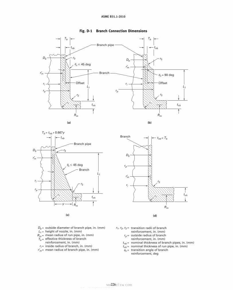
ASME B31.1-2010
Fig. D-1 Branch Connection Dimensions
Tb
r3
L1
r2
ri
Db
tnb
n � 45 deg
�
tnh
Rm
r ’m
r ’m
r ’m
r ’m
rp
Offset
Branch pipe
Branch
(a) (b)
Branch
Branch pipe
r3
r2
y
L1
ri
Db
tnb
n � 45 deg
tnh
Rm
rp
(c)
Tb
r3
L1
r2
ri
Db
tnb
n = 90 deg
tnh
Rm
rp
Offset
(d)
r2
Db
tnb = Tb
Tb = tnb + 0.667y
tnh
Rm
rp
Branch
outside diameter of branch pipe, in. (mm)height of nozzle, in. (mm)mean radius of run pipe, in. (mm)effective thickness of branchreinforcement, in. (mm)inside radius of branch, in. (mm)mean radius of branch pipe, in. (mm)
transition radii of branchreinforcement, in. (mm)outside radius of branchreinforcement, in. (mm)nominal thickness of branch pipes, in. (mm)nominal thickness of run pipe, in. (mm)transition angle of branchreinforcement, deg
Db = r1, r2, r3 =
rp =
tnb =tnh =
n =
L1 =Rm =Tb =
ri =r'm =
r1 r1
r1r1
ri
�
�
�
226
Copyright ASME International Provided by IHS under license with ASME No reproduction or networking permitted without license from IHS
--`,,```````,,```,`,`,,,,`,`,`,`-`-`,,`,,`,`,,`---
标准分享网 www.bzfxw.com 免费下载

ASME B31.1-2010
MANDATORY APPENDIX FREFERENCED STANDARDS
(10)
Specific editions of standards incorporated in this Code by reference are shown in this issue of Appendix F. It is not practical to refer toa specific edition of each standard throughout the Code text, but instead, the specific edition reference dates are shown here. Appendix Fwill be revised at intervals as needed and issued. The names and addresses of the sponsoring organizations are also shown in this issue.
American National Standard ASTM Specifications [Note (1)] ASTM Specifications [Note (1)](Cont’d) (Cont’d)
Z223.1-1999A 307-07b A 815/A 815M-07a
ASCE/SEI Standard A 312/A 312M-07A 320/A 320M-07a A 928/A 928M-05
7-05 A 322-07 A 992/A 992M-06aA 333/A 333M-05
ASTM Specifications [Note (1)] A 335/A 335M-06 B 26/B 26M-05A 336/A 336M-07 B 32-04
A 36/A 36M-05 A 350/A 350M-04a B 42-02A 47/A 47M-99 (R04) A 351/A 351M-06 B 43-98 (R04)A 48/A 48M-03 A 354-07 B 61-02A 53/A 53M-07 A 358/A 358M-05 B 62-02
A 369/A 369M-06 B 68-02A 105/A 105M-05 A 376/A 376M-06 B 68M-99 (R05)A 106/A 106M-06a A 377-03 B 75-02A 125-96 (R07) A 387/A 387M-06a B 88-03A 126-04 A 389/A 389M-03 B 88M-05A 134-96 (R05) A 395/A 395M-99 (R04)A 135/A 135M-06 B 108-06A 139/A 139M-04 A 403/A 403M-07 B 111/B 111M-04A 178/A 178M-02 A 409/A 409M-01 (R05) B 148-97A 179/A 179M-90a (R05) A 420/A 420M-07 B 150/B 150M-03A 181/A 181M-06 A 426/A 426M-07 B 151/B 151M-05A 182/A 182M-07a A 437/A 437M-06 B 161-05A 192/A 192M-02 A 449-07b B 163-04A 193/A 193M-07 A 450/A 450M-04a B 165-05A 194/A 194M-07a A 451/A 451M-06 B 166-06A 197/A 197M-00 (R06) A 453/A 453M-04 B 167-06
A 479/A 479M-06a B 168-06A 210/A 210M-02 B 171-04A 213/A 213M-07a A 515/A 515M-03A 214/A 214M-96 (R05) A 516/A 516M-06 B 209/B 209M-06A 216/A 216M-07 A 530/A 530M-04a B 210-04A 217/A 217M-07 A 564/A 564M-04 B 210M-05A 229/A 229M-99 A 575-96 (R02) B 221-06A 234/A 234M-07 A 576-90b (R06) B 234-04A 240/A 240M-07�1 A 587-96 (R05) B 234M-04A 242/A 242M-04�1 B 241/B 241M-02A 249/A 249M-07 A 671-06 B 247-02aA 254-97 (R02) A 672-06 B 247M-02aA 268/A 268M-05a A 691-98 (R02) B 251-02�1
A 276-06 B 251M-97 (R03)A 278/A 278M-01 (R06) A 714-99 (R03) B 265-07A 283/A 283M-00 A 789/A 789M-05b B 280-03A 285/A 285M-03 A 790/A 790M-07 B 283-06A 299/A 299M-04
227
Copyright ASME International Provided by IHS under license with ASME No reproduction or networking permitted without license from IHS
--`,,```````,,```,`,`,,,,`,`,`,`-`-`,,`,,`,`,,`---
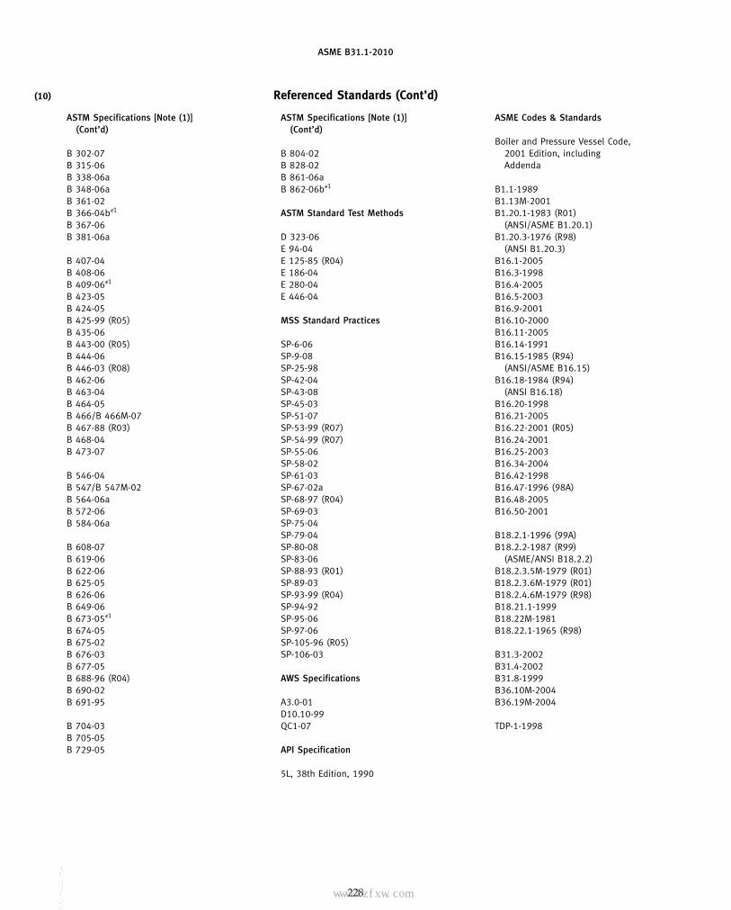
ASME B31.1-2010
(10) Referenced Standards (Cont’d)
ASTM Specifications [Note (1)] ASTM Specifications [Note (1)] ASME Codes & Standards(Cont’d) (Cont’d)
Boiler and Pressure Vessel Code,B 302-07 B 804-02 2001 Edition, includingB 315-06 B 828-02 AddendaB 338-06a B 861-06aB 348-06a B 862-06b�1 B1.1-1989B 361-02 B1.13M-2001B 366-04b�1 ASTM Standard Test Methods B1.20.1-1983 (R01)B 367-06 (ANSI/ASME B1.20.1)B 381-06a D 323-06 B1.20.3-1976 (R98)
E 94-04 (ANSI B1.20.3)B 407-04 E 125-85 (R04) B16.1-2005B 408-06 E 186-04 B16.3-1998B 409-06�1 E 280-04 B16.4-2005B 423-05 E 446-04 B16.5-2003B 424-05 B16.9-2001B 425-99 (R05) MSS Standard Practices B16.10-2000B 435-06 B16.11-2005B 443-00 (R05) SP-6-06 B16.14-1991B 444-06 SP-9-08 B16.15-1985 (R94)B 446-03 (R08) SP-25-98 (ANSI/ASME B16.15)B 462-06 SP-42-04 B16.18-1984 (R94)B 463-04 SP-43-08 (ANSI B16.18)B 464-05 SP-45-03 B16.20-1998B 466/B 466M-07 SP-51-07 B16.21-2005B 467-88 (R03) SP-53-99 (R07) B16.22-2001 (R05)B 468-04 SP-54-99 (R07) B16.24-2001B 473-07 SP-55-06 B16.25-2003
SP-58-02 B16.34-2004B 546-04 SP-61-03 B16.42-1998B 547/B 547M-02 SP-67-02a B16.47-1996 (98A)B 564-06a SP-68-97 (R04) B16.48-2005B 572-06 SP-69-03 B16.50-2001B 584-06a SP-75-04
SP-79-04 B18.2.1-1996 (99A)B 608-07 SP-80-08 B18.2.2-1987 (R99)B 619-06 SP-83-06 (ASME/ANSI B18.2.2)B 622-06 SP-88-93 (R01) B18.2.3.5M-1979 (R01)B 625-05 SP-89-03 B18.2.3.6M-1979 (R01)B 626-06 SP-93-99 (R04) B18.2.4.6M-1979 (R98)B 649-06 SP-94-92 B18.21.1-1999B 673-05�1 SP-95-06 B18.22M-1981B 674-05 SP-97-06 B18.22.1-1965 (R98)B 675-02 SP-105-96 (R05)B 676-03 SP-106-03 B31.3-2002B 677-05 B31.4-2002B 688-96 (R04) AWS Specifications B31.8-1999B 690-02 B36.10M-2004B 691-95 A3.0-01 B36.19M-2004
D10.10-99B 704-03 QC1-07 TDP-1-1998B 705-05B 729-05 API Specification
5L, 38th Edition, 1990
228
Copyright ASME International Provided by IHS under license with ASME No reproduction or networking permitted without license from IHS
--`,,```````,,```,`,`,,,,`,`,`,`-`-`,,`,,`,`,,`---
标准分享网 www.bzfxw.com 免费下载
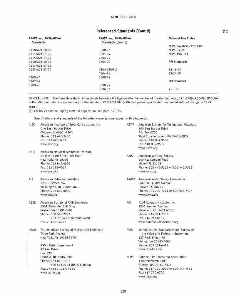
ASME B31.1-2010
(10)Referenced Standards (Cont’d)
AWWA and ANSI/AWWA AWWA and ANSI/AWWA National Fire CodesStandards Standards (Cont’d)
NFPA 54/ANSI Z223.1-06C110/A21.10-98 C300-97 NFPA 85-04C111/A21.11-95 C301-99 NFPA 1963-03C115/A21.15-99 C302-95C150/A21.50-96 C304-99 PFI StandardsC151/A21.51-96C153/A21.53-94 C500-93(95a) ES-16-08
C504-94 ES-24-08C200-97 C509-94C207-94 FCI StandardC208-96 C600-99
C606-97 79-1-03
GENERAL NOTE: The issue date shown immediately following the hyphen after the number of the standard (e.g., B1.1-1989, A 36-89, SP-6-96)is the effective date of issue (edition) of the standard. B18.2.2-1987 (R99) designates specification reaffirmed without change in 1999.
NOTE:(1) For boiler external piping material application, see para. 123.2.2.
Specifications and standards of the following organizations appear in this Appendix:
AISC ASTMAmerican Institute of Steel Construction, Inc. American Society for Testing and MaterialsOne East Wacker Drive 100 Barr Harbor DriveChicago, IL 60601-1802 P.O. Box C700Phone: 312 670-2400 West Conshohocken, PA 19428-2959Fax: 312 670-5403 Phone: 610 832-9585www.aisc.org Fax: 610 832-9555
www.astm.orgANSI American National Standards Institute
25 West 43rd Street, 4th Floor AWS American Welding SocietyNew York, NY 10036 550 NW LeJeune RoadPhone: 212 642-4900 Miami, FL 33126Fax: 212 398-0023 Phone: 305 443-9353 or 800 443-9353www.ansi.org www.aws.org
API AWWAAmerican Petroleum Institute American Water Works Association1220 L Street, NW 6666 W. Quincy AvenueWashington, DC 20005-4070 Denver, CO 80235Phone: 202 682-8000 Phone: 303 794-7711 or 800 926-7337www.api.org www.awwa.org
ASCE FCIAmerican Society of Civil Engineers Fluid Controls Institute, Inc.1801 Alexander Bell Drive 1300 Sumner AvenueReston, VA 20191-4400 Cleveland, OH 44115-2851Phone: 800 548-2723 Phone: 216 241-7333
703 295-6300 (International) Fax: 216 241-0105Fax: 703 295-6222 www.fluidcontrolsinstitute.org
ASME MSSThe American Society of Mechanical Engineers Manufacturers Standardization Society ofThree Park Avenue the Valve and Fittings Industry, Inc.New York, NY 10016-5990 127 Park Street, NE
Vienna, VA 22180-4602ASME Order Department Phone: 703 281-661322 Law Drive www.mss-hq.comBox 2900Fairfield, NJ 07007-2900 NFPA National Fire Protection AssociationPhone: 973 882-1167 1 Batterymarch Park
800-843-2763 (US & Canada) Quincy, MA 02169-7471Fax: 973 882-1717, 5155 Phone: 617 770-3000 or 800-344-3555www.asme.org Fax: 617 770-0700
www.nfpa.org
229
Copyright ASME International Provided by IHS under license with ASME No reproduction or networking permitted without license from IHS
--`,,```````,,```,`,`,,,,`,`,`,`-`-`,,`,,`,`,,`---
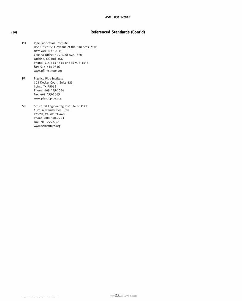
ASME B31.1-2010
(10) Referenced Standards (Cont’d)
PFI Pipe Fabrication InstituteUSA Office: 511 Avenue of the Americas, #601New York, NY 10011Canada Office: 655-32nd Ave., #201Lachine, QC H8T 3G6Phone: 514 634-3434 or 866 913-3434Fax: 514 634-9736www.pfi-institute.org
PPI Plastics Pipe Institute105 Decker Court, Suite 825Irving, TX 75062Phone: 469 499-1044Fax: 469 499-1063www.plasticpipe.org
SEI Structural Engineering Institute of ASCE1801 Alexander Bell DriveReston, VA 20191-4400Phone: 800 548-2723Fax: 703 295-6361www.seinstitute.org
230
Copyright ASME International Provided by IHS under license with ASME No reproduction or networking permitted without license from IHS
--`,,```````,,```,`,`,,,,`,`,`,`-`-`,,`,,`,`,,`---标准分享网 www.bzfxw.com 免费下载

ASME B31.1-2010
MANDATORY APPENDIX GNOMENCLATURE
This Appendix is a compilation of the nomenclature used within this Code. Included are the term definitionsand units that can be uniformly applied. These terms are also defined at a convenient location within the Code.When used elsewhere within the Code, definitions given here shall be understood to apply.
Units References
Symbol Definition SI U.S. Paragraph Table/Fig./App.
A Corrosion, erosion, and mechanical allowances mm in. 104.1.2(A)[eqs. (3), 104.3.1(G)(including threading, grooving) (4), (7), (8), (9),
(10)]104.3.1(D.2)104.3.1(G)104.4.1(B)104.5.2(B)[eq. (13)]104.5.3(A)
Area available for reinforcement:A1 in run pipe mm2 in.2 104.3.1(D.2.3) 104.3.1(D)
104.3.1(G.6) 104.3.1(G)
A2 in branch pipe mm2 in.2 104.3.1(D.2.3) 104.3.1(D)104.3.1(G.6) 104.3.1(G)
A3 by deposited metal beyond outside diameter of mm2 in.2 104.3.1(D.2.3) 104.3.1(D)run and branch and for fillet weld attachmentsof rings, pads, and saddles
A4 by reinforcing ring, pad, or integral reinforcement mm2 in.2 104.3.1(D.2.3) 104.3.1(D)104.3.1(G.6) 104.3.1(G)
A5 in saddle on right angle connection mm2 in.2 104.3.1(D.2.3) 104.3.1(D)
A6 Pressure design area expected at the end of ser- mm2 in.2 104.3.1(D.2) 104.3.1(D)vice life
A7 Required reinforcement area mm2 in.2 104.3.1(D.2.2) 104.3.1(D)104.3.1(G.5) 104.3.1(G)
B Length of miter segment at crotch mm in. 104.3.3(A&B) App. D, Table D-1
b Subscript referring to branch . . . . . . 104.3.1(D.2) 104.3.1(D)
C Cold-spring factor . . . . . . 119.10.1[eqs. (18), . . .(19)]
Cx Size of fillet weld for socket welding components mm in. . . . 127.4.4(C)other than flanges
c Flanged elbow correction factor . . . . . . . . . Table D-1Chart D-2
D Nominal pipe size mm in. 119.7.1(A.3) . . .
D1,2 Outside diameter of reducer mm in. . . . App. D, Table D-1
Dn Nominal outside diameter of pipe mm in. 102.3.2(D) . . .
231
(10)
Copyright ASME International Provided by IHS under license with ASME No reproduction or networking permitted without license from IHS
--`,,```````,,```,`,`,,,,`,`,`,`-`-`,,`,,`,`,,`---

ASME B31.1-2010
Units References
Symbol Definition SI U.S. Paragraph Table/Fig./App.
Do Outside diameter of pipe mm in. 102.3.2(D) App. D, Table D-1104.1.2(A)[eqs. (7), 104.1.2(A)
(9)]104.8.1[eq. (15)]104.8.2[eq. (16)]
Dob Outside diameter of branch mm in. 104.3.1(D.2) App. D, Fig. D-1104.3.1(D.2.3) 104.3.1(G)104.3.1(E)104.3.1(G.4)104.3.1(G.5)
Doh Outside diameter of header or run pipe mm in. 104.3.1(D.2) 104.3.1(G)104.3.1(E)104.3.1(G.4)104.3.1(G.5)
d Inside diameter of pipe mm in. 104.1.2(A)[eqs. (8), 104.1.2(A)(10)]
d1 Inside centerline longitudinal direction of the fin- mm in. 104.3.1(D) 104.3.1(D)ished branch opening in the run of the pipe 104.3.1(E)
d2 Half-width of reinforcement zone mm in. 104.3.1(D.2) 104.3.1(D)d5 Diameter of finished opening mm in. 104.4.2 . . .d6 Inside or pitch diameter of gasket mm in. 104.5.3(A)[eq. (14)] 104.5.3db Corroded internal diameter of branch pipe mm in. 104.3.1(G.4) 104.3.1(G)dc Corroded internal diameter of extruded outlet mm in. 104.3.1(G.4) 104.3.1(G)
104.3.1(G.5)104.3.1(G.6)
di Inside diameter of Y-globe valve mm in. . . . 122.1.7(C)dn Nominal inside diameter of pipe mm in. 102.3.2(D) . . .dr Corroded internal diameter of run mm in. 104.3.1(G.4) 104.3.1(G)E Weld joint efficiency factor . . . . . . 104.1.2(A.5) 102.4.3
App. A Notes andTables
E Young’s modulus of elasticity (used with sub- MPa psi 119.6.2 App. C, Tablesscripts) 119.6.4 C-1 and C-2
119.10.1[eqs. (18), App. D, Table D-1(19)]
F Casting quality factor . . . . . . 104.1.2(A.5) App. A Notes andTables
f Stress range reduction factor . . . . . . 102.3.2(C)[eq. (1)] 102.3.2(C)h Subscript referring to run or header . . . . . . 104.3.1(D.2) 104.3.1(D)
104.3.1(G)h Thread depth (ref. ASME B1.20.1) mm in. 102.4.2 . . .h Flexibility characteristic, to compute i, k . . . . . . . . . App. D, Table D-1ho Height of extruded lip mm in. 104.3.1(G.2) 104.3.1(G)
104.3.1(G.4)I Lorenz equation compensation factor . . . . . . 102.4.5[eqs. (3), (4), . . .
(5), (6)]i Stress intensification factor . . . . . . 104.8.1[eq. (15)] App. D, Table D-1
104.8.2[eq. (16)]104.8.3[eq. (17)]104.8.4(C)
j Subscript for resultant moment . . . . . . 104.8.4(A) . . .K Factor for reinforcing area . . . . . . 104.3.1(G.5) 104.3.1(G)k Factor for occasional loads . . . . . . 104.8.2[eq. (16)] . . .k Flexibility factor . . . . . . . . . App. D, Table D-1L Developed length of line axis m ft 119.7.1(A.3) . . .L1 Height of nozzle mm in. 104.8.4(C) App. D, Fig. D-1L4 Altitude of reinforcing zone outside run pipe mm in. 104.3.1(D.2) 104.3.1(D)L8 Altitude of reinforcing zone for extruded outlet mm in. 104.3.1(G.4) 104.3.1(G)
104.3.1(G.6)
232
Copyright ASME International Provided by IHS under license with ASME No reproduction or networking permitted without license from IHS
--`,,```````,,```,`,`,,,,`,`,`,`-`-`,,`,,`,`,,`---
标准分享网 www.bzfxw.com 免费下载

ASME B31.1-2010
Units References
Symbol Definition SI U.S. Paragraph Table/Fig./App.
M Moment of bending or torsional force (used with mm·N in.-lb 104.8.1[eq. (15)] 104.8.4subscripts to define applications as shown in 104.8.2[eq. (16)]referenced paragraphs) 104.8.3[eq. (17)]
104.8.4(A)104.8.4(C)
MAWP Maximum allowable working pressure kPa psi 100.2 . . .
MSOP Maximum sustained operating pressure kPa psi 101.2.2 . . .
N Total number of equivalent reference displace- . . . . . . 102.3.2(C)[eq. (2)] 102.3.2(C)ment stress range cycles
NE Number of cycles of reference displacement . . . . . . 102.3.2(C)[eq. (2)] . . .stress range
Ni Number of cycles associated with displacement . . . . . . 102.3.2(C)[eq. (2)] . . .stress range
NPS Nominal pipe size . . . in. General . . .
P Internal design gage pressure of pipe, component kPa psi 102.3.2(D) App. D, Table D-1104.1.2(A)[eqs. (7),
(8), (9), (10)]104.5.1(A)104.5.2(B)104.5.3(A)[eq. (14)]104.5.3(B)104.8.1[eq. (15)]104.8.2[eq. (16)]122.1.2(A)122.1.3(A)122.1.4(A)122.1.4(B)122.1.6(B)122.1.7(C)122.4(B)
q Ratio of partial �T to maximum �T (used with . . . . . . 102.3.2(C)[eq. (2)] . . .subscripts)
R Reaction moment in flexibility analysis (used with mm-N in.-lb 119.10.1[eqs. (18), . . .subscripts) (19)]
R Centerline radius of elbow or bend, and effective mm in. 102.4.5(B) App. D, Table D-1“radius” of miter bends 104.3.3(C.3.1) 102.4.5
Rm Mean radius of run pipe mm in. . . . App. D, Fig. D-1App. D, Table D-1
r Mean radius of pipe using nominal wall tn mm in. 104.3.3 App. D, Table D-1
r1 Half width of reinforcement zone mm in. 104.3.1(G.4) 104.3.1(G)
r1, r2, r3 Transition radii of branch reinforcement mm in. . . . App. D, Fig. D-1
rb Branch mean cross-sectional radius mm in. 104.8.4 . . .
ri Inside radius of branch mm in. 104.8.4(C) App. D, Fig. D-1
r ′m Mean radius of branch mm in. 104.8.4(C) App. D, Fig. D-1App. D, Table D-1
ro Radius of curvature of external curved portion mm in. 104.3.1(G.2) 104.3.1(G)104.3.1(G.4)104.3.1(G.6)
rp Outside radius of branch reinforcement mm in. . . . App. D, Fig. D-1App. D, Table D-1
233
Copyright ASME International Provided by IHS under license with ASME No reproduction or networking permitted without license from IHS
--`,,```````,,```,`,`,,,,`,`,`,`-`-`,,`,,`,`,,`---

ASME B31.1-2010
Units References
Symbol Definition SI U.S. Paragraph Table/Fig./App.
rx External crotch radius of welded-in contour mm in. . . . App. Dinserts
S Basic material allowable stress MPa psi 122.1.2(A) . . .122.1.3(B)122.4(B.3)
S Basic material allowable stress MPa ksi 102.3.1(A) App. A Tablesand Notes
Sa Bolt design stress at atmospheric temperature kPa psi 104.5.1(A) . . .
Sb Bolt design stress at design temperature kPa psi 104.5.1(A) . . .
Sc Basic material allowable stress at minimum (cold) MPa psi 102.3.2(C)[eq. (1)] . . .temperature
Sf Allowable stress for flange material or pipe kPa psi 104.5.1(A) . . .
Sh Basic material allowable stress at maximum (hot) MPa psi 102.3.2(C)[eq. (1)] . . .temperature 102.3.2(D)
104.8.1[eq. (15)]104.8.2[eq. (16)]104.8.3[eq. (17)]119.10.1 [eq. (19)]
Slp Longitudinal pressure stress kPa psi 102.3.2(D) . . .104.8
SA Allowable stress range for expansion stress MPa psi 102.3.2(C)[eq. (1)] . . .104.8.3[eq. (17)]
SE Computed thermal expansion stress range MPa psi 104.8.3[eq. (17)] . . .119.6.4119.10.1[eq. (19)]
SL Longitudinal stress due to pressure, weight, and MPa psi 102.3.2(D) . . .other sustained loads 104.8.1[eq. (15)]
SE Allowable stress (including weld joint efficiency MPa psi 102.3.2(C) . . .factor) 104.1.2(A)[eqs. (7),
(8), (9), (10)]104.5.2(B)104.5.3(A)[eq. (14)]104.5.3(B)
SE Allowable stress (including weld joint efficiency MPa ksi 102.3.1(A) App. A Tablesfactor) and Notes
SF Allowable stress (including casting quality factor) MPa psi 104.1.2(A) . . .
SF Allowable stress (including casting quality factor) MPa ksi 102.3.1(A) App. A Tablesand Notes
s Miter spacing pipe centerline mm in. . . . App. D, Table D-1
T Pipe wall thickness (measured or minimum, in mm in. 104.3.1(D.2) 104.3.1(D)accordance with purchase specification used 104.8.4(C) App. D, Fig. D-1with or without subscripts), viz.,
Tbpthickness of branchThpthickness of header, etc.
Tc Crotch thickness of welded-in contour inserts mm in. . . . App. D, Table D-1
234
Copyright ASME International Provided by IHS under license with ASME No reproduction or networking permitted without license from IHS
--`,,```````,,```,`,`,,,,`,`,`,`-`-`,,`,,`,`,,`---
标准分享网 www.bzfxw.com 免费下载

ASME B31.1-2010
Units References
Symbol Definition SI U.S. Paragraph Table/Fig./App.
To Corroded finished thickness extruded outlet mm in. 104.3.1(G.4) 104.3.1(G)104.3.1(G.6)
t Pressure design thickness pipe, components mm in. 104.1.2(A)[eqs. (7), 104.3.1(G)(used with subscripts) (8), (9), (10)] 104.5.3
104.3.1(D.2) 127.4.8(D)104.3.1(G.4)104.3.3(C.3.1)104.3.3(C.3.2)104.4.1(B)104.4.2104.5.2(B)[eq. (13)]104.5.3(A)[eq. (14)]104.5.3(B)104.8.1104.8.4(C)127.4.8(B)132.4.2(E)
t1,2 Nominal wall thickness of reducer mm in. . . . App. D, Table D-1
tb Required thickness of branch pipe mm in. 104.3.1(G.4) 104.3.1(G)104.3.1(G.6)
tc Throat thickness of cover fillet weld, branch con- mm in. 127.4.8(B) 127.4.8(D)nection 132.4.2(E) 127.4.8(E)
te Effective branch wall thickness mm in. 104.8.4(C) . . .
th Required thickness of header or run mm in. 104.3.1(G.4) 104.3.1(G)
tm Minimum required thickness of component, mm in. 104.1.2(A)[eqs. (7), 102.4.5including allowances (c) for mechanical joining, (8), (9), (10)] 104.1.2(A)corrosion, etc. (used with subscripts), viz., 104.3.1(D.2) 104.3.1(D)
tmbpminimum thickness of branch 104.3.1(E) 104.3.1(G)tmhpminimum thickness of header 104.3.1(G) 127.4.2
104.3.3(C.3.1)104.3.3(C.3.2)104.4.1(B)104.5.2(B)[eq. (13)]104.5.3(A)
tn Nominal wall thickness of component (used with mm in. 102.3.2(D) 127.4.4(B)subscripts), viz., 104.3.1(G) 127.4.4(C)
tnbpnominal wall thickness of branch 104.3.3 127.4.8(D)tnhpnominal wall thickness of header 104.8.1[eq. (15)] 127.4.8(E)tnrpnominal thickness of reinforcement 104.8.2[eq. (16)] App. D, Fig. D-1
104.8.4(C) App. D, Table D-1127.4.8(B)132.4.2(E)
tr Thickness of reinforcing pad or saddle mm in. 104.3.1(D.2) 104.3.1(D)104.3.1(E) App. D, Table D-1
ts Wall thickness of segment or miter mm in. 104.3.3(C.3) . . .
tw Weld thickness mm in. 104.3.1(C.2) 127.4.8(G)
U Anchor distance (length of straight line joining m ft 119.7.1(A.3) . . .anchors)
W Weld strength reduction factor . . . . . . 102.4.7 102.4.7104.1.4
235
Copyright ASME International Provided by IHS under license with ASME No reproduction or networking permitted without license from IHS
--`,,```````,,```,`,`,,,,`,`,`,`-`-`,,`,,`,`,,`---

ASME B31.1-2010
Units References
Symbol Definition SI U.S. Paragraph Table/Fig./App.
xmin Size of fillet weld for slip-on and socket welding mm in. . . . 127.4.4(B)flanges or socket wall for socket welds
Y Resultant of movement to be absorbed by pipe- . . . . . . 119.7.1(A.3) . . .lines
y A coefficient having values given in Table . . . . . . 104.1.2(A.7)[eqs. 104.1.2(A)104.1.2(A) (7), (8), (9), (10)] App. A, Notes to
Tables A-4, A-5,A-6, A-7, andA-9
y Branch offset dimension mm in. . . . App. D, Fig. D-1
Z Section modulus of pipe mm3 in.3 104.8.1[eq. (15)] . . .104.8.2[eq. (16)]104.8.3[eq. (17)]104.8.4(A)104.8.4(C)
� Angle between axes of branch and run deg deg 104.3.1(D.2) 104.3.1(D)104.3.1(E)
� Reducer cone angle deg deg . . . App. D, Table D-1
� Mismatch or offset mm in. . . . App. D, Table D-1
�T Range of temperature change (used with sub- °C °F 102.3.2(C) . . .scripts)
� Angle of miter cut deg deg 104.3.3 App. D, Table D-1
�n Transition angle of branch reinforcement deg deg . . . App. D, Fig. D-1
≥ Equal to or greater than . . . . . . . . . . . .
≤ Equal to or less than . . . . . . . . . . . .
236
Copyright ASME International Provided by IHS under license with ASME No reproduction or networking permitted without license from IHS
--`,,```````,,```,`,`,,,,`,`,`,`-`-`,,`,,`,`,,`---
标准分享网 www.bzfxw.com 免费下载

ASME B31.1-2010
MANDATORY APPENDIX HPREPARATION OF TECHNICAL INQUIRIES
H-1 INTRODUCTION
The ASME B31 Committee, Code for Pressure Piping,will consider written requests for interpretations andrevisions of the Code rules, and develop new rules ifdictated by technical development. The Committee’sactivities in this regard are limited strictly to interpreta-tions of the rules or to the consideration of revisions tothe present rules on the basis of new data or technology.The Introduction to this Code states “It is the owner’sresponsibility to determine which Code Section is appli-cable to a piping installation.” The Committee will notrespond to inquiries requesting assignment of a CodeSection to a piping installation. As a matter of publishedpolicy, ASME does not approve, certify, rate, or endorseany item, construction, proprietary device, or activity,and, accordingly, inquiries requiring such considerationwill be returned. Moreover, ASME does not act as aconsultant on specific engineering problems or on thegeneral application or understanding of the Code rules.If, based on the inquiry information submitted, it is theopinion of the Committee that the inquirer should seekprofessional assistance, the inquiry will be returned withthe recommendation that such assistance be obtained.
Inquiries that do not provide the information neededfor the Committee’s full understanding will be returned.
H-2 REQUIREMENTS
Inquiries shall be limited strictly to interpretations ofthe rules or to the consideration of revisions to the pres-ent rules on the basis of new data or technology. Inquiriesshall meet the following requirements:
237
(a) Scope. Involve a single rule or closely related rulesin the scope of the Code. An inquiry letter concerningunrelated subjects will be returned.
(b) Background. State the purpose of the inquiry,which may be either to obtain an interpretation of Coderules, or to propose consideration of a revision to thepresent rules. Provide concisely the information neededfor the Committee’s understanding of the inquiry, beingsure to include reference to the applicable Code Section,Edition, Addenda, paragraphs, figures, and tables. Ifsketches are provided, they shall be limited to the scopeof the inquiry.
(c) Inquiry Structure(1) Proposed Question(s). The inquiry shall be stated
in a condensed and precise question format, omittingsuperfluous background information, and, whereappropriate, composed in such a way that “yes” or “no”(perhaps with provisos) would be an acceptable reply.The inquiry statement should be technically and editori-ally correct.
(2) Proposed Reply(ies). Provide a proposed replystating what it is believed that the Code requires. If inthe inquirer’s opinion, a revision to the Code is needed,recommended wording shall be provided in addition toinformation justifying the change.
H-3 SUBMITTALInquiries should be submitted in typewritten form;
however, legible handwritten inquiries will be consid-ered. They shall include the name and mailing addressof the inquirer, and be mailed to the following address:
SecretaryASME B31 CommitteeThree Park AvenueNew York, NY 10016-5990
Copyright ASME International Provided by IHS under license with ASME No reproduction or networking permitted without license from IHS
--`,,```````,,```,`,`,,,,`,`,`,`-`-`,,`,,`,`,,`---
ASME B31.1-2010
MANDATORY APPENDIX JQUALITY CONTROL REQUIREMENTS FOR
BOILER EXTERNAL PIPING (BEP)
FOREWORD
This Appendix contains the quality control require-ments for boiler external piping. The following is thatportion of Appendix A-300 Quality Control System ofthe ASME Boiler and Pressure Vessel Code, Section I,which is applicable to BEP.
J-1 QUALITY CONTROL SYSTEM
J-1.1 General
J-1.1.1 Quality Control System. The Manufactureror assembler shall have and maintain a quality controlsystem which will establish that all Code requirements,including material, design, fabrication, examination (bythe Manufacturer), and inspection of boilers and boilerparts (by the Authorized Inspector), will be met. Pro-vided that Code requirements are suitably identified,the system may include provisions for satisfying anyrequirements by the Manufacturer or user that exceedminimum Code requirements and may include provi-sions for quality control of non-Code work. In such sys-tems, the Manufacturer may make changes in parts ofthe system that do not affect the Code requirementswithout securing acceptance by the Authorized Inspec-tor. Before implementation, revisions to quality controlsystems of Manufacturers and assemblers of safety andsafety relief valves shall have been found acceptable toan ASME designee if such revisions affect Coderequirements.
The system that the Manufacturer or assembler usesto meet the requirements of this Section must be onesuitable for his/her own circumstances. The necessaryscope and detail of the system shall depend on the com-plexity of the work performed and on the size and com-plexity of the Manufacturer ’s (or assembler ’s)organization. A written description of the system theManufacturer or assembler will use to produce a Codeitem shall be available for review. Depending upon thecircumstances, the description may be brief orvoluminous.
The written description may contain information ofproprietary nature relating to the Manufacturer’s (orassembler’s) processes. Therefore, the Code does notrequire any distribution of this information, except forthe Authorized Inspector or ASME designee.
238
It is intended that information learned about the sys-tem in connection with evaluation will be treated asconfidential and that all loaned descriptions will bereturned to the Manufacturer upon completion of theevaluation.
J-1.2 Outline of Features to Be Included in theWritten Description of the Quality ControlSystem
The following is a guide to some of the features thatshould be covered in the written description of the qual-ity control system and that is equally applicable to bothshop and field work.
J-1.2.1 Authority and Responsibility. The authorityand responsibility of those in charge of the quality con-trol system shall be clearly established. Persons per-forming quality control functions shall have sufficientand well-defined responsibility, the authority, and theorganizational freedom to identify quality control prob-lems and to initiate, recommend, and provide solutions.
J-1.2.2 Organization. An organization chart show-ing the relationship between management and engi-neering, purchasing, manufacturing, field assembling,inspection, and quality control is required to reflect theactual organization. The purpose of this chart is to iden-tify and associate the various organizational groups withthe particular function for which they are responsible.The Code does not intend to encroach on the Manufac-turer’s right to establish, and from time to time to alter,whatever form of organization the Manufacturer consid-ers appropriate for its Code work.
J-1.2.3 Drawings, Design Calculations, and Specifica-tion Control. The Manufacturer’s or assembler’s qualitycontrol system shall provide procedures that will ensurethat the latest applicable drawings, design calculations,specifications, and instructions, required by the Code,as well as authorized changes, are used for manufacture,assembly, examination, inspection, and testing.
J-1.2.4 Material Control. The Manufacturer orassembler shall include a system of receiving controlthat will ensure that the material received is properlyidentified and has documentation, including requiredmaterial certifications or material test reports, to satisfy
Copyright ASME International Provided by IHS under license with ASME No reproduction or networking permitted without license from IHS
--`,,```````,,```,`,`,,,,`,`,`,`-`-`,,`,,`,`,,`---
标准分享网 www.bzfxw.com 免费下载

ASME B31.1-2010
Code requirements as ordered. The material control sys-tem shall insure that only the intended material is usedin Code construction.
J-1.2.5 Examination and Inspection Program. TheManufacturer’s quality control system shall describe thefabrication operations, including examinations, suffi-ciently to permit the Authorized Inspector to determineat what stages specific inspections are to be performed.
J-1.2.6 Correction of Nonconformities. There shallbe a system agreed upon with the Authorized Inspectorfor correction of nonconformities. A nonconformity isany condition that does not comply with the applicablerules of this Section. Nonconformities must be correctedor eliminated in some way before the completed compo-nent can be considered to comply with this Section.
J-1.2.7 Welding. The quality control system shallinclude provisions for indicating that welding conformsto requirements of Section IX as supplemented by thisSection.
J-1.2.8 Nondestructive Examination. The qualitycontrol system shall include provisions for identifyingnondestructive examination procedures theManufacturer will apply to conform with requirementsof this Section.
J-1.2.9 Heat Treatment. The quality control systemshall provide controls to ensure that heat treatments asrequired by the rules of this Section are applied. Meansshall be indicated by which the Authorized Inspectorcan satisfy him/herself that these Code heat treatmentrequirements are met. This may be by review of furnacetime – temperature records or by other methods asappropriate.
J-1.2.10 Calibration of Measurement and TestEquipment. The Manufacturer or assembler shall havea system for the calibration of examination, measuring,and test equipment used in fulfillment of requirementsof this Section.
J-1.2.11 Records Retention. The Manufacturer orassembler shall have a system for the maintenance ofradiographs and Manufacturers’ Data Reports asrequired by this Section.
J-1.2.12 Sample Forms. The forms used in the qual-ity control system and any detailed procedures for theiruse shall be available for review. The written descriptionshall make necessary references to these forms.
239
J-1.2.13 Inspection of Boilers and Boiler Parts
J-1.2.13.1 Inspection of boilers and boiler partsshall be by the Authorized Inspector described in PG-91.
J-1.2.13.2 The written description of the qualitycontrol system shall include reference to the AuthorizedInspector.
J-1.2.13.2.1 The Manufacturer (or assembler)shall make available to the Authorized Inspector at theManufacturer’s plant (or construction site) a currentcopy of the written description or the applicable qualitycontrol system.
J-1.2.13.2.2 The Manufacturer’s quality controlsystem shall provide for the Authorized Inspector at theManufacturer’s plant to have access to all drawings,calculations, specifications, procedures, process sheets,repair procedures, records, test results, and any otherdocuments as necessary for the Inspector to performhis/her duties in accordance with this Section. TheManufacturer may provide such access either to his/herown files of such documents or by providing copies tothe Inspector.
J-1.2.14 Inspection of Safety and Safety Relief Valves
J-1.2.14.1 Inspection of safety and safety reliefvalves shall be by designated representative of theASME, as described in PG-73.3.
J-1.2.14.2 The written description of the qualitycontrol system shall include reference to the ASMEdesignee.
J-1.2.14.2.1 The valve Manufacturer (or assem-bler) shall make available to the ASME designee at theManufacturer ’s plant a current copy of the writtendescription of the applicable quality control system.
J-1.2.14.2.2 The valve Manufacturer ’s (orassembler’s) quality control system shall provide for theASME designee to have access to all drawings, calcula-tions, specifications, procedures, process sheets, repairprocedures, records, test results, and any other docu-ments as necessary for the designee to perform his/herduties in accordance with this Section. The Manufacturermay provide such access either to his/her own files ofsuch documents or by providing copies to the designee.
Copyright ASME International Provided by IHS under license with ASME No reproduction or networking permitted without license from IHS
--`,,```````,,```,`,`,,,,`,`,`,`-`-`,,`,,`,`,,`---

ASME B31.1-2010
NONMANDATORY APPENDICES
NONMANDATORY APPENDIX IIRULES FOR THE DESIGN OF SAFETY VALVE INSTALLATIONS1
FOREWORD
ASME B31.1 contains rules governing the design, fab-rication, materials, erection, and examination of powerpiping systems. Experience over the years has demon-strated that these rules may be reasonably applied tosafety valve installations. Nevertheless, instances haveoccurred wherein the design of safety valve installationsmay not have properly and fully applied the ASME B31.1rules. Accordingly, this nonmandatory Appendix toASME B31.1 has been prepared to illustrate and clarifythe application of ASME B31.1 rules to safety valveinstallations. To this end, Appendix II presents thedesigner with design guidelines and alternative designmethods.
II-1 SCOPE AND DEFINITION
II-1.1 Scope
The scope of Appendix II is confined to the design ofthe safety valve installations as defined in para. 1.2 ofthis Appendix. The loads acting at the safety valve sta-tion will affect the bending moments and stresses inthe complete piping system, out to its anchors and/or extremities, and it is the designer’s responsibility toconsider these loads. Appendix II, however, deals pri-marily with the safety valve installation, and not thecomplete piping system.
The design of the safety valve installation requiresthat careful attention be paid to
(A) all loads acting on the system(B) the forces and bending moments in the piping
and piping components resulting from the loads(C) the loading and stress criteria(D) general design practicesAll components in the safety valve installation must
be given consideration, including the complete piping
1 Nonmandatory appendices are identified by a Roman numeral;mandatory appendices are identified by a letter. Therefore, Romannumeral I is not used, in order to avoid confusion with the letter I.
240
system, the connection to the main header, the safetyvalve, valve and pipe flanges, the downstream dischargeor vent piping, and the system supports. The scope ofthis Appendix is intended to cover all loads on all com-ponents. It is assumed that the safety valve complieswith the requirements of American National Standardsprescribed by ASME B31.1 for structural integrity.
This Appendix has application to either safety, relief,or safety-relief valve installations. For convenience,however, the overpressure protection device is generallyreferred to as a safety valve. The loads associated withrelief or safety-relief valve operation may differ signifi-cantly from those of safety valve operation, but other-wise the rules contained herein are equally applicableto each type of valve installation. See para. II-1.2 fordefinition.
This Appendix provides analytic and nomenclaturedefinition figures to assist the designer, and is notintended to provide actual design layout (drains, drippans, suspension, air gaps, flanges, weld ends, and otherdesign details are not shown). Sample problems havebeen provided at the end of the text to assist the designerin application of the rules in this Appendix.
II-1.2 Definitions (Valve Descriptions Follow theDefinitions Given in Section I of the ASMEBoiler and Pressure Vessel Code)
safety valve: an automatic pressure relieving device actu-ated by the static pressure upstream of the valve andcharacterized by full opening pop action. It is used forgas or vapor service.
relief valve: an automatic pressure relieving device actu-ated by the static pressure upstream of the valve thatopens further with the increase in pressure over theopening pressure. It is used primarily for liquid service.
safety relief valve: an automatic pressure actuated reliev-ing device suitable for use either as a safety valve orrelief valve, depending on application.
Copyright ASME International Provided by IHS under license with ASME No reproduction or networking permitted without license from IHS
--`,,```````,,```,`,`,,,,`,`,`,`-`-`,,`,,`,`,,`---标准分享网 www.bzfxw.com 免费下载

ASME B31.1-2010
power-actuated pressure relieving valve: a relieving devicewhose movements to open or close are fully controlledby a source of power (electricity, air, steam, or hydraulic).The valve may discharge to atmosphere or to a containerat lower pressure. The discharge capacity may beaffected by the downstream conditions, and such effectsshall be taken into account. If the power-actuated pres-sure relieving valves are also positioned in responseto other control signals, the control impulse to preventoverpressure shall be responsive only to pressure andshall override any other control function.
open discharge installation: an installation where the fluidis discharged directly to the atmosphere or to a vent pipethat is uncoupled from the safety valve. Figure II-1-2(A)shows a typical open discharge installation with anelbow installed at the valve discharge to direct the flowinto a vent pipe. The values for l and m on Fig. II-1-2(A)are upper limits for which the rules for open dischargesystems may be used. l shall be limited to a value lessthan or equal to 4Do; m shall be limited to a value lessthan or equal to 6Do where Do is the outside diameterof the discharge pipe. Open discharge systems whichdo not conform to these limits shall be evaluated by thedesigner for the applicability of these rules.
closed discharge installation: an installation where theeffluent is carried to a distant spot by a discharge pipewhich is connected directly to the safety valve.Figure II-1-2(B) shows a typical closed discharge system.
safety valve installation: the safety valve installation isdefined as that portion of the system shown onFigs. II-1-2(A) and II-1-2(B). It includes the run pipe,branch connection, the inlet pipe, the valve, the dis-charge piping, and the vent pipe. Also included are thecomponents used to support the system for all staticand dynamic loads.
II-2 LOADS
II-2.1 Thermal Expansion
Loads acting on the components in the safety valveinstallation and the displacements at various points dueto thermal expansion of the piping shall be determinedby analyzing the complete piping system out to itsanchors, in accordance with procedures in para. 119.
II-2.1.1 Installations With Open Discharge. Forsafety valve installations with open discharge, there willbe no thermal expansion loads acting on the dischargeelbow, the valve, or the valve inlet other than that fromrestraint to thermal expansion as described below.Restraint to thermal expansion can sometimes occur dueto drain lines, or when structural supports are providedto carry the reaction forces associated with safety valvelift. Examples of such structural supports are shown inFig. II-6-1, sketch (b). When such restraints exist, the
241
thermal expansion loads and stresses shall be calculatedand effects evaluated.
II-2.1.2 Installations With Closed Discharge. Loadsdue to thermal expansion and back pressure of a safetyvalve installation with a closed discharge can be highenough to cause malfunction of the valve, excessive leak-age of the valve or flange, or overstress of other compo-nents. The loads due to thermal expansion shall beevaluated for all significant temperature combinations,including the cases where the discharge piping is hotfollowing safety valve operation.
II-2.2 Pressure
Pressure loads acting on the safety valve installationare important from two main considerations. The firstconsideration is that the pressure acting on the walls ofthe safety valve installation can cause membrane stresseswhich could result in rupture of the pressure retainingparts. The second consideration is that the pressureeffects associated with discharge can cause high loadsacting on the system which create bending momentsthroughout the piping system. These pressure effectsare covered in para. II-2.3.
All parts of the safety valve installation must bedesigned to withstand the design pressures withoutexceeding the Code allowable stresses. The branch con-nection, the inlet pipe, and the inlet flanges shall bedesigned for the same design pressure as that of the runpipe. The design pressure of the discharge system willdepend on the safety valve rating and on the configura-tion of the discharge piping. The open discharge installa-tion and the closed discharge installation presentsomewhat different problems in the determination ofdesign pressures, and these problems are discussed inthe paragraphs below.
II-2.2.1 Design Pressure and Velocity for OpenDischarge Installation Discharge Elbows and VentPipes. There are several methods available to thedesigner for determining the design pressure and veloc-ity in the discharge elbow and vent pipe. It is the respon-sibility of the designer to assure himself that the methodused yields conservative results. A method for determin-ing the design pressures and velocities in the dischargeelbow and vent pipe for open discharge installation isshown below and illustrated in the sample problem.
(A) First, calculate the design pressure and velocityfor the discharge elbow.
(A.1) Determine the pressure, P1, that exists at thedischarge elbow outlet (Fig. II-2-1).
P1 pWA1
(b − 1)b � 2(ho − a)J
gc (2b − 1)
Copyright ASME International Provided by IHS under license with ASME No reproduction or networking permitted without license from IHS
--`,,```````,,```,`,`,,,,`,`,`,`-`-`,,`,,`,`,,`---

ASME B31.1-2010
Fig. II-1-2(A) Safety Valve Installation (Open Discharge System)
Run pipe
Branch connection
Inlet pipe
Inlet flanges
Inlet weld
Safety valve
Vent pipe
Outlet flanges
m
Dischargepipe
Do
l
242
Copyright ASME International Provided by IHS under license with ASME No reproduction or networking permitted without license from IHS
--`,,```````,,```,`,`,,,,`,`,`,`-`-`,,`,,`,`,,`---
标准分享网 www.bzfxw.com 免费下载

ASME B31.1-2010
Fig. II-1-2(B) Safety Valve Installation (Closed Discharge System)
Receiver
Closed dischargepipe
Outlet flanges
Inlet weldInlet flanges
Safety valve
Inlet pipe
Run pipe
Branch connection
243
Copyright ASME International Provided by IHS under license with ASME No reproduction or networking permitted without license from IHS
--`,,```````,,```,`,`,,,,`,`,`,`-`-`,,`,,`,`,,`---

ASME B31.1-2010
Fig. II-2-1 Discharge Elbow (Open Discharge Installation)
Point 1
F1 = + (P1 − Pa)A1WV1gc
Point 1a
(A.2) Determine the velocity, V1, that exists at thedischarge elbow outlet (Fig. II-2-1).
V1 p �2gcJ(ho − a)(2b − 1)
whereA1 p discharge elbow area, in.2
gc p gravitational constantp 32.2 lbm-ft/lbf-sec2
ho p stagnation enthalpy at the safety valve inlet,Btu/lbm
J p 778.16 ft-lbf/BtuP1 p pressure, psia (lbf/in.2, absolute)V1 p ft/secW p actual mass flow rate, lbm/sec
Common values of a and b are listed in Table II-2.2.1.(A.3) Determine the safety valve outlet pressure,
P1a, at the inlet to the discharge elbow (Fig. II-2-1).(A.3.1) Determine the length to diameter ratio
(dimensionless) for the pipe sections in the dischargeelbow (L/D)
L/D pLmax
D
(A.3.2) Determine a Darcy-Weisbach friction fac-tor, f, to be used. (For steam, a value of 0.013 can beused as a good estimate since f will vary slightly inturbulent pipe flow.)
244
Table II-2.2.1 Values of a and b
Steam Condition a, Btu/lbm b
Wet steam, 291 11< 90% quality
Saturated steam, 823 4.33≥ 90% quality,15 psia ≤ P1 ≤ 1,000 psia
Superheated steam, 831 4.33≥ 90% quality,1,000 psia < P1 ≤ 2,000 psia1
NOTE:(1) This method may be used as an approximation for pressures
over 2,000 psi, but an alternate method should be used forverification.
(A.3.3) Determine a specific heat ratio (for super-heated steam, k p 1.3 can be used as an estimate — forsaturated steam, k p 1.1).
(A.3.4) Calculate f(Lmax/D).(A.3.5) Enter Chart II-1 with value of f(Lmax/D)
and determine P/P*.(A.3.6) P1a p P1 (P/P*).(A.3.7) P1a is the maximum operating pressure of
the discharge elbow.(B) Second, determine the design pressure and veloc-
ity for the vent pipe.
Copyright ASME International Provided by IHS under license with ASME No reproduction or networking permitted without license from IHS
--`,,```````,,```,`,`,,,,`,`,`,`-`-`,,`,,`,`,,`---
标准分享网 www.bzfxw.com 免费下载

ASME B31.1-2010
Chart II-1 Compressible Flow Analysis
0.50.41 × 100
1 × 10⁻¹
1 × 10⁻²
8
6
4
2
8
6
4
2
1.1 1.2 1.3 1.4 1.5
P/P*
P/P*
V/V*
V/V*
1.6 1.7 1.8
0.6 0.7 0.8 0.9 1.0 1.1
k = 1.4
k = 1.4k = 1.3k = 1.2k = 1.1k = 1.0
k = 1.3k = 1.2k = 1.1k = 1.0
L m
ax.
Df
()
Fanno lines: one-dimensionalcompressible-flow functionsfor adiabatic flow at constantarea with friction. From gastables by Keenan and Kaye,1948
(B.1) Determine the pressure, P3, that exists at thevent pipe outlet (Fig. II-2-2)
P3 p P1 �A1
A3�(B.2) Determine the velocity, V3, that exists at the
vent pipe outlet (Fig. II-2-2)
V3 p V1
(B.3) Repeat Steps (3.1) to (3.7) in the calculationof the discharge elbow maximum operating pressureto determine the maximum operating pressure of thevent pipe.
(B.4) Determine the velocity, V2, and pressure, P2,that exist at the inlet to the vent pipe (Fig. II-2-2).
245
(B.4.1) Enter Chart II-12 with value of f(Lmax/D)from Step (3.4) and determine values of V/V* and P/P*.
(B.4.2) Calculate V2
V2 p V3 (V/V*)
(B.4.3) P2 p P3 (P/P*). This is the highest pressurethe vent stack will see and should be used in calculatingvent pipe blowback (see para. II-2.3.1.2).
II-2.2.2 Pressure for Closed Discharge Installations.The pressures in a closed discharge pipe during steady
2 Chart II-1 may be extended to other values of f (Lmax/D) byuse of the Keenan and Kaye Gas Tables for Fanno lines. The Darcy-Weisbach friction factor is used in Chart II-1, whereas the GasTables use the Fanning factor which is one-fourth the value of theDarcy-Weisbach factor.
Copyright ASME International Provided by IHS under license with ASME No reproduction or networking permitted without license from IHS
--`,,```````,,```,`,`,,,,`,`,`,`-`-`,,`,,`,`,,`---

ASME B31.1-2010
Fig. II-2-2 Vent Pipe (Open Discharge Installation)
2
3
1
Sufficient overlap to preventthe discharge elbow from pullingout of the vent pipe due to openingreaction and/or displacementresulting from expansion movements
φ
θ
F3F3 =
F3
+ (P3 − Pa)A3WV3gc
F2 = + (P2 − Pa)A2WV2gc
state flow may be determined by the methods describedin para. II-2.2.1. However, when a safety valve dischargeis connected to a relatively long run of pipe and issuddenly opened, there is a period of transient flowuntil the steady state discharge condition is reached.During this transient period, the pressure and flow willnot be uniform. When the safety valve is initially opened,the discharge pipe may be filled with air. If the safetyvalve is on a steam system, the steam discharge fromthe valve must purge the air from the pipe before steadystate steam flow is established and, as the pressurebuilds up at the valve outlet flange and waves startto travel down the discharge pipe, the pressure wave
246
initially emanating from the valve will steepen as itpropagates, and it may steepen into a shock wave beforeit reaches the exit. Because of this, it is recommendedthat the design pressure of the closed discharge pipe begreater than the steady state operating pressure by afactor of at least 2.
II-2.3 Reaction Forces From Valve Discharge
It is the responsibility of the piping system designerto determine the reaction forces associated with valvedischarge. These forces can create bending moments atvarious points in the piping system so high as to causecatastrophic failure of the pressure boundary parts. Since
Copyright ASME International Provided by IHS under license with ASME No reproduction or networking permitted without license from IHS
--`,,```````,,```,`,`,,,,`,`,`,`-`-`,,`,,`,`,,`--- 标准分享网 www.bzfxw.com 免费下载

ASME B31.1-2010
the magnitude of the forces may differ substantially,depending on the type of discharge system, each systemtype is discussed in the paragraphs below.
II-2.3.1 Reaction Forces With Open DischargeSystems
II-2.3.1.1 Discharge Elbow. The reaction force, F,due to steady state flow following the opening of thesafety valve includes both momentum and pressureeffects. The reaction force applied is shown in Fig. II-2-1,and may be computed by the following equation:
F1 pWgc
V1 + (P1 − Pa) A1
whereA1 p exit flow area at Point 1, in.2
F1 p reaction force at Point 1, lbfgc p gravitational constant
p 32.2 lbm-ft/lbf-sec2
P1 p static pressure at Point 1, psiaPa p atmospheric pressure, psiaV1 p exit velocity at Point 1, ft/secW p mass flow rate (relieving capacity stamped on
the valve � 1.11), lbm/sec
To ensure consideration of the effects of the suddenlyapplied load F, a dynamic load factor, DLF, should beapplied (see para. II-3.5.1.3).
The methods for calculating the velocities and pres-sures at the exit point of the discharge elbow are thesame as those discussed in para. II-2.2 of this Appendix.
II-2.3.1.2 Vent Pipe. Figure II-2-2 shows the exter-nal forces resulting from a safety valve discharge, whichact on the vent pipe. The methods for calculating F2 andF3 are the same as those previously described. The ventpipe anchor and restraint system must be capable oftaking the moments caused by these two forces, andalso be capable of sustaining the unbalanced forces inthe vertical and horizontal directions.
A bevel of the vent pipe will result in a flow that isnot vertical. The equations shown are based on verticalflow. To take account for the effect of a bevel at the exit,the exit force will act at an angle, �, with the axis of thevent pipe discharge which is a function of the bevelangle, �. The beveled top of the vent deflects the jetapproximately 30 deg off the vertical for a 60 deg bevel,and this will introduce a horizontal component force onthe vent pipe systems.
The terms in the equations shown on Fig. II-2-2 arethe same as those defined in para. II-2.3.1 above.
The vent pipe must be sized so that no steam is blownback at the vent line entrance. The criteria which maybe used as a guide to prevent this condition are listedbelow.
W (V1 − V2)gc
> (P2 − Pa) A2 − (P1 − Pa)A1
247
whereA p area, in.2
gc p gravitational constantp 32.2 lbm-ft/lbf-sec2
P1, P2 p local absolute pressure, psiaPa p standard atmospheric pressure, psiaV p velocity, ft/secW p mass flow rate, lbm/sec
The inequality states that the momentum at Point 1has to be greater than the momentum at Point 2 in orderthat air is educted into the vent pipe. If the momentumat Point 1 equalled the momentum at Point 2, no airwould be educted into the vent pipe. If the momentumat Point 1 was less than the momentum at Point 2, steamwould “blow back” from the vent pipe.
The educting effect of the vent pipe is especiallyimportant for indoor installation of safety valves. Thesteam being vented from the upper body during safetyvalve operation will be removed from the area throughthe vent pipe. For that reason, the fluid momentum at1 should exceed the fluid momentum at 2, not just beequal.
If this inequality is satisfied, blowback will not occur.The pressures and velocities are those calculated inpara. II-2.2.1.
II-2.3.2 Reaction Forces With Closed DischargeSystems. When safety valves discharge a closed pipingsystem, the forces acting on the piping system understeady state flow will be self-equilibrated, and do notcreate significant bending moments on the piping sys-tem. The large steady state force will act only at thepoint of discharge, and the magnitude of this force maybe determined as described for open discharge systems.
Relief valves discharging into an enclosed piping sys-tem create momentary unbalanced forces which act onthe piping system during the first few milliseconds fol-lowing relief valve lift. The pressure waves travelingthrough the piping system following the rapid openingof the safety valve will cause bending moments in thesafety valve discharge piping and throughout theremainder of the piping system. In such a case, thedesigner must compute the magnitude of the loads, andperform appropriate evaluation of their effects.
II-2.4 Other Mechanical Loads
Other design mechanical loads that must be consid-ered by the piping designer include the following:
II-2.4.1 Interaction loads on the pipe run whenmore than one valve opens.
II-2.4.2 Loads due to earthquake and/or pipingsystem vibration (see para. II-3.4).
Copyright ASME International Provided by IHS under license with ASME No reproduction or networking permitted without license from IHS
--`,,```````,,```,`,`,,,,`,`,`,`-`-`,,`,,`,`,,`---

ASME B31.1-2010
II-3 BENDING MOMENT COMPUTATIONS
II-3.1 General
One of the most important considerations related tothe mechanical design and analysis of safety valve instal-lation is the identification and calculation of themoments at critical points in the installation. If the bend-ing moments are not properly calculated, it will not bepossible to meet the loading and stress criteria containedin ASME B31.1. As a minimum, the following loads,previously discussed in para. II-2 of this Appendix,should be considered in determining these moments:
(A) thermal expansion(B) dead weight(C) earthquake(D) reaction force from valve discharge(E) other mechanical loadsThe analysis of the safety valve installation should
include all critical sections, such as intersection points,elbows, transition sections, etc., and any related piping,vessels, and their supports that may interact with thesafety valve installation. It is often most appropriate tomodel the safety valve installation and its related pipingas a lumped mass system joined by straight or curvedelements.
II-3.2 Thermal Expansion Analysis
There are many standard and acceptable methods fordetermination of moments due to thermal expansion ofthe piping installation. The thermal expansion analysismust comply with the requirements in para. 119. Thesafety valve installation often presents a special problemin that there may be a variety of operational modes toconsider where each mode represents a different combi-nation of temperatures in various sections of the pipingsystem. The design condition shall be selected so thatnone of the operational modes represents a conditionthat gives thermal expansion bending moments greaterthan the design condition.
The design of the safety valve installation should con-sider the differential thermal growth and expansionloads, as well as the local effects of reinforcing and sup-ports. The design should also consider the differentialthermal growth and expansion loads existing after anycombination of safety valves (one valve to all valves)operates, raising the temperature of the dischargepiping.
II-3.3 Dead Weight Analysis
The methods used for determination of bendingmoments due to dead weight in a safety valve installa-tion are not different from the methods used in anyother piping installation. If the support system meetsthe requirements in para. 121, the bending moments dueto dead weight may be assumed to be 1,500Z (in.-lb)where Z is the section modulus (in.3) of the pipe orfitting being considered. However, bending moments
248
due to dead weight are easily determined and shouldalways be calculated in systems where stresses exceed90% of the allowable stress limits in meeting the require-ments of eqs. (15) and (16) of para. 104.8.
II-3.4 Earthquake Analysis
Seismic loads must be known to calculate bendingmoments at critical points in the safety valve installation.If a design specification exists, it should stipulate if thepiping system must be designed for earthquake. If so,it should specify the magnitude of the earthquake, theplant conditions under which the earthquake is assumedto occur, and the type earthquake analysis to be used(equivalent static or dynamic). If a design specificationdoes not exist, it is the responsibility of the designer todetermine what consideration must be given to earth-quake analysis. It is beyond the scope of this Appendixto provide rules for calculating moments due to earth-quake. The literature contains satisfactory references fordetermining moments by use of static seismic coeffi-cients and how to perform more sophisticated dynamicanalyses of the piping system using inputs in such formas time histories of displacement, velocity, and accelera-tion or response spectra where displacement, velocity,or acceleration is presented as a function of frequency.
Two types of seismic bending moments occur. Onetype is due to inertia effects and the other type is dueto seismic motions of pipe anchors and other attach-ments. As will be shown later, the moments due to inertiaeffects must be considered in eq. (16), para. 104.8, in thekSh category. Moments due to seismic motions of theattachments may be combined with thermal expansionstress and considered in eq. (17), para. 104.8 in the SAcategory. For this reason, it may sometimes be justifiedfor the designer to consider the moments separately;otherwise both sets of moments would have to beincluded in the kSh category.
II-3.5 Analysis for Reaction Forces Due to ValveDischarge
II-3.5.1 Open Discharge Systems
II-3.5.1.1 The moments due to valve reactionforces may be calculated by simply multiplying theforce, calculated as described in para. II-2.3.1.1, timesthe distance from the point in the piping system beinganalyzed, times a suitable dynamic load factor. In nocase shall the reaction moment used in para. II-4.2 atthe branch connection below the valve be taken at lessthan the product of
(DLF) (F1) (D)
whereD p nominal O.D. of inlet pipe
DLF p dynamic load factor (see para. II-3.5.1.3)F1 p force calculated per para. II-2.3.1.1
Copyright ASME International Provided by IHS under license with ASME No reproduction or networking permitted without license from IHS
--`,,```````,,```,`,`,,,,`,`,`,`-`-`,,`,,`,`,,`---
标准分享网 www.bzfxw.com 免费下载

ASME B31.1-2010
Reaction force and resultant moment effects on theheader, supports, and nozzles for each valve or combina-tion of valves blowing shall be considered.
II-3.5.1.2 Multiple Valve Arrangements. Reactionforce and moment effects on the run pipe, header, sup-ports, vessel, and connecting nozzles for each valveblowing, and when appropriate, for combinations ofvalves blowing should be considered. In multiple valvearrangements, each valve will open at a different time,and since all valves may not be required to open duringan overpressure transient, several possible combinationsof forces can exist. It may be desirable to vary the direc-tion of discharge of several safety valves on the sameheader to reduce the maximum possible forces when allvalves are blowing.
II-3.5.1.3 Dynamic Amplification of ReactionForces. In a piping system acted upon by time varyingloads, the internal forces and moments are generallygreater than those produced under static application ofthe load. This amplification is often expressed as thedynamic load factor, DLF, and is defined as the maxi-mum ratio of the dynamic deflection at any time to thedeflection which would have resulted from the staticapplication of the load. For structures having essentiallyone degree-of-freedom and a single load application,the DLF value will range between one and twodepending on the time-history of the applied load andthe natural frequency of the structure. If the run pipe isrigidly supported, the safety valve installation can beidealized as a one degree-of-freedom system and thetime-history of the applied loads can often be assumedto be a single ramp function between the no-load andsteady state condition. In this case, the DLF may bedetermined in the following manner:
(A) Calculate the safety valve installation period Tusing the following equation and Fig. II-3-1:
T p 0.1846 �Wh3
EI
whereE p Young’s modulus of inlet pipe, lb/in.2, at
design temperatureh p distance from run pipe to centerline of outlet
piping, in.I p moment of inertia of inlet pipe, in.4
T p safety valve installation period, secW p weight of safety valve, installation piping,
flanges, attachments, etc., lb
(B) Calculate ratio of safety valve opening time toinstallation period (to/T), where to is the time the safetyvalve takes to go from fully closed to fully open, sec,and T is determined in (A) above.
(C) Enter Fig. II-3-2 with the ratio of safety valveopening time to installation period and read the DLF
249
from the ordinate. The DLF shall never be taken lessthan 1.1.
If a less conservative DLF is used, the DLF shall bedetermined by calculation or test.
II-3.5.1.4 Valve Cycling. Often, safety valves arefull lift, pop-type valves, and are essentially full-flowdevices, with no capability for flow modulation. Inactual pressure transients, the steam flow required toprevent overpressure is a varying quantity, from zero tothe full rated capacity of the safety valves. As a result,the valves may be required to open and close a numberof times during the transient. Since each opening andclosing produces a reaction force, consideration shouldbe given to the effects of multiple valve operations onthe piping system, including supports.
II-3.5.1.5 Time-History Analysis. The reactionforce effects are dynamic in nature. A time-historydynamic solution, incorporating a multidegree of free-dom lumped mass model solved for the transienthydraulic forces is considered to be more accurate thanthe form of analysis presented in this Appendix.
II-3.5.2 Closed Discharge Systems. Closed dis-charge systems do not easily lend themselves to simpli-fied analysis techniques. The discussions on pressure inpara. II-2.2.2 and on forces in para. II-2.3.2 indicate thata time-history analysis of the piping system may berequired to achieve realistic values of moments.
II-3.5.3 Water Seals. To reduce the problem of steamor gas leakage through the safety valve seats, the valveinlet piping may be shaped to form a water seal beloweach valve seat. If the valves are required to open toprevent overpressure, the water from the seal is dis-charged ahead of the steam as the valve disk lifts. Thesubsequent flow of water and steam through the dis-charge piping produces a significant pressure andmomentum transient. Each straight run of discharge pip-ing experiences a resulting force cycle as the water massmoves from one end of the run to the other.
For most plants that employ water seals, only the firstcycle of each occurrence has a force transient based onwater in the seal. The remaining cycles of each occur-rence would be based on steam occupying the seal pip-ing, and the transient forces would be reduced inmagnitude.
II-4 LOADING CRITERIA AND STRESSCOMPUTATION
II-4.1 Loading CriteriaAll critical points in the safety valve installation shall
meet the following loading criteria:
Slp + SSL ≤ Sh (1)
Slp + SSL + SOL ≤ kSh (2)
Slp + SSL + SE ≤ SA + Sh (3)
Copyright ASME International Provided by IHS under license with ASME No reproduction or networking permitted without license from IHS
--`,,```````,,```,`,`,,,,`,`,`,`-`-`,,`,,`,`,,`---

ASME B31.1-2010
Fig. II-3-1 Safety Valve Installation (Open Discharge System)
Centerline of outlet piping
Run pipe
Inlet pipe
Branch connection
Center of gravity of safety valve, installation piping, and flanges
h
whereSE p bending stresses due to thermal expansionSlp p longitudinal pressure stress
SOL p bending stresses due to occasional loads,such as earthquake, reaction from safetyvalve discharge and impact loads
SSL p bending stresses due to sustained loads,such as dead weight
Sh, k, and SA are as defined in ASME B31.1.The three loading criteria defined above are repre-
sented by eqs. (15) and (16) in para. 104.8.
II-4.2 Stress Calculations
II-4.2.1 Pressure Stresses. The Code does notrequire determination of the pressure stresses that couldcause failure of the pressure containing membrane.Instead, the Code provides rules to ensure that sufficient
250
wall thickness is provided to prevent failures due topressure. It is not necessary to repeat these rules in thisAppendix; however, some of the more important arelisted below for reference.
(A) All pipe (plus other components) must satisfy theminimum required wall thickness of eq. (7) of para.104.1.2. In addition, wall thickness must be adequateto satisfy eqs. (15) and (16) in para. 104.8. These twoequations may govern determination of wall thicknessin low pressure systems.
(B) No minimum wall thickness calculations areneeded for components purchased to approved stan-dards in Table 126.1.
(C) Pipe bends must meet the requirements of eq. (1)above after bending.
(D) Branch connections that do not meet the require-ments of eq. (2) above must meet the area replacementrequirements of para. 104.3.
Copyright ASME International Provided by IHS under license with ASME No reproduction or networking permitted without license from IHS
--`,,```````,,```,`,`,,,,`,`,`,`-`-`,,`,,`,`,,`--- 标准分享网 www.bzfxw.com 免费下载

ASME B31.1-2010
Fig. II-3-2 Dynamic Load Factors for Open Discharge System
0.11.0
1.2
1.4
1.6
1.8
2.0
0.2 0.4 0.6 0.8 1.0 2.0
Ratio of Safety Valve Opening Time to Installation Period, to/T
Dyn
amic
Lo
ad F
acto
r, D
LF
4.0 6.0 8.0 10 20
GENERAL NOTE: This Figure is based on curves from Introduction to Structural Dynamics, J. M. Biggs, McGraw-Hill Book Co., 1964.
II-4.2.2 Pressure Plus Bending Stresses. To guardagainst membrane failures (catastrophic), preventfatigue (leak) failures, and to ensure shakedown, theequations in para. 104.8 must be satisfied. These equa-tions apply to all components in the safety valve installa-tion and will not be repeated here. However, someadditional explanation of these equations in regard tothe very critical points upstream of the safety valve arein the paragraphs below.
II-4.2.2.1 Additive Stresses at Branch Connection.For the purposes of eqs. (15), (16), and (17) in para. 104.8,the section modulus and moments for application tobranch connections, such as safety valve inlet pipes, areas follows:
(A) For branch connections, the Z should be theeffective section modulus for the branch as defined inpara. 104.8. Thus,
Z p Zb p rb2ts (effective section modulus)
whererb p mean branch cross-sectional radius, in.ts p lesser of tr and itb, wheretr p nominal thickness of run pipe
251
i p the branch connection stress intensificationfactor
tb p nominal thickness of branch pipe
(B) Moment terms shall be defined as follows:
MB p �Mx32 + My3
2 + Mz32
where MB, Mx3, My3, and Mz3 are defined in para. 104.8.(C) Where the Do/tn of the branch connection differs
from the Do/tn header or run, the larger of the two Do/tnvalues should be used in the first term of eqs. (15) and(16), where Do and tn are defined in paras. 104.1 and104.8, respectively.
II-4.2.2.2 Additive Stresses in Inlet Pipe. Equa-tions (15), (16), and (17) in para. 104.8 may be appliedto the inlet pipe in the same manner as described abovefor the branch connection, except that the values forDo/tn and Z should be for the inlet pipe and the stressintensification factor used will be different. It should benoted that the values Do, tn, and Z should be taken froma point on the inlet pipe such that Do/tn will have amaximum and Z a minimum value for the inlet pipe.
Copyright ASME International Provided by IHS under license with ASME No reproduction or networking permitted without license from IHS
--`,,```````,,```,`,`,,,,`,`,`,`-`-`,,`,,`,`,,`---

ASME B31.1-2010
II-4.2.3 Analysis of Flange. It is important that themoments from the various loading conditions describedin para. II-4.2.2 do not overload the flanges on the safetyvalve inlet and outlet. One method of doing this is toconvert the moments into an equivalent pressure that isthen added to the internal pressure. The sum of thesetwo pressures, PFD, would be acceptable if either of thefollowing criteria are met:
(A) PFD does not exceed the ASME B16.5 flange rating.(B) SH, SR, and ST should be less than the yield stress
at design temperature, where SH, SR, and ST are asdefined in 2-7 of ASME Section VIII, Division 1 withthe following exceptions:
(B.1) PFD should be used in the ASME Section VIII,Division 1 equations instead of the design pressure.
(B.2) SH should include the longitudinal pressurestress at the flange hub.
II-4.2.4 Analysis of Valve. The allowable forces andmoments which the piping system may place on thesafety valves must be determined from the valve manu-facturer. In some cases, the valve flanges are limitingrather than the valve body.
II-5 DESIGN CONSIDERATIONS
II-5.1 General
The design of safety valve installations shall be inaccordance with para. 104 except that consideration begiven to the rules provided in the following subpara-graphs. These rules are particularly concerned with thatportion of the piping system attached to and betweenthe safety valve and the run pipe, header, or vessel thatthe valve services and includes the branch connectionto the run pipe, header, or vessel.
II-5.2 Geometry
II-5.2.1 Locations of Safety Valve Installations.Safety valve installations should be located at least eightpipe diameters (based on I.D.) downstream from anybend in a high velocity steam line to help prevent sonicvibrations. This distance should be increased if the direc-tion of the change of the steam flow is from verticalupwards to horizontal in such a manner as to increasedensity of the flow in the area directly beneath the stationnozzles. Similarly, safety valve installation should notbe located closer than eight pipe diameters (based onI.D.) either upstream or downstream from fittings.
II-5.2.2 Spacing of Safety Valve Installation. Spacingof safety valve installations must meet the requirementsin Note (10)(c), Appendix D, Table D-1.
II-5.3 Types of Valves and Installations
II-5.3.1 Installations With Single Outlet Valves.Locate unsupported valves as close to the run pipe or
252
header as is physically possible to minimize reactionmoment effects.
Orientation of valve outlet should preferably be paral-lel to the longitudinal axis of the run pipe or header.
Angular discharge elbows oriented to minimize thereaction force moment shall have a straight pipe of atleast one pipe diameter provided on the end of the elbowto ensure that the reaction force is developed at thedesired angle. Cut the discharge pipe square with thecenterline. Fabrication tolerances, realistic field erectiontolerances, and reaction force angle tolerances must beconsidered when evaluating the magnitude of the reac-tion moment.
The length of unsupported discharge piping betweenthe valve outlet and the first outlet elbow [Fig. II-1-2(A),distance l] should be as short as practical to minimizereaction moment effects.
II-5.3.2 Installations With Double Outlet Valves.Double outlet valves with symmetrical tail-pipes andvent stacks will eliminate the bending moment in thenozzle and the run pipe or header providing there isequal and steady flow from each outlet. If equal flowcannot be guaranteed, the bending moment due to theunbalanced flow must be considered. Thrust loads mustalso be considered.
II-5.3.3 Multiple Installations. The effects of the dis-charge of multiple safety valves on the same headershall be such as to tend to balance one another for allmodes of operation.
II-5.4 Installation Branch Connections
Standard branch connections shall as a minimummeet the requirements of para. 104.3. It should be notedthat branch connections on headers frequently do nothave sufficient reinforcement when used as a connectionfor a safety valve. It may be necessary to provide addi-tional reinforcing (weld deposit buildup) or specialheaders that will satisfactorily withstand the reactionmoments applied.
Material used for the branch connection and its rein-forcement shall be the same or of higher strength thanthat of the run pipe or header.
It is strongly recommended that branch connectionsintersect the run pipe or header normal to the surfaceof the run pipe or header at � p 90 deg, where � isdefined as the angle between the longitudinal axis ofthe branch connection and the normal surface of the runpipe or header. Branch connections that intersect therun pipe or headers at angles,
90 deg > � ≥ 45 deg
should be avoided. Branch connections should not inany case intersect the run pipe or header at angles,
� < 45 deg
Copyright ASME International Provided by IHS under license with ASME No reproduction or networking permitted without license from IHS
--`,,```````,,```,`,`,,,,`,`,`,`-`-`,,`,,`,`,,`---
标准分享网 www.bzfxw.com 免费下载

ASME B31.1-2010
II-5.5 Water in Installation Piping
II-5.5.1 Drainage of Discharge Piping. Drains shallbe provided so that condensed leakage, rain, or otherwater sources will not collect on the discharge side ofthe valve and adversely affect the reaction force. Safetyvalves are generally provided with drain plugs that canbe used for a drain connection. Discharge piping shallbe sloped and provided with adequate drains if lowpoints are unavoidable in the layout.
II-5.5.2 Water Seals. Where water seals are usedahead of the safety valve, the total water volume in theseals shall be minimized. To minimize forces due to slugflow or water seal excursion, the number of changes ofdirection and the lengths of straight runs of installationpiping shall be limited. The use of short radius elbowsis also discouraged; the pressure differential across thecross section is a function of the elbow radius.
II-5.6 Discharge Stacks
If telescopic or uncoupled discharge stacks, or equiva-lent arrangements, are used then care should be takento ensure that forces on the stack are not transmittedto the valve discharge elbow. Stack clearances shall bechecked for interference from thermal expansion, earth-quake displacements, etc. Discharge stacks shall be sup-ported adequately for the forces resulting from valvedischarge so that the stack is not deflected, allowingsteam to escape in the vicinity of the valve. In addition,the deflection of the safety valve discharge nozzle(elbow) and the associated piping system when sub-jected to the reaction force of the blowing valve shallbe calculated. This deflection shall be considered in thedesign of the discharge stacks slip-joint to ensure thatthe discharge nozzle remains in the stack, preventingsteam from escaping in the vicinity of the valve.
To prevent blowback of discharging steam from inletend of vent stack, consider the use of an antiblowbackdevice that still permits thermal movements of header.
II-5.7 Support Design
Supports provided for safety valves and the associatedpiping require analysis to determine their role inrestraint as well as support. These analyses shall con-sider at least the following effects:
(A) differential thermal expansion of the associatedpiping, headers, and vessels.
(B) dynamic response characteristics of the supportin relation to the equipment being supported and thestructure to which it is attached, during seismic eventsand valve operation. Maximum relative motions of vari-ous portions of the building and structures to whichsupports are attached resulting from seismic excitationmust be considered in selecting, locating, and analyzingsupport systems.
(C) capability of the support to provide or not providetorsional rigidity, per the support design requirements.
253
II-5.7.1 Pipe Supports. Where necessary, it is recom-mended that the support near the valve discharge beconnected to the run pipe, header, or vessel rather thanto adjacent structures in order to minimize differentialthermal expansion and seismic interactions.
Each straight leg of discharge piping should have asupport to take the force along that leg. If the supportis not on the leg itself, it should be as near as possibleon an adjacent leg.
When a large portion of the system lies in a plane,the piping, if possible, should be supported normal tothat plane even though static calculations do not identifya direct force requiring restraint in that direction.Dynamic analyses of these systems have shown thatout-of-plane motions can occur.
II-5.7.2 Snubbers. Snubbers are often used to pro-vide a support or a stop against a rapidly applied load,such as the reaction force of a blowing valve or thepressure-momentum transient in a closed piping system.Since snubbers generally displace a small distance beforebecoming rigid, the displacement must be consideredin the analysis. In addition, if the load is applied to thesnubber for a relatively long time, the snubber perform-ance characteristics shall be reviewed to ensure that thesnubber will not permit motion during the time periodof interest, or the additional displacement must be con-sidered in the analysis. The snubber performance shallalso be reviewed for response to repetitive load applica-tions caused by the safety valve cycling open and closedseveral times during a pressure transient.
II-5.8 Silencer Installation
Silencers are occasionally installed on safety valvedischarges to dissipate the noise generated by the sonicvelocity attained by the fluid flowing through the valve.
Silencers must be properly sized to avoid excessivebackpressure on the safety valve causing improper valveaction or reducing relieving capacity.
Safety valve discharge piping, silencers, and ventstacks shall be properly supported to avoid excessiveloading on the valve discharge flange.
II-6 SAMPLE DESIGNS
Examples of various safety valve installations that adesigner may encounter in practice are presented inFigs. II-1-2(A) and II-6-1.
II-7 SAMPLE PROBLEM (SEE FIGS. II-7-1 ANDII-7-2)
II-7.1 Procedure
(A) Determine pressure and velocity at dischargeelbow exit.
(B) Calculate maximum operating pressure for dis-charge exit.
Copyright ASME International Provided by IHS under license with ASME No reproduction or networking permitted without license from IHS
--`,,```````,,```,`,`,,,,`,`,`,`-`-`,,`,,`,`,,`---

ASME B31.1-2010
Fig. II-6-1 Examples of Safety Valve Installations
F
F
F
FF
F
(a)(b)
(d)(c)
Insulation
F = reaction force
(C) Calculate reaction force at discharge elbow exit.(D) Calculate bending moments of Points (1) and (2)
from reaction force and seismic motion.(E) Determine stress intensification factors at Points
(1) and (2).(F) Calculate predicted stresses at Points (1) and (2)
and compare with allowable stress.(G) Calculate maximum operating pressure for vent
pipe.(H) Check for blowback.(I) Calculate forces and moments on vent pipe.
II-7.1.1 Pressure and Velocity at Discharge Elbow Exit(Para. II-2.2.1)
P1 pWA1
(b − 1)b �2(ho − a)J
gc(2b − 1)
V1 p �2gc J(ho − a)
(2b − 1)
254
whereA1 p 50.03 in.2
a p 823 Btu/lbm for 15 ≤ P1 ≤ 1,000 psia and ho ≤1,600 Btu/lbm
b p 4.33 for 15 ≤ P1 ≤ 1,000 psia and ho ≤1,600 Btu/lbm
gc p 32.2 lbm-ft/lbf-sec2
ho p stagnation enthalpy for steam at 925 psia,1,000°F
p 1,507.3 Btu/lbmJ p 778 ft-lbf/Btu
P1 p 118 psiaV1 p 2,116 ft/secW p flow rate
p 116.38 lbm/sec
II-7.1.2 Discharge Elbow Maximum OperatingPressure. For 8 in. Class 150 ASME weld neck flange,
LD
p4 in.
7.981 in.p 0.5
Copyright ASME International Provided by IHS under license with ASME No reproduction or networking permitted without license from IHS
--`,,```````,,```,`,`,,,,`,`,`,`-`-`,,`,,`,`,,`---
标准分享网 www.bzfxw.com 免费下载
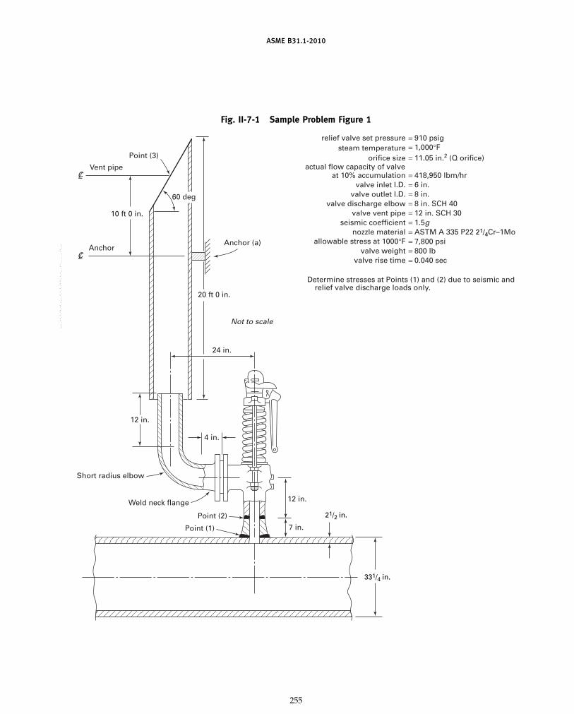
ASME B31.1-2010
Fig. II-7-1 Sample Problem Figure 1
Point (2)
Short radius elbow
12 in.
Weld neck flange 12 in.
7 in.Point (1)
20 ft 0 in.
24 in.
Not to scale
4 in.
10 ft 0 in.
Anchor (a)Anchor
Vent pipe
Point (3)
60 deg
21/2 in.
331/4 in.
= 910 psigrelief valve set pressuresteam temperature
orifice sizeactual flow capacity of valve
at 10% accumulationvalve inlet I.D.
valve outlet I.D.valve discharge elbow
valve vent pipeseismic coefficient
nozzle materialallowable stress at 1000°F
valve weightvalve rise time
Determine stresses at Points (1) and (2) due to seismic and relief valve discharge loads only.
= 418,950 lbm/hr= 6 in.= 8 in.
= 7,800 psi= 800 lb= 0.040 sec
= 8 in. SCH 40= 12 in. SCH 30
= ASTM A 335 P22 21/4Cr–1Mo= 1.5g
= 11.05 in.2 (Q orifice)= 1,000°F
255
Copyright ASME International Provided by IHS under license with ASME No reproduction or networking permitted without license from IHS
--`,,```````,,```,`,`,,,,`,`,`,`-`-`,,`,,`,`,,`---
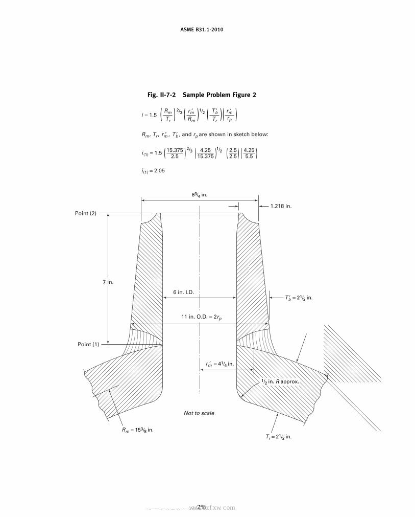
ASME B31.1-2010
Fig. II-7-2 Sample Problem Figure 2
7 in.
6 in. I.D.
1.218 in.
i(1) = 2.05
i(1) = 1.5
i = 1.5
11 in. O.D. = 2rp
Point (2)
Point (1)
Not to scale
= 21/2 in.
83/4 in.
2/3 1/2
2/3 1/2
Tr = 21/2 in.Rm = 153/8 in.
= 41/4 in.
1/2 in. R approx.
4.2515.375( )15.375
2.5( ) 4.255.5( )2.5
2.5( )
Rm
Rm, Tr , , , and rp are shown in sketch below:
Tr( ) r ′mr ′m
Rm( ) rp )T ′b
r ′m
T ′b
r ′m T ′b
Tr( ()
256
Copyright ASME International Provided by IHS under license with ASME No reproduction or networking permitted without license from IHS
--`,,```````,,```,`,`,,,,`,`,`,`-`-`,,`,,`,`,,`---标准分享网 www.bzfxw.com 免费下载

ASME B31.1-2010
For 8 in. SCH 40 short radius elbow,
LD
p 30
For 12 in. of 8 in. SCH 40 pipe,
LD
p12 in.
7.981 in.p 1.5
∑ �LD� p �Lmax
D � p 0.5 + 30 + 1.5 p 32.0
f p 0.013
k p 1.3
f �Lmax
D � p 0.416
From Chart II-1, P/P* p 1.647.
P1a p P1 (P/P*) p 194 psia
II-7.1.3 Reaction Force at Discharge Elbow Exit.Reaction force,
F1 pWV1
gc+ (P1 − Pa) A1
whereW p 116.38 lbm/secV1 p 2,116 ft/secgc p 32.2 lbm-ft/lbf-sec2
P1 p 118 psiaPa p 15 psiaA1 p 50.03 in.2
(P1 − Pa) p 118 − 15 p 103 psigWV1/gc p 7,648 lbf
(P1 − Pa) A1 p 5,153 lbfF1 p 12,801 lbf
II-7.1.4 Bending Moments at Points (1) and (2)(A) Bending Moment at Points (1) and (2) Due to Reaction
at Point (1)M1(1) p M1(2)
p F1 � L � DLFL p moment arm
p 24 in.DLF p dynamic load factor
To determine DLF, first determine the safety valve instal-lation period T:
T p 0.1846 �Wh3
EI
whereE p Young’s modulus of inlet pipe at design
temperaturep 23 � 106 psi
257
h p distance from run pipe to centerline of outletpiping
p 19 in.I p moment of inertia of inlet pipe
p 64
(Do4 − Di
4)
Use average O.D. and I.D. to determine I. Do p9.875 in. avg.; Di p 6 in. avg.
p 403.2 in.4
T p 0.00449 secW p weight of valve
p 800 lb
For a valve rise time of 0.040 sec p to, the ratio to/T is8.9. From Fig. II-3-2, DLF p 1.11.
Using F1 p 12,801 lbf, L p 24 in., and DLF p 1.11,
M1(1) p M1(2) p 341,018 in.-lb
(B) Bending Moments at Points (1) and (2) Due to SeismicLoadingSeismic force,
FS p mass � acceleration
p � 800 lbm
32.2 lbm-ft/lbf-sec2�� 1.5(32.2 ft/sec2)
p 1,200 lbf
Moment arm for Point (1) p 19 in.
MS(1) p 1,200 lbf (19 in.) p 22,800 in.-lb
Moment arm for Point (2) p 12 in.
MS(2) p 1,200 lbf (12 in.) p 14,400 in.-lb
(C) Combined Bending Moments at Points (1) and (2)
M(1) p M1(1) + MS(1) p 363,819 in.-lb
M(2) p M1(2) + MS(2) p 355,419 in.-lb
II-7.1.5 Stress Intensification Factors at Points (1)and (2)
(A) At Point (1), Branch Connection
i (1) p 2.05
(B) Stress Intensification Factors at Point (2), Butt Weld
i (2) p 1.0
Copyright ASME International Provided by IHS under license with ASME No reproduction or networking permitted without license from IHS
--`,,```````,,```,`,`,,,,`,`,`,`-`-`,,`,,`,`,,`---

ASME B31.1-2010
II-7.1.6 Predicted Stresses at Points (1) and (2)(A) Predicted Stresses at Point (1), Branch Connection
Predicted stress pPDo
4tn
Do
tnfor run pipe p
33.25 in.2.5 in.
p 13.3
Do
tnfor branch pipe p
11 in.2.5 in.
p 4.4
Use larger value with P p 910 psig.
Pressure stress(1) p 3,030 psi
Flexure stress(1) p0.75i M (1)
Z (1)
Z(1) p rb2 ts
tS p lesser of tr or (i) tb
tR p 2.5 in.; (i) tb p (2.05) 2.5 in.
tS p 2.5 in.
rb p 4.25 in.
Z(1) p 142 in.3
i(1) p 2.05; M(1) p 363,819 in.-lb
Flexure stress(1) p 3,939 psiCombined stress(1) p pressure stress(1)
+ flexure stress(1)
p 6,969 psi
(B) Predicted Stresses at Point (2), Butt Weld
Pressure stress pPDo
4tn
P p 910 psig
Do p 8.75 in.
tn p 1.218 in.
Pressure stress(2) p 1,635 psi
Flexure stress(2) p0.75 i M(2)
Z(2)
Z(2) p
32Do
4 − Di4
Do
Do p 8.75 in.
Di p 6 in.
Z(2) p 51.1 in.3
258
i(2) p 1.0
M(2) p 355,419 in.-lb
Flexure stress(2) p 6,955 psi
(Note that 0.75i is set equal to 1.0 whenever 0.75i is less than1.0, as in this case.)
Combined stress(2) p pressure stress(2)
+ flexure stress(2)
p 8,590 psi
(C) Comparison of Predicted Stress With Allowable Stress.Allowable stress of nozzle material at 1,000°F is
Sh p 7,800 psi
k p 1.2
kSh p 9,360 psi
Combined stress(1) p 6,969 psi
Combined stress(2) p 8,590 psi
II-7.1.7 Calculate the Maximum Operating Pressurefor Vent Pipe
P3 p P1 �A1
A3� p 118 psia � 50.03 in.2
114.80 in.2�p 51.4 psia
L/D for 20 ft 0 in. of 12 in. SCH 30 pipe p 19.85.
∑(L/D) p �Lmax
D � p 19.85
f p 0.013
k p 1.3
f �Lmax
D � p 0.258
From Chart II-1, P/P* p 1.506.
P2 p P3 (P/P*) p 77.4 psia
II-7.1.8 Check for Blowback From Vent Pipe. Calcu-late the velocity V2 that exists at the inlet to the ventpipe (para. II-2.2.1.4).
f �Lmax
D � p 0.258 from Step (7)
V3 p V1 p 2,116 ft/sec
From Chart II-1, V/V* p 0.7120.
V2 p V3 (V/V*) p 1,507 ft/sec
Copyright ASME International Provided by IHS under license with ASME No reproduction or networking permitted without license from IHS
--`,,```````,,```,`,`,,,,`,`,`,`-`-`,,`,,`,`,,`---
标准分享网 www.bzfxw.com 免费下载

ASME B31.1-2010
Check the inequality from para. II-2.3.1.2.
W (V1 − V2)gc
> (P2 − Pa) A2
− (P1 − Pa) A1
116.38 (2,116 − 1,507)32.2
> (77.4 − 14.7)(114.8)
− (118 − 14.7)(50.03)
2,201 > 2,030
The inequality has been satisfied but the designer mayrequire a design margin that would make 14 in. SCH 30more acceptable. If a larger vent pipe is chosen, thenthe vent pipe analysis would have to be repeated forthe 14 in. SCH 30 pipe.
II-7.1.9 Calculate Forces and Moments on Vent PipeAnchor
F2 pWV2
gc+ (P2 − Pa) A2
p(116.38)(1,507)
32.2
+ (77.4 − 14.7) (114.8)
p 5,447 + 7,198.0 p 12,645 lbf
F3 p(116.38)(2,116)
32.2
+ (51.4 − 14.7)(114.8)
p 7,648 + 4,213 p 11,861 lbf
Assume a 30 deg jet deflection angle for vent pipe outlet.Vertical component of F3
F3V p F3 cos 30 deg p 10,272 lbf
Horizontal component of F3
F3H p F3 sin 30 deg p 5,931 lbf
259
Fig. II-7-3 Sample Problem Figure 3
2,373 lb
Anchor (a)
60,568 lb-ft
Net imbalance on the vent pipe in the vertical direction is
F2 − F3V p 2,373 lbf
Moment on vent pipe anchor
∑M p (F2 − F3V)Do
2+ F3H � [distance from (a) to Point (3)]
p (2,373) �1.062 � + (5,931)(10.0)
p 60,568 ft-lb
The vent pipe anchor would then be designed for theloads shown in Fig. II-7-3 for safety valve operation.
II-7.1.10 Conclusion. Branch connection stresses atPoints (1) and (2) due to seismic and relief valve dis-charge are within 1.2 Sh. Blowback will not occur withthe 12 in. standard weight vent pipe. The vent pipeanchor loads have been identified.
Copyright ASME International Provided by IHS under license with ASME No reproduction or networking permitted without license from IHS
--`,,```````,,```,`,`,,,,`,`,`,`-`-`,,`,,`,`,,`---

ASME B31.1-2010
NONMANDATORY APPENDIX IIIRULES FOR NONMETALLIC PIPING AND PIPING LINED WITH
NONMETALS
FOREWORDASME B31.1 contains rules governing the design, fab-
rication, materials, erection, and examination of powerpiping systems. Experience in the application of nonme-tallic materials for piping systems has shown that anumber of considerations exist for the use of these mate-rials that are not addressed in the current body of theCode. To address these, the requirements and recom-mendations for the use of nonmetallic piping (except inparas. 105.3, 108.4, 116, and 118) have been separatelyassembled in this nonmandatory Appendix.
III-1 SCOPE AND DEFINITIONIII-1.1 General
III-1.1.1 This Appendix provides minimumrequirements for the design, materials, fabrication, erec-tion, testing, examination, and inspection of nonmetallicpiping and metallic piping lined with nonmetals withinthe jurisdiction of the ASME B31.1 Power Piping Code.All references to the Code or to Code paragraphs in thisAppendix are to the Section B31.1 Power Piping Code.In this Appendix, nonmetallic piping shall be limitedto plastic and elastomer based piping materials, with orwithout fabric or fibrous material added for pressurereinforcement. Metallic piping lined with nonmetalsshall be limited to factory-made plastic-lined ferrousmetal pipe, fittings, and flanges produced to one of theproduct standards for plastic-lined piping materialslisted in Table III-4.1.1.
III-1.1.2 Standards and specifications incorporatedin this Appendix are listed in Table III-4.1.1. The effectivedate of these documents shall correspond to the date ofthis Appendix.
III-1.1.3 The provisions in Chapters I through VIand in Appendices A through F are requirements of thisAppendix only when specifically referenced herein.
III-1.2 Scope
III-1.2.1 All applicable requirements of para. 100.1and the limitations of para. 105.3 shall be met in additionto those in this Appendix.
III-1.2.2 Use of this Appendix is limited to(A) water service.(B) nonflammable and nontoxic liquid, dry material,
and slurry systems.
260
(C) reinforced thermosetting resin pipe in buriedflammable and combustible liquid service systems [referto para. 122.7.3(F)].
(D) polyethylene pipe in buried flammable and com-bustible liquid and gas service. Refer to paras. 122.7.3(F)and 122.8.1(G).
(E) metallic piping lined with nonmetals. If used inaccordance with para. 122.9 for conveying corrosive liq-uids and gases, the design of the lined piping systemshall meet the requirements of para. 104.7.
III-1.2.3 Nonmetallic piping systems shall not beinstalled in a confined space where toxic gases could beproduced and accumulate, either from combustion ofthe piping materials or from exposure to flame or ele-vated temperatures from fire.III-1.3 Definitions and Abbreviations
III-1.3.1 Terms and definitions relating to plasticand other nonmetallic piping materials shall be in accor-dance with ASTM D 883. The following terms and defi-nitions are in addition to those provided in the ASTMstandard.adhesive: a material designed to join two other compo-nent materials together by surface attachment (bonding).adhesive joint: a bonded joint made using an adhesiveon the surfaces to be joined.bonder: one who performs a manual or semiautomaticbonding operation.bonding operator: one who operates a machine or auto-matic bonding equipment.bonding procedure: the detailed methods and practicesinvolved in the production of a bonded joint.Bonding Procedure Specification (BPS): the document thatlists the parameters to be used in the construction ofbonded joints in accordance with the requirements ofthis Code.butt-and-wrapped joint: a joint made by applying plies ofreinforcement saturated with resin to the surfaces to bejoined.chopped roving: a collection of noncontinuous glassstrands gathered without mechanical twist. Each strandis made up of glass filaments bonded together with afinish or size for application by chopper gun.chopped strand mat: a collection of randomly orientedglass fiber strands, chopped or swirled together with abinder in the form of a blanket.
Copyright ASME International Provided by IHS under license with ASME No reproduction or networking permitted without license from IHS
--`,,```````,,```,`,`,,,,`,`,`,`-`-`,,`,,`,`,,`---
标准分享网 www.bzfxw.com 免费下载

ASME B31.1-2010
continuous roving: a collection of continuous glassstrands wound into a cylindrical package withoutmechanical twist.
curing agent: a reactive material that when combinedwith a resin material reacts or polymerizes (crosslinks)with the resin; also referred to as a hardener.
diluent: a reactive modifying material, usually liquid,that reduces the concentration of a resin material tofacilitate handling characteristics and improve wetting.
electrofusion: a heat fusion joining process where the heatsource is an integral part of the fitting, such that whenelectric current is applied, heat is produced that meltsand joins the plastics.
fire retardant resin: a specially compounded materialcombined with a resin material designed to reduce oreliminate the tendency to burn.
flexibilizer: a modifying liquid material added to a resin-ous mixture designed to allow the finished componentthe ability to be flexed or less rigid and more prone tobending.
grout: a heavily filled paste material used to fill crevicesand transitions between piping components.
heat fusion joint: a joint made by heating the surfaces tobe joined and pressing them together so they fuse andbecome essentially one piece.
hot gas welded joint: a joint made by simultaneously heat-ing a filler material and the surfaces to be joined witha stream of hot air or hot inert gas until the materialssoften, after which the surfaces to be joined are pressedtogether and welded with the molten filler material.
liner: a coating or layer of material constructed as,applied to, or inserted within the inside surface of apiping component intended to protect the structure fromchemical attack, to inhibit erosion, or to prevent leakageunder strain.
seal weld: the addition of material external to a joint bywelding or bonding for the purpose of enhancing leaktightness.
solvent cement joint: a joint using a solvent cement tosoften the surfaces to be joined, after which the joiningsurfaces are pressed together and become essentiallyone piece as the solvent evaporates.
stiffness factor: the measurement of a pipe’s ability toresist deflection as determined in accordance withASTM D 2412.
thixatropic agent: a material added to resin to impart highstatic shear strength (viscosity) and low dynamic shearstrength.
ultraviolet absorber: a material that when combined in aresin mixture will selectively absorb ultravioletradiation.
woven roving: a heavy glass fiber fabric reinforcing mate-rial made by the weaving of glass fiber roving.
261
III-1.3.2 Abbreviations used in this Appendixdenote materials and terms as follows:
Abbreviation Term
ABS1 Acrylonitrile-butadiene-styreneAP PolyacetalCP Chlorinated polyetherCPVC1 Chlorinated poly (vinyl chloride)DS Design stressFEP1 Perfluoro (ethylene propylene)HDB Hydrostatic design basisHDS Hydrostatic design stressPA1 Polyamide (nylon)PB PolybutylenePE1 PolyethylenePFA Poly (perfluoroalkoxy)POP Poly (phenylene oxide)PP1 PolypropylenePPS PolyphenylenePR Pressure ratedPTFE1 PolytetrafluoroethylenePVC1 Poly (vinyl chloride)PVDC Poly (vinylidene chloride)PVDF Poly(vinylidene fluoride)RTR Reinforced thermosetting resinSDR Standard dimensional ratio
III-2 DESIGN
III-2.1 Conditions and Criteria
III-2.1.1 General(A) The Design Conditions of para. 101 shall apply
for the design of nonmetallic piping systems.(B) The design of nonmetallic piping systems must
ensure the adequacy of material and its manufacture,considering at least the following:
(B.1) tensile, compressive, flexural, shear strength,and modulus of elasticity at design temperature (long-term and short-term)
(B.2) creep characteristics for the service conditions(B.3) design stress and its basis(B.4) coefficient of thermal expansion(B.5) ductility and plasticity(B.6) impact and thermal shock properties(B.7) temperature limits for the service(B.8) transition temperatures: melting and
vaporization(B.9) toxicity of the material or of the gases pro-
duced by its combustion or exposure to elevatedtemperatures
(B.10) porosity and permeability(B.11) test methods(B.12) methods of making joints and their efficiency(B.13) deterioration in the service environment(B.14) the effects on unprotected piping from exter-
nal heat sources (particularly solar radiation)
1 Abbreviations in accordance with ASTM D 1600.
Copyright ASME International Provided by IHS under license with ASME No reproduction or networking permitted without license from IHS
--`,,```````,,```,`,`,,,,`,`,`,`-`-`,,`,,`,`,,`---

ASME B31.1-2010
III-2.1.2 Pressure–Temperature Ratings forComponents
(A) Components having specific pressure–temperature ratings have been established in the stan-dards listed in Table III-4.1.1. Other components maybe used in accordance with para. III-2.1.2(B).
(A.1) Except as qualified in para. III-2.1.3, the rat-ings of Tables III-4.2.1, III-4.2.2, and III-4.2.3 are the lim-iting values for allowable stresses at temperature in thisAppendix.
(A.2) The application of pressures exceeding thepressure–temperature ratings of valves is not permitted.Valves shall be selected for operation within the limitsdefined in para III-2.1.2(C).
(B) Components Not Having Specific Ratings(B.1) Pipe and other piping components for which
allowable stresses have been developed in accordancewith para. III-2.1.3, but that do not have specificpressure–temperature ratings, shall be rated by the rulesfor pressure design in para. III-2.2 within the range oftemperatures for which stresses are listed inTables III-4.2.1, III-4.2.2, and III-4.2.3.
(B.2) Custom-molded pipe and other piping com-ponents that do not have allowable stresses or pressure–temperature ratings shall be qualified for pressuredesign as required in para. III-2.2.9.
(B.3) When components other than describedabove, such as pipe or fittings not assigned pressure–temperature ratings in an ASME or American NationalStandard, are used, the manufacturer’s recommendedpressure–temperature rating shall not be exceeded.
(C) Allowances for Pressure and Temperature Variations(C.1) Nonmetallic Piping. Allowances for variations
of pressure, temperature, or both, above design condi-tions are not permitted. The most severe conditions ofcoincident pressure and temperature shall be used todetermine the design conditions.
(C.2) Metallic Piping Lined With Nonmetals. Allow-ances for pressure and temperature variations providedin para. 102.2.4 are permitted only if the suitability ofthe lining material for the increased conditions is estab-lished through prior successful experience or tests undercomparable conditions.
(D) Considerations for Local Conditions. Where two ser-vices that operate at different pressure–temperature con-ditions are connected, the valve segregating the twoservices shall be rated for the most severe service condi-tions. Other requirements of para. 102.2.5 must be con-sidered where applicable.
III-2.1.3 Allowable Stresses and Other Stress Limits(A) General. Tables III-4.2.1, III-4.2.2, and III-4.2.3 list
recommended maximum allowable stresses in the formof hydrostatic design stresses (HDS), allowable designstresses (DS), and the hydrostatic design basis (HDB),which may be used in design calculations except wheremodified by other provisions of this Appendix. The use
262
of hydrostatic design stresses for calculations other thanpressure design has not been established. The basis fordetermining allowable stresses and pressures is outlinedin para. III-2.1.3(B). The allowable stresses are groupedby materials and listed for stated temperatures. Wheresufficient data have been provided, straight-line interpo-lation between temperatures is permissible. Thematerials listed are available from one or more manufac-turers and may be obtained with maximum allowablestresses varying from those listed in Tables III-4.2.1,III-4.2.2, and III-4.2.3. These materials and values areacceptable for use where they have been established inaccordance with (B) below and para. III-2.2.9.
(B) Basis for Allowable Stresses for Internal Pressure(B.1) Thermoplastics. A method of determining
hydrostatic design stress (HDS) and pressure rating (PR)is described in ASTM D 2837. Hydrostatic designstresses are provided in Table III-4.2.1 for those materialsand temperatures for which sufficient data have beencompiled to substantiate a determination of stress. Dataon these materials at other temperatures, and on othermaterials, are being developed. Pending publication ofadditional data, the limitations in para. III-2.1.2(B) shallbe observed.
(B.2) Reinforced Thermosetting Resin (Laminated).For laminated piping components, the design stresses(DS) are listed in Table III-4.2.2. These typically are basedon one-tenth of the minimum tensile strengths specifiedin Table 1 of ASTM C 582.
(B.3) Reinforced Thermosetting Resin (Filament Woundand Centrifugally Cast). For filament wound and centrif-ugally cast piping components, hydrostatic design basis(HDB) values are listed in Table III-4.2.3. These valuesmay be obtained by procedures in ASTM D 2992. HDSmay be obtained by multiplying the HDB by a service(design) factor2 selected for the application, in accor-dance with procedures described in ASTM D 2992,within the following limits:
(B.3.1) When using the cyclic HDB fromTable III-4.2.3, the service (design) factor shall notexceed 1.0.
(B.3.2) When using the static HDB fromTable III-4.2.3, the service (design) factor shall notexceed 0.5.
III-2.1.4 Limits of Calculated Stresses Due toSustained Loads
(A) Internal Pressure Stresses. The limits for stress dueto internal pressure are provided in para. III-2.2.2.
(B) External Pressure Stresses. Stresses due to uniformexternal pressures shall be considered safe when thewall thickness of the component, and means of stiffen-ing, have been established in accordance withpara. III-2.2.9.
2 The service (design) factor should be selected by the designerafter evaluating fully the service conditions and the engineeringproperties of the specific material under consideration. Aside fromthe limits in paras. III-2.1.3(B.3.1) and (B.3.2), it is not the intentof the Code to specify service (design) factors.
Copyright ASME International Provided by IHS under license with ASME No reproduction or networking permitted without license from IHS
--`,,```````,,```,`,`,,,,`,`,`,`-`-`,,`,,`,`,,`---标准分享网 www.bzfxw.com 免费下载

ASME B31.1-2010
(C) External Loading Stresses. Design of reinforcedthermosetting resin (RTR) and thermoplastic pipingunder external loading shall be based on the results ofthe parallel plate loading test in ASTM D 2412. Theallowable deflection for RTR and thermoplastic pipeshall be 5% of the pipe diameter. Where other nonmetal-lic piping is intended for use under conditions of exter-nal loading, it shall be subject to a crushing or three-edge bearing test, in accordance with ASTM C 14 orC 301, and the allowable load shall be 25% of the mini-mum value obtained.
III-2.1.5 Limits of Calculated Stresses Due toOccasional Loads
(A) Operation. The total stress produced by pressure,live and dead loads, and by occasional loads, such aswind or earthquake, shall not exceed the considerationsand recommendations in para. III-2.5. Wind and earth-quake forces need not be considered as actingconcurrently.
(B) Test. Stresses due to test conditions are not subjectto the limitations in (A) above. It is not necessary toconsider other occasional loads, such as wind and earth-quake, as occurring concurrently with test loads.
III-2.1.6 Allowances(A) Erosion, Corrosion, Threading, and Grooving. In
determining the minimum required thickness of a pip-ing component, allowances shall be included for erosionand for thread depth or groove depth.
(B) Mechanical Strength. When necessary, pipe wallthicknesses shall be increased to prevent overstress,damage, collapse, or buckling due to superimposedloads from supports, ice formation, backfill, or othercauses. Where increasing thickness will cause excessivelocal stress, or is otherwise impractical, the requiredstrength may be obtained through the use of additionalsupports, braces, or other means without an increasedwall thickness. Particular consideration should be givento the mechanical strength of a small branch connectedto large piping or to equipment.
III-2.2 Pressure Design of Piping Components
III-2.2.1 Criteria for Pressure Design. The design ofpiping components shall consider the effects of pressureand temperature in accordance with para. III-2.1.2, andprovide for allowances in accordance with para. III-2.1.6.In addition, the design shall be checked for adequacyof mechanical strength under other applicable loadingsas required in paras. III-2.1.4 and III-2.1.5.
(A) The required minimum wall thickness of straightsections of pipe, tm, shall be determined in accordancewith eq. (1).
tm p t + c (1)
263
wherec p the sum of the mechanical allowances (thread
or groove depth), plus erosion and/or corrosionallowance, and the manufacturer’s minus toler-ance for product wall thickness, in. For threadedcomponents, the nominal thread depth shallapply. For machined surfaces or grooves wherea tolerance is not specified, the tolerance shallbe assumed to be 0.02 in., in addition to thespecified depth of the thread or groove.
t p pressure design thickness, in., as calculated inpara. III-2.2.2 for internal pressure, or in accor-dance with para. III-2.2.3 for external pressure
tm p minimum required thickness, in.
III-2.2.2 Straight Pipe Under Internal Pressure(A) The internal pressure design thickness, t, shall not
be less than that calculated by the following equations.(A.1) Thermoplastic Pipe
t pD
2Sa/P + 1(2)
(A.2) Reinforced Thermosetting Resin (Laminated)
t pD
2Sb/P + 1(3)
(A.3) Reinforced Thermosetting Resin (FilamentWound and Centrifugally Cast)
t pD
2ScF/P + 1(4)
whereD p outside diameter of pipe, in.F p service design factor in accordance with para.
III-2.1.3(B.3)P p internal design gage pressure, psi
Sa p hydrostatic design stress from Table III-4.2.1Sb p design stress from Table III-4.2.2Sc p hydrostatic design basis from Table III-4.2.3
(A.4) Metallic Pipe Lined With Nonmetals. Pressurelimitations shall be those established by the manufac-turer, considering both pressure and temperature limita-tions of the metal housings and sealing ability of theliner at flanged joints. In addition, the metallic pipe shallmeet the requirements of the mandatory sections of B31including the pressure design requirements ofASME B31.1 Chapter II.
(B) The internal pressure design thickness t in (A.1)and (A.2) above shall not include any thickness of pipewall reinforced with less than 30% (by weight) of rein-forcing fibers, or added liner thickness.
III-2.2.3 Straight Pipe Under External Pressure(A) Thermoplastic Pipe. The external pressure design
thickness t shall be qualified as required bypara. III-2.2.9.
Copyright ASME International Provided by IHS under license with ASME No reproduction or networking permitted without license from IHS
--`,,```````,,```,`,`,,,,`,`,`,`-`-`,,`,,`,`,,`---

ASME B31.1-2010
(B) Reinforced Thermosetting Resin Pipe(B.1) Above Ground. For determining design pres-
sure thickness for straight pipe under external pressure,the procedures outlined in ASTM D 2924 shall be fol-lowed. A safety factor of at least 4 shall be used.
(B.2) Below Ground. For determining design pres-sure thickness for straight pipe under external pressurein a buried condition, the procedures outlined inAWWA C-950, Appendix A, Sections A-2.5 and A-2.6shall be followed.
(C) Metallic Pipe Lined With Nonmetals(C.1) The external pressure design thickness for the
base (outer) material shall be determined in accordancewith para. 104.1.3.
(C.2) The external pressure design thickness, t, forthe lining material shall be qualified as required bypara. III-2.2.9.
III-2.2.4 Curved and Mitered Segments of Pipe(A) Pipe Bends. The minimum required thickness, tm,
of a pipe bend after bending shall be determined as forstraight pipe in accordance with para. III-2.2.1.
(B) Elbows. Manufactured elbows not in accordancewith para. III-2.1.2 shall meet the requirements ofpara. III-2.2.9.
(C) Mitered Bends. Mitered bend sections shall meetthe requirements of para. III-2.2.9.
III-2.2.5 Branch Connections(A) General. A pipe having a branch connection is
weakened by the opening that must be made in it, andunless the wall thickness of the pipe is sufficiently inexcess of that required to sustain the pressure, it is neces-sary to provide added reinforcement. The amount ofreinforcement required shall be in accordance with therequirements of para. III-2.2.9 except as provided in (B)and (C) below.
(B) Branch Connections Using Fittings. A branch con-nection shall be considered to have adequate strengthto sustain the internal and external pressure that willbe applied to it if a fitting (a tee, lateral, or cross) isutilized in accordance with para. III-2.1.2(A).
(C) Additional Considerations. The requirements of (A)and (B) above are designed to ensure satisfactory per-formance of a branch connection subjected only to inter-nal or external pressure. The designer shall also considerthe following:
(C.1) external forces and moments that may beapplied to a branch connection by thermal expansionand contraction, by dead and live loads, by vibration orpulsating pressure, or by movement of piping terminals,supports, and anchors
(C.2) adequate flexibility shall be provided inbranch piping to accommodate movements of the runpiping
(C.3) ribs, gussets, or clamps may be used for pres-sure-strengthening a branch connection in lieu of the
264
reinforcement required by (A) above if the adequacy ofthe design is established in accordance withpara. III-2.2.9
III-2.2.6 Closures. Closures in piping systems, suchas those provided for temporary or future lateral or end-point branches, shall be made using fittings, flanges, orparts in accordance with paras. III-2.2.7 and III-2.2.9.
III-2.2.7 Pressure Design of Flanges(A) General
(A.1) Nonmetallic flanges that are rated in accor-dance with published ASTM standards listed inTable III-4.1.1 shall be considered suitable for use withinthe limitations specified in this Appendix. Alternatively,flanges shall be in accordance with para. 103, or maybe designed in conformance with the requirements ofpara. III-2.2.7 or III-2.2.9.
(A.2) Flanges for use with ring type gaskets maybe designed in accordance with Section VIII, Division 1,Appendix 2 of the ASME Boiler and Pressure VesselCode, except that the allowable stresses for nonmetalliccomponents shall govern. All nomenclature shall be asdefined in the ASME Code except the following:
P p design gage pressureSa p bolt design stress at atmospheric temperature.
(Bolt design stresses shall not exceed those inAppendix A.)
Sb p bolt design stress at design temperature. (Boltdesign stresses shall not exceed those inAppendix A.)
Sf p allowable stress for flange material frompara. III-4.2
(A.3) The flange design rules in (A.2) above are notapplicable for designs employing full-face gaskets thatextend beyond the bolts or where flanges are in solidcontact beyond the bolts. The forces and reactions insuch a joint differ from those joints employing ring typegaskets, and the flanges should be designed in accor-dance with Section VIII, Division 1, Appendix Y of theASME Boiler and Pressure Vessel Code. (Note that theplastic flange sealing surface may be more irregular thanthe sealing surface of a steel flange. For this reason,thicker and softer gaskets may be required for plasticflanges.)
(B) Blind Flanges. Blind flanges shall be in accordancewith para. 103, or alternatively, may be designed inaccordance with para. 104.5.2, except that the allowablestress for nonmetallic components shall be taken fromthe data in para. III-4.2. Otherwise, the design of blindflanges shall meet the requirements of para. III-2.2.9.
III-2.2.8 Reducers. Reducers not in compliance withpara. 103 shall meet the requirements of para. III-2.2.9.
III-2.2.9 Design of Other Components(A) Listed Components. Other pressure-retaining com-
ponents manufactured in accordance with standards
Copyright ASME International Provided by IHS under license with ASME No reproduction or networking permitted without license from IHS
--`,,```````,,```,`,`,,,,`,`,`,`-`-`,,`,,`,`,,`---
标准分享网 www.bzfxw.com 免费下载
ASME B31.1-2010
listed in Table III-4.1.1 may be utilized in accordancewith para. III-2.1.2.
(B) Unlisted Components and Products. For pressure-retaining components and piping products not in accor-dance with the standards and specifications inTable III-4.1.1, and for proprietary components and jointsfor which the rules in paras. III-2.2.1 through III-2.2.8 donot apply, pressure design shall be based on calculationsconsistent with the design criteria of the Code. This mustbe substantiated by one or more of the following, withconsideration given to applicable dynamic effects, suchas vibration and cyclic operation, the effects of thermalexpansion or contraction, and the load effects of impactand thermal shock:
(B.1) extensive successful service experience undercomparable design conditions with similarly propor-tioned components or piping elements made of the sameor like material
(B.2) performance tests under design conditions,including applicable dynamic and creep effects, contin-ued for a time period sufficient to determine the accept-ability of the component or piping element for itsdesign life
(B.3) for either (B.1) or (B.2) above, reasonable inter-polations between sizes and pressure classes and reason-able analogies among related materials are permitted
III-2.3 Selection of Piping Components
III-2.3.1 General. Nonmetallic pipe, tubing, fittings,and miscellaneous items conforming to the standardsand specifications listed in Table III-4.1.1 shall be usedwithin the limitations of para. III-4 of this Appendix.
III-2.4 Selection of Piping Joints
III-2.4.1 General. Joints shall be suitable for thepressure–temperature design conditions and shall beselected giving consideration to joint tightness andmechanical strength under those conditions (includingexternal loadings), the materials of construction, thenature of the fluid service, and the limitations of paras.III-2.4.2 through III-2.4.7.
III-2.4.2 Bonded Joints(A) General Limitations. Unless limited elsewhere in
para. III-2.4.2, joints made by bonding in accordancewith para. III-5.1, and examined in accordance with para.III-6.2, may be used within other limitations on materialsand piping components in this Appendix.
(B) Specific Limitations(B.1) Fillet Joints. Fillet bonded joints may be used
in hot gas welded joints, only, if in conformance withthe requirements of para. III-5.1.3(A).
(B.2) Butt-and-Wrapped Joints. Butt-and-wrappedjoints in RTR piping shall be made with sufficientstrength to withstand pressure and external loadings.
265
III-2.4.3 Flanged Joints(A) General Limitations. Unless limited elsewhere in
para. III-2.4.3, flanged joints may be used, consideringthe requirements for materials in para. III-3, and forpiping components in para. III-2.3, within the followinglimitations:
(A.1) Joints With Flanges of Different Ratings. Whereflanges of different ratings are bolted together, the ratingof the joint shall be that of the lower rated flange. Boltingtorque shall be limited so that excessive loads will notbe imposed on the lower rated flange in obtaining atight joint.
(A.2) Metallic to Nonmetallic Flanged Joints. Wheremetallic and nonmetallic flanges are to be joined, bothshould be flat-faced. Full-faced gaskets are preferred. Iffull-faced gaskets are not used, bolting torque shall belimited so that the nonmetallic flange is not overloaded.
III-2.4.4 Expanded or Rolled Joints. Expanded orrolled joints are not permitted in nonmetallic pipingsystems.
III-2.4.5 Threaded Joints(A) General Limitations. Threaded joints may be used
within the requirements for materials in para. III-3, andon piping components in para. III-2.3, within the follow-ing limitations:
(A.1) Threaded joints shall be avoided in any ser-vice where severe erosion or cyclic loading may occur,unless the joint has been specifically designed for theseconditions.
(A.2) Where threaded joints are designed to be sealwelded, thread sealing compound shall not be used.
(A.3) Layout of piping should minimize reactionloads on threaded joints, giving special consideration tostresses due to thermal expansion and the operation ofvalves.
(A.4) Metallic-to-nonmetallic and dissimilar non-metallic threaded joints are not permitted in piping21⁄2 in. NPS and larger.
(A.5) Threaded joints are not permitted at designtemperatures above 150°F.
(B) Specific Limitations(B.1) Thermoplastic Resin Piping. Threaded joints in
thermoplastic piping shall conform to the followingrequirements:
(B.1.1) The pipe wall shall be at least Schedule80 thickness.
(B.1.2) Pipe threads shall conform toASME B1.20.1 NPT. Threaded fittings shall be compati-ble with that standard.
(B.1.3) A suitable thread lubricant and sealantshall be specified.
(B.1.4) Threaded piping joints are not permittedin polyolefin materials3 because of creep characteristicsthat must be considered.
3 The polyolefin group of materials includes polyethylene, poly-propylene, and polybutylene.
Copyright ASME International Provided by IHS under license with ASME No reproduction or networking permitted without license from IHS
--`,,```````,,```,`,`,,,,`,`,`,`-`-`,,`,,`,`,,`---

ASME B31.1-2010
(B.2) Thermosetting Resin Piping. Threaded joints inthermosetting resin piping shall conform to the follow-ing requirements:
(B.2.1) Threads shall be factory cut or molded onpipe ends and in matching fittings, with allowance forthread depth in accordance with para. III-2.2.1(A).
(B.2.2) Threading of plain ends of piping is notpermitted except where such male threads are limited tothe function of forming a mechanical lock with matchingfemale threads during bonding.
(B.2.3) Factory cut or molded threaded nipples,couplings, or adapters bonded to plain end components,may be used where necessary to provide connections tothreaded metallic piping.
III-2.4.6 Caulked Joints. In liquid service, bell andspigot and other caulked joints shall be used within thepressure–temperature limitations of the joints and thecomponents. Provisions shall be made to prevent disen-gagement of the joints at bends and dead ends and tosupport lateral reactions produced by branch connec-tions or other causes.
III-2.4.7 Proprietary Joints. Metal coupling,mechanical, gland and other proprietary joints may beused within the limitations on materials in para. III-3,on components in para. III-2.3, and the following:
(A) Adequate provisions shall be made to prevent theseparation of joints under internal pressure, tempera-ture, and external loads.
(B) Prior to acceptance for use, a prototype joint shallbe subjected to performance tests to determine the safetyof the joint under test conditions simulating all expectedfluid service conditions.
III-2.4.8 Metallic Piping Lined With Nonmetals(A) Welding is not permitted on lined components in
the field. Welding performed by the manufacturer toproduce pipe, fittings, and flanges to be used for jointsin elastomeric lined piping systems shall be performedso as to maintain the continuity of the lining and itsserviceability.
(B) Flared Linings(B.1) General. Flared ends of linings made in accor-
dance with the rules in para. III-5.5.2 may be used, sub-ject to material limitations.
(B.2) Specific Requirements. Flaring shall be limitedto applications that do not affect the serviceability ofthe lining.
III-2.5 Expansion and Flexibility
III-2.5.1 General Concepts(A) Elastic Behavior. The concept of piping strain
imposed by the restraint of thermal expansion or con-traction, and by external movements, applies in princi-ple to nonmetals. Nevertheless, the assumption that
266
stresses can be predicted from these strains in a nonme-tallic piping system, based on the linear elastic character-istics of the material, is generally not valid. The variationin elastic characteristics between otherwise similarmaterial types, between source manufacturers, andbetween batch lots of the same source material, can attimes be significant. If a method of flexibility analysisthat assumes elastic behavior is used, the designer mustbe able to demonstrate its validity for the system andmust establish conservative limits for the computedstresses.
(B) Overstrained Behavior. Stresses cannot be consid-ered proportional to displacement strains in nonmetallicpiping systems where an excessive level of strain maybe produced in a localized area of the system, and inwhich elastic behavior of the piping material is uncer-tain. (See unbalanced systems in para. 119.3 of the Code.)Overstrain must be minimized by effective system rout-ing to avoid the necessity of a requirement for specialjoints or expansion devices for accommodating exces-sive displacements.
(C) Progressive Failure. In thermoplastics and somethermosetting resins, displacement strains are not likelyto produce immediate failure of piping but may produceunacceptable distortion. Thermoplastics, particularly,are prone to progressive deformation that may occurupon repeated thermal cycling or under prolongedexposure to elevated temperature.
(D) Brittle Failure. In brittle thermosetting resins, thematerials are essentially rigid in behavior and mayreadily develop high-displacement stresses, to the pointof sudden breakage or fracture, under moderate levelsof strain.
III-2.5.2 Properties for Flexibility Analysis(A) Thermal Expansion Data. Table III-4.3.1 of this
Appendix lists coefficients of thermal expansion for sev-eral nonmetallic materials. More precise values in someinstances may be obtained from the manufacturers ofthese materials. If these values are to be used in stressanalysis, the thermal displacements shall be determinedas indicated in para. 119.
(B) Modulus of Elasticity. Table III-4.3.2 lists represen-tative data on the tensile modulus of elasticity, E, forseveral nonmetals. More precise values in someinstances may be obtained from the materials manufac-turer. (Note that the modulus may vary with the geomet-rical orientation of a test sample for filler-reinforced,filament-wound, or impregnated nonmetallic materi-als.) For materials and temperatures not listed, referto an authoritative source, such as publications of theNational Bureau of Standards.
(C) Poisson’s Ratio. For nonmetals, Poisson’s ratio willvary widely, depending upon materials and tempera-ture. For that reason, formulas used in linear elasticstress analysis can be used only if the manufacturer has
Copyright ASME International Provided by IHS under license with ASME No reproduction or networking permitted without license from IHS
--`,,```````,,```,`,`,,,,`,`,`,`-`-`,,`,,`,`,,`---
标准分享网 www.bzfxw.com 免费下载

ASME B31.1-2010
test data to substantiate the use of a specific Poisson’sratio for that application.
(D) Dimensions. The nominal thickness and outsidediameters of pipe and fittings shall be used in flexibilitycalculations.
(E) Metallic Pipe Lined With Nonmetals. Flexibility andstress analysis for metallic pipe lined with nonmetalsshall be in accordance with para. 119, except that anylimitations on allowable stresses or moments recom-mended by the manufacturers of the lined pipe shall beobserved.
III-2.5.3 Analysis(A) Formal stress analysis is not required for sys-
tems that(A.1) are duplicates, or replacements without sig-
nificant change, of successfully operating installations(A.2) can readily be judged adequate by compari-
son with previously analyzed systems(A.3) are routed with a conservative margin of
inherent flexibility, or employ joining methods or expan-sion joint devices, or a combination of these methods, inaccordance with applicable manufacturer’s instruction
(B) A substantiating stress analysis is required for asystem not meeting the above criteria. The designer maydemonstrate that adequate flexibility exists byemploying a simplified, approximate, or comprehensivestress analysis, using a method that can be shown to bevalid for the specific case. If essentially elastic behaviorcan be demonstrated for a piping system [see para.III-2.5.1(A)], the methods outlined in para. 119 may beapplicable.
(C) Special attention shall be given to movement(displacement or rotation) of the piping with respect tosupports and points of close clearance. Movements of arun at the junction of a small branch shall be consideredin determining the need for flexibility in the branch.
III-2.5.4 Flexibility(A) Piping systems shall have sufficient flexibility to
prevent the effects of thermal expansion or contraction,the movement of pipe supports or terminal points, orpressure elongation from causing
(A.1) failure of piping or supports from overstrainor fatigue
(A.2) leakage at joints(A.3) unacceptable stresses or distortion in the pip-
ing or in connected equipment(B) Where nonmetallic piping and components are
used, piping systems must be designed and routed sothat flexural stresses resulting from displacements due toexpansion, contraction and other causes are minimized.This concept requires special attention for supports andrestraints, the terminal connections, and for the tech-niques outlined in para. 119.5.1. Further informationon the design of thermoplastic piping can be found inPPI Technical Report TR-21.
267
(C) For metallic piping lined with nonmetals, thedesigner must consider the integrity of the lining indesigning for piping flexibility. This is a special consider-ation for linings less flexible than the metallic piping,such as glass or ceramics.
III-2.6 Design of Pipe Supporting Elements
III-2.6.1 General. In addition to the other applicablerequirements of paras. 120 and 121, supports, guides,and anchors shall be selected and applied to complywith the requirements of para. III-2.5, and the following:
(A) Support or restraint loads shall be transmitted topiping attachment or bearing points in a manner thatwill preclude pipe wall deformation or damage. Paddingor other isolation material should be installed in supportor restraint clearance spaces for added protection.
(B) Valves and in-line components shall be indepen-dently supported to prevent the imposition of high loadeffects on the piping or adjacent supports.
(C) Nonmetallic piping should be guarded wheresuch systems are exposed to casual damage from trafficor other work activities.
(D) A manufacturer’s recommendations for supportshall be considered.
III-2.6.2 Thermoplastic and RTR Piping. Supportsshall be spaced to avoid excessive displacement at designtemperature and within the design life of the pipingsystem. Decreases in the modulus of elasticity, withincreasing temperature, and creep of the material, withtime, shall be considered where applicable. The coeffi-cient of thermal expansion of most plastic materials ishigh and must be considered in the design and locationof supports and restraints.
III-2.7 Burial of RTR Pipe
III-2.7.1 Design. The design procedures ofANSI/AWWA C-950, Appendix A shall apply. A mini-mum pipe stiffness shall meet the requirements inTable 6 of ANSI/AWWA C-950. The minimum stiffness(F/�y) shall be determined at 5% deflection using theapparatus and procedures of ASTM D 2412.
III-2.7.2 Installation. The pipe manufacturer’s rec-ommendations shall be equal to or more stringent thanthose described in ASTM D 3839 for RTR pipe orASTM D 2774 for thermoplastic pipe. The manufactur-er’s recommendations should be followed.
III-3 MATERIALS
III-3.1 General Requirements
Paragraph III-3 provides limitations and qualifica-tions for materials based on their inherent properties.The use of these materials in piping may also be subjectto requirements and limitations in other parts of theCode.
Copyright ASME International Provided by IHS under license with ASME No reproduction or networking permitted without license from IHS
--`,,```````,,```,`,`,,,,`,`,`,`-`-`,,`,,`,`,,`---

ASME B31.1-2010
III-3.2 Materials and Specifications
III-3.2.1 Listed Materials. Listed materials used inpressure containing piping shall have basic allowablestresses and other design limits as covered inpara. III-2.1.
III-3.2.2 Unlisted Materials. Unlisted materials usedin pressure containing piping shall have basic allowablestresses and other design limits determined in accor-dance with para. III-2.1, or on a more conservative basis.
III-3.2.3 Unknown Materials. Materials of anunknown specification or standard shall not be used.
III-3.2.4 Reclaimed Materials. Reclaimed pipingcomponents may be used provided they are properlyidentified as conforming to a listed specification andotherwise meet the requirements of this Appendix. Suffi-cient cleaning and examination shall be performed todetermine that the components are acceptable for theintended service, considering at least the following:
(A) minimum available wall thickness(B) extent of any imperfections(C) possible loss of strength(D) chemical absorption
III-3.3 Temperature Limitations
The designer shall determine that materials whichmeet other requirements of this Appendix are suitablefor the fluid service throughout the operating tempera-ture range of the systems in which the materials willbe used.
III-3.3.1 Upper Temperature Limitations(A) The maximum design temperature for a listed
material shall not exceed maximum temperatures listedin Tables III-4.2.1, III-4.2.2, or III-4.2.3, as applicable,except as provided in para. III-2.1.3(A).
(B) An unlisted material acceptable under para.III-3.2.2 shall have upper temperature limits establishedin accordance with para. III-2.1.2.
III-3.3.2 Lower Temperature Limitations(A) The minimum design temperature for a listed
material shall not be lower than the minimum tempera-tures listed in Tables III-4.2.1 and III-4.2.2, as applicable,except as provided in para. III-2.1.3(A).
(B) An unlisted material acceptable under para.III-3.2.2 shall have lower temperature limits establishedin accordance with the manufacturer’s recommendationbut in no case less than −20°F.
III-3.4 Fluid Service Limitations
III-3.4.1 General Limitations. The use of nonmetallicpiping materials and components, under the scope ofthis Appendix, shall be limited to those services andconditions stated in para. III-1.2.2. In addition:
268
(A) Nonmetallic materials shall not be used undersevere cyclic conditions unless it can be demonstratedthat the materials are suitable for the intended servicein accordance with para. III-2.2.9.
(B) These materials shall be appropriately protectedagainst transient or operating temperatures and pres-sures beyond design limits, and shall be adequately pro-tected against mechanical damage.
(C) Limitations on the use or application of materialsin this Appendix apply to pressure containing parts.They do not apply to the use of materials for supports,linings, gaskets, or packing.
III-3.4.2 Specific Material Limitations(A) Thermoplastics shall be installed and protected
against elevated temperatures.(B) Thermosetting and fiber-reinforced thermosetting
resins shall be limited to the services stated inpara. III-1.2.2 and shall be installed and protectedagainst mechanical damage, vibration, and excessivecyclic strain in service.
III-3.4.3 Miscellaneous Materials: Joining andAuxiliary Materials. When selecting materials, such ascements, solvents, packing, and O-rings for making orsealing joints, the designer shall consider their suitabilityfor the fluid service.
III-3.5 Piping Component Requirements
III-3.5.1 Dimensions of Piping Components(A) Listed Piping Components. Dimensions of listed
piping components, including tolerances, shall conformto the applicable piping component specification or stan-dard listed in Table III-4.1.1.
(B) Unlisted Piping Components. Dimensions ofunlisted piping components, including tolerances, shallconform to those of comparable listed piping compo-nents insofar as practical. In all cases, dimensions shallbe such as to provide strength and performance equiva-lent to listed piping components and shall meet therequirements of para. III-2.2.9.
(C) Threads. Dimensions of piping connectionthreads not covered by a governing component specifi-cation or standard shall conform to para. III-2.4.5.
III-4 SPECIFICATIONS AND STANDARD DATA
III-4.1 Material Specifications and Standards
III-4.1.1 Standard Piping Components. Dimensionsof standard piping components shall comply with thestandards and specifications listed in Table III-4.1.1, inaccordance with the requirements of para. III-2.1.2(A).Abbreviations used in this Appendix and inTable III-4.1.1 are listed in para. III-1.3.2.
Copyright ASME International Provided by IHS under license with ASME No reproduction or networking permitted without license from IHS
--`,,```````,,```,`,`,,,,`,`,`,`-`-`,,`,,`,`,,`---
标准分享网 www.bzfxw.com 免费下载

ASME B31.1-2010
Table III-4.1.1 Nonmetallic Material and Product Standards
Standard or Specification Designation [Notes (1), (2)]
Nonmetallic Fittings
Threaded Poly(Vinyl Chloride) (PVC) Plastic Pipe Fittings, Schedule 80 ................................................................ ASTM D 2464-90Poly(Vinyl Chloride) PVC Plastic Pipe Fittings, Schedule 40 .................................................................................. ASTM D 2466-90aSocket-Type Poly(Vinyl Chloride) (PVC) Plastic Pipe Fittings, Schedule 80 ............................................................ ASTM D 2467-90Acrylonitrile-Butadiene-Styrene ABS Plastic Pipe Fittings, Schedule 40 ................................................................ ASTM D 2468-89Thermoplastic Gas Pressure Pipe, Tubing, and Fittings ......................................................................................... ASTM D 2513-90bReinforced Epoxy Resin Gas Pressure Pipe and Fittings ........................................................................................ ASTM D 2517-81 (R1987)Plastic Insert Fittings for Polyethylene (PE) Plastic Pipe ........................................................................................ ASTM D 2609-90Socket-Type Polyethylene Fittings for Outside Diameter-Controlled Polyethylene Pipe and Tubing ....................... ASTM D 2683-90Chlorinated Poly(Vinyl Chloride) CPVC Plastic Hot and Cold Water Distribution Systems ..................................... ASTM D 2846-90Butt Heat Fusion Polyethylene (PE) Plastic Fittings for Polyethylene (PE) Plastic Pipe and Tubing ....................... ASTM D 3261-90Polybutylene (PB) Plastic Hot-Cold-Water Distribution Systems ............................................................................ ASTM D 3309-89aReinforced Thermosetting Resin (RTR) Flanges ...................................................................................................... ASTM D 4024-87Threaded Chlorinated Poly(Vinyl Chloride) (CPVC) Plastic Pipe Fittings, Schedule 80 ........................................... ASTM F 437-89aSocket-Type Chlorinated Poly(Vinyl Chloride) (CPVC) Plastic Pipe Fittings, Schedule 40 ....................................... ASTM F 438-89aSocket-Type Chlorinated Poly(Vinyl Chloride) (CPVC) Plastic Pipe Fittings, Schedule 80 ....................................... ASTM F 439-89Electrofusion Type Polyethylene Fittings for Outside Diameter Controlled Polyethylene Pipe and Tubing ............ ASTM F 1055-98
Nonmetallic Pipe and Tube Products
Polyethylene Line Pipe .......................................................................................................................................... API 15LE (1987)Thermoplastic Line Pipe (PVC and CPVC) .............................................................................................................. API 15LP (1987)Low Pressure Fiberglass Line Pipe ........................................................................................................................ API 15LR (1986)Concrete Sewer, Storm Drain, and Culvert Pipe .................................................................................................... ASTM C 14-82Acrylonitrile-Butadiene-Styrene (ABS) Plastic Pipe, Schedules 40 and 80 ............................................................ ASTM D 1527-77 (1989)Poly(Vinyl Chloride) (PVC) Plastic Pipe, Schedules 40, 80 and 120 ..................................................................... ASTM D 1785-89Polyethylene (PE) Plastic Pipe, Schedule 40 ......................................................................................................... ASTM D 2104-89Polyethylene (PE) Plastic Pipe (SIDR-PR) Based on Controlled Inside Diameter .................................................... ASTM D 2239-89Poly(Vinyl Chloride) (PVC) Pressure-Rated Pipe (SDR Series) ................................................................................ ASTM D 2241-89Acrylonitrile-Butadiene-Styrene (ABS) Plastic Pipe (SDR-PR) ................................................................................. ASTM D 2282-89Machine-Made Reinforced Thermosetting-Resin Pipe ............................................................................................ ASTM D 2310-80 (1986)Polyethylene (PE) Plastic Pipe, Schedules 40 and 80, Based on Outside Diameter ............................................. ASTM D 2447-89Thermoplastic Gas Pressure Pipe, Tubing, and Fittings ......................................................................................... ASTM D 2513-86AReinforced Epoxy Resin Gas Pressure Pipe and Fittings ........................................................................................ ASTM D 2517-81 (R1987)Polybutylene (PB) Plastic Pipe (SIDR-PR) Based on Controlled Inside Diameter .................................................... ASTM D 2662-89Polybutylene (PB) Plastic Tubing ........................................................................................................................... ASTM D 2666-89Joints for IPS PVC Pipe Using Solvent Cement ...................................................................................................... ASTM D 2672-89Polyethylene (PE) Plastic Tubing ........................................................................................................................... ASTM D 2737-89Chlorinated Poly(Vinyl Chloride) (CPVC) Plastic Hot- and Cold-Water Distribution System .................................... ASTM D 2846-90Filament-Wound “Fiberglass” (Glass-Fiber Reinforced Thermosetting-Resin) Pipe ................................................. ASTM D 2996-88Centrifugally Cast Reinforced Thermosetting Resin Pipe ........................................................................................ ASTM D 2997-90Polybutylene (PB) Plastic Pipe (SDR-PR) Based on Outside Diameter ................................................................... ASTM D 3000-89Polyethylene (PE) Plastic Pipe (SDR-PR) Based on Controlled Outside Diameter .................................................. ASTM D 3035-89aPB Plastic Hot-Water Distribution Systems ............................................................................................................ ASTM D 3309-89aChlorinated Poly(Vinyl Chloride) (CPVC) Plastic Pipe, Schedules 40 and 80 ......................................................... ASTM F 441-89Chlorinated Poly(Vinyl Chloride) (CPVC) Plastic Pipe, (SDR-PR) ............................................................................. ASTM F 442-87Plastic-Lined Ferrous Metal Pipe, Fittings, and Flanges [Note (3)] ......................................................................... ASTM F 1545-97PVC Pressure Pipe, 4-inch through 12-inch, for Water .......................................................................................... *AWWA C 900-97AWWA Standard for Glass-Fiber-Reinforced Thermosetting-Resin Pressure Pipe ................................................... *AWWA C 950-88
Miscellaneous
Standard Methods of Testing Vitrified Clay Pipe ................................................................................................... ASTM C 301-87Contact-Molded Reinforced Thermosetting Plastic (RTP) Laminates for Corrosion Resistant Equipment ............... ASTM C 582-87Standard Definitions of Terms Relating to Plastics ................................................................................................ ASTM D 297-81Standard Abbreviations of Terms Relating to Plastics ........................................................................................... ASTM D 1600-90Threads 60° (Stub) for “Fiberglass” (Glass-Fiber-Reinforced Thermosetting-Resin) Pipe ....................................... *ASTM D 1694-91Solvent Cements for Acrylonitrile-Butadiene-Styrene (ABS) Plastic Pipe and Fittings ............................................ ASTM D 2235-88External Loading Properties of Plastic Pipe by Parallel-Plate Loading ................................................................... ASTM D 2412-87Solvent Cements for Poly(Vinyl Chloride) (PVC) Plastic Pipe and Fittings ............................................................. ASTM D 2564-88Heat-Joining Polyolefin Pipe and Fitting ................................................................................................................ ASTM D 2657-90
269
Copyright ASME International Provided by IHS under license with ASME No reproduction or networking permitted without license from IHS
--`,,```````,,```,`,`,,,,`,`,`,`-`-`,,`,,`,`,,`---
ASME B31.1-2010
Table III-4.1.1 Nonmetallic Material and Product Standards (Cont’d)
Standard or Specification Designation [Notes (1), (2)]
Miscellaneous (Cont’d)
Obtaining Hydrostatic Design Basis for Thermoplastic Pipe Materials .................................................................. ASTM D 2837-90Making Solvent-Cemented Joints With Poly (Vinyl Chloride) (PVC) Pipe and Fittings ............................................ ASTM D 2855-90Standard Test Method For External Pressure Resistance of Reinforced Thermosetting Resin Pipe ........................ ASTM D 2924-86Obtaining Hydrostatic or Pressure Design Basis for “Fiberglass” (Glass-Fiber-Reinforced Thermosetting-Resin)
Pipe and Fittings ............................................................................................................................................... *ASTM D 2992-87Joints for Plastic Pressure Pipes Using Flexible Elastomeric Seals ........................................................................ ASTM D 3139-89Underground Installation of “Fiberglass” (Glass-Fiber Reinforced Thermosetting Resin) Pipe ............................... ASTM D 3839-89Design and Construction of Nonmetallic Enveloped Gaskets for Corrosive Service .............................................. ASTM F 336-87Solvent Cements for Chlorinated Poly(Vinyl Chloride) (CPVC) Plastic Pipe and Fittings ........................................ ASTM F 493-89Electrofusion Joining Polyolefin Pipe and Fitting ................................................................................................... ASTM F 1290-98aPlastic Pipe Institute (PPI) Technical Report Thermal Expansion and Contraction of Plastic Pipe ......................... PPI TR-21-88
GENERAL NOTE: This standard contains no pressure-temperature ratings. Paragraph III-2.1.2(B.3) applies.
NOTES:(1) An asterisk (*) preceding the designation indicates that the standard has been approved as an American National Standard by the
American National Standards Institute.(2) Numbers in parentheses are reapproval dates.
III-4.1.2 Nonstandard Piping Components. Wherenonstandard piping components are designed in accor-dance with para. III-2.2, adherence to dimensional stan-dards of ANSI and ASME is strongly recommendedwhere practical.
III-4.1.3 Reference Documents(A) The documents listed in Table III-4.1.1 may con-
tain references to codes, standards, or specifications notlisted in the Table. Such unlisted codes, standards, orspecifications are to be used only in the context of thelisted documents in which they appear.
(B) Where documents listed in Table III-4.1.1 containdesign rules that are in conflict with this Appendix, thedesign rules of this Appendix shall govern.
(C) The fabrication, assembly, examination, inspec-tion, and testing requirements of paras. III-5 and III-6of this Appendix apply to the construction of pipingsystems. These requirements are not applicable to themanufacture of material or components listed inTable III-4.1.1, unless specifically stated.
III-4.2 Stress and Temperature Limits
Tables III-4.2.1, III-4.2.2, and III-4.2.3 provide listingsof the stress and recommended temperature limits forthe following, in accordance with paras. III-2.1.3(A)and (B).
III-4.2.1 Thermoplastic Piping Components.Table III-4.2.1 provides hydrostatic design stresses(HDS) and recommended temperature limits for ther-moplastic piping components.
III-4.2.2 Laminated Reinforced Thermosetting ResinPiping Components. Table III-4.2.2 provides designstresses (DS) and recommended temperature limits for
270
laminated reinforced thermosetting resin pipingcomponents.
III-4.2.3 Machine-Made Reinforced ThermosettingResin Pipe. Table III-4.2.3 provides hydrostatic designbases (HDB) at a temperature level of 73°F for machine-made reinforced thermosetting resin pipe.
III-4.2.4 Notes for Tables III-4.2.1, III-4.2.2, andIII-4.2.3. Notations may be identified in the body ofTables 4.2.1, 4.2.2, and 4.2.3 relative to the information,as applicable, in the Notes to those Tables.
III-4.3 Standard Data
The following data are available and are acceptablefor design purposes at the present time. It should benoted for all properties that individual compounds mayvary from the values shown. Manufacturers should beconsulted for specific values that may be applicable fortheir products.
III-4.3.1 See Table III-4.3.1, Thermal ExpansionCoefficients, Nonmetals.
III-4.3.2 See Table III-4.3.2, Modulus of Elasticity,Nonmetals.
III-5 FABRICATION, ASSEMBLY, AND ERECTION
III-5.1 Bonding Plastic Joints
III-5.1.1 General(A) Bonded joints that conform to para. III-5 may be
used in accordance with para. III-2.4.2.(B) Production joints shall be made only in accordance
with a written Bonding Procedure Specification (BPS)that has been qualified in accordance with para. III-5.1.2.
Copyright ASME International Provided by IHS under license with ASME No reproduction or networking permitted without license from IHS
--`,,```````,,```,`,`,,,,`,`,`,`-`-`,,`,,`,`,,`---
标准分享网 www.bzfxw.com 免费下载

ASME B31.1-2010
Table III-4.2.1 Hydrostatic Design Stresses (HDS) and Recommended Temperature Limits forThermoplastic Piping Components
RecommendedTemperature Limits[Notes (1), (2), (3)] Hydrostatic Design Stress at [Note (6)]
Minimum, Maximum, 73°F,ASTM °F °F ksi 100°F, 140°F, 180°F,
Spec. No. Material [Note (4)] [Note (5)] [Note (7)] ksi ksi ksi
D 2846 ⎫⎬F 441 CPVC4120 0 180 2.0 1.6 1.05 0.5⎭F 442
⎫D 2513 ⎬ PA32312 −20 180 1.25 1.1 0.8 0.63F 2145 ⎭
⎫D 2104⎪D 2239 ⎪ ⎧D 2447 PE2406 −30 140 0.63 0.54 0.4 . . .⎬ ⎨
D 2513 PE3408 −30 140 0.80 0.64 0.4 . . .⎩⎪D 2737 ⎪
⎭D 3035
. . . POP2125 30 210 . . . . . . . . . . . .[Note (8)]
. . . PP [Note (8)] 30 210 . . . . . . . . . . . .
⎧ PVC1120 0 100 2.0 1.2 . . . . . .⎫ ⎪D 1785 PVC1220 0 100 2.0 1.2 . . . . . .⎪ ⎪D 2241 PVC2110 0 100 1.0 0.6 . . . . . .⎬ ⎨
D 2513 PVC2112 0 100 1.25 0.8 . . . . . .⎪ ⎪D 2672 ⎭ ⎪ PVC2116 0 100 1.6 1.0 . . . . . .
⎩ PVC2120 0 100 2.0 1.2 . . . . . .
F 599 PVDC 0 175 . . . . . . . . . . . .[Note (8)]
F 491 PVDF 0 275 . . . . . . . . . . . .[Note (8)]
NOTES:(1) These recommended limits are for low pressure applications with water and other fluids that do not significantly affect the properties
of the thermoplastic material. In conservative practice, the upper temperature limits may be reduced at higher pressures dependingon the required service and expected life. Lower temperature limits are affected more by the environment, safeguarding, and installa-tion conditions than by strength.
(2) Because of low thermal conductivity, temperature gradients through the piping component wall may be substantial. Tabulated limitsapply where more than half the wall thickness is at or below the stated temperature.
(3) These recommended limits apply only to listed materials. Manufacturers should be consulted for temperature limits on specific typesand kinds of materials not listed.
(4) Minimum for installation.(5) Maximum for design.(6) The HDS listed is for water service only, reflecting a design factor of 0.5. For other services, refer to PPI TR-9 or the manufacturer for
recommended design factors.(7) Use these hydrostatic design stress values at all lower temperatures.(8) Nonpressure-boundary materials typically used as liners. No established HDS.
271
Copyright ASME International Provided by IHS under license with ASME No reproduction or networking permitted without license from IHS
--`,,```````,,```,`,`,,,,`,`,`,`-`-`,,`,,`,`,,`---
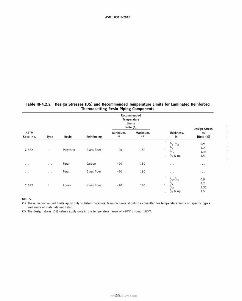
ASME B31.1-2010
Table III-4.2.2 Design Stresses (DS) and Recommended Temperature Limits for Laminated ReinforcedThermosetting Resin Piping Components
RecommendedTemperature
Limits[Note (1)] Design Stress,
ASTM Minimum, Maximum, Thickness, ksiSpec. No. Type Resin Reinforcing °F °F in. [Note (2)]
⎧ 1⁄8–3⁄16 0.9⎪ 1⁄4 1.2⎨C 582 I Polyester Glass fiber −20 180 5⁄16 1.35⎪⎩ 3⁄8 & up 1.5
. . . . . . Furan Carbon −20 180 . . . . . .
. . . . . . Furan Glass fiber −20 180 . . . . . .
⎧ 1⁄8–3⁄16 0.9⎪ 1⁄4 1.2⎨C 582 II Epoxy Glass fiber −20 180 5⁄16 1.35⎪⎩ 3⁄8 & up 1.5
NOTES:(1) These recommended limits apply only to listed materials. Manufacturers should be consulted for temperature limits on specific types
and kinds of materials not listed.(2) The design stress (DS) values apply only in the temperature range of −20°F through 180°F.
272
Copyright ASME International Provided by IHS under license with ASME No reproduction or networking permitted without license from IHS
--`,,```````,,```,`,`,,,,`,`,`,`-`-`,,`,,`,`,,`---
标准分享网 www.bzfxw.com 免费下载

ASME B31.1-2010
Table III-4.2.3 Hydrostatic Design Basis (HDB) for Machine-Made Reinforced Thermosetting Resin Pipe
HDB Stress [Note (1)] at73°F [Notes (2), (3)]
ASTM Material Cyclic, Static,Spec. No. and Designation ksi ksi
Type Grade Class ASTM D 2310 [Note (4)] [Note (5)]
⎧ Glass fiber No liner ⎧ RTRP-11AD 5.0 . . .⎨D 2517 filament wound ⎨ reinforced epoxy RTRP-11AW . . . 16.0⎩
⎩ resin
⎧No liner RTRP-11AD 5.0⎧ . . .⎨RTRP-11AW . . .⎩ 16.0⎪
⎨⎧ ⎪ ⎧Epoxy resin liner, RTRP-11FE 6.3Glass fiber . . .⎨⎨ ⎩ reinforced RTRP-11FD 5.0⎩reinforced epoxy . . .⎩ resin
D 2996 filament wound
⎧ Polyester resin liner,Glass fiber . . .⎧⎧ RTRP-12EC 4.0⎨ reinforced ⎪reinforced polyester . . .⎨ RTRP-12ED 5.0⎩ ⎪ ⎪resin 12.5RTRP-12EU . . .⎩⎨
⎪ . . .⎧ RTRP-12AD 5.0No liner ⎨ 12.5⎩ RTRP-12AU . . .⎩
⎧D 2997 centrifugally cast ⎧ Glass fiber Polyester resin liner, RTRP-22BT . . . 10.0⎧ ⎨⎨ reinforced polyester nonreinforced RTRP-22BU . . . 12.5⎩⎪⎩ resin ⎨⎪ ⎧Epoxy resin liner, RTRP-21CT . . . 10.0
⎨⎩ nonreinforced ⎩ RTRP-21CU . . . 12.5
NOTES:(1) A service (design) factor must be applied to these HDB values to obtain the HDS.(2) These HDB values apply only at 73°F.(3) Recommended temperature limits for these materials are shown in Table III-4.2.2.(4) When using the cyclic design basis, the service factor shall not exceed 1.0.(5) When using the static design basis, the service factor shall not exceed 0.5.
273
Copyright ASME International Provided by IHS under license with ASME No reproduction or networking permitted without license from IHS
--`,,```````,,```,`,`,,,,`,`,`,`-`-`,,`,,`,`,,`---

ASME B31.1-2010
Table III-4.3.1 Thermal Expansion Coefficients, Nonmetals
Mean Coefficients
Material Description 10−6 in./in./°F Range, °F 10−6 mm/mm/°C Range, °C
Thermoplastics
PVC, Type 1120 30 23–37 54 −5 to +3PVC, Type 2116 40 37–45 72 3−7CPVC 4120 34 . . . 61 . . .PE, Type 2406 90 . . . 162 . . .PE, Type 3408 90 70–120 162 21–49Polypropylene 43 . . . 77 . . .Poly(vinylidine chloride) 85 . . . 153 . . .Poly(vinylidine fluoride) 100 . . . 180 . . .
Reinforced Thermosetting Resins
Epoxy-glass, centrifugally cast 9–13 . . . 16–23.5 . . .Epoxy-glass, filament-wound 9–13 . . . 16–23.5 . . .Polyester-glass, centrifugally cast 9–15 . . . 16–27 . . .Polyester-glass, filament-wound 9–11 . . . 16–20 . . .Polyester-glass, hand lay-up 12–15 . . . 21.5–27 . . .
Other
Hard rubber (Buna N) 40 . . . 72 . . .
GENERAL NOTE: Values in this Table are representative. Values at actual design temperature shall be obtained from the manufacturers.
274
Copyright ASME International Provided by IHS under license with ASME No reproduction or networking permitted without license from IHS
--`,,```````,,```,`,`,,,,`,`,`,`-`-`,,`,,`,`,,`---
标准分享网 www.bzfxw.com 免费下载

ASME B31.1-2010
Table III-4.3.2 Modulus of Elasticity, Nonmetals
E, ksi (73.4°F) E, MPa (23°C)Material Description [Note (1)] [Note (1)]
Thermoplastics
PVC, Type 1120 420 2 895PVC, Type 2116 360 2 485CPVC 4120 420 2 895PE, Type 2406 90 620PE, Type 3408 110 740Polypropylene 120 825Poly(vinylidene/chloride) 100 690Poly(vinylidene fluoride) 194 1 340
Thermosetting Resins, Axially Reinforced
Epoxy-glass, centrifugally cast 1,200–1,900 8 725–13 100Epoxy-glass, filament-wound 1,100–2,000 7 585–13 790Polyester-glass, centrifugally cast 1,200–1,900 8 275–13 100Polyester-glass, filament-wound 1,000–2,000 6 895–13 790Polyester-glass, hand lay-up 800–1,000 5 515–6 895
Other
Hard rubber (Buna N) 300 2 070
NOTE:(1) The modulus of elasticity values for thermosetting resin pipe
are given in the longitudinal direction; different values mayapply in the circumferential or hoop direction. The modulus ofelasticity values for thermoplastic resin pipe are temperature-dependent and stress-time related. In all cases for materialslisted in this Table, manufacturers shall be consulted for spe-cific product information.
(C) Production joints shall be made only by qualifiedbonders or bonding operators who have satisfactorilypassed a performance qualification test that has beenperformed in accordance with a written BPS in accor-dance with para. III-5.1.2.
(D) Qualification in one BPS does not qualify abonder or bonding operator for any other bondingprocedure.
(E) Bonding materials that have deteriorated by expo-sure to air or prolonged storage or that will not spreadsmoothly shall not be used.
(F) Longitudinal joints are not within the scope ofpara. III-5.1.
(G) Joint Identification. Each qualified bonder andbonding operator shall be assigned an identificationsymbol. Unless otherwise specified in the engineeringdesign, each pressure containing bond or adjacent areashall be stenciled or otherwise suitably marked with theidentification symbol of the bonder or bonding operator.Identification stamping shall not be used and any mark-ing paint or ink shall not be detrimental to the pipingmaterial. In lieu of marking the bond, appropriate rec-ords shall be filed.
275
III-5.1.2 Qualification(A) Qualification of the BPS to be used, and of the
performance of bonders and bonding operators, isrequired. Bonding Procedure Specifications shall specify,for both the bonding operation and qualification testingrequirements, all required materials, including materialstorage requirements; the fixtures and tools required,including the care of tools; and the temperature require-ments for all operations, including the methods requiredfor temperature measurement.
(B) Bonding Responsibility. An employer of bondingpersonnel is responsible for the bonding done by mem-bers of his organization and, except as provided in (C)below, shall conduct the required performance qualifica-tion tests to qualify the bonding procedure specificationsand the bonders or bonding operators.
(C) Qualification by Others(C.1) Bonding Procedure Specification (BPS). The pip-
ing system erector shall be responsible for qualifying aBPS that personnel of his organization will use. Subjectto the specific approval of the designer, a BPS qualifiedby others may be used if the following conditions apply:
(C.1.1) The designer accepts that the proposedqualified BPS has been prepared and executed by aresponsible recognized organization with expertise inthe field of bonding.
(C.1.2) The designer accepts both the BPS andProcedure Qualification Record (PQR) by signature ashis own.
(C.1.3) The piping erector has at least one bonder,currently employed, who has satisfactorily passed a per-formance qualification test using the proposed quali-fied BPS.
(C.2) Bonding Performance Qualification. A pipingerector shall not accept a performance qualification testmade by a bonder or bonding operator for another pip-ing erector without the designer’s specific approval. Ifapproval is given, acceptance is limited to performancequalification tests on piping using the same or an equiva-lent BPS. The piping erector accepting such performancequalification tests shall obtain a copy of the PQR fromthe previous erector, showing the name of the pipingerector by whom bonders or bonding operators werequalified, the dates of such qualification, and the datethe bonder or bonding operator last assembled pressurepiping under the previous performance qualification.
(D) Qualification tests for the bonding procedure andoperator performance shall comply with the require-ments of the BPS and the following:
(D.1) A test assembly shall be fabricated in accor-dance with the bonding procedure specification. The testassembly shall consist of at least one pipe-to-pipe jointand one pipe-to-fitting joint. The size of the pipe usedfor the test assembly shall be as follows:
(D.1.1) When the largest size to be joined (withinthe BPS) is 4 in. NPS or smaller, the test assembly shallbe the same NPS as the largest size to be joined.
Copyright ASME International Provided by IHS under license with ASME No reproduction or networking permitted without license from IHS
--`,,```````,,```,`,`,,,,`,`,`,`-`-`,,`,,`,`,,`---

ASME B31.1-2010
(D.1.2) When the largest size to be joined withinthe BPS is greater than 4 in. NPS, the test assembly shallbe made of piping components either 4 in. NPS or aminimum of 25% of the NPS of the largest piping compo-nent to be joined, whichever is larger.
(D.2) The test assembly shall be subjected to oneof the following qualification test operations.
(D.2.1) When the test assembly has been cured,it shall be subjected to a hydrostatic pressure test of themaximum of either 150 psig or 1.5 times an equivalentallowable pressure that shall be calculated using theleast nominal wall thickness and outside diameter ofthe pipe in the test assembly. This pressure shall bedetermined using the equation in para. III-2.2.2(A) forthe test material. The test shall be conducted so that thejoint is loaded in both the circumferential and longitudi-nal directions. Joints shall not leak or separate whentested.
(D.2.2) When a test assembly is joined by heatfusion, the fusion joints may be tested by cutting a mini-mum of three coupons containing the joint and bendingthe strips using a procedure that shall be defined in theBPS. As a minimum requirement, the test strips shallnot break when bent a minimum of 90 deg, at ambienttemperature, over an inside bend radius of 1.5 times thenominal diameter of the tested pipe.
(E) Performance Requalification(E.1) Renewal of a bonding performance qualifica-
tion is required when(E.1.1) a bonder or bonding operator has not
used the specific bonding process for a period of timegreater than 6 months, or a specific maximum periodof time otherwise permitted in the BPS for the work
(E.1.2) there is a specific reason to question abonder or bonding operator’s ability to make bonds thatmeet the BPS
(E.2) Renewal of a bonding performance qualifica-tion for a specific bonding process may be made in onlya single test assembly.
(F) Qualification Records. An erector using bonders, orbonder operators, shall maintain a record of the proce-dures used and of operators employed by him who arequalified in these procedures.
III-5.1.3 Thermoplastic Joints(A) Solvent-Cemented Joints
(A.1) Preparation. PVC and CPVC surfaces to becemented shall be cleaned by wiping with a clean clothmoistened with acetone or methylethyl ketone. Cleaningfor ABS shall conform to ASTM D 2235. Cuts shall befree of burrs and circumferential cuts shall be as squareas those obtained by the use of a saw with a miter boxor a square-end sawing vise. A slight interference fitbetween the pipe and a fitting socket is preferred, andthe diametral clearance between a pipe and the entranceof a mating socket shall not exceed 0.04 in. This fit shallbe checked before solvent cementing.
276
Fig. III-5.1.3(A) Solvent-Cemented Joint
(A.2) Procedure. Joints shall be made in accordancewith a qualified BPS. ASTM D 2855 provides a suitablebasis for such a procedure. Solvent cements for PVC,CPVC, and ABS shall conform to ASTM D 2564, D 2846,and D 2235, respectively. Cement shall be applied to bothjoint surfaces. The amount of cement shall be sufficient toproduce a small continuous fillet of cement at the outerlimits of the joints. See Fig. III-5.1.3(A).
(A.3) Branch Connections. For branch connectionsnot using a tee, a manufactured full reinforcement saddlewith an integral branch socket shall be solvent cementedto the run pipe over its entire contact surface.
(A.4) Limitations on Imperfections. Imperfectionsexceeding the following limitations are considereddefects and shall be repaired and reexamined in accor-dance with para. III-5.1.5:
(A.4.A) protrusion of dried cement exceeding50% of pipe wall thickness into the bore of the pipe
(A.4.B) unfilled or unbonded areas in a joint asindicated by the lack or interruption of the continuousfillet noted in (A.2) above
(B) Heat Fusion Joints(B.1) Preparation. Surfaces to be heat fused together
shall be cleaned of any foreign material. Cuts shall befree of burrs, and circumferential cuts shall be as squareas those obtained by the use of a saw with a miter boxor a square-end sawing vise.
(B.2) Procedure. Joints shall be made in accordancewith a qualified BPS. The general procedures inASTM D 2657, Technique I-Socket Fusion, II-Butt Fusion,and III-Saddle Fusion provide a suitable basis for such aprocedure. Both surfaces to be joined shall be uniformlyheated to produce a continuous homogeneous bondbetween them. This will produce a small continuousfillet of fused material at the outer limits of the joints.See Fig. III-5.1.3(B).
(B.3) Branch Connections. Branch connections shallbe made only with the use of molded fittings in sizesthat are commercially available.
Copyright ASME International Provided by IHS under license with ASME
Not for Resale, 03/08/2011 00:55:16 MSTNo reproduction or networking permitted without license from IHS
--`,,```````,,```,`,`,,,,`,`,`,`-`-`,,`,,`,`,,`---
标准分享网 www.bzfxw.com 免费下载

ASME B31.1-2010
Fig. III-5.1.3(B) Heat Fusion Joints
Socket Joint Butt Joint
Fig. III-5.1.3(C) Thermoplastic Electrofusion Joints
SaddleButtCoupling
Coupling
Wire coils
Wire coils
Wire matt
Saddle tapping tee
(B.4) Limitations on Imperfections. Imperfectionsexceeding the following limitations are considereddefects and shall be repaired and reexamined in accor-dance with para. III-5.1.5:
(B.4.A) protrusion of fused material exceeding25% of the pipe wall thickness into the bore of the pipe
(B.4.B) unfilled or unbonded areas in a joint asindicated by the lack or interruption of the continuousfillet noted in (B.2) above
(C) Electrofusion Joints(C.1) Preparation. Surfaces to be heat fused together
shall be cleaned of all foreign material.(C.2) Procedure. Joints shall be made in accordance
with the qualified BPS. The general procedures inASTM F 1290, “Technique 1 — Coupling Procedure”
277
and “Technique 2 — Saddle Procedure,” provide a suit-able basis for the development of such a procedure. SeeFig. III-5.1.3(C).
III-5.1.4 Thermosetting Resin Joints(A) Preparation. Cutting of pipe and preparation of
bonding surfaces shall be done, as recommended by themanufacturer, without chipping or cracking of the cutends; particularly, the inner surface of centrifugally castpipe. Pipe may be preheated, if necessary, to complywith the above requirements. Cuts shall be free of burrs,and circumferential cuts shall be as square as requiredby the purchaser’s specifications or the recommenda-tions of the manufacturer, whichever requires the closersquareness. For branch connections, holes in the run
Copyright ASME International Provided by IHS under license with ASME No reproduction or networking permitted without license from IHS
--`,,```````,,```,`,`,,,,`,`,`,`-`-`,,`,,`,`,,`---
ASME B31.1-2010
pipe may be made with a hole saw. Mold release agentand any other material that may interfere with adhesionshall be removed from surfaces to be bonded.
(B) Joining Procedures(B.1) Socket and Spigot Joints. Joints shall be made
in accordance with a qualified BPS based on the manu-facturer ’s recommended procedure. Application ofadhesive to the surfaces to be joined, and assembly ofthose surfaces shall produce a continuous bond betweenthem. Cut ends of the pipe and edges of the laminatefabric shall be sealed to prevent fluid penetration of thepipe wall or the laminate material.
(B.2) Butt-and-Wrap Joints. Joints shall be made inaccordance with a qualified BPS. The general proceduresin ASTM C 582, Contact-Molded Reinforced Thermoset-ting Plastic (RTP) Laminates for Corrosion ResistantEquipment, provide a suitable basis for the developmentof such a procedure. Application of plies of reinforce-ment, saturated with catalyzed resin, to the surfaces tobe joined shall produce a continuous structure with thesurfaces. Cut ends shall be sealed as required in (B.1)above.
(C) Branch Connections. Branch connections shall bemade using a manufactured tee fitting or a full reinforce-ment saddle having suitable provisions for joining as in(B) above. The cut edges of any hole in the run pipeshall be sealed with adhesive at the time the saddle isbonded to the run pipe.
(D) Limitations on Imperfections. Imperfectionsexceeding the following limitations are considereddefects and shall be repaired and reexamined in accor-dance with para. III-5.1.5:
(D.1) protrusion of adhesive exceeding 25% of pipewall thickness into the bore at the bottom of a socket,or inside a branch connection
(D.2) unfilled or unbonded areas in the joint
III-5.1.5 Repair of Defects. Defective material, joints,and other workmanship in piping that fail to meet therequirements of paras. III-3 and III-5, and of the engi-neering design, shall be repaired or replaced. Limitationson imperfections, and the method and extent of therequired examination of repairs and replacements, shallbe the same as for the original work.
III-5.2 Bending
III-5.2.1 Pipe Bending. Flattening of a bend isdefined as the difference between the maximum andminimum outside diameters, at any cross section,expressed as a percentage of the nominal outside diame-ter. Flattening shall not exceed 8% for pipe exposedto internal pressure. For pipe under external pressure,flattening shall not exceed 3%. The thickness afterbending shall not be less than that required inpara. III-2.2.4(A).
278
III-5.2.2 Bending Methods. Pipe may be bent byany suitable hot or cold method permissible by radiilimitations and material characteristics of the pipe beingbent. Hot bending shall be done within a temperaturerange consistent with material characteristics, end-userequirements, and the pipe manufacturer ’srecommendations.
III-5.3 Component Forming
Piping components may be formed by any suitablehot or cold method permissible by the characteristics ofthe material being formed. Forming shall be done withina temperature range consistent with the material charac-teristics, end-use requirements, and the component man-ufacturer ’s recommendations. The thickness afterforming shall not be less than that required by the engi-neering design.
III-5.4 Assembly and Erection
III-5.4.1 General. The assembly and erection of non-metallic piping systems shall comply with the require-ments of para. 135 of the Code and para. III-5 of thisAppendix. In addition:
(A) When assembling nonmetallic flanges, flat wash-ers shall be used under all bolt heads and nuts. Thespecified maximum bolt torque shall not be exceeded.
(B) Full circumference wrenches shall be used totighten threaded pipe joints. Tools and other devicesused to hold or apply forces to the pipe shall be suchthat pipe surfaces are not scored or deeply scratched.For thermosetting resin piping, threads shall be coatedwith sufficient adhesive to cover the threads and com-pletely fill the clearance between the pipe and fittings.
III-5.5 Fabrication of Metallic Piping Lined WithNonmetals
III-5.5.1 Welding of Metallic Piping Lined WithNonmetals. Welding is not permitted on lined compo-nents in the field. Welding performed by the manufac-turer to produce pipe, fittings, and flanges to be usedin elastomeric lined piping systems shall conform to therequirements of ASME Section IX and shall be per-formed so as to maintain the continuity of the liningand its serviceability.
III-5.5.2 Flaring of Nonmetallic Linings(A) General. The provisions of this paragraph apply
to metallic pipe lined with plastic or other flexible mate-rial. To prevent the fluid from contacting the metallicpiping where the lining must be interrupted at a fieldinstalled flanged joint, the metal piping is trimmed sothat the end of the lining projects beyond the face of theflange. The projecting lining is then flared back so thatit covers a portion of the flange face, in a manner similarto a lap joint. When the flange is made up, the corres-ponding flared ends are pressed together, forming a seal.
Copyright ASME International Provided by IHS under license with ASME No reproduction or networking permitted without license from IHS
--`,,```````,,```,`,`,,,,`,`,`,`-`-`,,`,,`,`,,`---标准分享网 www.bzfxw.com 免费下载

ASME B31.1-2010
(A.1) Paragraph III-5.5.2 applies only to the flaringof linings in pipe that has previously been lined withnonmetals.
(A.2) Flaring that conforms to para. III-5.5.2 maybe used in accordance with para. III-2.4.8(B).
(A.3) Flaring shall be performed only in accordancewith a written flaring procedure specification, and onlyby qualified operators who have appropriate trainingor experience in the use of the applicable flaringprocedures.
III-6 EXAMINATION, INSPECTION, AND TESTING
III-6.1 General
The general requirements of Chapter VI with regardto visual examination and leak testing are basicallyapplicable to nonmetallic piping systems.
III-6.2 Examination and Inspection
III-6.2.1 Visual Examination(A) Visual examination is observation of the portion
of components, joints, and other piping elements thatare or can be exposed to view before, during, or aftermanufacture, fabrication, assembly, erection, inspection,or testing.
(B) Visual examination shall be performed in accor-dance with Article 9, Section V of the ASME Boiler andPressure Vessel Code.
III-6.2.2 Examination Required(A) Piping shall be examined at least to the extent
required herein, or to any greater extent specified in theengineering design.
(A.1) Visually examine at least 5% of fabrication.For bonds (joints) each bonder or bonding operator’swork shall be represented and shall include each typeof bond for each bonder or bonding operator.
(A.2) Visually examine 100% of fabrication forbonds, other than circumferential bonds, and other thanthose in components made to material specificationsrecognized in this Code.
279
(A.3) Perform a random visual examination of theassembly of threaded, bolted, and other joints to satisfythe inspector that these conform to the requirements ofpara. III-5.4.1.
(A.4) Perform a random visual examination duringerection of piping, including checking of alignment andsupports.
(A.5) Examine erected piping for evidence of dam-age that would require repair or replacement and forother deviations from the design.
(B) The inspector shall be assured, by examination ofcertifications, records, or other evidence that the materi-als and components are of the specified grades and thatthey have received the required examination and testing.
III-6.2.3 Extent of Required Examination. Whenvisual examination reveals a defect requiring repair:
(A) Two additional examinations of the same typeshall be made of the same kind of item (if of a bond,others by the same bonder or bonding operator).
(B) If the additional items examined as required by(A) above are acceptable, the item requiring repair shallbe replaced or repaired and reexamined to meet therequirements of the Code, and all items represented bythis additional examination shall be accepted.
(C) If either of the items examined as required by (A)above reveals a defect, two additional items shall beexamined.
(D) If the additional items examined as required by(C) above are acceptable, the items requiring repair shallbe replaced or repaired and reexamined to meet therequirements of the Code, and all items represented bythis additional examination shall be accepted.
(E) If either of the additional items examined asrequired by (C) above reveals a defect, all comparableitems shall be replaced or they shall be fully examined,and all items requiring repair shall be repaired and reex-amined to meet the requirements of the Code.
III-6.3 Pressure Tests
Leak tests, when specified, shall be performed inaccordance with para. 137.
Copyright ASME International Provided by IHS under license with ASME No reproduction or networking permitted without license from IHS
--`,,```````,,```,`,`,,,,`,`,`,`-`-`,,`,,`,`,,`---

ASME B31.1-2010
NONMANDATORY APPENDIX IVCORROSION CONTROL FOR ASME B31.1
POWER PIPING SYSTEMS
FOREWORD
Present Code rules apply to the design, materials,fabrication, erection, tests, and inspection of new pipingsystems normally termed “new construction.”
This nonmandatory Appendix contains guidelinesthat are applicable to existing operating piping systemscontained in the scope of ASME B31.1, as well as “newconstruction.”
Minimum requirements for corrosion control of powerpiping systems are outlined herein. It is recognized thatmany sound, although perhaps diverse, corrosion con-trol programs exist. The philosophy used has been toestablish minimum requirements. Users are encouragedto augment these guidelines to suit their particular needsand to offer constructive criticism to the Committee onthis Appendix.
IV-1 GENERAL
External and internal corrosion should be preventedor controlled consistent with design requirements andthe environment in which the system is located.
IV-1.1 Recommended Guidance
Application of corrosion control requires a significantamount of competent judgment. NACE1 RP-01-69,Recommended Practice-Control of External Corrosionon Underground or Submerged Metallic PipingSystems, and RP-01-75, Recommended Practice-Controlof Internal Corrosion in Steam Pipelines and PipingSystems, provide a guide for establishing the minimumrequirements for control of corrosion of underground orsubmerged metallic piping systems. In addition,ASME B31G, Manual for Determining the RemainingStrength of Corroded Pipelines [3] may provide addi-tional guidance.
IV-1.2 Protection of All Piping Systems
The following minimum requirements and proceduresshould be provided for protection of all piping systemscontaining hazardous liquids or gases and other pipingas specified by the owner against internal, external, andatmospheric corrosion.
1 NACE: National Association of Corrosion Engineers (NACEInternational), 1440 South Creek Drive, Houston, TX 77084-4906
280
IV-2 EXTERNAL CORROSION CONTROL FORBURIED OR SUBMERGED PIPELINES
IV-2.1 General
IV-2.1.1 Means to prevent or mitigate external cor-rosion of buried or submerged piping systems shouldbe considered in the initial design, unless it can be dem-onstrated by tests, investigations, or experience in thearea of installation that a detrimental corrosive environ-ment does not exist.
IV-2.1.2 A means for control of external corrosionof buried or submerged pipe and components may beaccomplished through application of an effective protec-tive coating or wrapping. This method of corrosion con-trol can be supplemented with cathodic protection suchas sacrificial anodes, rectifier-ground bed units, and suit-able drainage bonds in stray current areas. Materialsshould be selected with due regard to the type of supple-mental corrosion protection employed.
IV-2.2 Protective Coating
IV-2.2.1 Protective coatings applied for the pur-pose of external corrosion should
(A) be applied on a properly prepared surface(B) mitigate corrosion(C) have sufficient adhesion to the metal surface and
be free of voids so as to effectively resist underfilmmigration of moisture
(D) be sufficiently ductile to resist cracking(E) have sufficient strength to resist damage due to
handling and soil stress(F) be impact resistant
IV-2.2.2 Coatings should have low moistureabsorption characteristics and provide high electricalresistance. Properly compounded concrete coatings maybe used.
IV-2.2.3 Pipe coatings should be inspected visuallywith a holiday detector and thickness gage prior to back-filling the excavation. Any bare spots, thin areas, holi-days, or other damage to the coating should be repairedand reexamined prior to backfilling.
IV-2.2.4 Precautions should be taken to minimizepipe coating damage during installation if coated pipeis installed by boring, driving, or similar method.
Copyright ASME International Provided by IHS under license with ASME No reproduction or networking permitted without license from IHS
--`,,```````,,```,`,`,,,,`,`,`,`-`-`,,`,,`,`,,`---
标准分享网 www.bzfxw.com 免费下载

ASME B31.1-2010
IV-2.2.5 Pipe coatings should be protected fromdamage resulting from adverse ditch conditions or dam-age from supporting blocks. Only fine grain backfill ispermitted in contact with the coating. This fine grainlayer should be continuous and of sufficient thicknessto prevent coating damage from larger articles in thebackfill.
IV-2.2.6 The backfilling operation should be care-fully controlled to prevent damage to pipe coatings.
IV-2.3 Cathodic Protection System
IV-2.3.1 Unless it can be demonstrated by investi-gation, tests, or experience that cathodic protection isnot needed, a cathodic protection system should beinstalled for all new buried carbon steel, alloy, ductileiron, cast iron, aluminum, or other metallic piping.
IV-2.3.2 All cathodic protection systems shouldcomply with one or more of the criteria contained inSection 6 of the latest issue of the NACE StandardRP-01-69.
IV-2.3.3 Cathodic protection current should be con-trolled so as to prevent damage to the protective coating,pipe, or components.
IV-2.4 Electrical Isolation
IV-2.4.1 Buried or submerged coated and uncoatedpiping systems should be electrically isolated at all inter-connections with neighboring systems except wherearrangements are made for mutual cathodic protectionor where underground metallic structures are electri-cally interconnected and cathodically protected as a unit.Electrical isolation of dissimilar metals, i.e., steel pipeconnected to aluminum tanks, should be provided.
IV-2.4.2 Grounding of all piping systems, whererequired, should be in accordance with IEEE2
Standard 142 or acceptable alternate standards.
IV-2.4.3 The electrical continuity of all buried orsubmerged metallic piping systems is recommended forproper station grounding, and to facilitate the installa-tion of cathodic protection. Continuity across allmechanical joints should be achieved by electricalbonding.
IV-2.4.4 Where piping systems are located nearelectrical transmission tower footings, ground cables,ground rods, or in other areas where fault currents orunusual risk of lightning may be anticipated, pipingshould be provided with protection against damage thatmay result from fault currents or lightning. Protectivemeasures should also be taken at insulating deviceswhere used.
2 IEEE: Institute of Electrical and Electronics Engineers, 445 HoesLane, Piscataway, NJ 08854
281
IV-2.4.5 If a pipe culvert or sleeve is used, theencased pipe should be independently supported out-side each end of the sleeve and electrically insulatedthroughout the length of the section.
IV-2.5 Electrical Interference
IV-2.5.1 The possibility of external corrosioninduced by stray electrical currents in the earth is recog-nized. These stray currents are generated by sourcesindependent of the piping system, and are more pre-dominant in highly industrialized areas, mining regions,and locales containing high voltage, direct current, elec-trical power ground beds. Neighbor company pipelinecathodic protection systems are also a common sourceof stray earth currents.
IV-2.5.2 The protection of the piping systemagainst stray current induced corrosion should be pro-vided by metallic bonds, increased electrical cathodicprotection, supplemental protective coatings, or insulat-ing flanges.
IV-2.5.3 Each cathodic protection system providedfor the plant piping should be designed and installedso as to minimize any adverse effects on adjacent under-ground metallic structures.
IV-3 INTERNAL CORROSION CONTROL
IV-3.1 General
Internal corrosion might occur during operation. Aliquid or gas that will corrode the internal surfaces ofpiping should not be transported unless its corrosiveeffects have been investigated. The piping material andany lining should be selected to be compatible with theflowing fluid to minimize corrosion, in accordance withNACE Standard RP-01-75.
IV-3.2 Inhibitors
If inhibitors are used to control internal corrosion,sufficient coupon samples or other types of monitoringtechniques should be utilized to determine adequatelythe effectiveness of the inhibitors.
IV-3.3 Linings
If linings are used to prevent corrosion, they shouldmeet the quality specifications established by the designengineer. They should be inspected in accordance withindustry recommended practices. All base material andweld metal surfaces should be covered with the liningto at least the thickness specified by the designer.
IV-3.4 Precautions at Hydrotesting
Equipment fabricated from austenitic (300 series) andferritic (400 series) stainless steels and requiring hydro-static testing should be tested with deionized water,
Copyright ASME International Provided by IHS under license with ASME No reproduction or networking permitted without license from IHS
--`,,```````,,```,`,`,,,,`,`,`,`-`-`,,`,,`,`,,`---
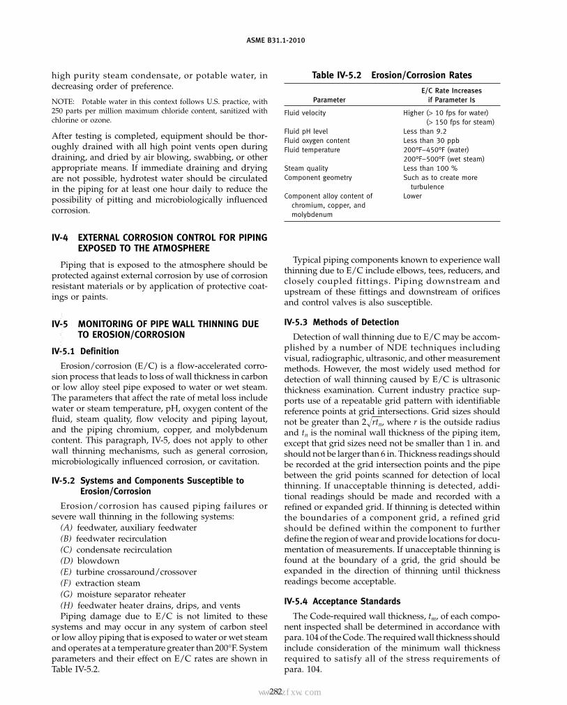
ASME B31.1-2010
high purity steam condensate, or potable water, indecreasing order of preference.
NOTE: Potable water in this context follows U.S. practice, with250 parts per million maximum chloride content, sanitized withchlorine or ozone.
After testing is completed, equipment should be thor-oughly drained with all high point vents open duringdraining, and dried by air blowing, swabbing, or otherappropriate means. If immediate draining and dryingare not possible, hydrotest water should be circulatedin the piping for at least one hour daily to reduce thepossibility of pitting and microbiologically influencedcorrosion.
IV-4 EXTERNAL CORROSION CONTROL FOR PIPINGEXPOSED TO THE ATMOSPHERE
Piping that is exposed to the atmosphere should beprotected against external corrosion by use of corrosionresistant materials or by application of protective coat-ings or paints.
IV-5 MONITORING OF PIPE WALL THINNING DUETO EROSION/CORROSION
IV-5.1 Definition
Erosion/corrosion (E/C) is a flow-accelerated corro-sion process that leads to loss of wall thickness in carbonor low alloy steel pipe exposed to water or wet steam.The parameters that affect the rate of metal loss includewater or steam temperature, pH, oxygen content of thefluid, steam quality, flow velocity and piping layout,and the piping chromium, copper, and molybdenumcontent. This paragraph, IV-5, does not apply to otherwall thinning mechanisms, such as general corrosion,microbiologically influenced corrosion, or cavitation.
IV-5.2 Systems and Components Susceptible toErosion/Corrosion
Erosion/corrosion has caused piping failures orsevere wall thinning in the following systems:
(A) feedwater, auxiliary feedwater(B) feedwater recirculation(C) condensate recirculation(D) blowdown(E) turbine crossaround/crossover(F) extraction steam(G) moisture separator reheater(H) feedwater heater drains, drips, and ventsPiping damage due to E/C is not limited to these
systems and may occur in any system of carbon steelor low alloy piping that is exposed to water or wet steamand operates at a temperature greater than 200°F. Systemparameters and their effect on E/C rates are shown inTable IV-5.2.
282
Table IV-5.2 Erosion/Corrosion Rates
E/C Rate IncreasesParameter if Parameter Is
Fluid velocity Higher (> 10 fps for water)(> 150 fps for steam)
Fluid pH level Less than 9.2Fluid oxygen content Less than 30 ppbFluid temperature 200°F–450°F (water)
200°F–500°F (wet steam)Steam quality Less than 100 %Component geometry Such as to create more
turbulenceComponent alloy content of Lower
chromium, copper, andmolybdenum
Typical piping components known to experience wallthinning due to E/C include elbows, tees, reducers, andclosely coupled fitt ings. Piping downstream andupstream of these fittings and downstream of orificesand control valves is also susceptible.
IV-5.3 Methods of Detection
Detection of wall thinning due to E/C may be accom-plished by a number of NDE techniques includingvisual, radiographic, ultrasonic, and other measurementmethods. However, the most widely used method fordetection of wall thinning caused by E/C is ultrasonicthickness examination. Current industry practice sup-ports use of a repeatable grid pattern with identifiablereference points at grid intersections. Grid sizes shouldnot be greater than 2�rtn, where r is the outside radiusand tn is the nominal wall thickness of the piping item,except that grid sizes need not be smaller than 1 in. andshould not be larger than 6 in. Thickness readings shouldbe recorded at the grid intersection points and the pipebetween the grid points scanned for detection of localthinning. If unacceptable thinning is detected, addi-tional readings should be made and recorded with arefined or expanded grid. If thinning is detected withinthe boundaries of a component grid, a refined gridshould be defined within the component to furtherdefine the region of wear and provide locations for docu-mentation of measurements. If unacceptable thinning isfound at the boundary of a grid, the grid should beexpanded in the direction of thinning until thicknessreadings become acceptable.
IV-5.4 Acceptance Standards
The Code-required wall thickness, tm, of each compo-nent inspected shall be determined in accordance withpara. 104 of the Code. The required wall thickness shouldinclude consideration of the minimum wall thicknessrequired to satisfy all of the stress requirements ofpara. 104.
Copyright ASME International Provided by IHS under license with ASME No reproduction or networking permitted without license from IHS
--`,,```````,,```,`,`,,,,`,`,`,`-`-`,,`,,`,`,,`---
标准分享网 www.bzfxw.com 免费下载

ASME B31.1-2010
A calculation of predicted wall thickness, tp, at thenext examination should be performed for all compo-nents with measured wall thickness less than 87.5% ofnominal wall thickness tn.
(A) All components with tp at the next examinationof less than tm or 70% tn, whichever is greater, should beidentified. Additional examinations during the currentinspection should be performed for
(A.1) equivalent piping items in other trains whenthe system containing the subject piping item consistsof more than one train.
(A.2) additional components in the same system/pipeline that have been determined to be susceptible toE/C.
When (1) and (2) above reveal additional componentsthat meet the criteria of (a)(1) above, this process shouldbe repeated until no additional components meet thecriteria.
(B) All components with predicted wall thickness atthe next examination of less than or equal to the greaterof tm or 0.3tn shall be repaired, replaced, or evaluatedfor acceptability for continued service. An acceptableevaluation procedure has been provided in [2] and [3]of para. IV-5.6.
283
IV-5.5 Repair/Replacement Procedures
Repair or replacement of piping components shouldbe performed in accordance with Appendix V. Erosionrates for chrome-molybdenum alloys are significantlylower than carbon steels and virtually nonexistent forstainless steels. When replacement is chosen, consider-ation of the increased resistance of alloy steels to E/Cshould be included in the selection of the replacementcomponent material. The use of backing rings, whichcan create areas of local turbulence that will promoteE/C damage, should be avoided.
IV-5.6 References
[1] ASME Code Case N-480, Approved May 1, 1990.[2] EPRI Report NP-5911M, “Acceptance Criteria for
Structural Evaluation of Erosion/Corrosion Thinning inCarbon Steel Piping,” July 1988.
[3] ASME B31G, Manual for Determining theRemaining Strength of Corroded Pipelines.
[4] NUREG-1344, “Erosion/Corrosion-Induced PipeWall Thinning in U. S. Nuclear Power Plants,” April 1989.
[5] EPRI Report NP-3944, “Erosion/Corrosion inNuclear Plant Steam Piping: Causes and InspectionProgram Guidelines,” April 1985.
Copyright ASME International Provided by IHS under license with ASME No reproduction or networking permitted without license from IHS
--`,,```````,,```,`,`,,,,`,`,`,`-`-`,,`,,`,`,,`---

(10)
ASME B31.1-2010
NONMANDATORY APPENDIX VRECOMMENDED PRACTICE FOR OPERATION, MAINTENANCE,
AND MODIFICATION OF POWER PIPING SYSTEMS
FOREWORD
The B31.1 Power Piping Code prescribes minimumrequirements for the construction of power and auxiliaryservice piping within the scope of para. 100.1. The Code,however, does not provide rules or other requirementsfor a determination of optimum system function, effec-tive plant operations, or other measures necessary toensure the useful life of piping systems. These concernsare the responsibility of the designer and, after construc-tion turnover, the Operating Company personnelresponsible for plant activities.
Past experience has shown that a need exists for thedefinition of acceptable plant practices for achievingboth reliable service and a predictable life in the opera-tion of power piping systems. This nonmandatoryAppendix is intended to serve that purpose. For thisobjective, Appendix V is structured in three parts thatrecognize and address the following basic concepts.
operation: the design of a piping system is based onspecified service requirements and operating limita-tions. Subsequent operation within these defined limitsis assumed and, for some systems, will be important foran acceptable service life.
maintenance: the design of a piping system assumes thatreasonable maintenance and plant service will be pro-vided. The lack of this support will, in some cases, intro-duce an increasing degree of piping system lifeuncertainty.
modifications: future modifications of a piping system orits operational functions are not assumed in originaldesign unless specified. Modifications must not invali-date the integrity of a piping system design.
The practices in Appendix V are recommended forall plants and systems within the scope of the PowerPiping Code, both for new construction and for existingplants in operation. An acceptable implementation ofthese or equivalent practices will be beneficial for newsystems. The application of these practices is recom-mended for power piping systems in operating plants.
The recommended practices in this Appendix defineminimum requirements for establishing a program toaccommodate the basic considerations for piping systemoperation, maintenance, service, modification, and com-ponent replacement.
284
A record-keeping program is prescribed that can serveas a point of reference for analyzing piping system dis-tortions or potential failures. Such a program is intendedto identify distortions or failures and assure compatibil-ity between the materials and components of existingpiping systems with those portions undergoing repair,replacement, or modification.
V-1 DEFINITIONS1
Code: ASME Code for Pressure Piping, ASME B31.1Power Piping.
component: equipment, such as vessel, piping, pump, orvalve, which are combined with other components toform a system.
critical piping systems: those piping systems that are partof the feedwater-steam circuit of a steam generatingpower plant, and all systems which operate under two-phase flow conditions. Critical piping systems includeruns of piping and their supports, restraints, and rootvalves. Hazardous gases and liquids, at all pressure andtemperature conditions, are also included herein. TheOperating Company may, in its judgment, considerother piping systems as being critical in which case itmay consider them as part of this definition.
examination: an element of inspection consisting of inves-tigation of materials, components, supplies, or servicesto determine conformance to those specified require-ments which can be determined by such investigation.Examination is usually nondestructive and includessimple physical manipulation, gaging, andmeasurement.
failure: physical condition that renders a system, compo-nent, or support inoperable.
maintenance: actions required to assure reliable and con-tinued operation of a power plant, including care, repair,and replacement of installed systems.
modification: change in piping design or operation andaccomplished in accordance with the requirements andlimitations of the Code.
procedure: document that specifies or describes how anactivity is to be performed. It may include methods to
1 The definitions pertain specifically to this Appendix.
Copyright ASME International Provided by IHS under license with ASME No reproduction or networking permitted without license from IHS
--`,,```````,,```,`,`,,,,`,`,`,`-`-`,,`,,`,`,,`---
标准分享网 www.bzfxw.com 免费下载
ASME B31.1-2010
be employed, equipment or materials to be used, andsequences of operations.
qualification (personnel): demonstration of the abilitiesgained through training and/or experience that enablean individual to perform a required function.
renewal: activity that discards an existing component andreplaces it with new or existing spare materials of thesame or better qualities as the original component.
repair: to restore the system or component to its designedoperating condition as necessary to meet all Coderequirements.
specification: a set of requirements to be satisfied by aproduct, material, or process, indicating, wheneverappropriate, the procedure by means of which it maybe determined whether the requirements given aresatisfied.
V-2 GENERAL
V-2.1 Application
V-2.1.1 This Appendix recommends minimumrequirements for programs to operate and maintainASME B31.1 Power Piping systems and also for therepairs to these systems.
V-2.1.2 Local conditions and the location of pipingsystems (such as indoors, outdoors, in trenches, or bur-ied) will have considerable bearing on the approach toany particular operating and maintenance procedure.Accordingly, the methods and procedures set forthherein serve as a general guide. The Operating Companyis responsible for the inspection, testing, operation, andmaintenance of the piping system and shall have theresponsibility for taking prudent action to deal withinherent plant conditions.
V-2.2 Conformance
V-2.2.1 When conformance with time periods forexamination recommended in this document is imprac-tical, an extension may be taken if an evaluation demon-strates that no safety hazard is present.
V-2.3 Requirements
V-2.3.1 This Appendix recommends that the fol-lowing listed items be established and implemented:
(A) complete design and installation records of the“as built” large bore piping systems, including expan-sion joints, hangers, restraints, and other supportingcomponents. The Operating Company shall define thosesizes considered to be large bore pipe.
(B) records of operation and maintenance history.(C) programs for periodic inspection and monitoring.(D) procedures for reporting and analyzing failures.(E) procedures for maintenance, repairs, and
replacements.
285
(F) procedures for abandoning piping systems andfor maintaining piping systems in and out-of-servicecondition.
(G) procedures for assuring that all personnelengaged in direct maintenance of such piping systemsas defined in para. V-5.2.1(C) are qualified by trainingor experience for their tasks or work.
V-3 OPERATING AND MAINTENANCE PROGRAM
V-3.1 General
Each Operating Company shall develop an operatingand maintenance program comprising a series of writtenprocedures, keeping in mind that it is not possible toprescribe a single set of detailed operating and mainte-nance procedures applicable to all piping systems. Theoperating and maintenance procedures shall includepersonnel qualifications as defined by the OperatingCompany, material history and records, and supplemen-tary plans to be implemented in case of piping systemfailures.
V-3.2 Documentation
Each plant should maintain and file the followingdocumentation that exists for each unit:
(A) current piping drawings(B) construction isometrics (or other drawings) that
identify weld locations(C) pipeline specifications covering material, outside
diameter, and wall thickness(D) flow diagrams(E) support drawings(F) support setting charts(G) records of any piping system modifications(H) material certification records(I) records of operating events that exceed design cri-
teria of the piping or supports(J) valve data(K) allowable reactions at piping connections to
equipment(L) welding procedures and records
V-4 REQUIREMENTS OF THE OPERATING,MAINTENANCE, AND MODIFICATIONPROCEDURES
The Operating Company shall have procedures forthe following:
(A) to perform normal operating and maintenancework. These procedures shall include sufficientlydetailed instructions for employees engaged inoperating and maintaining the piping systems.
(B) to prescribe action required in the event of a pip-ing system failure or malfunction that may jeopardizepersonnel safety, safe operation, or system shutdown.Procedures shall consider
Copyright ASME International Provided by IHS under license with ASME No reproduction or networking permitted without license from IHS
--`,,```````,,```,`,`,,,,`,`,`,`-`-`,,`,,`,`,,`---
ASME B31.1-2010
(B.1) requirements defined for piping system oper-ations and maintenance and should include failure con-ditions under which shutdown may be required.Procedures should include both the action required andthe consequence of the action on related systems orsubsystems.
(B.2) the designation of personnel responsible forthe implementation of required action, and minimumrequirements for the instruction, training, and qualifica-tion of these personnel.
(C) to inspect and review changes periodically in con-ditions affecting the safety of the piping system. Theseprocedures shall provide for a system of reporting to adesignated responsible person in order that correctivemeasures may be taken.
(D) to ensure that modifications are designed andimplemented by qualified personnel and in accordancewith the provisions of the Code.
(E) to analyze failures to determine the cause anddevelop corrective action to minimize the probability ofrecurrence.
(F) to intentionally abandon unneeded piping sys-tems, or portions thereof, and to maintain those that areout of service for extended periods of time as definedby the Operating Company.
(G) to ensure that instruction books and manuals areconsulted in performing maintenance operations.
(H) to log, file, maintain, and update instructionbooks.
(I) to log operating and maintenance records.(J) to review and revise procedures periodically as
dictated by experience and changes in conditions.
V-5 PIPING AND PIPE SUPPORT MAINTENANCEPROGRAM AND PERSONNEL REQUIREMENTS
V-5.1 Maintenance Program
V-5.1.1 The maintenance program shall includethe following listed features:
(A) a purpose for the program(B) the frequency for performing all elements of main-
tenance and inspection listed in the program(C) generic requirements as related to initial hanger
positions at time of unit startup, changes and adjust-ments in hanger positions at periodic inspections, andreview of manufacturer’s instruction and maintenancemanuals applicable to components included in theprogram
(D) updating and modification as may be desirableby reason of Code revisions and technological advancesor other considerations
(E) steps to keep maintenance and inspection person-nel aware of program revisions
286
V-5.2 Personnel
V-5.2.1 To the extent necessary for conformancewith the maintenance program of the OperatingCompany, only qualified and trained personnel shall beutilized for the following:
(A) observation, measurement, and recording theposition of piping systems and hanger readings
(B) adjustment of hangers and all other componentsof support and restraint systems
(C) repair and periodic maintenance routines includ-ing, but not limited to
(C.1) routine piping assembly, including weldingof integral attachments
(C.2) mechanical repair of valves, traps, and similartypes of piping specialty components, includingpackings
(C.3) removal and replacement of piping insulation(C.4) lubrication of applicable piping and hanger
components, such as valves and constant supports,maintenance of fluid levels in hydraulic restraints; andstroking of hydraulic and mechanical dynamic restraints(snubbers)
(C.5) routine surveillance for changing conditionsincluding changes in position of piping and settings ofpiping hangers and shock suppressors (snubbers)
V-5.2.2 Review of records and failure reports anddecisions concerning corrective actions or repairs shouldbe carried out by or under the direction of a qualifiedpiping engineer.
V-5.2.3 Welding and Heat Treatment Personnel(A) Welders shall be qualified to approved welding
procedures. Qualification of weld procedures and thequalification performance of the welder shall be inaccord with the requirements of para. 127.5.
(B) Trained personnel shall perform preheat and post-heat treatment operations as described in the require-ments of para. 131.
V-5.2.4 Examination, Inspection, and Testing Person-nel. Trained personnel shall perform nondestructiveexaminations (NDE), including visual inspections andleak tests (LT), all in accord with the requirements ofpara. 136.
V-6 MATERIAL HISTORY
V-6.1 Records
V-6.1.1 Records shall be maintained to the extentnecessary to permit a meaningful failure analysis orreconstruction of a prior condition should the need arise.These records may be limited to those systems identifiedas critical as defined herein.
Copyright ASME International Provided by IHS under license with ASME No reproduction or networking permitted without license from IHS
--`,,```````,,```,`,`,,,,`,`,`,`-`-`,,`,,`,`,,`---
标准分享网 www.bzfxw.com 免费下载
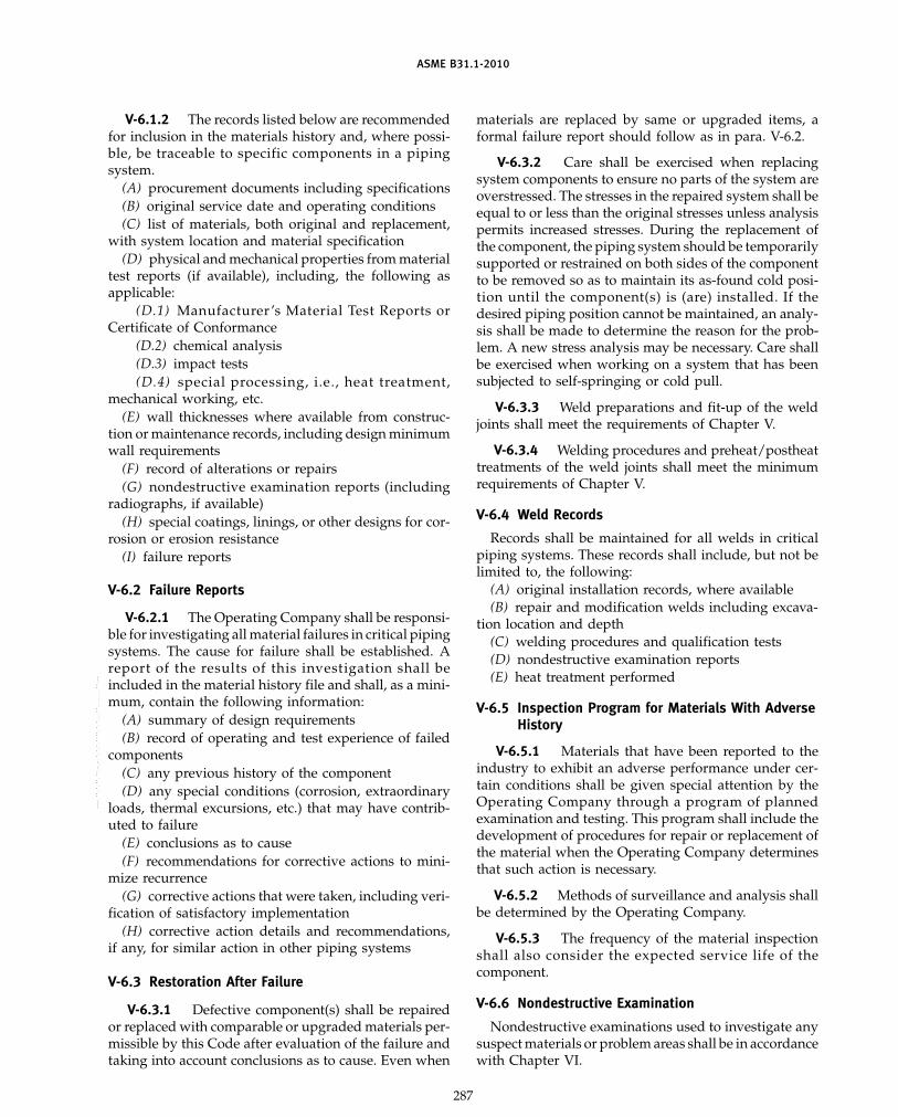
ASME B31.1-2010
V-6.1.2 The records listed below are recommendedfor inclusion in the materials history and, where possi-ble, be traceable to specific components in a pipingsystem.
(A) procurement documents including specifications(B) original service date and operating conditions(C) list of materials, both original and replacement,
with system location and material specification(D) physical and mechanical properties from material
test reports (if available), including, the following asapplicable:
(D.1) Manufacturer ’s Material Test Reports orCertificate of Conformance
(D.2) chemical analysis(D.3) impact tests(D.4) special processing, i.e., heat treatment,
mechanical working, etc.(E) wall thicknesses where available from construc-
tion or maintenance records, including design minimumwall requirements
(F) record of alterations or repairs(G) nondestructive examination reports (including
radiographs, if available)(H) special coatings, linings, or other designs for cor-
rosion or erosion resistance(I) failure reports
V-6.2 Failure Reports
V-6.2.1 The Operating Company shall be responsi-ble for investigating all material failures in critical pipingsystems. The cause for failure shall be established. Areport of the results of this investigation shall beincluded in the material history file and shall, as a mini-mum, contain the following information:
(A) summary of design requirements(B) record of operating and test experience of failed
components(C) any previous history of the component(D) any special conditions (corrosion, extraordinary
loads, thermal excursions, etc.) that may have contrib-uted to failure
(E) conclusions as to cause(F) recommendations for corrective actions to mini-
mize recurrence(G) corrective actions that were taken, including veri-
fication of satisfactory implementation(H) corrective action details and recommendations,
if any, for similar action in other piping systems
V-6.3 Restoration After Failure
V-6.3.1 Defective component(s) shall be repairedor replaced with comparable or upgraded materials per-missible by this Code after evaluation of the failure andtaking into account conclusions as to cause. Even when
287
materials are replaced by same or upgraded items, aformal failure report should follow as in para. V-6.2.
V-6.3.2 Care shall be exercised when replacingsystem components to ensure no parts of the system areoverstressed. The stresses in the repaired system shall beequal to or less than the original stresses unless analysispermits increased stresses. During the replacement ofthe component, the piping system should be temporarilysupported or restrained on both sides of the componentto be removed so as to maintain its as-found cold posi-tion until the component(s) is (are) installed. If thedesired piping position cannot be maintained, an analy-sis shall be made to determine the reason for the prob-lem. A new stress analysis may be necessary. Care shallbe exercised when working on a system that has beensubjected to self-springing or cold pull.
V-6.3.3 Weld preparations and fit-up of the weldjoints shall meet the requirements of Chapter V.
V-6.3.4 Welding procedures and preheat/postheattreatments of the weld joints shall meet the minimumrequirements of Chapter V.
V-6.4 Weld Records
Records shall be maintained for all welds in criticalpiping systems. These records shall include, but not belimited to, the following:
(A) original installation records, where available(B) repair and modification welds including excava-
tion location and depth(C) welding procedures and qualification tests(D) nondestructive examination reports(E) heat treatment performed
V-6.5 Inspection Program for Materials With AdverseHistory
V-6.5.1 Materials that have been reported to theindustry to exhibit an adverse performance under cer-tain conditions shall be given special attention by theOperating Company through a program of plannedexamination and testing. This program shall include thedevelopment of procedures for repair or replacement ofthe material when the Operating Company determinesthat such action is necessary.
V-6.5.2 Methods of surveillance and analysis shallbe determined by the Operating Company.
V-6.5.3 The frequency of the material inspectionshall also consider the expected service life of thecomponent.
V-6.6 Nondestructive Examination
Nondestructive examinations used to investigate anysuspect materials or problem areas shall be in accordancewith Chapter VI.
Copyright ASME International Provided by IHS under license with ASME No reproduction or networking permitted without license from IHS
--`,,```````,,```,`,`,,,,`,`,`,`-`-`,,`,,`,`,,`---

ASME B31.1-2010
V-7 PIPING POSITION HISTORY
V-7.1 General
V-7.1.1 Movements of critical piping systems fromtheir design locations shall be used to assess pipingintegrity. The Operating Company shall have a programrequiring such movements be taken on a periodic basisalong with a procedure precluding the unnecessaryremoval of insulation when measurements are taken;refer to para. V-7.3. Piping system movement recordsshall be maintained. The Operating Company shall eval-uate the effects of position changes on the safety of thepiping systems and shall take appropriate correctiveaction.
V-7.1.2 Although the Code recognizes that hightemperature piping systems seldom return to their exactoriginal positions after each heat cycle due to relaxation,critical piping systems as defined herein, must be main-tained within the bounds of engineering evaluatedlimitations.
V-7.2 Visual Survey
V-7.2.1 The critical piping systems shall beobserved visually, as frequently as deemed necessary,and any unusual conditions shall be brought to the atten-tion of personnel as prescribed in procedures ofpara. V-4. Observations shall include determination ofinterferences with or from other piping or equipment,vibrations, and general condition of the supports, hang-ers, guides, anchors, supplementary steel, andattachments, etc.
V-7.3 Piping Position Markers
V-7.3.1 For the purpose of easily making periodicposition determinations, it is recommended that perma-nent markings on critical piping systems be made byproviding markings or pointers attached to piping com-ponents. The position of these markings or pointersshould be noted and recorded with respect to stationarydatum reference points.
V-7.3.2 Placement of pointers shall be such thatpersonnel safety hazards are not created.
V-7.4 Hangers and Supports on Critical PipingSystems and Other Selected Systems
V-7.4.1 Hanger position scale readings of variableand constant support hangers shall be determined peri-odically. It is recommended that readings be obtainedwhile the piping is in its fully hot position, and if practi-cal, when the system is reasonably cool or cold sometimeduring the year as permitted by plant operation. Pipetemperature at time of reading hangers shall berecorded.
V-7.4.2 Variable and constant support hangers,vibration snubbers, shock suppressors, dampeners, slide
288
supports and rigid rod hangers shall be maintained inaccordance with the limits specified by the manufactur-ers and designers. Maintenance of these items shallinclude, but not necessarily be limited to, cleaning, lubri-cation and corrosion protection. All dynamic restraints(snubbers) should be stroked periodically.
V-7.5 Records on Critical Piping Systems and OtherSelected Systems
Pipe location readings and travel scale readings ofvariable and constant support hangers shall be recordedon permanent log sheets in such a manner that will besimple to interpret. See Fig. V-7.5 for suggested hangerrecord data sheet. Records of settings of all hangers shallbe made before the original commercial operation ofthe plant. Log sheets should be accompanied by a pipesupport location plan or piping system drawing withhanger mark numbers clearly identified. In addition,records are to be maintained showing movements of orin expansion joints including records of hot and cold oroperating and shutdown positions, particularly thosenot equipped with control rods or gimbals.
V-7.6 Recommendations
After complete examination of the records(para. V-7.5), recommendations for corrective actionsneeded shall be made by a piping engineer or a qualifiedresponsible individual or organization. Repairs and/ormodifications are to be carried out by qualified mainte-nance personnel for all of the following items:
(A) excessively corroded hangers and other supportcomponents
(B) broken springs or any hardware item that is partof the complete hanger or support assembly
(C) excessive piping vibration; valve operator shak-ing or movements
(D) piping interferences(E) excessive piping deflection that may require the
installation of spring units having a greater travel range(F) pipe sagging that may require hanger adjustment
or the reanalysis and redesign of the support system(G) hanger unit riding at either the top or the bottom
of the available travel(H) need for adjustment of hanger load carrying
capacity(I) need for adjustments of hanger rods or turnbuckle
for compensation of creep or relaxation of the piping(J) loose or broken anchors(K) inadequate clearances at guides(L) inadequate safety valve vent clearances at outlet
of safety valves(M) any failed or deformed hanger, guide, U-bolt,
anchor, snubber, or shock absorber, slide support, damp-ener, or supporting steel
(N) unacceptable movements in expansion joints(O) low fluid levels in hydraulic pipe restraints
Copyright ASME International Provided by IHS under license with ASME No reproduction or networking permitted without license from IHS
--`,,```````,,```,`,`,,,,`,`,`,`-`-`,,`,,`,`,,`---
标准分享网 www.bzfxw.com 免费下载

ASME B31.1-2010
Fig.
V-7.
5H
ange
rRe
cord
She
etPr
epar
edby
Com
pany
Sys
tem
She
etof
Plan
tN
ame
Uni
tN
o.D
ate
Han
ger
Sca
leRe
adin
g[N
ote
(4)]
Rig
id&
Vari
able
Dat
e:D
ate:
Dat
e:D
ate:
Cons
tant
Sup
port
Sup
port
Han
ger
Dat
aD
ata
Des
ign
Des
ign
Load
,H
ange
rH
ange
rH
ange
rD
esig
nEl
ev.
Cold
lbM
ark
Siz
eTy
peD
esig
nD
esig
nTo
tal
[Not
e(3
)],
Read
Read
Read
Read
No.
[Not
e(1
)][N
ote
(2)]
Mvt
.Lo
ad,
lbTr
avel
HC
ft-i
n.Co
ldby
Hot
byCo
ldby
Hot
by
NO
TES
:(1
)H
ange
rsi
zeto
beta
ken
from
hang
erfa
bric
atio
ndr
awin
g.(2
)Fo
rco
nsta
ntsu
ppor
tan
dva
riab
lesu
ppor
tty
pes,
indi
cate
byCS
orVS
.Fo
rri
gid,
anch
or,
guid
e,sl
idin
g,or
othe
rty
pesu
ppor
t,in
dica
teby
lett
erR,
A,
G,
S,
orot
her,
resp
ecti
vely
.O
ther
supp
ort
type
ssh
ould
bede
scri
bed
inso
me
man
ner.
(3)
Elev
atio
nof
cent
erlin
eof
pipe
afte
rco
ldsp
ring
ing
and
final
hang
erse
ttin
gsw
ith
line
cold
.(4
)“0
”in
dica
tes
the
high
est
scal
epo
siti
on,
wit
h“5
”be
ing
the
mid
poin
tan
d“1
0”be
ing
the
low
est
scal
epo
siti
on.
289
Copyright ASME International Provided by IHS under license with ASME No reproduction or networking permitted without license from IHS
--`,,```````,,```,`,`,,,,`,`,`,`-`-`,,`,,`,`,,`---

ASME B31.1-2010
V-8 PIPING CORROSION
V-8.1 General
V-8.1.1 This section pertains to the requirementsfor inspection of critical piping systems that may besubject to internal or external corrosion-erosion, such asburied pipe, piping in a corrosive atmosphere, or pipinghaving corrosive or erosive contents. Requirements forinspection of piping systems to detect wall thinning ofpiping and piping components due to erosion/corrosion, or flow-assisted corrosion, are also included.Erosion/corrosion of carbon steel piping may occur atlocations where high fluid velocity exists adjacent to themetal surface, either due to high velocity or the presenceof some flow discontinuity (elbow, reducer, expander,tee, control valve, etc.) causing high levels of local turbu-lence. The erosion/corrosion process may be associatedwith wet steam or high purity, low oxygen content watersystems. Damage may occur under both single and two-phase flow conditions. Piping systems that may be dam-aged by erosion/corrosion include, but are not limitedto, feedwater, condensate, heater drains, and wet steamextraction lines. Maintenance of corrosion control equip-ment and devices is also part of this section. Measuresin addition to those listed herein may be required.
V-8.1.2 Where corrosion is cited in this section, it isto be construed to include any mechanism of corrosionand/or erosion. Recommended methods for monitoringand detection, acceptance standards, and repair/replace-ment procedures for piping components subjected to var-ious erosion/corrosion mechanisms, including flow-assisted corrosion, are provided in nonmandatoryAppendix IV.
V-8.1.3 Guidance for the evaluation and monitoringof carbon steel piping susceptible to erosion/corrosion(flow assisted corrosion) is provided in Appendix IV,para. IV-5.
V-8.2 Procedures
V-8.2.1 The OperatingCompany shall establish pro-cedures to cover the requirements of this paragraph.
V-8.2.2 Procedures shall be carried out by or underthe direction of persons qualified by training or experi-ence in corrosion control and evaluation of piping sys-tems for corrosion damage.
V-8.2.3 Procedures for corrosion control shallinclude, but not be limited to, the following:
(A) maintenance painting to resist external ambientconditions
(B) coating and/or wrapping for external protectionof buried or submerged systems
(C) lining to resist internal corrosion from system fluidwhen applicable
(D) determining the amount of corrosion or erosion ofthe piping system internals caused by the flowing fluid
290
(E) determining the amount of external corrosioncaused by ambient conditions, such as atmosphere, bur-ied in soil, installed in tunnels or covered trenches, andsubmerged underwater
(F) preparing records that shall include all knownleakage information, type of repair made, location ofcathodically protected pipe, and the locations of cathodicprotection facilities including anodes
(G) examining records from previous inspection andperforming additional inspections where needed for his-torical records
V-8.3 Records
V-8.3.1 Tests, surveys, and inspection records toindicate the adequacy of corrosion control shall be main-tainedfor theservice life of thepipingsystem. Thisshouldinclude records of measured wall thickness and rates ofcorrosion.
V-8.3.2 Inspection and maintenance records ofcathodic protection systems shall be maintained for theservice life of the protected piping.
V-8.3.3 Observations of the evidence of corrosionfound during maintenance or revision to a piping systemshall be recorded.
V-8.4 Examination of Records
V-8.4.1 Records shall be examined and evaluated bytrained personnel.
V-8.4.2 Where inspections or leakage history indi-cate that active corrosion is taking place to the extent thata safety hazard is likely to result, applicable portions ofthe system shall be replaced with corrosion resistantmaterials or with materials which are protected from cor-rosion, or other suitable modifications shall be made.
V-8.5 Frequency of Examination
V-8.5.1 Within 3 yr after original installation, eachpiping system shall be examined for evidence of corro-sion in accordance with the requirements established bythe Operating Company’s procedures. Piping in severeservice or environmental conditions should be inspectedinitially within a time frame commensurate with theseverity of the service or environment. Corrective mea-sures shall be taken if corrosion is above the amountallowed for in the original design.
V-8.5.2 Continued examination shall be made atintervals based upon the results of the initial inspection,but not to exceed 5 yr, with corrective measures beingtaken each time that active corrosion is found.
V-8.5.3 Examination for evidence of internal corro-sion shall be made by one of the following:
(A) drilled hole with subsequent plugging(B) ultrasonic test for wall thickness determination
Copyright ASME International Provided by IHS under license with ASME No reproduction or networking permitted without license from IHS
--`,,```````,,```,`,`,,,,`,`,`,`-`-`,,`,,`,`,,`---
标准分享网 www.bzfxw.com 免费下载
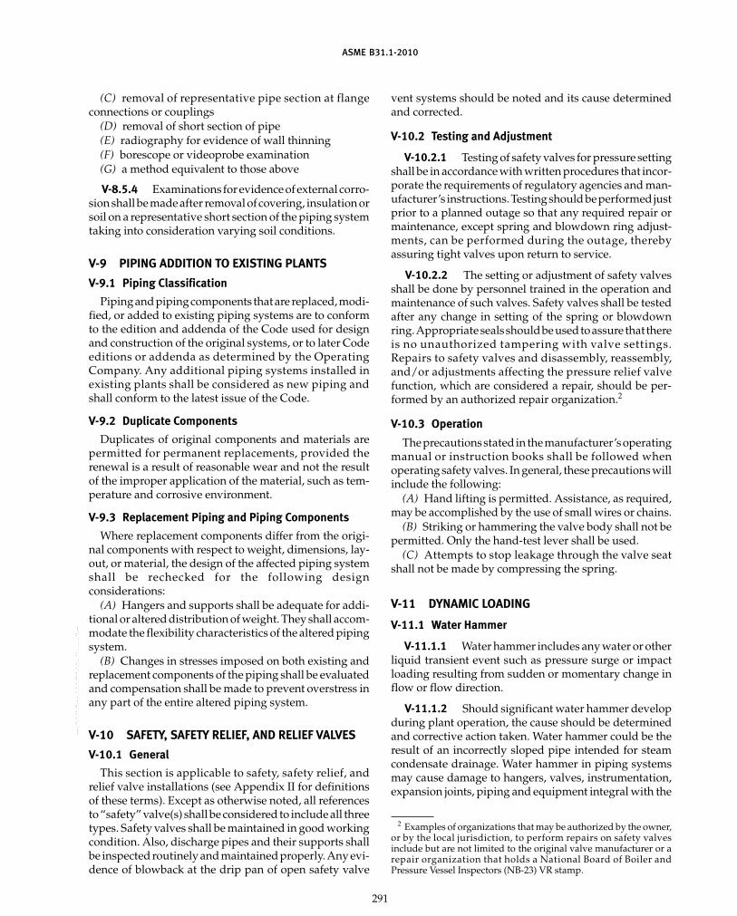
ASME B31.1-2010
(C) removal of representative pipe section at flangeconnections or couplings
(D) removal of short section of pipe(E) radiography for evidence of wall thinning(F) borescope or videoprobe examination(G) a method equivalent to those above
V-8.5.4 Examinations for evidence of external corro-sion shall be made after removal of covering, insulation orsoil on a representative short section of the piping systemtaking into consideration varying soil conditions.
V-9 PIPING ADDITION TO EXISTING PLANTS
V-9.1 Piping Classification
Piping and piping components that are replaced, modi-fied, or added to existing piping systems are to conformto the edition and addenda of the Code used for designand construction of the original systems, or to later Codeeditions or addenda as determined by the OperatingCompany. Any additional piping systems installed inexisting plants shall be considered as new piping andshall conform to the latest issue of the Code.
V-9.2 Duplicate Components
Duplicates of original components and materials arepermitted for permanent replacements, provided therenewal is a result of reasonable wear and not the resultof the improper application of the material, such as tem-perature and corrosive environment.
V-9.3 Replacement Piping and Piping Components
Where replacement components differ from the origi-nal components with respect to weight, dimensions, lay-out, or material, the design of the affected piping systemshall be rechecked for the following designconsiderations:
(A) Hangers and supports shall be adequate for addi-tional or altered distribution of weight. They shall accom-modate the flexibility characteristics of the altered pipingsystem.
(B) Changes in stresses imposed on both existing andreplacement components of the piping shall be evaluatedand compensation shall be made to prevent overstress inany part of the entire altered piping system.
V-10 SAFETY, SAFETY RELIEF, AND RELIEF VALVES
V-10.1 General
This section is applicable to safety, safety relief, andrelief valve installations (see Appendix II for definitionsof these terms). Except as otherwise noted, all referencesto “safety” valve(s) shall be considered to include all threetypes. Safety valves shall be maintained in good workingcondition. Also, discharge pipes and their supports shallbe inspected routinely and maintained properly. Any evi-dence of blowback at the drip pan of open safety valve
291
vent systems should be noted and its cause determinedand corrected.
V-10.2 Testing and Adjustment
V-10.2.1 Testing of safety valves for pressure settingshall be in accordance with written procedures that incor-porate the requirements of regulatory agencies and man-ufacturer’s instructions. Testing should be performed justprior to a planned outage so that any required repair ormaintenance, except spring and blowdown ring adjust-ments, can be performed during the outage, therebyassuring tight valves upon return to service.
V-10.2.2 The setting or adjustment of safety valvesshall be done by personnel trained in the operation andmaintenance of such valves. Safety valves shall be testedafter any change in setting of the spring or blowdownring.Appropriate sealsshouldbe usedtoassure that thereis no unauthorized tampering with valve settings.Repairs to safety valves and disassembly, reassembly,and/or adjustments affecting the pressure relief valvefunction, which are considered a repair, should be per-formed by an authorized repair organization.2
V-10.3 Operation
The precautions stated in the manufacturer’s operatingmanual or instruction books shall be followed whenoperating safety valves. In general, these precautions willinclude the following:
(A) Hand lifting is permitted. Assistance, as required,may be accomplished by the use of small wires or chains.
(B) Striking or hammering the valve body shall not bepermitted. Only the hand-test lever shall be used.
(C) Attempts to stop leakage through the valve seatshall not be made by compressing the spring.
V-11 DYNAMIC LOADING
V-11.1 Water Hammer
V-11.1.1 Water hammer includes any water or otherliquid transient event such as pressure surge or impactloading resulting from sudden or momentary change inflow or flow direction.
V-11.1.2 Should significant water hammer developduring plant operation, the cause should be determinedand corrective action taken. Water hammer could be theresult of an incorrectly sloped pipe intended for steamcondensate drainage. Water hammer in piping systemsmay cause damage to hangers, valves, instrumentation,expansion joints, piping and equipment integral with the
2 Examples of organizations that may be authorized by the owner,or by the local jurisdiction, to perform repairs on safety valvesinclude but are not limited to the original valve manufacturer or arepair organization that holds a National Board of Boiler andPressure Vessel Inspectors (NB-23) VR stamp.
Copyright ASME International Provided by IHS under license with ASME No reproduction or networking permitted without license from IHS
--`,,```````,,```,`,`,,,,`,`,`,`-`-`,,`,,`,`,,`---

ASME B31.1-2010
piping. The Operating Company should develop proce-dures to deter water hammer and to determine when cor-rective action is necessary.
V-11.1.3 Water hammer problems resulting fromaccumulated condensate in a steam line cannot be solvedsimply by adding restraints. Corrective action mayinclude changing line slopes, adding drain pots, addingwarm-up lines around valves, checking for leakingdesuperheaters, faulty electrical controls on automaticdrains, etc.
V-11.1.4 Water hammer due to column separationin feedwater or booster pump suction piping resultswhen the deaerator pegging pressure is not maintained.This type of water hammer can be particularly severe andrequires prompt attention to control and reduce it.
V-11.1.5 As a priority, corrective action shouldaddress the cause of water hammer first. If such correctiveaction is ineffective in reducing the effects of water ham-mer to acceptable levels, installation of restraints may benecessary to limit piping displacements and/or damagefrom fatigue.
V-11.2 Steam Hammer
V-11.2.1 Dynamic loads due to rapid changes inflow conditions and fluid state in a steam piping systemare generally called steam hammer loads. Pipingresponse to these momentary unbalanced loads can besignificant in high pressure steam systems, such as mainsteam, hot and cold reheat steam, bypass and auxiliarysteam systems that are subject to rapid interruption orestablishment of full steam flow.
V-11.2.2 The Operating Company should developprocedures to determine any adverse effects of steamhammer, such as excessive pipe movement, damage tohangers and restraints, and high pipe stress and reactionsat pipe connections to equipment. Where such move-ments, stresses, and reactions exceed safe limits or allow-able loadings, a program of remedial action should beimplemented.
V-12 HIGH-TEMPERATURE CREEP
V-12.1 General
V-12.1.1 Catastrophic failure, including rupture,can occur due to excessive creep strains resulting fromoperation of the piping above design pressure, or temper-atures, or both, for extended periods of time. Theexpected life of a piping system operating in the creeprange can be reduced significantly through prolongedexposure to pressure or temperature, particularly tem-perature, above design values. Paragraph 102.2.4 pro-vides criteria for occasional short operating periods athigher than design pressure or temperature.
292
V-12.1.2 The effect of temperature and time forequivalent creep damage is illustrated in Fig. V-12.1. ThisFigure indicates the approximate percentage change inoperating time to maintain an equivalent safety marginfor a variance in the continuous operation temperature.
For example, a component is designed for operation ata specific temperature. If the component operates at 5°C(9°F) below the design temperature, the operating timemay be increased about 45% to maintain the equivalentsafety margin on creep failure. If the component operatesat 5°C (9°F) above the design temperature, the operatingtime should be decreased about 30% to maintain theequivalent safety margin.
V-12.1.3 This section provides the minimumrequirements for evaluating critical piping systems inorder to detect creep damage and to assist in predictingthe remaining life under expected operating conditions.The remaining useful life may be estimated by determin-ing the extent of creep damage sustained by the pipe.
V-12.2 Procedures
V-12.2.1 The Operating Company shall establishprocedures to cover the requirements of this paragraph.
V-12.2.2 The procedures shall be carried out by orunder the direction of persons qualified by training orexperience in metallurgical evaluation of high tempera-ture creep effects in power plant piping.
V-12.2.3 An evaluation program to determine theextent of creep damage and estimate remaining life ofhigh temperature piping shall be carried out in threephases, as follows:
(A) review of material specifications, design stress lev-els, and operating history.
(B) indirect measurements to determine extent ofcreep damage. These would include diametral measure-ments to detectcreep swelling. In addition,dye penetrant,magnetic particle, ultrasonic, and radiographic methodsmay be used to detect internal and surface cracks.
(C) examinationof the microstructuretodeterminethedegree of material degradation. This can be performedby replication techniques or by metallography usingspecimens obtained by boat-sampling or trepanning.
V-12.3 Records
Records of creep damage evaluation survey findingsshall be maintained for the service life of high tempera-ture piping systems operating in the creep range.
V-12.4 Examination of Records
V-12.4.1 Records of creep damage surveys and testreports shall be examined by personnel qualified by train-ing and experience to evaluate and interpret NDE andmetallographical studies.
V-12.4.2 Where surveys and inspections of criticalpiping systems indicate that high temperature creep
Copyright ASME International Provided by IHS under license with ASME No reproduction or networking permitted without license from IHS
--`,,```````,,```,`,`,,,,`,`,`,`-`-`,,`,,`,`,,`---
标准分享网 www.bzfxw.com 免费下载

ASME B31.1-2010
Fig. V-12.1 Effect of Temperature and Operating Time for Equivalent Creep Damage
Continuous Operation Temperature Variance, C (F)
Op
erat
ing
Tim
e Va
rian
ce60%
40%
20%
0%
–20%
–40%
–60%
–80%
–100%–5 (–9) Design 5 (9) 10 (18) 15 (27) 20 (36)
damage has progressed to an unacceptable level, affectedportions of the piping system shall be replaced.
V-12.5 Frequency of Examination
V-12.5.1 Periodically, all critical piping systemsoperating within the creep range shall be examined forevidence of high temperature creep damage. Particularattention shall be given to welds.
V-12.5.2 The examination shall be repeated at peri-odic intervals that shall be established on the basis of ear-lier survey findings, operating history, and severity ofservice.
V-13 RERATING PIPING SYSTEMS
V-13.1 Conditions
An existing piping system may be rerated for use at ahigher pressure and/or temperature if all of the followingconditions are met:
(A) A design analysis shall be performed to demon-strate that the piping system meets the requirements ofthe Code at the new design conditions.
(B) The condition of the piping system and support/restraint scheme shall be determined by field inspections
293
and the examination of maintenance records, manufac-turer’s certifications, and/or other available informationto ensure conformance with the Code requirements forthe new design conditions.
(C) Necessary repairs, replacements, or alterations tothe piping system are made to conform with the require-ments prescribed in (A) and (B) above.
(D) The system has been leak tested to a pressure equalto or greater than that required by the Code for a newpiping system at the new design conditions.
(E) The rate of pressure and temperature increase tothe higher maximum allowable operating conditionsshall be gradual so as to allow sufficient time for periodicobservations of the piping system movements and leaktightness.
(F) Records of investigations, work performed, andpressure tests conducted in rerating the piping systemsshall be preserved for the service life of the pipingsystems.
(G) All safety valves, relief valves, and other pressurerelieving devices must be examined, and recertified forthe new pressure/temperature design conditions.Capacity of relieving equipment shall be investigated ifthe design pressure and/or temperature are changed inrerating a piping system.
Copyright ASME International Provided by IHS under license with ASME No reproduction or networking permitted without license from IHS
--`,,```````,,```,`,`,,,,`,`,`,`-`-`,,`,,`,`,,`---

ASME B31.1-2010
NONMANDATORY APPENDIX VIAPPROVAL OF NEW MATERIALS
The ASME B31.1 Committee considers requests foradoption of new materials desired by the owner/useror fabricator, manufacturer, installer, assembler of pipingor piping components constructed to the Code. For thematerial to receive proper consideration, informationand data are required to categorize the material properly.In general this information and data include, but arenot necessarily limited to, the following:
(A) the chemical composition of the material includ-ing those elements that establish the characteristics andbehavior of the material.
(B) the mechanical properties of the material, includ-ing tensile test data, ductility data, and other specialmechanical test data, which will assist the Committeein its review of the material and its application.
(B.1) tensile test data (per ASTM E 21), includingboth ultimate tensile strength and yield strength, at roomtemperature and at 100°F or 50°C intervals to a tempera-ture at least 100°F higher than the intended use of thematerial.
(B.2) when creep properties are expected to limitthe allowable stress, creep and creep rupture data attemperature intervals of 100°F or 50°C are also required.Such data should be for four or more time intervals, oneof which should be longer than 2,000 hr but less than6,000 hr, and one of which should be longer than 6,000 hr.
(C) if the material is to be used in welded construc-tion, data from actual welding tests made in accordancewith Section IX of the ASME Boiler and Pressure VesselCode should be submitted. Welding test data shouldinclude
(C.1) the welding processes and weld filler metal(s)intended for the fabrication of the material.
(C.2) all-weld-metal tensile test data for tempera-tures representative of intended service.
(C.3) any special restrictions on the welding of thematerial.
(C.4) the appropriate preheat and postweld heattreatment, if any, which will be given the material. Ifpostweld heat treatment results in embrittlement of thematerial, the significance of such treatments with sub-stantiating data should be forwarded. Toughness dataon weld metal and heat affected zone in the as-welded
294
and postweld heat treated conditions, when appro-priate, should be submitted.
(D) where the material is intended for special applica-tions, requires special handling or special welding proce-dures, or has known limitations or susceptibility tofailure in certain services, precautionary requirementsand information should also be submitted for reviewby the Committee.
(E) applicable product form(s) of the material, suchas sheet, strip, plate, bars, shapes, seamless or weldedpipe or tube forgings, castings, etc., for which applica-tion is to be considered must be identified.
The general data recommended should be submittedon a minimum of three heats, preferably commercialheats, of the material. Where the range of chemical com-position affects the mechanical properties, the heatsselected should cover both the high and low range ofthe effective chemical elements to show the effect onthe mechanical properties. Any special heat treatment,whether applied by the material supplier or the fabrica-tor, should be applied to the test pieces used to obtainthe data.
If the material is covered by an ASTM specification,the specification number(s) and grade(s) involved mustbe identified in the application. If the material is notcovered by an ASTM specification, application must bemade to ASTM for specification coverage of thismaterial.
Should there be a need for Code use prior to theinclusion of the material in ASTM specifications, theCommittee will consider issuing a Code Case.
In addition to the information and data noted above,the Committee should be provided with an indicationof user need, a copy of the letter to ASTM requestingspecification coverage, and sufficient information for theCommittee to modify an appropriate existing ASTMspecification to establish the material specificationrequirements for the material product form.
When the new material is a minor modification of amaterial which is currently accepted by the Code, thedata required may be reduced with the concurrence ofthe Committee. When the data supplied are insufficientfor an adequate evaluation, the Committee will requestadditional data. Such requests will be returned, indicat-ing those areas in which additional information isrequired.
Copyright ASME International Provided by IHS under license with ASME No reproduction or networking permitted without license from IHS
--`,,```````,,```,`,`,,,,`,`,`,`-`-`,,`,,`,`,,`---标准分享网 www.bzfxw.com 免费下载

ASME B31.1-2010
NONMANDATORY APPENDIX VIIPROCEDURES FOR THE DESIGN OF RESTRAINED
UNDERGROUND PIPING
FOREWORD
The Code contains rules governing the design, fabrica-tion, materials, erection, and examination of power pip-ing systems. Experience over the years hasdemonstrated that these rules may be conservativelyapplied to the design and analysis of buried piping sys-tems. However, the ASME B31.1 rules were written forpiping suspended in open space, with the supportslocated at local points on the pipe. Buried piping, onthe other hand, is supported, confined, and restrainedcontinuously by the passive effects of the backfill andthe trench bedding. The effects of continuous restraintcannot be easily evaluated by the usual methods appliedto exposed piping, since these methods cannot easilyaccommodate the effects of bearing and friction at thepipe/soil interface. Accordingly, this Appendix has beenprepared to illustrate and clarify the application of Coderules to restrained buried piping.
All components in the buried piping system must begiven consideration, including the building penetra-tions, branches, bends, elbows, flanges, valves, gradepenetrations, and tank attachments. It is assumed thatwelds are made in accordance with this Code and thatappropriate corrosion protection procedures are fol-lowed for buried piping.
This Appendix provides analytic and nomenclaturedefinition figures to assist the designer, and is notintended to provide actual design layout. Sample calcu-lations for various configurations of semirigid buriedpiping have been provided at the end of the text to assistthe designer in the application of these procedures.
VII-1 SCOPE AND DEFINITIONS
VII-1.1 Scope
The scope of this Appendix is confined to the designof buried piping as defined in para. VII-1.2. Thermalexpansion in buried piping affects the forces, theresulting bending moments and stresses throughout theburried portions of the system, particularly at theanchors, building penetrations, buried elbows andbends, and branch connections, and it is the designer’sresponsibility to consider these forces. This Appendix,however, deals only with the buried portions of thesystem, and not the complete system.
295
The design and analysis of buried piping requires thatcareful attention be paid to
(A) all loads acting on the system(B) the forces and the bending moments in the piping
and piping components resulting from the loads(C) the loading and stress criteria(D) general design practices
VII-1.2 Definitions
confining pressure: the pressure imposed by the com-pacted backfill and overburden on a buried pipe. Confin-ing pressure is assumed to act normal to the pipecircumference.
flexible coupling: a piping component that permits a smallamount of axial or angular movement while maintainingthe pressure boundary.
friction: the passive resistance of soil to axial movement.Friction at the pipe/soil interface is a function of confin-ing pressure and the coefficient of friction between thepipe and the backfill material. Friction forces exist onlywhere there is actual or impending slippage betweenthe pipe and soil.
influence length: that portion of a transverse pipe runwhich is deflected or “influenced” by pipe thermalexpansion along the axis of the longitudinal run.
modulus of subgrade reaction: the rate of change of soilbearing stress with respect to compressive deformationof the soil. It is used to calculate the passive spring rateof the soil
penetration: the point at which a buried pipe enters thesoil either at grade or from a wall or discharge structure.
settlement: the changes in volume of soil under constantload which results in the downward movement, over aperiod of time, of a structure or vessel resting on the soil.
virtual anchor: a point or region along the axis of a buriedpipe where there is no relative motion at the pipe/soilinterface.
VII-1.3 Nomenclature
A p cross-sectional metal area of pipe, in.2
Ac p surface area of a 1-in. long pipe seg-ment, in.2
a, b, c p quadratic equation functionsBd p trench width at grade, in.
Copyright ASME International Provided by IHS under license with ASME No reproduction or networking permitted without license from IHS
--`,,```````,,```,`,`,,,,`,`,`,`-`-`,,`,,`,`,,`---

ASME B31.1-2010
CD p soil bearing parameter fromTable VII-3.2.3, dimensionless
Ck p horizontal stiffness factor for backfill[8],1 dimensionless
D p pipe outside diameter, in.dL p length of pipe element, in.E p Young’s modulus for pipe, psiFf p total friction force along effective
length, lbFmax p maximum axial force in pipe, lb
f p unit friction force along pipe, lb/in.fmin, fmax p minimum, maximum unit friction force
on pipe, lb/in.H p pipe depth below grade, in.I p pipe section moment of inertia, in.4
k p soil modulus of subgrade reaction, psikh p soil horizontal modulus of subgrade
reaction, psiki,j p orthogonal soil springs on pipe, lb/in.kv p soil vertical modulus of subgrade reac-
tion, psiL1 p length of transverse pipe run, in.L2 p length of longitudinal pipe run, in.Lm p minimum slippage length of pipe, in.L′ p effective slippage length for short
pipes, in.L″ p effective slippage length for long
pipes, in.Nh p horizontal force factor [8],
dimensionlessn p number of modeling elements for pipe
springs, dimensionlessP p maximum operating pressure in pipe,
psiPc p confining pressure of backfill on pipe,
psiSA p allowable expansion stress range, psiSE p expansion stress, psiSh p basic material allowable stress at T
degrees Fahrenheit, psiT p maximum operating temperature, °FTo p ambient temperature of pipe, °F
t p pipe wall thickness, in.Wp p unit weight of pipe and contents, lb/in.
w p soil density, pcf, pci� p coefficient of thermal expansion of
pipe, in./in./°F� p pipe/soil system characteristic [2], in.−1
� p pipe unit thermal expansion, in./in.� p coefficient of friction, dimensionless p effective length parameter, in.
1 Numbers enclosed in brackets [ ] correspond to references citedin VII-7.
296
VII-2 LOADS
VII-2.1 Thermal Expansion
Thermal displacements at the elbows, branch connec-tions, and flanges in a buried piping system and theforces and moments resulting from the displacementsmay be determined by analyzing each buried run ofpipe by the method described in this Appendix.
VII-2.1.1 Installations With Continuous Runs. Forburied piping installations that contain continuous runswithout flexible couplings, the passive restraining effectsof soil bearing on the transverse legs at the ends of longruns subject to thermal expansion may be significantand result in high axial forces and elbow or branchconnection bending moments.
VII-2.1.2 Installations With Flexible Couplings. Forburied piping installations that incorporate flexible cou-plings into the pipe runs subject to thermal expansion,the bending moments and stresses may be substantiallyreduced. However, the flexible couplings must be chosencarefully to accommodate the thermal expansion in thepipe, and the friction forces or stiffness in the couplingmust be considered.
VII-2.1.3 Installations With Penetration Anchors.For buried piping systems in which the building pene-tration provides complete restraint to the pipe, it is nec-essary to calculate the penetration reactions to thermalexpansion in the initial buried run. If this run incorpo-rates flexible couplings, piping reactions at the penetra-tion resulting from unbalanced forces due to internalpressure must be considered.
VII-2.1.4 Installations With Flexible Penetrations.For buried piping systems in which the building pene-trations permit some axial or angular movements, theinteraction between the buried run outside the penetra-tion and the point-supported portion of the systeminside the building must be considered.
VII-2.2 Pressure
Pressure loads in buried piping are important for twoprimary reasons.
VII-2.2.1 In pipe runs which incorporate flexiblecouplings, there is no structural tie between the coupledends, with the result that internal pressure loads mustbe reacted externally. External restraint may be providedby thrust blocks, external anchors, soil resistance toelbows or fittings at each end of the pipe run, or bycontrol rods across the coupling. Where one or both ofthe ends terminate at a penetration or an anchor, or atconnected equipment such as a pump or vessel, thepressure forces can be quite high and must be consideredin the anchor or equipment design.
VII-2.2.2 For discharge strctures, the reaction forcesdue to upstream pressure and mass flow momentum in
Copyright ASME International Provided by IHS under license with ASME No reproduction or networking permitted without license from IHS
--`,,```````,,```,`,`,,,,`,`,`,`-`-`,,`,,`,`,,`---
标准分享网 www.bzfxw.com 免费下载

ASME B31.1-2010
the discharge leg may be high and must be considered inthe design of the last elbow or bend before the discharge.
VII-2.3 Earthquake
An earthquake subjects buried piping to axial loadsand bending moments from soil strain due to seismicwaves, or from ground faulting across the axis of thepipe. The seismic soil strain can be estimated for a designearthquake in a specific geographical region, from whichdesign values for forces and moments in buried pipingcan be calculated. However, consideration of the magni-tude and effects of seismic ground faulting on buriedpiping is beyond the scope of this Appendix.
VII-3 CALCULATIONS
The calculations for stresses in restrained under-ground piping are carried out in four steps, as follows.
VII-3.1 Assembling the Data
The pipe material and dimensions, soil characteristics,and operating conditions must be established.
VII-3.1.1 Pipe Data(A) pipe outside diameter, D, in.(B) wall thickness, t, in.(C) length of pipe runs, L1 (transverse) and L2
(longitudinal), in.(D) Young’s modulus, E, psi (from Appendix C)(E) pipe depth below grade, H, in.
VII-3.1.2 Soil Characteristics(A) soil density, w, pcf (from site tests)(B) type of backfill(C) pipe trench width at grade, Bd, in.(D) range of coefficient of friction, �, between pipe
and backfill
VII-3.1.3 Operating Conditions(A) maximum operating pressure, P, psi(B) maximum pipe temperature, T, °F(C) ambient pipe temperature, To, °F(D) pipe coefficient of thermal expansion,
�, in./in./°F
VII-3.2 Calculations of Intermediate Parameters
The parameters specified in paras. VII-3.2.1 throughVII-3.2.6 must be calculated.
VII-3.2.1 Maximum Relative Strain, �, at the Pipe/SoilInterface, in./in. For thermal expansion, this is the unitthermal elongation of the unrestrained pipe
� p �(T − To) (1)
where� p coefficient of thermal expansion
T − To p difference between operating and installa-tion temperatures
297
VII-3.2.2 Modulus of Subgrade Reaction, k, psi.This is a factor which defines the resistance of the soilor backfill to pipe movement due to the bearing pressureat the pipe/soil interface. Several methods for calculat-ing k have been developed in recent years by Audibertand Nyman [7], Trautmann and O’Rourke [8], and others[4, 5, 6]. For example [8], for pipe movement horizontally,the modulus of subgrade, kh, may be found by
kh p CkNhwD psi (2)
whereCk p a dimensionless factor for estimating hori-
zontal stiffness of compacted backfill. Ck maybe estimated at 20 for loose soil, 30 for mediumsoil, and 80 for dense or compacted soil.
D p pipe outside diameter, in.Nh p a dimensionless horizontal force factor from
Fig. 8 of [8]. For a typical value where the soilinternal friction angle is 30 deg, the curve from[8] may be approximated by a straight linedefined by
Nh p 0.285H/D + 4.3
whereH p the depth of pipe below grade at the
pipe centerline, in.
w p soil density, lb/in.3
For pipe movement upward or downward, the proce-dures recommended in [4] may be applied. Conserva-tively, the resistance to upward movement may beconsidered the same as for horizontal movement withadditional consideration for the weight of the soil.Resistance to downward movement may conservativelybe considered as rigid for most expansion stress analysis.
VII-3.2.3 Unit Friction Force at the Pipe/SoilInterface, f
f p � (PcAc + Wp) lb/in. (3)
whereAc p surface area of a pipe segment, in.2
Pc p confining pressure of soil on pipe, psiWp p unit weight of pipe and contents, lb/in.
� p coefficient of friction between pipe and soil
For piping that is buried within 3 pipe diameters ofthe surface, confining pressure, Pc, may be estimated by
Pc p wH lb/in.2
whereH p the depth below grade, in.w p the soil density, lb/in.3
Copyright ASME International Provided by IHS under license with ASME No reproduction or networking permitted without license from IHS
--`,,```````,,```,`,`,,,,`,`,`,`-`-`,,`,,`,`,,`---

ASME B31.1-2010
Table VII-3.2.3 Approximate Safe Working Valuesof CD for Use in Modified Marston Formula
Damp TopSoil and Damp Saturated
Ratio Dry and Saturated Yellow YellowH/BD Wet Sand Top Soil Clay Clay
0.5 0.46 0.47 0.47 0.481.0 0.85 0.86 0.88 0.901.5 1.18 1.21 1.25 1.272.0 1.47 1.51 1.56 1.622.5 1.70 1.77 1.83 1.91
3.0 1.90 1.99 2.08 2.193.5 2.08 2.18 2.28 2.434.0 2.22 2.35 2.47 2.654.5 2.34 2.49 2.53 2.855.0 2.45 2.61 2.19 3.025.5 2.54 2.72 2.90 3.186.0 2.61 2.91 3.01 3.32
6.5 2.68 2.89 3.11 3.447.0 2.73 2.95 3.19 3.557.5 2.78 3.01 3.27 3.658.0 2.82 3.06 3.33 3.749.0 2.88 3.14 3.44 3.89
10.0 2.92 3.20 3.52 4.01
11.0 2.95 3.25 3.59 4.1112.0 2.97 3.28 3.63 4.1913.0 2.99 3.31 3.67 4.2514.0 3.00 3.33 3.70 4.3015.0 3.01 3.34 3.72 4.34
� 3.03 3.38 3.79 4.50
For piping that is buried more than 3 pipe diametersbelow grade, confining pressure, Pc, is found by usingthe modified Marston equation [9]
Pc p wCDBD lb/in.2
whereBD p the trench width, with a maximum value of
24 in. plus the pipe diameterCD p a dimensionless parameter obtained from
Table VII-3.2.3
VII-3.2.4 Pipe/Soil System Characteristic [2]
� p [k/(4EI)]1/4 in. –1 (4)
whereE p Young’s modulus for pipe, psiI p area moment of inertia for pipe, in.4
k p soil modulus of subgrade reaction kh or kv, psi
VII-3.2.5 Minimum Slippage Length, Lm [1]
Lm p �AE/f in. (5)
whereA p pipe cross section area
298
VII-3.2.6 Maximum Axial Force, Fmax, in theLongitudinal Pipe Run. The maximum axial force in apipe long enough for friction force to develop to thepoint where a region of the pipe is totally restrainedlongitudinally by the soil is found by
Fmax p fLm p �AE lb (6)
VII-3.3 Classification of the Pipe Runs
VII-3.3.1 Purpose. The classification and subclassi-fication of the buried pipe elements is used in choosingthe proper equation for effective slippage length, L′ orL″, which is then used in calculating piping forces andstresses. The pipe segment identified by the dimensionL′ or L″ always begins at either an elbow, bend, tee, orbranch connection and terminates at the point(described below as the “virtual anchor”) at which thereis no slippage or relative movement at the pipe/soilinterface.
VII-3.3.2 Classification of the Pipe Elements. It isin the bends, elbows, and branch connections that thehighest stresses are found in buried piping subject tothermal expansion of the pipe. These stresses are dueto the soil forces that bear against the transverse run(the run running perpendicular or at some angle to thedirection of the pipe expansion). The stresses are propor-tional to the amount of soil deformation at the elbowor branch connection.
Piping elements are divided into three major catego-ries depending upon what type of transverse elementis being analyzed, as follows:
Category A: elbow or bend (see Fig. VII-3.3.2-1)
Category B: branch pipe joining the longitudinal run (seeFig. VII-3.3.2-2)
Category C: longitudinal run ending in a tee (seeFig. VII-3.3.2-3)
Category D: straight pipe, no branch or transverse run(see Fig. VII-3.3.2-4)
Categories A, B, and C are further divided into threesubcategories depending on the configuration of thepipe run at the end opposite that being analyzed. Thepiping elements are classified as follows:
A1, B1, C1: other end free or terminating in a flexiblecoupling or joint
A2, B2, C2: other end contains an elbow or tee
A3, B3, C3: other end is anchoredCategory D elements include straight runs between
an anchor (either actual or virtual) and a free end or apipe section that is connected to an expansion joint.
The elements are further broken down into subtypesdepending upon whether the longitundinal run (thepipe or P leg) and the transverse run (called the T leg)are long or short with respect to certain criteria. Thetransverse or T leg is the run against which the soil
Copyright ASME International Provided by IHS under license with ASME No reproduction or networking permitted without license from IHS
--`,,```````,,```,`,`,,,,`,`,`,`-`-`,,`,,`,`,,`---标准分享网 www.bzfxw.com 免费下载

ASME B31.1-2010
Fig. VII-3.3.2-1 Element Category A, Elbow or Bend
L′′, L′
T leg
P leg
Influencelength
Actualorvirtualanchor
k fε
θ
S M
Fig. VII-3.3.2-2 Element Category B, Branch PipeJoining the P Leg
L′′, L′
T leg
P legk fε
θ
S MInfluence
length
Actualorvirtualanchor
bears, producing an in-plane bending moment in elbow,branch, or tee. (Category D elements have no trans-verse leg.)
The strict criterion for a long or short transverse legis whether the length of the transverse run, L1, is longeror shorter than 3/4�, the length at which the hyperbolicfunctions in Hetenyi’s equations [2] approach unit. Thecritical value for L1 is often called the “influence” length,or that portion of transverse or T run which is deflectedor “influenced” by seismic soil strain or pipe thermalexpansion along the axis of the longitudinal or P run.In practice, a critical influence length, L1, of 1/� to 1.2/�may often be used, since there is very little deformationor load in that portion of the transverse run whichexceeds this length. This implies that the vast majorityof the bearing load on the transverse or T leg occurs inthe first several feet of the pipe at the bend or branch.In summary, a transverse pipe is “long” if
L1 ≥ 3/4� (conservative)
or
L1 ≥ 1/� to 1.2/� (usually acceptable)
The criterion for a short or long P leg is whether ornot its length, L2, is sufficiently long to experience themaximum force that can develop at the friction interface.For full maximum friction force (Fmax p �AE) to occurin a straight pipe axially free at each end, its length, L2,would have to equal or exceed 2Lm with Lm calculatedby eq. (5). If one end terminates in an elbow or a tee,with the other end remaining axially unrestrained, thetotal length, L2, necessary for full friction to develop is
299
Fig. VII-3.3.2-3 Element Category C, Tee on End of PLeg
L′′, L′
T leg
T leg
P legk
M
k
fε
MInfluencelength
Actualorvirtualanchor
Fig. VII-3.3.2-4 Element Category D, Straight Pipe
S
P leg
L′′, L′
fε
[Note (1)]
Actual or virtual anchor
NOTE:(1) Expansion joint pressure load plus sliding or convolution
loads.
L″ + Lm; the friction force over Lm is equal to the soilbearing force S plus the friction force acting on the lengthL′ or L″, which is called the effective slippage length.The effective slippage length is the maximum lengthalong which slippage occurs at the pipe/soil interfaceof a pipe with a transverse leg or branch. The effectiveslippage length, L″, for long pipes with long transverselegs is calculated by
L″ p [(1 + 2Fmax/f )1/2 − 1] in. (7)
where p AE�/k
and Fmax is calculated by eq. (6).Equation (7) applies to bends, tees, and branches.
Although eq. (7) was developed for the case where L2 pL″ + Lm, it applies also for any case where L2 > L″ + Lm,since the length of the region where there is zero slippageat the friction interface is immaterial [1]. Using L″ ascalculated by eq. (7), it can now be established that a Pleg is classified long if it meets these criteria:
(A) for Types A1, B1, C1, L2 ≥ Lm + L″(B) for Types A2, B2, C2, L2 ≥ 2L″(C) for Types A3, B3, C3, D, L2 ≥ L″That point which is located a distance L′ or L″ from
the bend, branch, or tee, is called the virtual anchor,since it acts as if it were a three-axis restraint on the pipe.
VII-3.3.4 Locating the Virtual Anchor. Calculationof the forces and moments in buried piping at thechanges in direction requires that the location of thevirtual anchor (the effective slippage length, L′, awayfrom the bend or branch element) in the P run and
Copyright ASME International Provided by IHS under license with ASME No reproduction or networking permitted without license from IHS
--`,,```````,,```,`,`,,,,`,`,`,`-`-`,,`,,`,`,,`---

ASME B31.1-2010
deformation, �, of the soil at the buried element be estab-lished. For elements of all types with long P legs, L″may be calculated by eq. (7).
For Types A1, B1, and C1 elements (with one end ofthe P leg free or unrestrained axially) with “short” P legs,L′ must be found by a less direct method as follows [1]:
L′ p [–b + (b2 – 4ac)1/2]/2a in. (8)
wherea p 3f/(2AE)b p � − fL2/(AE) + 2f�/kc p −f�L2/k
However, the most highly stressed runs in a buriedpiping system typically are restrained at both ends,either by a combination of transverse runs or a trans-verse and an anchor (either real or virtual).
For Types A2, B2, and C2 elements with short P legs,L′ is expressed by
L′ p L2/2 in. (9)
For Types A3, B3, C3, and D elements with short Plegs, L′ is expressed by
L′ p L2 in. (10)
VII-4 COMPUTER MODELING OF BURIED PIPING
VII-4.1 Determination of Stresses
With f, k, and L′ or L″ established, the stresses in aburied pipe due to thermal expansion can be determinedwith a general purpose pipe stress computer program.A buried piping system can be modeled with a typicalmainframe or microcomputer pipe stress program bybreaking the buried portions into elements of convenientlength and then imposing a transverse spring at thecenter of each element to simulate the passive resistanceof the soil. The entire pipe can be divided into spring-restrained elements in this manner; however, the onlyregions of the pipe that really need to be modeled inthis manner are the lengths entering and leaving elbowsor tees. The analyst should refer to the program users’manual for guidance in modeling soil springs.
All pipe stress computer programs with buried pipinganalysis options require that the following factors becalculated or estimated:
(A) location of the virtual anchor (dimension L′ or L″)(B) soil spring rate, ki,j, which is a function of the
modulus of subgrade reaction, k(C) influence length, also a function of kSome programs ignore the friction at the pipe/soil
interface; this is conservative for calculating bendingstresses on the buried elbows and branch connections,but may be unconservative for calculating anchorreactions.
300
VII-4.2 Determination of Element Lengths
The element lengths and transverse soil spring ratesfor each element are calculated by the followingprocedure.
VII-4.2.1 Establish the element length dL and thenumber n of elements, as follows:
(A) Set the element length to be equal to between 2and 3 pipe diameters. For example, dL for a NPS 6 maybe set at either 1 ft or 2 ft, whichever is more convenientfor the analyst.
(B) Establish the number n of elements by:
n p (3/4�)/dL (11)
This gives the number of elements, each being dL inchesin length, to which springs are to be applied in thecomputer model. The number, n, of elements is alwaysrounded up to an integer.
VII-4.2.2 Calculate the lateral spring rate, ki,j, tobe applied at the center of each element.
ki,j p kdL lb/in. (12)
wherek p the modulus of subgrade reaction calculated
from eq. (2).
VII-4.2.3 Calculate the equivalent axial load neces-sary to simulate friction resistance to expansion. Thefriction resistance at the pipe/soil interface can be simu-lated in the computer model by imposing a single forceFf in a direction opposite that of the thermal growth.
Ff p fL′/2 or fL′′/2 lb (13)
VII-4.2.4 Incorporate the springs and the frictionforce in the model. The mutually orthogonal springs ki,jare applied to the center of each element, perpendicularto the pipe axis. Shorter elements, with proportionallysmaller values for the springs on these elements, maybe necessary in order to model the soil restraint at elbowsand bends. The friction force, Ff, for each expanding legis imposed at or near the elbow tangent node, oppositeto the direction of expansion.
VII-4.3 Determination of Soil Parameters
Soil parameters are difficult to establish accuratelydue to variations in backfill materials and degree ofcompaction. Consequently, values for elemental springconstants on buried pipe runs can only be consideredas rational approximations. Stiffer springs can result inhigher elbow stresses and lower bending stresses atnearby anchors, while softer springs can have the oppo-site effects. Backfill is not elastic, testing has shown thatsoil is stiffest for very small pipe movements, butbecomes less stiff as the pipe movements increase. Refer-ences [4], [7], and [8] discuss soil stiffness and recom-mend procedures for estimating values for k which are
Copyright ASME International Provided by IHS under license with ASME No reproduction or networking permitted without license from IHS
--`,,```````,,```,`,`,,,,`,`,`,`-`-`,,`,,`,`,,`---标准分享网 www.bzfxw.com 免费下载

ASME B31.1-2010
consistent with the type of soil and the amount of pipemovement expected. The analyst should consult theproject geotechnical engineer for assistance in resolvingany uncertainties in establishing soils parameters, suchas the modulus of subgrade reaction, k; confining pres-sure, pc; and coefficient of friction, �.
VII-4.4 Pipe With Expansion Joints
An expansion joint must be considered as a relativelyfree end in calculating stresses on buried elbows andloads on anchors. Since incorporation of expansion jointsor flexible couplings introduces a structural discontinu-ity in the pipe, the effects of the unbalanced pressureload and the axial joint friction or stiffness must besuperimposed on the thermal expansion effects in orderto determine the maximum pipe stresses and anchorloads.
VII-4.5 Pipe Stresses at Building Penetrations
Stresses at building penetrations can be calculatedeasily after the reactions due to thermal expansion inthe buried piping have been determined. If the penetra-tion is an anchor, then the stress due to the axial force,Fmax, and the lateral bending moment, M, can befound by
SE p Fmax/A + M/Z psi (14)
If the penetration is not an anchor, but is instead asimple support with a flexible water seal, it is necessaryto determine the stiffness affects of the water seal mate-rial in order to calculate the stress in the pipe at thepenetration. Differential movement due to building ortrench settlement can generate high theoretical stressesat piping penetrations to buildings. Calculation of suchstresses is beyond the scope of this Appendix.
VII-5 ALLOWABLE STRESS IN BURIED PIPE
Buried piping under axial stress can theoretically failin one of two ways: either by column buckling (pipepops out of the ground at mid-span) or local failureby crippling or tensile failure (much more serious thancolumn buckling). Since buried piping stresses are sec-ondary in nature, and since the piping is continuouslysupported and restrained (see Fig. VII-5), higher totalstresses may be permitted as follows:
SC ≤ SA + Sh (15)
where SA and Sh are as defined in para. 102.3.2.
VII-6 EXAMPLE CALCULATIONS
VII-6.1 Assemble the Data
VII-6.1.1 Pipe Data(A) diameter, D p 12.75 in.(B) wall thickness p 0.375 in.
301
Fig. VII-5 Plan of Example Buried Pipe
20 ft
100 ft
400 ft
Pipe: NPS 12Material: SA-106 Grade B C.S.Depth below grade: 12 ftTrench width: 3 ft
L.R. elbow(typical)
B3
A
2
1
(C) length of runs:(C.1) Run 1: L1 p 100 ft, L2 p 400 ft(C.2) Run 2: L1 p 20 ft, L2 p 100 ft(C.3) Run 3: L1 p 100 ft, L2 p 20 ft
(D) Young’s modulus, E p 27.9 � 106 psi(E) moment of inertia, I p 279.3 in.4
(F) cross section metal area, A p 14.57 in.2
VII-6.1.2 Soil Characteristics(A) soil density, w p 130 lb/ft3
(B) pipe depth below grade, H p 12 ft (144 in.)(C) type of backfill: dense sand(D) trench width, Bd p 3 ft (36 in.)(E) coefficient of friction, � p 0.3 min. to 0.5 max.
(estimated)(F) horizontal soil stiffness factor, Ck p 80
VII-6.1.3 Operating Conditions(A) pressure, P p 100 psig(B) temperature p 140°F(C) ambient temperature p 70°F
VII-6.2 Calculate the Intermediate Parameters
VII-6.2.1 Relative Strain at the Pipe/Soil Interface.Thermal expansion for SA-106 Grade B carbon steel pipefrom 70°F to 140°F is 0.0053 in./ft. Therefore,
� p (0.0053 in./ft)/(12 in./ft)p 0.000424 in./in.
VII-6.2.2 Modulus of Subgrade Reaction, k [8]. Sincethe expansion is in the horizontal plane, use kh fromeq. (2):
kh p CkNhwD
Ck p 80
Nh p 0.285 H/D + 4.3p 0.285 (12 ft)(12 in./ft)/12.75 in. + 4.3p 7.519
w p 130 pcf/(1728 in.3/ft3)
p 0.0752 lb/in.3
D p 12.75 in.
khp(80)(7.519)(0.0752)(12.75) p 577 lb/in.2
Copyright ASME International Provided by IHS under license with ASME No reproduction or networking permitted without license from IHS
--`,,```````,,```,`,`,,,,`,`,`,`-`-`,,`,,`,`,,`---

ASME B31.1-2010
VII-6.2.3 Friction Forces Per Unit Length Acting at thePipe/Soil Interface
f p �(PcAc + Wp)
Since the pipe lies more than 3 diameters below grade,the modified Marston equation from [1] is used to deter-mine the confining pressure Pc of soil on the pipe.
Pc p wCDBd
CD p 2.22 for H/Bd p 12 ft/3 ftp 4 (see Table VII-3.2.3 for sand)
Pc p (130 pcf)(2.22)(3 ft)/(144 in.2/ft2)p 6.01 psi
Ac p D(1 in.) p (12.75 in.)(1 in.)
p 40.05 in.2/in. of length
Wp p 8.21 lb/in. for water-filled carbon steel pipe
Maximum value of friction force per unit length, fmax:
fmax p 0.5 [(6.01 psi)(40.05 in.2/in.) + 8.21 lb/in.]p 124.5 lb/in.
Minimum value of friction force per unit length, fmin:
fmin p 0.3 [(6.01)(40.05) + 8.21]p 74.7 lb/in.
VII-6.2.4 Pipe/Soil System Characteristic, � [2]
� p [kh/(4EI)]1/4
p [577 psi/4(27.9 � 106 psi)(279.3 in.4)]1/4
p 0.01166 in.−1
VII-6.2.5 Minimum Slippage Length, Lm
Lm p �AE/fmin
p (0.000424 in./in.)(14.57 in.2)(27.9 � 106 psi)/74.7 lb/in.
p 2,307 in. or 192 ft 4 in.
VII-6.2.6 Maximum Axial Force, Fmax, Correspondingto Lm
Fmax p �AE p (0.000424)(14.57)(27.9 � 106)p 172,357 lb
VII-6.3 Classification of Runs
Classify the pipe runs in accordance with the modelsgiven in Table VII-6.3 and calculate the effective slippagelength, L′ or L′′, for each run.
VII-6.3.1 Run 1 is a Category A1 (elbow on oneend, the other end free). Check to see if the transverseleg, L1, is long or short.
L1 p 1,200 in.
3/(4)(0.01166 in.−1) p 202 in.
302
Since 1,200 in. > 202 in., L1 is long. Check to see if thelongitudinal leg, L2, is long or short, that is, longer orshorter than Lm + L′′. Using eq. (7) to calculate L′′,
L′′ p [(1 + 2Fmax/fmin )1/2 − 1]
p AE�/k p (14.57 in.2)(27.9 � 106 psi)
� (0.01166 in.−1)/577 psi p 8,214 in.
L′′ p 8,214{[1 + 2 � 172,357/(74.7 � 8,214)]1/2 − 1}p 2,051 in.
Lm + L′′ p 2,307 + 2,051 p 4,358 in.
Since L2 p 400 ft or 4,800 in., then since 4,800 > 4,358,the pipe run length L2 is long, and Run 1 can be fullyclassified as Category A1 (long transverse, long pipe).NOTE: If Lm + L′′ would have exceeded L2, then L′ would berecalculated using eq. (8), the correct equation for a short pipe.
VII-6.3.2 Run 2 is a Category A2 (elbow on eachend). Check to see if the legs L1 and L2 are long or short.
Since L1 > 3/4� (240 in. > 202 in.) and L2 < 2L′′[1,200 in. < 2(2,051 in.)], then Run 2 can be fully classifiedas a Category A2 (long transverse, short pipe). Then
L′ p L2/2 p (1,200 in.)/2 p 600 in.
VII-6.3.3 Run 3 is a Category A3 (anchor on oneend, elbow on the other). Check to see if the legs L1 andL2 are long or short.
Since L1 > 3/4� (1,200 in. > 202 in.) and L2 < L′′(240 in. < 2,051 in.), then Run 3 can be fully classifiedas a Category A3 (long transverse, short pipe). Then
L′ p L2 p 240 in.NOTE: In order to fully qualify a buried piping system, it mayalso be necessary to include stresses due to weight of overburden(backfill) and vehicular loads [5, 6].
VII-6.4 Computer ModelingCalculate the soil springs and friction force for use in
a computer model of the buried pipe.
VII-6.4.1 Element Length. Set the element lengthto be ≈ 3 pipe diameters. dL p 36 in.
VII-6.4.2 Number of Elements. Only the soil withina length 3/4� from the elbow will be subject to bearingforce from the pipe. For the example system, 3/4� p202 in. Therefore, the number of elements needed isfound by
n p (3/4�)/dLp 202/36 p 5.61
Therefore, use six elements, each 36 in. long.
VII-6.4.3 Spring Rate, ki,j. The spring rate to beapplied to each element is found by
ki,j p kdL
where k is from eq. (2)
ki,j p (577 psi) (36 in.) p 20,772 lb/in.
Copyright ASME International Provided by IHS under license with ASME No reproduction or networking permitted without license from IHS
--`,,```````,,```,`,`,,,,`,`,`,`-`-`,,`,,`,`,,`---标准分享网 www.bzfxw.com 免费下载

ASME B31.1-2010
Table VII-6.3 Equations for Calculating Effective Length L′ or L″Equations for L′ or L″Element
Category Short P Leg L′ Long P Leg L″
A1, B1, C1 If L2 < Lm + L″,(8)
If L2 ≥ Lm + L″,(7)L′ p [−b + (b2 − 4ac)1/2]/2a L″ p [(1 + 2Fmax/fmin )1/2 − 1]
wherea p 3f /(2AE)b p � − fL2/(AE) + 2f�/kc p −f�L2/k
A2, B2, C2 If L2 < 2L″,(9) If L2 ≥ 2L″,
(7)L′ p L2/2
L″ p [(1 + 2Fmax/fmin )1/2 − 1]
A3, B3, C3 If L2 < L″,(10)
If L2 ≥ L″,(7)L′ p L2 L″ p [(1 + 2Fmax/fmin )1/2 − 1]
D If L2 < Lm,(10)
If L2 ≥ Lm,(5)L′ p L2 L″ p Lm p �AE/f
This is the theoretical spring rate to be imposed atthe center of each element and normal to the surface ofthe pipe, with ki in the plane of the expansion, and kjperpendicular to the plane of expansion.
VII-6.4.4 Friction Force, Ff. The friction forces to beapplied at the elbow tangent points in Runs 1 and 2 arecalculated as follows:
Parallel to Run 1:
Ff p fL′′/2
wheref p fmin p 74.7 lb/in.
L′′ p 2,051 in.
Ff p (74.7 lb/in.)(2,051 in.)/2p 76,605 lb
Parallel to Run 2:
Ff p (74.7 lb/in.)(600 in.)/2p 22,410 lb
The friction force to be applied at the elbow tangentpoint in Run 3 is calculated as follows:
Parallel to Run 3:
Ff p (74.7 lb/in.)(240 in.)/2p 8,964 lb
The computer model then appears as is shown inFig. VII-6.4.4.
303
VII-6.5 Results of Analysis
Computer analysis of the model shown inFig. VII-6.4.4 gives combined stress, SC, at various loca-tions in the buried pipe as follows:
Location SC, psi
Virtual anchor 7,036Elbow A 26,865Elbow B 9,818Penetration anchor 2,200
NOTE: SC for this example includes longitudinal pressure stress,intensified bending stresses, and direct stresses due to axial loadsfrom friction and soil bearing loads. It does not include weight ofbackfill or live loads.
The allowable stress as given by eq. (15) is SA + Sh,which for SA-106 Grade B steel pipe is 22,500 psi +15,000 psi p 37,500 psi. Therefore, since the maximumSC of 26,865 psi < 37,500 psi, the Code conditions are met.
VII-6.6 Anchor Load Example
If Element 1 were simply a straight pipe anchored atone end with the other end terminating in an expansionjoint (see Fig. VII-6.6), the load on the anchor is foundas follows:
(A) Calculate the maximum friction force acting alongthe friction interface.
Ff p Fmax p �AE
Fmax p �AE p (0.000424)(14.57)(27.9 � 106)p172,357 lb
Copyright ASME International Provided by IHS under license with ASME No reproduction or networking permitted without license from IHS
--`,,```````,,```,`,`,,,,`,`,`,`-`-`,,`,,`,`,,`---

ASME B31.1-2010
Fig. VII-6.4.4 Computer Model of Example Pipe
3
B2
A
1
20 ft 0 in.
100 ft 0 in.
170 ft 11 in.
400 ft 0 in.
Penetrationanchor
1 ft 6 in.3 ft 8 in. typical
Virtualanchor
NPS 12, Std. wall
1 ft 6 in
.
3 ft 8 in
. typical
Ff 2Ff 3
Ff 1 Ff 2
Kz
Ky
Ky
Ky
Kx = Ky = Kz = 20,772 lb/in.Ff 1 = 76,605 lbFf 2 = 22,410 lbFf 3 = 8,964 lb
Kz
KxKy
Kx
+X
+Y
+Z
Fig. VII-6.6 Example Plan of Element 1 as aCategory D Element
P leg
L′′
f
SAnchor
load Fa
400 ft
ε
(B) Calculate the load, S, at the expansion joint.
S p Fj + Sp
whereFj p expansion joint friction force
p 9,000 lb (from vendor data)Sp p pressure force
p PAswhere
P p design pressurep 100 psig
As p effective cross-sectional areap D2/4p (12.752)/4p 127.6 in.2
p (100)(127.6) p 12,760 lb
S p 9,000 + 12,760 p 21,760 lb
304
(C) The total axial load, Fa, at the anchor then becomes
Fa p 172,357 + 21,760 p 194,117 lb
If anchor loads must be limited, then the expansionjoint should be located closer to the anchor in order toreduce the force due to friction at the pipe/soil interface.
VII-7 REFERENCES
[1] Goodling, E. C., “Buried Piping — An AnalysisProcedure Update,” ASME Publication PVP — Vol. 77,pp. 225–237, ASME Pressure Vessels and PipingConference, Portland, June 1983
[2] Hetenyi, K. J., Beams on Elastic Foundation, TheUniversity of Michigan Press, Ann Arbor, Michigan,1967
[3] Hunt, R. J., et al., “Seismic Response of BuriedPipes and Structural Components,” Report by theSeismic and Materials Committee, ASCE, 1983
[4] Nyman, D. J., et al., Guidelines for the Seismic Designof Oil and Gas Piping Systems, Committee on Gas andLiquid Fuel Lifelines of the ASCE Technical Council onLifeline Earthquake Engineering, 1984
[5] Young, O. C., and Trott, J. J., Buried Rigid Pipes,Elsevier Applied Science Publishers, 1984
[6] Moser, A. P., Buried Pipe Design, McGraw-Hill, 1990[7] Audibert, J. M. E., and Nyman, K. J., “Soil Restraint
Against Horizontal Motion of Pipes,” Journal of the
Copyright ASME International Provided by IHS under license with ASME No reproduction or networking permitted without license from IHS
--`,,```````,,```,`,`,,,,`,`,`,`-`-`,,`,,`,`,,`---
标准分享网 www.bzfxw.com 免费下载

ASME B31.1-2010
Geotechnical Engineering Division, ASCE, Vol. 103, No.GT10, October 1977, pp. 1119–1142
[8] Trautmann, C. H., and O’Rourke, T. D., “LateralForce-Displacement Response of Buried Pipes,” Journalof Geotechnical Engineering, ASCE, Vol. 111, No. 9,September 1985, pp. 1077–1092
[9] Leonards, G. A., Editor, Foundation Engineering,McGraw-Hill, New York, 1962
305
[10] Goodling, E. C., “Restrained UndergroundPiping — Some Practical Aspects of Analysis andDesign,” Third U.S. Conference on Lifeline EarthquakeEngineering, ASCE, Los Angeles, August 22–24, 1991
[11] Antaki, George, and Hart, J.D., et al., “Guide forthe Design of Buried Steel Pipe,” American LifelinesAlliance under contract with FEMA and ASCE, July2001.
Copyright ASME International Provided by IHS under license with ASME No reproduction or networking permitted without license from IHS
--`,,```````,,```,`,`,,,,`,`,`,`-`-`,,`,,`,`,,`---

ASME B31.1-2010
INDEX
acceptable materialsstandards and specifications, 123.1, Table 126.1,
Appendix Faccess holes, 114.2.2air and hydraulic distribution systems, 100.1.2(E)alignment, 127.3(C)allowable stresses, shear, 102.3.1(B)allowable stress values, 102.3.1(A), Appendix Aaluminum pipe, 124.7(A)anchors, 119.7.1(A.3), 120.2.3anchors and guides, 120.2.3, 121.7.1annealing, definition, 100.2ANSI standards, Table 126.1, Appendix FAPI standards, Table 126.1, Appendix Farc welding, definition, 100.2ASME codes and standards, Table 126.1, Appendix FASME SA and SB specifications, 123.1assembly, 135assembly, definition, 100.2ASTM specifications, Table 126.1, Appendix FASTM standard test methods, Table 126.1,
Appendix Fattachments
design rules, 104.3.4structural, 121.8structural, definition, 100.2
attachment welds, 127.4.9automatic welding, definition, 100.2AWS filler metal specifications, Table 126.1,
Appendix FAWWA standards, Table 126.1, Appendix F
backing ring, definition, 100.2backing rings, 111.2.2, 127.2.2
acceptable types, 127.2.2(A.1)ferrous, 127.2.2(A)longitudinal welded joints, 127.2.2(A.3)nonferrous and nonmetallic, 127.2.2(B)
ball joints, 101.7.2, 119.5.1base metal, definition, 100.2bell end joints, 116bending, 102.4.5, 129
heat treatment, 129.3bends, 119.5bend thinning allowance, Table 102.4.5blanks, pipe, 108.2blowdown valves for instruments, 122.3.2(B.2)blowoff and blowdown piping, 122.1.7, 122.2blowoff valves, 122.1.7(C)boiler drains, 122.1.5
306
boiler external piping, 100.1.2(A), 122.1authorized installation, 127.5.3(C)carbon or alloy steel, 124.3(C)cast iron, 124.4ductile (nodular) iron, 124.6malleable iron, 124.5materials acceptable, 123.1, Table 126.1, Appendix Fmiscellaneous systems, 122.1.6specifications Table, 126.1, Appendix Fstandards Table, 126.1, Appendix Fsteel, carbon and alloy, 124.3
bolting, metric, 108.6bolting, piping flange, 108.5, Table 112bolting procedure, 135.3bolts, 108.5
engagement, 135.3.4bolt studs, 108.5, Table 112bonnet joint, valve, 107.5branch connections, 127.4.8
definition, 100.2design rules, 104.3.1extrusions, 104.3.1(G)multiple openings, 104.3.1(D.2.5)subject to external pressure, 104.3.1(E)weld design, 127.4.8
brazed joints, 117braze welding definition, 100.2brazing, 128
alloy, 117.1definition, 100.2filler metal, 128.2.1flux, 128.2.2heating, 128.4.2material, 128.2preparation, 128.3procedure, 128.4qualification, 128.5records, 128.6
butt joint, definition, 100.2butt welds
alignment, 111.2.1, 127.3(C)end preparation dimensions, 127.3(A.2)
bypasses, valve, 107.6bypass valves, 122.5.2 and 122.5.3
capacitor discharge welding (CDW), definition, 100.2carbon limitations
welded construction, 124.2(C)cast iron limitations, 124.4cast iron to steel flanged joints, 135.3.3
Copyright ASME International Provided by IHS under license with ASME No reproduction or networking permitted without license from IHS
--`,,```````,,```,`,`,,,,`,`,`,`-`-`,,`,,`,`,,`---标准分享网 www.bzfxw.com 免费下载

ASME B31.1-2010
central and district heating systems, 100.1.1, 100.1.2(B)centrifugally cast pipe, definition, 100.2cladding and lining materials, 124.8cleaning, welding, 127.3(B)cleaning fluid load, 101.6.3cold bending, 129.3.1, 129.3.3(B)cold spring, 119.2columns, water, 122.1.6(C)compression joints, 115concavity, girth butt welds, 127.4.2(C.5)condensing reservoirs, 122.3.2(C)connection, equipment, definition, 100.2connection branch, definition, 100.2constant supports, 121.7.4consumable inserts, 127.2.3contraction, 101.7control piping, 122.3.3cooling effect, 101.4.1copper pipe, 124.7(A)corrosion allowance, 102.4.1corrosion control, Appendix IVcorrosive liquids and gases, 122.9corrugated pipe, 119.5creep range, 119.3curved pipe, 104.2
dead load, 101.6.2defect, definition, 100.2definitions, 100.2design
cast iron, 124.4criteria, 102ductile (nodular) iron, 124.6malleable iron, 124.5nonferrous metals, 124.7nonmetallic pipe, 124.8steel, 124.3
design conditions, 101design pressure, 104.1.2(A)design temperature, 101.3.2desuperheaters, 122.4deterioration of materials, 124.10discontinuity, definition, 100.2dissimilar welds — backing, 127.2.2(A.2)district heating systems, 100.1.1, 122.14double submerged arc welded pipe, definition, 100.2drain piping, 122.1.5(A)drains, miniature boilers, valves, 122.1.5(C)drains, valve, 122.1.5(B)drip lines, 122.11.1ductile iron bell end piping, 135.7ductile (nodular) iron limitations, 124.6ductile iron pipe thickness, 104.1.2(B)ductility, 119.3dynamic effects, 101.5
307
earthquake loadings, 101.5.3elbows, 104.2.2electric flash welded pipe, definition, 100.2electric fusion welded pipe, definition, 100.2electric resistance welded pipe, definition, 100.2end preparation, welding, 127.3(A)ends, valve, 107.3engineering design, definition, 100.2entrapped pressure, valve, 107.1(C)equipment connection, definition, 100.2equivalent full temperature cycle, 102.3.2(C)erection, definition, 100.2erosion allowance, 102.4.1erosion/corrosion, Appendix IVexamination, 136.3
general, 136.3.1liquid penetrant, 136.4.4
acceptance standards, 136.4.4(B)evaluation of indications, 136.4.4(A)
magnetic particle, 136.4.3acceptance standards, 136.4.3(B)evaluation of indications, 136.4.3(A)
mandatory minimum requirements, Table 136.4radiography, 136.4.5
acceptance standards, 136.4.5(A)requirements, 136.4visual, 136.4.2
acceptance standards, 136.4.2(A)exhaust piping, 122.12expanded joints, 113expansion, 119
joints, 101.7.2properties, 119.6stress, 102.3.2(C)
external design pressure, 101.2.4extruded pipe, definition, 100.2extrusion, 129.2
fabrication, definition, 100.2face of weld, definition, 100.2facings, flange, 108.3, 108.5.2, Table 112federal specifications, Table 126.1, Appendix Ffeedwater piping, 122.1.3feedwater valves, 122.1.7(B)filler metal, 127.2.1
brazing, 128.2.1definition, 100.2
fillet weld, definition, 100.2fillet welds, 111.4
welding, 127.4.4fittings, 115fittings and joints for instrument, control, and
sampling piping, 122.3.6fixtures, 121.2flammable and toxic gases and liquids, 122.8flammable fluids, 117.3(A)
Copyright ASME International Provided by IHS under license with ASME No reproduction or networking permitted without license from IHS
--`,,```````,,```,`,`,,,,`,`,`,`-`-`,,`,,`,`,,`---

ASME B31.1-2010
flange, material combinations, Table 112flange bolting, pipe, 108.5, Table 112flanged elbows, 104.2.2flanged joints, 112, 135.2.1flange facings, 108.3, 108.5.2, Table 112flange gaskets, 108.4, 108.5.2, Table 112flanges, pipe, 108.1flared joints, 115flareless joints, 115flattening, 104.2.1(C)flaw, definition, 100.2flexibility, 119
factors, 119.7.3, Appendix Dflexible hose
metallic, 101.7.2, 106.4, 119.5, 121.7.1(C)nonmetallic, 105.3(D)
fluid expansion effects, 101.4.2flux, brazing, 128.2.2forged and bored pipe, definition, 100.2formed components, heat treatment, 129.3forming, 129.2full fillet weld, definition, 100.2furnace butt welded pipe, definition, 100.2fusion, definition, 100.2
gage cocks, 122.1.6(C)gage glass, 122.1.6
connections, 122.1.6(A)galvanic corrosion, 124.7(B)gaskets, pipe flange, 108.4, 108.5.2, Table 112gas welding, definition, 100.2geothermal systems, 100.1.2(B)girth butt welds, 127.4.2graphitization, 124.2(A) and (B)grinding, girth butt welds, 127.4.2(C.4)groove weld, definition, 100.2
hanger adjustments, 121.4hangers and supports, definitions, 100.2hanger spacing, 121.5heat affected zone, definition, 100.2heat exchanger piping, design temperature, 101.3.2(B)heating, brazing, 128.2.3heat treatment
austenitic stainless steel bends and formedcomponents, 129.3.4
bends, 129.3definition, 100.2formed components, 129.3heating and cooling requirements, 132.6, 132.7welds, 127.4.10, 131, 132, Table 132
impact, 101.5.1imperfection, definition, 100.2indication, definition, 100.2
308
inert gas metal arc weldingdefinition, 100.2
inquiries, Appendix Hinspection
instrument, control, and sampling piping, 122.3.9(A)requirements, 136.2
inspection and examination, 136general, 136.1.1verification of compliance, 136.1.2
inspectorsqualification of owner’s, 136.1.4rights of, 136.1.3
instrumentpiping, 122.3valves, 122.3.2(B)
integral type, 121.8.2internal design pressure, definition, 101.2.2internal pressure design, 104.1.2interruption of welding, 131.6intersections, 104.3
branch connections, 104.3.1design rules, 104.3
joint, butt, definition, 100.2joint, mechanical, definition, 100.2joint clearance, brazing, 128.3.2joint design, definition, 100.2joint efficiency, 102.3.2(C)joint penetration, definition, 100.2joints, valve bonnet, 107.5
lapping, 129.2level indicators, 122.1.6limitations on materials, 123.2live load, 101.6.1loads and supporting structures, 121.4local overstrain, 119.3local postweld heat treatment, 132.7longitudinal welds, 127.4.3loops, 119.5low energy capacitor discharge welding, 127.4.9(A)
main line shutoff valves, 122.3.2(A.1)malleable iron limitations, 124.5manual welding, definition, 100.2marking
materials, products, 123.1(E)valve, 107.2
materialsgeneral requirements, 123limitations, 124miscellaneous parts, 125
bolting, 125.4gaskets, 125.3
specifications and standards, 123.1, Table 126.1,Appendix F
stresses, 123.1
Copyright ASME International Provided by IHS under license with ASME No reproduction or networking permitted without license from IHS
--`,,```````,,```,`,`,,,,`,`,`,`-`-`,,`,,`,`,,`---标准分享网 www.bzfxw.com 免费下载

ASME B31.1-2010
maximum allowable internal pressure, 102.2.4maximum allowable temperature, 102.2.4maximum allowable working pressure, definition,
100.2may, definition, 100.2mechanical gland joints, 118mechanical joint, definition, 100.2mechanical strength, 102.4.4miniature electronic boiler, 122.1.4(A.1), 122.1.5(C)minimum wall thickness, 104.1.2(A)miscellaneous systems, 122.1.6miter, definition, 100.2miters, 104.3.3moduli of elasticity, Appendix Cmodulus of elasticity, 119.6.2, 199.6.4MSS standards, Table 126.1, Appendix F
nomenclature, Appendix Gnominal wall, 104.1.2(A)nonboiler external piping, 100.1.2(A)noncyclic service, 119.7(A.3)nonferrous material limitations, 123.2.7nonferrous pipe and tube, 104.1.2(C.3)nonintegral type, 121.8.1nonmetallic piping materials limitations, 124.9normalizing, definitions, 100.2normal operating condition, 102.2.3nuts, 108.5.1, Table 112
occasional loads, 102.2.4offsets, 119.5oil and flammable liquids, 122.7.1operation qualification
general, 127.5.1responsibility, 127.5.3(B)
operator, welding, definitions, 100.2other rigid types (fixtures), 121.7.2outside screw and yoke, valve, 107.4ovality, 104.2.1(B)overpressurization, Valve, 107.1(C)oxygen cutting, definition, 100.2oxygen gouging, definition, 100.2
peening, 100.2penetration, root, definition, 100.2PFI standards, Table 126.1, Appendix Fpipe
attachments, design rules, 104.3.4bends, 104.2.1blanks, 108.2definition, 100.2flange bolting, 108.5, Table 108.5.2flanges, 108.1intersections, design rules, 104.3supporting elements, definition, 100.2supporting elements, design, 121unions, 106.3, 115
309
piping joints, 100plastic strain, 119.3Poisson’s ratio, 119.6.3postweld heat treatment, 132
definition, 100.2definition of thickness governing PWHT, 132.4dissimilar metal welds, 132.2exemptions, 132.3furnace heating, 132.6heating and cooling rates, 132.5local heating, 132.7mandatory requirements, Table 132minimum holding temperature, Table 132minimum holding time, Table 132
preheating, 131definition, 100.2dissimilar metals, 131.2temperature, 131.4
preparation for welding, 127.3pressure
definition, 100.2entrapped liquids, valve, 107.1(C)gages, 122.1.6reducing valves, 107.1(G), 122.5, 122.14relief piping, 122.6temperature ratings, 102.2waves, 101.5.1
pressure testsgeneral requirements, 137.1
maximum stress during test, 137.1.4personnel protection, 137.1.3subassemblies, 137.1.1temperature of test medium, 137.1.2testing schedule, 137.1.5
hydrostatic, 137.4equipment check, 137.4.4material, 137.4.1required pressure, 137.4.5test medium, 137.4.3venting, 137.4.2
initial service, 137.7mass-spectrometer and halide, 137.6pneumatic, 137.5
equipment check, 137.5.3general, 137.5.1preliminary test, 137.5.4required presssure, 137.5.5test medium, 137.5.2
preparation for test, 137.2expansion joints, 137.2.3flanged joints containing blanks, 137.2.5isolation of piping and equipment, 137.2.4joint exposure, 137.2.1temporary supports, 137.2.2test medium expansion, 137.2.6
Copyright ASME International Provided by IHS under license with ASME No reproduction or networking permitted without license from IHS
--`,,```````,,```,`,`,,,,`,`,`,`-`-`,,`,,`,`,,`---

ASME B31.1-2010
retesting, 137.8specific piping systems, 137.3
boiler external piping, 137.3.1nonboiler external piping, 137.3.2
procedures, welding, definitions, 100.2proprietary joints, 118pump discharge piping, 122.13pump suction piping, 122.12
qualification, brazing, 128.5qualification, welding, 127.5
procedure responsibility, 127.5.3(A)responsibility, 127.5.2welder and welding operation responsibility,
127.5.3(B)quality control requirements for boiler external piping
(BEP), App. J
ratingsat transitions, 102.2.5variation from normal operation, 102.2.4
records, brazing, 128.6records, welding, 127.6reducers, 104.6reinforcement
branch connections, 104.3.1(D)of weld, definitions, 100.2of welds, Table 127.4.2zone, 104.3.1(D.2.4)
relief devices, 122.5.3, 122.14.1repair, weld defects, 127.4.11restraints, 119.5, 119.7.3reversed stress, 119.2ring, backing, definition, 100.2rolled joints, 113rolled pipe, definition, 100.2root opening, definitions, 100.2
safety valves, 107.8, 122.1.7(D), 122.5, 122.14.1sampling piping, 122.3.5(C)scope, 100.1seal weld
definition, 100.2welds, 111.5
thread joints, 127.4.5, 135.5.2seamless pipe, definition, 100.2self-springing, 119.2semiautomatic arc welding, definition, 100.2shall, definition, 100.2shielded metal arc welding, definition, 100.2shock, 117.3(C)should, definition, 100.2size of weld, definition, 100.2slag inclusion, definition, 100.2
310
sleeve coupled joints, 118snow and ice load, 101.6.1socket — type joints, 117socket welds, 111.3socket welds, assembly, 127.3(E)soldering
definition, 100.2filler metal, 128.2.1flux, 128.2.2flux removal, 128.4.3heating, 128.4.2material, 128.2preparation, 128.3procedure, 128.1.2soft soldered joints, 117.2, 117.3soldered joints, 117
spacing, welding, 127.3(D)special safety provisions — instrument, control, and
sampling piping, 122.3.7specifications, valve, 107.1(A)specifications and standards organizations, Table
126.1, Appendix Fspecific piping systems, design, 122springs, 121.6stamping, 133standards
acceptable, 123.1, Table 126.1, Appendix Fvalve, 107.1(A)
standard welding procedure specifications, 127.5.4statically cast pipe, definition, 100.2steam distribution systems, 122.14steam hammer, 101.5.1steam jet cooling systems, 100.1.2(D)steam piping, 122.1.2steam retention, 107.1(D)steam stop valves, 122.1.7(A)steam trap piping, 122.11steel
unassigned stress values, 102.3.1(D)unknown specification, 102.3.1(C)
steel casting quality factor, 102.4.6steel limitations
carbon content, 124.3(D)graphitization, 124.2(A) and (B)welding, 124.3(C)
stem threads, valve, 107.4strain, 119
concentration, 119.3distribution, 119.3range, 119.2
stress, 119.6.4analysis, 119.7bearing, 121.2(F)compressive, 121.2(E)concentration, 119.3external pressure, 102.3.2(B)
Copyright ASME International Provided by IHS under license with ASME No reproduction or networking permitted without license from IHS
--`,,```````,,```,`,`,,,,`,`,`,`-`-`,,`,,`,`,,`---
标准分享网 www.bzfxw.com 免费下载

ASME B31.1-2010
intensification, 119.7.1(D)factors, 111.2.1, 119.7.3
internal pressure, 102.3.2(A)limitations on materials, 123.2, Appendix Alimits, 102.3
occasional loads, 102.3.3longitudinal pressure, 102.3.2(D)raisers, 119.3range, 102.3.2(C), 119.2reduction, 119.2relaxation, 119.2relieving, definition, 100.2shear, 121.2(D)tension, 121.2
structural attachments, 121.8definitions, 100.2
submerged arc welding, definitions, 100.2supports, design, 119.5, 121
instrument, control, and sampling piping, 122.3.8surface condition, girth butt welds, 127.4.2(C)surface preparation, brazing, 128.3.1sway braces, 121.7.5swedging, 129.2swivel joints, 101.7.2, 119.5
tack weld, definitions, 100.2tack welds, 127.4.1(C)take-off connections, 122.3.2temperature, 101.3.1
graphitization, 124.3limitations
cast iron, 124.4ductile (nodular) iron, 124.6malleable iron, 124.5stress values, 124.1
temporary piping, 122.10terminal points, boiler external piping, 100.1.2(A)testing — instrument, control, and sampling piping,
122.3.9(A)test load, 101.6.3thermal contraction, 119.1thermal expansion, 101.7, 119, Appendix B
analysis, 119.7.1range, 119.6.1
threaded brass pipe, 104.1.2(C.2)threaded connections
aluminum pipe, 124.7(C)threaded copper pipe, 104.1.2(C.2)threaded joints, 114
lubricant, 135.5.1seal welded, 135.5.2
threaded piping, 135.5threaded steel pipe, 104.1.2(C.1)threading and grooving allowance, 102.4.2threads, valve stem, 107.4throat of fillet weld, definitions, 100.2
311
toe of weld, definitions, 100.2toxic fluids, 117.3(A)transients
pressure, 102.2.4temperature, 102.2.4
transitions, local pressure, 102.2.5transitions, O.D., 127.4.2(B)trap discharge piping, 122.11.2treatment, heat, definitions, 100.2tungsten electrode, definitions, 100.2
undercut, definitions, 100.2undercuts, girth butt welds, 127.4.2(C.3)unit expansion, 119.6.1upsetting, pipe ends, 129.2
vacuum, 101.4.1valves, 107
blowoff, 122.1.7(C)bonnet joint, 107.5bypasses, 107.6diaphragm, 107.1(F)drains, 107.1(C)ends, 107.3feedwater, 122.1.7(B)and fittings, 122.1.7flanged ends, 107.3general, 107.1marking, 107.2miniature boilers, 122.1.7(A.1.B)noncomplying designs, 107.1(B)pressure regulator, 107.1(G)safety, 107.8, 122.1.7(D)specifications, 107.1(A)standards, 107.1(A)steam stop, 122.1.7(A)threaded ends, 107.3welding ends, 107.3
variable supports, 121.7.3variations from normal operation, 102.2.4vibration, 101.5.4, 117.3(C)
washers, 108.5.1water
columns, 122.1.6hammer, 101.5.1level indicators, 122.1.6
weight effects, 101.6weld
concavity, 127.4.2(C.5)definitions, 100.2
weld, fillet, definition, 100.2weld, seal, definition, 100.2weld, tack, definition, 100.2weld defect repair, 127.4.11welded branch connections, 127.4.8
construction, carbon limitation, 124.2(C)welded joints, 111welder, definitions, 100.2
Copyright ASME International Provided by IHS under license with ASME No reproduction or networking permitted without license from IHS
--`,,```````,,```,`,`,,,,`,`,`,`-`-`,,`,,`,`,,`---
ASME B31.1-2010
welding, 127arc, definition, 100.2automatic, definition, 100.2braze, definition, 100.2end transition, Fig. 127.4.2filler metal, 127.2.1general, 127.1gun, definition, 100.2low energy capacitor discharge,
definition, 100.2manual, definition, 100.2material, 127.2
312
operator, definitions, 100.2preparation, 127.3procedure, 127.4process qualification, 127.1.1records, 127.6responsibility, 127.5.2
weld joint efficiency factor, longitudinal, 102.4.3weldment, definitions, 100.2weld reinforcement heights, Table 127.4.2weld surface preparation, 127.4.2(C)wind loadings, 101.5.2WPS, qualification, 127.5.1
Copyright ASME International Provided by IHS under license with ASME No reproduction or networking permitted without license from IHS
--`,,```````,,```,`,`,,,,`,`,`,`-`-`,,`,,`,`,,`---
标准分享网 www.bzfxw.com 免费下载
ASME B31.1 INTERPRETATIONS VOLUME 45
ASME B31.1INTERPRETATIONS VOLUME 45
Replies to Technical InquiriesJanuary 1, 2009 Through December 31, 2009
FOREWORD
It has been agreed to publish interpretations issued by the B31 Committee concerning B31.1as part of the update service to the Code. The interpretations have been assigned numbers inchronological order. Each interpretation applies either to the latest Edition at the time of issuanceof the interpretation or the Edition or Addenda stated in the reply. Subsequent revisions to theCode may have superseded the reply.
The replies are taken verbatim from the original letters, except for a few typographical andeditorial corrections made for the purpose of improved clarity. In some instances, a review ofthe interpretation revealed a need for corrections of a technical nature. In these cases, a revisedreply bearing the original interpretation number with the suffix R is presented. In the case wherean interpretation is corrected by errata, the original interpretation number with the suffix E is used.
ASME procedures provide for reconsideration of these interpretations when or if additionalinformation is available which the inquirer believes might affect the interpretation. Further,persons aggrieved by an interpretation may appeal to the cognizant ASME committee or subcom-mittee. As stated in the Statement of Policy in the Code documents, ASME does not “approve,”“certify,” “rate,” or “endorse” any item, construction, proprietary device, or activity.
I-1
Copyright ASME International Provided by IHS under license with ASME No reproduction or networking permitted without license from IHS
--`,,```````,,```,`,`,,,,`,`,`,`-`-`,,`,,`,`,,`---

ASME B31.1 INTERPRETATIONS VOLUME 45
B31.1
Subject Interpretation File No.
Definition of Sustained Pressure, Minimum Wall Thickness Calculation. . . . . . . . 45-2 06-1432Para. 101.7.2, Expansion Joints . . . . . . . . . . . . . . . . . . . . . . . . . . . . . . . . . . . . . . . . . . . . . 45-1 07-1440Para. 104.8.1, Pipe Nominal Wall Thickness . . . . . . . . . . . . . . . . . . . . . . . . . . . . . . . . . 45-4 08-1793Para. 122.3.2(b), Instrument Piping Valves . . . . . . . . . . . . . . . . . . . . . . . . . . . . . . . . . . 45-3 08-672Para. 131.6 . . . . . . . . . . . . . . . . . . . . . . . . . . . . . . . . . . . . . . . . . . . . . . . . . . . . . . . . . . . . . . 45-6 09-818Table 121.5, General Note (c) . . . . . . . . . . . . . . . . . . . . . . . . . . . . . . . . . . . . . . . . . . . . . . 45-7 09-971Table 136.4 . . . . . . . . . . . . . . . . . . . . . . . . . . . . . . . . . . . . . . . . . . . . . . . . . . . . . . . . . . . . . . 45-5 08-1755
I-2
Copyright ASME International Provided by IHS under license with ASME No reproduction or networking permitted without license from IHS
--`,,```````,,```,`,`,,,,`,`,`,`-`-`,,`,,`,`,,`---
标准分享网 www.bzfxw.com 免费下载

ASME B31.1 INTERPRETATIONS VOLUME 45
Interpretation: 45-1
Subject: B31.1-2007, Para 101.7.2, Expansion Joints
Date Issued: January 27, 2009
File: 07-1440
Question: Since para. 101.7.2 excludes bellows, slip, or sleeve type expansion joints from usein any piping system connecting the boiler and the first stop valve, are other types of expansionjoints excluded?
Reply: No.
Interpretation: 45-2
Subject: B31.1-2004, Definition of Sustained Pressure, Minimum Wall Thickness Calculation
Date Issued: February 6, 2009
File: 06-1432
Question (1): Is “maximum sustained pressure” referenced in para. 122.13 referring to the“maximum sustained operating pressure” exerted by the pump as described in para. 101.2.2?
Reply (1): Yes.
Question (2): When determining the value of P to be used in the minimum wall thicknessequations of para. 104.1.2, is it acceptable for the designer to take into account automated protectiondevices, such as safety/relief valves, to reduce the piping design pressure?
Reply (2): Yes.
Interpretation: 45-3
Subject: B31.1-2007, Para. 122.3.2(B), Instrument Piping Valves
Date Issued: April 13, 2009
File: 08-672
Question: Is it the requirement of para. 122.3.2(B.2.2) of the 2007 Edition of ASME B31.1, whenblowdown valves are used, that the rating of the valves at the instrument be equal to 1.5 timesthe design pressure of the piping system at 100°F and need not exceed the rating of the blowdownvalves?
Reply: Yes.
I-3
Copyright ASME International Provided by IHS under license with ASME No reproduction or networking permitted without license from IHS
--`,,```````,,```,`,`,,,,`,`,`,`-`-`,,`,,`,`,,`---

ASME B31.1 INTERPRETATIONS VOLUME 45
Interpretation: 45-4
Subject: Para. 104.8.1, Pipe Nominal Wall Thickness
Date Issued: May 26, 2009
File: 08-1793
Question: Should the pipe nominal wall thickness without deduction for mechanical, corrosion,and erosion allowance be used for the calculation of the section modulus to determine thelongitudinal stress due to weight and other sustained mechanical loads in para. 104.8.1, eq. (11)?
Reply: Yes.
Interpretation: 45-5
Subject: Table 136.4
Date Issued: July 1, 2009
File: 08-1755
Question (1): When the requirements of General Note (a) of Table 136.4 have been met, is 100%RT or UT required for all butt welds greater than NPS 2 with design temperatures over 750°F?
Reply (1): Yes.
Question (2): When the requirements of General Note (a) of Table 136.4 have been met, is 100%RT or UT required for all butt welds greater than NPS 2 and thickness over 3⁄4 in. with designtemperatures between 350°F and 750°F and pressures in excess of 1,025 psig?
Reply (2): Yes.
Interpretation: 45-6
Subject: B31.1-2004 Edition, Para. 131.6
Date Issued: September 17, 2009
File: 09-818
Question (1): Piping of material belonging to P-No. 3, 4, 5A, 5B, or 6 is tack welded using aqualified WPS. The tack welds are made using bridge tacks that will be slow cooled, removed,and the area examined for cracks prior to welding the joint. Per B31.1-2004 Edition, para. 131.6.1,does this tack weld constitute the commencement of welding that would then require the preheatto be maintained until the requirements of para. 131.6.1(A) or para. 131.6.1(C) are met?
Reply (1): No.
Question (2): Welding has been completed on piping of material belonging to P-No. 5B andhas been allowed to cool to 200°F or lower to achieve a fully martensitic microstructure just priorto performing the required PWHT. Per B31.1-2004 Edition, para. 131.6.1, does the weld describedin the background constitute an interruption of welding?
Reply (2): No.
I-4
Copyright ASME International Provided by IHS under license with ASME No reproduction or networking permitted without license from IHS
--`,,```````,,```,`,`,,,,`,`,`,`-`-`,,`,,`,`,,`---
标准分享网 www.bzfxw.com 免费下载

ASME B31.1 INTERPRETATIONS VOLUME 45
Interpretation: 45-7
Subject: Table 121.5, General Note (c)
Date Issued: November 30, 2009
File: 09-971
Question: Is the suggested pipe support spacing table based on stress not exceeding 2,300 psi(15.86 MPa) with a sag of no greater than 0.1 in. (2.5 mm) between supports?
Reply: Yes.
I-5
Copyright ASME International Provided by IHS under license with ASME No reproduction or networking permitted without license from IHS
--`,,```````,,```,`,`,,,,`,`,`,`-`-`,,`,,`,`,,`---

INTENTIONALLY LEFT BLANK
Copyright ASME International Provided by IHS under license with ASME No reproduction or networking permitted without license from IHS
--`,,```````,,```,`,`,,,,`,`,`,`-`-`,,`,,`,`,,`--- 标准分享网 www.bzfxw.com 免费下载

B31.1 — Cases No. 35
A Case is the official method of handling a reply to an inquiry when study indicates that theCode wording needs clarification, or when the reply modifies the existing requirements of theCode or grants permission to use new materials or alternative constructions.
ASME has agreed to publish Cases issued by the B31 Committee concerning B31.1 as part ofthe update service to B31.1. The text of proposed new and revised Cases appear on the ASMEWeb site at http://cstools.asme.org/csconnect/CommitteePages.cfm for public review. New andrevised Cases, as well as announcements of annulments, then appear in the next update. As ofthe 1992 and later editions, all Cases currently in effect at the time of publication of an editionare included with it as an update.
This update, Cases No. 35, which is included after the last page of the 2010 Edition and theInterpretations Volume 45 that follow, contains the following Cases:
175 176 177 182 183
The page numbers for the Cases supplements start with C-1 and continue consecutively. TheCases affected by this supplement are as follows:
Page Location Change
C-4 Case 176 Annulled
C-5 Case 177 Annulled
C-8 Case 183 In the Reply, paras. (d) and (f) revised
C-1
Copyright ASME International Provided by IHS under license with ASME No reproduction or networking permitted without license from IHS
--`,,```````,,```,`,`,,,,`,`,`,`-`-`,,`,,`,`,,`---

ASME B31.1 CASES
B31 CASE 175ASTM B 16 (UNS C36000) and B 453 (UNS C35300) in ASME B31.1 Construction
Approval Date: September 12, 2003
Reaffirmation Date: August 7, 2007
Inquiry: May brass alloys rods and bars conformingto ASTM B 16 (UNS C36000) and B 453 (UNS C35300)be used for ASME B31.1 construction?
Reply: It is the opinion of the Committee that brassalloys rods and bars conforming to ASTM B 16(UNS C36000) and B 453 (UNS C35300) may be usedfor B31.1 construction provided:
(a) These materials shall not be used for boiler exter-nal piping except where specifically permitted bySection I. See para. 100.1.2(A).
(b) The maximum permissible design temperatureshall not exceed 406°F (208°C).
(c) The maximum permissible size of finished productshall not exceed NPS 3.
(d) These materials shall not be welded.(e) These materials shall be used only in the soft
anneal (O60) temper.(f) Limitations for use of these materials for flamma-
ble liquids and gases shall be in accordance with paras.122.7, 122.8, and 124.7.
(g) Material conforming to ASTM B 16 alloyUNS C36000 shall not be used in primary pressure reliefvalve applications.
C-2
(h) A representative finished model of each productsize and design shall be tested to determine the presenceof residual stresses which might result in failure of indi-vidual parts due to stress corrosion cracking. Tests shallbe conducted in accordance with ASTM B 154 orASTM B 858M.
(i) Materials shall be tested to determine the presenceof residual stresses which might result in failure of indi-vidual parts due to stress corrosion cracking. Tests shallbe conducted in accordance with ASTM B 154 orASTM B 858M. The test frequency shall be as specifiedin B 249.
(j) Heat treatment after fabrication or forming is nei-ther required nor prohibited.
(k) The allowable stress values shown in Table 1 shallapply. These allowable stress values are based on a ten-sile strength factor of safety 4.0. These stress values maybe interpolated to determine values for intermediatetemperatures.
(l) The specified minimum tensile and yield strengthsshown in Table 1 shall apply.
(m) This Case number shall be referenced in the docu-mentation and marking of the material and recorded onthe Manufacturer’s Data Report.
Copyright ASME International Provided by IHS under license with ASME No reproduction or networking permitted without license from IHS
--`,,```````,,```,`,`,,,,`,`,`,`-`-`,,`,,`,`,,`---
标准分享网 www.bzfxw.com 免费下载

ASME B31.1 CASES
Table 1
Maximum Allowable Stress Values in Tension, ksi,for Metal Temperature, °F, Not ExceedingSpecified Specified
UNS Size or Minimum Minimum E −20Spec. Alloy Thickness, Tensile, Yield, or to
No. No. in. ksi ksi F 100 150 200 250 300 350 400 450
Rod
B 16 C36000 1 and under 48 20 1.00 13.3 12.6 12.0 11.5 11.1 10.7 5.3 2.0C36000 Over 1 to 2 44 18 1.00 12.0 11.3 10.8 10.4 10.0 9.7 5.3 2.0C36000 Over 2 40 15 1.00 10.0 9.4 9.0 8.7 8.3 8.1 5.3 2.0
B 453 C35300 Under 1⁄2 46 16 1.00 10.7 10.1 9.6 9.2 8.9 8.6 5.3 2.0C35300 1⁄2 to 1 44 15 1.00 10.0 9.4 9.0 8.7 8.3 8.1 5.3 2.0C35300 Over 1 40 15 1.00 10.0 9.4 9.0 8.7 8.3 8.1 5.3 2.0
Bar
B 16 C36000 1 and under 44 18 1.00 12.0 11.3 10.8 10.4 10.0 9.7 5.3 2.0C36000 Over 1 40 15 1.00 10.0 9.4 9.0 8.7 8.3 8.1 5.3 2.0
C-3
Copyright ASME International Provided by IHS under license with ASME No reproduction or networking permitted without license from IHS
--`,,```````,,```,`,`,,,,`,`,`,`-`-`,,`,,`,`,,`---

ASME B31.1 CASES
B31 CASE 176Use of 20Cr–18Ni–6Mo (UNS S31254) for ASME B31.1 Constructions
Annulment Date: July 12, 2010Reason for Annulment: Code Case was incorporated into the Code.
C-4
Copyright ASME International Provided by IHS under license with ASME No reproduction or networking permitted without license from IHS
--`,,```````,,```,`,`,,,,`,`,`,`-`-`,,`,,`,`,,`---
标准分享网 www.bzfxw.com 免费下载

ASME B31.1 CASES
B31 CASE 177Alternate Rules for Preheat of P-No. 5B Materials
Annulment Date: September 23, 2009Reason for Annulment: Code Case was incorporated into the Code.
C-5
Copyright ASME International Provided by IHS under license with ASME No reproduction or networking permitted without license from IHS
--`,,```````,,```,`,`,,,,`,`,`,`-`-`,,`,,`,`,,`---
ASME B31.1 CASES
B31 CASE 182Use of 1.15Ni–0.65Cu–Mo–Cb in ASME B31.1 Construction
Approval Date: November 10, 2006
Inquiry: May A 335-05a P36 Class 1 and Class 2, andA 182-05a F36 Class 1 and Class 2, be used for B31.1construction?
Reply: It is the opinion of the Committee thatA 335-05a P36 Class 1 and Class 2, and A 182-05a F36Class 1 and Class 2, may be used for B31.1 constructionprovided that all of the following requirements are met:
(a) All applicable requirements of ASME B31.1 shallbe met.
(b) The maximum allowable stress values and otherdata shown in Table 1 or 1M apply.
(c) Separate weld procedure and performance qualifi-cations shall apply for both classes of this material. Thepostweld heat treatment of the Class 1 and Class 2 mate-rial shall be in accordance with the rules specified inTable 2 or 2M.
(d) After either cold bending to strains in excess of5% or any hot bending of this material, the full lengthof the component shall be heat treated in accordancewith the requirements specified in the material specifica-tion. (See PG-19 of Section I for method for calculatingstrain.)
(e) Postweld heat treatment is mandatory under allconditions.
C-6
(f) This Case number shall be referenced in the docu-mentation and marking of the material, and recordedon the Manufacturer’s Data Report (if applicable).CAUTIONARY NOTE: Corrosion fatigue occurs by the com-bined actions of cyclic loading and a corrosive environment.In piping systems, corrosion fatigue is more likely to occur inportions of water systems with low strain rates (<1.0%/sec),higher temperatures [above 300°F (150°C)], and higher dissolvedoxygen (>0.04 ppm), with a preference toward regions withincreased local stresses. While the mechanisms of crack initiationand growth are complex and not fully understood, there is con-sensus that the two major factors are strain and waterside envi-ronment. Strain excursions of sufficient magnitude to fracturethe protective oxide layer play a major role. In terms of thewaterside environment, high levels of dissolved oxygen and pHexcursions are known to be detrimental. Historically, the steelsapplied in these water-touched components have had the mini-mum specified yield strengths in the range of 27 ksi to 45 ksi(185 MPa to 310 MPa) and minimum specified tensile strengthsin the range of 47 ksi to 80 ksi (325 MPa to 550 MPa). As thesematerials are supplanted by higher strength steels, some haveconcern that the higher design stresses and thinner wall thick-nesses will render components more vulnerable to failures bycorrosion fatigue. Thus, when employing such higher strengthsteels for water systems, it is desirable to use “best practices”in design by minimizing localized strain concentrations, in con-trol of water chemistry and during lay-up by limiting dissolvedoxygen and pH excursions, and in operation by conservativestartup, shutdown, and turndown practices.
Copyright ASME International Provided by IHS under license with ASME No reproduction or networking permitted without license from IHS
--`,,```````,,```,`,`,,,,`,`,`,`-`-`,,`,,`,`,,`--- 标准分享网 www.bzfxw.com 免费下载

ASME B31.1 CASES
Table 1 Maximum Allowable Stress Values
Maximum AllowableStress Values, ksiFor Metal Temperature
Not Exceeding, °F Class 1 Class 2
−20 to 100 25.7 27.3200 25.7 27.3300 25.1 26.6
400 25.1 26.6500 25.1 26.6600 25.1 26.6700 25.1 26.6
Table 1M Maximum Allowable Stress Values
Maximum AllowableStress Values, MPaFor Metal Temperature
Not Exceeding, °C Class 1 Class 2
−30 to 40 177 188100 177 188150 173 183200 173 183
250 173 183300 173 183350 173 183371 173 183
C-7
Table 2 Requirements for Postweld HeatTreatment (PWHT)
PWHTTemperature,
Class °F Holding Time
1 1,100–1,200 2 in. and less thickness: 1 hr/in., 15 minminimum
Over 2 in.: add 15 min for each additionalinch of thickness
2 1,000–1,150 1 hr/in., 1⁄2 hr min.
Table 2M Requirements for Postweld HeatTreatment (PWHT)
PWHTTemperature,
Class °C Holding Time
1 595–650 50 mm and less thickness: 1 hr/25 mm,15 min minimum
Over 50 mm: add 15 min for each addi-tional 25 mm of thickness
2 540–620 1 hr/25 mm, 1⁄2 hr min.
Copyright ASME International Provided by IHS under license with ASME No reproduction or networking permitted without license from IHS
--`,,```````,,```,`,`,,,,`,`,`,`-`-`,,`,,`,`,,`---

ASME B31.1 CASES
B31 CASE 183Use of Seamless 9Cr–2W in ASME B31.1 Construction
Approval Date: April 26, 2007
Inquiry: May seamless 9Cr–2W tubes, pipes, and forg-ings, with the chemical analysis shown in Table 1 andminimum mechanical properties as shown in Table 2that otherwise conform to the specifications listed inTable 3, be used for ASME B31.1 construction?
Reply: It is the opinion of the Committee that seamless9Cr–2W tubes, pipes, and forgings, with the chemicalanalysis shown in Table 1 and minimum mechanicalproperties as shown in Table 2 that otherwise conformto the specifications listed in Table 3, may be used forASME B31.1 construction provided the followingrequirements are met:
(a) The material shall be austenitized within the tem-perature range of 1,900°F to 1,975°F (1 040°C to 1 080°C),followed by air cooling or accelerated cooling, and tem-pered within the range of 1,350°F to 1,470°F (730°C to800°C).
(b) The material shall not exceed a Brinell hardnessnumber of 250 (Rockwell C 25).
(c) The maximum allowable stress values for thematerial shall be those given in Table 4. Maximum tem-perature of application shall be limited to 1,150°F(621°C), except that tubing used in applications up toand including 31⁄2 in. (89 mm) outside diameter may beused up to 1,200°F (649°C).
(d) Separate weld procedure qualification shall beconducted. For the purpose of performance qualifica-tions, the material shall be considered P-No. 15E,
C-8
Group 1. The procedure and performance qualificationsshall be conducted in accordance with Section IX. Post-weld heat treatment for this material is mandatory, andthe following rule shall apply: The PWHT requirementsshall be those given for P-No. 15E, Group 1 materialsin Table 132.
(e) Except as provided in para. (f), if during the manu-facturing any portion of the component is heated toa temperature greater than 1,470°F (800°C), then thecomponent must be reaustenitized and retempered inits entirety in accordance with para. (a), or that portionof the component heated above 1,470°F (800°C), includ-ing the heat-affected zone created by the local heating,must be replaced, or must be removed, reaustenitized,and retempered, and then replaced in the component.
(f) If the allowable stress values to be used are lessthan or equal to those provided in Table 1A of Section II,Part D for Grade 9 (SA-213 T9, SA-335 P9, or equivalentproduct specifications) at the design temperature, thenthe requirements of para. (e) may be waived, providedthat the portion of the component heated to a tempera-ture greater than 1,470°F (800°C) is reheat treated withinthe temperature range 1,350°F to 1,425°F (730°C to775°C).
(g) This Case number shall be shown on the Manufac-turer’s Data Report.
(h) This Case number shall be shown in the materialcertification and marking of the material.
Copyright ASME International Provided by IHS under license with ASME No reproduction or networking permitted without license from IHS
--`,,```````,,```,`,`,,,,`,`,`,`-`-`,,`,,`,`,,`---
标准分享网 www.bzfxw.com 免费下载

ASME B31.1 CASES
Table 1 Chemical Requirements
Element Composition Limits, %
Carbon 0.07–0.13Manganese 0.30–0.60Phosphorus, max. 0.020Sulfur, max. 0.010
Silicon, max. 0.50Chromium 8.50–9.50Molybdenum 0.30–0.60Tungsten 1.50–2.00
Nickel, max. 0.40Vanadium 0.15–0.25Columbium 0.04–0.09Nitrogen 0.030–0.070
Aluminum, max. 0.02Boron 0.001–0.006Titanium, max. 0.01Zirconium, max. 0.01
Table 2 Mechanical Property Requirements
Property Min. Value
Tensile strength 90 ksiYield strength 64 ksiElongation in 2 in. [Note (1)] 20%
NOTE:(1) For longitudinal strip tests, a deduction from the basic values
of 1.00% for each 1⁄32-in. decrease in wall thickness below5⁄16 in. shall be made. Below are the computed minimum elon-gation values for each 1⁄32-in. decrease in wall thickness.Where the wall thickness lies between two values shownbelow, the minimum elongation value shall be determined bythe following equation:
E p 32t + 10.0
whereE p elongation in 2 in., %t p actual thickness of specimen, in.
Elongation in 2 in.,Wall Thickness, in. min., %
5⁄16 (0.312) 20.09⁄32 (0.281) 19.01⁄4 (0.250) 18.07⁄32 (0.219) 17.03⁄16 (0.188) 16.05⁄32 (0.156) 15.01⁄8 (0.125) 14.03⁄32 (0.094) 13.01⁄16 (0.062) 12.0
0.062 to 0.035, excl. 11.60.035 to 0.022, excl. 10.90.022 to 0.015, incl. 10.6
C-9
Table 3 Specifications
Product Form Spec. No.
Forgings SA-182Forged pipe SA-369Pipe SA-335Tube SA-213
Table 4 Maximum Allowable Stress Values forTube and Pipe
Maximum Allowable StressValues, ksi
For Metal Temperature Forgings, Pipe,Not Exceeding, °F Tube Forged Pipe
−20 to 100 25.7 25.7200 25.7 25.7300 25.3 25.3400 24.5 24.5500 23.8 23.8600 23.2 23.2
650 22.8 22.8700 22.4 22.4750 21.9 21.9800 21.4 21.4850 20.8 20.8900 20.1 20.1
950 19.2 19.21,000 18.3 18.31,050 16.1 15.71,100 12.3 12.01,150 8.9 8.61,200 5.9 5.6
GENERAL NOTE: The allowable stress values are based on therevised criterion for tensile strength at temperature divided by 3.5,where applicable.
Copyright ASME International Provided by IHS under license with ASME No reproduction or networking permitted without license from IHS
--`,,```````,,```,`,`,,,,`,`,`,`-`-`,,`,,`,`,,`---
INTENTIONALLY LEFT BLANK
Copyright ASME International Provided by IHS under license with ASME No reproduction or networking permitted without license from IHS
--`,,```````,,```,`,`,,,,`,`,`,`-`-`,,`,,`,`,,`---
标准分享网 www.bzfxw.com 免费下载
INTENTIONALLY LEFT BLANK
Copyright ASME International Provided by IHS under license with ASME No reproduction or networking permitted without license from IHS
--`,,```````,,```,`,`,,,,`,`,`,`-`-`,,`,,`,`,,`---

A05810
ASME B31.1-2010
Copyright ASME International Provided by IHS under license with ASME No reproduction or networking permitted without license from IHS
--`,,```````,,```,`,`,,,,`,`,`,`-`-`,,`,,`,`,,`---
标准分享网 www.bzfxw.com 免费下载


