An intra-vehicular wireless sensor network is designed and implemented on a software-defined radio system. IUWB signal ischosen to carry the data packets. The MAC layer of the system follows the specification of the IEEE802.15.4 standard. Thetransceiver design, especially the receiver design, is detailed in the paper. The system design is validated through lab test setup.
1. Introduction
Modern vehicles are equipped with a multitude of sensorsto collect data that are essential for proper operation of thevehicle. These sensor data include vital information suchas exhaust quality and lateral velocity which affect drivingsafety and environment friendliness, as well as informationfor improving the comfort and convenience of passengers. Asa trend, more and more sensors will be added in the futureto make automobiles “smarter”. Currently, these sensors areconnected to the Electronic Control Unit (ECU) via cables.By 2002, the length of these cables has already added upto over 1000 meters and weighed more than 50 kg, andthe cable length still increases rapidly [1]. These cablesnot only adversely affect the cost and fuel economy, butalso increase the complexity of the vehicle design. Anothermajor drawback brought by the cables is the scalability issue.Whenever a new sensor is added to a car, a cable has to beadded and routed properly inside the car body. The cable mayinterfere with other components. In this case, much moreredesign work is necessary than simply adding the sensoralone. One way to reduce the undesirable effect caused by thebundle of wires is to connect sensors with the ECU wirelessly.Hence, ElBatt et al. proposed a wireless sensor network forintra-vehicular sensor data transmission [2].
Since some sensor data are essential for the safety of thevehicle, it is important for the intra-vehicular wireless sensornetwork (IV-WSN) to provide the same level of reliability
and transmission latency as offered in the current wiredsystem. This requirement differentiates the IV-WSN from theexisting sensor networks and imposes a big challenge in thedesign of the WSN, especially at the physical layer, whichdetermines the data integrity and data rate. Another factor tobe emphasized in the WSN design is the power consumption.Removing wires means removing not only the data cables butalso power supply cables. The sensors have to rely on otherpower sources. Vibration energy can be one viable source[3]. Energy harvesting for wireless sensors is by itself a hotresearch topic and will not be discussed further here. Weonly note that since the existing energy harvesting techniquescannot provide a large amount of power to the sensors, thereis a strict limit on the power budget for transceivers.
In addition to the two major requirements mentionedabove, many other issues are needed to be addressed in thedesign, including, but not limited to, cost, sensor heterogene-ity, wireless channel variation, modulation waveform, andnetworking. Without prior experience, a flexible platformsuch as a software defined radio (SDR) system is proper inthe early design phase to carry out different experiments.
The importance of removing the cables in vehicles hasbegun to attract attention only recently. Although someresearch has been done to study the viability of an IV-WSN[4, 5], to our knowledge, our system is the first SDR for IV-WSN. It will be very useful for future development of IV-WSN. Moreover, our SDR can handle very broadband signalsand will be found useful in many applications.
2 International Journal of Digital Multimedia Broadcasting
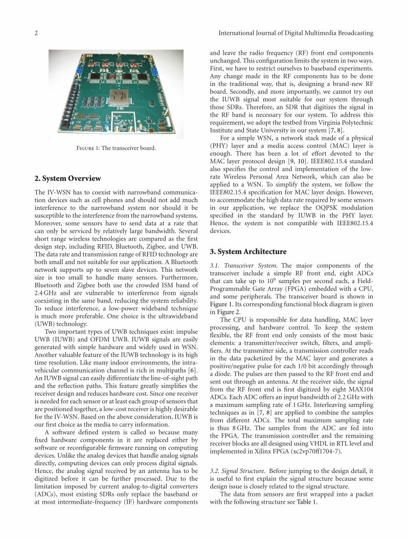
Figure 1: The transceiver board.
2. System Overview
The IV-WSN has to coexist with narrowband communica-tion devices such as cell phones and should not add muchinterference to the narrowband system nor should it besusceptible to the interference from the narrowband systems.Moreover, some sensors have to send data at a rate thatcan only be serviced by relatively large bandwidth. Severalshort range wireless technologies are compared as the firstdesign step, including RFID, Bluetooth, Zigbee, and UWB.The data rate and transmission range of RFID technology areboth small and not suitable for our application. A Bluetoothnetwork supports up to seven slave devices. This networksize is too small to handle many sensors. Furthermore,Bluetooth and Zigbee both use the crowded ISM band of2.4 GHz and are vulnerable to interference from signalscoexisting in the same band, reducing the system reliability.To reduce interference, a low-power wideband techniqueis much more preferable. One choice is the ultrawideband(UWB) technology.
Two important types of UWB techniques exist: impulseUWB (IUWB) and OFDM UWB. IUWB signals are easilygenerated with simple hardware and widely used in WSN.Another valuable feature of the IUWB technology is its hightime resolution. Like many indoor environments, the intra-vehicular communication channel is rich in multipaths [6].An IUWB signal can easily differentiate the line-of-sight pathand the reflection paths. This feature greatly simplifies thereceiver design and reduces hardware cost. Since one receiveris needed for each sensor or at least each group of sensors thatare positioned together, a low-cost receiver is highly desirablefor the IV-WSN. Based on the above consideration, IUWB isour first choice as the media to carry information.
A software defined system is called so because manyfixed hardware components in it are replaced either bysoftware or reconfigurable firmware running on computingdevices. Unlike the analog devices that handle analog signalsdirectly, computing devices can only process digital signals.Hence, the analog signal received by an antenna has to bedigitized before it can be further processed. Due to thelimitation imposed by current analog-to-digital converters(ADCs), most existing SDRs only replace the baseband orat most intermediate-frequency (IF) hardware components
and leave the radio frequency (RF) front end componentsunchanged. This configuration limits the system in two ways.First, we have to restrict ourselves to baseband experiments.Any change made in the RF components has to be donein the traditional way, that is, designing a brand-new RFboard. Secondly, and more importantly, we cannot try outthe IUWB signal most suitable for our system throughthose SDRs. Therefore, an SDR that digitizes the signal inthe RF band is necessary for our system. To address thisrequirement, we adopt the testbed from Virginia PolytechnicInstitute and State University in our system [7, 8].
For a simple WSN, a network stack made of a physical(PHY) layer and a media access control (MAC) layer isenough. There has been a lot of effort devoted to theMAC layer protocol design [9, 10]. IEEE802.15.4 standardalso specifies the control and implementation of the low-rate Wireless Personal Area Network, which can also beapplied to a WSN. To simplify the system, we follow theIEEE802.15.4 specification for MAC layer design. However,to accommodate the high data rate required by some sensorsin our application, we replace the OQPSK modulationspecified in the standard by IUWB in the PHY layer.Hence, the system is not compatible with IEEE802.15.4devices.
3. System Architecture
3.1. Transceiver System. The major components of thetransceiver include a simple RF front end, eight ADCsthat can take up to 109 samples per second each, a Field-Programmable Gate Array (FPGA) embedded with a CPU,and some peripherals. The transceiver board is shown inFigure 1. Its corresponding functional block diagram is givenin Figure 2.
The CPU is responsible for data handling, MAC layerprocessing, and hardware control. To keep the systemflexible, the RF front end only consists of the most basicelements: a transmitter/receiver switch, filters, and ampli-fiers. At the transmitter side, a transmission controller readsin the data packetized by the MAC layer and generates apositive/negative pulse for each 1/0 bit accordingly througha diode. The pulses are then passed to the RF front end andsent out through an antenna. At the receiver side, the signalfrom the RF front end is first digitized by eight MAX104ADCs. Each ADC offers an input bandwidth of 2.2 GHz witha maximum sampling rate of 1 GHz. Interleaving samplingtechniques as in [7, 8] are applied to combine the samplesfrom different ADCs. The total maximum sampling rateis thus 8 GHz. The samples from the ADC are fed intothe FPGA. The transmission controller and the remainingreceiver blocks are all designed using VHDL in RTL level andimplemented in Xilinx FPGA (xc2vp70ff1704-7).
3.2. Signal Structure. Before jumping to the design detail, itis useful to first explain the signal structure because somedesign issue is closely related to the signal structure.
The data from sensors are first wrapped into a packetwith the following structure see Table 1.
International Journal of Digital Multimedia Broadcasting 3
ADC Demodulator
UART transmitter
RF
end
Transmittercontroller
UART receiver
Pulse train
Transmitter(transceiver 1)
Receiver(transceiver 2)
SensorSensor data
Sensor data
BRAMPacket
tx_idle
pkt_readyPacket information
Packet data
ADC data
BRAM
Decoded data
MEM_avail
Decoded packet content
Idle
ECUDecoded data
DecodeddataFPGA1
(xc2vp70ff1704-7) (xc2vp70ff1704-7)FPGA2
PPC(MAC layer,data service,
hardware control)
PPC(MAC
service,hardware control)
frontlayer,data
Positive
Negative
pulse (1)
pulse (0)
Figure 2: Transceiver block diagram.
1 bit Guarding period
Packet· · ·
Frame 1 Frame 2 Frame 3 · · ·
· · ·
Frame Nf
Chip NChip 4Chip 3Chip 2Chip 1
Figure 3: Signal structure.
Table 1
Bits: 32 8 8 Variable
Preamble SFD Frame Len Payload
The preamble bits are all “1”s and are known at thereceiver. The preamble is used as a pilot to learn the wirelesschannel. The Start of Frame Delimiter (SFD) is a byte offixed value. The frame length byte records the length of thepayload in bytes. The payload comes from the MAC layerwhich contains the sensor data and the MAC header.
At the signal level, each bit is made of Nb frames. Eachframe is further divided into Nf time slots called chips. Theduration of a chip equals the length of a transmitted pulse.Within each frame, only one chip contains a pulse. Otherchips are empty. The index of the chip containing the pulsevaries from one frame to the next and follows the pattern of atime-hopping (TH) sequence of length Nth. Nf can be equalto or greater than Nth. The large Nf is useful for removingany intersymbol interference (ISI). The signal structure isgiven in Figure 3. According to this structure, the transmittedsignal can be written as
s(t) =∑
i
b�i/Nb�p(t − iT f − c[i/N f ]Tc
), (1)
where bn is the bit sequence, p(t) is the transmittedwaveform, Tf is the frame duration, Tc is the chip duration,and cn is the time-hopping sequence.
3.3. Receiver Design. Each multipath attenuates and delaysthe transmitted signal differently. Assuming there are L paths,the received signal can be represented as
r(t) =L∑
l=1
als(t − τl), (2)
where al and τl represents the path amplitude and delay,respectively.
We use a coherent receiver in our system. A coherentreceiver demodulates the signal by correlating the receivedsignal with a local template and determining the bit valuebased on the correlation result. Letting g(t) be the localtemplate, the correlation result is
R(τ) =∫ Tf
0r(t)g(t, τ)dt. (3)
As explained in the next two sections, different templates areused in the timing acquisition phase and the demodulationphase.
The digitized signal from the ADCs passes through five-phase processing: energy detection, timing acquisition, bitdemodulation, packet synchronization, and packet demod-ulation. When the receiver powers up, after initialization, itenters an idle state. Once the CPU informs it that the upperlayer is ready, it begins to detect energy on the channel bycomparing the square of the received signal with a thresholdvalue. This procedure is realized through a correlator wherethe received signal itself is used as the local template. Ifenergy is detected on the channel, the receiver enters timingacquisition phase. The timing acquisition process determinesthe channel delay. If correct delay is acquired, future absolutecorrelation value should be larger than a given threshold.Only if this condition is met can the receiver move on tothe next phase. Otherwise, it returns to the energy detectionphase. In the next phase, the receiver first generates the localtemplate for demodulation purpose. Then, it demodulateseach bit and begins to search for the SFD pattern from thedemodulated bits. When the SFD field is found, it meansthat the packet level synchronization is reached. The nextbyte after the SFD should be the payload length. This valuedictates the number of bytes the receiver should demodulate
4 International Journal of Digital Multimedia Broadcasting
before it notifies the upper layer of the incoming packet andreturns to idle state, waiting for a new signal from the upperlayer. The whole process is illustrated in Figure 4.
When the demodulator receives a command from theCPU to begin receiving packets and enters the energydetection state, there may be a node already sending onthe channel. Even if the receiver is not receiving thepreambles, it may still pass the timing acquisition phaseand begin to demodulate bits. However, since there is nobyte in the payload that has the same pattern as SFD(this is ensured by the software), the demodulator neverreaches packet synchronization and may get stuck. To avoidthis scenario, a guarding period is added at the end ofa packet. Since a packet sent from one node will bereceived by all nodes, every node knows when the guardingperiod is. During this period, no sender will transmit apacket. While the demodulator searches for the SFD, it alsomonitors the absolute correlation value. If this value dropsbelow a threshold, it means that the end of a packet hasbeen reached. The demodulator automatically stops SFDsearch and jumps back to the energy detection phase. (Infact, even if a node fails to detect the previous packetand transmits during the guarding period, the channel itgoes through will be different from the previous sender.Since the demodulation template is one frame of thesignal from the previous sender, with high probability,this template would not have high correlation with thecurrent received signal and the correlation value test wouldfail. The receiver then goes back to the energy detectionphase).
3.4. Timing Acquisition. The narrowness of a pulse and thelow duty cycle of the pulse period of an IUWB signal imposea stringent requirement on the time accuracy at the receiverside. The fine timing resolution in IUWB systems resultsin a large search space, making timing acquisition a verychallenging problem. Long spreading sequences employedin typical IUWB systems further complicate the acquisitionproblem. Acquisition can be achieved by a noncoherentenergy detection scheme [11]. Since this scheme is moresensitive to noise, we focused only on coherent receivers. Ingeneral, the search space in the acquisition process is madeup of two subspaces: the one for the delay of the pulse withina chip and the one for the phase of the spreading sequence.The existing paper addresses only one aspect of the problem.Either the spreading code is assumed to be absent [12], or thechannel delay is assumed to be an integer number of pulsewidth [13]. There are two typical searching schemes: serialsearch and parallel search. Serial search scheme requiresvery simple hardware. However, its searching time is long.Multiple searches can be done in parallel to reduce the searchtime, but the hardware complexity increases a lot. Manytechniques have been proposed to speed up the searchingprocess without increasing hardware cost. However, theyeither require large computational complexity [14] or are notsuitable for the environment rich in multipaths [15, 16]. Inour system, a new acquisition scheme is developed to meetour needs [16].
The template used at the timing acquisition phase is thetransmitted signal received in the free space. This templateincorporates the characteristics of both transmitter antennasand receiver antennas without being affected by multipaths.Such a template can resolve the time delay of the channelvery well. Since this template is fixed, it is hardcoded in thereceiver.
In our new scheme, the timing acquisition process iscarried out in two steps: delay search and code search. Delaysearch determines the delay at the chip level. The receivedsignal is correlated with the local template and sampled at theend of each chip. After every Nd = Nf +maxi, j|ci−cj| samplehas been obtained, the template is delayed by Δτ, where Δτis the predefined search resolution and |ci − cj| representsthe number of chips between two pulses in the transmittedsignal. The delay search stops when the maximum value ofthe Nd samples is above a given threshold Th1. This happenswhen the received signal and the template are aligned on thechip boundary.
The code search follows the delay search and furtherlocates the phase of the TH sequence. When the code search
International Journal of Digital Multimedia Broadcasting 5
3214321432143214Phase 22
4321432143214321Phase 14
4321432143214321Phase 9
4321432143214321Phase 2
432142143214321Phase 1
24
23
22
21
20
19
18
17
16
15
14
13
12
11
10987654321
12314
141243
314121
21321141
2141
20
1574
3
tc
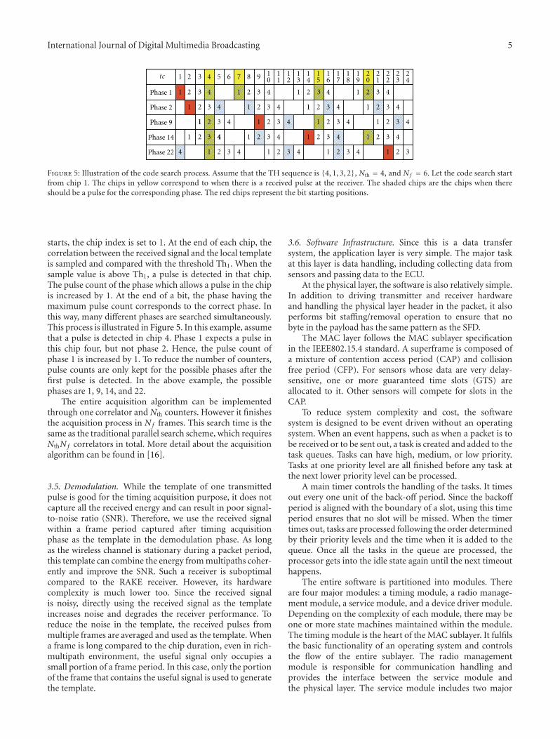
Figure 5: Illustration of the code search process. Assume that the TH sequence is {4, 1, 3, 2}, Nth = 4, and Nf = 6. Let the code search startfrom chip 1. The chips in yellow correspond to when there is a received pulse at the receiver. The shaded chips are the chips when thereshould be a pulse for the corresponding phase. The red chips represent the bit starting positions.
starts, the chip index is set to 1. At the end of each chip, thecorrelation between the received signal and the local templateis sampled and compared with the threshold Th1. When thesample value is above Th1, a pulse is detected in that chip.The pulse count of the phase which allows a pulse in the chipis increased by 1. At the end of a bit, the phase having themaximum pulse count corresponds to the correct phase. Inthis way, many different phases are searched simultaneously.This process is illustrated in Figure 5. In this example, assumethat a pulse is detected in chip 4. Phase 1 expects a pulse inthis chip four, but not phase 2. Hence, the pulse count ofphase 1 is increased by 1. To reduce the number of counters,pulse counts are only kept for the possible phases after thefirst pulse is detected. In the above example, the possiblephases are 1, 9, 14, and 22.
The entire acquisition algorithm can be implementedthrough one correlator and Nth counters. However it finishesthe acquisition process in Nf frames. This search time is thesame as the traditional parallel search scheme, which requiresNthNf correlators in total. More detail about the acquisitionalgorithm can be found in [16].
3.5. Demodulation. While the template of one transmittedpulse is good for the timing acquisition purpose, it does notcapture all the received energy and can result in poor signal-to-noise ratio (SNR). Therefore, we use the received signalwithin a frame period captured after timing acquisitionphase as the template in the demodulation phase. As longas the wireless channel is stationary during a packet period,this template can combine the energy from multipaths coher-ently and improve the SNR. Such a receiver is suboptimalcompared to the RAKE receiver. However, its hardwarecomplexity is much lower too. Since the received signalis noisy, directly using the received signal as the templateincreases noise and degrades the receiver performance. Toreduce the noise in the template, the received pulses frommultiple frames are averaged and used as the template. Whena frame is long compared to the chip duration, even in rich-multipath environment, the useful signal only occupies asmall portion of a frame period. In this case, only the portionof the frame that contains the useful signal is used to generatethe template.
3.6. Software Infrastructure. Since this is a data transfersystem, the application layer is very simple. The major taskat this layer is data handling, including collecting data fromsensors and passing data to the ECU.
At the physical layer, the software is also relatively simple.In addition to driving transmitter and receiver hardwareand handling the physical layer header in the packet, it alsoperforms bit staffing/removal operation to ensure that nobyte in the payload has the same pattern as the SFD.
The MAC layer follows the MAC sublayer specificationin the IEEE802.15.4 standard. A superframe is composed ofa mixture of contention access period (CAP) and collisionfree period (CFP). For sensors whose data are very delay-sensitive, one or more guaranteed time slots (GTS) areallocated to it. Other sensors will compete for slots in theCAP.
To reduce system complexity and cost, the softwaresystem is designed to be event driven without an operatingsystem. When an event happens, such as when a packet is tobe received or to be sent out, a task is created and added to thetask queues. Tasks can have high, medium, or low priority.Tasks at one priority level are all finished before any task atthe next lower priority level can be processed.
A main timer controls the handling of the tasks. It timesout every one unit of the back-off period. Since the backoffperiod is aligned with the boundary of a slot, using this timeperiod ensures that no slot will be missed. When the timertimes out, tasks are processed following the order determinedby their priority levels and the time when it is added to thequeue. Once all the tasks in the queue are processed, theprocessor gets into the idle state again until the next timeouthappens.
The entire software is partitioned into modules. Thereare four major modules: a timing module, a radio manage-ment module, a service module, and a device driver module.Depending on the complexity of each module, there may beone or more state machines maintained within the module.The timing module is the heart of the MAC sublayer. It fulfilsthe basic functionality of an operating system and controlsthe flow of the entire sublayer. The radio managementmodule is responsible for communication handling andprovides the interface between the service module andthe physical layer. The service module includes two major
6 International Journal of Digital Multimedia Broadcasting
ADC1
ADC2
Packet pulse 0
180
PBus1
ABus1
PBus2
ABus2
DDRarray
PBus1_0
PBus1_180
ABus1_0
ABus1_180
PBus2_0
PBus2_180
ABus2_0
PBus2_180
Sample FIFOarray
BRAM state
machine
BRAM array
ADC capture
DCR bus (master)
Demodulation
Demo FIFO
BRAM control signal
Data processing
unitCorrelator
Demodulation
Sequenced adjusted ADC data
Frame
RF front end
CPU(PHY)
data
array
Data path
Template data
ADC pointers setting
state machineBRAMDCR bus (slave)
Packet demodulation
result
control signals
FPGA(xc2vp70ff1704-7)
500 MHzCLK
Byte length&
debugging
250 MHzCLK
125 MHzCLK
Synchronizer&
phase shifterarrays
Figure 6: Receiver hardware blocks.
Data bus array
Design template
Demodulation FIFO
Data process unit1
Data process unit 2
Demodulationstate
machine
Correlator
Reset
Demodulation data
Cnt_demo
Data_ready
Data_end
Recv_state
Bit_addrBit_index
Syn_round_index
Data_decode
Sample_syn
Template_syn
Coefficient 2
Packet_length
Packet_content
Sample 2
Clock
Next_recv_state
BRAM& DCR
Figure 7: Demodulation unit internal structure.
International Journal of Digital Multimedia Broadcasting 7
Figure 8: Timing sequence of signals in the receiver.
Figure 9: Packet data decoding result printed from HyperTerminal.
components: (1) the MAC common part sublayer (MCPS)responsible for the data handling of the upper layer, (2) theMAC layer management entity (MLME) that manages otherservices generally more internal to the MAC layer. The devicedriver module includes all the low-level interfaces to thephysical devices and the I/O peripherals.
4. Receiver Hardware
The transmitter in an IUWB system is very simple. However,this often means more weight would be lifted by the receiverwhose design is detailed next.
Since the design of eight-ADC channels is very similar tothat of two-ADC channels, the design and implementationdetails of a two-ADC system are presented in this section. Asshown in Figure 6, The ADC capture unit consists of a DDRarray, a synchronizer, and phase shifter arrays, a sample FIFOarray, and a BRAM state machine. The DDR array in theFPGA reduces the data rate in the ADCs by a factor of 2 tomatch that of the internal bus in the FPGA. The synchronizerand phase shifter arrays make sure that each internal bus inthe FPGA is synchronized with the global clock and thereis a fixed phase shift between two buses. The data on eachinternal FPGA bus will be combined sequentially to form thefinal data stream. These data are also stored into the BRAMarray for debugging purpose. At power up, the order of theoutput data sequences from the ADCs does not necessarilyfollow the sequential order. For example, ADC2 may samplefirst while ADC1 may take the second sample. Through atesting signal, the CPU determines the order of the ADC
output data sequence and assigns a pointer to data sequencesfor them to be combined correctly for future use.
The internal structure of the demodulation unit isgiven in Figure 7. The demodulation unit consists of ademodulation FIFO, a data processing unit, correlators, anda demodulation state machine. The demodulation FIFOserves as a data buffer and stores the samples from thePLB bus as well as distributes the stored data to dataprocessing units. Data unit1 takes in the received data (fromthe demodulation FIFO) and the template data (from thememory) and adjusts the data format for the correlationprocedure. Data unit2 handles the template reconstruction,SFD searching, and packet demodulation. The demodulationstate machine generates the control signal for data processingand computation, as well as controlling the receiver togo through states based on the state machine diagram inFigure 4. The correlator is made of adder trees. It carries outthe correlation computation for timing acquisition and bitdemodulation.
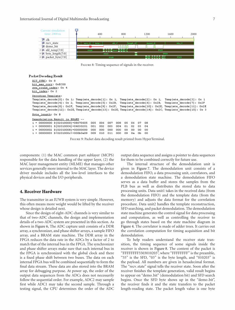
To help readers understand the receiver state tran-sition, the timing sequence of some signals inside thereceiver is shown in Figure 8. The content of the packet is“FFFFFFFF5503010203”, where “FFFFFFFF” is the preamble,“55” is the SFD, “03” is the byte length, and “010203” isthe payload. All numbers are given in hexadecimal format.The “recv state” signal tells the receiver state. Soon after thereceiver finishes the template generation, valid result beginsto appear on “demo bit” (demodulation bit) and SFD searchbegins. Once the SFD byte shows up in the “demo bit”,the receiver finds it and the state transfers to the packetlength-reading state. The packet length value is one byte
8 International Journal of Digital Multimedia Broadcasting
long and is correctly read as “03” in the “byte length” signal.The packet demodulation phase then begins. After 3 bytesare demodulated, as shown in the “packet byte” signal, thereceiver transitions into the idle state again.
In addition to validating the system through simulators,we also tested the entire system in the lab setup. Thefirst test only checks the physical layer. One transmit-ter sends out the data packet containing “FFFFFFFF550B0102030405060708090A0B”. The demodulated packet froma receiver is printed out on a computer screen, as shown inFigure 9. (The data bus in the receiver is eight bytes wide, andthe data bus in the memory is only four bytes wide. Whenthe data is stored in the memory, the first four bytes andthe second four bytes are stored in reverse order. MAC layerhandles this problem. Since the MAC layer is not involvedin this test, the data in the screen print is shown in reverseorder). No MAC layer processing is involved in this test.
The second test checks both the PHY layer and the MAClayer. A hyperterminal simulates a sensor and generates datato be sent out. The data are correctly received at a receiverand printed out.
Since we still have some problem in the antenna design,the tests are carried out through two units connected bya cable. Hence, rich-multipath environments, low-SNRscenarios, and network handling functions in the MAC layercannot be tested.
5. Conclusion
The design of an intra-vehicular wireless sensor networkis presented in this paper. Due to the high reliabilityrequired by the automobile sensors and the lack of priorexperience, we need a flexible system so that parameters,such as transmission waveforms, and power budgets, can beoptimized through tests in real environments. Hence, an SDRsystem is chosen to implement the design. Our system alsoproves the concept that a software radio can be realized atthe RF band without using any mixers. This proof is usefulin the expansion of the application areas of SDR systems andhopefully can also promote the development of SDR systems.
Acknowledgments
This paper is supported by the General Motor’s researchfund. The authors wish to thank Cem Saraydar and Tim Taltyfor their support of the project, Daniel Zehnder for sharinghis expertise in VHDL design, Hooman Shirani-Mehr for hissimulation effort, and David Shu and Simon Han for manyuseful discussions. The authors would also like to thank thereviewers for their insightful comments.
References
[1] G. Leen and D. Heffernan, “Vehicles without wires,” Comput-ing and Control Engineering Journal, vol. 12, no. 5, pp. 205–211, 2001.
[2] T. Elbatt, C. Saraydar, M. Ames, and T. Talty, “Potentialfor intra-vehicle wireless automotive sensor networks,” in
Proceedings of IEEE Sarnoff Symposium, Princeton, NJ, USA,March 2006.
[3] S. Roundy, P. K. Wright, and J. Rabaey, “A study of lowlevel vibrations as a power source for wireless sensor nodes,”Computer Communications, vol. 26, no. 11, pp. 1131–1144,2003.
[4] O. K. Tonguz, H.-M. Tsai, T. Talty, A. Macdonald, and C.Saraydar, “RFID technology for intra-car communications: anew paradigm,” in Proceeding of IEEE Vehicular TechnologyConference (VTC ’06), pp. 3008–3013, Montreal, Canada,September 2006.
[5] H.-M. Tsai, C. Saraydar, T. Talty, M. Ames, A. Macdonald,and O. K. Tonguz, “ZigBee-based intra-car wireless sensornetwork,” in Proceedings of IEEE International Conference onCommunications (ICC ’07), pp. 3965–3971, Glasgow, UK, June2007.
[6] W. Niu, J. Li, and T. Talty, “Ultra-wideband channel modelingfor intravehicle environment,” Eurasip Journal on WirelessCommunications and Networking, vol. 2009, Article ID 806209,12 pages, 2009.
[7] C. Anderson, A software defined ultra wideband transceivertestbed for communications, ranging, and imaging, Ph.D. thesis,2006.
[8] T. Van Dam and K. Langendoen, “An adaptive energy-efficientMAC protocol for wireless sensor networks,” in Proceedingsof the 1st International Conference on Embedded NetworkedSensor Systems (SenSys’03), pp. 171–180, 2003.
[9] G. Lu, B. Krishnamachari, and C. S. Raghavendra, “Anadaptive energy-efficient and low-latency MAC for data gath-ering in wireless sensor networks,” in Proceedings of the 18thInternational Parallel and Distributed Processing Symposium(IPDPS ’04), p. 224, 2004.
[10] B. Miscopein and J. Schwoerer, “Low complexity synchro-nization algorithm for non-coherent UWB-IR receivers,” inProceedings of the 65th IEEE Vehicular Technology Conference(VTC ’07), pp. 2344–2348, April 2007.
[11] E. A. Homier and R. A. Scholtz, “Rapid acquisition ofultra-wideband signals in the dense multipath channel,” inProceedings of IEEE Conference on Ultra Wideband Systems andTechnologies, pp. 105–109, May 2002.
[12] S. R. Aedudodla, S. Vijayakumaran, and T. F. Wong, “Timingacquisition in ultra-wideband communication systems,” IEEETransactions on Vehicular Technology, vol. 54, no. 5, pp. 1570–1583, 2005.
[13] H. Zhang, S. Wei, D. L. Goeckel, and M. Z. Win, “Rapidacquisition of ultra-wideband radio signals,” in Proceedingsof the 36th Asilomar Conference on Signals Systems andComputers, pp. 712–716, November 2002.
[14] S. Gezici, E. Fishier, H. Kobayashi, H. V. Poor, and A. F.Molisch, “A rapid acquisition technique for impulse radio,”in Proceedings of IEEE Pacific RIM Conference on Communi-cations, Computers, and Signal Processing, vol. 2, pp. 627–630,2003.
[15] L. Reggiani and G. M. Maggio, “A reduced-complexity acquisi-tion algorithm for UWB impulse radio,” in Proceedings of IEEEConference on Ultra Wideband Systems and Technologies, pp.131–135, November 2003.
[16] X. Kong and M. Ahmed, “A rapid acquisition method forimpulse ultra-wideband signals,” in Proceedings of the 12thIEEE International Conference on Communication Technology(ICCT ’10), Nanjing, China, November 2010.