Aspect Diagrams for UML Activity Models Roy Grønmo 1,2 and Birger Møller-Pedersen 1 1 Department of Informatics, University of Oslo, Norway 2 SINTEF Information and Communication Technology, Oslo, Norway {roygr,birger}@ifi.uio.no Abstract. Aspect-orientation has gained increasing popularity, espe- cially within the programming domain, with textual-based approaches such as AspectJ. Aspect-orientation provides an approach to the orga- nization and management of code that cross-cut elements of the base program or library. Cross-cutting aspects is also an issue within the modeling domain, and it is therefore likely that modeling languages can benefit from the aspect-oriented approach. This paper proposes activity aspect diagrams for UML 2 activity models. Activity aspect diagrams are defined directly in the concrete syntax of activity models in order to enable a user-friendly way of specifying aspects. The activity aspect dia- grams and base activity models are transformed into the abstract syntax of algebraic graph transformation systems, where the model weaving is carried out using the well-established AGG tool. The approach is demon- strated by two examples and a proof-of-concept aspect diagram editor has been implemented. 1 Introduction Activity models [12] is a popular tool to model workflow systems, service-oriented models and business processes. An activity model consists of activities that are connected/linked by means of control -and data flows in a graph-layout. An ac- tivity may range from a human step such as contact-the-boss to an automated service such as a call to a Web service. Control flow includes support for sequen- tial, choice, parallel and events. Activities may be grouped in subactivities and can be nested at arbitrary levels. In aspect-oriented programming the base program is the main program upon which one or more aspects may define some cross-cutting code as additions or changes. An aspect is defined by a pair (pointcut and advice), where the pointcut defines where to affect the base program and the corresponding advice defines what to do in the places identified by the pointcut. Analogously we term our main activity diagrams as the base models, and we define an aspect diagram to consist of a pointcut diagram and an advice diagram, both based upon the concrete syntax of activity models. From the base model and an aspect, an aspect weaver can produce a woven result in the form of a new model. We have chosen to use the aspect terminology instead of the more general model transformation terminology. This is because our aspects, the source mod- els and the target models are all based upon the same language (activity models), and because we define a transformation as a pair of pointcut and advice. A. Schürr, M. Nagl, and A. Zündorf (Eds.): AGTIVE 2007, LNCS 5088, pp. 329–344, 2008. c Springer-Verlag Berlin Heidelberg 2008
Transcript
Aspect Diagrams for UML Activity Models
Roy Grønmo1,2 and Birger Møller-Pedersen1
1 Department of Informatics, University of Oslo, Norway2 SINTEF Information and Communication Technology, Oslo, Norway
{roygr,birger}@ifi.uio.no
Abstract. Aspect-orientation has gained increasing popularity, espe-cially within the programming domain, with textual-based approachessuch as AspectJ. Aspect-orientation provides an approach to the orga-nization and management of code that cross-cut elements of the baseprogram or library. Cross-cutting aspects is also an issue within themodeling domain, and it is therefore likely that modeling languages canbenefit from the aspect-oriented approach. This paper proposes activityaspect diagrams for UML 2 activity models. Activity aspect diagramsare defined directly in the concrete syntax of activity models in order toenable a user-friendly way of specifying aspects. The activity aspect dia-grams and base activity models are transformed into the abstract syntaxof algebraic graph transformation systems, where the model weaving iscarried out using the well-established AGG tool. The approach is demon-strated by two examples and a proof-of-concept aspect diagram editorhas been implemented.
1 Introduction
Activity models [12] is a popular tool to model workflow systems, service-orientedmodels and business processes. An activity model consists of activities that areconnected/linked by means of control -and data flows in a graph-layout. An ac-tivity may range from a human step such as contact-the-boss to an automatedservice such as a call to a Web service. Control flow includes support for sequen-tial, choice, parallel and events. Activities may be grouped in subactivities andcan be nested at arbitrary levels.
In aspect-oriented programming the base program is the main program uponwhich one or more aspects may define some cross-cutting code as additions orchanges. An aspect is defined by a pair (pointcut and advice), where the pointcutdefines where to affect the base program and the corresponding advice defineswhat to do in the places identified by the pointcut. Analogously we term ourmain activity diagrams as the base models, and we define an aspect diagramto consist of a pointcut diagram and an advice diagram, both based upon theconcrete syntax of activity models. From the base model and an aspect, an aspectweaver can produce a woven result in the form of a new model.
We have chosen to use the aspect terminology instead of the more generalmodel transformation terminology. This is because our aspects, the source mod-els and the target models are all based upon the same language (activity models),and because we define a transformation as a pair of pointcut and advice.
The need to transform activity models include model refactoring, model check-ing, quality-of-service aggregation [5] etc. Another important application of as-pects at the model level is to achieve good separation-of-concern. A base modelmay for instance model the functional parts, while a set of aspect models maydefine non-functional aspects such as exception handling, security and quality-of-service properties. In many situations the updated model or aggregated resultshall be viewed by the modeler. In other cases the transformation may only sim-plify or restructure the model so that the model can be interpreted by otherprocessing tools that require a specific structure. Assume there is a transforma-tion script that can produce BPEL code [14] for execution, but it requires thatsubactivities are not used. In such a case, we may define a first transformationwhich removes all subactivities to a collapsed structure, and which preserves theexecution semantics.
Traditional model transformation approaches suffer from being either tex-tual and/or working at the abstract syntax also known as the metamodel level.With our proposed activity aspect diagrams, the modeler can define the model-to-model transformation rules directly upon the already familiar environment ofthe graphical, concrete syntax of activity models. The hypothesis is that defininggraph-based transformation rules operating directly on concrete syntax wouldprovide the transformation modeler with a better tool for defining model trans-formations.
The base models upon which aspects can be applied, cannot in general predictthe aspects that one wants to apply. Thus, the base model specification shouldbe independent of the aspect model specification. This is called obliviousnessand is one of the key factors behind the success of AOP. We want to applythe same principle to our activity aspect diagrams. Furthermore, the aspectmodels should be easy to specify and understand, so that many typical cross-cutting properties are expressible in a simple manner. We propose to introducehigh-level operators to be able to express transformation needs using a singlerule, where multiple rules otherwise needs to be defined within traditional graphtransformation approaches.
2 Examples
We will demonstrate our approach by two examples. In the first example weassume that the base activity model has been used to model a Web servicecomposition [16]. In a service composition there are several calls to distributedservices, in general provided by external parties. In such a scenario it is a typicalproblem that individual services become temporarily (or permanently) unavail-able due to network problems, server problems etc. A service composition willfail if any of its individual services fail.
We propose an exception handler aspect, based on timeouts, to improve thereliability of the service composition. It is assumed that it is more reliable toterminate with a proper timeout message instead of being a non-responding ser-vice which only hangs. For all the services we specify a timeout value indicating
unreasonable long time to process the service. If no timeout value is defined wemay use a default value such as 20 seconds. The timeout value is specified by atagged value (tagged value is a name-value pair which is used to extend theUML metamodel to make user-defined UML profiles). Notice that by omittingall the timeout annotation and applying default timeouts to all the services, wewill achieve full obliviousness if desired.
An activity model uses rounded rectangles to represent activities, diamondsymbols to represent DecisionNodes (or-split) and MergeNodes (or-join), bars torepresent parallel flow (and-split/and-join), a filled circle represents InitialNode,a circle with a smaller filled circle inside represents FinalNode, and directededges represent control flow.
The left part of Figure 1 shows the proposed transformation to be appliedon the base model which consists of two activities. Each time an activity isexecuted (call to a Web service in this case) a timer (displayed as hourglass) isstarted in parallel, with the timeout value taken from the activity. There is nowa racing condition between these two actions, where the first one to terminateshould enforce the termination of the other. This is achieved by placing anInterruptibleRegion (dashed rounded rectangle) around these two parallelactivities. An interrupt control flow leaves the ordinary activity and will bydefinition terminate all other flows inside the InterruptibleRegion. The timeractivity is immediately followed by a send timeout signal.
The timeout signal is received by a global acceptEventAction. One accept-EventAction is produced for each activity. This is to make the exception messagespecific to the activity which had the timeout. Thus, the acceptEventActioncan be immediately followed by ThrowException activity which reports backthe name of the activity and associated timeout value that caused the exception.The ThrowException activity is followed by a FinalNode which will terminateall other flows within the entire activity model.
In this example the resulting model will be very cluttered and hard to readif the timeout exception is included. In this case, the new model should not beused for viewing, only as an intermediate step prior to execution.
The second example is a model refactoring example taken from Eder et al.[6] who present a number of model refactoring rules for workflow models. Wehave adopted his WFT-JC1 example as our second example for activity models.The right part of Figure 1 shows an example base model before the rule is
332 R. Grønmo and B. Møller-Pedersen
applied (top part), and after the rule has updated the model (bottom part). Therule expresses that two consecutive DecisionNodes can be merged into one bycombining the guards of the first and second DecisionNodes. The result of thetransformation is that the inner pair DecisionNode/MergeNode is removed andthe guards are joined by an AND-operator.
The example is shown using two alternative paths inside the inner Decision-Node, but a solution should be capable of handling an arbitrary number of alter-native paths. We do however restrict the example, so that only a single activityis allowed within each alternative path of the inner DecisionNode/MergeNodepair.
3 Architecture of the Approach
Figure 2 shows the architecture of our approach. The base model is specifiedwithin an existing UML 2 activity modeling tool. Our proposed graphical lan-guage, called activity aspect diagrams, define aspects to be applied on activitymodels. To support the approach we need to develop a new editor for the activityaspect diagrams. One or more activity aspect diagrams may apply to the samebase model. An activity aspect diagram uses the concrete syntax, in this caseactivity models, and it is based upon algebraic graph transformation.
Since both the base model and the transformation rules are defined using aconcrete syntax, one cannot directly use existing graph transformation tools, asthese are based upon transformations on abstract syntax. So, in order to performrule analysis (correctness, termination, confluence) and the actual weaving, wemust either implement all this from scratch, or provide a mapping between theconcrete and abstract syntax. We choose the latter to benefit from existing well-established graph transformation tools.
We need to transform UML 2 activity models into graph representation andback again. The graph representation will be a typed attributed graph, wherenodes and edges are assigned to types, and the nodes and edges can have associ-ated attributes. Similarly the aspect diagrams need to be transformed into graphtransformation rules. The transformations from the concrete syntax of base mod-els and aspect model should be fully automatic, and the modeler should not needto see or worry about the graph transformation tool operating on the abstractsyntax.
Activity Model
GraphGraph
TransformationTool
(AGG etc.)
GraphTransformation
Rules
Activity AspectDiagrams
inputinput
output
Graph
Activity Model
Aspects Base model Weaved model
transformation/weaving
concretesyntax
abstractsyntax
Fig. 2. Approach: From aspect diagrams to graph transformation rules
Aspect Diagrams for UML Activity Models 333
The graph transformation tool performs the weaving by applying the gener-ated transformation rules on the generated abstract syntax representation of thebase model. The result is an abstract syntax representation of the new activitymodel. The new model will be translated back to concrete syntax and presentedto the user in a UML modeling tool.
4 Activity Aspect Diagrams
The activity aspect diagram consists of two parts: pointcut diagram and ad-vice diagram. The pointcut diagram is shown on the left hand side and theadvice digram is shown on the right hand side. The weaving semantics of theaspect diagram follows the basic principles of a traditional graph transformationsystem, where the pointcut diagram models an activity fragment for which weare looking for potential matches (often referred to as a morphism within graphtheory) within the base model. The advice diagram instructs how a base modelshall be changed relative to the match. We require that matches of the pointcutare injective, meaning that every separate element defined in the pointcut needsto be mapped to separate elements in the match.
Elements appearing in the pointcut and not in the advice, are to be deleted,while elements appearing only in the advice, are to be added. Elements appearingin both the pointcut and advice are to be unchanged or they may change theirproperties or relationships to other elements. Furthermore we adopt the double-pushout approach which excludes application of rules deleting nodes that areattached via edges to nodes in the remaining graph. The precise meaning of thisdepends on the mapping from concrete syntax to abstract syntax (section 6).
Elements will only be matched if they have the exact same context in the basemodel as within the pointcut diagram. Thus all relations need to be present alsoin the base model. Assume that the pointcut diagram defines an activity withan attached note and a single outgoing control flow reaching the finalNode. Insuch a case both these relations need to be associated with the matching activitywithin the base model. The base model element may however have additionalrelations and still be a match, such as incoming control flow (most likely) anddata flow leading into its input pins.
Both the pointcut and advice modeling languages build upon activity models.In the sequel of this paper we will use the shorter term ’aspect diagram’ for’activity aspect diagram’ as the context is given to be activity models.
In the simplest form a pointcut diagram is an ordinary activity model frag-ment. A pointcut diagram extends activity models with property matchingexpressions. The property matching expression goes into the exact same placeas the corresponding property of an ordinary activity model. Properties in anactivity model include names, stereotypes, tagged values, guard expressions etc.Each property matching can use any legal Java string expression combined withthe two wildcards (*,?). The star matches an arbitrary sequence of charactersand the question mark matches any single character.
334 R. Grønmo and B. Møller-Pedersen
Identifiers are defined with a question mark prefix and may be used to iden-tify both elements and properties. The identifiers and property matching arecombined in a syntactic pair such as ?actId <*Service> placed in the nameproperty of an activity. actId will be the identifier of a matching activity thathas a name ending with Service. Identifiers in the name position is by defaultan element identifier.
Property assignment is available to update the property values in the ad-vice. A property assignment is defined directly at the value place of the theproperty, and it can be any legal Java expression that evaluates to a string. TheJava expression can use the identifiers as variables holding the value of propertiesmatched by the pointcut. An identifier will be bound to the matched propertyvalue (the name in case of an element identifier).
We extend the pointcut modeling language with boolean operators (notapplicable to the advice diagram). All selection elements in the pointcut modelare implicitly joined by and-operators. In addition there are or-, xor- and not-operators available to use in other cases. These are displayed as {operator} andare attached to its operands via dotted lines. The not-operator has one or moreoperands, while the others have two or more operands. One element can only bean operand of one operator.
The boolean operators may also be used as part of the property matchingexpression. Example: We want to match all Activities with stereotype Service orWebservice. This can be expressed as «Service» {or} «Webservice».
In order to make the aspect diagrams better suited to specify transformationrules in a simple manner, we propose to introduce a few, but powerful high-level operators. We will see in the transformation section that the use ofhigh-level operators typically needs to be translated into a set of basic graphtransformation rules. This also motivates the use of such high-level operators,because the rule modeler can define a single rule using a powerful, but intuitivehigh-level operator instead of defining several basic transformation rules. Dueto limited space, we will only present one high-level operator, the collectionoperator, in this paper.
An aspect model consists of a set of aspect diagrams which can be non-deterministically applied or they may be applied according to some rule controlstructure. To define the control structure of the rules, one alternative is to useactivity models.
5 Aspect Diagram Examples
After having introduced the aspect diagram language, we will now show howaspect diagrams can solve the two examples from section 2. Before solving thetimeout exception handler case, we assume for simplicity that an activity canhave at most one incoming control flow and at most one outgoing control flow.This is without loss of generality, since many incoming control flows represent animplicit join node, while many outgoing control flows represent an implicit forknode. Thus, any activity model can be translated into a semantically equivalent
activity model with our proposed restriction. In fact, the modeler may quiteeasily use aspect diagrams to define such a translation.
We also assume that each activity has an associated tagged value, timeout,indicating the timeout of the service it invokes. Again, an aspect diagram couldeasily introduce this tagged value with a default value for all activities withoutsuch annotation.
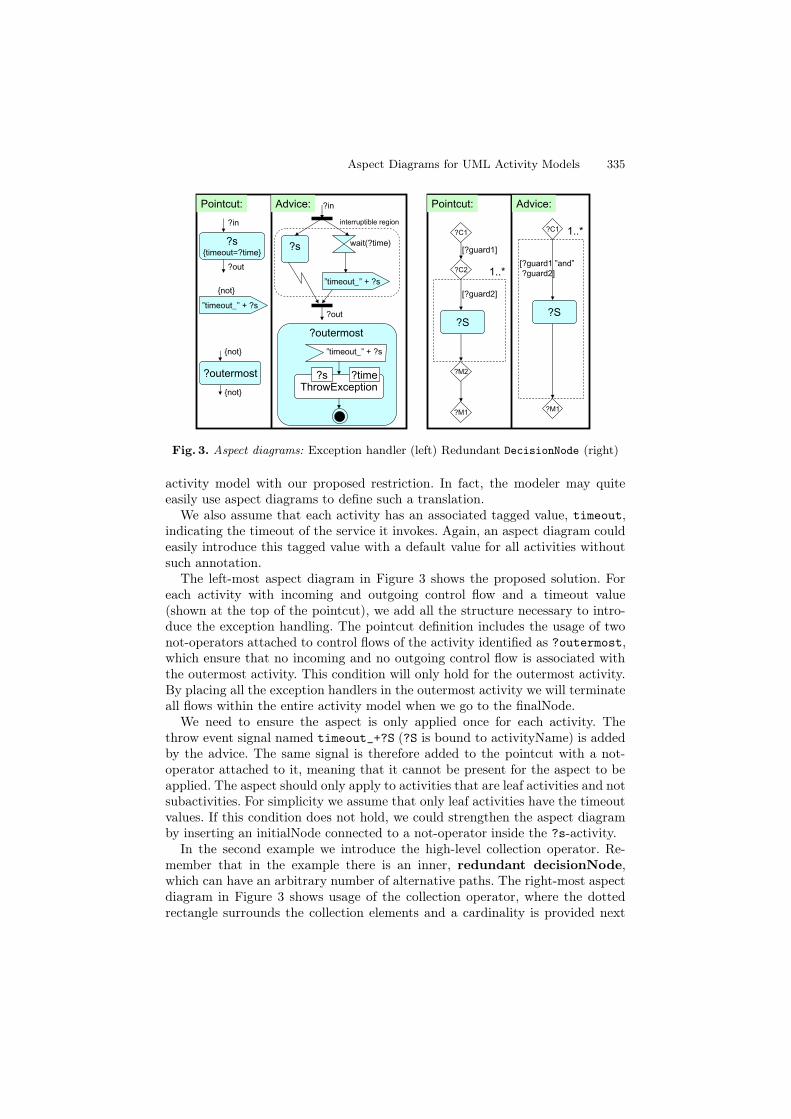
The left-most aspect diagram in Figure 3 shows the proposed solution. Foreach activity with incoming and outgoing control flow and a timeout value(shown at the top of the pointcut), we add all the structure necessary to intro-duce the exception handling. The pointcut definition includes the usage of twonot-operators attached to control flows of the activity identified as ?outermost,which ensure that no incoming and no outgoing control flow is associated withthe outermost activity. This condition will only hold for the outermost activity.By placing all the exception handlers in the outermost activity we will terminateall flows within the entire activity model when we go to the finalNode.
We need to ensure the aspect is only applied once for each activity. Thethrow event signal named timeout_+?S (?S is bound to activityName) is addedby the advice. The same signal is therefore added to the pointcut with a not-operator attached to it, meaning that it cannot be present for the aspect to beapplied. The aspect should only apply to activities that are leaf activities and notsubactivities. For simplicity we assume that only leaf activities have the timeoutvalues. If this condition does not hold, we could strengthen the aspect diagramby inserting an initialNode connected to a not-operator inside the ?s-activity.
In the second example we introduce the high-level collection operator. Re-member that in the example there is an inner, redundant decisionNode,which can have an arbitrary number of alternative paths. The right-most aspectdiagram in Figure 3 shows usage of the collection operator, where the dottedrectangle surrounds the collection elements and a cardinality is provided next
336 R. Grønmo and B. Møller-Pedersen
A
B
A
B
A
B
A
B...
A
B
A A... A
B
A
B
A
B...
a) b) c)pointcuts matches
a) b) c)
Fig. 4. Semantics of the collection operator
to it. The cardinality has the same form as ordinary UML cardinalities. Theelements inside the rectangle of the collection operator indicate that there maybe an arbitrary (cardinality in this case is 1..*) number of matches for this part.Each match however, needs to be linked to the rest of the graph exactly as spec-ified by the relationships to the parts outside of the collection rectangle. Thismeans that the same DecisionNode C2 is linked to all the matches within thecollection operator.
If the collection operator had been extended to include the DecisionNode C2,then we would have had distinct DecisionNodes for all our matches (remem-ber that the matches are injective, which also applies to the collection operatormatches). Identifiers inside the collection pattern denote different elements orproperties for each match, such as the guard in the example. The collection op-erator is normally used also in the advice to indicate the changes to the matchesin the collection. If the collection operator is absent in the advice, it implies arequest to delete all the collection elements. No boolean operators are allowedinside the collection operator. Within this paper we also assume that only asingle collection operator is used within the same aspect diagram. By this weavoid a lot of complexity which we do not have space to cover here.
Figure 4 shows the relationship between the collection operator in the point-cut and possible matches. For the illustration only we use a circle to denotesome element A and B (eg. InitialNode, DecisionNode, JoinNode) that canbe the source or target of a control flow edge. In case a) only the edge is in-side the collection while the source and target elements are outside the col-lection operator. This means that possible matches will have a set of edgesbetween the same A and B elements. In case b) the source A is also insidethe collection which means that a match will contain a set of distinct A ele-ments with edges leading to the same B target element. In case c), both thesource and target is inside the collection, which means that a match will containa set of distinct A and B elements each having their own control flow. We re-quire that a collection match shall be maximal, meaning that the largest set ofelements, limited by the upper bound cardinality, must be gathered before theadvice is applied to the match.
6 Transformation between Concrete and Abstract Syntax
The AGG tool [18] is chosen as the graph transformation tool, and parts of themapping is tailored for this purpose. We need to transform both ways betweenthe concrete syntax of activity models and the abstract syntax of graphs. For
Aspect Diagrams for UML Activity Models 337
this purpose we define a one-to-one correspondence, which is quite straightfor-ward for activity models since they are very close in nature with graph repre-sentation.
Activity, InitialNode, FinalNode, DecisionNode, MergeNode, ForkNode,JoinNode and data objects appear as nodes in the activity model and we chooseto represent these as nodes (with different types) also in the graph representation.The control and data flow edges of activity models are also represented as nodes(with different types), in the graph representation, with two directed outgoingedges labelled src and trg. By this circumstantial mapping of the activity modeledges, missing edge sources or targets, at the concrete syntax, will be translatedinto rules where the source and target of an edge are always present at theabstract syntax. We discuss this further in section 7 after all the transformationrules are presented.
Properties of the different UML types are mapped to node attributes of thecorresponding graph node. An activity name is mapped to a name attributebelonging to the activity graph node, while a control flow guard is mapped toa guard attribute of the control flow graph node. The definition below providesthe one-to-one relation between Activity model and graph representation.
The operator ↔ defines the one-to-one relation between Activity model el-ements and graph elements. It uses an overloaded mapping function φ whichis either φ : Id → Id or φ : Attrs → Attrs, to map from activity elementids/properties to graph ids/attributes. To the left we show the Activity ele-ments and on the right we show the corresponding graph elements. Nodes aregiven by a triple (Id, Type, Attrs) and edges are given by a quintuple (Id, Type,src, trg, Attrs):
The mapping of InitialNode, MergeNode, ForkNode, JoinNode,DecisionNode and FinalNode is similar to the Activity mapping, and themapping of dFlow is similar to the cFlow mapping. ε denotes an empty set ofattributes, Ids are suffixed by Id, and genId() makes a new id. Due to lim-ited space, we do not present a full mapping of the activity models as graphrepresentation within this paper.
We define a one-way transformation from the aspect diagrams to graph trans-formation rules in the abstract syntax. Often a single aspect diagram will bemapped to several graph transformation rules. Since the aspect diagrams aredesigned as extended activity models, the mapping concerning the activity mod-els can follow the mapping defined by ↔. In an aspect diagram without highlevel operators, the pointcut diagram will be mapped to the left part(s) of oneor more graph transformation rule(s), and the advice diagram will be mappedto the right part(s).
338 R. Grønmo and B. Møller-Pedersen
For the property matching and assignment, the identifiers are mapped toAGG identifiers and variables, while Java string expressions can be read directlyby AGG. We omit wildcard expressions (*,?) since it is not supported by AGG.
We need to map the boolean operators of the pointcut language. All ele-ments not explicitly defined as an operand, will implicitly belong to the globaland-operator. This is directly supported by normal graph transformation rules,and no additional mapping is needed.
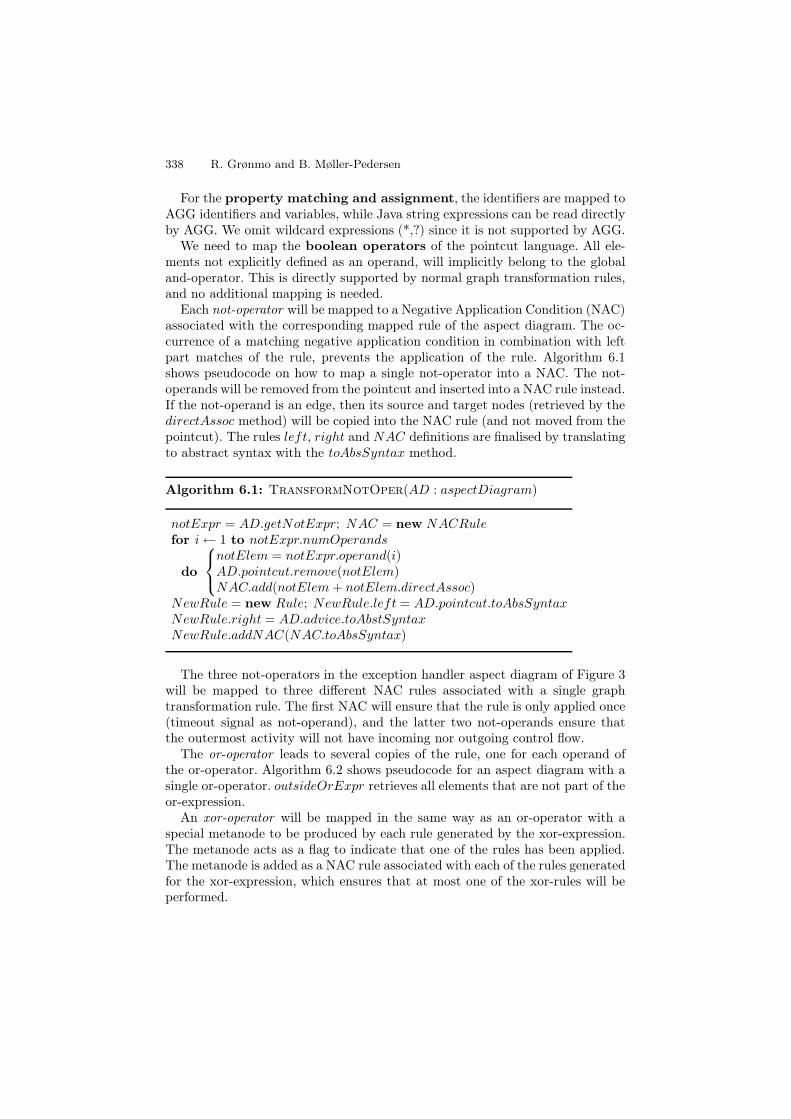
Each not-operator will be mapped to a Negative Application Condition (NAC)associated with the corresponding mapped rule of the aspect diagram. The oc-currence of a matching negative application condition in combination with leftpart matches of the rule, prevents the application of the rule. Algorithm 6.1shows pseudocode on how to map a single not-operator into a NAC. The not-operands will be removed from the pointcut and inserted into a NAC rule instead.If the not-operand is an edge, then its source and target nodes (retrieved by thedirectAssoc method) will be copied into the NAC rule (and not moved from thepointcut). The rules left, right and NAC definitions are finalised by translatingto abstract syntax with the toAbsSyntax method.
NewRule = new Rule; NewRule.left = AD.pointcut.toAbsSyntaxNewRule.right = AD.advice.toAbstSyntaxNewRule.addNAC(NAC.toAbsSyntax)
The three not-operators in the exception handler aspect diagram of Figure 3will be mapped to three different NAC rules associated with a single graphtransformation rule. The first NAC will ensure that the rule is only applied once(timeout signal as not-operand), and the latter two not-operands ensure thatthe outermost activity will not have incoming nor outgoing control flow.
The or-operator leads to several copies of the rule, one for each operand ofthe or-operator. Algorithm 6.2 shows pseudocode for an aspect diagram with asingle or-operator. outsideOrExpr retrieves all elements that are not part of theor-expression.
An xor-operator will be mapped in the same way as an or-operator with aspecial metanode to be produced by each rule generated by the xor-expression.The metanode acts as a flag to indicate that one of the rules has been applied.The metanode is added as a NAC rule associated with each of the rules generatedfor the xor-expression, which ensures that at most one of the xor-rules will beperformed.
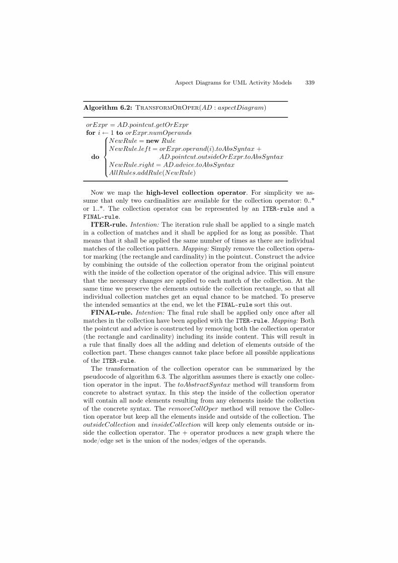
Now we map the high-level collection operator. For simplicity we as-sume that only two cardinalities are available for the collection operator: 0..*or 1..*. The collection operator can be represented by an ITER-rule and aFINAL-rule.
ITER-rule. Intention: The iteration rule shall be applied to a single matchin a collection of matches and it shall be applied for as long as possible. Thatmeans that it shall be applied the same number of times as there are individualmatches of the collection pattern. Mapping: Simply remove the collection opera-tor marking (the rectangle and cardinality) in the pointcut. Construct the adviceby combining the outside of the collection operator from the original pointcutwith the inside of the collection operator of the original advice. This will ensurethat the necessary changes are applied to each match of the collection. At thesame time we preserve the elements outside the collection rectangle, so that allindividual collection matches get an equal chance to be matched. To preservethe intended semantics at the end, we let the FINAL-rule sort this out.
FINAL-rule. Intention: The final rule shall be applied only once after allmatches in the collection have been applied with the ITER-rule. Mapping: Boththe pointcut and advice is constructed by removing both the collection operator(the rectangle and cardinality) including its inside content. This will result ina rule that finally does all the adding and deletion of elements outside of thecollection part. These changes cannot take place before all possible applicationsof the ITER-rule.
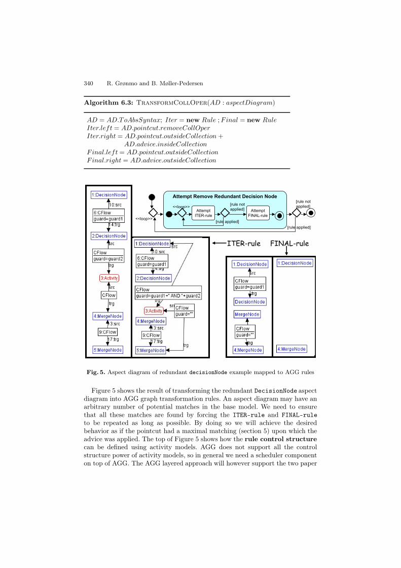
The transformation of the collection operator can be summarized by thepseudocode of algorithm 6.3. The algorithm assumes there is exactly one collec-tion operator in the input. The toAbstractSyntax method will transform fromconcrete to abstract syntax. In this step the inside of the collection operatorwill contain all node elements resulting from any elements inside the collectionof the concrete syntax. The removeCollOper method will remove the Collec-tion operator but keep all the elements inside and outside of the collection. TheoutsideCollection and insideCollection will keep only elements outside or in-side the collection operator. The + operator produces a new graph where thenode/edge set is the union of the nodes/edges of the operands.
Fig. 5. Aspect diagram of redundant decisionNode example mapped to AGG rules
Figure 5 shows the result of transforming the redundant DecisionNode aspectdiagram into AGG graph transformation rules. An aspect diagram may have anarbitrary number of potential matches in the base model. We need to ensurethat all these matches are found by forcing the ITER-rule and FINAL-ruleto be repeated as long as possible. By doing so we will achieve the desiredbehavior as if the pointcut had a maximal matching (section 5) upon which theadvice was applied. The top of Figure 5 shows how the rule control structurecan be defined using activity models. AGG does not support all the controlstructure power of activity models, so in general we need a scheduler componenton top of AGG. The AGG layered approach will however support the two paper
Aspect Diagrams for UML Activity Models 341
examples. Notice that the gluing condition (double-pushout) ensures that theexample FINAL-rule is applied after all corresponding ITER-rule applicationsare finished, but this is not the general case.
7 Discussion
An activity model looks quite like an abstract syntax graph representation withnodes and directed edges, and one could question if the abstract syntax coulddirectly represent the concrete syntax. However, since activity models have el-ements that contain other elements (e.g. subactivity, expansionRegion andinterruptibleRegion), this is not possible. In addition, activity inputPins andoutputPins pose a problem as they have a specialized notation in that they aredisplayed on the border of the owning activity.
Representing control flows as edges also in the abstract syntax would makethings much more difficult. It would not be possible to define a rule withoutthe source or target of a control flow edge. In the aspect diagram, however, weuse explicitly that a missing source or target expresses a wildcard node. With-out this possibility in the exception handler example, we would have to explic-itly express all the different node options to be source of the ?in-labeled edge,and similarly for the target of the ?out-labeled edge. We could at least havethe options of IntialNode/FinalNode (?in/?out), activity, subactivity,ForkNode/JoinNode (?out/?in) and DecisionNode/MergeNode (?out/?in). Tocope with all combinations we would have to make 25 (5x5) different graph trans-formation rules.
An interesting question is to what extent our approach can be generalized: Isthe approach also appropriate for other kinds of models than activity models, sothat we could introduce the same kind of aspect diagrams for UML sequence dia-grams, class diagrams etc.? This remains to be investigated, but an observationis that the closer the modeling language concrete syntax is to a typed attributedlabelled graph, the easier it will be to follow the graph transformation approach.Class diagrams are close to such graphs, while sequence diagrams are differentkinds of graphs. In a mapping from the concrete syntax of a sequence diagraminto an abstract syntax as graphs, we get an explosion in the number of ele-ments. This means that it is highly questionable if the approach, presented inthis paper, is suitable for sequence diagrams.
The property matching, property assignment, boolean operators and rule con-trol structure are general mechanisms and should be applicable to other kindsof models. The generality of high-level operators, and which high-level operatorsare needed, may vary with the kind of model. To achieve an intuitive and easyto comprehend aspect diagram language, we believe it should be tailored to theactual source and target modeling language.
We have developed a proof-of-concept Eclipse GMF-based [3] editor for theaspect diagrams. It currently supports Activity, DecisionNode and MergeNodeof Activity models, in addition to the use of single collection operator, whichwas enough to successfully demonstrate the redundant DecisionNode example.
342 R. Grønmo and B. Møller-Pedersen
The transformation from aspect diagrams to AGG rules has been implementedusing the MOFScript language ([11]). For other examples, including the secondpaper example, we have manually followed the mapping definitions describedbetween abstract and concrete syntax, and tested the graph transformations inAGG upon several base activity models with successful results.
8 Related Work
Several approaches (QVT [13], Zhang et al. [20], graph transformation approachessuch as AGG [18], Ehrig et al. [4] and PROGRESS [15]) provide model transfor-mation languages and tools that can define transformations between generalsource and target modeling languages, and where one transformation may oper-ate on different source and target modeling languages. In cases where the sourceand target languages are both activity models, they suffer from using abstractsyntax instead of the more intuitive concrete syntax on which our aspect dia-grams are defined.
Lindqvist et al. [9] propose the star operator which can be used in a point-cut language to find repetitive occurrences of a specific modeling pattern andis complementary to our collection operator. The star operator is limited torepetitive occurrences that constitute a sequential path, and is thus not strongenough to model the collection operator. It is only proposed within a pure querypart (like our pointcut), and has no associated advice part as we have defined.Furthermore, the star operator is presented on abstract syntax only. However,the authors share our opinion with respect to concrete syntax: In a tool envi-ronment, however, creating the queries using the concrete syntax of the modelinglanguage can be beneficial.
Aspect-oriented behavior modeling approaches so far have been dominated byUML sequence diagram attempts [19] [1] [2] [17]. Solberg et al. [8] and Whittleand Araújo [19] perform weaving at the model level as in our approach. Deubleret al. [2] and Stein et al. [17] use sequence diagrams to model the aspects ata conceptual level to be mapped to some aspect programming language suchas AspectJ [7]. Stein et al. [17] focus only on the conceptual modeling of thepointcut, and do not cover advice modeling.
Klein et al. [8] propose semantic-based weaving of Hierarchical Message Se-quence Charts (close to UML sequence diagrams). Their approach focuses on theweaving algorithm that takes the execution semantics into account in the weav-ing process. This is a benefit compared to our approach since the aspect diagramsand the graph transformation system performs pure syntax-based weaving. Toillustrate the aspect definition, they provide an example of a pointcut and advicewhich is similar to the graph transformation principle aspect diagrams are builtupon. However, the aspect definition given only explains the example, and nofurther attempt to define an aspect-oriented modeling specification language isgiven.
Mehner et al. [10] analyzes if a set of aspects may be properly woven withthe base model by considering possible conflicts and dependencies. Pre- and
Aspect Diagrams for UML Activity Models 343
post-conditions expresses the effects of each activity in the AGG tool whereautomated analysis is carried out. The aspect definitions proposed in their paperare limited to inserting an entire new use case before, after or as a replacementof some previous activity. None of our two example aspects are expressible withthis definition.
9 Conclusions and Future Work
We have proposed activity aspect diagrams as a way to define aspects uponactivity models. The approach is built upon transformation of both activity -and activity aspect diagrams in concrete syntax to an abstract syntax of a graphtransformation tool, which then performs the weaving. A major benefit is thatthe aspect modeler can operate directly within the familiar syntax of activitymodels instead of the more general graph transformation rules of traditionalgraph transformation approaches. At the same time we can benefit from analysisof confluence and termination in the graph transformation tool.
Transformation approaches have been dominated by textual languages, eventhough the source and target languages may be graphical languages. One rea-son is that textual programming languages have been widely used for decadeswith lots of practical experience and improvements. While the earlier attemptsused low-level, non-comprehensible constructs, todays textual programming lan-guages use several high-level constructs (eg. while-loops, inheritance, recursion)to allow for user-friendly programming. By introducing high-level operators alsofor graphical transformation languages, we believe that the graphical languagescan learn from the history of textual programming language development. Onesuch high-level operator, the collection operator, has been introduced in thispaper to demonstrate the principle.
As future work we may look into nested collection operators, and investi-gate more practical examples to see if we need additional high-level operators.We would also like to explore the relationship between termination and conflu-ence criteria at the concrete vs. the abstract representation of the transformationrules.
Acknowledgment. The work reported in this paper has been funded by TheResearch Council of Norway, grant no. 167172/V30 (the SWAT project).
References
1. Clarke, S., Walker, R.J.: Composition Patterns: An Approach to DesigningReusable Aspects. In: Proceedings of the 23rd International Conference on SoftwareEngineering (ICSE), Toronto, Ontario, Canada (2001)
2. Deubler, M., Meisinger, M., Rittmann, S., Krüger, I.: Modeling Crosscutting Ser-vices with UML Sequence Diagrams. In: Briand, L.C., Williams, C. (eds.) MoDELS2005. LNCS, vol. 3713, pp. 522–536. Springer, Heidelberg (2005)
4. Ehrig, K., Ermel, C., Hänsgen, S.: Towards Model Transformation in GeneratedEclipse Editor Plug-Ins. Electr. Notes Theor. Comput. Sci. 152, 39–52 (2006)
5. Grønmo, R., Jaeger, M.C.: Model-Driven Methodology for Building QoS-OptimisedWeb Service Compositions. In: Kutvonen, L., Alonistioti, N. (eds.) DAIS 2005.LNCS, vol. 3543, pp. 68–82. Springer, Heidelberg (2005)
6. Eder, J., Gruber, W., Pichler, H.: Transforming Workflow Graphs. In: Proceedingsof the First International Conference on Interoperability of Enterprise Softwareand Applications (INTEROP-ESA 2005), Geneva, Switzerland (February 2005)
7. Kiczales, G., Hilsdale, E., Hugunin, J., Kersten, M., Palm, J., Griswold, W.G.:An Overview of AspectJ. In: Knudsen, J.L. (ed.) ECOOP 2001. LNCS, vol. 2072.Springer, Heidelberg (2001)
8. Klein, J., Hélouët, L., Jézéquel, J.-M.: Semantic-based weaving of scenarios. In:Proceedings of the 5th International Conference on Aspect-Oriented Software De-velopment, Bonn, Germany (2006)
9. Lindqvist, J., Lundkvist, T., Porres, I.: A Query Language With the Star Operator.In: Proceedings of the 6th International Workshop on Graph Transformation andVisual Modeling Techniques, Braga, Portugal (April 2007)
10. Mehner, K., Monga, M., Taentzer, G.: Interaction Analysis in Aspect-OrientedModels. In: 14th IEEE International Conference on Requirements Engineering (RE2006), Minneapolis/St.Paul, Minnesota, USA (2006)
11. Oldevik, J., Neple, T., Grønmo, R., Aagedal, J.Ø., Berre, A.-J.: Toward standard-ised model to text transformations. In: Hartman, A., Kreische, D. (eds.) ECMDA-FA 2005. LNCS, vol. 3748, pp. 239–253. Springer, Heidelberg (2005)
14. Tatte, S. (ed.): Business Process Execution Language for Web Services Version 1.1(February 2005)
15. Schürr, A.: Introduction to PROGRESS, an Attribute Graph Grammar BasedSpecification Language. In: Nagl, M. (ed.) WG 1989. LNCS, vol. 411. Springer,Heidelberg (1989)
16. Skogan, D., Grønmo, R., Solheim, I.: Web Service Composition in UML. In: Pro-ceedings of the 8th IEEE Intl Enterprise Distributed Object Computing Conf(EDOC 2004), Monterey, California (September 2004)
17. Stein, D., Hanenberg, S., Unland, R.: Join Point Designation Diagrams: a Graphi-cal Representation of Join Point Selections. International Journal of Software En-gineering and Knowledge Engineering 16(3), 317–346 (2006)
18. Taentzer, G.: AGG: A Graph Transformation Environment for Modeling and Val-idation of Software. In: Pfaltz, J.L., Nagl, M., Böhlen, B. (eds.) AGTIVE 2003.LNCS, vol. 3062, pp. 446–453. Springer, Heidelberg (2004)