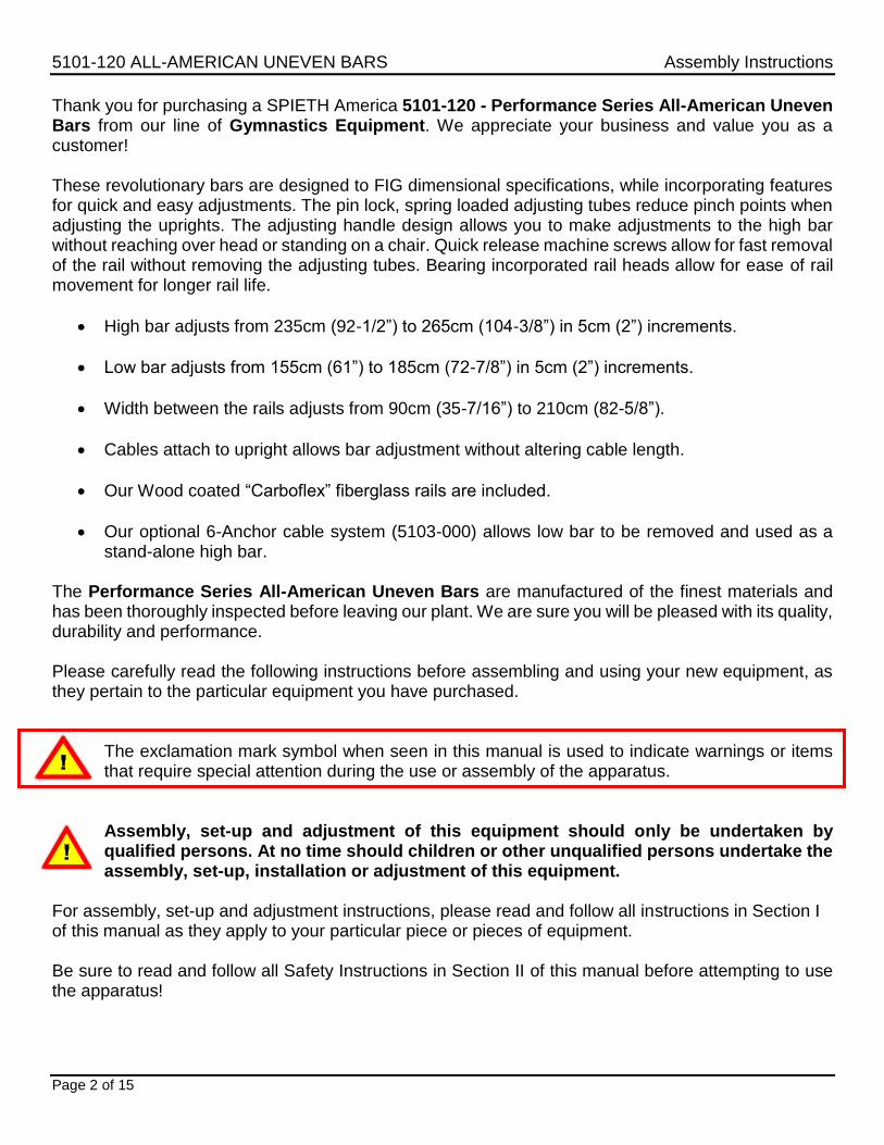
Thank you for purchasing a SPIETH America 5101-120 - Performance Series All-American Uneven Bars from our line of Gymnastics Equipment. We appreciate your business and value you as a customer! These revolutionary bars are designed to FIG dimensional specifications, while incorporating features for quick and easy adjustments. The pin lock, spring loaded adjusting tubes reduce pinch points when adjusting the uprights. The adjusting handle design allows you to make adjustments to the high bar without reaching over head or standing on a chair. Quick release machine screws allow for fast removal of the rail without removing the adjusting tubes. Bearing incorporated rail heads allow for ease of rail movement for longer rail life.
High bar adjusts from 235cm (92-1/2”) to 265cm (104-3/8”) in 5cm (2”) increments.
Low bar adjusts from 155cm (61”) to 185cm (72-7/8”) in 5cm (2”) increments.
Width between the rails adjusts from 90cm (35-7/16”) to 210cm (82-5/8”).
Cables attach to upright allows bar adjustment without altering cable length.
Our Wood coated “Carboflex” fiberglass rails are included.
Our optional 6-Anchor cable system (5103-000) allows low bar to be removed and used as a stand-alone high bar.
The Performance Series All-American Uneven Bars are manufactured of the finest materials and has been thoroughly inspected before leaving our plant. We are sure you will be pleased with its quality, durability and performance. Please carefully read the following instructions before assembling and using your new equipment, as they pertain to the particular equipment you have purchased.
The exclamation mark symbol when seen in this manual is used to indicate warnings or items that require special attention during the use or assembly of the apparatus.
Assembly, set-up and adjustment of this equipment should only be undertaken by qualified persons. At no time should children or other unqualified persons undertake the assembly, set-up, installation or adjustment of this equipment.
For assembly, set-up and adjustment instructions, please read and follow all instructions in Section I of this manual as they apply to your particular piece or pieces of equipment. Be sure to read and follow all Safety Instructions in Section II of this manual before attempting to use the apparatus!
When handling the Short and Long Upright assemblies, never release the Spin-Lock & pull out the Snap-Lock when in a horizontal position or when the Uprights are not assembled to a rail in the vertical position! Serious personal injury or damage to the Adjusting Tubes and Uprights will occur! Uprights are shipped set and locked in their lowest height settings to make assembly as easy as possible, so no height adjustment is required until after the rails are installed. See section on Height Adjustment of Uprights before attempting to adjust the height of the Adjusting Tubes.
The 5101-120 - Performance Series All-American Uneven Bars consist of:
Two (2) Uneven Bar Bases, assembled complete with shoulder bushings (4 per base), Axle Bolts (2 per base), Hex Lock nuts (2 per base) and with anchoring hardware
Two (2) pre-assembled All-American Width Adjusters
Two (2) pre-assembled Short Uprights
Two (2) pre-assembled Long Uprights (1 right & 1 left)
Two (2) Fiberglass rails.
One (1) complete tie-down system including four (4) Chain & Turnbuckle Assemblies, four (4) Cables & Cable Tensioners with Pulley Assemblies and four (4) threaded Socket Adapter #184B.
4 Concrete Floor anchors are required for securing the Threaded Socket Adaptors. These floor anchors are not supplied with this package. They must be purchased separately. Concrete anchors are available at SPIETH America under spare part #PEA1 (Set of 4 pieces).
1.2. Preparation to Assembly To complete the assembly of your 5101-120 All-American Uneven Bars, you will require two (2) 1/2” Wrenches, one (1) 5/16” Open End Wrench (adjustable wrenches can also be used), one (1) 3/8” Allen Wrench, and a screw driver.
The assembly and set-up of this apparatus requires three to five (3 to 5) qualified persons. Do not attempt the assembly and set-up of this apparatus alone! Installing the concrete anchors properly is critical for this apparatus to function safely!
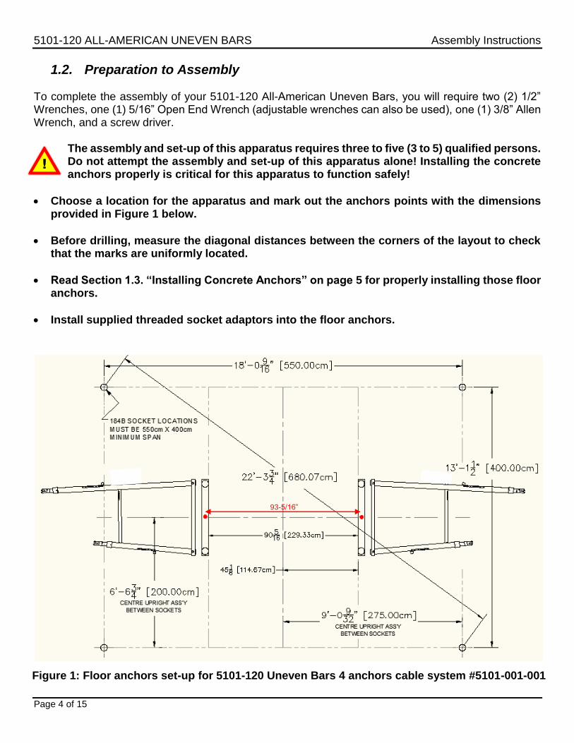
Choose a location for the apparatus and mark out the anchors points with the dimensions provided in Figure 1 below.
Before drilling, measure the diagonal distances between the corners of the layout to check that the marks are uniformly located.
Read Section 1.3. “Installing Concrete Anchors” on page 5 for properly installing those floor anchors.
Install supplied threaded socket adaptors into the floor anchors.
Figure 1: Floor anchors set-up for 5101-120 Uneven Bars 4 anchors cable system #5101-001-001
To determine anchor locations, please refer to the following section for your specific equipment to be anchored.
Tools Required (customer supplied):
Tape measure
Anchor setting tool or punch with a 5/16” diameter & 1.5” long end
5/8” diameter carbide tipped concrete drill bit
Hammer drill
¾” or 19mm Socket, Extension and Ratchet
Hammer
Safety glasses
Never place a floor anchor into a seam/crack, or an area within 9” from a seam/crack or outside edge of the concrete floor
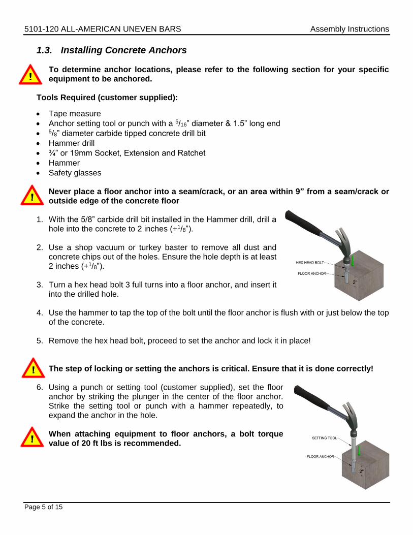
1. With the 5/8” carbide drill bit installed in the Hammer drill, drill a
hole into the concrete to 2 inches (+1/8”). 2. Use a shop vacuum or turkey baster to remove all dust and
concrete chips out of the holes. Ensure the hole depth is at least 2 inches (+1/8”).
3. Turn a hex head bolt 3 full turns into a floor anchor, and insert it
into the drilled hole. 4. Use the hammer to tap the top of the bolt until the floor anchor is flush with or just below the top
of the concrete. 5. Remove the hex head bolt, proceed to set the anchor and lock it in place!
The step of locking or setting the anchors is critical. Ensure that it is done correctly!
6. Using a punch or setting tool (customer supplied), set the floor anchor by striking the plunger in the center of the floor anchor. Strike the setting tool or punch with a hammer repeatedly, to expand the anchor in the hole.
When attaching equipment to floor anchors, a bolt torque value of 20 ft lbs is recommended.
Mount the width adjusters on the Uprights and assemble the Long and Short Uprights into one of the bases. To avoid losing parts, work with one base at a time.
1. Unscrew the Allen bolt at the bottom of one short upright and one long upright (see in Figure 2
below).
2. Insert one width adjuster assembly over the two uprights (short and long). Make sure all the T-
Handles are facing the same way, and that the high upright height adjustment handle is
facing outward. Adjust both Width Adjusters to the 180 cm setting (F.I.G. setting), by aligning each top edge of the sliding sleeve of the width adjuster, to the “F” mark on the uprights. Tighten both width adjuster tightening handles so the assembly is safe and the width adjuster cannot
move along the uprights anymore. Screw back the Allen bolts in their threaded hole on each
upright. Ensure the width adjusters tightening handles are securely tightened before going to the next step.
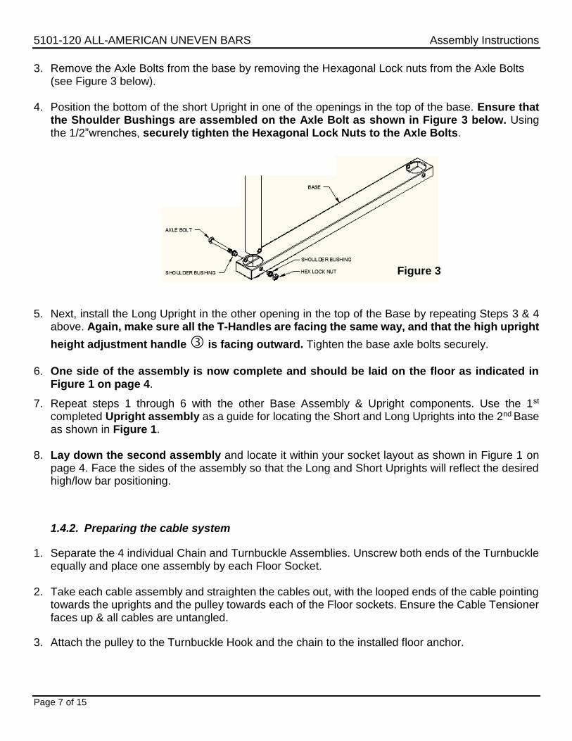
3. Remove the Axle Bolts from the base by removing the Hexagonal Lock nuts from the Axle Bolts (see Figure 3 below).
4. Position the bottom of the short Upright in one of the openings in the top of the base. Ensure that
the Shoulder Bushings are assembled on the Axle Bolt as shown in Figure 3 below. Using the 1/2”wrenches, securely tighten the Hexagonal Lock Nuts to the Axle Bolts.
5. Next, install the Long Upright in the other opening in the top of the Base by repeating Steps 3 & 4
above. Again, make sure all the T-Handles are facing the same way, and that the high upright
height adjustment handle is facing outward. Tighten the base axle bolts securely.
6. One side of the assembly is now complete and should be laid on the floor as indicated in
Figure 1 on page 4.
7. Repeat steps 1 through 6 with the other Base Assembly & Upright components. Use the 1st completed Upright assembly as a guide for locating the Short and Long Uprights into the 2nd Base as shown in Figure 1.
8. Lay down the second assembly and locate it within your socket layout as shown in Figure 1 on
page 4. Face the sides of the assembly so that the Long and Short Uprights will reflect the desired high/low bar positioning.
1.4.2. Preparing the cable system
1. Separate the 4 individual Chain and Turnbuckle Assemblies. Unscrew both ends of the Turnbuckle equally and place one assembly by each Floor Socket.
2. Take each cable assembly and straighten the cables out, with the looped ends of the cable pointing
towards the uprights and the pulley towards each of the Floor sockets. Ensure the Cable Tensioner faces up & all cables are untangled.
3. Attach the pulley to the Turnbuckle Hook and the chain to the installed floor anchor.
The assembly and set-up of this apparatus requires three to five (3 to 5) qualified persons. Do not attempt the assembly and set-up of this apparatus alone! 2 persons per side and one person to install the rail are suggested.
Keep in mind that the assembly is not stable at this point and that each side must be supported at all times during the installation.
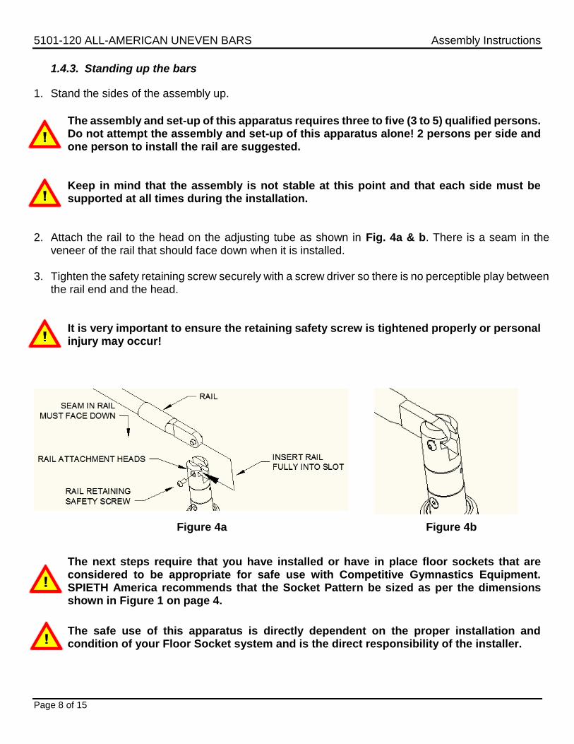
2. Attach the rail to the head on the adjusting tube as shown in Fig. 4a & b. There is a seam in the
veneer of the rail that should face down when it is installed.
3. Tighten the safety retaining screw securely with a screw driver so there is no perceptible play between the rail end and the head.
It is very important to ensure the retaining safety screw is tightened properly or personal injury may occur!
The next steps require that you have installed or have in place floor sockets that are considered to be appropriate for safe use with Competitive Gymnastics Equipment. SPIETH America recommends that the Socket Pattern be sized as per the dimensions shown in Figure 1 on page 4.
The safe use of this apparatus is directly dependent on the proper installation and condition of your Floor Socket system and is the direct responsibility of the installer.
4. The tie-down system (Cables) can now be assembled.
The Pulley end of the Cable assembly should be hooked into the Turnbuckle Hook and the Chain hooked to a floor socket.
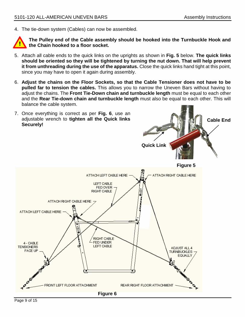
5. Attach all cable ends to the quick links on the uprights as shown in Fig. 5 below. The quick links should be oriented so they will be tightened by turning the nut down. That will help prevent it from unthreading during the use of the apparatus. Close the quick links hand tight at this point, since you may have to open it again during assembly.
6. Adjust the chains on the Floor Sockets, so that the Cable Tensioner does not have to be pulled far to tension the cables. This allows you to narrow the Uneven Bars without having to adjust the chains. The Front Tie-Down chain and turnbuckle length must be equal to each other and the Rear Tie-down chain and turnbuckle length must also be equal to each other. This will balance the cable system.
7. Once everything is correct as per Fig. 6, use an adjustable wrench to tighten all the Quick links Securely!
Never tighten a Turnbuckle or Load Binder with any leverage tool. Over-tightening may result in personal injury or damage to the apparatus.
When tightening the cables, be aware that the Cable Tensioners will move rapidly backwards down the cable if they are not securely locked in place. ALWAYS KEEP A FIRM GRIP ON THE HANDLE WHEN TIGHTENING THE CABLES OR WHEN LOOSENING THE SPIN-LOCK TO RELEASE TENSION, SINCE PERSONAL INJURY CAN OCCUR if the tensioner is not controlled. Never let go of the handle until the tensioner is securely locked in place using the spin-lock.
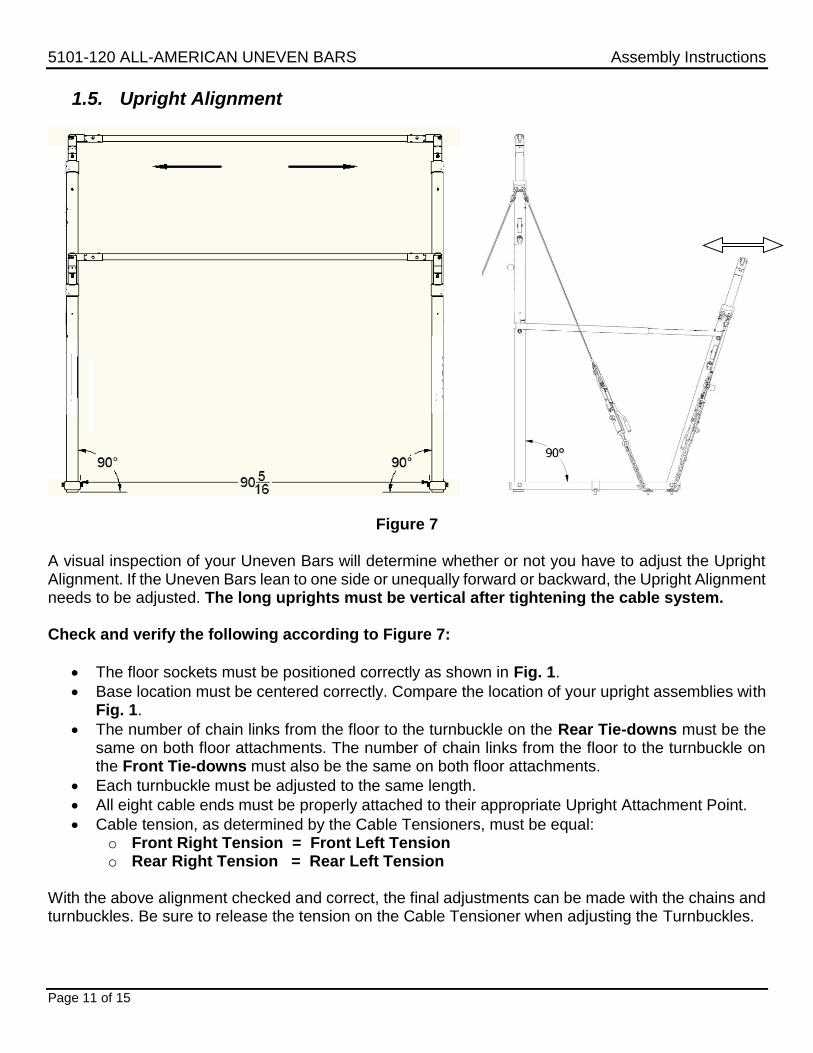
Figure 7 A visual inspection of your Uneven Bars will determine whether or not you have to adjust the Upright Alignment. If the Uneven Bars lean to one side or unequally forward or backward, the Upright Alignment needs to be adjusted. The long uprights must be vertical after tightening the cable system. Check and verify the following according to Figure 7:
The floor sockets must be positioned correctly as shown in Fig. 1.
Base location must be centered correctly. Compare the location of your upright assemblies with Fig. 1.
The number of chain links from the floor to the turnbuckle on the Rear Tie-downs must be the same on both floor attachments. The number of chain links from the floor to the turnbuckle on the Front Tie-downs must also be the same on both floor attachments.
Each turnbuckle must be adjusted to the same length.
All eight cable ends must be properly attached to their appropriate Upright Attachment Point.
Cable tension, as determined by the Cable Tensioners, must be equal: o Front Right Tension = Front Left Tension o Rear Right Tension = Rear Left Tension
With the above alignment checked and correct, the final adjustments can be made with the chains and turnbuckles. Be sure to release the tension on the Cable Tensioner when adjusting the Turnbuckles.
When a single turnbuckle is adjusted, the whole apparatus will be pulled toward or away from that corner. Equal adjustments undertaken at all turnbuckles will avoid any misalignment. Avoid tightening a turnbuckle with any leverage tool. Over-tightening can result in possible damage to the apparatus.
Never adjust the Width Adjusters without releasing the tension on the Tie-down System, or severe damage will result to Width Adjusters, Uprights and components.
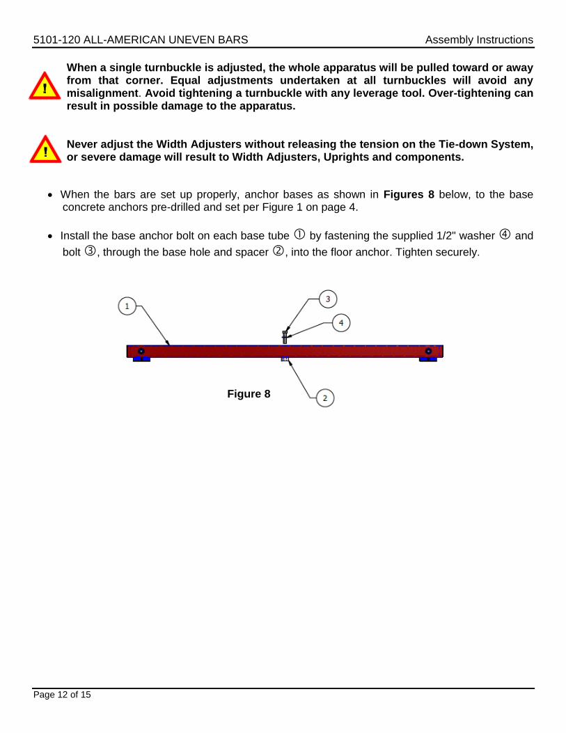
When the bars are set up properly, anchor bases as shown in Figures 8 below, to the base concrete anchors pre-drilled and set per Figure 1 on page 4.
Install the base anchor bolt on each base tube by fastening the supplied 1/2" washer and
bolt , through the base hole and spacer , into the floor anchor. Tighten securely.
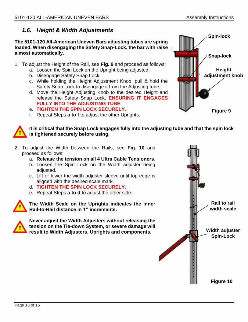
1.6. Height & Width Adjustments The 5101-120 All-American Uneven Bars adjusting tubes are spring loaded. When disengaging the Safety Snap-Lock, the bar with raise almost automatically. 1. To adjust the Height of the Rail, see Fig. 9 and proceed as follows:
a. Loosen the Spin Lock on the Upright being adjusted. b. Disengage Safety Snap Lock. c. While holding the Height Adjustment Knob, pull & hold the
Safety Snap Lock to disengage it from the Adjusting tube. d. Move the Height Adjusting Knob to the desired Height and
release the Safety Snap Lock, ENSURING IT ENGAGES FULLY INTO THE ADJUSTING TUBE.
e. TIGHTEN THE SPIN LOCK SECURELY. f. Repeat Steps a to f to adjust the other Uprights.
It is critical that the Snap Lock engages fully into the adjusting tube and that the spin lock is tightened securely before using.
2. To adjust the Width between the Rails, see Fig. 10 and
proceed as follows: a. Release the tension on all 4 Ultra Cable Tensioners. b. Loosen the Spin Lock on the Width adjuster being
adjusted. c. Lift or lower the width adjuster sleeve until top edge is
aligned with the desired scale mark. d. TIGHTEN THE SPIN LOCK SECURELY. e. Repeat Steps a to d to adjust the other side.
The Width Scale on the Uprights indicates the inner Rail-to-Rail distance in 1” increments.
Never adjust the Width Adjusters without releasing the tension on the Tie-down System, or severe damage will result to Width Adjusters, Uprights and components.
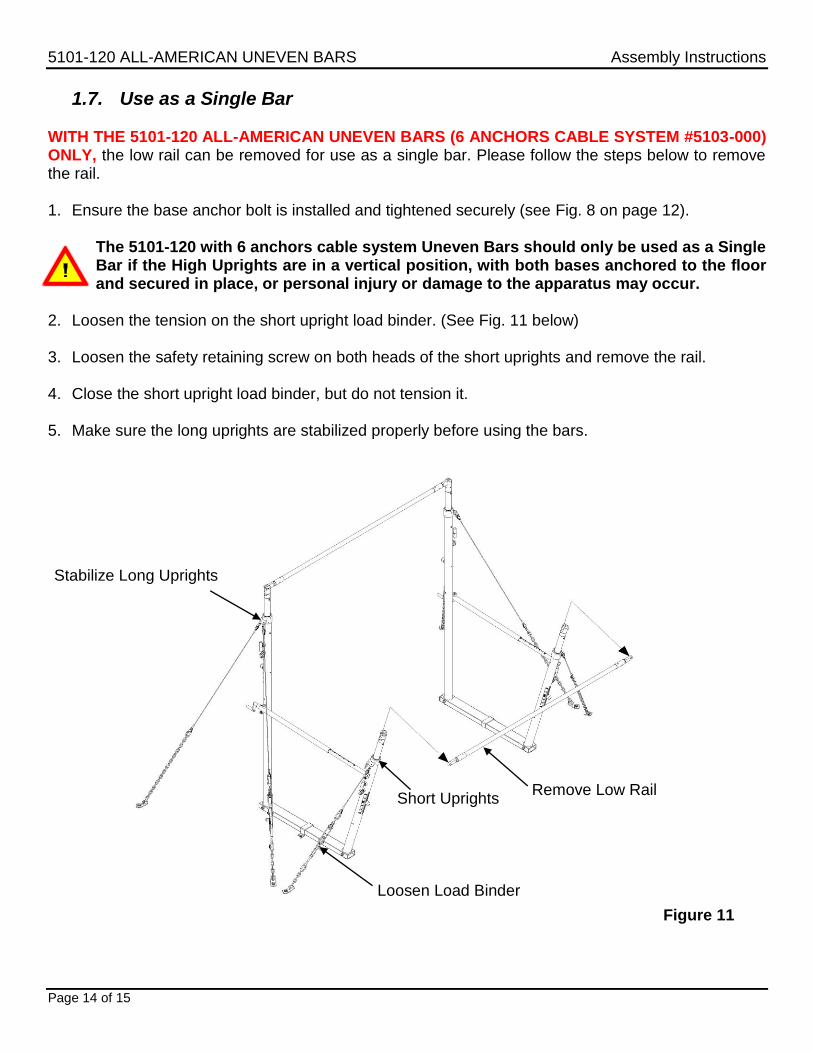
1.7. Use as a Single Bar WITH THE 5101-120 ALL-AMERICAN UNEVEN BARS (6 ANCHORS CABLE SYSTEM #5103-000) ONLY, the low rail can be removed for use as a single bar. Please follow the steps below to remove the rail. 1. Ensure the base anchor bolt is installed and tightened securely (see Fig. 8 on page 12).
The 5101-120 with 6 anchors cable system Uneven Bars should only be used as a Single Bar if the High Uprights are in a vertical position, with both bases anchored to the floor and secured in place, or personal injury or damage to the apparatus may occur.
2. Loosen the tension on the short upright load binder. (See Fig. 11 below)
3. Loosen the safety retaining screw on both heads of the short uprights and remove the rail.
4. Close the short upright load binder, but do not tension it.
5. Make sure the long uprights are stabilized properly before using the bars.
WARNING Any activity involving motion or height creates the possibility of serious injury including permanent paralysis and even death, from landing or falling on the neck, head, or other parts of the body. You assume a risk of serious injury in using this equipment. However, this risk can be reduced by strictly following these rules at all times. 1. Use this equipment only under the supervision of a trained and qualified instructor. 2. This equipment must be used only when protected by proper matting as recommended by the
Federation of International Gymnasts (F.I.G.). If in doubt concerning proper matting, do not use this equipment.
3. This equipment must be used with proper spotting equipment and qualified spotters suitable
to the activity or skill. Always consult an instructor. 4. Know your own limitations and the limitations of this equipment. Follow progressive learning
techniques and always consult an instructor. 5. Always inspect this equipment for proper stability before each use. 6. Always inspect this equipment for loose fittings and parts. Replace any worn, defective or
missing parts. 7. Always inspect this equipment for improper or unsafe installation. If in doubt, do not use