Reproduction, duplication or translation, also in extracts, without the written approval ofSorotec GmbH is not permitted. All rights under the Copyright Act remain theSorotec GmbH expressly reserved.
Technical changes reserved.Made in Germany.
Page 3/24
Assembly instructions Hobby-Line 10560 kit
www.sorotec.de V 1.2.1
IntroductionCongratulations on the purchase of our kit for a Hob-by-Line CNC portal milling machine. We recommend reading through these instructions completely before assembly and then assembling the kit step by step as described.
Required toolsWhen designing the Hobby Line, care was taken to ensure that no special tools are required for assem-bly. However, common hand tools such as wren-ches, Allen keys, screwdrivers, plastic hammers, etc. should be available. A work surface that is as flat as possible and the size of the base frame is also a pre-requisite for a successful construction.
Required accessoriesThree stepper or servo motors the size of NEMA 23 for the axis drives. The motors are an integral part of the design and indispensable for the sensible cons-truction of the portal milling machine. If not yet procu-red, you will find suitable motors in the Sorotec shop:
http://www.sorotec.de/shop/index.php
Optional accessoriesThe fully assembled machine can be supplemented and adapted to your requirements with optional ac-cessories. In the Sorotec shop you will find:
• Milling spindles• Electric mounting kit• Control electronics• Control software• T-slot plate• Vacuum table• Minimum quantity lubrication• Vacuum chip disposal• Enclosure
Attention!Only carry out the work if you are familiar with the ne-cessary actions and do have suitable tools available.
Sorotec GmbH assumes no responsibility or liability for damage to property or personal injury that occurs during the assembly or operation of the CNC portal milling machine.
General informationPlease assemble the kit as carefully and precisely as possible - the accuracy of the finished machine not only depends on the quality of the components supplied, but also to a large extent on the correct as-sembly and precise alignment. All components must be checked for burrs before assembly and reworked if necessary.
Page 4/24
Assembly instructions Hobby-Line 10560 kit
www.sorotec.de V 1.2.1
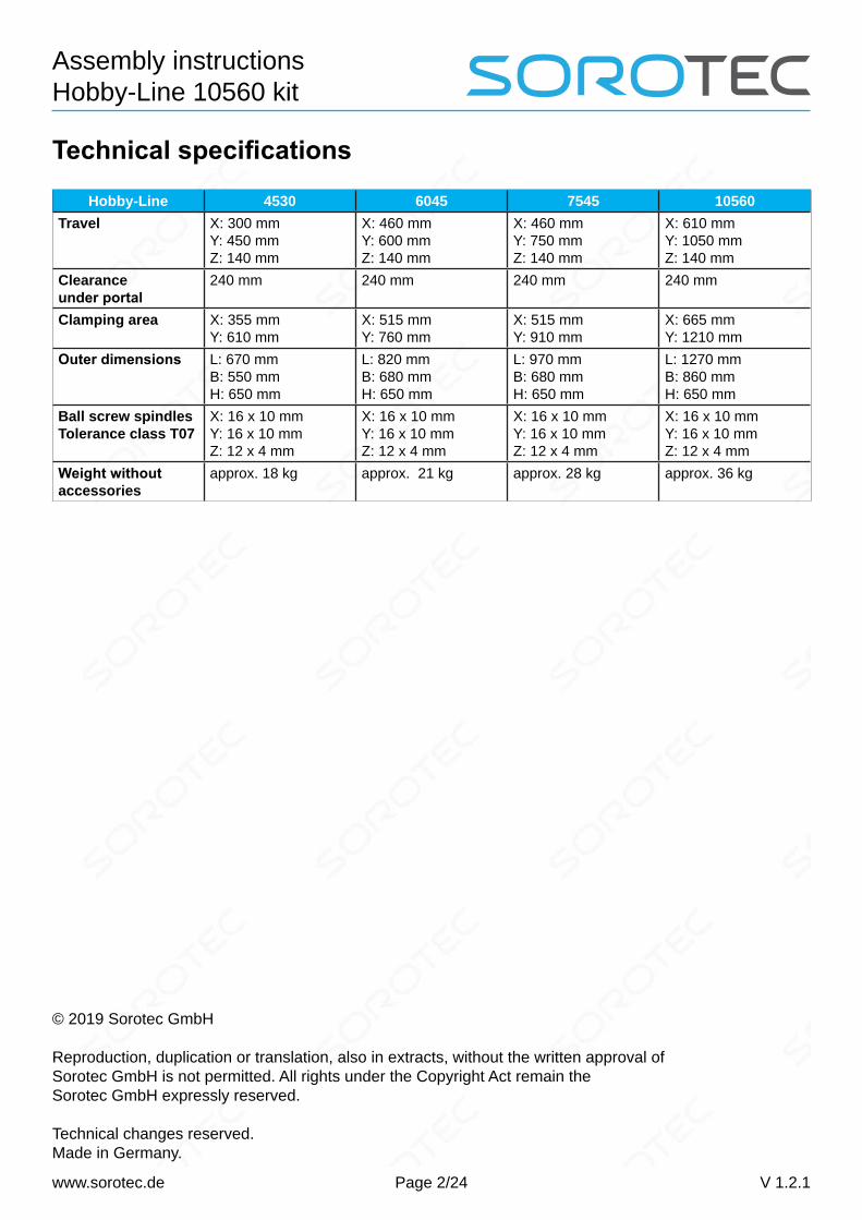
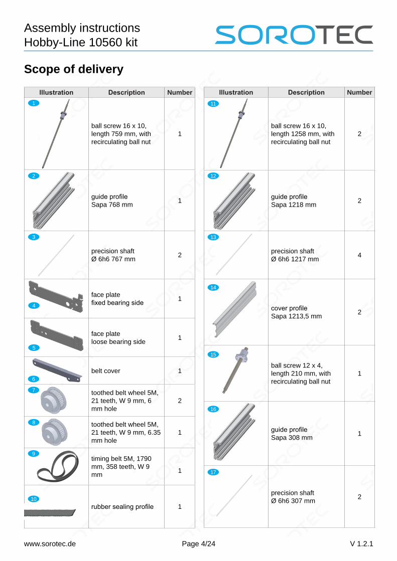
Scope of delivery
Illustration Description Number
ball screw 16 x 10, length 759 mm, with recirculating ball nut
1
guide profile Sapa 768 mm 1
precision shaft Ø 6h6 767 mm 2
face platefixed bearing side 1
face plate loose bearing side 1
belt cover 1
toothed belt wheel 5M, 21 teeth, W 9 mm, 6 mm hole
2
toothed belt wheel 5M, 21 teeth, W 9 mm, 6.35 mm hole
1
timing belt 5M, 1790 mm, 358 teeth, W 9 mm
1
rubber sealing profile 1
1
2
3
4
5
8
Illustration Description Number
ball screw 16 x 10, length 1258 mm, with recirculating ball nut
2
guide profile Sapa 1218 mm 2
precision shaft Ø 6h6 1217 mm 4
cover profile Sapa 1213,5 mm 2
ball screw 12 x 4, length 210 mm, with recirculating ball nut
1
guide profile Sapa 308 mm 1
precision shaft Ø 6h6 307 mm 2
11
12
13
14
15
16
17
6
7
9
10
Page 5/24
Assembly instructions Hobby-Line 10560 kit
www.sorotec.de V 1.2.1
Illustration Description Number
motor plate Z 1
end plate Z 1
right portal plate (loose bearing side) 1
left portal plate (driving side) 1
sled 1
nut block table / portal for 16 spindle 3
nut block Z axisfor 12 spindle 1
reference switchbracket X and Y 2
reference switchbracket X 1
18
19
20
21
22
23
24
25
26
Illustration Description Number
drag chain anglefor portal 1
bracket forconnector 1
bracket angledfor plug connection 2
reference switchcasing 3
reference switch 3
drag chain 1 m 18 x 25 mm 3
connector kit for drag chain 18 x 25 mm 2
mounting bracket fordrag chain 1
cable tie block 6-20 6
reference angle Z 1
locating screw DIN 7379 M6 x 25
1
adjusting washer DIN 988 8 x 14 x 0,2 mm
2
miniatureflange ball bearing 8 x 22 x 7 mm
2
27
28
29
30
RS
31
32
33
34
35
36
37
38
Page 6/24
Assembly instructions Hobby-Line 10560 kit
www.sorotec.de V 1.2.1
Illustration Description Number
fixed bearingretaining plate 4 mm 2
fixed bearingspacer plate 2 mm 2
fixed bearing seat 2
fixed bearing spacer sleeve 8 x 12 x 5 mm 2
coupling 2
min.-ball bearing 688 2RS 8 x 16 x 5 mm 4
min.-ball bearing R4 2RS 6,35 x 15,875 x 4,978 mm
2
sleeve bearing M250 Iglidur 3
adjusting washer DIN 988 10 x 16 x 1,2 mm
2
centricroller guide 8
eccentricroller guide 8
castor LFR50/8-6.2RS 16
39
40
41
42
43
44
45
46
47
48
49
50
Illustration Description Number
flat nut M8 x 0,75 for exc. roller guide
Fine thread!8
adjusting washer DIN 988 8 x 14 x 1 mm
48
table profile 20 x 20 mm Typ B, Länge 1217 mm
2
table profile 20 x 20 mm Typ B, Länge 632 mm
6
emergency stop 30 mm 1-pole / bore 16 mm 1
washer Ø M8 galvanized, large 2
washer Ø M6 galvanized, large
14
washer Ø M4 galvanized, large 3
nut DIN 934 59 M4 60 M6
3 4
DIN 985 M6, self-locking nut 1
DIN 985 M8 x 1, self-locking nut
Fine thread!2
DIN 985 M8, self-locking nut 16
angle 5 20 x 20 mm 20
51
52
53
54
55
59
57
58
61
62
63
64
Page 7/24
Assembly instructions Hobby-Line 10560 kit
www.sorotec.de V 1.2.1
Illustration Description Number
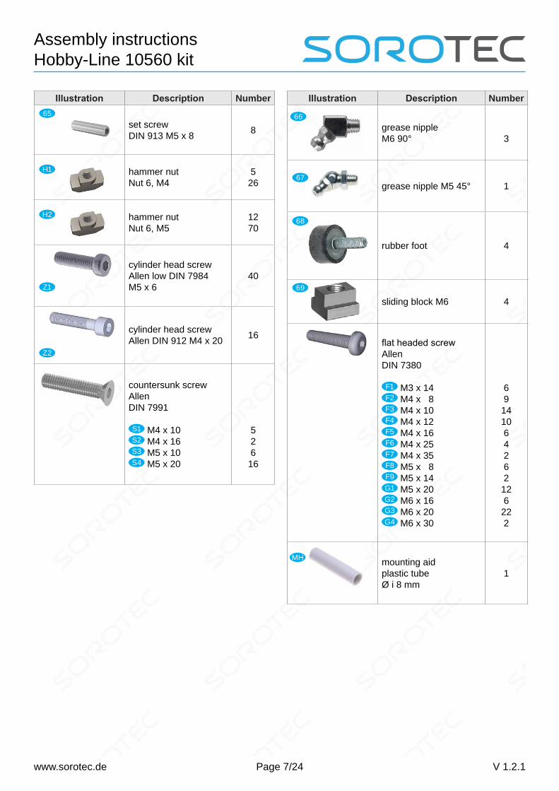
set screwDIN 913 M5 x 8 8
hammer nut Nut 6, M4
5 26
hammer nut Nut 6, M5
12 70
cylinder head screw Allen low DIN 7984 M5 x 6
40
cylinder head screw Allen DIN 912 M4 x 20 16
countersunk screw AllenDIN 7991
S1 M4 x 10S2 M4 x 16S3 M5 x 10S4 M5 x 20
526 16
65
H1
H2
Z1
Z2
Illustration Description Number
grease nippleM6 90° 3
grease nipple M5 45° 1
rubber foot 4
sliding block M6 4
flat headed screwAllen DIN 7380 F1 M3 x 14F2 M4 x 8F3 M4 x 10F4 M4 x 12F5 M4 x 16F6 M4 x 25F7 M4 x 35F8 M5 x 8F9 M5 x 14G1 M5 x 20G2 M6 x 16G3 M6 x 20G4 M6 x 30
69
141064262
126
222
mounting aidplastic tube Ø i 8 mm
1
66
67
68
69
MH
Page 8/24
Assembly instructions Hobby-Line 10560 kit
www.sorotec.de V 1.2.1
Pre-assembly
Portal plates
For this construction phase you need: #
1 right portal plate 20
1 left portal plate 21
1 sleeve bearing 46
8 castor 50
4 centric roller guide 48
4 eccentric roller guide 49
8 self-locking nut M8 63
4 flat nut M8 x 0,75 Fine thread!
51
24 adjusting washer 8 x 14 x 1 mm 52 Fig. 1: Assembly of guide rollers for the portal plate
Fig. 2: Mount the hexagon side of the eccentrics towards the outside of the portal cheek.
48
20
50
6352
52
49
52
51
4848
2021
49 49
• Press the sleeve bearing 46 into the hole on the right portal cheek (see Fig. 17 on page 15).
Assemble the roller guides of the portal cheeks as shown in pictures 1 and 2. Pay attention to the cor-rect installation position of the guide bolts.
• Install the centric roller guides 48 with the hexagon head on the inside into the lower holes of the portal plates 20 21 . Tighten the screw connections well.
• Install the eccentric roller guides 49 with the hexagon socket on the outside in the upper holes of the portal plates. Tighten the screw connections well on the roller side, but only loosely hand-tight on the opposite side - later the guidance of the Y-axis is set here.
Page 9/24
Assembly instructions Hobby-Line 10560 kit
www.sorotec.de V 1.2.1
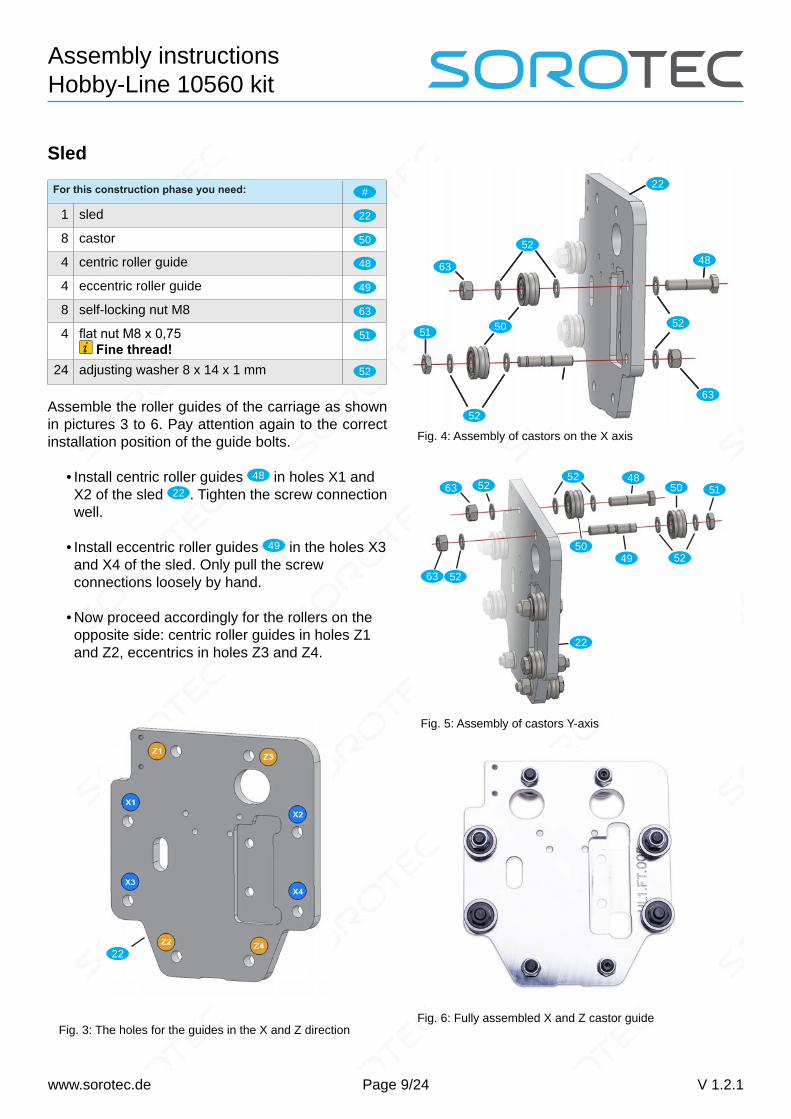
Fig. 4: Assembly of castors on the X axis
Fig. 5: Assembly of castors Y-axis
Fig. 6: Fully assembled X and Z castor guide
52
22
52
51 50 52
60
4860
22
52
51 50 52
63
4863
5152
50
485063
49 52
22
63 52
52
Sled
For this construction phase you need: #
1 sled 22
8 castor 50
4 centric roller guide 48
4 eccentric roller guide 49
8 self-locking nut M8 63
4 flat nut M8 x 0,75 Fine thread!
51
24 adjusting washer 8 x 14 x 1 mm 52
Assemble the roller guides of the carriage as shown in pictures 3 to 6. Pay attention again to the correct installation position of the guide bolts.
• Install centric roller guides 48 in holes X1 and X2 of the sled 22 . Tighten the screw connection well.
• Install eccentric roller guides 49 in the holes X3 and X4 of the sled. Only pull the screw connections loosely by hand.
• Now proceed accordingly for the rollers on the opposite side: centric roller guides in holes Z1 and Z2, eccentrics in holes Z3 and Z4.
Fig. 3: The holes for the guides in the X and Z direction
22
Page 10/24
Assembly instructions Hobby-Line 10560 kit
www.sorotec.de V 1.2.1
Sides of the table
For this construction phase you need: #
2 guide profile 1218 mm 12
4 precision shaft 1257 mm 13
2 table profile 1217 mm 53
16 cylinder head screw M4 x 20 Z2
16 hammer nut M4 H1
sealing profile 10
Fig. 7: Lateral guide profile with attachments
12
13
5310
Prepare the table sides:
• Load the cross holes of the table profiles 53 with cylinder screws Z2 and screw on one hammer nut H1 a turn or two.
• Place the table profiles 12 with the hammer nuts in the upper side groove of the guide profiles (see figure 7). Align to center: Protrusion must be avoided!
• Press the table profile downwards and tighten the screw connection.
• Guide the sealing profile 10 into the designated groove of the guide profile (see picture 7) and cut it flush with a sharp knife.
• Push the precision shafts 13 , on which the castors will run later, into the corresponding channels of the guide profiles. Temporarily secure the shafts with a little tape to prevent them from slipping out.
SpindlesY-axisFor this construction phase you need: #
2 ball screw 16 x 10 mm, L 1258 mm 11
2 fixed bearing retaining plate 4 mm 39
2 fixed bearing spacer plate 2 mm 40
2 fixed bearing seat 41
2 fixed bearing spacer sleeve 42
4 ball bearing 8 x 16 x 5 mm 44
2 adjusting washer 10 x 16 x 1,2 mm 47
2 self-locking nut M8 x 1, Fine thread!
62
2 grease nipple M6 45° 66
2 nut block 23
8 flat headed screw M5 x 20 G1
1 mounting aid MH
4 flat headed screw M6 x 16 G2
pre-assembled portal plates
Attention!Never turn the spindle nut from a ball screw! The spindle nut cannot be reassembled with common tools. A ball screw without a spindle nut has been destroyed and must be replaced with a new part.
Fig. 8: Mounting the fixed bearings on the Y spindles
39
42
62
40
47
41
44
23
11
66
Page 11/24
Assembly instructions Hobby-Line 10560 kit
www.sorotec.de V 1.2.1
Prepare the Y axis spindles:
• First, screw a grease nipple 66 onto each spindle nut.
• Lubricate the spindle nuts with a grease gun and remove excess grease with a rag.
• Mount the nut blocks 23 on the spindle nuts with four flat headed screws G1 each.
• Carefully clamp the spindle between two wooden blocks or plastic jaws in a vice.
• Now assemble the parts of the fixed bearings in the order shown in Figure 8. Use the assembly aid MH and a plastic hammer to push the ball bearings 44 onto the fit of the spindle. Attention: Only press the ball bearing onto the inner ring!
• To adjust the axial play, tighten the shaft nut 62 until the fixed bearing unit can only be
turned around the ball screw with difficulty. Then carefully loosen the shaft nut a little (approx. 5°) until the ball screw can easily be turned again.
• Finally, screw the spindles with flat headed screws G2 to the nut blocks with the portal plates. Do not tighten the screws.
Note:The threads of grease nipples tear off easily. Turn the nipples back a full turn now and then when screwing them in.
Fig. 9: Grease nipples and nut blocks on the spindles of the Y axis.
Fig. 10: Right portal plate with mounted spindle
Page 12/24
Assembly instructions Hobby-Line 10560 kit
www.sorotec.de V 1.2.1
X-axisFor this construction phase you need: #
1 ball screw 16 x 10 mm, L 759 mm 1
1 grease nipple M6 90° 66
1 nut block 23
4 flat headed screw M5 x 20 G1
2 flat headed screw M6 x 16 G2
pre-assembled sled
Prepare the X axis spindle:
• Screw the grease nipple 66 onto the spindle nut.
• Lubricate the spindle nuts with a grease gun and remove excess grease with a rag.
• Mount the nut block with the flat headed screws G1 .
• Finally screw the spindle to the nut block in the milled pocket of the slide using flat-head screws G2 . Do not tighten the screws.
Fig. 11: Sled with the X-spindle installed
Z-axisFor this construction phase you need: #
1 ball screw 12 x 4 mm, L 210 mm 15
1 grease nipple M5 45° 67
1 nut block 24
6 flat headed screw M4 x 16 F5
pre-assembled sled with X-axis
Prepare the Y axis spindle:
• Screw the grease nipple 67 onto the spindle nut.
• Lubricate the spindle nuts with a grease gun and remove excess grease with a rag.
• Mount the nut block with the flat headed screws F5 .
• Finally screw the spindle with flat-head screws F5 on the nut block on the slide, as shown in
• Press the two sleeve bearings 46 into the face plate 5 .
• Use the flat-head screws G3 to screw the two pre-assembled table sides to the face plate 5 , as shown in Fig. 13. Do not tighten the screws.
• Complete the rubber feet 68 with an M6 nut 60 , a washer 57 and a sliding block 69 . Insert
the feet with the sliding block into the lower longitudinal groove of the side profiles and screw the feet tight as shown in Fig. 14.
Continued on next page.
Page 14/24
Assembly instructions Hobby-Line 10560 kit
www.sorotec.de V 1.2.1
• Remove the adhesive tape with which you secured the guide rails (precision shafts 13 ) in the table sides against slipping out.
• Trace the right portal plate into the guide on the right side of the table, as shown in Fig. 15. To do this, loosen the screw connections of the eccentrics if necessary and turn them with an Allen key until the rollers run tension-free on the rails.
• Insert the front end of the spindle into the sleeve bearing pressed into the face plate.
• Proceed in the same way with the left portal plate.
Fixed bearing side
• Use flat-head screws G3 to mount the rear end
face plate 4
on the table sides. Do not tighten the screws.
• Use flat-head F6 screws to screw the fixed bearings of the Y-spindles to the rear face plate. Do not tighten the screws.
Note:The exact setting of the roller guide will be done later.
Fig.15: Installation of the right portal cheek
Figure 16: Bolted fixed bearing of the right Y-spindle
Page 15/24
Assembly instructions Hobby-Line 10560 kit
www.sorotec.de V 1.2.1
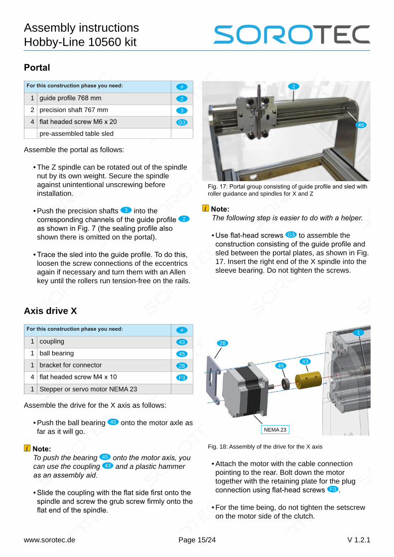
Portal
For this construction phase you need: #
1 guide profile 768 mm 2
2 precision shaft 767 mm 3
4 flat headed screw M6 x 20 G3
pre-assembled table sled
Assemble the portal as follows:
• The Z spindle can be rotated out of the spindle nut by its own weight. Secure the spindle against unintentional unscrewing before installation.
• Push the precision shafts 3 into the corresponding channels of the guide profile 2 as shown in Fig. 7 (the sealing profile also shown there is omitted on the portal).
• Trace the sled into the guide profile. To do this, loosen the screw connections of the eccentrics again if necessary and turn them with an Allen key until the rollers run tension-free on the rails.
Fig. 17: Portal group consisting of guide profile and sled with roller guidance and spindles for X and Z
Note:The following step is easier to do with a helper.
• Use flat-head screws G3 to assemble the construction consisting of the guide profile and sled between the portal plates, as shown in Fig. 17. Insert the right end of the X spindle into the sleeve bearing. Do not tighten the screws.
46
2
Axis drive X
For this construction phase you need: #
1 coupling 43
1 ball bearing 45
1 bracket for connector 28
4 flat headed screw M4 x 10 F3
1 Stepper or servo motor NEMA 23
Assemble the drive for the X axis as follows:
• Push the ball bearing 45 onto the motor axle as far as it will go.
Note:To push the bearing 45 onto the motor axis, you can use the coupling 43 and a plastic hammer as an assembly aid.
• Slide the coupling with the flat side first onto the spindle and screw the grub screw firmly onto the flat end of the spindle.
Fig. 18: Assembly of the drive for the X axis
• Attach the motor with the cable connection pointing to the rear. Bolt down the motor together with the retaining plate for the plug connection using flat-head screws F3 .
• For the time being, do not tighten the setscrew on the motor side of the clutch.
28
1
4345
NEMA 23
Page 16/24
Assembly instructions Hobby-Line 10560 kit
www.sorotec.de V 1.2.1
Tightening the basic screw connec-tion and adjusting the castorsYour portal milling machine has now been set up so far that all screw connections can be tightened and the castors on the X and Y axes can be adjusted. To do this, proceed as follows:
X-axis
• Push the sled all the way to the left by hand (motor side of the spindle).
Note:If the sled is very difficult or impossible to move, check whether two or more of the motor cables are short-circuited. In this case, the motor can also act as a strong brake without external wiring.
• Push the guide profile forwards and downwards while tightening the connecting screws on the portal plates.
• Loosen the nuts of the eccentric roller guides.
• Now set the guide rollers one after the other. To do this, turn the eccentric with an Allen key until the roller lies against the rail. Continue to turn the eccentric until you can feel a clear resistance - but never more than 5 degrees after the roller is in contact.
• Tighten the nut of the set roller guide and repeat the setting for the second roller.
• Tighten the set screw on the motor side of the coupling on the X motor.
• Tighten the screw connection between the sled and the nut block of the X axis.
Y-axis
• Push the portal all the way back by hand (fixed bearing side of the Y-spindles).
• Press the sides of the table inwards and downwards while tightening the connecting screws on the face plates.
• Set the roller guides of the portal plates as described for the rollers on the X axis.
• Tighten the screws of the fixed bearings on the rear face plate.
• Tighten the screw connections between the portal plates and the nut blocks of the Y spindles.
Fig. 19: Adjusting the guide rollers
Page 17/24
Assembly instructions Hobby-Line 10560 kit
www.sorotec.de V 1.2.1
Axis drive Y
For this construction phase you need: #
2 toothed belt wheel 6 mm hole 7
1 toothed belt wheel 6.35 mm hole 8
1 timing belt 9
1 locating screw M6 x 25 36
2 adjusting washer 8 x 14 x 0,2 mm 37
2 flange ball bearing 38
2 washer M8 56
1 washer M6 57
1 self-locking nut M6 61
4 flat headed screw M4 x 10 F3
1 bracket angled for plug connection 29
2 flat headed screw M4 x 8 F2
1 Stepper or servo motor NEMA 23
Assemble the drive for the Y axis as follows:
Fig. 20: Y motor and holding plate for plug connection
Fig. 21: Mounting the tension pulley (surrounding compo-nents are not shown for clarity)
Fig. 22: Structure of the timing belt drive
F3 F2
NEMA 23
29
3736
57
38
61
56
7 7
8
9
• Use flat-head screws F3 to bolt the motor into the hole provided in the rear end plate.
• Fasten the holding plate for the plug connection 29 with flat-head screws F2 , as shown in Fig. 20.
• Assemble the tension pulley as shown in Fig. 21. Do not tighten the screw connection yet.
• Place the toothed belt wheels 7 with the clamping side facing outwards on the Y spindles and tighten the clamping screws.
• Place the toothed belt wheel 8 on the motor shaft with the clamping side facing inwards and tighten the clamping.
• Put on the timing belt 9 as shown in Fig. 22.
• Tighten the timing belt with the tension pulley and tighten the screw connection of the pulley.
Note:The belt tension is set correctly if:
• on the one hand there is no sag visible and• on the other hand the free rotation is not hindered.
Page 18/24
Assembly instructions Hobby-Line 10560 kit
www.sorotec.de V 1.2.1
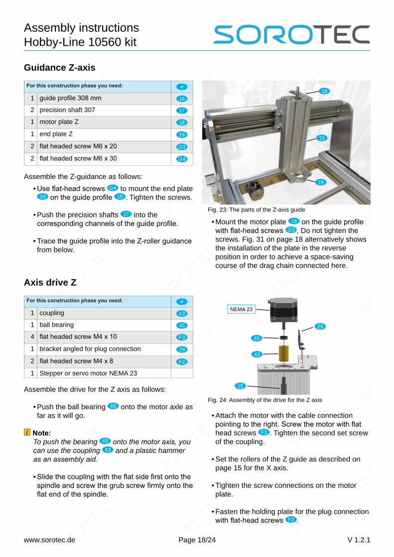
Guidance Z-axis
For this construction phase you need: #
1 guide profile 308 mm 16
2 precision shaft 307 17
1 motor plate Z 18
1 end plate Z 19
2 flat headed screw M6 x 20 G3
2 flat headed screw M6 x 30 G4
Assemble the Z-guidance as follows:
Fig. 23: The parts of the Z-axis guide
16
18
19• Use flat-head screws G4 to mount the end plate
19 on the guide profile 16 . Tighten the screws.
• Push the precision shafts 17 into the corresponding channels of the guide profile.
• Trace the guide profile into the Z-roller guidance from below.
• Mount the motor plate 18 on the guide profile with flat-head screws G3 . Do not tighten the screws. Fig. 31 on page 18 alternatively shows the installation of the plate in the reverse position in order to achieve a space-saving course of the drag chain connected here.
Axis drive Z
For this construction phase you need: #
1 coupling 43
1 ball bearing 45
4 flat headed screw M4 x 10 F3
1 bracket angled for plug connection 29
2 flat headed screw M4 x 8 F2
1 Stepper or servo motor NEMA 23
Assemble the drive for the Z axis as follows:
• Push the ball bearing 45 onto the motor axle as far as it will go.
Note:To push the bearing 45 onto the motor axis, you can use the coupling 43 and a plastic hammer as an assembly aid.
• Slide the coupling with the flat side first onto the spindle and screw the grub screw firmly onto the flat end of the spindle.
Fig. 24: Assembly of the drive for the Z axis
• Attach the motor with the cable connection pointing to the right. Screw the motor with flat head screws F3 . Tighten the second set screw of the coupling.
• Set the rollers of the Z guide as described on page 15 for the X axis.
• Tighten the screw connections on the motor plate.
• Fasten the holding plate for the plug connection with flat-head screws F2 .
NEMA 23
45
43
15
29
Page 19/24
Assembly instructions Hobby-Line 10560 kit
www.sorotec.de V 1.2.1
Rail Locking
For this construction phase you need: #
8 set screw 65
The precision shafts that serve as rails for the roller guides must be secured against slipping. To do this, screw the set screws 65 into the corresponding ho-les:
• left and right in the rear face plate• in the left portal plate (engine side)• in the motor plate of the Z guide
Note:Tighten the grub screws carefully hand-tight! Excessive preload on the rails leads to crackling noises when moving the axes.
Fig. 25: Threaded holes for the rail lock
65
6565
65
65
65 65
65
Side covers
For this construction phase you need: #
2 cover profile 14
1 sealing profile 10
8 flat headed screw M6 x 20 G3
Assemble the side covers as follows:
• Guide the sealing profile 10 into the designated groove of the cover profile and cut it flush with a sharp knife.
• Mount the cover profiles with flat headed screws G3 . The cover profiles are deliberately one millimeter shorter than the table profiles for better mobility. Do not overtighten the screws to avoid bending the face plates.
Fig. 26: For maintenance of the spindles, the side covers can be easily opened after removing the upper screws.
Attachment parts
Emergency switch
For this construction phase you need: #
1 Emergency switch 30 mm 55
• Mount the emergency stop switch in the hole provided in the front face plate, as shown in Fig. 27.
Fig. 27: Emergency stop switch, view from behind
Page 20/24
Assembly instructions Hobby-Line 10560 kit
www.sorotec.de V 1.2.1
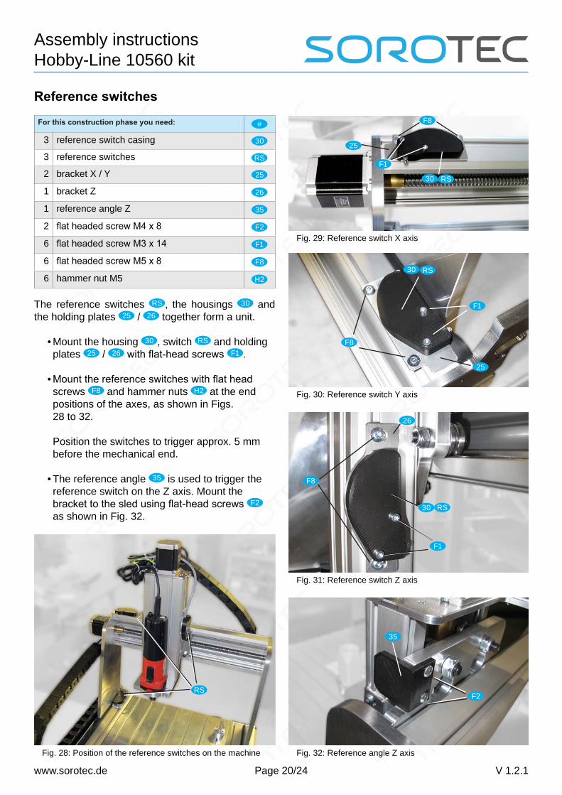
Reference switches
For this construction phase you need: #
3 reference switch casing 30
3 reference switches RS
2 bracket X / Y 25
1 bracket Z 26
1 reference angle Z 35
2 flat headed screw M4 x 8 F2
6 flat headed screw M3 x 14 F1
6 flat headed screw M5 x 8 F8
6 hammer nut M5 H2
The reference switches RS , the housings 30 and the holding plates 25 / 26 together form a unit.
• Mount the housing 30 , switch RS and holding plates 25 / 26 with flat-head screws F1 .
• Mount the reference switches with flat head screws F8 and hammer nuts H2 at the end positions of the axes, as shown in Figs. 28 to 32. Position the switches to trigger approx. 5 mm before the mechanical end.
• The reference angle 35 is used to trigger the reference switch on the Z axis. Mount the bracket to the sled using flat-head screws F2 as shown in Fig. 32.
Fig. 28: Position of the reference switches on the machine
RS
Fig. 29: Reference switch X axis
Fig. 30: Reference switch Y axis
Fig. 31: Reference switch Z axis
Fig. 32: Reference angle Z axis
F1
30 RS
25
F8
RS30
25
F1
F8
26
30 RS
F1
F8
35
F2
Page 21/24
Assembly instructions Hobby-Line 10560 kit
www.sorotec.de V 1.2.1
Drag chains
For this construction phase you need: #
1 drag chain angle 27
2 drag chain 31
2 connector kit for drag chain 32
1 mounting bracket for drag chain 33
5 flat headed screw M4 x 8 F2
5 hammer nut M4 H1
2 flat headed screw M5 x 14 F9
5 countersunk screw M4 x 10 S1
2 countersunk screw M4 x 16 S2
3 washer M4 58
3 nut M4 59
6 cable tie block 34
6 countersunk screw M5 x 10 S3
6 hammer nut M5 H2
Proceed as follows to assemble:
Fig. 33: Mounting the drag chain angle 27 on the back of the guide profile for the X axis
Fig. 34: Assembly of the drag chain for the X axis. Deviating from the standard construction, the motor plate 18 with the drag chain support is installed on the inside to save width.
Fig. 35: Assembly of the drag chain for the Y axis
27
31
F2
S1
12
31 27
F2
32
18
F9
S1
33
32
31S2
58 59
• Attach the drag chain angle 27 to the back of the guide profile 12 using flat-head screws F2 and hammer nuts H1 , as shown in Figs. 32 and 34.
• Fasten the connection kit 32 to the motor plate 18 using countersunk screws S1 . Adjust the
length of the X drag chain 31 by removing or adding links.
• Hang the X drag chain in the connection kit and fasten the free end to the drag chain bracket with countersunk screws S1 , washers 58 , nuts 59 and the second part of the connection kit,
as shown in Fig. 33.
• Mount the mounting bracket 33 with flat-head screws F9 on the right portal plate, as shown in Fig. 35.
• Screw the second connection kit 32 to the mounting bracket with two countersunk screws S2 , washers 58 und nuts 59 and adjust the
length of the Y drag chain 31 .
• Hang the Y-drag chain in the connection kit and fasten the free end to the rear face plate using the connection kit and countersunk screws, as shown in Fig. 35.
The cable tie blocks 34 can be fixed in the profile grooves with countersunk screws S3 and hammer nuts H2 and serve as variable fastening points for the cabling.
Page 22/24
Assembly instructions Hobby-Line 10560 kit
www.sorotec.de V 1.2.1
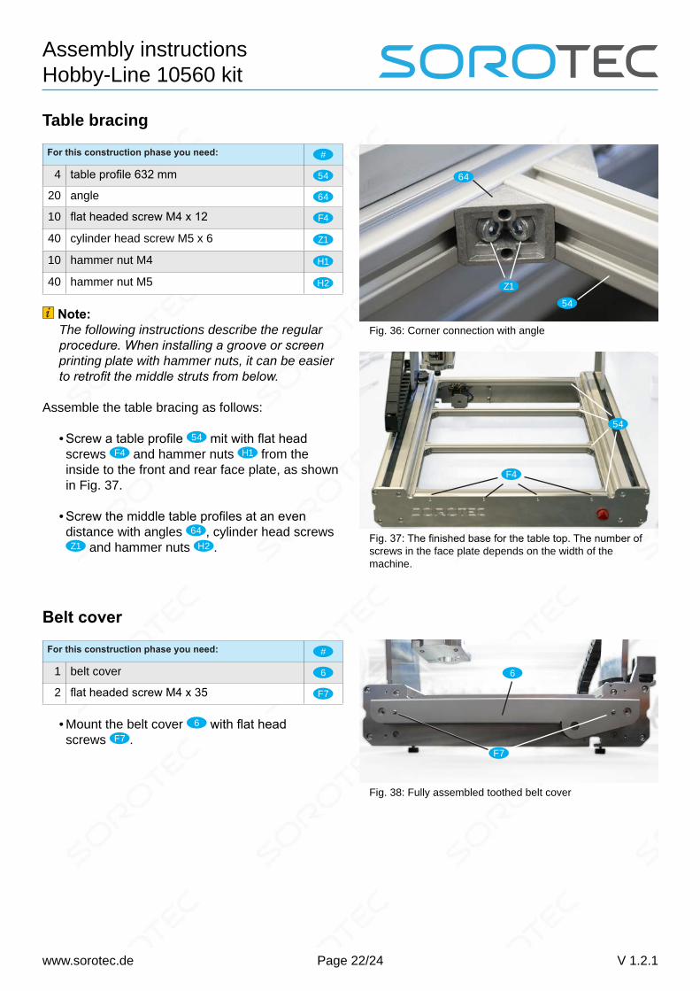
Table bracing
For this construction phase you need: #
4 table profile 632 mm 54
20 angle 64
10 flat headed screw M4 x 12 F4
40 cylinder head screw M5 x 6 Z1
10 hammer nut M4 H1
40 hammer nut M5 H2
Note:The following instructions describe the regular procedure. When installing a groove or screen printing plate with hammer nuts, it can be easier to retrofit the middle struts from below.
Assemble the table bracing as follows:
• Screw a table profile 54 mit with flat head screws F4 and hammer nuts H1 from the inside to the front and rear face plate, as shown in Fig. 37.
• Screw the middle table profiles at an even distance with angles 64 , cylinder head screws Z1 and hammer nuts H2 .
Fig. 36: Corner connection with angle
Fig. 37: The finished base for the table top. The number of screws in the face plate depends on the width of the machine.
64
Z1
54
54
F4
Belt cover
For this construction phase you need: #
1 belt cover 6
2 flat headed screw M4 x 35 F7
• Mount the belt cover 6 with flat head screws F7 .
Fig. 38: Fully assembled toothed belt cover
6
F7
Page 23/24
Assembly instructions Hobby-Line 10560 kit
www.sorotec.de V 1.2.1
MaintenanceIn normal use, the portal milling machine should be lubricated every six months, but at the latest after twelve months. To do this, proceed as follows:
All axes• When removing excess grease, wipe with a cloth over the precision shafts of the roller guide to counteract the formation of flash rust.
X axis• Remove the Z-axis reference angle 35 .• Remove the end plate 19 of the Z axis with the milling spindle mounted in it.
• Loosen the spindle-side clamping screw in the drive coupling 43 of the Z axis.
• Lift the Z-axis guide profile 16 upwards out of the roller guide.
• Lubricate the spindle nut of the X axis with a grease gun, as shown in Fig. 39.
• Remove excess fat with a rag.• Assemble the Z-axis parts back into place.
Fig. 39: Lubricating the X axis
Note:There is a video instruction about lubrication: https:// youtu.be/mlZTcE045v0
Note:As a grease gun, we recommend the „mini grea-se gun“ set from the Sorotec online shop (item no. SM.00018).
Common multi-purpose grease is sufficient to lubricate the spindle nuts.
The guide rollers are encapsulated and lubri-cated for life. Lubrication is neither possible nor necessary.
Page 24/24
Assembly instructions Hobby-Line 10560 kit
www.sorotec.de V 1.2.1
Y axis• Remove the top screws of the cover profiles 14 at the front and rear.
• Loosen the lower screws and open the covers.• Lubricate the Y axis spindle nuts as shown in Figs. 39 and 40.
• Close and screw on the covers.
Z axis• Lubricate the Z-axis spindle nut as shown in Fig. 41.