14
ASSEMBLY INSTRUCTIONS D-DOME SYSTEM USA

ASSEMBLY INSTRUCTIONSD-Dome SyStem
USA

2
3
4
5
7
9
14
TABLE OF CONTENTS
THE COMPANY
SAFETY REGULATIONS
MATERIALS REQUIRED
TOOLS REQUIRED
ASSEMBLY
TERMS AND CONDITIONS
Table of conTenTs
2 | 14 Table of contents

engineering sTrengTh is aT our core
With sophisticated product innovations and a deep customer focus, Everest Solar is the engineering leader for all your mounting system needs. We are the US division of K2 Systems, one of Europe’s market leaders with more than 2.5 GW installed.
We offer proven product solutions and innovative designs. Wind tunnel testing along with advanced struc-tural and electrical validation that should facilitate permitting, design and installation. Our designs result in cost competitive racking systems with dedicated support that will position you to win more projects.
We partner with our customers and suppliers for the long-term. High quality materials and cutting edge designs provide a durable, yet functional system. Our product line is comprised of a few, coordinated com-ponents that lower the cost of materials, and simplify installation, saving you time and money. All backed by German engineering, a long track record of quality, and a company that is here to stay.
Thank you for choosing Everest Solar mountings systems for your Solar PV Project.
3 | 14The Company

general safeTY insTrucTions
Everest Solar Systems’ General Assembly Instructions must be followed to maintain the exclusive, limited pro-duct warranty.You can access these instructions at Everest Technical Info Page http://www.everest-solarsystems.com/us/downloads/technical-information.html or by contacting us directly.
In general, the following applies:
¬ Systems should be installed by experienced contractors licensed and qualified to perform the work with pro-fessional workmanship and quality.
¬ Before installation, Contractor must verify that the system meets all applicable laws, regulations, ordinances, and codes. Contractor shall verify that the roof or other structures to which the system is being attached are capable of carrying the system loads. For information about the dead loads of the various system compo-nents, Contractor should review the Everest Technical information page at http://www.everest-solarsystems.com/us/downloads/technical-information.html or contact us directly
¬ Contractor is solely responsible for work safety and accident prevention regulations and corresponding stan-dards and regulations of the applicable occupational safety and health agency are followed, including:
- Safety clothing is worn such as safety helmets, work shoes, and gloves. - Where required, the contractor should use fall protection, scaffolding with arrestor equipment and other
approved methods for worker safety
¬ Contractor shall verify that it is using the most current instructions by downloading the latest version from our website or contacting our office directly.
¬ Module manufacturer installation guides must be followed. Please use approved electrical bonding and grounding components that are required by the local or national codes and AHJ.
¬ A copy of these instructions must be on site, and read and understood by all workers during installation
¬ In the event our general installation and assembly instructions are not followed, or that not all system compo-nents and assemblies are used according to these instructions, or that components are used which were not obtained from us, Everest Solar Systems is not liable for any resulting defects and damages, and the exclusive, limited warranty will be void.
¬ The exclusive, limited product warranty shall apply only if all instructions are strictly adhered to and the sys-tem is correctly installed. Everest Solar Systems disclaims any and all warranties, express or implied, including without limitation any warranties of merchantability and fitness for a particular purpose other than as set forth in the exclusive, limited warranty in the terms and conditions of sale, which can be viewed under on our website: http://www.everest-solarsystems.com/us/downloads/technical-information.html
¬ The dismantling of the system should be in reverse order of these assembly instructions.
4 | 14Safety Regulations

essenTial: The MaTerials reQuireD
| 1006200
| 1006199
| 2000084
| 1006039
Building protection mat 0.24 inch (6 mm)
Material: PUR bound rubber granules with aluminium triplex foil, laminated
Alternative: Building protection mat 0.24 inch (6 mm)Material: PUR bound rubber granules unlaminated
Alternative: Building protection mat 0.79 inch (20 mm) Dimensions: 47.24 x 3.94 inch (1200x100 mm)
The particular use of a laminated or non-laminated building protection mat depends on the material of the roofing and must therefore be checked on site.
FlatConnector Set XPressRail / FlatRail
Material: Aluminum
| 1005840
| 1005839
Dome D1000
Material: Aluminum, Width: 3.54 inch (90 mm)
Alternative: Dome D800, Width: 3.54 inch (90 mm)
M K2 slot nut with clip
Material: stainless steel, plastic
Allen Bolt DIN 912 EN ISO 4762 M8
Material: stainless steel
Lock washer DIN EN 10151
Material: stainless steel
| 1001643
| item number system-specific
| 1000473
| 1005842Dome SD
Width: 3.54 inch (90 mm) Material: Aluminum
XPressRail 22 (20 ft / 2.10 m)
Material: Aluminum
| 1001163
Below is a reference for the parts required to assemble the Everest D-Dome system. Exact quantities are based on your project requirements.
5 | 14Materials Required
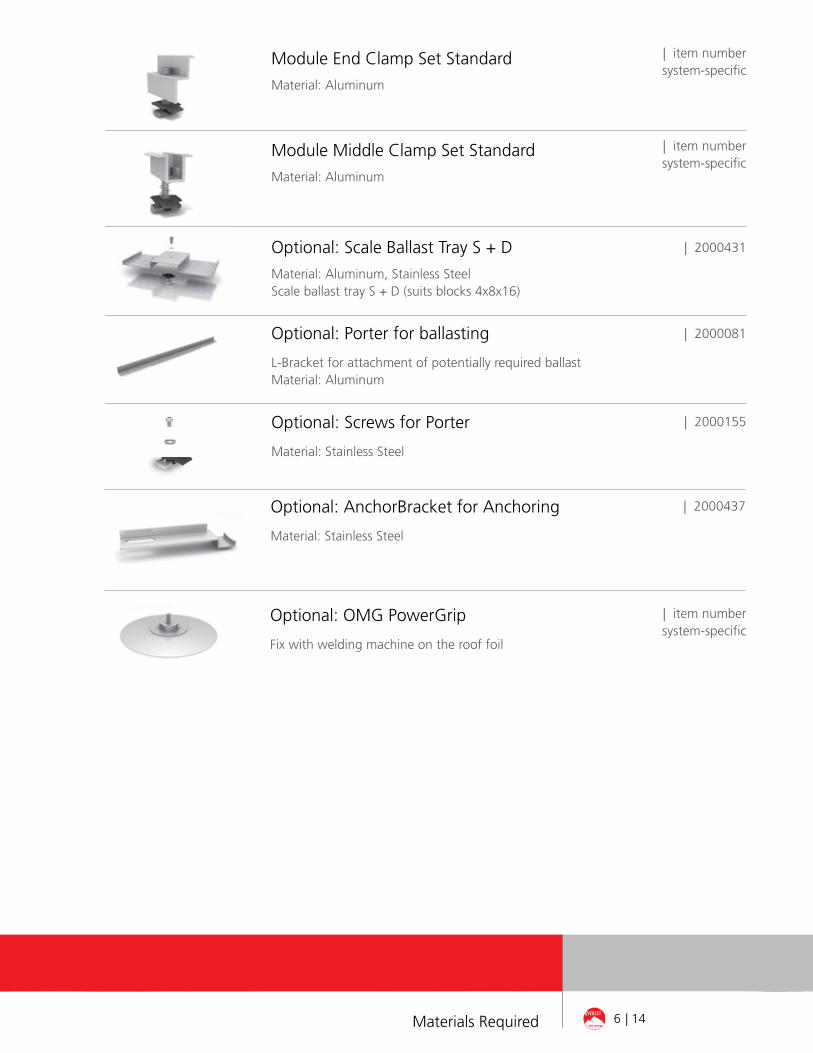
Module End Clamp Set Standard
Material: Aluminum
Module Middle Clamp Set Standard
Material: Aluminum
| 2000431Optional: Scale Ballast Tray S + D
Material: Aluminum, Stainless SteelScale ballast tray S + D (suits blocks 4x8x16)
| item number system-specific
| item number system-specific
| 2000081
| 2000155
Optional: Porter for ballasting
L-Bracket for attachment of potentially required ballastMaterial: Aluminum
Optional: Screws for Porter
Material: Stainless Steel
| 2000437Optional: AnchorBracket for Anchoring
Material: Stainless Steel
Optional: OMG PowerGrip
Fix with welding machine on the roof foil
| item number system-specific
6 | 14Materials Required

aT a glance: oVerVieW of The Tools
Measuring tape
Torque wrench
With attachment for HW 6
Chalk line
Everest Solar Systems are designed to make installation easy and fast. The basic tools required to assemble the parts are listed below as a guide.
Tools and materials for the installation of third party items such as roof attachment products, roof covering and sealing products or items used for bonding and grounding are not listed here. Please refer to the instructions of those third party products.
bonDing anD grounDing:
Appropriate means of bonding and grounding are required by regulation. Everest Solar Systems meets these requirements on the D-Dome system by incorporating the Everest Solar MK2 Slot Nut and the successfully tested Burndy WEEB KMC and WEEB Lug 6.7.
The Burndy WEEB KMC bonds the module to the D-Dome as displayed as “Y” on page 4 of the Burndy Manual for D-Dome. All other Everest Solar Components in the D-Dome system are bonded together using the MK2 Slot Nut including the D-Dome, SD-Dome, and the Flat Connector to splice the XPressRail. The MK2 is ETL listed to UL 467. As an alternative to the MK2, the WEEB KMC can be used to bond the Dome to the Rail as seen on page 3-4 of the Burndy Manual for D-Dome. The grounding of the rail is achieved using the Burndy WEEB Lug 6.7.
Please refer to the Burndy Installation Manual to review how the WEEB KMC and WEEB Lug 6.7 are to be used in conjunction with the Everest Solar D-Dome system. The installation instructions of all Everest Solar bonding components can be found in the Everest Solar D-Dome Installation Manual. The Burndy and Everest Solar Instal-lation Manuals are available on our website: http://www.everest-solarsystems.com/us/downloads/technical-information.html
7 | 14Tools Required

8 | 14Installation of D-Dome System
in general:
¬ The General Installation Instructions must be adhered to. These can be found at our download area at: http://www.everest-solarsystems.com/us/downloads/technical-information.html
¬ Should you not have login details for our customer area, please contact us and we will send them to you.
¬ This system can be installed for all standard flat roofs with pressure-resistant substrates and a roof pitch of up to 5 degrees. The elevation angle is 10°.
¬ It is recommended to place a separation layer between the roofing and the rail prior to laying the XPressRail in order to protect the roofing. The rail is positioned directly on the separation layer without roof penetrati-on. The compatibility of the building protection mat with the particular roofing must be checked on-site.
¬ Minimum distance to roof edge: 19.69 inch (500 mm).
¬ At least 3 rows of three double elevation systems (a total of 18 modules) must be installed consecutively in order to use this system.
¬ The D-Dome D1000 or D800 System is suitable for modules with a frame height of 1.18 - 1.97 inch (30 - 50 mm). This system is not suitable for thin-film modules.
¬ Modules with a length of 62.2 - 66.14 inch (1,58 to 1,68 m) can be used. For module widths of 37,4 - 41,34 inch (950 - 1050 mm), the Dome D1000 is fitted, for module widths between 29,13 - 33,1 inch (740 - 840 mm), the Dome D800.
¬ After 52.5ft (16.0 m) and up to 60ft (18.3 m) rail length it is necessary to provide for a thermal separation of max. 6inch (15 cm) in both directions: north-south and east-west.
¬ For the installation of the D-Dome D1000 or D800 Systems, only standard clamps may be fitted. The AddOn may not be used.
¬ It is essential to clarify, from the start, whether there is a module manufacturer‘s approval available for the clamping on the short side of the D-Level Dome D1000 or D800 installation systems. You can obtain the approval list from your customer consultant or at http://www.everest-solarsystems.com/us/downloads.html.
¬ Because of the different orientation of the solar modules, the string and inverter connection must be appropriately observed. It is recommended that the inverters and strings are connected separately.
¬ If required, paving blocks can be inserted in the base plate of the Scale S- and D-Dome for ballasting on the XPressRail. For higher ballast we recommend using the Porter.

PoSition XPreSSrail
inStall rail connectorS
These assembly instructions only apply to flat roofs with a maximum roof pitch of 5°.It is recommended to place a separation layer between the roofing and the rail prior to laying the flat rail in the form of a building protection mat in order to protect the roofing.The building protection mat is installed with the alumi-num concealed side facing downwards. The XPressRail is positioned directly on the separation layer without roof penetration.The parallel distance between the individual XPressRails is defined by the dimensions of the modules. For a standard clamp, the recommended distance between two rails corres-ponds to the module length plus 0.787 inch (20 mm).
the building protection mats must be laid at the joint with a separation of approx. 0.39 inch (10 cm), in order to allow any accumulated water to flow off.
Materials required: XPressRail, building protection mat
Two XPressRails are connected at the rail joint using a rail connector. This locks the XPressRails in the longitudinal direction. Insert two M K2 slot nuts in the rail and turn 90° clockwise to lock. Fasten rail connectors with two M8 Allen bolts and one locking washer each. The connector should be between the Dome D1000 and Dome SD.
If the rail lengths permit, the rail joint can also be positioned directly below the Dome D1000 without a rail connector. However, it must be ensured that the joint is between the two fittings and under no circumstances directly at the screw position.
Note: When joining the Rails with either the rail connector or D-Dome, the rails and connecting component are bon-ded as the MK2 has been listed as a UL467 bonding device in these configurations.
Torque: 10.3 lbf-ft (14 Nm)
Materials required: FlatConnector Set
1of 8
2of 8
9 | 14Installation of D-Dome System
insTallaTion of D-DoMe sYsTeM: sTeP bY sTeP

10 | 14Installation of D-Dome System
Insert two MK 2 slot nuts in the rail and turn 90° clockwise until they lock. Thereafter, position the Dome D1000 on the rail and fasten with two M8 x 20 Allen bolts and S8 locking washers. Torque: 11.8 lbf-ft (16 Nm)
Materials required: Dome D1000, M K2, Allen bolt DIN 912 M8 x 20, S8 locking washer
Fit Dome D1000 3of 8
Fit Dome SD
Insert one M K2 in the rail on each side of the Dome D1000 and turn 90° clockwise until they lock. Then, position two Dome SDs on to the rail and secure tightly with an M8 x 20 Allen bolt and S8 locking washer.Align both Dome SDs as per the adjacent figure.The distance between Dome SD and Dome D1000 is approximately equal to the module width.
Materials required: Dome SD, M K2, Allen boltDIN 912 M8 x 20, S8 locking washerTorque: 11.8 lbf-ft (16 Nm)
4of 8
BallaSt the SyStem
oPtional: Scale
For some roof areas the system might need to be additionally ballasted against any wind suction that may occur.To do this, simply insert the Scale on to the XpressRail via the M K2, screws and locking washer. The Scale should be positi-oned betwen the D-Dome and the SD-Dome.
The Scale can fit on each side conrete blocks of 4 x 8 x 16 inch.
The substrate in the area of the Scale should be protected with additional building protection mats.Torque: 10.3 lbf-ft (14 Nm)
5a of 8

oPtional: Porter
For higher ballast we recommend using the Porter. The L-Brackets are fastened to the rails with the enclosed screws, locking washers and M K2. Torque 11,8 lbf-ft (16 Nm). The spacing of the L-Brackets depends on the size of the ballast stones.
The Porters can be positioned both centrally to the Dome 800/1000, or laterally to the middle Dome.Each Porter set can be ballasted with up to 308,6 lb (140kg).
Materials required: K2 Porter, M K2, Allen boltDIN 912 M8 x 20
5bof 8
PoSition moDuleS anD Dome SDScrew inThe modules are laid horizontally, in the centre of two Dome D1000s. The specially affixed bars serve as the stop. Thereafter, the module is positioned on two Dome SDs. The lightly secured Dome SDs are pushed to the stop in direction of the module and screwed in.Torque: 11.8 lbf-ft (16 Nm).
attention:only modules approved for clamping may be used on the short side, see point „General ruleS“ on page 8 and the note on page 12. Please take care not to cover any drainage holes in modules, as otherwise potential condensation cannot run off.
Materials required: Module
6of 8
oPtional: anchorinG
With the AnchorBracket the D-Dome System can be fixed onto third party brackets, e.g. OMG Power Grip.The AnchorBracket is geometrically connected into the chan-nel of the XpressRail and screwed onto the thread bolt from the OMG with an nut.The position and the quantity of AnchorBrackets and fixations has to be calculated with our Software Everest Base.
5c of 8
11 | 14Installation of D-Dome System

12 | 14Installation of D-Dome System
overall SyStem, corner clamPinG
Due to the double-sided orientation of the modules and the elevation angle of 10°, the rows can generally be installed next to each other without shading clearance. However, we recommend that for potential maintenance work a foot-wide gap is left between the modules.
8of 8
7of 8
First, insert the M K2 slot nut into the nut of the Dome SD and the Dome D1000 and turn 90° clockwise.
Screw the modules at the end of each row with end clamps, DIN 912 M8 screws and S8 locking washers into the slot nuts. If the end and mid clamp set is supplied, fasten the entire set in the groove.
Use two standard middle clamps each between two modu-les which are also fastened with DIN 912 M8 screws and S8 locking washers in the slot nuts.
Alternatively, XS mid clamps can be used.However, longer screws must be used in this case.
Torque: 10.3 lbf-ft (14 Nm).
Materials required: End / mid clamp, M K2, DIN 912 M8 Allen bolt, S8 locking washer
FaSten moDule

TerMs anD conDiTions
Product images are for illustrative purposes only. Specifications are subject to change without notice. All sales of our products shall be subject to Everest Solar Systems terms and conditions, including the exclusive limited warranty set forth therein. The terms and conditions can be found at http://www.everest-solarsystems.com/us/downloads/technical-information.html
PoSition XPreSSrail
For module widths between 29,13 - 33,1 inch (780 - 840 mm), the Dome D1000 is replaced by the Dome D800. The installation itself is the same, only the distance between the Domes is different.
1bof 1
alTernaTiVe sYsTeM VarianT: DoMe D800
ThanK You for choosing a eVeresT MounTing sYsTeM.
Systems from K2 Systems are fast and simple to install. We hope these instructions have helped you in this. Please contact us if you have any questions or suggestions for improvements. We are looking forward to receive your call on our
Service-hotline +1.760.301.5300
ready!
13 | 14Terms and Conditions

Montageanleitung D-Dome - crossrail | us1 | 1112Product images are for illustrative purposes only. Specifications aresubject to change without notice. All sales of our products shall besubject to Everest Solar Systems terms and conditions, includingthe exclusive limited warranty set forth therein.
K2 Systems International: World headquarters K2 Systems GmbH, Germany
K2 Systems SARL, FranceK2 Systems SRL, ItalyK2 Solar Mounting Solutions Ltd., UK
Everest Solar Systems, LLC 3809 Ocean Ranch Blvd.Suite 111Oceanside, CA 92056Tel. +1.760.301.5300info@everest-solarsystems.comwww.everest-solarsystems.com


