28
www.maco.eu Only for use by certified specialists! Not for end users! MULTI SKY Hardware for skylights Timber and PVC ASSEMBLY INSTRUCTIONS TILT AND TURN HARDWARE TECHNOLOGY IN MOTION

www.maco.eu
Onlyfor use by certified specialists!
Not for end users!
MULTI SKYHardware for skylights Timber and PVC
ASSEMBLY INSTRUCTIONS
TILT AND TURN HARDWARE
TECHNOLOGY IN MOTION

Key
Sash rebate height
Sash rebate width
Maximum sash weight
Sash rebate width and height
Abbreviations
SRW = sash rebate width
SRH = sash rebate height
FL = air gap
Ü = rebate leg
V = offset
FT = rebate depth
Notes: Ifnototherwisespecified,thedimensionsarestatedinmillimetresandpackingunitsinitemsper box.
All illustrations are purely symbolic.
Further technical documents can be found in our online catalogue (TOM) at extranet.maco.eu
This print document is continuously revised and the current version can be downloaded from www.maco.eu.
Ifyouhaveanyideasorsuggestionsforimprovingourinstructions,pleasesendthemby e-mailto:[email protected]
MM = MULTI-MATIC
MM-KS = MULTI-MATICwithtiltlockbolt
TO = Pot (hinge-side)
DT = dual-drill holes
AS = surface mounted (hinge-side)
General processing information
Intended purpose 4 Instructions for use 4 - 10
Contentofthebasicpack 11
Hardware combinations
Hardwarecombination,completeunit 12 Hardwarecombination,skylightsash 13
Installing the hardware components on the frame
Routing pattern 14 Drilling-hole pattern 16 Initiallubrication,kinematics 17 Installingkinematiccomponents 18 - 20
Installing the hardware components on the sash
Central sash 21 Skylightsash 22
Hinging the sash in the frame 23
Tearingthroughthecentrallockingsystem 24
Skylightsettings 25 - 26
Contents
Assembly instructions for timber or PVC central locking system and the hinge-side used (PVC, AS, DT) are also binding and must be followed.
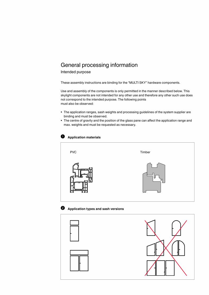
These assembly instructions are binding for the “MULTI SKY” hardware components.
Use and assembly of the components is only permitted in the manner described below. This skylightcomponentsarenotintendedforanyotheruseandthereforeanyothersuchusedoesnot correspond to the intended purpose. The following points must also be observed:
• Theapplicationranges,sashweightsandprocessingguidelinesofthesystemsupplierarebinding and must be observed.
• Thecentreofgravityandthepositionoftheglasspanecanaffecttheapplicationrangeandmax. weights and must be requested as necessary.
General processing informationIntended purpose
1 Application materials
2 Application types and sash versions
PVC Timber
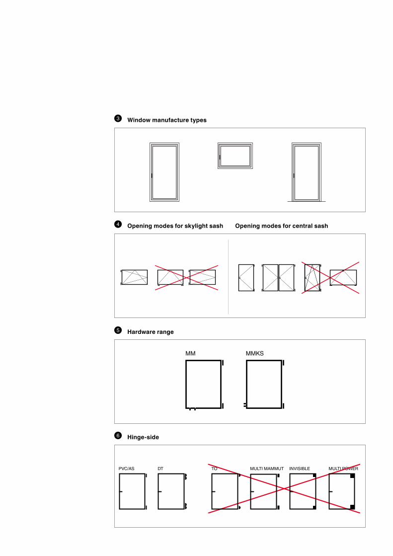
MM MMKS
MULTI MAMMUT INVISIBLE MULTI POWERTOPVC/AS DT
3 Window manufacture types
4 Opening modes for skylight sash Opening modes for central sash
5 Hardware range
6 Hinge-side

= 30 kg
600 - 1300 mm
500 - 800 mm
600 - 1300 mm
500 - 800 mm≤600-1300mm
8 Application range for skylight sash
7 Maximum sash weight for skylight
≤500-800mm

12/18-13
12/20-13
4/18-13
12/18-9
12/20-9
4/15-9
4/18-9
9 Sashprofile-airgap,rebatelegandoffset
10 Fitting groove Thefittinggroovemustbecreatedaccordingtothespecificationsinourprintandonline
catalogues.

FT30
FT24 FT18
FT20
36 4
3-5
34 -
38
36 4
43 -
48
34 -
38
43 -
48
3-5
11 Frame rebate
12 Transomprofile
See also page 15

≤ 15 Nm
≤ 10 Nm
13 Handle operation
14 Application diagram Forthecentralsash,therelevantapplicationdiagramapplies,dependingonthe
hinge-sideused,andmustbeobserved.Furtherinformationcanbefoundinthe corresponding assembly instructions.
There is no individual application diagram for the skylight sash. The maximum sizes and the maximum sash weight must be observed.
All notes regarding the use of application diagrams in our print and online catalogues must betakenintoaccount.
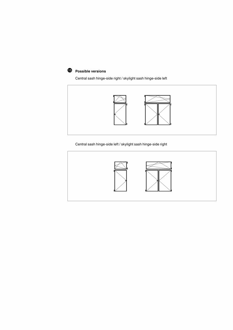
15 Possible versions
Centralsashhinge-sideright/skylightsashhinge-sideleft
Centralsashhinge-sideleft/skylightsashhinge-sideright
1
2
3
4
5
6
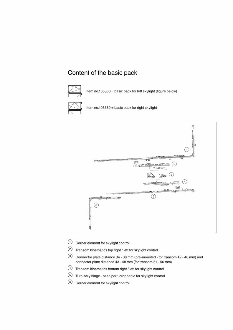
Itemno.105360=basicpackforleftskylight(figurebelow)
Itemno.105359=basicpackforrightskylight
Contentofthebasicpack
1 Cornerelementforskylightcontrol2 Transomkinematicstopright/leftforskylightcontrol3 Connector plate distance 34 - 38 mm (pre-mounted - for transom 42 - 46 mm) and
connector plate distance 43 - 48 mm (for transom 51 - 56 mm)4 Transomkinematicsbottomright/leftforskylightcontrol5 Turn-onlyhinge-sashpart,croppableforskylightcontrol6 Cornerelementforskylightcontrol

Hardware combinationOverviewofthecentralsashandskylightsash
Seefollowingpageforitemlistsfortheskylightsash
The hardware combination of the central sash corresponds to the combination of a 1-sashed turn-only window except for the upper corner element and the turn-only hinge faceplate. The corner element and the turn-only hinge faceplate are partofthebasicpackfortheskylight.
The corresponding assembly instructions for the central lockingsystemandthehinge-sideusedmustbeobserved.
Basicpackfortheskylightsash(seepreviouspage)
12
34
5
6
37
8
9
11
3
10
4
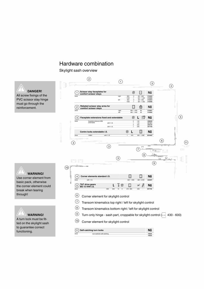
WARNING!Use corner element from basicpack,otherwisethe corner element could breakwhentearingthrough!
WARNING!Aturnlockmustbefit-tedontheskylightsashto guarantee correct functioning.
T&T drive gearsBS 15 VHH i.S.
silver 800 640 15 0 470 - 800 200 - 201746
5
Faceplate extensions fixed and extendablesilver faceplate extension MM,
extendable0 140 206630
0411.S.i 1with 2018410 235 206197
5321 201750.S.i 1with
3
Corner elements standard i.S.silver with 1 i.S. 320 - 1.650 360 - 2.450 222201
4
Rebated scissor stay arms forcomfort scissor stays
silver right 490 - 1.400 80 215051left 490 - 1.400 80 215052
2
Scissor stay faceplates forcomfort scissor stays
silver right 800 0 601 - 800 2150531050 1 801 - 1.050 215055
left 800 0 601 - 800 2150541050 1 801 - 1.050 215056
1
Self-catching turn lockssilver turn-restrictor self-catching 10534
10535
11
DANGER!AllscrewfixingsofthePVC scissor stay hinge must go through the reinforcement.
Hardware combinationSkylightsashoverview
6 Cornerelementforskylightcontrol7 Transomkinematicstopright/leftforskylightcontrol8 Transomkinematicsbottomright/leftforskylightcontrol9 Turn-onlyhinge-sashpart,croppableforskylightcontrol( 430 - 600)
10 Cornerelementforskylightcontrol
Centre locks extendable i.S.silver 1280V with 1 i.S. 1 470 801 - 1.280 2018401

A
C
C
A
BB
206
206 150120 13,5
4
8,527
36
44
92
Installingthefittingsontheframe
Routing pattern for transom kinematics 12L
Routing pattern for transom kinematics (timber example)
Top (view A)
Bottom (view B)
Section C-C
*Drill hole for emergency opening with handle, if desired.
*

36 4
3-5
34 -
38
36 4
43 -
48
34 -
38
43 -
48
3-5
36 4
3-5
34 -
38
36 4
43 -
48
34 -
38
43 -
48
3-5
CAUTION!In the case of rebate depths of less than 40 mm tothecentreseallevel,werecommend that the top kinematicsarealsosealedwith silicon.
WARNING!The limit dimensions for the plate distance of 34 - 38 mm or 43 - 48 mm must not be exceeded or undershot in any circumstances. Otherwise the function is no longer guaranteed.
Installingthefittingsontheframe

290
322,5
12,5
17
158
125,5
Ø3
Ø3
12,5
17
290
322,5
12,5
17
158
125,5
Ø3
Ø3
12,5
17Installingthefittingsontheframe
Drilling-hole pattern for transom kinematics 12L
Top
Bottom
1
1
1
1
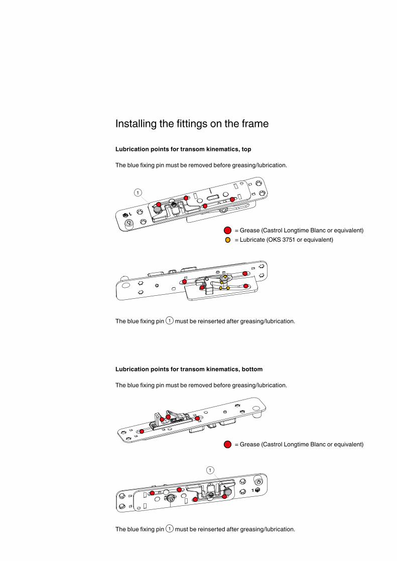
= Grease (Castrol Longtime Blanc or equivalent) = Lubricate (OKS 3751 or equivalent)
= Grease (Castrol Longtime Blanc or equivalent)
Installingthefittingsontheframe
Lubrication points for transom kinematics, top Thebluefixingpinmustberemovedbeforegreasing/lubrication.
Thebluefixingpin 1 must be reinserted after greasing/lubrication.
Lubrication points for transom kinematics, bottom Thebluefixingpinmustberemovedbeforegreasing/lubrication.
Thebluefixingpin 1 must be reinserted after greasing/lubrication.

1
2 3
Installingthefittingsontheframe
Installing the kinematics components
1. Inserttoptransomkinematics 1 intoroutingandsecurewithscrews(fullthread), min. Ø 4 x 30 mm.
2. Selectconnectorfortransomkinematics 2 accordingtotransomprofile(seepage11)andscrewontothebottomtransomkinematicsinthecorrectlocationandposition(notch).
3. Insertbottomtransomkinematics 3 intoroutingandsecurewithscrews(fullthread), min. Ø 4 x 30 mm.
IMPORTANT!Thescrewfixingofthetoptransomkinematics must go through the reinforcement.

Installingthefittingsontheframe
Timber installation example
PVC installation example
115
150
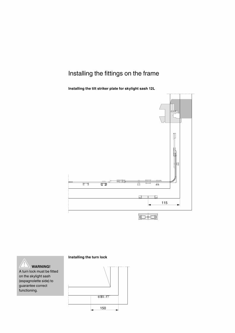
Installingthefittingsontheframe
Installing the tilt striker plate for skylight sash 12L
Installing the turn lock
WARNING!Aturnlockmustbefittedontheskylightsash (espagnolette side) to guarantee correct functioning.
1
2
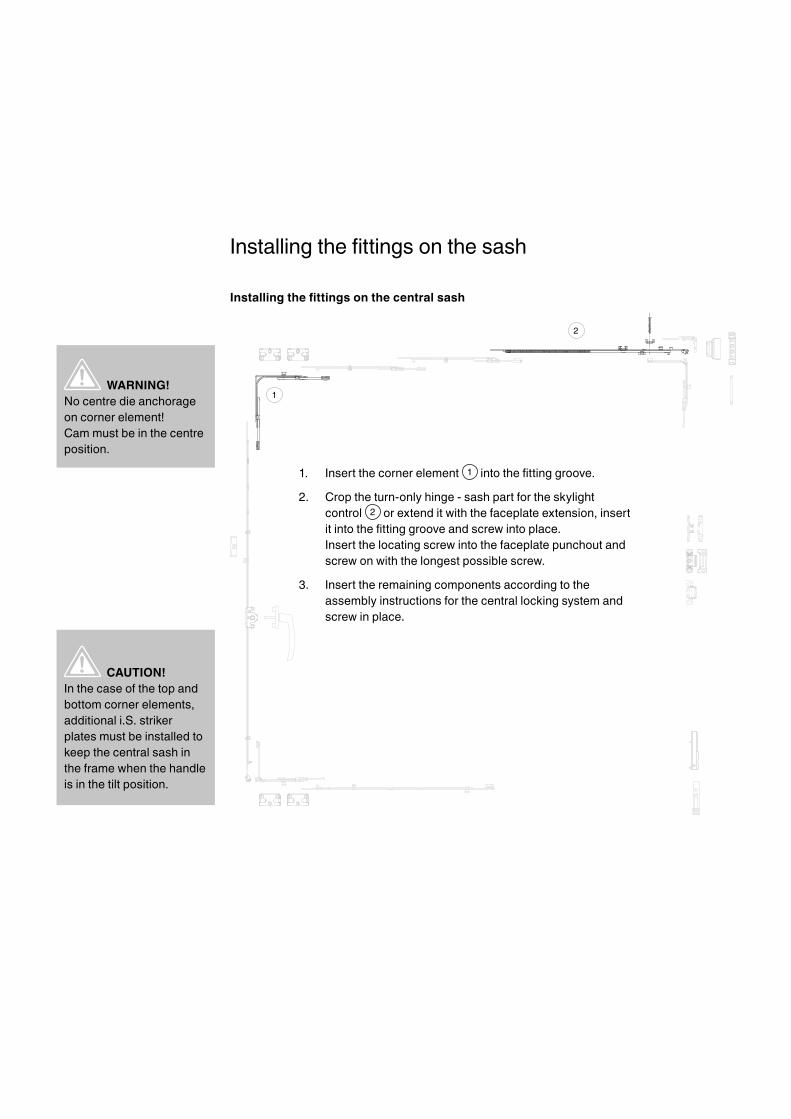
WARNING!No centre die anchorage on corner element!Cam must be in the centre position.
CAUTION!In the case of the top and bottomcornerelements,additionali.S.striker plates must be installed to keepthecentralsashinthe frame when the handle is in the tilt position.
Installingthefittingsonthesash
Installingthefittingsonthecentralsash
1. Insert the corner element 1 intothefittinggroove.
2. Croptheturn-onlyhinge-sashpartfortheskylight control 2 orextenditwiththefaceplateextension,insertitintothefittinggrooveandscrewintoplace. Insert the locating screw into the faceplate punchout and screw on with the longest possible screw.
3. Insert the remaining components according to the assemblyinstructionsforthecentrallockingsystemandscrew in place.
12
3
4
5
6
Installingthefittingsonthesash
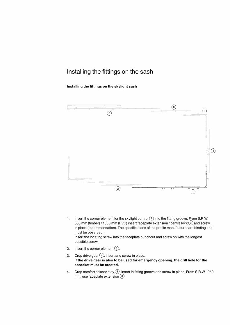
Installingthefittingsontheskylightsash
1. Insertthecornerelementfortheskylightcontrol 1 intothefittinggroove.FromS.R.W.800mm(timber)/1000mm(PVC)insertfaceplateextension/centrelock 2 and screw inplace(recommendation).Thespecificationsoftheprofilemanufacturerarebindingandmust be observed. Insert the locating screw into the faceplate punchout and screw on with the longest possible screw.
2. Insert the corner element 3 .
3. Crop drive gear 4 ,insertandscrewinplace. If the drive gear is also to be used for emergency opening, the drill hole for the sprocket must be created.
4. Crop comfort scissor stay 5 ,insertinfittinggrooveandscrewinplace.FromS.R.W1050mm,usefaceplateextension 6 .

WARNING!Both centre die anchorages must be removed to guarantee correct functioning.
Hinging the sash in the frame
Thecentralsashandtheskylightsasharehingedintheframeaccordingtotheassembly instructions of the hinge-side used.
Removing the centre die anchorage from the skylight kinematics
Pullfixingpinbehindtheconnectorforkupwards/downwards.

1
2
3
Tearingthroughthecentrallockingsystem
1. Tearthroughthecentrallockingsystemofthecentralsash 1 .
2. Ensurethatthefixingpinsinthetopandbottomkinematics 2 have been removed (see page 23).
3. Tearthroughthecentrallockingsystemoftheskylightsash 3 if possible via drill hole for emergency opening. Otherwise tear through with the handle on the central sash.
2 mm
4
+-
- +
1
2
3
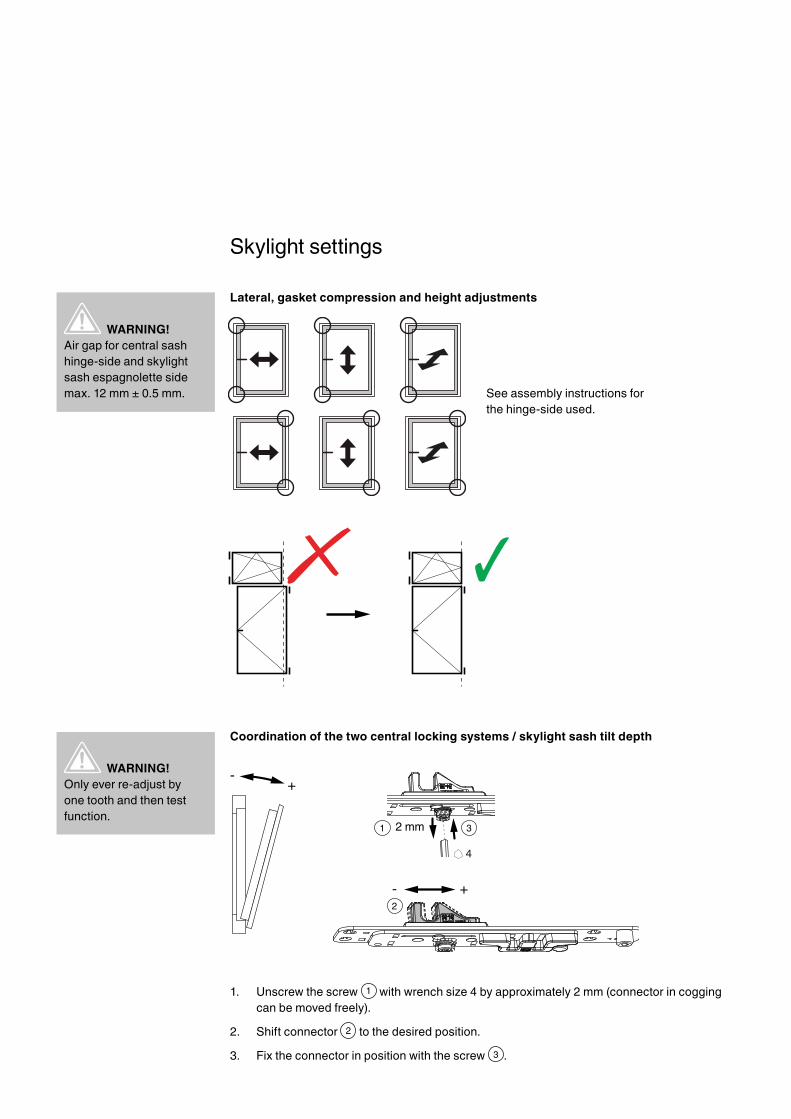
WARNING!Only ever re-adjust by one tooth and then test function.
WARNING!Air gap for central sash hinge-sideandskylightsash espagnolette side max. 12 mm ± 0.5 mm.
Skylightsettings
Lateral, gasket compression and height adjustments
See assembly instructions for the hinge-side used.
Coordination of the two central locking systems / skylight sash tilt depth
1. Unscrew the screw 1 with wrench size 4 by approximately 2 mm (connector in cogging can be moved freely).
2. Shift connector 2 to the desired position.
3. Fix the connector in position with the screw 3 .
1
1
Skylightsettings
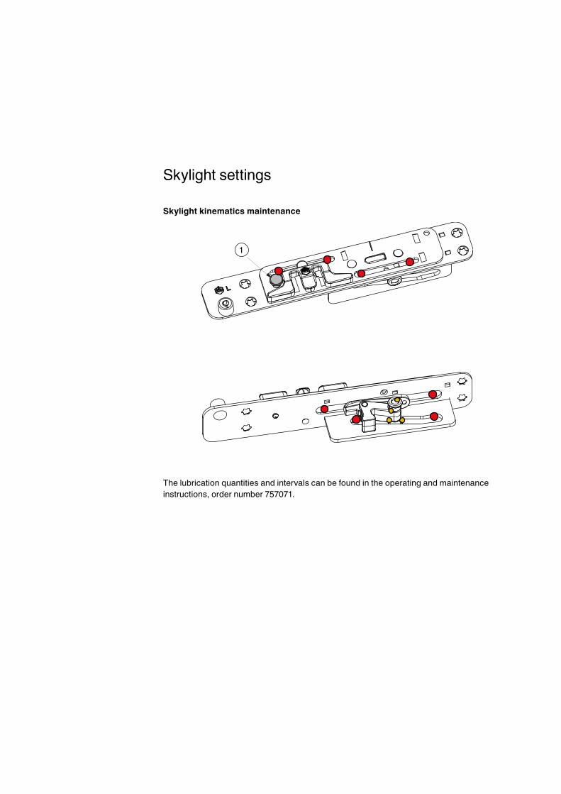
Skylight kinematics maintenance
The lubrication quantities and intervals can be found in the operating and maintenance instructions,ordernumber757071.

Notes
MACO MULTI-MATIC
MAYER & CO BESCHLÄGE GMBH
Alpenstraße 173A-5020 Salzburg
Tel.: +43 662 6196-0E-Mail: [email protected]
www.maco.eu
Order no. 757334EN – Date: August 2016Date changed: September 2017
All rights reserved and subject to change.
This print document is revised regularly.The latest version is available at
http://www.maco.eu/sites/assets/MacoDocs/757334/757334en.pdf or scan the QR code.
Satisfied?We appreciate your [email protected]


