All text and images contained in this document are proprietary and may not be shared, modified, distributed, reproduced, or reused without the express written permission of EZ-ACCESS.
17838 REV 08-09-18
Assembly Manual
GATEWAY™ 3G Solid Surface Portable Ramp Available with or without handrail options
Ramp Only
Ramp w/ Two-line Handrails Ramp w/ Handrails and Vertical Pickets
-2-
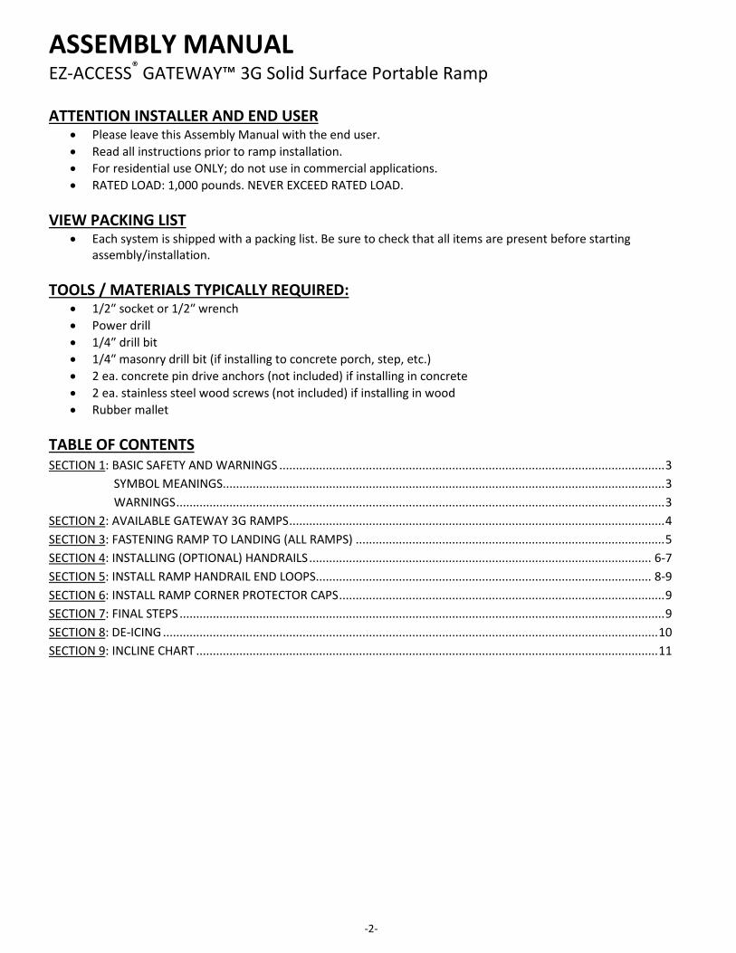
ASSEMBLY MANUAL EZ-ACCESS® GATEWAY™ 3G Solid Surface Portable Ramp ATTENTION INSTALLER AND END USER
• Please leave this Assembly Manual with the end user. • Read all instructions prior to ramp installation. • For residential use ONLY; do not use in commercial applications. • RATED LOAD: 1,000 pounds. NEVER EXCEED RATED LOAD.
VIEW PACKING LIST
• Each system is shipped with a packing list. Be sure to check that all items are present before starting assembly/installation.
TOOLS / MATERIALS TYPICALLY REQUIRED:
• 1/2″ socket or 1/2″ wrench • Power drill • 1/4″ drill bit • 1/4″ masonry drill bit (if installing to concrete porch, step, etc.) • 2 ea. concrete pin drive anchors (not included) if installing in concrete • 2 ea. stainless steel wood screws (not included) if installing in wood • Rubber mallet
TABLE OF CONTENTS SECTION 1: BASIC SAFETY AND WARNINGS .................................................................................................................... 3
SYMBOL MEANINGS..................................................................................................................................... 3 WARNINGS ................................................................................................................................................... 3
WARNING SYMBOL: This symbol may appear in various colors and in conjunction with other symbols. The WARNING symbol indicates that a failure to obey the warning could result in property damage, damage to equipment, serious personal injury, or death, as well as the serious personal injury or death of others.
NOTE SYMBOL: This symbol may appear in various colors and in conjunction with other symbols. This indicates that a failure to obey all notes could result in improper operation, less than optimum performance, and at the sole discretion of the manufacturer, may void your warranty.
1.2. WARNINGS RATED LOAD: 1,000 pounds. NEVER EXCEED RATED LOAD. Professional installation is recommended. Use ramp only with a qualified helper. Avoid dragging ramp as damage will occur. Always exercise caution when using a ramp. Use ramp only if top lip transition plate and lower transition plate are properly supported by
level, stable, and structurally sufficient surfaces. Use only if sufficient maneuvering room is available at both ends of the ramp to assure safe
travel when entering and exiting the ramp. Ramp will conduct heat. Do not place on or near open flame or hot objects as burns may result
when using or handling. If ramp is exposed to heat, hot weather or direct sunlight, use gloves when handling. Ramps reflect light. Use sunglasses, reposition ramp, or paint walking surface with flat-finish
light grey metal primer to minimize unsafe glare during use (use of darker paint/primer will increase heat buildup of ramp during warm climatic conditions).
Use only if ice, snow, wet leaves and/or other debris (that may decrease traction and increase the risk of slipping) have been removed from ramp.
Moisture on the ramp surface will decrease traction and increase the risk of slipping. Use extreme caution when wet.
If angle or traction conditions are unsafe, DO NOT USE ramp! Inspect ramp regularly for any damage, including bending and cracked or broken welds. If any
part of the ramp is unstable, damaged, or otherwise defective, DO NOT USE and call your dealer.
Aluminum conducts electricity. Do not use or handle ramp around live wiring or during electrical storms.
This ramp is intended only for residential use for people and mobility equipment only. Always use your mobility equipment’s lap belt. Do not run, jump or play on or around ramp, including climbing on or between the handrails. Do not use handrails or ramp to support planters, decorations, lights, etc. It is important you refer to your equipment's (wheelchair or scooter) owner manual for the
proper degree of incline/decline and chair direction before using ramp. Never exceed your mobility equipment manufacturers recommendations.
If any part of the ramp is damaged or loose, do not use until repairs can be made by a certified installer or other qualified person. Contact your dealer or reseller for more information.
Read and follow all safety and operating instructions provided by the manufacturer of the equipment.
Ramps in freezing temperatures will readily freeze any moisture on the walking surface thereby increasing the risk of slipping, use extreme caution.
Use only if supporting surfaces are capable of supporting , at minimum, the same rated load as the ramp (1,000 lbs.).
-4-
2. AVAILABLE GATEWAY 3G RAMPS 2.1. The EZ-ACCESS® GATEWAY™ 3G Solid Surface Portable Ramp (also referred to as ‘GATEWAY 3G
Ramp’ or ‘ramp’ throughout this manual) is available in 3’, 4’, 5’, 6’, 7’, 8’, 9’, and 10’ lengths. All ramps come with 1 self-adjusting lower transition plate, 1 fixed top lip transition plate, 4 side rail protective caps, and 2 clevis pins.
The 3’-8’ ramp lengths come standard with 2” curbs; 9‘ and 10’ lengths come standard with 4” curbs.
2.2. GATEWAY 3G Ramp Only (FIG. 1) includes: 2.2.1. Ramp
2.3. GATEWAY 3G Ramp with Two-line Handrails (FIG. 2) includes: 2.3.1. Ramp, handrails with lower rail, end brackets, and end loops
2.4. GATEWAY 3G Ramp with Handrails with Vertical Pickets (FIG. 3) includes: 2.4.1. Ramp, handrails with picketed insert, end brackets, and end loops
FIG. 1 FIG. 2 FIG. 3
-5-
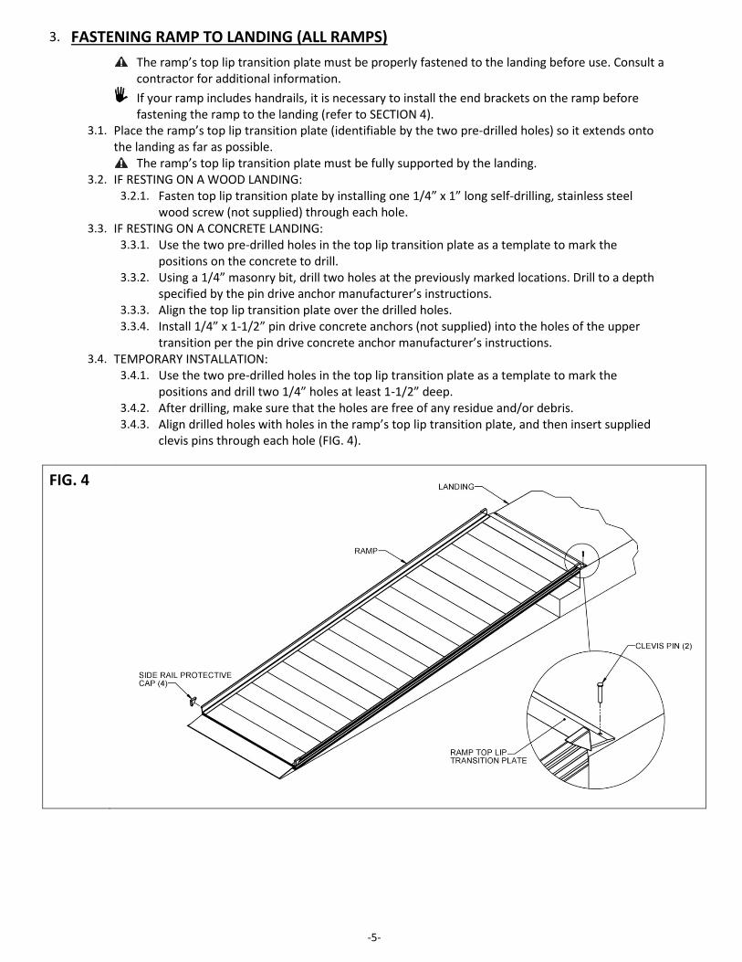
3. FASTENING RAMP TO LANDING (ALL RAMPS) The ramp’s top lip transition plate must be properly fastened to the landing before use. Consult a
contractor for additional information. If your ramp includes handrails, it is necessary to install the end brackets on the ramp before
fastening the ramp to the landing (refer to SECTION 4). 3.1. Place the ramp’s top lip transition plate (identifiable by the two pre-drilled holes) so it extends onto
the landing as far as possible. The ramp’s top lip transition plate must be fully supported by the landing.
3.2. IF RESTING ON A WOOD LANDING: 3.2.1. Fasten top lip transition plate by installing one 1/4” x 1” long self-drilling, stainless steel
wood screw (not supplied) through each hole. 3.3. IF RESTING ON A CONCRETE LANDING:
3.3.1. Use the two pre-drilled holes in the top lip transition plate as a template to mark the positions on the concrete to drill.
3.3.2. Using a 1/4” masonry bit, drill two holes at the previously marked locations. Drill to a depth specified by the pin drive anchor manufacturer’s instructions.
3.3.3. Align the top lip transition plate over the drilled holes. 3.3.4. Install 1/4” x 1-1/2” pin drive concrete anchors (not supplied) into the holes of the upper
transition per the pin drive concrete anchor manufacturer’s instructions. 3.4. TEMPORARY INSTALLATION:
3.4.1. Use the two pre-drilled holes in the top lip transition plate as a template to mark the positions and drill two 1/4” holes at least 1-1/2” deep.
3.4.2. After drilling, make sure that the holes are free of any residue and/or debris. 3.4.3. Align drilled holes with holes in the ramp’s top lip transition plate, and then insert supplied
clevis pins through each hole (FIG. 4).
FIG. 4
-6-
4. INSTALLING (OPTIONAL) HANDRAILS
If ramp does not include optional handrails, skip to SECTION 6. 4.1. Both handrail styles – two-line and handrails with vertical pickets – come pre-assembled. Regardless of
the style, the process of attaching handrails to the ramp is the same. 4.2. Turn the ramp section upside down on a flat surface (do this on cardboard or a lawn so that the ramp is
not damaged). 4.3. Locate 4 end brackets (these will be used to attach handrails in a later step) as shown in FIG. 5. One end
bracket will be installed on each corner of the ramp. 4.4. Slide the upper lip of the end bracket into the groove in the ramp side rail (FIG. 5).
4.4.1. Secure end bracket to the ramp by aligning the innermost hole of the end bracket over the threaded insert on the ramp.
4.4.2. Insert one 5/16″-18 x 1-1/2″ bolt and 5/16″-18 washer per bracket, and tighten securely with 1/2” socket or wrench.
4.5. After all 4 brackets are installed and secured, turn the ramp to its upright position, being careful not to damage the studs.
4.5.1. Secure ramp to the landing (refer to SECTION 3) before continuing to install handrails.
FIG. 5
-7-
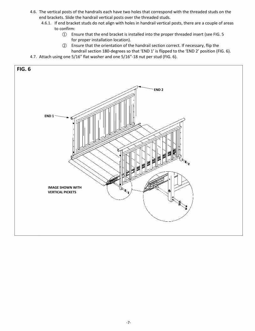
4.6. The vertical posts of the handrails each have two holes that correspond with the threaded studs on the end brackets. Slide the handrail vertical posts over the threaded studs.
4.6.1. If end bracket studs do not align with holes in handrail vertical posts, there are a couple of areas to confirm:
① Ensure that the end bracket is installed into the proper threaded insert (see FIG. 5 for proper installation location).
② Ensure that the orientation of the handrail section correct. If necessary, flip the handrail section 180-degrees so that ‘END 1’ is flipped to the ‘END 2’ position (FIG. 6).
4.7. Attach using one 5/16″ flat washer and one 5/16″-18 nut per stud (FIG. 6). FIG. 6
IMAGE SHOWN WITH VERTICAL PICKETS
END 1
END 2
-8-
5. INSTALL RAMP HANDRAIL END LOOPS
If ramp does not include optional handrails, skip to SECTION 6. 5.1. Ramps ordered with optional handrails – two-line and handrails with vertical pickets – feature end loops
which are added at both the upper and lower ends of the handrail (FIG. 7). 5.1.1. FIG. 7 shows loops installed on a two-line handrail; however, the installation process is the
same for both handrail styles. 5.1.2. There are two loop sizes: The upper loop is used on the top of a ramp handrail section and
is the larger of the two sizes; the lower loop is slightly smaller and is used on the bottom of the ramp handrail section. Upper/lower loops are not interchangeable but are installed in the same manner.
5.1.3. FIG. 8 (upper loop) and FIG. 9 (lower loop) show the difference between each loop.
FIG. 7
FIG. 8
UPPER END LOOP IDENTIFICATION: • THE ATTACHMENT PLATE ON THE UPPER END LOOP ANGLES IN,
TOWARD THE LOOP BEND. • ALSO, THE DISTANCE BETWEEN THE TUBE BEND AND THE END
LOOP ATTACHMENT PLATE IS LONGER THAN ON THE LOWER END LOOP.
FIG. 9
LOWER END LOOP IDENTIFICATION: • THE ATTACHMENT PLATE ON THE LOWER END LOOP ANGLES
OUT, AWAY FROM THE LOOP BEND. • ALSO, THE DISTANCE BETWEEN THE TUBE BEND AND THE
ATTACHMENT PLATE IS SHORTER THAN ON THE UPPER END LOOP
FOR REFERENCE, THE TOP OF THE RAMP HAS ANCHORING HOLES IN THE TRANSITION PLATE.
-9-
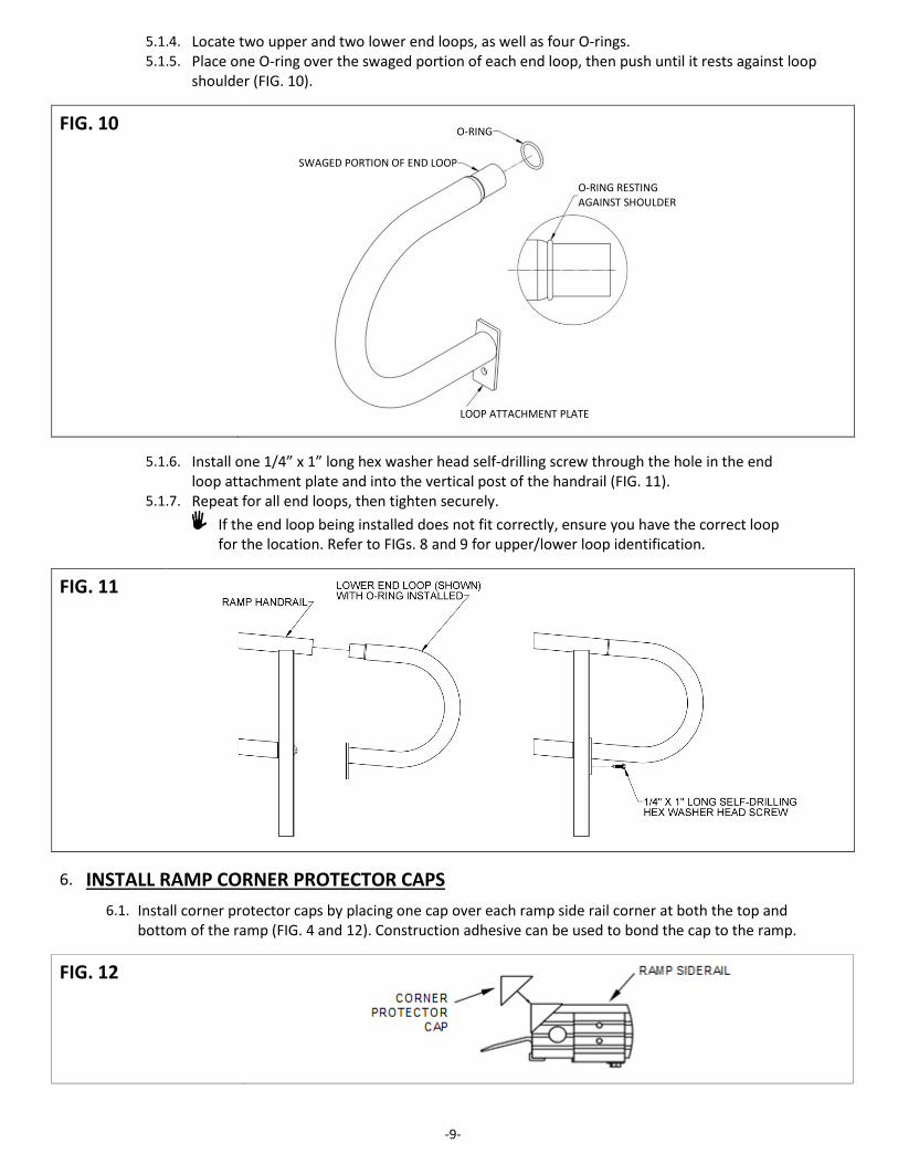
5.1.4. Locate two upper and two lower end loops, as well as four O-rings. 5.1.5. Place one O-ring over the swaged portion of each end loop, then push until it rests against loop
shoulder (FIG. 10).
FIG. 10
5.1.6. Install one 1/4” x 1” long hex washer head self-drilling screw through the hole in the end
loop attachment plate and into the vertical post of the handrail (FIG. 11). 5.1.7. Repeat for all end loops, then tighten securely.
If the end loop being installed does not fit correctly, ensure you have the correct loop for the location. Refer to FIGs. 8 and 9 for upper/lower loop identification.
FIG. 11
6. INSTALL RAMP CORNER PROTECTOR CAPS 6.1. Install corner protector caps by placing one cap over each ramp side rail corner at both the top and
bottom of the ramp (FIG. 4 and 12). Construction adhesive can be used to bond the cap to the ramp.
FIG. 12
O-RING
SWAGED PORTION OF END LOOP
O-RING RESTING AGAINST SHOULDER
LOOP ATTACHMENT PLATE
-10-
7. FINAL STEPS 7.1. TOUCH-UP ARCHITECTURALLY FINISHED HANDRAILS:
7.1.1. Use sandpaper (180 grit or equivalent) for touching up scratches on architecturally finished handrails.
7.1.2. Sand in direction of the grain as shown (FIG. 13). Do NOT use on painted or powder coated surfaces.
7.2. FINAL CHECKS: 7.2.1. Ensure that all fasteners are in place and secure. 7.2.2. Walk on the assembled system, checking for any undue
movement. 7.2.3. Ensure that the level and slope has not shifted during
installation. 7.2.4. Check that all handrail ends are covered (either with loops
or with end caps).
FIG. 13
8. DE-ICING
For the safety of all users, it is important to keep your system clear of snow, ice, and other debris. Always follow the deicing agent manufacturer’s directions. EZ-ACCESS will not be held responsible for any injuries or damages that arise from the information
provided. ALWAYS check with the deicing product’s manufacturer or your local supplier to determine which method is best for your situation.
Sodium Chloride (salt) and Calcium Chloride are particularly damaging to newly poured concrete. In addition, these chemicals should not be applied to brick and stone surfaces.
While care has been taken to ensure that the table below is accurate, the information shown is not all-inclusive. Manufacturers of deicing products may make changes to their products as well as recommended functions and usage requirements. The deicing method you choose should be researched with your deicer supplier so you can determine which method is best for your situation.
The information below is taken from Fact Sheet 707, Cooperative Extension Service, University of Maryland at College Park, University of Maryland Eastern Shore and was up-to-date at the time of this manual’s publication.
PRODUCT MIN. WORKING TEMP (oF)
SPEED OF ACTION
DAMAGES CONCRETE AND METALS?
HARMFUL TO PLANTS?
MAGNESIUM CHLORIDE -13 VERY FAST NO MODERATE CALCIUM CHLORIDE 5 FAST YES YES SODIUM CHLORIDE (SALT) 18 MODERATE YES YES
POTASSIUM CHLORIDE 25 SLOW OK ON OLD CONCRETE MODERATE
CALCIUM MAGNESIUM ACETATE (CMA) 25 SLOW NO NO
-11-
9. INCLINE CHART
IMPORTANT: Refer to your mobility equipment manufacturer for the proper degree of incline/decline and chair direction before attempting ramp use. Never exceed your mobility equipment manufacturer recommendations.
TO ESTABLISH THE PROPER RAMP LENGTH:
Determine the incline that your chair is designed to climb. Measure the rise (distance from the top step, porch, van, etc. to
the ground). Refer to Incline Chart to find proper ramp length. At any incline, use ramp only with a qualified helper.