simple procedure for the ASSEMBLY OF BENDER ELEMENTS Prepared by: Claudia Festa Angel Palomino Tae Sup Yun Jong Sub Lee Minsu Cha Particulate Media Research Laboratory - Georgia Institute of Technology
Transcript
simple procedure for the
ASSEMBLY OF BENDER ELEMENTS
Prepared by:
Claudia Festa
Angel Palomino
Tae Sup Yun
Jong Sub Lee
Minsu Cha
Particulate Media Research Laboratory - Georgia Institute of Technology
Bender element types
SERIES TYPEEXTERNAL PLATES
INTERNAL PLATE
PIEZO CERAMIC
PLATES
POLARIZATION
DIRECTION
PARALLEL TYPE
POLARIZATION
DIRECTION
EXTERNAL PLATES
INTERNAL PLATE
PIEZO CERAMIC
PLATES
INTERNAL PLATE
SOLDING SITE
Devices and materials
1. Soldering iron and accessories
2. Soldering flux
3. Coaxial cable
4. Epoxy
5. Multimeter
6. Silver conductive paint
7. Heat-shrink tubing
8. Nylon flat point socket screw
9. Polyurethane
Preparation
Remove outer shield from one end of coaxial cable. Separate the inner core from the copper mesh. Remove the end of inner core shield. If making a parallel BE, divide the copper mesh into two branches.
Coat the ends of the cable and the BE with soldering flux.
Preparation
If making a series type BE, solder the core to one external plate and the copper mesh to the other one.
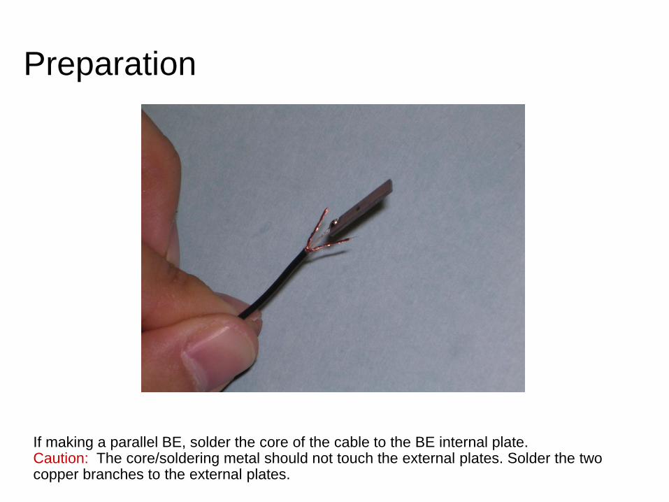
Preparation
If making a parallel BE, solder the core of the cable to the BE internal plate. Caution: The core/soldering metal should not touch the external plates. Solder the two copper branches to the external plates.
Check connections
Check the circuits with a multimeter. The core-to-shield resistance must be infinite (open circuit).
Coating
Water-proof the BE by coating the BE and the exposed portion of the cables with low viscosity polyurethane. Be sure to coat all BE faces, including the edges. Allow the polyurethane to dry with the BE in the upright position. A second coat may be applied if needed.
An electric shield is needed to prevent cross talk phenomena (critical in wet soils – Parallel bender elements are “self-grounded”). Spread a layer of silver conductive paint over the surfaces of the coated bender element. The conductive paint must contact the shield in the coaxial cable, i.e., ground.
Electric shield
Cable reinforcement
Reinforce the connections using heat-shrink tubing. Shrink the tube using a hair dryer. May use more than one shrink-tube layers.
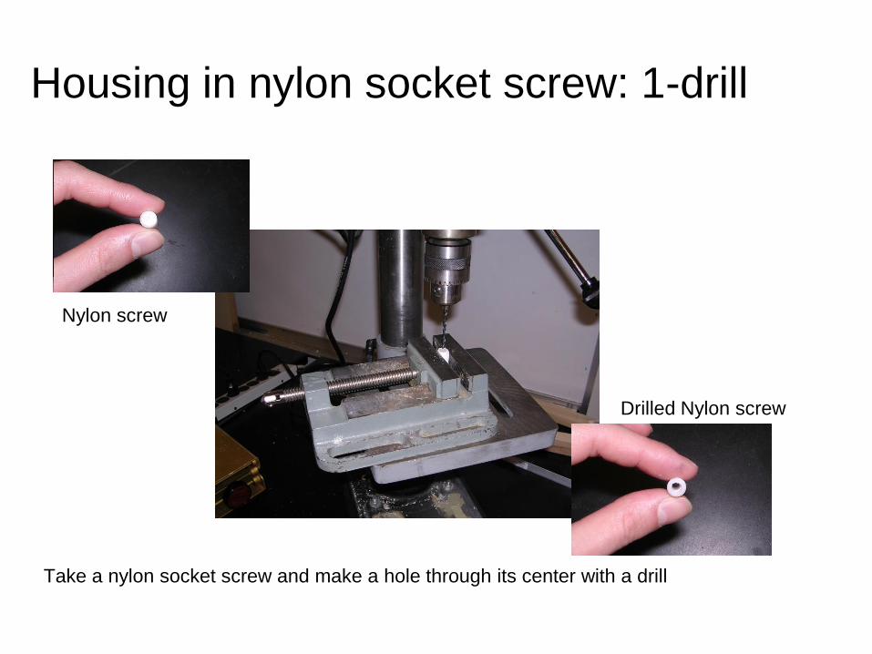
Housing in nylon socket screw: 1-drill
Take a nylon socket screw and make a hole through its center with a drill
Nylon screw
Drilled Nylon screw
Slide the BE into the hole inside the nylon screw. Fill in the air gap between the BE assembly and the screw with epoxy.
Housing in nylon socket screw: 2-fix
Done !
The BE assembly is ready for use once the epoxy has cured. The threaded nylon screw housing can be conveniently installed in any geotechnical cell, and easily replaced in case of malfunction.
Components and Possible Vendors Piezoelectric transducer
APC www.americanpiezo.com
PIEZO SYSTEMS, INC. www.piezo.com
PIEZOTECHNOLOGY www.piceramic.com
Parallel type recommended (lower cross-talk, self-shielding)