Page 1
Assertion Based Functional Verification of March
Algorithm Based MBIST Controller
A MASTER’S THESIS
Submitted
in the partial fulfillment of the requirements for the award of the degree
Of
MASTER OF TECHNOLOGY
In
INFORMATION TECHNOLOGY
(Specialization in MICROELECTRONICS)
Submitted by
Ashwani Kumar
Under the Guidance of
Dr. Kusum Lata
Faculty (Electronics Dept.)
IIIT-Allahabad
INDIAN INSTITUTE OF INFORMATION TECHNOLOGY
ALLAHABAD – 211012 (INDIA)
Page 2
Assertion Based Functional Verification of March Algorithm Based MBIST Controller
Indian Institute of Information Technology, Allahabad. Page 1
Chapter 1
Introduction
1.1 Motivation
In the present era, the more data dominating applications on System on Chip (SoCs) require
large number of embedded memories. That’s why embedded memories are in focus of
technology scaling. Due to very small geometries, embedded memories are susceptible to
subtle defects [1, 2]. The testing of memories is very crucial because of very low yield of
memories during fabrication. But in case of embedded memories it becomes a tedious task
because of no primary inputs and outputs. For this purpose a MBIST circuitry is added with
memory which make this testing job very comfortable while adding some area over head.
Here, MBIST controller is the core of MBIST architecture [3] that controls the events
sequencing during memory testing that’s why MBIST controller requires more attention
towards its design and functional verification.
In complex IC design, verification takes about 70-80% of the design develop time. This
portion of development time is still increasing for high speed IC design [4]. Further, in the
reuse-based project, main blocks are recycled by using existing designs, making more effort
being shifted from the design stage to the verification stage. In this circumstance, to increase
the efficiency of verification, reducing the time consumption of verification stage, is
therefore crucial to speed up the whole development process. This can be done by parallel
design and verification stages in the design development. That’s why the verification of
MBIST controller is done parallel to its design process. But for functional verification,
traditional simulation-based is good only at validating baseline functionality and it has been
declared insufficient for detecting critical corner-case errors, referred to herein as verification
hot spots[5].
For this reason, an effective method, to increase the observability of the design and to easily
find out and diagnose the design flaws, is keenly needed. Assertion-based verification (ABV)
is such a method, which combines the formal techniques having assertions and the
Page 3
Assertion Based Functional Verification of March Algorithm Based MBIST Controller
Indian Institute of Information Technology, Allahabad. Page 2
simulation based traditional function verification. Here code coverage and functional
coverage metrics can be used to follow the progress and quality of the verification efforts.
Assertion is used to describe the properties that a design should hold or should never hold.
Some properties with time requirements are not easy to be described with Verilog; and
usually needs much more lines of codes with VHDL. There are many standardized assertion
languages such as PSL, System Verilog Assertion (SVA) and assertion libraries such as
OVL, QVL [5] with which the endeavor for describing a design property becomes much
easier and efficient. Recently, SVAs as a set of System Verilog language [6], has been more
extensively used as specification of assertions within the design, enabling the simulator to
check the assertions during simulation.
1.2 Analysis of Previous Work in this Area
Now days, embedded memories are dominating to cover the chip area that’s why become the
focus of technology scaling [1]. Today’s data-dominated multimedia applications require
more memory than ever before. On-chip SRAM memories begin to dominate the chip area
and have become the focus of technology scaling. However, the physical limitations of the
technology scaling jeopardize further progress of microelectronics as scaling results in
process variations.
In present era, embedded memories cover a large area on the chip for complex designs. So it
is one of the most significant step to implement efficient memory testing strategies [2].
MBIST architecture is one solution which automates the memory testing. It also became
necessary to scaling down the embedded memories. The small and fine geometries of
embedded memories make them susceptible to subtle defects which cause the various faults
in memories. That’s why, test patterns generation strategies are chosen carefully to detect the
manufacturing defects. These algorithms are generally includes the March and checkerboard,
varied pattern backgrounds and others.
The MBIST architecture consists of three main blocks controller, pattern generator and
signature analyzer [6]. Controller handles the all events in MBIST. It controls such as the
increment or decrement in address of memory, whether 0s or 1s patterns is going to read or
Page 4
Assertion Based Functional Verification of March Algorithm Based MBIST Controller
Indian Institute of Information Technology, Allahabad. Page 3
write at those addresses. The pattern controller block contains the address, data generator and
some controls to apply the right pattern to right address. It specifically consists a up and
down counter to control the address sequence. Signature analyzer checks whether memory
read out data is equal to original generated data or not. Based on checking result the
particular flag will be asserted to show pass or fail of pattern.
A FSM MBIST controller is implemented using VHDL and XILINX ISE tool [6]. The FSM
defines control signals and shows when one state will proceed to the next state. Each state
has its sub-states. The counter is a key element of MBIST architecture because the up and
down address sequence is design using counter.
The synthesized design is capable in meeting the functional specifications when
implemented in FPGA [6]. For the different patterns, there is a requirement of modification
in pattern generator.
The design of data and read/write controller for MARCH algorithm based MBIST
architecture to test SRAM [7]. The controller is implemented as an FSM BIST using Verilog
HDL to generated test patterns based on MARCH algorithm to detect the SAFs and TFs.
The design is realized by using ALTERA QUARATUS software to generate the RTL
abstraction of controller. The SAFs and TFs can be detected and distinguished by generating
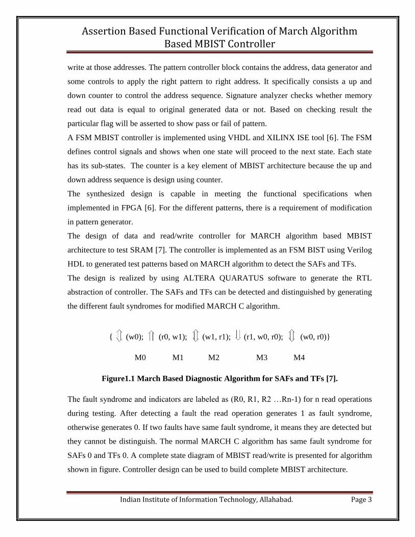
the different fault syndromes for modified MARCH C algorithm.
{ (w0); (r0, w1); (w1, r1); (r1, w0, r0); (w0, r0)}
M0 M1 M2 M3 M4
Figure1.1 March Based Diagnostic Algorithm for SAFs and TFs [7].
The fault syndrome and indicators are labeled as (R0, R1, R2 …Rn-1) for n read operations
during testing. After detecting a fault the read operation generates 1 as fault syndrome,
otherwise generates 0. If two faults have same fault syndrome, it means they are detected but
they cannot be distinguish. The normal MARCH C algorithm has same fault syndrome for
SAFs 0 and TFs 0. A complete state diagram of MBIST read/write is presented for algorithm
shown in figure. Controller design can be used to build complete MBIST architecture.
Page 5
Assertion Based Functional Verification of March Algorithm Based MBIST Controller
Indian Institute of Information Technology, Allahabad. Page 4
Controller design was also presented with simulation results to show the functionality of the
design separately not by considering the issues after its insertion in MBIST architecture.
More number of variations in the fabrication process causes parametric variations in
transistor feature sizes and threshold voltages due to random dopant fluctuations, line edge
roughness, sub-wavelength lithography [8]. Closely matched devices and small transistor
sizes which matter the most when designing SRAM memories, are the first to suffer from the
side-effects of scaling. Random nature of local process variation causes defects to have
random and uniform distribution .This adversely affects the expected system yield. Since
memory is one of the biggest blocks of any system, it is more prone to faults under process
variation.
A failure in memory cell can occur due to these following reasons.
a) An increase in cell access time.
b) Unstable read/write operation.
c) Inability to hold the cell content.
The mismatch in device parameters will increase the probability of these failures.
The modeling and simulation of MBIST architecture for embedded memories as a FSM
design is presented [9]. Verification of architecture is done by testing stuck at faults in
SRAM memory using March C testing algorithm.
The presented MBIST architecture shows the interface connectivity among controller,
pattern generator, address generator and pattern/data comparator clearly with interconnect
signals [10]. Here, the BIST controller is design for dual port SRAM testing MBIST
architecture. BIST controller generates the control signal DGentEN to the data generator to
generate data pattern according to March elements in selected march algorithm, control
signal AGenEN to address generator to ensure the correct address generation for read/write
operation to memory and the control signal DComEN to data comparator. The design
architecture of address generator is explained with its functional behavior required for dual
port SRAM testing. Design Complier from Synopsys Inc. is used to verify the DPMBIST.
The implementation of formal verification techniques for MBIST controller more
specifically, hardwired (as a FSM) memory BIST and programmable (as a micro code
control) memory BIST controllers are considered [12].The formal verification of such
Page 6
Assertion Based Functional Verification of March Algorithm Based MBIST Controller
Indian Institute of Information Technology, Allahabad. Page 5
large controllers is a complex task, than it is tried to simplify this by using the
symbolic model checking, verification of MBIST logic, test cases for controller and
hookup logic, converting the testcases into formal property and module abstraction.
The conversion of test cases into formal properties of the design helps to validate the test
cases which are applied to the design. For example, the validation of the stability condition
begins in any State of controller. If the controller is to satisfy stability condition, it means
controller would not proceed or acquire the next states. If this state is ‘Done’ state of MBIST
controller then this anticipates that controller should never allow the MBIST_Done signal to
be de-asserted. In other words this property shows that FSM of controller should never
transit to state where MBIST_Done signal will be de-asserted.
A five-step method is suggested for the functional verification of digital IC verification using
System Verilog Assertion (SVAs) [15].
(a) List design interfaces.
(b) List the inside functional spots.
(c) List verification requirement for interface.
(d) Formalize the properties with SVA.
(e) Define coverage spots.
The method is demonstrated for the functional verification of a UART RTL Verilog model.
During simulation, the corner cases can be easily checked which are left out in the traditional
functional checking. These are corner cases are tested against the SVAs written to check the
specific property of the design. This is very much possible that these corner cases consists
the bugs in the design but now these design errors can be exposed through the dynamic
simulation output (waveform or log file). Furthermore, by this approach, the assertion
coverage report can be directly used to validate the design and to show the depth of
verification by functional coverage analysis. The suggested five steps increase the
observability of design while designing it. This is feasible for being applied in both the
design process and verification process of RTL model.
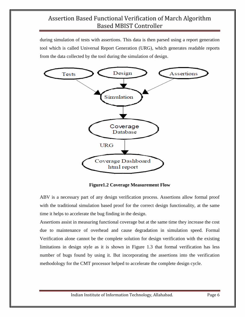
A method which is used to collect the coverage information is shown in Figure1.2 [25].
Coverage information is logged into a database of the tool which is used as a verification tool
Page 7
Assertion Based Functional Verification of March Algorithm Based MBIST Controller
Indian Institute of Information Technology, Allahabad. Page 6
during simulation of tests with assertions. This data is then parsed using a report generation
tool which is called Universal Report Generation (URG), which generates readable reports
from the data collected by the tool during the simulation of design.
Figure1.2 Coverage Measurement Flow
ABV is a necessary part of any design verification process. Assertions allow formal proof
with the traditional simulation based proof for the correct design functionality, at the same
time it helps to accelerate the bug finding in the design.
Assertions assist in measuring functional coverage but at the same time they increase the cost
due to maintenance of overhead and cause degradation in simulation speed. Formal
Verification alone cannot be the complete solution for design verification with the existing
limitations in design style as it is shown in Figure 1.3 that formal verification has less
number of bugs found by using it. But incorporating the assertions into the verification
methodology for the CMT processor helped to accelerate the complete design cycle.
Page 8
Assertion Based Functional Verification of March Algorithm Based MBIST Controller
Indian Institute of Information Technology, Allahabad. Page 7
Figure1.3The distribution of bugs found using assertion checks in formal as well as in
simulation check.
1.3 Problem Definition and Scope
The thesis problem is defined as “Assertion Based Functional Verification of March
Algorithm Based MBIST Controller”.
The parallel verification approach at block level design can be used to implement the
complete MBIST architecture to test the single port SRAM.
The presented approach ensures the correct behaviors of the modules after interfacing with
other modules.
The March C a memory testing algorithm is also modified to test the memory data retention
faults with other memory faults. The design of MBIST controller is also based on this
modified March C algorithm.
1.4 Problem Formulation
This thesis work is divided in to four main parts.
The first part of the work was to design MBIST controller as a verification module using
System Verilog language, for MBIST architecture to test the SRAM.
The second part of the thesis was to learn theory about the verification especially Assertion
based dynamic functional verification, verification plan and system Verilog as assertion
language.
The third part was to make a verification plan for the MBIST controller’s RTL module
design. The verification plan of MBIST controller includes the complete specification
Page 9
Assertion Based Functional Verification of March Algorithm Based MBIST Controller
Indian Institute of Information Technology, Allahabad. Page 8
documentation of MBIST controller, test bench planning, code coverage, functional
coverage, assertions etc.
The fourth part was to implement the verification plan. This includes the simulation using
Synopsys VCS®, generating the coverage metrics, implementation of only required
testcases, analysis of results.
1.5 Thesis Formulation
Chapter 2 of thesis is the introductory chapter of MBIST architecture, MBIST controller and
memory testing March algorithms. It provides the basic idea behind the designed MBIST
controller in this thesis.
Chapter 3 includes the theoretical background of various aspects of verification fields which
are used to verify the design in this thesis work. It comprises the verification technologies,
verification planning and coverage collection.
Chapter 4 describes the tools and languages briefly which are used to complete the thesis
work. The design and verification features are described for Synopsys VCS® as a
verification tool and System Verilog as a language for design and verification both.
Chapter 5, 6, 7 and 8 present my contributions to towards the completion of thesis work.
Chapter 5 represents the implementation of MBIST controller which is based on modified
March C algorithm. Basically the MBIST controller design is based on FSM architecture.
Chapter 6 describes the functional verification of MBIST controller’s HDL code. It includes
the assertion based verification with complete verification planning for MBIST controller
design and its implementation. Chapter 7 shows how to setup the simulation environment for
design and verification of MBIST controller. Chapter 8 contains the functional verification
and simulation results. This chapter also presents the analysis of coverage scores/result for
the different coverage metrics.
Chapter 9 contains the conclusion of thesis work.
Chapter 10 describes the future work and recommendation for the further work on this work.
Page 10
Assertion Based Functional Verification of March Algorithm Based MBIST Controller
Indian Institute of Information Technology, Allahabad. Page 9
Chapter 2
Memory Built in Self-Test (MBIST)
In the present era, the more data dominating applications on System on Chip (SoCs) require
large number of embedded memories having different types and sizes to reduce the
computation time. The effect of this is increased processing speed. That’s why embedded
memories are in focus of technology scaling. Due to very small geometries, embedded
memories are susceptible to subtle defects [1, 2]. To detect these defects, the MBIST
architecture is used for embedded memories testing. The testing of memories is very crucial
because of very low yield of memories during fabrication. In case of embedded memories it
becomes a tedious task because of no primary inputs and outputs to external of SoC. To test
these memories before tape-out of SoC is necessary, this role is done very efficiently by
MBIST architecture. A generic MBIST architecture is shown in Figure2.1. The post
fabrication testing of such memories is very expensive and time consuming because input
and output of such blocks are not easily accessible [3]. The MBIST enables the automatic
testing of embedded memory even without coming in touch with outside test environment.
The implementation of MBIST architecture depends upon the requirement of testing and the
type of memory under test (MUT) for the optimum and efficient testing. BIST technique
integrates the functionality of an automatic test system onto the same die as embedded
memories. Therefore, test pattern generation and response can be performed automatically.
As we know MBIST enables the high speed and high-bandwidth access to the embedded
memory cores [7]. Now days, MBIST is the state-of-the-art technology to test embedded
memory. The main drivers behind the development of MBIST are the high rising cost of
Automatic Test Equipment (ATE) and increase in the complexity of the designs or products.
Sometimes Memory Built-in Self-Test (MBIST) is also referred as Array Built-in Self-Test
(ABIST). This is an amazing piece of logic. Without any direct connection to the outside
world, a very complex embedded memory can be tested efficiently, easily and less costly
unless carefully designed. In present scenario and in coming next years, embedded memories
will be holding most of the silicon area of chip from 60% to 95% [8] in modern SOCs.
Page 11
Assertion Based Functional Verification of March Algorithm Based MBIST Controller
Indian Institute of Information Technology, Allahabad. Page 10
n bit test pattern n bit memory response
next pattern execute
pass/fail
start reject/accept
Figure2.1Generic MBSIT Architecture
In broad sense a MBIST architecture for its typical functionality requires the following the
functional blocks.
i) Pattern Generator: To test the memory, it is necessary to have different data patterns
which would be read & write from and to memory. Data patterns are generated by pattern
generator. The design of pattern generator is based on used pattern type in the selected
algorithm to test the memory. There are various algorithms such as March memory testing
algorithm, checkerboard, varied pattern algorithms etc.
ii) Address generator: Address generator is design to provide the memory addresses to read
and write test pattern on those memory addresses.
iii) Pattern analyzer/comparator: It analyzes the actual data pattern and the data coming
out from the memory after read operation on the memory. Based to the comparison results it
generates the pass/fail signals. If both data patterns match then it generates the pass signal
which means the data coming out from the memory is exactly same as data written in to the
memory. It ensure that memory under test is fault free. But if both data patterns mismatch
then it generates the fail signal this indicates that the data coming out from memory is
Pattern
Generator
Memory
Under Test
Signature/
Pattern
Analyzer
Controller
Page 12
Assertion Based Functional Verification of March Algorithm Based MBIST Controller
Indian Institute of Information Technology, Allahabad. Page 11
different from the actual data written in to the memory. It shows that the memory under test
is faulty.
iv) MBIST controller: This is the heart of MBIST architecture which controls the every
sequence of signals during the memory testing by generating the proper controlling signals.
There are following advantages to implement the MBIST architecture [3].
a) Lower cost of memory testing because it eliminates the need of external and
costly Automatic Test Equipment (ATE).
b) It provides the better fault coverage because the special test patterns are
generated specially for the design under test.
c) A MBIST module can be designed to test the multiple memories at a time or for
parallel testing which is responsible for shorter test time.
d) Due to chip design of MBIST, it can test the memory at the operating frequency
of the system.
e) Testing outside the electrical testing environment.
f) Provides the facility to the consumer to test the circuit or chip before or after
mounting in the other application system boards.
With advantages the implementation of MBIST architecture with memory has few
disadvantages. There are some disadvantages to use the MBIST architecture.
a) Silicon area overhead
b) Increases the power dissipation in system.
c) It reduces the memory access times because of mux logic for MBIST operation
and main operation on memory.
d) Additional pin requirements for the main processor to show the memory testing
results.
e) Checking of the correctness of MBIST circuitry is itself necessary because on
chip testing can also get fail.
Page 13
Assertion Based Functional Verification of March Algorithm Based MBIST Controller
Indian Institute of Information Technology, Allahabad. Page 12
2.1 Introduction to MBIST Controller
A MBIST controller generates the controlling signals based on the memory testing algorithm
to perform the testing operation by MBIST in correct manner. It controls the generation if
data patterns and their generation sequence [9]. For examples, in case of March algorithm it
controls the address generator in such a way that address generator generates the address
sequence in up direction if the coming pattern is generated for up marching. Otherwise
addresses would be generated in down direction if coming pattern is for down marching on
the memory’s addresses. The controller is responsible to start and stop the testing process of
memory. It gets the starting command from top level controller or processor or off chip ATE.
After receiving the command from upper/top level processor, it interacts with other
components of MBIST circuitry such as pattern generator, address generator, comparator and
memory to perform the testing operation in correct manner [10].
Figure2.2A MBIST Architecture with controller, other blocks and their
interconnections.[11]
Page 14
Assertion Based Functional Verification of March Algorithm Based MBIST Controller
Indian Institute of Information Technology, Allahabad. Page 13
The complete MBIST architecture with detailed architectural components is shown in Figure
2.2. The described partition of the MBIST architecture and terms used in Fig 2.2 are not the
standard.
The MBIST controller can be categories in two types mainly.
i) Programmable MBIST controller: Such kind of controller design is based on microcode
control. The controller can be programed according to different algorithms so it is called the
programmable controller. Such controller consist the instruction decoder logic with control
logic. The instruction decoder decodes the instruction written as a program in the memory
other than the MUT. Such controllers are flexible in nature, they can be modified but they
have complex design architecture [3].
ii) Hardwired or FSM type controller: Such controllers have hardwired design means the
architecture cannot be changed once designed. Controller can be design for a particular
algorithm at a time. To modify the controller, complete design has to be restart from the
beginning. The Finite State Machine (FSM) implementation of hardwired designs of
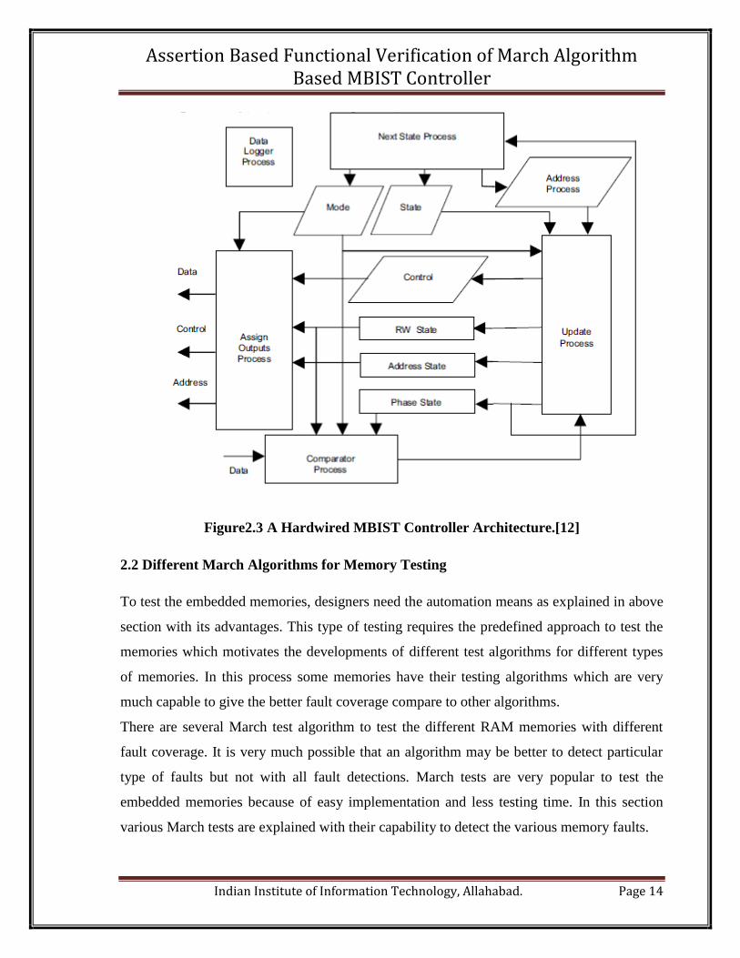
controller such as shown in Figure 2.3 would be easy and economical. As FSM controller
controls the whole MBIST circuitry and defines the correct sequence of events. Different
States of FSM represent the different operations in MBIST circuitry. Every state in FSM has
its sub-states which represents the all events happening at time when controller would in that
state [9]. MBIST architecture based on hardwired or FSM controller has optimum logic
overhead but at the same time its lacks in flexibility. Such type of controller is used to detect
the known faults in memory [12]. It is the oldest MBIST architecture design technique but
still kept developing for the memory testing [3].
Page 15
Assertion Based Functional Verification of March Algorithm Based MBIST Controller
Indian Institute of Information Technology, Allahabad. Page 14
Figure2.3 A Hardwired MBIST Controller Architecture.[12]
2.2 Different March Algorithms for Memory Testing
To test the embedded memories, designers need the automation means as explained in above
section with its advantages. This type of testing requires the predefined approach to test the
memories which motivates the developments of different test algorithms for different types
of memories. In this process some memories have their testing algorithms which are very
much capable to give the better fault coverage compare to other algorithms.
There are several March test algorithm to test the different RAM memories with different
fault coverage. It is very much possible that an algorithm may be better to detect particular
type of faults but not with all fault detections. March tests are very popular to test the
embedded memories because of easy implementation and less testing time. In this section
various March tests are explained with their capability to detect the various memory faults.
Page 16
Assertion Based Functional Verification of March Algorithm Based MBIST Controller
Indian Institute of Information Technology, Allahabad. Page 15
A complete March test comprises the several March elements. Each March element has
sequence of read and writes operations. These operations are applied on each cell of memory
in sequence of March elements in March test [13]. In March test, the memory addresses are
accessed in two directions in upward direction from 0th address to (n-1)th address which
called up marching ( ) in March testing. Other way is down direction from (n-1)th address
to 0th address which is called the down marching indicating by ( ) in Marching testing. A
cell can go under following operations r0, r1, w0, and w1. These symbols indicate the
following operations.
a) r0 : Read ‘0’ as data/pattern value from the memory cell.
b) r1 : Read ‘1’ as data/pattern value from the memory cell.
c) w0 : Write ‘0’ as data/pattern value in to the memory cell.
d) w1 : Write ‘1’ as data/pattern value in to the memory cell.
The boundaries of a complete march test of a March algorithm is delimited by the {….}
brackets while a March element is restricted by the (…) brackets.
Some March test algorithms [12] are listed below. And their complete description with
number of required time cycle and names of faults detected by that particular algorithm are
shown in Table 2.
MATS+: The MATS+ algorithm is shown in Figure 2.4 It comprises only three March
elements.
{ (w0); (r0, w1); (r1, w0)}
M1 M2 M3
Figure2.4 MATS+ March test algorithm with March elements.
Page 17
Assertion Based Functional Verification of March Algorithm Based MBIST Controller
Indian Institute of Information Technology, Allahabad. Page 16
M1, M2 and M3 represent the all three march elements.
March B: The March B algorithm is shown in Figure8. It comprises five March elements
represented by M1, M2, M3, M4 and M5 in Figure2.5.
{ (w0); (r0, w1, r1, w0, r0, w1); (r1, w0, w1); (r1, w0, w1, w0); (r0, w1, w0)}
M1 M2 M3 M4 M5
Figure 2.5 March B test algorithm.
Some other March algorithms are presented in Table 2.1 [13].
Table2.1 March Test Algorithms
In the following Table 2.2 some tests are summarized in term of number of required time
cycle and types of fault detection.
Page 18
Assertion Based Functional Verification of March Algorithm Based MBIST Controller
Indian Institute of Information Technology, Allahabad. Page 17
Table 2.2 Summarized Some March Test Algorithms [14]
Test
Test
Time
Covered Faults
AF SAF TF CFin CFid CFst LCFids
MATS+ 5n A A - - - - -
March
C
10n A A A A A A -
March
B
17n A A A A A A A
In the Table 2.2, n is the number of cells in memory array. A stands for All. AF –Address
decoder faults; SAF- Stuck at Faults; TF –Transition Fault; CFin – Inversion Coupling fault;
CFid–Idempotent coupling faults; CFst – State coupling faults; LCFids – linked Coupling
Faults.
From the above table, it clear that if there is less possibility to has linked coupling faults in
memory than March C test algorithm is much efficient in test time and number of covered
faults.
Page 19
Assertion Based Functional Verification of March Algorithm Based MBIST Controller
Indian Institute of Information Technology, Allahabad. Page 18
Chapter 3
Verification
Verification is the process to check whether the intent of the design is kept while
implementing it. This chapter describes the various aspects of verification process. In the
present era 70-80% design efforts comes under the verification domain. A verification
process takes a large amount of time but it can be reduced by automation of various aspects
of verification process.
3.1 Verification Technologies
Verification process follows two main approaches one is simulation based verification and
another is without simulation called formal verification.
i) Formal Verification: The approach in formal verification is to check the design’s
functionality or correctness based on mathematical models. The formal verification tools
works on the assertions written to check the functionality where assertions represents the
properties of design. Formal verification of complete design is not a feasible task because it
becomes much complex and time consuming. So the formal verification techniques are
applied on the selected modules of complete design and mainly for the corner cases. These
corner cases are not tested during the simulation. In this way formal verification becomes
very effective and less time consuming. Formal Model checking and equivalence checking
are two main approaches used in formal verification.
ii) Simulation Based Verification: Simulation based verification is still the very common
and popular verification technology. In a very simple way a test-bench is used to generate
and apply the test stimulus to verify the design in simulation. Test-bench is also used to fetch
the output from the design corresponding to the applied stimulus. Design which is going to
verified is called the design under verification (DUV). While simulating a design it can
report the presence of bug but it can never assure that design is bug free. For a normal size
Page 20
Assertion Based Functional Verification of March Algorithm Based MBIST Controller
Indian Institute of Information Technology, Allahabad. Page 19
design to apply all possible combinations and sequences of stimuli is tedious and time
consuming task during simulation. That’s the main drawback of simulation verification.
By combining the both approaches the drawbacks of both approaches can be removed. A
different verification approach called Assertion Based dynamic verification.
iii) Assertion Based Dynamic Verification: It is also called assertion based functional
verification (ABV) which includes assertions with simulation and formal techniques to the
traditional simulation based functional verification of the RTL designs [12]. ABV firmly
depends on assertions to verify functionality and observe functional coverage by putting
SVA specifications. Due to this, the verification status is provided by the parallel run of
coverage and assertion checking. By using SVA specifications, there is no need to add tool
specific semantics during verification or writing assertions.
Assertion based verification is now one of the mainstream for functional verification of
designs. The theoretical research to find out new formal methods and industrial practice in
hardware and software verification provides the great benefits to the assertion based
verification [13]. ABV is also a powerful functional verification approach which increases
the efficiency to verify the correct functionality, bug detection and bug removal during the
design process. Assertions are the main elements in the ABV which helps to find out the
untested areas or corner case in the design and to write the better and directed test cases to
test those untested areas. These corner cases may keep bugs which can cause the wrong
functional behavior of design. In this way ABV helps to finds out the bugs present in the
design. It improves the level of verification from RTL to design specifications [14]. ABV
also comprises the coverage property which holds true for a particular functionality if it is
exercised by a test.
This technique can be applied to complete design and the assertion helps to write the directed
test cased or stimuli for the DUV. In this way it adds the advantages of the above discussed
technologies with removal of their drawbacks or disadvantages.
Page 21
Assertion Based Functional Verification of March Algorithm Based MBIST Controller
Indian Institute of Information Technology, Allahabad. Page 20
3.2 Verification Plan
Mainly verification plan is described as the specification of functional verification and
specification of the architecture of test-bench. It also describes the first time success and
verification approach of design. The detail functional specification documents for design are
written using system specification. It also ensures that the design must meet the time
deadline with correct functionality [15].
The role of verification plan is very crucial and important in verification. In traditional
verification the complete responsibility is on the hardware designer and his decisions would
be simple. He would be verified it up to time permits. It can be correct functionally but for its
integration with the system may not be smooth. Later many devices are used to fix the
integration problems for the cost of its flexibility [16].
These challenges can be addressed by verification planning. The role of verification planning
is to specify the verification, defining first time success, level of verification, tools and
strategies, from specifications to features, assertions and coverage points & goals.
3.2.1 Specifying Verification
The specifying verification is all about to decide your verification requirements with proper
schedule. It requires complete details of work to be done. This helps to determine the end
point or completeness of verification. A document of the design under verification must be
there which represents the design specification in well written form before start the
verification.
The contents of specification document depend at which abstraction level, the specifications
are written. There are two main abstraction levels to write the specification of a design.
i) Architectural level specification.
ii) Implementation level specification down to block/ architecture level.
Later when there are discrepancies between expected results from implementation and
results coming out after verification, then it is try to found bugs in implementation or
Page 22
Assertion Based Functional Verification of March Algorithm Based MBIST Controller
Indian Institute of Information Technology, Allahabad. Page 21
specification used for verification. Specifications must be already prepared before the
implementation of design. In other words verification plan is specification documents of
design under verification [18].
3.2.2 First Time Success
First time success is the success of the all defined properties at least once during verification.
It ensures that the functionality defined as properties is verified. Now to get the first time
success, it is necessary to identify the conditions under which features should be verified and
the expected results for the features defined as properties. Only after successful pass for
decided testcases and the satisfaction of coverage metrics, a design can be passed through its
verification process.
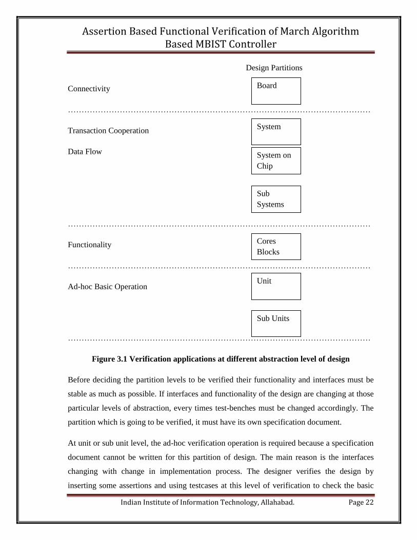
3.2.3 Levels of Verification
The design implementation goes through the various levels like logical partition (synthesis of
units, blocks, reusable cores etc.) and physical partition (PCBs, FPGAs, ASICs etc.) so it is
most necessary to decide the level of verification.Figure9 shows the abstraction levels of
design and their verification requirements/ applications.
Page 23
Assertion Based Functional Verification of March Algorithm Based MBIST Controller
Indian Institute of Information Technology, Allahabad. Page 22
Design Partitions
Connectivity
…………………………………………………………………………………………………
Transaction Cooperation
Data Flow
…………………………………………………………………………………………………
Functionality
…………………………………………………………………………………………………
Ad-hoc Basic Operation
…………………………………………………………………………………………………
Figure 3.1 Verification applications at different abstraction level of design
Before deciding the partition levels to be verified their functionality and interfaces must be
stable as much as possible. If interfaces and functionality of the design are changing at those
particular levels of abstraction, every times test-benches must be changed accordingly. The
partition which is going to be verified, it must have its own specification document.
At unit or sub unit level, the ad-hoc verification operation is required because a specification
document cannot be written for this partition of design. The main reason is the interfaces
changing with change in implementation process. The designer verifies the design by
inserting some assertions and using testcases at this level of verification to check the basic
Board
Unit
Sub Units
Cores
Blocks
System on
Chip
System
Sub
Systems
Page 24
Assertion Based Functional Verification of March Algorithm Based MBIST Controller
Indian Institute of Information Technology, Allahabad. Page 23
functionality. A large and complex design has many design units but it is necessary to
perform the verification at unit level. This increases the controllability and observability of
design during verification which helps to provide confidence to validate the design.
The block level verification is done independently because this partition of design has its
own independent documentation. A block comprised units of the design. All blocks of design
require same effort of verification and it does not depend on the sizes of blocks. The blocks
in a design may have different sizes. Design includes the some reusable core blocks which
have their own intended functionality in different designs. So they must be verified
independently for usage in any design. Here assertions play critical and important role to put
restrictions and requirements for such core blocks of design so that the blocks does
functionality as intended in that particular design.
At block level verification, the features are verified which are within it. Once verified then it
can be assume that verified features will work well at higher level verification. When
features verified at block level have the interaction with other blocks then they have to be
verified again at higher level to ensure the correct integration of blocks.
When system level verification is done then at that time the functionality of block level
design must be perform correctly. At system verification the focus is kept on integration of
different blocks or sub systems.
3.2.4 Tools and Strategies
In this section it is decided what will be the strategies and tools to verify the design.
Selection of tools and strategies depend on the requirement of design module whether it can
be verified using formal techniques or simulation techniques etc. A design or its modules can
be verified with different verification techniques and strategies. More about this can be found
in section 3.1 and chapter 4.
Page 25
Assertion Based Functional Verification of March Algorithm Based MBIST Controller
Indian Institute of Information Technology, Allahabad. Page 24
3.2.5 Specifications to Features of the Design
This step is the heart of verification plan because complete verification plan revolves around
it. It decides what and which type of features will be verified in verification plan. Then it
decides what verification strategy should be followed. The specifications from the
documentation of design are converted in to the features during the implementation. Now
these features are verified against their specifications. Sometime system architects and RTL
designer add some extra features to be verified. It is explained [20] how to extracts the
features to verify and what are the relevant features at interfaces, functions and then the
corner cases.
Most of the interface features can be written to find the answers of the following questions.
What type of transactions can be applied?
a) Transaction’s values?
b) What are the protocol violations in design?
c) Interactions between interfaces?
d) Synchronization of transactions?
3.2.6 Assertions
The Planning of assertions is very important in a verification plan because different
assertions are used to check the more details about the design. When assertions are included
in verification process then an assertion language like system Verilog is used to specify the
expected behavior of a design in form of assertions. Assertions are checked mainly in two
ways one is dynamically and other is statically. When assertions are checked dynamically
then it is simply called assertion based dynamic verification. Here, dynamic term is linked to
the simulation. There are following main uses of assertions.
i) Clarify specification requirements.
ii) Capture design intent of implementation.
iii) Validate correct operation and usage of design.
Page 26
Assertion Based Functional Verification of March Algorithm Based MBIST Controller
Indian Institute of Information Technology, Allahabad. Page 25
There are following two types of assertions.
a) Immediate Assertions
b) Concurrent Assertions
Sometime assertions are also categories based on whether these are implemented by design
engineer or verification engineer [21].
While implementing the assertions it is necessary to define the place where to embed these
assertions. Assertion can be embedded in different places like in test-bench, in the source
code or by using bind statement as a separate file. Besides that, the following information
should also be specified.
a) Functionality which is going to be verified by assertion.
b) Where the assertion is placed whether it is external or internal to design.
c) Type of assertion whether it is immediate or concurrent assertion.
d) Whether assertion is implemented by design engineer or verification engineer.
3.2.7 Coverage Collection, points and Goal
To obtain the coverage results, first types of coverage are defined then cover points in the
design and the goals for the various types of coverage metrics. The coverage points are
defined for the functional coverage metric. So the cover points must be listed after the
planning. The list of cover points should consist following points.
a) Name of signal or expression to cover
b) Motive to cover
c) Placement of coverage groups whether it is internal or external to design.
d) Defined the coverage goal for various coverage metrics/ groups.
Page 27
Assertion Based Functional Verification of March Algorithm Based MBIST Controller
Indian Institute of Information Technology, Allahabad. Page 26
3.3 Coverage
A verification engineer can determines the level or depth of verification by coverage
analysis of the design under verification (DUV). It can be analyzed that which part of HDL
code of design is tested or not during simulation by monitoring the execution of code. The
coverage analysis highlights the uncovered code portion[22] thus It provides the clear
understanding where to put the effort to test untested design functionality to achieve 100%
coverage which is desirable for any design. Achieving 100% coverage cannot give 100%
surety that design is error free. It provides the systematic approach to attain completeness of
verification.
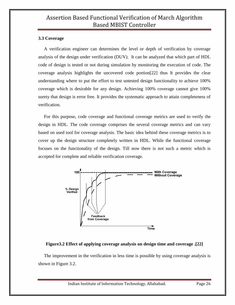
For this purpose, code coverage and functional coverage metrics are used to verify the
design in HDL. The code coverage comprises the several coverage metrics and can vary
based on used tool for coverage analysis. The basic idea behind these coverage metrics is to
cover up the design structure completely written in HDL. While the functional coverage
focuses on the functionality of the design. Till now there is not such a metric which is
accepted for complete and reliable verification coverage.
Figure3.2 Effect of applying coverage analysis on design time and coverage .[22]
The improvement in the verification in less time is possible by using coverage analysis is
shown in Figure 3.2.
Page 28
Assertion Based Functional Verification of March Algorithm Based MBIST Controller
Indian Institute of Information Technology, Allahabad. Page 27
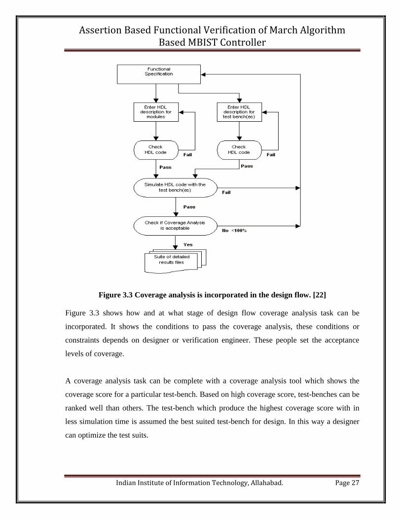
Figure 3.3 Coverage analysis is incorporated in the design flow. [22]
Figure 3.3 shows how and at what stage of design flow coverage analysis task can be
incorporated. It shows the conditions to pass the coverage analysis, these conditions or
constraints depends on designer or verification engineer. These people set the acceptance
levels of coverage.
A coverage analysis task can be complete with a coverage analysis tool which shows the
coverage score for a particular test-bench. Based on high coverage score, test-benches can be
ranked well than others. The test-bench which produce the highest coverage score with in
less simulation time is assumed the best suited test-bench for design. In this way a designer
can optimize the test suits.
Page 29
Assertion Based Functional Verification of March Algorithm Based MBIST Controller
Indian Institute of Information Technology, Allahabad. Page 28
3.3.1 Code Coverage
Code coverage has several types of coverage metrics. Sometime different names are used for
similar types of coverage metrics [23] depending upon the understanding and used coverage
tool. Most of them are explained below.
i) Line Coverage: Line is one of the simplest structures of HDL code. A line of system
Verilog code is said to be covered if it has had transaction on it. An event may or may not
occur during transaction at that line but line count as covered. [24]
ii) Statement Coverage: This coverage metric only counts the executable statements from
HDL implementation of design during coverage analysis. A line may contain more than one
statement.
iii) Block Coverage: Block coverage is also called segment coverage of HDL code. Its
measuring unit of code is a sequence of non-branching codes which is executed at the same
simulation time [23]. Block coverage reduces the recording units for coverage analysis.
Mostly system tool records as block coverage and display results in term of statement
coverage but there is a slightly difference between them.
iv) Branch Coverage: Branch coverage metric is also called decision coverage matric. This
metric involved the control flow through the HDL code during simulation and can be
represented as control flow graph (CFG) to code [26].
v) Path Coverage: Path coverage measures the coverage of all paths present in the HDL
code. A path is defined as a unique sequence of branches or decisions from the starting of a
code section defined in HDL to the end of it [26]. A path in HDL code must contain an edge
which is not included in other paths. Path coverage score is based on to cover multiple
sequential decisions.
Page 30
Assertion Based Functional Verification of March Algorithm Based MBIST Controller
Indian Institute of Information Technology, Allahabad. Page 29
vi) Conditional coverage: Conditional coverage or multiple condition coverage [27] is
sometimes called expression coverage because the conditions are evaluating based on
variable or expression in the conditional statements. It provides the coverage statistic for
variables and expressions. It is a very important and critical coverage metrics because it can
find the errors in the conditional statements that cannot be easily found by any other
coverage analysis [23].
vii) Event Coverage: Most HDL simulators are event-driven. Therefore, it is necessary to
care about the possible events in a design. Events are associated with the change of a signal.
This coverage metrics is very useful when there are too much control events in the design.
viii) FSM Coverage: In code coverage point of view, the FSM coverage metric cover
number of traversed states in FSM design during the simulation. Here FSM coverage is
defined as language-based code coverage for the HDL code just to show whether the all
design states are traversed or not. It is most important coverage metric for the FSM based
design because it found out most of the design bug due to its closeness to the behavior of
design space.
3.3.2 Functional Coverage
Metrics defined in this category such as toggle coverage, Sequence and transition coverage
of FSM and assertion coverage are related to computation performance of HDL code rather
than its structure [26]. The main motive to define such metrics was to exercise each
functional scenario of the design after HDL implementation. In FSM designs while
performing functional coverage, the coverage monitor looks for error in state transitions and
event sequencing mainly. Assertions which interpret design hardware functionality in system
Verilog language are considered the special case to monitor in functional coverage analysis.
There are following metrics which are considered as functional metrics in this work.
i) Toggle Coverage: Sometime toggle coverage is also called as variable coverage [23]. It
measures that each bit in the nets and registers or bits of logic change their polarity during
simulation and not stuck at one level [22]. Toggle coverage metrics is considered as first
Page 31
Assertion Based Functional Verification of March Algorithm Based MBIST Controller
Indian Institute of Information Technology, Allahabad. Page 30
functional coverage metric because without tested a bit properly function coverage target
cannot be complete.
ii) FSM’s Transition and Sequence Coverage: As functional coverage point of view of
FSM design, the transition coverage metric and sequences coverage metric are considered as
functional coverage. The transitions and possible sequences in HDL code among the states of
FSM depend on the functionality of design.
iii) Assertion Coverage: Assertions are embedded within the HDL code of design annotates
the functionality of design and their main purpose was to generate the assertion coverage
metric. This assertion coverage metric covered the successful execution of assertions written
form specification documentation of design [6]. Assertion coverage is generated by defining
cover groups or cover properties. Cover groups include more than one cover point usually
where expected value of data signals are grouped or written in ranges called bins. Every
cover group comprises its bin and coverage analysis shows covered and not covered bins.
Cover properties also another functional coverage technique. A cover property can be
defined for the property defined as an assertion that’s why cover property is more like
assertion. The analysis result for cover properties shows the number of hits, matches and no
matches.
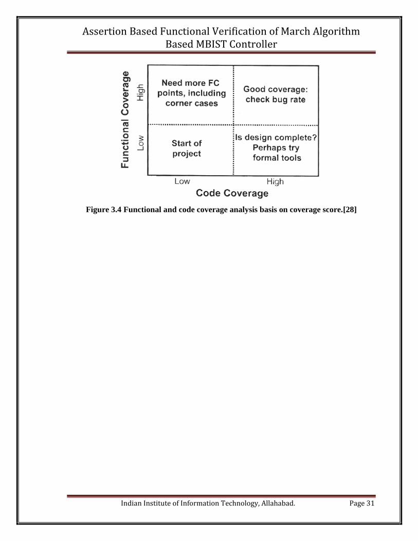
3.3.3 Completeness of Verification
Coverage analysis is the only way to know that how much a design has been verified and
completeness of verification.Figure3.4shows how to proceed to get the desired code or
functional coverage. The goal of verification is always high functional coverage and high
code coverage as much as possible.
Page 32
Assertion Based Functional Verification of March Algorithm Based MBIST Controller
Indian Institute of Information Technology, Allahabad. Page 31
Figure 3.4 Functional and code coverage analysis basis on coverage score.[28]
Page 33
Assertion Based Functional Verification of March Algorithm Based MBIST Controller
Indian Institute of Information Technology, Allahabad. Page 32
Chapter 4
Tools and Languages
The presented thesis work is the design and verification of MBIST controller. The Synopsys-
VCS® is used as the verification tool and System Verilog is used as the Hardware Design
and Verification Language (HDVL).
Initially, there were two main verification languages ‘e’ and ‘Vera’. These languages
introduced the constraint randomization and object orientation features in to the traditional
verification. But disadvantage with any Hardware Design Language (HDL) and using ‘e’ or
‘Vera’ as verification languages is that these are completely different languages and both
must be known. But a lot of work is already done in ‘e’ and ‘Vera’ [29].
Now System Verilog which is main stream language for both hardware design and
verification. System Verilog is a verification language with all important and crucial features
of HDLs. That’s why it is called the HDVL. The System Verilog as a HDVL is described in
next section.
4.1 System Verilog
It is well known that System Verilog language is extension of Verilog HDL. But in real
scenario it is the merger of well know programming languages (C, C++), HDL (verilog) and
verification languages (e, Vera & PSL). System Verilog comprises additional features like
enumerated type, structs types, typedefs, type casting and various operators, operators
overloading, control flow statements . It also includes the features of object oriented
programming constructs like classes, dynamic object creations etc. Features found in
concurrent programming languages (Java) are also added to System Verilog.
System Verilog language is design by integrating the best of all these languages mentioned
above into one language. Now design and verification engineers are able to work with single
language. Due to use of same language throughout design flow, the execution of design,
Page 34
Assertion Based Functional Verification of March Algorithm Based MBIST Controller
Indian Institute of Information Technology, Allahabad. Page 33
assertions, test and coverage can be done using single kernel by EDA tools. Because the use
of same language to write design code, assertions and test-bench, no special APIs are
required to accessing each other [30]. The most important and crucial features added to
system Verilog except HDL features are needed for verification.
There are following reasons behind system Verilog to become the first and main choice of
design engineers.
a) Reduction in number of coding errors due to reduction in the design code.
b) A complex functionality can be represented in concise and easier way to read and
reuse as RTL code representation.
c) Very close representation of HDL code to actual hardware.
d) Mismatch reduction between functionality of RTL representation and gate level
functionality after synthesis.
e) Use of single language throughout design flow. (RTL models, test programs, bus
functional model, reference model)
System Verilog extension to the Verilog for verification specifically includes the following
features.
a) Constraint and biased random variable generation
b) Layered test bench generation
c) User defined coverage points or groups
d) Assertions Based Verification
e) Functional coverage
f) Object Orientated features
g) Application Programming Interfaces (APIs)
In 2005, System Verilog became the IEEE Standard as a HDVL language. The APIs of
system Verilog used to interface the other language models (like System C) with the System
Verilog models. It also helps to process and extracts functional & assertion coverage
information.
Page 35
Assertion Based Functional Verification of March Algorithm Based MBIST Controller
Indian Institute of Information Technology, Allahabad. Page 34
There is a verification methodology proposed by Synopsys is called Verification
Methodology Manual (VMM) and it completely supported by system Verilog [31]. This
thesis work used system Verilog language as for both design and assertion based dynamic
verification.
4.1.1 System Verilog Enhancements to Verilog
System Verilog enhances the Verilog’s capability to represent the hardware designs as
Register Transfer Logic in several ways.
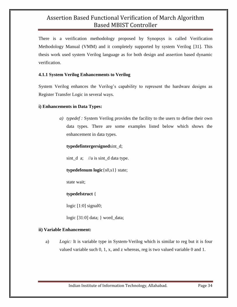
i) Enhancements in Data Types:
a) typedef : System Verilog provides the facility to the users to define their own
data types. There are some examples listed below which shows the
enhancement in data types.
typedefintergersignedsint_d;
sint_d a; //a is sint_d data type.
typedefenum logic{s0,s1} state;
state wait;
typedefstruct {
logic [1:0] signal0;
logic [31:0] data; } word_data;
ii) Variable Enhancement:
a) Logic: It is variable type in System-Verilog which is similar to reg but it is four
valued variable such 0, 1, x, and z whereas, reg is two valued variable 0 and 1.
Page 36
Assertion Based Functional Verification of March Algorithm Based MBIST Controller
Indian Institute of Information Technology, Allahabad. Page 35
iii) For Loop Enhancement:
System Verilog also allows the multiple for-loop control variables which are local variables
to the for-loop. Ex.
for (int a=0, b=a+const; a<=10; a++, b++)
iv) Task and Function Enhancements:
System Verilog improves the task and function features in several ways from the Verilog
HDL.
There are following enhancements in tasks and functions as compare to task and function in
Verilog.
a) Function declaration as void.
b) return can be used to return a function value.
c) Function arguments can be any data type, array, structures, unions and user-
defined type.
d) Formal arguments for input and output.
v) Module and Interface Instances:
In Verilog, the ports connection and instantiation of modules are verbose whereas System
Verilog provides the short cuts of these. There are two types of short cuts one is dot-name
and other is dot-star. In dot-star all ports having same names are connected to each other.
Module A1 (.*, .clk(mclk), .ad () ); //ad is not used.
The ports having different names are connected using dot-name approach.
There are many more enhancements to Verilog can be found in system Verilog
documentations. [31]
Page 37
Assertion Based Functional Verification of March Algorithm Based MBIST Controller
Indian Institute of Information Technology, Allahabad. Page 36
4.2 Synopsys VCS
VCS is used as a high performance compilation, simulation and most important as a
verification tool in parallel to simulation of design. VCS provides all these features on single
open native platform. VCS delivers the fast and high capacity simulation for RTL functional
verification which fasten the overall system verification. VCS’s simulating and debugging
features assures the validation of the design. VCS provides the complete package of
verification which supports the languages other than Verilog and System Verilog. But
System Verilog and VCS both are very much compatible to each other. VCS in its VCS-
MX[31, 32] mode also supports mixed language designs like with VHDL.
VCS is supported by the multicore facility due to this it reduced the verification time
comparatively other verification tools. It runs the design, test-bench, coverage, assertions and
bug finding process in parallel due to multicore technology.
The some main components [31] of VCS are following.
i) System Verilog: VCS supports the System Verilog 3.1a except some features of System
Verilog. Mainly system Verilog adds the new design, assertion and test-bench constructs.
ii) System Verilog Assertions (SVAs):VCS supports and very much compatible with
System Verilog Assertion like with Open Vera Assertions.
System Verilog Assertion performs following tasks.
a) These can test the Verilog, VHDL, System Verilog and mixed HDL design codes
using VCS and VCS-MX.
b) The results produced by the assertions can be viewed with DVE.
c) These can be monitored and controlled as part of design code and System Verilog
test-bench.
SVAs have two following directives.
a) Assert -This assert directive is written to define a property which represents a
functional characteristic of the system. Such properties are specified in form of
Page 38
Assertion Based Functional Verification of March Algorithm Based MBIST Controller
Indian Institute of Information Technology, Allahabad. Page 37
temporal expressions most of the times. These temporal expressions represent the
complex timing and functional behavior of the system.
b) Cover -A cover directive is used to verify that a property or sequence which is
defined in assertions was covered or not. Based on whether a coverage expression
matched or failed to match, the cover directive generates the report of number of
times an asserted property got success or failed during simulation. More than one
matches or failures are possible in single attempt. In case of multiple matches, a
counter is incremented at every match.
iii) Discovery Verification Environment (DVE):DVE is the graphically debugging
environment of VCS. In DVE, one can trace the signals of only which are needed to check.
After looking into wave forms one can find the bug by comparing the waves and debug. The
test-benches can be formed based on the waveforms outputs. The default DVE window is
shown in Figure13. This default format of DVE Top-Level window can be changed.
iv) Coverage Metrics built in VCS: The built in coverage analysis functionality of VCS
comprises nearly all aspects of coverage analysis. This analysis includes condition, toggle,
line, Finite State Machine (FSM), path, branch and assertion coverage. This every coverage
is represented in the form of metric and in these metrics coverage score determines the
quality of design during verification. If the coverage is not satisfactory then focus will be on
creating some new or additional test cases. Just one time compilation is enough to run the
simulation and coverage analysis and to generate results.
Page 39
Assertion Based Functional Verification of March Algorithm Based MBIST Controller
Indian Institute of Information Technology, Allahabad. Page 38
Hierarchy Browser Data PanSource Window
Menu Bar Tool Bar
Console Bar Tcl command in line interface Console Targeted Window Control
Figure 4.1 Synopsys VCS® GUI Window frame.
v) Direct C/C++ Interface : If C/C++ like functions are used with in Verilog HDL design
code , then such required interfaces are directly provided by system Verilog. There is no
Page 40
Assertion Based Functional Verification of March Algorithm Based MBIST Controller
Indian Institute of Information Technology, Allahabad. Page 39
need to write separate Programming Language Interfaces (PLI) to interface such functions or
modules. VCS has the capability to recognize such functions automatically and to compile &
simulate them.
vi)Incremental Compilation: In VCS once a design has been compiled then in the next
compilation VCS compiles only the part of design code which is modified only. For the rest
design it gets the data from the previous compilation data. This is the incremental
compilation. The csrc subdirectory stores the compilation time files and results.
vii) Mixed Signal Compilation: It is very challenging to verify digital and analog modules
together because it required such verification architecture which supports both digital and
analog designs simultaneously. Here VCS AMS test-bench provides the solutions to this
problem. The traditional digital verification techniques are used with some modification so
that it can drive analog IPs like ADC/DAC, clock generator etc.
The more details about mixed signal simulation with VCS can be found in Discovery AMS
documentation.
Page 41
Assertion Based Functional Verification of March Algorithm Based MBIST Controller
Indian Institute of Information Technology, Allahabad. Page 40
Chapter 5
Implementation of MBIST Controller
The controller generates the control signals for other components of MBIST circuitry such as
patt_g for data/pattern generator, en to start the address counter inside the address generator,
rw for Read/ writes generator and en for signature analyzer and other components too. The
top level block diagram of MBIST is shown in Figure 5.1. Mainly the controller handles the
test sequence and its result corresponding to memory output. After assertion of T_mode
signal from higher level processor or controller, MBIST controller generates the control
signals corresponding to the pattern generator, address generator, read/write and signature
analyzer. Controller and pattern generator control the up or down address sequence by
generating the control signals for address generator. The generation of March pattern is
based on the ‘0’ or ‘1’ value of control signal patt_g whether it is marching 0 or 1. Controller
generates the control signal rw to the read/write controller for the reading or writing
operations from and into the memory [9, 10].
Figure5.1 MBIST architecture with FSM controller.
Match signal is the output of signature analyzer and input to the controller. Based on the
value of match, controller asserts the pass or fails if match is ‘1’ or ‘0’ correspondingly. Only
Page 42
Assertion Based Functional Verification of March Algorithm Based MBIST Controller
Indian Institute of Information Technology, Allahabad. Page 41
after completion of March test sequence, controller asserts the done signal. The controller is
designed based on March C algorithm [10, 14] which is capable to detect SAFs, AFs, TFs
and CFs (except linked CFs) with an additional pause element to detect the data retention
faults (DRFs) in memory.
5.1 Implementation of March Algorithm
The March C algorithm consists six march elements say M1, M2, M3, M4, M5 and M6. The
pause element M7 is added to test the retention time of SRAM under test. It does not access
the memory while it pauses the marching of element to check whether memory is able to
retention the written data or not for a particular time. Pause element is added just after the
write element to check which memory cell is not capable to retain the same written data after
a particular time. During pause the controller does not allows the execution of the original
march test sequence of read/write operations on memory under test.
{ (w0); (r0, w1); (r1, w0); (r0, w1); (r1, w0); (r0); (pause)}
M1 M2 M3 M4 M5 M6 M7
Figure 5.2 March C algorithm with pause element.
Here five read March elements are encountered and each encounter is capable of
detecting faults in memory. The controller’s implementation is based on March algorithm
shown in Figure 5.2 which is capable to detect SAFs, AFs, TFs, CFs (except linked CFs) and
data retention faults (DRFs). The March C algorithm includes 6 march elements say M1,
M2, M3, M4, M5 and M6. But here in Figure5.2, the implemented algorithm comprises an
additional element pause say M7 to check the memory data retention time through this
detection and identification of data retention faults are possible.
5.1.1 Various Fault Detection by Read Operations in March Elements
By assigning F1, F2, F3, F4, F5 and F6 syndromes [10] to the all five read and pause
element operation correspondingly to distinguish whether an operation detects a particular
Page 43
Assertion Based Functional Verification of March Algorithm Based MBIST Controller
Indian Institute of Information Technology, Allahabad. Page 42
type of fault or not. The 1 value of any syndrome shows that the corresponding operation is
able to detect that particular fault and 0 value shows that fault could not be detected by this
operation. The value of syndromes with different memory faults is shown in Table 5.1.
It is clear that all read operations are able to detect the address faults because all syndrome
value is 1 for AF. The March element in March C algorithm having a read operation also
consists an opposite write element except M6. Due to the presence of defect, [11] more than
one address is selected and the different logic values are read at the same time on the bit-line.
And the bit-line gets the undefined logic value(x). All syndromes value are also 1 for
coupling faults except F6, it means all five read operations are able to detect coupling faults.
But all syndromes values are 1 for data retention faults (DRFs) it means all read and pause
operation can detect the retention faults in memory but the only 1 value of F6 syndrome can
assure the detection of DRFs.
Table 5.1 Fault detection Syndromes corresponding to all five read and pause element
in March algorithm.
Faults
Syndromes
F1 F2 F3 F4 F5 F6
SAF(0) 0 1 0 1 0 0
SAF(1) 1 0 1 0 1 0
TF < 0> 0 1 0 1 0 0
TF < 1> 1 0 1 0 1 0
AF 1 1 1 1 1 0
CF 1 1 1 1 1 0
DRF 1 1 1 1 1 1
5.2 FSM Implementation of MBIST Controller
The Figure 5.3 shows the implemented FSM structure of MBIST controller which is easy
to implement as a FSM and very feasible if no further improvement is required in MBIST
Page 44
Assertion Based Functional Verification of March Algorithm Based MBIST Controller
Indian Institute of Information Technology, Allahabad. Page 43
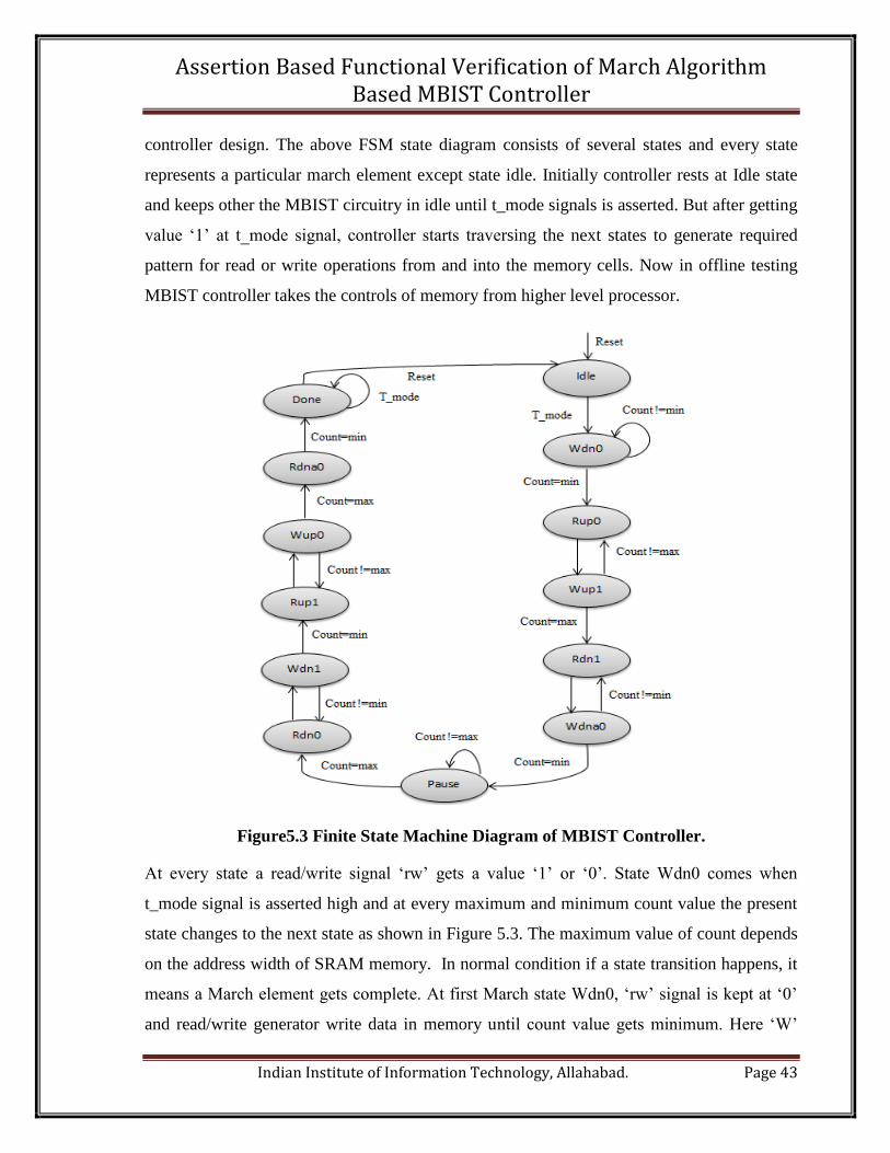
controller design. The above FSM state diagram consists of several states and every state
represents a particular march element except state idle. Initially controller rests at Idle state
and keeps other the MBIST circuitry in idle until t_mode signals is asserted. But after getting
value ‘1’ at t_mode signal, controller starts traversing the next states to generate required
pattern for read or write operations from and into the memory cells. Now in offline testing
MBIST controller takes the controls of memory from higher level processor.
Figure5.3 Finite State Machine Diagram of MBIST Controller.
At every state a read/write signal ‘rw’ gets a value ‘1’ or ‘0’. State Wdn0 comes when
t_mode signal is asserted high and at every maximum and minimum count value the present
state changes to the next state as shown in Figure 5.3. The maximum value of count depends
on the address width of SRAM memory. In normal condition if a state transition happens, it
means a March element gets complete. At first March state Wdn0, ‘rw’ signal is kept at ‘0’
and read/write generator write data in memory until count value gets minimum. Here ‘W’
Page 45
Assertion Based Functional Verification of March Algorithm Based MBIST Controller
Indian Institute of Information Technology, Allahabad. Page 44
represents the write operation, ‘dn’ shows the down marching and ‘0’ shows that marching
pattern is 0. During up marching, count starts from minimum address value to the maximum
address value and state changes only when count gets its maximum value unless t_mode and
reset signal change. In case of down marching, state transition occurs only when count gets
its minimum value. Pause state is inserted between a write state (Wdn0) and a read state
(Rdn0). During pause, controller just holds the marching operation on memory for the
specified time. The March testing follows the read-test-write sequence that’s why every read
state in FSM design comprises the test result as a signal pass /fail. After completion of test
controller enters into the Done state and controller asserts the done signal to show that the
test is completed. The FSM shown in Figure5.3 is implemented using System Verilog in
Synopsys VCS tool.
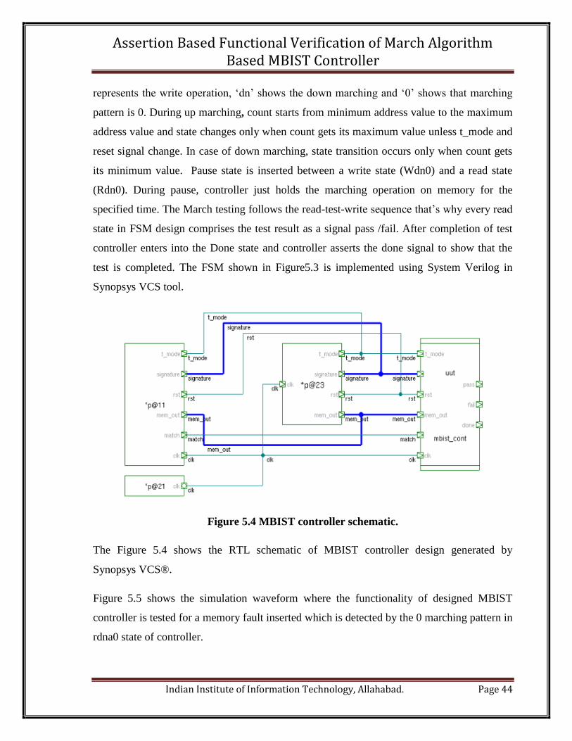
Figure 5.4 MBIST controller schematic.
The Figure 5.4 shows the RTL schematic of MBIST controller design generated by
Synopsys VCS®.
Figure 5.5 shows the simulation waveform where the functionality of designed MBIST
controller is tested for a memory fault inserted which is detected by the 0 marching pattern in
rdna0 state of controller.
Page 46
Assertion Based Functional Verification of March Algorithm Based MBIST Controller
Indian Institute of Information Technology, Allahabad. Page 45
Figure 5.5 Simulation output of MBIST controller.
If match signal value is high then it shows that the output pattern matches with signature. It
means there is no defect in memory. Now if match becomes low at any time it shows the
detection of fault in memory. After this, with in one clock pulse, the fail signal will be
asserted and simultaneously the pass signal will be deasserted.
Page 47
Assertion Based Functional Verification of March Algorithm Based MBIST Controller
Indian Institute of Information Technology, Allahabad. Page 46
Chapter 6
Functional Verification of MBIST controller
The functional verification of RTL model of MBIST controller is done using two different
approaches one is the traditional way to verify the RTL model and another is assertion based
dynamic verification.
The traditional functional verification used some test cases and based on those test cases the
functionality of design is verified. But to know whether design has performed correct
functionality or not, it has to look or watch signal to signal in the wave window generated by
HDL simulator.
The simulation waveforms and coverage reports of traditional verification and assertion
based dynamic verification is shown in chapter 8.
6.1 Assertion Based Dynamic Verification with Verification Plan
System Verilog Assertions (SVA), as a set of System Verilog language are embedded [15]
into the design code of MBIST controller enabling the simulator to check the assertions
during the dynamic verification of MBIST controller. A cross checks between intended and
actual design of MBIST controller is provided by assertions. Assertions have been written
from the specification/properties of the design, from design document and from the
understanding of the FSM design of MBST controller. Increased number of successful
assertions increases the functional coverage of design which ensures that the design’s
functionality has been verified exhaustively not only at top level but also internally.
Now the verification plan for MBIST controller follows the following steps.
6.1.1 General Information about MBIST Controller as DUV
MBIST controller based on modified March C algorithm is implemented for design under
verification. It controls the MBIST testing operation on SRAM. Controller is design by
keeping in mind to test 32 bit single port SRAM under test. The controller design comprises
the total 13 states where chosen March algorithm has 11 states and two extra states for
Page 48
Assertion Based Functional Verification of March Algorithm Based MBIST Controller
Indian Institute of Information Technology, Allahabad. Page 47
controller idle and done state. There are some primary inputs and outputs of controller. The
detail information of MBIST controller is presented in implementation of MBIST controller.
6.1.2 MBIST Controller Interface’s Verification Requirements at Block Level
MBIST controller is considered as a block box [3] shown in Figure6.1. Here, only the
interfacing signals between controller and other MBIST circuitry such as pattern generator,
read/write generator, address generator and signature analyser are considered. Interface
signals are verified for the timing requirement mainly by writing the assertions and by
checking whether the test cases are invoking the interface signals or not.
Figure 6.1 MBIST controller as black box.
6.1.3 MBIST Controller Internal Operations and Functional Spots
MBIST controller is the very crucial part of MBIST architecture. It requires great effort to
verify its functionality because if something goes wrong with controller, it affects MBIST
adversely. Here controller is implemented as a FSM, now checking whether the FSM works
exactly the same way as intended in design specification is the way to verify the controller.
The FSM’s transitions and decisions are main internal functional spot to verify [12] in FSM
of MBIST controller. Transitions and Timing requirements are verified using System
Verilog assertions.
FSM/Hardwired
MBIST_Controller
T_mode
Clock
Reset
Match
Done
Pass
Fail
Page 49
Assertion Based Functional Verification of March Algorithm Based MBIST Controller
Indian Institute of Information Technology, Allahabad. Page 48
6.1.4 Assertions
Here, plain language requirements of MBIST controller are converted into formal properties
using System Verilog Assertions. It would be mandatory to check the desirable requirements
for the design by using assertions in real verification projects. A function with more than
two logic events is verified using a SVA keyword ‘sequence’. A simple logic change is an
event, can also be change in expression or Boolean sub expression. A SVA key word
‘property’ is used to verify the complex function of controller and it also includes the
sequences for some complex functions [2]. These defined properties are verified during
dynamic verification and checked by using a key word ‘assert’.
6.1.5 Code Coverage Goal
Before code coverage analysis and to know the completeness of verification, the code
coverage goal has to be set. Code coverage involves different types of coverage metrics
which their own coverage goals. Here, line coverage, statement coverage, block coverage,
branch coverage, path coverage, conditional coverage, event coverage and FSM coverage are
planned to analyze against their planned coverage goal. The coverage goals are set to be
100% as shown in Table 6.1. If any design portion or code is not covered then it is
explained.
Table 6.1 Code Coverage Goal
Code Coverage Coverage Goal
Line Coverage 100% explained
Statement Coverage 100% explained
Block Coverage 100% explained
Branch Coverage 100% explained
Path Coverage 100% explained
Conditional Coverage 100% explained
Event Coverage 100% explained
FSM Coverage 100% explained
Page 50
Assertion Based Functional Verification of March Algorithm Based MBIST Controller
Indian Institute of Information Technology, Allahabad. Page 49
6.1.6 Functional Coverage Goal
The functional coverage for all assertion, toggle and FSM transitions & sequencing are
planned. The assertions are categorized based on two functional levels one at interface and
other inside the MBIST controller. Firstly the assertions are written to check the all interface
requirements. Others will be checking the internal functionality requirements of MBIST
controller. The functional coverage is planned by using the cover property for all assertions.
The functional coverage goal for all of them is planned 100 % as shown in Table 6.2.
Table 6.2 Functional Coverage Goal
Functional Coverage Coverage Goal
All Cover Properties 100 %
Toggle 100 %
FSM Transitions 100 %
FSM Sequencing 100 %
6.2 Implementation of Verification Plan
Implementation of Verification Plan for MBIST controller’s assertion based verification is
presented in this section. It comprises two main subsections.
6.2.1 Four Steps towards Assertion Based Verification of MBIST Controller
Assertion Based Verification addresses all the challenges faced during only simulation based
validation of design without the use of assertions. Here, assertions are defined for MBIST
controller with complete assertion’s ontology [11] which includes the information about
assertion under construction such as class, type, name, expression, message, severity level,
condition and snippet. The SVAs are written for MBIST controller to check the required
specifications and functional properties according to verification plan. Based on the
verification requirements, assertions for MBIST controller design are categorized only on the
basis of class and other ontological information would be covered with this.
Page 51
Assertion Based Functional Verification of March Algorithm Based MBIST Controller
Indian Institute of Information Technology, Allahabad. Page 50
A four step approach is used for assertions based functional verification of MBIST
controller.
i) At Interface Boundary of MBIST Controller: It is a block level based approach to write
the assertions for MBIST controller. It is mentioned in section 2 that MBIST controller
interacts with several blocks in MBIST architecture and other than MBIST too. SVAs are
written here to check whether the controller interface/boundary signals are according to the
required controller’s specification or not. Here, assertions mainly check the timing
requirements among the interface signals [12]. The timing requirements for interface signals
to function correctly is shown in Table 6.3. And to check these interface requirements the
SVAs examples are shown in Figure 5.4.
Table 6.3 Verification requirements for the interface signals.
Interface
Signals
Interface Signals their features
Signals Expected Features
1. Reset, T_mode T_mode=1 and reset=0 and its opposite must be synchronous
2. T_mode, en en=1 with in 1clock cycle after t_mode is asserted
3. Match, Pass Pass=1 with in 1clock cycle after match is asserted
4. Match, Fail Fail=0 with in 1clock cycle after match=0
ii) Internal Functional Spots of MBIST Controller: MBIST controller is the control block
of MBIST which is implemented as a FSM. The main verification requirements of FSM are
defined as the transitions among the states, sequencing and timing requirements. For the
every March operation shown in Figure 5.2, there is a different state in controller’s FSM
design. Some of the state transitions are shown in Table 6.4.
Now here, assertions are written according to verification plan and classified to verify the
legal state transitions, correct sequencing, timing requirements and functionality in each
state.
Page 52
Assertion Based Functional Verification of March Algorithm Based MBIST Controller
Indian Institute of Information Technology, Allahabad. Page 51
Table 6.4State transitions those need to be verified.
State
Transiti
ons
Next States
S_idle Wdn0 Rup0 Wup1 Rdn1 Wdna0 Pause Rdn0 Wdn1 Rup1 Wup0 Rdna0 S_done
0 (S_idle)
1 (Wdn0)
2 (Rup0)
3 (Wup1)
4 (Rdn1)
5 (Wdna0)
6 (Pause)
7 (Rdn0)
8 (Wdn1)
9 (Rup1)
10 (Wup0)
11(Rdna0)
12(S_done)
Each check mark in Table 6.4 shows that the state transitions between those state and next
state must be verified. R, W, up, dn stands for read operation on to MUT, write operation,
upward marching means from min address to the max address of MUT and the down
marching means max address to min address, respectively. The SVAs written for all required
transitions to check whether the transitions are happening in correct manner or applied test
cases are exercising all required transitions or not. Two SVAs examples are shown in Figure
6.4. All used assertions are tabled with their explanation in Appendix-A.
Page 53
Assertion Based Functional Verification of March Algorithm Based MBIST Controller
Indian Institute of Information Technology, Allahabad. Page 52
Table 6.5Functional behavior of MBIST controller in different states need to be
verified.
State’s
Transit
ions
States and their internal features
States Expected features
1. S_idle Control signal en=0 to other MBISTcircuitry, Done=0;
2. Wdno Initially counter must consists count value (count=c_max), lastly
count=c_min, The read/write control signal rw=0 and pattern
generate control signal g_patt=0; en=1; Done=0;
3. Rup0 Initially count value (Count =c_min), lastly count=c_max, rw=1,
g_patt= must hold the previous state value, en=1; Done=0;
4. Wup1 Initially count=c_min, lastly count=c_max, rw=0, g_patt=1;
en=1; Done=0;
5. Rdn1 Initially count=c_max, lastly count=c_min, rw=1,
g_patt=previous state value, en=1; Done=0;
6. Wdn0a Initially count=c_max, lastly count=c_min, rw=0, g_patt=0,
en =1; Done=0;
7. Pause Initially count=c_min, lastly count=c_max, all other control
signal will same as in previous state. It holds the further operation
for a particular interval of time, Done=0;
8. Rdn0 Initially count=c_max, lastly count=c_min, rw=1,
g_patt=previous state value, en=1; Done=0;
9. Wdn1 Initially count=c_max, lastly count= c_min, rw=0, g_patt=1,en=1;
Done=0;
10.
Rup1
Initially count=c_min, lastly count=c_max, rw=1,
g_patt=previous state value, en=1; Done=0;
11. Wup0 Initially count=c_min, lastly count=c_max, rw=0, g_patt=0,en=1;
12. Rdn0a Initially count=c_max, lastly count=c_min, rw=1,
g_patt=previous state value, en=1, Done=0;
13. S_done count=c_min, Done=1; no further march test.
Page 54
Assertion Based Functional Verification of March Algorithm Based MBIST Controller
Indian Institute of Information Technology, Allahabad. Page 53
Table 6.5 shows the functionality of MBIST controller in each state which needs to be
verified. In every state, controller asserts or does not assert the some control signal which
controls the other MBIST circuitry according to the testing algorithm shown in Figure 5.2.
Figure 6.4 shows the SVAs examples which are embedded into MBIST controller’s HDL
code to verify the features defined in the Table 6.5. The Fig 6.5 represents their result of
success.
iii) Formalized the properties with SVA: Here we converted plain language requirements
into formal properties using System Verilog Assertions. A function with more than two logic
events is verified using a SVA keyword ‘sequence’. A simple logic change is an event, can
also be change in expression or Boolean sub expression. A SVA key word ‘property’ is used
to verify the complex function of controller and it also includes the sequences for some
complex functions [2]. These defined properties are verified during dynamic verification and
checked by using a key word ‘assert’. Figure 6.3shows some complete system Verilog
assertions and cover properties for functional requirement at interface boundary of MBIST
controller.
Figure 6.2 Assertions for interface features.
Page 55
Assertion Based Functional Verification of March Algorithm Based MBIST Controller
Indian Institute of Information Technology, Allahabad. Page 54
Figure 6.3 Result of SVAs from Figure6.2 during simulation.
The upside arrows for asserted properties Ap5 & Ap8 show the success of assertion and for
cover properties Cp5 & Cp8 shows that the functionality defined in assertion is exercised by
the test cases. And no need to add more test cases to check that particular functionality of
design. The success of Ap5 shown in Figure 6.3 indicate that the control signal en to the
address generator and analyzer gets high value within 1 clock cycle after getting high value
at t_mode pin of MBIST controller.
Figure 6.4 SVAs for state transitions verification.
Page 56
Assertion Based Functional Verification of March Algorithm Based MBIST Controller
Indian Institute of Information Technology, Allahabad. Page 55
Figure 6.5Result of SVAs from Figure 6.4 during simulation.
The results of SVAs checkers written in Figure 6.4 are shown in Figure 6.5. These SVAs are
used to verify the transition from state wdn0 to state rup0 succeeded as Ap13 & Cp13 and to
verify the transition between state rup0 and state s_idle got fail and cover property gave the
mismatch results. The failures of SVA checker rup0_idle indicate that there is still untested
area in design or there is a loop hole between the intended and designed FSM of MBIST
controller. But at the same time the property coverage is also not true. At first, the test cases
are improved to exercise that particular transition.
Page 57
Assertion Based Functional Verification of March Algorithm Based MBIST Controller
Indian Institute of Information Technology, Allahabad. Page 56
Figure 6.6 Examples of system verilog assertions for MBIST controller.
In Figure 6.6, there are two MBIST controller properties are defined as System Verilog
Assertions because it includes the both assertions and functional coverage. First property
f_wdn0 consists two sequences s1 and s2. This property checks the signal g_patt and rw
signal values during the state wdn0. Signal g_patt is the input to pattern generator and signal
rw is the input to the read/write generator. In Figure 6.6, the property rdna0_done is written
in the form of SVA to verify the legal transition from state rdna0 to state done.
iv)Functional coverage: Here we defined functional coverage for all the formalized
properties of MBIST controller in above step. Mainly assertions have two functions one as
checker and another is as functional coverage [15]. It is illustrated in Figure 6.6, that
functional spot is also defined as coverage spot. Figure 6.7 shows run time log file obtain
from verification tool VCS which contains detailed assertion message. Now the errors in the
Page 58
Assertion Based Functional Verification of March Algorithm Based MBIST Controller
Indian Institute of Information Technology, Allahabad. Page 57
design are found and debugged easily. Level of severity has been defined based on the effect
of property failure in MBIST controller design. By default severity level of an assertion is ‘0’
and severity of assertion is defines as ‘error’ at the failure of assertion in Synopsys VCS
verification tool. System Verilog has four severity levels $error, $warning, $info and $fatal
[6]. Severity level of $fatal is so much that it terminates the simulation immediately at failure
of assertion.
Figure 6.7 Portions of run time log file for assertion Ap6.
By examine the run time log file shown in Figure 6.7, it can be easily found out which
assertion failed and at what location.
A run time log file consists the complete information about every assertion. Here in Figure
6.7, it is very clearly the location (at line 157) of assertion Ap6 and name of module
(nc_mbistcontroller.sv) in which Ap6 had been embedded. Assertion Ap6 failed at time 6442
and with property which could not hold at this time. The severity attached with this assertion
is ‘warning’ with a message which is optional to include with the failure of assertion. After
this time the property succeeded.
Page 59
Assertion Based Functional Verification of March Algorithm Based MBIST Controller
Indian Institute of Information Technology, Allahabad. Page 58
Chapter 7
Simulation Setup
This chapter describes the simulation setup [30] of EDA tool Synopsys-VCS® during
MBIST controller RTL implementation and its assertion based functional verification.
7.1 Synopsys-VCS® Setup for Complete Simulation
VCS software’s setup is done for the compilation, simulation and debugging of the test-
bench. The software is only capable to run only on the Red Hat Linux running system. The
software is installed at Linux running server. The communication with the server to access
the license file is done through a SSH client.
7.1.1 Test-bench Compilation
For the test-bench compilation, the vcs command is used and suitable switches are added for
required operations with this. The following command is used to compile the test-bench.
Vcs –Mupdate –lca –sverilog –cm
line+cond+path+branch+tgl+fsm+assert –cm_noconst –
cm_linecontassign –cm_condallops+anywidth+event –cm_fsmopt
sequence –PP –debug_all *.sv –l compile.log
The compile time switches and their description is listed in Table 7.1.
Page 60
Assertion Based Functional Verification of March Algorithm Based MBIST Controller
Indian Institute of Information Technology, Allahabad. Page 59
Table 7.1 Switches in compilation command and their description.
Switch Name Switch Description
-Mupdate To compile only modified module from last compilation
-lca Limited Customer Availability to use extra added features
-sverilog To compile system Verilog source files
-cm To specify type of coverage
-cm assert Compile for System Verilog assertions
-cm_noconst Ignore constant expression and unreachable statements
-cm_linecontassign To monitor continuous assignment
-
cm_condallops+anywidth+event
Monitor non-logical operators of any width and always
block sensitivity expressions for conditional coverage
-cm_fsmopt sequence To cover the sequences in FSMs
-PP Enables the debuging
-debug Compile for debug in DVE
-debug_all Compile for debug in DVE with linestepping features to
debug the design
-l compile.log To save compiler message in log file during compilation
The + sign in cm switch enables the all listed coverage simultaneously. During compilation
some object files are generated which are linked to a executable file simv (by default)in
working directory. This file name can be changed by using a switch. This executable file
simv is used by tool for simulation.
7.1.2 Simulation
The executable files generated during compilation are used to start simulation. During
simulation, switches are also used to do required operations. The following simv command is
used to simulation.
Page 61
Assertion Based Functional Verification of March Algorithm Based MBIST Controller
Indian Institute of Information Technology, Allahabad. Page 60
simv –cm line+cond+path+branch+tgl+fsm+assert –l run.log–
assert -gui
The Table 7.2 contains the switches used in simulation command with their descriptions.
Table 7.2 Simulation time switches and their description
Switch Name Switch Description
-cm line+…+assert For Code coverage collection
-assert To enable assertion setting
-l run.log To Save simulation time log file
-gui To enable the visual debugging interface- DVE
7.1.3 Debugging
To ensure the correct functionality of MBIST controller design, the complete code was tested
and debugged. For simulation and debugging purpose, Synopsys’s VCS-DVE is used. DVE
provide the graphical user interface by showing signal waveforms for debugging. Where,
DVE stands for Discovery Visualization Environment. The detail description of Synopsys’s
VCS is described in section 4.2.
7.1.4 Code, Functional, Assertion and Property Coverage Reporting
The Universal Report Generator (URG) tool is used to generate the functional and assertion
coverage reports. The cmView tool is used to generate the code coverage reports.
The following command is used for code coverage report generation.
vcs –cm_pp –cm_report summary
After that the code coverage report is saved in simv.cm directory in working directory. This
generates the combine coverage report for all code coverage metrics as well as separate
coverage metrics. During code coverage generation the assertion coverage report is
generated separately in the same simv.cm directory.
Page 62
Assertion Based Functional Verification of March Algorithm Based MBIST Controller
Indian Institute of Information Technology, Allahabad. Page 61
The following command is used for the functional coverage report generation.
urg –dirsimv.vdb –format text
The generated report can be found in simv.vdb directory [30]. By default the generated
report are saved in HTML format but the switch –format text is used to save the reports
in text format in the same simv.vdb directory. The assertion property coverage report is
saved during functional coverage generation while assertion coverage report is generated and
saved during code coverage. The VCS tool generates the assertion report containing the
number of attempts, success, failures and incompleteness during the simulation. While to
monitor the sequences and other behavioral aspects of design, property coverage is generated
by the tool. For this a cover property statement is used. In assertion property coverage
reports, simulator saved the number of time a property holds or fails.
The complete simulation and coverage reports are shown in chapter 8.cmview is used to get
the code coverage in both batch and gui mode. In batch mode, cmview saves the report in
text format whereas in gui it shows graphically or pictorially. The different results and
reports are analyzed in chapter 8.
Page 63
Assertion Based Functional Verification of March Algorithm Based MBIST Controller
Indian Institute of Information Technology, Allahabad. Page 62
Chapter 8
Results and Analysis of Coverage Results
This chapter will discuss the MBIST controller’s design implementation and coverage results
achieved during the simulations. Coverage results will comprises the code coverage,
functional coverage and their various types of coverage metrics. Here, the analysis of code
coverage metrics and functional coverage metrics are discussed in details for MBIST
controller design.
8.1 MBIST Controller Simulation Waveform Description
The simulation output in Figure 8.1 shows input and output waveforms of MBIST controller.
The ‘1’ value of pass or fail signal indicates the success and failure of corresponding applied
data pattern on the memory. When the match signal gets ‘0’ value in the next clock cycle,
MBIST controller assert the fail high and low to the pass signal. Again when match goes
high the controller assert pass signal high and low to fail. Whenever rst (reset) signal goes
high, the state immediately switches to the idle state. After attaining idle state, there is no
transition in the state of controller and state gets stable until rst gets low value again.
Controller starts transitions state to next state only when rst is low and t_mode signal gets
high value.
Simulation output shown in Figure 8.1 is only based on some test cases and provides the
functionality check but not completely. With such functional checking, there is a possibility
to leave some corner cases untested. And there is possibility of bugs in such untested corner
cases. These corner cases are tested by using system Verilog assertion for design’s functional
properties and design specification as shown in Figure 8.2. The functional coverage score
without assertion and using all possible test cases is shown in Figure 8.3.After that only
those test cases are used which have the maximum possibility to provide 100 % assertion
coverage because the now functional verification of MBIST controller is depend on assertion
checking.
Page 64
Assertion Based Functional Verification of March Algorithm Based MBIST Controller
Indian Institute of Information Technology, Allahabad. Page 63
Figure 8.1Simulation waveform of MBIST controller design without assertions.
Figure 8.2 Simulation waveform of MBIST controller with assertions.
Page 65
Assertion Based Functional Verification of March Algorithm Based MBIST Controller
Indian Institute of Information Technology, Allahabad. Page 64
The assertion Ap6 is defined to check whether the state is stabilized in next clock cycle or
not when rst signal gets a value ‘1. In Figure 8.2, the assertion Ap6 gets failed at time 22838
and 22864. These are times of positive edges of clock cycles just after clocks at which state
transitions took place to the idle state. In the first clock cycle, state gets change to the idle
state and waits there for the next clock to check whether the state gets stabilized or not.
That’s why at time instances 22838 and 22864 assertion gets failed after that it succeeded.
The row of Cp6 in Figure 6.7 has all up arrows means during the complete verifying time of
asserted property, property gets covered.
The property Cp30 is that state will be remains in the state rdna0 until the address counter
value is not equal to minimum value but in the mid of that rst gets a toggle from low to high.
Due to that state change to state idle and the property written for state rdna0 gets mismatch at
next clock because at this time no rdna0 state exits.
8.2 Verification Results
Verification results for the MBIST controller include the all code coverage metrics scores
and functional coverage score.
8.2.1 Functional Coverage Results
Functional coverage results for MBIST controller verification include the total achieved
functional coverage score, assertion coverage score, detailed assertions report and detailed
cover property report.
The total functional coverage score without assertions is shown in Figure 8.3 and with
assertions coverage score is shown in Figure 8.4. Detailed assertion and cover property
reports are listed in the appendix-B.
Page 66
Assertion Based Functional Verification of March Algorithm Based MBIST Controller
Indian Institute of Information Technology, Allahabad. Page 65
Figure8.3 Total functional coverage score without assertions.
Figure 8.4 Total function coverage score with assertions.
According to verification plan for MBIST controller design all required internal
andinterfacial functional features are exercised using SVAs which helped to apply the
efficient or directed test cases to the controller. Table 10 shows the directed test cases
towards the desired functionality check with total functional coverage of MBIST controller.
37 out of 53 assertion got success with only 6 directed test cases. Based on the failed
assertions, the design bugs are removed and the test cases are improved to get the 100
percent success of the assertions. After applying 25 directed test cases 100 percent assertion
coverage is obtained, as shown in Figure 8.4 and 96.50 percent functional coverage as shown
Page 67
Assertion Based Functional Verification of March Algorithm Based MBIST Controller
Indian Institute of Information Technology, Allahabad. Page 66
in Table 8.1. The main advantage using directed cased in ABV of MBIST controller is that it
reduces the number of test cases from 88 to 25 with only .46 % decrement in total functional
coverage score but with 100 % assertion coverage.
Table 8.1Functional coverage score with different number of test cases and different
number of assertions.
No. of Directed
Testcases
No. of SVAs in
Verification Plan
No. of successful
assertions
Total Functional
Coverage Score
6 53 37 77.86 %
25 53 53 96.50 %
8.2.2 Code Coverage Results
The Figure 8.5 shows the combined report for the various code coverage metrics discussed in
the section 3.4.1. In Table 8.2, the targeted and achieved coverage scores are presented for
various coverage metrics.
Page 68
Assertion Based Functional Verification of March Algorithm Based MBIST Controller
Indian Institute of Information Technology, Allahabad. Page 67
Figure8.5Coverage score for various code coverage metrics.
Table 8.2 Code coverage metric’s and functional coverage metric’s achieved score
against targeted scores.
Coverage Metrics Targeted Goals (%) Achieved Scores (%)
Line 100 99.80
Conditional 100 100
Toggle 100 90.75
Path 100 81.25
Branch 100 94.74
State 100 100
State Transition 100 100
Sequencing 100 99.88
Assert 100 100
Page 69
Assertion Based Functional Verification of March Algorithm Based MBIST Controller
Indian Institute of Information Technology, Allahabad. Page 68
The all achieved scores are analyzed and explain in the next section 8.3
All the results design and verification of MBIST controller are generated using Synopsys-
VCS®.
8.3 Coverage Analysis of MBIST Controller Model
Coverage analysis makes functional verification easy and less time consuming and it also
helps to know whether functional verification is done enough or not. Thats why coverage
analysis plays important role to check the verification completeness of MBIST controller.
The controller’s coverage analysis depends on two main coverages, one is code coverage and
another is functional coverage. Code coverage is independent of functional coverage but it
helps to obtain verification completeness of MBIST controller.
8.3.1 Code Coverage Analysis of MBIST Controller
Here eight different very useful coverage metrics are introduced that can be classified as
code coverage metrics for MBIST controller. Code coverage metrics helped to identify
which structure in HDL code of controller is exercised during simulation.
i) Line Coverage: Line coverage metric as Figure8.6 shows the result of exercised lines
with respect to the total number of lines present in HDL code of MBIST controller.
Figure 8.6 Line coverage score for MBIST controller.
In Figure 8.6, the total line coverage score is around 98.5% for system verilog HDL code
of MBIST controller . At the same time the Figure 8.7 shows the covered lines and
Page 70
Assertion Based Functional Verification of March Algorithm Based MBIST Controller
Indian Institute of Information Technology, Allahabad. Page 69
uncovered line in HDL of controller. It helped to identify the cause of not covering the
particular lines and shows the effectiveness of test suits.
ii) Statement Coverage:In this coverage analysis of MBIST controller, it only counts the
executable statements. A line may contains more than one statements .For a conditional
statement at line 36 in Figure8.7, there one countable statement state<= s_idle considered for
if statement and multiple countable statements are considered for else statement [2].
Figure8.6 shows the total statement coverage score is around 99%. In Figure8.8 at line 68,
the red shaded portion shows the uncovered countable statements for else statement.
Figure 8.7 Covered lines in the HDL code of MBIST controller.
iii) Block Coverage: In Figure8.6, the block coverage score is shown as around 99% with
total number of blocks extracted from the MBIST controller HDL code by Synopsys-
VCS®.
iv) Branch Coverage:The total branch coverage score for designed controller is 94.74
shown in Figure8.8. It is very much possible that at initial attempts line coverage is around
100% and branch coverage is much less than of it. It shows that there are still untested
cases.
Page 71
Assertion Based Functional Verification of March Algorithm Based MBIST Controller
Indian Institute of Information Technology, Allahabad. Page 70
Figure 8.8 Branch coverage score for MBIST controller
As it measures the coverage of each branch present in if and case statements. It focused on
the decision points or control statements that affect the control flow of the controller’s
HDL code execution. From a decision point, different branches originates in HDL such as
form an if-statement, there are two branches one is for true and another is for false case.
Decision coverage will report the evaluation in both true and false cases during simulation.
For the case statement present in FSM HDL code of MBIST controller, decision coverage
verified that each branch of the case statement, including the default. But the default state
in the designed MBIST controller is idle state which is controlled by reset signal which is
at high value by default. It showed uncovered default branch and one other at line 68
shown in Figure8.9.
Figure 8.9 Covered branches in HDL code of MBIST controller.
The difference between line coverage and branch coverage of MBIST controller is due to
untested default branch which is due to implied design of case statement in controller’s HDL
Page 72
Assertion Based Functional Verification of March Algorithm Based MBIST Controller
Indian Institute of Information Technology, Allahabad. Page 71
Therefore, Branch coverage Metric is considered to be more complete than line coverage
matric.
v) Path Coverage: The total path coverage score of MBIST controller is 81.58% as shown
in Figure 8.10. If a branch is not covered in HDL code then it may stop the coverage of
several paths through this branch and generates the sequencing error in the design that’s why
path coverage metric is more complete than the branch or decision coverage metrics. It is a
very cumbersome because of very large number of paths in a design which makes 100 %
score impractical for path coverage.
Figure 8.10 Path coverage score for MBIST controller
In HDL code of controller, there are many if statements which generates the different
branches and sequences. In other words, a control statement generates a different path in the
HDL code. Path coverage is similar to decision coverage but it covers multiple sequential
decisions. The branch of case statement (In the HDL code of MBIST controller) on line 67
followed by the else branch of if in Figure8.9 defines one path.
vi) Conditional coverage: The total conditional coverage score is 100% shown in
Figure8.11.It means every possible case of conditions has been evaluated during simulation
of HDL code of MBIST controller.
Page 73
Assertion Based Functional Verification of March Algorithm Based MBIST Controller
Indian Institute of Information Technology, Allahabad. Page 72
Figure 8.11 Conditional coverage scores for MBIST controller.
It provides the coverage statistic for variables and expressions. It is shown in Figure8.12 as
shaded portions (as evaluated expressions) how a conditional coverage metrics records the
coverage by evaluating the variables or expressions. It is a very important and critical
coverage metrics because it can find the errors in the conditional statements that cannot be
easily found by any other coverage analysis.
Figure 8.12 Covered conditions in the HDL code of MBIST controller.
vii) Event Coverage: Events are associated with the change of a signal. For example, as
shown in the line 29 of Figure8.7, there are two event always @ (posedgeclk or posedgerst)
which wait for the clk or rst signal changing from low to high. These two are the control
events of complete FSM design of MBIST controller. It is shown in Figure8.11 that both
events have been covered completely and event coverage score for the controller’s HDL
code is 100%. This coverage metrics is very useful when there are too much control events
in the design.
Page 74
Assertion Based Functional Verification of March Algorithm Based MBIST Controller
Indian Institute of Information Technology, Allahabad. Page 73
viii) FSM Coverage: The FSM state traversed coverage score is 100% as shown in
Figure8.13. The all 13 states have been traversed in HDL of MBIST controller written in
system Verilog during simulation shown as shaded portion in Figure8.14.
Figure 8.13 FSM coverage score for MBIST controller.
In code coverage point of view, the FSM coverage metric cover number of traversed states in
FSM design during the simulation. Here FSM coverage is defined as language-based code
coverage for the MBIST controller HDL code just to show whether the all design states are
traversed or not. It is most important coverage metric for presented MBIST controller design
because it found out most of the design bug due to its closeness to the behavior of design
space. The transitions and sequencing coverage of MBSIST controller’s FSM is defined in
the functional coverage.
The defining of FSM coverage metric was relatively more beneficial than other metric
because it is MBIST controller design dependent. The main problem was to write the
coverage directed tests so that all states, transition and sequences gets covered.
Page 75
Assertion Based Functional Verification of March Algorithm Based MBIST Controller
Indian Institute of Information Technology, Allahabad. Page 74
Figure 8.14Covered states and transitions of MBIST controller FSM.
8.3.2 Functional coverage Analysis of MBIST Controller
Here defined functional coverage metrics are corresponding to the designed FSM controller.
Metrics defined in this category such as toggle coverage, Sequence and transition coverage
of FSM and assertion coverage are related to computation performance of HDL code rather
than its structure [24]. The main motive to define such metrics was to exercise each
functional scenario of MBIST controller. During functional coverage, the coverage monitor
looks for error in state transitions and event sequencing mainly in FSM designs. Assertions
which interpret the MBIST controller hardware functionality in system Verilog language are
considered the special case to monitor.
i) Toggle Coverage: The functional behavior of MBIST controlled is different for the
toggling from 0 to 1 and from 1 to 0 of some logic bits. In Figure 8.15, detail toggle
coverage report is shown with toggle score of net, register and logic bits. At same time the
Figure8.16 shows that which logic signal bits did not toggled completely. In Figure 8.16 the
red shaded signals shows that their bits are not changing polarity that’s why not covered by
coverage metric during simulation. But it is understood here that signal c_max and c_min in
MBIST controller design are the minimum and maximum value of address counter which are
constants values.
Page 76
Assertion Based Functional Verification of March Algorithm Based MBIST Controller
Indian Institute of Information Technology, Allahabad. Page 75
Figure 8.15 Toggle coverage score for MBIST controller in detail.
Toggle coverage analysis is proved very useful for MBIST controller functional verification
because involvement of 32 bit read and write for the 32 bit wide SRAM. It is applied for
structural and white box verification of controller to show that the control logic is working as
intended.
Figure 8.16 Toggle coverage details of logic bits in HDL code of MBIST controller.
Page 77
Assertion Based Functional Verification of March Algorithm Based MBIST Controller
Indian Institute of Information Technology, Allahabad. Page 76
ii) Transition and Sequence Coverage as parts of FSM coverage: There are 24 possible
transitions in FSM of controller which are covered by transition coverage metric shown in
Figure8.13 with also 100% state transition coverage. In the Figure8.13, it is shown that total
sequence coverage score is 99.88% and all sequences presented in HDL code of controller
are covered except one.
Figure 8.17 No. of sequences with their starting and ending states present in controller.
The first column and first row in the Figure 8.17 shows the states present in MBIST
controller. The Figure 8.17 shows the total number of sequences with starting states of
sequences while including how many times a particular state became part of sequences. For
example, there are 14 sequences started with pause state in which these sequences include
the s_idle state and these all sequences have been covered. The dark shaded cell in Figure
8.17 shows the untested or uncovered sequence which start from s_done state and again
include itself in the sequence.
iii) Assertion Coverage: As shown in Figure8.18, the successful execution of assertions is
shown by shaded portion. And total coverage score for the assertion coverage is 100%
shown in Figure 8.7with the total functional coverage report of MBIST controller.
Page 78
Assertion Based Functional Verification of March Algorithm Based MBIST Controller
Indian Institute of Information Technology, Allahabad. Page 77
Figure 8.18Covered assertions shown in gui mode.
It is a very tedious task to write the test cases for every functional specification of design
to cover or verify it and it becomes impractical for large and complex designs. Assertions are
included to validate the MBIST controller design by increasing the functional coverage.
Page 79
Assertion Based Functional Verification of March Algorithm Based MBIST Controller
Indian Institute of Information Technology, Allahabad. Page 78
Chapter 9
Conclusion
The thesis work presents assertion based functional verification of RTL representation of a
digital design. As a digital design, a MBIST controller is designed which is based on a
memory testing March algorithm. This March algorithm is a little modified March C
algorithm which is modified by adding a pause element to test memory data retention faults.
In assertion based functional verification, creation of verification plan, for MBIST controller
RTL model and the implementation & simulation of the verification plan using system
Verilog and Synopsys-VCS® are done. The verification planning is done according to
MBIST controller design specification for a complete MBIST architecture and by taking the
guide line from the various ABV documentations. In ABV, verification plan includes the
MBIST controller design and functional specification, functional coverage goals, code
coverage goals and assertions. Assertions are used to check the errors in RTL model of
MBIST controller and to provide the functionality coverage. Functional coverage metrics are
used to track the level or quality of verification. Most of the functional metrics score
approximately reached the planned goal 100 % which is planned in verification plan. That’s
the indication that all the functionality of design has been verified. Basically in ABV, the
designed MBIST controller is verified against intended features. ABV approach helped to
make the verification and design process efficient and less time consuming by finding the
bugs, exercising the corner cases in the design and by using the directed test cases in a small
design. ABV helped to write directed and efficient test cases (25) which are approx 32 %less
than the use of maximum possible random test cases (88) for designed MBIST controller
with 100% assertion coverage and approximately equal total functional coverage i.e. 97 %
approx. In this way ABV helped to fasten the design and verification process with better
quality and assurance of correct functionality of MBIST controller after the integration in
MBIST architecture.
Page 80
Assertion Based Functional Verification of March Algorithm Based MBIST Controller
Indian Institute of Information Technology, Allahabad. Page 79
Chapter 10
Recommendation and Future Work
In this work the memory testing algorithm March C is modified to design a MBIST
controller which can test SAFs, TFs, AFs, CFs and DRFs in SRAM memories. But there are
various new memories types like DDR-4 and these memories have different new faults so the
algorithm can be modified to test those new memory faults.
Here, the assertion based functional verification of designed MBIST controller is done so as
a future work its integration in complete MBIST architecture is required to test the single
port SRAM memories.
The approach followed in functional verification of MBIST controller can be used to verify
the all MBIST components and then it will ensures the correct functionality of complete
MBIST architecture.
Lastly, for the verification of complete MBIST module is recommended using Verification
Methodology Manual (VMM) or Universal Verification Methodology (UVM) verification
methodologies.
The use of System Verilog HDVL is suggested for the design and verification purpose which
added many advantages to complete design flow.
Page 81
Assertion Based Functional Verification of March Algorithm Based MBIST Controller
Indian Institute of Information Technology, Allahabad. Page 80
Appendix A
A.1 Source code and Assertions
Module mbist_cont#(parameter sign_size =32, c_size =8, size=4)
(input t_mode, clk, rst,match, [1:sign_size] signature,
[1:sign_size]mem_out, output done,pass,fail);
//Defining design output and inputs in generalized form by
defining parameters.
enum logic [3:0]
{s_idle,wdn0,rup0,wup1,rdn1,wdna0,pause,rdn0,wdn1,rup1,wup0,rd
na0,s_done} state;
// The variable state is defined as enumerated type.
Logic done,pass,fail, en;
logic [1:sign_size] signature;//the size of signature is
defined as generalized.
logic [c_size-1:0] c_max = 8'd255;
logic [c_size-1:0] count;
logic [3:0] state;
logic [1:sign_size]mem_out;
logic match ;
logic [c_size-1:0] c_min =8'd0;
logic rw,g_patt;
logic pass,fail;
integer var_count =8'd0;//counter’s count is define as the
integer data type.
always_ff@(posedge clk or posedge rst)
begin
Page 82
Assertion Based Functional Verification of March Algorithm Based MBIST Controller
Indian Institute of Information Technology, Allahabad. Page 81
if(rst) begin //Defining signals in idle state of controller
when reset signal is asserted.
state<=s_idle; en<=1'b0;done<=0;fail<=0;pass<=1;
count<=8'd0;g_patt<=1;rw<=1;//high value of rw signal enables
the read operation over memory.
end
else
case (state)
s_idle: if(~t_mode) begin//Again controller will be in idle
state if t_mode signal is not asserted.
state<=s_idle;
end
else begin
//controller would be in the next state or march state only if
reset signal is de-asserted and t_mode signal is asserted.
en<=1'b1;
state<=wdn0; count <= c_max;
rw<=0;g_patt<=0;
end
wdn0:begin//Now controller is in state wdn0.In this state,
controller controls the generation of march test
0 pattern for down marching of memory addresses.
count<= count-1; if(count ==c_min)
begin state =rup0;rw<=1;
count<= c_min;
end
else state =wdn0;
end
rup0:begin
count<=count+1;if(match)
begin fail<=0; pass<=1'b1;end
else begin pass<=0;fail<=1'b1;end //High value of fail signal
Page 83
Assertion Based Functional Verification of March Algorithm Based MBIST Controller
Indian Institute of Information Technology, Allahabad. Page 82
indicates the presence of fault in memory.
if(count == c_max) begin
state= wup1;g_patt<=1;rw<=0;
count<=c_min;
end
else state =rup0;
end
wup1:begin
count<=count+1; if(count==c_max)begin
state=rdn1;rw<=1;
count<=c_max;
end
else state= wup1;
end
rdn1:begin
count<=count-1;if(match)begin
pass<=1'b1;fail<=0;
end
else begin
fail<=1'b1;pass<=0;
end
if(count==c_min) begin
state =wdna0;g_patt<=0;
rw<=0;//Low value of rw signal enable the
write operation on memory instead
of read operation.
count<=c_max;
end
else state = rdn1;
end
wdna0:begin
count<=count-1;
Page 84
Assertion Based Functional Verification of March Algorithm Based MBIST Controller
Indian Institute of Information Technology, Allahabad. Page 83
if(count==c_min) begin
state=pause;count<=c_min;
end
else state = wdna0;
end
pause: begin
count<=count+1;
if (count==c_max)begin
state=rdn0;rw<=1;count<=c_max;
end
else state=pause;
end
rdn0:begin
count<=count-1;
if(match) begin
pass<=1'b1;fail<=1'b0;
end
else begin
fail<=1'b1;pass<=1'b0;
end
if(count==c_min)begin
state=wdn1;rw<=0; g_patt<=1;count<=c_max;
end
else state=rdn0;
end
wdn1:begin
count<=count-1;
if(count==c_min)begin
count<=c_min;rw<=1;state=rup1;
end
else state= wdn1;
end
rup1:begin
count<=count+1; if(match)begin
Page 85
Assertion Based Functional Verification of March Algorithm Based MBIST Controller
Indian Institute of Information Technology, Allahabad. Page 84
pass<=1'b1;fail<=1'b0; //if signal match is high, then only
pass signals must high and fail signal low.
end
else begin
fail<=1'b1; pass<=1'b0;
end
if(count==c_max)begin
state=wup0;g_patt<=0; rw<=0;count<=c_min;
end
else state=rup1;
end
wup0:begin
count<=count+1;
if(count==c_max)begin
count<=c_max;rw<=1;state=rdna0;
end
else state=wup0;
end
rdna0:begin
count<=count-1;
if(match) begin
pass<=1'b1;fail<=1'b0;
end
else begin
fail<=1'b1; pass<=1'b0;
end
if(count==c_min) begin
state=s_done;done<=1'b1;en<=0;
end
else state = rdna0;
end
s_done: begin
Page 86
Assertion Based Functional Verification of March Algorithm Based MBIST Controller
Indian Institute of Information Technology, Allahabad. Page 85
//After completion of test or traversing all march states
controller state will be final state as Done state.
if(t_mode) state=s_done; //In state s_done, the signal done
will be having value ‘1’.
else state=s_idle;
end
endcase
end
//Below lines of code are embedded assertions in the
sourcecode of MBIST controller.
sequence seq1;
(state==wdn0)&&(count!==c_min);endsequence
property loop_wdn0;
@(posedgeclk) disable iff(state!==wdn0) seq1|-> (state==wdn0);
endproperty
Ap_loop_wdn0:assert property(loop_wdn0);
Cp_loop_wdn0:cover property(loop_wdn0);
sequence seq2;
(state==pause)&&(count!==c_max);endsequence
propertyloop_pause;
@(posedgeclk) disable iff(state!==pause) seq2|->
(state==pause); endproperty
Ap_loop_pause:assert property(loop_pause);
Cp_loop_pause:cover property(loop_pause);
sequence seq4;
(state==done)&&(t_mode);endsequence
Page 87
Assertion Based Functional Verification of March Algorithm Based MBIST Controller
Indian Institute of Information Technology, Allahabad. Page 86
Propertyloop_done;
@(posedgeclk) disable iff(state!==done) seq4|-> (state==done);
endproperty
Ap_loop_done:assert property(loop_done);
Cp_loop_done:cover property(loop_done);
sequence seq3;
(state==rdna0)&&(count!==c_min);endsequence
property loop_rdna0;
@(posedgeclk) disable iff(state!==rdna0) seq3|->
(state==rdna0); endproperty
Ap_loop_rdna0:assert property(loop_rdna0);
Cp_loop_rdna0:cover property(loop_rdna0);
sequence check_rup0;
(state==rup0);endsequence
sequencecheck_idle;
((rst==1)&&(state==s_idle));endsequence
property rup0_idle;
@(posedgeclk) check_rup0|=>check_idle; endproperty
Ap_rup0_idle:assert property(rup0_idle);
Cp_rup0_idle:cover property(rup0_idle);
property wdn0_idle;
@(posedgeclk)((state==wdn0)|=>(rst==1)&&(state==s_idle));
endproperty
Ap_wdn0_idle:assert property(wdn0_idle);
Cp_wdn0_idle:cover property(wdn0_idle);
sequence check_wup1;
state==wup1;endsequence
sequence check2_idle;
Page 88
Assertion Based Functional Verification of March Algorithm Based MBIST Controller
Indian Institute of Information Technology, Allahabad. Page 87
((rst==1)&&(state==s_idle));endsequence
property wup1_idle;
@(posedgeclk) check_wup1|=>check2_idle; endproperty
Ap_wup1_idle:assert property(wup1_idle);
Cp_wup1_idle:cover property(wup1_idle);
sequence check_rdn1;
state==rdn1;endsequence
sequence check3_idle;
((rst==1)&&(state==s_idle));endsequence
property rdn1_idle;
@(posedgeclk)check_rdn1|=>check3_idle; endproperty
Ap_rdn1_idle:assert property(rdn1_idle);
Cp_rdn1_idle:cover property(rdn1_idle);
sequence check_wdna0;
state==wdna0;endsequence
sequence check4_idle;
((rst==1)&&(state==s_idle));endsequence
property wdna0_idle;
@(posedgeclk) check_wdna0|=>check4_idle; endproperty
Ap_wdna0_idle:assert property(wdna0_idle);
Cp_wdna0_idle:cover property(wdna0_idle);
sequence check_rdn0;
state==rdn0;endsequence
sequence check5_idle;
((rst==1)&&(state==s_idle));endsequence
property rdn0_idle;
@(posedgeclk) check_rdn0|=>check5_idle; endproperty
Ap_rdn0_idle:assert property(rdn0_idle);
Page 89
Assertion Based Functional Verification of March Algorithm Based MBIST Controller
Indian Institute of Information Technology, Allahabad. Page 88
Cp_rdn0_idle:cover property(rdn0_idle);
sequence check_wdn1;
state==wdn1;endsequence
sequence check6_idle;
((rst==1)&&(state==s_idle));endsequence
property wdn1_idle;
@(posedgeclk)check_wdn1|=>check6_idle; endproperty
Ap_wdn1_idle:assert property(wdn1_idle);
Cp_wdn1_idle:cover property(wdn1_idle);
sequence check_rup1;
state==rup1;endsequence
sequence check7_idle;
((rst==1)&&(state==s_idle));endsequence
property rup1_idle;
@(posedgeclk) check_rup1|=>check6_idle; endproperty
Ap_rup1_idle:assert property(rup1_idle);
Cp_rup1_idle:cover property(rup1_idle);
sequence check_wup0;
state==wup0;endsequence
sequence check8_idle;
((rst==1)&&(state==s_idle));endsequence
property wup0_idle;
@(posedgeclk) check_wup0|=>check8_idle; endproperty
Ap_wup0_idle:assert property(wup0_idle);
Cp_wup0_idle:cover property(wup0_idle);
sequence check_rdna0;
state==rdna0;endsequence
Page 90
Assertion Based Functional Verification of March Algorithm Based MBIST Controller
Indian Institute of Information Technology, Allahabad. Page 89
sequence check9_idle;
((rst==1)&&(state==s_idle));endsequence
property rdna0_idle;
@(posedgeclk) check_rdna0|=>check9_idle; endproperty
Ap_rdna0_idle:assert property(rdna0_idle);
Cp_rdna0_idle:cover property(rdna0_idle);
Sequencecheck_s_done;
state==s_done;endsequence
sequence check10_idle;
((rst==1)&&(state==s_idle));endsequence
Propertys_done_idle;
@(posedgeclk) check_s_done|=>check10_idle; endproperty
Ap_s_done_idle:assert property(s_done_idle);
Cp_s_done_idle:cover property(s_done_idle);
sequence stat_wdn0;
(state==wdn0) && (count==c_min); endsequence
property rup0_tran;
@(posedgeclk) stat_wdn0|-> ##1 state==rup0; endproperty
Ap13:assert property(rup0_tran)
$display ("rup0 state transition is legal");
else
$warning ("rup0 state transition is illegal");
Cp13:cover property(rup0_tran);
/*property t_mode_idle;
@(posedgeclk) disable iff (t_mode) (state==s_idle);
endproperty
Ap_t_mode_idle: assert property(t_mode_idle);
cp_t_mode_idle:cover property(t_mode_idle); defined as ap9*/
Page 91
Assertion Based Functional Verification of March Algorithm Based MBIST Controller
Indian Institute of Information Technology, Allahabad. Page 90
propertystate_stable;
@(posedgeclk) rst |-> $stable(state); endproperty
Ap6: assert property (state_stable)
$display("High rst no state transition");
else
$warning ("state transition is not stable with rst");
Cp6:cover property (state_stable);
Propertyfsm_rst;
@(posedgeclk) rst |-> state ==s_idle;
endproperty
Ap1: assert property (fsm_rst)
$display ("property is successed\n");
else
$info ("property is failed\n");
Cp1: cover property(fsm_rst);
Sequenceen_t;
(t_mode&& en); endsequence
sequence s_wdn0;
(state ==wdn0); endsequence
property en_wdn0;
@(posedgeclk)first_match(s_wdn0)|->en_t; endproperty
Ap2:assert property(en_wdn0)
$display ("enable rose at right time");
else
$warning ("enable is not at right time");
Cp2:cover property(en_wdn0);
sequence en_t1;
Page 92
Assertion Based Functional Verification of March Algorithm Based MBIST Controller
Indian Institute of Information Technology, Allahabad. Page 91
(t_mode&& en); endsequence
sequence s_rup0;
(state ==rup0); endsequence
property en_rup0;
@(posedgeclk)first_match(s_rup0)|->en_t1; endproperty
Ap3:assert property(en_rup0);
Cp3:cover property(en_rup0);
sequence en_t2;
(t_mode&& en); endsequence
sequence s_wup1;
(state ==wup1); endsequence
property en_wup1;
@(posedgeclk)first_match(s_wup1)|->en_t2; endproperty
Ap4:assert property(en_wup1);
Cp4:cover property(en_wup1);
Propertycheck_en ;
@(posedgeclk) disable iff(!t_mode) (t_mode)|->en; endproperty
Ap5:assert property(check_en)
$display("enable rise is ok");
else
$warning("enable gets delay");
Cp5:cover property (check_en);
property pause_rdn0;
@(posedgeclk) (state==pause) |-> ##256 (state ==rdn0);
endproperty
Ap7: assert property(pause_rdn0);
Cp7:cover property(pause_rdn0);
Page 93
Assertion Based Functional Verification of March Algorithm Based MBIST Controller
Indian Institute of Information Technology, Allahabad. Page 92
propertyrose_t_mode;
@(posedgeclk) disable iff(rst) (t_mode); endproperty
Ap8: assert property (rose_t_mode)
$display("t_mode and rst are synchronized");
else
$error("t_mode and rst are not synchronized");
Cp8:cover property (rose_t_mode);
propertyfsm_idle;
@(posedgeclk) disable iff (rst==1)!t_mode |-> state ==s_idle;
endproperty
Ap9:assert property (fsm_idle);
Cp9:cover property(fsm_idle);
Sequencestate_pause;
(state==pause) && (count==c_max); endsequence
property rdn0_tran;
@(posedgeclk) state_pause|=> (state==rdn0); endproperty
Ap10:assert property(rdn0_tran)
$display ("rdn0 state transition is legal");
else
$warning ("rdn0 state transition is illegal");
Cp10:cover property(rdn0_tran);
Sequencestate_idle;
(state==s_idle) && (count==c_min); endsequence
property wdn0_tran;
@(posedgeclk) state_idle|-> ##1 state==wdn0; endproperty
Ap12:assert property(wdn0_tran)
$display ("wdn0 state transition is legal");
Page 94
Assertion Based Functional Verification of March Algorithm Based MBIST Controller
Indian Institute of Information Technology, Allahabad. Page 93
else
$warning ("wdn0 state transition is illegal");
Cp12:cover property(wdn0_tran);
sequence state_rup0;
(state==rup0) && (count==c_max); endsequence
property wup1_tran;
@(posedgeclk) (state_rup0)|-> ##1 state==wup1; endproperty
Ap14:assert property(wup1_tran)
$display ("wup1 state transition is legal");
else
$warning ("wup1 state transition is illegal");
Cp14:cover property(wup1_tran);
Propertyrst_t_mode;
@(posedgeclk) !(rst&&t_mode); endproperty
Ap11: assert property(rst_t_mode)
$display ("input constraints is ok\n");
else
$error ("fatal is occured\n");
Cp11:cover property(rst_t_mode);
Propertymatch_pass;
@(posedgeclk) match |-> pass; endproperty
Ap15:assert property (match_pass);
Cp15:cover property (match_pass);
Propertymatch_fail;
@(posedgeclk) match |-> !(fail && pass);endproperty
Ap16:assert property(match_fail);
Cp16:cover property(match_fail);
Page 95
Assertion Based Functional Verification of March Algorithm Based MBIST Controller
Indian Institute of Information Technology, Allahabad. Page 94
propertyp_f;
@(posedgeclk) t_mode |-> !(pass && fail); endproperty
Ap17: assert property(p_f);
Cp17: cover property(p_f);
property wdna0_pause;
@(posedgeclk) ((state ==wdna0)|=>((state ==pause)
&&(count==c_min)));endproperty
Ap18:assert property(wdna0_pause);
Cp18: cover property (wdna0_pause);
property idl_wdn0;
@(posedgeclk) ((state ==s_idle)|=>((state ==wdn0)
&&(t_mode)));endproperty
Ap19:assert property(idl_wdn0);
Cp19: cover property (idl_wdn0);
property wdn0_rup0;
@(posedgeclk) ((state ==wdn0)|=>((state ==rup0)
&&(count==c_min)));endproperty
Ap20:assert property(wdn0_rup0);
Cp20: cover property (wdn0_rup0);
property rup0_wup1;
@(posedgeclk) ((state ==rup0)|=>((state ==wup1)
&&(count==c_min)));endproperty
Ap21:assert property(rup0_wup1);
Cp21: cover property (rup0_wup1);
Page 96
Assertion Based Functional Verification of March Algorithm Based MBIST Controller
Indian Institute of Information Technology, Allahabad. Page 95
property wup1_rdn1;
@(posedgeclk) ((state ==wup1)|=>((state ==rdn1)
&&(count==c_max)));endproperty
Ap22:assert property(wup1_rdn1);
Cp22: cover property (wup1_rdn1);
property rdn1_wdna0;
@(posedgeclk) ((state ==rdn1)|=>((state ==wdna0)
&&(count==c_max)));endproperty
Ap23:assert property(rdn1_wdna0);
Cp23: cover property (rdn1_wdna0);
Propertyp_pause;
@(posedgeclk)((state ==pause)|=>((state ==pause) && !(count
==c_max))); endproperty
Ap24: assert property(p_pause);
Cp24:cover property (p_pause);
property paus_rdn0;
@(posedgeclk) ((state ==pause)|=>((state
==rdn0)&&(count==c_max))); endproperty
Ap25: assert property(paus_rdn0);
Cp25:cover property(paus_rdn0);
property rdn0_wdn1;
@(posedgeclk) ((state==rdn0)|=>((state
==wdn1)&&(count==c_max))); endproperty
Ap26:assert property(rdn0_wdn1);
Cp26:cover property (rdn0_wdn1);
Page 97
Assertion Based Functional Verification of March Algorithm Based MBIST Controller
Indian Institute of Information Technology, Allahabad. Page 96
property wdn1_rup1;
@(posedge
clk)((state==wdn1)|=>((state==rup1)&&(count==c_min)));endprope
rty
Ap27:assert property(wdn1_rup1);
Cp27:cover property (wdn1_rup1);
property rup1_wup0;
@(posedgeclk)((state==rup1)|=>
((state==wup0)&&(count==c_min))); endproperty
Ap28:assert property(rup1_wup0);
Cp28:cover property (rup1_wup0);
property wup0_rdna0;
@(posedgeclk)
((state==wup0)|=>((state==rdna0)&&(count==c_max)));endproperty
Ap29:assert property (wup0_rdna0);
Cp29:cover property(wup0_rdna0);
property r_rdna0;
@(posedgeclk)
((state==rdna0)|=>((state==rdna0)&&!(count==c_min)));
endproperty
Ap30:assert property(r_rdna0);
Cp30:cover property(r_rdna0);
property rdna0_done;
@(posedgeclk)
((state==rdna0)|=>((state==s_done)&&(count==c_max)));
endproperty
Page 98
Assertion Based Functional Verification of March Algorithm Based MBIST Controller
Indian Institute of Information Technology, Allahabad. Page 97
Ap31:assert property(rdna0_done);
Cp31:cover property(rdna0_done);
Propertyd_done;
@(posedgeclk)
((state==done)|=>((state==done)&&(!rst)));endproperty
Ap32:assert property(d_done);
Cp32:cover property(d_done);
propertydone_idle;
@(posedgeclk) ((state==done)|=>((state ==s_idle)&&(rst)));
endproperty
Ap33:assert property(done_idle);
Cp33:cover property(done_idle);
sequence s1;
state ==wdn0; endsequence
sequence s2;
!(rw||g_patt); endsequence
property f_wdn0;
@(posedgeclk) s1 |->s2 ; endproperty
Ap34:assert property(f_wdn0);
Cp34:cover property(f_wdn0);
Propertycheck_idle_en;
@(posedgeclk)disableiff(state!==s_idle) ##1 en==0; endproperty
Ap_check_idle_en:assert property(check_idle_en);
Cp_check_idle_en:cover property(check_idle_en);
Propertycheck_en_value;
@(posedgeclk)disable iff(state==s_idle)en==1;endproperty
Page 99
Assertion Based Functional Verification of March Algorithm Based MBIST Controller
Indian Institute of Information Technology, Allahabad. Page 98
Ap_check_en_value:assert property(check_en_value);
Cp_check_en_value:cover property(check_en_value);
Propertycheck_pause;
@(posedgeclk)disable iff(state!==pause)
(en==1)|-> $stable(rw);endproperty
Ap_check_pause:assert property(check_pause);
Cp_check_pause:cover property(check_pause);
Propertycheck_done;
@(posedgeclk)disable iff(state!==s_done)
##1(done==1)|->(en==0);endproperty
Ap_check_done:assert property(check_done);
Cp_check_done:cover property(check_done);
Endmodule
A.2 All Assertions and their explanation
Table A.1 Name of all used assertions and their explanations.
S.No. Name of Assertion Purpose of Used
1. Ap_loop_wdno To Check the address counter value from maximum to
minimum address while writing 0 pattern only in state wdn0.
2. Ap_loop_pause To check counter values from its min to max count values in
pause state.
3. Ap_loop_rdna0 To check address counter value in rdna0 state only.
4. Ap_loop_done To verify that Done is the stable state of controller until
t_mode signal is high.
5. Ap_rup0_idle To check the state transition from rup0 to idle when rst is
asserted.
6. Ap_wdn0_idle To check the transition from wdn0 to idle when rst is asserted.
7. Ap_wup1_idle To check the transition from wup1 to idle when rst is asserted.
Page 100
Assertion Based Functional Verification of March Algorithm Based MBIST Controller
Indian Institute of Information Technology, Allahabad. Page 99
8. Ap_rdn1_idle To check the transition from rdn1 to idle when rst is asserted.
9. Ap_wdna0_idle To check the transition from wdna0 to idle when rst is asserted
10. Ap_rdn0_idle To check the transition from rdn0 to idle when rst is asserted.
11. Ap_wdn1_idle To check the transition from wdn1 to idle when rst is asserted.
12. Ap_rdn1_idle To check the transition from rdn1 to idle when rst is asserted.
13. Ap_wup0_idle To check the transition from wup0 to idle when rst is asserted.
14. Ap_rdna0_idle To check the transition from rdna0 to idle when rst is asserted.
15. Ap_s_done_idle To check the transition from done to idle when rst is asserted.
16. Ap13 To check the state transition from state wdn0 to rup0.
17. Ap6 To check whether state transition is stable or not when rst is
asserted.
18. Ap1 To check whether controller goes to idle state or not with in 1
clock cycle after asserting rst signal.
19. Ap2 Checks the desired values of t_mode and en signals in wdn0
state.
20. Ap3 First checks the state rup0 and then checks the desired values
of t_mode and en signals.
21. Ap4 First matches the state wup1 and then checks the t_mode and
en signals.
22. Ap5 Checks the synchronization between t_mode and en signals.
23. Ap7 To Verify whether the test operation in pause stae would be
hold up to a fixed time or not and then controller goes to next
state rdn0.
24. Ap8 To check the synchronization between t_mode and rst signals.
25. Ap9 To verify that controller must be idle until t_mode is asserted
even if rst is already deasserted.
26. Ap10 To check the legal state transition from pause to rdn0.
27. Ap12 To checks whether controller changes its state from state idle
to wdn0 with minimum address counter value.
Page 101
Assertion Based Functional Verification of March Algorithm Based MBIST Controller
Indian Institute of Information Technology, Allahabad. Page 100
28. Ap14 To check the legal state transition from rup0 to wup1.
29. Ap11 To check the set constraints on the t_mode and rst signals at
every clock pulse.
30. Ap15 To checks the synchronization and values of signal match and
pass.
31. Ap16 To check the synchronization and values of signals match and
fail.
32. Ap17 To verify that signal fail and pass cannot have same values if
t_mode is high.
33. Ap18 To check the state transition from wdna0 to pause only if
address count value is minimum.
34. Ap19 To verify that state transition from idle to wdn0 only if
t_mode is high.
35. Ap20 To check the legal state transition from wdn0 to rup0.
36. Ap21 To check the legal state transition from rup0 to wup1.
37. Ap22 To verify that state rdn1 has initial address counter value is
maximum count value after transition from state wup1.
38. Ap23 To check whether state transition from rdn1 to wdna0 is legal
or not.
39. Ap24 First matches the pause state and then checks address counter
count values.
40. Ap25 First matches the pause state and checks the counter values as
maximum from state transition from pause to rdn0.
41. Ap26 To check the legal state transition from rdn0 to wdn1.
42. Ap27 To check the legal state transition from wdn1 to rup1.
43. Ap28 To check the legal state transition from rup1 to wup0.
44. Ap29 To check the legal state transition from wup0 to rdna0.
45. Ap30 To verify the correct order and count values of counter during
state rdna0.
Page 102
Assertion Based Functional Verification of March Algorithm Based MBIST Controller
Indian Institute of Information Technology, Allahabad. Page 101
46. Ap31 To check legal state transition to state done.
47. Ap32 To verify, if present state is done than it will be remains same
until rst becomes high.
48. Ap33 To check the state transition from done to idle if rst=1.
49. Ap34 To check the values of signals rw and g_patt in state wdn0.
50. Ap_check_idle_en To check the en=0, only when state is idle.
51. Ap_check_en_value To check the en=1, if state is not idle.
52. Ap_check_pause To check that the signal rw will be state in pause state.
53. Ap_check_done To verify if done=1, in the next clk cycle signal en must be 0.
Page 103
Assertion Based Functional Verification of March Algorithm Based MBIST Controller
Indian Institute of Information Technology, Allahabad. Page 102
Appendix B
Detailed Assertions and Cover Properties Report
Assertions
Assertions by Category
ASSERT PROPERTIES SEQUENCES
Total 53 53 0
Category 0 53 53 0
-------------------------------------------------------------------
------------
Assertions by Severity
ASSERT PROPERTIES SEQUENCES
Total 53 53 0
Severity 0 53 53 0
-------------------------------------------------------------------
------------
Detail Report for Assertions
ASSERTIONS ATTEMPTS REAL SUCCESSES FAILURES INCOMPLETE
tb_bist_cont.uut.Ap1 21000 27 0 0
tb_bist_cont.uut.Ap 21000 7 0 0
tb_bist_cont.uut.Ap11 21000 20975 25 0
tb_bist_cont.uut.Ap12 21000 13 32 0
tb_bist_cont.uut.Ap13 21000 12 0 0
tb_bist_cont.uut.Ap14 21000 11 0 0
tb_bist_cont.uut.Ap15 21000 20954 19 0
tb_bist_cont.uut.Ap16 21000 20973 0 0
tb_bist_cont.uut.Ap17 21000 20991 0 0
tb_bist_cont.uut.Ap18 21000 8 2064 0
tb_bist_cont.uut.Ap19 21000 13 32 0
tb_bist_cont.uut.Ap2 21000 3322 0 0
tb_bist_cont.uut.Ap20 21000 12 3310 0
tb_bist_cont.uut.Ap21 21000 11 2821 0
tb_bist_cont.uut.Ap22 21000 10 2564 0
tb_bist_cont.uut.Ap23 21000 9 2309 0
tb_bist_cont.uut.Ap24 21000 1933 15 0
tb_bist_cont.uut.Ap25 21000 7 1941 0
tb_bist_cont.uut.Ap26 21000 6 1653 0
tb_bist_cont.uut.Ap27 21000 5 1294 0
tb_bist_cont.uut.Ap28 21000 4 1054 0
Page 104
Assertion Based Functional Verification of March Algorithm Based MBIST Controller
Indian Institute of Information Technology, Allahabad. Page 103
tb_bist_cont.uut.Ap29 21000 3 781 0
tb_bist_cont.uut.Ap3 21000 2832 0 0
tb_bist_cont.uut.Ap30 21000 526 5 0
tb_bist_cont.uut.Ap31 21000 2 529 0
tb_bist_cont.uut.Ap32 21000 18 27 0
tb_bist_cont.uut.Ap33 21000 14 31 0
tb_bist_cont.uut.Ap34 21000 3322 0 0
tb_bist_cont.uut.Ap4 21000 2574 0 0
tb_bist_cont.uut.Ap5 21000 20397 594 0
tb_bist_cont.uut.Ap6 21000 14 13 0
tb_bist_cont.uut.Ap7 21000 1659 289 0
tb_bist_cont.uut.Ap8 21000 20955 5 0
tb_bist_cont.uut.Ap9 21000 5 0 0
tb_bist_Ap_check_done21000 554 0 1
tb_bist_Ap_check_en21000 20386 556 0
tb_bist_Ap_check_idle_en21000 19 0 0
tb_bist_Ap_check_pause21000 1940 0 0
tb_bist_Ap_loop_done21000 24 0 0
tb_bist_Ap_loop_pause 21000 1940 0 0
tb_bist_Ap_loop_rdna0 21000 528 0 0
tb_bist_Ap_loop_wdn0 21000 3309 0 0
tb_bist_Ap_rdn0_idle 21000 1 1658 0
tb_bist_Ap_rdn1_idle 21000 1 2317 0
tb_bist_Ap_rdna0_idle 21000 1 530 0
tb_bist_Ap_rup0_idle 21000 1 2831 0
tb_bist_Ap_rup1_idle 21000 1 1057 0
tb_bist_Ap_s_done_idle21000 1 555 1
tb_bist_Ap_wdn0_idle 21000 1 3321 0
tb_bist_Ap_wdn1_idle21000 1 1298 0
tb_bist_Ap_wdna0_ide 21000 1 2071 0
tb_bist_Ap_wup0_idLe21000 1 783 0
tb_bist_Ap_wup1_idle 21000 1 2573 0
-------------------------------------------------------------------
------------
Detail Report for Cover Properties
COVER PROPERTIES ATTEMPTS MATCHES INCOMPLETE
tb_bist_cont.uut.Cp1 21000 27 0
tb_bist_cont.uut.Cp10 21000 7 0
tb_bist_cont.uut.Cp11 21000 20975 0
tb_bist_cont.uut.Cp12 21000 13 0
tb_bist_cont.uut.Cp13 21000 12 0
tb_bist_cont.uut.Cp14 21000 11 0
tb_bist_cont.uut.Cp15 21000 20954 0
tb_bist_cont.uut.Cp16 21000 20973 0
tb_bist_cont.uut.Cp17 21000 20991 0
tb_bist_cont.uut.Cp18 21000 8 0
tb_bist_cont.uut.Cp19 21000 13 0
Page 105
Assertion Based Functional Verification of March Algorithm Based MBIST Controller
Indian Institute of Information Technology, Allahabad. Page 104
tb_bist_cont.uut.Cp2 21000 3322 0
tb_bist_cont.uut.Cp20 21000 12 0
tb_bist_cont.uut.Cp21 21000 11 0
tb_bist_cont.uut.Cp22 21000 10 0
tb_bist_cont.uut.Cp23 21000 9 0
tb_bist_cont.uut.Cp24 21000 1933 0
tb_bist_cont.uut.Cp25 21000 7 0
tb_bist_cont.uut.Cp26 21000 6 0
tb_bist_cont.uut.Cp27 21000 5 0
tb_bist_cont.uut.Cp28 21000 4 0
tb_bist_cont.uut.Cp29 21000 3 0
tb_bist_cont.uut.Cp3 21000 2832 0
tb_bist_cont.uut.Cp30 21000 526 0
tb_bist_cont.uut.Cp31 21000 2 0
tb_bist_cont.uut.Cp32 21000 18 0
tb_bist_cont.uut.Cp33 21000 14 0
tb_bist_cont.uut.Cp34 21000 3322 0
tb_bist_cont.uut.Cp4 21000 2574 0
tb_bist_cont.uut.Cp5 21000 20397 0
tb_bist_cont.uut.Cp6 21000 14 0
tb_bist_cont.uut.Cp7 21000 1659 0
tb_bist_cont.uut.Cp8 21000 20955 0
tb_bist_cont.uut.Cp9 21000 5 0
tb_bist_cont.uutCp_check_done 21000 554 1
tb_bist_cont.uutCp_check_en_value 21000 20386 0
tb_bist_cont.uutCp_check_idle_en 21000 19 0
tb_bist_cont.uutCp_check_pause 21000 1940 0
tb_bist_cont.uutCp_loop_done 21000 24 0
tb_bist_cont.uutCp_loop_pause 21000 1940 0
tb_bist_cont.uutCp_loop_rdna0 21000 528 0
tb_bist_cont.uutCp_loop_wdn0 21000 3309 0
tb_bist_cont.uutCp_rdn0_idle 21000 1 0
tb_bist_cont.uutCp_rdn1_idle 21000 1 0
tb_bist_cont.uutCp_rdna0_idle 21000 1 0
tb_bist_cont.uutCp_rup0_idle 21000 1 0
tb_bist_cont.uutCp_rup1_idle 21000 1 0
tb_bist_cont.uutCp_s_done_idle 21000 1 1
tb_bist_cont.uutCp_wdn0_idle 21000 1 0
tb_bist_cont.uutCp_wdn1_idle 21000 1 0
tb_bist_cont.uutCp_wdna0_idle 21000 1 0
tb_bist_cont.uutCp_wup0_idle 21000 1 0
tb_bist_cont.uutCp_wup1_idle 21000 1 0
Page 106
Assertion Based Functional Verification of March Algorithm Based MBIST Controller
Indian Institute of Information Technology, Allahabad. Page 105
Page 107
Assertion Based Functional Verification of March Algorithm Based MBIST Controller
Indian Institute of Information Technology, Allahabad. Page 106
References
[1] A. Padma Sravani, Dr. M. Satyam, “Built-in Self Repair for SRAM Array using
Redundancy”, ACEEE Int. J. on Communication, Vol. 02, No. 01, 2011.
[2] Mentor Graphics, “MBISTArchitecture”, March 2006.
http://www.mentor.com/dft.
[3] Master Thesis, Allen C. Cheng, “Comprehensive Study on Designing Memory BIST:
Algorithms, Implementations and Trade-offs ”, The University of Michigan, Dec. 16,
2002.
[4] Youngkyu Park, Jaeseok Park, Sungho Kang, “An Efficient MBIST Architecture for
Embedded Dual Port Memories”, System IC 2010, Korea Ministry Knowledge of
Economy.
[5] International SEMATECH. The International Technology Roadmap for Semiconductors
(ITRS): 2001 Edition.
http://public.itrs.net/Files/2001ITRS/Home.htm, 2001.
[6] Nor Zaidi Haron1, SitiAisah Mat Junos, Abdul Hadi Abdul RazakMohd, Yamani Idna
Idris4 “Modeling and Simulation of Finite State Machine Memory Built-in Self- Test
Architecture for Embedded Memories” in proc. of IEEE, APC on applied
electromagnetic, 2007.
[7] Masnita M.I, Wan Zuha W.H., R.M. sidek, I.A Halin, “The Data and Read/Write
Controller for March Based SRAM Diagnostic Algorithm for MBIST”, in proc. of
IEEE, SCROeD, 2009.
[8] Master thesis, Bai Hong Fang, “EMBEDDED MEMORY BIST FOR SYSTEMS-ON-
A-CHIP” Mcmaster University, Oct. 2003.
Page 108
Assertion Based Functional Verification of March Algorithm Based MBIST Controller
Indian Institute of Information Technology, Allahabad. Page 107
[9] Subir K. Roy and Rubin A. Parekhji , “Modeling Techniques for Formal Verification of
BIST Controllers and Their Integration into SOC Designs”, in proc. of IEEE, 20th Int.
Conf. on VLSI Design (VLSID'07).
[10] R. M. Masnita, W.H. W. Zuha, R. M. Sidek, A. H. Izhal, “March Based SRAM
Diagnostic Algorithm for Distinguishing Stack at Faults and Transition Faults”, IEICE
Electronics Express, Vol.6, No. 15, pp. 1091-1097.
[11] A.J. van de Goor, Yervant Zoriaii,“Effective March Algorithms for Testing Single-
Order AddressedMemories”, 1993 IEEE pp. 499-506.
[12] Yangyang Li1, Wuchen Wu1,“A Study on the Assertion-Based Verification of Digital
IC”, in proc. of IEEE, 2nd Int. Conf. on Information and Computing Science, Jul.2009.
[13] Yunfeng Tao, “An Introduction to Assertion-Based Verification”, IEEE,ASICON 2009,
pp. 1318-1323.
[14] Synopsys Inc., “Assertion Based Verification”, March 2003.
http://www.synopsys.com/Tools/Verification/Documents
[15] Janick Bergeron, “Writing Test-benches Using System Verilog”, Springer, 2006.
[16] P. James., “Verification Plans”, Kluwer Academic Publishers, 2004.
[17] FaisalHaque, Jonathan Michelson, khizar Khan, “The Art of Verification with System
Verilog Assertion”, Verification Central, Nov 1, 2007.
[18] D. Mills and S. Sutherland, “System Verilog assertions are for design engineers too!”,
SNUG, 2006.
[19] David Dempster and Micheal Stuart “Techniques for Verifying HDL Designs”
Teamwork International and TransEDA Limited, june 2002.
[20] Jing-Yang Jou and Chien-Nan Jimmy Liu “Coverage Analysis Techniques for HDL
Design Validation” NOVAS Software Inc. under grant NSC89-2215-E-2009.
Page 109
Assertion Based Functional Verification of March Algorithm Based MBIST Controller
Indian Institute of Information Technology, Allahabad. Page 108
[21] M. Zia Ullah Khan, and Sandra R. Clark, “Using Code coverage to Enhance Design
Validation”, Intel Corporation.
[22] SerdarTasiran and Kurt Keutzer, “Coverage Metrics for Functional Validation of
Hardware Designs”, in proc. of IEEE, Designs & Test of Computers’2001.
[23] Graeme Cunningham, Paul B. Jackson and Julian A. B. Dines, “Expression
CoverabilityAnalysis: Improving Code Coverage Analysis with Model Checking”,
Design and Verification Conference (DVCon), San Jose, March 2004.
[24] System Verilog, IEEE Standard for System Verilog, IEEE Std. 1800-2012.
[25] C. Spear, “SystemVerilog for Verifcation”, Springer Science + Business Media, Inc.,
2006.
[26] Stephen A. Edwards, “Design and Verification Languages”, Columbia University, New
York, Nov, 2004.
[27] System Verilog in Synopsys Synthesis Design Flow, SNUG Europe 2006.
[28] Synopsys, Inc., “VCS/VCSi User Guide”, March 2008.
[29] http://www.synopsys.com/Tools/Verification/FunctionalVerification/Pages/VCS.aspx