37 Monitors, scoreboards, and verification logic are typically implemented using FSMs, logic, and tasks. With UVM, this logic is hosted in classes. This article demonstrates another option of implementing some monitors and scoreboards using SVA assertions hosted in SV interfaces. The basic concept involves using assertion statements along with functions, called from sequence match items, to collect the desired scoreboard information, to compare expected results to collected data, and to trigger covergroups. This concept is demonstrated using a UART transmitter as the DUT. Since the purpose of this model is to demonstrate the use of assertions to emulate verification logic, the driver for this DUT originates directly from a top level module. To demonstrate the difference between an assertion-verification solution versus a monitor/scoreboard-solution in classes, a monitor class was implemented. CONCEPTS Assertions imply an implementation with FSMs and logic. Assertions can be used to get to specific cycle points in the verification flow, and then from within sequence match items, user-defined functions can be called to affect changes to module or interface variables 1 . Those SV interface variables can be read from a class instance (e.g., the monitor class) connected to that interface; the monitor can then transfer the needed data and verification results to UVM analysis ports. The SV interface variables can also be used in covergroups to evaluate such things as range delays that were responded to by a DUT. 2 The application of function calls from sequence match items at desired points of a sequence provide a great level of flexibility in the modeling effort; this is because a user can easily determine points of interests in which desired actions can be acted upon. THE DUT: UART TRANSMITTER A UART is a Universal Asynchronous Receiver Transmitter device utilizing an RS232 serial protocol. A typical UART consists of a transmitter partition and a receiver partition. A CPU typically loads an eight-bit word into a UART . The UART frames the data word and parity (if any) with a START bit (a logical 0) at the beginning, and a STOP bit (a logical 1) at the end of the word. It sends the framing information along with the data and parity in a serial manner from the Least Significant data Bit (LSB) to the Most Significant Bit (MSB), followed by the parity bit. Figure 1 represents the timing waveform of a UART message issued by a UART transmitter. The serial data is received by a UART receiver. Synchron- ization is based on the negative transition of the START bit that resets a divide-by-16 counter clocked by a clock 16 times the bit-clock. This counter is then used to create mid- clock when it reaches a value of 7; it is then used to clock the data stream. The receive UART stores the serial data into a receive shift register. When all the data is framed, it alerts the receive CPU that data is ready (rdy signal). The rxdata signal represents the received 8-bit word. In this verification model, the checking of the transmitter is implemented with assertions to emulate the receiver; the collection of data is done on a bit-by-bit basis. In this verification model, the bit-clock generation is derived from a simple RTL logic. 3 Figure 1 Interface format of a UART serial data Assertions Instead of FSMs/logic for Scoreboarding and Verification by Ben Cohen, Accellera Systems Initiative, VhdlCohen Publishing
Transcript
37
Monitors, scoreboards, and verification logic are typically implemented using FSMs, logic, and tasks. With UVM, this logic is hosted in classes. This article demonstrates another option of implementing some monitors and scoreboards using SVA assertions hosted in SV interfaces. The basic concept involves using assertion statements along with functions, called from sequence match items, to collect the desired scoreboard information, to compare expected results to collected data, and to trigger covergroups. This concept is demonstrated using a UART transmitter as the DUT. Since the purpose of this model is to demonstrate the use of assertions to emulate verification logic, the driver for this DUT originates directly from a top level module. To demonstrate the difference between an assertion-verification solution versus a monitor/scoreboard-solution in classes, a monitor class was implemented.
CONCEPTS Assertions imply an implementation with FSMs and logic. Assertions can be used to get to specific cycle points in the verification flow, and then from within sequence match items, user-defined functions can be called to affect changes to module or interface variables1. Those SV interface variables can be read from a class instance (e.g., the monitor class) connected to that interface; the monitor can then transfer the needed data and verification results to UVM analysis ports. The SV interface variables can
also be used in covergroups to evaluate such things as range
delays that were responded to by a DUT.2 The application of function calls from sequence match items at desired points of a sequence provide a great level of flexibility in the modeling effort; this is because a user can easily determine points of interests in which desired actions can be acted upon.
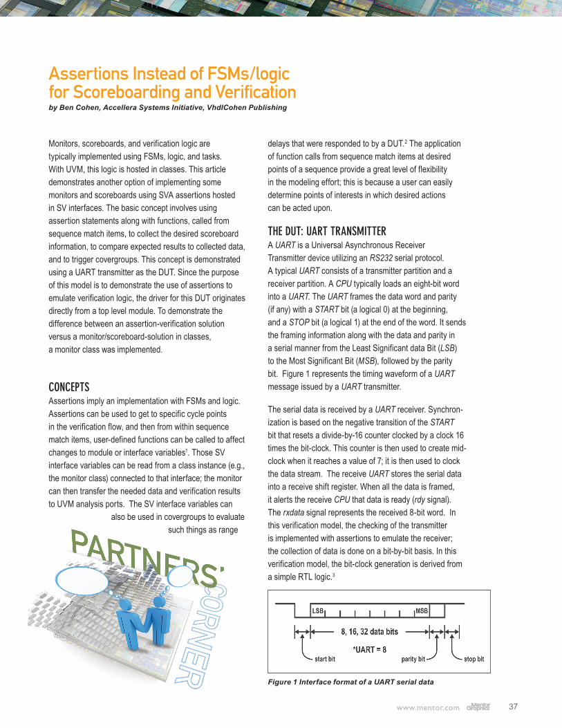
THE DUT: UART TRANSMITTER A UART is a Universal Asynchronous Receiver Transmitter device utilizing an RS232 serial protocol. A typical UART consists of a transmitter partition and a receiver partition. A CPU typically loads an eight-bit word into a UART. The UART frames the data word and parity (if any) with a START bit (a logical 0) at the beginning, and a STOP bit (a logical 1) at the end of the word. It sends the framing information along with the data and parity in a serial manner from the Least Significant data Bit (LSB) to the Most Significant Bit (MSB), followed by the parity bit. Figure 1 represents the timing waveform of a UART message issued by a UART transmitter.
The serial data is received by a UART receiver. Synchron-ization is based on the negative transition of the START bit that resets a divide-by-16 counter clocked by a clock 16 times the bit-clock. This counter is then used to create mid-clock when it reaches a value of 7; it is then used to clock the data stream. The receive UART stores the serial data into a receive shift register. When all the data is framed, it alerts the receive CPU that data is ready (rdy signal). The rxdata signal represents the received 8-bit word. In this verification model, the checking of the transmitter is implemented with assertions to emulate the receiver; the collection of data is done on a bit-by-bit basis. In this verification model, the bit-clock generation is derived from a simple RTL logic.3
Figure 1 Interface format of a UART serial data
Assertions Instead of FSMs/logic for Scoreboarding and Verification by Ben Cohen, Accellera Systems Initiative, VhdlCohen Publishing
38
PARITY: If parity is enabled, then this bit shall represent the even or odd parity of the data word. For even parity, the parity bit is such that the number of ONEs in the word message and the parity bit will be an even number. For odd parity, the parity bit is such that the number of ONEs in the word message and the parity bit will be an odd number. The parity bit shall be the exclusive OR of the desired parity mode (‘0’ for even, or ‘1’ for odd) and the data word. If parity is disabled, then this bit shall be omitted.
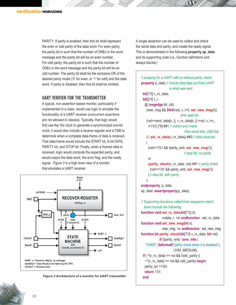
UART VERIFIER FOR THE TRANSMITTER A typical, non assertion-based monitor, particularly if implemented in a class, would use logic to emulate the functionality of a UART receiver (concurrent assertions are not allowed in classes). Typically, that logic would first use the 16x clock to generate a synchronized one-bit clock; it would also include a receive register and a FSM to determine when a complete data-frame of data is received. That data-frame would include the START bit, 8-bit DATA, PARITY bit, and STOP bit. Finally, when a framed data is received, logic would compute the expected parity, and would output the data word, the error flag, and the ready signal. Figure 2 is a high level view of a monitor that emulates a UART receiver.
Figure 2 Architecture of a monitor for UART transmitter
A single assertion can be used to collect and check the serial data and parity, and create the ready signal. This is demonstrated in the following property ap_data, and its supporting code (i.e., function definitions and always blocks).4
// property for a UART with or without parity checkproperty p_data; // checks that data out from UART is what was sent bit[7:0] v_rx_data; bit[2:0] v_i; @ (negedge bit_clk) (new_msg && $fell(rxd), v_i=0, set_new_msg(0)) |=>// start bit (rxd==sent_data[v_i], v_rx_data[v_i] =rxd, v_i=v_ i+1’b1) [*8] ##1 // collect and check //the serial bits, LSB first (1, set_rx_data(v_rx_data)) ##0 // data received ( (rxd==1’b1 && !parity_enb, set_new_msg(1)) // stop bit, no parity or (parity_check(v_rx_data, rxd) ##1 // parity check (rxd==1’b1 && parity_enb, set_new_msg(1)) ) // stop bit, with parity ); endproperty :p_dataap_data: assertproperty(p_data);
// Supporting functions called from sequence match items include the following: function void set_rx_data(bit[7:0] d); rxdata_r =d; endfunction : set_rx_datafunction void set_new_msg(bit x); new_msg =x; endfunction : set_new_msgfunction bit parity_check(bit[7:0] v_rx_data, bit rxd); if (!parity_enb) `uvm_info ( “CHKR”, $sformatf(“parity check when it is disabled”), UVM_MEDIUM); if ( ^{v_rx_data} == rxd && !odd_parity || ~^{v_rx_data} == rxd && odd_parity) begin parity_err =1’b0; return 1’b1; end
39
else begin parity_err =1’b1; return 1’b0; endendfunction : parity_check
always @ (posedge clk16x) begin if($rose(new_msg)) rdy<= 1’b1; else rdy<= 1’b0; end
Using the mid-bit extracted clock (i.e., (negedge bit_clk)), the property p_data performs the following data gathering and check tasks:5
1. It is triggered by (new_msg && $fell(rxd), meaning that we’re awaiting a new_message (i.e., no word being processed) and a START bit is detected. At that point, the data bit index v_i is reset to zero, and the new message flag (new_msg) is reset, thus avoid any re-triggering of the property until it is completed. This is represented in SVA by the antecedent
(new_msg && $fell(rxd), v_i=0, set_new_msg(0))
2. For the next 8 cycles, serial data is collected and verified on a bit-by-bit basis against expected data. That expected data is the sent_data from the driver, which is a synchronous copy of item_h.data, where item_h is the handle in the DUT interface, and data is the data word written to the DUT that gets serialized and sent by the DUT. That handle is updated from the driver. A copy is needed because handles are not allowed in assertion statements. In the assertion, the serial data to be verified is stored into a local property variable. This is represented in SVA by:
(rxd== sent_data[v_i], //DUT serial data bit[v_i] == expected data [v_i] v_rx_data[v_i] =rxd, v_i=v_i+1’b1) [*8] // collect data word
3. At the end of the data reception, and at the next cycle, the collected data is saved into the received data variable
using the set_rx_data function; the data is saved for potential other applications, if needed. This is represented in SVA by:
##1 (1, set_rx_data(v_rx_data)) ##0 // data received.
In that same next cycle, if parity is disabled, then that received bit is the STOP bit. This is represented in SVA by:
(rxd==1’b1 && !parity_enb, set_new_msg(1))
In that cycle, the new message flag is set to 1 to await another message. However, if parity is enabled, then that received bit is the PARITY bit followed by the STOP bit. This is represented in SVA by:
( (rxd==1’b1 && !parity_enb, set_new_msg(1)) // stop bit, no parity or ( parity_check(v_rx_data, rxd) ##1 // parity check (rxd==1’b1 &&parity_enb, set_new_msg(1)) ) // stop bit, with parity
The above data collection and verification can be performed in classes, using an RTL-like style. This represents an almost FSM-equivalent of the assertion ap_data; specifically, the task xmt_tsk collects the receive serial data and then check for its correctness. That task addresses the odd parity case for simplicity.
taskxmt_tsk; forever begin @ (posedge vif.clk16x) begin :Rx_Lbl this.rxd_r<= vif.serial_out; //-- reset if (vif.rst_n == 1’b0) begin count16_r <= 4’b0000; // reset divide by 16 counter rxmt_r<= 1’b1; // new message starting rxdata_r<= 11’b111_1111_1111; end
40
// new bit start else if (rxmt_r&&rxd_r == 1’b0) begin count16_r <= 4’b0000; // reset divide by 16 counter rxmt_r<= 1’b0; // new message starting rxdata_r<= 11’b111_1111_1111; end // If in a receive transaction mode // if @ mid bit clock then clock data into register else if (count16_r == 4’b111 &&rxmt_r==1’b0) begin// mid clock rxdata_r<= {rxd_r, rxdata_r[10:1]}; count16_r <= count16_r + 1’b1; end // if @ 16X clock rollover else if(count16_r == 4’b1111) count16_r <= 0;
// Check if a data word is received if (rxmt_r==1’b0 && rxdata_r[10]== 1’b1 && rxdata_r[0]== 1’b0) begin rdy<= 1’b1; //rx_data<= rxdata_r[8:1]; rxmt_r<= 1’b1; parity_check(rxdata_r[8:1], rxdata_r[9]); check_data(rxdata_r[8:1]); end else rdy<= 1’b0; end :Rx_Lbl endendtask :xmt_tsk
The advantage of having the assertion property record the received data in the interface is that the data is then available to a monitor in UVM, for example, to assemble it into a transaction object and broadcast it to the rest of the UVM environment via its analysis_port. This allows the data to be checked immediately in the assertion before
the monitor is even notified that the data is present. This simplifies the monitor code and ensures that only valid data transactions are communicated.
CONCLUSIONS Assertion statements are very powerful SystemVerilog language features; this is particularly true when they are combined with local assertion statement variables, and with sequence match items where these local variables and design variables (in interfaces or modules) can be modified through function calls. In addition, assertions provide a different viewpoint than an RTL-like approach to implement the monitoring/scoreboarding functions. They are easier to create, understand, and debug. Some users may find that a state machine implementation is easier to follow because of familiarity; however, that solution may fall into the same trap of providing another RTL-like modeling with the same issues of verification as any other RTL model. Assertions provide a different level of thinking about addressing the verification tasks with an approach that is more expressive and easier to follow than logic; this is because a user can easily determine points of interests in which desired actions, fired from function calls in sequence match items, can be acted upon.
END NOTES
1 See 1800-2012:: 16.11 Calling subroutines on match of a sequence
2 See the following white paper for an example of using assertions for scoreboarding and covergroup Using SVA for scoreboarding and TB designs, Ben Cohen http://systemverilog.us/papers/sva4scoreboarding.pdf
3 Assertions with function calls from sequence match items can be used to generate that bit-clock as extracted using the 16x-clock and the start frame synchronization information; this novel application of assertion statements is demonstrated in http://SystemVerilog.us/uart_bit_clk_gen.pdf.
4 All test code and test results can be downloaded from http://systemverilog.us/uart4hz.tar
5 The generation of bit-clock is the uart_if.sv file.
Editor: Tom FitzpatrickProgram Manager: Rebecca Granquist
Wilsonville Worldwide Headquarters8005 SW Boeckman Rd.Wilsonville, OR 97070-7777Phone: 503-685-7000
To subscribe visit: www.mentor.com/horizons
To view our blog visit:VERIFICATIONHORIZONSBLOG.COM