18
Asservicement
| Date post: | 27-Dec-2015 |
| Category: |
Documents |
| Upload: | logan-booker |
| View: | 219 times |
| Download: | 0 times |
Asservicement

Asservicement
The asservicement is a form of intelligent motor control. Its purpose is to ensure the rotation of the Lavet motor while using as little power as possible.
The asservicement utilizes two functions to accomplish these goals:
– Chopped Motor Drive– Step Detection

Chopped Motor Drive
For most efficient operation, the motor needs to be driven with as little current as possible.
The theory behind a chopped motor drive is that a motor’s torque can be changed by quickly turning its supplied power on and off.
Essentially, the higher % of the time the power is turned on, the higher the current supplied and torque output of the motor.
This can be visualized as the area under a line of a graphed output.

Chopped Motor Drive
75% Output0v
1.5v
25% Output0v
1.5v
100% Output0v
1.5v
Modulation of Pulse Width
Modulation of Duty Cycle
You can modulate either the duty cycle of the pulse over a set time or modify the pulse width to achieve essentially
the same effective driving force.

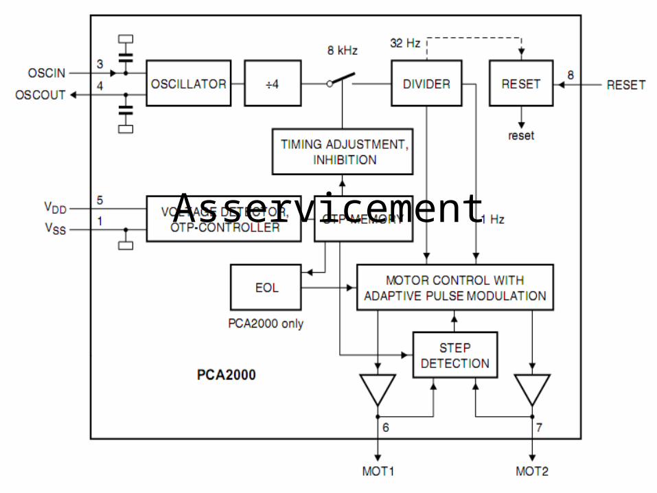
Step Detection
Step detection is the portion of the asservicement which ensures the Lavet motor (bi-polar stepping motor) has advanced one step (180˚ of rotor rotation).
If a missing step is detected, the step detection indicates to the motor control that the step has not occurred.
The step detector works by reading the voltage generated in the coil by the motion of the rotor.

Step 1 – Normal Operation
The Motor Control receives a signal from the final divider.
Motor Control
Step Detection
Mot 1 Mot 2
+
-Animate

Step 2 – Normal Operation
The Motor Control sends an impulse to the coil.
Motor Control
Step Detection
Mot 1 Mot 2
+
-Animate
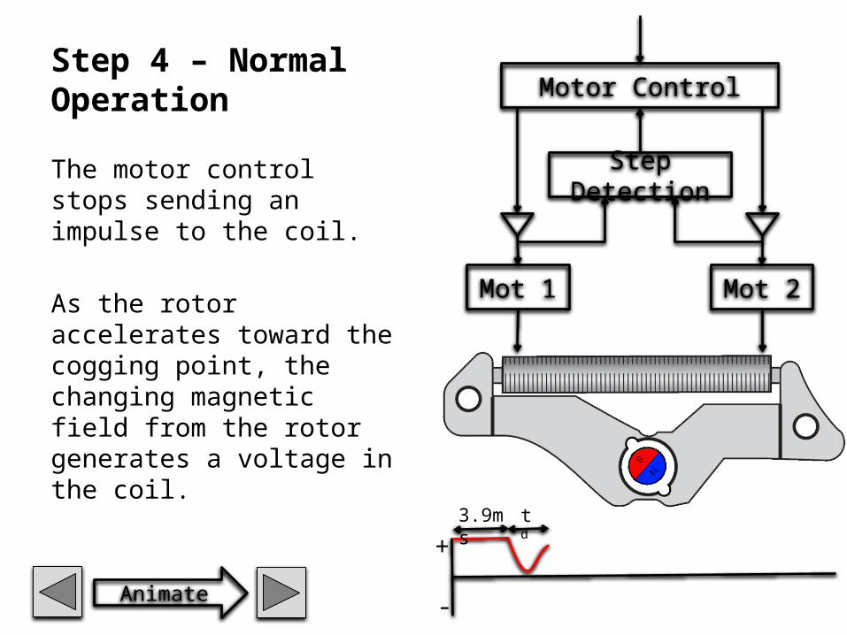
Step 4 – Normal Operation
The motor control stops sending an impulse to the coil.
As the rotor accelerates toward the cogging point, the changing magnetic field from the rotor generates a voltage in the coil.
Motor Control
Step Detection
Mot 1 Mot 2
+
-Animate
3.9ms td

Step 5 – Normal Operation
The rotor comes to rest at the cogging point with a back and forth motion. This creates an oscillating voltage in the coil.
Motor Control
Step Detection
Mot 1 Mot 2
+
-Animate
3.9ms td Step Detection

Step 6 – Normal Operation
The step detection listens to the coil for this oscillating voltage.
If it is present, a step has occurred and nothing else happens until the motor control receives another signal from the final divider.
If the oscillating voltage is not present, the step detector sends a signal to the motor control.
Motor Control
Step Detection
Mot 1 Mot 2
+
-Animate
3.9ms td Step Detection

Step 1 – Non Operation
The Motor Control receives a signal from the final divider.
Motor Control
Step Detection
Mot 1 Mot 2
+
-Animate
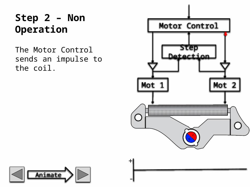
Step 2 – Non Operation
The Motor Control sends an impulse to the coil.
Motor Control
Step Detection
Mot 1 Mot 2
+
-Animate
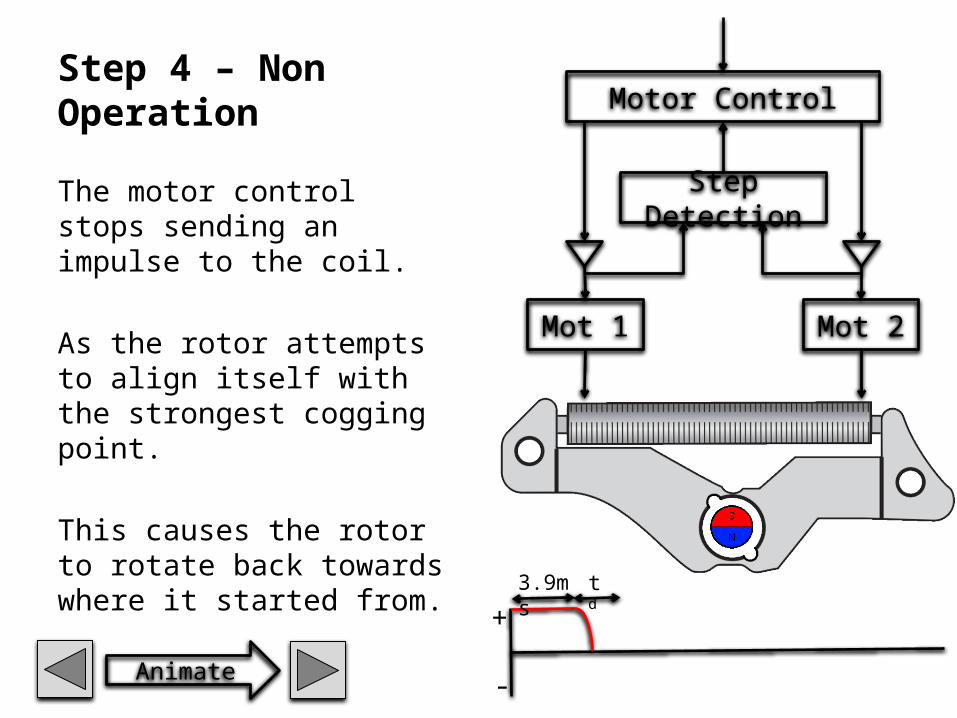
Step 4 – Non Operation
The motor control stops sending an impulse to the coil.
As the rotor attempts to align itself with the strongest cogging point.
This causes the rotor to rotate back towards where it started from.
Motor Control
Step Detection
Mot 1 Mot 2
+
-Animate
3.9ms td

Step 5 – Non Operation
The rotor stopped moving when it moved back to its starting position.
At this point in time, instead of oscillating to a halt, the rotor is motionless.
The non-motion of the rotor does NOT generate any voltage in the coil.
Motor Control
Step Detection
Mot 1 Mot 2
+
-
3.9ms td Step Detection

Step 6 – Non Operation
The step detection listens to the coil for the oscillating voltage.
Since it is not present, the step detector sends a signal to the motor control.
The motor control sends a larger impulse to the coil in an attempt to operate the motor.
This continues until:– The rotor rotates 180˚– The maximum # of attempts
has been reached.
Motor Control
Step Detection
Mot 1 Mot 2
+
-Animate
3.9ms td Step Detection

Normal Operation
Complete process of the asservicement
Non Operation
Complete process of the asservicement
Side by side
Complete process of the asservicement


